download the full paper here
9
1. INTRODUCTION Conventionally, numerical approaches used in rock mechanics are based on either continuum or discrete (discontinuum) formulations. These approaches fail to capture the emergence of new discontinuities generated by brittle fracturing processes. Over the last decade, multiple numerical approaches have been developed and applied to overcome this limitation (Lisjak & Grasselli, 2014). Among these methods, bonded discrete element models explicitly capture fracturing of brittle geomaterials by introducing cohesive contact models between the blocks or particles used to represent the solid structure. Alternatively, advanced continuum approaches, including the generalized finite element method (GFEM) and the extended finite element method (XFEM), have been proposed. In recent years, the combined (or hybrid) finite-discrete element method (FDEM) pioneered by Munjiza (2004) and implemented in the Y-Geo code (Mahabadi et al., 2012) has emerged as a promising technique to explicitly simulate fracture and fragmentation processes in brittle geomaterials. FDEM is an explicit numerical method which combines continuum mechanics principles with discrete element algorithms to simulate multiple interacting deformable and fracturable solids. While the elastic deformation of discrete bodies is described by the continuum finite element method (FEM), the contact detection and interaction of discrete bodies is captured using aspects of the discrete element method (DEM). The progressive mechanical breakdown and failure of rock material is represented using a cohesive fracture model. An FDEM simulation can comprise of millions of pairs of interacting elements. The required contact detection and interaction calculations, together with the complexity added by introducing cohesive crack elements and the associated fracture model calculations, deem FDEM simulations computationally expensive. As a result, despite the great potential of FDEM in realistically reproducing fracture and fragmentation processes in brittle materials, its application has been limited to mainly research projects. The current work at Geomechanica aims to overcome the computational limitations of FDEM by developing a new, fully-parallel commercial code known as Irazu. With Irazu, the parallel processing power of General- Purpose Graphics Processing Units (GPGPUs) has been leveraged to gain a significant performance boost compared to a sequential code working on the CPU (i.e., Y-Geo). To take full advantage of the parallel computing ARMA 16-516 Development of a new fully-parallel finite-discrete element code: Irazu Mahabadi, O.K., Lisjak, A., He, L., Tatone, B.S.A., Kaifosh, P. Geomechanica Inc., Toronto, Ontario, Canada Grasselli, G. University of Toronto, Toronto, Ontario, Canada Copyright 2016 ARMA, American Rock Mechanics Association This paper was prepared for presentation at the 50 th US Rock Mechanics / Geomechanics Symposium held in Houston, Texas, USA, 26-29 June 2016. This paper was selected for presentation at the symposium by an ARMA Technical Program Committee based on a technical and critical review of the paper by a minimum of two technical reviewers. The material, as presented, does not necessarily reflect any position of ARMA, its officers, or members. Electronic reproduction, distribution, or storage of any part of this paper for commercial purposes without the written consent of ARMA is prohibited. Permission to reproduce in print is restricted to an abstract of not more than 200 words; illustrations may not be copied. The abstract must contain conspicuous acknowledgement of where and by whom the paper was presented. ABSTRACT: This paper presents the development and verification of a new, fully-parallel, hydro-mechanically-coupled simulation software (Irazu) based on the finite-discrete element method (FDEM). Irazu is a general-purpose numerical simulation software which combines continuum mechanics principles with discrete element algorithms to simulate the mechanical response of brittle geomaterials. To overcome the computational limitations of FDEM codes, Irazu utilizes the parallel processing power of general-purpose graphics processing units (GPGPUs). As a result, Irazu shows impressive speedups compared with a sequential central processing unit (CPU) FDEM code. The code capabilities are illustrated herein by simulating the complex failure mechanics of bedded rock samples. A case study to assess the stability of the overhang of a mine loading pocket demonstrates Irazu’s application to field-scale problems. Overall, superior physics and computational performance make Irazu a state-of-the-art, commercial simulation tool for tackling complex geomechanical applications in mining, civil, and petroleum engineering.
Transcript of download the full paper here

1. INTRODUCTION
Conventionally, numerical approaches used in rock mechanics are based on either continuum or discrete (discontinuum) formulations. These approaches fail to capture the emergence of new discontinuities generated by brittle fracturing processes. Over the last decade, multiple numerical approaches have been developed and applied to overcome this limitation (Lisjak & Grasselli, 2014). Among these methods, bonded discrete element models explicitly capture fracturing of brittle geomaterials by introducing cohesive contact models between the blocks or particles used to represent the solid structure. Alternatively, advanced continuum approaches, including the generalized finite element method (GFEM) and the extended finite element method (XFEM), have been proposed. In recent years, the combined (or hybrid) finite-discrete element method (FDEM) pioneered by Munjiza (2004) and implemented in the Y-Geo code (Mahabadi et al., 2012) has emerged as a promising technique to explicitly simulate fracture and fragmentation processes in brittle geomaterials. FDEM is an explicit numerical method which combines continuum mechanics principles with discrete element algorithms to simulate multiple interacting deformable and fracturable solids. While the elastic deformation of
discrete bodies is described by the continuum finite element method (FEM), the contact detection and interaction of discrete bodies is captured using aspects of the discrete element method (DEM). The progressive mechanical breakdown and failure of rock material is represented using a cohesive fracture model.
An FDEM simulation can comprise of millions of pairs of interacting elements. The required contact detection and interaction calculations, together with the complexity added by introducing cohesive crack elements and the associated fracture model calculations, deem FDEM simulations computationally expensive. As a result, despite the great potential of FDEM in realistically reproducing fracture and fragmentation processes in brittle materials, its application has been limited to mainly research projects.
The current work at Geomechanica aims to overcome the computational limitations of FDEM by developing a new, fully-parallel commercial code known as Irazu. With Irazu, the parallel processing power of General-Purpose Graphics Processing Units (GPGPUs) has been leveraged to gain a significant performance boost compared to a sequential code working on the CPU (i.e., Y-Geo). To take full advantage of the parallel computing
ARMA 16-516 Development of a new fully-parallel finite-discrete element code: Irazu
Mahabadi, O.K., Lisjak, A., He, L., Tatone, B.S.A., Kaifosh, P. Geomechanica Inc., Toronto, Ontario, Canada
Grasselli, G. University of Toronto, Toronto, Ontario, Canada
Copyright 2016 ARMA, American Rock Mechanics Association
This paper was prepared for presentation at the 50th US Rock Mechanics / Geomechanics Symposium held in Houston, Texas, USA, 26-29 June 2016. This paper was selected for presentation at the symposium by an ARMA Technical Program Committee based on a technical and critical review of the paper by a minimum of two technical reviewers. The material, as presented, does not necessarily reflect any position of ARMA, its officers, or members. Electronic reproduction, distribution, or storage of any part of this paper for commercial purposes without the written consent of ARMA is prohibited. Permission to reproduce in print is restricted to an abstract of not more than 200 words; illustrations may not be copied. The abstract must contain conspicuous acknowledgement of where and by whom the paper was presented.
ABSTRACT: This paper presents the development and verification of a new, fully-parallel, hydro-mechanically-coupled simulation software (Irazu) based on the finite-discrete element method (FDEM). Irazu is a general-purpose numerical simulation software which combines continuum mechanics principles with discrete element algorithms to simulate the mechanical response of brittle geomaterials. To overcome the computational limitations of FDEM codes, Irazu utilizes the parallel processing power of general-purpose graphics processing units (GPGPUs). As a result, Irazu shows impressive speedups compared with a sequential central processing unit (CPU) FDEM code. The code capabilities are illustrated herein by simulating the complex failure mechanics of bedded rock samples. A case study to assess the stability of the overhang of a mine loading pocket demonstrates Irazu’s application to field-scale problems. Overall, superior physics and computational performance make Irazu a state-of-the-art, commercial simulation tool for tackling complex geomechanical applications in mining, civil, and petroleum engineering.

nature of the GPGPU, efficient parallel algorithms have been developed for performing contact detection, hash table implementation, and other functions. In addition, Irazu can use state-of-the-art cloud computing developments to execute the simulations remotely in the cloud, thus minimizing the hardware and maintenance fees typically associated with traditional simulation software.
Irazu has been tested rigorously against known analytical solutions, laboratory, and field observations, as well as previous FDEM results obtained using Y-Geo (Geomechanica Inc., 2016). In all cases, Irazu simulations have been able to reproduce the expected behavior, both qualitatively (e.g., fracturing processes) and quantitatively (e.g., peak strength, breakdown pressures).
In the current paper, two practical cases have been chosen to demonstrate the accuracy of results: a series of laboratory tests on a bedded rock; and a larger-scale model of mine loading pocket stability. Realistic deformation and fracturing behavior are reproduced in these simulations with substantially decreased computational times compared to typical FDEM simulations (i.e., minutes instead of hours and hours instead of days).
2. IRAZU FDEM PRINCIPLES
A brief overview of the major FDEM principles implemented in Irazu are presented here. For further details and mathematical formulations, the reader is referred to the Irazu theory manual (Geomechanica Inc., 2016).
2.1. Governing equation In Irazu, each intact body is discretized with a mesh comprised of 3-noded triangular elements. The generalized governing equation of motion can be expressed as: + + − − − = 0 (1)
where M is the lumped mass matrix, C is the viscous damping matrix (applied to dissipate dynamic oscillations in the model), x is the vector of nodal displacements, fint is the vector of internal resisting forces, including elastic reaction forces and crack element bonding forces, fext is vector of external forces, fc is vector of contact forces, and ffl is vector of fluid-pressure forces. The equation of motion is integrated at each simulation time step to update the nodal coordinates.
2.2. Material deformation The elastic deformation of intact material is modeled according to the continuum theory of linear elasticity using constant-strain triangular elements (Munjiza,
2004). Element deformation (strain) at each time step is described by the differences between its initial configuration (i.e., undeformed) and current configuration (i.e., deformed). From the strain tensor, the element stress tensor is calculated using constitutive laws for:
• isotropic linear elasticity based on plane stress or plane strain assumptions; or
• transversely isotropic linear elasticity.
2.3. Contact detection and interaction An FDEM simulation in Irazu can involve a large number of interacting discrete elements. To correctly capture this behavior, contacting couples (i.e., pairs of contacting discrete elements) must first be detected. Detection is accomplished using a spatial hashing contact detection algorithm optimized for the GPGPU.
Subsequently, the interaction forces resulting from the detected contacts can be defined. Contact interaction forces are calculated between all pairs of elements that overlap in space. In the normal direction, repulsive forces are applied to enforce a body impenetrability condition, while in the tangential direction, frictional forces are applied.
The repulsive forces between contacting elements (i.e., pairs) are calculated using a distributed contact force penalty function method (Munjiza & Andrews, 2000). According to this method, it is assumed that pairs of contacting elements penetrate into each other and thereby generate contact forces that depend on the size and shape of the resulting overlapping area.
The frictional forces between contacting couples are calculated using a Coulomb-type friction law (Mahabadi et al., 2012). These frictional forces are applied to intact material and pre-existing and newly-created fractures. Given the explicit integration scheme, the frictional resistance must be mobilized over some finite amount of relative displacement between the interacting edges.
2.4. Fracture model The initiation and propagation of fractures are explicitly simulated in Irazu using concepts of non-linear fracture mechanics (NLFM) (Barenblatt, 1962; Dugdale, 1960). According to this theory, as the tensile strength of a material is exceeded at the tip of an opening (Mode I) crack, a zone characterized by non-linear behavior, called the fracture process zone (FPZ), begins to form (Fig. 1a). In brittle geomaterials, the FPZ is characterized by interlocking and micro-cracking and, albeit damaged, is capable of transferring load across the fracture walls (Labuz et al., 1985) (Fig. 1b). Within Irazu, an analogous FPZ behavior is also assumed to exist ahead of crack tips subjected to Mode II loading.

The existence and load carrying capacity of the FPZ are approximated by way of four-noded cohesive crack elements (Fig. 1c). These elements are inserted coincident with the edges of all triangular finite elements (Fig. 1d). Thus, arbitrary fracture trajectories are free to develop within the constraints imposed by the mesh topology. Depending on the local stress and relative crack wall displacements, the crack elements may yield and break under Mode I (i.e., opening mode), Mode II (i.e., sliding mode) or mixed-Mode I − II conditions.
Fig. 1 (a) Schematic of Fracture Process Zone (FPZ) in brittle geomaterials (after Labuz et al., 1985); (b) theoretical FPZ model (after Hillerborg et al., 1976); (c) numerical representation of theoretical FPZ model in Irazu FDEM (after Lisjak et al., 2013); and (d) exaggerated view of 4-noded crack elements located along edges of all adjoining triangular finite elements (after Lisjak et al. 2013).
According to a cohesive model similar to that originally proposed by Hillerborg et al. (1976), Mode I fracture initiation and propagation occurs when the opening of a crack element, o, reaches a critical value, op, corresponding to the intrinsic tensile strength of the element, ft (Fig. 2a). As a crack element is opened beyond op, the normal stress, σ, is assumed to gradually decrease until o exceeds the residual opening value, or, at which point a traction-free surface is formed.
According to a slip-weakening model conceptually similar to that proposed by Ida (1972), Mode II fracture initiation and propagation occurs when the tangential slip of a crack element, s, reaches a critical value sp, corresponding to the intrinsic shear strength of the element, fs (Fig. 2b), defined as = + tan (2)
where c is the internal cohesion, is the intact material friction angle, and is the normal stress acting across the crack element. As a crack element sustains further slip beyond sp, the tangential stress, τ, is assumed to gradually decrease until s exceeds the residual slippage, sr. At this point, a physical discontinuity is formed and τ becomes equal to a purely frictional resistance, given by tan , where is the fracture friction angle.
Instead of pure Mode I or pure Mode II displacements, crack elements often experience a combination of the two (mixed Mode I − II displacement). With mixed Mode I − II displacement, the o and s of a crack element may be less than or and sr, respectively, but the resultant crack displacement can be quite large. For such cases, a criterion for mixed-Mode I − II crack initiation and propagation is needed. In Irazu FDEM, mixed-Mode I-II fracturing of a crack element occurs if the following coupling criterion between o and s is satisfied (Fig. 2c): − 1. (3)
The values of residual opening, or and slip, sr , depend on the values of ft and fs, as well as the Mode I and Mode II fracture energy release rates, GfI and GfII. The values of GfI and GfII include the contributions of the surface energy 2γ of the newly created crack surfaces along with the energy consumed in the damage process and by friction and are equal to the area under the curves in Fig. 2a, b given
=
= − (4)
Fig. 2 Fracture model implemented in FDEM: (a) cohesive model for Mode I, (b) slip-weakening model for Mode II, and (c) criterion for mixed-Mode fracture initiation.
A modified version of the crack element formulation described above can be used to model transversely isotropic materials. In particular, according to the model developed by Lisjak et al. (2014), the anisotropy in strength is introduced at the crack element level by specifying the cohesive strength of each crack element

as a function of its orientation, γ, relative to planes of weakness such as bedding planes, fissility, or schistosity (Fig. 3a). The cohesive strength parameters and the fracture energies are assumed to vary linearly between a minimum value for γ = 0° (i.e., ft,min, cmin, GfI,min, GfII,min) to a maximum value for γ = 90° (i.e., ft,max, cmax, GfI,max, GfII,max). Furthermore, the mesh topology can be modified such that it combines a random triangulation for the intra-layer material (i.e., matrix) with crack elements aligned along preferentially oriented planes of weakness (Fig. 3b).
Fig. 3 Modeling of strength anisotropy: (a) linear variation of cohesive strength parameters with the angle, γ, between crack element and layering orientation; and (b) example of mesh combining a Delaunay triangulation for the intra-layer material with edges preferentially aligned to represent planes of weakness (after Lisjak et al., 2014).
2.5. Hydraulic solver Fluid flow is assumed to occur through a flow network generated from the same triangular mesh used for the mechanical calculations (similar to Fig. 1d). Flow channels are created at the interfaces between adjoining triangular finite elements. These flow channels are connected together via virtual cavities that correspond to the nodes of the original finite element mesh. Flow channels can also be connected to actual fluid-filled void spaces in the model (e.g., boreholes). Each cavity represents a fluid reservoir with a uniform pressure. Since the fluid mass is transferred between cavities via flow channels, fluid flow and fluid pressure dissipation can occur only through the network of flow channels.
Flow through the channel network is modeled employing principles of lubrication theory (Batchelor, 1967) using an explicit hydraulic solver. During each hydraulic time step, the following main operations are sequentially performed: (i) determination of volume and saturation of the cavities, as well as hydraulic aperture of the channels; (ii) application of the conservation of momentum for each channel; (iii) application of the continuity equation at each cavity; and (iv) computation of the fluid pressure field. The mathematical formulation at the basis of the above steps is described in Irazu’s theory manual (Geomechanica Inc., 2016) and Lisjak et al (2016).
2.6. Advanced features Irazu is equipped with more advanced features, including:
• Explicit definition of strength and hydraulic parameters at material interfaces.
• Staged excavations. • Mechanical and hydraulic discrete fracture
network (DFN) embedding. Mechanically, DFNs can be cohesive or non-cohesive (frictional) and, hydraulically, they can be impermeable or permeable.
• In-situ stress initialization using a uniform or linearly-varying stress field.
• Seismic monitoring function to assess the seismic energy released during fracture propagation by computing the kinetic energy of nodes in proximity of crack tips.
• Time-variation of almost all input parameters. • Simplified adaptive fluid pressure boundary
condition: This model is hydro-mechanically coupled in the sense that variations in cavity volume, due to either rock elastic deformation or fracturing, affect the pressure of the compressible fluid, which, in turn, affects rock deformation and failure. The solid matrix is assumed impermeable. Viscous dissipations, due to the flow of fluid in the fracture network, are neglected.
An Irazu simulation can be purely elastic (calling FEM only) or “fracturable” (calling entire FDEM). It can also be purely hydraulic or mechanical, or fully coupled hydro-mechanical.
2.7. Computational implementation In recent years, heterogeneous computing based on SIMD (Single Instruction Multiple Date) architecture devices like GPGPUs has played a key role in boosting the computation power for data intensive applications (Mittal & Vetter, 2015). An application that uses state-of-the-art parallel computing techniques can potentially gain a speedup of ten to several hundred times over the equivalent sequential code. In this context, CUDA from Nvidia and OpenCL from KHRONOS Group are two major parallel programming models for heterogeneous computing on GPGPUs. The basic idea of these models is grouping critical computational tasks into functions called kernels that can run on the device by means of grouped threads. When scheduled onto computing units, the thread groups will execute in parallel to realize a performance improvement.
As previously explained, Irazu simulations can comprise of hundreds of thousands or millions of finite, discrete, and crack elements. As such, massive double-precision floating point computations are performed to compute the nodal forces and solve the equations of motion. As

most of the computations do not depend on each other, there is no need for extensive communication among kernels/threads except for writing the results and updating nodal coordinates. Thus, this computational model is well suited to heterogeneous computing on GPGPUs.
The whole framework of the Irazu simulation is comprised of a loop over a pre-defined number of time steps, and in each time step, elastic deformation, fracture, contact detection, and interaction kernels are called in sequence. In each kernel (e.g., finite element deformation), one parallel running thread works for one element, and computes the forces on the nodes of the element based on the deformation model. The other main kernels work in a similar way. Furthermore, to get an even better performance, Irazu optimizes the code according to GPGPU features such as organizing the data in an aliased way, avoiding branch divergence, and bank conflict.
3. VERIFICATION AND CASE STUDIES
Irazu has been thoroughly validated against laboratory and field data, as well empirical solutions and previous modelling results. A full list of verification examples can be found in Irazu’s verification manual (Geomechanica, 2015). Herein, only one case study is presented.
3.1. Mechanical solver verification In this case study, the mechanical behavior of Opalinus Clay (OPA) samples during standard rock mechanics testing was considered. OPA is a clay shale formation currently being assessed as a host rock for the deep geological repository for the disposal of nuclear waste in Switzerland. These results are part of a broader research project in which finite-discrete element simulations are employed to investigate the fracturing behavior of Opalinus Clay with a focus on the initiation and evolution of the so-called excavation damaged zone (EDZ) around underground structures (Lisjak et al., 2015; Mahabadi et al., 2014).
To capture the distinctively anisotropic behavior of OPA, a transversely isotropic elastic constitutive model was used for the finite elements in combination with the anisotropic crack element formulation (Fig. 3). The input parameters were calibrated by comparing the emergent properties of the simulations to the relevant response of OPA in laboratory tests. Specifically, the strength parameters were adjusted to match the indirect tensile strength, ft, and the unconfined compressive strength, UCS, of OPA. Given the strong dependence of the above macroscopic properties upon loading direction, samples parallel (P sample), perpendicular (S sample), and inclined at 45° with respect to the bedding (Z sample) were considered. Given the continuum formulation used to capture the elastic behavior, the
input values for the elastic constants were set equal to respective experimental values. As reported in Table 1, a good agreement was obtained between the numerical emergent properties and the associated experimental values. Subsequently, biaxially-confined compression test simulations were carried out by applying a lateral pressure to the previously calibrated UCS models.
Table 1. Comparison between the mechanical properties of the Opalinus Clay and the calibrated emergent properties simulated with Irazu. Experimental values were provided by the Swiss nuclear waste management organization (Nagra).
Property Experimental range
Irazu
Young's modulus parallel to bedding, Ep (GPa)
11.4 11.1
Young's modulus perpendicular to bedding, Es (GPa)
5.5 5.6
Poisson’s ratio parallel to bedding, νp 0.27 0.28
Poisson’s ratio perpendicular to bedding, νs
0.27 0.28
Uniaxial compressive strength parallel to bedding, UCSp (MPa)
22.3 – 33.7 24.7
Uniaxial compressive strength perpendicular to bedding, UCSs (MPa)
23.7 – 36.9 36.4
Uniaxial compressive strength at 45° to bedding, UCSz (MPa)
3.5 – 8.7 5.5
Indirect tensile strength parallel to bedding, ft,p (MPa)
2.5 2.7
Indirect tensile strength perpendicular to bedding, ft,s (MPa)
1.2 1.3
The simulated fracture patterns of the UCS simulations at three different loading orientation is depicted in Fig. 4. The results highlight a distinct variation of bedding influence on the macroscopic failure response of the sample as a function of the anisotropy direction. For vertical bedding planes (P sample), failure of the sample is induced by the extension of the bedding planes. Major cracks develop sub-parallel to the loading direction consisting of a combination of tensile splitting along layers and steeply inclined shear fractures. In the Z sample, failure occurs exclusively in the form of shear fracturing parallel to the preferably oriented bedding planes. Finally, for loading direction perpendicular to bedding (S sample), rupture of the sample occurs as shearing through the intact rock matrix (approximately inclined at an angle of 55°-60°).
An example of emergent stress-strain curves at increasing confining pressures is shown in Fig. 5 for the Z sample. The total volumetric strain was computed as = −
(5)
where Vc and Vi are the current (or deformed) and initial (or undeformed) sample volumes, respectively. The current (or deformed) volume of the sample varies
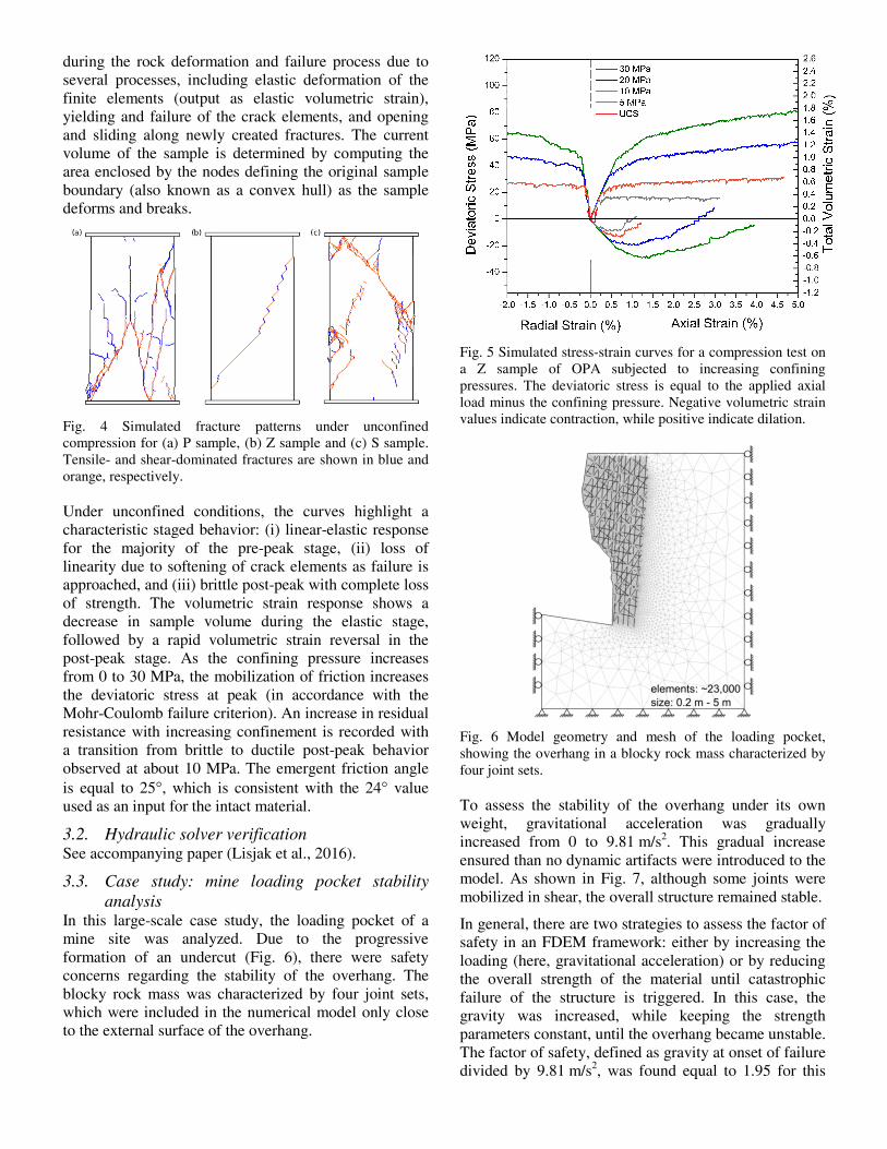
during the rock deformation and failure process due to several processes, including elastic deformation of the finite elements (output as elastic volumetric strain), yielding and failure of the crack elements, and opening and sliding along newly created fractures. The current volume of the sample is determined by computing the area enclosed by the nodes defining the original sample boundary (also known as a convex hull) as the sample deforms and breaks.
Fig. 4 Simulated fracture patterns under unconfined compression for (a) P sample, (b) Z sample and (c) S sample. Tensile- and shear-dominated fractures are shown in blue and orange, respectively.
Under unconfined conditions, the curves highlight a characteristic staged behavior: (i) linear-elastic response for the majority of the pre-peak stage, (ii) loss of linearity due to softening of crack elements as failure is approached, and (iii) brittle post-peak with complete loss of strength. The volumetric strain response shows a decrease in sample volume during the elastic stage, followed by a rapid volumetric strain reversal in the post-peak stage. As the confining pressure increases from 0 to 30 MPa, the mobilization of friction increases the deviatoric stress at peak (in accordance with the Mohr-Coulomb failure criterion). An increase in residual resistance with increasing confinement is recorded with a transition from brittle to ductile post-peak behavior observed at about 10 MPa. The emergent friction angle is equal to 25°, which is consistent with the 24° value used as an input for the intact material.
3.2. Hydraulic solver verification See accompanying paper (Lisjak et al., 2016).
3.3. Case study: mine loading pocket stability analysis
In this large-scale case study, the loading pocket of a mine site was analyzed. Due to the progressive formation of an undercut (Fig. 6), there were safety concerns regarding the stability of the overhang. The blocky rock mass was characterized by four joint sets, which were included in the numerical model only close to the external surface of the overhang.
Fig. 5 Simulated stress-strain curves for a compression test on a Z sample of OPA subjected to increasing confining pressures. The deviatoric stress is equal to the applied axial load minus the confining pressure. Negative volumetric strain values indicate contraction, while positive indicate dilation.
Fig. 6 Model geometry and mesh of the loading pocket, showing the overhang in a blocky rock mass characterized by four joint sets.
To assess the stability of the overhang under its own weight, gravitational acceleration was gradually increased from 0 to 9.81 m/s2. This gradual increase ensured than no dynamic artifacts were introduced to the model. As shown in Fig. 7, although some joints were mobilized in shear, the overall structure remained stable.
In general, there are two strategies to assess the factor of safety in an FDEM framework: either by increasing the loading (here, gravitational acceleration) or by reducing the overall strength of the material until catastrophic failure of the structure is triggered. In this case, the gravity was increased, while keeping the strength parameters constant, until the overhang became unstable. The factor of safety, defined as gravity at onset of failure divided by 9.81 m/s2, was found equal to 1.95 for this

case study. As depicted in Fig. 8, beyond this gravitational acceleration value, the surface was mobilized under shear along a preferably oriented joint. In this context, the simulated extent of damage can be used to assist in the design of support elements.
Fig. 7 Analysis of existing loading pocket showing distribution of displacement (left) and major principal stress (right) at equilibrium.
Fig. 8 Loading pocket failure due to an artificial increase in gravitational acceleration.
4. COMPUTATIONAL PERFORMANCE
To demonstrate the robustness of Irazu computations, five uniaxial compression models (UCS) with increasing number of finite elements were simulated using Irazu and the sequential code Y-Geo. The number of elements, nominal element size, and time step size are summarized in Table 2. Each of these models was executed for 10,000 time steps and the time spent between the first output (time step = 0) and the last one (time step = 10,000) was computed as the total simulation time. All simulations were performed on a standard desktop computer equipped with an Intel Core i7 CPU @ 3.4 GHz (over clocked to 4.0 GHz), 16 GB of RAM, and AMD/ati R9 200 series GPU with 3 GB of on-board memory.
Table 2. UCS models used for performance benchmarking.
Number of finite elements
Element size (mm)
Time step size (ms)
3,630 2.00 10-5 14,600 1.00 10-6 58,524 0.50 10-7
232,128 0.25 10-8 504,756 0.10 10-9
The speedup of Irazu over Y-Geo, as defined by the ratio of Y-Geo simulation time divided by Irazu simulation time, is presented in Fig. 9(top). Full contact detection refers to a full Irazu simulation where contact detection is performed at each time step. In contrast, fixed contact topology at t=0 refers to the case where no contact detection is performed and the contact topology is left unchanged during the simulation. The latter approach is only suitable for models with small displacements, where new contacting pairs are not formed during the simulation and only elements that initially shared an edge are assumed to be in contact. As this figure shows, Irazu exhibited a substantial speedup over Y-Geo, starting at around 5 times for the smallest model, but increasing to 30 times for the largest model. The speed gain for the model with fixed topology was even greater and peaked at over 42 times for the largest model. This trend shows that the GPGPU performance boost is maximized when more elements and, thus, more parallel working groups are employed.
As depicted in Fig. 9(bottom), Irazu showed a linear increase in the simulation time with an increase in the number of elements (R2=0.99). Although the simulation time in Y-Geo is also linearly proportional to the number of elements (see inset of Fig. 9 bottom), the slope of the line defining simulation time versus number of elements is significantly lower in Irazu (approximately 36 times), indicating a far superior computational efficiency. Overall, the results show an impressive speedup of simulations compared with the sequential Y-Geo code.
5. CONCLUDING REMARKS
A new, commercially-available simulation tool based on the finite-discrete element method was presented in this paper. The Irazu code is hydro-mechanically coupled and leverages the computational power of modern GPGPUs to gain a significant performance boost compared with sequential FDEM codes. The simulations of a bedded clay shale, which exhibits strong anisotropy, demonstrated the capabilities of the code in capturing complex mechanical and fracture behavior of rocks. A case study of a mine loading pocket showed the application of Irazu to handle practical engineering problems in rock mechanics. It is believed that superior physics and computational performance make Irazu a state-of-the-art, commercial simulation tool for tackling complex rock engineering applications in mining, civil,

oil & gas, and underground nuclear waste disposal industries.
Fig. 9 Top: Computational performance comparison between sequential Y-Geo and Irazu. Bottom: Irazu simulation time (sec) for running 10,000 time steps. Bottom, inset: Simulation time (sec) comparison between Y-Geo and Irazu for 10,000 time steps. Fixed contact topology at t=0 refers to the case where element contacts did not change over simulation time.
ACKNOWLEDGEMENTS
This work has been partly supported by the National Scientific and Engineering Research Council of Canada through two Industrial R&D Post-Doctoral Fellowships held by Dr. Andrea Lisjak and Dr. Bryan Tatone.
REFERENCES
1. Barenblatt, G. I. (1962). The mathematical theory of equilibrium cracks in brittle fracture. Advances in Applied Mechanics 789, 7, 55–129.
2. Batchelor, G. K. (1967). An Introduction to Fluid Dynamics. Book. doi:10.1063/1.3060769
3. Dugdale, D. S. (1960). Yielding of steel sheets containing slits. J.Mech.Phys.Solids, 8(290), 100–104.
4. Geomechanica Inc. (2016). Irazu software, version 1.2 Theory Manual.
5. Geomechanica Inc. (2016). Irazu software, version 1.2, Verification Manual.
6. Hillerborg, A., Modéer, M., and Petersson, P.-E. (1976). Analysis of crack formation and crack growth in concrete by means of fracture mechanics and finite elements. Cem.Concr.Res., 6(691), 773–781.
7. Ida, Y. (1972). Cohesive force across the tip of a longitudinal-shear crack and Griffith’s specific surface energy. Journal of Geophysical Research, 77(20), 3796–3805. doi:10.1029/JB077i020p03796
8. Labuz, J. F., Shah, S. P., and Dowding, C. H. (1985). Experimental analysis of crack propagation in granite. International Journal of Rock Mechanics and Mining Sciences & Geomechanics Abstracts, 22(2), 85–98. doi:10.1016/0148-9062(85)92330-7
9. Lisjak, A., Garitte, B., Grasselli, G., Mueller, H. R., and Vietor, T. (2015). The excavation of a circular tunnel in a bedded argillaceous rock (Opalinus Clay): Short-term rock mass response and FDEM numerical analysis. Tunnelling and Underground Space Technology, 45, 227–248. doi:10.1016/j.tust.2014.09.014
10. Lisjak, A., and Grasselli, G. (2014). A review of discrete modeling techniques for fracturing processes in discontinuous rock masses. Journal of Rock Mechanics and Geotechnical Engineering, (0), -. doi:http://dx.doi.org/10.1016/j.jrmge.2013.12.007
11. Lisjak, A., Grasselli, G., and Vietor, T. (2014). Continuum-discontinuum analysis of failure mechanisms around unsupported circular excavations in anisotropic clay shales. International Journal of Rock Mechanics and Mining Sciences, 65, 96–115. doi:10.1016/j.ijrmms.2013.10.006
12. Lisjak, A., Liu, Q., Zhao, Q., Mahabadi, O. K., and Grasselli, G. (2013). Numerical simulation of acoustic emission in brittle rocks by two-dimensional finite-discrete element analysis. Geophysical Journal International. doi:10.1093/gji/ggt221
13. Lisjak, A., Tatone, B. S. A., Kaifosh, P., He, L., Mahabadi, O. K., and Grasselli, G. (2016). Development of a fully-coupled, hydro-mechanical model for finite-discrete element simulations of fluid-driven fracturing. In 50th US Rock Mechanics / Geomechanics Symposium. Houston, TX, USA: American Rock Mechanics Association.
14. Mahabadi, O. K., Lisjak, A., Munjiza, A., and Grasselli, G. (2012). Y-Geo: A New Combined Finite-Discrete Element Numerical Code for Geomechanical Applications. International Journal of Geomechanics, (December), 153. doi:10.1061/(ASCE)GM.1943-5622.0000216
15. Mahabadi, O., Kaifosh, P., Marschall, P., and Vietor, T. (2014). Three-dimensional FDEM numerical simulation of failure processes observed in Opalinus Clay laboratory samples. Journal of Rock Mechanics and Geotechnical Engineering, 6(6), 591–606. doi:http://dx.doi.org/10.1016/j.jrmge.2014.10.005
16. Mittal, S., and Vetter, J. S. (2015). A Survey of CPU-GPU Heterogeneous Computing Techniques. ACM Computing Surveys, 47(4), 1–35. doi:10.1145/2788396

17. Munjiza, A. (2004). The combined finite-discrete element method. Chichester, West Sussex, England: John Wiley & Sons.
18. Munjiza, A., and Andrews, K. R. F. (2000). Penalty function method for combined finite-discrete element systems comprising large number of separate bodies. International Journal for Numerical Methods in Engineering, 49(11), 1377–1396. doi:10.1002/1097-0207(20001220)49:11<1377::AID-NME6>3.0.CO;2-B