

Download Issue 54521
52
January/February 2012 Process optimization Small robots Simulation training Network security Flow special section www.isa.org/intech
-
Upload
cristobal-eduardo-carreno-mosqueira -
Category
Documents
-
view
45 -
download
3
Transcript of Download Issue 54521

January/February 2012
Process optimization
Small robots
Simulation training
Network security
Flow special section
www.isa.org/intech

Power Up with a Full Spectrum ofIndustrial Power-over-Ethernet Solutions
The Leading Industrial Power-over-Ethernet PortfolioPoE technology simplifies installation, reduces maintenance, saves cabling costs, and is being implemented more frequently in industrial applications. Moxa’s broad line of industrial PoE solutions includes PoE/PoE+ switches, PoE+ injectors, PoE splitters, PoE media converters, and PoE powered devices such as IP cameras and Wireless AP/Bridge/Client products aimed for mission-critical industrial applications, to provide reliable power supply and data transmission over one Ethernet cable. PoE plus solutions are available, with 4 PoE+ ports and offering up to 30 W per port. Moxa’s PoE switches support various mounting types, fiber options, media and power redundancy, extended temperature range, as well as a compact and rugged form factor to make them ideal for reliable PoE duty in harsh, outdoor industrial applications.
High Power PoE+ Solutions
EDS-P506A-4PoE6-port PoE+ managed switches
EDS-P206A-4PoE6-port PoE+ unmanaged switches
• 4 IEEE 802.3at/af compliant PoE ports (Up to 30 watts per port)
• 24/48 VDC wide range power input• Turbo Ring, Turbo Chain, and RSTP/STP
for Ethernet redundancy (EDS-P506A-4PoE series)
• Intelligent power consumption detection, PD failure check function
• 100-FX (multi/single-mode) fiber ports• -40 to 75°C operating temperature range
INJ-24 Gigabit PoE+ Injector
• 24/48 VDC wide range power input• -40 to 75°C operating temperature range
Power Sourcing Equipment
• DIN-Rail PoE/PoE+ Switches• Rackmount PoE Switches
• M12/PoE Switches
Powered Devices
• Outdoor Fixed Dome IP Cameras
• Outdoor/Indoor Wireless AP/Bridge/Client
Additional Solutions
• Industrial PoE+ Injector• Industrial PoE Splitter• PoE Ethernet-to-Fiber Media
Converter• DIN-Rail 24/48 VDC Power
Supplies• MXview Industrial Network
Management Software
PoE+ 30 W
PoE 15.4 W
IP Camera
Lower Power Terminal
Computer
Scan the QR Code with your Smart
Phone to learn more
Industrial Ethernet Industrial Wireless Serial Connectivity and Networking Embedded Computing
Moxa Americas, Inc.
Tel: 1-888-669-2872 Fax: 1-714-528-6778 [email protected] www.moxa.com

© COPYRIGHT 2012 OMEGA ENGINEERING, INC. ALL RIGHTS RESERVED
® omega.com
®
Because of transmission frequency regulations, these wirelessproducts may only be used in the United States and Canada(915 mHz models) or Europe (868 mHz models).
wSeriesStarts at
$195
Wi-Fi Wireless Sensor System802.11b/g Wireless Ethernet
• Alarms by Email or Text Message• Temperature• Humidity• Barometric Pressure• Dual Thermocouple Input• Analog Process Voltage and
Current Inputs• NEMA 4 (IP65) Enclosure
Visit omega.com/wseries
Wireless & Remote Monitoring Solutions
Wireless Thermocouple and RTD Probe/Transmitter AssembliesVisit omega.com/uwtc-nb9
UWTC-NB9Series
Starts at$195
Meter/Scanner and Controller
wi8 Series All Models
$395
Long Distance Industrial WirelessTransmitters and Receivers
UWXL SeriesStarts at
$395
Visit omega.com/wi8_series Visit omega.com/uwxl

4 INTECH JANUARY/FEBRUARY 2012 WWW.ISA.ORG
January/February 2012 | Vol 59, Issue 1 Setting the Standard for Automation™ www.isa.org
COVER STORY
Industrial energy conservation: Where does the reasoning begin?By Bill Lydon, Chief Editor, InTech
Industrial energy conservation has become a big topic. Many technologies can be complex and expensive. Most in-dustrial plants today have “low hanging fruit” opportunities that can readily be identified and will deliver quick payback with small investments.
PROCESS AUTOMATION
16 Processing heavier crudes to meet future needs
By Joseph McMullen, Brittany Doyle, and David Bluck
Crude oil is a non-renewable resource with the overall supply continuously decreasing, making it important to better exploit heavy oils or oil sands which are harder to process. Using a consortium, better modeling is being done to improve designs and operations to obtain these heavy oils or oil sands and refine this lower-quality feedstock.
FACTORY AUTOMATION
20 Small multi-axis industrial robots add new twist to lean manufacturing
By Charlie Miller
New smaller robots are ideal for a range of applications, including assembly, machine tending, pick-and-place, dispensing, and packag-ing. Robots offer the ultimate in repeatability and have an inherent ability to be changed, adding a valu-able dimension of flexibility to the production process.
SYSTEM INTEGRATION
24 Simulation improves operator training
By Platt Beltz
Today’s low-cost, high-quality PC-based simulators make simulation training affordable for new and experienced operators at all types of facilities.
AUTOMATION IT
28 Uninterruptible power supplies and cybersecurity
By Michael A. Stout
The recent number of cyber-attacks and their level of sophistication have demonstrated the inadequate network security measures employed by many. The critical selection and proper configuration of an Uninter-ruptible Power Supply (UPS) SNMP/HTTP agent option is vital to network security, but often an afterthought.
SPECIAL SECTION: FLOW
32 Sizing orifice plates By Allan G. Kern, P.E.
The orifice plate stands the test of time and remains industry’s most popular choice for flow measure-ment. With new sizing rules, orifice plates get an upgrade in improved accuracy and turndown.
COLUMNS AND DEPARTMENTS
7 Talk to MeGetting technical education right
8 Your LettersBuilding a strong business case
and more
10 Automation UpdateFlexible power source from soot,
by the numbers, and more
35 Executive CornerA China perspective for 2012
36 Automation BasicsFocus on loop tuning
40 Young InnovatorsGetting involved with an ISA
section
42 Association News Path set for 2012 and certification
review
* Certification review questions are running online only this issue
44 Channel Talk Compliance with new pipeline
rule offers opportunity to
implement best practices
46 StandardsChange needed in pinch-valve
standard definitions
48 Products and ResourcesSpotlight on flow
50 The Final SayWe’re being acronymed and
jargoned to death
RESOURCES
49 Datafiles
49 Classified Advertising
49 Index to Advertisers
12

InTech provides the most thought-provoking and authoritative coverage of automation technologies, applications, and strategies to enhance automation professionals’ on-the-job success. Published by the industry’s leading organization, ISA, InTech addresses the most critical issues facing the rapidly changing automation industry.
© 2012 InTech ISSN 0192-303X
InTech is published bimonthly by ISA.
Vol 59, Issue 1
Editorial and advertising offices are at 67 Alexander
Drive, P.O. Box 12277, Research Triangle Park, NC
27709; phone (919) 549-8411; fax (919) 549-8288,
e-mail [email protected]. InTech and the ISA logo are
registered trademarks of ISA. InTech is indexed in
Engineering Index Service and Applied Science &
Technology Index and is microfilmed by University
Microfilms, 300 N. Zeeb Road, Ann Arbor, MI 48106.
Subscriptions: To members in the U.S. and
Canada, $8.65 annually, nondeductible from dues;
to members outside North America, $10 annually,
nondeductible from dues. Other subscribers: $145 in
North America; $205 outside North America. Multi-
year rates available on request. Single copy and back
issues: $15 + shipping.
Opinions expressed or implied are those of persons or
organizations contributing the information and are not
to be construed as those of ISA Services Inc. or ISA.
Postmaster: Send Form 3579 to InTech, 67
Alexander Drive, P.O. Box 12277, Research Triangle
Park, NC 27709. Periodicals postage paid at Durham
and at additional mailing office.
Printed in the U.S.A.
Publications mail agreement: No. 40012611.
Return undeliverable Canadian addresses to P.O. Box
503, RPO West Beaver Creek, Richmond Hill, Ontario,
L48 4RG
For permission to make copies of articles
beyond that permitted by Sections 107 and 108 of
U.S. Copyright Law, contact Copyright Clearance
Center at www.copyright.com. For permission to copy
articles in quantity or for use in other publications,
contact ISA. Articles published before 1980 may be
copied for a per-copy fee of $2.50.
To order REPRINTS from InTech, contact Jill Kaletha at
(866) 879-9144 ext. 168 or [email protected].
LIST RENTALS: For information, contact Kerry S.
Fischette, (609) 580-2875, [email protected]
InTech magazine incorporates Industrial Computing®
magazine.
InTech Online www.isa.org/intech
Events calendar
Find out about upcoming events in the industry.www.isa.org/intech/calendar
Breaking Automation NewsNews is not a 9 to 5 occurrence; it breaks out all the time. So if you want to be the first to know about what is happening across the industry, click here.www.isa.org/intech1/RSS
Automation Industry ConnectionSee what company is doing what at ISA Jobs. Find out about people and positions.www.isa.org/intech1/jobs
Products 4 UCompanies are releasing new products all the time; find out the latest automation products hitting the plant floor. www.isa.org/intech/products
Black and white and read all overWhite papers are a great way to learn technical detail behind some of the latest industry advancements. www.isa.org/intech/whitepapers
Story IdeaHave an idea for a story? Pass it along to the InTech editors. www.isa.org/intech/feedback
People in AutomationTechnology is great, but when it all comes down to it, the industry thrives because of the people working day in and day out. From movers and shakers, to the real people behind the scenes, find out about the heroes in automation. www.isa.org/intech/people
WEB EXCLUSIVE
Engineering objectsHow can knowledge be preserved when baby boomer engineering experts begin to retire? Simple but structured interdisciplinary knowledge containers can help companies to keep, transfer, and apply engineering expertise. Read Carlos Delgado’s feature at www.isa.org/intech/201202web.

1-800-624-8765 • [email protected]
Trust Your Safety-Critical Applications to SIL 3 Certified Eclipse Model 705and Magnetrol, the level control experts. www.eclipse705SIL3.mag8.magnetrol.com
MAGNETROL
ECLIPSEMODEL 705
First in guided wave radar.Foremost in safety.
®
®
There’s more reason than ever to rely on Eclipse Model 705. The level transmitter that introduced guided wave radar technology to industrial control applications now features Exida certification for Safety Integrity Level (SIL) 3 capability per IEC 61508.
With third-party-proven reliability and accuracy, as wellas the ability to detect true top-of-probe levels without using algorithmic inference, Eclipse Model 705 provides exceptional performance in safety-critical environments.

ISA INTECH STAFF
CHIEF EDITOR
Bill Lydon [email protected]
PUBLISHER
Susan Colwell [email protected]
ASSOCIATE PRODUCTION EDITOR
Emily Blythe [email protected]
ART DIRECTOR
Colleen [email protected]
GRAPHIC DESIGN SPECIALIST
ISA PRESIDENT
Robert E. Lindeman, CAP, PMP
PUBLICATIONS VICE PRESIDENT
Eoin Ó Riain
EDITORIAL ADVISORY BOARD
CHAIRMAN
Steve Valdez
GE Sensing
Joseph S. Alford Ph.D., P.E., CAP
Eli Lilly (retired)
Joao Miguel BassaIndependent Consultant
Vitor S. Finkel, CAPFinkel Engineers & Consultants
Guilherme Rocha LovisiBAYER MaterialScience
David W. Spitzer, P.E.Spitzer and Boyes, LLC
James F. TateraTatera & Associates Inc.
Michael Fedenyszen R.G. Vanderweil Engineers, LLP
Dean Ford, CAP Wunderlich-Malec Engineering
David Hobart Hobart Automation Engineering
Allan Kern, P.E. Tesoro Corporation
tion. It is worth noting they have 96 stu-
dent members in the school’s ISA chapter,
putting them in the top five worldwide.
(The top two were from China.) Last year,
Lee College held an event, “Automation
Day” in conjunction with the Automation
Federation, with more than 650 high-
school students from several local school
districts introducing students and teachers
to automation and the different fields of
study and jobs available.
Chuck Carter, center director, Lee Col-
lege Center for Digital and Fieldbus Tech-
nological Education, provided his thoughts
on programs at the college. Carter ex-
pressed his belief in the value of hands-on
experience, and he championed the build-
ing of a full-scale processing facility at the
college that has been running since 1998.
The college is working to cultivate more
internship programs with companies since
they have been successful for the students
and participating companies.
Carter said perspective students can
relate to a number of potential careers,
such as firefighter, police, pilot, and auto
mechanic, since these bring to mind a
visual image, but they have no idea that
jobs exist in the automation and control
field. The college has been doing out-
reach to inform the community about op-
portunities in the field.
Carter said what I believe illustrates
the overall attitude at Lee College, “We
tell everybody when they ask what they
need to come in and take the program
to be successful. Number one, you need
the want to; if you’ve got the want to, by
golly gee, we have the resources to work
with you.”
Carter mentioned they are always look-
ing for good equipment to give students
hands-on training. If you can help, con-
tact him at [email protected].
The industry needs more cooperation
between users and technical schools.
Think about how you can help.
Please share your thoughts at [email protected].
I recently visited Lee College in Baytown,
Tex. (www.lee.edu), which is a community
college doing an amazing job of training
automation and instrument professionals
that are needed by industry. The core of
the Lee College mission, “We build and
deliver just in time, targeted, and custom-
ized training to meet industry’s call for
new hires and/or incumbents.” The col-
lege works closely with industry to under-
stand talent needs and builds programs
that will meet those needs. It is getting re-
sults being ranked sixth in the nation for
degrees awarded in science and technol-
ogy with approximately 50% of Lee Col-
lege students in technical programs. Lee
has a more diverse student population
than other community colleges of com-
parable size, including 46% White, 30%
Hispanic, and 18% African-American.
Graduates are getting good paying jobs
because they are work ready.
First, I was impressed full-time faculty
members are required to have a minimum
of 15 years’ direct industry experience.
The experience of the staff is obvious as
I talked with them and visited the student
labs, where they use real-world indus-
trial instruments configured in working
processes. The labs are built to teach full
process control with industrial field hard-
ware, including instrumentation, drives,
and pumps moving fluids. One instructor
talked about how students invariably will
ask “what if” questions, and he lets the
students try it out in the lab and see the
validity or their idea or problems created.
He noted when students see the conse-
quences of doing things wrong working in
the safe environment of the lab they are
likely to remember the lesson.
Lee College has several professional
partnerships and affiliations to stay en-
gaged in the community to be sure they
are doing the right things. Partners include
the International Society of Automation
(ISA), National Science Foundation, De-
partment of Labor, and Fieldbus Founda-
Perspectives from the Editor | talk to me
Getting technical education rightBy Bill Lydon, InTech, Chief Editor
INTECH JANUARY/FEBRUARY 2012 7

designing and implementing automated systems; engineers
must learn and use the fundamentals of building a business case
to sell their project to DMs.
Can InTech run a series of articles about how to build a strong
business case for automated systems in today’s world? An ongo-
ing column in every issue to re-enforce the concepts of build-
ing a business case would be very helpful. Some examples from
readers would be very helpful. Getting money to implement au-
tomated systems is all but impossible in many stressed industries.
Your participation through InTech would be a great advantage
to ISA members. You might want to think of webinars on the
subject, as well.
Bob Giese
Go prepared
I appreciate Bruce Slade’s exhortation and tips for “working”
a room (“Final Say,” July/August InTech). I too, like Slade, was
very backward in my youth until I moved away from my home-
town for work. I undertook a self-study to overcome my strong
tendencies to be a “wall-flower,” trying to blend into the wood-
work. The first thing I did was observe others who seemed to be
comfortable mingling in a crowd.
In addition to the tips you have given, I do the following: Go
prepared with a pen and 3x5 card in my pocket. Another thing,
I remind myself that I was a visitor once, and it is a very uncom-
fortable feeling. A third thing I do when I’m introduced is to
repeat the new person’s name, and I concentrate intensely to get
the name correct. I try to continue the conversation for two min-
utes using their name three times while looking them in the eye.
The fourth thing is to write highlights of our conversation on
the back side of their business card or the 3x5 card in my pocket.
The fifth thing I do is make an introduction to someone else I met
earlier. If all else fails, when I see the person later, I take out my
3x5 card and ask them to write down their name and company.
Thanks again for Slade’s exhortation. Engineering folks are sel-
dom “minglers” by nature. I’ve been told on several occasions
that I am the exception rather than the rule of the stereotypical
engineering type.
Jack R. Jones
Replacing motors
Good article (September/October
“Talk to me”). Your comment about
switching to “high efficiency” mo-
tors only partially solves the problem
since most motors are over-sized and
not operating at maximum efficiency
... and power factor. So instead of a
10hp motor, try replacing it with a
7.5hp motor, etc.
This is based upon over 30 years of
combined experience with Westing-
house, as well as a major IOU, etc., selling capacitors and mo-
tor repair as well as DSM—“energy efficiency program” (design/
justification/evaluation).
Rick Gordon
8 INTECH JANUARY/FEBRUARY 2012 WWW.ISA.ORG
your letters | Readers Respond
Building a strong business case
Thanks for the enlightening article
in InTech (July/August 2011 “Talk to
me”). Nothing seems to change. I
was espousing your exact sentiments
using ALL advantages to sell automa-
tion to the decision makers (DMs).
The DMs need to know the business
case for spending money. I was pro-
moting this thinking as early as the
1970s. Even the DMs with an engi-
neering background could not under-
stand the inherent advantages of automated process systems
without a strong business case set before them. It is incumbent
upon the controls engineers of today to come out of the closet
and learn to develop a strong business case for their automated
process systems. It is no longer enough to just be an engineer
never seen it
before …
like you've
Process Measurement
Toll Free: (800) 722-7556
www.anton-paar.com/process-solutions.us
Scan.Learn
July/August 2011
Sensors for system migration
Conveyor maintenance mistakes
Virtualization 101
System redundancy
Special section: Robotics
www.isa.org/intech
Utility optimization
Vibration analysis
Analyzing downtime
Energy harvesting
Automation Founders Circle awards
September/October 2011
It is no longer enough to just be an engineer
designing and implementing automated
systems; engineers must learn and use the
fundamentals of building a business case to
sell their project to DMs.

The Emerson logo is a trademark and a service mark of Emerson Electric Co. © 2012 Emerson Electric Co.
You CAN Do THAT
Manually verifying every flowmeter wastes time and money. I wish I could just tell which ones need attention.
Monitor flowmeter integrity dynamically, automatically and on your schedule.
Emerson’s Smart Meter Verification for Micro Motion Coriolis meters is the only automatic
diagnostic tool that checks the entire meter’s performance and integrity — in line. This allows you to trend data,
confirm on-spec performance and forecast calibration needs without interrupting your process. It’s time you had
control of your operation with a clear picture of every flowmeter’s health, go to EmersonProcess.com/Verification

automation update | News from the Field
Flexible power source from soot
10 INTECH JANUARY/FEBRUARY 2012 WWW.ISA.ORG
Calculator provides ROI for safety automation
percapacitor electrodes. Wang and his
colleagues in China started building such
electrodes by holding a flexible carbon sub-
strate in front of an ethanol flame for 30
seconds. The flame deposited a thin layer
of carbon nanoparticles, each about 7 nm
wide, on the fabric. To make the electrode,
the researchers then sputtered manganese
oxide nanorods on top of the nanoparticle
film. Manganese oxide’s high charge stor-
age capacity improves the performance of
carbon-based supercapacitor electrodes.
Finally, to make the supercapacitor, the
researchers took two of the prepared elec-
trodes, infused them with a polymer gel elec-
trolyte, and sandwiched a standard cellulose
separator material between the electrodes.
The resulting foldable device stores 4.8
watt-hours of energy per kg and has a pow-
er density of 14 kilowatts per kg. Wang’s
supercapacitors should be sufficient to run
small devices such as sensors and radio-fre-
quency identification tags, Wang said.
ing and using these materials typically re-
quires complex, costly methods.
Carbon nanoparticles, on the other
hand, are cheap and easy to make, says
Zhong Lin Wang, a materials science and
engineering professor at Georgia Institute
of Technology. He thought the nanopar-
ticles could form cheap yet effective su-
Electronic devices such as displays,
sensors, and medical implants are
on their way to becoming flexible.
But flexible power sources to operate
them are only starting to catch up. Re-
searchers now report a simple method to
fabricate bendable supercapacitors that
uses carbon nanoparticles from soot, ac-
cording to Chemical & Engineering News.
Supercapacitors, like batteries, store
energy. While batteries store and release
charge through chemical reactions, su-
percapacitors store it on the surface of
their electrodes. Supercapacitors can
charge in minutes instead of hours and
can recharge millions of times. Unfortu-
nately, they hold less energy per weight
than batteries. To improve supercapaci-
tors’ energy density, researchers have re-
placed activated charcoal electrodes with
materials with higher surface area, such
as carbon nanotubes and graphene, a
one atom-thick sheet of carbon. But mak-
Pliable power
A flexible supercapacitor (left, top) can fold into a loop (left, bottom.) Three such supercapacitors strung in a series can power a light-emitting diode (right).
Source: ACS Nano
Engineers, plant managers, and environmental health and
safety (EH&S) professionals now have a tool to calculate the
potential annual return they will receive if they invest in an
integrated safety automation system. Rockwell Automation devel-
oped the free Safety Return on Investment (ROI) tool in partner-
ship with J.B. Titus. The web-based tool addresses manufacturers’
need for a tool to help quantify potential savings and productivity
gains from new investments in safety.
At its core, the Safety ROI tool relies on a basic calculation: ben-
efits divided by costs equals ROI. The tool combines injury and
productivity data and collects input from users in five categories:
■ Estimated project amount
■ Overall equipment effectiveness, based on increases in machine
availability because of reduced unscheduled downtime and in-
creases in manufacturing output
■ Increased capital-asset depreciation
■ Direct injury costs
■ Indirect injury costs (regulatory noncompliance fines/repair costs)
The tool also allows users to adjust the ratio of indirect-to-direct
injury costs from 1:1 to 14:1, or to enter zeros for indirect and
direct injury costs, based on company requirements.—News brief courtesy of Automation.com
Mystery of lead-acid battery current solved
Chemists have solved the 150-year-old mystery of what
gives the lead-acid battery, found under the hood of most
cars, its unique ability to deliver a surge of current.
Lead-acid batteries are able to deliver the very large currents need-
ed to start a car engine because of the exceptionally high electrical
conductivity of the battery anode material, lead dioxide. A team of
researchers have explained for the first time the fundamental reason
for the high conductivity of lead dioxide, reports ScienceDaily.
“The unique ability of lead acid batteries to deliver surge currents
in excess of 100 amps to turn over a starter motor in an automobile
depends critically on the fact that the lead dioxide, which stores the
chemical energy in the battery anode, has a very high electrical con-
ductivity, thus allowing large current to be drawn on demand,” said
Professor Russ Egdell of Oxford University’s Department of Chemistry,
an author of the paper. “However the origin of conductivity in lead
oxide has remained a matter of controversy. Other oxides with the
same structure, such as titanium dioxide, are electrical insulators.”
Through a combination of computational chemistry and neutron
diffraction, the team demonstrated lead dioxide is intrinsically an in-
sulator with a small electronic band gap, but invariably becomes elec-
tron rich due to the loss of oxygen from the lattice, causing the mate-
rial to be transformed from an insulator into a metallic conductor.

INTECH JANUARY/FEBRUARY 2012 11
News from the Field | automation update
Automation by the Numbers
Three industrial combustible dust accidents that killed
five workers and seriously injured three over five months
last year at a Tennessee manufacturer were entirely
preventable and underscore the need for national dust
regulations, concludes an investigative report released in Janu-
ary by the Chemical Safety & Hazard Investigation Board (CSB).
The facility manufactures a fine (45–150 µm) iron powder used
to make parts for the auto industry. It employs 180 workers and
is owned by GKN, a U.K. engineering firm. The board found
combustible dust piled up to four inches deep at the factory
in an environment that used hydrogen and found the facility
even flared the explosive gas inside the plant. Among its recom-
mendations, CSB urges OSHA to propose a national combustible
dust standard for U.S. industries within one year.
27 Volkswagen is going after the heart of the
hybrid market in the U.S. with the new Jetta
Hybrid that will complement the existing Jetta
TDI. The Jetta Hybrid makes uses of a 1.4-li-
ter turbocharged four-cylinder engine that generates 150hp
and 184 lb-ft of torque. The gasoline engine is paired with a 27
kWh electric motor, lithium-ion battery pack, and a seven-speed
dual-clutch transmission. Total system output is a respectable
170hp. The Jetta Hybrid is capable of climbing to 60mph in less
than nine seconds, can travel up to 1.2 miles on battery power
alone, and can accelerate up to 44mph on battery power. Esti-
mated combined fuel economy for the Jetta Hybrid is 45mpg.
200ABB won an order worth around
$160 million from Svenska Kraft-
nät, the national grid operator,
to provide a new high-voltage
underground cable system
for the South-West Link
power transmission proj-
ect in southern Sweden.
When completed in 2014,
this will be the longest and most powerful underground cable
link in the world. The main objective of the new transmission
system is to enhance capacity and strengthen the reliability of
the national power grid. ABB’s underground high-voltage di-
rect current cable system will have the capacity to transport
2 x 660 megawatts of electric power at a voltage level of 300
kilovolts across a distance of about 200 kilometers between
Barkaryd and Hurva in southern Sweden. —Courtesy of Automation.com
5
CO2Scientists are reporting discovery of an improved
way to remove carbon dioxide—the major
greenhouse gas that contributes to global warming—
from smokestacks and other sources, including the
atmosphere. Existing methods for removing carbon
dioxide (CO2) from smokestacks and other sources, in-
cluding the atmosphere, are energy intensive, do not
work well, and have other drawbacks. In an effort to
overcome such obstacles, the group turned to solid
materials based on polyethylenimine, a readily available
and inexpensive polymeric material. Tests showed these
inexpensive materials achieved some of the highest CO2
removal rates ever reported for humid air, under condi-
tions that stymie other related materials. After captur-
ing carbon dioxide, the materials give it up easily so the
CO2 can be used in making other substances or per-
manently isolated from the environment. The capture
material then can be recycled and reused many times
over without losing efficiency.

12 INTECH JANUARY/FEBRUARY 2012 WWW.ISA.ORG
Industrial energy conservation:Where does the reasoning begin?
Exploit “low hanging fruit” energy conservation opportunities
By Bill Lydon, Chief Editor, InTech

INTECH JANUARY/FEBRUARY 2012 13
COVER STORY
Industrial energy conservation, “Where does
the reasoning begin?”, as one of my engineer-
ing professor’s would say. Most industrial
plants today have “low hanging fruit” oppor-
tunities that can readily be identified and will
deliver quick payback with small investments.
Industrial energy conservation has become a
big topic with a wide range of products, tech-
nologies, and services being promoted to save
energy in industrial and process plants that can
be overwhelming. Many technologies, includ-
ing sophisticated optimization to increase the
energy efficiency of plants and processes, can
be complex and expensive. Another component
of an ongoing energy conservation program is
sub-metering energy use, energy dashboards,
and benchmarking that are useful tools and are
being recommended as a first step by many au-
tomation suppliers. The majority of first step en-
ergy conservation measures only require com-
mon sense and basic engineering knowledge.
Many plants are better served by first pursuing
a basic energy conservation program to identify
actions that save energy quickly.
As with any other project, you need to de-
velop an understanding of the opportunities
and challenges and then develop a plan. Start-
ing with a basic program will put you and your
company on the path to increasing energy effi-
ciency and getting early results that build cred-
ibility with management to do more in the fu-
ture. The information and basic steps described
here should help you get started on the path to
saving energy.
EconomicsEnergy costs in most industries are likely the
most uncontrollable raw material cost for man-
ufacturing or at a minimum in the top three raw
material inputs that directly impact production
profits. The U.S. Energy Information Admin-
istration report, International Energy Outlook
2011, predicts world energy use to increase
117% from 2008 to 2035. Energy has not typi-
cally been on the production bill of materials,
but this is a growing trend. Savings generated
from energy conservation drops directly to the
bottom line increasing profits. The other eco-
nomic impact is environmental, which more
companies are considering important for social
reasons, and in a growing number of countries,
there is a surcharge for carbon dioxide emis-
sions. A simple example illustrates the impact: It
takes approximately 394 pounds of coal to keep
a single 100 watt incandescent light bulb burn-
ing for 12 hours each day for a year. Burning the
coal to produce this
energy creates 936
pounds of acid rain
causing 1,000 pounds
of carbon dioxide and
7.8 pounds of sulfur
dioxide. In addition,
90% of the energy
consumed by the in-
candescent bulb is
given off as heat rather than light.
These are the steps to start an energy conser-
vation program and identify “low hanging fruit”
opportunities.
Get management supportManagement support is an essential ingredi-
ent of the action plan to allow you to be pro-
active in going after opportunities to identify
and make improvements. At this stage, the
goal is to get enough management buy in to
pursue basic energy-saving measures to have
successes that prove the value of energy sav-
ing investments. This will illustrate the po-
tential cost and productivity advantages of
energy projects and build credibility with
management to pursue more aggressive en-
ergy efficiency program later. Starting with a
simple profile of overall energy use for your
facility provides a basis to interest manage-
ment, illustrates the size of the opportunity,
and the baseline from which to measure your
overall progress. Get the energy bills for elec-
tricity, natural gas, and fuel oil for the last year,
and determine your total annual and monthly
energy costs by fuel type. The U.S. Department
of Energy notes as much as 1.6 to 3.2 qua-
drillion Btu could be saved by improving the
efficiency and
reducing energy
losses in indus-
trial systems (10-
20% reduction
in energy use).
Energy conserva-
tion investments
should be treated
as another way to
improve profits.
Form an energy teamEnergy teams in
manufactur ing
facilities identify
energy-saving op-
FAST FORWARD
● Take advantage of “low hanging fruit” opportunities for energy conservation.
● Small energy conservation projects gain future management support.
● The U.S. Department of Energy notes as much as 1.6 to 3.2 quadrillion Btu could be saved by improving the efficiency and reducing energy losses in industrial systems.
500
400
300
200
100
01990 2000 2008 2015 2025 2035
155171
260
323
402
482
Non-OECDAsia
Middle East
Central and South America
Africa
Europe andEurasia
Non-OECD energy consumption, 1990-2035 (quadrillion Btu)
http://205.254.135.7/forecasts/ieo/world.cfm

14 INTECH JANUARY/FEBRUARY 2012 WWW.ISA.ORG
COVER STORY
portunities, develop an energy plan,
and implement cost-saving measures.
Energy teams should include members
from plant and process engineering,
maintenance engineering, procure-
ment, and production since energy
systems are part of the fabric of a plant.
Energy conservation basicsOrienting the team to thinking about
the sources of energy and fundamental
ways to save energy is important before
doing a plant walk through to identify
energy conservation opportunities.
Energy sources used by plants are
sometimes referred to as W.A.G.E.S., and
this is a convenient way to remember
major energy categories namely, water,
air, gas (Natural Gas, other gases or fu-
els), electric, and steam. Throughout a
plant, energy sources are transported
and used in the production process. The
main categories of basic energy conser-
vation are eliminating losses, match-
ing supply to demand, and increasing
equipment efficiency.
n Eliminating losses
Eliminating energy losses is the most
fundamental energy conservation
strategy that is not glamorous but
is generally low cost and high pay-
back. Consider a simple water leak of
one drop per second = 1 cup every 10
minutes, consumes over 3,200 gallons
(12,000 liters) a year.
n Load matching
Existing plants and processes gener-
ally have a number of opportunities to
match the required output of equip-
ment to the production need. When
energy was lower cost, many machine
and process designs and operating
procedures were not optimized. For
example, on a project in a wire mill at
a steel plant, the set points for large
oil heaters used in the process were
set significantly above the required
temperature. A simple lowering of
setpoint and adding an automatic
change to a standby setpoint when
the process was not in run mode had
significant savings.
n Efficiency retrofit
Simple replacement of basic energy
consuming devices with newer tech-
nology can save energy. Using more
efficient light bulbs, sometimes re-
quiring fixture changes, is a straight-
forward change to save energy. A big-
ger investment that can lower energy
consumption and lower maintenance
cost is replacing existing motors with
NEMA Premium Efficient or EISA-
compliant motors to decrease power
consumption. In many cases, smaller-
size motors can be used increasing the
savings since the motors on existing
equipment in many cases were larger
than required. Some utility companies
even offer incentives to customers who
install new motors and gear drives.
The government has been mandating
minimum efficiency levels for motors
manufactured in the U.S. since 1997
originally under the Energy Policy Act
(EPAct), and now under the Energy In-
dependence and Security Act (EISA).
After EPAct was implemented, motor
manufacturers began improving their
efficiencies beyond the minimum re-
quirements, so the National Electrical
Manufacturers Association (NEMA)
developed its own standard to identify
motors that exceeded the mandated
levels. Recognizing the industry’s abil-
ity to meet an elevated set of standards,
the EISA mandated all motors manu-
factured after 19 December 2010 must
meet NEMA Premium Efficient stan-
dards. A complete list of NEMA Pre-
mium Efficient standards is available at
www.nema.org.
Walk throughDoing plant walk throughs to identify
potential areas for improvement and
the equipment that uses the most en-
ergy in your plant is a valuable use of
time. In many plants, a minority of the
equipment accounts for the majority of
energy consumption. Things to look for
include large pieces of equipment and
equipment that runs most of the time
or that runs periodically but use sub-
stantial energy. Tell people in the plant
you are on a hunt for energy wasters
and ask for ideas. Today it is easy to use
a digital camera, video camera, tablet
computer, and/or digital voice recorder
to take comprehensive notes. Based on
this information, a plan can be put to-
gether for energy saving measures.
Target area examplesThese are examples of potential areas
to save energy.
n Compressed air
Compressed air is an essential energy
resource within industries. The ef-
ficiency of a compressed air system
starts at the compressor and stops at
the point of use. Losses due to leakages
within the pipework can cause extreme
and completely unnecessary costs and
reduce the efficiency drastically. Leak-
ages are a constant consumer of com-
pressed air 365 days a year. Over the
years, compressed air systems often get
extended with different materials being
used, pipe diameters that are not opti-
mal, and poor installation practices.
Tracking down leaks is a detective job,
and making all plant personnel aware
of the issue and requesting they report
suspected leaks will help. Monitoring
air compressor operation during plant
shut down time can provide insight
into compressed air leakage issues.
n Steam
According to the U.S. Department of
Energy, more than 45% of all the fuel
burned by U.S. manufacturers is con-
sumed creating steam. Steam is used
in many production processes and for
building heat and electricity genera-
tion. Steam is not free; it costs a great
deal of money to feed the boilers gen-
erating the steam. Steam is a very effi-
cient way to transport heat energy, and
it is easily moved in pressurized piping
systems that can deliver that energy at
manageable costs.
When steam gets to its point of use
and gives up its latent heat to the envi-
Materials
Energy
ProductionProcess/work
cell
Wasted energy
Wasted energyRunning at part loadinefficient equipment
energy leaks
Think of parts of processes and manufactur-
ing as cells to focus on finding inefficiencies.

INTECH JANUARY/FEBRUARY 2012 15
COVER STORY
ronment or to a process, it condenses
into water, which must be returned to
the boiler for reconversion to steam.
Faulty steam traps are a large energy
waster. Steam traps are valves designed
to remove condensate as well as air
from the piping system. Steam traps
can fail open or closed creating prob-
lems. There are a number of technolo-
gies available to detect faulty steam
traps including thermal and ultrasonic
devices. Devices are also available to
continually monitor steam traps and
report status over industrial networks
or more recently over wireless commu-
nications making them easy to install.
Thermal imager devices can also be
used while steam systems are in opera-
tion to scan steam transmission lines
for blockages, identifying closed valves,
leaky steam pipes, blocked heat ex-
changers, and various boiler issues.
Consider creating a regular inspec-
tion route that includes all key steam-
system components in your facility
that are inspected at least annually.
n Pumps
Pumps are used widely in industry to
provide cooling and lubrication ser-
vices, to transfer fluids for process-
ing, and to provide the motive force
in hydraulic systems. Since they serve
such diverse needs, pumps range in
size from fractions of a horsepower to
several thousand horsepower. Com-
mon maintenance items to improve
efficiency include bearing lubrication
and replacement, mechanical seal re-
placement, and packing tightening and
replacement.
Conservative engineering practices
often result in the specification, pur-
chase, and installation of pumps that
exceed process requirements. Engi-
neers often decide to include a margin
of safety in sizing pumps to compen-
sate for uncertainties in the design pro-
cess. Anticipated expansions in system
capacity and potential fouling effects
add to the tendency to specify pumps
that are “one size up” from those that
meet system requirements. The cost
of oversizing pumps extends beyond
energy bills. Excess fluid power must
be dissipated by a valve, a pressure-
regulating device, or the system pip-
ing itself, which increases system wear
and maintenance costs. There are five
common indications that a pump is
oversized: excessive flow noise, highly
throttled flow control valves, heavy use
of bypass lines, frequent replacements
of bearings and seals, and intermittent
pump operation.
Pumps that experience highly vari-
able demand conditions are often good
candidates for a variable frequency
drive (VFD) to regulate motor speed to
match the pump’s output to required
levels. The principal advantage of VFDs
is better matching between the fluid
energy that the system requires and the
energy that the pump delivers to the
system. As system demand changes, the
VFD adjusts the pump speed to meet
this demand, reducing the energy lost to
throttling or bypassing excess flow. The
resulting energy and maintenance cost
savings often justify the investment in
the VFD. However, VFDs are not practi-
cal for all applications, such as systems
that operate high static head pressures
and those that operate for extended pe-
riods under low-flow conditions.
n Insulation
Anything that has insulation that is
aging is a source of energy loss; prime
examples are chilled water and steam
pipes. Un-insulated steam distribu-
tion and condensate return lines are a
constant source of wasted energy. In-
sulation frequently becomes damaged
or is removed and never replaced dur-
ing steam system repair. Water damage
commonly creates insulation damage
caused by leaking valves, external pipe
leaks, tube leaks, or leaks from adjacent
equipment. Any surface over 120°F
should be insulated, including boiler
surfaces, steam and condensate return
piping, and fittings.
Develop a strategyThe final step is to create a strategy for
sustaining plant-wide efforts to im-
prove and maintain the efficiency of
your energy systems. Keep staff moti-
vated to achieve savings at your plant
through monthly or bi-monthly meet-
ings of the energy team, tracking and
reporting on your energy and cost sav-
ings, and periodic reassessments of
equipment and opportunities. Once
areas for saving energy in one plant are
identified, they can generally be repli-
cated in other plants.
ABOUT THE AUTHOR
Bill Lydon ([email protected]), InTech’s chief
editor, has more than 25 years of expe-
rience in building automation, energy
conservation, and industrial automation,
including product design, application
engineering, and project management.
Energy conservation project experience
includes commercial buildings, restaurant
energy management, and industrial pro-
cesses energy conservation.
View the online version at www.isa.org/intech/20120201.
RESOURCES
Variable Speed Drives: Principles and Applications for Energy Cost Savings,
3rd Edition
www.isa.org/link/Variable_bk
EIA International Energy Outlook 2011 September 19, 2011 Report Number:
DOE/EIA-0484(2011)
http://205.254.135.7/forecasts/ieo/world.cfm
U.S. Department of Energy, Advanced Manufacturing Office,
Industrial Energy Systems
http://www1.eere.energy.gov/industry/bestpractices/systems.html
U.S. Department of Energy, Manufacturing Energy and Carbon Footprints
http://www1.eere.energy.gov/industry/rd/footprints.html
Energy-Related Best Practices: A Sourcebook for the Chemical Industry
http://www.ciras.iastate.edu/publications/EnergyBP-ChemicalIndustry/

16 INTECH JANUARY/FEBRUARY 2012 WWW.ISA.ORG
Processing heavier crudes to meet future needs
Improved modeling improves designs
By Joseph McMullen, Brittany Doyle, and David Bluck
Countless factors will drive the future of the global refining industry, including
the state of the worldwide economy; availability, accessibility, and quality of raw
material; and legislation surrounding industry practices. For this reason, it is
difficult to determine what exactly is in store for this important industry. However, as-
sessing these contributing factors can help predict the direction the market might take.
Crude oil is a non-renewable resource. Once it is used, it cannot be regenerated,
and its overall supply is continuously decreasing. In particular, the supply of higher-
quality sweet, light oils, which, with their low sulfur content and low density, have
historically been the easiest to extract, refine, and process, is rapidly diminishing.
This has created the need for new technical resources and capabilities that help ob-
tain and refine lower quality, heavier sour oils that are more difficult to access.

INTECH JANUARY/FEBRUARY 2012 17
PROCESS AUTOMATION
For that reason, the industry’s attention has
shifted from downstream processing to up-
stream exploration and extraction. Few meth-
ods are currently available for extracting heavy
oils and bituminous oil sands from deep within
the earth. Yet, this will become a crucial practice
as the supply of accessible light, sweet oils con-
tinues to wane. Having the knowledge to obtain
these heavy oils or oil sands must be coupled
with the technology to refine this lower-quality
feedstock.
Heavy crude access, processingCrude oil from the Western Canadian Sedimen-
tary Basin will soon be a viable crude source.
Transporting that crude through southbound
pipelines will result in new feedstock for refin-
eries in the U.S. But that means U.S. refineries
will need new capabilities to refine these crudes.
Currently, only a few U.S. refineries, primarily
on the western coast, have that capability. Be-
cause of their proximity to Canada and their
processing ability, these refineries could see an
increase in throughput compared to their less
flexible counterparts.
However, pulling the oil out of the ground
is still a problem. Since this crude is more vis-
cous, it must be loosened before it can flow
upward. Enter steam assisted gravity drainage
(SAGD) technology. In the SAGD process, steam
is injected into the reservoir to heat the heavier,
more viscous crude, allowing it to be removed
through a second pipe. Historically, this has
been an expensive process, but recent advances
in technology and the increased price of crude
means SAGD has become a real, economically
viable alternative to oil production.
Modeling technologies have been a great
help in implementing SAGD. Coupling a pipe-
line simulator with a reservoir simulator can
accurately model the entire SAGD process,
leading to enhanced efficiency in the design
and operation of the process, but all of that
hinges on the ability to accurately simulate
heavier crudes, which many experts believe is
the future of the industry. Unfortunately, how-
ever, the majority of commercial simulators
utilize methods developed for conventional
light, sweet crudes.
Invensys Operations Management rec-
ognized this back in 2007 when it started a
heavy-oils consortium that engages custom-
ers to develop new simulation methodolo-
gies that accurately model heavier crudes.
The empirical data from the consortium is
fundamental to building accurate models for
heavy oil production. Consortium members in-
clude Shell, ConocoPhillips, Suncor, Syncrude,
Petrobras, Chevron, TOTAL, Petrocanada,
PDVSA, KBR, Toyo Engineering, Fluor, BP,
StatOil, and ENI. Pro-
cessing these heavier
oils can tax equip-
ment that is not de-
signed appropriately.
Therefore, it is im-
portant the crude oil
is characterized cor-
rectly from the be-
ginning of the design
process. To address
this, Invensys has de-
veloped heavy oil methods, using its SimSci-
Esscor technologies that are able to accurately
characterize heavier oils.
Characterization, modeling of heavy oilsIn November 2007, through customer partner-
ships, processing data was used to create a new
petroleum characterization procedure for heavy
oils. This heavy-oils characterization method is
intended to extrapolate critical properties and
molecular weight of petroleum components
with normal boiling points beyond 1000 degrees
Kelvin.
Since it was implemented, the correlation has
twice been modified and improved as more data
became available from consortium members.
Using kinematic velocity, Figure 1 shows how
the new correlation compared to measured data
for heavy crude.
FAST FORWARD
● Crude oil is a non-renewable decreasing resource, making it important to better exploit heavy oils or oil sands.
● Coupling a pipeline simulator with a reservoir simulator can accurately model the entire steam-assisted gravity drainage (SAGD) process.
● User partnerships are effective to create improved petroleum characterization procedures for heavy oils.
100000000
10000000
1000000
100000
10000
1000
100
10100 110 120 130 140 150 160 170 180
Kin
em
ati
c V
isco
sity
, cS
t
Temperature, oF
Measured Heavy Oil Method API 11A4.1
Watson K = 11.24, Gravity = 7.20 oAPI
Measured kinematic viscosity data for a whole heavy crude (Figure 1)

18 INTECH JANUARY/FEBRUARY 2012 WWW.ISA.ORG
PROCESS AUTOMATION
To see how the increased accuracy
would affect the design of process
equipment, the example above illus-
trates the affects of kinematic viscosity
on the design of a heat exchanger (Fig-
ure 2). The streams entering the heat
exchanger are both heavy oils. There-
fore, a comparison could be made on
the predicted kinematic viscosity and
how that would affect exchanger sizing
during the design phase.
In Figure 3, it is
easy to see the dif-
ferences between
the kinematic vis-
cosity values pre-
dicted by API 11A4.2
and the heavy oil
correlation. For
the crude stream,
the API 11A4.2 over
predicts the vis-
cosity, wherein the
kinematic viscos-
ity is under predicted for the Vac Resid
stream.
In both cases, the heavy-oil correla-
tion-predicted values are much closer
to the measured values than the API
A4.2 method. This illustration shows
the heavy-oils method much more
accurately predicts the kinematic vis-
cosity. However, the important factor
is how well the heat exchanger is de-
signed, as well as how the equipment
design is affected by the kine-
matic viscosity.
Figure 4 depicts how ki-
nematic viscosity affects the
design of the heat exchanger.
Notice if the API Procedure
11 A4.2 is used, then the duty
would be oversized by more
than 200%. The heavy-oil
method also over predicts the
duty, but by a much smaller
margin. The heat transfer val-
ue is over predicted by almost
300% with API 11A4.2, while
the heavy-oil method over
predicts by less than 200%.
These calculations could lead
the design to be unneces-
sarily large, which would in-
crease capital and operating
costs. The ramifications of
the under-predicted pressure
drop could lead to not hav-
ing the proper pumps in place
to drive the fluid through the
exchanger. These flaws in the
design of this exchanger are
cause for concern and support
the need for accurate heavy-
oil modeling.
Modeling additional propertiesInvensys designers have also devel-
oped a methodology for modeling
heavy oils that can be detailed for liq-
uid viscosity and liquid thermal con-
ductivity. This helps to more accurate-
ly predict the properties of heavy oils,
which leads to enhanced accuracy in
process design and operation.
Additionally, because mercury is a
common pollutant in heavy crude oil
that is increasingly regulated, Inven-
sys has also introduced an updated
methodology for predicting mercury
solubility in hydrocarbons. The new
methodology enables proper account-
ing for mercury within raw materials,
products, and waste, as well as mer-
cury mitigation.
As the Invensys-sponsored heavy-
oils consortium continues to provide
more data and valuable guidance,
more accurate thermodynamic meth-
ods will be developed that anticipate
growing and changing industry needs
to help oil processors optimize their
operations in real time. This will drive
the continued development of soft-
ware modeling tools and provide value
to engineers by helping them address
design and operational problems now
and in the future.
ABOUT THE AUTHORS
Joe McMullen is the SimSci-Esscor prod-
uct marketing manager for Invensys
Operations Management. He began his
Invensys career as a senior technical sup-
port specialist before becoming product
manager for the company’s SimSci-Esscor
flagship PRO/II process simulation soft-
ware. In his current role, he manages
all of the company’s steady-state simula-
tion software products, responsible for
developing and expanding the company’s
capabilities in simulation, advanced con-
trol, optimization and training systems.
Brittany Doyle is an intern at Invensys
Operations Management and a student
of Villanova University. This article is based
on work by David Bluck, chief technolo-
gist, Invensys Operations Management.
View the online version at www.isa.org/intech/20120202.
Crude20.98oAPI
735oF MeABP11.43 Watson K
103oF400 psig
Vac Resid4.6oAPI
1182oF MeABP11.35 Watson K
278oF250 psig
Heat exchanger (Figure 2)
Viscosity(L) method
Measured values
API procedure 11A4.2 (2011)
Heavy oil prediction
Duty (106 BTU/hr)
3.654 8.976 5.432
LMTD (oF) 165 150 159
U (BTU/hr/ft2/oF) 4.657 12.62 7.144
Shell side
Tout(oF) 265 245 258
ΔP (psi) 58 8 27
Tube side
Tout(oF) 110 119 113
ΔP (psi) 9 13 11
Measured AP 11A4.2 Heavy oil
60 49.75 111.6 70.65
80 27.95 58.77 39.69
100 17.52 34.26 24.38
210 6787 454.0 4784
250 1261 147.5 858.5
300 274.6 50.83 176.8
Calculated exchanger design (Figure 4)
Measured, predicted kinematic viscosities (Figure 3)
Temperature oF
Crude Kinematic Viscosity, cSt
Vac Resid Kinematic Viscosity, cSt

Configuring Your Level Transmitter
shouldn’t be like solving a puzzle.
Orion Instruments® magnetic level indicators and level transmitters
are built tough for the world’s most intense applications.
visit www.orioninstruments.com for more information
www.orioninstruments.com • 2105 Oak Villa Boulevard • Baton Rouge, Louisiana • 70815 • 866-55-ORION • 225-906-2343 • f: 225-906-2344
HART® is a registered trademark of the HART Communicaton Foundaton. | FOUNDATION fieldbus™ is a trademark of Fieldbus Foundaton.
Schedule a visit to our manufacturing facility
A versatle and easy-to-use level control soluton with
the capability of being externally mounted to a Magnetc
Level Indicator or inserted directly into a vessel.
It also comes calibrated and pre-configured
from the factory so you don’t have to.
Magnetostrictive Level Transmitter
MILL IAMP4 20

FAST FORWARD
● The development of small multi-axis robots is reflective of the evolution of small robots making them useful in more applications.
● Smaller robots offer the ultimate in repeat-ability and flexibility for a range of manu-facturing tasks.
● Two recent installations using small robots illustrate how small footprint functionality increases productivity.
Small multi-axis industrial robots add new twist to lean manufacturing
Small multi-axis industrial robots add new twist to lean manufacturing
20 INTECH JANUARY/FEBRUARY 2012 WWW.ISA.ORG
Small robots offer ultimate in repeatability, flexibilityBy Charlie Miller
Lean manufacturing is a
term that has many in-
terpretations. To some,
it primarily means low
cost. To others, its core is to
realize the highest productiv-
ity possible while virtually
eliminating waste. Other
definitions focus on mini-
mizing human capital and
optimizing process motion
and flow. Whatever the in-
terpretation, in general, it is
to do more with less.
While all of these concepts
are clearly related, according to
popular sources, the macro view of
lean manufacturing has evolved into
“the creation and maintenance of a
production system, which runs repeti-
tively, day after day, week after week,
in a manner identical to the previous
time period.”
In recent years, industrial robots
have helped add a flexibility compo-
nent to lean manufacturing by allowing
multiple parts to be run on a single line,
thus better leveraging the investment on
capital equipment. While robots offer the
ultimate in repeatability, they do not need
to perform the same motion to do so. The
strength of robots is their inherent abil-
ity to be changed, adding a valuable dimen-
sion of flexibility to the production process.
Rather than running repetitively day after day,
they provide precisely repeated motion within
a specific production cycle, with the ability to
achieve the precise repetition of a completely
different motion for the next production cycle,
all with what amounts to the simple flip of a pre-
programmed switch.
As robots continue to expand their applica-
tion base from their automotive and heavy in-
dustrial roots, smaller, more lightweight robots
are being developed, adding a new component
to the translation of lean manufacturing. Larger
robots are built for stability, strength, and reach,
being able to lift and move heavy objects longer
distances. Smaller robots, by comparison, are
designed for tasks with a lighter payload where
a compact work envelope is required.
If the parts to be handled are less than 5kg
and the distance travelled is less than 500mm,

FACTORY AUTOMATION
INTECH JANUARY/FEBRUARY 2012 21
then some of the newer, compact 6-axis robots
available are viable options. Smaller robots are
ideal for assembly, machine tending, pick-and-
place, dispensing, and packaging applications.
Often referred to as tabletop robots, they can be
mounted from a variety of angles, from a ceiling,
wall, or shelf, allowing for the design of the most
efficient work flow possible.
The development of small multi-axis robots
is reflective of the evolution of small robots and
the considerations that have led to their emer-
gence. For example, the recently introduced IRB
120 is ABB’s smallest ever 6-axis robot, weighing
just 25kg (55 lbs), with a standard payload of 3kg
(6.6 lbs) and a reach of 580mm. When the design
work first began on the IRB 120, it was intended
for assembly work in the electronics industry.
The idea was to make an affordable robot suited
to low-cost countries where electronics are typi-
cally manufactured. But they soon caught on,
domestically and abroad, as other industries
found these robots improve productivity and are
easily integrated into new and existing produc-
tion lines. The installed base has extended to a
variety of industries including pharmaceutical,
packaging, food and beverage, automotive, and
solar photovoltaic manufacturing. One of the key
features of this new class of smaller, compact ro-
bots is they are able to work very close to other
machinery in a production line. A typical base for
these robots is 18 centimeters by 18 centimeters,
the size of half a piece of A4 paper.
This class of robots typically weighs just 25 ki-
lograms and has a very compact turning radius,
enabled by the robots symmetric architecture,
without offset on the second axis. This ensures
the robot can be mounted close to other equip-
ment, and the slim wrist enables the arm to
reach closer to its application.
These compact robots also offer an advan-
tage when mounting the robot upside-down,
as it can be installed at a relatively low height,
once again saving space. At the same time, these
robots do not sacrifice reach. Typical “stroke”
measures 411 millimeters, which is long com-
pared to its total reach of 580 millimeters.
The size of controllers for this new class of ro-
bots has been reduced, as well, by as much as
80% compared to conventional robot control-
lers. These small robots are also becoming avail-
able for Clean Room ISO 5 applications.
Two recent installations using small robots
demonstrates how the small footprint function-
ality is easy to integrate into existing lines while
providing the same functionality as larger, more
traditional industrial robots.
L’Oréal cosmetics
The international cosmetics industry is a com-
petitive, fast-paced business. When demand
from hair salons across Europe skyrocketed in
2009 for L’Oréal’s INOA (the world’s first ammo-
nia-free permanent hair color), the French cos-
metics giant made plans to ramp up production.
L’Oréal Canada needed to set up a packag-
ing line in Montreal for hair coloring products
quickly. The highlight of the solution was a
brand-new, small robot.
At the time, L’Oréal Canada’s flagship plant in
Montreal had two production cells that churned
out some 150 million units a year of hair-color-
ing liquids and creams. The facility was asked to
begin manufacturing large quantities of INOA
in only four months.
“It was a huge challenge,” recalled Guy Fafard,
the plant’s technical supervisor. “When we dis-
cussed it with our production manager, he said
ABB IRB 120 robot
places tubes of L’Oréal
INOA hair coloring dye
into boxes.

22 INTECH JANUARY/FEBRUARY 2012 WWW.ISA.ORG
FACTORY AUTOMATION
there was no way we could design and
install a new production line in such a
short period of time. He said it simply
couldn’t be done. But we had to find a
way to make it happen.”
Fafard turned to PharmaCos Machin-
ery, a local leader for turnkey solutions in
pharmaceutical and cosmetics packag-
ing equipment that often does custom,
needed-it-yesterday production proj-
ects for L’Oréal Canada. Within days, the
company’s technological development
director, Sylvain Gauthier, was walking
the floor of the busy plant with Fafard to
get a firsthand feel for the project.
“It was a complicated mandate,” said
Gauthier, who worked as a technician
at the L’Oréal Canada plant for 10 years
before joining PharmaCos a decade ago.
In addition to the tight deadline and the
use of an explosion-proof tube filler (be-
cause INOA uses small amounts of alco-
hol in place of ammonia), the new line
needed to be able to take tubes, put them
in trays, and load them (plus an instruc-
tion sheet) into a ready-to-ship package.
According to Gauthier, such a two-step,
two-micro-stop cartoner process would
normally be done manually. However,
it was critical the new line always keep
moving, because a stop would cause the
pressurized fill to overfill the first tube
(due to the positive pressure in the res-
ervoir). He also had to respect the plant’s
production philosophy of having only a
single operator for small lines such as the
INOA project. “My only option,”Gauthier
recalled, “was to design and build a new
conveyor based on a 29mm center-to-
center tray and a small robot.”
While talking to ABB’s Canadian of-
fice, Gauthier learned ABB was in the
process of bringing its smallest ever
six-axis robot to market. Such a small
robot would fit the limited space re-
quirements of the workspace, be easy
to set-up, begin production quickly,
and be easily accessible for frequent
maintenance. All while providing the
precision necessary to deftly handle
the product, and the future flexibility
to be easily reprogrammed for different
tube sizes and configurations as con-
sumer demands change.
After a 3-D model with ABB’s Robot-
Studio design simulation software, it
took Gauthier only two months to build,
assemble, and test the new line. The
solution integrates a Kalix cartoner sys-
tem, an IRB 120 robot from ABB, and an
Allen-Bradley programmable logic con-
troller (PLC) to keep count and control
input and output. “Once we got it going,
it worked like a charm,” said Gauthier.
BDMO custom packaging manufacturerVivabox gift packages are distinctive,
and in Belgium, consumers know they
contain quality products. The packages
have become so successful—they num-
ber about half a million per year—they
have become a brand in their own right.
Vivabox is one of packaging pro-
ducer BDMO’s largest product lines
at its factory in Meulebeke, a town in
Flanders, Belgium. The manufactur-
ing process of the actual box and its lid
involves several stages, all of which are
automated on various product lines.
For example, the carton has to be cut,
www.gfpiping.com/smartpro
2882 Dow Avenue, Tustin, CA 92780-7258
Phone (714) 731-8800, Toll Free (800) 854-4090
e-mail: [email protected] • www.gfpiping.com
Signet 9900 SmartProTM
Transmitter
One transmitter for multiple measurements
“At-a-glance” visibility, easy set-up and flexibility for use with many sensor types.
Brilliant Adaptation
As a new member of the Signet
SmartPro™ family of instruments,
the Signet 9900 Transmitter provides
a single channel interface for many
different parameters including Flow,
pH, ORP, Conductivity/Resistivity,
Salinity, Temperature, Pressure, Level
and other sensors that output a 4 to 20
mA signal.
NEW

INTECH JANUARY/FEBRUARY 2012 23
FACTORY AUTOMATION
scored, folded, and taped. After that,
the relevant printed cover is applied.
Until recently, the last part of the
process was not automated. It involved
inserting a thermoplastic tray, and dif-
ferent trays are used to hold different
gifts. For example, one may be used
to hold four miniature bottles of malt
whisky, while another might hold cof-
fee sachets, two cups, and saucers.
These thermoplastic trays were in-
serted by hand because they are rela-
tively thin—they flex, and the fit has to
be tight. Up to that point of the process,
automation produces 1,000 boxes ev-
ery hour. That meant up to seven peo-
ple were needed to keep up with the
flow of boxes, one every three seconds.
Could the insertion of the tray also
be automated? That was the question
BDMO put to Viscon, a local systems in-
tegrator, after Daniel Callewaert, BDMO’s
maintenance manager, saw a roadside
video wall that promoted their robotics
and transport automation expertise.
After several rounds of consultation
and due diligence, Viscon’s proposed
a “pick-and-place” system that could
handle 1,200 trays an hour. The tight
fit problem was resolved by using the
6-axis functionality of ABB’s IRB 120 ro-
bot; it inserts the tray at an angle before
pushing it firmly down to the base and
onto spots of glue.
The resulting solution now runs 16
hours a day in two shifts, and the per-
sonnel head count has
gone down from seven
to three. Needless to
say, the cost savings
have been significant.
The solution was fine-
tuned after the initial
trial, and this boosted
the placement rate to
1,400 trays, thereby
adding additional re-
serve capacity.
“The earlier produc-
tion speed of 1,000
Vivaboxes was deter-
mined by the manual
insertion process,”
said Pieter Debuc-
quoy, BDMO’s mainte-
nance coordinator. “The robotic solution
gave us an immediate 20% boost, and af-
ter the fine tuning we have the possibil-
ity to add an additional 15%.” Ironically,
the preceding part of the process has be-
come the new bottleneck.
BDMO produces more than 10 mil-
lion packages a year. With the flexibility
of robots to easily adjust to a variety of
packaging shapes, sizes, and construc-
tion geometries, looking ahead, BDMO
is likely to deploy additional smaller ro-
bots to automate other packaging pro-
duction processes.
ABOUT THE AUTHOR
Charlie Miller, vice president of sales for
ABB Robotics, has more than 25 years of
experience in the industrial robotics indus-
try. Miller started in the Flakt Division of
ASEA in 1985 (Flakt was later rolled into
ABB in the 1988 merger of ASEA and
Brown Boveri.), and he has been in numer-
ous positions including project engineer-
ing, project management, proposal engi-
neering, proposal management, business
unit manager, product management, and
sales management. For more information,
please contact [email protected].
View the online version at www.isa.org/intech/20120203.
An invert mounted ABB IRB 120 runs 16 hours a day,
inserting 1,200 packaging trays an hour.

24 INTECH JANUARY/FEBRUARY 2012 WWW.ISA.ORG
trol, resulting in higher throughput and quality with
less downtime. Maintenance is reduced because
equipment is operated closer to specifications.
In addition to immediate costs, operator er-
rors and subsequent incidents can result in fines
or even jail time for plant managers in some in-
dustries. These occurrences can be minimized
or eliminated with the right training plan and
equipment, of which off-line process simula-
tion is a key component.
Humans are visual creatures who learn
more by seeing how something works
than by just reading about it. Further
learning improvements result by actually per-
forming the tasks at hand. That is why process
plant operator training through simulation is
practiced throughout the industry, albeit with
varying degrees of success.
Simulation training is vital for preventing inci-
dents and accidents. It also improves process con-
By Platt Beltz
PC-based simulation cuts operator training costs while yielding superior results as compared to other training methods

INTECH JANUARY/FEBRUARY 2012 25
helps operators come up to speed quickly.
When process simulators were introduced in
the early days of the Distributed Control System
(DCS), they required extensive software engi-
neering just to get their screens to look like the
ones operators were using. Much more time was
required to simulate the process itself, in addi-
tion to a very high level of process knowledge.
Simulator programming typically was done
in UNIX, requiring personnel with special skill
sets to program and maintain the simulator. If
this sounds expensive, it was. Typically nuclear
power plants and refineries, where simulation
capability was absolutely critical to prevent in-
cidents, were the only industries that could jus-
tify these costs.
The arrival of PC-based simulation has made
simulation training affordable to a multitude of
industries, and this level of such training can
be adjusted to meet the budget and the level of
simulation requirements.
Levels of simulationLow fidelity, medium fidelity, and high fidelity
define the three levels of PC-based simulation.
These terms loosely describe how close the sim-
ulated plant’s process and equipment responses
are to the actual plant.
Start with the basic process simulator that is
generally part of the engineering configuration
software supplied with the control system, par-
ticularly with a higher-end process plant DCS.
Basic process simulators provide software loop
tie backs in which the output of a loop is taken
back into the input through software in a virtual
environment. This creates basic loop responses
that give operators a fundamental feel for loop
control, screen navigation, and responses. Sim-
ulating more sophisticated loops is not feasible
with this type of software.
The next level of simulation uses two PCs—
one running the control software program, and
the second supplying process simulation re-
sponses. The two PCs typically communicate
via Ethernet. Sophisticated and realistic process
Why simulate?To understand the value of operator training
through simulation, rewind a couple of years.
Remember your first day in the plant? There was
a multitude of pipes, tanks, smells, and equip-
ment you had not seen before—at least not in
these particular configurations. You went to the
control room where you were promptly over-
whelmed by the instruments covering the wall,
for those old enough to remember panel boards,
or by computer monitors showing myriad col-
ored objects on their screens.
Your new plant personnel feel the same way;
even more so with fewer mentors available now
and more pressure to learn quickly combined with
a lower tolerance for mistakes. Simulation training
helps plant managers meet these demands and
SYSTEM INTEGRATION
FAST FORWARD
● Process simulation enables actual unit operation problems to be depicted, and common and unique events can be re-created.
● Simulators can be sped up or slowed down to build on existing skills and boost operator confidence.
● Observation of operator actions can be used to improve process operations and Human Machine Interface (HMI) screen designs.

26 INTECH JANUARY/FEBRUARY 2012 WWW.ISA.ORG
With fewer experienced operators
available to train new operators,
simulation training can provide in-
valuable instruction to fill the train-
ing gap. Simulators can be sped up
or slowed down. For a process with a
large amount of dead time, the simu-
lator can be sped up to compensate
for the delay. For training of inexperi-
enced operators, actual process con-
ditions can be slowed to build confi-
dence and then gradually sped up.
5. Helps meet regulatory requirements
In general, the higher the potential
environmental and safety impact,
the more oversight involved from
government agencies, with corre-
sponding increases in required train-
ing. Process simulation training pro-
vides the extensive instruction and
detailed training records required to
meet regulatory standards.
6. Can be a mitigating factor if an inci-
dent does occur
In addition to direct costs, operator
errors and subsequent incidences
can result in fines or even jail time for
the plant managers in some indus-
tries. If an accident does occur, simu-
lation training programs and related
records can be a mitigating factor to
show the plant took precautions and
performed due diligence.
7. Often leads to process improvements
including increased uptime, more
throughput, and higher quality
Taking training a step further, obser-
vation of operator actions can be used
to better the actual process control
programs and the HMI screen de-
signs. This can further enhance op-
erator actions, reducing the possibil-
ity of incidents and improving general
plant operation and output quality.
Implementation challengesAlthough PC-based process simulation
for operator training provides afford-
able, tangible benefits, there are chal-
lenges to implementation:
1. A simulator that must mimic actual
plant operations is more expensive.
instead of IT experts, to program and
configure the simulator. Operators
can now be trained on-site in smaller
time blocks, instead of being sent to
training classes at distant locations.
2. Improves quality of operator re-
sponse and subsequent actions
The process simulator can create sce-
narios that depict actual unit opera-
tion problems. Common and unique
events can be re-created so the op-
erators’ responses can be seen and
recorded. Senior operators’ responses
can be used to establish best practices
for less experienced personnel. Once
best practices are established, the
training system can be used to mea-
sure improvement.
3. Improves operator response time to
process upsets and incidents
A process simulator can be set up to
quickly change process operating con-
ditions. Snapshots of the process run-
ning in specific conditions can be taken
for instruction. Perhaps one operator
needs to practice changing product
grades on a static state process, but
another needs to work on unit startup.
PC-based simulation allows easy im-
plementation of these scenarios.
4. Offers the fastest practical operator
training method, particularly for
inexperienced personnel
dynamics now become an integral part
of the simulation. Sizing of vessels,
stroking times of a valve, and dynam-
ics of the process can be entered and
adjusted. The properties of the process
unit in the simulator PC can be adapted
to include process noise, making the
simulation more realistic.
This type of simulation is not meant to
replicate exact plant processes, but it can
be modified on a tag-by-tag basis to yield
required response levels. It can also be
expanded to cover the entire plant.
The top level of the process simula-
tion hierarchy is the high fidelity sim-
ulator. It can precisely replicate the
process dynamics for every piece of
equipment in the plant. If operator
training simulation must closely mimic
the actions of the process unit or plant,
this is the route to take. Several types of
industries require this level of simula-
tion, and many others could benefit.
A well-designed, implemented, and
operated process simulation training
program will provide many benefits.
1. Provides the least expensive opera-
tor training method
The introduction of PC-based simula-
tion into the process control industry
made simulation training affordable.
The PC hardware is inexpensive, and
graphical programming methods
created for the Windows operating
system now enable plant personnel,
SYSTEM INTEGRATION
1. Provides the least expensive operator, most life-like
training method
2. Improves operator response time to process
upsets and incidents
3. Improves quality of operator response and
subsequent action
4. Offers the fastest practical operator training
method, particularly for inexperienced personnel
5. Often leads to process improvement including
increased uptime, more throughput and higher
output quality
6. Creates better trained personnel to enable
operations with a leaner staff
7. Can be used to meet regulatory requirements
8. As part of a comprehensive training program, can
be a mitigating factor if an incident does occur
Benefits of simulation for operator training

INTECH JANUARY/FEBRUARY 2012 27
experienced, should be considered. The
results will speak for themselves as a
process simulator allows competencies
to be established in months, not years.
Moreover, experienced operators can
be trained in new processes, creating
the ability to operate with a leaner staff.
A smoother running process translates
into a more profitable plant, yielding a
quick payback on the simulation sys-
tem investment.
No plant can risk training operators
on actual equipment, but a good plant
simulator will have the look and feel
of the actual process, expediting the
training of new and experienced opera-
tors without jeopardizing actual opera-
tions. The closer to the actual look and
feel of the actual process, the more pre-
pared operators will be when monitor-
ing and controlling that process.
Often overlooked are the morale
dividends created by investing in em-
ployee training. The time and expense
involved with training on a process
simulator is not lost on the plant em-
ployees as they know it is an invest-
ment in their future, as well as the fu-
ture of the facility where they work.
ABOUT THE AUTHOR
Platt Beltz is training department manager
at Yokogawa Corporation of America.
Beltz has worked for 36 years in the pro-
cess control field. He spent 13 years in field
service for the Taylor Instrument Company
as a field service technician and district
service manager. He has been with Yok-
ogawa for 23 years, starting in field service
and then moving to training followed by
stints in marketing and product support.
View the online version at www.isa.org/intech/20120204.
4. Time and money must be allocated
for on-going operator training.
The operator training simulation must
have a champion who is supported
by upper management. If it does not,
it will fall out of use, and the last thing
any plant wants is an investment gath-
ering dust. Horror stories abound
about plants spending large amounts
of money on a process simulator that
is not used anymore. That is not a fail-
ure of operator training simulation,
but rather a failure of plant training
and operating procedures.
From theory to practiceThe military and the airline industry
have been using simulators for decades.
They understand the value of first expe-
riencing situations in a virtual environ-
ment before being plunged into reality.
The goal is to get the trainee as close
to the real world as possible. This is ac-
complished by training individuals so if
and when they experience a worst-case
scenario in real life, they have already
implemented the solution via simula-
tion. This gears trainees for success.
Experienced operators are retiring at
many process plants, and new person-
nel must become competent quickly.
Fewer experienced operators mean
fewer opportunities to spread plant and
process knowledge than in the past. This
can lead to unscheduled shutdowns,
costing millions of dollars. Shutdowns
can also bring fines, plus unwanted gov-
ernment and media attention.
To ameliorate this situation, an on-
going operator training simulation pro-
gram that challenges operators, new and
All expenditures have an associ-
ated cost/benefit ratio, and operator
training simulation is no different.
Plant management must decide how
closely the simulator needs to mimic
the exact operation of the process be-
cause this is the primary cost driver.
The closer the simulation to the ac-
tual response of the heat exchangers,
reactors, process/product pressures
and viscosities, the higher the cost,
but the greater the potential benefit.
2. Simulator programming must be
integrated with existing systems
and be kept up to date with changes.
Once the right level of operator train-
ing simulation is selected and imple-
mented, a common point of failure
is a lack of ownership or assigned re-
sponsibility. Although today’s graphi-
cal software is much easier to use,
simulation software must still be inte-
grated with existing plant automation
systems. Furthermore, every process
undergoes changes, as do most simu-
lation software packages, and some-
one has to be the champion and own
and implement these changes.
3. A regular training program must be
instituted and followed, preferably
with some type of certification.
Before simulation can be incorporat-
ed into operator training, the training
program itself should be examined.
Operator training should revolve
around certification and benchmark-
ing. Certification verifies specific skill
sets have been met, and benchmark-
ing creates best practices.
SYSTEM INTEGRATION
Operating training simulation is typically performed with two PCs, one to operate and
process and the second to mimic actual plant operations.
RESOURCES
Using modeling, simulation to
optimize plant control systems
www.isa.org/link/com_lennon
Minimizing time to experience,
maximizing human performance
www.isa.org/intech/201108_exec
Virtual reality improves training in
process industries
www.isa.org/intech/20110605

28 INTECH JANUARY/FEBRUARY 2012 WWW.ISA.ORG
Uninterruptible power supplies and cybersecurity
By Michael A. Stout
The recent number of cyber-attacks and their
level of sophistication have demonstrated
the inadequate network security measures
employed by many large corporations, govern-
ment, and military agencies. Time is on the hack-
ers’ side. They only have to find one unsecure
computer or device on a segment of a corporate
or governmental network, and they can use any
number of methods to eventually gain access to
critical data. Should they not be able to find an
unsecured computer, they simply have to send
a cleaver e-mail containing a one-off designer
backdoor virus that will evade many corporate
level antivirus software and firewalls—and again
they are in. WikiLeaks is a prime example of the
amount of data an insider can obtain from a
secured network and the damage that can re-
sult. In the ever-evolving hacker wars, many
corporations and government agencies do not
have a high enough level of protection for their
most sensitive data. Recently, the hacker group
“Anonymous,” or “AntiSec”, released a 7.4-GB file
containing the e-mails and personal information
obtained from the supposedly secure computers
of 56 different law enforcement agencies.
Allowing the violation of a corporation’s data is
unacceptable, but what if the hacker gains access to
a corporate Supervisory Control and Data Acquisi-
tion System (SCADA)? SCADA systems are the very
heart of a corporation’s automated manufacturing
or process control. SCADA systems are installed
to control and monitor the entire manufacturing
process for automotive production, food process-
ing, oil and gas refineries, pharmaceutical produc-
tion, power production and distributions facilities,
and others too numerous to mention. The Stuxnet
virus attack is a good example. It is unknown who
wrote the Stuxnet virus, but it is highly suspected
to be a government’s creation. At this point, it ap-
pears the virus has had only one intended target,
a nuclear fuel processing facility located in Iran.
Stuxnet took over the computer automated system
Hackers
can remotely power down
critical automation

INTECH JANUARY/FEBRUARY 2012 29
AUTOMATION IT
(SCADA) controlling gas centrifuges critical to the
uranium enrichment process. The virus increased
the centrifuges’ speed to a point where they were
destroyed. This occurred while the virus instructed
computers controlling the centrifuges’ speed to re-
port their conditions as normal to engineers moni-
toring the process in the facility’s control room.
Stuxnet was released on the Internet and infected a
large portion of the world’s computers before find-
ing its intended target. The handwriting is on the
wall, and it is time for governments and corpora-
tions to make the security of their data and process
control networks their number one priority. New
technologies and security threats will continually
be developed, making this priority a costly, ongo-
ing battle demanding continuous risk assessment.
The approach taken must be complete and all-en-
compassing as the network security chain is only as
strong as its weakest link.
Every network connected device in a data or
SCADA network is a potential backdoor into the
network, or at a minimum a security risk. For in-
stance, an uninterruptible power supply (UPS)
powering a programmable logic controller (PLC)
responsible for controlling a key controlled sub-
stance mixing process on a pharmaceutical pro-
duction line may be subject to outside sabotage
through its unsecured SNMP/HTTP network in-
terface. A UPS connected to the company’s Ether-
net network for the purpose of remote monitoring
and management could be compromised through
the collusion between an inside employee and
a hacker friend outside the company. The unse-
cured UPS IP address could allow the UPS to be
shut down and restarted remotely to cover thefts
of a small amount of the controlled substance.
The UPS units are essential should there be a
power outage to the SCADA RTUs, as they must
apply the brakes on large overhead crane mo-
tors to prevent floor workers from being killed
or injured by falling loads. As the UPSs are the
RTU’s sole source of power, they are essential to
assure the crane is powered until it is in a safe
state. One can imagine the damage that could
be caused by a disgruntled employee or hacker
acquiring the Internet Protocol (IP) addresses to
the UPS units and having the ability to turn their
outputs on and off at will and without warning.
Once a hacker has gained access to a moder-
ately secured network, they can easily determine
the IP addresses of every device on the network.
Using port scans, they then can determine if the
device communicates through HTTP, SNMP,
Telnet, MODBUS, etc. Once the communica-
tions protocol has been established, the hacker
will first attempt to determine if the device has
any further security.
In the case of a device
supporting HTTP pro-
tocol, if unsecured, it
is a simple matter to
use any web browser
to communicate di-
rectly with the device,
often by displaying a
menu of options. The
critical selection and
proper configuration
of a UPS SNMP/HTTP
agent option is vital to network security, but of-
ten an afterthought. This prompts the question
“What security features should a UPS SNMP/
HTTP agent support?”
The world is running out of IP addresses under
the old 32-bit IPv4 format, which has prompted
the development of a new world standard IPv6
that supports 128-bit IP addresses. In addition
to adding a virtually unlimited number of IP ad-
dresses, IPv6 has Internet Protocol Security (IPsec)
built-in. When used, IPsec secures the IP commu-
nications across the network by authenticating
and encrypting each IP data packet. IPsec uses
a shared key to accomplish authentication. IPv6
support is essential in the selection process.
The SNMP/HTTP agent should be able to turn
off unused communications ports in addition
to the ability to reassign port numbers. A typical
agent may support BootP/DHCP, Ping Echo, Tel-
net, SSH connection, HTTP, HTTPs, UDP, three
SNMP versions, UPnP, and SMTP protocols. All
of these protocols are assigned differing port
numbers and can, if unsecured, identify them-
selves should a port scan be performed. Some of
the ports could provide backdoor access to the
agent and the associated UPS unit. It is a good
practice to turn off unused communication pro-
tocol ports and to use communications proto-
cols that have adequate security.
Telnet has been used for decades by network
administrators to manage remote devices, but its
security is very weak and, in the case of a hacker,
non-existent. SSHv1 protocol offered a much
more secure option as it has strong authentication
FAST FORWARD
● Allowing the violation of a corporation’s data is unacceptable, but what if the hacker gains access to a corporate Supervisory Con-trol and Data Acquisition System (SCADA)?
● Every network connected device in a data or SCADA network is a potential backdoor into the network, or at a minimum a security risk.
● An uninterruptible power supply (UPS) powering a programmable logic controller (PLC) may be subject to outside sabotage through its unsecured SNMP/HTTP network interface.
One can imagine the damage that could be caused
by a disgruntled employee or hacker acquiring the
Internet Protocol (IP) addresses to the UPS units
and having the ability to turn their outputs on and
off at will and without warning.

30 INTECH JANUARY/FEBRUARY 2012 WWW.ISA.ORG
AUTOMATION IT
cate with the port in its own language and
attempt to gain access. This entire process
is over in minutes. Once a device has been
properly configured on a network, the
Ping Echo support must be turned off in
the device. Without a ping response from
the agent, in addition to unused ports be-
ing turned off, it assures the agent is more
stealthy and harder to detect on a network.
User Diagram Protocol (UDP) is used
primarily by the UPS SNMP/HTTP
agent to facilitate remote real-time firm-
ware updates. It is a very unsecure pro-
tocol and should be turned off when not
needed unless RADIUS is configured
where UDP must be turned on.
In conclusion, it is essential to under-
stand the security features and versions
available in a specific UPS SNMP/HTTP
agent as they can differ widely depend-
ing on the UPS manufacturer. Some
manufacturers may not support IPv6,
while others may not support SSHv2,
SNMPv3, or RADIUS. UPS agent secu-
rity features alone may not yield the level
of security desired without the ability to
turn off unused communications ports.
The overall security of data and SCADA
networks requires the careful selection
of network-enabled devices, meticulous
IT procedures, along with vigilant IT and
network security departments. The UPS is
a vital part of a resilient SCADA network;
however, the SNMP/HTTP agent option
selected may be critical to the continued
reliability and safety of your process con-
trol. The level of network security required
must be weighed against the level of secu-
rity demanded by the application.
ABOUT THE AUTHOR
Michael A. Stout, vice president of Engi-
neering, Irwindale, Calif.-based Falcon
Electric, Inc. (www.falconups.com), is an
authority in commercial and military com-
puter, power conversion and UPS sys-
tems, having more than two decades of
experience. Stout specifies new UPS and
power system implementation and design.
View the online version at www.isa.org/intech/20120205.
logins and passwords. It allows access to
the main menu of the agent by anyone
entering the agent’s IP address into a web
browser’s URL line. It is recommended to
turn off the HTTP port if the protocol will
not be used. Hypertext Transfer Protocol
Secure (HTTPs) is the preferred choice
when web browser access is desired.
HTTPs incorporate HTTP with SSL/TLS
security. Even with the added security,
it is suggested to use HTTPs in conjunc-
tion with a Remote Authentication Dial
In User Service (RADIUS) server and en-
able the RADIUS support on the agent.
RADIUS can effectively limit access to
Internet, wired, and wireless networks.
Universal Plug and Play (UPnP) pro-
tocol is primarily used to support au-
tomatic configuration of residential
networks devices. It should always be
turned off in the UPS agents, as it allows
easy detection of the agents configured
on a network. It poses a real security risk
in corporate or governmental networks.
Simple Mail Transfer Protocol (SMTP)
supports the e-mail transmission over In-
ternet Protocol and is used to send e-mail
messages from the UPS agent upon spec-
ified UPS detected events. When config-
ured, it can send e-mail to IT staff after
normal working hours, in the event of a
critical situation like a UPS failure. Again,
it is best enabled in conjunction with
RADIUS to provide additional security.
It is convenient for IT staff to use the Ping
command to determine if a device is com-
municating with the network. Unfortu-
nately, pinging for computers and devices
over the Internet is the hacker’s first act in
finding unsecured computer and network
devices. It is then a simple matter of enter-
ing the detected IP address into a “whois”
domain look up on the Internet to deter-
mine what corporation or government
agency the IP address is registered. They
next run port scans of the IP address to
determine if there are any open ports and
their port number. The port number will
indicate the type of communications port
they have accessed. They next communi-
protections in addition to encrypting the
communications across the network.
SSHv2 was developed as it was deter-
mined that hackers could bypass secu-
rity and execute code at the root level on
UNIX-based systems. SSHv2 also sup-
ports the Triple Data Encryption Stan-
dard (3DES) in addition to AES, making
it essential for a secure SCADA network.
Simple Network Management Proto-
col (SNMP) is used by larger companies
to remotely monitor and manage most
network devices like managed switches,
printers, UPS units, file-servers, comput-
ers, modems, etc. SNMP provides a very
robust means of monitoring any number
of devices from one central workstation
having network management software
(NMS) installed such as SolarWinds or
OpManager. Each device industry has
developed a standard set of management
instructions specific to the type of device
referred to as a RFC Standard Manage-
ment Information Base (MIB). The MIB
for the applicable device is supplied in
file format by the device manufacturer.
The MIBs for all of the devices to be moni-
tored are installed into the NMS, allowing
the remote monitoring and management
of the device. There are presently three
versions of the SNMP protocol: SNMPv1,
SNMPv2, and the latest and most secure
SNMPv3. It is strongly advised to turn
off SNMP protocol all together if it is not
going to be used to manage a UPS. The
default setting for most UPS manufac-
turers SNMP/HTTP agents has SNMPv1
selected and active. SNMPv1 supports a
minimal single level password. Typically,
agents are shipped from the UPS manu-
facturers with a default password mak-
ing unauthorized access through SNMP
child’s play. SNMPv3 security supports
hashing algorithms for secure multi-level
password protection in addition to full
data encryption, supported using differ-
ing shared keys. SNMPv3 should also be
configured to limit access to one or two
management workstation IP addresses
and exclude all other addresses. This is
usually the same IP addresses as the as-
signed SNMP trap receivers.
Hypertext Transfer Protocol (HTTP)
with regards to a UPS SNMP/HTTP agent
is a very unsecure protocol incorporating
a couple of unencrypted, single-level user
The UPS is a vital part of a resilient SCADA network; however,
the SNMP/HTTP agent option selected may be critical to the
continued reliability and safety of your process control.

OSIsoft will be hosting the ISA Northern
California Section Meeting on April 23rd
at the 2012 Users Conference
To register go to:
www.osisoft.com/uc/isa
April 23 - 25
Hilton San Francisco Union Square
@OSIsoftUC | #UC2012

32 INTECH JANUARY/FEBRUARY 2012 WWW.ISA.ORG
Meeting modern expectationsBy Allan G. Kern, P.E.
Orifice plates with differential pressure (DP) transmitters remain
the workhorses of fluid flow measurement in the process indus-
tries, due to their proven robustness, ease of use, adaptability to a
broad spectrum of applications, familiarity, and economy. The weak side
of orifice plates, where otherwise properly applied and installed, is limited
turndown, with a nonlinear loss of accuracy at lower flow rates due to the
square-root nature of the flow/DP relationship.
With modern instrumentation and today’s more stringent demands
regarding material balances, yield and loss accounting, energy manage-
ment, environmental reporting, and safety systems, users have developed
greater expectations and requirements regarding accuracy of their flow
measurement systems.
When sizing orifice plates, some new rules of thumb can be applied to
significantly improve orifice plate turndown and accuracy, while gaining
extended measurement range, in most applications. This can be accom-
plished for the cost and effort of revising the calculation, buying a new ori-
fice plate, and re-configuring the transmitter, activities that are routinely
carried out in any case.
Sources of error
There are many potential sources of error in orifice plate flow measurement.
Many of them have been minimized in today’s world or are outside of our
control, such as variations in pipe diameter, orifice plate machining toleranc-
es, and standardized flange taps. Modern DP transmitters have high accuracy
(ca. 0.1%). The greatest sources of error today will come from temperature de-
viation from design (for liquids) and temperature, pressure, or specific gravity
FAST FORWARD
● Orifice plates remain the workhorses of fluid flow measurement.
● Updated sizing guidelines can bring big increases in accuracy and turndown.
● Capture the capabilities of smart trans-mitters and Fieldbus in orifice sizing.
Editor’s noteAs common as flow measurements are using orifice plates, there are various
thoughts regarding design, application, rules of thumb, and field practice.
Factors that can be considered include measurement errors as % full scale,
% rate, bias error, ambient temperature induced errors (largely corrected by
smart transmitters), and signal-to-noise ratio deteriorating at low flow rates.
InTech invites other thoughtful insights on the subject.
Sizing orifice plates
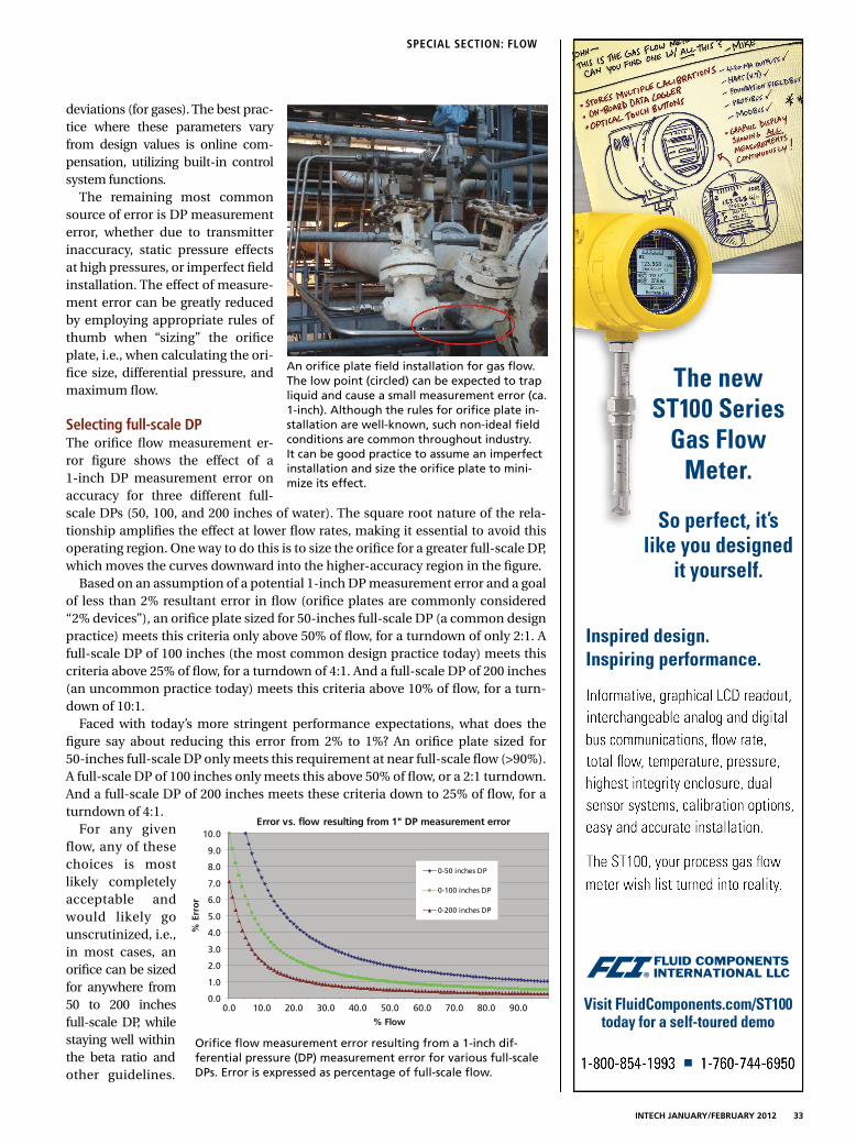
INTECH JANUARY/FEBRUARY 2012 33
SPECIAL SECTION: FLOW
deviations (for gases). The best prac-
tice where these parameters vary
from design values is online com-
pensation, utilizing built-in control
system functions.
The remaining most common
source of error is DP measurement
error, whether due to transmitter
inaccuracy, static pressure effects
at high pressures, or imperfect field
installation. The effect of measure-
ment error can be greatly reduced
by employing appropriate rules of
thumb when “sizing” the orifice
plate, i.e., when calculating the ori-
fice size, differential pressure, and
maximum flow.
Selecting full-scale DPThe orifice flow measurement er-
ror figure shows the effect of a
1-inch DP measurement error on
accuracy for three different full-
scale DPs (50, 100, and 200 inches of water). The square root nature of the rela-
tionship amplifies the effect at lower flow rates, making it essential to avoid this
operating region. One way to do this is to size the orifice for a greater full-scale DP,
which moves the curves downward into the higher-accuracy region in the figure.
Based on an assumption of a potential 1-inch DP measurement error and a goal
of less than 2% resultant error in flow (orifice plates are commonly considered
“2% devices”), an orifice plate sized for 50-inches full-scale DP (a common design
practice) meets this criteria only above 50% of flow, for a turndown of only 2:1. A
full-scale DP of 100 inches (the most common design practice today) meets this
criteria above 25% of flow, for a turndown of 4:1. And a full-scale DP of 200 inches
(an uncommon practice today) meets this criteria above 10% of flow, for a turn-
down of 10:1.
Faced with today’s more stringent performance expectations, what does the
figure say about reducing this error from 2% to 1%? An orifice plate sized for
50-inches full-scale DP only meets this requirement at near full-scale flow (>90%).
A full-scale DP of 100 inches only meets this above 50% of flow, or a 2:1 turndown.
And a full-scale DP of 200 inches meets these criteria down to 25% of flow, for a
turndown of 4:1.
For any given
flow, any of these
choices is most
likely completely
acceptable and
would likely go
unscrutinized, i.e.,
in most cases, an
orifice can be sized
for anywhere from
50 to 200 inches
full-scale DP, while
staying well within
the beta ratio and
other guidelines.
An orifice plate field installation for gas flow.
The low point (circled) can be expected to trap
liquid and cause a small measurement error (ca.
1-inch). Although the rules for orifice plate in-
stallation are well-known, such non-ideal field
conditions are common throughout industry.
It can be good practice to assume an imperfect
installation and size the orifice plate to mini-
mize its effect.
Error vs. flow resulting from 1" DP measurement error
0.0
1.0
2.0
3.0
4.0
5.0
6.0
7.0
8.0
9.0
10.0
0.0 10.0 20.0 30.0 40.0 50.0 60.0 70.0 80.0 90.0
% Flow
% E
rro
r
0-50 inches DP
0-100 inches DP
0-200 inches DP
Orifice flow measurement error resulting from a 1-inch dif-
ferential pressure (DP) measurement error for various full-scale
DPs. Error is expressed as percentage of full-scale flow.

34 INTECH JANUARY/FEBRUARY 2012 WWW.ISA.ORG
SPECIAL SECTION: FLOW
Consequently, based on an often arbitrary choice, turndown can
vary from 2:1 to 10:1, and accuracy from 4% or more to 1% or less.
Selecting maximum flow rateAnother often somewhat arbitrary choice in orifice sizing is
the maximum flow rate. As this discussion shows, selecting
an unnecessarily high maximum flow rate will compromise
accuracy at lower (normal) flow rates, so selecting a maxi-
mum flow rate based on infrequent conditions carries an
accuracy penalty under normal conditions and should be
avoided to the extent possible.
Many users do not realize that with modern smart trans-
mitters, which are configured by the end user, not calibrated,
the maximum flow measurement limitation is the upper
range limit (URL) of the transmitter (often 200 to 500 inches,
depending on the make and model), not the configured up-
per range value (URV), which is the orifice sizing full-scale
DP. This removes the incentive to increase the full-scale DP
in order to capture infrequent high flow conditions, since the
limitation is the transmitter URL, not the configured URV.
Taking advantage of this can have subtle and initially con-
fusing implications on traditional 4-20 milliamp analog input
systems, but on digital systems, such as Fieldbus, the practice
is simply to configure the control system “high” scale, or URV,
equal to the orifice sizing full-scale DP, and set the control
system “extended” scale based on the URL of the transmitter.
This practice allows the orifice sizing full-scale DP to be cho-
sen appropriately for normal conditions, thereby maximiz-
ing accuracy, while taking advantage of the full measurement
range of the transmitter to capture infrequent high flow rates.
Modern safety systems also create increased incentive for
orifice plate accuracy. Safety system transmitters are tradi-
tionally given a reduced range in order to improve accuracy
around the trip setting. But in modern safety systems, de-
sign calls for the safety transmitters to have the same range
as the control system transmitter in order to provide diag-
nostic discrepancy alarms.
CaveatsThere are a few caveats to shrinking the orifice and increasing
the DP in order to improve accuracy, but they are not usually
significant. As mentioned, the beta ratio, which is the ratio of or-
ifice diameter to inside pipe diameter, should remain within the
established design range of ca. 0.3 to 0.7. The table shows increas-
ing the full-scale DP from 50 to 200 inches will decrease the beta
ratio from ca. 0.60 to 0.45, still well within range on both ends.
Second, there can be an energy penalty for increased per-
manent pressure loss, which is typically 50–90% of DP. This
amounts to ca. 3 PSIG additional loss when switching from
100 to 200 inches full-scale DP, when at full-scale flow. In
most cases, this is not significant, and the pressure is lost
elsewhere in the process, for example, across a control valve.
Third, with a higher DP, there is the possibility of cavitation
or flashing in liquid service. This is not usually an issue and is
typically flagged by the orifice sizing software.
New rules of thumbFor greater orifice plate accuracy and turndown, use a larger
full-scale DP. Consider using 200 inches as a default, rather
than 50 or 100 inches.
Avoid selecting an unnecessarily high maximum flow for
sizing. Utilize the capabilities of modern smart transmitters
to capture infrequent high flow rates.
Use the figure to gauge if expected accuracy and turndown
are satisfactory, or if improvements could be easily captured
by selecting a higher full-scale DP.
ABOUT THE AUTHOR
Allan Kern ([email protected]) has 30+ years of experience
in process control and has authored numerous papers on multi-
variable control, inferentials, decision support systems, safety in-
strumented systems, distillation control, and other topics, with an
emphasis on practical process control effectiveness. Kern is a pro-
fessional control systems engineer in California, a senior member
of ISA, and a member of the InTech editorial advisory board.
View the online version at www.isa.org/intech/20120206.
Full-scale DP Beta ratioIncrease in permanent
pressure drop
50 inches 0.60
100 inches 0.52 1.6 PSIG
200 inches 0.45 3.2 PSIG
Effect of full-scale DP on beta ratio and permanent pressure drop

INTECH JANUARY/FEBRUARY 2012 35
ways to grow their business. It is telling that a com-
pany like Taiwan Semiconductor (TSMC) has written
in its corporate core values statement, a rejection of
“connections or guan-xi” in its hiring and business
practices. So things are changing—that’s not news,
but for those still contemplating working with Chi-
nese companies, what used to seem like challenges
specific to China, today seem much more like typi-
cal business challenges we face at the home office.
On the supply side, for companies who are not
considering China-based operations, today, one finds
many Chinese companies who will act as an interme-
diary between Western and Chinese manufacturers.
These brokers will take a set of drawings and speci-
fications, and find local vendors with the technical
capabilities, quality control, and capacity, to fit their
Western partner’s requirements. They handle all com-
munications and negotiations with vendors, monitor
vendor on-time delivery and quality, and often have
their own engineering staff and Q.C. labs. Compa-
nies like this come to the table with an answer to the
negative perceptions of Chinese quality, and with a
solution for companies lacking the resources to go
it alone. The reality today is we get excellent quality
from our Chinese sources—though as at home, the
process requires monitoring and management.
For anyone in charge of international sales or
sourcing, remember your managers still have a job
to do: setting expectations with suppliers; finding
common ground with sales partners; working a
game plan. Consider, when it comes to China, are
your managers at risk of perpetuating their own ste-
reotypes? Is potential China business getting short-
changed at your company because of what manag-
ers think they know about it? In China, as in other
overseas markets, insist managers remain focused on
the business and business goals, and that they work
at clear communications with their foreign coun-
terparts. Know small and mid-size companies have
more options than ever, to help ensure an investment
in China pays off. In the long run, managers will tend
to find that while some “secrets” may persist, they
need not be a barrier to success.
ABOUT THE AUTHOR
John Erskine ([email protected]) is a
vice president at Racine Federated Inc., manufac-
turer of flowmeters of various technologies includ-
ing ultrasonic, turbine, vortex-shedding, differen-
tial pressure, and variable area.
When the subject of China comes up, I often ask peo-
ple if they remember that 1970’s Calgon detergent
commercial: Mr. Lee’s customer asks him how he gets
the laundry so clean; his sly reply: “Ancient Chinese
secret!” The ad depicts stereotypes that simply would
not get air time today. Yet, when reviewing recent
publications or forums on doing business in China,
one finds plenty of comments that sound less like ac-
tionable advice, and more like ancient Chinese secrets:
■ Discussion threads on Asia/Pacific business,
where posts make mention of China’s invention
of the umbrella and gunpowder
■ Experts on China business who emphasize the
country’s 5,000-year history
■ And a favorite: The admonishment that Western-
ers must learn to discern “when yes really means
no.” Do Chinese authors warn their readers to
“beware the Socratic Method?”
It is not that these observations are wrong, but I
remain surprised at the relevance that gets ascribed
to them in the context of doing business with Chi-
nese companies today. For the executive whose
managers travel to China for growing sales or for
establishing sources of supply, a more practical ap-
proach is warranted. An approach focused on iden-
tifying similarities and aligned goals, tends to work
in China as it does at home.
For a small or mid-size manufacturer, doing business
in China today has never been easier. When we meet
with dealers, it is more common to see a corporate
mission statement in the office. Meetings are focused
on sales development the way Western-trained man-
agers understand it: where the dealer sees his role in
the value chain as providing market data, appointing
product champions, expanding geographic coverage,
and investing in local service and support capabili-
ties. Today, it is common to meet Chinese managers
with business degrees from the U.S. or Canada. With
a baseline relationship established with a solid dealer
who truly speaks our language, it means we can focus
energies on strategic goals—growing market share
and offering a product suite with the broadest appeal
to the local Chinese market.
Another observation: Today when visiting in China,
we are not lectured on the “importance of guanxi.”
(Guanxi xue involves the exchange of gifts, favors,
and banquets; the cultivation of personal relation-
ships and networks of mutual dependence.) It is not
that this idea has disappeared from Chinese culture,
but perhaps more managers there have found other
A China perspective for 2012 By John Erskine III
Tips and Strategies for Managers | executive corner

36 INTECH JANUARY/FEBRUARY 2012 WWW.ISA.ORG
Nearly every automation system sup-
plier, consultant, control theory pro-
fessor, and user has a favorite set
of PID tuning rules. Many of these experts
are convinced their set is the best. A hand-
book devoted to tuning has over 500 pages
of rules. The enthusiasm and sheer number
of rules is a testament to the importance of
tuning and the wide variety of application
dynamics, requirements, and complications.
The good news is these methods converge
for a common objective. The addition of
PID features, such as setpoint lead-lag, dy-
namic reset and output velocity limits, and
intelligent suspension of integral action en-
able the use of disturbance rejection tuning
to achieve other system requirements, such
as maximizing setpoint response, coordinat-
ing loops, extending valve packing life, and
minimizing upsets to operations and other
control loops.
Potential performance
The purpose of a control loop is to reject
undesired changes, ignore extraneous
changes, and achieve desired changes,
such as new setpoints. PID control provides
the best possible rejection of unmeasured
disturbances (regulatory control) when
properly tuned. The addition of a simple
deadtime block in the external reset path
can enhance the PID regulatory control ca-
pability more than other controllers with
intelligence built-in to process dynamics,
such as model predictive control. In plants,
unknown and extraneous changes are a
reality, and the PID is the best tool if prop-
erly tuned. The test time has been signifi-
cantly reduced for the most difficult loops.
Simple equations have been developed to
estimate tuning and resulting performance
for a unified approach. (Equation deriva-
tions and a simple tuning method are in
the online version.)
Control requirements
The foremost requirement of a PID is to
prevent the activation of a safety instru-
mentation system or a relief device and the
prevention of an environmental violation
(RCRA pH), compressor surge, and shut-
down from a process excursion. The peak
error (maximum deviation from setpoint) is
the most applicable metric. The most dis-
ruptive upset is an unmeasured step dis-
turbance that would cause an open loop
error (Eo) if the PID was in manual or did
not exist. The fraction of open loop error
seen in feedback control is more depen-
dent upon the controller gain than the
integral time since the proportional mode
provides the initial reaction important for
minimizing the peak error. Equation (1)
shows if the product of the controller gain
(Kc) and open loop gain (K
o) is much great-
er than one, the peak error (Ex) is signifi-
cantly less than the open loop error. The
open loop gain (Ko) is the product of the
final element, process, and measurement
gain and is the percent change in process
variable divided by the percent change in
controller output for a setpoint change.
For most vessel and column temperature
and pressure control loops, the process
rate of change is much slower than the
deadtime. Consequently, the controller
gain can be set large enough where the
denominator becomes simply the inverse
of the product of the gains. Conversely,
for loops dominated by deadtime, the de-
nominator approaches one, and the peak
error is essentially the open loop error.
(1) o
oc
x EKK
E ∗∗+
=)1(
1
The peak error is critical for product
quality in the final processing of melts,
solids, or paste, such as extruders, sheet
lines, and spin lines. Peak errors show
up as rejected product due to color, con-
sistency, optical clarity, thickness, size,
shape, and in the case of food, palatabil-
ity. Unfortunately, these systems are dom-
inated by transportation delays. The peak
errors and disruptions from upstream pro-
cesses must be minimized.
The most widely cited metric is an inte-
grated absolute error (IAE), which is the
area between process variable and the
setpoint. For a non-oscillatory response,
the IAE and the integrated error (IE) are
the same. Since proportional and integral
action are important for minimizing this
error, Equation (2) shows the IE increases
as the integral time (Ti) increases and the
controller gain decreases.
(2) o
co
fxi
i EKK
tTE ∗
∗
+D+=
)( t
Equation (2) also shows how the IE
increases with controller execution time
(Dtx) and signal filter time (t
f). The equiva-
lent deadtime from these terms also de-
creases the minimum allowable integral
time and maximum allowable controller
gain, further degrading the maximum
possible performance. In many cases, the
original controller tuning is slower than
allowed and remains unchanged, so the
only deterioration observed is from these
terms in the numerator of Equation (2).
Studies on the effect of automation sys-
tem dynamics and innovations can lead
to conflicting results because of the lack
of recognition of the effect of tuning on
automation basics | Loop Tuning
PID tuning rules By Greg McMillan
Safety, equipment and environmental protection, process
efficiency and capacity, product quality, and control system
maintenance depend on PID tuning.n Peak error, integrated error, and rise
time are inversely proportional to PID
gain.
n A unified equation for PID gain is ap-
plicable to all major types of processes.
n PID features can inherently prevent
cycling without retuning.
Fast Forward

Loop Tuning | automation basics
INTECH JANUARY/FEBRUARY 2012 37
the starting case and comparative case
performance. In other words, you can
readily prove anything you want by how
you tune the controller.
IE is indicative of the quantity of product
that is off-spec that can lead to a reduced
yield and higher cost ratio of raw material
or recycle processing to product. If the off-
spec cannot be recycled or the feed rate
cannot be increased, there is a loss in pro-
duction rate. If the off-spec is not recover-
able, there is a waste treatment cost.
A controller tuned for maximum per-
formance will have a closed loop re-
sponse to an unmeasured disturbance
that resembles two right triangles placed
back to back. The base of each triangle is
the total loop deadtime and the altitude
is the peak error. If the integral time (reset
time) is too slow, there is slower return
to setpoint. If the controller gain is too
small, the peak error is increased, and
the right triangle is larger for the return
to setpoint.
Process dynamics
The major types of process dynamics are
differentiated by the final path of the open
loop response to a change in manual con-
troller output assuming no disturbances.
(The online version shows the three major
types of responses and the associated dy-
namic terms.) If the response lines out to
a new steady state, the process is self-reg-
ulating with an open loop time constant
(to) that is the largest time constant in
the loop. Flow and continuous operation
temperature and concentration are self-
regulating processes. If the response con-
tinues to ramp, the process is integrating.
Level, column and vessel pressure, batch
operation temperature, and concentration
are integrating processes. If the response
accelerates ,reaching a point of no return,
the process has positive feedback leading
to a runaway. Batch or continuous temper-
ature in highly exothermic reactors (e.g.,
polymerization) can become runaway
processes. Prolonged open loop tests are
not permitted, and setpoint changes are
limited. Consequently, the acceleration is
rarely intentionally observed.
Unified approach
The three major types of responses have
an initial period of no response that is
the total loop deadtime (qo) followed by
the ramp before the deceleration (inflec-
tion point) of a self-regulating response
and the acceleration of the runaway re-
sponse. The percent ramp rate divided by
the change in percent controller output
is the integrating process gain (Ki) with
units of %/sec/%, which reduces to 1/sec.
For at least 10 years, slow self-regulating
processes with a long time to deceleration
have shown to be effectively identified
and tuned as “near integrating” or “pseu-
do integrating” processes, leading to a
“short cut tuning method” where only
the deadtime and initial ramp rate need
to be recognized. The tuning test time for
these “near integrating” processes can be
reduced by over 90% by not waiting for
a steady state. Recently, the method was
extended to runaway processes and to
deadtime dominant self-regulating pro-
cesses by the use of a deadtime block to
compute the ramp rate over a deadtime
interval. Furthermore, other tuning rules
were found to give the same equation for
controller gain when the performance ob-
jective was maximum unmeasured distur-
bance rejection. For example, the use of
a closed loop time constant (λ) equal to
the total loop deadtime in Lambda tuning
yields the same result as the Ziegler Nichols
(ZN) ultimate oscillation and reaction curve
methods if the ZN gain is cut in half for
smoothness and robustness. Equation (3)
shows the controller gain is half the in-
verse of the product of integrating process
gain and deadtime.
(3)
oi
c
KK
q∗=
5.0
The profession realizes that too large
of a controller gain will cause relatively
rapid oscillations and can instigate insta-
bility (growing oscillations). Unrealized for
integrating process is that too small of a
controller gain can cause extremely slow
oscillations that take longer to decay as
the gain is decreased. Also unrealized for
a runaway process is that a controller gain
set less than the inverse of the open loop
gain causes an increase in temperature to
accelerate to a point of no return. There
is a window of allowable controller gains. The effect of integral time on the maximum possible disturbance rejection

automation basics | Loop Tuning
38 INTECH JANUARY/FEBRUARY 2012 WWW.ISA.ORG
Also realized is too small of an integral
time will cause overshoot and can lead to
a reset cycle. Almost completely unrealized
is that too slow of an integral time will re-
sult in a sustained overshoot of a setpoint
that gets larger and more persistent as the
integral time is increased for integrating
processes. Hence a window of allowable
integral times exists. Equation 4a provides
the right size of integral time for integrat-
ing processes. If we substitute Equation 3
into Equation 4a, we end up with Equation
4b, which is a common expression for the
integral time for maximum disturbance re-
jection. Equation 4a is extremely important
because most integrating processes have
a controller gain five to 10 times smaller
than allowed. The coefficient in Equation
4b can be decreased for self-regulating
processes as the deadtime becomes larger
than the open loop time constant (to) esti-
mated by Equation 5.
(4a)
)(
2
ic
i
KKT
∗=
(4b) oi
T q∗=4
(5)
i
o
o
K
K=t
The tuning used for maximum load re-
jection can be used for an effective and
smooth setpoint response if the setpoint
change is passed through a lead-lag. The
lag time is set equal to the integral time,
and the lead time is set approximately
equal to ¼ the lag time.
For startup, grade transitions, and op-
timization of continuous processes and
batch operations, setpoint response is im-
portant. Minimizing the time to reach a
new setpoint (rise time) can in many cases
maximize process efficiency and capacity.
The rise time (Tr) for no output saturation,
no setpoint feedforward, and no special
logic is the inverse of the product of the
integrating process gain and the controller
gain plus the total loop deadtime. Equation
6 is independent of the setpoint change.
(6) o
ci
r
KKT q+
∗=
)(
1
Complications, easy solutions
Fast changes in controller output can cause
oscillations from a slow secondary loop or
a slow final control element. The problem
is insidious in that oscillations may only
develop for large disturbances or large
setpoint changes. The enabling of the
dynamic reset limit option and the timely
external reset feedback of the secondary
loop or final control element process vari-
able will prevent the primary PID control-
ler output from changing faster than the
secondary or final control element can re-
spond, preventing oscillations.
Aggressive controller tuning can also
upset operations, disturb other loops,
and cause continual crossing of the split
range point. Velocity limits can be added
to the analog output block, the dynamic
reset limit option enabled, and the block
process variable used as the external reset
to provide directional move suppression
to smooth out the response as necessary
without retuning.
The different closed loop response of
loops can reduce the coordination, espe-
cially important for blending and simplifi-
cation of the identification of models for
advanced process control systems that ma-
nipulate these loops. Process nonlinearities
may cause the response in one direction to
be faster. Directional output velocity lim-
its and the dynamic reset limit option can
be used to equalize closed
loop time constants with-
out retuning.
Final control element
resolution limits (stick-slip)
and deadband (backlash)
can cause a limit cycle if
one or two or more inte-
grators, respectively, exist
in the loop. The integrator
can be in the process or in
the secondary or primary
PID controller via the inte-
gral mode. Increasing the
integral time will make
the cycle period slower
but cannot eliminate the
oscillation. However, a to-
tal suspension of integral
action when there is no
significant change in the
process variable and when
the process is close to the
setpoint can stop the limit cycle. The out-
put velocity limits can also be used to pre-
vent oscillations in the controller output
from measurement noise exceeding the
deadband or resolution limit of a control
valve preventing dither, which further re-
duces valve wear.
Bottom line
Controllers can be tuned for maximum
disturbance rejection by a unified meth-
od for the major types of processes. PID
options in today’s DCS, such as setpoint
lead-lag, directional output velocity limits,
dynamic reset limit, and intelligent sus-
pension of integral action, can eliminate
oscillations without retuning. Less oscilla-
tions reduces process variability, enables
better recognition of trends, offers easier
identification of dynamics, and provides
an increase in valve packing life.
ABOUT THE AUTHOR
Greg McMillan (Greg.McMillan@Emerson.
com) is a retired Senior Fellow from So-
lutia-Monsanto and received the ISA Life
Achievement Award in 2010. Presently, he
is a principle consultant with CDI Process &
Industrial contracting at Emerson Process
Management in DeltaV R&D. He is also a
part-time employee of MYNAH Simulation
Technologies in Saint Louis.

To learn more about Honeywell field solutions, please call
1-877-466-3993 or visit www.honeywell.com/ps/hfs
© 2011 Honeywell International, Inc. All rights reserved.
right bait
Honeywell has the right bait for any
catch – large or small.
Reliable and cost-effective, we offer a constantly expanding
portfolio of field solutions to satisfy a broad range of your
process needs. From analytical sensors and transmitters, to
pressure and temperature transmitters, to flow and modular
controllers. Ho neywell offers fit-for-purpose solutions. Honeywell’s collection of field
solutions let you tackle any job with ease to improve business performance.

40 INTECH JANUARY/FEBRUARY 2012 WWW.ISA.ORG
Getting involved with an ISA section By Mat Merten
I have gained a tremendous
amount, professionally and more
important personally, from being
involved in technical societies.
she said she would be there. We met the next day,
and I showed her around the floor and pits. At that
moment, she was hooked, and we both committed
to starting a team at Annoor.
Starting a FIRST team is tough, but after many long
meetings, parental discussions, fundraising (yes, the
ISA Oak Ridge Section is an official sponsor), table
building, field trips, and robot troubleshooting, we
have a team we literally could not be more proud
of. Only in elementary school, the children have
learned and come together as a team beyond our
wildest expectations. We have appointed a Team
Captain, Hardware Captain, Software Captain, and
Project Captain. These children have already learned
about many valuable technical topics from motors,
power, trigonometry, to even food safety, which
was the theme the kids had to research in 2011.
Outside the world of the team, the kids have more
self-confidence with their new technical prowess,
and they are envied by their classmates who are not
on the team. Each has taken incredible ownership,
and we are so proud of them.
Two main points: I have gained a tremendous
amount, professionally and more important per-
sonally, from being involved in technical societies.
Being a coach of a robotics team has been simply
a wonderful experience, and there is no way this
chain of events would have occurred if not for ISA
and working with many other people. Second, the
local ISA Sections can be a force of good in the
community, not only from a technical and business
knowledge sharing standpoint, but also from a giv-
ing back to the community standpoint.
The Oak Ridge Section may not be the best ISA
section out there, but it is improving. Our goals
for 2012 are to have a high-quality website, host
a vendor’s fair, present 10 technical presenta-
tions, and my personal favorite, become the of-
ficial sponsors of multiple FIRST Robotics teams
throughout the community. We are getting there
and encourage others to get involved with their
local ISA sections as well.
ABOUT THE AUTHOR
Mat Merten, P.E., is the Federal/Nuclear Engineer-
ing manager for BESCO in Oak Ridge, Tenn. He is
involved in various organizations throughout the
community and is the most passionate about his
Robot Kids.
In January 2009, I became a licensed engineer. Af-
ter the excitement wore off, I became concerned
about how to get all my needed professional de-
velopmental hours (PDH). Although a member of
ISA, I was not involved in the local section in Oak
Ridge, Tenn., nor had I heard about anything go-
ing on with the section. I reached out to some of
the local officers I found on the website and said I
wanted to get involved. After meeting with the of-
ficers, we decided to kick-start the Oak Ridge Sec-
tion and have monthly technical meetings. I volun-
teered to be the program chair, which essentially
meant I became the face of the section.
The first few meetings were rough. Few people
came, and the section was going through a lot
of cash. However, we kept at it, and after a year,
we got momentum going in the community, and
now have upwards of 40 participants. Speakers
have started reaching
out to us because they
know they will have a
captive audience. We are
really proud of how far
the Oak Ridge Section
has come.
Since this section began, I have personally gotten
involved in FIRST Robotics, thanks to having attend-
ed ISA Automation Week 2010, where the keynote
speaker, FIRST founder Dean Kamen, sparked my
interest. A few months after that event, I was noti-
fied by the National Society of Professional Engineers
(NSPE), another technical society that I am a member
of, that a local regional competition of FIRST Robot-
ics was going to be held in Knoxville, Tenn. In just a
few days, I convinced the regional director that since
I helped run the local section of ISA, I would be an
excellent choice for a judge. The director agreed.
A judge’s commitment is Thursday evening and all
day Friday and Saturday. After spending 30 seconds
on the game floor Thursday evening, I knew this
event was an incredible opportunity and immediately
thought it would be perfect for Amber Hodge, a
marvelous teacher I previously had met while judging
a science fair at a local Islamic school, Annoor Acad-
emy. (I learned about the science fair through yet an-
other organization—the American Nuclear Society.) I
was not able to contact Hodge until late Friday night,
but sent her an e-mail anyway telling her she had to
come and see it herself. My expectations were low
that she would come since it was so last minute, but
young innovators | Talking Shop with the Next Generation

at the ultimate conference for automation professionals—
ISA Automation Week: Technology and Solutions Event
GATHERLEARNTHRIVE
AutomationWeek Technology and
Solutions Event24–27 September 2012Orange County Convention CenterOrlando, Florida USA
www.isaautomationweek.org/2012
I’ll be there to network,learn from technical
and business sessions,and meet with my suppliers.
See you there!
ISA Corporate Partners
ISA Strategic Partner, Test and Measurement
Call for Papers Share your expertise! Submit an abstract by 5 March 2012.

association news | Highlights and Updates
42 INTECH JANUARY/FEBRUARY 2012 WWW.ISA.ORG
2011 was a busy year for me as the ISA
President-elect and went by quickly. I
was honored to attend multiple ISA
events, including division symposia, sum-
mits, leadership conferences, section meet-
ings, and numerous web meetings and
teleconferences. These events opened op-
portunities for me to interact with hundreds
of ISA members and witness the amazing
depth and breadth of knowledge they have
to offer the automation community. As a
Society, we are indeed setting the standard
for automation throughout the world.
As your 2012 ISA President, my main fo-
cus will be to provide tangible benefits for
ISA members and to be instrumental in the
continued advancement of the practice of
automation. My focus aligns with the Soci-
ety’s 2012–2015 strategic goals:
■ Serve students, professionals, and in-
dustry by delivering knowledge resourc-
es via publications, conferences and ex-
hibits, training, and other programs.
■ Develop globally recognized standards,
publications, and certifications for the
automation community.
■ Attract and retain automation profession-
als as members and customers worldwide.
To make these goals a reality, we must
continue to provide current technical con-
tent to support ISA’s technical conferenc-
es and events, actively support divisions,
strengthen sections, and offer exception-
al programs to automation professionals.
ISA is committed to enhancing its
position as the source for authoritative
standards and practices in all automa-
tion areas. We can benefit from initiating
discussions with other professional orga-
nizations to understand how to make ac-
cess to ISA standards for their members
more applicable to them. For example:
■ Collaborating with the leaders of automa-
tion companies and educational providers
to encourage wider acceptance and usage
of ISA standards as part of their culture
■ Working with political entities to raise
awareness of the availability and appli-
cability of ISA standards to government
procurement policies
ISA offers excellent certification pro-
grams, but they do not have wide-spread
acceptance throughout the automation
profession. I plan to establish a special task
force to market these programs to indus-
try, government, and educational institu-
tions. I would like to reach the point where
holding an ISA certification becomes a
standard requirement in the automation
field, much like the Project Management
Professional (PMP) has become for Project
Management.
In the coming years, the Society has a
number of training and educational goals.
We will continue expanding our effort to
establish community college, undergradu-
ate, and graduate degree programs in Au-
tomation Studies as part of the Engineer-
ing Curriculum. ISA will push forward with
providing flexible, affordable training pro-
grams that best serve individual and com-
pany needs. The Society will also look at
how companies are training their automa-
tion engineers and technicians and discuss
ways to implement its own programs that
will augment companies’ existing training.
Last, but certainly not least, ISA Web
2.0 needs to be a portal to the technical
world, while maintaining trusted content.
Last summer, the first steps were taken
with the roll out of ISA Interchange, and
a larger conversation began between au-
tomation professionals on vehicles such as
Twitter, Facebook, and LinkedIn. ISA an-
ticipates the technical posts and conversa-
tions will continue to thrive going forward.
Meeting our goals will take all of us work-
ing together. I urge you to contribute as an
individual, section, district, division, depart-
ment member, and leader to help strengthen
ISA. As you develop plans and consider op-
tions in your role as an ISA volunteer, please
keep these two questions in mind:
■ How are we benefitting our members?
■ How are we advancing the practice of
automation?
I look forward to working with each of
you in 2012 and encourage your input.
Working together, we can set the stan-
dard for automation.
ABOUT THE AUTHOR
Robert E. Lindeman, CAP, PMP, is the 2012
ISA President.
Path set for 2012
By Robert E. Lindeman
Memoriam: Hugh Wilson1978 ISA President Hugh Wilson passed away late last year. Wilson was 85. A memorial
service was held in early January. Wilson was an icon of Moore Products Co. He started
in Chicago as a young sales engineer and quickly moved to branch manager. He raised
his hand and said he would take over DuPont, which was a stagnant account for Moore
for many years. Hugh eliminated all sales credit for himself and started visiting DuPont
sites teaching control theory courses at the sites. He started U.K. operations, then Canada,
South Africa, Asia Pacific, and other areas of the world. Wilson retired as vice president,
International Sales/Operations. Wilson held many important roles in ISA, none more impor-
tant as ISA President. In all the years he was active in ISA, he never lost sight of the fact that
he worked for Moore Products, and so many of his successes in setting up international
operations was a result of his networking at ISA.
Memoriam: Ernie MagisonErnest Carroll Magison was born 15 October 1926 and died on 3 December 2011 in
Tampa, Fla. He was 85. He was a published author for ISA, authoring Electrical Instru-
ments in Hazardous Locations. Magison was active in standards development at ISA, IEC,
and NFPA for four decades. He has authored 40 articles, as well as papers and several
books. Magison worked as an electrical engineer for Honeywell for 33 years and as a
professor at Drexel University in Philadelphia for 15 years concurrently. He is survived by
his wife of 28 years, Dixie, six daughters, and two stepdaughters.

Learn more: fl uke.com/pressure
Fluke Pressure Gauges: Accurate. Easy to use. Tough.
The new 700G Series Pressure Test Gauges offer
best-in-class accuracy and measurements for all
your pressure needs. Add the Fluke 717 or 718
Pressure Calibrators with newly improved
accuracy and you’ve got a family of tools that
don’t just measure pressure. They take it.

44 INTECH JANUARY/FEBRUARY 2012 WWW.ISA.ORG
unambiguous. Systems must be designed
so the controller will not act too early
when a problem arises but has sufficient
time to diagnose and determine what
specific action is required, with enough
of a cushion for the process to respond.
Reconsidering SCADA
Historically, we think of SCADA as com-
munications and wiring bringing signals
to a display. As an industry, we have not
given much thought to the operator in-
terface. SCADA is a complex toolset, in-
cluding multiple software components
and communications technologies, com-
plex networking, and field equipment. To
have a firm grasp on the entire system,
the pipeline operator needs a well-docu-
mented data flow and infrastructure.
What often is missing in these systems
is a way to record shift handover and
controllers’ logs, as well as processes for
alarm management, simulation training,
leak detection modeling, commissioning
support, and change management. In ad-
dition, some rework—in the way data is
displayed on the HMIs and the way the
alarms are processed—is needed. Some of
these changes may be strictly procedural,
some may entail software updates, and
some may require a combination of both.
Compliance is opportunity
Addressing this new rule offers the pipe-
line operator a prime opportunity to take
a structured approach to best practices
that will significantly improve their op-
erations. The requirements will drive a re-
work of displays, alarms, and procedures.
Doing this incrementally will require a
very thoughtful approach to the disci-
plined methodology.
ABOUT THE AUTHOR
Russel Treat ([email protected]) is
founder and president of EnerSys Corpo-
ration, a Control System Integrators As-
sociation Certified member.
load or confusion. Current control rooms
are generally designed for normal opera-
tions. However, it is during abnormal or
emergency operations when proper hu-
man factors engineering can make the
difference between success and failure.
Fundamental to success are two key
concepts: “situational awareness” and
“permission to operate.” Originally a
battlefield science, situational awareness,
as applied to control systems, refers to a
single display that quickly provides the
operating condition of the pipeline: nor-
mal, abnormal, or emergency.
The second key concept in our approach
is permission to operate. The premise is you
maintain permission to operate as long as
you maintain situational awareness (i.e.,
you understand the operating condition).
When you lose situational awareness, then
you no longer have permission to oper-
ate and need to return to a safe operat-
ing condition. This could require shutting
down or changing operating parameters,
depending on the process.
Frequently, a process moves from nor-
mal operations into abnormal operations
before the controller receives any notifi-
cation. The idea is to design displays to
show abnormal operations before an
alarm is required. Then, use alarms levels
to ensure the operator has time to prop-
erly identify the cause, determine the so-
lution, take corrective action, and allow
for the process to respond.
Our recommended best practice is
to define alarm as something requiring
controller action. Further, EnerSys recom-
mends pre-engineering all alarms and
making the results available to improve
the controller’s ability to accurately re-
spond. Because field personnel may be
required to drive to remote sites to handle
manual portions of the process, planning
for elapsed time is critical to success.
Retaining permission to operate re-
quires implementing alarm management
in such a way that alarms are clear and
Many pipeline operators will
spend substantial time and ef-
fort reworking their control
rooms and systems to comply with the new
Pipeline Hazardous Materials Safety Admin-
istration’s (PHMSA) Control Room Manage-
ment (CRM) rule by 1 August 2012. With a
small amount of additional effort, pipeline
operators can leverage compliance efforts
into best practices that will serve them now
and well into the future.
Why the new rule?
In investigating incidents, PHMSA found
pipeline controllers (the person using the
Supervisory Control and Data Acquisition
[SCADA] system) may be qualified but not
always successful in managing abnormal
situations or events. The controller’s ability
to manage abnormal situations can be influ-
enced by ineffective procedures, fatigue, or
even limitations in the SCADA system itself.
To comply with the CRM rule, pipeline
operators must:
■ Provide effective operating and main-
tenance procedures, including specific
requirements for training
■ Match the control room environment
and equipment (including displays,
alarming, environment, etc.) to human
capability
■ Provide controllers with warnings and
guidance when abnormal operations
occur
The requirement to “match to human
capability” presents one of the greatest
challenges to pipeline operators, demand-
ing solutions and systems that differ sig-
nificantly from anything they have in their
control rooms today.
Situational awareness, permission
to operate
Matching a control room to human ca-
pability is the science of human factors.
The idea is to provide the information re-
quired to maintain pipeline safety and op-
erational control without too much work-
channel chat | Tips and Strategies for Systems Integrators
Compliance with new pipeline rule offers opportunity to implement best practices By Russel Treat

Today’s only existing pinch-valve
standards (from ISA) capture years
of success to save time and cost for
instrument engineers and designers who
use these standards in projects related to
pinch-valve design, engineering, construc-
tion, installation, commissioning, and main-
tenance. Pinch-valve standards can increase
efficiency, productivity, and reliability in
plant operations and provide safety to the
users and their equipment in application of
pinch valves. Yet there is some discrepancy
between the existing definitions in ANSI/ISA-
75.05.01, Control Valve Terminology, and
the draft standard ISA-75.10.03, Installed
Face-to-face Dimensions for Shell and Tube
Flanged Pinch Valves. Here is a history and an
explanation of the need for change.
Pinch-valve uses
Historically, the rubber/elastomer sleeve
(bladder) and lining allowed pinch-valve
manufacturers more freedom with elas-
ticity and isolation to design pinch valves
and create face-to-face dimensions for
their valves than those manufacturers of
conventional control valves.
Elasticity is a property of the rubber/
elastomer that allows bubble-tight sealing
and shut-off, as well as some flexibility in
designing the overall valve body length.
The term “soft face-to-face dimension”
refers to the linear dimension from the
far left side of one flange of a pinch valve
to the far right side of the other flange
before installation of the valve into the
piping system, i.e., when the rubber/elas-
tomer sleeve and the elastic lining on the
flanges have not been compressed.
Isolation is not a property of the rubber/
elastomer, but manufacturers can achieve
complete isolation of the process medium
from the valve body with the rubber/elas-
tomer sleeve in pinch valves. Certain pinch-
valve designs have mesh wires (sensors)
built inside the sleeve for leak-detection
in the process. When the sleeve starts to
break, such sensors monitor early leaks be-
fore breaks are complete.
Another reason pinch valves have their
own face-to-face dimensions is they handle
fluids conventional control valves could not
handle, such as corrosives (acids and caustics
used in water treatment/chemical plants),
slurries (from sewage systems), and abrasive
solids (coarse sands in mining).
Standardization
There was no standard stipulating what rub-
ber/elastomer material to use for specific
fluids in the 1950s; only guidelines existed.
While some of the properties overlap each
other, pinch-valve manufacturers have their
own successful, but untold, stories related to
solving unique problems. Pinch valves came
into being when engineers saw conventional
control valves could not handle corrosives,
slurries, and abrasive solids. The engineers
worked on their own drawing boards, se-
lected their own rubber/elastomers, and
built their own valves. Yet not all pinch-valve
manufacturing achieved success, and some
pinch valves disappeared from the market.
This is why there are five columns of face-
to-face dimensions in the current draft stan-
dard ISA-75.10.02, Installed Face-to-Face
Dimensions for Dual Pinch Flanged Clamp
or Pinch Valves (Classes 125 and 150), and
four columns of face-to-face dimensions in
ISA-75.10.03.
Need for re-defining
The objective of having a standard is not
the same as providing one fixed set of face-
to-face dimensions for all pinch valves. A
standard of face-to-face dimensions can
have various sets of dimensions, such as
ASME/ANSI B16.10, which has 20 differ-
ent columns of face-to-face dimensions.
Furthermore, having a standard does not
mean the standard can never be changed.
One view is shell-and-tube pinch valves
are on-off valves, without a physical actua-
tor for their operation, and perhaps should
not be considered as a control valve under
the definition in ANSI/ISA-75.05.01.
Another view, that of the ISA75.10 sub-
committee, is control valves and actuators
need to be redefined in broader terms. First,
on-off control is a type of process control.
Second, current literature illustrates how
shell-and-tube pinch valves can be used
in throttling (modulating) control when
equipped properly with transmitters and
controllers, just like any control valve. Third,
the definition of control valves in ANSI/ISA-
75.05.01 is problematic. Under ANSI/ISA-
75.05.01, a control valve is defined as hav-
ing to have a physical actuator attached. This
is not practical in industry. Pressure-reducing
valves have no actuators, but they are still
control valves. Similarly, shell-and-tube pinch
valves are operated by a pressure signal; they
work without an actuator and can perform
modulating controls like a control valve. To
broaden the application of control valves,
the ISA75.05 subcommittee should revisit
the definitions of the terms “control valves”
and “actuators” in ANSI/ISA-75.05.01.
Thus, in ISA-75.10.03, control valves
and actuators are re-defined as described
above. Control valves are any valves oper-
ated by an instrument signal. Actuators
are transducers for converting instrument
signals to displacements. With these defi-
nitions in place, ISA75.10 can establish the
new ISA-75.10.03.
ABOUT THE AUTHOR
Gerald Liu, P.E. ([email protected]) is the
chairman of ISA75.10 and lives in Calgary,
Alberta, Canada. If you are interested in
joining the efforts of ISA75.10, contact him
or Ellen Fussell Policastro ([email protected].)
Change needed in pinch-valve standard definitionsBy Gerald Liu
A standard of face-to-face dimensions can have various sets of
dimensions, such as ASME/ANSI B16.10, which has 20 different
columns of face-to-face dimensions. Furthermore, having a
standard does not mean the standard can never be changed.
standards | New Benchmarks & Metrics
46 INTECH JANUARY/FEBRUARY 2012 WWW.ISA.ORG


48 INTECH JANUARY/FEBRUARY 2012 WWW.ISA.ORG
Ultrasonic flow measurement, loggingThe Ultrasonic Flow Measurement and Log-
ging Family, featuring advanced DSP technol-
ogy, includes two portable models, Portaflow
220 and 330, and two fixed installation mod-
els, Ultraflo 3000/4000. Both system types dis-
play instantaneous fluid flow rates or velocity
and totalized values and install quickly and eas-
ily without interrupting the process stream. The
systems’ data loggers can output data directly
to a PC or printer or store data in the instru-
ment’s memory for downloading at a later time.
The instruments incorporate ‘Transit-Time’ (time of flight) DSP measurement capability,
ideal for clean media and process liquids. These devices provide a sampling resolution
of 50 pico-second and continuous single level indication to the display. Other high
performance capabilities include a bi-directional velocity range of 0.33 ft/s, with maxi-
mum velocity of 65 ft/s with repeatability of ±0.5% of measured value or ±0.02m/s,
whichever is greater.
GF Piping Systems, www.gfpiping.com
products & resources | Hot Stuff for the Automation Market
Vortex shedding flowmetersThe CoolPoint vortex shedding flowmeters offer
Intrinsic Safety as an option. CoolPoint vortex shedding
flowmeters are electronic instruments that measure and
monitor water flows. Unlike mechanical switches, the vortex
shedding meters have no moving parts to stick or coat, eliminating
potential for clogging by particles. The Intrinsic Safety feature is available on 1/4”, 3/8”,
½”, 3/4”, 1”, 1 ½” and 2” CoolPoint meters. The transmitter with Intrinsic Safety is a
2 wire 4-20mA transmitter that has approved barriers and no display, alarm, or pulse
output. It conforms to requirements for NEC Class I, Division 1, Group D environments.
The standard CoolPoint flow rate transmitter is a 4-20 mA 3 wire transmitter, which
has the following standard feature and user-configurable options: Brass body with viton
seals and PVDF sensors; available in pipe sizes ranging from 1/4 inch to 4 inches; flow
repeatability is +/- .25% (1/4 of 1%); +/- 2% full-scale accuracy at maximum flow;
turndown ratio 10:1; and 3 wire 4-20 mA flow rate transmitter with visual 3-digit LED
readout, selectable alarm state (N.O. or N.C.), set point or pulse output and engineering
unit choice of GPM or LPM.
Universal Flow Monitors, www.flowmeters.com
Handheld thermometer
hygrometer data logger
The RHXL3SD Handheld Thermometer/Hy-
grometer Data Logger comes with a tem-
perature-humidity probe, 2GB SD card, and
features automatic temperature compensa-
tion for dew point, wet-bulb and thermo-
couple measurements, the ability to hold
readings and display maximum and mini-
mum readings, and an automatic power off
function that extends battery life. The back-
lit dual LCD display makes readings easy to
read. Ideal for clean rooms, greenhouses,
and pharmaceutical industries to monitor
the temperature and relative humidity.
Omega Engineering, www.omega.com
Test disconnect terminal blocks
The test disconnect terminal blocks save
space in the control cabinet while increas-
ing safety and reducing assembly time.
The UTME 4 series features pluggable
COMBI connectors in a compact 4 mm2
profile. The test disconnect blocks have
short-circuit plugs for a “make first, break
last” operation. This ensures the CT circuit
is shorted out prior to test and measure-
ment, preventing inadvertent actuation
and improving safety for the system and its
operators. The series’ narrow profile saves
cabinet space. A screw-free knife discon-
nect lever makes it easy to see the position
of the switch, and there are bridging chan-
nels on either side of the disconnect lever.
Phoenix Contact, www.phoenixcontact.com
Windjammer brushless DC blowers
Windjammer brushless DC blowers offer
compact, low-noise, and long-life solutions
and includes low-voltage and high-voltage
versions as well as bypass and thru-flow
products. Sizes range from 3.0” to 5.7” to
accommodate the most demanding design
envelopes and application requirements.
Low-voltage blowers (3.0”, 3.3”, 4.5”,
5.0”, 5.1”, and 5.7”) for vacuum or pres-
sure applications can deliver variable output
pressure up to 98 in. H2O and flows up to
190 CFM, depending on model, and high-
voltage versions (5.7”) can provide output
pressure up to 169 in. H2O and flows up
to 275 CFM. The blowers can accept volt-
age inputs of 12 VDC, 24 VDC, 48 VDC, 72
VDC, 120 VAC or 240 VAC.
AMETEK Technical & Industrial Products
www.ametektechnicalproducts.com
Gas turbine meterThe Blancett Gas QuikSert Turbine Flow Meter provides Blancett’s
accuracy and ruggedness in a unique wafer-style design that al-
lows for quick installation between two flanges. Gas QuikSert is
constructed from stainless steel and tungsten carbide, ensuring an
extended service life even in demanding oil and gas production
environments. Explosion proof and intrinsically safe ratings
allow QuikSert to be mounted in virtually all Class I Div
1 hazardous areas. With a lightweight rotor design that
provides instantaneous response to changes in flow, and
full compatibility with Blancett’s B2800 Flow Monitors,
K-Factor Scalers, Intelligent Converters, and the B3000 series of flow monitors, the Gas
QuikSert provides an option for gas flow measurement up to 350 CFM [600 m3/H].
Racine Federated Inc., www.racinefed.com/flow

INTECH JANUARY/FEBRUARY 2012 49
datafiles
Datafiles list useful
literature on prod-
ucts and services
that are available
from manufacturers
in the instrumenta-
tion and process-
control industry. To
receive free copies
of this literature,
please contact each
manufacturer via
their provided con-
tact information.
THERMOCOUPLE/VOLTAGE INPUT USB DATA ACQUISITION MODULE
Omega’s new OM-DAQ-USB-2401, USB 2.0 full speed thermocouple/voltage input data acquisition modules are fully compatible with both USB 1.1 and USB 2.0 ports. This module is user programmable for type J, K, T, E, R, S, B, N thermocouples or voltage input and features 8 differential or 16 single-ended analog inputs, 24 Bit Resolu-tion with up to 1000 Samples/Sec throughput. The module is powered directly by USB port or an External DC Power Supply and includes windows software, drivers for custom programming, and hardware for bench-top, DIN rail, or wall mounting. Models start at $495.
www.omega.com, [email protected] or 203-359-1660
InTech advertisers are pleased to provide additional
information about their products and services. To obtain further
information, please contact the advertiser using the contact information
contained in their ads or the web address shown here.
ad index
Advertiser Page #
Anton Paar �������������������������������������������������8
www.anton-paar.com
Arjay Engineering Ltd� ����������������������������23
www.arjayeng.com
c3controls ������������������������������������������������45
www.c3controls.com
CSA International �������������������������� Cover 3
www.gethazloc.com
www.csa-international.org
Emerson Process Management ����� Cover 4
www.emersonprocess.com
Fluid Components International (FCI)����33
www.fluidcomponents.com
Fluke ���������������������������������������������������������43
www.fluke.com
Georg Fischer �������������������������������������������22
www.gfpiping.com
Advertiser Page #Honeywell �����������������������������������������������39
www.honeywell.com
ISA ������������������������������������������������������41, 47
www.isa.org
Magnetrol International ���������������������������6
www.magnetrol.com
Micro Motion ���������������������������������������������9
www.emersonprocess.com/micromotion
MOXA Technologies ����������������������� Cover 2
www.moxa.com
Omega Engineering Inc� ���������������������������3
www.omega.com
Orion Instruments �����������������������������������19
www.orioninstruments.com
OSIsoft �����������������������������������������������������31
www.osisoft.com
ProComSol, Ltd� ���������������������������������������34
www.procomsol.com
Sample of Jobs Available at ISAJobs�org
Instrumentation & Controls SupervisorCity of Aurora, Aurora Water: Plans, su-
pervises, monitors, and coordinates the
activities of a team of skilled workers en-
gaged in the operation and maintenance
of highly complex instrumentation, con-
trols, electrical, electronic, pneumatic,
security, motor control, and telemetry
systems for the Aurora Water Depart-
ment. Plans, assigns, monitors, and co-
ordinates the work activities of assigned
employees; performs employee perfor-
mance evaluations; resolves problems
and conflicts arising during the course
of the work; prepares and recommends
equipment specifications; maintains re-
cords on and makes recommendations
concerning materials, manpower, train-
ing, and equipment used; maintains
and enforces safety regulations and
procedures; coordinates and manages
preventive maintenance programs; in-
spects work in progress for conformance
to standards; prepares productivity and
activity reports; reports and investigates
accidents … see more at ISAJobs.org.
Manufacturing EngineerInductotherm Corp: Essential Functions:
Develop processes which optimize pro-
duction of mechanical components,
CNC, Fabrication, welding production
environment. Experience in Lean Manu-
facturing and design for manufactur-
ing methodology. Experience with fix-
tures and tooling design. Familiar with
5S and 6 Sigma. Experience in process
procedure writing. Experience with SQL,
SolidWorks, MRP. Must be hands on.
Must have excellent phone and com-
munication skills. Candidate should feel
comfortable providing creative input/
suggestions and able to express oneself
clearly and persuasively. Essential Physi-
cal Requirements: Must be able to read
printed word, write speak and under-
stand English. Must be able to use pub-
lic transportation, ie: plane, train, auto,
etc. Must have valid driver’s license …
see more at ISAJobs.org.
See more at ISAJobs.org, where you can search for available jobs or advertise positions available within your company. ISA Members post resumes at no charge.
classifieds
FastMaint CMMS
Your FAST TRACK to maintenance management™
For Utilities, Manufacturing Plants,
Industrial & Commercial Facilities
Fast to setup. Easy to use. From US$ 995
Download 30-Day Trial/ Web Demo
www.smglobal.com (919) 647-9440 SMGlobal Inc, 5448 Apex Peakway #308
Apex, NC 27502 USA
Maintenance Management
Software/ CMMS
Plus Maintenance Books,
Tips & Training

the final say | Views from Automation Leaders
We’re being acronymed and jargoned to death By Paul Gruhn, P.E.
50 INTECH JANUARY/FEBRUARY 2012 WWW.ISA.ORG
for Truncated Three Letter Acronyms.
■ SO – Spurious Operation. So in case of a SO, we
should do what?
■ PC – Premature Closure. This sounds like a
personal problem. Considering how the entire
world uses that acronym for personal computer,
I do not think this one will get much traction.
■ UL – Utility Loss. I think Underwriter Laborato-
ries might have a problem with this one.
Here is an actual sentence, although it is from a
technical paper intended for a technical audience so
I should not be too harsh. “If a SO does not lead
to a spurious trip, for example, a single SIS element
raising an alarm in a 2oo3 configuration, we may de-
fine the SO-failure as SD since the failure is detected
before the SIF is executed.” You got all that, right?
Five acronyms in a single sentence, with one of them
even repeated. SO is Spurious Operation, SIS is Safety
Instrumented System, 2oo3 is Two out of Three (TooT
wouldn’t be very clear, would it?), SD is Safe Detect-
ed, and SIF is Safety Instrumented Function.
I have got a couple of new ones. How about
SKIP for Safety Kernel Interrupt Procedure and LOU
for Loss Of Utilities? SKIP to my LOU could now
take on a whole new meaning!
For a hilarious treatment of buzzwords and jargon,
check out some of the links and videos after Googling
“retroencabulator and turboencabulator.” Here is a
partial excerpt. … “The original machine had a base-
plate of prefabulated amulite, surmounted by a mal-
leable logarithmic casing in such a way that the two
spurving bearings were in a direct line with the pen-
tametric fan. The main winding was of the normal
lotus-o-delta type placed in panendermic semi-boloid
slots in the stator, every seventh conductor being con-
nected by a nonreversible trem’e pipe to the differen-
tial girdlespring on the ‘up’ end of the grammeters.”
How many sales and marketing presentations
have you been subjected to that were similar to that?
Might you be guilty of creating any?
What the heck, if you can’t dazzle ‘em with
brilliance ...
ABOUT THE AUTHOR
Paul Gruhn, P.E., ([email protected]) works for ICS Tri-
plex, a Rockwell Company. He is an ISA Fellow, stan-
dards committee member, book author, course devel-
oper/instructor, as well as a former Section, Division
and Department leader for ISA. The views expressed
here are his own and not those of his employer.
I realize the importance of acronyms and jargon.
Both are shortcuts used to increase the efficiency
of communications among experts. I am perfectly
happy having the doctors and nurses in an emer-
gency room using all the acronyms and jargon they
want while they are patching me together. I really
do not need to understand what they are saying,
and it is in my best interest that they communicate
as quickly and clearly as possible. Within the au-
tomation industry, we certainly have our own fair
share of acronyms and jargon. However, business
communications are meant to clarify, not obfus-
cate, so we should be careful about their use.
Most acronyms consist of three letters (e.g., PHA
– Process Hazards Analysis). These are often jokingly
referred to as TLAs – Three Letter Acronyms. Some ac-
ronyms are based on four letters (e.g., BPCS – Basic
Process Control System). You might think these would
be FLAs – Four Letter Acronyms – but you would be
wrong. They’re simply ETLAs – Extended Three Letter
Acronyms. Some are based on five letters (e.g., HAZOP
– HAZard and OPerability). Most five letter acronyms
are based on a very selective choice of letters to make
them roll off the tongue more easily. These are not
FLAs either – Five Letter Acronyms. They are EETLAs –
Enhanced Extended Three Letter Acronyms.
The following are real acronyms taken from real
documents. The additional comments on each,
however, are my own.
■ STEP – Sequential Timed Events Plotting. And I
just thought steps were a part of stairs.
■ CRIOP – Crisis Intervention and OPerability anal-
ysis. Another example of a selective choice of
letters for an EETLA. After all, CIAOA would just
sound like you are saying goodbye to someone
in Italian.
■ ICDE – International Common Cause Data Ex-
change. Isn’t one of the Cs missing?
Can you believe some people actually use two
letter acronyms? Where does one draw the line?
Spelling out two words does not take up that
much space! Perhaps we should call those TTLAs
Within the automation industry, we certainly have
our own fair share of acronyms and jargon. However,
business communications are meant to clarify, not
obfuscate, so we should be careful about their use.

CSA International is pleased to welcome
Sira Certificationto our organization.
GLOBAL TESTING AND CERTIFICATION SERVICES
/PSUI�"NFSJDB��t��&VSPQF��t��"TJB�1BDJmD
����������������t������������������t��TBMFT!HFUIB[MPD�DPN��t��XXX�HFUIB[MPD�DPN
Together, we are the world’s #1 option
for global testing and certification of
equipment used in hazardous locations.

Capture elusive energy savings with real-time automated steam trap monitoring.
Knowing the status of every steam trap could enable you to save up to 20% of steam loss and $4 million dollars
a year in lost energy. With the Rosemount 708 Wireless Acoustic Transmitter, you’ll have instant visibility to all your
critical steam traps through a non-intrusive, WirelessHART® monitoring system. Backed by Emerson’s proven
experience in Smart Wireless field instrumentation, the Rosemount 708 will enable you to effectively and easily
capture significant energy cost savings without running all over the plant. Talk to Emerson. We’re the experts
in wireless so you don’t have to be.
rosemount.com/stopsteamlossThe Emerson logo is a trademark and a service mark of Emerson Electric Co. © 2011 Emerson Electric Co.
Escaping steam means lost energy and lost profits. If only I could monitor my steam traps without running all over the plant.
YOU CAN DO THAT


