HKP Editor Guidelines and Publishing Tutorial.pdfHKP Editor Guidelines and Publishing Tutorial

ACTIVE State EditorTraining Guide
ALDEC Inc.July 1996

ACTIVE State Editor Training Guide 2
IntroductionThis tutorial is intended for the ACTIVE-CAD and Xilinx Foundation users. Itpresents the State Editor application used for graphical entry of ABEL and VHDLdesigns. This tutorial presents only the VHDL entry. For more detailedinformation and ABEL design issues please refer to the complete documentationof State Editor and advanced tutorials.
Comparison of State Machine Description MethodsLet’s consider very simple state machine controlling traffic lights. The mostobvious method of description is verbal description. Our state machine can bedescribed as follows:
When red light is on and timer signals that green light should be lit(GO_GREEN signal goes to High state) turn on GREEN signal and turnoff other signals. When green light is on and timer signals that yellow lightshould be lit (GO_YELLOW signal goes to High state) turn on YELLOWsignal and turn off other signals. When yellow light is on and timer signalsthat red light should be lit (GO_RED signal goes to High state) turn onRED signal and turn off other signals.
State diagram is a graphical method of state machine description. Statediagram for lights controlling machine is shown below:

ACTIVE State Editor Training Guide 3
State machines can be also described using HDL languages such as VHDL,Verilog and ABEL. VHDL description of lights controlling machine is shownbelow:
entity lights is port (CLK: in STD_LOGIC; GO_GREEN: in STD_LOGIC; GO_RED: in STD_LOGIC; GO_YELLOW: in STD_LOGIC; LIGHT_GREEN: out STD_LOGIC; LIGHT_RED: out STD_LOGIC; LIGHT_YELLOW: out STD_LOGIC);end;
architecture lights_arch of lights is
type LIGHTS_type is (GREEN, RED, YELLOW);signal LIGHTS: LIGHTS_type;
begin
process (CLK)begin
if CLK'event and CLK = '1' thencase LIGHTS is
when GREEN =>if GO_YELLOW='1' then
LIGHTS <= YELLOW;end if;
when RED =>if GO_GREEN='1' then
LIGHTS <= GREEN;end if;
when YELLOW =>if GO_RED='1' then
LIGHTS <= RED;end if;
when others =>null;
end case;end if;end process;
LIGHT_GREEN <= '1' when (LIGHTS = GREEN) else '0' when (LIGHTS = RED) else '0' when (LIGHTS = YELLOW) else '0';
LIGHT_YELLOW <= '0' when (LIGHTS = GREEN) else '0' when (LIGHTS = RED) else '1' when (LIGHTS = YELLOW) else '1';
LIGHT_RED <= '0' when (LIGHTS = GREEN) else '1' when (LIGHTS = RED) else '0' when (LIGHTS = YELLOW) else '0';
end lights_arch;
ACTIVE State Editor Training Guide 4
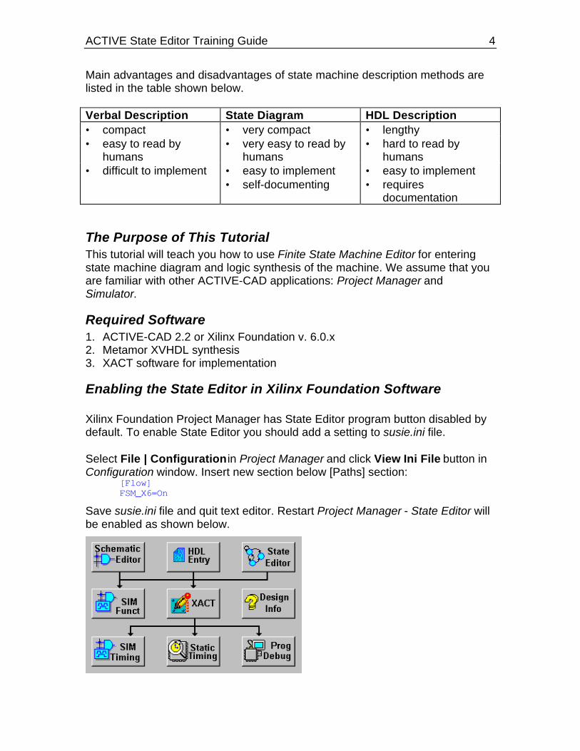
Main advantages and disadvantages of state machine description methods arelisted in the table shown below.
Verbal Description State Diagram HDL Description• compact • very compact • lengthy• easy to read by
humans• very easy to read by
humans• hard to read by
humans• difficult to implement • easy to implement • easy to implement
• self-documenting • requiresdocumentation
The Purpose of This TutorialThis tutorial will teach you how to use Finite State Machine Editor for enteringstate machine diagram and logic synthesis of the machine. We assume that youare familiar with other ACTIVE-CAD applications: Project Manager andSimulator.
Required Software1. ACTIVE-CAD 2.2 or Xilinx Foundation v. 6.0.x2. Metamor XVHDL synthesis3. XACT software for implementation
Enabling the State Editor in Xilinx Foundation Software
Xilinx Foundation Project Manager has State Editor program button disabled bydefault. To enable State Editor you should add a setting to susie.ini file.
Select File | Configuration in Project Manager and click View Ini File button inConfiguration window. Insert new section below [Paths] section:
[Flow]FSM_X6=On
Save susie.ini file and quit text editor. Restart Project Manager - State Editor willbe enabled as shown below.

ACTIVE State Editor Training Guide 5
Creating a State DiagramThe design which will be created in this tutorial is a machine which plays theBlackjack game. The Xilinx 4003 device is used to target the design.The following is the description of how the design should behave:
The purpose of the game is to request a desired number of cards byshowing the SAY_CARD output signal 1 and not exceed the total sum ofcards more than 21. Each card can be a number between 2 and 11,where 11 is called ACE and can be counted as 1 if desired. The arrival ofthe card is flagged on the signal NEW_CARD changing from 0 to 1.
The machine should request additional cards when the total sum of cardsis less then 17 and should flag a SAY_BUST signal when it exceeds 21.In case the total score is between 17 and 21 the machine should flag aSAY_HOLD signal.
The total score should be shown on the TOTAL output. After reachingSAY_HOLD or SAY_BUST the machine should stay in that state untilNEW_GAME signal is flagged on the input.
The NEW_GAME signal resets the machine.
ImplementationThe machine will be implemented by drawing a state diagram and thengenerating VHDL code, synthesizing into Xilinx netlist and then implementingusing XACT software.
1. Creating New BLKJACK Design• Start Foundation Project Manager• Create new project - select File | New Project and enter BLKJACK as the
project name in New Project window
ACTIVE State Editor Training Guide 6
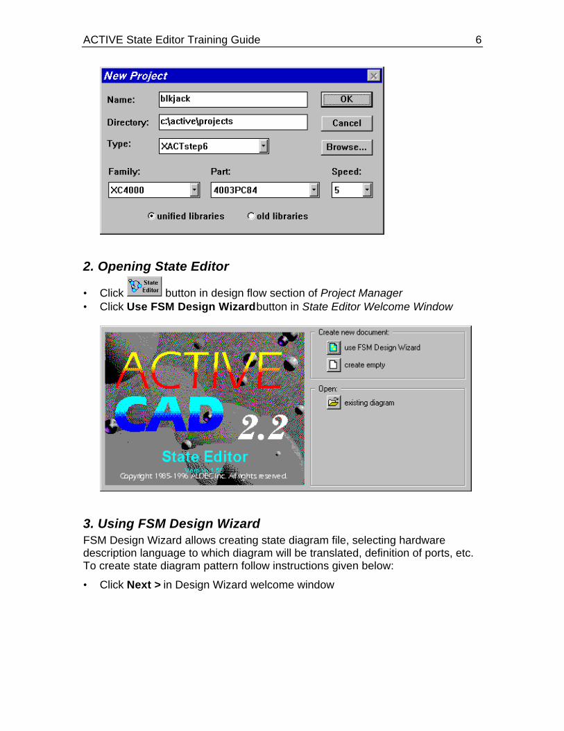
2. Opening State Editor
• Click button in design flow section of Project Manager• Click Use FSM Design Wizard button in State Editor Welcome Window
3. Using FSM Design WizardFSM Design Wizard allows creating state diagram file, selecting hardwaredescription language to which diagram will be translated, definition of ports, etc.To create state diagram pattern follow instructions given below:
• Click Next > in Design Wizard welcome window

ACTIVE State Editor Training Guide 7
• Select VHDL language in Design Wizard - Language window and click Next >button
• Type BLKJACK as the file name in Design Wizard - Name window and clickNext > button. Note that the default file extension of state diagrams is ASF. Inthis case the file will be called BLKJACK.ASF.

ACTIVE State Editor Training Guide 8
• Design Wizard - Ports window is displayed. It is used to add input and outputsignals used in your state machine.
To add new port in that window:- click New- type port name in Name: box- choose port direction by selecting one of the options in Direction box.Port names are displayed in the box above New button and in the symbolpreview area.

ACTIVE State Editor Training Guide 9
• Using procedure described above define:
◊ input ports: NEW_GAME NEW_CARD CARD[3:0]
◊ output ports: SAY_CARD SAY_HOLD SAY_BUST
• Click Next > when all ports listed above are defined. See picture below for
reference.

ACTIVE State Editor Training Guide 10
NOTE: The Advanced button displays Advanced Port Settings window belowand allows to specify the type of port.
You can define a selected signal as clock, and for the output port you canspecify if they are combinatorial or registered. Registered ports hold thevalue set in an additional register and the combinatorial outputs change anytime the input conditions change.
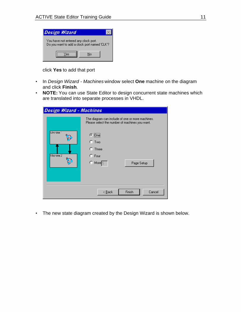
NOTE: State Editor support only synchronous state machines, which meansthat all transitions from one state to another are performed only at the clocktransitions. Since no clock was defined the Wizard will prompt you forcreating a clock signal.
• Design Wizard suggests adding CLK port -
ACTIVE State Editor Training Guide 11
click Yes to add that port • In Design Wizard - Machines window select One machine on the diagram
and click Finish.• NOTE: You can use State Editor to design concurrent state machines which
are translated into separate processes in VHDL.
• The new state diagram created by the Design Wizard is shown below.

ACTIVE State Editor Training Guide 12
4. Adding Extra PortsIn case you did not add some ports in the FSM Wizard you can do it afterwardsusing the Add port button. In this case the output port showing the total score ofthe game was not added.
• Click (Output Port) button, then click above the SAY_BUST portsymbol to add new output port.
• Click right mouse button on the port symbol you have just placed on thediagram and select Properties from the local menu
• In Port Properties window type TOTAL in Name: box, select 4:0 inRange: box, select Output and Registered options
• Click OK

ACTIVE State Editor Training Guide 13
NOTE: The TOTAL port has to have range from 0 to 31 which requires5 bits of data [4:0]
New output ports definition section should look the following:
5. Defining Additional VariablesIn our machine there will be a need to know if one of the cards is an ACE. Thiswill be helpful to count ACE as 1 instead of 11 in case the score exceeds 21.The following procedure describes how to define a new Ace variable.
• Double click //machine DECLARATIONS text below Sreg0 text

ACTIVE State Editor Training Guide 14
NOTE: If, for some reason, //machine DECLARATIONS text is missing, you
can still add machine declarations by clicking (Declarations) button • In the edit box
typevariable Ace: boolean;
below //machine DECLARATIONS text• Click right mouse button outside edit box.
Correct declarations should look the following:

ACTIVE State Editor Training Guide 15
6. Adding a Reset StateThe first state that will be added will be used to initialize the machine when thenew game is started. It will be used to set initial values of all outputs.
• Click button and place state symbol in the middle of the sheet, belowmachine declarations (use left mouse button to place state, right mousebutton to cancel state mode)
• Double click S1 state name to open edit box
and replace S1 by Start, then click outside the edit box. The state with newname should look like this:
• Select FSM | Machines | Sreg0 from the menu to display MachineProperties window. This window is used to define global settings of theselected state machine.

ACTIVE State Editor Training Guide 16
• Replace Sreg0 with Action in the Name: box. This sets the name of the statemachine signal used to store the current state in VHDL.
• Click on the Reset tab and select NEW_GAME as the reset signal name,Start as the reset state, synchronous reset type, and high active level. Thisdefines that the NEW_GAME will be used as machine reset and when it isactivated the machine will enter the Start state.

ACTIVE State Editor Training Guide 17
Click OK button - state diagram should look as below:
NOTE: The reset transition defines a reset condition fordocumentation purposes. The reset symbol is not a state and it indicatesthat this transition will be executed regardless of the current state if thecondition is met.
7. Adding initialization actionsOnce the reset condition is met the machine will enter the Start state. To definethe actions that should be performed when this happens we will create an entryaction. The entry action is always attached to the top of the state symbol andindicated that the code specified is executed once when the machine enters thisstate.
• Click (Entry Action) button, then position ‘dot end’ of the mouse pointerover Start state and click left mouse button. Type:
Ace := false;TOTAL <= "00000";SAY_CARD <= '0';SAY_HOLD <= '0';SAY_BUST <= '0';
in the edit box and click right mouse button outside edit box. Note that you have to use the VHDL syntax and add semicolons after each
line. Also note that the assignment operator <= can be used with ports andsignals, and the := operator is used with variables.
Defined entry actions are shown below:

ACTIVE State Editor Training Guide 18
NOTE: Combinatorial output port assignments in the reset state are also used as
default values in other states. This means that the output will be set to thedefault value in all states where the value was not explicitly indicated. In thisexample SAY_BUST will be ‘0’ in all states unless you add an actionSAY_BUST <= ‘1’.
8. Adding a state to request a cardOnce the reset is performed that machine should start with requesting a card.This will be the Hit_me state. • Add Hit_me state below Start state (use procedure described above for Start
state)
• Click (Transition) button, click Start state, click Hit_me state, then clickright mouse button.
NOTE: Unconditional transition from Start state to Hit_me state has been
ACTIVE State Editor Training Guide 19
defined. This transition is executed in the next clock cycle after entering theStart state (it means that the reset state will last for one clock cycle).
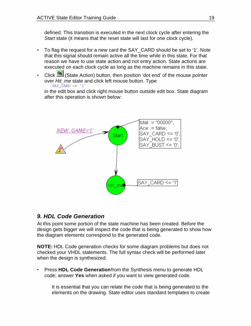
• To flag the request for a new card the SAY_CARD should be set to ‘1’. Notethat this signal should remain active all the time while in this state. For thatreason we have to use state action and not entry action. State actions areexecuted on each clock cycle as long as the machine remains in this state.
• Click (State Action) button, then position ‘dot end’ of the mouse pointerover Hit_me state and click left mouse button. Type
SAY_CARD <= '1' in the edit box and click right mouse button outside edit box. State diagram
after this operation is shown below:
9. HDL Code GenerationAt this point some portion of the state machine has been created. Before thedesign gets bigger we will inspect the code that is being generated to show howthe diagram elements correspond to the generated code.
NOTE: HDL Code generation checks for some diagram problems but does notchecked your VHDL statements. The full syntax check will be performed laterwhen the design is synthesized.
• Press HDL Code Generation from the Synthesis menu to generate HDLcode; answer Yes when asked if you want to view generated code.
It is essential that you can relate the code that is being generated to theelements on the drawing. State editor uses standard templates to create

ACTIVE State Editor Training Guide 20
the VHDL design and understanding the structure of the VHDL is veryhelpful when debugging the design when you use a VHDL simulator.
VHDL code generated by the State Editor can be divided into severalsections. Library section is always added at the beginning and provides theaccess to IEEE, METAMOR and SYNOPSYS libraries.
library IEEE;use IEEE.std_logic_1164.all;
-- SYNOPSYS library declarationlibrary SYNOPSYS;use SYNOPSYS.std_logic_arith.all;use SYNOPSYS.std_logic_unsigned.all;
library METAMOR;use METAMOR.ATTRIBUTES.all;
Entity declaration section lists all ports defined on the state diagram.entity blkjack is port (CARD: in STD_LOGIC_VECTOR (3 downto 0); CLK: in STD_LOGIC; NEW_CARD: in STD_LOGIC; NEW_GAME: in STD_LOGIC; TOTAL: out STD_LOGIC_VECTOR(4 downto 0); SAY_BUST: out STD_LOGIC; SAY_CARD: out STD_LOGIC; SAY_HOLD: out STD_LOGIC);end;
Global declarations section defines:◊ enumerated type and state variable of this type for every machine on your
diagram.◊ objects and actions common to all machines.
architecture blkjack_arch of blkjack is
--auxilary diagram declarations--diagram DECLARATIONS;
-- SYMBOLIC ENCODED state machine: Actiontype Action_type is ( Hit_me, Start);signal Action: Action_type;
begin--concurrent signal assignement--diagram ACTIONS;
Machine declarations section defines objects local to each machine(process).
process (CLK)--auxilary machine declarations--machine DECLARATIONSvariable Ace: boolean;

ACTIVE State Editor Training Guide 21
Reset definition sectionbegin
if CLK'event and CLK = '1' thenif NEW_GAME = '1' then
Action <= Start;TOTAL <= "00000";Ace := false;
Machine action description sectionelsecase Action is
when Hit_me =>when Start =>
Action <= Hit_me;when o thers =>
null;end case;end if;
end if;end process;
Output port assignment section-- signal assignment statements for combinatorial outputsSAY_CARD <= '1' when (Action = Hit_me) else '0';
SAY_HOLD <= '0';
SAY_BUST <= '0';
end blkjack_arch;
10. Receiving and Handling of the New CardOnce the new card is requested the machine should wait until it is received. Thearrival of the new card will be marked by the NEW_CARD signal. The followingwill add a next portion which performs this action.
• Add new state below Hit_me state• Rename this new state to Got_it using State Properties:
◊ click right mouse button inside state bubble, but not the state name◊ select Properties in the local menu◊ type Got_it in Name: box

ACTIVE State Editor Training Guide 22
◊ click OK• Add transition from Hit_me to Got_it state• Add condition to the recently drawn transition:
◊ click (Condition) button◊ click the transition line◊ type NEW_CARD='1' in the edit box◊ click right mouse button outside edit box
NOTES:⇒ state machine remains in Hit_me state until NEW_CARD=’1’ condition is
met⇒ SAY_CARD output returns to the default ‘0’ value when the machine exits
Hit_me state. This is because the default value ‘0’ was defined in the resetstate.
⇒ all actions are performed on rising edge of the CLK signal. This is alsodefined in Machine properties and can be changed if desired.
• Once the card was received, the total score needs to be updated. Also the
card will be checked if it was 11 and if so the ACE flag will be set.• Since these action need to be executed only once when entering the state an
entry action will be used. • To assign entry actions to the state, you can also use Actions card in State
Properties window:◊ click right mouse button inside state bubble◊ select Properties in the local menu◊ click Actions tab◊ type
TOTAL<=TOTAL+CARD;Ace:=(CARD=11) or Ace;
in Entry box
ACTIVE State Editor Training Guide 23
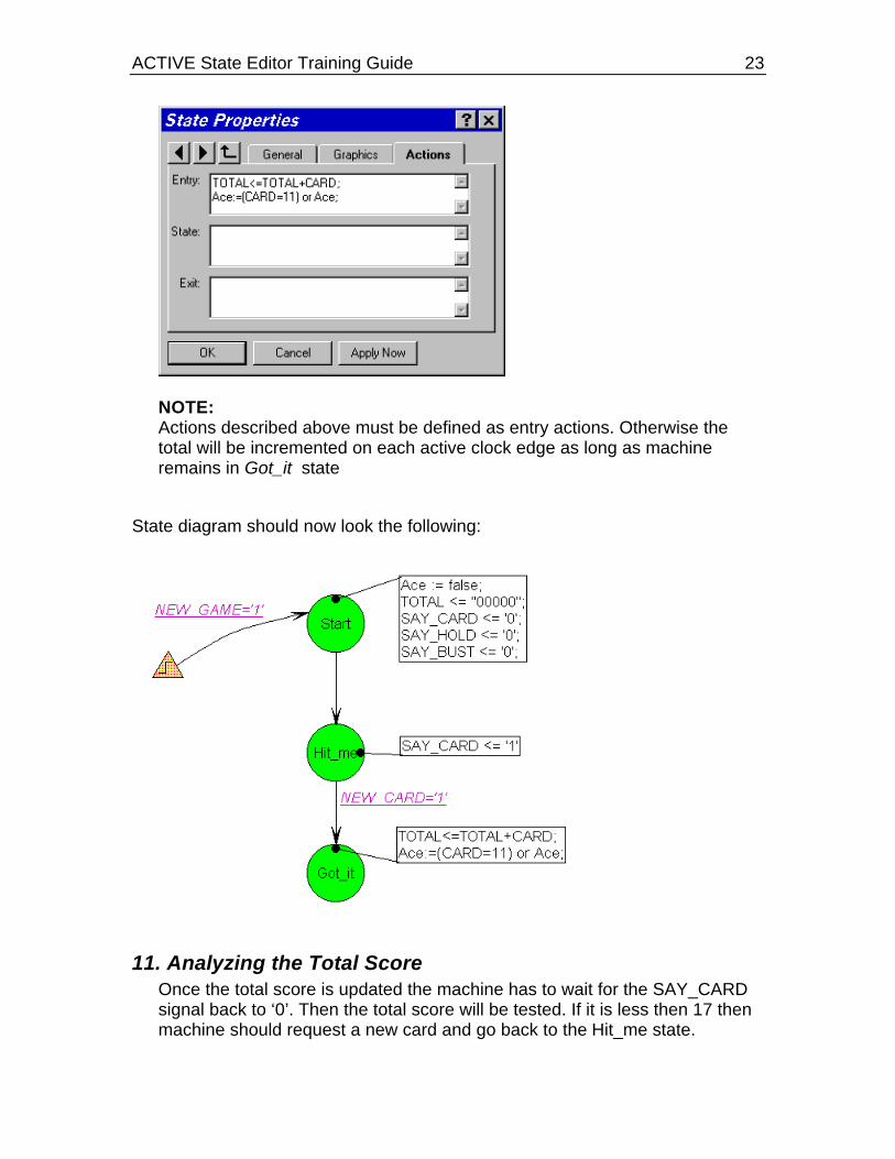
NOTE:Actions described above must be defined as entry actions. Otherwise thetotal will be incremented on each active clock edge as long as machineremains in Got_it state
State diagram should now look the following:
11. Analyzing the Total ScoreOnce the total score is updated the machine has to wait for the SAY_CARDsignal back to ‘0’. Then the total score will be tested. If it is less then 17 thenmachine should request a new card and go back to the Hit_me state.
ACTIVE State Editor Training Guide 24
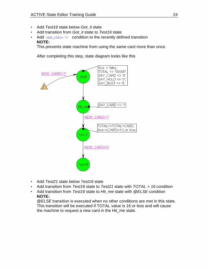
• Add Test16 state below Got_it state• Add transition from Got_it state to Test16 state• Add NEW_CARD=’0’ condition to the recently defined transition
NOTE:This prevents state machine from using the same card more than once.
After completing this step, state diagram looks like this
• Add Test21 state below Test16 state• Add transition from Test16 state to Test21 state with TOTAL > 16 condition• Add transition from Test16 state to Hit_me state with @ELSE condition
NOTE:@ELSE transition is executed when no other conditions are met in this state.This transition will be executed if TOTAL value is 16 or less and will causethe machine to request a new card in the Hit_me state.

ACTIVE State Editor Training Guide 25
State diagram with 5 states should look the following:
12. Testing the Final ScoreOnce the machine gets to the Test 21 state the total score is 17 or more. Nowthe machine has to test if it did not exceed 21. If it did not it will flag theSAY_HOLD signal if it has more than 21 the SAY_BUST signal should beflagged and the machine has lost the game. Before flagging the SAY_BUSTsignal the machine can check if one of the previous cards was an ACE and thenit may decrement the total value by 10 to recover from the bust situation.
• Add two final states: Bust and Hold.

ACTIVE State Editor Training Guide 26
• Add transition from Test21 state to Bust state and from Test21 state to Holdstate
• Add TOTAL < 22 condition to the Test21 ⇒ Hold transition• Add SAY_HOLD <=’1’ state action to Hold state• Add transition from Test21 state to Test16 state with Ace condition
NOTE:Since Ace is Boolean variable, no relational operators are required in thecondition text
• Add TOTAL <= TOTAL-10 action to the recently defined transition (use button, click transition line and type action text)NOTE:Transition actions allow avoiding redundant states. If you did not assign thisaction to a transition than another state would be created to execute TOTAL<= TOTAL-10 action.
• Add @ELSE condition to the Test21 ⇒ Bust transition• Add SAY_BUST <=’1’ state action to Bust state
State diagram with all states, transitions, conditions, and actions should looklike this
13. Assigning Condition Priorities• NOTE that in Test21 state both TOTAL < 22 and Ace conditions can be met
at the same time. In that case behavior of the machine depends on condition

ACTIVE State Editor Training Guide 27
evaluation sequence. To avoid confusion, you should assign differentpriorities to transitions. Because our machine should first check if TOTAL isless than 22, assign priority 1 to Test21 ⇒ Hold transition and priority 2 toTest21 ⇒ Test16 transition.
To change transition priority:◊ click transition line◊ click right mouse button◊ select Priority from the local menu◊ select required priority level
NOTE:Transitions without displayed priority are executed last
14. Selecting State EncodingWhen state machines are compiled into logic the current state is stored in aregister (series of flip-flops). The values each state is assigned in the registermay have an effect in the reliable behavior of the state machine. Incorrectselection of state encoding can create hazard conditions where a glitch in thecombinatorial logic may cause the state machine to enter a wrong state. Therecommended encoding type for all FPGAs is One-Hot which assigns values toeach state so that only one bit of a register is active ant any time. One hotencoding, however, consumes more flip flops because each state requires a bitin a register and for that reason is not recommended for CPLDs which lack flipflop resources. State Editor supports one-hot and binary encoding. Other typesof encoding can be created by manually assigning the codes to each state.
In this tutorial a binary encoding will be used for simplicity of analysis in thesimulator.

ACTIVE State Editor Training Guide 28
• Select FSM | Machines | Action and select binary encoding in MachineProperties window
NOTE:Symbolic encoding option allows synthesis tool to select state encodingmethod. Metamor XVHDL defaults to binary encoding if the codes are notassigned any values.
• Select Tools | Preferences and check Display State Codes option
• Save the diagram
15. Compiling the Design• Save the diagram• Select Project | Add to project in State Editor Menu to add BLKJACK.ASF
diagram as top-level document in your project. This will add the top level
document in Project Manager hierarchy navigator.

ACTIVE State Editor Training Guide 29
• Select Synthesis | Options
and deselect X-BLOX and Improvex options to speed up the synthesisprocess.
• Select Synthesis | Synthesize option (or click button)
16. Locating and Correcting Errors• Note that Signal 'TOTAL' is not readable as it has mode OUT.
error is reported every time TOTAL appears on the right side of signalassignment. This is because the output ports cannot be used for reading.Instead the bidirectional port should be used.
• To correct this error, click right mouse button on TOTAL port symbol, selectProperties and change port type to Bidirectional
• Restart synthesis - this time it should complete without errors• Note that state codes appeared inside state bubbles• Select Synthesis | View Report and check how many flip-flops were used
for synthesis.
NOTE: If Improvex is used during synthesis, synthesis report also includesmapping information.
Synthesis report is very important, because it shows how much resources areused by the design. Making some changes on the diagram may drasticallyincrease or decrease the number of flip-flops and CLBs.
17. Functional Simulation• Minimize State Editor
• Click button in Project Manager design flow section

ACTIVE State Editor Training Guide 30
• Select Signal | Add Signal and double-click on CLK, NEW_GAME,NEW_CARD, (CARD0,CARD3), (TOTAL0,TOTAL4), SAY_BUST,SAY_CARD, SAY_HOLD, and (ACTION2,ACTION0) signals to select themfor observation in Waveform Viewer
NOTE: ACTION bus represents the state variable of Action machine. Itenables monitoring of the current machine state.
• Selected signals should look like on the picture below
NOTE: To ensure correct display of bus values, check if ‘∗’ (asterisk) isdisplayed by the bus element with index 0. In asterisk is not displayed there,select all bus members by clicking their names while holding Shift key andselect Signal | Bus | Direction
• Select Utilities | View | Hex Buses• Select Stimulator | Add Stimulators and assign B0 stimulator to CLK input

ACTIVE State Editor Training Guide 31
• Click Formula button in Stimulator Selection window and define F0, F1, andF2 stimulators:
◊ Assign (H20L580)10 formula to F0 stimulator◊ Assign (L80H20)10 formula to F1 stimulator◊ Assign [0]100[a]100[3]100[8]100 formula to F2 stimulator◊ Click Close
• Attach F0 stimulator to NEW_GAME input, F1 stimulator to NEW_CARDinput, and F2 stimulator to CARD input bus
• While holding Shift key select CARD and TOTAL buses• Select Signal | Bus | Display Decimal.
Signal names in Waveform Viewer should look like on the picture below
• Simulate using Step or Long button until machine signals SAY_HOLD orSAY_BUST.NOTE:Remember that ACTION bus value is equal to current state code.You can change sequence of cards by editing F2 stimulator formula.
ACTIVE State Editor Training Guide 32
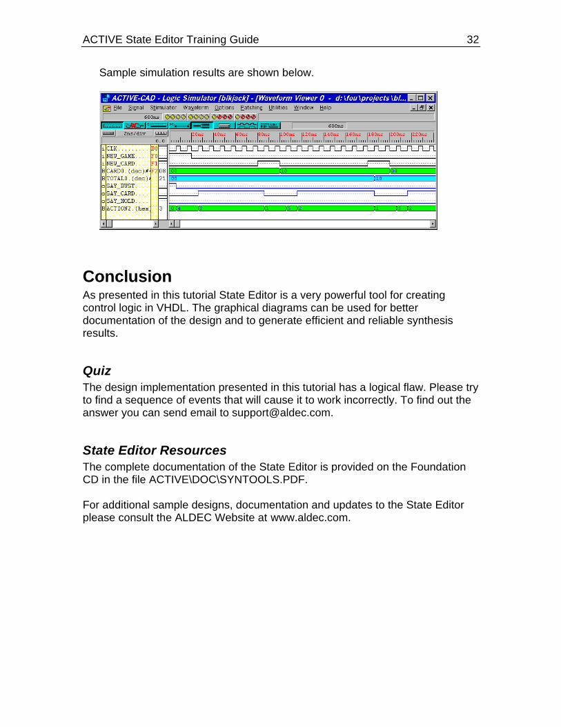
Sample simulation results are shown below.
ConclusionAs presented in this tutorial State Editor is a very powerful tool for creatingcontrol logic in VHDL. The graphical diagrams can be used for betterdocumentation of the design and to generate efficient and reliable synthesisresults.
QuizThe design implementation presented in this tutorial has a logical flaw. Please tryto find a sequence of events that will cause it to work incorrectly. To find out theanswer you can send email to [email protected].
State Editor ResourcesThe complete documentation of the State Editor is provided on the FoundationCD in the file ACTIVE\DOC\SYNTOOLS.PDF.
For additional sample designs, documentation and updates to the State Editorplease consult the ALDEC Website at www.aldec.com.