Download
10
-
Upload
angelus256 -
Category
Documents
-
view
9 -
download
4
Transcript of Download

Rapid CFD Simulation ofInternal Combustion EnginesH. Jasak�, J.Y. Luo, B. Kaluder�ci�c and A.D. GosmanComputational Dynamics Ltd.H. Echtle, Z. Liang and F. WirbeleitDaimler-Benz AGM. WierseSGI/Cray ResearchS. Rips and A. WernerUniversity of StuttgartG. Fernstr�om and A.KarlssonAB Volvo Technological DevelopmentABSTRACTMulti-dimensional modelling of the ow and combustionpromises to become a useful optimisation tool for ICengine design. Currently, the total simulation time foran engine cycle is measured in weeks to months, thuspreventing the routine use of CFD in the design process.Here, we shall describe three tools aimed at reducing thesimulation time to less than a week. The rapid template-based mesher produces the computational mesh within1-2 days. The parallel ow solver STAR-CD performsthe ow simulation on a similar time-scale. The packageis completed with COVISEMP , a parallel post-processorwhich allows real-time interaction with the data.INTRODUCTIONCurrently, the design of Internal Combustion (IC) en-gines relies mainly on experimental methods, where en-gine prototypes are constructed and tested in a rangeof operating regimes. A substantial amount of accumu-lated knowledge allows the engineer to meet the strin-gent demands on performance, emissions and fuel econ-omy. However, as the complexity of the engine and thenumber of criteria that need to be achieved simultane-ously increases, it becomes more and more importantto understand and control the details of the ow, sprayand the combustion processes. In the search for moredetailed information about these in IC engines, Com-putational Fluid Dynamics (CFD) potentially o�ers an�Corresponding author, Computational Dynamics Ltd,Olympic House, 317 Latimer Road, London W10 6RA, England,Tel: (+44) 181 969 9639, Fax: (+44) 181 968 8606
insight that can be reached experimentally only withgreat di�culty.In some other areas of engineering design, CFD isalready complementing experiments as a standard di-agnostic tool in the optimisation process. Typical ex-amples of this kind are the coolant jackets of IC en-gines, under-hood ows and passenger compartmentsin the automotive industry, air-conditioning systems forbuildings, cooling of electronic components etc. Theaerospace industry has replaced a lot of its prototypetesting with CFD simulations.In the simulation of the ow and combustion in ICengines, the progress seems to be slower. Here, CFD isused primarily as a research tool, for a number of rea-sons. The �rst is the physical complexity of the owmodels. The system of partial di�erential equations tobe solved consists of the Reynolds-averaged compress-ible Navier-Stokes equations with the constitutive rela-tions for an ideal gas mixture, the energy equation, aturbulence Reynolds stress- ux model, spray model, ig-nition, chemical reaction and combustion model. Addi-tionally, the ow is unsteady and some boundaries (pis-ton and valves) move in time.Progress in combustion (and turbulence) theory [1]has provided a number of models that claim good ac-curacy and predictive properties, thus setting the basefor further use of CFD in engine design. However, thehigh cost of the computation and the complexity of thesetup still hinder the routine use of CFD in the designprocess. For example, a typical turn-around time forthe simulation of an IC engine can be of the order ofmany weeks. This is caused by several factors describedbelow.1

From the point of view of mesh generation, an ICengine is a complex geometry. The complexity is fur-ther increased by the moving boundaries: after the meshhas been built, it is necessary to prescribe its movementin time to accommodate the movement of the bound-aries. Moreover, for good accuracy it is also advisableto modify the topology of the mesh to preserve the sen-sible aspect ratios of the cells which changes with theboundary movement. For example, a mesh consisting ofcubes at BDC may be unacceptably deformed at TDC.Therefore, the number of cell layers between the cylin-der head and the piston needs to be changed as thepiston moves. A similar action is also necessary aroundthe valves as they open and close. In addition, the meshquality should be preserved throughout the whole calcu-lation. This sometimes requires additional connectivitychanges: an acceptable mesh with the valves closed maybecome highly distorted when the valves open. Addi-tional complexity is introduced if the volumes swept bythe valves overlap with each other and with the volumeswept by the piston, a situation regularly encounteredin pent-roof designs.A sensible number of cells for combustion calcu-lations in IC engines typically consists of around sixtythousand cells at TDC, rising to about three times asmany at BDC. Additional mesh is needed to model theinlet and exhaust manifolds, giving the typical totalmesh size of around 300 000 cells. A typical integrationtime-step is usually around 0:1 of a degree Crank-Angle(CA). Allowing for some run-in time, a single enginecycle (720o CA) would thus easily require 10 000 time-steps. The simulation time for such a setup has been re-ported to be around 2 months on a fast single-processorworkstation [2]. Currently, Daimler-Benz routinely runssimulations on meshes with similar resolution over 500oCA, with 4 000 time-steps in 3 weeks.The amount of data available from the calculationsdescribed above is extremely large. Potentially, it canprovide the spatial distribution of any of the variables(�, U, p, T , k, �, species concentration and combustionvariables) for all time-steps, but usually only selecteddata is of interest. Even the reduced set of data may beso large that it becomes very di�cult to analyse. Ideally,one would like to visualise the iso-surfaces of di�erentvariables, plot cutting lines or planes mapped with thescalar or vector data and follow the tracks of seeded par-ticles. Also, to aid understanding of the details of the ow, it would be useful to be able to generate anima-tions of any of the above properties, with the possibilityof \live" interaction with the data. All of the above re-quires a very powerful computer, capable of storing vastamounts of data [3].Having in mind the complexity of the mesh genera-tion and mesh movement requirements, long simulationtimes and the complexity of the post-processing, a singlesimulation cycle from the CAD description to the dataanalysis using conventional methodology could take up
to two months. Moreover, even relatively small changesto the setup are often neither easy nor quick, as theymight require a review of the whole of the mesh move-ment and/or the mesh structure.In a design cycle, an engineer would typically like toexamine tens of di�erent load regimes and engine speeds,for several con�gurations of, say, inlet manifolds, valvetimings, valve shapes etc. This is clearly not feasiblewithin the current turn-around time. If the results of aparametric study are to be used to improve the design,they need to be available in the time-frame of severaldays and even less for simple modi�cations, like a changein the valve lift pro�le or inlet port shape. This paperdescribes the main elements of a project that had as itsmajor objective the reduction of the simulation time tomeet these requirements.RAPID SIMULATIONSTRATEGYThe HPS-ICE project was set up with the goal of re-ducing the turn-around time for the complete simula-tion cycle of an IC engine to 1 week or less. In order toachieve this, improvements were made to every step ofthe simulation cycle by adapting the following strategy:� In the �rst instance, it is necessary to consider-ably speed up the mesh generation and the setupof mesh movement, while preserving good quality.For this purpose, a template-based mesh genera-tor is developed, based on previous experience of\good" mesh generation practices and capable ofproducing parametrised mesh movement routines.The aim is to enable creation of a mesh and the as-sociated movement routines within 1-2 days, withthe possibility of easy and quick changes of key en-gine parameters (eg. valve shape, valve timings andthe lift curve, shape of piston head, details of thecombustion dome geometry, position of the fuel in-jector etc.).� The necessary reduction of the simulation time isachieved with the use of parallel computers. Scal-able speedups for the CFD codes on massively par-allel computers have been reported in the past [3,4]but not for the cases involving moving meshes andtopology changes. If a similar speedup could beachieved for IC engine simulations, the turn-aroundtime could be reduced to a few days or less, in linewith the target time-frame.� The parallelisation of the solver opens an interest-ing option for rapid post-processing. Most of thenecessary data analysis can be done on the dis-tributed data sets, using the computational powerof the parallel machine as a back-end for the graph-ics renderer. Once the data is processed, the actual2
visualisation can be done on a workstation withgood graphics performance. This would allow thesimultaneous use of the large memory and comput-ing power of the parallel platform, bringing closerthe goal of the \live" interaction with the data.In the rest of this paper, the successful develop-ment of the components outlined above will be describedin more detail. Example results of the application ofthe methodology for the cold ow and combustion sim-ulation to a representative 4-valve pent-roof engine willalso be presented, together with some parallel speedupresults and examples of post-processing. Finally, a sum-mary and indication for future work will be given.TEMPLATE-BASED MESHGENERATORA reliable automatic mesh generator for IC engine ap-plications is still a subject of research rather than indus-trial reality. Although the progress in recent years hasbeen signi�cant, the \ultimate" mesh generator whichproduces good quality (preferably hexahedral) meshesfor arbitrarily shaped domains with moving boundariesis still not available.Currently, the best meshes for IC engine geome-tries are created by skilled engineers with extensive ex-perience in this area. The approach taken here has beento automate the mesh generation process, based on theknow-how of experienced specialists and make it avail-able to the average user.Pro-ICE, the engine-speci�c mesh generator devel-oped within the HPS-ICE project is based on the prin-ciple of template-mapping. The process is divided intothe following stages:� The �rst stage is the analysis of the geometry inquestion, to establish the salient features. Theseinclude the type (Diesel or petrol), the number ofvalves, the type of the combustion dome (eg. at,basic pent-roof, shallow etc.), the geometry of themanifolds (separate, Siamese) etc. Other basic di-mensions and characteristics of the engine are alsospeci�ed: the piston diameter, the connecting rodlength, the stroke, the engine speed and the maxi-mum valve lift.� The second stage is the construction of the tem-plate, which is a mesh having the necessary topo-logical features but not at this stage conforming tothe actual geometry. The appropriate parts of thisare extracted from a \template" library and themesh for each part is described with a number ofparameters which de�ne the local mesh resolution.For example, the parameters de�ning a valve tem-plate are: no. of circumferential cells, no. of celllayers for the maximum lift, no. of ring radial cells
(bottom, inner and outer), length of the valve stemcylinder etc. When all the parameters are de�ned,the template mesh is created automatically. It isalso possible to subsequently modify the templatemanually in order to simplify the mapping process.� The next stage is to input the actual geometry ofthe engine. Usually, this information is available ina CAD format and is passed to the mesh genera-tor as a shell surface mesh for the combustion domeand the arms, along with a set of pro�les describingthe shape of the valves. The description of the ge-ometry is completed with the de�nition of the valvelift curves.� Finally, the template is mapped onto the real ge-ometry. This is done in several stages, the �rst ofwhich is the identi�cation of \feature edges" of thetemplate and the geometry. Once the edges and thecorresponding surfaces are matched, the rest of themesh is created by projection and mesh smoothingalgorithms. The �nal mesh, together with the as-sociated movement instructions automatically pro-duced by the mesh generator are written in a formatsuitable for the ow solver.The remaining preparations for the simulation are donein the pre-processor for the ow solver. This includesthe selection of the turbulence and combustion models,the type of fuel, the ignition timing, the time-step size,total simulation time etc. The code is now ready to run.THE TEMPLATE LIBRARY As alreadynoted, within the mesh generator there exists a library oftemplate geometries for di�erent engine con�gurations.This is the most technically demanding part of the meshgeneration: each template is based on the previous ex-perience about the \best" mesh structure for the geome-try in question. The templates are also interchangeable,making it easy to, for example, change the port type ona Diesel engine. Each of the templates also comes withthe associated parametrised mesh movement routines.Once the mesh is completed, the �nal mesh movementis automatically assembled from the segments from allparts of the mesh.Two example templates are shown in Fig. 1. The�rst, Fig. 1(a), shows a 2-valve Diesel engine with a atcombustion deck and a steep helical intake port. Theexhaust port is not included in this template. Fig. 1(b)shows the template for a 4-valve petrol engine withSiamese arms on both the intake and the exhaust side.The template library covers various con�gurationsof port and intake arm geometries and is continuouslybeing enlarged. It is also possible to manually modifythe template mesh before the mapping process. Pistonbowls, spark plug geometry and other similar featurescan be treated in this way, with the aid of the \ArbitraryInterface" mesh matching feature [5] of the ow solver.3

(a) 2-valve Diesel engine.
(b) 4-valve petrol engine.Figure 1: Template mesh.If an appropriate template is not available, the tem-plate mesher can be used to build only the moving partsof the mesh, which is then combined with a mesh for themanifolds built in some other way. Such an example isshown in Fig. 2. The �nal (mapped) mesh with the sep-arate mesh for the manifolds is shown in Fig. 3. Thetwo meshes are again interfaced using the \ArbitraryInterface" feature.THE MAPPING PROCESS The process ofmapping the features of the template to the real ge-ometry is done in three stages. Initially, the edges ofthe template are paired with the corresponding edgeson the shell surface. Once the pairing is established,the edge vertices of the template are mapped to thecorrect position on the shell surface. The surfaces ofthe template are then projected onto the new geometry.The remaining work consists of the trans�nite mappingof the internal mesh and a number of smoothing steps,both on the surface and the interior of the model. Thefeature edges of the geometry are preserved during thesmoothing process.
Figure 2: 4-valve Diesel engine template without the man-ifolds.
Figure 3: Complete mesh.Fig. 4 shows the intake port for the template andthe �nal mesh for the engine simulation example men-tioned earlier, which is the Daimler-Benz M-111 design.The template was manually modi�ed before the map-ping to accommodate the fuel injector cavity above theintake manifold, while the regularity and spacing of thetemplate is preserved in the �nal mesh.The mesh movement information is provided to the ow solver \on-the- y". When the actual mesh topologychanges, the mapping and smoothing will be repeated toobtain the new vertex positions. If no topology changeoccurs, the vertex positions are calculated using \smartinterpolation", which guarantees that the edges and sur-faces of the geometry will be preserved.Fig. 5 shows cross-sections through the mesh fortwo crank angles. In comparison with hand-builtmeshes, the template-based mesh is of higher qual-ity, having lower average warpage angle and non-orthogonality. Moreover, the quality of the mesh is pre-served during the mesh motion, which is not always thecase for the hand-built meshes.4

e1e
e3e
e4e
e5e
e6e
e7ee8ee9e
e10ee11ee12e
e13e
e15e
e16e
e17e
e19e
e20e
e25e
e26ee27e
e28e
e29e
e30e
e31e
e32e
e33e
e34e
e35e
e37e
e38e
e39e
e40e
e41e
e42e
e66e
e68e
e69e
e76e
e77e
(a) Template mesh.e1e
e3e
e4e
e5e
e6e
e7ee8ee9e
e10ee11ee12e
e13e
e15e
e16e
e17e
e19e
e20e
e22e
e25e
e26e
e27e
e28e
e29e
e30e
e31e
e32e
e33e
e34e
e35e
e37e
e38e
e39e
e40e
e41e
e42e
e66e
e68e
e69e
e76e
e77e
(b) Mapped mesh.Figure 4: Mesh template and �nal mapped mesh for theDaimler-Benz M-111 geometry.
C.A. = 390.0
C.A. = 540.0Figure 5: Mesh movement for the Daimler-Benz M-111geometry.SIMPLE MODIFICATIONS The template-based mesh generator described above allows quick mod-i�cations of the original mesh, both in terms of meshmovement and geometrical detail. For example, achange in the valve lift curve or in valve timing cannow be done simply on a \point-and-click" basis, as themesh movement routines are modi�ed automatically.Geometrical modi�cations can also be rapidly ac-commodated. Typically, the mesh structure and mostof the edge mapping stays the same and only minimaluser-interaction is needed.5

PROBLEM SETUP AND THESOLUTION ALGORITHMThe simulation of the fully premixed combusting ow inthe M-111 engine is done using the standard k�� modelwith wall functions to account for turbulence, with thecombustion modelled by the premixed version of the 2-equation Weller model [6{9]. Additionally, two \passivescalar" transport equations are solved to track the freshcharge and the residual gas, bringing the total numberof equations solved to 11. The engine operates at 1500rpm and at part load, with the intake manifold pressureof 0:45bar. The fuel-air mixture is stoichiometric withno residual gas recirculation and ignition occurs at 10oCA before TDC. The calculation starts 30o CA beforethe TDC and lasts for 750o CA, with the time-step sizecorresponding to 0:1o CA.PARALLEL FLOW SOLVER The owsolver used in this study is the parallel version of STAR-CD. The equations are discretised using the �nite vol-ume method and a segregated solution algorithm on amoving grid with topology changes [5].The parallelisation is done through domain decom-position, where a portion of the mesh is assigned toeach processor. The exchange of information on theinter-processor boundaries is performed in the message-passing paradigm, suitable both for shared and dis-tributed memory computers. The mesh decomposer andother parallel setup tools are a part of the pre-processingpackage for the ow solver. The parallel performance ofthe code on static meshes has been reported before, withthe linear scaling behaviour observed on up to 32 CPUsand beyond [4, 10].In an ideal parallel code the work should be equallydivided between the processors. For the FV solvers, thisis usually achieved by evenly distributing the cells andat the same time trying to minimise the communicationbetween the processors. If the mesh topology does notchange in time, this is done only once, at the beginningof the calculation. In engine simulations, due to thecell layer addition/removal, an initially well-balanceddecomposition may deteriorate and re-balancing mightbecome necessary: this could be done dynamically dur-ing the run, using one of the tools specially designedfor this purpose (eg. JOSTLE [11]). One should, how-ever, �nd an appropriate trade-o� between the cost ofthe load imbalance and the additional balancing work.Currently, we have adopted a strategy where themesh is initially decomposed in such a way that thecell activation/deactivation occurs evenly over all sub-domains, thus preserving to a certain degree the initialload balance. This is achieved by a pie-like decomposi-tion in the moving part of the mesh. While a solution ofthis kind is cost-e�ective on a relatively small numberof CPUs as it incurs no re-balancing cost, it might notbe appropriate for very large meshes and massive paral-
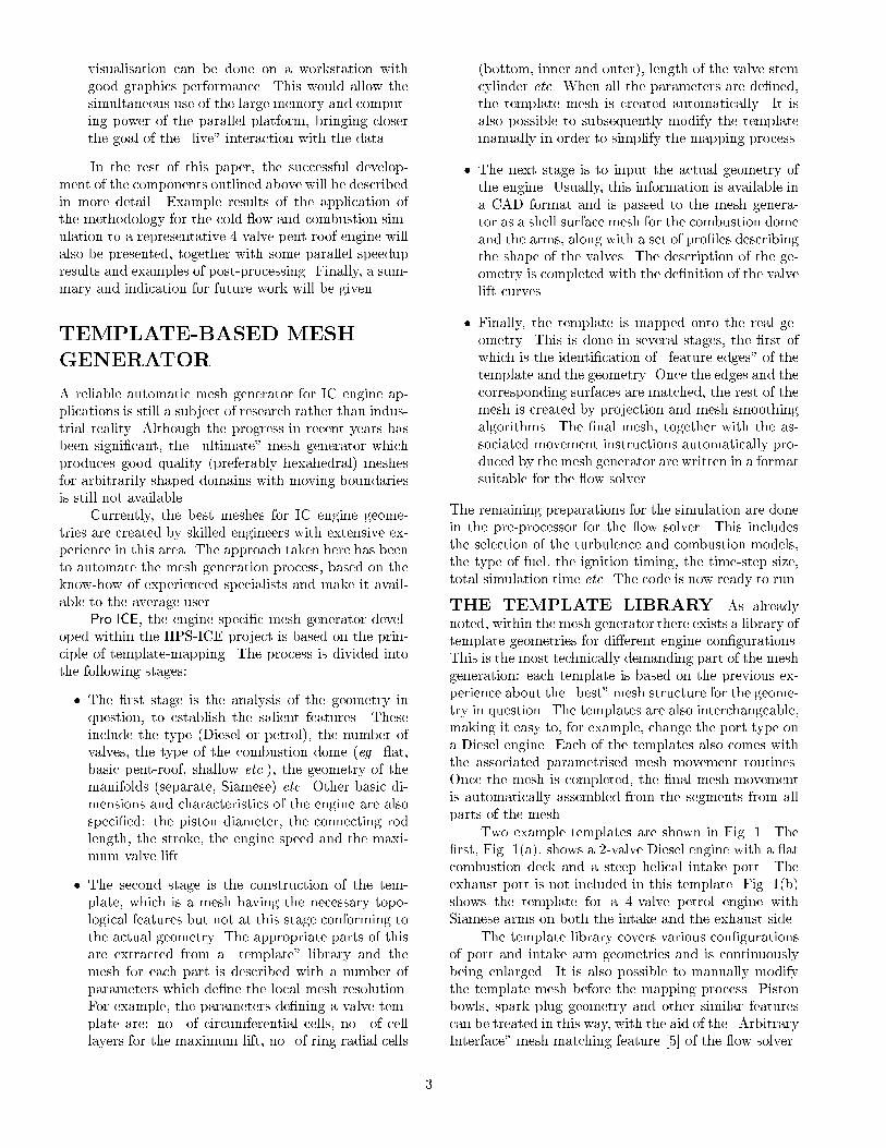
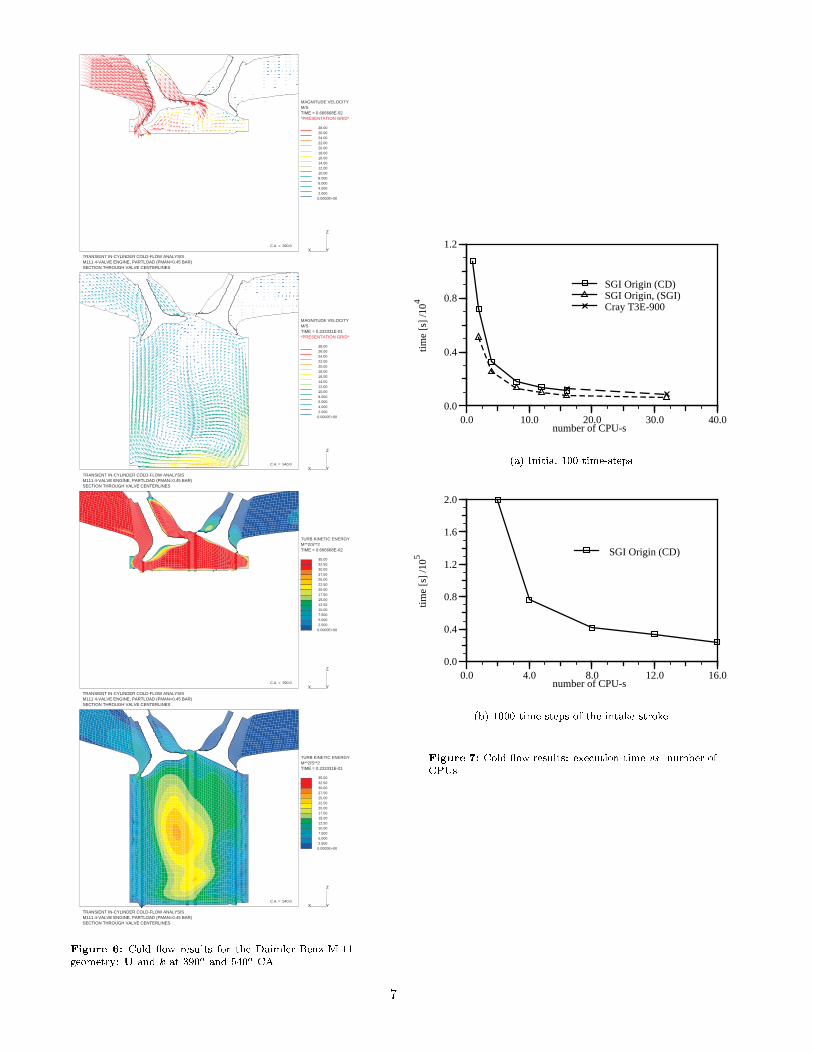
lelism. For that purpose we need to resort to dynamicload balancing and tests of this are already under way.The balanced domain decomposition for the Eu-lerian part of the calculation does not imply the bal-anced load related to the Lagrangian particle-trackingprocedure used in the spray model. Here, the pie-likedecomposition of the combustion deck may improve thesituation for multi-nozzle Diesel injectors, but a betterpractice is still under development.INDUCTION RESULTS The ow �elds fortwo di�erent piston positions are presented in Fig. 6.Fig. 7 shows the reduction in the execution timewith the number of CPUs on the parallel machine. Theresults are presented for three parallel computers: a 180MHz 24-CPU SGI Origin 2000 (CD), a 195 MHz 14-CPU SGI Origin 2000 (SGI) and a 512-CPU Cray T3E-900. The initial test was performed for the �rst 100time-steps and then repeated for 1000 time-steps of theintake stroke on one of the machines.In all three cases the elapsed time per time-stepon 16 CPUs is around 20 s per time-step. This wouldequate to 144 000 s, or 40 hours for 720o CA, in linewith the target turn-around time. In terms of parallele�ciency the data in Fig. 7(b) corresponds to a speedupof 15.4 on 16 CPUs, only marginally worse than typicalresults for static mesh applications [10].COMBUSTION CALCULATIONS Thecombustion calculations for the M-111 case on the par-allel platforms are incomplete at the time of writing;the full parallel performance data have not yet been as-sembled. However the need for this capability can bedemonstrated now, by reference to Fig. 8. This showsmeasured and calculated ame propagation, the latteron two meshes with 150 000 and 300 000 cells, respec-tively. The results on the �ner mesh are clearly in closeragreement with the measurements, indicating that atleast this degree of resolution is required for accuracy.POST-PROCESSINGTechniques for analysing large amounts of data in ashort period of time is the �nal component of the rapidanalysis system. The aim is to provide post-processingtechniques appropriate for the data in question: line andplane cuts with the scalar and vector data mapped ontothem, iso-surfaces of the selected �eld, possibly colouredby some other �eld and particle traces. Further, the userwould be able to interactively modify the parameters forany of the above, spin and zoom in on parts of the ge-ometry and �nally perform an animation consisting ofat least 100 time-steps for the �eld in question.The post-processing issues described above need tobe seen in the light of the size of data sets in question.Sometimes it may be physically impossible to operateon the data to any other available computer apart from6
MAGNITUDE VELOCITY M/S TIME = 0.666668E-02 *PRESENTATION GRID*
28.00 26.00 24.00 22.00 20.00 18.00 16.00 14.00 12.00 10.00 8.000 6.000 4.000 2.000 0.0000E+00
X Y
Z
TRANSIENT IN-CYLINDER COLD-FLOW ANALYSISM111 4-VALVE ENGINE, PARTLOAD (PMAN=0.45 BAR)SECTION THROUGH VALVE CENTERLINES
C.A. = 390.0
MAGNITUDE VELOCITY M/S TIME = 0.233331E-01 *PRESENTATION GRID*
28.00 26.00 24.00 22.00 20.00 18.00 16.00 14.00 12.00 10.00 8.000 6.000 4.000 2.000 0.0000E+00
X Y
Z
TRANSIENT IN-CYLINDER COLD-FLOW ANALYSISM111 4-VALVE ENGINE, PARTLOAD (PMAN=0.45 BAR)SECTION THROUGH VALVE CENTERLINES
C.A. = 540.0
TURB KINETIC ENERGY M**2/S**2 TIME = 0.666668E-02
35.00 32.50 30.00 27.50 25.00 22.50 20.00 17.50 15.00 12.50 10.00 7.500 5.000 2.500 0.0000E+00
X Y
Z
TRANSIENT IN-CYLINDER COLD-FLOW ANALYSISM111 4-VALVE ENGINE, PARTLOAD (PMAN=0.45 BAR)SECTION THROUGH VALVE CENTERLINES
C.A. = 390.0
TURB KINETIC ENERGY M**2/S**2 TIME = 0.233331E-01
35.00 32.50 30.00 27.50 25.00 22.50 20.00 17.50 15.00 12.50 10.00 7.500 5.000 2.500 0.0000E+00
X Y
Z
TRANSIENT IN-CYLINDER COLD-FLOW ANALYSISM111 4-VALVE ENGINE, PARTLOAD (PMAN=0.45 BAR)SECTION THROUGH VALVE CENTERLINES
C.A. = 540.0Figure 6: Cold ow results for the Daimler-Benz M-111geometry: U and k at 390o and 540o CA.
0.0 10.0 20.0 30.0 40.00.0
0.4
0.8
1.2
number of CPU-stim
e [s
] /1
04
SGI Origin (CD)SGI Origin, (SGI)Cray T3E-900
(a) Initial 100 time-steps.
0.0 4.0 8.0 12.0 16.00.0
0.4
0.8
1.2
1.6
2.0
number of CPU-s
time
[s]
/105 SGI Origin (CD)
(b) 1000 time-steps of the intake stroke.Figure 7: Cold ow results: execution time vs. number ofCPUs.
7

Figure 8: Experimental comparison of the ame propaga-tion.the parallel supercomputer used for the ow simulationbecause of the memory requirements. Although paral-lel computers o�er a huge increase in performance, theyare designed as batch machines and their graphics per-formance is often poor. On the other hand, a high-end workstation provides fast (hardware-accelerated)graphics and supports some interesting special post-processing devices, like stereo-vision or virtual reality.The optimal approach to the post-processing require-ments would therefore be to use the high computingpower (and storage) of a supercomputer in combinationwith the high graphics performance of a workstation.COVISEMP [3, 12, 13], the distributed visualisationsoftware environment, allows direct operation on thedata sets created by the parallel ow solver. Fortu-nately, most of the algorithms used to perform the post-processing operations described above can be done ona cell-by-cell basis with no inter-processor dependenceand therefore parallelise naturally (the notable excep-tion is the particle-tracking). Once the visualisationdata is assembled, it is passed to the rendering partof the package, which operates on a workstation. Ac-celerated graphics hardware allows interaction with therenderer in real time. If any of the post-processing pa-rameters (like the iso-surface level) changes, the back-end supercomputer is again brought into action.Fig. 9 shows the post-processing environment, con-sisting of the Process Control Panel, which de�nes the ow of data, several menus, allowing the user to specifythe post-processing parameters and the rendered win-dow. The last-named shows the ame front and thetemperature mapped onto a semi-transparent cuttingplane.
Figure 9: COVISEMP post-processing environment.The above approach allows post-processing of thedata sets in question with almost live interaction. Al-though the \chain" of post-processing has been bro-ken in a sensible place, the communication between theback-end supercomputer and the renderer on the work-station is still intensive. The limiting factor in the wholeprocess, nonetheless, is the band-width of the connec-tion between the two.Having in mind the limited capacity of this datalink between the back-end and the workstation, one wayof enhancing the performance of the post-processor isthe use of data reduction techniques. Also, data re-duction will result in faster rendering and interactionwith the data and reduced memory requirements on theworkstation, which is particularly useful in animations.The data reduction approach used here relies on thefact that the computational mesh and, for example, thedescription of an iso-surface in terms of poly-triangles isfrequently unnecessarily �ne for the human viewer and,among other things, depends on the colour resolutionof the post-processor and the distance from the object(zoom). It is therefore possible to considerably reducethe details of the surface description and compress thevertex-based (colour) data by analysing the neighbour-hood of the vertex in question before passing the data tothe renderer. An example of the surface data reductionis shown in Figs. 10 and 11. Such tools parallelise natu-rally and several of them are already available (OpenGLOptimiser from SGI [14], INDEX Project [15]).CONCLUSIONS AND FUTUREWORKIn this paper, a set of software tools developed to reducethe simulation time for the ow and combustion calcu-8

Figure 10: Data reduction: original surface, 17 000 trian-gles.
Figure 11: Data reduction: reduced surface, 5 000 trian-gles.
lations in IC engines has been presented. They includea rapid template-based mesh generator, capable of pro-ducing a mesh and the associated movement setup in1-2 days. Rapid modi�cations of the mesh movementparameters are also catered for.With the use of parallel computers the simulationtime for a complete engine cycle is reduced to as little astwo days for the cold ow and estimated to about threedays for the combusting ow on a 32-processor machine,with potential for further reduction. In order to pre-serve the load balance, a domain decomposition whichguarantees that the cell activation/deactivation will bedistributed over all processors has been used. This isa pre-cursor to the potentially better-behaved dynamicload balancing, which is also being tested. The mas-sively parallel STAR-HPC has been shown to preservethe good scalability for the moving meshes with topol-ogy changes.The package is completed with COVISEMP , a post-processor capable of operating on distributed data-sets and providing user-interaction in real time. Thisis achieved with the combination of a parallel super-computer back-end and a fast graphics workstation.The CPU-intensive post-processing operations are per-formed on the domain decomposition originally used bythe ow solver. Once the graphical information is as-sembled, it is compressed and passed to the workstationfor rendering. Such a combination has proven to behighly e�cient, simultaneously using the high comput-ing power of a supercomputer and the superior graphicsperformance of a workstation.The future work within this project will be aimedat further reducing the turn-around time. The optionsare numerous:� Currently, the bulk of the e�ort in mesh genera-tion is associated with the edge mapping process,with the other parts proving to be su�ciently ro-bust and user-friendly to allow the user to �ne-tunethe mesh to his satisfaction. While a certain partof the mapping will always be manual, some typi-cal feature edges/splines could be created automat-ically or imported from the CAD data.� Better mesh quality allows us to use higher orderdiscretisation, further improving the accuracy ofthe predictions. Ultimately, the Automatic Res-olution Control tools can be used to dynamicallyadjust the local mesh resolution and the time-stepsize based on a-posteriori error estimates alreadyavailable in the ow solver.� On the post-processing side, two promising strate-gies for further data compression are the mantissareduction, as the single-precision data representa-tion is unnecessarily accurate for most of the post-processing operations, and time-sequence compres-sion, where the compression algorithms work on9

the time sequence rather than the un-ordered spacesequence and achieve higher compression, �ndingmore similarity in the data set. Both were devel-oped by RUS within the INDEX Project and willbe available as stand-alone tools. In addition, theywill be integrated into the post-processing package.AcknowledgementThe work described in this paper has been performedwithin the High Performance Simulation of InternalCombustion Engines (HPS-ICE) Project, funded by theEuropean Commission within the ESPRIT programme(Contract Number 20184), whose support is gratefullyacknowledged. The partners in the Project are: Com-putational Dynamics Ltd, Daimler-Benz AG, SGI/CrayResearch, the University of Stuttgart and AB Volvo.REFERENCES[1] Gosman, A.D: \CFD modelling of ow and com-bustion for IC engines", In Wagner, S., Hirschel,E.H., P�eriaux, J., and Piva, R., editors, Computa-tional Fluid Dynamics, pages 132{143. John Wileyand Sons, September 1994.[2] Echtle, H., Liang, Z., Willand, J., and Wierse, M.:\Transient simulation of uid ows in internal com-bustion engines on parallel computers", In ECO-MAS Conference Proceedings. John Wiley & Sons,1998.[3] Werner, A., Echtle, H., and Wierse, M.: \Highperformance simulation of internal combustion en-gines", In ACM/IEEE Supercomputing '98 Confer-ence Proceedings, 1998: to be published.[4] \STAR-CD: Computational Dynamics Web Page":http://www.cd.co.uk.[5] \STAR-CD Version 3.05: Methodology and UserGuide": Computational Dynamics Limited, 1998.[6] Weller, H.G.: \The Development of a NewFlame Area Combustion Model Using ConditionalAveraging", Thermo-Fluids Section Report TF9307, Imperial College of Science, Technology andMedicine, March 1993.[7] Weller, H.G., Uslu, S., Gosman, A.D., Maly, R.R.,Herweg, R., and Heel, B.: \Prediction of Combus-tion in Homogeneous-Charge Spark-Ignition En-gines", In International Symposium COMODIA 94,pages 163{169. The Japan Society of MechanicalEngineers, 1994.[8] Heel, B., Maly, R.R., Weller, H.G., and Gos-man, A.D.: \Validation of SI Combustion Model
Over Range of Speed, Load, Equivalence Ratio andSpark Timing", In International Symposium CO-MODIA 98. The Japan Society of Mechanical En-gineers, 1998.[9] Heel, B.: Dreidimensionale Simulation derStr�omung und Verbrennung im Zylinder eines Otto-Forschungsmotors, PhD thesis, Universit�at Karl-sruhe, 1997.[10] Behling, S.R., Robinson, D., and Bauer, W.: \Re-cent experience with STAR-HPC on the CRAYT3E", In High Performance Computing in Automo-tive Design, Engineering and Manufacturing. CrayResearch, Cray Research Inc., 1996.[11] Walshaw, C., Cross, M., and Everett, M.G.: \Dy-namic load-balancing for parallel adaptive unstruc-tured meshes", In Heath, M. and et. al., edi-tors, Parallel Processing for Scienti�c Computing.SIAM, Philadelphia, 1997.[12] Wierse, A., Lang, U., and R�uhle, R.: \Architec-tures of distributed visualization systems and theirenhancements": Eurographics Workshop on Visu-alization in Scienti�c Computing, Abingdon, 1993.[13] Rantzau, D. and Lang, U.: \A scalable virtualenvironment for large scale scienti�c data analysis",In Proceedings of the Euro VR Mini Conference 97,Amsterdam. Elsevier 1998, November 1997.[14] \SGI OpenGL Optimizer White paper, MountainView, California": http://www.sgi.com, 1998.[15] \INDEX (Intelligent Data Reduction) Project":ESPRIT Contract No. 22745, 1997.
10