Download (3.4 MB) - PC-Control
72
2 | 2002 www.pc-control.net CP6xxx series Panel PCs are optimized for installation in the control cabinet front and offer numerous application options. The combination of built-in Control Panel and a total of three different add-on PCs creates a wide variety of variants in terms of design, function and housing size. Application examples and new developments for the Beckhoff I/O system in protection class IP 67 are presented in the “Special Fieldbus Box”. The modules are used in a variety of industries and enable application at machine level without additional control cabinet or terminal box. Choosing a controller appropriate for a particular task often calls for a balancing act between the computing performance, complexity and the cost. With new products for mid-range control technology, Beckhoff offers a wide choice of different performance classes and therefore “customized automation”. 10 products 30 special Fieldbus Box 6 title
Transcript of Download (3.4 MB) - PC-Control
2 |
2002
ww
w.p
c-co
ntr
ol.
net
CP6xxx series Panel PCs are optimized for installation in the control cabinet front and offer numerousapplication options. The combination of built-in Control Panel and a total of three different add-on PCscreates a wide variety of variants in terms of design, function and housing size.
Application examples and new developments for the Beckhoff I/O system in protection class IP 67 arepresented in the “Special Fieldbus Box”. The modules are used in a variety of industries and enable application at machine level without additional control cabinet or terminal box.
Choosing a controller appropriate for a particular task often calls for a balancing act between the computing performance, complexity and the cost. With new products for mid-range control technology,Beckhoff offers a wide choice of different performance classes and therefore “customized automation”.
10 products
30 special
Fieldbus Box
6 title

Germany is one of the world’s leading machine and plant construction countries.
In this field, “Made in Germany” is still a sign of quality, reliability, performance
and innovation. Following the first commercial activity in its home area
of Westphalia, the young and innovative automation company, Beckhoff,
began to overcome both the German and world markets, single-mindedly
developing its own sales network. This marked the future path from a project-
oriented sales strategy to one oriented around products as an automation
manufacturer.
The northern sales office in Hanover and the southern office in Balingen were
founded as the first bases almost a decade ago. Both were structured as “home
offices”, and each was manned by one sales engineer working alone. Over recent
years other offices have been opened in the German sales area, so that a solid
sales network has now been formed with nine sales and technical offices.
Beckhoff are now represented in more than 30 countries around the world
through subsidiary and partner companies.
From the original southern home office, the Balingen site has developed into
a larger office with six employees. At the beginning, the few customers came
from Beckhoff’s “home sectors” of woodworking machines, window construction
machines and press engineering. The Baden-Württemberg area now has about
600 customers, ranging from large companies to engineering consultancies,
all looked after by the office in Balingen. In Baden-Württemberg the Beckhoff
automation products are distributed over all sectors of the machine and plant
construction industry. In addition to the sectors where Beckhoff began, new
specialist fields have developed, in packaging machines for instance, in assembly
and test engineering, in special machines and in building management systems.
New industrial sectors too, such as machines for laboratory automation (see
report on page 51, accelab) or semiconductor manufacture are of course ideally
suited to Beckhoff solutions using PC control technology.
In Baden-Württemberg, the end customer market is dominated by the automo-
bile industry and its suppliers. Here again, PC-based controller technology from
Beckhoff is making more and more inroads into conventional solutions and
historically based specifications for operating equipment. Whereas PC control
technology, consisting of an Industrial PC, fieldbus system and control software
had to be presented to customers with “missionary zeal” by Beckhoff’s sales
department only a few years ago, all three components are now established
in the industrial environment.
2 editorial
PC Control conquers Baden-Württemberg
The German sales network

Frank Metzner is
Manager Marketing
Communications
Beckhoff’s success is a result of expanded global sales network, listening
to the automation market requirements and then quickly developing the
product range to meet the market requirements. This fast pace product
development has also increased the demand for information exchange
and communication. In response, beginning next year we will publish an
additional issue of PC Control. Three times a year, our customer magazine will
provide information about current developments and worldwide application
examples of Beckhoff technology.
The focus of the magazine will continue to be on PC-based control technol-
ogy, which can be used in a variety of applications, as described in this issue:
for example in the advanced car production line at the Volkswagen factory
in South Africa (page 43).
Furthermore, you will find information and product updates and additional
developments: On the software side, TwinCAT forms the basis for real time
control and programming. With the new version 2.9 (page 24), users are
offered expanded functionality and new tools for more convenient engineer-
ing. Among the most important hardware innovations are the extension
of the Industrial PC family, product extensions in the range of fieldbus
components and linear drives.
This issue of PC Control introduces a new section, “Product Special”, in which
we provide details of products with background information, application
examples or new developments. We kick off with a special feature about the
“Fieldbus Box” (page 30). The I/O system in protection class IP 67 has since
been implemented in a wide variety of industries. The “Fieldbus Box Special”
also contains details of a joint Beckhoff/Festo AG & Co. project (page 38).
A valve terminal with IP-Link interface was developed in co-operation. This
synergy effect opens up the complete fieldbus and I/O variety from Beckhoff
to Festo customers, while Beckhoff customers are now able to integrate valve
terminals into the IP-Link system.
We look forward to your suggestions and feedback:
3 editorial
The pioneer work has paid off. PC control technology is recognized on the
market now as a proven solution, and as an open, high-performance and
economical alternative to classical controller technology. One guarantee for this
certainly is the far reaching and complete Beckhoff controller environment for all
automation tasks, as is described in the title story, “customized automation”.
Beckhoff subsidiary offices here look after customers through sales, support,
training and application support on site, of course bearing special regional
features in mind. You should know that we can do anything in Baden-Württem-
berg, except speak “high German”!
Frank Saueressig
Manager of the Balingen office
The demand for information is growing

products 18
6 | titleBeckhoff Controller Categories
“customized automation”
10 | productsPanel PC: A strong combination
37 | Reinforcement for fieldbus marketing
38 | IP-Link interface connects Festo CPV valve
terminal to the I/O environment
18 | Control Panel: Extending the product range,
upwards and downwards
30 | special | Fieldbus Box31 | Fieldbus Box modules in action in a
continuous casting plant at SMS Demag AG
34 | Waterproof mini-PLC with compact design
34 | Fieldbus Box module with
integrated T-piece
35 | Leonard Moll Betonwerke: I/O modules with
protection class IP 67 for more competitive
production
special | Fieldbus Box 35
12 | New Bus Terminals for flexible building
automation
14 | Three-phase power measurement terminal
extends Beckhoff I/O system
16 | Bus Coupler connects I/Os with USB
19 | Schneider/Télémécanique TeSys Model U
with Beckhoff Module
20 | Ethernet communication in real-time
23 | Scaleless feedback system
for linear motors
24 | TwinCAT automation
software version 2.9
26 | Performance of fieldbus systems
in production applications
4 contents
title 6

worldwide 65
42 | worldwide43 | PC Control for Volkswagen production
in South Africa
46 | Industrial PC controls production
at Leoni cable manufacturing plant
49 | Universal Corrugated bases stacking
device on Beckhoff technology
51 | In the automation solutions from accelab
GmbH, Industrial PCs and fieldbus products
are part of the central nervous system
54 | PC-based automation for open-air
installations and glass houses
56 | Safety and protected investment
at Güdel AG
59 | Beckhoff at the go.automation.days 2002
60 | New representation in Lower Austria
61 | Coming soon: Beckhoff Italy
61 | New partner sells products
in the Czech Republic and in Slovakia
62 | Beckhoff establishes subsidiary in Poland
64 | Beckhoff Sweden:
Presence in Scandinavia strengthened
65 | Latest technologies
at the Tekniikka 2002 in Finland
66 | Beckhoff expands its business in China
67 | PC-based controller technology on a
production equipment for PVC doors
and windows
68 | newsInterview with Hans Beckhoff: The Ethernet
shapes the function of operator control and
process monitoring
69 | International sales meeting 2002
70 | International trade fair dates 2003
71 | Innovation prize for architecture
and technology
71 | Masthead
news 69
worldwide 51
5 contents

It would be possible, in analogy to boxing, to make the clock rate of the CPU used
into an indicator of the “weight class”.The hardware properties listed in the table
on page 7 allow the controllers in the Beckhoff range to be allocated to four
basic categories:
| Bus Terminal Controller BC (lightweight)
| Bus Terminal Controller BX (middleweight)
| Embedded PC CX (light-heavyweight)
| Industrial PC (heavyweight)
Bus Terminal Controller BCThe devices in the BC series of Bus Terminal Controllers have been on the market
for some years now. They are aimed at the small automation applications sector,
where either an autonomous automation task, or a distributed task, configured as
a subsidiary controller in a fieldbus topology, is to be implemented. Put simply,
a BC is a mini PLC with a slave connection to the associated bus system. It is
either programmed over the fieldbus from a central PC, or by means of the
serial programming interface with which all such devices are fitted. The full range
of Bus Terminals is available in modular form as the I/O level. Although no other
communication interface is available immediately at the BC, facilities are available
in the Bus Terminal program for the exchange of data with other devices using,
for instance, RS232/RS484. Only the BC9000, however, is capable of being
connected to Ethernet. The BC family is used for all applications in which it is
necessary for a program to be executed autonomously, such as when controlling
relatively independent machine aggregates like conveyors or sorters, the regula-
tion of critical processes (temperature, pressure, tension control) or in building
automation (room temperature, shade, lighting). The size of the user program is
restricted by the amount of memory installed.
What has boxing got to do with automation technology? Not a lot, at first sight, but wouldn’t it be nice if there were classifications in automation technology as clear as there are in boxing? – onto the scales before the fight, check the weight, and from that get a fair idea of what sort of performance can be expected. – Choosing a controller appropriate for a particular task often calls for a balancingact between the computing performance, complexity and the cost. Clear performance categories that would make the “painful choice” easierare absent even from the most clearly structured catalogs.
6 title
Customized Automation
Bus Terminal Controller BXNew on the outside, new on the inside, new all-over – Beckhoff’s BX device
family will be introduced for the first time at the end of November, 2002 at the
SPS/IPC/DRIVES exhibition in Nuremberg, Germany. The level of its fittings and
its performance place it between the BC and the CX. Similarly to the BC, it is
a microcontroller-based device that can operate as an autonomous controller
or as a fieldbus slave. The housing design is based on that of the CX1000, and
allows any BX controller to be given a Compact Flash card for mass storage.
The principal feature distinguishing the BC from the BX is the greater amount
of memory fitted to the BX (see table), and what is expected to be the somewhat
higher computing capacity. The BX devices also have two serial interfaces – one
for programming, and the other one free – as well as the Beckhoff Smart System
Bus (SSB) with which other peripheral devices such as displays can be connected.
The device itself includes an illuminated 2 line x 16 character FSTN LCD display
and an RTC (real-time clock). The Bus Terminals can be connected directly in
the usual way.This series will find similar applications to that of the BC series, with
the difference that the larger memory of the BX will allow significantly more
complex, larger programs to be executed, and more data to be managed locally
(recording history and trend data, for example), which can then later be fetched
over the fieldbus or Ethernet.
Embedded-PC CX1000The CX1000 system represents a transition in Beckhoff’s range of products
between controllers based on microcontrollers and those based on PCs, and
has some features of both a hardware controller and of an Industrial PC. The
housing can be mounted on 30 mm DIN rail; the I/O modules can be aligned
adjacently; no moving components are used, and the system can be operated
Beckhoff Controller Categories
Bus Terminal Controller BC Bus Terminal Controller BX

7 title
Beckhoff CPU Fre- Memory Memory Compact FPU RTC NOVRAM Supported Fieldbus Other
Controller quency Flash RAM Flash Fieldbus Master/ Interfaces
Card Systems Slave
BC2000 µC 16 MHz 256 kB 64 kB - Emula- - 512 Byte Lightbus Slave RS232
BC3100 (max. 96k tion Profibus
BC4000 available) Interbus
BC7300 Modbus
BC8000 RS232
BC8100 RS485
BC9000 20 MHz 128 kB 4 kByte Ethernet
BX3100 µC 25 MHz 1 MB 1 MB optional Emula- yes 2 kByte Profibus Slave SSB
BX5120 (max. 256k tion CANopen RS232/485
BX5200 available) DeviceNet
BX8000 RS232
BX9000 Ethernet
CX1000 x86 266 MHz 16 MB 32 MB yes yes yes 8 kByte Lightbus Master/ Ethernet
Pentium (64 MB) (128 MB) Profibus Slave USB, DVI,
MMX CANopen 2xRS232
compa- DeviceNet 1xRS485
tible Sercos Audio,Video
Industrial PC Intel 850 MHz 40 GB 256 MB optional yes yes 32 kByte Lightbus Master/ all standard PC
Pentium (e.g.) hard disk (e.g.) optional Profibus Slave interfaces
Interbus
CANopen
DeviceNet
Sercos
USB, RS232
without a screen or mouse; all the connections usual on a PC (DVI, USB, Ethernet,
COM1/2/3, Audio, Video, Compact Flash) are available as options. The Windows
CE.NET and Windows XP Embedded operating systems also rather suggest a PC.
In terms of the fieldbus connection, the CX, like all Beckhoff Industrial PCs,
can act as either master or slave, and supports the simultaneous operation of
multiple fieldbusses.
The CX is the “light-heavyweight” amongst Beckhoff controllers, and has been
equipped with medium to large tasks in mind, where the properties of Microsoft
operating systems may also be required: a graphical Human-Machine Interface,
networking, database access, a web server and so forth.The CX, which has a hard-
ware floating point unit, is better equipped than the BC/BX Bus Terminal
Controllers, particularly for tasks requiring heavy computation using floating point
values or trigonometric functions. PC-based controllers are universal controllers –
it is difficult to indicate typical applications, because the variety of possible
uses is so large. In some cases the price/performance ratio is crucial, and the
CX family here offers an effective entry to Embedded Industrial PC control.
The high end controller: Industrial PCThe Industrial PC family represents the most powerful class of devices. All the
same, the performance is scalable to a high degree within this range of products
through the selection of particular components (CPU and memory). It begins at
266 MHz with 64 Mbyte RAM and ends, presently, at 2.8 GHz with 1 Gbyte RAM.
In between we find the typical “workhorses”, such as a Pentium III 850 MHz with
128 Mbyte RAM, a configuration that is quite sufficient for a large number of
demanding and extensive control tasks, and yet which represents a reasonable
price/performance ratio. The available mechanical constructions are very flexible:
the housing design permits components to be accessed from different sides, and
the PCs can be mounted as built-in or add-on variations in a control cabinet or on
support arms systems. The PCs may have a TFT display attached directly, or may
be attached via CP-Link technology to the Beckhoff Control Panel, which may be
up to 100 m away. The trend here is clearly moving in the direction of increased
performance density in a smaller space, as illustrated by the new, compact C6300
series. Generally speaking the I/O level is connected via PC fieldbus cards,
although onboard interfaces such as RS 232, USB or Ethernet can also be
“abused” to implement a low price fieldbus.
Embedded PC CX Industrial PC

8 title
The table illustrates whether only the runtime components can be executed on the
destination device (R=Runtime), or whether the programming tool can also execute
(T=Tool).
Beckhoff Operating TwinCAT
Controller System I/O PLC PTP NC I CNC OPC Server
BCxx00 Beckhoff BCOS direct R - - - R (via ADS)
BXxx00 Beckhoff BCOS direct R - - - R (via ADS)
CX1000 Windows CE.NET, R R R R - R
XP Embedded
Industrial PC Windows CE.NET, R+T R+T R+T R+T R+T R+T
NT, NT Embedded,
2000, XP
XP Embedded
Scalable computing capacity
Many controllers – one programming software
All Beckhoff controllers, regardless of the performance class to which they
belong, have one thing in common: they are all parameterized and programmed
with one and the same software – TwinCAT. This gives the customer the freedom
to make last-minute decisions: If the planned controller is no longer adequate,
the next most powerful device can be used instead. Normally it is not necessary
to make any changes in the user program for this purpose. The user continues to
work with the same, familiar TwinCAT tools (e.g. the PLC programming interface,
System Manager and TwinCAT scope), and only when the program is downloaded
does he decide which device will execute it. Not every TwinCAT component,
however, is supported by every platform. The Motion Control functionality, for
instance, is only possible on devices at the CX level and above.
Consistent interconnection with ADSA second important aspect is the possibility of programming centrally in plants
where Beckhoff devices are networked. Segments where the physical transmis-
sion layer takes different forms may be bridged with the Beckhoff ADS protocol.
It is possible, for instance, to use a programming station (PC) that communicates
over Ethernet in order to program a BC3100, but for this to be connected via
Profibus to a second PC in the Ethernet network.
The following table summarizes which TwinCAT functionalities are available on
particular devices. TwinCAT PLC here refers to the execution of a IEC 61131-3
program, while TwinCAT NC handles Motion Control (i.e. point to point movement
of axes), including special functions such as camshafts/flying saw. TwinCAT NC I
includes interpolating 3-D movements; TwinCAT CNC is the quintuple interpo-
lation package for machine tools and other machining centers.
For historical reasons, the computing time required for 1024 PLC commands is
often used as a reference for a controller’s performance. This is a very imprecise
measure, because the commands to be measured and the operand types differ
from one manufacturer to another. It does, however, at least give some guide to
the running time to be expected for a PLC program, and allows different
controllers from one manufacturer to be compared, provided the same test
programs are used in every case. A set of three programs is used here for the test:
Test program 1:A test program with BOOL, INT, WORD; assignment, arithmetic, limiting, bit-string
logic, shift/rotate, bitwise logic and comparisons
Test program 2:A test program with BOOL, INT, DINT, WORD, DWORD; assignment, arithmetic,
limiting, bit-string logic, shift/rotate, bitwise logic and comparisons
Test program 3:A test program with 32 bit floating point values and including types BOOL, INT,
WORD, DWORD, REAL; assignment, arithmetic, limiting, bit-string logic, shift/
rotate, bitwise logic and comparisons
IL (Instruction List) is used as the test language, because it allows the number
of instructions to be most effectively quantified. The instructions used and their
proportion of the total program is illustrated in Figure 1.
The running times measured for the execution of 1000 IL lines on the different
CPUs are recorded in Figure 2. A BC9000 Ethernet Bus Terminal Controller was
tested as a representative of the BCs, a CX1000 represented the Embedded PCs,
while an Industrial PC C6140 with an 850 MHz PIII and a Pentium 4 running at
2.8 GHz with a 533 MHz frontside bus represented what is technically possible
nowadays. At the time of going to press, there were still no reliable values for
the new generation of BX controllers. It is, however, expected that they will be
20% faster than a BC9000 in normal operating mode.
For the sake of clarity, let us repeat that the values indicated in Figure 2 represent
the time required to execute the PLC test code, and not the controllers’ cycle
times. Effective cycle times are generally longer, because I/O times, system ad-
ministration time and time slices for the operating system will have to be added.

1
Execution Time – Absolute Scale [µs/1000 Code Lines]
2 30
500
1000
1500
2000
2500
3000
3500
4000
1219
57 25 5,1 51 23 4,6
1924
3714
24 5,054
IPC P3 850 MHz
P4 2.80 GHz
BC9000 Default
CX1000
16%35%
17%17%
15%31% 35%
34%
LD, LDN, ST, STN
ADD, SUB, MUL, DIV, MOD
MIN, MAX, LIMIT
AND, OR, XOR, NOT, ROR, ROT, SHL, SHR
AND, OR, XOR, NOT (Bit)
GT, GE, LT, LE, EQ, NE
Test Program 1…3 – Commands
11%
61%4%
7%
12%
5%
BOOL
WORD16
INT16
WORD32
INT32
REAL32
17%35%
17%15%
16%
Program 1 – Datatypes Program 2 – Datatypes Program 3 – Datatypes
Diagram 1
Diagram 2 | PLC Code Execution Time Benchmark
9 title
For those device series that are capable of motion control, the measurements
for floating point processing can be used to indicate the computing time for each
axis. On the PIII 850 MHz device, a basis time of 40 µs was measured for the
motion control functionality, as was a computing time (for positioning with
the generation of set values and subsidiary position control) of about 13 µs. For
the CX controller the values are about six times as great, giving a basis time of
250 µs and a computing time of 80 µs for each axis. In practice it has been found
that for a CX1000 controller an effective general rule of thumb is “1 ms for each
controlled axis”. This means that the sampling time for the axis control in Twin-
CAT should be set for a CX1000 with two axes to two milliseconds, with three
axes to three milliseconds and so forth. These values are, of course, heavily
dependent on the overall configuration and also on the extent to which TwinCAT
may monopolize the device: If no visualization displays are to be generated, and
if the operating system is rarely used, it is quite possible for a system to devote
well over 70% of its capacity to the real-time tasks. This in turn will mean that
more ambitious sampling times can be used for Motion Control, such as, for
instance, 2 axes in 1 millisecond on the CX1000. The much greater capacity of the
Industrial PCs means that quite different figures apply to them: Depending on the
CPU type, 10 or more axes within one millisecond are not a problem.
Conclusion and outlookBC, BX, CX, IPC – Beckhoff's range of controllers is comprehensive. TwinCAT
provides consistent programming and parameterization of all devices – both for
PLCs and for Motion Control.
What has been mentioned above, of course, is just a snapshot of Beckhoff’s
controllers at the end of 2002. The next generation of microcontrollers and x86-
compatible CPUs, some of which have already been announced, make it clear that
the performance of Beckhoff controllers will continue to rise next year, and that
new series of devices will emerge: It is quite conceivable, for instance, that the
Beckhoff Control Panel, so far only used as a display device, could also take over
control functions, so that the PC in the control cabinet would become unneces-
sary. The monitor screen would become a controller, although only 30 mm thick!
In addition to increased performance, a second trend can be recognized for 2003:
The PC (or whatever serves that purpose) is extending its range of applications in
the direction of medium-sized to small controllers – the motto is “embedded PC
control”. Once again, industrial automation is profiting here from the consumer
sector and its efforts to implement high computing capacity with low-power
consumption in the smallest possible space. And there's nothing wrong with that.
Andreas Thome, Product Manager PC Control
| Even within the range of Beckhoff products, PC technology is increasingly
gaining ground at the expense of microcontrollers. This is a powerful
endorsement of the correctness of the direction Beckhoff have been taking:
Flexible and innovative PC technology instead of rigid hardware solutions.
| The bottleneck for automation is again found amongst the peripherals:
automation technology does not need new controllers, but does have a use
for faster fieldbusses and faster signal acquisition.
| Even automation engineers will soon have to become used to quoting times
in nanoseconds.

Similar to the CP7xxx series Control Panels for support arm installation, the
CP6xxx series built-in variant offers many display sizes and options. Both Control
Panel series can be operated as detached operating and display elements. For the
connection to the PC, the user has a choice: The inexpensive DVI/USB standard is
suitable for distances of up to 5 m; the CP-Link connection is ideal for distances
up to 100 m. In combination with the add-on PCs, the Control Panels form a
complete Panel PC with high computing power. Together with the TwinCAT
automation software, they offer the basis for real-time controls for PLC and
motion control applications.
The Beckhoff Industrial PC family is complemented by the CP63xx, CP64xx and
CP65xx Panel PCs. In contrast to the CP71xx Panel PC with IP 65 aluminum hous-
ing for support arm installation, the built-in Panel PCs are designed for installa-
tion in control cabinets or control desks. The fronts are designed as IP 65 and are
dust-proof and splash-proof; the backside PC housing is designed in protection
class IP 20. The housing of the built-in Control Panel is designed for harsh condi-
tions and is machined from an aluminum block. This results in low weight, high
strength and excellent resistance to environmental stresses.
The CP63xx, CP64xx and CP65xx add-on PCs complement all types of the built-
in Control Panel by a full IPC. They are equipped with 10, 12, 15, 18 or 20 inch
TFT display, as monitors without keys or with keyboards of various sizes. A touch
screen or touch pad is optionally available. A large number of expansion options
with electromechanical keys are also available. The finely scalable modular
system offers the right display and the right computer kernel for all applications.
On the PC side there are three types that differ in the quantity of free slots and
thus in the size of the housing. Overall, more than 150 variations of built-in
Panel PCs are available.
The power part: compact, flat or universalThe most compact design is offered by the add-on PC CP63xx, which enables con-
trols to be realized on very little space. A plug-in card motherboard for Intel
Celeron or Pentium III up to 850 MHz is integrated into the housing with the
dimensions of 212 x 194 x 93 mm. A free PCI slot and the room for a PC104 card
are available. All PC connections are on one side of the housing.
During the development of the add-on PC CP64xx, the focus was mainly
on space-saving installation. The 4-slot add-on PC CP64xx is mounted in a
flat PC housing at the rear of the Control Panel. With its dimensions of 329 x 302
x 79 mm, it takes up little space inside the control cabinet. It is equipped with
Intel Celeron or Pentium III up to 850 MHz on an all-in-one plug-in card mother-
board with passive backplane. A PCI and a combined ISA/PCI slot are freely avail-
able for additional plug-in cards.
The focus during the conception of the add-on PC CP65xx was on system ex-
tension through a large number of free slots. The 7-slot add-on PC CP65xx
is located in an ATX PC housing, which is equipped with Intel Celeron or
Pentium III up to 850 MHz on an ATX motherboard. With 7 slots, of which 6
are freely available, it is universally expandable with fieldbus interface cards,
network cards, interface cards, modem or ISDN adapter. The housing with
In the class of PC-based control technology, the Industrial PCs are the most powerful hardware platform. The Panel PCs areoptimized for installation in the control cabinet front and offer a variety of application options. The combination of built-in Control Panel and a total of three different add-on PCs creates a wide variety of variants in terms of design, function and housing size.
10 products
A strong combination
Beckhoff Panel PC CP6xxx Built-in Panel PC Series:
CP64xx, CP65xx and CP63xx
(left to right)

Pre-programmed growthThe range of the Panel PCs continues to grow. A further variant in the form of
a panel extension through the modular CX1000 Embedded PC is in preparation.
This variant additionally offers the option of installing I/Os in the form of the
Beckhoff Bus Terminals directly behind the panel. In combination with the
operating systems Windows CE.NET or Windows XP Embedded and the Beckhoff
software PLC/NC TwinCAT CE, a wide variety of industrial application options are
thus available. The basic CPU module with the dimensions of 57 x 100 x 91 mm
contains an Ethernet and a RS232 interface, as well as a 266 MHz CPU that is
compatible with Pentium MMX. The internal flash memory of 16 Mbyte for oper-
ating system and applications is expandable to 64 Mbyte. Further characteristics:
32 MB RAM (expandable to 128 MB), a Compact Flash type II slot for commer-
cially available Compact Flash cards, which are today offered in sizes from
4 Mbyte up to 1 Gbyte.
the dimensions of 333 x 308 x 165 mm contains all the connections at the top.
The three PCs can additionally be equipped with a CD-ROM or CD-RW drive.
The Control Panel is connected to the PC via DVI and USB. Power is supplied
from the PC. The permissible operating temperature range for all built-in types
is 0… 55 °C.
The displayThe add-on PCs can be expanded with different TFT displays, available in sizes
of 10, 12, 15 or 18 inch. The add-on PC CP65xx is additionally also available with
the largest variant, the 20 inch TFT display with a resolution of 1600 x 1200 pixels.
The built-in Control Panels are optionally available with touch screen or touch
pad, as monitors without keyboard or with different membrane keypad models
including full alphanumeric keyboards with 10 special PLC keys and 10 LEDs.
Different versions of keyboard extensions with electromechanical keys are avail-
able. In harsh industrial environments, the robust membrane keypad ensures
lasting compliance with protection class IP 65.
From the control cabinet wall, only 4 mm of the front of the built-in Control
Panel are visible. Installation is via pull-out clamping levers, making the process
very simple. There are no loose parts.
Adaptable - the customer-specific solutionThe optional extension modules resemble a construction kit: Not only the mem-
brane keypad can be customized, but also the connection of hand wheels,
potentiometers, push buttons, switches, optical indicators or other components.
Each variant thus becomes a unique optimized system. A housing that can be
dimensioned precisely in line with the needs of the particular application accord-
ing to the customer’s wishes can be combined with an individually designed
membrane keyboard.
11 products
The universal built-in Panel PC CP65xx
Panel PC = built-in Control Panel + add-on PC
The built-in Control Panels form the front of the Panel PC
In modern building automation, the air conditioning and heating technology is
becoming increasingly powerful.A large number of sensors acquire temperatures,
flow rates, pressures, the sunshine and many other physical magnitudes at
various locations around a building. Actuators such as valves, regulating flaps,
pumps and fans implement the commands from the “intelligent” building
controller conveniently and with less power requirements. Connections between
the controller, sensors and actuators are increasingly being implemented in
the form of bus systems in buildings, as has been done for years in automation
technology. This has many advantages: Assembly is easier, diagnostic and ser-
vicing facilities are improved, and the building’s fire load is significantly reduced.
A large number of proprietary controllers and systems can be integrated if the in-
frastructure is developed starting with the planning phase and making consistent
use of the latest technology. An entire building can be controlled and serviced
over an Ethernet network; all the control tasks are handled by a PC-based plat-
form.
Ethernet is an economical bus system, but nevertheless it is still generally not
worthwhile to have a connection at every sensor, for cost reasons alone.The more
economical alternative is to use a gateway through which a number of sensors
and actuators are connected. The wide range of Bus Terminals provides the right
range of capacity for the bus connection: More than 80 different Bus Terminals
make an optimum interface available for every kind of signal. These nodes can
include up to 255 Bus Terminals of any type at one Bus Coupler.
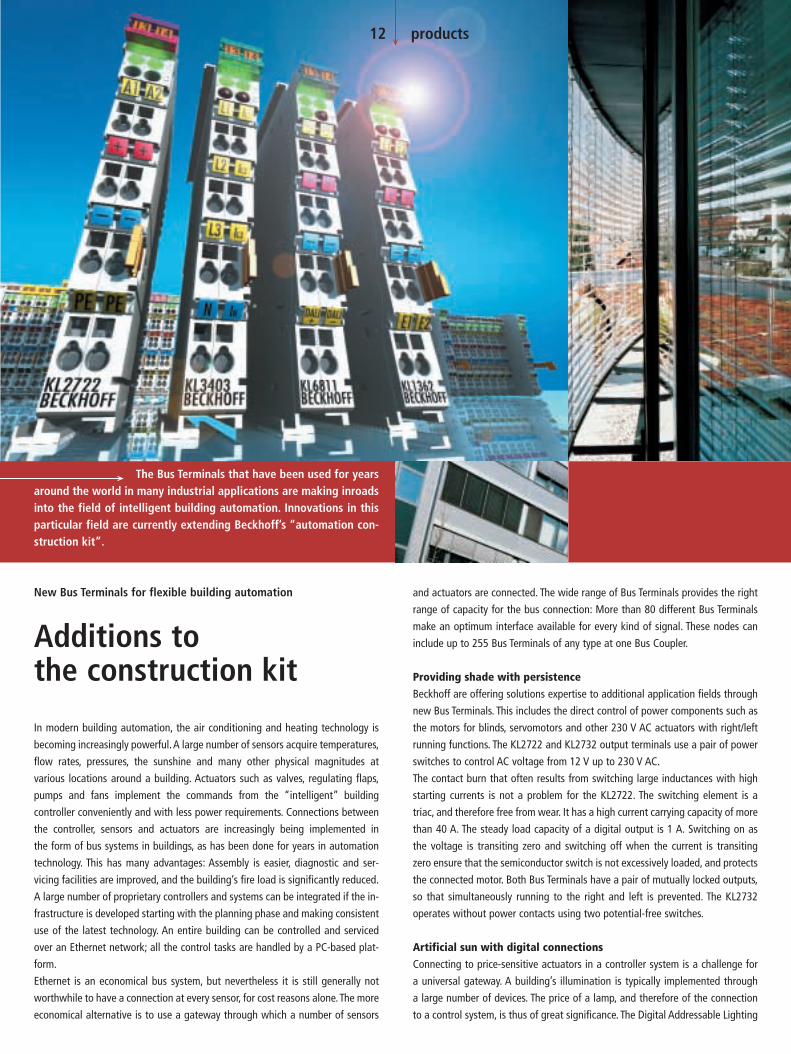
Providing shade with persistenceBeckhoff are offering solutions expertise to additional application fields through
new Bus Terminals. This includes the direct control of power components such as
the motors for blinds, servomotors and other 230 V AC actuators with right/left
running functions. The KL2722 and KL2732 output terminals use a pair of power
switches to control AC voltage from 12 V up to 230 V AC.
The contact burn that often results from switching large inductances with high
starting currents is not a problem for the KL2722. The switching element is a
triac, and therefore free from wear. It has a high current carrying capacity of more
than 40 A. The steady load capacity of a digital output is 1 A. Switching on as
the voltage is transiting zero and switching off when the current is transiting
zero ensure that the semiconductor switch is not excessively loaded, and protects
the connected motor. Both Bus Terminals have a pair of mutually locked outputs,
so that simultaneously running to the right and left is prevented. The KL2732
operates without power contacts using two potential-free switches.
Artificial sun with digital connectionsConnecting to price-sensitive actuators in a controller system is a challenge for
a universal gateway. A building’s illumination is typically implemented through
a large number of devices. The price of a lamp, and therefore of the connection
to a control system, is thus of great significance. The Digital Addressable Lighting
The Bus Terminals that have been used for yearsaround the world in many industrial applications are making inroadsinto the field of intelligent building automation. Innovations in thisparticular field are currently extending Beckhoff’s “automation con-struction kit”.
12 products
New Bus Terminals for flexible building automation
Additions to the construction kit

Interface, DALI, is a simple bus system for building automation that transmits the
signals for the digital operation of lighting devices. The lamp, sensor, button and
switching elements are wired in parallel, and are linked through the controller.
DALI offers two advantages: It is an economical interface, easy to install, and it
offers fully digital connection of lamps and comparable devices. The new KL6811
Master Terminal closes the gap between the lighting controller and the lamp, and
permits up to 64 DALI devices or DALI slaves to be connected.
The DALI Master is integrated into the Bus Terminal system as a normal Bus
Terminal, and is therefore independent of the fieldbus in use.The DALI data is then
passed on to the controller through the relevant Bus Coupler. When starting up,
the KL6811 DALI Master performs the search for addresses, and supports the user
in configuring his equipment. The 24 V supply unit integrated into the master
terminal supplies the DALI slaves with the appropriate voltage; no other ad-
ditional components are needed for operation. DALI is supported by most light-
ing control manufacturers. However other actuators, such as heating control
valves or the motors for operating blinds are increasingly being put under
digital control.
Digital alarm unitThe new KL1362 digital input terminal carries alarm signals in a very direct
format. This terminal analyzes the input signal from break-in sensors using a cur-
rent loop. Alarm contacts with a fixed resistance ratio can be monitored safely.
In the process image, the state of the sensor is indicated by one bit each. A fur-
ther bit reports short circuits or line interruptions. It is thus possible to use, for
instance, a BC9000 Bus Terminal Controller with Ethernet connectivity, to trans-
mit the alarm signals even over the Internet for remote diagnosis or remote alarm
purposes. This can include the subsequent reaction, in the form of appropriate
remote control signals used by actuators.
Power budget in the mains gridThe new KL3403 Bus Terminal for power measurement in three-phase networks
allows power management to be implemented using any fieldbus system. The
basic technical principle of the KL3403 Bus Terminal, which permits the meas-
urement of all the relevant electrical data in a three-phase power supply network,
is based on that of the KL8001 Power terminal. (See page 14 for further infor-
mation about the KL3403.)
The new Bus Terminals, along with the electronic terminal blocks already used in
many applications, permit a powerful and extremely flexible building manage-
ment system to be implemented. If extended by Beckhoff Industrial PCs and Con-
trol Panels, integrated solutions can be created reaching from the control station
out to the operation of pump drives, or linked over the Internet, and including
such features as seasonally dependent power management and daylight-respon-
sive illumination. Because building management, in contrast to applications in
factory automation, is characterized by the control of devices that are not highly
time-critical, Ethernet and web-based control concepts represent very flexible and
powerful platforms. Beckhoff’s control construction kit offers all the products,
components and tools needed from one source.
13 products
In version 4.0, Beckhoff are presenting a more devel-
oped version of their KS2000 configuration software.
The software allows for easy parameterization and rapid
diagnosis of the Bus Terminal system, and now includes
the Fieldbus Box product. The KS2000 software has
been completely reworked, and includes an entirely
new approach to data backups based on XML.
The most important innovations at a glance:
| Online monitoring: the state of an output changes
with a short click on the output terminal.
| Scope function for digital and analog values simpli-
fies setup and diagnosis.
| Ethernet bus couplers can be addressed directly
from the KS2000 software using a standard
Ethernet cable. Firmware can also be down-
loaded over Ethernet.
| If the bus stations are operated with a different
type of controller it is possible to print out the Bus
Terminal mapping information – making it easy to
map hardware points to memory locations.
| Complex bus terminals such as the AS-i Master
Terminal or the oscilloscope terminal can be para-
meterized easily by means of a dialog window.
New version of the
KS2000 configuration software
Estimated market release 1st quarter 2003.
We reserve the right to make technical changes.

Optimization of energy use has long been a desirable goal, for more reasons than
environmental conservation. Reduced energy consumption can be achieved
through active power management with the new KL3403 Bus Terminal. Measur-
ing and analyzing electrical current is the basis for monitoring and reduction
of energy consumption.
The measuring facilities and the compact form of the new KL3403 Bus Terminal
make it scaleable and economical for any power measurement task. Special
energy management systems, whose function revolves exclusively around moni-
toring power, optimizing consumption and load interruption can be extended by
the KL3403. A wide range of communication interfaces allows the terminal to be
integrated into very different systems.
Fieldbus-independent transmission of measurementsUsers can integrate expense/benefit optimization into their application by
using the consumption data obtained from the connected loads. This includes,
for instance, controlled switching on or off of electrical equipment, or statisti-
cal monitoring of electromotive consumers, leading to decisions related to
preventive maintenance. A significant benefit is the possibility of broaden-
ing power management from a local fieldbus segment up to the possibility
of global management functions.The KL3403 is operated like other Bus Terminals,
and the measurements taken can be transferred via the Bus Coupler to
various fieldbus systems, or, for instance, over Ethernet, to higher level control
systems.
The possibilities of power management are of particular interest in the field
of building automation. It can, for instance, be counter-productive for heating
units to continue operating in a building with controlled air-conditioning at
the beginning of the working period, when electrical consumption is running
at a high level. The electrical power consumption can be used to provide
“pre-regulation” to the heating controller, so that the increased production
of heat does not inevitably lead to increased power consumption in the cooling
system by the air-conditioning plant and fans. Hidden loads that unintentionally
remain switched on overnight and at the weekend can be tracked down through
the KL3403 Bus Terminal by detecting their consumption of electrical energy.
Correlation of production figures, numbers of staff on site, external temperature
and electrical energy consumption allow new possibilities for energy-saving
to be found.
Comprehensive network analysisThe new KL3403 Bus Terminal enables the measurement of all relevant three
phase electrical data. The voltage is measured via the direct connection of L1, L2,
L3 and N. The current of the three phases L1, L2 and L3 is fed via simple current
transformers. All measured currents and voltages are available as root-mean-
square values. In the KL3403 Bus Terminal, the effective power and the energy
consumption for each phase are calculated. All other information such as the ap-
parent power or the phase shift angle cos ϕ can be derived through the rela-
tionship of the root-mean-square values of voltage x current and the effective
power P. For each fieldbus, KL3403 provides a comprehensive network analysis
and an energy management option.
The basic technical principle of the KL3403 Bus Terminal is based on the KL8001
Power Terminal. The KL8001 Terminal, like a standard motor protection relay, is
fitted to a power contactor up to a switching capacity of 5.5 kW. The power
terminal switches the installed contactor and takes over all the functions of
the motor protection relay. The power terminal can also carry out numerous
diagnostic functions on the motor and make the information available to the con-
troller via the fieldbus. The same applies to the KL3403 Bus Terminal. A combina-
tion of switching and control is not, however, necessary for every application. For
this reason, only the measurement functions are integrated into the stackable
standard Bus Terminal.
A new three-phase power measurement Bus Ter-minal for the Beckhoff I/O system allows power management usingany fieldbus system.
Three-phase power measurement terminal extends I/O system
Power management withthe fieldbus terminal
14 products

L1
L2
L3
N
1 A 1 A 1 A
Energy management and analysis in the terminalThe KL3403 Bus Terminal supplies the necessary electrical data for power
management with “any” fieldbus connection similar to the KL8001 Power
Terminal which supplies the necessary data for motor management. The
KL3403 terminals data allows plant operators to control specific drives or ma-
chine components in an optimized manner, protecting them from damage or
failure.
In addition to straightforward measurements based on instrumentation
transformers, a wide range of diagnosis can be carried out with the KL3403
Bus Terminal. The mains voltage and phase angle are determined in addition
to the current measurement function. The KL3403 calculates the apparent
and active power of the loads that are actively connected from the voltage
15 products
u1
u1
u1
t
a) u1
t
b)
t
c)
u1
u1
Measurementinterval 2T
i
i
i
Types of current that can be measured:
The KL3403 can handle voltage and
current curves under phase control (a),
pulse duration control (b) and burst
firing control (c). For burst firing
control (c), the measurement interval
of the KL3403 is set to equal the
control interval, in thus case 2 T. The
KL3403 this always makes the current
value available – without the necessity
for further calculation.
and current. These values can be transmitted as instantaneous values, permitting
very rapid reaction to changes. The calculation of the true effective value in
the KL3403 Bus Terminal makes useful information available in the process
image, which does not presuppose high computing power on the part of the
controller. Even non-sinusoidal voltage and current curves can be read-in with
a practical accuracy of 1 % to 5%, depending on the type of curve. The cut-off
frequency of the calculations amounts to 2 KHz. As the time interval for calcu-
lating the values can be adjusted, optimization is possible under a very wide
range of circumstances.
The evaluation for each phase takes place independently. Adaptation for
a very wide range of currents is achieved through external current con-
verters. Failure of a conductor, or asymmetry in the current, is detected by
Developed on the basic principle
of power measurement terminals,
the KL8001 Power Terminal is also
a master of switching.

16 products
the KL3403 terminal, as is the fault current resulting from an earth short. The
usable resolution of 16 bits means that a difference of 10 mA can be reliably
detected when the full scale value is 60 A. The precision of the current measure-
ment is largely determined by the quality of the instrumentation transformer.
The use of electronic transducers also allows non-sinusoidal currents and DC to
be measured. It is possible to determine the effective value and the power
consumption of a load operating under phase control.
In-house energy counterThe KL3403 can be used as an energy counter for internal purposes. The counter
can be read at any time, although resetting, in contrast, is protected by a pass-
Bus Coupler connects I/Os with Universal Serial Bus
t
u i
iuu
ut
u i
ϕ
i
u
t
P
S
P
Complex current curves in a coil: The KL3403 determines the
root-mean-square value of the current along with the power
dissipation and the apparent power from the complex current
curve in a coil. It is possible to draw conclusions about the
quality, loading or mechanical magnitude.
Calculating the power: The apparent
power, S, is calculated from the pro-
duct u x i. This calculation is performed
64,000 times a second. The effective
power, P, is the mean of these values,
and depends on the phase angle, ϕ, in
addition to the amplitude of u and i.
The interval over which the effective
power is to be calculated can be
selected over a range from 5 ms up
to several seconds, depending on the
application. Periods of 5 ms, 10 ms,
20 ms or multiples of 20 ms are useful
for 50 Hz mains.
word. This information is retained in the KL3403 Bus Terminal even when the
power supply is switched off.
The KL3403 Bus Terminal is mounted on the mains voltage side. It can therefore
continue to measure the mains voltage if the load is switched off in the course
of power management. Integrated phase sequence monitoring protects against
serious equipment damage, and configurable switch-off and alarm thresholds
are used to monitor current and voltage. Critical conditions can be detected
promptly in this way, and damage can be avoided. Measuring the current by
means of transformers allows the installation at any location within the plant.
The KL3403 requires a 4-wire connection. The low internal resistance of 33 mΩminimizes transducer errors, and means that power dissipation is small.
The BK9500 USB Bus Coupler enables the integration of I/O signals without “real-time
demand” into the PC world. Application examples are general metrology, environmen-
tal engineering, laboratory applications, collection of operating data or data loggers,
among others. The advantage is that no additional hardware, such as PC card or inter-
face adapter, is required, since nearly all PCs have a USB interface. In the Full Speed
Version used, the transfer rate of 12 Mbaud is several times higher than with RS232.
The connection to the fast periphery bus is established via the standardized USB con-
nector, the distribution of the peripheral devices via hubs. A bus system with a maxi-
mum of 127 devices can thus be configured. System integration is straightforward
and is done via the TwinCAT System Manager from version 2.8 .

The AS Interface master terminal for 12 different fieldbus systems
For further and international sales contacts see: www.beckhoff.com
New Automation Technology
| BK1
1-10
E |
Beckhoff Bus Terminals | AS Interface Master | KL6201
The AS-i Masterin the Bus Terminal
Latest AS-i standard 2.1 Fieldbus-neutral coupling Compact design Up to 62 AS-i masters Comprehensive diagnostics
any Beckhoff Bus Coupler. The compact design and the option of usingseveral master terminals in a fieldbus station enables cost-efficient AS-iapplications.
The integration of the KL6201 AS-i master terminal into the Beckhoff BusTerminal system enables the integration of any number of AS Interfaceslaves into 12 different fieldbus systems. Due to the economic and simpleAS-i installation technology,periphery devices can easily be coupled with

Beckhoffs extensive Control Panel offering now includes six different display sizes
as well as a wide range of options for both form and function. The 640 x 480
pixels in the new 6.5 inch TFT display offer high-resolution in a small area. The
display is integrated into an extremely compact Control Panel housing, whose
resolution makes it easy to operate through Microsoft Windows, and still can
display easily readable text. Connection to the PC can be made by means of
CP-Link technology or DVI/USB interface. With CP-Link the PC can be up to 100 m
apart, or via DVI/USB, offering an economical solution for connections up to 5 m
apart. The Ethernet Control Panel offers a new option, where a 266 MHz proces-
sor PC is integrated into the 38 mm deep housing. This location-independent ver-
sion can be operated as an independent PC or as a terminal client to a Windows
terminal server.
18 and 20 inch TFT displays for complex visualizationsThe new 18.1 inch TFT display, with its 1280 x 1024 pixels, offers a large working
area for the display of complex graphics and for the presentation of detail images
Beckhoff has expanded the Control Panel and Panel-PC series by adding 6.5 inch, 18.1 inch and 20.1 inch TFTdisplays. The displays come in two styles, robust aluminum housing, types. The CP7000 series for wall or support bracket mounting has IP 65 splash proof rating protection on all sides. The design of the Control Panel CP6000 is intended for control cabinet mounting andmeets IP 65 at the front and IP 20 at the rear.
18 products
Extending the product range, upwards and downwards
New display sizes for the Control Panel family

at high resolution. The larger version, a 20.1 inch TFT display with a resolution of
1600 x 1200 pixels, has a 24 bit color depth, corresponding to 16.7 million colors.
The Control Panel picture remains sharp because of the digital connection tech-
nology. The user can choose from a wide range of available front designs; from
a display with no keyboard, optionally with a touch screen, up to a display with
a full PC keyboard and with customer-specific design. The 18.1 and 20.1 inch
Control Panels are connected to their PCs via a USB/DVI interface.
Many variations with the add-on PCIn addition to the options mentioned, all Control Panel types can be extended
through the use of the add-on PC to form a complete Industrial PC of compact
form. In the case of the built-in Control Panel series, the add-on PC CP63xx,
CP64xx or CP65xx, is mounted at the rear (additional information on page 10).
The Control Panel CP7000 for wall or bracket mounting can be extended by means
of an add-on PC CP7100 with a freely selectable front design. The Control Panel
and the add-on PC are built with robust aluminum housings, and are implemented
to IP 65 on all sides.
19 products
“Schneider/Télémécanique TeSys Model U
with Beckhoff Module”
Estimated market release 1st quarter 2003.
The KL8601 communication module, the KL8610
adapter terminal and the cable can be ordered
from Schneider Electric/Télémécanique or Beckhoff.
The motor starter can be ordered only from Schneider.
The fieldbus system can be ordered from Beckhoff.
We reserve the right to make technical changes.
Schneider Electric has introduced a newly designed product family
for protecting and switching motors within the “TeSys” product line.
Télémécanique TeSys Model U is a very compact motor starter that
can be connected directly with the Bus Terminal system via the KL8601
communication module developed by Beckhoff. Schneider customers
therefore benefit from almost unlimited fieldbus systems. Similar to the
KL8001 Power Terminal, the motor starter integrates seamlessly into
the Terminal Bus.
The motor starter is integrated into the fieldbus systems via a common,
shielded RJ45 cable and a new adapter terminal, type KL8610. The RJ45
cable can also handle the 24 V supply needed for the contactor. The
maximum distance between the KL8610 and the first motor starter
module is 5 m, the maximum distance between two starters is 0.5 m.
Up to 8 starters can be connected in series. Remote mounting of I/O
and power components is thus possible within the control cabinet. The
user is provided with a true “Plug & Play” solution.
This cooperation leads to a significant expansion of the range of Beckhoff
Power Terminals. Additional information in the next PC Control issue.
www.schneider-electric.com

Ethernet takes the next step as a “fieldbus” in Beckhoff’s TwinCAT control system. In addition to tough real-time require-ments, it permits the use of standard components “on the same wire”. The BK9000 Ethernet Bus Coupler and the AX2000-B900 servoamplifierare the first fieldbus components to benefit from the real-time capability. New network variables accelerate the real-time data exchange between controllers, making it as easy to implement as connecting another digital input.
Beckhoff’s range of Ethernet products has been in use for years, and is becoming
increasingly popular. The advantages of using the office Ethernet standard com-
munication method in industrial settings are clear:
| Standard hardware components can be used
| Standard protocols can be employed
| Data transmission rates are high
| Linking the network to the rest of the world
over the Internet is straightforward
| Remote maintenance and diagnosis
Communication over Ethernet has now become accepted in industrial automa-
tion and many groups and committees are concerning themselves with this
topic. The absence of effective real-time capability, however, is a problem, which
has limited Ethernet’s use in the classical fieldbus area. Some techniques do
allow a certain degree of real-time capability, but are based on proprietary
systems, and do not allow standard components and protocols to be used at
the same time.
“Real-time capability” is a somewhat flexible term when used in control theory.
“Real-time” depends heavily on the requirements of the particular application
and the control loops in which the automation components are used. However,
from the point of view of automation engineering, and against the background
that fieldbus specialist Beckhoff have to offer, a rough division can be drawn:
| The toughest requirements involve cycle times of around 50 µs and permis-
sible jitter (deviations from the desired cycle time) of around 10 µs. Require-
ments tighter than this are currently still handled with the aid of special
hardware rather than directly over fieldbusses.
| Typical cycle time requirements with position-controlled drives are in the range
of milliseconds (1-4 ms), in which case jitter times should be less than 20 µs.
| Pure PLC applications often require cycle times no shorter than 10 ms; cor-
respondingly, jitter times may here be significantly longer, and lie in the
millisecond range.
| Data communication between the controller and the supervisory system can
often satisfactorily be handled with cycle times in the range of seconds. In
fact it may not be configured cyclically, but may be event driven.
20 products
Ethernet communication in real-time

TwinCAT I/O TwinCAT I/O
TCP/IP(original Windows Stack)
NDIS Protocol
TwinCAT I/O
Process Images
NDIS Miniport NDIS Miniport
EthernetController
e.g. ProfibusMaster
EthernetController
21 products
Servoamplifier with Ethernet
interface AX2000-B900
Ethernet Bus Coupler
BK9000
Ethernet’s operating principle
| Remote servicing and diagnosis should also be mentioned. Cycle and jitter
times here are less relevant than reaction times and the general possibility
of being able to communicate across the boundaries of networks.
TwinCAT automation software now offered with Real-time Ethernet means that
all the communication requirements that have just been mentioned can be satis-
fied using one and the same technology, both from the point of view of the
devices used and of the protocols employed.
Principle of operationThe TwinCAT network card driver is linked into the system in such a way that it
appears as a network driver, compatible with the operating system, and addi-
tionally as a TwinCAT fieldbus card. An internal prioritization system and buffer is
provided at the transmitter end which always finds a free transmission channel
for Ethernet frames from the real-time system that may be queuing.The operating
system’s Ethernet frames are only later transmitted in the “gaps” if sufficient time
is available.
At the receiving end, all the Ethernet frames received are examined by the
TwinCAT I/O system, and those with real-time relevance are filtered out. All
other frames are passed on to the operating system after examination, outside
the context of the real-time system. Using commercially available switches, all of
which support full duplex operation at 100 Mbaud, the transmitted frames are
passed on to the receiver with a constant delay. A switch ensures that collisions
are avoided and only delays occur. In a cyclic control system it is therefore only
necessary to ensure that all the relevant input information has arrived before the
next cycle starts. When, or in what sequence, they have arrived is not significant.
If the number of participating devices or the frame rate is restricted in accordance
with the required cycle time, the preconditions for Ethernet communication with
real-time capability are satisfied.
Operating modes/protocolsIn contrast to the widely used TCP/IP and UDP/IP protocols, which are responsible
for the provision of individual Ethernet frames around the world, real-time com-
munication does not leave the local subnet. The overhead involved in TCP/IP, and
even that of UDP/IP, can be omitted, and the devices can be addressed directly by
means of the hardware addresses (MAC-ID) of the network cards. The structure
of Ethernet frames ensures that it is always possible to co-exist with other pro-
tocols; even the “real-time frames” can, if necessary, be transmitted with TCP or
UDP, if they have to leave their own subnet.
A number of different operating modes have been defined for use in control
engineering. They serve different communication tasks, and can, of course, be
employed simultaneously.
| Master-slave process data communication
Cyclic or event-driven transmission of I/O data – the typical use of modern
fieldbusses
| Publisher-subscriber process data communication
Process data according to the publisher-subscriber model (also referred to as
network variables) is used for regular communication between controllers
when a fixed master-slave relationship would not be appropriate. The pub-
lisher sends out its information without concerning itself with where it is
going. The communication is only monitored in the subscriber. Mutual pub-
lisher-subscriber relationships permit bi-directional and multi-directional
communication. The publisher can be configured to send the data by broad-
cast, multicast or unicast. Multicasts reduce the loads at the network devices’
receive queues, because the messages are evaluated as soon as they reach
the Ethernet controller. Only if unicasts are used the switch (without extensive
configuration) can open parallel communication paths and increase the
useful bandwidth.
| Data communication as required
This is a type of communication made possible in the TwinCAT system through
ADS communication, and which sends communication strings from one
device to another “as required”. Services are executed and parameters
exchanged in this way.
The chosen protocol structure means that other operating modes or communica-
tion profiles can easily be integrated in the future, and can co-exist with the
existing modes without difficulty.
Compatible componentsThe first components from the Beckhoff product range to have been extended
for real-time Ethernet application are the BK9000 Ethernet Bus Coupler and
the AX2000-B900 Drive Controller. These two components open up almost the
entire range of industrial signals and applications.
All TwinCAT controllers (from Version 2.9 onwards) are compatible, and can
participate both as “fieldbus masters” and in communication using network
variables. TwinCAT supports all Ethernet controllers of the Intel 8255x family. This
is one of the most widespread Ethernet controllers, a component in the latest
Intel chip set, which already include a compatible network connection. Support
for further Ethernet controllers in the future may be considered – in the
light of the wide popularity of the Intel family and its compatibility even with
Gigabit Ethernet (Intel 8254x family) – but not absolutely essential. The new
Embedded-PC CX1000 small controller is, of course, always fitted with an appro-
priate Ethernet controller.

Switch
Ethernet Bus Coupler BK9000
Ethernet Control Panel
Servoamplifier AX2000
Ethernet22 products
Switch
AX2000
BK9000 BK9000 BK9000 BK9000
AX2000
Industrial PC
Control Panel
Industrial PC
EthernetControl Panel
Switch
Ethernet Bus Coupler BK9000
Industrial PCControl Panel
BK9000 Servoamplifier AX2000
Ethernet
Application example 2: Larger applications make use of a second Ethernet connection, and
divide the real-time communication and the higher level communication between two net-
works. The routing that is required in order, for instance, to remotely diagnose a drive that
is connected to a real-time network is performed automatically by the operating system’s
IP stack, and does not require any proprietary conversion to a different protocol.
PerformanceJudging the performance of a fieldbus system exclusively on the basis of the baud
rate is, without doubt, too simple, ignoring as it does other significant communi-
cation parameters such as the efficiency of the protocols, reaction time, jitter,
minimum telegram length, pause times and so forth. All the same, 100 Mbaud
permit significantly faster data transfer than is usual at present in fieldbus en-
vironments. In addition to this, the protocols used provide a significantly im-
proved efficiency in contrast with TCP or UDP communication, in particular when
data telegrams are short.
One factor which is often ignored when considering the capacity of a fieldbus
system is the transfer of data between the controller CPU to the communication
chip or processor; that is to say, between the host system memory and the sub-
system memory. In PC based controllers, the data is usually copied over the ISA
or PCI bus into the DPRAM of a fieldbus master card, and vice-versa. Whereas PC
processors have reached speeds of around 3 GHz, even the supposedly fast PCI
bus has become a bottleneck, so that 20-30 % of the CPU performance is lost for
PCI transfers.
Modern network controllers operate in what is known as the “bus master DMA
mode”, accessing the host system’s memory directly. This occurs in parallel with
other CPU tasks, and therefore significantly reduces the CPU load.
Applications/Linking to TwinCATThe high data transfer capacity, the fundamental real-time capability and the pro-
tocols that are employed cover all the communication demands made by a fast
machine controller. When all these features are considered we are soon led to the
conclusion that classical fieldbusses are not longer needed.
First of all, however, Ethernet technology must still be proven at the field level,
and must meet all requirements such as those for simplicity of installation and
configuration, mutual compatibility, EMC immunity and, not least, efficiency and
device costs relevant to the industrial environment. Standard fieldbusses are
widely accepted, and there are many devices offered by many vendors including
Beckhoff. Therefore, they will continue to have great significance to the market.
Here once again, TwinCAT’s flexible I/O system offers a way forward: It permits
multiple fieldbusses to be operated in parallel, including, of course, the parallel
operation of classical fieldbusses with real-time Ethernet – and all of this is
entirely transparent to the application.
Application example 3: Very large applications, for which the computing power even of a
3 GHz system is insufficient, can distribute the control tasks between a number of PC con-
trollers, and can exchange even large amounts of data quasi-synchronously with the cycles,
(even at sub-millisecond speeds) using the real-time capable network variables.
Application example 1: Relatively simple applications can manage with a single Ethernet
connection, both for the real-time communication to the I/O level and for the higher-level
communication for the purposes of administration and remote diagnosis. The prioritization
that is used ensures that the real-time communication takes place without difficulty.
Configuration with the
TwinCAT System Manager

A
B
N-I t
Pulse patternMagneticEncoder System
Linear MotorAL2000 Series
Pulse pattern of
the magnetic field
measurement for the
permanent magnets
uring section. Linear motors are also increasingly
used, for example, in gantry systems involving
large distances. Here, the additional expenditure
for the displacement measuring system is ex-
cessive and may make the whole machine con-
cept financially questionable. Costs are also the
reasons why the use of the above systems is
often not justified for other applications with
moderate precision requirements, for example
for wood or Pick & Place machines.
For this reason, automation specialist Beckhoff
has developed a measuring system that moni-
tors the magnetic field of the permanent mag-
nets of the magnetic plate and provides the
AX2000 series servoamplifier with incremental
transducer signals for commutation, speed and
position control. The measuring system provides
1000 increments per logical motor revolution.
A logical motor revolution corresponds to the
distance between two homopolar magnets, i.e.
for example between two north poles. With
24 mm, this distance is very short for the AL2000
series linear motors, resulting in very high re-
solution. This leads to particularly synchronous
operation and low running noise.
The operation of synchronous servomotors re-
quires a feedback system for acquisition of the
rotor position and speed for the commutation.
Traditionally, a tachometer and a rotor position
encoder have been used for this purpose. For
some time now, resolvers enabling sinusoidal
power supply of the synchronous motor have
started to replace this system. The resolver is
complemented by further possible feedback sys-
tems such as incremental transducers, absolute
encoders, etc.
For the operation of linear motors, the feedback
system is installed parallel to the travel path. It
consists of a reader head, usually mounted on
the motor slide, and a scale mounted parallel to
the travel path. A distinction is made between
absolute and incremental systems; both are sub-
divided into magnetic and optical systems, with
precision and sensitivity playing a crucial role.
Magnetic encoders do not quite reach the reso-
lution of the optical models, but they are slight-
ly cheaper.
However, the displacement measuring systems
described above have the disadvantage that
their costs increase with the length of the meas-
Scaleless feedback system for linear motors AL2000
Innovation for linear drives
Estimated market release
1st quarter 2003.
We reserve the right to make
technical changes.
A resolution of 0.1 mm is adequate forsimple positioning tasksA maximum resolution of 24 µm is adequate for
simple positioning tasks. The achievable preci-
sion ranges between ±0.1 mm and largely
depends on the mechanical precision and
position of the travel path magnets. The influ-
ence of temperature fluctuations and external
interference fields is compensated.
However, the crucial advantage is the absence of
the scale; this means no comprehensive align-
ment and installation is required, since the
measuring system can be mounted directly on
the motor. If the travel path is extended, no
reinstallation or replacement of the scale is
required. The magnetic encoder system for
AL2000 series linear motors is only 36 mm wide
and is mounted in front of the linear motors. The
process is further facilitated by the use of pre-
assembled cables. This means that the price
remains constant, no matter what measuring
length is required. Another advantage is the
maximum possible travel path. With AX2000
servoamplifiers, this is 50 m.
In drive applications, linear servomotors are popular due to their excellent characteristics in terms of dynamics and synchro-nous operation. They are particularly advantageous if the installation of rotary motors is not possible due to the mechanical specification. The linear motors are not subject to mechanical wear and are easy to commission. These advantages are partly weakened by the higher costs for thefeedback systems. The new magnetic encoder system from Beckhoff complements the linear technology market with an inexpensive alternative. Thefeedback system for the AL2000 series linear motors is scaleless and therefore independent of the length of the magnetic plates.
23 products23 products

copying. In version 2.9 it is possible to co-ordinate the work via a source code
management system. To this end, the Engineering Interface (ENI) Server is in-
stalled on a central server. It provides a shell for a variety of source code
management systems. Under this shell, Microsoft Visual Source Safe or MKS
Source Integrity may be operated.The creation of individual drivers for other tools
is possible. In the PLC development environment, a certain version of a project or
a component can be called up from the database. For processing the component,
the object must be checked out. This means that it is locked for all other users.
Once processing is complete, the object is checked in again. The history of
all formerly generated versions of an object can be called up at any time. Com-
parisons of different versions are possible.
COM interface for software PLCAll commands that were previously made available via the batch interface are
now also accessible via a COM interface. These commands can thus be executed
from a Visual Basic program, a Delphi program or simply via a Visual Basic script.
Some additional commands make the use of the batch interface even more
convenient. Within a batch, wildcards now exist for the current project and
for various paths.
Today’s control technology still has plenty of potential for savings in terms of its engineering. TwinCAT 2.9 meets these requirements. The further development of the engineering tools tackles the increasingly more complex automation. New features make confi-guration and programming significantly easier. Existing software components are reused easier, commissioning time is shortened, costs are reduced.
Configuring and commissioning with configuration modeThe new TwinCAT 2.9 configuration mode further simplifies the commissioning
of I/O signals and axes. Initial commissioning can be carried out without PLC
program. In configuration mode, all Beckhoff fieldbus components can be
operated free running. Inputs can be read and outputs set in Force mode. Faults
can be detected and rectified at an early stage. In addition to determining the
existing fieldbus cards in the PC, it is also possible to read the individual nodes
and existing Bus Terminals for all fieldbusses. Configuration errors can thus
be prevented.
Version 2.9 of the TwinCAT System Manager can also be operated remotely. This
means that a TwinCAT system that can be reached via TCP/IP can now be
programmed and commissioned not only via the PLC control, but also with the
TwinCAT System Manager. Systems can thus be conveniently configured remote-
ly, using the familiar configuration and diagnostic tools of the System Manager.
Engineering InterfaceIn cases where several programmers work on a PLC project, in the past the ques-
tion kept recurring of how to integrate the work of the different programmers
in a single project. Up to now, this was only possible by comparing, importing and
TwinCAT automation softwareversion 2.9
Complex automationmade simple
24 products

25 products
TwinCAT 2.9 will be available from December 2002
at www.beckhoff.com
TwinCAT Valve Diagram Editor
In order to linearize non-linear characteris-
tic curves of hydraulic valves, a velocity
curve that has been measured for the out-
put voltages has to be read in and approxi-
mated by a characteristic curve. The meas-
ured characteristic curve is displayed in
the TwinCAT valve diagram editor and can
easily be linearized graphically. Only a few
reference points are required. A straight
line or a 5th degree polynomial are placed
between these reference points. The deter-
mined characteristic linearization is then
loaded into the TwinCAT NC real time and
taken into account when the voltages are
output in the drive. Online monitoring is
possible at any time.
External set value generation for TwinCAT NC PTPThanks to the new external set value generation option, from TwinCAT version
2.9, it will be possible to superimpose own set value generators, written in the
PLC, or different set value generators with the standard set value generator of the
NC PTP. This opens up a variety of new applications. On the one hand, special set
value generators that are optimized for a certain application can be written in the
PLC. On the other hand, interpolating movements of several axes can be com-
bined with NC PTP features such as the flying saw. CNC machining of moving
workpieces can thus be realized. The handling of the new function is supported
by a number of new PLC components.
Motion laws in real-timeThe increasing performance of PCs means that the complex motion laws de-
scribed in VDI 2143 can now be calculated directly at NC runtime. This has
numerous advantages. On the one hand, only very few reference points have to
be transferred into the TwinCAT NC real time. While previously several thousand
reference points had to be transferred, today a few are sufficient. Existing points
can be modified online, or the laws associated with the points modified. This
enables very flexible cam plate applications.
TwinCAT NC I newsIf, for example, the saw blade is found to be blunt and has to be replaced during
a sawing process, the new NC-I emergency stop is activated. After the saw blade
has been replaced, the axes are repositioned, and the part program continues
where it stopped once the stop function is released. The emergency stop can stop
with parameterizable, even high decelerations. After the stop function has been
released, the part program can continue to be executed immediately.
The retrace function interrupts the execution of the current part program, and
the program is processed in reverse order back to the start, if necessary. If, for
example, a thread breaks in a sewing program during the execution of a part pro-
gram for sewing clothes, then the path needs to be partly retraced and the pro-
gram restarted at the right position.
Source code management via Visual
Source Safe or MKS Source Integrity
TwinCAT Valve Diagram Editor

Comparing fieldbus systems topology in production applications is secondary for
analyzing the performance parameters: The differences in physical propagation
times of bus, ring and tree structures are comparatively small. However, the baud
rates and particularly the protocol efficiency are significant. In cyclic systems, this
is particularly relevant for the overall cycle time.
System structureLet us take a closer look at a control system with decentralized fieldbus devices.
The control (e.g. an IPC or a PLC) cyclically executes one or several application
programs (e.g. Motion or PLC tasks). The fieldbus interface is designed as a plug-in
card with a dedicated processor. Process data are exchanged with the control via
a shared memory area (DPRAM-Dual Port RAM), which is accessed alternately.
The simplest – and most common – communication principle for fieldbus systems
is cyclic data exchange between a central fieldbus master and many decentralized
fieldbus slaves. In this context it is initially irrelevant whether the data exchange
and the bus access occurs via polling (e.g. Profibus), via time slicing (e.g. Sercos)
or via the shift register principle (e.g. Interbus). Even the CAN-based DeviceNet,
with bus access according to the multi-master principle, is nearly always a polling
system at the protocol level and can therefore usually be treated as a cyclic field-
bus. A CANopen system, typically using event-driven communication in multi-
master mode, can be operated in strictly cyclic mode – e.g. for controlling axes.
For the general fieldbus systems under consideration, the controllers’ fieldbus
interface acts as the master that controls the bus cycle. Correspondingly, the
decentralized fieldbus devices are slaves. They only respond to requests from the
master and can therefore communicate new input data only in line with the
bus cycle.
Fieldbus cycle timeThe cycle time of the fieldbus systems is the best-known parameter. It predo-
minantly depends on the baud rate and the protocol efficiency. The Figure “Bus
cycle” provides an overview of typical cycle times for some fieldbus systems,
depending on the baud rate, the number of devices and the number of data bytes
exchanged. Naturally, these calculations are based on several assumptions: For
DeviceNet, a bus load of 80% was assumed for pure polling operation. For
Profibus, a delay of 0.3 ms was assumed between two cycles (e.g. for accessing
the DPRAM). The protocol time constants (e.g. the station response time) for
typical devices also had to be estimated.
Master cycle delay/Master firmware cycleAn intelligent fieldbus control interface with dedicated processor has been as-
sumed. This fieldbus master copies the process output image to the slaves via
the fieldbus and gathers the input data. The input process image is copied to
the DPRAM of the control.
For reasons of data consistency, in most implementations the input process
image is only copied to the DPRAM of the control once it is complete. In a cyclic
fieldbus system, therefore, this only occurs once the fieldbus cycle is complete.
Copying of the input data may also be delayed, because initially enabling of
the DPRAM has to be awaited. Delay times in fieldbus masters typically range
between 0.1 and 3 ms.
26 products
Cycle time is not everything
Performance of fieldbus systems in production applications
The performance of fieldbus systems in production applications is often described in terms of the achievable communicationcycle times. The real-time capability of the different systems is then often assessed based on these figures. Other approaches also take into account the repeatability of the communication cycles. However, more critical parameters are usually ignored, such as the synchronization behavior of both the central control applications and the subordinate, decentralized application parts with the fieldbus cycle.
Slav
e
I/O
ControlSystem
Task
FieldbusInterface
DPRA
M
Master
System Architecture
Slave
I/O
Slave
I/O
Slave
I/O
Field-bus
Slav
e
I/O
Slave
Drive
Bus Cycle Times
3.3
DeviceNet500 kBaud10 Slaves
DeviceNet500 kBaud20 Slaves
Profibus12 MBaud10 Slaves
Profibus12 MBaud20 Slaves
Sercos4 MBaud10 Slaves
Sercos4 MBaud20 Slaves
20
15
10
5
[ms]
4.9
15.5
31.0
9.8
6.6
0.60.5 0.9 1.50.90.71.61.00.8
3.01.61.2
2 Byte I + 2 Byte O/node
6 Byte I + 6 Byte O/node
20 Byte I + 20 Byte O/node

Control cycle time (“task”)The fieldbus performance should normally reasonably match the performance of
the associated control. For typical applications, a sensible parameter is the cycle
time of the associated control task.
For PC-based control systems, task cycle times of well below 1 ms are achieved
due to the high performance of the PC processors. This is particularly useful for
fast tasks, such as axis control. For typical PLC applications, cycle times between
2… 10 ms are usually chosen.
For “classic” PLC solutions, typical cycle times of 10… 20 ms are still common.
Slave cycle delay/Slave firmware cycleIn most fieldbus systems, the slave devices also have a processor with associated
firmware. This is polled cyclically by the fieldbus master and then queries the in-
puts and copies the output data to the outputs.
Modular slave devices such as the Beckhoff Bus Terminal system have a local bus
that connects the I/O modules with the actual fieldbus device, the Bus Coupler.
Depending on the configuration, a complete update can take between 0.1… 2 ms,
even with the very fast Beckhoff K-bus.
But even for devices with fixed configuration, the local firmware cycle cannot be
ignored – the inputs are queried and the outputs updated according to its cycle.
Interfaces: Synchronization or free runningThe typical fieldbus system under consideration is a multi-processor system with
a large number of interfaces. The programs on the different processors usually run
cyclically, in rare cases event-driven (interrupt-driven).
The simplest operating mode for the processes is free running: Decoupled via a
shared memory area, both cyclic and event-driven processes can be processed
largely independent from each other. The fieldbus itself can also be interpreted
as a distributed shared memory area.
Alternatively, the different processes may be synchronized. For the slave side this
means that the firmware cycle or the local bus cycle is synchronized with the field-
bus cycle.The outputs of an I/O module are immediately updated once the new out-
put data is received from the most recent fieldbus cycle. The input data is imme-
diately read by the local slave but not communicated until the next fieldbus cycle.
Of particular interest is the synchronization of the fieldbus master with the con-
trol. In fast bus systems, fieldbus cycle and control task happen one after the
other, so that the control task receives current input data each time. The outputs
are written directly after completion of the control task with the next fieldbus
cycle. For very fast control tasks (e.g. NC tasks for axis control) or relatively slow
bus cycle times, the input and output data can be copied at the start of the con-
trol task, and the bus cycle can run at the same time as the control task. In this
case the input data is from the previous bus cycle. Therefore, the control task does
not have to wait for the current bus cycle to be completed.
The effects of the parameters on the response time and the determinism of the
system are described below with the aid of various example configurations.
Scenario I: Continuous free running, “medium-fast” bus systemIn this scenario, the bus cycle time is similar to the task cycle time. The fieldbus
cycle is free running relative to the control task. The local I/O cycle is not syn-
chronized with the bus cycle either.
We will now look at the response time to an arbitrary input signal. In the worst
case, the input signal changes straight after the local I/O cycle has queried the
inputs (or is just passing through the hardware input filter). The system must
wait for the next local firmware cycle, until the firmware of the decentralized I/O
node has detected the event. However, it can communicate this information
only during the next polling of the input data through the fieldbus – in the worst
27 products
PLC Task OI
Bus Cycle Bus Cycle Bus Cycle Bus Cycle Bus CycleBus CycleCycle
T mdv
T I/O T I/O T I/O T I/O T I/O T I/O T I/O T I/O T I/O T I/O T I/O T I/O T I/O T I/OT I/O
PLC Task OI PLC Task OI PLC Task OI PLC Task OI
Input(best case)
Input(worst case)
Output
Tmdv : Master Processing DelayTI/O : Local I/O Update Time (Firmware)
Reaction Time I Reaction on digital Input(Typical for: AllenBradley PLC | DeviceNet)
worst case reaction timebest case reaction time
case it will have to wait for a whole fieldbus cycle.
Once the fieldbus cycle is complete, the input information is in the fieldbus
master, i.e. in the scanner module of the control. The master copies the data
into the DPRAM of the control and then releases the DPRAM – the time required
is the master cycle delay. In the worst case, in a free running system the control
task will start before the master module releases the DPRAM, i.e. the input
data are not processed by this task. It will therefore take another complete
control task until the input data in the DPRAM is read and processed by the con-
trol task. In the worst case, we also have to assume longest time to write the
outputs: The control task does not finish before the start of the next fieldbus
cycle. Therefore the master module does not have the most recent output
data from the control task. In this scenario an additional fieldbus cycle has to
be awaited. The output data is now transferred and just misses the local I/O
cycle. As can be seen from the chart, with unfortunate timing the response time
in such a system adds up to > 4 bus cycle times or a corresponding number
of PLC task times. Even the jitter between ideal case and worst case – a measure
of the determinism of the system under consideration – is in the range of 2 PLC
tasks.

28 products
This shows that, in this case, the system-inherent determinism of the chosen
fieldbus can be ignored.
Scenario II: Continuous free running, faster bus systemWe will now try to speed up the system through a faster fieldbus: The “medium-
fast” fieldbus from scenario I is replaced with a fast fieldbus with only half the
cycle time compared with the first case. The complete system remains in free
running mode.
A comparison of the two charts reveals that, while the average response time has
improved by approximately 20-25 %, the “best case” is the same in both cases.
Overall a rather disappointing result, given that the bus was now twice as fast.
We also note that the input data of some bus cycles have not been processed –
they are overwritten by the next bus cycle, since no task has been started in the
meantime. Furthermore, only every second or third bus cycle transports new out-
put data. Whilst the fieldbus is faster, it is partly inefficient.
Scenario III: Master free running, slave synchronizedWe will now try to improve the result further by introducing synchronization
mechanisms. Initially, the slave firmware cycle or the local I/O update is synchro-
nized with the fieldbus cycle. This only leads to an improvement in the response
behaviour on the output side: The outputs are always updated directly once new
data have been received. The average improvement corresponds to half the
duration of a local firmware cycle on the I/O module. The determinism of the
system improves correspondingly.
Scenario IV: Fast bus, fully synchronizedThe fieldbus cycle is now also synchronized with the control task. The response
behavior on the output side is optimal, the outputs are set deterministically as
quickly as possible. Nevertheless, several task cycles (or bus cycles) still pass on
the input side, before the input information can be processed. While the deter-
minism of the system is good (it corresponds to the task time), the overall
response time remains unsatisfactory. It is also interesting to note that the faster
bus (1 ms instead of 5 ms) has done little to improve the response time.
Scenario V: Synchronized on the master side, free running slaveWhile free running slave firmware (relative to the bus cycle) is slightly disadvan-
tageous on the output side - the input side now also captures information arriving
between the “extended” bus cycles. For time conditions as shown in the graphs –
task slow relative to local firmware cycle – the response time in particular has
improved.
Scenario VI: Multi-tasking system, synchronized throughoutA further improvement of the response time – but mainly of the determinism –
can only be achieved by shortening the task cycle time. For a given CPU per-
formance, the simplest way of achieving this is via a multi-tasking control system:
The time-critical tasks are programmed in a short task, which is synchronized with
the (fast) fieldbus system. All other application parts can then be realized in
slower tasks.
This scenario offers optimum response times, and at the same time optimum de-
terminism. This is the usual system architecture of the Beckhoff TwinCAT control
system.
Tmdv : Master Processing DelayTI/O : Local I/O Update Time (Firmware)
Reaction Time III Reaction on digital Input(Typical for: Siemens PLC | Profibus I/O)
Input(best case)
Input(worst case)
Output
T I/O
PLC Task OI
T mdv
T I/O T I/O T I/O T I/O T I/O T I/O T I/O T I/O T I/O T I/O T I/O T I/O T I/O
PLC Task OI PLC Task OI PLC Task OI PLC Task OI
worst case reaction timebest case reaction time
Cycle Cycle Cycle Cycle Cycle Cycle Cycle Cycle Cycle Cycle Cycle Cycle Cycle
worst case reaction timebest case reaction time
Input(best case)
Input(worst case)
Output
Tmdv : Master Processing DelayTI/O : Local I/O Update Time (Firmware)
Reaction Time IV Reaction on digital Input
PLC Task OI PLC Task OIPLC Task OI
T mdv
T I/O T I/O T I/O T I/O
FB FB FB FB
PLC Task OI PLC Task OI
PLC Task OI
T mdv
T I/O
Cycle
T I/O T I/O T I/O T I/O T I/O T I/O T I/O T I/O T I/O T I/O T I/O T I/O
worst case reaction timebest case reaction time
PLC Task OI PLC Task OI PLC Task OI PLC Task OI
Reaction Time II Reaction on digital Input(Typical for: Siemens PLC | Profibus, AB | ControlNet)
Input(best case)
Input(worst case)
Output
Tmdv : Master Processing DelayTI/O : Local I/O Update Time (Firmware)
T I/O T I/O
Cycle Cycle Cycle Cycle Cycle Cycle Cycle Cycle Cycle Cycle Cycle Cycle

29 products
Scenario VII: Event-driven communicationUp to now, we have considered cyclic bus systems. Some systems – e.g. CANopen
or DeviceNet – can also be operated in event-driven mode. In DeviceNet, this
mode is called “Change of State”. A change of an input is regarded as an event
and is communicated automatically, without request by a master.
The results of measurements for a CANopen system with event-driven communi-
cation: Despite a comparatively low baud rate (500 kBaud), the response time ap-
proaches that of a comparable Profibus system. However, the Profibus system
shows this response time for all inputs, while in the CANopen system delays will
have to be expected with high bus loading.
Results A comparison of the different scenarios provides the following results:
| The performance of a fieldbus-networked control system cannot be deter-
mined via a single parameter.
| The pure cycle time of the chosen bus system is usually secondary. Even for
the assessment of the real-time behavior of the bus system, the cycle time is
only partly useful: In many cases the synchronization behavior is the crucial
factor.
| In most cases, the cycle time of the control is more important than the cycle
time of the bus system: Even with a fast fieldbus, a slow control will not
achieve real performance.
| The following generally applies for the fieldbus cycle time: “Fast enough”
means faster than the cycle time of the control.
| Synchronization initially improves the determinism of the system, but not
necessarily the response time.
| Bus systems with event-driven communication have very short response
times.
| An optimum response time with low jitter can only be achieved by tuning the
system. This requires knowledge of the different temporal factors – and a sys-
tem that permits such “tuning”.
| A short response time is only one of several criteria for determining the sys-
tem performance. For many applications, the determinism of the system may
be the crucial factor.
SummaryFor determining the performance of a fieldbus system, the bus cycle time is only
one of many parameters. Other important parameters are the synchronization
behavior and the fieldbus firmware cycle times on the master and slave side.
Knowledge of the control cycle times is very important for selecting a suitable bus
system.
Some typical scenarios serve to describe the interrelationships of the parameters.
The scenarios prove that the bus cycle time alone can only provide an estimation
of the achievable response times and determinism – and thus about crucial real-
time characteristics. The synchronization mechanisms of modern fieldbus systems
can also be applied usefully outside drive communication applications.A fully syn-
chronized communication system improves the determinism, but not necessarily
the response time. The optimum choice or tuning of the bus system always re-
quires an analysis of the real-time requirements: Different parameters have to be
chosen, depending on whether the application to be solved is determined by re-
sponse time or determinism.
Martin Rostan, Product Manager Fieldbus Systems
Input(best case)
Input(worst case)
Output
Tmdv : Master Processing DelayTI/O : Local I/O Update Time (Firmware)
Reaction Time V Reaction on digital Input
T mdv
T I/O
PLC Task OI
FB FB FB FB
T I/O T I/O T I/O T I/O T I/O T I/O T I/O T I/O T I/O T I/O T I/O T I/O T I/O T I/O T I/O T I/O T I/O T I/O T I/O
SPS Task OI PLC Task OI PLC Task OI PLC Task OI PLC Task OI
worst case reaction timebest case reaction time
Input(best case)
Input(worst case)
Output
Tmdv : Master Processing DelayTI/O : Local I/O Update Time (Firmware)
Reaction Time VI Reaction on digital InputPossible with: Beckhoff TwinCAT | Profibus | Sercos
PLC Task OIPLC Task OI
T I/O
PLC OI
FB
PLC Task OI PLC Task OI PLC Task OI
T I/O
PLC OI
FB
T I/O
PLC OI
FB
T I/O
PLC OI
FB
T I/O
PLC OI
FB
T I/O
FB
T I/O
PLC OI
FB
T I/O
PLC OI
FB
PLC OI
worst case reaction timebest case reaction time

30 special | Fieldbus Box
The “Special Fieldbus Box” con-tains the Beckhoff I/O system in protection class IP67, which was developed as an extension to the BusTerminal system in IP 20. The robust, fully pottedhousing enables operation at machine level.
31 | Fieldbus Box modules in action in a
continuous casting plant at SMS Demag AG
34 | Waterproof mini-PLC with compact design
Fieldbus Box Module with integrated T-piece
35 | I/O modules with protection class IP 67
for more competitive production
at Leonhard Moll Betonwerke GmbH & Co.
38 | IP-Link interface connects Festo CPV
valve terminal to the I/O environment

SMS Demag AG, headquarted in Germany, is an internationally leading manu-
facturer of metallurgical plant and rolling mill equipment. The company has been
active for nearly 200 years and develops, constructs and builds machines and
plants for the steel, aluminum and copper industries around the world. The range
includes both system and automation solutions for the complete process chain,
from iron making via steel plant, continuous casting, rolling mill and pipe tech-
nology to finishing lines for hot and cold rolled strip.
The continuous casting plants are used for the production of steel slabs that can
be further processed into flat steel bars, so-called coils or wires, for example in
rolling mills. The steel is liquefied in a blast furnace and vertically poured into a
mold. The mold is the first part of a continuous casting plant and is decisive for
the shape and first solidification of the subsequent product. The profile is almost
rectangular; the length in the direction of production is approximately 1 m. On
the inside, the mold is clad with copper plates that are equipped with thermo-
couple sensors for measuring the temperature.
During the start of casting, the mold is closed at the lower end with a dummy bar
head, so that a stable skin can form in front of the plug and at the sides. Once
this has solidified, the plug is removed and the slab is turned horizontal via appro-
priate rollers. It is then cut and further processed or transported to a warehouse.
During the production, a quantity of steel that matches the quantity removed is
continuously poured into the mold. The flow rate must be adjusted in such a way
that the bar can form a firm skin in the mold. Notwithstanding the addition of
casting flux as a lubricant and the vertical oscillation of the mold there is a risk
of the skin sticking to the copper plates and tearing.
Approximately 80 % of all breakouts are caused in this way. In order to prevent
this, as many temperatures as possible are recorded and evaluated via gradient
analysis. If irregularities are detected early, i.e. whilst the affected part of the slab
is still in the mold, they can be healed, e.g. by reducing the flow rate.
Data acquisition – yesterday and todayThe basis for successful early breakout detection (BPS, Breakout Prediction
System) is reliable logging of the up to 100 thermocouple sensors that are lo-
cated in several rows on the copper plates of the mold. Up to now, the usual
method of recording the thermocouple signals was via multi-function couplers.
A single coupler was used to record approximately 25 thermocouples, i.e. four
such couplers were used in a mold. The sensors were connected with the
31 special | Fieldbus Box
SMS Demag sets standards in the introduction of innovative technologiesfor breakout prediction systems in continuous casting applications. Temperature measure-ment via thermocouples has proven to be the most suitable and reliable technique. The Field-bus Box modules in protection class IP 67 offer the basis for safe local signal acquisition.
Fieldbus Box modules in action in a continuous casting plant at SMS Demag AG
Data acquisition for breakout prediction systems
In the continuous casting plants from
SMS Demag, up to 100 thermocouple
sensors are connected to the Fieldbus
Box modules.

System topology and key data
of breakout prediction systems
Fieldbus technology:
| Profibus Fieldbus Box modules with IP-Link
extension modules (extremely EMC-safe
through fibre optic connection of the
extension modules)
| Protection class IP 67
| Extremely compact design
| Wiring of the sensors via pre-assembled
cable sets
| Robust special plug connectors for Profibus
hybrid line (fieldbus + supply voltage)
Real-time computer as data concentrator
and evaluation system
| Industrial PC Pentium III, 850 MHz,
256 MB RAM, Profibus interface
| Real-time extension for Windows NT/2000/XP,
1 ms tic time, jitter ± 15 µs
| Programming in IEC 61131-3
| Real-time router with ADS system interface
| Standard ActiveX interface for visualization,
diagnostics and database connection,
techniques for accessing process and
diagnostic data
| TCP/IP interface for remote access
(network, remote service)
| Online visualization, online diagnostics
| Offline diagnostics for thermocouples and
fieldbus modules (workshop system)
| Real-time database for trend analysis and
process modeling
multi-function coupler via temperature-resistant master cables. This solution
had the following disadvantages:
| High capital costs for the multi-function coupler
| High additional expenditure for installation and maintenance
| Limited diagnostic options
New solution – fieldbus technology directly at the moldFor these reasons, SMS Demag has developed a new data acquisition system,
consisting of:
| Fieldbus Box modules in protection class IP 67 for acquisition and digitizing
of the temperature signals
| Signal transfer via a Profibus network
| Industrial PC with TwinCAT automation software as a data concentrator
The temperature signals are recorded directly on the mold and transferred via
Profibus to the PC control, which is equipped with the TwinCAT software PLC. The
signals are recorded and pre-processed in real-time with a cycle time of approx-
imately 250 ms, depending on the configuration of the bus system. The same
PC also contains a real-time database that reads the data, detects impending
breakouts via appropriate trend monitoring and evaluation algorithms, and ini-
tiates countermeasures.
However, in steel production applications, this data transfer system, which has
already been the standard in general mechanical engineering applications, is
subject to particularly extreme boundary conditions:
| Ambient temperatures up to 100° C
| Humidity up to 99 %
| Aggressive environment through the formation of hydrofluoric acid
All this calls for appropriate installation and protective measures, which have
been developed along with the system and checked in test runs over several
months. These measures are now successfully used in practice.
The first attemptsThe history of the development provides insight into the obstacles that had to
be overcome. The first approach to a solution, which mainly focused on moni-
toring the environmental conditions, consisted of a terminal box with integrated
32 special | Fieldbus Box

Beckhoff Bus Terminals in protection class IP 20 for recording the temperature
and the humidity. No further protective measures, e.g. cooling, were implement-
ed. This exercise revealed temperatures of up to 85° C and humidity values of up
to 99 % directly adjacent to the mold. A further difficulty was that extremely high
moisture levels and, correspondingly, large quantities of condensation water were
generated within the terminal box. This was due to the extreme temperature
fluctuations within a very short space of time (e.g. directly prior to the end of
the pouring process, the water cooling for the bar is switched off, which leads to
a short-term temperature peak, followed by the plant cooling down to room
temperature).
It therefore was apparent that the next attempt would require measures to
ensure ambient temperatures in which the fieldbus technology could survive. The
next terminal box was equipped with a sophisticated water cooling system that
reliably limited the temperatures to a maximum of 40° C; however, the problem
of the condensation water was still unresolved.
Practical, cost-effective and flexible solutionThese considerations led to the use of the Fieldbus Box modules, designed in
protection class IP 67. With the fully sealed, waterproof modules the formation of
condensation water does not affect the safe operation of the data acquisition sys-
tem. At the same time, SMS Demag implemented a special protective housing
directly at the mold, which is surrounded by water for cooling and protects the
Fieldbus Box modules from the aggressive hydrofluoric acid.
This system has been used since early 2001 in practice and has so far been in-
stalled at Aceria Compacta de Bizkaia S.A. (ACB) in Spain, ThyssenKrupp Nirosta
in Germany and ThyssenKrupp Acciai Speciali Terni S.p.A. in Italy. The multi-core
master cables have been replaced with a hybrid cable for bus and power supply.
Two special plug connectors that were specially developed for the harsh ambient
conditions supersede the fault-prone and expensive multi-function coupler.
Comprehensive diagnosticsThe Fieldbus Box modules for recording the thermocouple signals each provide
connection options for up to four sensors. Each channel can be monitored in-
dividually for measuring range violations (broken wire or short-circuit). These
diagnostic functions can be used both during production and offline in the
workshop.
SMS Demag developed a suitable diagnostics interface that accesses the vari-
ables from the TwinCAT PLC via the standard ActiveX Control interfaces and –
after appropriate processing – displays them as process data (temperature) or
diagnostic information (Profibus diagnostics, sensor diagnostics).
For the offline test, a system was developed as standard workshop equipment,
which also consists of a TwinCAT computer with fieldbus interface and appro-
priate diagnostic software. It can be used to check all sensors of the dismantled
mold. In the event of a thermocouple being faulty, the sensor plug simply has to
be disconnected, and the thermocouple removed and replaced with a new one.
The same applies for a faulty fieldbus module.
SMS Demag AG –
High-tech for maximum cost effectiveness
The SMS Demag AG was formed in 1999 through the merger of SMS
Schloemann-Siemag Aktiengesellschaft and the metallurgy arm of
Mannesmann Demag AG. This merger combines two strong partners,
whose ranges complement and strengthen each other optimally. SMS
Demag AG is a company within SMS AG, the holding company of a
group of international systems and mechanical engineering companies
that process steel, non-ferrous metals and plastics. The group is sub-
divided into the sections of metallurgical and rolling mill technology,
pressing and forging technology, and plastics technology. In 2001,
around 9,700 employees worldwide generated sales of approximately
2.25 billion euros.
www.sms-demag.com
33 special | Fieldbus Box
Picture bottom left: The compact IP 67 modules are integrated
into the water-cooled protective housing and thus protected
from hydrofluoric acid at the same time.
Picture bottom right: A hybrid cable for bus and power supply
replaces the multi-core master cables used in the previous solution.
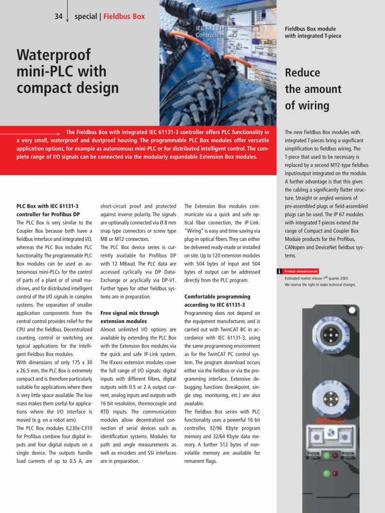
34 special | Fieldbus Box
Waterproof mini-PLC with compact design
PLC Box with IEC 61131-3 controller for Profibus DPThe PLC Box is very similar to the
Coupler Box because both have a
fieldbus interface and integrated I/O,
whereas the PLC Box includes PLC
functionality. The programmable PLC
Box modules can be used as au-
tonomous mini-PLCs for the control
of parts of a plant or of small ma-
chines, and for distributed intelligent
control of the I/O signals in complex
systems. The separation of smaller
application components from the
central control provides relief for the
CPU and the fieldbus. Decentralized
counting, control or switching are
typical applications for the intelli-
gent Fieldbus Box modules.
With dimensions of only 175 x 30
x 26.5 mm, the PLC Box is extremely
compact and is therefore particularly
suitable for applications where there
is very little space available. The low
mass makes them useful for applica-
tions where the I/O interface is
moved (e.g. on a robot arm).
The PLC Box modules IL230x-C310
for Profibus combine four digital in-
puts and four digital outputs on a
single device. The outputs handle
load currents of up to 0.5 A, are
short-circuit proof and protected
against inverse polarity. The signals
are optionally connected via Ø 8 mm
snap type connectors or screw type
M8 or M12 connectors.
The PLC Box device series is cur-
rently available for Profibus DP
with 12 MBaud. The PLC data are
accessed cyclically via DP Data-
Exchange or acyclically via DP-V1.
Further types for other fieldbus sys-
tems are in preparation.
Free signal mix through extension modulesAlmost unlimited I/O options are
available by extending the PLC Box
with the Extension Box modules via
the quick and safe IP-Link system.
The IExxxx extension modules cover
the full range of I/O signals: digital
inputs with different filters, digital
outputs with 0.5 or 2 A output cur-
rent, analog inputs and outputs with
16 bit resolution, thermocouple and
RTD inputs. The communication
modules allow decentralized con-
nection of serial devices such as
identification systems. Modules for
path and angle measurements as
well as encoders and SSI interfaces
are in preparation.
The Fieldbus Box with integrated IEC 61131-3 controller offers PLC functionality ina very small, waterproof and dustproof housing. The programmable PLC Box modules offer versatile application options, for example as autonomous mini-PLC or for distributed intelligent control. The com-plete range of I/O signals can be connected via the modularly expandable Extension Box modules.
Fieldbus Box module with integrated T-piece
Reduce the amount of wiring
The Extension Box modules com-
municate via a quick and safe op-
tical fiber connection, the IP-Link.
“Wiring” is easy and time-saving via
plug-in optical fibers. They can either
be delivered ready-made or installed
on site. Up to 120 extension modules
with 504 bytes of input and 504
bytes of output can be addressed
directly from the PLC program.
Comfortable programming according to IEC 61131-3Programming does not depend on
the equipment manufacturer, and is
carried out with TwinCAT BC in ac-
cordance with IEC 61131-3, using
the same programming environment
as for the TwinCAT PC control sys-
tem. The program download occurs
either via the fieldbus or via the pro-
gramming interface. Extensive de-
bugging functions (breakpoint, sin-
gle step, monitoring, etc.) are also
available.
The Fieldbus Box series with PLC
functionality uses a powerful 16 bit
controller, 32/96 Kbyte program
memory and 32/64 Kbyte data me-
mory. A further 512 bytes of non-
volatile memory are available for
remanent flags.
The new Fieldbus Box modules with
integrated T-pieces bring a significant
simplification to fieldbus wiring. The
T-piece that used to be necessary is
replaced by a second M12-type fieldbus
input/output integrated on the module.
A further advantage is that this gives
the cabling a significantly flatter struc-
ture. Straight or angled versions of
pre-assembled plugs or field-assembled
plugs can be used. The IP 67 modules
with integrated T-pieces extend the
range of Compact and Coupler Box
Module products for the Profibus,
CANopen and DeviceNet fieldbus sys-
tems.
Estimated market release 1st quarter 2003.
We reserve the right to make technical changes.

35 special | Fieldbus Box
The patent for the manufacture of pre-tensioned concrete ties for railroad tracks
was applied for by businessman Leonhard Moll – a pioneer in this field – back
in 1937. If the railroad technology of those days is compared with that of the
modern, high speed world, it is hardly a wonder that the requirements for what
might seem to be such a simple product as a railroad tie have risen enormously.
The portfolio of tie products includes track and points ties for German railroads,
ties for transport services, longitudinal ties for lawn tracks and rail fastening sys-
tems. More than 1,000 railroad ties are produced each day at the factory
in Braunschweig, Germany.
I/O modules with protection class IP 67for more competitive production
Concrete ties – High-tech product?
The challenge of producing concrete ties of high quality and correct dimensions
for an optimum cost in a highly competitive marketplace can only be met with
the help of automated machinery. Leonhard Moll GmbH’s Braunschweig fac-
tory has converted completely to PC-based control technology from Beckhoff, in
accordance with a decision taken by Dieter Oelmann, the man responsible
for control technology. Several Beckhoff Industrial PCs, Control Panels, fieldbus
components in protection class IP 20 and IP 67 and the automation soft-
ware TwinCAT are being used. Leonhard Moll made the decision to use the
“copper version” of Profibus DP at 12 Mbaud for the fieldbus system.
Control functions in today’s automation engineering are moving closer to the sensors and actuators and away from the control cabinet. The fully potted Fieldbus Box modules, in protection classes IP 65/66/67, are ideally suited to this kind of application. The robustand compact I/O modules can be mounted directly on a machine without the need for additional terminal boxes. Leonhard Moll BetonwerkeGmbH & Co. is also taking advantage of this in their production plant for concrete ties. The efficiency and the quality of the concrete ties producedcould be significantly improved with the PC-based control platform TwinCAT and I/O.
In the produc-
tion unit for
railroad ties,
the company
Leonhard Moll
Betonwerke
GmbH & Co.
relies on robust
and compact
fieldbus tech-
nology.

The facility involved is actively engaged in production, so automation is taking
place continuously. This means that relatively simple modules such as material
acceptance are automated and then integrated into the Profibus network.
The production of concrete ties has little connection with concrete pouring as is
done, for instance, for the foundations of a single family house; we are
dealing here with cost-optimized series production of the various tie types. A
distinction is made between different manufacturing processes: in contrast to
“late demolding”, the factory in Braunschweig makes use of “immediate
demolding”.
36 special | Fieldbus Box
As the name might suggest, in this process the concrete tie is taken out of the
mold immediately for further handling, without having to wait for long drying
times in the mold. This makes it possible to work with a limited number of molds,
and these move cyclically through the production process. One disadvantage,
however, is the effect often seen when building sandcastles: If the mixing ratios
are not 100 % correct, the tie can either not be removed from the formwork, or
it collapses. With an average weight of 300 kg, and a length of about 260 cm, the
demands placed on the mixing process and therefore on the control technology
are indeed high.
The man responsible for the
control technology, Dieter
Oelmann, uses Beckhoff
automation components.
More than 1000 railroad ties
are produced every day at the
factory.
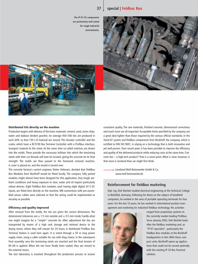
Reinforcement for fieldbus marketing
Dipl. Ing. Dirk Bechtel studied electrical engineering at the Technical College
in Bielefeld, Germany. Following his thesis on the subject of handheld
computers, he worked in the area of portable operating terminals for four
years. For the last 10 years, he has worked in international product man-
agement and marketing for industrial fieldbus technology. His activities
ranged from proprietary systems to
the currently market-leading Profibus.
Since January 2002, Dirk Bechtel looks
after the fieldbus marketing and, as
“IP 67 specialist”, particularly the
Fieldbus Box modules at the Beckhoff
headquarters in Verl. With these com-
pact units, Beckhoff opens up applica-
tions that could not be served optimally
with the existing IP 20 Bus Terminal
solution.
Distributed I/Os directly on the machineProduction begins with delivery of the basic materials: cement, sand, stone chips,
water and diabase (broken granite). An average 450–500 ties are produced in
each shift, so that 150 t of material are moved. The elevator controller and the
scales, which have a BC3100 Bus Terminal Controller with a Profibus interface,
transport material to the mixer. At the same time so-called matrices are drawn
into the molds. These provide the necessary hollows into which the tensioning
steels with their cut threads will later be located, giving the concrete tie its final
strength. The molds are then passed to the formwork removal machine.
A cover is placed on, and the mould is turned over.
The concrete factory’s control engineer, Dieter Oelmann, decided that Fieldbus
Box Modules from Beckhoff would be fitted locally. The compact, fully potted
modules might almost have been designed for this application. Very tough am-
bient conditions and heavy exposure to dust, water and oil require particularly
robust devices. Eight Fieldbus Box modules, each having eight digital 24 V DC
inputs, are fitted here directly on the machine. M8 connections with pre-assem-
bled sensor cables were selected so that the wiring could be implemented as
securely as possible.
Efficiency and quality improvedAfter removal from the molds, the ties are given the correct dimensions. The
dimensional tolerances are ± 1.5 mm outside and ± 0.5 mm inside; hardly what
one might imagine for a “simple” concrete tie. After adjustment the ties are
transported by means of a high rack storage and retrieval device to the
drying stores, where they will remain for 24 hours. A distributed Profibus Bus
Terminal Station is used here again. It is wired through a 50 m long power
supply chain, using a cable suitable for use with drag chains. In the subsequent
final assembly area the tensioning steels are inserted and the final tension of
80 kN is applied. When the ties have finally been sealed, they are moved to
the external stores.
The test laboratory is involved throughout the production process to ensure
37 special | Feldbus Box
consistent quality. The raw materials, finished concrete, dimensional correctness
and much more are all inspected. Acceptable limits specified by the company are
a great deal tighter than those required by the various official standards. In the
TwinCAT system and fieldbus components from Beckhoff, the company, which is
certified to DIN ISO 9001, is relying on a technology that is both innovative and
yet well proven. Over recent years it has been possible to improve the efficiency
and quality of the delivered products while reducing costs at the same time. Con-
crete ties – a high-tech product? That is a moot point. What is clear, however, is
that more is involved than we might first think.
Leonhard Moll Betonwerke GmbH & Co.
www.moll-betonwerke.de
The IP 67 I/O components
are particularly well suited
for rough industrial
environments.
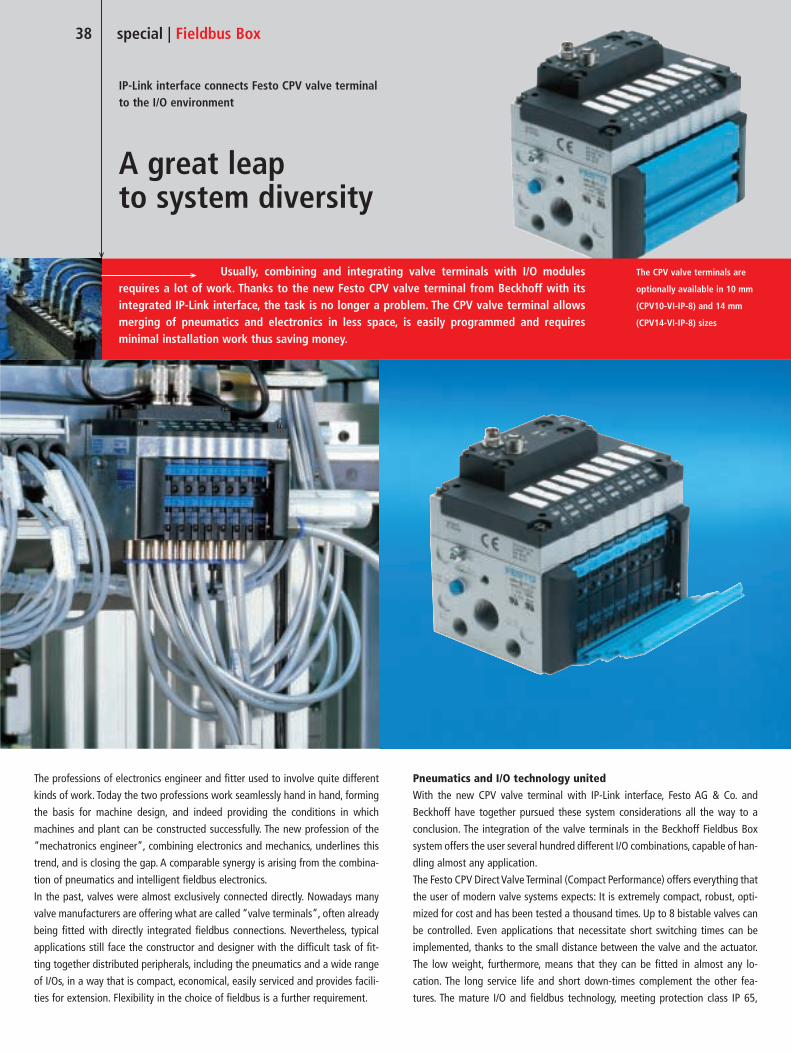
The professions of electronics engineer and fitter used to involve quite different
kinds of work. Today the two professions work seamlessly hand in hand, forming
the basis for machine design, and indeed providing the conditions in which
machines and plant can be constructed successfully. The new profession of the
“mechatronics engineer”, combining electronics and mechanics, underlines this
trend, and is closing the gap. A comparable synergy is arising from the combina-
tion of pneumatics and intelligent fieldbus electronics.
In the past, valves were almost exclusively connected directly. Nowadays many
valve manufacturers are offering what are called “valve terminals”, often already
being fitted with directly integrated fieldbus connections. Nevertheless, typical
applications still face the constructor and designer with the difficult task of fit-
ting together distributed peripherals, including the pneumatics and a wide range
of I/Os, in a way that is compact, economical, easily serviced and provides facili-
ties for extension. Flexibility in the choice of fieldbus is a further requirement.
Pneumatics and I/O technology unitedWith the new CPV valve terminal with IP-Link interface, Festo AG & Co. and
Beckhoff have together pursued these system considerations all the way to a
conclusion. The integration of the valve terminals in the Beckhoff Fieldbus Box
system offers the user several hundred different I/O combinations, capable of han-
dling almost any application.
The Festo CPV Direct Valve Terminal (Compact Performance) offers everything that
the user of modern valve systems expects: It is extremely compact, robust, opti-
mized for cost and has been tested a thousand times. Up to 8 bistable valves can
be controlled. Even applications that necessitate short switching times can be
implemented, thanks to the small distance between the valve and the actuator.
The low weight, furthermore, means that they can be fitted in almost any lo-
cation. The long service life and short down-times complement the other fea-
tures. The mature I/O and fieldbus technology, meeting protection class IP 65,
38 special | Fieldbus Box
Usually, combining and integrating valve terminals with I/O modules requires a lot of work. Thanks to the new Festo CPV valve terminal from Beckhoff with its integrated IP-Link interface, the task is no longer a problem. The CPV valve terminal allowsmerging of pneumatics and electronics in less space, is easily programmed and requires minimal installation work thus saving money.
IP-Link interface connects Festo CPV valve terminal to the I/O environment
A great leap to system diversity
The CPV valve terminals are
optionally available in 10 mm
(CPV10-VI-IP-8) and 14 mm
(CPV14-VI-IP-8) sizes

39 special | Fieldbus Box
Over more than 75 years of the
company’s history, Festo AG &
Co., whose headquarters are in
Esslingen, Germany, has devel-
oped into one of the leading
suppliers of pneumatic compo-
nents and systems. In 176 coun-
tries around the world more
than 10,000 employees look
after more than 300,000 cus-
tomers. 2,800 patents underline
Festo’s claim to be technologi-
cal leaders in the valve terminal
and system sector.
We asked Dipl.-Ing. Rudi Menrad,
Member of the Board,
Sales Management at Festo AG,
Esslingen, to comment:
Every company once had a small
beginning. But in Festo’s case there
are few special points. Both the
owners recognized at an early stage
that pneumatics, which in those
days was a new field of technology,
needed to be made more accessible
to their customers, and formed
Festo Didactic in order to have the
capacity to train their customers.
In contrast to its competitors, the
company has continued to reinvest
its financial yield, not just into fur-
ther development but also into the
52 direct marketing companies that
are now operating around the world.
Our philosophy of presenting our-
selves to customers as complete
suppliers is a further important
point. The focus here is placed on
technology, quality and innovation.
This means that the company must
embody a great deal of knowledge.
Nearly all our field service staff, and
more than 25 % of the entire work-
force are engineers. On top of this,
we invested very early in electronic
data processing, and standardized
the most important systems around
the world.
Emphasis is furthermore placed on
high production depth and compe-
tence in our production depart-
ments. And, last but not least, we
handle 75 % of our customers’
orders on the day they arrive. For
this purpose we have a most effec-
tively functioning logistics center at
Rohrbach, in the Saarland region.
(Reprinted from KEM, dated 08/2002)
“Success factors for the development of a small
mechanical workshop to a world leader in technology”
Dipl.-Ing. Rudi Menrad,
Member of the Board, Sales Management
at Festo AG & Co.
Festo AG & Co.
www.festo.com

40 special | Fieldbus Box
is integrated in the CPV Direct over the IP-Link interface. The direct integration of
IP-Link is thus an extension of the existing valve terminals. This compact interface
contains the IP-Link inputs and outputs, as well as the power supply and down-
stream power feed. The development, which involved a close co-operation
between Festo and Beckhoff, was carried out in response to the demands of
the market. The full extent of the Fieldbus Box range is available to the user:
9 different fieldbusses, 25 different signal types and up to 3 different methods of
connection provide the appropriate solution for almost any application.
Conceived as an I/O system for distributed use, the robust Fieldbus Box modules
can be used directly on the machine or plant in wet, dirty or dusty environments.
With the Coupler Box as a fieldbus station, up to 120 extension modules can be
connected via IP-Link. The IP-Link system is an internal communication connec-
tion, transporting the data for individual devices quickly and reliably over optical
fibers at a transmission rate of 2 Mbit/s.
Full integration in TwinCATThe valve terminal from the CPV Direct series is easily inserted into the Fieldbus
Box system, like an analog Extension Box. It is integrated into the TwinCAT au-
tomation software, and behaves like an analog module with 16 output bits in
compact mode, or with 24 input and output bits in complex mode.
Just like the Extension Boxes, the valve terminals can be located up to 5 m apart.
Both the IP-Link signal and the electrical power supply can conveniently be wired
as a ring. No special configuration is required in the system integration, because
the Coupler Box automatically recognizes the modules. The Coupler Box appears,
from the fieldbus point of view, along with all of the networked extensions, as a
single participating bus device with a corresponding number of I/O signals.
The direct combination of pneumatics with fieldbus and I/O diversity opens pre-
viously undreamed-of benefits and applications to the user. Reduced cost and
wiring radically decreases installation time and other downtime. Distributed
machine units can be implemented quickly and reliably. The wide range of I/O
components ensures high modularity, so permitting cost-optimized plant con-
struction. Because the number of fieldbus nodes decreases, programming and
commissioning are greatly simplified. For all these reasons, the use of the CPV
Direct Valve Terminals with IP-Link interface increases the competitiveness of
machines and of plant.
Typical circuit diagram of the CPV
with IExxxx Extension Box modules
Estimated market release 1st quarter 2003.
Valve terminals obtained from Festo AG & Co.
Fieldbus Box modules obtained from Beckhoff.
We reserve the right to make technical changes.

For further and international sales contacts see: www.beckhoff.com
New Automation Technology
Pentium 4 processor of the latest generation with 533 MHz bus and DDR RAM 7-slot ATX motherboard with up to 220 mm long plug-in cards CD/DVD-ROM, CD-RW or DVD-RAM drive available as floppy drive alternatives Horizontal or vertical installation possible
The Industrial PC C6250 is designed for installation in control cabinets.Together with a Beckhoff Control Panel as operating unit, it offers the idealcombination for a powerful controller. The PC from the highest performanceclass is easily accessible and contains all connections at the front.
Beckhoff Industrial PC | Control Cabinet PC | C6250
The Industrial PC for optimum space utilisation in the control cabinet
The compact Industrial PCwith fast access time High computing power Pentium 4 processor 7-slot ATX motherboard All connections at the front Fast access to the components
| PC1
1-24
E |

Belgium: Industrial PC
controls production
at Leoni cable manu-
facturing plant, page 46
Netherlands: Universal
Corrugated bases
stacking device on
Beckhoff technology,
page 49
Germany: accelab GmbH – Bio-
technology and modern labo-
ratory automation, page 51
PC-based automation for
open-air installations and
greenhouses, page 54
Switzerland: Safety and
protected investment
at Güdel AG, page 56
Beckhoff at the go.auto-
mation.days 2002,
page 59
New representation
in Lower Austria,
page 60
Beckhoff expands its
business in China,
page 66
PC-based control for
PVC doors and windows,
page 67
South Africa:
PC Control for
Volkswagen
production, page 43
Coming soon – Beckhoff
Italy, page 61
New partner sells
products in the Czech
Republic and in Slovakia,
page 61
Beckhoff establishes
subsidiary in Poland,
page 62
Finland: Latest
technologies at the
Tekniikka 2002, page 65
Beckhoff Sweden:
Presence in Scandinavia
strengthened, page 64
Port Elizabeth
A S I A
A U S T R A L I A
A F R I C A
S O U T H A M E R I C A
N O R T H A M E R I C A
Singapore
MinneapolisToronto
Sydney
Sao Paulo
Beijing
Kuala Lumpur
Pune
Bangkok Manila
Shanghai
Verl
Istanbul
Auckland
Seoul
42 worldwide
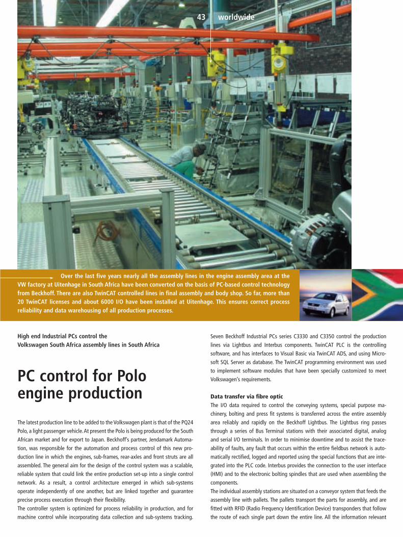
Over the last five years nearly all the assembly lines in the engine assembly area at theVW factory at Uitenhage in South Africa have been converted on the basis of PC-based control technologyfrom Beckhoff. There are also TwinCAT controlled lines in final assembly and body shop. So far, more than20 TwinCAT licenses and about 6000 I/O have been installed at Uitenhage. This ensures correct process reliability and data warehousing of all production processes.
43 worldwide
The latest production line to be added to the Volkswagen plant is that of the PQ24
Polo, a light passenger vehicle.At present the Polo is being produced for the South
African market and for export to Japan. Beckhoff’s partner, Jendamark Automa-
tion, was responsible for the automation and process control of this new pro-
duction line in which the engines, sub-frames, rear-axles and front struts are all
assembled. The general aim for the design of the control system was a scalable,
reliable system that could link the entire production set-up into a single control
network. As a result, a control architecture emerged in which sub-systems
operate independently of one another, but are linked together and guarantee
precise process execution through their flexibility.
The controller system is optimized for process reliability in production, and for
machine control while incorporating data collection and sub-systems tracking.
High end Industrial PCs control the Volkswagen South Africa assembly lines in South Africa
PC control for Polo engine production
Seven Beckhoff Industrial PCs series C3330 and C3350 control the production
lines via Lightbus and Interbus components. TwinCAT PLC is the controlling
software, and has interfaces to Visual Basic via TwinCAT ADS, and using Micro-
soft SQL Server as database. The TwinCAT programming environment was used
to implement software modules that have been specially customized to meet
Volkswagen’s requirements.
Data transfer via fibre opticThe I/O data required to control the conveying systems, special purpose ma-
chinery, bolting and press fit systems is transferred across the entire assembly
area reliably and rapidly on the Beckhoff Lightbus. The Lightbus ring passes
through a series of Bus Terminal stations with their associated digital, analog
and serial I/O terminals. In order to minimise downtime and to assist the trace-
ability of faults, any fault that occurs within the entire fieldbus network is auto-
matically rectified, logged and reported using the special functions that are inte-
grated into the PLC code. Interbus provides the connection to the user interface
(HMI) and to the electronic bolting spindles that are used when assembling the
components.
The individual assembly stations are situated on a conveyor system that feeds the
assembly line with pallets. The pallets transport the parts for assembly, and are
fitted with RFID (Radio Frequency Identification Device) transponders that follow
the route of each single part down the entire line. All the information relevant
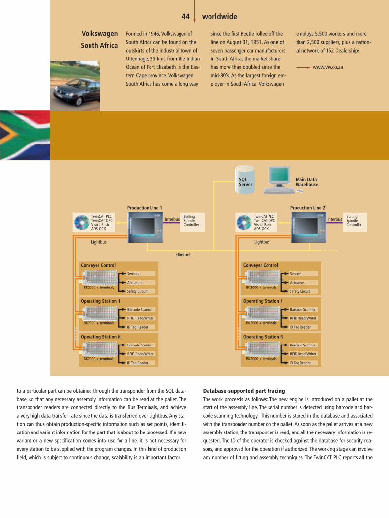
to a particular part can be obtained through the transponder from the SQL data-
base, so that any necessary assembly information can be read at the pallet. The
transponder readers are connected directly to the Bus Terminals, and achieve
a very high data transfer rate since the data is transferred over Lightbus. Any sta-
tion can thus obtain production-specific information such as set points, identifi-
cation and variant information for the part that is about to be processed. If a new
variant or a new specification comes into use for a line, it is not necessary for
every station to be supplied with the program changes. In this kind of production
field, which is subject to continuous change, scalability is an important factor.
Database-supported part tracingThe work proceeds as follows: The new engine is introduced on a pallet at the
start of the assembly line. The serial number is detected using barcode and bar-
code scanning technology. This number is stored in the database and associated
with the transponder number on the pallet. As soon as the pallet arrives at a new
assembly station, the transponder is read, and all the necessary information is re-
quested. The ID of the operator is checked against the database for security rea-
sons, and approved for the operation if authorized. The working stage can involve
any number of fitting and assembly techniques. The TwinCAT PLC reports all the
44 worldwide
Formed in 1946, Volkswagen of
South Africa can be found on the
outskirts of the industrial town of
Uitenhage, 35 kms from the Indian
Ocean of Port Elizabeth in the Eas-
tern Cape province. Volkswagen
South Africa has come a long way
since the first Beetle rolled off the
line on August 31, 1951. As one of
seven passenger car manufacturers
in South Africa, the market share
has more than doubled since the
mid-80’s. As the largest foreign em-
ployer in South Africa, Volkswagen
Volkswagen
South Africa
BoltingSpindleController
Interbus
Conveyer Control
BK2000 + terminals
Sensors
Actuators
Safety Circuit
Operating Station N
BK2000 + terminals
Barcode Scanner
RFID Read/Writer
ID Tag Reader
Operating Station 1
BK2000 + terminals
Barcode Scanner
RFID Read/Writer
ID Tag Reader
Conveyer Control
BK2000 + terminals
Sensors
Actuators
Safety Circuit
Operating Station N
BK2000 + terminals
Barcode Scanner
RFID Read/Writer
ID Tag Reader
Operating Station 1
BK2000 + terminals
Barcode Scanner
RFID Read/Writer
ID Tag Reader
TwinCAT PLCTwinCAT OPCVisual Basic –ADS-OCX
Production Line 1
TwinCAT PLCTwinCAT OPCVisual Basic –ADS-OCX
Production Line 2
Ethernet
SQLServer
Main DataWarehouse
LightbusLightbus
BoltingSpindleController
Interbus
employs 5,500 workers and more
than 2,500 suppliers, plus a nation-
al network of 152 Dealerships.
www.vw.co.za

resulting data to the SQL Server for permanent storage, and is checked for in-
tegrity and validity. Only when the planned stage of manufacture has been com-
pleted does the system allow the part to be transported on to the next station.
At some stations the pallet is supplied with additional sub-components; barcode-
scanning technology is used again here. The serial numbers of these parts are
then associated with the engine, which is the master part, and the transponder
number. This co-ordinates all the information, and permits traceability of the
data from the individual sub components up to the completed assembly.
45 worldwide
Based in Port Elizabeth, Jendamark
Automation is a leading turnkey so-
lution provider to the Automotive,
Tanning, Pharmaceutical, Food and
Beverage and Packaging Industries.
With thirteen years of Turnkey Pro-
jects and Special Purpose Machin-
ery experience, Jendamark is able
to provide production lines to ex-
port orientated customers. They
have become one of the leading
suppliers of PC-based automation
solutions. Their major automotive
customers include Volkswagen,
BMW, ZF Lemforder, Daimler
Chrysler and Ford, Fresenius Kabi.
Lately their involvement has
extended into the fast growing
and competitive exhaust manufac-
turing and catalytic converter
market.
Jendamark’s projecting capability
encompasses conceptual and final
design, manufacture, assembly,
software engineering, commission-
ing, training and after sales service.
As Southern African agents for a
number of international companies,
Jendamark has a successful compo-
nent sales and marketing team with
representatives countrywide. Their
Technical Training facility completes
the circle of service provided by
Jendamark Automation by provid-
ing training courses on all the
products that they resell including
Beckhoff TwinCAT training.
Jendamark Automation was formed
in 1989 by the current managing
director, Gary Klare and is co-
owned by the operations director,
Quinton Uren and the technical di-
rector, Duane Orton. Since its incep-
tion, Jendamark has grown from
2 people in the beginning days, to
over 80 employees today.
www.jendamark.co.za
User interfaces (HMI) are provided at every station in order to assist processing.
They provide the user with instructions for each working step, and ensure that the
correct procedure is followed for each variant being built. The HMI also displays
process results and statistics. If a station detects the ID of a supervisor, the HMI
will provide a supervisory interface to the production line, so that, if necessary,
the system can be halted, or a parts shortage can be recorded in the database.
This may be in order to trigger further action, or may be for report purposes.
The data available on the server permits performance assessments in respect of
downtimes – including their reasons, and the persons responsible – assembly sta-
tistics and complete assembly reports regarding every item built on the line. This
data is made available through the powerful TwinCAT PLC Software, and is pre-
pared and displayed for the relevant station by means of Visual Basic applications.
These applications have interfaces to the database, and permit authorized staff
to manage line operations, performing tasks such as assigning rights to the op-
erating personnel, specifying shift and cycle times, and setting the control pa-
rameters for production.
Wonderware Intouch, linked with TwinCAT via the OPC Server, is used as the SCA-
DA System. The SCADA package provides maintenance staff with an overview of
the active processes on the production line, and also provides access for the ex-
ecution of defined maintenance functions to control the line with the aid of the
easily operated 19 inch built-in IPCs.
Uniform coding standardThe PLC coding is based on the IEC 61131-3 coding languages, as used through-
out the entire Volkswagen concern.Volkswagen’s maintenance staff have now re-
ceived training in the individual programs, so that all the functions relevant for
this system are properly understood. By combining the structured coding, careful
fieldbus layout, safety mechanisms, data collection and distribution, database
connectivity and process reliability in a single system, you start to realize the ca-
pabilities that are presented to you by PC control.
The new PQ24 product line represents a leap in technological quality for Volks-
wagen South Africa, and illustrates the capacity and flexibility of Beckhoff’s dis-
tributed fieldbus systems and PC controller technology.
Jendamark Automation,
South Africa

Until 10 years ago, most mains connection cables were manufactured manually. Since then, the majority ofmanufacturing has been shifted to low-wage countries, where wage costs are more than 17 times lower than those in Europe.Leoni CWA Cable in Hasselt, Belgium, represents an exception. Their production capacity for mains connection cables is still relatively large. This plant can hold its place against the competition because of advanced automation and rising productivity.
A mains connection cable consists of a plug, a cable and an appropriate socket
for connection to a specific device. The plugs may be standardized for particular
countries, or even for groups of countries, but electrical devices – whether toast-
ers, razors, televisions, PCs or washing machines – have connections that are spe-
cific to the make, or even to the particular model, which means that there is a
very large number of different mains connection cables. Automation of the man-
ufacturing process for this essentially simple product calls for a large number of
relatively complex handling operations: The cable must be cut to the correct
length, outer cladding removed and insulation stripped from the conducting
wires, the loose pins, or a bridge with pins, must be fixed to the conducting wires
by soldering or clamping, and the housing must be molded around it in two fur-
ther working steps. This is followed by a number of tests and checks, because an
extension cable must be safe, and may well have to accord with the safety regu-
lations applicable in particular countries.
Higher quality in spite of falling pricesThe drop in prices in the cable manufacture sector of the market has been ex-
treme: Whereas a cable cost 0.50 EUR about 20 years ago (which corresponds to
about 1.50 EUR when converted to today’s prices) the same cable is now sold for
less than 0.30 EUR, although the requirements for quality have risen sharply.
Thanks to ever-increasing automation that is able to hold the price at the same
level while ensuring uniform quality of the highest class, production at Leoni CWA
Cable is still competitive. In co-operation with Multiprox, Beckhoff’s partner in
Belgium, Leoni’s technical management decided in favor of an automation con-
cept based on the software PLC/NC TwinCAT, and for automation components
from Beckhoff. The first production equipment was converted to use Beckhoff
components in March 2000, and the third machine is already being fitted in the
same way at the moment.
Competitive through the latest automation
Industrial PC controls production at Leoni cable manufacturing plant
46 worldwide

Continuous optimization of the machinesThe production site in Hasselt can look back over many years of tradition in au-
tomation. Until 1990, the factory maintained a large internal development de-
partment for the construction of the machines. Nowadays development is carried
out in co-operation with suppliers, while the construction has entirely been hand-
ed over to other companies. The automation concept is developed, and certain
particular adaptations are carried out, by the company’s own engineers. The fac-
tory in Hasselt has 10 production units, which start with the manufacture of a ca-
ble and take it up to the fully processed mains connection cable. Part of the man-
ufacturing work must still be carried out manually for a few types of cable. It is
planned that the machines will systematically be automated further, so that a
dark room production unit will be achieved.
The oldest machines reached the limits of their development capacity two years
ago: The capacity of the PLCs was too small, and not enough I/Os were available.
The expansion that was then on the agenda called for comprehensive moderni-
zation, one reason for which was the fact that the electrical cabling was becom-
ing more and more entangled and difficult to comprehend. At the same time the
number of suppliers for machine parts was reduced.
Less for moreThe decision in favor of TwinCAT as a replacement for the proprietary controllers
was reached on the basis of a comparison of the price/performance ratios. An In-
dustrial PC with a software PLC is cheaper than a conventional PLC offering the
same facilities. Further advantages include the rapid, reliable transfer of data
through optical fiber over the Lightbus system, and the flexibility of the Beckhoff
Bus Terminals. TwinCAT, furthermore, itself offers short cycle times for the trans-
fer of data over the fieldbus, so that a pulse generator on the machine (100 puls-
es in 1.5 s) can be directly read via one input without the need for special count-
47 worldwide
The production at Cable and Wire Assemblies in Hasselt can remain competitive thanks
to more and more powerful automation. The factory in Belgium is the largest producer
of electric razor cables in the world.

er cards. The PC controller is programmed in accordance with the IEC 61131-3
standard. Every machine fitted with TwinCAT has a Beckhoff Control Panel. Op-
eration is easy to understand, so that fault finding on the machine has become
much easier and faster. Downtime is thus reduced to a minimum. The extensive
and flexible possibilities for further expansion are yet another advantage. Expan-
sion of the system with additional fieldbus devices can be done quickly with an
additional PC card.
Integration of axis controlA robot developed by Leoni themselves is planned for the new project. It has two
degrees of freedom – longitudinal and vertical movement. Its purpose is to ac-
cept the mains connection cables that have been prepared in the previous stages
and to apply the pins to a positioning plate. This plate is then pushed into the in-
jection nozzle by means of a conveying system. This allows the molding of the
plug to be integrated into the automatic production process. Because it is neces-
sary for the robot’s movement to be controllable both in height and velocity (fast
movement followed by slow positioning at the precise position), it is not possible
to use linear pneumatic elements here, but only axis controllers with servomo-
tors. The AX2000 servoamplifier and servomotors from the AM2000 series offer-
ing 8 Nm, 3,000 rpm, and having permanent magnet rotors and built-in resolvers
are used.
Leoni have preferred the Beckhoff solution also for the motors, drives and the NC
software necessary on the PCs for control of the robot movement. The TwinCAT
NC PTP software can run on the same Industrial PC (Celeron 700 MHz, 64 MB
SDRAM) as the TwinCAT software PLC, resulting in a machine controller that is
both economical and yet very powerful. The decision was taken to use the Light-
bus again for communication between the PC and the drives, as well as for the
I/Os.
Theoretically, the Beckhoff NC controller can control up to 255 axes with an In-
dustrial PC. If the NC communication is given precedence, above, for example, the
PLC tasks, then the fastest task can be executed within a cycle time of 50 µs. The
IPC used only requires 13 µs to process each axis.
www.multiprox.be
48 worldwide
Leoni CWA Cable was founded in 1964 as a division of
Philips for the manual production of mains connection ca-
bles. In 1990 this division was turned into an independent
company, Cable and Wire Assemblies, and was taken over in
1998 by Leoni, a German group specialized in the produc-
tion of cables and wires, and which can look back over 400
years of company tradition. Leoni operates six factories in
the mains connection cable sector, which is a sub-division of
cable production: Two are in China, and there is one each in
Brazil, Morocco (a subsidiary of CWA), the Czech Republic
and Belgium. The largest production capacity however is
still located in Hasselt, Belgium.
Since the beginning of the 1980s, production in Hasselt has
been automated, and has specialized in the manufacture of
larger series (piece counts of between 5000 and 10000) of
cables with “category 2” connecting plugs. Hasselt is the
largest producer in the world of spiral cables for electric
razors. The production of “power plugs”, in which a 220 V
to 12 V conversion facility is integrated into the plug, will
begin soon. A total of about 1.5 million cables of all types
are produced each week. With 200 employees, the annual
turnover is 37.5 million EUR.
www.leoni.be
Some examples of mains connection cables.
LEONI Cable Assemblies (Belgium) NV
The robot,
controlled by
two Beckhoff
servoamplifiers,
installs the
cables within
the spray lines.

49 worldwide
Cardboard production is generally a mature technology. Gains are only made throughimprovements in logistics, and above all through rapid processing with no malfunctions. One of the mostawkward bottlenecks is represented by the interface between the actual production unit and the stacking and transport facilities.
Universal Corrugated bases stacking device on Beckhoff technology
Software PLC takes center stage
Universal Corrugated B.V. are specialists in delivery appliances and systems for sheet
goods found in the corrugated board and cardboard markets. Universal, whose
headquarters are in Almelo, Netherlands, was founded in 1957, and is a subsi-
diary of the German company of MINDA Industrieanlagen GmbH. Sales manager
Ad Jongmans knows how centrally important his systems are: “If only the tiniest
thing goes wrong in our equipment, the whole production line jams.” Thanks to
a range of innovative developments, and through the use of the TwinCAT software
PLC, Universal have achieved a leading position in their sector, with a market share
of between 10 and 15%.
Stacking the individual sheets of cardboard as they are cut from the roll is not, in it-
self, problematic. The sheets slide up to a stop on a table that is gradually lowered.
In the past, the sheets were temporarily held on the conveyor by hand, and the stack
was removed, at which point the table returned to its original height. At speeds of up
to 400 meters a minute, human intervention is both impossible and undesirable. Uni-
versal have developed a special system in which the rear of the first sheet of a new
stack that is to be formed is held in place by a vacuum strip. The sheets of the new
stack continue to move on at a low velocity, held in place by the vacuum strip mov-
ing along with them. This makes it possible to empty the table that is located behind
them, and to bring it back into position. In order to prepare for the action of the vac-
uum strip, a braking stage is installed before the stacker, which causes the sheets to
lie over one another like roofing tiles.
Determining the exact moment at which the vacuum strip should begin to act pre-
sents the automation engineer with a difficult task. Picking up a sheet too earlyor too
late leads to incorrect job sizes. Because jobs sizes are tending to shrink, chang-
ing the product within a few minutes is now more the rule than the exception.
Up to 250 job changes per shiftThe stacking system represents an important element within the whole produc-
tion line, starting at the cardboard machine itself and finishing in the temporary
stores. So that the job change and the activity of the vacuum strip are properly
synchronized, the first steps are carried out well before the stacker itself. Sensors
are attached to the cutting machine and to the subsequent conveyor to follow
the process. Software engineer Johan Oude Wesselink: “A signal is passed from
the cutting machine to the stacker at every job change. As well as indicating the
time at which the rear of the first sheet from the new order passes the vacuum
strip, dimension data is also transmitted, so that the stop bar is brought to the
correct position at the correct moment.” This information is passed on to the
equipment that transports the stack away to the intermediate stores. No moni-
toring cameras are used in the system. The process is followed by electronics
alone.
Ad Jongmans likes to compare today’s technology with the traditional, manual
procedure: “The docket that used to be given to the cutting machine along with
a job has been replaced by an electronic “docket” that follows the progress of
the job millisecond by millisecond. This electronic production note is entered in
preparation for the work, and passed on to the other devices that do further pro-
cessing at our parent company, MINDA.”

ments all the functions of the “classical” AS-i Master in the form of a normal Bus
Terminal. This has brought a considerable reduction in the amount of cabling.
According to Oude Wesselink, the great advantage of this bus system is the easy
programmability. “The AS-i is inadequate for a large number of security systems,
but the 32 slaves in the traditional version were more than enough for us.”
The control functions are carried out by three Beckhoff C6150 Industrial PCs run-
ning TwinCAT. Each has a Profibus connection to the frequency controllers and
a Lightbus connection to the Bus Terminals in the control cabinet and to the
terminal boxes. The subsidiary AS-i bus is also coupled to the PC controller
through these fieldbus stations. The Industrial PCs are connected to one another
via Ethernet.
Nearly all the stacker’s elements are driven by frequency controlled three-phase
motors. A few items are still pneumatically driven; hydraulic actuators are no
longer in use.
Commissioning and servicingFrom construction through to on-site installation, commissioning and servicing,
the series machines built at the Almelo works are managed by a fixed team of
mechanics, electricians and software engineers. Most after-sales service is pro-
vided remotely, over an (analog) modem connection to the PC-based controllers.
The communication uses PC-Anywhere; an Internet connection is planned for the
future.
Remote servicing is only provided for the first two years following installation.Af-
ter this initial phase, the workers on site are sufficiently familiar with the system
to avoid or to rectify the most frequent malfunctions. The use of the Bus Terminal
system and of self-calibrating frequency controllers means that both the fre-
quency and the duration of down times are very limited.
www.ial.nl
Because of the increasing speed and the reducing size of orders, the number of
job changes is very large. In the most convenient cases, a job takes several min-
utes to pass through, but there are also machines that undergo 250 changes with-
in 8 hours.The job change, including the formation of a more slowly running stack
with the aid of the vacuum strip, takes a few seconds to occur, so that a fast job
change means that a temporary stack is formed and then removed. Error-free
communication within the production line is essential for smooth operation.
From relay to software PLCUntil 1986, this system was controlled by relay technology. The various types of
hardware PLC then followed. Because of the large quantities of data that must
be processed in a very short time, and the ever increasing production speed, Uni-
versal changed to the DOS based S2000 from Beckhoff, one of the first software-
based PLC systems. They were supported in this project by IAL, Beckhoff’s exclu-
sive partner for the Netherlands.
The change to TwinCAT, running under Windows NT, took place five years ago.
This control software is particularly suitable for transferring large quantities of da-
ta. A Control Panel with a touchscreen has taken the place of the traditional mon-
itor. The display was programmed in Visual Basic by Universal’s engineers.
Fieldbus quartet: Profibus, Lightbus, AS-Interface and EthernetData is communicated between the stacker’s Industrial PC and the machines in
front of and behind it through Ethernet carried by optical fibers. All-plastic fibers
are used for shorter links (up to about 30 meters), while “true” fiber optic cable
is used over greater distances. The frequency controllers are operated via Profibus
network, which can also be used to calibrate the frequency controllers. In this way
a new frequency controller installed after a fault is adjusted automatically.
In the meantime, security components have also been integrated into the bus sys-
tem. Universal used the KL6201 AS-i Master Terminal for this purpose. It imple-
50 worldwide
In addition to the downstacker – in
which the table moves downwards
– Universal have also developed a
system in which the conveyor belt
rises slowly (in step with the mate-
rial supply): the upstacker. In this
case the table remains at the same
height. The upstacker allows work
to proceed more quickly, because it
is easier to remove the stack, and
Up- and downstacker
the conveyor belt can return to its
original position in the meantime.
It is, furthermore, possible to form
small packs, and these can then be
assembled into a single large stack
on a separate machine. This tech-
nique is particularly useful when
space is restricted or for products
that tend to warp. Alternate pack-
ages are turned over before stack-
ing in such cases. Visual checks
from time to time are also possible.
www.universal-corrugated.com

The company accelab GmbH based in Kusterdingen, Germany, deals with solutions for accelerating laboratoryprocesses. The motto of the specialists for innovative laboratory automation is the guiding principle “creativity for people – routine for machines”. As a pragmatic implementation of this motto, the scientists, engineers and computer scientists from accelab create customer-specific partial and complete solutions for high sample throughput in the laboratory.
Dr. Martin Winter, managing partner of accelab GmbH, describes the activities of
the company as follows: “Laboratory automation places particular demands on
the classic automation technology that are characterized by the large number
and uniqueness of the processes and products. These individual process compo-
nents are usually essential, i.e. they cannot simply be removed from the process,
and have a high value. For example, tasks in the pharmaceutical, chemical or
biotechnological industry often deal with small product quantities that may
nevertheless represent the world reserves of a substance. Any samples removed
from this quantity can therefore not simply be blown out of the process.”
From engineering concept to laboratory facilityThe activities of the customers require highly flexible plants, combined with high
productivity, as far as the plant supplier accelab is concerned.This is the particular
difficulty. On the one hand, it means very high demands on the hardware, which
has to be very reliable. “For example, in our automation solutions we have
to integrate a lot of functionality in very little space”, said Dipl.-Ing. Frank
Greiner, authorized signatory responsible for system and equipment technology
at accelab. Frank Greiner continued: “On the other hand, sophisticated software
is required. This also results in a special requirements profile for the control
technology. We need high signal throughput, in order to integrate and use the
sensors and actuators appropriately.”
Customers from the pharmaceutical, chemistry and biotechnological industries
use the systems designed and created by accelab for advancing their research
into active substances. This means that a large number of chemical compounds
have to be produced, processed and characterized. The substances are initially
synthesized with different, parallelized techniques. Subsequently, analysis
techniques are used to check the chemical identity of the substances. After
synthesis and purification, the samples need to be prepared, so that the
subsequent tests can be carried out with high throughput. This “High Through-
put Screening” ensures, for example in pharmaceutical research, that several hun-
dred thousand individual chemical substances can be checked for their
efficiency in a defined test procedure. It is thus possible to determine relatively
quickly which chemical substances are potentially interesting and may be suitable
as active ingredients for new drugs. Once an active substance has been devel-
oped, the synthesis conditions have to be optimized in order to minimize the
creation of waste products during large-scale production and to ensure that
the product is as clean as possible. For this task, accelab offers sophisticated
parallelized synthesis robots.
Biotechnology andmodern laboratoryautomation
In the highly productive automation solutions fromaccelab GmbH, Beckhoff Industrial PCs and fieldbusproducts are part of the central nervous system
51 worldwide
Automation
system for
fully automatic
process
optimization
for chemical
reactions.

52 worldwide
Proven components and in-house developmentsSome of the units and peripheral devices used in the accelab automation so-
lutions are in-house developments or joint developments with co-operation
partners, or devices from qualified partner companies. accelab’s know-how is
in system development and system integration, including engineering. One of
the requirements of the accelab plant technology is the capability to handle
toxic or aggressive materials. “Via a central robot control, we are able to operate
flexible structures”, said Frank Greiner. Robot technology is thus a very important
system component in automation solutions. In this respect, the company remains
flexible. Frank Greiner explains: “We don’t use a specific robot. We use the most
appropriate type of robot for each task.”
Flexible control technology for flexible automation solutionsBus Terminals and Industrial PCs from Beckhoff are used in the automation solu-
tions from accelab. The Bus Terminals are available as both digital and analog
terminals to cater for all types of systems. “Since each new accelab automation
system is different from the previous one, the technical system variety and
the so-called fine granularity of the Bus Terminals is very welcome”, said
Dipl.-Ing. Frank Würthner from the Beckhoff branch at Balingen. Even for the
first projects, the flexibility of the Bus Terminals in particular proved to be very
useful. In addition, the Bus Terminal Controllers can be used as mini-PLCs and can
be operated decentralized as local control units. “In terms of communication,
Dr. Martin Winter,
managing partner Dipl.-Ing. (FH) Frank Greiner,
authorized signatory and respon-
sible for system and equipment
technology (automation) at accelab
we recommend either Profibus or Ethernet, depending on the application,”
said Frank Würthner, pointing out that this recommendation was partly deter-
mined by the time requirements and the amount of data to be transferred. Data
throughput will no doubt continue to play an important role in future projects,
i.e. when Control Panels are used in addition to Bus Terminals. “The mail function
used in conjunction with visualization causes the amount of data to be trans-
ferred to be larger,” said Frank Würthner.
The C6110 Industrial PCs from Beckhoff that are used are slot versions with
passive backplane, which is very compact and is therefore ideally suited for this
plant concept, which is also very compact.Apart from TwinCAT, part of the “Work-
flow Manager” laboratory control software developed by accelab also runs on the
Industrial PC. According to the accelab description, the Workflow Manager
is an IT solution for integrating stand-alone laboratory apparatus, robot stations
and analyzers in a unified, programmable laboratory control system.
The high function density and resulting extremely compact configuration of
biotechnological systems means that another feature of the Beckhoff Industrial
PC is particularly advantageous. “All Beckhoff products are specified for tem-
peratures between 0 to 55° C, which means that no additional air-conditioning
devices are required,” said Frank Würthner. While the ambient temperature is not
the critical factor during the operation of the accelab systems, the permanently

53 worldwide
Biotechnological automation
solution from accelab with
turboscara platform
tionality locally”, said Frank Greiner, noting that to this end the Bus Terminal Con-
trollers are addressed via Ethernet (TCP/IP) and thus control complicated sensor
systems such as detectors for phase separation or the superposition of the axis
data in the robot motion control, which represent special measures within the
system control and require local intelligence. The flexibility mentioned also ap-
plies for cases, in which accelab customers require the Profibus to be used as the
system fieldbus. For this too, Beckhoff offers the appropriate intelligent con-
trollers and Bus Couplers.
The system includes gripper changing stations for the handling of the different
vessels and devices by the robot. These grippers can deal with a variety of han-
dling tasks and have various mechanical and technological interfaces at the
change-over flange, for example for compressed air or inert gas. The specific
sensors and actuators in the respective robot gripper are linked via special
plug connectors.
For accelab, flexibility is a very important prerequisite, due to the changing and
varying nature of tasks. According to Frank Greiner, PC control technology and
decentralized control technology are particularly suitable for this purpose.
“Software is also a very important factor for us, which we address through high
reusability of the software components,” said Frank Greiner. In his opinion, this
strategy works very well with Beckhoff products, since this combination makes
it possible to tackle a wide variety of tasks from a common platform.
high performance requirements for the process computer and the resulting
warming of the individual devices have to be considered over-proportionally,
so that the temperature specifications of the Beckhoff devices ensure trouble-free
operation.
Variable connection and installationIn each system, between 100 and 160 solenoid valves have to be controlled,
some of them pneumatic or hydraulic valves. In each system, 200 to 250 digi-
tal input signals and up to 20 analog sensor signals (4 to 20 mA, 0 to 20 mA or
0 to 10 V DC) have to be logged and processed on the input side. To deal with
this, on average up to 5 Bus Terminal Controllers are used in each automation sys-
tem. “The BC9000 Bus Terminal Controllers enable us to also utilize PLC func-
Laboratory facility for carrying
out feasibility studies that feed
into the estimated price offers
www.accelab.de

PC-Control: Mr Kaiser, what were
the main reasons why you chose
Beckhoff technology to automate
the greenhouses and open areas?
Kaiser: The simple and economical
configuration of bus stations, and
also the very small number of nec-
essary spare components. We of
course found the integration of the
optical fiber interface into the Bus
Coupler very appropriate for the
open-air applications. The maximum
channel cost of 15 EUR for a simple
station with 8 digital inputs and 8
digital outputs, including the fibre
optic interface, was then crucial for
the decision in favor of Beckhoff
technology.
PC-Control: You are using the
Beckhoff Lightbus for the open
areas and greenhouses, and you are
also using Ethernet for the building
automation. What have you found
to be the benefits of the continuity
of the TwinCAT system in the con-
figuration and programming?
Kaiser: The same function blocks
can always be used in the controller
for data exchange with all the com-
ponents throughout the entire sys-
tem. This leads to simple programs
which, most importantly, can easily
be understood, and the time saved
as a result is noticeable, particularly
when setting up and fault finding.
Only one interface to the central
engineering PC in the control room
is necessary for remote servicing.
Since 1989 the Beckhoff Lightbus has been used around the world in a very wide variety of applications. Im-munity from interference and high transmission speed mean that fibre optics are ideal for fieldbus systems such as Motion Controltasks with fast cycle times, or for applications that are widely distributed. An example of this is provided by BKN Strobel’s tree nur-series at Holm, north Germany, which have an area of 65,000 m2, making them one of the largest single tree nursery areas in Europe. Altogether 1000 I/Os are linked over a total reach of 3 km. The building automation inside the greenhouses uses Ethernet.
Implementation of BKN Strobel’s concepts set some high targets: Top techno-
logical demands and compact automation units at a reasonable price/perform-
ance ratio – just the job for the engineering office of Kaiser Müller Gerdes GmbH
(KMG) in Schortens, who were charged with the design. In close co-
operation with the firm of Detlev Coldewey, Westerstede, a range of possible
solutions was considered, and a decision was taken in favor of Beckhoff’s tech-
nology. A modern plant, with 60,000 m2 of growing area and a high level of au-
tomation arose from that. BKN Strobel are using a high level technology so that
nothing in the growth and care of the high quality roses and nursery shrubs is
left to chance.
TwinCAT and Beckhoff fieldbus technology for automationFrom Beckhoff’s comprehensive range, the Industrial PC C6250 was chosen as the
hardware platform for the TwinCAT software PLC. The advantages of using the
Beckhoff Lightbus to handle the input and output signals from the open-air
areas and from the greenhouses were convincing:
| Fast transmission of the field signals allows the watering trolleys to be posi-
tioned using standard input and output terminals.
| Pulse sequences < 20 ms need to be evaluated over the optical fiber fieldbus
to execute the positioning.
| The optical fiber bus technology means that it is not necessary to take addi-
tional measures to protect the bus stations against lightning.
| The fieldbus nodes in the optical fiber ring, which has a total length of 3,000
meters, are economical and can be installed quickly. Special glass fibers are
not needed, which means that even the customer can wire them up on site
using appropriate tools.
54 worldwide
PC-based automation for open-air installations and greenhouses
Ethernet inside – Lightbus outside

55 worldwide
The existing Ethernet infrastructure
in the administration area could
also be used for the building au-
tomation, and this yielded consider-
able cost reductions. The same soft-
ware is used for the programming
and for managing the building au-
tomation, and the same standard
components from the Beckhoff Bus
Terminal system are used. The
BC9000 Ethernet controllers in the
different wings of the building can
exchange data between themselves
without using the central PLC con-
troller. The telegram transfer times
that have been achieved, and the
insignificant degree of the in-
creased Ethernet bus loading, con-
firm that our decision in favor of
the Beckhoff solution was the right
one.
PC-Control: Industrial PC C6250
with SCSI Raid Controller techno-
logy: What experience have you
gained of the system as a whole in
terms of reliability and data securi-
ty? What advantages do you see in
the use of Beckhoff Industrial PCs?
Kaiser: One partner when support
or service are needed. Carefully
thought out, solid industrial quality
that can be integrated into a con-
trol cabinet, with no ifs or buts.
The control cabinet constructor, for
instance, finds a familiar connection
technology using spring loaded
terminals for connecting the mains
power. Because both the necessary
operating elements and the con-
nections are located on the front
of the PC, we do not need to use
a pivoting frame. We were im-
pressed by the performance and
the compact dimensions of the
control computer.
Through the UPS that has been
designed for the control computer
and the RAID system for mirroring
the hard disks we have ensured
sufficient security for the programs
and data. Automatic system restart
after a long power failure is also
provided.
The initial configuration of the in-
stallation was designed for only one-
third of the number of data points.
As the implementation proceeded
additional ideas and extensions to
the automation added a large num-
ber of additional field signals. The
power of the PC hardware and of
the Beckhoff Lightbus technology
made it possible to make the final
installation without upgrading
the control platform. We are very
happy with the whole system.
59 Bus Couplers in a 3 km fibre optic ringThe open-air installations and greenhouses are automated with the aid of
BK2010 and BK2020 Bus Couplers, connected to the central C6250 automation
controller via the FC2001 Lightbus PCI master card. At particularly critical loca-
tions, where local functionality must still be ensured during repair or servicing
work on the bus system, the BC2000 intelligent Bus Terminal Controller is used.
This mini PLC undertakes the automation tasks locally, and only transmits its
data for display purposes or for data exchange with the fieldbus system’s master.
The Bus Terminal Controllers are also programmed by the same TwinCAT system
that is used for the central automation tasks. The advantages of a consistent
programming system and uniform tools are exploited here to the full.
OPC – free selection for the display of 8,000 data pointsThe TwinCAT OPC Server offers full selection facilities for the display of the data
points, of which there are about 8000. All of the data points are directly available
to the OPC client. It has access to the bus stations’ process image and also to the
central TwinCAT PLC’s variables area. The data points configured in the TwinCAT
system are available to the OPC server through a symbol file that is generated
when the system is compiled. The following control functions are implemented
for the open-air areas and the greenhouses:
| Shade: Energy screens of fabric laminated with aluminum. Incoming sun-
light can be restricted, and heating to protect from frost is not necessary
for temperatures down to -3° C.
| Watering: Individual time and location patterns for watering trolleys, over-
head irrigation and fertilization
| Ventilation: Supply of fresh air through continuous flap control
| Heating: Heating pipes in the glass houses for winter operation
A weather station records all the weather data required for control, such as tem-
perature, wind direction and strength, the presence and amount of precipitation.
The data acquired in this way is processed by the Beckhoff automation system,
and transferred over the Beckhoff Lightbus to the central TwinCAT software PLC.
Building technology using the ready-made solutions in the TwinCATsystemIn building technology too, a decision has been taken in favour of an open sys-
tem using solutions from Beckhoff. The TwinCAT function blocks and libraries
offer the user ready-made solutions for the integration of standard functions such
as intruder detection, access control, heating, ventilation, air conditioning, light-
ing and sun protection systems. The I/O terminal systems that have already been
used for many years in industry are being applied in building technology as well
with the BC9000 Bus Terminal Controller.
The BC9000 exploits the Ethernet infrastructure present in the building for com-
munication. The design of the Ethernet network and the use of Ethernet switch-
es allows “point-to-point” connections also to be a implemented here with Eth-
ernet’s high transmission rates.
Thomas Kaiser, General Manager of
KMG Umwelttechnik GmbH

Users of drive technology are primarily looking for manufacturers to provide greater safety in their products and well-protected investment, according to participants in a discussion of drive technology with “Aktuelle Technik”.This is no surprise, because the export proportion in this sector is extremely high. Economical service and continuity play a large role here.
56 worldwide
Safety and protected investment
Dipl.-El.-Ing. Heinz Radde,
chief editor “Aktuelle Technik”,
Schlieren (Zürich),
www.aktuelletechnik.ch. (left)
Martin Knuchel from Güdel AG,
Jürg Eggimann from TAS
Engineering AG and Gerhard Meier
from Beckhoff Automation AG.
(left to right)
Radde: Where is the trend in drive technology leading? There are afew new system announcements, such as from Siemens with Simo-tion; Rockwell, Mitsubishi and others also have made announce-ments. Beckhoff are following the PC road. What do users actuallywant nowadays?
Knuchel: From the user’s point of view, there are two trends in automation.
The most important points for the future are:
1. Global functionality must be provided. In other words, we would really like
an open system, so we can use this drive here, that bus there, and so on.
This is incredibly important, because we have different markets (USA, Asia,
Europe), and each has somewhat different needs. We don’t want to keep de-
veloping things from scratch, but want to use the modules again and again.
2. Safety meeting Category 3 must without question become standard through-
out the industry. We must offer drives that meet this requirement, both in
terms of the controller as well as the drive itself. It’s my personal opinion that
the frequency converter is dead. Nowadays, a servo system costs about the
same as a frequency controlled system but has much greater capability and
better properties. A servo system also has the great advantages of the per-
manently excited motor: easier cooling, and greater torque. In highly dynam-
ic situations, PC technology is of enormous advantage. We have programmed
the movement as a 5th order polynomial. That cannot be done with a fixed
system, or at least only with huge difficulty.
Radde: Does “open systems” mean that you want to be able to con-nect together modules from different suppliers even within a singleapplication?
Knuchel: Without question we would like to be able to use a PC based system,
such as is offered by Beckhoff. Under that I might want to have an Intermax
drive, but in the USA I might want to use an Allen Bradley drive. 90 % of our out-
put goes to export. It is necessary to establish conventions. They are on the
horizon, but they are not here yet.
Eggimann: It is also very important for the drive interface to be standardized,
such as is done with SERCOS. The great advantage of the Beckhoff controller is
that all the features of a drive, whether it’s cam plates or geared couplings, are
provided in software form on the PC, rather than in the drive. That’s the only way
to be compatible. Special drive features, such as those of Indramat and Allen
Bradley, are not the same – that is firmware. We can define it by software – the
drive does whatever the PC controller tells it to do.
Knuchel: This is just where we have a great advantage, such as for remote
diagnosis. I can log into a normal PC-based system, where I can use simple re-
mote diagnosis involving little overhead and fast response time, and I can check
the full range of features. I can’t do that if I have different systems, or if the intel-
ligence is located in various sub-systems.
Radde: Do you mean diagnosis via internet or Intranet? Is it reallynecessary to change every single bit in the drive, or isn’t that ratherjust something that it is nice to have?
Eggimann: Nowadays we can inspect and set every single bit in the drive over
a standard modem. For example: The two master front axle transducers that are
fixed to the press are checked every 2 ms to see that they have the same value.
It is possible that as a result of a certain amount of play in the press, the com-
parison of the two press transducers reveals some difference. I might, therefore,
have to increase the tolerance a bit. Nowadays we do that via modem. Or if the
end user exchanges a drive, we load the drive data by modem. We have already
done that.

57 worldwide
Meier: Some are even pulling out, sadly. There may be a world-wide SERCOS stan-
dard, but not everybody is sticking to it.
Knuchel: It works for those who are maintaining the SERCOS standard. It means
we are able to exchange drives nowadays without having to make other modifica-
tions. It must be admitted, unfortunately, that it is the big manufacturers who are
holding things up. We would like to use Allen Bradley drives, but that manufactur-
er uses the SERCOS protocol in accordance with their own standard. Layer 7 is still
“crooked” there.
Eggimann: Nowadays we are also running the soft PLC on PCs from Allen
Bradley, Beckhoff or Siemens, for instance, and it works with no problem. That is
open control technology. It does not mean that you can only incorporate things from
one manufacturer. I need to use what the customer wants, and what makes sense,
and not the things that the manufacturer wants me to use.
Radde: What have Beckhoff got to offer for the future?
Meier: .NET will now provide a big step forward. The operating system makes full
use of Internet technology. And the XML-based features will also find their way
into control technology. An XML file can be used, for instance, to configure the
system manager as early as the project planning stage, not just at the controller.
The XML format also allows the documentation to be included immediately,
without having to write the same thing again on a different system. The full con-
nection to the visualization system is available. If I can say in the variable declara-
tion that this variable is an OPC variable, then I don’t have to declare the same vari-
able again in a visualization section. The integration of .NET will give another pow-
erful push forward. The second level on which we are active is that of small CE-
based controllers, where we can extend the Bus Coupler/Controller through bus
“We will continue to work consistently
with Microsoft technology. .NET will
now provide a big step forward.”
[Gerhard Meier, Beckhoff]
“It is also very important for the
drive interface to be standardized,
such as is done with SERCOS.”
[Jürg Eggimann, TAS Engineering AG]
Knuchel: We do that practically every week all over the world, mostly in the USA
and Mexico. Sometimes we have a second telephone line open, so that we can
say when things are switched on or off. That, of course, is something that has a
big effect on cost.
Radde: So you don’t just use remote diagnosis for display, you con-trol and program as well?
Eggimann: Even program changes that are made here are loaded onto the sys-
tem by remote service and immediately tested with the customer. It is important
for PC-based systems that the HMI (Human Machine Interface) has been inte-
grated at the same time. This is not just a matter of fixing bugs, but of helping
the customer, because the same remote diagnosis allows us to see his interface
screen, and to support him over a second line. It is possible, for example, to cor-
rect mistaken operations, just as if we were standing in front of the machine.
Radde: In which parts of the open system are the suppliers still mostfailing you? What do you miss?
Knuchel: It’s mainly the communication interfaces; either the display system
itself, or from the controller to the display system, or from the controller to the
drive. There are still big differences there, and these swallow a lot of the en-
gineering time. Something still has to be done. The PC-based systems are, of
course, best here, because they can use the standard communication tools that
are available for the Microsoft environment in any part of the world. That has
to be the way of the future. OPC communication, for instance, is a simplification
for the display and visualization system. It is not really suitable for rapid process-
es, but at least it is possible to generate a standard so that data can be exchanged
with a reasonable effort. In the case of drives, however, there is still a lot to do.

58 worldwide
control. This means that we have local, distributed intelligence in the terminal
sector too, for cases where that is valuable and the customer wants it.
Radde: We have touched on the topic of .NET – is that something thatusers are currently concerned with, or are you waiting for it to happen?
Knuchel: No, .NET is not yet a major concern – it has not even been standard-
ized yet.
Meier: That will take until autumn. Three different worlds have to be brought
together: The Vision Basic world and C++ are being brought together in the new
C Sharp platform. There will be a single development tool, with which it will then
be possible to program the entire Microsoft world, where three tools are needed
at present.
Eggimann: We are occupied, peripherally, with the question of transferring
Visual Basic applications to .NET. We are examining the consequences and the
necessary new techniques. We have seen that with Visual Basic a great deal
of what is already used in the office environment can be employed for user in-
terfaces too. This may be databases, or the graphical interfaces, where we are al-
so presently implementing solutions.
Radde: You are relying entirely on Microsoft. That almost sounds likea conspiracy!
Meier: We have been on the market now for over 10 years with PC-based con-
trollers. The first soft PLCs were even based on DOS. We then converted
to Windows NT, then to Windows NT Embedded, Windows 2000 and now XP.
This has not given us any problems. Microsoft can offer this upwards compatibil-
ity. And that means that our investment is secure for a long time.
Eggimann: … and then it is still possible to optimize, so the best can be lever-
aged out of the new computer platform. But basically we must port, and every-
thing runs as it did on the old system. Here, of course, Microsoft carries a great
deal of responsibility towards users, to guarantee this portability. Other operating
systems, OS/2 for instance, have disappeared from the market, and the software
must, to all intents and purposes, be thrown away.
Knuchel: I believe that basing ourselves on worldwide standards is the right
way forward. It takes us further forward, provides simplification and increases the
benefits. We Europeans are masters of new standards, but this time we must
leave it to one side.
Radde: What is your opinion of Ethernet’s continuity?
Eggimann: As far as PCs are concerned, this question has now been defused.
Accessing the data from a sensor from somewhere else has long been a reality
for Beckhoff. From any location I have access via Ethernet through the controller
down to the sensor. This continuity is already available. This is unlike the situa-
tion, for instance, with Profinet, where gateways must be created. The PC does
not need this, because it is itself the gateway.
Knuchel: Yes, and communication with nearby or supervisory installations is al-
so straightforward if we can communicate using standards like Ethernet and
TCP/IP.
Eggimann: So even if it isn’t actually yet real-time capable, I still think this sys-
tem has the best chance for the future. This will be made possible in the future
“We would really like an open
system, so we can use this drive
here, that bus there.” [Martin Knuchel]
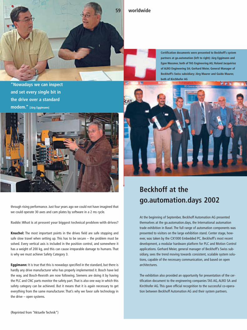
At the beginning of September, Beckhoff Automation AG presented
themselves at the go.automation.days, the International automation
trade exhibition in Basel. The full range of automation components was
presented to visitors on the large exhibition stand. Center stage, how-
ever, was taken by the CX1000 Embedded PC, Beckhoff’s most recent
development, a modular hardware platform for PLC and Motion Control
applications. Gerhard Meier, general manager of Beckhoff’s Swiss sub-
sidiary, sees the trend moving towards consistent, scalable system solu-
tions, capable of the necessary communication, and based on open
architectures.
The exhibition also provided an opportunity for presentation of the cer-
tification document to the engineering companies TAS AG, ALRO SA and
Kirchhofer AG. This gave official recognition to the successful co-opera-
tion between Beckhoff Automation AG and their system partners.
Beckhoff at the go.automation.days 2002
Certification documents were presented to Beckhoff’s system
partners at go.automation (left to right): Jürg Eggimann and
Egon Wassmer, both of TAS Engineering AG; Roland Jacquérioz
of ALRO Engineering SA; Gerhard Meier, General Manager of
Beckhoff’s Swiss subsidiary; Jörg Maurer and Guido Maurer,
both of Kirchhofer AG
“Nowadays we can inspect
and set every single bit in
the drive over a standard
modem.” [Jürg Eggimann]
through rising performance. Just four years ago we could not have imagined that
we could operate 30 axes and cam plates by software in a 2 ms cycle.
Radde: What is at present your biggest technical problem with drives?
Knuchel: The most important points in the drives field are safe stopping and
safe slow travel when setting up. This has to be secure – the problem must be
solved. Every vertical axis is included in the position control, and somewhere it
has a weight of 200 kg, and this can cause irreparable damage to humans. That
is why we must achieve Safety Category 3.
Eggimann: It is true that this is nowadays specified in the standard, but there is
hardly any drive manufacturer who has properly implemented it. Bosch have led
the way, and Bosch-Rexroth are now following. Siemens are doing it by having
the PLC and CNC parts monitor the safety part. That is also one way in which this
safety category can be achieved. But it means that it is again necessary to get
everything from the same manufacturer. That’s why we favor safe technology in
the drive – open systems.
(Reprinted from “Aktuelle Technik”)
59 worldwide

The newly founded Beckhoff subsidiary in Austria,
expanded by adding a branch in Berndorf, south
of Vienna. Beckhoff’s goal is to provide compre-
hensive customer support everywhere in the Aus-
trian region through new sales offices. The new
branch in the Berndorf Innovation Center repre-
sents an important step closer to this target.
Kurt Korinek has been available to customers
as the responsible manager beginning in June
2002. The 45 year-old has many years of experi-
ence as a technician and a sales representative
in automation technology. “I have had a long
connection to Beckhoff. In my professional ca-
reer I have come across Beckhoff products re-
peatedly, as they are used in so many places. I
was fascinated again and again, by the distinc-
tive opportunities offered to customers by the
wide range of products,” explained the new
offered the benefits of Beckhoff’s consistent
company network.
The customer potential in Austria is large, and
the market relatively small. Beckhoff’s strategy
of expanding step-by-step through small,
skilled teams who can react flexibly and quickly
is exactly right for such an environment.
Contact:Beckhoff Automation GmbH
Lower Austria Sales Office
Leobersdorferstr. 42
2560 Berndorf/Austria
Phone: +43 (0) 2672 / 81975-980
Fax: +43 (0) 2672 / 81975-915
e-mail: [email protected]
www.beckhoff.at
60 worldwide
Beckhoff Austria:New representation in Lower Austria
Outside view of the
Berndorf Innovation Center.
sales manager. From the new base, Kurt Korinek
provides customer support to Beckhoff’s cus-
tomers in Vienna and in the regions of Lower
Austria, Steiermark, Burgenland, Kärnten and
East Tyrol. A programmer will in future assist
customers with individual solutions and the
adaptation of Beckhoff products.
Co-operation with the team at Beckhoff’s head-
quarters at Bürs am Vorarlberg is outstanding.
From this head office, Michael Jäger provides
technical support for the customers of the
Lower Austrian office. Kurt Korinek is assisted
with on site project design when necessary by
Armin Pehlivan, managing director of Beckhoff
Austria, or by Klaus Wurm, manager of the
Beckhoff representation in Linz. Contact is also
continuously maintained with the company’s
central offices in Verl, so that customers are
Kurt Korinek, manager of the
new sales office in Lower Austria.

61 worldwide
The course is set forthe future
New partner sells Beckhoff products in the Czech Republic and in Slovakia
In Dyger, Beckhoff has found a strong distribution
partner that is well established in the industrial au-
tomation sector in the central and eastern European
markets. At the same time, this strategic partnership
will strengthen Beckhoff’s activities in the mecha-
nical engineering sector. Dyger’s managing director,
Jiri Holik (35), has been successfully involved in the
distribution of well-known automation brands for
many years.
Dyger has its head office in the Czech city of Brno, a
highly industrialized region of the Czech Republic.
From this location, the sales activities for Slovakia
will also be controlled on behalf of Beckhoff. Three
members of staff will deal with sales and support for
the Beckhoff products and for software applications.
All three have long-standing experience with indus-
trial automation.
For Jiri Holik, the reasons for the co-operation with
Beckhoff are simple: “We want to offer products and
solutions that are competitive worldwide and that
help not only us, but also our customers to be suc-
cessful. In our opinion, Beckhoff meets these require-
ments precisely. With their innovations in industrial
automation, they are one of the leading suppliers
worldwide.”
(left to right) Bernd Pelzer (Export),
Jiri Holik (Dyger) and Managing
Director Hans Beckhoff.
The distribution agreement was signed
at the Hanover Fair in April 2002.
The expansion of Beckhoff’s inter-
national sales network continues.
The new target of the export activi-
ties is Italy with its strong machine
construction and plant engineering
base. In early 2003, Beckhoff will
start its activities by establishing
its own subsidiary. This will make
direct distribution, support and
service available to the Italian in-
dustry. The head office of the new
Beckhoff branch is located in Milan.
Additonal sales offices for cus-
tomer-orientated support are in
preparation. Initially, the new man-
aging director Pierluigi Olivari will
run the show with four further
members of staff.
Contact:Beckhoff Automation S.r.l.
Via E. Majorana, 1
20054 Nova Milanese (MI)
Italy
Phone: +39 (0) 3 62/36 51 64
Fax: +39 (0) 3 62/4 09 90
e-mail: [email protected]
Coming soon:
Beckhoff Italy
Beckhoff is set to expand and concentrate on business activities in the central and eastern European market.During the Hanover Fair in Germany, the company signed an exclusivedistributor contract with Dyger s.r.o. covering the sale of Beckhoffproducts in the Czech Republic and in Slovakia.
The Czech and Slovak markets, with particular em-
phasis on automotive, rubber and plastics, foodstuffs
and chemistry, have significant growth rates.
The partnership with Dyger not only strengthens
Beckhoff’s presence in eastern Europe, but also opti-
mizes the transfer of know-how: Customers benefit
from local services and training. Initial seminar units
are already utilized by well-known international
partners such as Skoda/Volkswagen and Continental.
Contact:Dyger s.r.o.
Purkynova 99
62400 Brno
Czech Republic
Phone: +420 / 5 413 210 04
Fax: +420 / 5 412 492 08
e-mail: [email protected]
www.dyger.cz

“In addition to direct sales of our technologies, beyond the products themselves we offer our customers application support,” says Zbigniew Piatek, Managing Director of Beckhoff Poland, about their sales activities. The establish-ment of the subsidiary in Poland is Beckhoff’s response to the growing demands in this developing market.
Stronger and more active representation
in the booming central and eastern Eu-
ropean market is a particular focus for
Beckhoff. The establishment of its own
subsidiary in Poland will strengthen au-
tomation products sales and end user
support.The Warsaw branch was opened
in July 2002 and is managed by Zbig-
niew Piatek. Piatek (33) has long-stand-
ing experience in the field of industrial
automation, particularly in the areas of
systems, process control and environ-
mental and building services.
The Warsaw industrial market, as the
capital of Poland and thanks to its cen-
tral position, has many applications
which are well suited for Beckhoff tech-
nology. Poland, a country with a popula-
tion of 40 million, aims to join the EU,
which means that consistent economic
growth can be expected.
“Polish entrepreneurs are very open to-
wards new technologies from western
Europe,” says Piatek and continues:
“The expected growth in exports points
to increased interest in automation tech-
nology. Increasingly, demand from mod-
ern companies will orientate itself on
open systems such as PC-based automa-
tion systems from Beckhoff.”
The Poland Beckhoff team plans to ex-
pand their market presence, differentiate
from the competition and establish a
sound basis for automation technology.
Customer focus is very important: In ad-
dition to a close cooperation network
with system integrators, the establish-
ment of sound relationships with end
customers is also planned. “Thanks to
the comprehensive product portfolios,
Beckhoff has much more to offer than
components. Today, customers require
complete solutions, which we supply as
turnkey solutions,” says Piatek.
Further activities of the sales team in
Poland include technical support and
services for international customers who
export their machines and control sys-
62 worldwide
Expansion leads to central and eastern European markets
Beckhoff establishes subsidiary in Poland
tems, equipped with Beckhoff technolo-
gy, to Poland. “Beckhoff’s advantage lies
in the long-standing, proven experience
in the area of PC-based automation,”
says Piatek about the mood in the mar-
ket. He also provides an insight into the
strategy of his team: “We also offer so-
lutions for the more conservative cus-
tomer segment, where hardware PLCs
have been traditionally employed. The
latest innovation from Beckhoff builds
a bridge between the two areas and
combines Industrial PC and PLC in a
single leading edge product.The CX1000
system provides proof that single-func-
tion PLC systems are no longer appro-
priate based on the positive market
feedback. It is becoming apparent that
PC-based control systems in scalable
Bus Terminal format are the future and
that PC-based solutions will generally
dominate the market. With its ‘New Au-
tomation Technology’, Beckhoff offers
highly innovative products and solutions.”
Initially, the team of Managing Director
Zbigniew Piatek will consist of two further
staff for sales and support. The Polish
branch increases the number of Beckhoff
subsidiaries to six: Switzerland, Austria,
Finland, Sweden, Poland, USA plus two
Beckhoff branches in Canada and China.
Furthermore, through cooperation part-
ners, Beckhoff is represented in more
than 30 countries worldwide.
Contact:Beckhoff Automation Sp. z. o.o.
ul. Popularna 56
02-473 Warszawa
Poland
Phone: +48 22/863 95 58
Fax: +48 22/863 95 50
e-mail: [email protected]
Zbigniew Piatek, Managing Director Beckhoff Poland Zbigniew Baginski, Sales Engineer Anna Oltarzewska, Sales & Marketing

The standard contactor with fieldbus connection
For further and international sales contacts see: www.beckhoff.com
New Automation Technology
| BK1
1-09
E |
Beckhoff Bus Terminals | Power Terminal | KL8001
Complete motor control:The Beckhoff Power Terminal
Switching up to 9.9 A True r.m.s. measurement U, I Effective power measurement P Motor diagnostics up to 5.5 kW Operating data via fieldbus Very compact design
This transparency enables preventive maintenance and early detectionof faults for every controller. The Power Terminal is simply installed onthe contactor and connected with the Beckhoff Bus Terminal system viaan adapter. The advantage: low space requirement and communicationoption via fieldbus.
Space is saved and functionality increased: The compact, bus-capableKL8001 Power Terminal from Beckhoff replaces traditional commonmotor protection relays and expands their functionality. The KL8001supplies all main operating data such as motor load, current, voltage,phase fault/failure, overload, underload.

64 worldwide
The automation specialist Beckhoff and the Swedish distributor TR Electronics Sweden AB have a long-standing successful co-operation. The success has resulted in establishing a Beckhoff’s Automation AB subsidiary in Stockholm.The new Swedish subsidiary will facilitate further expansion of Beckhoffs position in the Swedish market.
Presence in Scandinavia strengthened
Beckhoff Sweden
Beginning July 1, 2002, the subsidiary will
take over sales of Beckhoff products from TR
Electronics Sweden AB. TR Electronics and
Beckhoff established a business relationship
in 1990. This was one of Beckhoff’s first offi-
cial foreign agencies. Currently, Beckhoff has
representations in 30 plus countries through
subsidiaries or partner companies.
The new managing director of Beckhoff
Sweden is Björn Forssberg (54), founder of
TR Electronics Sweden. Reflecting on the
past, Forssberg said that the first major
breakthrough occurred in 1993, when Volvo
Torslanda became a customer for the Light-
bus I/O system. Today, Beckhoff sells the
complete range of “New Automation Tech-
nology” products on the Swedish market.
The head office of the Swedish subsidiary
lishing a Swedish subsidiary: “Beckhoff’s
independent representation in Sweden and
also in Finland demonstrates the significance
of the northern European market for the au-
tomation industry. The market is particularly
keen to embrace technological progress.”
Contact:Beckhoff Automation AB
P.O. Box 3032
Djursholmsvägen 50A
18302 Täby
Sweden
Phone: +46 (0) 8 /44 63 000
Fax: +46 (0) 8 /63 00 520
e-mail: [email protected]
is located in Täby, 20 km northwest of
Stockholm. Additional sales offices in
Göteborg and Malmö ensure customer
focus in western and southern Sweden.
Björn Forssberg is supported by an experi-
enced team, consisting of two sales and
support engineers and two admin staff, who
were also taken over from TR Electronics
Sweden. Their knowledge of the Swedish
market and long-standing experience with
Beckhoff products will ensure support of ex-
isting customers and new customers. The
most important industries for the manufac-
turer of PC-based control technology are the
Swedish metal and metal processing indus-
try and the timber processing industry.
Hans Beckhoff, Managing Director of Beck-
hoff, comments on the decision of estab-
(left to right)
Patrick Fredriksson, Sales
Office West, Göteborg,
Bjorn Forssberg, Managing
Director Beckhoff Sweden
and Hakan Brandt, Sales
Office South, Malmö.

65 worldwide
The Beckhoff subsidiary, active in Finland since early 2000, was repre-
sented in Jyväskylä for the second time. The complete range of “New Au-
tomation Technology” products was presented in a 150 m2 booth. The
new CX1000 Embedded PC generated particular interest. Mikko Uuskoski,
managing director of the Finnish subsidiary, said: “The CX1000 is a good
addition to the product family for medium-range control tasks. Its flexible
application options and good price/performance ratio makes it ideally
suited for a large number of applications.” Uuskoski continued: “In Fin-
land, particularly compact machines are developed that require small and
inexpensive control units with open interfaces.”
Implementing new concepts quickly and effectively By now, Beckhoff has achieved a good position in Finland. Mikko Uuskoski
sees the reasons for the continuing success in the strongly technologically
oriented thinking of the Finns: “The Beckhoff control system offers the
latest technologies in hardware and software with open standards. This
enables our customers to implement their concepts quickly and effec-
tively.” The presence at the trade fair reinforced the growing presence
of Beckhoff in Finland. The result after three days was highly success-
ful. “Many visitors have found good solutions for their applications,”
said Matti Korhohnen from the Finnish sales department. The new 18 and
20 inch display sizes for the Control Panels also received a lot of atten-
tion. Visualization tasks often require larger monitors, which are now
also available as industry-variant in protection class IP 65.
Automation in MotionFrom the middle to the end of October, the presentation of Beckhoff tech-
nology was continued with a series of seminars entitled “Automation in
Motion”.The TwinCAT software-based control technology and product in-
novations such as the CX1000, were presented in the towns of Kuopio,
Oulu, Jyväskylä, Tampere, Turku and at Beckhoff’s Finnish head office in
Hyvinkää.
www.beckhoff.fi
Tekniikka 2002, one of the largest automation fairs in Scandinavia, took place September 25-27, in Jyväskylä,central Finland. The Tekniikka is held bi-annually and alternates with the Automaatiopäivät in Helsinki. A total of 160 exhibitorspresented automation components and system solutions from over 1000 companies and 20 countries in five halls.
Beckhoff Finland:Latest technologies at the Tekniikka 2002
The Tekniikka in
Jyväskylä is one of
the largest automation
fairs in Scandinavia.
Mikko Uuskoski,
Managing Director
of Beckhoff Finland,
presented the Embed-
ded PC CX1000 at
the Tekniikka.

C H I N A
BeijingTianjin
Haerbin
Shanghai
Qingdao
WuhanChengdu
KunmingShenzhen
Jinan
Since the “Beckhoff China” representative office was opened in April of 2001, the company’s presence inthe Chinese market has grown dramatically. Forecasted sales for 2002 are on target to double last year’s sales.
To achieve this ambitious goal the num-
ber of workers employed at the Beijing
office has been increased from two to
four. It is planned to open a second of-
fice in Shanghai, one of China’s most im-
portant industrial metropolises, by the
end of 2002.
Beckhoff China’s, wide range of activi-
ties undertaken have provided the basis
for the continuous increase in business
volume:
Trade fairsParticipation in the Industrial Automa-
tion & Control Expo in Shanghai (IAC),
one of the leading exhibitions for
China’s automation industry, between
June 5 and 8, 2002, was very successful,
establishing more than 700 customer
contacts from a wide range of industrial
sectors. Support was provided by Kai
Ristau, the Beckhoff Export Manager,
and by the firm of INSOFT, system inte-
grators and business partners to Beck-
hoff in Shanghai. Between January and
August 2002, the company was present,
in co-operation with partners, at seven
other exhibitions in Jinan, Wuhan, Shen-
yang, Changchun, Beijing, Tianjin and
Qingdao.
PresentationsPresentations and seminars on Beckhoff
fieldbus technology and on PC-based
controllers were held in Beijing,
Hangzhou, Shanghai, Anshan, Pan Zhi-
hua and Kungmin, involving 150 inter-
ested participants. The rapid growth in
the IT industry and the wide acceptance
of the IEC 61131-3 programming stan-
dard are leading to a rising interest in
PC-based control technology in China. A
2-day training course in TwinCAT PLC,
which was repeated this year, increases
the demand for PC-based control tech-
nology, and is an excellent marketing
tool.
Extending the sales networkDeveloping the sales network requires
adapting to the special features of the
Chinese market. The experience of other
foreign firms that have been successful
has been integrated into the growth
strategy. At present, Beckhoff China are
working in co-operation with 10 distrib-
utors in different important cities such
as Beijing, Tianjin, Shanghai, Wuhan,
Shenzhen, Chengdu and Qingdao. A
promising partnership has also been de-
veloped with the automation company
Pepperl+Fuchs, based in Shanghai.
66 worldwide
Beckhoff expandsits business in China
(left to right) The Beckhoff team in China:
Zhenping Chen (Technical Manager),
Qingyan Li (Sales & Marketing Assistant),
Liqiang Liang (Managing Director),
Weilie Liu (Sales).
Below: Industrial Automation &
Control Expo in Shanghai (IAC 2002).

In co-operation with Industrial Software Co., Ltd (INSOFT), a system integratorbased in Shanghai, Beckhoff have implemented a fully automatic production plant for PVC doorsand windows.
67 worldwide
Successful projectsIn the meantime it has been possible to
complete a number of projects success-
fully. In the I/O sector: projects in the au-
tomobile, textile, tire, glass and tobacco
industries, and in the manufacture of
monitoring systems for trucks and
of intelligent control systems for use in
urban infrastructure, building automa-
tion and so forth.
In the PC-based controller sector: door
and window manufacture, remote moni-
toring and control systems for distrib-
uted low-voltage systems.
In addition to this, more and more ma-
chines and production equipment con-
taining Beckhoff components and con-
trol systems are being imported into
China from Europe and the USA in the
wake of the rapidly growing Chinese
economy. An important task therefore
required of the Chinese subsidiary com-
pany is technical support and service for
Beckhoff customers operating interna-
tionally, such as Zimmer AG, Herkules,
Jagenberg, Continental AG, KAMPF and
Dr. Wirth Holding GmbH. Through these
services, Beckhoff China are making an
important contribution to the world-
wide growth of Beckhoff’s automation
business.
PC-based controller technology on produc-tion equipment for PVC doors and windows
Using the TwinCAT ADS interface, INSOFT implemented
a powerful link between the real-time controller pro-
gram (PLC and NC), the HMI, the database for tool and
materials management and the customer logs with their
production data. The TCP/IP network functions integrat-
ed into TwinCAT, and the standard LAN cards fitted in the
PC, support online data exchange between varied plant
components and a network based on the TCP/IP proto-
col. The data necessary for processing a workpiece can
be transferred between the individual plant components
and the network for the production line. Alternatively, in-
formation can be transferred from the PC responsible for
real-time control back to the server for the company
platform, and linked with the ERP system. This provides
a considerable improvement to the management and
use of the production data.
With the aid of Windows NT and TwinCAT, INSOFT were
able to specify the mechanical and electrical design,
to program the real-time controller and the HMI for the
entire production plant, providing a functionality that
embraces everything from the logical PLC control,
through pinpoint multiple axis motion control (TwinCAT
NC PTP) up to the complex synchronized control of mul-
tiple axes (TwinCAT NC I). Since the database functions
are also available for use at the automatic production
line, an installation was created offering coupled net-
work functionality and a high level of automation. From
the economic point of view, the combination and inte-
gration of a production plant with PC systems enables
the plant’s user to achieve a significant improvement in
competitiveness. The TwinCAT controller platform repre-
sents an effective tool for shortening production devel-
opment times and for extending system features.
The performance features required of the system in-
cluded the shortest possible production times in
combination with maximum precision, integration of
the remote diagnosis functionality as well as making
all production data available across the company
network. This was implemented with the TwinCAT
automation software, which integrates PLC, NC (mo-
tion control) and CNC functionality.
In terms of the electromechanical control of the
plant, it had been necessary to consider that, even in
just one machine, more than 40 air cylinders are to
be controlled by sequential logic pressure change
and temperature PID controllers at 5 heating points
in 3 movement axes. In order to implement fully au-
tomatic motion control it was also necessary to use
frequency converters to regulate the speed and po-
sition of various AC motors along the whole produc-
tion line.
Transmission of the process and material data relat-
ing to the current process to the subsequent process
was also automated. When a partly finished work-
piece is passed to a subsequent machine, the new
controller must make use of the received data to
choose the tool and set the appropriate processing
data needed to execute its process. An interface to a
database was also integrated. Its data, gathered
from different machines, is used along with functions
for the automatic transmission of material data for
demonstrations and simulations of the tool move-
ments. It is, additionally, possible for the production
line to be linked to the Internet in accordance with
the customers’ requirements, so that diagnostic da-
ta can be transferred.

Ines Näther, editor of Markt&Technik: Mr. Beckhoff, what growth ratescan be expected over the next five years for operator control &process monitoring systems (O&M systems)?Hans Beckhoff, Managing Director, Beckhoff: Quantitatively, the market will
develop in parallel to the general automation market. However, we expect a shift
within the different device categories and see a trend towards IT-based products,
since they enable the increasing demands on graphics and communication fea-
tures to be met. We feel that this will lead to increased deployment of Industrial
PC types and to over-proportional growth in sales.
How is the market for operator control & process monitoring sys-tems currently developing? What are the trends in technical devel-opment from your point of view?We expect a strong development towards O&M devices with graphic displays,
combined with the utilization of standard operating systems as a basis for this
device category. In addition to the other Microsoft operating systems, Windows
CE will become the standard.
New control concepts in combination with integrated Ethernet net-working have been making their entrance into automation technol-ogy for some time. What effects does this have on O&M?
On one hand, Ethernet replaces proprietary communication systems, therefore
O&M devices need an Ethernet connection. An Industrial PC, in many cases in-
stalled upstream of a classic PLC as a universal O&M and communication device,
has advantages compared with classic O&M technology. Beckhoff has integrated
a complete Pentium PC into the Control Panel series.The result are robust IP 65
O&M devices with displays from 6.5 to 15 inch and a depth of only 30 mm, nat-
urally with integrated Ethernet connection.
For PC-based automation, the “Windows-based Terminal” philosophy enables
new operating principles.The drivers integrated into the Microsoft operating sys-
tem deal with the communication between the application and the remote oper-
ator interface.
What influence does the development of web technologies have on O&M devices? What role will global networking play in future (e-mail, SMS from HMI)?A modern automation system has to support all communication routes and op-
tions of this world. Here too, the PC Control philosophy has a “natural edge” on
the classic, non-IT-oriented control world.
Integrated PLC/MMI solutions have been available for some time, butmost users still use separate units.Is the PLC/MMI a flop?This device class has emerged from the classic PLC world. It does indeed appear
to be the case that users stick with the classic separation of PLC and O&M. For
PC Control automation, the integration of O&M with the control function on a
single hardware platform – the Industrial PC – has become the norm and is seen
by users as a big advantage.
Web technologies had and have significant influence on man-machine communication and aregenerally accepted. The area of operator control and process monitoring is also being shaped by Ethernet technolo-gies. In an interview with Markt&Technik, Hans Beckhoff states his views on current developments.
68 news
The influence of web technology is increasing
Ethernet shapes the function of operator control and process monitoring
“A modern automation
system has to support all
communication routes and
options of this world.”

69 news
Ines Näther is editor of Markt&Technik at
WEKA, publishers of technical journals in
Germany, and responsible for the area of
automation technology.
www.markt-technik.de
More and more users demand unified configuration and program-ming of the complete automation solutions (PLC, MMI, Drive). Howdo you respond to this demand?There is no doubt that there is room for further refinement within automation.
With the TwinCAT automation software, Beckhoff has a comprehensive tool of-
fering a unified programming environment and system configuration for all con-
trol levels.
How can the problem of mouse vs. Industrial PC be solved? Current-ly, there is no technically and ergonomically satisfactory solution.Our customers use touch screens, touch pads, in rare cases trackballs and – in
clean environments – naturally also standard mice. All variants have proven reli-
able in industrial applications. Many applications continue to be operated via the
PC function keys. Located at the bottom of the screen, they enable simple as-
signment of menu functions. Functions that are available at any time are assigned
to so-called PLC menu function keys. These are integrated into the operator in-
terface of the IPC, but are logically assigned directly to the PLC and not to the PC.
Which touch technology and which display technology has thebiggest future in your opinion? How do you see the relationship be-tween touch panel and conventional devices (key and display)? Willone type prevail?We have been using resistive touch technology for years as standard, and our ex-
perience has been very good. Approximately 50-60 % of Beckhoff IPCs are
equipped with this technology.
On 12/13 April 2002, Beckhoff in-
vited its sales staff and distribution
partners to the first International
Sales Meeting at the company
headquarters in Verl, Germany. The
event was held at the attractive
Marienfeld venue, approximately
30 km from Verl. The 108 meeting
participants made for an air of
excitement and enthusiasm.
Managing director Hans Beckhoff
welcomed the delegates from
26 countries and 25 different sub-
sidiaries and partner companies.
The meeting was divided into a
German speaking national part, and
an English speaking international
part. 18 speakers presented on
topics from their respective fields.
The agenda also included the ex-
change of experience and infor-
mation based on Beckhoff’s global
sales activities and exports busi-
ness. The presentation of new
Beckhoff products, in advance of
their official launch at the Hanover
Fair, was a highlight of the meeting.
After the sales meeting, partici-
pants visited the 450 m2 Beckhoff
stand at Hanover.
Beckhoff management intends to
focus on export issues at regular
future ISMs because the foreign
markets are becoming increasingly
significant. They are intended to
intensify and promote the integra-
tion of the global distribution net-
work with the Beckhoff company
headquarters in Germany. The event
was also intended to provide in-
spiration and new ideas regarding
Beckhoff’s international expansion
from 30 to 50 countries and in-
creased exports business. The ISM
created the foundation for better
cooperation and, transnational
dialogue.
Beckhoff integrates global sales at ISM 2002
First International Sales Meeting at Beckhoff

Trade show dates2003
For additional information on our world-
wide subsidiaries and partner companies
trade show schedule please check:
www.beckhoff.com
70 news
Germany
HMI – Hannover Messe
April 07–12, 2003
Hanover
www.hannovermesse.de
Autom@tion 2003
May 20–23, 2003
Stuttgart
Ligna Plus
May 26–30, 2003
Hanover
www.ligna.de
SPS/IPC/DRIVES
November 25–27, 2003
Nuremberg
www.mesago.de/sps
Switzerland
September 02–05, 2003
Ineltec – International trade fair
for Power + Building, Lighting,
Electronics, Basel
www.ineltec.ch
USA
Pacific Design and MFG,
(co located with MD&M
and WestPack)
February 19–21, 2003
Anaheim
National Manufacturing Week
March 01–06, 2003
Chicago
South Pack
April 30 – Mai 01, 2003
Atlanta
AM-Expo
May 06–08, 2003
Greenville
Control Systems Expo
May 20–22, 2003
Boston
Semi-CON
July 16–18, 2003
San Francisco
Assembly show
September 23–25, 2003
Chicago
China
The 5th Intern’l Automation
& Instrument Exhibition
February 26–28, 2003
Chongqing
INTERKAMA China (Process
& Manufacturing Automation
Integrated IT Solutions)
March 18–21, 2003
Shanghai
The 2nd Intern’l Exhibition
on Factory Automation &
Instrumentation
April 01–04, 2003
Shenzhen
The 3rd Intern’l Fieldbus
& Industrial Automation
Exhibition & Technical Exchange
Conference
April 22–25, 2003
Beijing
Austria
Viet 2003
Sept 30 – Oct 3, 2003
Vienna
Italy
MCS Bologna
February 19–21, 2003
Bologna
Intel Milan
May 20–24, 2003
Milan
Poland
Automaticon
April 01–04, 2003
Warsaw
Finland
Automaatio 2003
September 09–11, 2003
Helsinki
Sweden
Svenska Mässan
November 18–21, 2003
Göteborg

Published by:Beckhoff Industrie ElektronikEiserstraße 533415 Verl/GermanyPhone: +49 (0) 52 46 /9 63-0Fax: +49 (0) 52 46 / 9 63 -1 [email protected]
Editorial management:Frank MetznerPhone: +49 (0) 52 46 /9 63-0Fax: +49 (0) 52 46 / 9 63 -1 [email protected]
Picture proof:Cira Moro, Stuttgart,GermanyFesto AG & Co., Esslingen, Germanyindivisual, Everswinkel, GermanyLeoni AG, Nuremberg, GermanySchneider Electric, FranceSMS Demag AG, Düsseldorf, GermanyUniversal Corrugated B.V., Almelo,NetherlandsVeit Mette, Bielefeld, GermanyVolkswagen AG, Wolfsburg, Germany
Graphic Design:www.a3plus.de
Printed by:Gieseking, Bielefeld, Germany
Circulation:10,000
Published 2002 twice a year:(German and English)
PC-Control – The New Automation Technology Magazine
71 news
The innovation prize for architecture
and technology was awarded at the
Light + Building trade fair in Frankfurt,
Germany, in April 2002. The prize had
been announced by the technical jour-
nals AIT and “Intelligente Architektur”
in co-operation with Messe Frankfurt
GmbH. In the “Building technologies”
category, the 1st prize went to the proj-
ect “RaumComputer” – a co-operation
between the companies RaumComput-
er AG from Karlsruhe, Wieland Electric
Stephan Lauer from Wieland Electric GmbH, Professor Dr. Ludger Hovestadt
from RaumComputer AG and Georg Schemmann from Beckhoff received the
innovation prize on behalf of their respective companies.
Light + Building 2002 | Innovation prize for architecture and technology
GmbH from Bamberg and Beckhoff. The
focus was not so much on the products
themselves but on the co-operation be-
tween companies and architects.
The panel, consisting of architects and
representatives from the Light + Build-
ing sponsor associations, explained
their decision as follows: As an innova-
tive building automation system, the
RaumComputer forms an “open and
comprehensive, Internet- and software-
oriented information and communica-
tion platform” for integrated building
services. “Open, because it operates ex-
clusively with standard software. Com-
prehensive, because it expands and in-
tegrates classic building automation
with the issues of security, telecom-
munication, facility management and
e-commerce and combines the building
services across all trade boundaries.”
The RaumComputer applies definitions
at the levels of management, automa-
tion, field and user interfaces. The
communication between the different
levels is based on Ethernet TCP/IP
and XML/XSL. At the field level, the
Beckhoff Bus Terminal system is used,
among others, preferably with Ethernet
controllers.
www.raumcomputer.com

For further and international sales contacts see: www.beckhoff.com
New Automation Technology
| EC1
1-02
E |
Beckhoff PC Control | Embedded PC | CX1000
PLC and Motion Control on a 30 mm DIN Rail Modular control system No fans, no rotating storage media Pentium MMX-compatible 266 MHz processor Master or Slave Fieldbus connection options PLC and Motion Control I/O expansion via IP 20 or IP 67 modules
The modular Industrial PC for mid-range control
data storage on Compact Flash or IBM MicroDrive up to 1 Gbyte I/O expansion via Beckhoff Bus Terminals or Fieldbus Box modules Windows CE.NET or XP Embedded: selectable depending on the application programmable via the Beckhoff TwinCAT automation software
The CX1000 device series from Beckhoff is a 30 mm DIN rail mountable,modular control system based on embedded PC technology: the control system combines PLC, motion control and visualisation optional system interfaces for DVI/USB, COM2/COM3, audio, video


![[Ben10 team] 100 pc errors solved, smart computing reference series [mantesh] e book [4.90 mb] - p hob1a](https://static.fdocuments.in/doc/165x107/54414c37afaf9f62208b4668/ben10-team-100-pc-errors-solved-smart-computing-reference-series-mantesh-e-book-490-mb-p-hob1a.jpg)