Down-flow unit Offer - hosbv.com - Stulz MRD 552.pdf · Down-flow unit Offer Down-flow unit: Brand:...
114
Down-flow unit Offer Down-flow unit: Brand: Stulz Type: MRD 522 GE Capacity: 40 kW (approx) y.o.b. 2000 Pieces: 4 Sizes; 600x850x2000 mm (LxWxH) Electromotor: 4 kW at 1400 RPM
Transcript of Down-flow unit Offer - hosbv.com - Stulz MRD 552.pdf · Down-flow unit Offer Down-flow unit: Brand:...

Down-flow unit Offer
Down-flow unit:
Brand: Stulz
Type: MRD 522 GE
Capacity: 40 kW (approx)
y.o.b. 2000
Pieces: 4
Sizes; 600x850x2000 mm (LxWxH)
Electromotor: 4 kW at 1400 RPM


AIR CONDITIONINGPRECISION A/C UNITS
PLANNING MANUAL
A/C UNITS
INDEX 10PL
Issue 10.00
380-415/3/50MODULAR -LINE DX
© STULZ GmbH, Hamburg
E/1000/10PL/3
Contents Page
Page code 4Model code 5A/C unit diagram/design 7Dimensions/clearances for maintenance 15Performance data
- Design parameters 17- Standard units (MR...) 18
Sound data 26Electrical connected loads 27Fan diagrams 28Supply connections
- Downflow units 40- Upflow units 54- Humidifier 68- Duct connections 69
Raised floor stand 85Diagram on pipe dimensioning 94Alternative ways of combining options 96Tender texts 97Appendix 112

E/1000/10PL/4
Page code
The page code contains the following information
Page no.
Type of manual(PL) planning
Index no. for the "Modular-line" product range (10)
Date of operating instructions (month, year)
Language(D) German(E) English(F) French(S) Spanish(US) US American
E/1000/10PL/3

E/1000/10PL/5
Number of modules
400,460,208,220
Explanation
Unit variants
M R D 33 1 A 400
Product rangeType series
Air discharge directionRefrigerating capacity
Voltage supply
A,G,GE,CW1,2,3,4 or 5
18,26,33,38,46,...D,U
RM
Type of design
Model code
The model code shows the unit variant of your A/C unit and is located under the ratingplate.
The rating plate islocated above orbelow the masterswitch.
Unit design
The A/C units of the "Modular-Line" product range are designed to meet the particularrequirements of customer specifications.Each individual module or unit of the "Modular-Line" product range can be supplied in anumber of variations. The particular attributes of your unit variation can be determinedfrom the model code.

E/1000/10PL/6
Unit variants
This chapter presents the possible unit variations of the "Modular-Line".
Product range: Modular-Line (M)
Type series: Standard (R)
Discharge direction: Downflow (D) Upflow (U)
Cooling capacityper module:
The performance can be increased by assemblingtogether several modules of the same cooling capacity.
Number of modules:
Up to five modules can be joined together, the individualinstallation of the modules is also possible.
= UnitMODULE2 + MODULE
1+
18 kW 26 kW 33 kW 38 kW 46 kW
E/1000/10PL/7
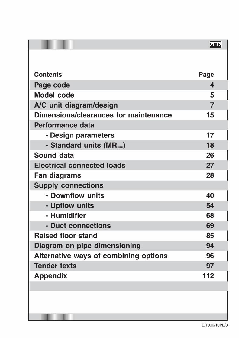
Design of A-unit(using the example of MRD 381 A)
10
15
18
17
1
2
16
3
9
6
5
4
13
7

E/1000/10PL/8
Refrigeration diagram - A-unit
1
Shut-off valveSafety valveNon-return valve (liquid line)Schrader valveTemp./humidity sensorMaster switchSwitch panelPre-filterLow-pressure pressostatHigh-pressure pressostat
11.12.13.14.15.16.17.18.19.20.
3
46 59
710
8
12
13
11
11
14
2019
Low temperature sectionAir section
To externalcondenser
FanMotorCompressorFilter drierSolenoid valve in theliquid lineSight glassCollectorDehumidifier valveExpansion valve
1.2.3.4.5.
6.7.8.9.
10. Evaporator
11
14
14
E/1000/10PL/9
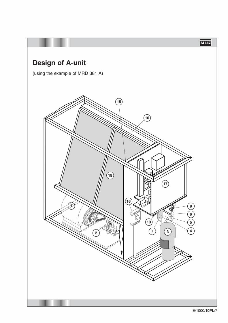
Design of G unit(using the example of MRD 381 G)
1
2
9
12
1514
6
13
3
4
5
8

E/1000/10PL/10
Refrigeration diagram G unit
Schrader valveTemp./humidity sensorMaster switchSwitch panelPre-filterLow-pressure pressostatHigh-pressure pressostat
11.12.13.14.15.16.17.
45
9
Low temperature sectionAir section
FanMotorCompressorFilter drierSight glassCondenserDehumidifier valveExpansion valve
1.2.3.4.5.6.7.8.9.
10.
11
1
7
6
310
1716
8
11
11
EvaporatorShut-off valve
E/1000/10PL/11
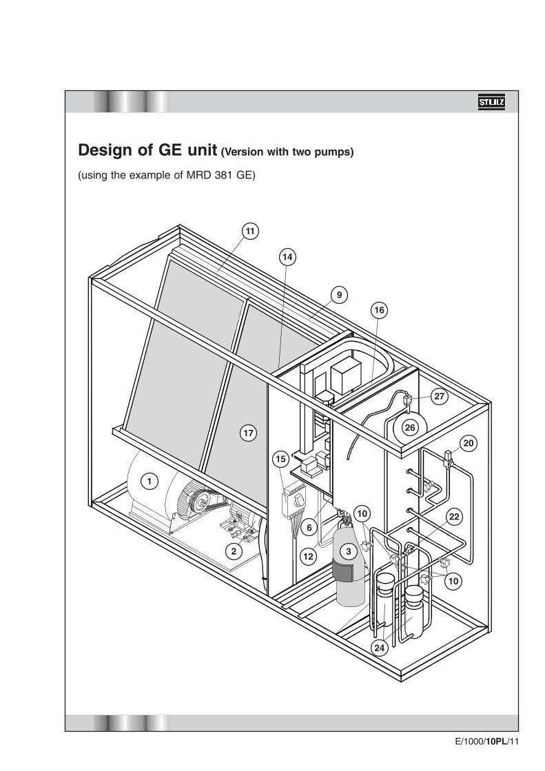
Design of GE unit (Version with two pumps)
(using the example of MRD 381 GE)
2
17
24
10
22
20
10
27
26
1
15
6
312
9
14
11
16
E/1000/10PL/12
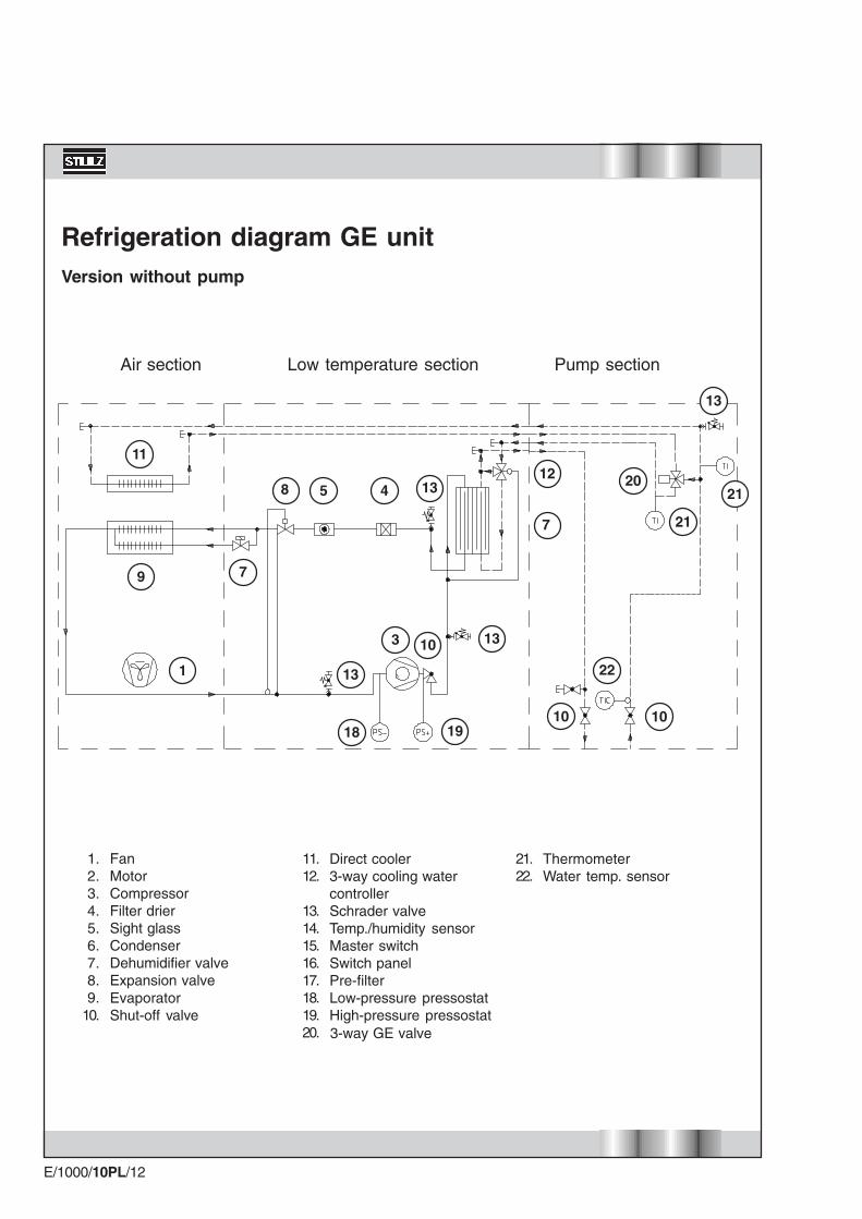
Refrigeration diagram GE unitVersion without pump
Air section Low temperature section Pump section
1
9 7
5 48
7
10
13
3
1918
13
Direct cooler3-way cooling watercontrollerSchrader valveTemp./humidity sensorMaster switchSwitch panelPre-filterLow-pressure pressostatHigh-pressure pressostat
11.12.
13.14.15.16.17.18.19.20.
FanMotorCompressorFilter drierSight glassCondenserDehumidifier valveExpansion valve
1.2.3.4.5.6.7.8.9.
10.
ThermometerWater temp. sensor
21.22.
13
2120
21
1112
22
10 10
13
EvaporatorShut-off valve
3-way GE valve
E/1000/10PL/13
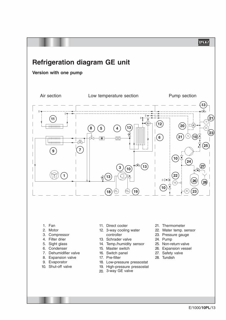
Refrigeration diagram GE unitVersion with one pump
Low temperature sectionAir section Pump section
1
9 7
5 48
6
10
13
3
1918
13
13
20
1112
22
10
10
21
23
24
25
1023
21
Direct cooler3-way cooling watercontrollerSchrader valveTemp./humidity sensorMaster switchSwitch panelPre-filterLow-pressure pressostatHigh-pressure pressostat
11.12.
13.14.15.16.17.18.19.20.
FanMotorCompressorFilter drierSight glassCondenserDehumidifier valveExpansion valve
1.2.3.4.5.6.7.8.9.
10.
ThermometerWater temp. sensorPressure gaugePumpNon-return valveExpansion vesselSafety valveTundish
21.22.23.24.25.26.27.28.
13
EvaporatorShut-off valve
3-way GE valve
26
27
28
E/1000/10PL/14
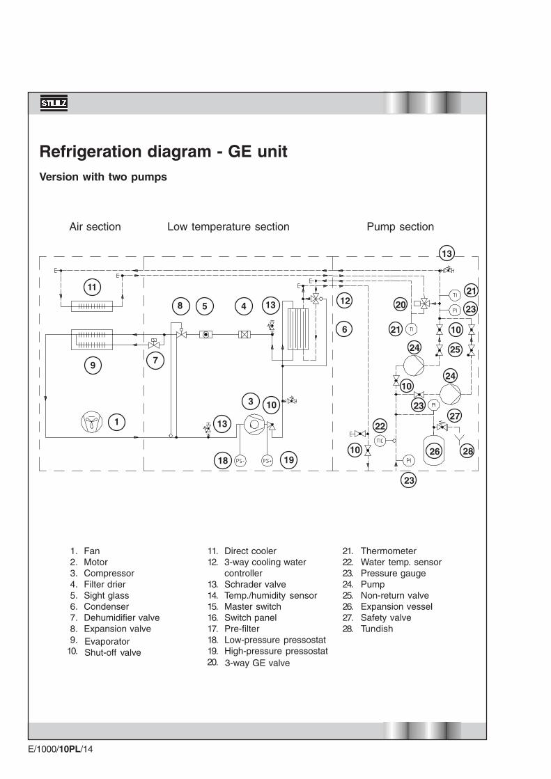
Refrigeration diagram - GE unitVersion with two pumps
Low temperature sectionAir section Pump section
5 48
10
13
3
1918
Direct cooler3-way cooling watercontrollerSchrader valveTemp./humidity sensorMaster switchSwitch panelPre-filterLow-pressure pressostatHigh-pressure pressostat
ThermometerWater temp. sensorPressure gaugePumpNon-return valveExpansion vesselSafety valveTundish
21.22.23.24.25.26.27.28.
11.12.
13.14.15.16.17.18.19.20.
FanMotorCompressorFilter drierSight glassCondenserDehumidifier valveExpansion valve
1.2.3.4.5.6.7.8.9.
10.
9
11
7
1
13 12
6
13
23
26
10
25
10
2327
28
22
24
24
20
21
21
23
10
EvaporatorShut-off valve
3-way GE valve

E/1000/10PL/15
Dimensions
Unit size for A, G, GE units Module width M
Standard down/upflow 181 1130261 1350331 1580381 1800461 2250
Pump section Width P
without or with one pump 450with two pumps 680
Example: Three-module, standard, downflow, GE A/C unit comprising 26 kWmodules with two pumps in the pump section.Model designation in accordance with model code: MRD 783 GE
Dimensions 3 x module width "M" = 3 x 1350 = 4050mm2 x panel thickness = 2 x 25 = 50mm1 x pump section "P" = 1 x 680 = 680mmOverall length of A/C unit 4780mm
M P 252525 M
10
810
747
1950
35
10
25
M M + P
*For dimensions without panels, refer to "duct connections" on page 69
E/1000/10PL/16
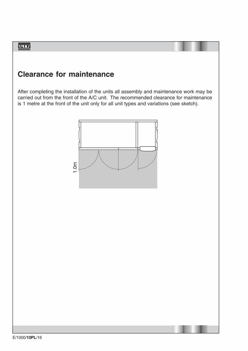
Clearance for maintenance
After completing the installation of the units all assembly and maintenance work may becarried out from the front of the A/C unit. The recommended clearance for maintenanceis 1 metre at the front of the unit only for all unit types and variations (see sketch).
1.0m
E/1000/10PL/17
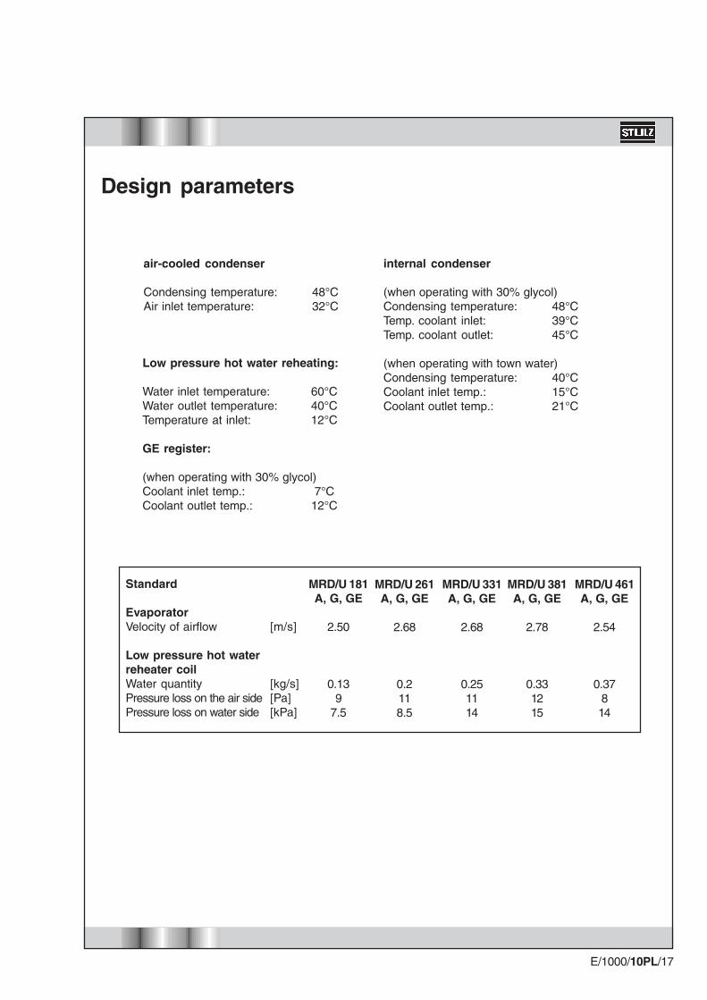
internal condenser
(when operating with 30% glycol)Condensing temperature: 48°CTemp. coolant inlet: 39°CTemp. coolant outlet: 45°C
(when operating with town water)Condensing temperature: 40°CCoolant inlet temp.: 15°CCoolant outlet temp.: 21°C
air-cooled condenser
Condensing temperature: 48°CAir inlet temperature: 32°C
Low pressure hot water reheating:
Water inlet temperature: 60°CWater outlet temperature: 40°CTemperature at inlet: 12°C
GE register:
(when operating with 30% glycol)Coolant inlet temp.: 7°CCoolant outlet temp.: 12°C
Design parameters
Standard
EvaporatorVelocity of airflow
Low pressure hot waterreheater coilWater quantityPressure loss on the air sidePressure loss on water side
[m/s]
[kg/s][Pa][kPa]
MRD/U 181A, G, GE
2.50
0.139
7.5
MRD/U 261A, G, GE
2.68
0.2118.5
MRD/U 331A, G, GE
2.68
0.251114
MRD/U 381A, G, GE
2.78
0.331215
MRD/U 461A, G, GE
2.54
0.37814

E/1000/10PL/18
Evaporator refrigerating capacity (total/sensible)With return air at 22°C/50% r.H.With return air at 24°C/50% r.H.Direct cooler refrigerating capacity (total/sensible)With return air at 22°C/50% r.H.With return air at 24°C/50% r..H.Fan (standard)Type of driveNumber of fansVolume flowExternal pressureMotor nominal output (A,G / GE)Refrigerant circuitRefrigerant quantity R407c (only basic quantity A)Refrigerant quantity R407c (G and GE only)Type of compressorCompressor speedMotor nominal outputCondenser outputCoolant circuit, condenser (G and GE)Water 70%/glycol 30%Coolant mass flowCoolant filling quantityPressure loss, condenser + pipeworkPressure loss, 3-W cooling water controller3-way cooling water controller**Direct free-cooling coil (GE only)Water 70%/glycol 30%Coolant mass flowCoolant filling quantityPressure loss, free-cooling coilPressure loss, free-cooling coil pipingPressure loss, GE 3-way control valveGE 3-way control valveGeneral unit dataLength of unitLength of pump cabinets for GEDepthWeight A,G / GE (only 3 way valve)
Technical data, standard, single-module
* Electrical power consumption of the fan is to include the room load** 2/3-way cooling water control valve as option for G
kWkW
kWkW
m³/hPakW
kgkg
rpmkWkW
kg/sdm³kPakPaDN
kg/sdm³kPakPakPaDN
mmmmmmkg
MRU/D 181A, G / GE
15.3/15.316.2/15.2
15.6/15.618.1/16.1
Belt1
5000702.2
4.02.4
Scroll29003.720.3
0.653.89
253/4''
0.657.4345
143/4''
1180450/680
810340/420
MRU/D 261A, G / GE
23.8/23.825.3/23.5
23.9/23.928.7/25.2
Belt1
750070
3.0 / 4.0
4.02.4
Scroll29005.5
31.2
1.204.62784
3/4''
1.209.42215191''
1400450/680
810380/460
MRU/D 331A, G / GE
29.6/26.531.1/27.1
27.0/27.033.0/28.3
Belt1
900070
2.2 / 3.0
4.02.4
Scroll29007.4
39.5
1.456.22826
1 1/4''
1.4511.1358271''
1630450/680
810410/480
MRU/D 381A, G / GE
36.8/34.139.2/35.1
32.8/32.839.5/36.1
Belt1
1200070
4.0 / 5.5
4.02.4
Scroll29009.6
49.3
1.917.12430
1 1/2''
1.9112.6371018
1 1/4''
1850450/680
810430/520
MRU/D 461A, G / GE
44.1/39.246.7/40.5
44.1/44.153.2/48.3
Belt1
14000704.0
4.02.4
Scroll290012.057.5
2.528.03432
1 1/2''
2.5214.3199
141 1/2''
2300450/680
810450/540

E/1000/10PL/19
Electrical heatingPossible number of heating stagesHeat output in stage 1Heat output in stage 2
Low pressure hot water reheat heatingHeat output 80%
Refrigerant heatingHot gas reheat capacity 40%
Humidifying with steam humidifierHumidifier outputmax. el. power consumption
Humidifying with ultrasonic humidifierHumidifier outputEl. power consumption
Return air filterFilter media in metal frame EU4Pleated filter in cardboard frame EU4Pleated filter in cardboard frame EU5
(Option G) 2-way HP control valve(Option G) 3-way HP control valve
Air-cooled condenserSound level at 5m distance (free field)Sound level at 5m distance (free field)Sound level at 5m distance (free field)Quantity
Technical Data, standard, single-module, options
kWkW
kW
kW
kg/hkW
kg/hkW
DNDN
60 dB (A)50 dB (A)40 dB (A)
MRU/D 181A, G / GE
266
8
4
3-53.6
2.40.12
xstandard
x
1/2"3/4"
KSV021X151AKSV021X251BKSV021X251C
1
MRU/D 261A, G / GE
26/126/12
15
8
8-139.5
3.60.18
xstandard
x
1/2"3/4"
KSV036X251AKSV036X251BKSV036X351C
1
MRU/D 331A, G / GE
26/126/12
18
13
8-139.5
4.80.24
xstandard
x
1/2"1 1/4"
KSV044X251AKSV044X351BKSV044X351C
1
MRU/D 381A, G / GE
26/126/12
24
18
8-139.5
4.80.24
xstandard
x
1/2"1 1/4"
KSV055X251AKSV055X351BKSV055X351C
1
MRU/D 461A, G / GE
26/126/12
31
25
8-139.5
4.80.24
xstandard
x
1/2"1 1/2"
KSV055X251AKSV055X351BKSV055X351C
1

E/1000/10PL/20
Evaporator refrigerating capacity (total/sensible)With return air at 22°C/50% r.H.With return air at 24°C/50% r.H.Direct cooler refrigerating capacity (total/sensible)With return air at 22°C/50% r.H.With return air at 24°C/50% r..H.Fan (standard)Type of driveNumber of fansVolume flowExternal pressureMotor nominal output (A,G / GE)Refrigerant circuitRefrigerant quantity R407c (only basic quantity A)Refrigerant quantity R407c (G and GE only)Type of compressorCompressor speedMotor nominal outputCondenser outputCoolant circuit, condenser (G and GE)Water 70%/glycol 30%Coolant mass flowCoolant filling quantityPressure loss, condenser + pipeworkPressure loss, 3-W cooling water controller3-way cooling water controller**Direct free-cooling coil (GE only)Water 70%/glycol 30%Coolant mass flowCoolant filling quantityPressure loss, free-cooling coilPressure loss, free-cooling coil pipingPressure loss, GE 3-way control valveGE 3-way control valveGeneral unit dataLength of unitLength of pump cabinets for GEDepthWeight A,G / GE (only 3 way valve)
Technical data, standard, dual-module
* Electrical power consumption of the fan is to include the room load** 2/3-way cooling water control valve as option for G
kWkW
kWkW
m³/hPakW
kgkg
rpmkWkW
kg/sdm³kPakPaDN
kg/sdm³kPakPakPaDN
mmmmmmkg
MRU/D 362A, G / GE
30.6/30.632.4/30.4
31.2/31.236.2/32.2
Belt2
10000704.4
8.04.8
Scroll29007.440.6
1.306.09
253/4''
1.309.6346
221''
2310450/680
810680/820
MRU/D 522A, G / GE
47.6/47.650.6/47.0
47.8/47.857.4/50.4
Belt2
1500070
6.0/8.0
8.04.8
Scroll290011.062.4
2.407.62784
3/4''
2.4012.5221529
1 1/4''
2750450/680
810760/920
MRU/D 662A, G / GE
59.2/53.062.2/54.2
54.0/54.066.0/56.6
Belt2
1800070
4.4/6.0
8.04.8
Scroll290014.879.0
2.9013.72826
1 1/4''
2.9018.935942
1 1/4''
3210450/680
810820/1000
MRU/D 762A, G / GE
73.6/68.278.4/70.2
65.6/65.679.0/72.2
Belt2
2400070
8.0/11.0
8.04.8
Scroll290019.298.6
3.8216.13145
1 1/4''
3.8222.0371330
1 1/2''
3650450/680
810860/1060
MRU/D 922A, G / GE
88.2/78.493.4/81.0
88.2/88.2106.4/96.6
Belt2
28000704.0
8.04.8
Scroll290024.0115.0
5.0418.63432
1 1/2''
5.0425.5199
221 1/2''
4550450/680
810900/1120

E/1000/10PL/21
Electrical heatingPossible number of heating stagesHeat output in stage 1 / moduleHeat output in stage 2 / module
Low pressure hot water reheat heatingHeat output 80%
Refrigerant heatingHot gas reheat capacity 40%
Humidifying with steam humidifierHumidifier outputmax. el. power consumption
Humidifying with ultrasonic humidifierHumidifier outputEl. power consumption
Return air filterFilter media in metal frame EU4Pleated filter in cardboard frame EU4Pleated filter in cardboard frame EU5
(Option G) 2-way HP control valve(Option G) 3-way HP control valve
Air-cooled condenserSound level at 5m distance (free field)Sound level at 5m distance (free field)Sound level at 5m distance (free field)Quantity
Technical data, standard, dual-module, options
kWkW
kW
kW
kg/hkW
kg/hkW
DNDN
60 dB (A)50 dB (A)40 dB (A)
MRU/D 362A, G / GE
466
16
8
3-107.2
4.80.24
xstandard
x
1/2"3/4"
KSV021X151AKSV021X251BKSV021X251C
2
MRU/D 522A, G / GE
46/126/12
30
16
8-2619.0
7.20.36
xstandard
x
1/2"3/4"
KSV036X251AKSV036X251BKSV036X351C
2
MRU/D 662A, G / GE
46/126/12
36
26
8-2619.0
9.60.48
xstandard
x
1/2"1 1/4"
KSV044X251AKSV044X351BKSV044X351C
2
MRU/D 762A, G / GE
46/126/12
48
36
8-2619.0
9.60.48
xstandard
x
1/2"1 1/4"
KSV055X251AKSV055X351BKSV055X351C
2
MRU/D 922A, G / GE
46/126/12
62
50
8-2619.0
9.60.48
xstandard
x
1/2"1 1/2"
KSV055X251AKSV055X351BKSV055X351C
2

E/1000/10PL/22
Evaporator refrigerating capacity (total/sensible)With return air at 22°C/50% r.H.With return air at 24°C/50% r.H.Direct cooler refrigerating capacity (total/sensible)With return air at 22°C/50% r.H.With return air at 24°C/50% r..H.Fan (standard)Type of driveNumber of fansVolume flowExternal pressureMotor nominal output (A,G / GE)Refrigerant circuitRefrigerant quantity R407c (only basic quantity A)Refrigerant quantity R407c (G and GE only)Type of compressorCompressor speedMotor nominal outputCondenser outputCoolant circuit, condenser (G and GE)Water 70%/glycol 30%Coolant mass flowCoolant filling quantityPressure loss, condenser + pipeworkPressure loss, 3-W cooling water controller3-way cooling water controller**Direct free-cooling coil (GE only)Water 70%/glycol 30%Coolant mass flowCoolant filling quantityPressure loss, free-cooling coilPressure loss, free-cooling coil pipingPressure loss, GE 3-way control valveGE 3-way control valveGeneral unit dataLength of unitLength of pump cabinets for GEDepthWeight A,G / GE (only 3 way valve)
Technical data, standard, triple-module
* Electrical power consumption of the fan is to include the room load** 2/3-way cooling water control valve as option for G
kWkW
kWkW
m³/hPakW
kgkg
rpmkWkW
kg/sdm³kPakPaDN
kg/sdm³kPakPakPaDN
mmmmmmkg
MRU/D 543A, G / GE
45.9/45.948.6/45.6
46.8/46.854.3/48.3
Belt3
15000706.6
12.07.2
Scroll290011.160.9
1.9510.0
925
3/4''
1.9511.8347
481''
3440450/680
8101020/1220
MRU/D 783A, G / GE
71.4/71.475.9/70.5
71.7/71.786.1/75.6
Belt3
2250070
9.0/12.0
12.07.2
Scroll290016.593.6
3.6015.62784
3/4''
3.6019.2221564
1 1/4''
4100450/680
8101140/1370
MRU/D 993A, G / GE
88.8/79.593.3/81.3
81.0/81.099.0/84.9
Belt3
2700070
6.6/9.0
12.07.2
Scroll290022.2118.5
4.3518.72826
1 1/4''
4.3524.1351039
1 1/2''
4790450/680
8101230/1490
MRU/D 1383A, G / GE
132.3/117.6140.1/121.5
132.3/132.3159.6/144.9
Belt3
4200070
12.0
12.07.2
Scroll290036.0
172.5
7.5619.83432
1 1/2''
7.5630.4199
492''
6800450/680
8101350/1670
MRU/D 1143A, G / GE
110.4/102.3117.6/105.3
98.4/98.4118.5/108.3
Belt3
3600070
12.0/16.5
12.07.2
Scroll290028.8147.9
5.7317.83145
1 1/4''
5.7327.1371666
1 1/2''
5450450/680
8101290/1580

E/1000/10PL/23
Electrical heatingPossible number of heating stagesHeat output in stage 1 / moduleHeat output in stage 2 / module
Low pressure hot water reheat heatingHeat output 80%
Refrigerant heatingHot gas reheat capacity 40%
Humidifying with steam humidifierHumidifier outputmax el. power consumption
Humidifying with ultrasonic humidifierHumidifier outputEl. power consumption
Return air filterFilter media in metal frame EU4Pleated filter in cardboard frame EU4Pleated filter in cardboard frame EU5
(Option G) 2-way HP control valve(Option G) 3-way HP control valve
Air-cooled condenserSound level at 5m distance (free field)Sound level at 5m distance (free field)Sound level at 5m distance (free field)Quantity
Technical data, standard, triple-module, options
kWkW
kW
kW
kg/hkW
kg/hkW
DNDN
60 dB (A)50 dB (A)40 dB (A)
MRU/D 543A, G / GE
666
24
12
3-1510.8
7.20.36
xstandard
x
1/2"3/4"
KSV021X151AKSV021X251BKSV021X251C
3
MRU/D 783A, G / GE
66/126/12
45
24
8-3928.5
10.80.54
xstandard
x
1/2"3/4"
KSV036X251AKSV036X251BKSV036X351C
3
MRU/D 993A, G / GE
66/126/12
54
39
8-3928.5
14.40.72
xstandard
x
1/2"1 1/4"
KSV044X251AKSV044X351BKSV044X351C
3
MRU/D 1143A, G / GE
66/126/12
72
54
8-3928.5
14.40.72
xstandard
x
1/2"1 1/4"
KSV055X251AKSV055X351BKSV055X351C
3
MRU/D 1383A, G / GE
66/126/12
93
75
8-3928.5
14.40.72
xstandard
x
1/2"1 1/2"
KSV055X251AKSV055X351BKSV055X351C
3
E/1000/10PL/24
Evaporator refrigerating capacity (total/sensible)With return air at 22°C/50% r.H.With return air at 24°C/50% r.H.Direct cooler refrigerating capacity (total/sensible)With return air at 22°C/50% r.H.With return air at 24°C/50% r..H.Fan (standard)Type of driveNumber of fansVolume flowExternal pressureMotor nominal output (A,G / GE)Refrigerant circuitRefrigerant quantity R407c (only basic quantity A)Refrigerant quantity R407c (G and GE only)Type of compressorCompressor speedMotor nominal outputCondenser outputCoolant circuit, condenser (G and GE)Water 70%/glycol 30%Coolant mass flowCoolant filling quantityPressure loss, condenser coolant + pipeworkPressure loss, 3-W cooling water controller3-way cooling water controller**Direct free-cooling coil (GE only)Water 70%/glycol 30%Coolant mass flowCoolant filling quantityPressure loss, free-cooling coilPressure loss, free-cooling coil pipingPressure loss, GE 3-way control valveGE 3-way control valveGeneral unit dataLength of unitLength of pump cabinets for GEDepthWeight A,G / GE (only 3 way valve)
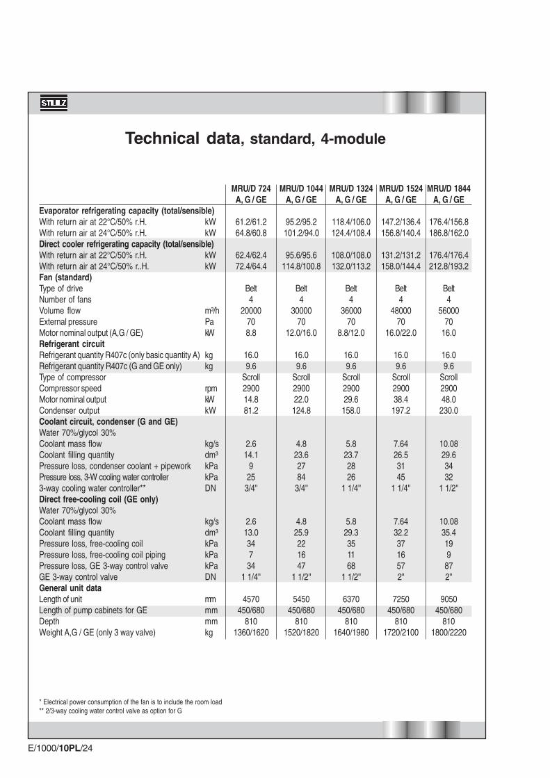
Technical data, standard, 4-module
* Electrical power consumption of the fan is to include the room load** 2/3-way cooling water control valve as option for G
kWkW
kWkW
m³/hPakW
kgkg
rpmkWkW
kg/sdm³kPakPaDN
kg/sdm³kPakPakPaDN
mmmmmmkg
MRU/D 724A, G / GE
61.2/61.264.8/60.8
62.4/62.472.4/64.4
Belt4
20000708.8
16.09.6
Scroll290014.881.2
2.614.1
925
3/4''
2.613.0347
341 1/4''
4570450/680
8101360/1620
MRU/D 1044A, G / GE
95.2/95.2101.2/94.0
95.6/95.6114.8/100.8
Belt4
3000070
12.0/16.0
16.09.6
Scroll290022.0124.8
4.823.62784
3/4''
4.825.9221647
1 1/2''
5450450/680
8101520/1820
MRU/D 1324A, G / GE
118.4/106.0124.4/108.4
108.0/108.0132.0/113.2
Belt4
3600070
8.8/12.0
16.09.6
Scroll290029.6
158.0
5.823.72826
1 1/4''
5.829.3351168
1 1/2''
6370450/680
8101640/1980
MRU/D 1524A, G / GE
147.2/136.4156.8/140.4
131.2/131.2158.0/144.4
Belt4
4800070
16.0/22.0
16.09.6
Scroll290038.4
197.2
7.6426.53145
1 1/4''
7.6432.23716572''
7250450/680
8101720/2100
MRU/D 1844A, G / GE
176.4/156.8186.8/162.0
176.4/176.4212.8/193.2
Belt4
5600070
16.0
16.09.6
Scroll290048.0
230.0
10.0829.63432
1 1/2''
10.0835.4199
872''
9050450/680
8101800/2220
E/1000/10PL/25
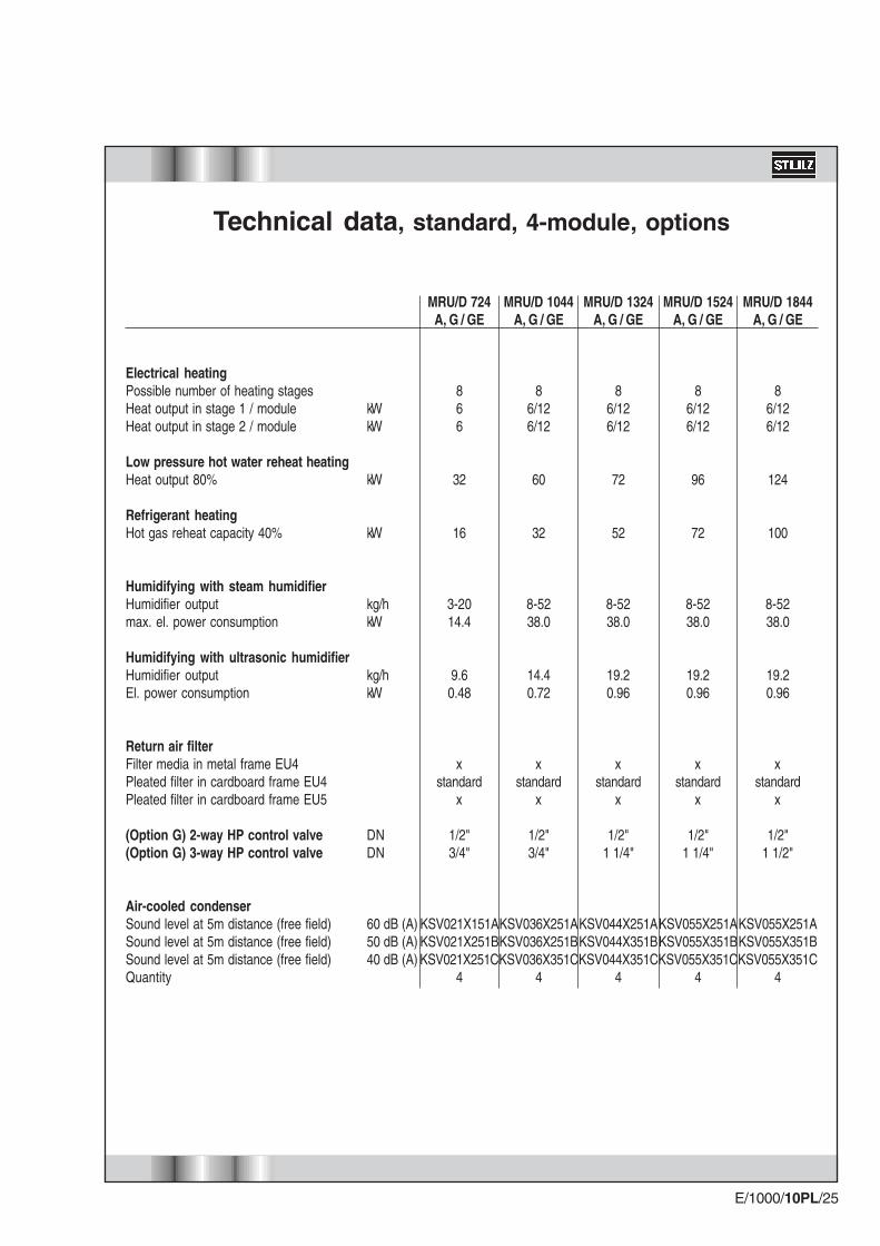
Electrical heatingPossible number of heating stagesHeat output in stage 1 / moduleHeat output in stage 2 / module
Low pressure hot water reheat heatingHeat output 80%
Refrigerant heatingHot gas reheat capacity 40%
Humidifying with steam humidifierHumidifier outputmax. el. power consumption
Humidifying with ultrasonic humidifierHumidifier outputEl. power consumption
Return air filterFilter media in metal frame EU4Pleated filter in cardboard frame EU4Pleated filter in cardboard frame EU5
(Option G) 2-way HP control valve(Option G) 3-way HP control valve
Air-cooled condenserSound level at 5m distance (free field)Sound level at 5m distance (free field)Sound level at 5m distance (free field)Quantity
Technical data, standard, 4-module, options
MRU/D 724A, G / GE
866
32
16
3-2014.4
9.60.48
xstandard
x
1/2"3/4"
KSV021X151AKSV021X251BKSV021X251C
4
MRU/D 1044A, G / GE
86/126/12
60
32
8-5238.0
14.40.72
xstandard
x
1/2"3/4"
KSV036X251AKSV036X251BKSV036X351C
4
MRU/D 1324A, G / GE
86/126/12
72
52
8-5238.0
19.20.96
xstandard
x
1/2"1 1/4"
KSV044X251AKSV044X351BKSV044X351C
4
MRU/D 1524A, G / GE
86/126/12
96
72
8-5238.0
19.20.96
xstandard
x
1/2"1 1/4"
KSV055X251AKSV055X351BKSV055X351C
4
MRU/D 1844A, G / GE
86/126/12
124
100
8-5238.0
19.20.96
xstandard
x
1/2"1 1/2"
KSV055X251AKSV055X351BKSV055X351C
4
kWkW
kW
kW
kg/hkW
kg/hkW
DNDN
60 dB (A)50 dB (A)40 dB (A)

E/1000/10PL/26
Sound data
Sound level in dB (A)
The data are valid at a height of 1m and distance of 2m in front of the unit under free fieldconditions and with nominal data and 70 Pa ext. pressure. The values take into accountthe effects of all installation and design parts contained in the standard unit. The values forupflow units assume an installed discharge duct.The sound levels stated can be further reduced by suitable attenuation measuresdetermined by individual site conditions.
M
2000
1000
Downflow
Unit size
181261331381461
362522662762922
543783993
11431383
7241044132415241844
MRU
5558515755
5861546058
6063566260
6163586361
MRD
5558515755
5861546058
6063566260
6163586361
M
2000
1000
Upflow

E/1000/10PL/27
Electrical connected loadsat 380-415 V / 3Ph / 50 Hz
A/C units with Ultrasonic humidifier are to be treated as A/C units without humidifier due to their lowpower consumption.
Key: Fan Compressor El. heater Steam humidifier
A
A
A
A
A
A
A
A
A
A
6 kW
2 x 6 kW
12 kW
2 x 12 kW
3 - 5 kg/h
8 - 13 kg/h
Equipment MRU/D181
A/G/GE
6.1
15.0
23.7
22.5
8.7
17.3
17.3
-
7.5
-
MRU/D261
A/G/GE
7.6/10.0
21.1/23.5
38.4/40.8
39.1/41.5
8.7
17.3
17.3
34.6
7.5
18.0
MRU/D331
A/G/GE
6.1/7.6
23.2/24.7
40.5/42.0
41.2/42.7
8.7
17.3
17.3
34.6
7.5
18.0
MRU/D381
A/G/GE
10.0/12.9
30.6/33.5
47.9/50.8
48.6/51.5
8.7
17.3
17.3
34.6
7.5
18.0
MRU/D461
A/G/GE
10.0
37.0
54.3
55.0
8.7
17.3
17.3
34.6
7.5
18.0
Steam humidifier
Electric reheaters

E/1000/10PL/28
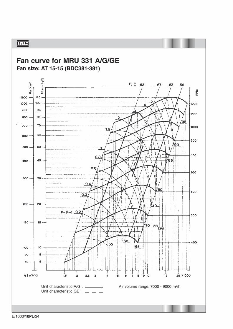
Fan curveDesign example
By means of this example it is explained how the fan speed andpower requirement at the shaft are determined from the fan curvefor a MRU 331 A A/C unit.
Given: (A) Air volume 8000 m3/h(B) p external 70 Pa
Required: (D) Pressure drop of the unit(E) Total pressure drop(F) Fan speed(G) Power requirement at the shaft
PROCEDURE:
Search for the appropriate fan curve for MRU-331 (Page 34).Establish the intersection point (C) of the air volume (A) and theunit characteristics:
determined value (D) = 400 Pa
Add the pressure drop of the unit (D) and the external pressure(B):
(D)+(B)= (E)
determined value (E): 400+70=470 Pa
The operating point (H) is at the intersection point of air volume (A)8000 m3/h and the total pressure drop (E) 470 Pa.
Read off the fan speed (F): 830 rpm
Read off the power requirement at the shaft (G): 1.7 kW
E/1000/10PL/29
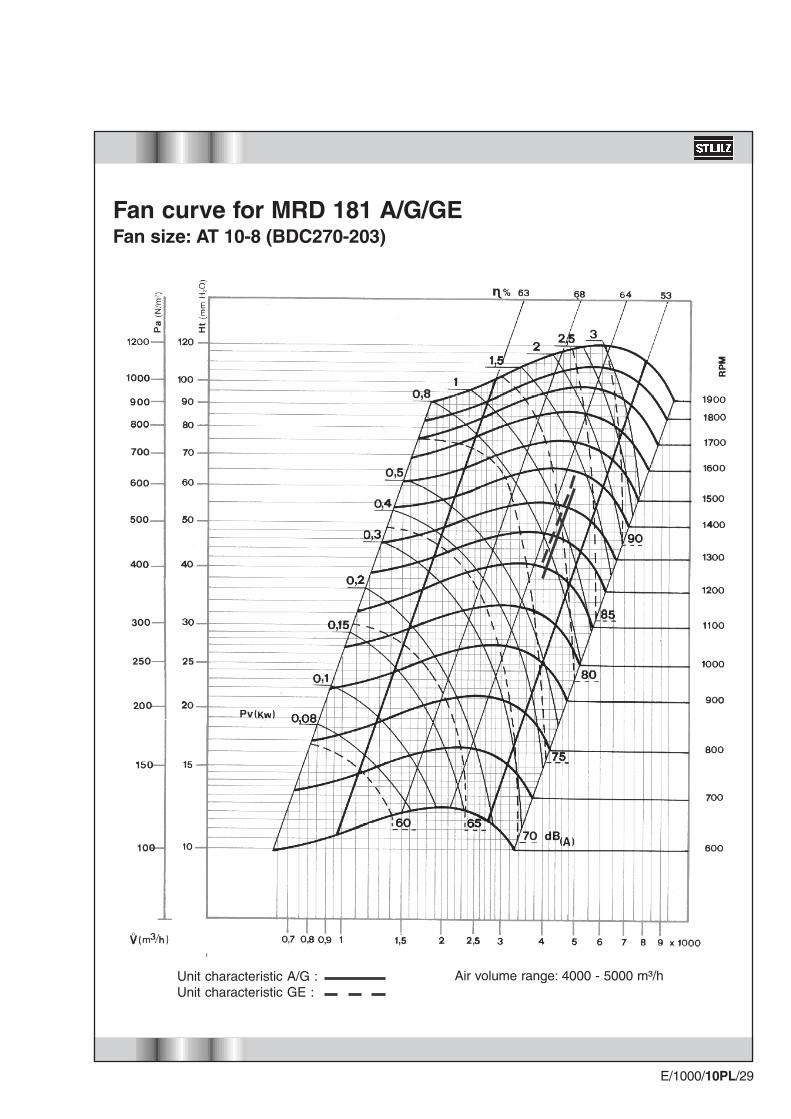
Fan curve for MRD 181 A/G/GEFan size: AT 10-8 (BDC270-203)
Unit characteristic A/G :Unit characteristic GE :
Air volume range: 4000 - 5000 m³/h

E/1000/10PL/30
Fan curve for MRU 181 A/G/GEFan size: AT 10-8 (BDC270-203)
Air volume range: 4000 - 5000 m³/hUnit characteristic A/G :Unit characteristic GE :
E/1000/10PL/31
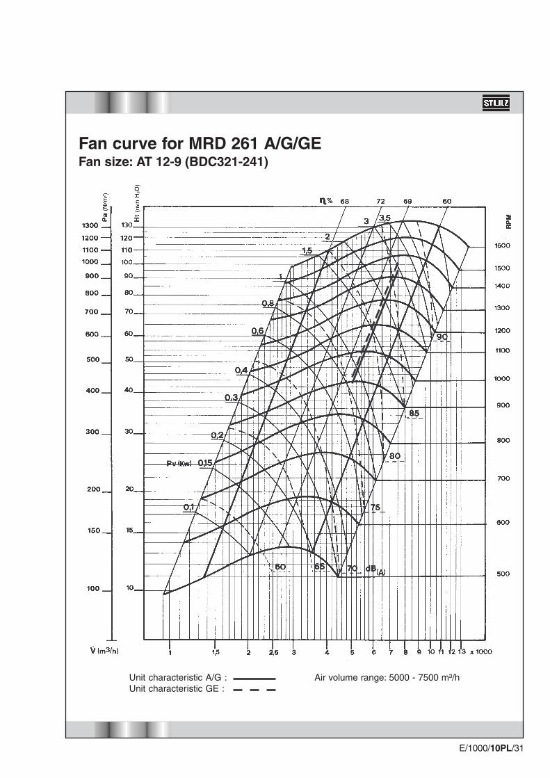
Fan curve for MRD 261 A/G/GEFan size: AT 12-9 (BDC321-241)
Air volume range: 5000 - 7500 m³/hUnit characteristic A/G :Unit characteristic GE :

E/1000/10PL/32
Fan curve for MRU 261 A/G/GEFan size: AT 12-9 (BDC321-241)
Air volume range: 5000 - 7500 m³/hUnit characteristic A/G :Unit characteristic GE :

E/1000/10PL/33
Fan curve for MRD 331 A/G/GEFan size: AT 15-15 (BDC381-381)
Air volume range: 7000 - 9000 m³/hUnit characteristic A/G :Unit characteristic GE :
E/1000/10PL/34
Fan curve for MRU 331 A/G/GEFan size: AT 15-15 (BDC381-381)
Air volume range: 7000 - 9000 m³/hUnit characteristic A/G :Unit characteristic GE :

E/1000/10PL/35
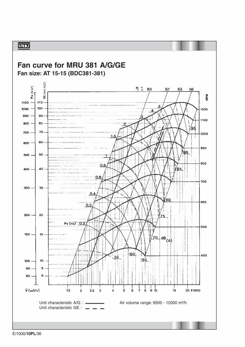
Fan curve for MRD 381 A/G/GEFan size: AT 15-15 (BDC381-381)
Air volume range: 9500 - 12000 m³/hUnit characteristic A/G :Unit characteristic GE :
E/1000/10PL/36
Fan curve for MRU 381 A/G/GEFan size: AT 15-15 (BDC381-381)
Air volume range: 9500 - 12000 m³/hUnit characteristic A/G :Unit characteristic GE :
E/1000/10PL/37
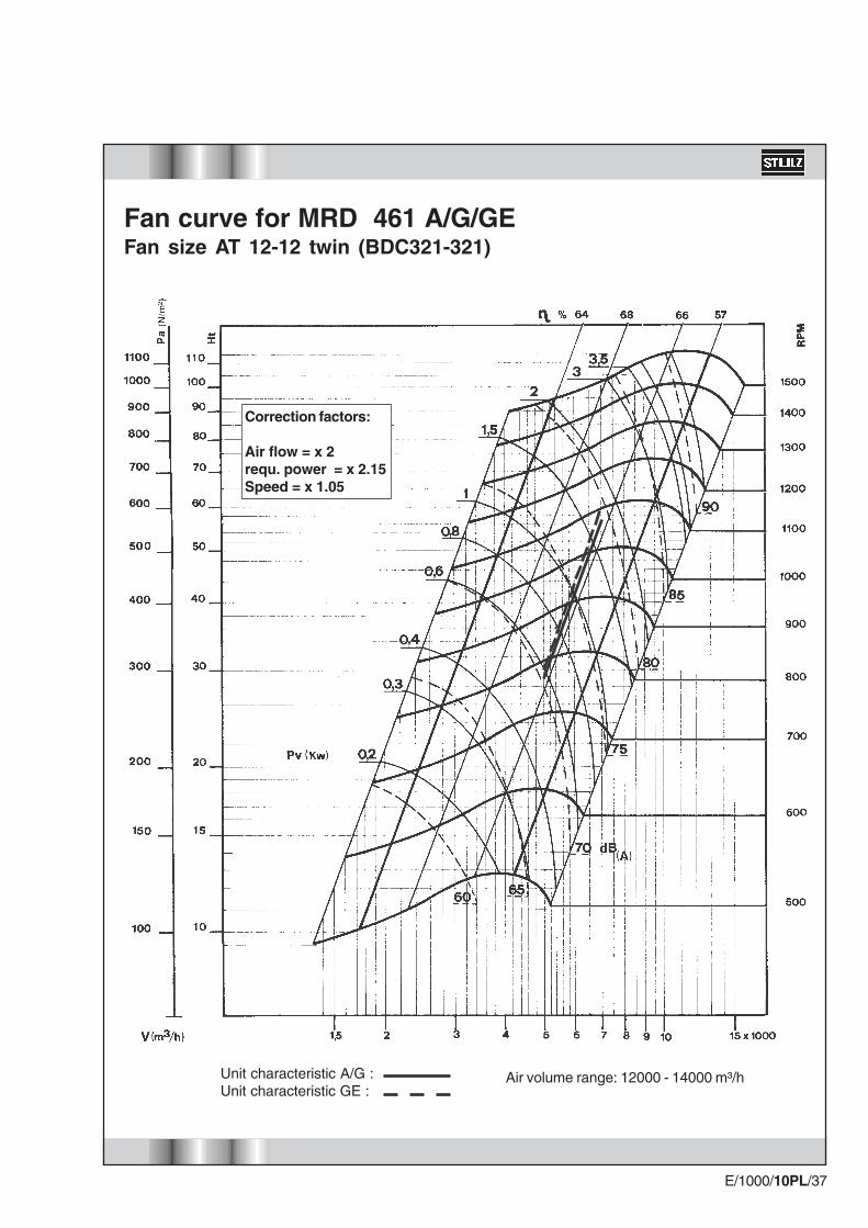
Fan curve for MRD 461 A/G/GEFan size AT 12-12 twin (BDC321-321)
Correction factors:
Air flow = x 2requ. power = x 2.15Speed = x 1.05
Air volume range: 12000 - 14000 m³/hUnit characteristic A/G :Unit characteristic GE :
E/1000/10PL/38
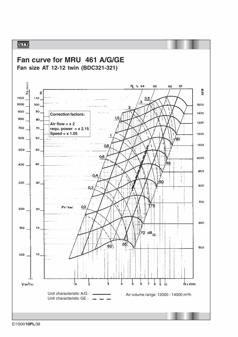
Fan curve for MRU 461 A/G/GEFan size AT 12-12 twin (BDC321-321)
Correction factors:
Air flow = x 2requ. power = x 2.15Speed = x 1.05
Air volume range: 12000 - 14000 m³/hUnit characteristic A/G :Unit characteristic GE :
E/1000/10PL/39
Supply connections
Downflow unitsModule size 181Module size 261Module size 331Module size 381Module size 461
GE units
Upflow unitsModule size 181Module size 261Module size 331Module size 381Module size 461
GE units

E/1000/10PL/40
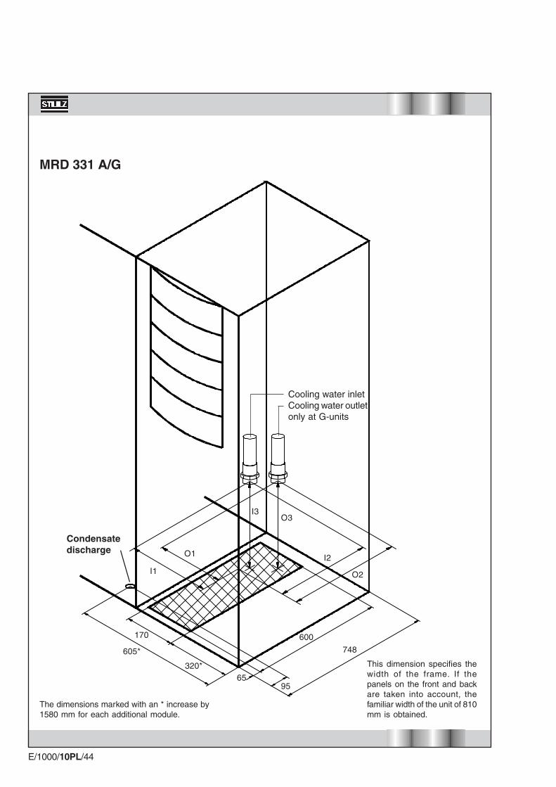
MRD 181 A/G
485*
170
200*
748
600
9565
I1
I2
I3
O1
O2
O3
Cooling water inletCooling water outletonly at G-units
Supply connections of downflow units
This dimension specifies thewidth of the frame. If thepanels on the front and backare taken into account, thefamiliar width of the unit of 810mm is obtained.
The dimensions marked with an * increase by1130 mm for each additional module.
Condensatedischarge
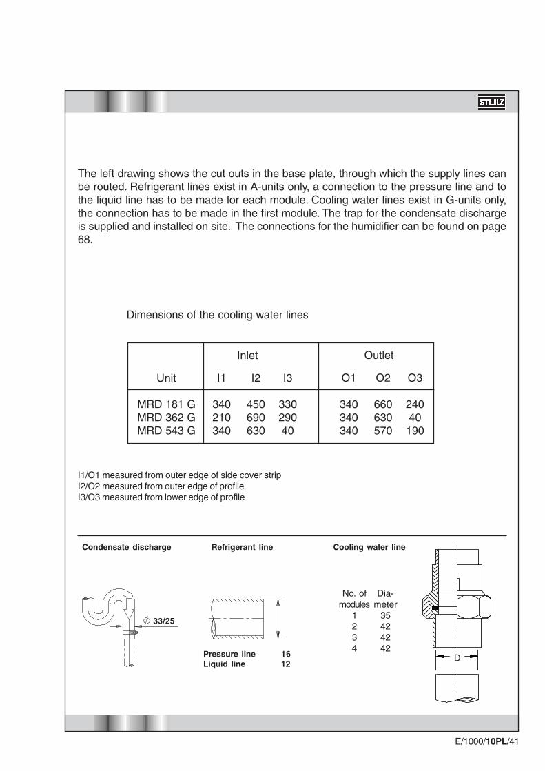
E/1000/10PL/41
I1
340210340
Unit
MRD 181 GMRD 362 GMRD 543 G
I2
450690630
I3
33029040
Inlet
O1
340340340
O2
660630570
O3
24040
190
Outlet
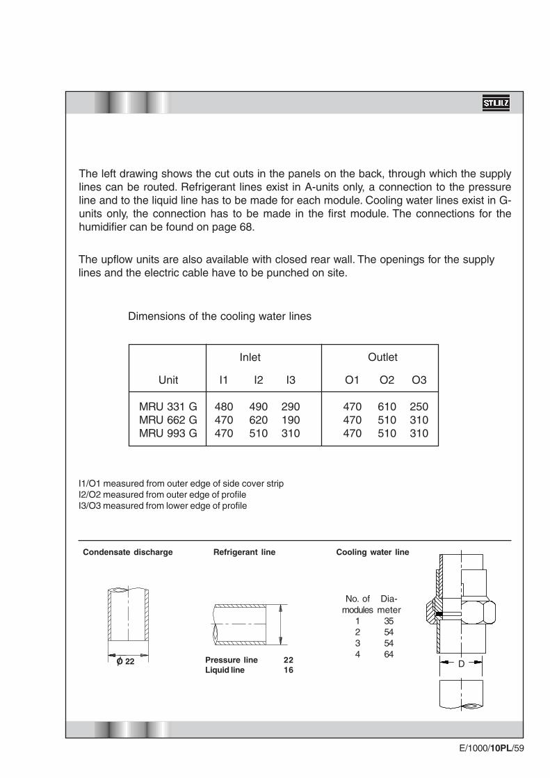
Dimensions of the cooling water lines
The left drawing shows the cut outs in the base plate, through which the supply lines canbe routed. Refrigerant lines exist in A-units only, a connection to the pressure line and tothe liquid line has to be made for each module. Cooling water lines exist in G-units only,the connection has to be made in the first module. The trap for the condensate dischargeis supplied and installed on site. The connections for the humidifier can be found on page68.
33/25
D
I1/O1 measured from outer edge of side cover stripI2/O2 measured from outer edge of profileI3/O3 measured from lower edge of profile
Cooling water line
No. ofmodules
1234
Dia-meter
35424242
Pressure line 16Liquid line 12
Refrigerant lineCondensate discharge

E/1000/10PL/42
535*
170
250*
748
600
9565
I1
I2
I3
O1
O2
O3
MRD 261 A/G
Cooling water inletCooling water outletonly at G-units
This dimension specifies thewidth of the frame. If thepanels on the front and backare taken into account, thefamiliar width of the unit of 810mm is obtained.
The dimensions marked with an * increase by1350 mm for each additional module.
Condensatedischarge

E/1000/10PL/43
I1
380370480
Unit
MRD 261 GMRD 522 GMRD 783 G
I2
65064090
I3
24090290
O1
390370470
O2
440510610
O3
280170250
Inlet Outlet
Dimensions of the cooling water lines
The left drawing shows the cut outs in the base plate, through which the supply lines canbe routed. Refrigerant lines exist in A-units only, a connection to the pressure line and tothe liquid line has to be made for each module. Cooling water lines exist in G-units only,the connection has to be made in the first module. The trap for the condensate dischargeis supplied and installed on site. The connections for the humidifier can be found on page68.
33/25
D
Cooling water line
No. ofmodules
1234
Dia-meter
35425454
Pressure line 16Liquid line 16
Refrigerant lineCondensate discharge
I1/O1 measured from outer edge of side cover stripI2/O2 measured from outer edge of profileI3/O3 measured from lower edge of profile
E/1000/10PL/44
605*
170
320*
748
600
9565
I1
I2
I3
O1
O2
O3
MRD 331 A/G
Cooling water inletCooling water outletonly at G-units
This dimension specifies thewidth of the frame. If thepanels on the front and backare taken into account, thefamiliar width of the unit of 810mm is obtained.
The dimensions marked with an * increase by1580 mm for each additional module.
Condensatedischarge

E/1000/10PL/45
I1
480470470
Unit
MRD 331 GMRD 662 GMRD 993 G
I2
490620510
I3
290190310
O1
470470470
O2
610510510
O3
250310310
Inlet Outlet
Dimensions of the cooling water lines
The left drawing shows the cut outs in the base plate, through which the supply lines canbe routed. Refrigerant lines exist in A-units only, a connection to the pressure line and tothe liquid line has to be made for each module. Cooling water lines exist in G-units only,the connection has to be made in the first module. The trap for the condensate dischargeis supplied and installed on site. The connections for the humidifier can be found on page68.
33/25
D
Cooling water line
No. ofmodules
1234
Dia-meter
35545464
Pressure line 22Liquid line 16
Refrigerant lineCondensate discharge
I1/O1 measured from outer edge of side cover stripI2/O2 measured from outer edge of profileI3/O3 measured from lower edge of profile

E/1000/10PL/46
170
320*
748
600
9565
I1
I2
I3
O1
O2
O3
MRD 381 A/G
605*
Cooling water inletCooling water outletonly at G-units
This dimension specifies thewidth of the frame. If thepanels on the front and backare taken into account, thefamiliar width of the unit of 810mm is obtained.
The dimensions marked with an * increase by1800 mm for each additional module.
Condensatedischarge

E/1000/10PL/47
I1
480470470
Unit
MRD 381 GMRD 762 G
MRD 1143 G
I2
490610620
I3
290190190
O1
470470470
O2
610510510
O3
250310310
Inlet Outlet
Dimensions of the cooling water lines
The left drawing shows the cut outs in the base plate, through which the supply lines canbe routed. Refrigerant lines exist in A-units only, a connection to the pressure line and tothe liquid line has to be made for each module. Cooling water lines exist in G-units only,the connection has to be made in the first module. The trap for the condensate dischargeis supplied and installed on site. The connections for the humidifier can be found on page68.
33/25
D
Cooling water line
No. ofmodules
1234
Dia-meter
35545470
Pressure line 22Liquid line 16
Refrigerant lineCondensate discharge
I1/O1 measured from outer edge of side cover stripI2/O2 measured from outer edge of profileI3/O3 measured from lower edge of profile

E/1000/10PL/48
170
320*
748
600
9565
I1
I2
I3
O1
O2
O3
MRD 461 A/G
605*
Cooling water inletCooling water outletonly at G-units
This dimension specifies thewidth of the frame. If thepanels on the front and backare taken into account, thefamiliar width of the unit of 810mm is obtained.
The dimensions marked with an * increase by2250 mm for each additional module.
Condensatedischarge
E/1000/10PL/49
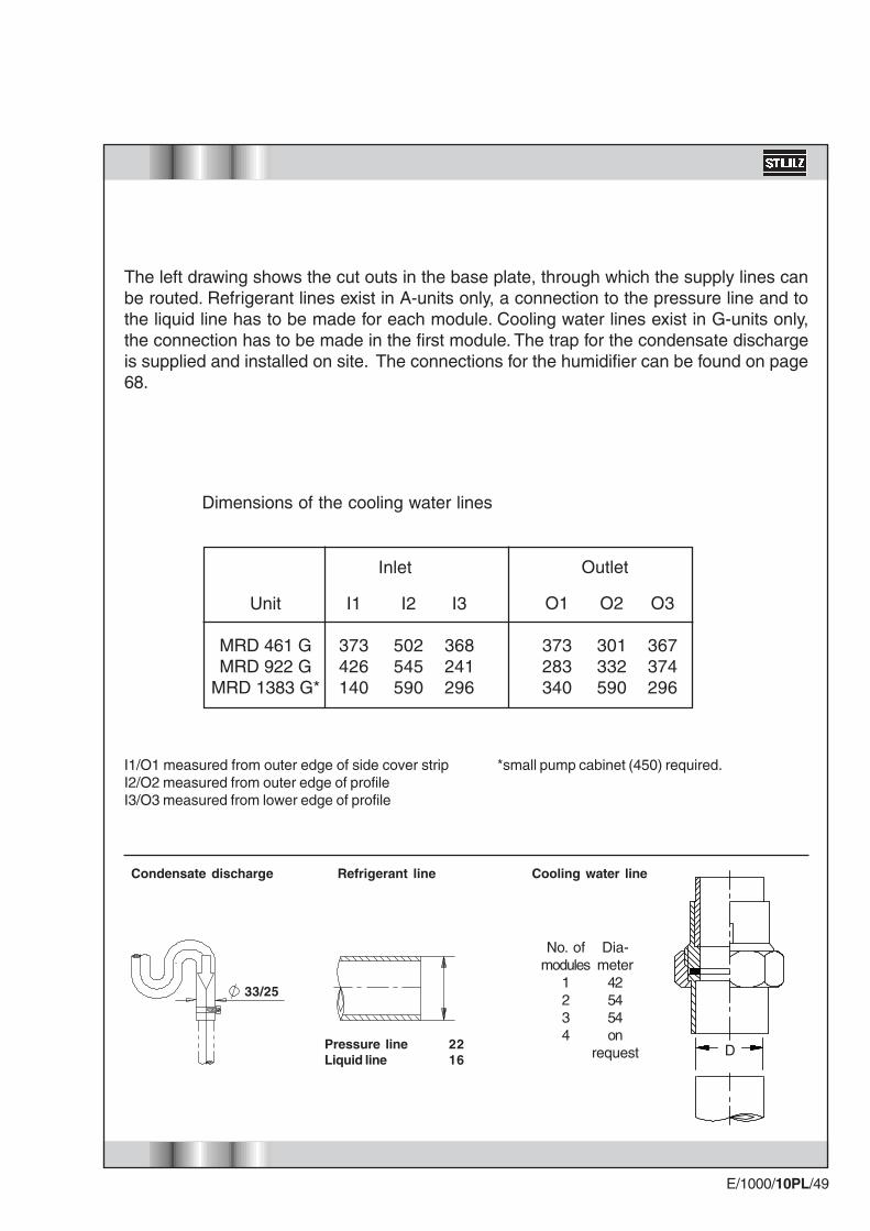
I1
373426140
Unit
MRD 461 GMRD 922 G
MRD 1383 G*
I2
502545590
I3
368241296
O1
373283340
O2
301332590
O3
367374296
Inlet Outlet
Dimensions of the cooling water lines
The left drawing shows the cut outs in the base plate, through which the supply lines canbe routed. Refrigerant lines exist in A-units only, a connection to the pressure line and tothe liquid line has to be made for each module. Cooling water lines exist in G-units only,the connection has to be made in the first module. The trap for the condensate dischargeis supplied and installed on site. The connections for the humidifier can be found on page68.
33/25
D
Cooling water line
No. ofmodules
1234
Dia-meter
425454on
requestPressure line 22Liquid line 16
Refrigerant lineCondensate discharge
I1/O1 measured from outer edge of side cover strip *small pump cabinet (450) required.I2/O2 measured from outer edge of profileI3/O3 measured from lower edge of profile

E/1000/10PL/50
748
I3O3
I2O2
O1
I1
55
145450
145
260
80
70
80
120
GE units with small pump cabinet (version without pump, version with 1 pump)
The cut outs for theelectrical connectionand the humidifier connection havethe same dimensions as the A/Gunits
Condensatedischarge
Electriccables
Cooling water inletCooling water outlet
I1/O1 measured from outer edge of side cover stripI2/O2 measured from outer edge of profileI3/O3 measured from lower edge of profile

E/1000/10PL/51
33/25
Ver
sio
n w
ith
1 p
um
pV
ersi
on
wit
ho
ut
pu
mp
Condensate discharge Piping diameter
I1
140140140
140120100
140120120
120120120
128127358
140140120
140120120
140120120
120120120
128128240
Unit
MRD 181 GEMRD 362 GEMRD 543 GE
MRD 261 GEMRD 522 GEMRD 783 GE
MRD 331 GEMRD 662 GEMRD 993 GE
MRD 381 GEMRD 762 GE
MRD 1143 GE
MRD 461 GEMRD 922 GE
MRD 1383 GE
MRD 181 GEMRD 362 GEMRD 543 GE
MRD 261 GEMRD 522 GEMRD 783 GE
MRD 331 GEMRD 662 GEMRD 993 GE
MRD 381 GEMRD 762 GE
MRD 1143 GE
MRD 461 GEMRD 922 GE
MRD 1383 GE*
!2
160160160
160140120
160100100
140100100
180205119
160160140
160140120
160120120
140120120
205205179
!3
880880880
880880860
880850850
880890850
967933890
800800800
800800830
800830830
800830830
917917650
O1
140140140
14090
120
140120120
120120120
128128284
140140120
140120120
140120120
120120120
128128286
O2
280280280
280300210
280210210
280210210
419419179
280280280
280280210
280210210
280210210
419419279
O3
650650650
650670610
650610610
650610610
693693650
640640640
640640610
640610610
640610610
693693527
Inlet Outlet
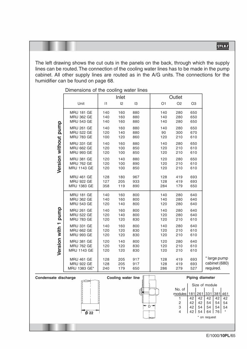
The left drawing shows the cut outs in the base plate, through which the supply lines canbe routed. The connection of the cooling water lines has to be made in the pump cabinet.The trap for the condensate discharge is supplied and installed on site. The connectionsfor the humidifier can be found on page 68.
Dimensions of the cooling water lines
D
* on request
38142545476
33142545464
26142425454
18142424242
No. ofmodules
1234
461425454*
Size of module
Cooling water line
* large pumpcabinet (680)required.

E/1000/10PL/52
748
I2O2
145
260
80
70
145
275680
120
300
O1
I1
I3
O3
GE units with large pump cabinet (version with 2 pumps)
The cut outs for theelectrical connectionand the humidifier connection havethe same dimensions as the A/Gunits
Condensatedischarge
Electriccables
Cooling water inletCooling water outlet
E/1000/10PL/53
33/25
Ver
sio
n w
ith
2 p
um
ps
Condensate discharge
The left drawing shows the cut outs in the base plate, through which the supply lines canbe routed. The connection of the cooling water lines has to be made in the pump cabinet.The trap for the condensate discharge is supplied and installed on site. The connectionsfor the humidifier can be found on page 68.
Dimensions of the cooling water lines
Inlet OutletI1
370370350
370350350
370350350
350350350
358358408
Unit
MRD 181 GEMRD 362 GEMRD 543 GE
MRD 261 GEMRD 522 GEMRD 783 GE
MRD 331 GEMRD 662 GEMRD 993 GE
MRD 381 GEMRD 762 GEMRD 1143 GE
MRD 461 GEMRD 922 GE
MRD 1383 GE*
I2
160160140
160140120
160120120
140120120
205205179
I3
800800800
800800830
800830830
800830850
917917650
O1
370370350
370350350
370350350
350350350
358358454
O2
280280280
280280210
280210210
280210210
419419279
O3
640640640
640640610
640610610
640610610
693693527
Piping diameter
D
* on request
38142545476
33142545464
26142425454
18142424242
No. ofmodules
1234
461425454*
Size of module
Cooling water line
I1/O1 measured from outer edge of side cover strip * spec. pump cabinet (900) required.I2/O2 measured from outer edge of profileI3/O3 measured from lower edge of profile

E/1000/10PL/54
MRU 181 A/G
O2I2
O3O1
I1
I3
1130
170
100
120
100
Supply connections of upflow units
The dimensions marked with an * increase by1130 mm for each additional module.
310
250
155*
125
250
Condensatedischarge
Refrigerant line (A)Cooling water line (G)Humidifier inletHumidifier outletElectric cablesand alternativecondensate outlet
E/1000/10PL/55
I1
340210340
Unit
MRU 181 GMRU 362 GMRU 543 G
I2
450690630
I3
33029040
Inlet
O1
340340340
O2
660630570
O3
24040
190
Outlet
Dimensions of the cooling water lines
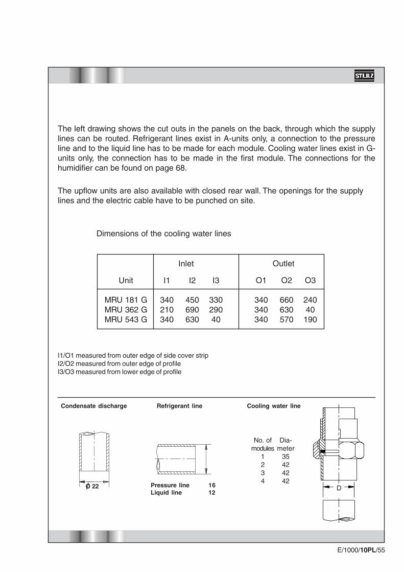
The left drawing shows the cut outs in the panels on the back, through which the supplylines can be routed. Refrigerant lines exist in A-units only, a connection to the pressureline and to the liquid line has to be made for each module. Cooling water lines exist in G-units only, the connection has to be made in the first module. The connections for thehumidifier can be found on page 68.
D
Cooling water line
No. ofmodules
1234
Dia-meter
35424242
Pressure line 16Liquid line 12
Refrigerant lineCondensate discharge
The upflow units are also available with closed rear wall. The openings for the supplylines and the electric cable have to be punched on site.
O 22
I1/O1 measured from outer edge of side cover stripI2/O2 measured from outer edge of profileI3/O3 measured from lower edge of profile

E/1000/10PL/56
MRU 261 A/G
I2
O3O1
I1
I3
O21350
100
170
100
45
120
The dimensions marked with an * increase by1350 mm for each additional module.
310
Condensatedischarge
250
250
335*
Refrigerant line (A)Cooling water line (G)Humidifier inletHumidifier outletElectric cablesand alternativecondensate outlet

E/1000/10PL/57
I1
380370480
Unit
MRU 261 GMRU 522 GMRU 783 G
I2
65064090
I3
24090
290
O1
390370470
O2
440510610
O3
280170250
Inlet Outlet
Dimensions of the cooling water lines
The left drawing shows the cut outs in the panels on the back, through which the supplylines can be routed. Refrigerant lines exist in A-units only, a connection to the pressureline and to the liquid line has to be made for each module. Cooling water lines exist in G-units only, the connection has to be made in the first module. The connections for thehumidifier can be found on page 68.
D
Cooling water line
No. ofmodules
1234
Dia-meter
35425454
Pressure line 16Liquid line 16
Refrigerant lineCondensate discharge
The upflow units are also available with closed rear wall. The openings for the supplylines and the electric cable have to be punched on site.
O 22
I1/O1 measured from outer edge of side cover stripI2/O2 measured from outer edge of profileI3/O3 measured from lower edge of profile

E/1000/10PL/58
MRU 331 A/G
O3 100O2I2
I3O1
I1
170
120
100
1580
The dimensions marked with an * increase by1580 mm for each additional module.
Condensatedischarge
310
250
295*
250125
Refrigerant line (A)Cooling water line (G)Humidifier inletHumidifier outletElectric cablesand alternativecondensate outlet
E/1000/10PL/59
I1
480470470
Unit
MRU 331 GMRU 662 GMRU 993 G
I2
490620510
I3
290190310
O1
470470470
O2
610510510
O3
250310310
Inlet Outlet
Dimensions of the cooling water lines
The left drawing shows the cut outs in the panels on the back, through which the supplylines can be routed. Refrigerant lines exist in A-units only, a connection to the pressureline and to the liquid line has to be made for each module. Cooling water lines exist in G-units only, the connection has to be made in the first module. The connections for thehumidifier can be found on page 68.
D
Cooling water line
No. ofmodules
1234
Dia-meter
35545464
Pressure line 22Liquid line 16
Refrigerant lineCondensate discharge
The upflow units are also available with closed rear wall. The openings for the supplylines and the electric cable have to be punched on site.
O 22
I1/O1 measured from outer edge of side cover stripI2/O2 measured from outer edge of profileI3/O3 measured from lower edge of profile

E/1000/10PL/60
MRU 381 A/G
100
O2I2
O3I3O1
I1
170
10045
120
100
100
The dimensions marked with an * increase by1800 mm for each additional module.
1800
Condensatedischarge
310
250
295*
Refrigerant line (A)Cooling water line (G)Humidifier inletHumidifier outletElectric cablesand alternativecondensate outlet

E/1000/10PL/61
I1
480470470
Unit
MRU 381 GMRU 762 G
MRU 1143 G
I2
490610620
I3
290190190
O1
470470470
O2
610510510
O3
250310310
Inlet Outlet
Dimensions of the cooling water lines
The left drawing shows the cut outs in the panels on the back, through which the supplylines can be routed. Refrigerant lines exist in A-units only, a connection to the pressureline and to the liquid line has to be made for each module. Cooling water lines exist in G-units only, the connection has to be made in the first module. The connections for thehumidifier can be found on page 68.
D
Cooling water line
No. ofmodules
1234
Dia-meter
35545470
Pressure line 22Liquid line 16
Refrigerant lineCondensate discharge
The upflow units are also available with closed rear wall. The openings for the supplylines and the electric cable have to be punched on site.
O 22
I1/O1 measured from outer edge of side cover stripI2/O2 measured from outer edge of profileI3/O3 measured from lower edge of profile

E/1000/10PL/62
MRU 461 A/G
310
100
2250
120
100
250
I2O2
I3
O1I1
O3
230
45250
45*
Condensatedischarge
Refrigerant line (A)Cooling water line(G)Humidifier inletHumidifier outletElectric cablesand alternativecondensate outlet
The dimensions marked with an * increase by2250 mm for each additional module.
E/1000/10PL/63
I1
373426140
Unit
MRU 461 GMRU 922 G
MRU 1383 G
I2
502545590
I3
368241296
O1
373283340
O2
301332590
O3
367374296
Inlet Outlet
Dimensions of the cooling water lines
The left drawing shows the cut outs in the panels on the back, through which the supplylines can be routed. Refrigerant lines exist in A-units only, a connection to the pressureline and to the liquid line has to be made for each module. Cooling water lines exist in G-units only, the connection has to be made in the first module. The connections for thehumidifier can be found on page 68.
D
Cooling water line
No. ofmodules
1234
Dia-meter
425454on
requestPressure line 22Liquid line 16
Refrigerant lineCondensate discharge
The upflow units are also available with closed rear wall. The openings for the supplylines and the electric cable have to be punched on site.
O 22
I1/O1 measured from outer edge of side cover strip *small pump cabinet (450) required.I2/O2 measured from outer edge of profileI3/O3 measured from lower edge of profile

E/1000/10PL/64
100250
55
O1
I1
450
GE units with small pump cabinet (version without pump, version with 1 pump)
310
I2
O2
Cooling water line
I3O3
The upflow units are also available with closedrear wall. The openings for the supply lines andthe electric cable have to be punched on site.
I1/O1 measured from outer edge of side cover stripI2/O2 measured from outer edge of profileI3/O3 measured from lower edge of profile
E/1000/10PL/65
Ver
sio
n w
ith
1 p
um
pV
ersi
on
wit
ho
ut
pu
mp
Condensate discharge Piping diameter
I1
140140140
140120100
140120120
120120120
128127358
140140120
140120120
140120120
120120120
128128240
Unit
MRU 181 GEMRU 362 GEMRU 543 GE
MRU 261 GEMRU 522 GEMRU 783 GE
MRU 331 GEMRU 662 GEMRU 993 GE
MRU 381 GEMRU 762 GE
MRU 1143 GE
MRU 461 GEMRU 922 GE
MRU 1383 GE
MRU 181 GEMRU 362 GEMRU 543 GE
MRU 261 GEMRU 522 GEMRU 783 GE
MRU 331 GEMRU 662 GEMRU 993 GE
MRU 381 GEMRU 762 GE
MRU 1143 GE
MRU 461 GEMRU 922 GE
MRU 1383 GE*
I2
160160160
160140120
160100100
140100100
180205119
160160140
160140120
160120120
140120120
205205179
I3
880880880
880880860
880850850
880890850
967933890
800800800
800800830
800830830
800830830
917917650
O1
140140140
14090
120
140120120
120120120
128128284
140140120
140120120
140120120
120120120
128128286
O2
280280280
280300210
280210210
280210210
419419179
280280280
280280210
280210210
280210210
419419279
O3
650650650
650670610
650610610
650610610
693693650
640640640
640640610
640610610
640610610
693693527
Inlet OutletDimensions of the cooling water lines
D
* on request
38142545476
33142545464
26142425454
18142424242
No. ofmodules
1234
461425454*
Size of module
Cooling water line
The left drawing shows the cut outs in the panels on the back, through which the supplylines can be routed. The connection of the cooling water lines has to be made in the pumpcabinet. All other supply lines are routed as in the A/G units. The connections for thehumidifier can be found on page 68.
O 22
* large pumpcabinet (680)required.

E/1000/10PL/66
100
O3I3
680
I1 O1
GE units with large pump cabinet (version with 2 pumps)
310
Cooling water line
250
315
O2I2

E/1000/10PL/67
The left drawing shows the cut outs in the base plate, through which the supply lines canbe routed. The connection of the cooling water lines has to be made in the pump cabinet.All other supply lines are routed as in the A/G units. The connections for the humidifier canbe found on page 68.
Ver
sio
n w
ith
2 p
um
ps
Condensate discharge
Dimensions of the cooling water lines
Inlet OutletI1
370370350
370350350
370350350
350350350
358358408
Unit
MRU 181 GEMRU 362 GEMRU 543 GE
MRU 261 GEMRU 522 GEMRU 783 GE
MRU 331 GEMRU 662 GEMRU 993 GE
MRU 381 GEMRU 762 GEMRU 1143 GE
MRU 461 GEMRU 922 GE
MRU 1383 GE*
I2
160160140
160140120
160120120
140120120
205205179
I3
800800800
800800830
800830830
800830850
917917650
O1
370370350
370350350
370350350
350350350
358358454
O2
280280280
280280210
280210210
280210210
419419279
O3
640640640
640640610
640610610
640610610
693693527
Piping diameter
D
* on request
38142545476
33142545464
26142425454
18142424242
No. ofmodules
1234
461425454*
Size of module
Cooling water line
O 22
The upflow units are also available with closed rear wall. The openings for the supplylines and the electric cable have to be punched on site.
I1/O1 measured from outer edge of side cover strip * spec. pump cabinet (900) required.I2/O2 measured from outer edge of profileI3/O3 measured from lower edge of profile

E/1000/10PL/68
Supply connections of humidifiers
Ultrasonic humidifierSteam humidifier
Steam humidifierInlet
Steam humidifierOutlet
Ultrasonic humidifierInlet
3/4"
Plastic hose
U U
D D

E/1000/10PL/69
Duct connections on unit frame, on the top of the unit
Fixing for side panel M6
Air section Pump section
d1
688.5858.51018.51238.51688.5
L
10671287151717372187
L
15171737196721872637
d2
10921315154517652215
L
17471967219724172867
Basic units withone pumps
Basic units withtwo pumpsBasic units
The drawing above shows the dimensions of the aluminiumsections to which the air duct is attached using St.4.9. sheetmetal screws.The aluminium section is shown in the cross section in the dia-gram opposite.
Here, a canvas connecting piece or a duct can be secured withM8 bolts. The thread must be cut by hand.
Lowtemperature
section
MRD/U 181MRD/U 261MRD/U 331MRD/U 381MRD/U 461
E/1000/10PL/70
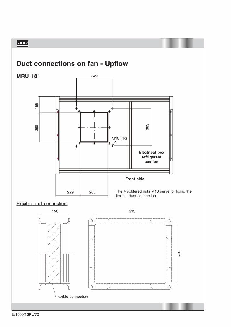
Duct connections on fan - Upflow
289
156
229 265
349
369
150 315
flexible connection
335
Flexible duct connection:
MRU 181
The 4 soldered nuts M10 serve for fixing theflexible duct connection.
M10 (4x)
Electrical boxrefrigerant
section
Front side
E/1000/10PL/71
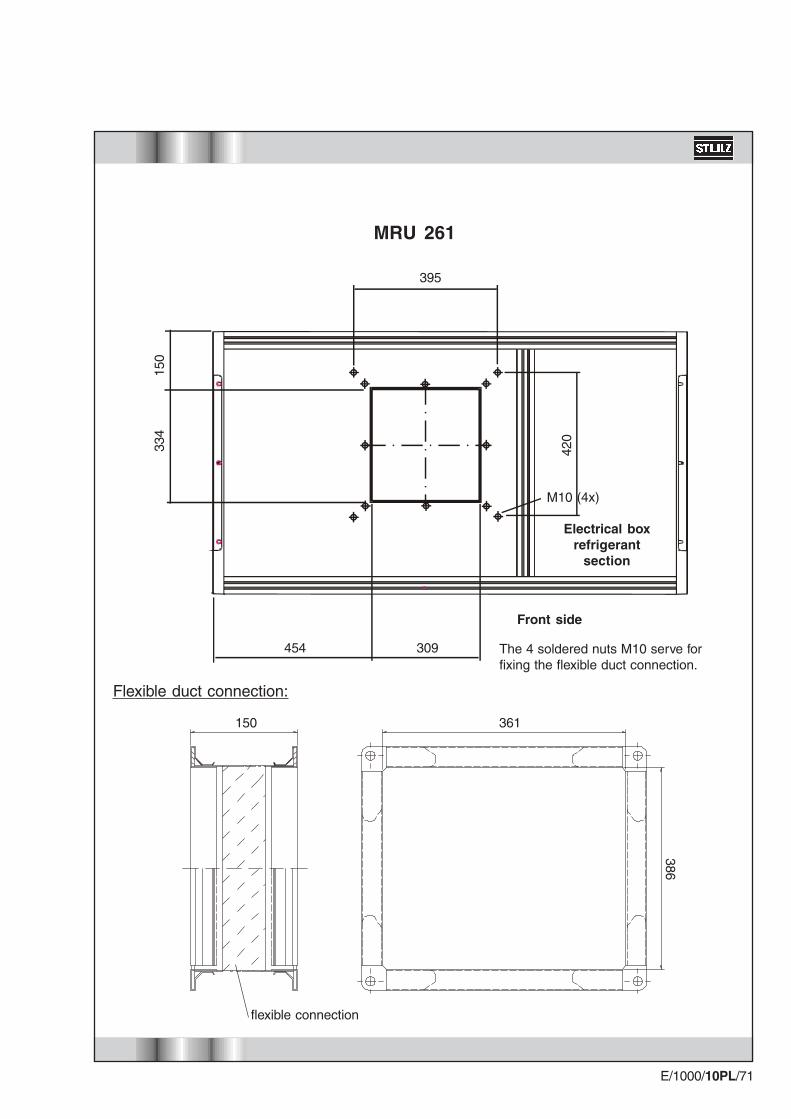
334
150
MRU 261
150 361
flexible connection
386
Flexible duct connection:
The 4 soldered nuts M10 serve forfixing the flexible duct connection.
M10 (4x)
420
395
454 309
Electrical boxrefrigerant
section
Front side

E/1000/10PL/72
397
118
150 520
448
Flexible duct connection:
554
M10 (4x)
482
422 471
The 4 soldered nuts M10 serve forfixing the flexible duct connection.
MRU 331
flexible connection
Electrical boxrefrigerant
section
Front side

E/1000/10PL/73
397
118
150 520
448
Flexible duct connection:
M10 (4x)
554
580 471
482
MRU 381
flexible connection
Electrical boxrefrigerant
section
Front side
The 4 soldered nuts M10 serve forfixing the flexible duct connection.

E/1000/10PL/74
MRU 461
150 447
386
420
M10 (8x)
334
150
481 481
432 395 347 395
Electrical boxrefrigerant
section
Front side
The 4 soldered nuts M10 serve forfixing the flexible duct connection.
Flexible duct connection: 2x
flexible connection
E/1000/10PL/75
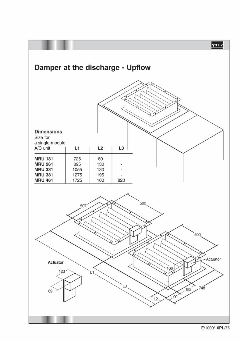
Damper at the discharge - Upflow
Actuator
123
69
Actuator
500
500507
748192
90L2
L1
L3
106
DimensionsSize fora single-moduleA/C unit L1 L2 L3
MRU 181 725 80MRU 261 895 130 -MRU 331 1055 130 -MRU 381 1275 195 -MRU 461 1725 100 820

E/1000/10PL/76
Damper with flexible duct connection at the discharge -Upflow
150 510
flexible connection
500
Flexible duct connection:
The dimensions of the dampercorrespond to the dimensionson the preceding page.
E/1000/10PL/77
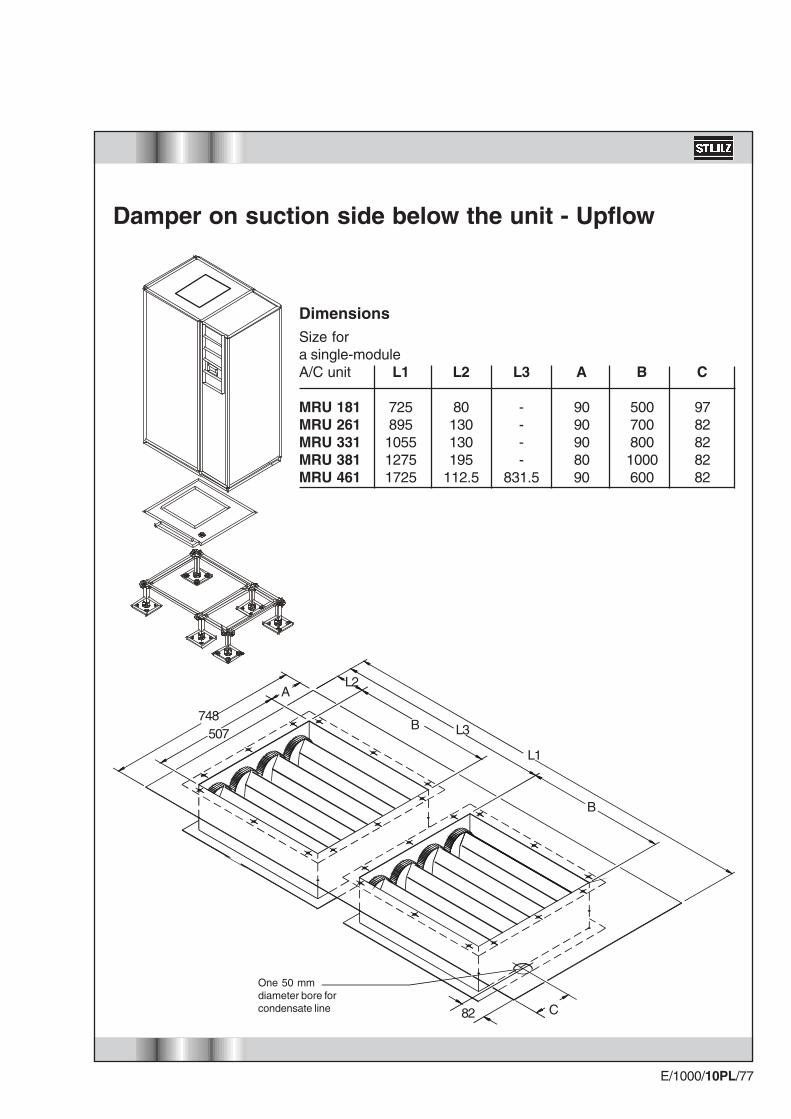
Damper on suction side below the unit - Upflow
82 C
B
B
L1
L2
L3748
507
A
One 50 mmdiameter bore forcondensate line
Size fora single-moduleA/C unit L1 L2 L3 A B C
MRU 181 725 80 - 90 500 97MRU 261 895 130 - 90 700 82MRU 331 1055 130 - 90 800 82MRU 381 1275 195 - 80 1000 82MRU 461 1725 112.5 831.5 90 600 82
Dimensions
E/1000/10PL/78
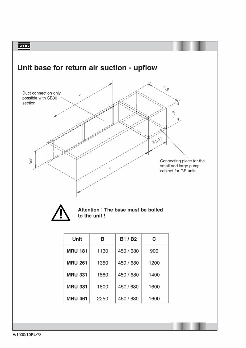
Unit base for return air suction - upflow
Duct connection onlypossible with SB30section
Connecting piece for thesmall and large pumpcabinet for GE units
Attention ! The base must be boltedto the unit !
C
900
1200
1400
1600
1600
B1 / B2
450 / 680
450 / 680
450 / 680
450 / 680
450 / 680
B
1130
1350
1580
1800
2250
Unit
MRU 181
MRU 261
MRU 331
MRU 381
MRU 461

E/1000/10PL/79
Flexible duct connection at the unit base - Upflow
150 B
flexible connection
360
Flexible duct connection:
B
9001200140016001600
Unit
MRU 181MRU 261MRU 331MRU 381MRU 461
E/1000/10PL/80
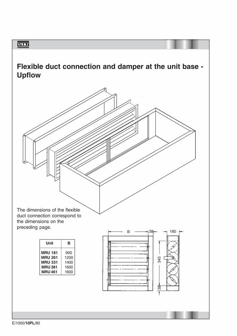
Flexible duct connection and damper at the unit base -Upflow
B 18038
3834
5
The dimensions of the flexibleduct connection correspond tothe dimensions on thepreceding page.
B
9001200140016001600
Unit
MRU 181MRU 261MRU 331MRU 381MRU 461
E/1000/10PL/81
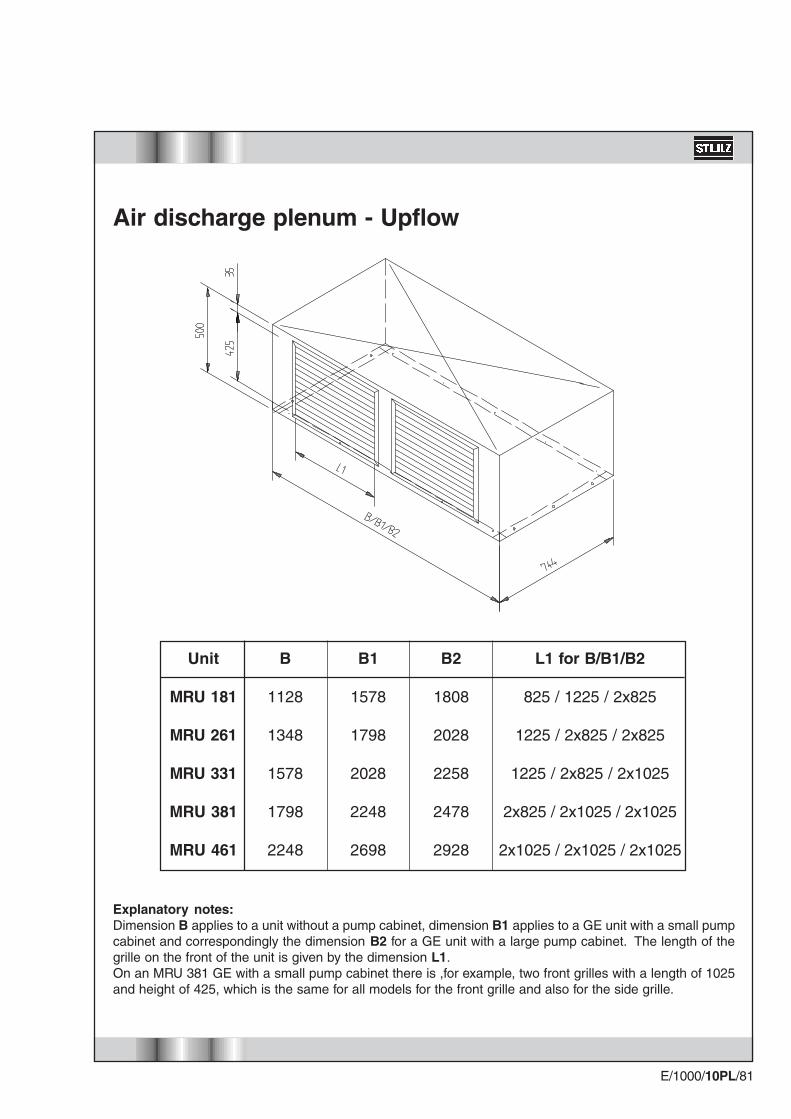
Air discharge plenum - Upflow
Explanatory notes:Dimension B applies to a unit without a pump cabinet, dimension B1 applies to a GE unit with a small pumpcabinet and correspondingly the dimension B2 for a GE unit with a large pump cabinet. The length of thegrille on the front of the unit is given by the dimension L1.On an MRU 381 GE with a small pump cabinet there is ,for example, two front grilles with a length of 1025and height of 425, which is the same for all models for the front grille and also for the side grille.
B2
1808
2028
2258
2478
2928
L1 for B/B1/B2
825 / 1225 / 2x825
1225 / 2x825 / 2x825
1225 / 2x825 / 2x1025
2x825 / 2x1025 / 2x1025
2x1025 / 2x1025 / 2x1025
B1
1578
1798
2028
2248
2698
B
1128
1348
1578
1798
2248
Unit
MRU 181
MRU 261
MRU 331
MRU 381
MRU 461
E/1000/10PL/82
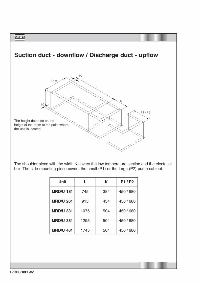
Suction duct - downflow / Discharge duct - upflow
The height depends on theheight of the room at the point wherethe unit is located.
The shoulder piece with the width K covers the low temperature section and the electricalbox. The side-mounting piece covers the small (P1) or the large (P2) pump cabinet.
L
745
915
1075
1295
1745
Unit
MRD/U 181
MRD/U 261
MRD/U 331
MRD/U 381
MRD/U 461
K
384
434
504
504
504
P1 / P2
450 / 680
450 / 680
450 / 680
450 / 680
450 / 680

E/1000/10PL/83
Damper on suction side on the air section - Downflow
500
500507
748
AL2
L1
L3
DimensionsSize fora single-moduleA/C unit L1 L2 L3 A B
MRD 181 725 80 - 90 500 MRD 261 895 130 - 90 700 MRD 331 1055 130 - 90 800 MRD 381 1275 195 - 80 1000 MRD 461 1725 112.5 831.5 90 600
E/1000/10PL/84
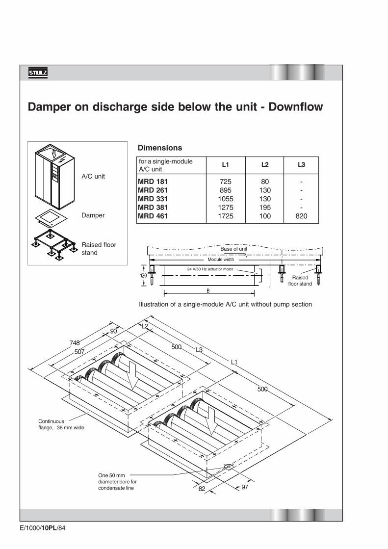
L1 L2 L3
MRD 181 725 80 -MRD 261 895 130 -MRD 331 1055 130 -MRD 381 1275 195 -MRD 461 1725 100 820
Damper on discharge side below the unit - Downflow
Base of unit
Module width
24 V/50 Hz actuator motor
Raisedfloor stand
Illustration of a single-module A/C unit without pump section
Raised floorstand
Damper
A/C unit
Dimensions
for a single-moduleA/C unit
82 97
L1
L2
L3748
507
90
500
500
Continuousflange, 38 mm wide
One 50 mmdiameter bore forcondensate line
E/1000/10PL/85
Unit
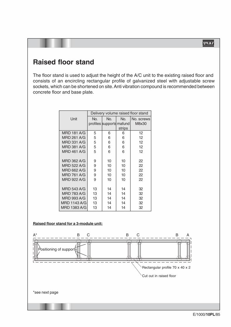
MRD 181 A/GMRD 261 A/GMRD 331 A/GMRD 381 A/GMRD 461 A/G
MRD 362 A/GMRD 522 A/GMRD 662 A/GMRD 761 A/GMRD 922 A/G
MRD 543 A/GMRD 783 A/GMRD 993 A/GMRD 1143 A/GMRD 1383 A/G
*see next page
Positioning of supports
A* B C B C B A
Raised floor stand for a 3-module unit:
Raised floor stand
The floor stand is used to adjust the height of the A/C unit to the existing raised floor andconsists of an encircling rectangular profile of galvanized steel with adjustable screwsockets, which can be shortened on site. Anti vibration compound is recommended betweenconcrete floor and base plate.
Rectangular profile 70 x 40 x 2
Cut out in raised floor
No.profiles
55555
99999
1313131313
No.supports
66666
1010101010
1414141414
No.mafundstrips
66666
1010101010
1414141414
No. screwsM8x30
1212121212
2222222222
3232323232
Delivery volume raised floor stand

E/1000/10PL/86
Angle Connection Butt Joint Cross Connection
Connecting the bars(View from below)
X/Y = Opening in raised floor Z = Limit of distance
- the raised floor cutting (notch) should at least be 15°and must not have any contact to the raised floorstand, which could result in bone-conduction.
- the dimensions of the openings in the raised floor (Xand Y) are 10 mm longer than the raised floor stand.The joint must be closed by customers with acontinuous seal.
- a concrete foundation is recommended in the areaof the raised floor supports.
- the raised floor supports have to be installed onvibration dampening material (do not screw downthe supports!).
- prior to installation of the A/C unit, the raised floormust be installed 7 mm higher than the raised floorplates, as the mafund plates are compressed by theweight of the A/C unit.
Minimum distances and mounting instructions
Raised floor stand
X Z
Z (min. 30)
Y
Z (min. 800)Z(min. 30)
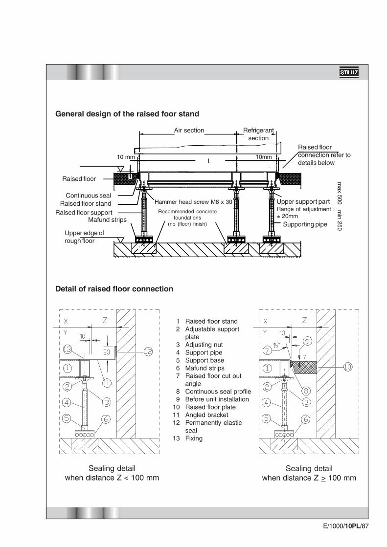
E/1000/10PL/87
Raised floor standAdjustable supportplateAdjusting nutSupport pipeSupport baseMafund stripsRaised floor cut outangleContinuous seal profileBefore unit installationRaised floor plateAngled bracketPermanently elasticsealFixing
12
34567
89
101112
13
Sealing detailwhen distance Z < 100 mm
Sealing detailwhen distance Z > 100 mm
Detail of raised floor connection
Recommended concretefoundations
(no (floor) finish)Mafund strips
Upper edge ofrough floor
Raised floor supportRaised floor stand
Continuous seal
Raised floor
Raised floorconnection refer todetails below
○
○
○
○
○
○
○
○
○
○
10 mm 10mm
max 500 m
in 250
Upper support partRange of adjustment :± 20mm
Supporting pipe
Hammer head screw M8 x 30
General design of the raised foor stand
Air section Refrigerantsection
L
E/1000/10PL/88
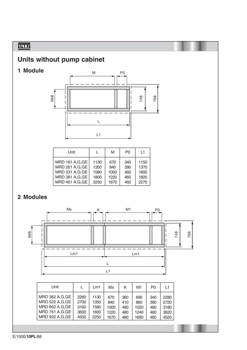
Units without pump cabinet
1 Module
2 Modules
M
66
8
Unit
MRD 181 A,G,GEMRD 261 A,G,GEMRD 331 A,G,GEMRD 381 A,G,GEMRD 461 A,G,GE
L
11301350158018002250
M
670840100012201670
P0
340390460460460
L1
11501370160018202270
76
8
74
8
P0
L1
L
76
8
74
8
M1 P0KMx
66
8
L1
Lm1 Lm1
L
Unit
MRD 362 A,G,GEMRD 522 A,G,GEMRD 662 A,G,GEMRD 761 A,G,GEMRD 922 A,G,GE
Lm1
11301350158018002250
L
22602700316036004500
L1
22802720318036204520
P0
340390460460460
Mx
670840100012201670
K
360410480480480
M1
690860102012401690

E/1000/10PL/89
3 Modules
76
8
74
8
66
8
KMx M1 K M1 P0
Lm1Lm1Lm1
L1
L
Unit
MRD 543 A,G,GEMRD 783 A,G,GEMRD 993 A,G,GEMRD 1143 A,G,GEMRD 1383 A,G,GE
Lm1
11301350158018002250
L
33904050474054006750
L1
34104070476054206770
P0
340390460460460
K
360410480480480
M1
690860102012401690
Mx
670840100012201670
E/1000/10PL/90
76
8
74
8
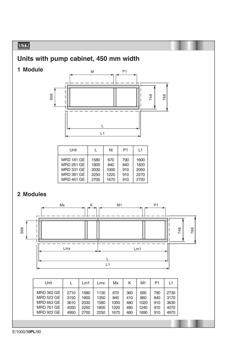
Units with pump cabinet, 450 mm width
1 Module
66
8
L1
L
Lm1Lmx
P1M1Mx K
2 Modules
Unit
MRD 362 GEMRD 522 GEMRD 662 GEMRD 761 GEMRD 922 GE
L1
27303170363040704970
P1
790840910910910
Lm1
15801800203022502700
Mx
670840100012201670
L
27103150361040504950
Lmx
11301350158018002250
K
360410480480480
M1
690860102012401690
P1M
66
8
L
L1
76
8
74
8
Unit
MRD 181 GEMRD 261 GEMRD 331 GEMRD 381 GEMRD 461 GE
L
15801800203022502700
M
670840100012201670
P1
790840910910910
L1
16001820205022702720
E/1000/10PL/91
Unit
MRD 543 GEMRD 783 GEMRD 993 GEMRD 1143 GEMRD 1383 GE
L1
38604520521058707220
P1
790840910910910
Lm1
15801800203022502700
Mx
670840100012201670
L
38404500519058507200
Lmx
11301350158018002250
K
360410480480480
M1
690860102012401690
3 Modules
P1M1Mx K M1 K
66
8
Lm1LmxLmx
L
76
8
74
8
L1

E/1000/10PL/92
Unit
MRD 181 GEMRD 261 GEMRD 331 GEMRD 381 GEMRD 461 GE
L
18102030226024802930
M
670840100012201670
P2
10201070114011401140
L1
18302050228025002950
76
8
74
8
L1
L
P2M
66
8
Units with pump cabinet, 680 mm width
1 Module
76
8
74
8
66
8
L1
L
Lm1Lmx
P2M1Mx K
2 Modules
Unit
MRD 362 GEMRD 522 GEMRD 662 GEMRD 761 GEMRD 922 GE
L1
29603400386043005200
P2
10201070114011401140
Lm1
18102030226024802930
Mx
670840100012201670
L
29403380384042805180
Lmx
11301350158018002250
K
360410480480480
M1
690860102012401690
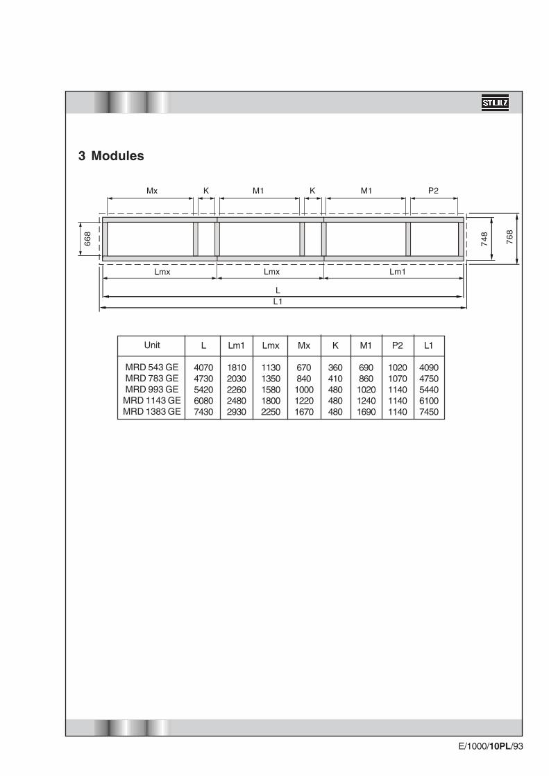
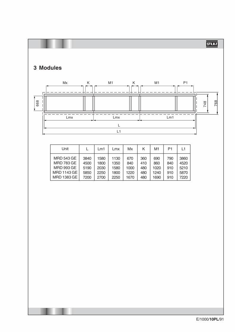
E/1000/10PL/93
Unit
MRD 543 GEMRD 783 GEMRD 993 GEMRD 1143 GEMRD 1383 GE
L1
40904750544061007450
P2
10201070114011401140
Lm1
18102030226024802930
Mx
670840100012201670
L
40704730542060807430
Lmx
11301350158018002250
K
360410480480480
M1
690860102012401690
3 Modules
P2M1Mx K M1 K
76
8
74
8
66
8
Lm1LmxLmx
L1L

E/1000/10PL/94
Hot gas lines depending onthe overall pipe lengths andrefrigeration outputs.
Liquid lines depending onthe overall pipe lengths andrefrigeration outputs.
Pipe dimensions
Diagram No. 1: Diagrams for designing the refrigerant lines for R407c/R22
Ove
rall
pip
e le
ng
th i
n m
Refrigeration output in kW
Refrigeration output in kW
Ove
rall
pip
e le
ng
th i
n m
Outside dia. in m
m
Outside dia. in m
m
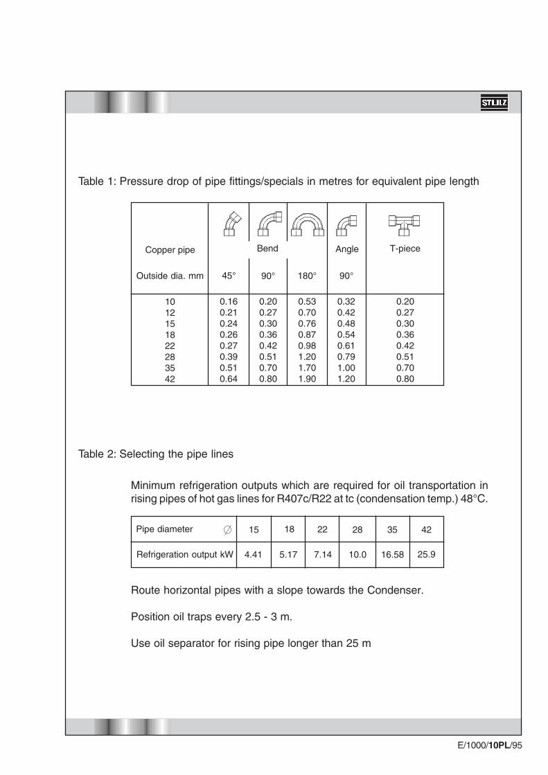
E/1000/10PL/95
Minimum refrigeration outputs which are required for oil transportation inrising pipes of hot gas lines for R407c/R22 at tc (condensation temp.) 48°C.
Route horizontal pipes with a slope towards the Condenser.
Position oil traps every 2.5 - 3 m.
Use oil separator for rising pipe longer than 25 m
Pipe diameter
Refrigeration output kW
15 18 22 28 35 42
7.145.174.41 10.0 16.58 25.9
1012151822283542
0.160.210.240.260.270.390.510.64
0.200.270.300.360.420.510.700.80
0.530.700.760.870.981.201.701.90
0.320.420.480.540.610.791.001.20
0.200.270.300.360.420.510.700.80
Outside dia. mm 90°45° 180° 90°
Copper pipe T-pieceAngle
Table 1: Pressure drop of pipe fittings/specials in metres for equivalent pipe length
Table 2: Selecting the pipe lines
Bend

E/1000/10PL/96
X
Alternative ways of combining the options
Suc
tion
thro
ttle
2-po
int
stea
m h
umid
ifier
Con
stan
t st
eam
hum
idifi
er
2-po
int
ultr
ason
ic E
NS
Con
stan
t ul
tras
onic
EN
S
Pha
se c
ontr
ol
Ele
ctric
al h
eatin
g st
age
2
Ref
riger
ant
heat
ing
Lphw
* he
atin
g pr
opor
t. (e
xter
nal)
Rem
ote
on/o
ff
Act
uatio
n of
GE
pum
p
Act
uatio
n of
dry
cool
er
Seq
uenc
ing
Combining the options is not possible
This option always requires an extension-I/O Board
X X X X
Suction throttle
2-point steam humidifier
Constant steam humidifier
2-point ultrasonic ENS
Constant ultrasonic ENS
Phase control
Electrical heating stage 2
Refrigerant heating
Lphw* heating proport. (external)
Remote on/off
Actuation of GE pump
Actuation of drycooler
Sequencing
Extension I/O Board
X*Lphw heating = Low pressure hot water heating
E/1000/10PL/97
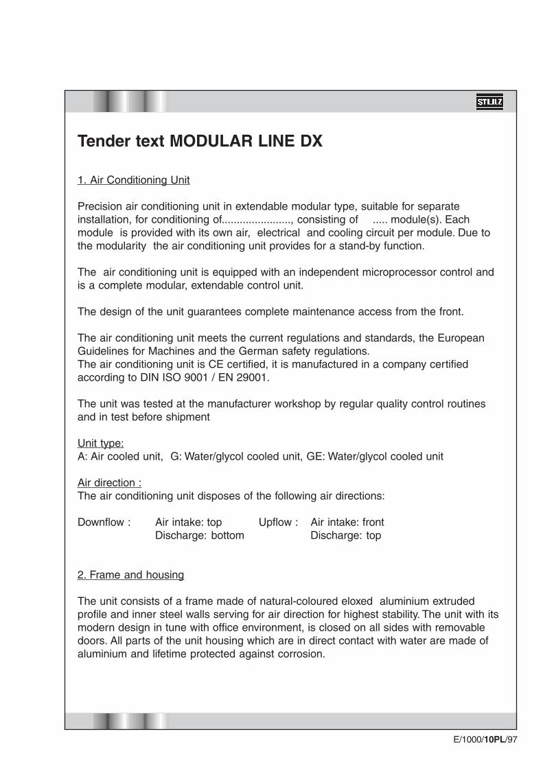
Tender text MODULAR LINE DX
1. Air Conditioning Unit
Precision air conditioning unit in extendable modular type, suitable for separateinstallation, for conditioning of......................., consisting of ..... module(s). Eachmodule is provided with its own air, electrical and cooling circuit per module. Due tothe modularity the air conditioning unit provides for a stand-by function.
The air conditioning unit is equipped with an independent microprocessor control andis a complete modular, extendable control unit.
The design of the unit guarantees complete maintenance access from the front.
The air conditioning unit meets the current regulations and standards, the EuropeanGuidelines for Machines and the German safety regulations.The air conditioning unit is CE certified, it is manufactured in a company certifiedaccording to DIN ISO 9001 / EN 29001.
The unit was tested at the manufacturer workshop by regular quality control routinesand in test before shipment
Unit type:A: Air cooled unit, G: Water/glycol cooled unit, GE: Water/glycol cooled unit
Air direction :The air conditioning unit disposes of the following air directions:
Downflow : Air intake: top Upflow : Air intake: frontDischarge: bottom Discharge: top
2. Frame and housing
The unit consists of a frame made of natural-coloured eloxed aluminium extrudedprofile and inner steel walls serving for air direction for highest stability. The unit with itsmodern design in tune with office environment, is closed on all sides with removabledoors. All parts of the unit housing which are in direct contact with water are made ofaluminium and lifetime protected against corrosion.

E/1000/10PL/98
3. Exterior Panelwork for MRD/U-Units
Panelwork on the front and the rear of the unit is made by hinged doors.
The complete panelwork is assembled to the unit frame with special security fastenerswhich prevent from unauthorized access to the units.
All panels and doors are isolated from low frequency noise transmissions by specialrubber seals.
The panelwork is lined out with a noise absorbing polyester fibre insulation, which isthermally treated. The thickness of the insulation is 35 mm. The insulation is accordingto DIN 4102 hardly inflammable, the classification is B 1, self distinguishing.Panels are designed to stand a total air pressure difference of 1000 Pascals.Panels are sealed against each other with special joggling teeth.The colour of the panelwork and all the sheet metal work is STULZ-pure-white.
4. Filter
4.1 EU4 Filter
MRD :In the housing located on the suction side of the coil, with large zig-zag filter surface, ina cardboard frame completely combustible, filter quality EU4.Changing the filter is possible from the front only.Differential pressure switch for indication of clogged filter.
MRU :Filter placed in the housing on the suction side with regenerateable filter mat in metalfilter cassette, quality EU4.Changing the filter is possible from the front only.Differential pressure switch for indication of clogged filter.
4.2 EU5 Filter (Option)
MRD :In the housing located on the suction side of the coil, with large zig-zag filter surface, ina cardboard frame completely combustible, filter quality EU5.Changing the filter is possible from the front only.Differential pressure switch for indication of clogged filter.

E/1000/10PL/99
MRU :Filter placed in the housing on the suction side of the coil, with zig-zag filter surfaceand metal filter frame, quality EU5.Changing the filter is possible from the front only.Differential pressure switch for indication of clogged filter.
5. refrigerant evaporator
A high capacity direct expanison coil per module made of copper tubes with pressed-on, corrugated aluminium fins. Inclined position of the evaporator, aluminiumcondensate pan and aluminium joint plates guarantee the drain of condensate indehumidification mode.The coils are designed in a way that in normal operation no dehumidification takesplace, and only sensible cooling capacity is provided.The direct evaporator is located on suction side of the fan for reducing the air pressuredrops by creating a very even, low air velocity and so providing a high efficiency of theheat transferring surface of the coil.
5.1 dehumidification circuit (Option)
dehumidification is achieved by an additional split of the Dx-coil including a secondrefrigerant injection and a solenoid valve.
In case of dehumidification the solenoid valve is activated by the microprocessor andcuts off approximately one third of the evaporator surface. The remaining two thirds ofthe evaporator surface are now causing a lower surface temperature due to the reducedcoil surface. This effect causes a drop of the air temperature below the due point andcondensates water from the return air. The airflow is not affected in the dehumidificationmode.
6. fans
6.1. V-belt drive
One high capacity radial fan per module, with forward curved blades, low revolutions,low noise emission, with maintenance-free bearings, lubricated for lifetime, staticallyand dynamically balanced, galvanized housing with additional epoxy powder coating asa high quality corrosion protection.Fan drive by high capacity belts to meet changed customer’s requirements, such as airvolume flow or higher required external pressure. Belt drives by V-belt pulleys, whichare mounted on bushings and therefore quickly interchangeable.
E/1000/10PL/100
Fan motors: Standard motors, three phase motors mounted on adjustable base enableeasy tensioning of the belt drives.Motor and fan are mounted on a common reinforced framework. High capacity V-beltdrive is calculated for low vibration operation and long life cycles. The large calculatedV-belt pulleys reduce the necessary tensioning forces to a minimum.
6.2 Flat-belt drive (Option)
Fan drive by flat-belts made of non abrasion material, for adjusting to alternatingcustomer requirements such as air flow or necessary external static pressure beltdrives by pulleys, which are mounted on bushings and therefore quicklyinterchangeable.Fan motors: standard motor, three phase motors mounted on adjustable base enablestensioning of the belt drives.Motor and fan are mounted on a common reinforced framework made of stainless steel.High capacity flat belt drive is calculated for low vibration operation and long life cycles.The large calculated flat belt pulleys reduce the needed tensioning forces to aminimum.
7. Scroll compressor
1 hermetic scroll compressor per module with increased EER (energy efficiency ratio),locking device, non return valves in discharge line and crank-case heater are notreqiured, elasticly mounted with anti-vibration dampers on the extruded aluminiumprofile of the unit housing.
Accessories: compressor and other heat-emitting components located separately fromthe airstream, filter-dryer, liquid receiver with rotalock valve, sight-glass with humidityindicator, thermostatic expansion-valve, rotalock valves on the compressor dischargeline, low pressure switch, high pressure switch TÜV approved with manual reset, checkvalves in liquid line, 4 schrader-valves per circuit for pressure gauge connection.- solenoid valve in the liquid line and pressure relief valve (only for unit type A).
E/1000/10PL/101
8. Technical data of the unit
Unit:Unittype:Air direction:Power supply: V / Ph / HzAirflow: m³/hReturn air temperature: °CRel. return air humidity: %Condensation temperature: °CHeight: mmDepth: mmWidth: mmWeight: kgManufacturer: STULZModel: MR... ....... ....
Fan:Fantype:Nominal power of motor: kWPower consumption motor: kWBelt type:P external: PaP total: PaNumber of revolutions: U/min
Evaporator:Air discharge temperature: °CRel. humidity air discharge: %Total refrigerant capacity: kWSensible refrigerant capacity: kW
Compressor:Nominal power: kWCurrent consumption: AMax. operating current: A
Cooler: (only GE)Air discharge temperature: °CRel. humidity air discharge: %Total cooling capacity: kWSensible cooling capacity: kW
Pressure losses:Pressure loss condenser: kPaPressure loss 3-way head pressurecontrol valve: kPaPressure loss cooler: kPaPressure loss 3-way control valve: kPaTotal pressure loss: kPaNominal size 3-way head pressurecontrol valve: inchNominal size 3-way control valve: inch
Medium data:Medium inlet temperature: °CMedium outlet temperature: °CPercentage of glycol %
E/1000/10PL/102
9. condensers
9.1 high-effiency condenser(s), air cooled (only for unit type A)
1 condenser per module, made of corrosion-resistant aluminium casing, suitable forhorizontal or vertical installation.
Coil made of copper tubes and pressed-on aluminium fins.
Standardized axial fan(s) with mounting support(s) including protection againstaccidental contact, on/off control by pressure switch(es), already completely wired.Terminal box for power input, water protected IP 54.
1 Schrader valve for connecting pressure gauge during adjustment of condenser switchwhen unit is set-up.
Technical data :
Condenser model : KS.....................Power supply : 230V / 1Ph / N / 50Hz / PEAir entering temperature : ° CCondensing temperature : ° CAltitude above sea level : mCondenser capacity : kWSound pressure level in5 m distance ( free field ) : dB(A)Number of fan(s) : piece(s)Current consumption per fan : AWeight : kg
9.1.1 fan speed controller (only for unit type A) (Option)
Proportional fan speed controller in accordance with condensing temperature andoutdoor temperature.
9.2 water/glycol cooled condenser per module (Option) (only for unit type G and GE)
Stainless steel plate fin condenser, compact design, material according to DIN 17440material no. 1.4571 V4A for excellent heat transfering coefficient, therefore small
E/1000/10PL/103
temperature difference between water inlet temp. and condensing temp., maximumworking pressure 30 bars, completely insulated with armaflex, 14 mm thickness, toprevent condensate on the cold surface of the heat-exchnager.
9.2.1 3 - way head pressure control valve (only for unit type GE) (Option for unit type G)
Cooling water quantity control by one 3 - way head pressure control valve per module,controlled by the refrigerant pressure for adaption of the cooling water quantity to theactual requirement and for constant condensation temperature.
9.2.2 2 - way head pressure control valve (Option) (only for unit type G)
Cooling water quantity control by one 2 - way head pressure control valve per module,controlled by the refrigerant pressure for adaption of the cooling water quantity to theactual requirement and for constant condensation temperature.
9.2.3 water temperature sensor (Option) (only for unit type G and GE)
Water temperature sensor to supervise the cooling water, for optical alarm in case ofhigh water temperature and for control of dry cooler fan motor(s).
10. cooling coil for "free cooling" to economise energy (only for unit type GE)
The energy costs for the heat removal are reduced to 50% by the additional heatexchanger.At outside temperatures below 7 - 9°C (depending on the design) the water coil takesover the cold air production of the unit at 100%. The compressor system is thenswitched off completely.In the interseasons like spring and autumn at outside temperature below 19°C the watercoil has a pre-cooling function, so that the compressor system has only to deliver a partof the cooling capacity. The run time of the compressors are reduced significantly.
The water coil is designed for a water/glycol mixture of 70/30%.
11. 3-way proportional control valve for controlling the cooling capacity of the coil inenergy saving operation (only for unit type GE):
With sinking water temperatures in the dry cooler system, the 3-way control valvecontrols the water flow through the cooling coil dependent of the room/return air
E/1000/10PL/104
temperature. The valve is equipped with a proportional actuator with a power supply of24 VAC and a control voltage of 0-10 VDC.
12. pump cabinet per unit (only for unit type GE)
At the right side of the unit one cabinet is installed for the pumps and the water pipingincluding the 3-way control valve.The pump cabinet housing consists of a frame made of natural-coloured eloxedaluminium extruded profile and inner steel walls.The pump cabinet is conform with the unit design. Doors, panels and frame parts arelifetime protected against corrosion by a coating of synthetic material.The panelwork is lined out at the inside with a noise absorbing insulation, which has athickness of 35 mm. (classification see exterior panelwork)
Equipment variants of pump cabinet : (optional)
12.1 Standard variant with the following equipment
Stulz 3-way valve with a power supply of 24 VAC and a control voltage of 0-10 VDC fortemperature control of the cooling coil for free cooling, 2 thermometers in in- and outlet,2 shut-off valves for the entire unit, 1 filling and drain valve for the water/glycol circuit.
12.2 Variant with one pump and the following equipment
Stulz 3-way valve with a power supply of 24 VAC and a control voltage of 0-10 VDC fortemperature control of the cooling coil for free cooling, 2 thermometers in in- and outlet,2 shut-off valves for the entire unit, 2 pressure gauges with glycerine filling up- anddownstream of the pump, 1 safety valve with pressure gauge, 1 expansion tank with 18 lvolume, 1 high pressure centrifugal pump multi-stage with runner and housing ofstainless steel, 1 non-return valve.The control of the pump is realized by the electric cabinet of the unit, the electrical partslike contactors and MCBs of the pump are housed in the electric cabinet of the unit.
12.3 Variant with two pumps and the following equipment
Stulz 3-way valve with a power supply of 24 VAC and a control voltage of 0-10 VDC fortemperature control of the cooling coil for free cooling, 2 thermometers in in- and outlet,2 shut-off valves for the entire unit, 2 pressure gauges with glycerine filling up- anddownstream of the pump, 1 safety valve with pressure gauge, 1 expansion tank with 18 lvolume, 2 high pressure centrifugal pumps multi-stage with runners and housing ofstainless steel, 2 non-return valves downstream of the pumps to prevent inverse flow incase of stand-by operation of one pump.

E/1000/10PL/105
The control of the pump is realized by the electric cabinet of the unit, the electrical partslike contactors and MCBs of the pump are housed in the electric cabinet of the unit.
13. heaters
13.1 electrical reheat (Option)
installed per module, in stages of 6 or 12 KW, made of chrome-nickel-steel finned rods,fins made of chrome-nickel-steel to reduce surface temperature and frame made ofgalvanized-steel. Each stage is protected by an overheat-thermostat and an additionalcircuit breaker in every electrical box in the modules.
reheat capacity: KW/stagenos. of stages:
(max. 2 stages per module)
13.2 hotgas reheat (Option)
For reheating the airflow without additional energy input in dehumidification mode incase of low heat load of the room, made of copper tubes with pressed-on aluminiumfins. Hot gas is discharged via a 3-way-valve to the hotgas reheat coil and afterwards tothe condenser.
Reheat capacity, approx.: .. 80% of nominal cooling capacityof the moduleReheat medium: hotgas refrigerant
14. humidifier
14.1 steam humidifier, installed per module (Option)
for full automatic production and discharge of odourless and demineralized steam.Suitable for direct connection to tap water. Nominal pressure 1-6 bars. Steam capacityin the range of 25-100% of the nominal capacity adjustable on the unit.Completely assembled as a kit including a strainer, an inlet and outlet solenoid valve, asteam cylinder with the boiling electrodes, separate control devices, contactors andautonomous control microprocessor for all modes of operation.
Humidifier is separated from the airflow and can be serviced without interrupting theoperation of the unit or disturbing the air flow.
E/1000/10PL/106
Long service cycle due to large volume steam cylinder, replaceable within minutes.
Maximized life cycle due to automatic drainage procedure by an electronic watercontrol, independent from various water qualities, minimized water consumption. Start-up by switching on the humidifier without previous water analysis and additional checkafterwards.
Steam capacity: ... kg/hPower input: ... KWHumidifier model: OEM ...
14.1.1 Proportional control for steam humidifier by a special E-Prom (Option)
14.2 Ultrasonic humidifier installed per module (Option)
for production and discharge of odourless and demineralized mist by ultrasonic waves.Lowest power and water consumption. Germproof humidification, the bacteriologicalcontamination is prevented by ultrasonic waves.
The Ultrasonic humidifier consists of:
Plastic housing
and a modular extension of mist producing transducers, an electronic control part anda module with water inlet solenoid valve, dry-operation protection and a water levelcontrol.
Installation kitmade of stainless steel and stainless screws, washers and nuts.
Water drip trayfor additional water leakage protection.
Transformer sec. 48 V, for control cabinet installation
The Ultrasonic humidifier can only be used in accordance with a conductimeter anddemineralized water.

E/1000/10PL/107
Technical data:
Humidifier capacity: kg/hNos. of transducers: nos.Nominal capacity: WattPower connection: 48 V / 1 Ph / 50 HzPhysical dimensions:Width/height/depth: mmWeight: kgManufacturer: STULZHumidifier model: ENS
14.2.1 conductimeter incl. sensor (Option)
for water quality control
1. alarm indication (with 5 µS/cm):pre-alarm, replacement of D/I - bottle, check reverse osmosis
2. alarm indication (with 20 µS/cm):failure humidifier, switch off humidifier
An indication of the actual status of the water quality can be connected to the electroniccontrol device.Measurements are taken in Volts (1 Volt = 50 µS/cm)
14.2.2 regenerateable deionized water bottle (D/I- bottle) (Option)
installed per module, consisting of a pressure tested stainless steel bottle for producingmineral-free water.The bottle is filled with negatively and positively charged material and ready for use.
Technical data:Capacity at 20 degrees totalmineral contents of tap water: 2000 lmax. water temperature: 30°Cmax. water working pressure: 6 barmanufacturer: STULZmodel: S 26

E/1000/10PL/108
15. control cabinets
1 electrical cabinet per module for installation of all high voltage components permodule.The cabinet guarantees a full maintenance access from the front. A separatepower supply of each module enables a connection to different power supplies or UPS.Due to this concept a complete redundancy of all high voltage components isguaranteed.
The high-voltage components per module are:- circuit breakers- contactors- isolators
mounted on rails in the cabinet.
The components are completely wired with a cable harness and protected by ducts.Terminals, cables and components are identified. I/O-modules of the microprocessorare additionally installed in the control box of the module.
16. microprocessor C5000
For controlling of an air conditioning unit and supervising of room temperature andhumidity limits. Equipped with an user-friendly, illuminated, large surface LCD - display.The software is structured in three different levels: Information, Operation and Servicewhich can be operated by a user friendly windows-technique via the display and thekeys.Each module is controlled separatly with different control circuits for temperature andhumidify. The controller is suitable for return air, room or supply air control. The controllogic is a P-logic.The control system consists of a processor including a display and input keys as wellas decentralized I/O-boards located in every module and connected via a bus-wire.The data bus is quick, reliable, standardized CAN-data-bus which is used in theautomotive industry.
16.1 modular system control
In case of a stand-by module configuration the stand-by function is sequenced over allpresent modules.
In case of failure on one of the modules in operation, the automatic switch overactivates the stand-by module.
In case of power interruption the unit can be automatically or manually restarted. Thetime delay of the restart, as well as the time delay for restarting the single components,
E/1000/10PL/109
is adjustable.
Running hour meter for the unit, running hours of the separate modules and the singlecomponents are indicated in the display.
Records of the previous 80 alarms with date and time, alarm delays adjustable,priorities of the alarms adjustable text for auxillary alarms can be selected individually.
Cyclic self-test of controller, input and parameters are checked on plausibility, sensorfailure is checked by the microprocessor.
Record of the previous 80 events like,- failure of power supply- start / stop status- stand-by start- alarm reset- all alarms
Calibration of temperature and humidity sensorsSensors of C 5000 can be calibrated by adjusting indicated values to actual valueswhich are shown by different devices also used in the room.
Maintenance requestThe request for service and maintenance work can be indicatedby the controller, ifpreviously maintenance intervals are defined and adjusted.
High room load operationIn case of temporary high room heat loads the controller can activate stand-by modulefor a short period of time to increase the cooling capacity. The stand-by module isswitched off automatically when the unregular heat load is removed.
Water temperature control (only for unit type GE)- only in combination with the water temperature sensor and the outside
temperature sensor -Every 4 hours the dry cooler is switched on for 10 minutes. If the water temperature inthis time reaches a temperature of 2 Kelvin below the setpoint for the return airtemperature, a changeover is made to winter operation. This happens in the same way,if an outside air temperature is measured (by an additionally installed outside airsensor), which is 8 Kelvin below the setpoint for the return air temperature.

E/1000/10PL/110
16.2 LCD - graphic display
LCD graphic display for indication of :-real time-actual values of temperature and humidity-symbols for operation modes cooling, reheat, dehumidification and humidificationsimple, user-friendly operation of the controller by modern window techniquegraphic diagrams of temperature and humidity for the last 24 hours
-Room-, supply-, fresh-air- and water-temperature (G and GE only), room- andsupply-humidity including indication of set valves and limits
-alarm indications- temperature high and low- humidity high and low- air flow- clogged filter- high / low pressure refrigerant circuit- humidifier failure- 8 different, further alarms on customers request ( depend on equipment of unit ) :
i. e. - failure reheat stage 2i. e. - failure condenser fan
-status indications- activated stand-by operation- maintenance request- activated UPS operation (without humidification and reheat)
-detailed operation status- i. e. day / night cycling- unit / module and component running times
The graphic display can be switched to various languages and different character sets.
16.3 STULZ-microprocessor-interfaces
For data transmission and communication the following interfaces areprovided:
-serial printer interface for failure protocols and intervals of temperature andhumiditiy values (RS232)
-serial PC-interface (RS232) für diagnosis and configuration.
Optional as piggy back:
-BMS-interface (2x RS485, 1x RS232) for systems as-L&G

E/1000/10PL/111
-Honeywell-Trend-STULZ-Telemonitoring-Staefa
-8 adjustable analog inputs (0 - 20 mA / 0 - 10 V)
17. raised floor stands (Option)
consisting of an extruded rectangular profile, 72,5 x 40 x 2 mm, made of galvanizedsteel, with adjustable thread poles. Height, max./min. (500/250 mm):pole diameter: 26 mm
Base plate for ground installation on an anti - vibration dampening rubber gasket.Connection plate to rectangular profile by hammer head screws. Physical dimensions inaccordance with unit dimensions.
18. louvers (Option)
for installation on the discharge side of the unit or in raised floor to avoid short cycle ofsupply air when modules are operated separately or in case of service or maintenancework.
Frames and fins made of galvanized steel, drives made of aluminium, bearing-hubsmade of cadmium - plated steel, bearing-hubs made of special plastics.
Physical dimensions in accordance with unit dimensions per separate module.
18.1 actuators (Option)
Actuator for adjusting of louvers.The output signal is provided as on/off signal, which can be converted. The controldevices are installed in the control box.

E/1000/10PL/112
AppendixThe following manuals are available for the product ranges:
Product range Index Type of manual
MODULAR LINE DX 10 Operating instructionsMODULAR LINE DX 10PL Planning manualMODULAR LINE CW 11 Operating instructionsMODULAR LINE CW 11PL Planning manualMODULAR LINE CHILLER 40 Operating instructionsMODULAR LINE CHILLER 40PL Planning manual
MINI-SPACE 20 Operating instructions with planning partDAU 40 CW 21 Operating instructionsCompact CW 22 Operating instructionsConsole STD/U 23 Operating instructionsCOM-AIR 24 Operating instructionsWALL-AIR 25 Operating instructions
SAF 101 A (400V) 30 Operating instructionsSAF 101 A (208/220V) 31 Operating instructionsSAD 111 A 32 Operating instructions
C 1002 50 Operating instructionsC 5000 52 Operating instructionsC 5000 - Chiller 53 Operating instructionsC 6000 54 Operating instructionsInCompTrol 60 Operating instructionsSequencing-Box 61 Operating instructionsTeleCompTrol 62 Operating instructionsNI Stulz 63 Operating instructionsSDC - C4000 64 Operating instructionsGateway Stulz/Honeywell 65 Operating instructionsSDC - C5000 66 Operating instructionsLandis & Gyr Interface 67 Operating instructionsModbus 68 Operating instructionsSatchwell 69 Operating instructions
Condensers 80 Technical DataInternal condensers 81 Operating instructions
Option manual 91 Function description
For further information please contact our marketing department.
STULZ GmbH - Holsteiner Chaussee 283 - D22457 HamburgTel.: 040/5585-239 Fax: 040/5585-308