Doug’s Guide to the XTS 3000 Radio - akardam.net · how many times I’ve seen radios in the used...
69
Batdude’s Guide for the XTS 3000 - XTS 5000 and Astro Digital Saber 3 September 2006 Revised 3 November 2006
Transcript of Doug’s Guide to the XTS 3000 Radio - akardam.net · how many times I’ve seen radios in the used...

Batdude’s Guide for the
XTS 3000 - XTS 5000and Astro Digital Saber
3 September 2006Revised 3 November 2006

As I sat down today to install a NTN8255 DES-OFB module into an XTS 3000 portable radio, I thought some of you would appreciate an informal walkthrough of the tips to disassemble the radio and get it back together again without any damage. I can’t count how many times I’ve seen radios in the used market that have case damage due to improper disassembly. The key to the entire process is this:

Without this tool, I can guarantee that you will either split the end of the case plastic, as shown in the below picture, or gouge/destroy the protective o-ring.
This is an actual radio that I purchased at dayton….

Of course, I’ll show you this, just because Ithink it’s indicative of how about 80% of thepeople out there open up their radios:

Okay, you have finally ordered your handy-dandy white opener tool, Motorola part number 6685833D01 (cost is about $4.00) and you’re ready to crack the case. I can give you the rhetoric about ESD safety now – obviously what you are seeing
here is on the border of ESD-unsafe. However, I’m not sitting here rubbing my cat while my feet are on the carpet either. This procedure should (of course) be
conducted at an ESD approved workbench while wearing a wrist strap. Note how the hinge of the tool “captures” the frame.
MAKE SURE THE ANTENNA HAS BEEN REMOVED BEFORE DOING THIS!
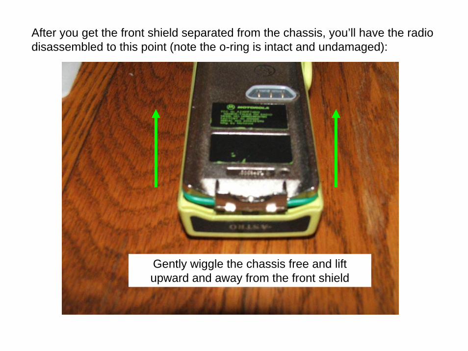
After you get the front shield separated from the chassis, you’ll have the radio disassembled to this point (note the o-ring is intact and undamaged):
Gently wiggle the chassis free and lift upward and away from the front shield

Separating the front shield flex from the chassis can be tricky, but you’ll get the hang of it – you can use your thumb to pop the flex connector off:
The white part here is the connector, the black is the plastic flex support – very gently pry downward on the black support and the connector will unmate with little or no effort.

Two things in this picture – one is the connector type – this is a “B” series connector (notice how wide it is with the male plug in the center). The second item is the green universal connector plug retainer.
Notice the lip at the bottom of this retainer. This is a modification that is required to prevent wear on the flex. See the next slide.
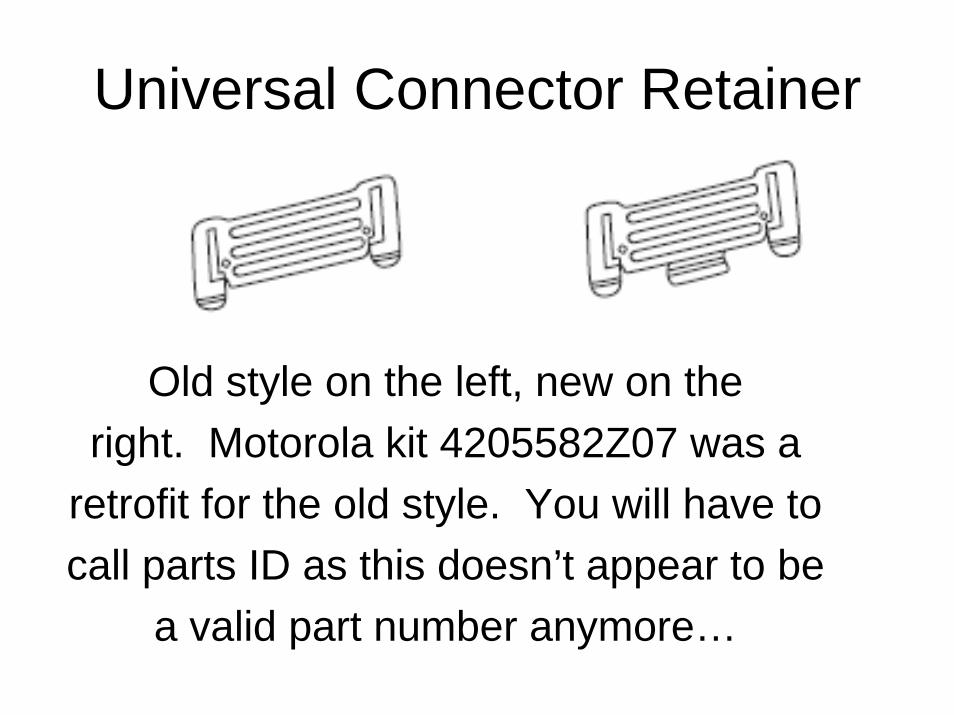
Universal Connector Retainer
Old style on the left, new on theright. Motorola kit 4205582Z07 was a
retrofit for the old style. You will have tocall parts ID as this doesn’t appear to be
a valid part number anymore…

A Series vs. B Series Housings“A” Series radios (I.e. H09RDH9PW7AN) use a different controllerboard (NCN6128) that has a different plug on it for connecting thefront housing. This is CRUCIAL when ordering replacement partsfor your radio! In the below picture, the “B” series is on the LEFT.

Ok, back on track….In the below picture, you see the radio with the front shield completely removed.
LCD Flex retainer bracket – has two snaps that must be pried upward to remove
One of the most common assembly errors is right here. This brown “finger” is part of the flex for the LCD. There is a slot in the retainer to allow this finger to stick out and be compressed against the frame during re-assembly.
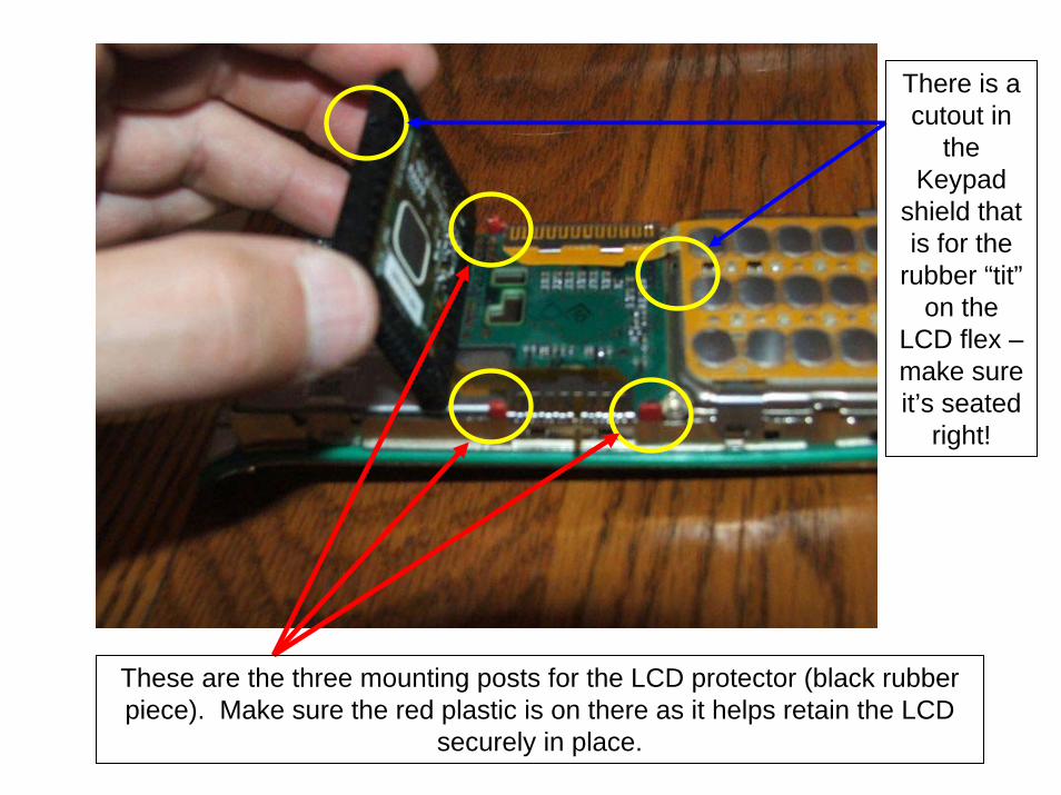
These are the three mounting posts for the LCD protector (black rubber piece). Make sure the red plastic is on there as it helps retain the LCD
securely in place.
There is a cutout in
the Keypad
shield that is for the
rubber “tit”on the
LCD flex –make sure it’s seated
right!

I normally just use the plastic special tool for this, but a small flat
blade screwdriver works just as well. Note the
“finger” of the LCD flex sticking out.
This is the keypad flex retainer, again – a small flat blade works well here too.

There are four small retainers that must be released to remove the keypadFlex assembly. Once removed you can remove the entire keypad flex assembly and set it aside. Note the flex retainer is completely released
from the chassis.

There is a small cutout that forms a notch that holds the NCN6167 controller board in place. If you gently lift the
controller board up from the BOTTOM of the radio, it will slip right out of the radio. Ensure the top of the controller board
engages this retainer notch during reassembly!

Nice view of the NCN6167
controller board and LCD assembly
after partial removal…..oh by
the way… that controller board is about $400… and the LCD is about
$80… so BE CAREFUL!
(FYI, this board stores your HOST
firmware).
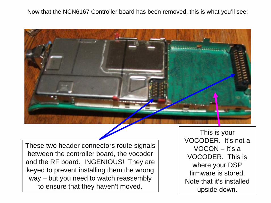
This is your VOCODER. It’s not a
VOCON – It’s a VOCODER. This is
where your DSP firmware is stored.
Note that it’s installed upside down.
These two header connectors route signals between the controller board, the vocoder
and the RF board. INGENIOUS! They are keyed to prevent installing them the wrong way – but you need to watch reassembly
to ensure that they haven’t moved.
Now that the NCN6167 Controller board has been removed, this is what you’ll see:

The NTN8250 VOCODER
Be careful – don’t fry it or drop it – current
replacement cost is around $400.00
Note the keying lugs on these connectors – they’re supposed to
be “sailor proof” – be sure you put them in right!

Removing the RF Shield… not required for my project… but shown to you!
There is one retainer clip on the left side that must be removed….this is the same style clip as the keypad….
And two detents need to be “popped” on the right hand side to remove the RF shield…..
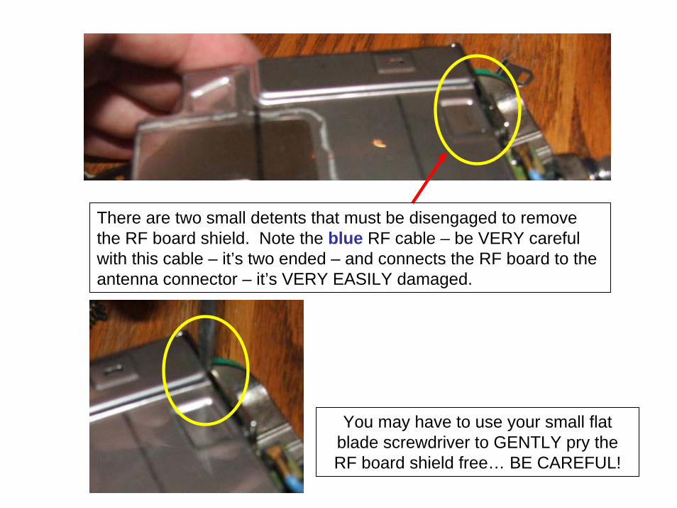
There are two small detents that must be disengaged to remove the RF board shield. Note the blue RF cable – be VERY careful with this cable – it’s two ended – and connects the RF board to the antenna connector – it’s VERY EASILY damaged.
You may have to use your small flat blade screwdriver to GENTLY pry the RF board shield free… BE CAREFUL!

RF Shield removed…..
The RF board is removed by lifting it from the LEFT side (long silver can) and tilting it upward to free the two retainers from their detents in the chassis (yellow circles)… if you are removing the RF board completely, use a small pair of hemostats or fine needlenose pliers to remove the RF cable from it’s socket on the RF board…..

Ok.. What I was really here for…
This is a side view of the secure module and it’s mounting tray. Note the gap between the secure module and the retainer – THIS IS NOT INSTALLED CORRECTLY and must be fixed before installation….

Lay the secure module in the retainer tray as shown. There are notches in this tray that will retain the board. Lay it flat as shown and then slide it to the left –and it will be under the notches. DO NOT FORCE IT –and DO NOT bend the metal retainer!

Notice how the secure board lays flat in the mounting tray – and note the bend in the tray (the “V” shape) – this is the correct layout!

There are two detents on the LEFT HAND SIDE that must be engaged FIRST. Once they have snapped into place, use your screwdriver to GENTLY press down on the right side of the RETAINER (NOT THE
BOARD!) and it will snap into place. Once this is done, check your 2
interconnect header connectors to make sure they are still oriented
correctly…..
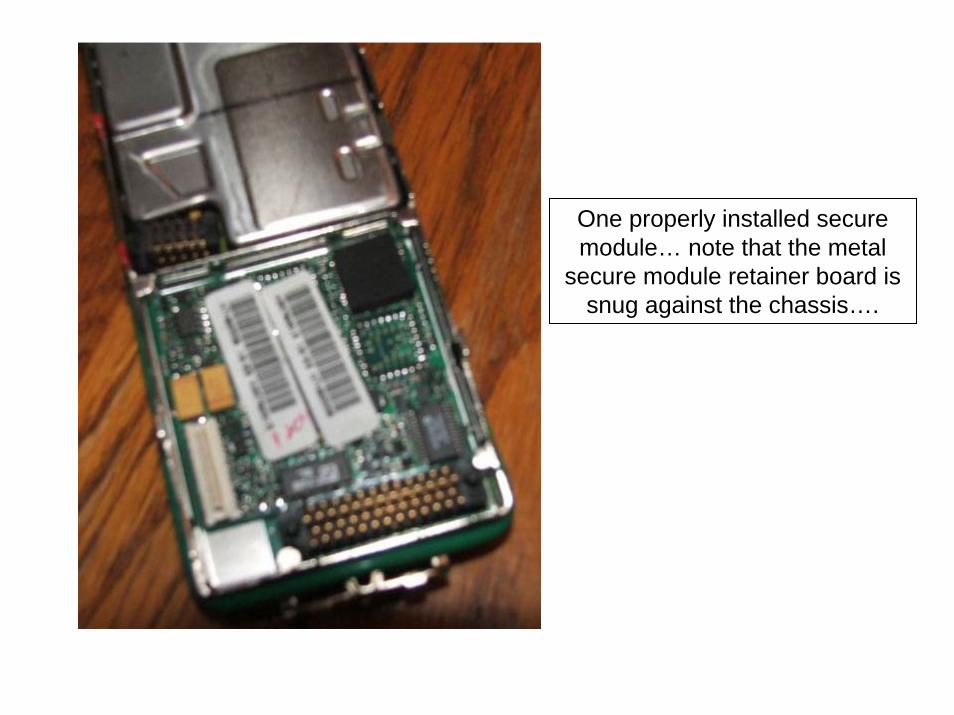
One properly installed secure module… note that the metal
secure module retainer board is snug against the chassis….
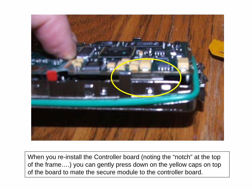
When you re-install the Controller board (noting the “notch” at the top of the frame….) you can gently press down on the yellow caps on top of the board to mate the secure module to the controller board.

The Idiot Check
Once you have the controller board mated to the secure module and properly reseated into the chassis, check to make sure you can see
the posts on the header connectors sticking through their corresponding holes in the board. This is your last chance before final assembly to correct an incorrectly seated header connector!

Install the keypad flex and shield assembly…there are four retainers that must engage the chasiss….
Then engage the Keypad flex retainer….
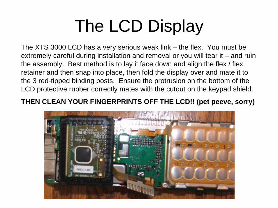
The LCD DisplayThe XTS 3000 LCD has a very serious weak link – the flex. You must be extremely careful during installation and removal or you will tear it – and ruin the assembly. Best method is to lay it face down and align the flex / flex retainer and then snap into place, then fold the display over and mate it to the 3 red-tipped binding posts. Ensure the protrusion on the bottom of the LCD protective rubber correctly mates with the cutout on the keypad shield.
THEN CLEAN YOUR FINGERPRINTS OFF THE LCD!! (pet peeve, sorry)

LOOK MOM! My o-ring isn’t torn up!
Note the rubber tit at the bottom of the LCD is engaged in the keypad flex shield and the “finger” is sticking out from the
display flex….

Insert the chassis into the top of the front shield…. The two upper metal tabs on the casting will slide UNDER the yellow lip below the MOTOROLA logo…..gently
keep pushing the casting upwards into the front shield….
Make sure the o-ring is properly seated along the left and right of the
frame and you’ll end up with the picture on the left here…. Ready for
the final “seat” into the case…

One trick that I’ve used is to turn the tool
around BACKWARDS and very gently pry the
case outward while simultaneously pushing
down on the radio chassis…. This makes the o-ring seat properly
EVERY TIME!

Note that the o-ring is NOT visible from the outside and that there is ZERO DAMAGE to the bottom of the front shield…. Done RIGHT!

And the final result…..

Those Damn KnobsThe frequency knob inserts on the 3000 and 5000 are *NOT* the same, neither is the
sticker that goes on the insert! Alas, you use the same technique to remove and install them. Here are some pictures that can help you with this task. I discourage you from reusing the inserts as they are very easily damaged… so easy that the first “test” I do when I examine a radio for purchase is to gently pull upwards on the channel select
(frequency) knob to see if it’s been swapped… you’d be amazed how many come off in your hands….The white plastic piece is commonly referred to as an “insert”…the manual
calls it an “insert retainer”. The volume insert is the same for both the 3000 and 5000.
Gently pry out the “fingers” from the insert and pry it off… takes a few tries….
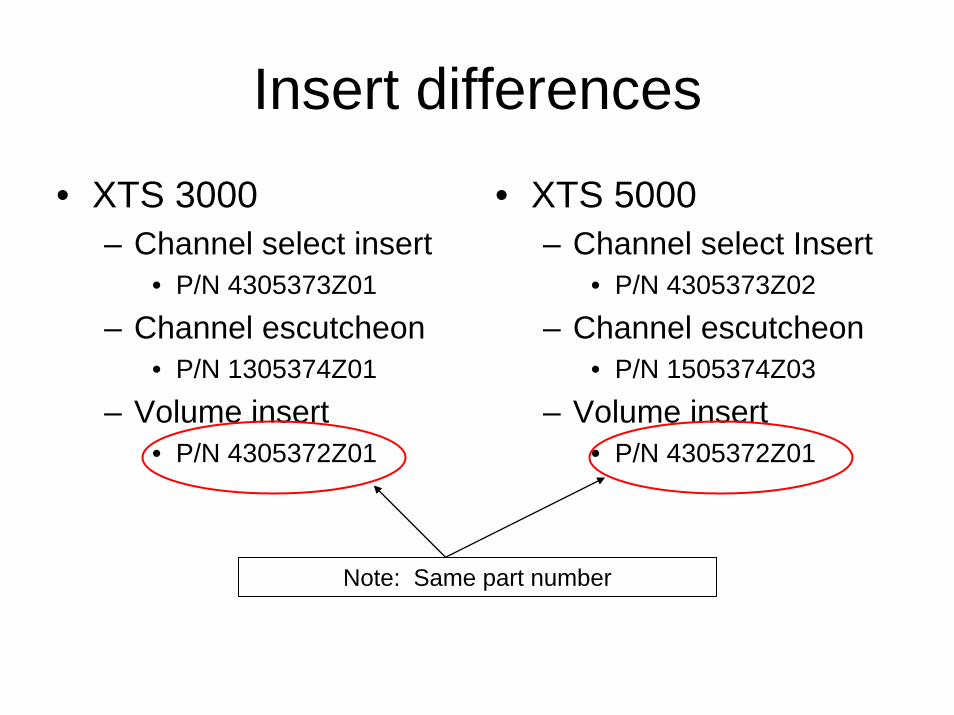
Insert differences
• XTS 3000– Channel select insert
• P/N 4305373Z01
– Channel escutcheon• P/N 1305374Z01
– Volume insert• P/N 4305372Z01
• XTS 5000– Channel select Insert
• P/N 4305373Z02
– Channel escutcheon• P/N 1505374Z03
– Volume insert• P/N 4305372Z01
Note: Same part number

Ok… some on the 5000The XTS 5000 is VERY similar, yet very different from the XTS 3000 series radios. It’s obvious from the internals that they learned some valuable lessons from the design of the 3000. Gone are the metal retainers that secure the LCD and keypad flex…. They’ve been replaced with high density connectors that are much easier to install and remove. One of the most glaring differences between the two radios is that the XTS 5000 only uses two circuit boards: the VOCON and the RF board. Gone is the XTS3000 vocoder board – it’s been completely incorporated into the VOCON. (VOcoder CONtroller = VOCON)
The removal of the front shield on the XTS 5000 is exactly the same as the XTS 3000. The special tool is the previously covered 6685833D01. The front shield flex plug from the housing to the VOCON is a little smaller on the 5000, but the technique of front shield removal is the same.

LCD flex plug
Front Shield flex plug
Keypad
flex plug

Nice shot of the LCD connector. The rubber locator pad surrounding the LCD is only secured on two posts on the 5000 – the 3000 uses three
posts…

This is the “old style” NTN4563 VOCON. It has been replaced with the NNTN4717 VOCON. It uses a different processor (RAM22 in self test) than
the NNTN4717 (BRAVO in self test) but is otherwise indifferent from the newer NNTN4717. Both boards have 8 megs of RAM and any differences
are completely transparent to the user.
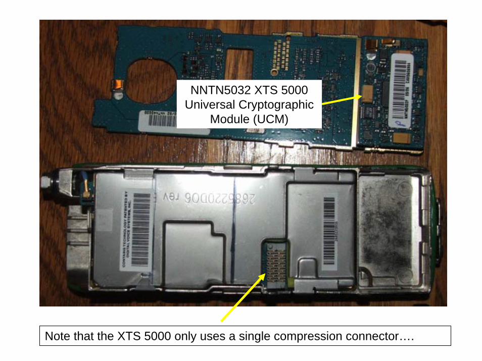
Note that the XTS 5000 only uses a single compression connector….
NNTN5032 XTS 5000 Universal Cryptographic
Module (UCM)
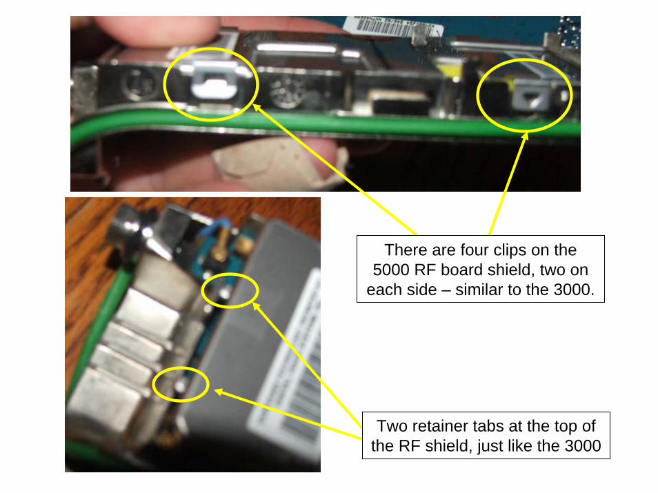
Two retainer tabs at the top of the RF shield, just like the 3000
There are four clips on the 5000 RF board shield, two on
each side – similar to the 3000.

This is a unique feature of the 5000 – there is a rubber pad on top of the RF board in between the actual circuit board and the RF shield. Note here the view of the keying lugs for the compression connector. The RF board is retained in a similar manner as the 3000, you have to lift the left side up to clear the tabs on the right hand side. This pad is band specific due to variations in the RF board components… there are yellow, green and orange ones depending on the RF
band of the board. When reinstalling the RF shield, you must ensure the board cutouts clear the notch provided for the compression connector – and that they
don’t ‘pinch’ this rubber mat.

This is the NTN8910 VHF XTS 5000 RF board. Note the same little blue cable connects the RF board to the RF connector on the chassis… BE CAREFUL!

This is the backside of the NTN4563 VOCON – showing the secure module and it’s mating socket on the rear of the board.

This is the best view I could get of the tab /
notch at the top of the VOCON. This is very
similar to the XTS 3000 in that it serves to
secure the top of the VOCON to the chassis.

This is my technique for installing the
front shield onto the chasis. The rubber pad on the back of the
housing connector flex is
sitting at the bottom of my thumb. When you grab the
chassis with your other hand, it
makes it a cinch to mate the connector.

The remainder of the reassembly is the same as the 3000 – the same methods can be applied and you’ll enjoy a nice looking, undamaged case. In
the next few slides, I’ll explain some of the intricacies of the XTS 5000.
VHF UHF R1 UHF R2 700/800 DisplayPart #
NTN4563 X
XX
7285726C02
NTN4819 X 7285726C03
NTN9564 7285726C01
NNTN4717 X X X 7285726C02 (VHF/800)7285726C03 (UHF)
VOCODER and Display Compatibility Chart
The NNTN4717 is the newest VOCON and is usable on ANY band
The NTN9564 is unique in that it uses a different display – the “C01”– it will NOT function with anything other than a “C01” display.

The Astro Digital SaberI first held one of these radios in the spring of 1996, over 10 years ago. What a wonder of modern technology! Of course, at the time, no one outside Motorola really knew the plans for the platform – and VSELP ruled the day. Holding a radio with Host firmware of AP_R1.00.00 was pretty darn cool. The first generation mixed mode portable from Motorola (analog/VSELP), it was quite the brick to carry around, but between the display (14 characters!) and the channel capacity (255!) – not to mention the advent of the “S-record” and “LA_ROVER”…. What a radio!
Just think of the pride walking around the hamfest with an AS3 on your belt! Nothing but geek envy from those Systems Saber guys!
I’ll have to be honest. I don’t like taking Astro Sabers apart. Most tend to have brittle flexes on the display board and side of the frame (PTT/Monitor buttons), so please proceed at your own risk. You’ll note in the slides the common errors I’ve seen from radios I’ve encountered in the field.

The Astro Digital Saber, Model 3, VHF with the new HNN9033 Impres battery
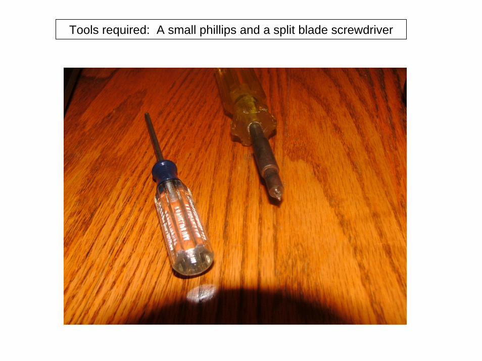
Tools required: A small phillips and a split blade screwdriver

Step 1: Remove the accessory/programming port cover…
Step 2: Loosen the two slotted screws at the bottom… no need to remove the belt clip….

Screw the antenna onto the radio and gently pull it out of the housing….


Contrary to popular belief, you do NOT need to pry on the two retainer tabs at the bottom of the front shield…. Just put your thumb where the yellow “X” is in the picture and push forward towards the top of the radio (horizontally) and the two plastic tabs will release…. This is why most second hand radios have broken plastic retainers… from guys who think you have to pry those two tabs off with a screwdriver…. Note that broken tabs do not really cause any problems – the radio is held together by compression anyway.
Plastic retainers
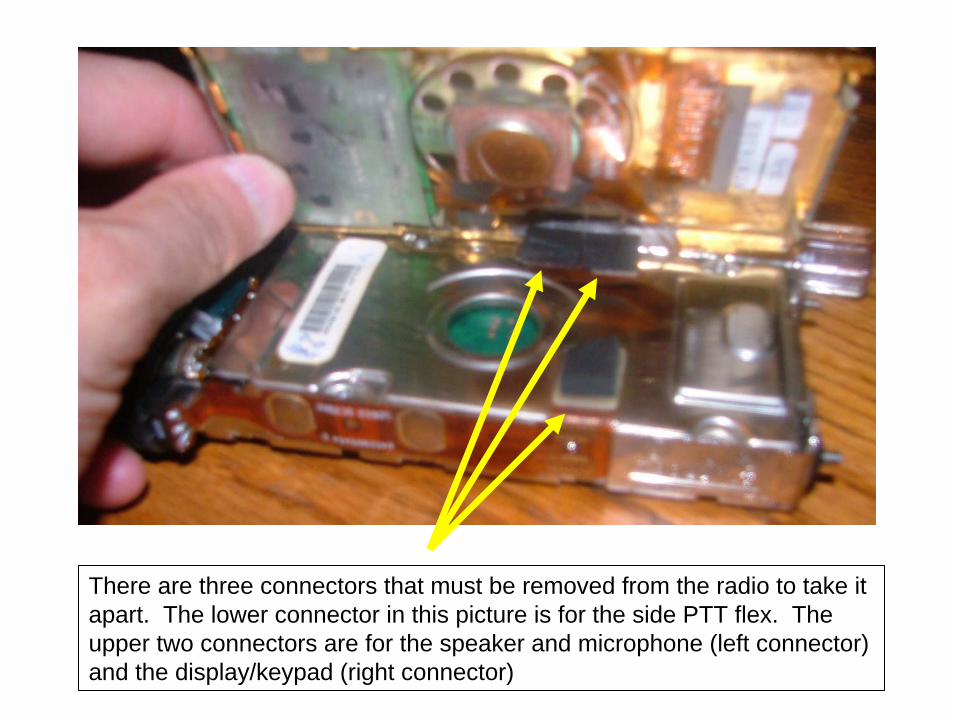
There are three connectors that must be removed from the radio to take it apart. The lower connector in this picture is for the side PTT flex. The upper two connectors are for the speaker and microphone (left connector) and the display/keypad (right connector)

Front shield separated from the chassis

RF board flex removal, gently pry upwards and it pops right off.

Now the fun part. You have to remove four little phillips screws to get the vocon out of the chassis. These are very easy to strip the screwheads
out of – so please be careful and use a proper fitting screwdriver…. They are also easily lost – so put them in a plastic cup! It’s very common to
find used radios missing one or two of these screws!

Once you get the screws out of the vocon carrier, this is what you are left with. A front cover, a rear cover and the vocon itself.

Pay attention how the two halves of the vocon shield fit together.

The biggest Achilles heel of the Astro Saber – the damn interconnect.

Vocon removed, RF board shield still in place.
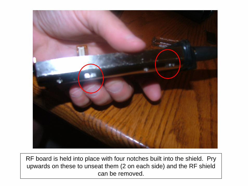
RF board is held into place with four notches built into the shield. Pry upwards on these to unseat them (2 on each side) and the RF shield
can be removed.

Sorry for the crappy pic guys – but this is the Astro Saber RF board and secure module. The secure module is retained by metal fingers in the chassis – it snaps into place securely… sometimes you’ll see these
second hand either without the secure module metal “can” – or not snapped into place correctly.

Notice something funny about this header connector?
Laugh now young Jedi. I actually bought a “DOA” Astro Saber on ebaywith it’s header connector installed this way… guess what? When I
fixed the header orientation… it worked JUST FINE! Ha!

The radio can now be reassembled using the reverse of the disassembly instructions. Pay close attention to that header
connector – it’s easy to bend the pins on it when it mates with the vocon. Make sure all four of the small vocon retainer screws are installed correctly. BE VERY CAREFUL WITH THE CONTROL
FLEXES. Most of these radios are around 6-8 years old now – bend one of those flexes the wrong direction and you will find yourself on MOL trying to order new parts for your toy…. And just wait until you
see how much parts cost for one of these babies!
(sucks to be you….)
Anyway, this concludes the Astro portable series of tips and tricks –I’m sure some sharp guy out there will want something added… feel
free to PM me on batlabs and I’ll edit/fix as required.

Your comments always appreciated… and don’t forget to visit…..
http://batboard.batlabs.com