Double-Tuned Impedance Matching - ARL ASSOCIATESWheeler’s double-tuned impedance matching...
15
Double-Tuned Impedance Matching Alfred R. Lopez, Life Fellow, IEEE ARL Associates 4 Sarina Drive Commack, NY 11725 Tel: 631 499 2987 Fax: 631 462 0320 Cell: 631 357 9342 Email: [email protected] Keywords: Impedance matching, Wheeler matching, Fano matching, Narrow bandwidth, Fractional bandwidth, Smith chart, Reflection chart, Impedance charts, Carter chart, Bode-Fano Criterion Abstract Harold Wheeler, in the 1940s developed, in a simple form, the principles of double-tuned impedance matching. These relationships are not well known. They are very useful for the antenna designer in providing a structured approach to obtain near maximum bandwidth for narrowband and moderate-band antennas with a specified VSWR limit using a practical arrangement of tuning elements. Wheeler first developed relationships for single-tuned impedance matching, which relate the fractional bandwidth to the antenna Q and the maximum permissible reflection-coefficient magnitude (or VSWR). He used the results of single-tuned impedance matching to derive the relationship for double-tuned impedance matching. Wheeler’s double-tuned impedance matching relationship is the best overall measure of the achievable fractional bandwidth for an antenna. Double tuning is practical and provides more than double the fractional bandwidth of single-tuned impedance matching. One example of double-tuned impedance matching is presented. A comparison to recently published results for single-tuned impedance matching verifies that double tuning more than doubles the fractional bandwidth of single-tuned impedance matching. 1. Introduction It is believed that it was Wheeler [1,2] who first introduced the concept of double- tuned impedance matching. He started by first defining two types of single-tuned impedance matching. The antenna was assumed to be a capacitor or inductor with constant radiation resistance. If the antenna was a capacitor in series with a resistance, he used an inductor in series with the capacitor to resonate the
-
Upload
vuonghuong -
Category
Documents
-
view
234 -
download
2
Transcript of Double-Tuned Impedance Matching - ARL ASSOCIATESWheeler’s double-tuned impedance matching...

Double-Tuned Impedance Matching Alfred R. Lopez, Life Fellow, IEEE ARL Associates 4 Sarina Drive Commack, NY 11725 Tel: 631 499 2987 Fax: 631 462 0320 Cell: 631 357 9342 Email: [email protected] Keywords: Impedance matching, Wheeler matching, Fano matching, Narrow bandwidth, Fractional bandwidth, Smith chart, Reflection chart, Impedance charts, Carter chart, Bode-Fano Criterion Abstract Harold Wheeler, in the 1940s developed, in a simple form, the principles of double-tuned impedance matching. These relationships are not well known. They are very useful for the antenna designer in providing a structured approach to obtain near maximum bandwidth for narrowband and moderate-band antennas with a specified VSWR limit using a practical arrangement of tuning elements. Wheeler first developed relationships for single-tuned impedance matching, which relate the fractional bandwidth to the antenna Q and the maximum permissible reflection-coefficient magnitude (or VSWR). He used the results of single-tuned impedance matching to derive the relationship for double-tuned impedance matching. Wheeler’s double-tuned impedance matching relationship is the best overall measure of the achievable fractional bandwidth for an antenna. Double tuning is practical and provides more than double the fractional bandwidth of single-tuned impedance matching. One example of double-tuned impedance matching is presented. A comparison to recently published results for single-tuned impedance matching verifies that double tuning more than doubles the fractional bandwidth of single-tuned impedance matching. 1. Introduction It is believed that it was Wheeler [1,2] who first introduced the concept of double-tuned impedance matching. He started by first defining two types of single-tuned impedance matching. The antenna was assumed to be a capacitor or inductor with constant radiation resistance. If the antenna was a capacitor in series with a resistance, he used an inductor in series with the capacitor to resonate the

antenna, and if needed, an impedance transformer to achieve impedance match (zero reflection) at the resonant frequency. He referred to this case as “single-tuned mid-band matching”. For best matching over a frequency band the maximum reflection-coefficient magnitude or the maximum VSWR is specified. For this case Wheeler introduced mismatch at the resonant frequency to achieve the mismatch limit at the edge-band frequencies [2, Fig. 6], [3, Fig. 2]. He referred to this case as “single-tuned edge-band matching”. For a 2:1 VSWR limit, edge-band matching provides a 6% increase in bandwidth over mid-band matching. Edge-band matching provides the highest possible fractional bandwidth for single-tuned impedance matching. Double-tuned impedance matching was defined directly from the single-tuned edge-band matching case. For the series tuned circuit described above a parallel resonant circuit was added to double-tune the antenna such that the edge-band frequency points are coincident on the zero-reactance line. Simple geometrical proofs, using the reflection chart, showed that the reflection-coefficient magnitudes for the low, mid and high frequencies are the same, are maximum values, and that the maximum reflection-coefficient magnitude for the double-tuned case is equal to the square of the maximum reflection-coefficient magnitude for the single-tuned edge-band matched case. Wheeler’s work produced three equations [3]:
Single-Tuned Mid-Band Matching
S
1S
Q
1
1
2
Q
1B
2MB1
(1)
Single-Tuned Edge-Band Matching
S2
1S
Q
1
1
2
Q
1B
2
2EB1
(2)
Double-Tuned Matching
1SQ
1
1
2
Q
1B 2
2
(3)
Where
0
LowHigh
LowHigh
LowHigh
f
ff
ff
ff Bandwidth Fractional B
(For a given antenna Q, B is the bandwidth over which a specified reflection-coefficient magnitude (or VSWR) is not exceeded.) f0 = Resonant Frequency Q = Antenna Quality Factor (In general, includes dissipative loss) Γ = Maximum Reflection Coefficient Magnitude S = Maximum VSWR
31.2B
B ,45.2
B
B 2, S For
1EB
2
1MB
2

2B
BLim
EB1
2S
Double-tuning more than doubles the single-tuning bandwidth. Wheeler pointed out [2] that even though the above results were derived for an electrically small antenna (capacitor or inductor with constant resistance) they also apply to larger antennas such as a wavelength dipole. The general double-tuning principles that apply to all antennas are:
1. The impedance locus encircles the center of the reflection chart 2. The edge-band frequencies and an intermediate frequency (at or near
resonance) are at the limit of the permissible reflection-coefficient magnitude (or VSWR) and lie on a straight line that passes through the center of the reflection chart
This paper presents one example of double-tuned impedance matching. The selected antenna is the spherical-cap dipole with ka = 0.450 at 300 MHz (1/k = λ/2π = radian length, a = radius of sphere that circumscribes the antenna). This antenna was selected so that the results could be compared to recently published results for single-tuned mid-band impedance matching [4, Table 4]. The purpose of this paper is to highlight the double-tuned impedance-matching concept and to demonstrate, by means of an example, the substantial bandwidth increase of double tuning over single tuning. The emphasis here is the theoretical quantification of the impedance-matching bandwidth as limited by the Q of the antenna and the maximum permissible reflection coefficient magnitude. Equation (3) above defines this relationship. Double-tuned impedance matching should not be confused with other impedance matching techniques, such as double-stub impedance matching [5], which are techniques for matching an arbitrary load at a single frequency, and are, essentially, single-tuned designs. Double-tuned impedance matching is a member of a family of multiple-tuned circuits that provides, in theory, the highest possible impedance-matching bandwidth for narrow and moderate bandwidth applications. The distinguishing feature of this family is that it is designed for impedance matching of an inductance-resistance or capacitance-conductance load over the widest possible bandwidth, consistent with the limitations imposed by the complexity of the matching network, the Q of the load, and the permissible reflection coefficient magnitude. This family was first described by Fano [6]. Although this article is based on the results of computer simulations the application of the principles to practical antennas has a long history. An early application of the double-tuned impedance matching principle to the design of an antenna is attributed to Wheeler [1]. His patent, issued in the 1940s, describes the details and the performance of what was called the “Lifesaver Antenna.” This antenna design utilized the double-tuned impedance matching principle. During
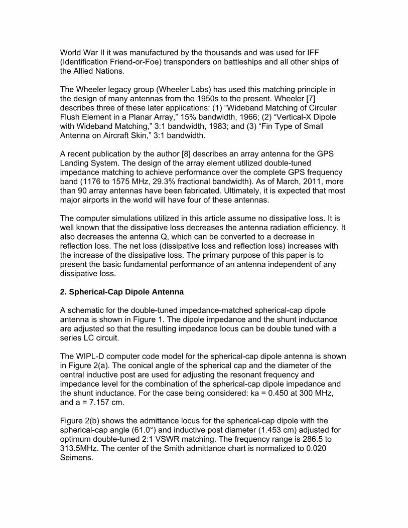
World War II it was manufactured by the thousands and was used for IFF (Identification Friend-or-Foe) transponders on battleships and all other ships of the Allied Nations. The Wheeler legacy group (Wheeler Labs) has used this matching principle in the design of many antennas from the 1950s to the present. Wheeler [7] describes three of these later applications: (1) “Wideband Matching of Circular Flush Element in a Planar Array,” 15% bandwidth, 1966; (2) “Vertical-X Dipole with Wideband Matching,” 3:1 bandwidth, 1983; and (3) “Fin Type of Small Antenna on Aircraft Skin,” 3:1 bandwidth. A recent publication by the author [8] describes an array antenna for the GPS Landing System. The design of the array element utilized double-tuned impedance matching to achieve performance over the complete GPS frequency band (1176 to 1575 MHz, 29.3% fractional bandwidth). As of March, 2011, more than 90 array antennas have been fabricated. Ultimately, it is expected that most major airports in the world will have four of these antennas. The computer simulations utilized in this article assume no dissipative loss. It is well known that the dissipative loss decreases the antenna radiation efficiency. It also decreases the antenna Q, which can be converted to a decrease in reflection loss. The net loss (dissipative loss and reflection loss) increases with the increase of the dissipative loss. The primary purpose of this paper is to present the basic fundamental performance of an antenna independent of any dissipative loss. 2. Spherical-Cap Dipole Antenna A schematic for the double-tuned impedance-matched spherical-cap dipole antenna is shown in Figure 1. The dipole impedance and the shunt inductance are adjusted so that the resulting impedance locus can be double tuned with a series LC circuit.
The WIPL-D computer code model for the spherical-cap dipole antenna is shown in Figure 2(a). The conical angle of the spherical cap and the diameter of the central inductive post are used for adjusting the resonant frequency and impedance level for the combination of the spherical-cap dipole impedance and the shunt inductance. For the case being considered: ka = 0.450 at 300 MHz, and a = 7.157 cm. Figure 2(b) shows the admittance locus for the spherical-cap dipole with the spherical-cap angle (61.0°) and inductive post diameter (1.453 cm) adjusted for optimum double-tuned 2:1 VSWR matching. The frequency range is 286.5 to 313.5MHz. The center of the Smith admittance chart is normalized to 0.020 Seimens.

It is noted that in Figure 2(b) that the Smith Admittance Chart is used. This chart is helpful in adjusting the dipole dimensions so that the admittance locus is properly positioned between the 0.0040 and the 0.040 Siemens circles, so that the shunt inductance properly positions the impedance locus (Fig. 3(b)) for final double tuning with a series resonant circuit. (Also later, in Figures 4(a) and 5(a), a simple reflection (polar) chart is used to show that the impedance-matching design objective, maintaining the reflection magnitude within the VSWR = 2 (= 0.33) circle, is achieved.) [Historical note: In the 1950s Harold Wheeler developed an impedance-matching technique that utilized a slotted line and a set of overlaying impedance charts. The top chart was a transparent reflection (polar) chart and the bottom chart was either a Smith impedance chart, a Smith admittance chart, or a Carter impedance chart (constant-impedance amplitude and phase lines, used for impedance transformation). The overlay charts were useful for developing an impedance matching strategy and for determining the characteristics of the matching components.] 3. Spherical-Cap Dipole Antenna with Shunt L The WIPL-D computer code model for the spherical-cap dipole antenna with shunt inductance across the feed gap is shown in Figure 3(a). The shunt inductance (0.01326 μH) is selected so that the low and high frequencies impedance points lie on the constant 25 Ohm resistance circle of the Smith impedance chart as shown in Figure 3(b). The impedance locus is tangent to the constant 100 Ohm resistance circle at a frequency near 300 MHz. The combination of the spherical-cap dipole and shunt L act as a parallel resonant circuit that can be double tuned with a series resonant circuit. The key geometrical consideration for this impedance matching approach is shown in Figure 3(b). It should be apparent that for the series resonant circuit the right combination of resonant frequency and reactance will make the low and high frequencies points coincident at a desired location on the constant 25 Ohm resistance circle, which, for the case being considered, is located slightly above the resistive axis. 4. Spherical-Cap Dipole Antenna with Shunt L and Series LC For the final step in double-tuned impedance matching a series inductance-capacitance circuit is located at the input port of the matching network for the WIPL-D configuration of Figure 3(a). The resonant frequency for the series LC circuit is set to 308.5 MHz (which is different than the 301 MHz resonant frequency of the dipole with shunt inductance combination shown in Figure 3(b)). The series inductance = 0.2373 μH, and the series capacitance = 1.1215 pF. This combination results in the double-tuned reflection locus shown in Figure

4(a). Figure 4(b) presents VSWR versus frequency. The 2:1 VSWR fractional bandwidth = 9.01% 5. Single-Tuned Mid-band Matched Spherical-Cap Dipole Antenna For comparison purposes the impedance matching performance of the single-tuned mid-band matched spherical-cap dipole antenna was computed. Single-tuned mid-band matching was achieved using the WIPL-D configuration shown in Figure 3(a). The diameter of the dipole post was reduced to 1.220 cm and the shunt inductance was set = 0.0100 H. The reflection chart and the VSWR are presented in Figure 5. The single-tuned mid-band matched 2:1 VSWR fractional bandwidth = 3.73% Figure 5 shows the substantial increase of the fractional bandwidth provided by double-tuned matching as compared to that of single-tuned matching 6. Comparison to Previously Published Results A comparison of the performance achieved in this paper to that achieved in [4] is presented in Table 1. Table 1. Performance comparison for impedance matching of spherical-cap dipole antenna
Impedance Matching Type Single-Tuned Mid-band Match
Double Tuned
(WIPL-D) WIPL-D Ref. [4] Antenna Spherical-Cap Dipole 1
ka at 300 MHz 0.450 2:1 VSWR
Fractional Bandwidth (%) B2 = 9.01
(Figure 4(b)) B1MB = 3.73 (Figure 5(b))
B1MB =3.52 2
Q 19.2 3 19.0 4 19.5 QLB
5 13.2 Q/QLB 1.45 1.44 1.48
B2/B1MB Ratio (Theoretical, Eqs. (1)(3))
2.42 (2.45)
Notes: 1. WIPL-D computer code assumes no dissipative loss 2. See [4, Table 4]
3. The equation, 2
2
B
1SQ
, was used to compute an effective Q
4. The equation, SB
1SQ
MB1
, was used to compute an effective Q
5. 23LB )ka(1
)ka(
1Q = Lower bound on Q [4]

It is observed that the 2:1 VSWR fractional bandwidth and the Q for the single-tuned mid-band matched WIPL-D and Ref. [4] results are in good agreement. What is especially noteworthy is the excellent agreement of the B2/B1MB ratio for the WIPL-D code results and the theoretical results using Equations (1) and (3). This demonstrates the excellent results that can be achieved with modern computer-aided antenna design tools. The results presented in Table 1 provide substantiation that double-tuned impedance matching more than doubles the matching bandwidth achieved with single-tuned impedance matching 7. Multiple-Tuned Impedance Matching Fano [6] established the theoretical limit on the matching bandwidth with respect to the number of tuned circuits in the impedance matching network. Using the same Wheeler antenna model (capacitor or inductor with constant radiation resistance), Fano derived an exact relationship for Bn, Q, and Γ, where n = 1, 2, 3, 4, …….., ∞, is the number of tuned circuits in the matching network. (Single tuned, n = 1; Double tuned, n = 2; Triple-tuned, n = 3, etc.). Wheeler’s equations for single-tuned edge-band and double-tuned matching are in exact agreement with Fano’s equations for single and double tuning [3]. Fano’s solution is a set of three simultaneous transcendental equations that relate Bn, Q, and Γ [9]. Table 2 presents the results of an evaluation [9] of Fano’s equations to determine the increase in the fractional bandwidth with a unit step in the tuning level. Table 2. Fractional-bandwidth ratio increase with increasing n, VSWR = 2:1
n Bn/Bn-1 Ratio (Percent Increase)
2 2.309 (130.9) 3 1.238 (23.8) 4 1.100 (10.0) 5 1.043 (4.3) 6 1.032 (3.2) 7 1.022 (2.2) 8 1.015 (1.5)
It is observed that the ratio rapidly decreases for n > 2. Wheeler [2] states: “Only double or triple tuning is likely to be justified in practice. With practical tolerances on the added reactance arms, there is an optimum number of added tunings, such that a greater number would increase the reflection ratio by their tolerances more than they would decrease it by the theory.” Wheeler established a guideline for a practical upper bound on the fractional bandwidth Fano’s theoretical upper bound on the fractional bandwidth corresponds to the case of n = ∞. For this case the fractional bandwidth is given by [9]:

1S
1Sln
Q
1
1ln
Q
1B (4)
Bode [10, p. 367] was the first to publish the underlying principles for this result. Pozar [5, pp. 261-263] presents an overview on “The Bode-Fano Criterion.” Equation (4) is derived from Bode’s Equation (16-16) by converting his bandwidth to a fractional bandwidth. Obviously, Equation (4) (n = ∞) is not realizable in practice. Table 3 presents the percentage of the theoretical upper bound achieved with multiple-tuned impedance matching. Table 3. Percent of theoretical upper-bound fractional bandwidth for multiple-tuned matching, VSWR = 2
n Bn/B∞ (Percent)
1 26.2 2 60.6 3 75.0 4 82.5 5 86.9 6 89.7 7 91.7 8 93.1
Double tuning (n = 2) provides most of the fractional bandwidth of the theoretical limit for multiple-tuned impedance matching. Conservatively, we can use double tuning, Equation (3), as the practical upper bound on the bandwidth. 8. Upper Bound on Impedance-Matching Bandwidth Best and Hanna [4] in Section 2, “Fundamental Limitations on Q and Bandwidth,”
state that their Equation (6), s
1s
Q
1FBW
lbVub
, is “an upper bound on the
fractional matched VSWR bandwidth.” The bound applies to their fractional matched VSWR bandwidth case, which is equivalent to the Wheeler single-tuned mid-band matching case. The fundamental limitation on impedance-matching bandwidth is the upper bound on the fractional bandwidth independent of any specific matching network, and for a given Q and a specified S. As noted above, such a bound was quantified by Bode and Fano:

Theoretical:
1S
1Sln
Q
1BTUB (5)
As is typical of theoretical bounds, it is not achievable in practice. As noted above, double-tuned matching can be used as a conservative practical upper bound on the fractional bandwidth.
Practical: 1SQ
1B 2
PUB (6)
9. Summary Wheeler’s principles of double-tuned impedance matching are not well known. He developed relationships for single-tuned mid-band and single-tuned edge-band impedance matching, which relate the bandwidth to the antenna Q and the maximum permissible reflection magnitude (or VSWR). He used the results of single-tuned edge-band impedance matching for a simple derivation of the relationship for double-tuned impedance matching.
Wheeler’s double-tuned impedance matching equation, 1SQ
1B 2
2 , is
perhaps the best overall measure of the achievable bandwidth for an antenna with a limit on the maximum VSWR. Double tuning is practical, provides more than double the bandwidth of single-tuned impedance matching, and more than 60% of the theoretical upper bound on the impedance-matching bandwidth. B2 can be considered as a practical upper bound on the impedance-matching bandwidth. One example of a double-tuned impedance matching network was presented here in detail. A comparison to recently published results for single-tuned mid-band impedance matching verifies that double tuning more than doubles the bandwidth of single-tuned impedance matching. The double-tuned impedance matching technique was historically derived based on the approximation that the antenna was an electrically small antenna, a lumped capacitor or inductor with radiation resistance assumed to be constant over the bandwidth of interest. However, the fact is that the double-tuned approach can be usefully applied to antennas that are not electrically small, and have bandwidths that exceed 2:1. 10. Acknowledgements Many thanks are given to Peter W. Hannan for his critical review of the manuscript. 11. References

[1] H. A. Wheeler, U.S. Patent 2,425,585, “Wave-Signal Antenna (Hazeltine Double-Tuned Lifesaver Antenna),” Issued: Aug. 12, 1947, Filed: Dec. 13, 1943 http://www.google.com/patents/about?id=6wRbAAAAEBAJ&dq=2425585 [2] H. A. Wheeler, “Wideband Impedance Matching,” Wheeler Laboratories Report 418, May 1950 http://www.arlassociates.net/May1950wheelerreport418.pdf [3] A. R. Lopez, “Wheeler and Fano Impedance Matching,” IEEE Antennas and Propagation Magazine, Vol. 49, No. 4, pp. 116-119, August 2007 http://www.arlassociates.net/wheeler&fanozmatching.pdf [4] S. R. Best, D. L. Hanna, “A Performance Comparison of Fundamental Small-Antenna Designs,” IEEE Antennas and Propagation Magazine, Vol. 52, No. 1, pp. 47-70, February 2010 [5] D. M. Pozar, Microwave Engineering, Third Edition, Hoboken, N.J., Wiley, pp. 261-263, 2005 [6] R. M. Fano, “Theoretical Limitations on the Broadband Matching of Arbitrary Impedances,” Journal of the Franklin Institute, Vol. 249, No. 1, pp. 57-83, January 1950, No. 2, pp. 139-154, February 1950 [7] H. A. Wheeler, “Antenna Topics in My Experience,” IEEE Transactions on Antennas and Propagation, Vol. AP-33, No. 2, pp.144-151, February 1985 [8] A. R. Lopez, “GPS Landing System Reference Antenna,” IEEE Antennas and Propagation Magazine, Vol. 52, No. 1, February 2010, pp. 104-113 http://www.arlassociates.net/2010GPSReferenceAntenna.pdf [9] A. R. Lopez, “Review of Narrowband Impedance-Matching Limitations,” IEEE Antennas and Propagation Magazine, Vol. 46, No. 4, August 2004, pp. 88-90 http://www.arlassociates.net/Lopez2004PaperFanoMatching.pdf [10] H. W. Bode, Network Analysis and Feedback Amplifier Design, Princeton N.J., Van Nostrand, p. 367, 1945

Spherical-Cap Dipole Antenna
Shunt L
Series LC
Input Port
Quasi Parallel Resonant Circuit
Figure 1. Schematic Diagram
Figure 1a. Basic WIPL Model

(a) WIPL-D model
(b) Smith Admittance Chart, normalized to 0.020 Siemens
Figure 2. Spherical-cap dipole antenna

(a) WIPL-D model
(b) Smith Impedance Chart, normalized to 50 Ohms
Figure 3. Spherical-cap dipole antenna with shunt inductance, L

(a) Reflection (Polar) Chart, 50 Ohms at center
(b) VSWR
Figure 4. Spherical-cap dipole antenna with shunt L and Series LC

(a) Reflection (Polar) Chart, 50 Ohms at center
(b) VSWR
Figure 5. Single-tuned mid-band matched spherical-cap dipole antenna