Double Track Lift Bridge - Custom Model Railroads...
19
Double Track Lift Bridge 5"W x 28.75"L x 13.5"H Plus two 9" long approach bridges Instructions for assembly of the Double Track Lift Bridge Included in this kit: Instructions and part diagrams 136ea. 1/16" laser cut loose parts 11ea. 1/16" laser cut parts sheets 4ea. 1/8" laser cut parts 1ea. 1/16" square rod 7ea 3/64" x 15" plastic coated wire A vertical lift bridge has a span which rises vertically while remaining parallel with the track. The counterweights on a vertical lift bridge only have to be equal to the weight of the bridge, whereas on a bascule bridge counterweights must weigh several times more than the span being lifted. Therefore, heavier materials can be used on the deck of the lift bridge which makes it especially well suited for heavy railroad use. Our bridge is based upon typical lift bridges found in the United States spanning the Mississippi and other major rivers. These were built from the early 1900’s on. Our model has a 115 foot long lift span and towers that rise 75 feet. The entire bridge is raised on concrete piers and has unique footings. In addition to the lift bridge, the kit includes two 65’ long girder bridges which may be used as approaches to the main bridge. This is a non operating model. Please read these instructions completely before beginning and take your time to become familiar with the parts. Allow parts to dry after painting or gluing and do not try to build this in one night. This is a big bridge and it will take a little time to build. Drawings of all the parts have been included for ease of part identification. In order to make the instructions and figures clear, some of the model assemblies have been painted gray prior to photographing. In some cases the model is gray and the newly added parts have been left white. This is only for illustration purposes. You should paint your model as indicated in the instructions. Practice gluing the acrylic together if you have never done it before. There is plenty of scrap in your kit that you can use for this. See “Gluing Acrylic” for more information on this. If by chance a part is missing or broken, please write us indicating the kit name and part number and we will send you a replacement. You will need the following items to assemble your model: hobby knife, paint, paint brushes, glue, modeling putty, tweezers, files and sanding block.
Transcript of Double Track Lift Bridge - Custom Model Railroads...

Double Track Lift Bridge
5"W x 28.75"L x 13.5"H Plus two 9" long approach bridges
Instructions for assembly of the DoubleTrack Lift Bridge
Included in this kit:Instructions and part diagrams136ea. 1/16" laser cut loose parts11ea. 1/16" laser cut parts sheets4ea. 1/8" laser cut parts1ea. 1/16" square rod7ea 3/64" x 15" plastic coated wire
A vertical lift bridge has a span which rises vertically while remaining parallel with the track. The counterweights on a vertical lift bridge only have to be equal to the weight of the bridge,whereas on a bascule bridge counterweights must weigh several times more than the span beinglifted. Therefore, heavier materials can be used on the deck of the lift bridge which makes it especially well suited for heavy railroad use.
Our bridge is based upon typical lift bridges found in the United States spanning the Mississippiand other major rivers. These were built from the early 1900’s on. Our model has a 115 foot longlift span and towers that rise 75 feet. The entire bridge is raised on concrete piers and has uniquefootings. In addition to the lift bridge, the kit includes two 65’ long girder bridges which may beused as approaches to the main bridge. This is a non operating model.
Please read these instructions completely before beginning and take your time to become familiarwith the parts. Allow parts to dry after painting or gluing and do not try to build this in one night.This is a big bridge and it will take a little time to build. Drawings of all the parts have beenincluded for ease of part identification.
In order to make the instructions and figures clear, some of the model assemblies have beenpainted gray prior to photographing. In some cases the model is gray and the newly added partshave been left white. This is only for illustration purposes. You should paint your model asindicated in the instructions.
Practice gluing the acrylic together if you have never done it before. There is plenty of scrap inyour kit that you can use for this. See “Gluing Acrylic” for more information on this.
If by chance a part is missing or broken, please write us indicating the kit name and part numberand we will send you a replacement.
You will need the following items to assemble your model: hobby knife, paint, paint brushes,glue, modeling putty, tweezers, files and sanding block.

Gluing Acrylic
Always glue acrylic in a well-ventilated area, and read the glue manufacturer’s label forinstructions. We recommend using Tenax-7R by Hebco or Plastruct brand “Plastic Weld SolventCement” (PPC-2 or PPC-16) or “Bondine Solvent Cement”(Bond-2 or BOND-16). Tenax-7Rcomes with a dispenser and Plastruct sells a Solvent Syringe (HT-8 or HT-10) and various othersolvent dispensers. Most hobby shops carry these products or they may be ordered directly fromHebco (931)-796-7442 or Plastruct (626)-912-7016.
Acrylic must be glued together using a solvent that will melt the two edges and literally fusethem together. To do this, place the two pieces to be joined together and run a bead of solventdown the edge. Capillary action will suck the solvent into the joint and after several seconds thepieces will be fused. After only a few minutes the pieces will be strong enough to work with. Thebond will be completely dry within twenty four hours using the above-mentioned products.Solvent can be dispensed two ways.
Typically the solvent comes in a small bottle with a brush in the lid. The brush allows you todispense a drop or two of solvent at a time.
You may want to use a polyethylene bottle or syringe with a blunt needle dispenser. This allowslarger amounts of solvent to be dispensed quickly, accurately, and cleanly. Be sure the bottleyou are using is approved for the solvent you are using or you may melt through it. These may bepurchased from CMR.
Preparing Your Model for Painting
We recommend lightly sanding all parts to remove the raised edge created during the lasercutting process. In order to hide the seams we recommend using “hobbyist putty” such as GreenSquadron modeling putty. Do this in a very well ventilated area. Apply the putty over the seams;allow to dry overnight. Once the putty has dried, place a sheet of fine sandpaper on a flat surfaceand sand smooth. You may need to apply a second coat of putty and sand again.
Painting Your Model
We primed our model with Krylon Gray Primer spray paint. We used Krylon Flat Black spraypaint for the bridge. Krylon is available in most hardware stores. We also used “Polly ScaleAcrylics” for details and weathering, these are available in most hobby shops. Always testcompatibility of your paint with the acrylic by painting and testing a small area first.
We used Polly Scale Steam Power Black 414110 for touch up and weathering as well as thecables. The piers and counter weights were painted with Polly Scale Concrete 414317. Or youcan use Polly Scale Aged Concrete 414320. The walkways and railings we painted brown withPolly Scale D&RGW Building Brown 414256. We used Polly Scale Rust 414323 forweathering.
Never use alcohol or alcohol-based cleansers, paints or washes on acrylic. It will cause it to“shatter” and this is bad.

Bridge Truss Side Assembly
There are two bridge truss assemblies; build onefirst and then the other.
Lay the interior truss side (1) flat on your workspace. This is the truss side with the slots cut intoit. There are small engraved rectangles on one sideof the part that should be facing up.
Insert and glue two sets of the vertical supportbeams (3), (4), (5), (6) and (7) into the truss side(1). Use the tabs and slots to aid in position andalignment. See figure 1.
Glue two sets of the webbed truss braces (8), (9),(10), (11) and (12) to the truss side (1). Use theengraved lines on part (1) for alignment.See figure 2.
Glue the exterior truss side (2) to the assemblymaking sure that the side with the engraved rivetsis facing up. See figure 3.
Next glue the truss top (13) and bottom (14) inplace. See figure 3.
Note that the two vertical end beams, parts (3), onthe truss assembly are slightly taller than the rest. The truss top (13) is shorter than the truss bottom(14). Glue the truss top between the end verticalsupport beams (3) so that it lays flat across the topsof the rest of the support beams. It should sit insideof the truss sides so that it is flush with the top ofthe truss sides.
The bottom part (14) is slightly longer and runs theentire length of the truss. Glue this in place.
Fill the seams along the top and bottom with greensquadron modeling putty, allow to dry and sand orfile flush. See figure 4.
Now build the other truss assembly.
Figure 1
Figure 2
Figure 3
Figure 4

Bridge Base Assembly
Glue the cross braces (16) x 10 onto the beamsupports (15) x 4 using the slots for alignment.Make sure the assembly is square. See figure 5.
Glue the base top and bottom (17) x 2 onto thebeam support assembly. Make sure that the tabs onthe cross braces (16) stick out beyond the top. Testfit DO NOT GLUE the base assembly into the sidetruss assemblies in order to make sure that the tabsalign with the slots. See figure 6.
Bridge Assembly
Glue the two side assemblies to the base assemblymaking sure that all the tabs are seated properlyand that the assemblies are square to each other.Next glue two each of the top braces (18), (19),(20), (21), (22) between the side assemblies usingthe slots and tabs for alignment.
Glue the cable plates (62) x 2 (this is located on the hoist platform parts sheet) to the inside topedge of brace (18) on each end of the bridge. See figure 7.
Prime the bridge gray and paint it black.
Figure 5
Figure 6
Figure 7

Tower Assembly
The towers have side assembliessimilar to the bridge except that theyare not symmetrical. The sides willbe built in mirrored facing pairs. Asthere are two towers you will needto build two pairs.
Place the truss side part (23) onyour work table with the engravedside facing up. Glue part (27) intothe slots along the angled side ofpart (23). Glue part (28) into theslots along the straight side of part(23). Glue truss brace parts (30),(31), (32) and (33) into the slots on the cross braces of part (23). Glue webbed truss brace parts(34), (35), (36) and (37) onto part (23) using the engraved lines as guides.
Glue part (24) on top of the assembly with the engraved rivets facing up. Glue the guide rail part(29) into the slots on the face of part (24) (this is the side with only one set of slots). See figure 8.
Repeat the process for the other side using parts (25) and (26). This will make a mirroredassembly to the first one. See figure 9
Place the parts assembly (23), (24) so that the side with the slots is facing up. Glue part (38) intothe slot at the top of the assembly. Glue part (39) onto the angled side of the side of the assembly, glue part (40) onto the straight side of the side assembly. Glue part (41) into the slot atthe base of the assembly. See figure 10.
Glue the parts assembly (25), (26) to the other side to form a square tower. Make sure theassembly is square.
Figure 8
Figure 9
Figure 10

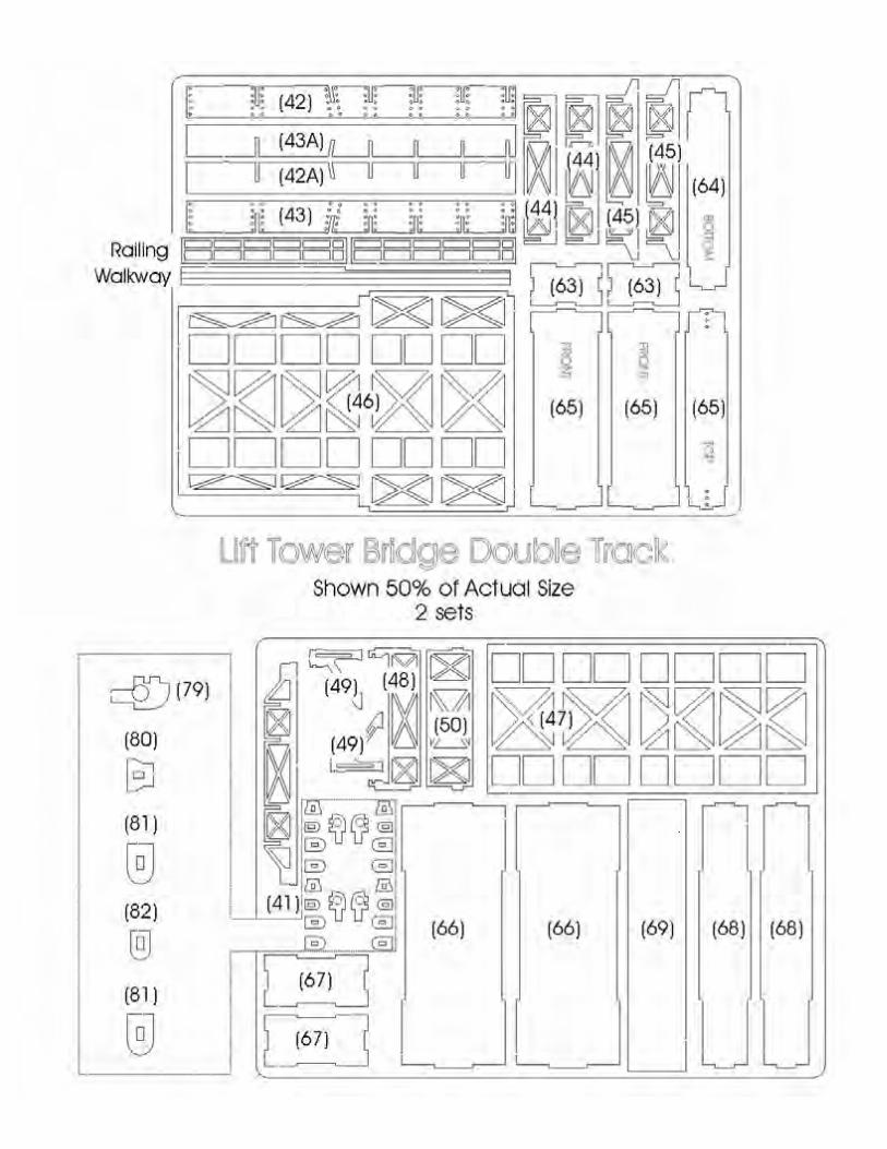
Attach the girders (42), (42A), (43A) and (43) tothe bottom of the tower using the slots foralignment. Note the orientation of the engravedrivets on (42) and (43). They should be facing out.Insert the cross braces (44) x 2 and (45) x 2 inalternating order. See figure 11.
Glue the top of the bridge webbing (46) to thegirders. Flip the assembly over and glue the bottomwebbing (47) to the underside of the bridge. Seefigure 12.
Assemble the bridge foot by gluing parts (48) and(50) between two parts (49). See Figure 13.
Glue the bridge foot to the end of the bridge towerbase. See figure 14.
Figure 15 shows the pair of towers completed. Onehas been primed while the other remains white.
Prime gray and paint the towers black.
Note: due to changes during the design processthere are no parts (51) or (52).
Figure 11
Figure 12
Figure 15
Figure 13
Figure 14

Hoist Platforms
There are two hoist platforms that are identical andsit on top of the towers. The platforms have largewheels which are used to hoist the bridge up anddown. The wheels have notches in them wherewire (representing the cables) will eventually beglued in place. On the front the wires will connectto the bridge, and on the back the wires will traveldown through the floor to the counterweights.
Glue the sides parts (53) x 2 and (54) x 2 to theplatform base (55) to form a box. The engravedside of part (55) should be facing up. Part (55) maybe curled due to the engraving. Use parts (54) toforce and hold it flat. Sand the parts after they havedried to remove any glue damage. Install the railing(56) and (57) x 2 into the holes in the platformbase. See figure 16.
Assemble the hoist wheels using four parts (58)and three parts (59). Stack the parts in alternatingorder beginning and ending with part (58). Use apiece of 1/16" square styrene rod as a shaft. Makesure that all of the wheel parts (59) are aligned inthe same manner (notches line up). Glue all theparts together. When dry, cut the square shaft sothat it extends 1/32” beyond the wheels. You willneed two of these for each tower. See figure 17.
Glue the wheel braces (60) x 4 into the base. Theside of the brace with the short bottom facestowards the front of the base (the side of the basewithout a railing). Glue the brace sides (61) x 4 tothe outside of the braces flush with the base.
Glue the wheels between the braces so that thenotches are facing down. The square rod shouldsnap into the holes in the wheel braces. Later wewill install wires (cables) from below and fit theminto the notches in the wheels. Repeat for the otherplatform. See Figure 18.
Glue the platforms onto the top of the towers. Thefront of the hoist platform should face the straight side of the tower. See Figure 19.
Prime gray and paint black.
Figure 16
Figure 17
Figure 18
Figure 19

Counterweights
There are two counterweights to assemble. Theseare basically cubes. The top has holes that thecables will slide into.
Glue the fronts (62) x 2 and the sides (63) x 2 tothe bottom (64). Glue the top (65) onto theassembly. Fill the edges with modelers putty andsand smooth using a sanding block. There shouldbe no visible seams when completed.See figure 20.
Prime gray and paint concrete color.
Bridge Piers
There are two types of bridge piers. The large ones are for the front of the towers and the smallerones are for the approach bridges. The parts are all tab and slot construction to help withalignment. The piers are basically cubes with a cap.You will need to build two of the large piers andfour of the small piers. When finished fill all theseams with modeling putty and sand smooth priorto attaching the caps.
Large Piers: Glue the fronts (66) x 2 and the sides(67) x 2 to the inside support parts (68) x 2 to forma cube. After filling and sanding glue the cap part(69) on top of the pier. See figure 21.
Small Piers: Glue the fronts (70) x 2 and the sides(71) x 2 to the inside supports (72) x 2 to form acube. After filling and sanding glue the cap part(73) on top of the pier. See figure 22.
Prime gray and paint concrete color.
Figure 20
Figure 21
Figure 22

Approach Bridges
Glue the cross braces (74) x 6 and (75) x 5 onto the beams (76) x 2 using the slots for alignment.The rivets on the beams should be facing out. Begin with a brace (74) on the end, then a (75)and so on, alternating every otherone. You should end with a brace(74) on each end. Make sure theassembly is square.
Glue the top (77) and bottom (78)onto the beam assembly.
Assemble the bridge feet by gluingparts (48) and (50) between parts(49) as done previously. Glue a footonto either end of the bridge. See figure 23.
Build two of the approach bridges.
Prime gray and paint black.
Bridge Guides
There are eight bridge guides to assemble. Theseare guides that keep the bridge on guide railsmounted on the towers. Begin by gluing part (80)onto part (79). Next stack part (81), (82) andanother (81) onto the pin on part (79) and glue inplace. See figure 24 for location and orientation ofthe parts.
Prime gray and paint black.
Figure 23
Figure 24

Final Bridge Assembly
At this point you should have all of the bridge components built. These include the lift bridge,two bridge towers, two approach bridges, two large piers, four small piers, two counterweightsand eight bridge guides.
We will begin by installing the counterweights in the bridge towers. You will be putting sixwires through six holes at the same time so some patience will be required.
Cut two of the 3/32" plastic coated wire into twelve equal pieces measuring 2.5". Sand off therough ends of the wire so that they are slightly pointed.
Insert the 2.5" wires into the holes in the tops ofthe counter weights and drop them all the way tothe bottom. This should leave 1.25" sticking up.Make sure that they are all parallel and square.Secure them in place with a drop of super glue.Double check they are still square and allow to dry.Once dry trim them flush if necessary and doublecheck for burrs on the exposed ends of the wires.Paint the wires black. Weather the concrete counterweight at this point as they will soon becomeinaccessible. See figure 25.
Slide the counterweight up into the bridge tower, run the six wires through the six holes in thehoist platform. The wires should fit into the notches in the hoist wheels. Glue in place with superglue while holding the weight so that the wires hang parallel to the flat side of the tower. Youmay need a second set of hands for this.
Alternatively you may lay the tower on the straightside and insert the counterweight. You can add ashim or block under the weight so that the wires areparallel to the flat side. Then glue the wires inplace to the hoist wheels. See Figure 26.
Repeat for the other tower.
Let dry completely. You may want to add someadditional super glue to where the cables meet thewheels to ensure that the glue joint is strong.
Figure 25
Figure 26

Next you will mount the bridge between thetowers. Glue the 1/8" acrylic bridge mounts (83) x 4 between the flanges of the “I” beams onthe ends of the bridge. The bridge mounts willstick out 1/16" of an inch from the flanges. See Figure 27.
Next glue the towers to the bridge. The bridgemounts attached to and extending from the bridgewill fit into the flanges on the towers. Assemble sothat the floor of the bridge and the towers areperfectly flush and glue together. See Figure 28.
Cut the remaining six pieces of plastic coated wireinto twelve lengths of 6". Sand the rough edges offof the ends of the wires. Paint the wires black. The wires mount into the notches on the front ofthe hoist wheels and into the holes on the top of the bridge cable plate (62). You may want to testfit them and trim to fit. Glue in place with super glue.
Install the bridge guides, there are two located on each side of the bridge top and bottom. Fit theguide over the guide rail (29) and glue in place. See Figure 28.
Place the lift bridge on the piers. The two large piers go under the tower. Two of the small piersgo under the ends of the tower bridges. These will be shared by the approach bridges. Theremaining two small piers go under the ends of the approach bridges. Of course yourarrangement can vary to suit your needs.
Figure 27
Figure 28

Install bridge track (not included in this kit), werecommend using Micro Engineering bridge track. This is available from your local hobby shop ordirect from Micro Engineering. Make sure it iscentered on the bridge. You will need to super gluethis to the bridge. You can use the walkways as astraight edge to push the track against in order tokeep it straight.
Paint the walkways and railings to resemble wood. Install the walk ways, as well as the railings alongside of the track. The exact location of this will depend upon the width of the bridge track ties.Also install the ladders on the ends of the towers, they should be on the same side as thewalkways.
You can weather your bridge with drips and runs of brown and rust, as well as an airbrushed overspray of gray to resemble chalking paint. Install the bridge on your layout and enjoy.