DOT/FAA/AR-98/22 FAA T53-L-13L Turbine Fragment ...DOT/FAA/AR-98/22 Office of Aviation Research...
18
DOT/FAA/AR-98/22 Office of Aviation Research Washington, D.C. 20591 FAA T53-L-13L Turbine Fragment Containment Test June 1998 Final Report This document is available to the U.S. public through the National Technical Information Service (NTIS), Springfield, Virginia 22161. U.S. Department of Transportation Federal Aviation Administration
Transcript of DOT/FAA/AR-98/22 FAA T53-L-13L Turbine Fragment ...DOT/FAA/AR-98/22 Office of Aviation Research...

DOT/FAA/AR-9 8/22
Office of Aviation Research Washington, D.C. 20591
FAA T53-L-13L Turbine Fragmen t Containment T est
June 1998
Final Report
This document is available to the U.S. public through the National Technical Information Service (NTIS), Springfield, Virginia 22161.
U.S. Department of Transportation Federal A viation Admini stration
NOTICE
This document is disseminated under the sponsorship of the U.S. Department of Transportation in the interest of information exchange. The United States Government assumes no liability for the contents or use thereof. The United States Government does not endorse products or manufacturers. Trade or manufacturer's names appear herein solely because they are considered essential to the objective of this report.

Techni cal Report Docum entati on Pag e
1.
DOT/FAA/AR-98/22
2. Government A ccession N o. 3. alog No.
4. itle
FAA T53-L-13L TURBINE FRAGMENT CONTAINMENT TEST
5.
June 1998 6. rganization Code
7.
C. E. Frankenberger III
8. rganization Report No.
9. rganization Name and A ddress
Naval Air Warfare Center, Weapons Division
10. . (TRAIS)
China Lake, CA 93555-6001 11. Grant No.
DTFA03-95-X-90019 12. Agency Na me and Addr ess
U.S. Department of Transportation Federal Aviation Administration Office of Aviation Research
13. ort and Peri od Covered
Final Report
Washington, DC 20591 14. Agency Cod e
AAR-432 15. ary Notes
The Federal Aviation Administration William J. Hughes Technical Center COTR is William Emmerling
16.
The result of the FAA T53-L-13L engine turbine disk fragment containment test is presented in this report. A containment ring was designed and fabricated by Pepin Associates, Inc. and provided to the Naval Air Warfare Center, Weapons Division by the William J. Hughes Technical Center. his ring was fabricated with a 0.014-inch titanium inner and outer sleeve. One-inch-thick Kevlar 29 ballistic fabric made up the primary structure of the containment ring. The ring was reinforced with titanium rods inserted through the fabric and laser welded to the inner and outer sleeves.
The engine and containment ring were installed in an UH-1 Huey helicopter. The second stage power turbine disk was notched so that the disk would rupture at approximately 20,400 rpm. The engine was started and immediately accelerated to minimize the chance of a premature rupture. he event was recorded on high-speed film at 4000 pictures per second.
The disk ruptured as the engine accelerated through 19,629 rpm. The disk ruptured into three equal sections (approximately 3.6 lbs. each). The result was a contained tri-hub burst with minor bulging of the containment ring and litt le sign of distress to the airframe. his test demonstrated the capabilit y to contain a tri-hub burst on a medium sized turboshaft helicopter engine.
17.
Turbine fragment, Containment ring, Tri-hub burst, Kevlar, T53 rotor, Huey helicopter, Full -size T53 rotor fragments
18. Statement
Document is available to the public through the National Technical Information Service (NTIS), Springfield, Virginia 22161.
19. assif. (of this report)
Unclassified
20. assif. (of this page)
Unclassified
21. s
16
22.
Report No. Recipient's Cat
Title and Subt Report Date
Performing O
Author(s) Performing O
Performing O Work Unit No
Contract or
Sponsoring Type of Rep
Sponsoring
Supplement
Abstract
T
T
T
Key Words Distribution
Security Cl Security Cl No. of Page Price
Form DO T F1700.7 (8-72) Reproduct ion of completed page aut horized
ACKNOWLEDGEMENTS
The FAA William J. Hughes Technical Center, Atlantic City International Airport, New Jersey, and the Naval Air Warfare Center, Weapons Division, China Lake, California, would like to thank the agencies that had assisted and significantly contributed to the success of this test program. These agencies include the Naval Air Warfare Center, Aircraft Division, Trenton, New Jersey; Corpus Christi Army Depot, Corpus Christi, Texas; and the New Jersey Army National Guard, Trenton, New Jersey.
iii/iv
TABLE OF CONTENTS
Page
EXECUTIVE SUMMARY vii
INTRODUCTION 1
TEST OBJECTIVES 1
TEST SETUP 1
HIGH-SPEED CAMERA TIMING 3
TEST PROCEDURE 4
TEST RESULTS 4
CONCLUSIONS 9
v
1234567891011
LIST OF FIGURES
Figure Page
Containment Ring Section 2Pretest Installation 2Test Setup 3Engine Acceleration Calibration 3Power Turbine Speed and Break Paper Voltage Versus Time Test Data 5Power Turbine Speed and Compressor Discharge Pressure Versus Time Test Data 6Power Turbine Speed and Turbine Gas Temperature Versus Time Test Data 6Posttest Engine 7Posttest Left Side of Engine 7Posttest Right Side of Engine 8Disk Fragments 8
LIST OF TABLE
Table Page
1 Weight of Disk Fragments After Burst 5
vi

EXECUTIVE SUMMARY
As a part of the Federal Aviation Administration’s Aircraft Catastrophic Failure Prevention Program, the Naval Air Warfare Center Weapons Division under contract to the FAA William J. Hughes Technical Center conducted a turbine disk containment test. The purpose was to demonstrate the containment capabilit y of the Kevlar ring against full-size T53 engine rotor fragments. A containment ring was designed and fabricated by Pepin Associates, Inc. and provided to the Naval Air Warfare Center, Weapons Division by the William J. Hughes Technical Center. The engine and containment ring were installed in an UH-1 Huey helicopter. The second stage power turbine disk was notched so that the disk would rupture at approximately 20,400 rpm. The engine was started and immediately accelerated to minimize the chance of a premature rupture. The event was recorded on high-speed film at 4000 pictures per second.
The disk ruptured as the engine accelerated through 19,629 rpm. The disk ruptured into three equal sections (approximately 3.6 lbs. each). The result was a contained tri-hub burst with minor bulging of the containment ring and little sign of distress to the airframe.
vii/viii

INTRODUCTION
This test was conducted as the final phase of the “Development of Lightweight Containment Structures” project sponsored by the FAA William J. Hughes Technical Center under the Aircraft Catastrophic Failure Prevention Program.
The objective of this effort was to develop and evaluate the aircraft rotor fragment containment materials and structures against a fully bladed T53 turboshaft engine second stage power turbine. The turbine disk was modified to burst at approximately 20,400 rpm to produce 1 x 10⁶ in-lbs of kinetic energy. The T53 engine was selected to represent the medium turboshaft engines. Previous burst tests using modified T53 second stage power turbine disks were conducted in a vacuum spin chamber located at the Naval Air Warfare Center Aircraft Division in Trenton (NAWCAD-TRN), New Jersey. This test, as the final phase, was conducted at the outdoor test site at the Naval Air Warfare Center Weapons Division at China Lake, California. Kevlar, S-2 fiberglass, and polybenzbisoxazole (PBO) fabrics and cylindrical structures with reinforcements were evaluated and spin tested for disk fragment containment during the early phase of the program. Some of the tests were configured with the engine case and combustor as installed in the actual engine. The most promising material was PBO followed by Kevlar. Due to the time and funding constraints, the Kevlar material was used for the final phase. Pepin Associates, Inc. (PAI) fabricated the containment rings described in this report.
TEST OBJECTIVES
The primary objective of the test was to demonstrate the containment capabilit y of the Kevlar ring that was designed and fabricated by PAI to contain the full-size T53 engine rotor fragments. A secondary objective was to study the effect of absorbing the rotor fragment energy on the aircraft during the containment event. This includes the interaction of the impacted containment ring, rotor fragments, and the engine accessories such as the combustor, vane, and case.
TEST SETUP
NAWCAD-TRN personnel modified the second power turbine and used the New Jersey Army National Guard facility for engine disassembly and installation of the disk. The second stage power turbine disk was weakened by removing three turbine blades, 120° apart. Then radial slots were machined from the blade firtree groove down into the disk. The tri-hub burst design and procedure are explained in detail in “Evaluation of Lightweight Material Concepts for Aircraft Turbine Engine Rotor Failure Protection” FAA Report DOT/FAA/AR-96/110. The notch created a stress concentration in the disk sufficient to cause an overload failure at normal operating speed.
The containment ring was developed and fabricated by Pepin Associates Inc. The ring was fabricated with a 0.014-inch titanium inner and outer sleeve. One-inch-thick Kevlar 29 ballistic fabric made up the primary structure of the containment ring. The ring was strengthened with titanium rods which were inserted through the fabric and laser welded to the inner and outer sleeves (figure 1). The ring weighed approximately 25 lbs. The containment ring was installed on the test engine and loosely connected to the engine case. The ring was centered on the second stage power turbine.
1

FIGURE 1. CONTAINMENT RING SECTION
The T53 engine was then installed in an UH-1 Huey helicopter (figure 2). The helicopter was mounted on two 2-foot-thick cement blocks and cabled down to three 1-foot-thick cement blocks (figure 3). The rotor head was removed to simplify the test setup and preparation. The engine was remotely started and operated. An emergency shutoff valve was located near the engine interface.
FIGURE 2. PRETEST INSTALLATION
2

3
FIGURE 3.
HIGH-SPEED CAMERA TIMING
Even though the disk was notched, there was no way of determining exactly when or at whatspeed the disk would fail. apture the event on high-speed film, a speed trigger circuit wasused. were approximately 8 seconds of film at a camera speed of 4000 pictures persecond, 2.5 seconds of which were used as the cameras came up to speed. thetest engine, a second engine was tested to determine the power turbine acceleration time fromidle to maximum (figure 4). e conducted, and it was determined that theacceleration from idle to maximum was approximately 10 seconds. Idle speed wasapproximately 10,400 rpm and maximum was 22,500 rpm. ased on the engine accelerationtimes and the target rupture speed (20,400 rpm) and considering the camera time required tocome to speed, a trigger speed of 14,000 rpm was chosen.
0
20
40
60
80
100
120
0
5000
10000
15000
20000
25000
1110 1115 1120 1125 1130 1135 1140 1145 1150Time (sec)
10 Sec Accel
Trigger Speed
Cameras @ Speed
Power Level Angle – PLA (deg) Power Turbine Speed - Np (rpm)
FIGURE 4. INE ACCELERATION CALIBRATION
TEST SETUP
To cThere
Prior to installing
Multiple runs wer
B
ENG

TEST PROCEDURE
The test was successfully conducted per the following checklist and procedure.
Pretest Checklist 1. Install break-paper 2. Check fuel valve operation 3. Check camera views 4. Fuel system checkout. Reroute and protect fuel line – shutoff valve 5. Ignitor checks 6. Camera line checkout 7. Define the power turbine speed (Np) trigger speed 14,000 rpm 8. Load cameras
Test Procedure 1. Open fuel valve 2. Verify cameras ready 3. Verify camera lines are unarmed 4. Begin data collection 5. Starter power ON and ignitors ON 6. Power level angle (PLA) to 25 deg 7. Disengage starter and ignitors at N2 = 50 % 8. Reset trigger system 9. Arm camera lines 10. Verify good start 11. Advance PLA to 100 deg 12. Ensure trigger is activated as Np passes 14,000 rpm 13. Ensure Np is accelerating to 20,000 at approximately 1500 rpm/sec
Should take approximately 4 seconds 14. If Np reaches overspeed limit 22,000 rpm, continue engine running until disk ruptures. 15. After event close fuel valve. 16. Secure the pad; allow firefighters access to the pad as needed.
TEST RESULTS
The test was completed as planned. The cameras were triggered as Np passed through 14,000 rpm. The disk released at 19,629 rpm. Test data are provided in figures 5 through 7. The disk ruptured into three nearly equal sections that were contained by the containment ring. The outer titanium shell split due to the tensile load resulting from the disk fragments pulling the Kevlar into a triangular shape. Al l three disk fragments penetrated the engine combustor case. The fuel lines located between the containment ring and combustor case were penetrated, resulting in a small fire. Secondary blade fragments exited the engine exhaust nozzle and a few fragments
4

5
appeared to exit through the holes created by the disk fragments. fragments were low-energy releases. re provided in figures 8 through 11.
The engine stayed within its mounts, with little apparent duress caused from the disk fragmentenergy being absorbed. The only noticeable sign of high vibration or loading was a brokenthrottle linkage.
The disk fragments were recovered and weighed (table 1). riginal weight of 10.8 lbsincluded blades which were broken off during impact. roximately 2.65 lbs of debris wasreleased.
TABLE 1. EIGHT OF DISK FRAGMENTS AFTER BURST
Disk Fragment Number Fragment Weight After Burst (lbs)
1 2.662 2.703 2.79Total Large Disk Fragments 8.15
18000
18500
19000
19500
20000
20500
21000
21500
22000
-2
0
2
4
6
8
-4 -2 0 2 4
Power Turbine Speed - Np (rpm) Break Paper Voltage (V)
Time (sec)
FIGURE 5. OWER TURBINE SPEED AND BREAK PAPER VOLTAGEVERSUS TIME TEST DATA
These Post event pictures a
The oApp
W
P

6
18000
18500
19000
19500
20000
20500
21000
21500
22000
-10
0
10
20
30
40
-4 -2 0 2 4
Power Turbine Speed - Np (rpm) Compressor Discharge Pressure - Ps3 (psig)
Time (sec)
FIGURE 6. OWER TURBINE SPEED AND COMPRESSOR DISCHARGE PRESSUREVERSUS TIME TEST DATA
10000
12000
14000
16000
18000
20000
22000
0
100
200
300
400
500
600
700
800
-5 -4 -3 -2 -1 0 1
Power Turbine Speed - Np (rpm) Turbine Gas Temperature - TGT (0C)
Time (sec)
TGT(0C)
FIGURE 7. OWER TURBINE SPEED AND TURBINE GAS TEMPERATUREVERSUS TIME TEST DATA
P
P

Frag. #2
Frag. #3
Frag. #1
FIGURE 8. POSTTEST ENGINE
FIGURE 9. POSTTEST LEFT SIDE OF ENGINE
7
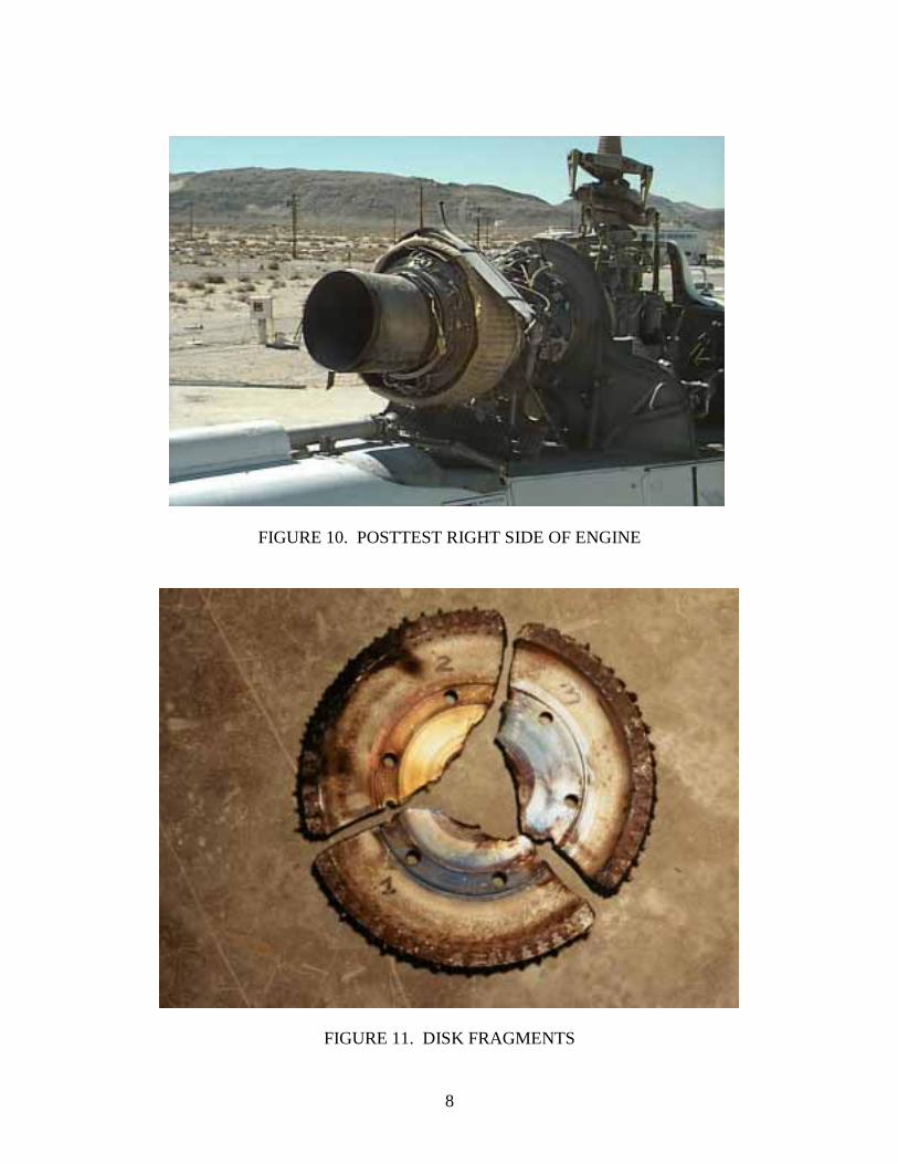
FIGURE 10. POSTTEST RIGHT SIDE OF ENGINE
FIGURE 11. DISK FRAGMENTS
8
CONCLUSIONS
The Pepin containment ring successfully contained the T53 second stage power turbine fragments. This fiber material, Kevlar 29 reinforced with titanium rods at 45° angles, is a good baseline ballistic fabric for containment structures. This is based on the specifi c containment fragment energy of the containment ring.
All three fragments penetrated through the combustor case and were embedded inside the containment ring. Minimum interactions between the immediate engine components and fragments were observed.
This test demonstrated the capability to contain a tri-hub burst on a medium sized turboshaft helicopter engine. Practical issues related to clearance for maintenance on a day to day basis as well as design for ring expansion during the failure are difficult challenges that must be considered for production of this type of a system.
9/10

Appendix – List of FAA Technical Reports Published in FY98
Report Number Title
R&D Highlights 1998 Highlights of the major accomplishments and applications.
DOT/FAA/AR-TN97/50 Comparison of Radial and Bias-Ply Tire Heating on a B-727 Aircraft
DOT/FAA/AR-97/99 Fire-Resistant Materials: Research Overview
DOT/FAA/AR-95/18 User’s Manual for the FAA Research and Development Electromagnetic Database (FRED)
DOT/FAA/AR-97/7 Advanced Pavement Design: Finite Element Modeling for Rigid Pavement Joints, Report II: Model Development
DOT/FAA/AR-97/26 Impact of New Large Aircraft on Airport Design
DOT/FAA/AR-97/64 Operational Evaluation of a Health and Usage Monitoring Systems (HUMS)
DOT/FAA/AR-TN98/15 Fire Testing of Ethanol-Based Hand Cleaner
DOT/FAA/AR-95/111 Stress-Intensity Factors for Elliptical Cracks Emanating from Countersunk Rivet Holes
DOT/FAA/AR-97/9 An Acoustic Emission Test for Aircraft Halon 1301 Fire Extinguisher Bottles
DOT/FAA/AR-97/37 Development of an Improved Magneto-Optic/Eddy-Current Imager
DOT/FAA/AR-97/69 Automated Inspection of Aircraft
DOT/FAA/AR-97/5 Marginal Aggregates in Flexible Pavements: Field Evaluation
DOT/FAA/AR-97/87 A Predictive Methodology for Delamination Growth in Laminated Composites, Part I: Theoretical Development and Preliminary Experimental Results
DOT/FAA/AR-TN97/103 Initial Development of an Exploding Aerosol Can Simulator
DOT/FAA/AR-97/56 Applications of Fracture Mechanics to the Durabilit y of Bonded Composite Joints
A-1
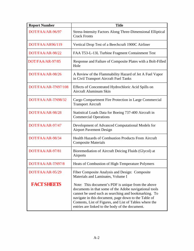
Report Number Title
DOT/FAA/AR-96/97 Stress-Intensity Factors Along Three-Dimensional Elliptical Crack Fronts
DOT/FAA/AR96/119 Vertical Drop Test of a Beechcraft 1900C Airliner
DOT/FAA/AR-98/22 FAA T53-L-13L Turbine Fragment Containment Test
DOT/FAA/AR-97/85 Response and Failure of Composite Plates with a Bolt-Filled Hole
DOT/FAA/AR-98/26 A Review of the Flammabilit y Hazard of Jet A Fuel Vapor in Civil Transport Aircraft Fuel Tanks
DOT/FAA/AR-TN97/108 Effects of Concentrated Hydrochloric Acid Spills on Aircraft Aluminum Skin
DOT/FAA/AR-TN98/32 Cargo Compartment Fire Protection in Large Commercial Transport Aircraft
DOT/FAA/AR-98/28 Statistical Loads Data for Boeing 737-400 Aircraft in Commercial Operations
DOT/FAA/AR-97/47 Development of Advanced Computational Models for Airport Pavement Design
DOT/FAA/AR-98/34 Health Hazards of Combustion Products From Aircraft Composite Materials
DOT/FAA/AR-97/81 Bioremediation of Aircraft Deicing Fluids (Glycol) at Airports
DOT/FAA/AR-TN97/8 Heats of Combustion of High-Temperature Polymers
DOT/FAA/AR-95/29
FACT SHEETS
Fiber Composite Analysis and Design: Composite Materials and Laminates, Volume I
Note: This document’s PDF is unique from the above documents in that some of the Adobe navigational tools cannot be used such as searching and bookmarking. To navigate in this document, page down to the Table of Contents, List of Figures, and List of Tables where the entries are linked to the body of the document.
A-2