DOT600 Roadbed Water Content Meter - Campbell Sci · field sites are compacted using a vertical...
28
DOT600 Roadbed Water Content Meter 1/10 Copyright © 2010 Campbell Scientific, Inc.
Transcript of DOT600 Roadbed Water Content Meter - Campbell Sci · field sites are compacted using a vertical...
DOT600 RoadbedWater Content Meter
1/10
C o p y r i g h t © 2 0 1 0C a m p b e l l S c i e n t i f i c , I n c .

Warranty and Assistance The DOT600 ROADBED WATER CONTENT METER is warranted by CAMPBELL SCIENTIFIC, INC. to be free from defects in materials and workmanship under normal use and service for twelve (12) months from date of shipment unless specified otherwise. Batteries have no warranty. CAMPBELL SCIENTIFIC, INC.'s obligation under this warranty is limited to repairing or replacing (at CAMPBELL SCIENTIFIC, INC.'s option) defective products. The customer shall assume all costs of removing, reinstalling, and shipping defective products to CAMPBELL SCIENTIFIC, INC. CAMPBELL SCIENTIFIC, INC. will return such products by surface carrier prepaid. This warranty shall not apply to any CAMPBELL SCIENTIFIC, INC. products which have been subjected to modification, misuse, neglect, accidents of nature, or shipping damage. This warranty is in lieu of all other warranties, expressed or implied, including warranties of merchantability or fitness for a particular purpose. CAMPBELL SCIENTIFIC, INC. is not liable for special, indirect, incidental, or consequential damages.
Products may not be returned without prior authorization. The following contact information is for US and International customers residing in countries served by Campbell Scientific, Inc. directly. Affiliate companies handle repairs for customers within their territories. Please visit www.campbellsci.com to determine which Campbell Scientific company serves your country.
To obtain a Returned Materials Authorization (RMA), contact CAMPBELL SCIENTIFIC, INC., phone (435) 753-2342. After an applications engineer determines the nature of the problem, an RMA number will be issued. Please write this number clearly on the outside of the shipping container. CAMPBELL SCIENTIFIC's shipping address is:
CAMPBELL SCIENTIFIC, INC. RMA#_____ 815 West 1800 North Logan, Utah 84321-1784
For all returns, the customer must fill out a “Declaration of Hazardous Material and Decontamination” form and comply with the requirements specified in it. The form is available from our website at www.campbellsci.com/repair. A completed form must be either emailed to [email protected] or faxed to 435-750-9579. Campbell Scientific will not process any returns until we receive this form. If the form is not received within three days of product receipt or is incomplete, the product will be returned to the customer at the customer’s expense. Campbell Scientific reserves the right to refuse service on products that were exposed to contaminants that may cause health or safety concerns for our employees.

DOT600 Table of Contents PDF viewers note: These page numbers refer to the printed version of this document. Use the Adobe Acrobat® bookmarks tab for links to specific sections.
1. General Description.....................................................1
2. What Parts Comprise the DOT600 .............................2
3. Specifications ..............................................................3
4. User Interface for Measurement and Control............4 4.1 The Keypad...............................................................................................4 4.2 Main Menu ...............................................................................................4
4.2.1 Project Information .........................................................................5 4.2.2 Test ID Data....................................................................................5 4.2.3 Make Measurements .......................................................................6 4.2.4 System Menu ..................................................................................6 4.2.5 Measurement Report .......................................................................6
5. Making Measurements with the DOT600 ...................7 5.1 Tare Scale .................................................................................................8 5.2 Fill Sample Chamber ................................................................................9
5.2.1 Weigh the Sample ...........................................................................9 5.3 Compress Sample and Measure Water Content......................................10
5.3.1 Write Measurement Data to Record..............................................13 5.3.2 Start New Test...............................................................................14
5.4 Removing Samples .................................................................................14
6. Detailed Description ..................................................15 6.1 Power System .........................................................................................15
6.1.1 Battery, Charger and Power Switch..............................................15 6.2 CR850 Datalogger ..................................................................................15 6.3 Water Content Measurement ..................................................................15
6.3.1 Electronics and Waveguide...........................................................15 6.3.2 Sample Chamber Volume and Compression Force ......................16 6.3.3 Water Content Calibration ............................................................16
7. Maintenance ...............................................................16
i

DOT600 Table of Contents
ii
Appendix
A. Design and Calibration ...........................................A-1 A.1 Description of Basic Technology........................................................ A-1 A.2 Description of the Modified Device.................................................... A-2 A.3 Detailed Description of any Field and Laboratory Work.................... A-2 A.4 Displacement Sensor Calibration ........................................................ A-3 A.5 Sensitivity of Weight Position on Scale Surface................................. A-4 A.6 Soil Water Content Calibration........................................................... A-4 A.7 Description of the Test Performed and Factors Which Could Have
Effect on Results of DOT600 Measurements.................................... A-5
Figures 1. Cross sectional drawing shows mounting of battery and charger/
regulator beneath panel ..................................................................... 15 A-1. Typical scale calibration. The standard error is 0.013 g .................... A-3 A-2. Typical calibration data for the displacement sensors ....................... A-4 A-3. Partial calibration set showing calibration data and equation.
The effect of clay content on sensor response is apparent .............. A-5
Tables 1. Common and Special Keypad Functions ................................................... 4 2. Information in the report ............................................................................ 6

DOT600 Roadbed Water Content Meter 1. General Description
The DOT600 is a portable device for measuring the water content of soils used in construction of roads, parking lots, foundations, etc. Samples collected from field sites are compacted using a vertical stress of (15-45 PSI), then the water content is measured using dielectric permittivity sensitive methods. A separate scale and magnetic linear sensors measure the sample volume and mass, which allows calculation of bulk density and conversion of the measured volumetric water content to gravimetric water content. Measurement results are written to a data table for permanent record. All measurements are controlled by a Campbell Scientific CR850 datalogger which includes an 8 line display and keypad for interface.
1

DOT600 Roadbed Water Content Meter
2. What Parts Comprise the DOT600 DOT600 components are housed in a rugged case. Contained in the case are:
1. Cable to charge DOT 600 from AC power source 2. Sample chamber base 3. Sample chamber cylinder 4. Ratcheting box-end wrench 5. Compression cap 6. Sieve, #4 mesh 7. DOT600 operating manual 8. RS-232 serial cable 9. PC200W software 10. External Keypad
2

DOT600 Roadbed Water Content Meter
3. Specifications Power Battery 2.9 Ahr rechargeable sealed lead-acid battery Operating temperature range: -20°C to 60°C Standby charge retention at 20°C for one year = 95% Lifetime approximately 500 cycles with discharge to 50% followed by recharge. See section Power System
Scale Capacity = 1000 g Accuracy = ±0.032% Repeatability = 0.02% FS The scale has overload protection in both the up and down directions during shipping. But it only has overload protection in the down direction during use.
Water Content Measurement Resolution = 1% volumetric water content Precision = 0.75% volumetric water content
Resolution is the minimum change in the measured parameter, water content, that the sensor can repeatedly detect.
Precision is the expected range for repeated measurements on the same sample.
Accuracy is defined by comparing DOT600 measured water contents to independently determined values. The independent method is water content by gravimetric method (weighing sample before and after oven drying).
The DOT600 water content measurement uses a calibration to convert sensor output period to volumetric water content. This calibration was derived at the factory for various soil types. The calibration coefficients used are determined by the material type selected by the user. Repeated measurements on the sandy loam soil over the water content range from air dry to about 70% saturation show deviations from independent measurements of less than ±1.5% volumetric water content.
Since the gravimetric water content measurement uses sample volume and weight to convert from measured volumetric water content, the accuracy of the gravimetric water content will be less than the volumetric value because of inherent errors of the volume and weight measurements.
Sample Volume and Applied Force Measurement Sample Volume ±1.5% for compressed sampled with thickness between .400 in to 1.000 in. Sensitive Volume The electromagnetic field penetrates the sample 0.39 in. Sensitive volume is about 3.5 in3. Applied vertical stress range and accuracy Applied vertical stress: 0 to 45 PSI. Applied vertical stress measurement accuracy: 1.7 PSI.
3

DOT600 Roadbed Water Content Meter
4. User Interface for Measurement and Control The Measurement and Control Datalogger has a built-in ruggedized membrane-switch keypad for control and a display with 8 lines and 21 characters per line. Measurement control uses a hierarchical structure of menus and submenus.
4.1 The Keypad The keypad keys that are commonly used or have special functions are listed in Table 1.
TABLE 1. Common and Special Keypad Functions
Key Usage
[2] and [8] Navigate up and down through the menu list one line at a time
[Enter] Selects the line or toggles the option of the line the cursor is on
[Esc] Backs up one level in the menu
[Home] Moves cursor to top of the list
[End] Moves cursor to bottom of the list
[BkSpc] Delete character to the left
[Shift] Change alpha character selected (shown at top right)
[Num Lock] Change to numeric entry
4.2 Main Menu The Main Menu is the starting point for each set of measurements and is discussed in this section.
4
DOT600 Roadbed Water Content Meter
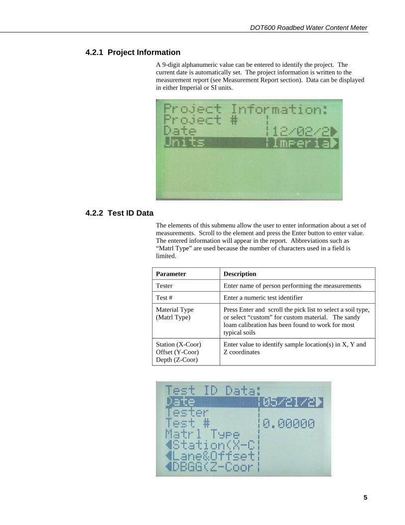
4.2.1 Project Information A 9-digit alphanumeric value can be entered to identify the project. The current date is automatically set. The project information is written to the measurement report (see Measurement Report section). Data can be displayed in either Imperial or SI units.
4.2.2 Test ID Data The elements of this submenu allow the user to enter information about a set of measurements. Scroll to the element and press the Enter button to enter value. The entered information will appear in the report. Abbreviations such as “Matrl Type” are used because the number of characters used in a field is limited.
Parameter Description
Tester Enter name of person performing the measurements
Test # Enter a numeric test identifier
Material Type (Matrl Type)
Press Enter and scroll the pick list to select a soil type, or select “custom” for custom material. The sandy loam calibration has been found to work for most typical soils
Station (X-Coor) Offset (Y-Coor) Depth (Z-Coor)
Enter value to identify sample location(s) in X, Y and Z coordinates
5

DOT600 Roadbed Water Content Meter
4.2.3 Make Measurements Scrolling to and selecting Make Measurements allows selection of measurement steps and displays the results as measurements are made. See Measurement section for detailed description.
4.2.4 System Menu The System Menu allows user access to numerous settings and data. For operation of the DOT600, the only control of interest is System Menu/Configure, Settings/Display. From this menu the user can control the display back lighting, contrast and display timeout to save power. The calibration file can also be edited through this menu, and a list of files stored on the datalogger CPU can be accessed.
4.2.5 Measurement Report A command in the measurement sequence writes measurement data to a file. The information in the file is similar to information recorded on data sheets commonly used by Departments of Transportation. Table 2 describes the report information. Units are SI or Imperial, as selected by user.
TABLE 2. Information in the report.
Variable Description
TIMESTAMP Date and time when measurements are written to data file
RECORD Record number
Project# Value entered by user to identify project
DMY Day, month and year
Tester Value entered by user to identify person making measurements
TestNum Incremental record number. Automatically increments after each data write to output table
XCoordinate, YCoordinate, ZCoordinate
Values entered by user to identify sample location
Per Output period of measurement circuit
Freq Output frequency of measurement circuit
Gwc Gravimetric water content
Vwc Volumetric water content
Material Type Soil texture
Dry Bulk Density Sample dry bulk density
Sample Weight Sample net weight
SampleVolume Sample volume
SampleDepth Depth or thickness of sample at time of measurement
6

DOT600 Roadbed Water Content Meter
Sample Vertical Stress Vertical stress applied to compress the sample
CompressionForce Force applied to compress the sample
batt_volt_Min Minimum system battery voltage during measurement period
5. Making Measurements with the DOT600 Level the DOT600 case using the built-in bubble.
Turn DOT600 on and wait for program to compile and Main Menu to appear. After entering Project Information and Test ID Data values as desired, select Make Measurements in the Main Menu.
The Measurement selection allows the user to select the various measurement functions. The Process Step shows the status of the measurement. Beginning at Test #, the user can scroll down to view measurement values. Or the user may change the Test # at this location.
7

DOT600 Roadbed Water Content Meter
5.1 Tare Scale Place the empty sample chamber base and cylinder on the scale.
The scale is very sensitive. Do not pull up on scale during use. Doing so could permanently damage the scale.
CAUTION
In the top level menu select Make Measurements, select Measurement, and then select Tare Scale. The display will then shift back to the Make Measurement menu. When the Measurement value is 0 the measurement is complete.
Weighing measurements take about 3 seconds. When the tare measurement is complete the weight of the item on the scale is displayed next to Tare (g) (found at the bottom of the list. Use arrow keys to scroll down list). If an accurate measurement is not made within 9 seconds, a “wind error” message will appear on the screen and the tare process will need to be started again.
8

DOT600 Roadbed Water Content Meter
5.2 Fill Sample Chamber On a flat surface away from the case, place the sieve on the sample chamber and fill the sieve with material. Push the material through the sieve using fingers or tool. Do not pack the material into the sample chamber, only fill it.
Sample depth measurement range is 0.4” (~1cm) to 1.0” (2.5cm). NOTE
Once the material is pushed through the sieve, tap the sample chamber/sieve on a hard surface and remove the sieve. Brush away any material on the side or bottom of the sample chamber. Take care to not let the base detach from the sample chamber cylinder while moving the filled sample chamber. It is advisable to hold the sample chamber at the base when moving the chamber to the scale or placing on contact pins.
5.2.1 Weigh the Sample Place the filled sample chamber on the scale.
9

DOT600 Roadbed Water Content Meter
Select Measurement, select Weigh Sample. The display will shift to the Make Measurement menu.
When the weighing process is complete the net sample weight is displayed next to Weight (g), and the process step will read “weigh”. If an accurate weight measurement is not made within 9 seconds, a “wind error” message will appear on the screen and the weighing process will need to be started again.
5.3 Compress Sample and Measure Water Content Place the filled and weighed sample chamber base over the pins with the indices aligned. The base should rest flat against the surface. Make sure there is no soil under sample chamber, which could affect volume accuracy.
10

DOT600 Roadbed Water Content Meter
Place the compression cap on the sample chamber by aligning the pins in slots and twist to lock.
Turn the compression nut clockwise by hand or with a wrench until you can feel the sample being compressed.
11
DOT600 Roadbed Water Content Meter
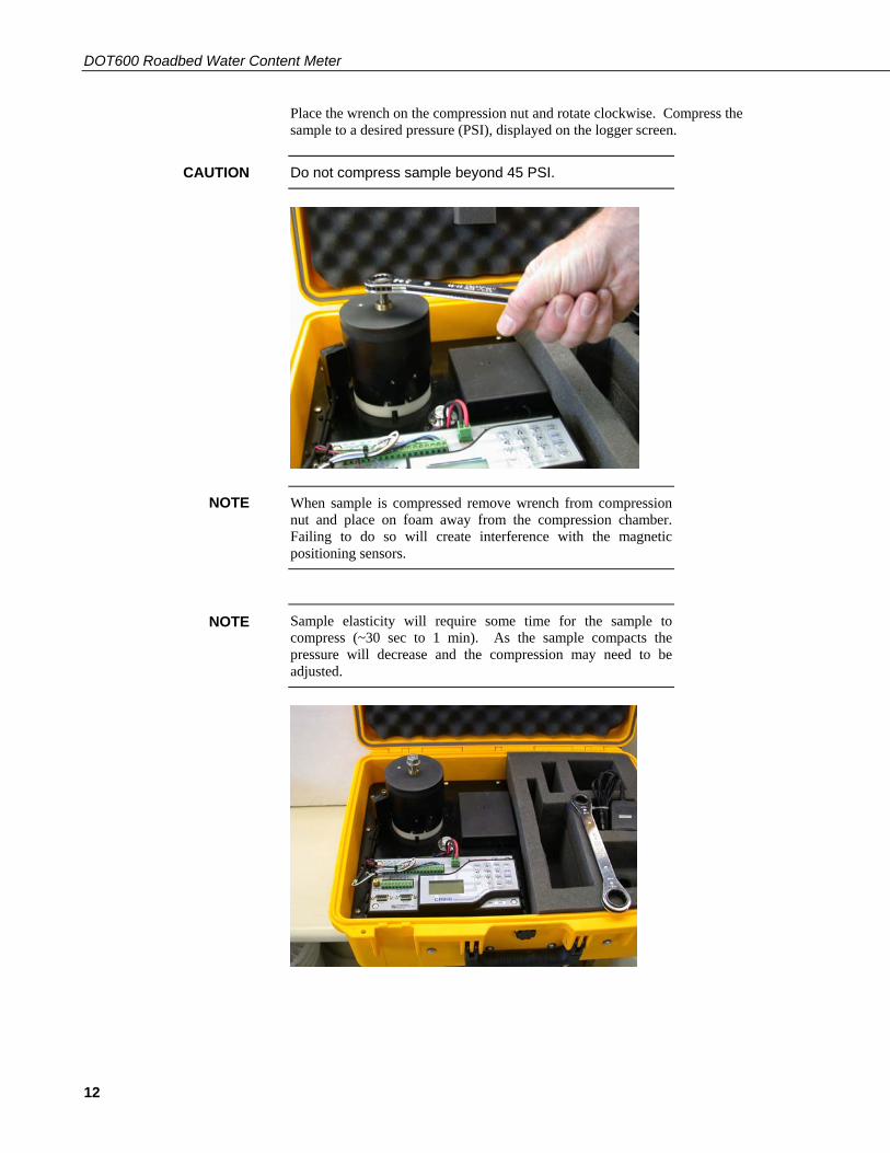
Place the wrench on the compression nut and rotate clockwise. Compress the sample to a desired pressure (PSI), displayed on the logger screen.
Do not compress sample beyond 45 PSI. CAUTION
When sample is compressed remove wrench from compression nut and place on foam away from the compression chamber. Failing to do so will create interference with the magnetic positioning sensors.
NOTE
Sample elasticity will require some time for the sample to compress (~30 sec to 1 min). As the sample compacts the pressure will decrease and the compression may need to be adjusted.
NOTE
12

DOT600 Roadbed Water Content Meter
When the target pressure is reached select Measurement, select Sample VWC.
Press Enter to
1. measure volumetric water content, VWC 2. record applied pressure 3. measure sample volume 4. calculate sample dry bulk density 5. calculate gravimetric water content, GWC
The values are displayed on the logger screen. Additional values can be seen by scrolling down with the arrow key (8 key).
5.3.1 Write Measurement Data to Record Any operation from Tare_Scale to Sample_VWC may be repeated at this time and values updated accordingly.
Once the measurement is finished, data may be recorded by selecting Measurement, and Rec Sample Data to write the sample data to datalogger storage. Once data is recorded it is stored in a data table named SampleData. The Sample Data file can be collected from the Datalogger using a PC and PC200 software (supplied).
13

DOT600 Roadbed Water Content Meter
5.3.2 Start New Test Select Measurement, select New Sample.
Press Enter to:
1. zero all temporary values 2. increment test #
5.4 Removing Samples Remove the sample chamber completely from the enclosure. Loosen the compression nut by turning the ratchet in a counter clockwise direction. Remove the compression cap. Remove the sample chamber ring from the sample chamber base. The sample can then be removed from the sample ring.
14

DOT600 Roadbed Water Content Meter
6. Detailed Description 6.1 Power System 6.1.1 Battery, Charger and Power Switch
A 2.9 Ahr battery and a CH100 charger/regulator (manufactured by Campbell Scientific) are mounted beneath the panel as shown in Figure 1.
A wiring harness distributes power and connects the charger to a jack located on the panel in the upper-left corner near the power switch. This jack mates with the wires from a wall transformer and allows charging the battery. The 2.9 Ahr battery will provide 24 hours of continuous operation. The battery will not operate properly under 11.5V.
FIGURE 1. Cross sectional drawing shows mounting of battery and charger/regulator beneath panel.
6.2 CR850 Datalogger The CR850 Measurement and Control Datalogger monitors all measurement sensors, executes measurement program and stores the measurement results as a time-stamped record. These operations are controlled by a custom datalogger program designed by Campbell Scientific.
6.3 Water Content Measurement 6.3.1 Electronics and Waveguide
The water content measurement uses a method that is sensitive to dielectric permittivity. The permittivity of water is at least an order of magnitude greater than other soil constituents. Other than air, which has permittivity of one, water is the only soil constituent that changes with time.
This method is sensitive to volumetric water content which is reported directly by the datalogger. Conversion to gravimetric water content is calculated from the wet weight, volume and volumetric water content.
15

DOT600 Roadbed Water Content Meter
16
A circuit board containing water content measurement electronics is mounted below the sample chamber and is electrically connected to a waveguide mounted in the bottom of the chamber. As water content of the sample increases, the oscillation frequency of the circuit decreases, and this frequency is related to water content through empirical calibration.
6.3.2 Sample Chamber Volume and Compression Force The sample volume is calculated from known diameter of the sample chamber and the distance between the bottom of the chamber and the compression piston. The distance is measured with a magnetic displacement sensor. The compression force is calculated by knowing the distance between the compression piston and the spring compression plate. This distance will determine how far the springs between these two plates have compressed. This is determined by comparing two different magnetic displacement sensors. Knowing the distance the springs have compressed and the spring rate we can then calculate the compression force.
6.3.3 Water Content Calibration The water content measurement uses a calibration derived by the DOT600 manufacturer using soils with a range of textures. The calibration coefficients are selected using material type. The DOT600 response can be affected by soil salinity in addition to clay content. Soils high in clay and electrical conductivity (greater than about 1.5 deciSiemens/meter) may require a soil specific calibration. The water content response is linear so a one-point calibration will work.
7. Maintenance Sample Chamber and Compression Cap
The sample chamber and compression cap should be cleaned after use. Failure to do so could affect future water content measurements.
The lead screw should be lubricated as needed with a liquid graphite lubricant.
Enclosure
Before placing the sample chamber in the location for measurement, the surface should be clear of any dust or soil.
Calibration
The unit should be recalibrated at least once for each two-year period.
Appendix A. Design and Calibration A.1 Description of Basic Technology
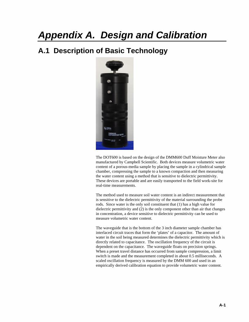
The DOT600 is based on the design of the DMM600 Duff Moisture Meter also manufactured by Campbell Scientific. Both devices measure volumetric water content of a porous-media sample by placing the sample in a cylindrical sample chamber, compressing the sample to a known compaction and then measuring the water content using a method that is sensitive to dielectric permittivity. These devices are portable and are easily transported to the field work-site for real-time measurements.
The method used to measure soil water content is an indirect measurement that is sensitive to the dielectric permittivity of the material surrounding the probe rods. Since water is the only soil constituent that (1) has a high value for dielectric permittivity and (2) is the only component other than air that changes in concentration, a device sensitive to dielectric permittivity can be used to measure volumetric water content.
The waveguide that is the bottom of the 3 inch diameter sample chamber has interlaced circuit traces that form the ‘plates’ of a capacitor. The amount of water in the soil being measured determines the dielectric permittivity which is directly related to capacitance. The oscillation frequency of the circuit is dependent on the capacitance. The waveguide floats on precision springs. When a preset travel distance has occurred from sample compression, a limit switch is made and the measurement completed in about 0.5 milliseconds. A scaled oscillation frequency is measured by the DMM 600 and used in an empirically derived calibration equation to provide volumetric water content.
A-1
Appendix A. Design and Calibration
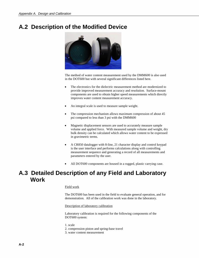
A.2 Description of the Modified Device
The method of water content measurement used by the DMM600 is also used in the DOT600 but with several significant differences listed here.
• The electronics for the dielectric measurement method are modernized to provide improved measurement accuracy and resolution. Surface-mount components are used to obtain higher speed measurements which directly improves water content measurement accuracy.
• An integral scale is used to measure sample weight.
• The compression mechanism allows maximum compression of about 45 psi compared to less than 3 psi with the DMM600
• Magnetic displacement sensors are used to accurately measure sample volume and applied force. With measured sample volume and weight, dry bulk density can be calculated which allows water content to be expressed in gravimetric terms.
• A CR850 datalogger with 8-line, 21 character display and control keypad is the user interface and performs calculations along with controlling measurement sequence and generating a record of all measurements and parameters entered by the user.
• All DOT600 components are housed in a rugged, plastic carrying case.
A.3 Detailed Description of any Field and Laboratory Work
Field work
The DOT600 has been used in the field to evaluate general operation, and for demonstration. All of the calibration work was done in the laboratory.
Description of laboratory calibration
Laboratory calibration is required for the following components of the DOT600 system:
1. scale 2. compression piston and spring-base travel 3. water content measurement
A-2

Appendix A. Design and Calibration
Calibrating the DOT600 scale is a simple matter of placing objects of known weight on the scale and recording the output voltage. Precision calibration weights manufactured by Ohaus and checked on an independent scale were used. Figure 1 show the linear relationship
Weighing scale calibration
y = 1065x - 80.773R2 = 1
-100
0
100
200
300
400
500
600
700
0.000 0.100 0.200 0.300 0.400 0.500 0.600 0.700
voltage output (V)
wei
ght (
g)
FIGURE A-1. Typical scale calibration. The standard error is 0.013 g.
A.4 Displacement Sensor Calibration Magnetic displacement sensors provide position of both the compression piston and the plate above the compression springs. With the information both sample chamber volume and compression force can be derived. Calibration of the displacement sensors was performed by placing spacers of known length in the sample chamber and calibrating to measurement output voltage. The spacers were custom made with tolerance +/- 0.0005 inch. The error from the calibration and other error sources is considered in the performance specifications. Figure 2 show a typical displacement sensor calibration. Polynomial equations were used to define the calibration equations for all sensors.
A-3

Appendix A. Design and Calibration
Typical displacement sensor calibration
0.00
0.20
0.40
0.60
0.80
1.00
-40.000 -20.000 0.000 20.000 40.000 60.000 80.000
Displacement sensor output (millivolts)
Disp
lace
men
t (in
ches
)
FIGURE A-2. Typical calibration data for the displacement sensors.
A.5 Sensitivity of Weight Position on Scale Surface Small weights (diameter = 3 cm, weight = 200 g) were placed at various locations of a symmetrically defined grid superimposed on the scale surface. There were no significant differences among any of the positions. It is concluded that placing the sample chamber anywhere on the scale surface such that it is not extending over any edge of the scale will result in no error contribution to the measurement.
A.6 Soil Water Content Calibration Multiple soil water content calibrations are derived to cover a range of soil textures. Water content measurement methods that are sensitive to dielectric permittivity are inherently sensitive to soil texture and specifically clay content.
The calibrations were obtained by independently measuring sample volumetric water content. Soils mixed to a range of water contents were measured in the DOT600 in normal fashion. The cylindrically-shaped sample was removed from the sample chamber intact. This allows accurate measurement of the sample volume. Oven drying at 105C for 24 hours was used to determine sample gravimetric water content which is converted to volumetric water content by multiplying by the sample dry bulk density. Three repetitions were used for each soil at each water content.
A-4

Appendix A. Design and Calibration
0
0.05
0.1
0.15
0.2
0.25
0.3
0.35
0.4
0.45
15 20 25 30 35 40
Water content sensor output (microseconds)
volu
met
ric w
ater
con
tent
(m^3
m^-
3)
clay calibsand calibloam calibsilt calib
FIGURE A-3. Partial calibration set showing calibration data and equation. The effect of clay content on sensor response is apparent.
A.7 Description of the Test Performed and Factors Which Could Have Effect on Results of DOT600 Measurements
The scale/load cell
Weights from 100 grams to 1000 grams were placed at various locations of a symmetrically defined grid superimposed on the scale surface. The CR850 measures an average weight over 2.5 seconds. There were no significant differences in error among any of the positions. The total specified error of the load cell is ± 0.32g. From our testing the maximum error of the load cell was ± 0.22g, giving us a maximum error of .22% for a typical 100g soil sample. The load cells also appear to not have an error bias. It is concluded that placing the sample chamber anywhere on the scale surface such that it is not extending over any edge of the scale will result in no significant error contribution to the measurement.
Also during field testing of the scale we found wind to have an effect on scale accuracy. To remove the error caused by wind we added programming to determine if there was a rate of change due to wind. This code will prevent any spikes in weight, but if the scale is tared in a wind of 5mph and the sample is
A-5

Appendix A. Design and Calibration
A-6
weighted in a 10 mph wind there will be some error, so taring the scale and weighting the sample should be performed in the same environment.
The enclosure should also be leveled, using the bubble level next to the scale, to have accurate weight measurements.
Displacement Sensors/Sample Thickness/Compression Pressure
Magnetic displacement sensors provide position of both the compression piston and the plate above the compression springs. With the information both sample chamber volume and compression force can be derived.
Testing of the displacement sensor, used for measuring sample thickness, was performed by placing spacers of known length in the sample chamber and measurements were taken. The spacers were custom made with tolerance ± 0.0005 inches. The typical error from .400 inches to 1.00 inch was found to be ± .005 inches, with a maximum of ± .009 inches. Testing showed a positive error bias for thicknesses of .400 inches to .600 inches and a negative error bias for thicknesses of .600 inches to 1.00 inch. The error for sample thicknesses between .600 inches to 1.00 inch also tends to be minimized.
Testing of the displacement sensor, used for measuring spring compression, was done by using a load cell to determine compression pressure. Repeated measurements showed an error of ± 1.7 PSI with no bias.
Soil water content
Soil water content tests were conducted on multiple soil textures. This was done by measuring sample gravimetric water content using the DOT600. The cylindrically-shaped sample was removed from the sample chamber intact. It was then oven dried at 105C for 24 hours to determine sample dry weight, bulk density, gravimetric water content. Three repetitions were used for each soil and water mixture. Testing showed accuracy of ± 1.5% gravimetric water content. For example, a measured gravimetric water content of 10% has an actual value in the range of 8.5% to 11.5% gravimetric water content. Test bias for gravimetric water content was positive.

Campbell Scientific Companies
Campbell Scientific, Inc. (CSI) 815 West 1800 North Logan, Utah 84321 UNITED STATES
www.campbellsci.com • [email protected]
Campbell Scientific Africa Pty. Ltd. (CSAf) PO Box 2450
Somerset West 7129 SOUTH AFRICA
www.csafrica.co.za • [email protected]
Campbell Scientific Australia Pty. Ltd. (CSA) PO Box 444
Thuringowa Central QLD 4812 AUSTRALIA
www.campbellsci.com.au • [email protected]
Campbell Scientific do Brazil Ltda. (CSB) Rua Luisa Crapsi Orsi, 15 Butantã
CEP: 005543-000 São Paulo SP BRAZIL www.campbellsci.com.br • [email protected]
Campbell Scientific Canada Corp. (CSC)
11564 - 149th Street NW Edmonton, Alberta T5M 1W7
CANADA www.campbellsci.ca • [email protected]
Campbell Scientific Centro Caribe S.A. (CSCC)
300 N Cementerio, Edificio Breller Santo Domingo, Heredia 40305
COSTA RICA www.campbellsci.cc • [email protected]
Campbell Scientific Ltd. (CSL)
Campbell Park 80 Hathern Road
Shepshed, Loughborough LE12 9GX UNITED KINGDOM
www.campbellsci.co.uk • [email protected]
Campbell Scientific Ltd. (France) Miniparc du Verger - Bat. H
1, rue de Terre Neuve - Les Ulis 91967 COURTABOEUF CEDEX
FRANCE www.campbellsci.fr • [email protected]
Campbell Scientific Spain, S. L.
Psg. Font 14, local 8 08013 Barcelona
SPAIN www.campbellsci.es • [email protected]
Please visit www.campbellsci.com to obtain contact information for your local US or International representative.