Doppler CW Radar System, FM-CW Radar System, Moving Target Indication Radar System...
52
1 Lecture Topics Doppler CW Radar System, FM-CW Radar System, Moving Target Indication Radar System, and Pulsed Doppler Radar System
Transcript of Doppler CW Radar System, FM-CW Radar System, Moving Target Indication Radar System...
1
Lecture TopicsDoppler CW Radar System,
FM-CW Radar System,
Moving Target Indication Radar System, and
Pulsed Doppler Radar System
2
Remember that:
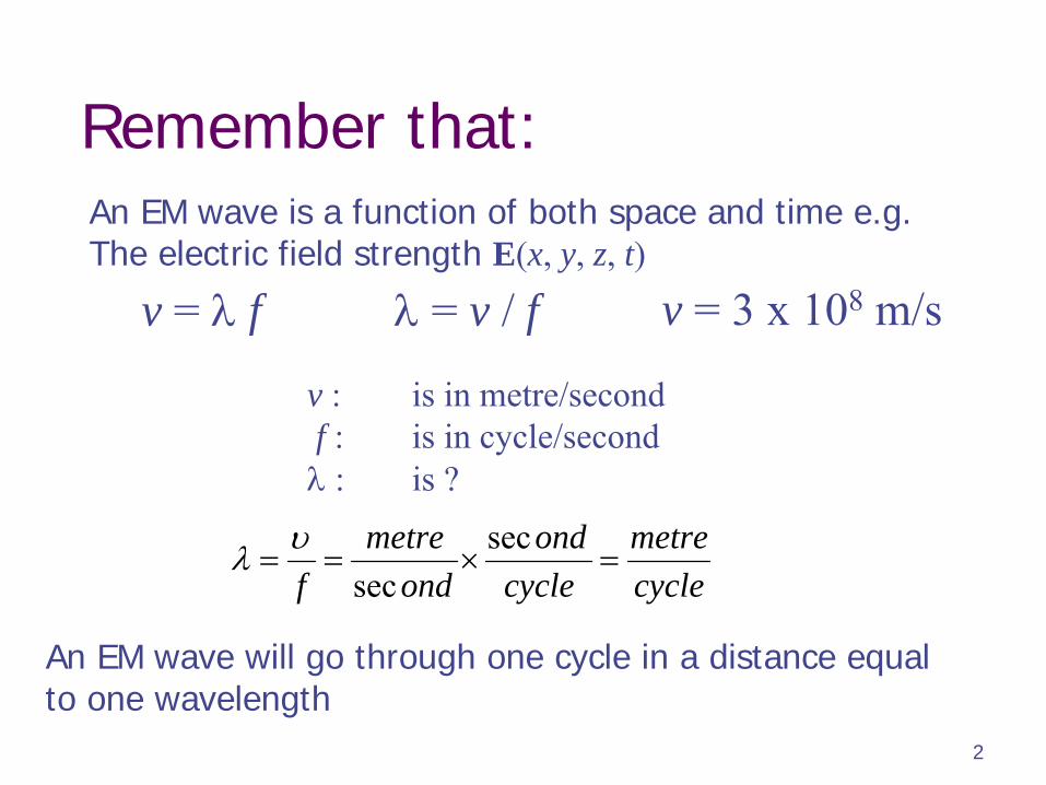
v =
f
= v / f v = 3 x 10⁸
m/s
v :
is in metre/secondf :
is in cycle/second
: is ?
An EM wave will go through one cycle in a distance equal to one wavelength
An EM wave is a function of both space and time e.g.The electric field strength E(x, y, z, t)
cyclemetre
cycleond
ondmetre
f
secsec
3
Interpretation
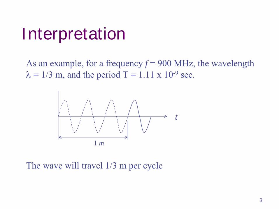
As an example, for a frequency f = 900 MHz, the wavelength
= 1/3 m, and the period T = 1.11 x 10⁻⁹
sec.
The wave will travel 1/3 m per cycle
t
1 m
4
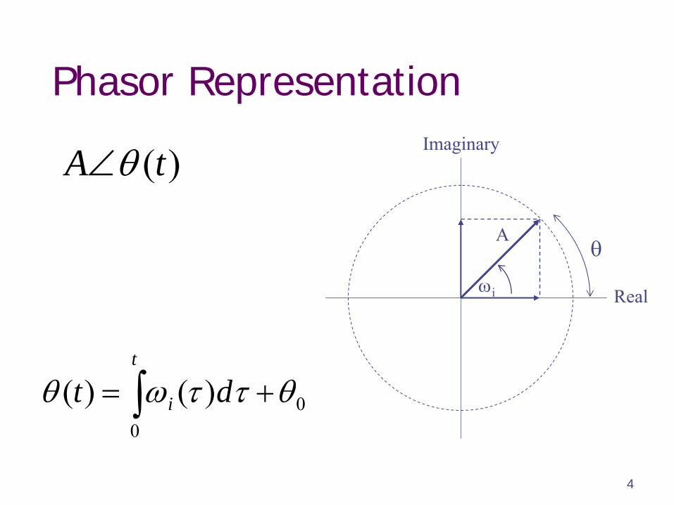
Phasor Representation
A
i
)(tA
t
i dt0
0)()(
Real
Imaginary
5
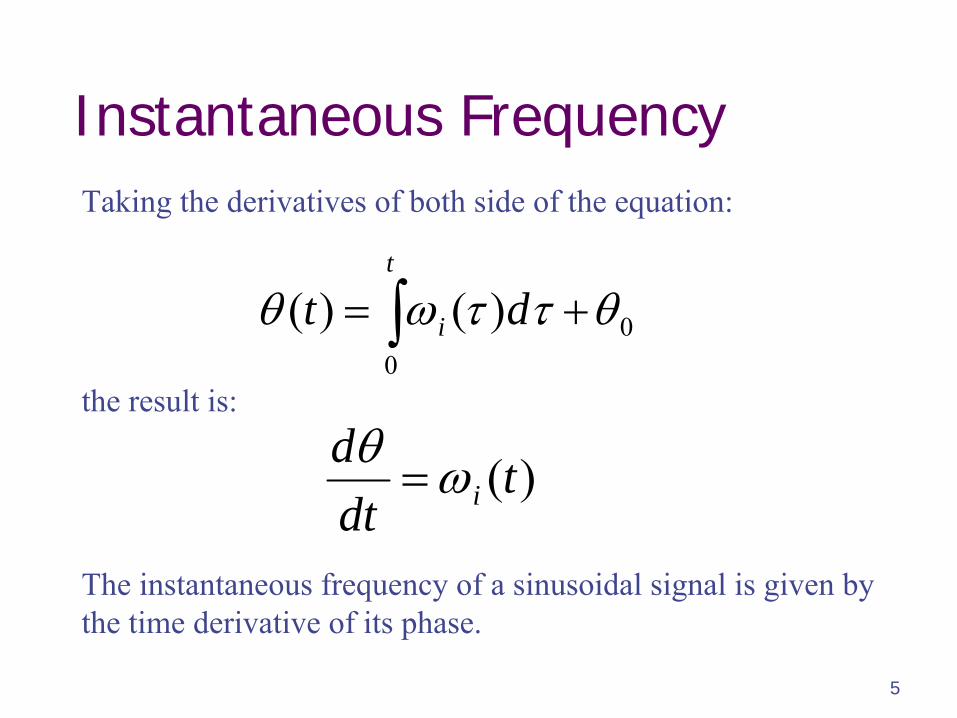
Instantaneous Frequency
)(tdtd
i
Taking the derivatives of both side of the equation:
t
i dt0
0)()(
the result is:
The instantaneous frequency of a sinusoidal signal is given by the time derivative of its phase.
6
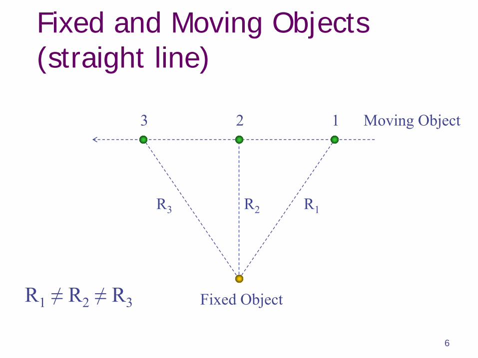
Fixed and Moving Objects (straight line)
123
Fixed Object
Moving Object
R1R3 R2
R1
≠
R2
≠
R3
7
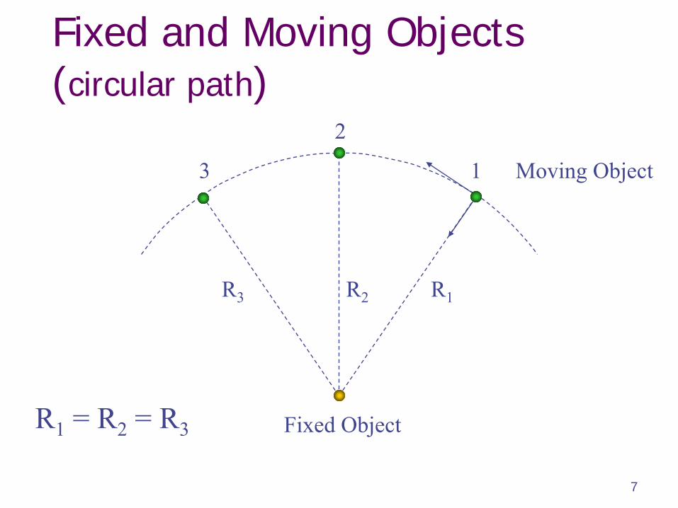
Fixed and Moving Objects (circular path)
1
2
3
Fixed Object
Moving Object
R1R3 R2
R1
= R2
= R3
8
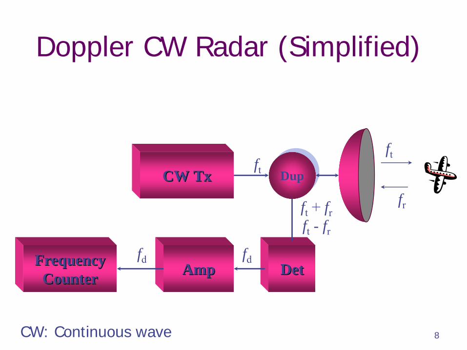
Doppler CW Radar (Simplified)
CW TxCW Tx
DetDetAmpAmp
DupDup
Frequency Frequency CounterCounter
ft
ft
+ frft
-
fr
fdfd
ft
fr
CW: Continuous wave
9
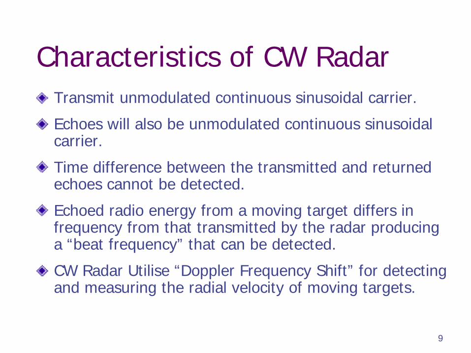
Characteristics of CW RadarTransmit unmodulated continuous sinusoidal carrier.
Echoes will also be unmodulated continuous sinusoidal carrier.
Time difference between the transmitted and returned echoes cannot be detected.
Echoed radio energy from a moving target differs in frequency from that transmitted by the radar producing a “beat frequency” that can be detected.
CW Radar Utilise “Doppler Frequency Shift” for detecting and measuring the radial velocity of moving targets.
10
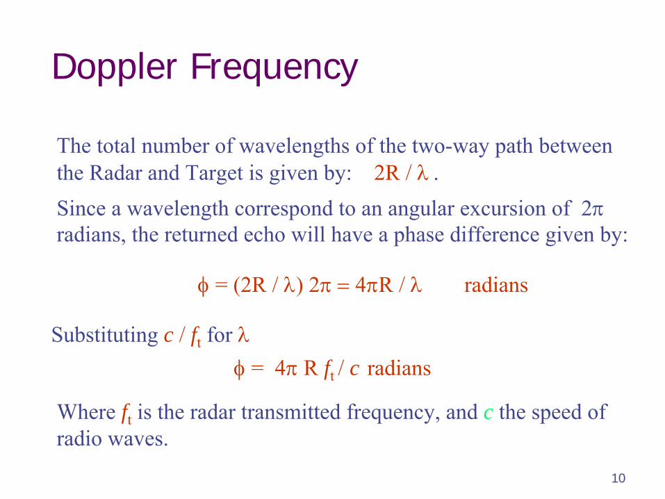
Doppler Frequency
The total number of wavelengths of the two-way path between the Radar and Target is given by: 2R /
Since a wavelength correspond to an angular excursion of 2 radians, the returned echo will have a phase difference given by:
= (2R / ) 24R /
radians
Substituting c /
ft
for
= 4R ft / c radians
Where
ft
is the radar transmitted frequency, and c the speed of radio waves.
11
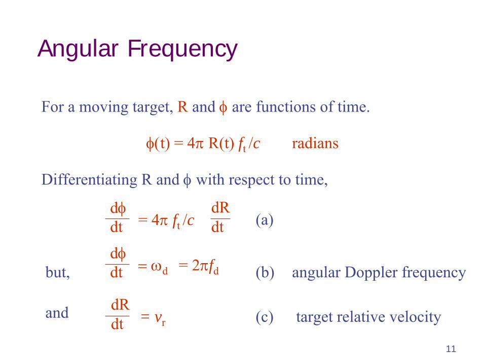
Angular Frequency
Differentiating R and
with respect to time,
t
= 4R(t) ft /c radians
For a moving target, R
and
are functions of time.
ddt = 4
ft /c
dRdt
ddt d = 2fd angular Doppler frequency
dRdt = vr target relative velocity
(a)
but,
and
(b)
(c)
12
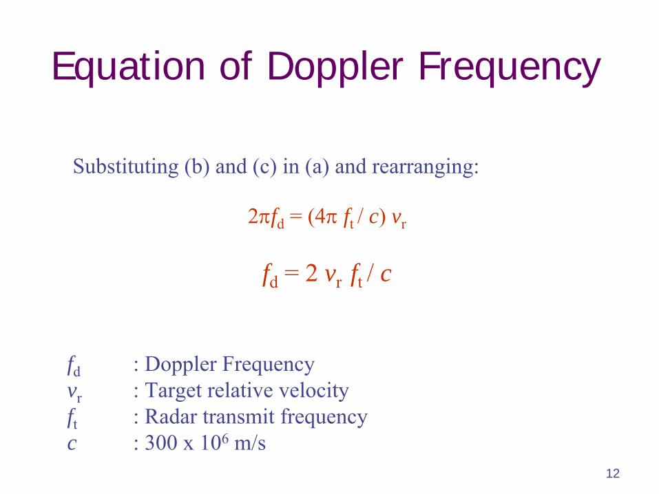
Equation of Doppler Frequency
2fd
= (4
ft / c) vr
fd
= 2 vr ft / c
Substituting (b) and (c) in (a) and rearranging:
fd
: Doppler Frequencyvr
: Target relative velocityft
: Radar transmit frequencyc : 300 x 106
m/s
13
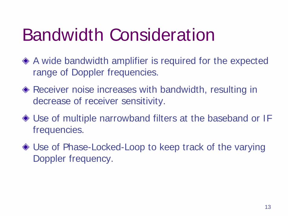
Bandwidth ConsiderationA wide bandwidth amplifier is required for the expected range of Doppler frequencies.
Receiver noise increases with bandwidth, resulting in decrease of receiver sensitivity.
Use of multiple narrowband filters at the baseband or IF frequencies.
Use of Phase-Locked-Loop to keep track of the varying Doppler frequency.
14
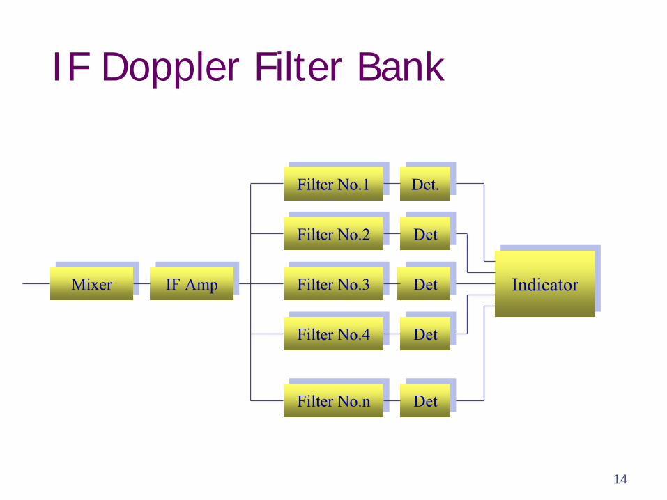
IF Doppler Filter Bank
Filter No.nFilter No.n
Filter No.4Filter No.4
Filter No.3Filter No.3
Filter No.2Filter No.2
Filter No.1Filter No.1
IndicatorIndicator
DetDet
DetDet
DetDet
DetDet
Det.Det.
IF AmpIF AmpMixerMixer
15
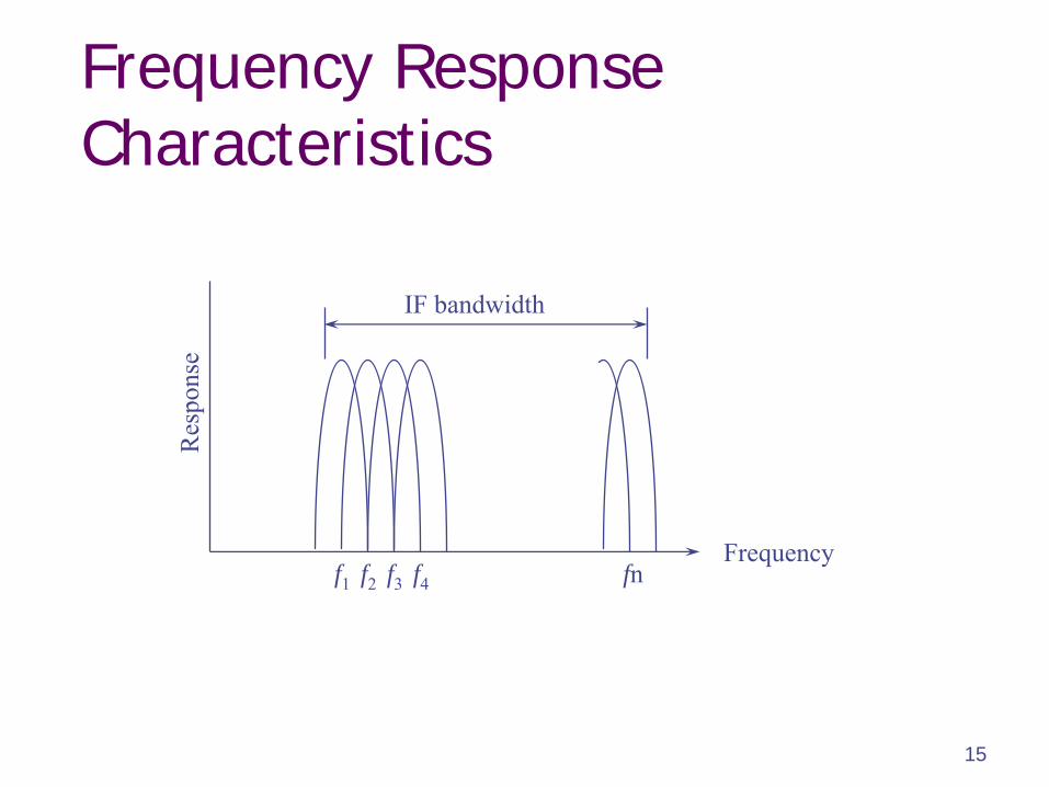
Frequency Response Characteristics
Frequency
Res
pons
e
f1 f2 f3 f4 fn
IF bandwidth
16
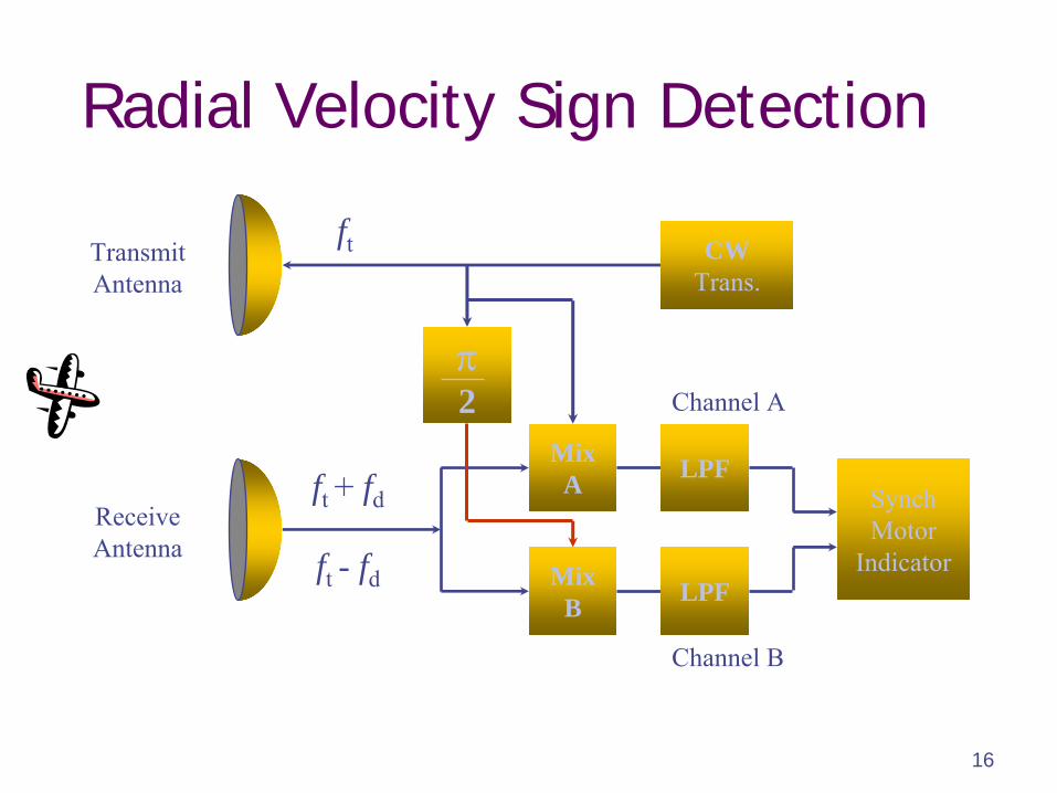
Radial Velocity Sign Detection
CWTrans.
MixA
MixB
2
SynchMotor
Indicator
Channel A
Channel B
TransmitAntenna
ReceiveAntenna
ft
ft +
fd
ft -
fd
LPF
LPF
17
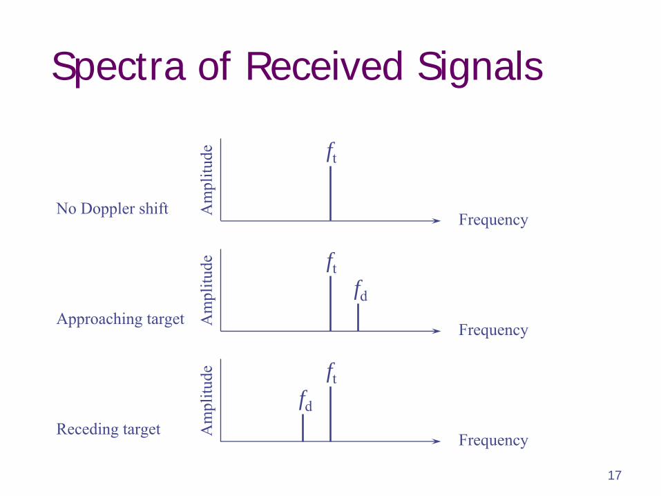
Spectra of Received Signals
Frequency
Frequency
Frequency
Am
plitu
deA
mpl
itude
Am
plitu
de
ft
ft
ft
fd
fd
No Doppler shift
Approaching target
Receding target
18
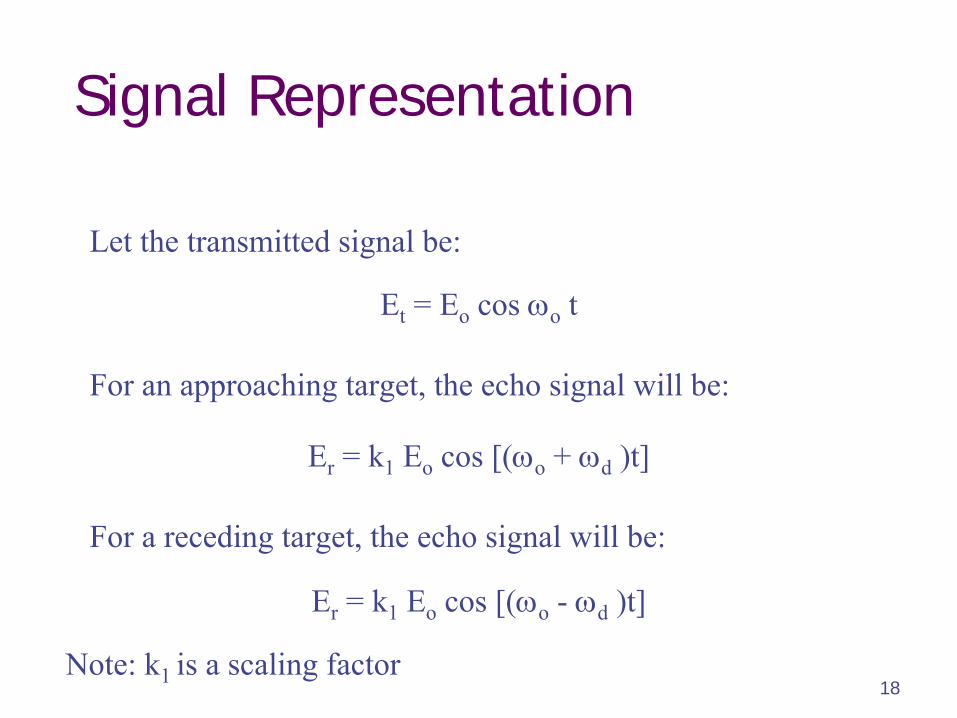
Signal Representation
Let the transmitted signal be:
Et
= Eo
cos o
t
Er
= k1
Eo
cos [(o
+ d
)t]
Er
= k1
Eo
cos [(o
-
d
)t]
For an approaching target, the echo signal will be:
For a receding target, the echo signal will be:
Note: k1 is a scaling factor
19
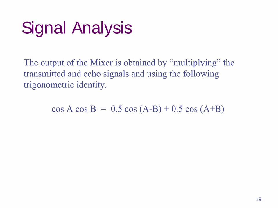
Signal Analysis
cos A cos B = 0.5 cos (A-B) + 0.5 cos (A+B)
The output of the Mixer is obtained by “multiplying”
the transmitted and echo signals and using the following trigonometric identity.
20
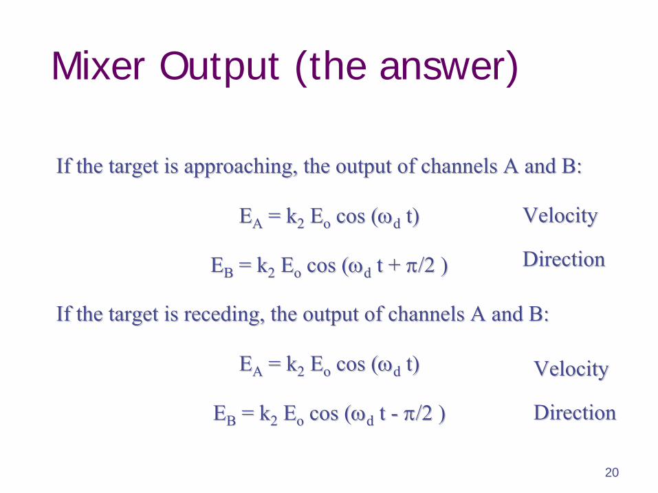
Mixer Output (the answer)
If the target is approaching, the output of channels A and B:If the target is approaching, the output of channels A and B:
EEAA
= k= k22
EEoo
cos (cos (dd
t)t)
EEBB
= k= k22
EEoo
cos (cos (dd
t + t + /2 )/2 )
EEAA
= k= k22
EEoo
cos (cos (dd
t)t)
EEBB
= k= k22
EEoo
cos (cos (dd
t t --
/2 )/2 )
If the target is receding, the output of channels A and B:If the target is receding, the output of channels A and B:
VelocityVelocity
DirectionDirection
VelocityVelocity
DirectionDirection
21
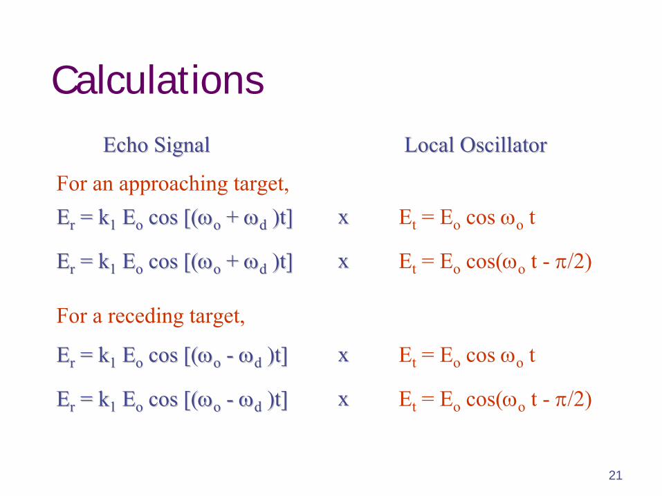
Calculations
Et
= Eo
cos o
tEErr
= k= k11
EEoo
cos [(cos [(oo
+ + dd
)t])t]
EErr
= k= k11
EEoo
cos [(cos [(oo
--
dd
)t])t]
Et
= Eo
cos(o
t -
/2)
Et
= Eo
cos o
t
Et
= Eo
cos(o
t -
/2)
xx
xx
xx
xx
EErr
= k= k11
EEoo
cos [(cos [(oo
+ + dd
)t])t]
EErr
= k= k11
EEoo
cos [(cos [(oo
--
dd
)t])t]
Echo SignalEcho Signal Local OscillatorLocal Oscillator
For an approaching target,
For a receding target,
22
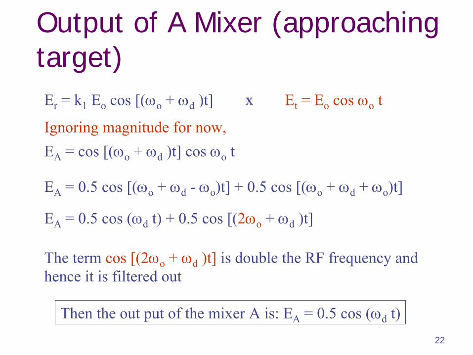
EA
= cos [(o
+ d
)t] cos o
t
EA
= 0.5 cos [(o
+ d
-
o
)t] + 0.5 cos [(o
+ d
+ o
)t]
EA
= 0.5 cos (d
t) + 0.5 cos [(2o
+ d
)t]
Ignoring magnitude for now,
Output of A Mixer (approaching target)
The term cos [(2o
+ d
)t]
is double the RF frequency and hence it is filtered out
Then the out put of the mixer A is: EA
= 0.5 cos (d
t)
Et
= Eo
cos o
tEr
= k1
Eo
cos [(o
+ d
)t] xx
23
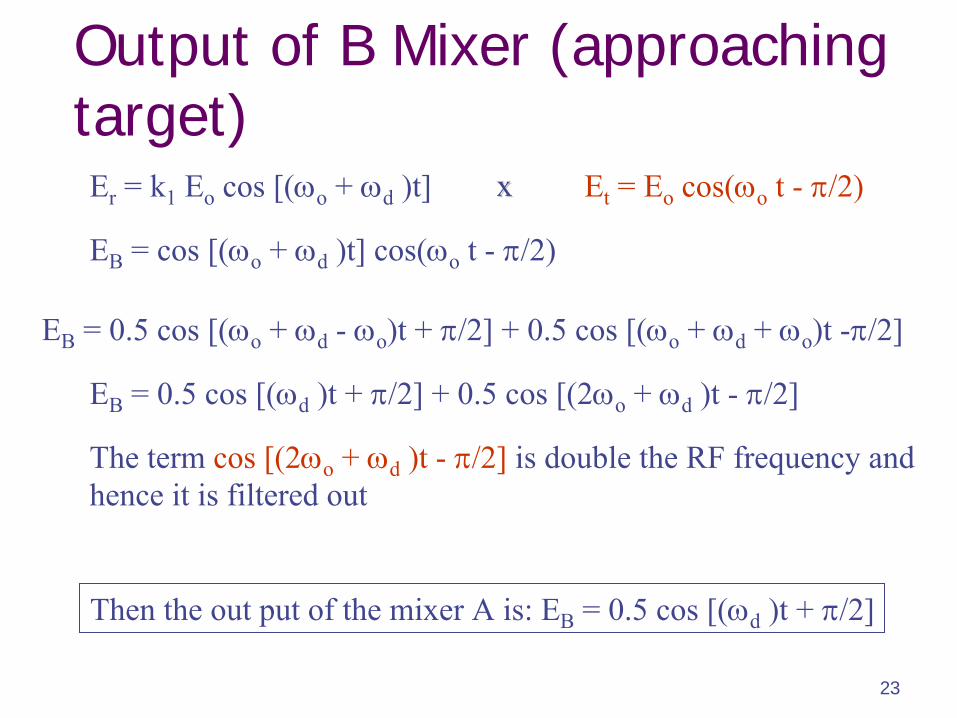
Output of B Mixer (approaching target)
EB
= cos [(o
+ d
)t] cos(o
t -
/2)
EB
= 0.5 cos [(o
+ d
-
o
)t + /2] + 0.5 cos [(o
+ d
+ o
)t -/2]
EB
= 0.5 cos [(d
)t + /2] + 0.5 cos [(2o
+ d
)t -
/2]
The term cos [(2o
+ d
)t -
/2]
is double the RF frequency and hence it is filtered out
Then the out put of the mixer A is: EB
= 0.5 cos [(d
)t + /2]
Et
= Eo
cos(o
t -
/2)xxEr
= k1
Eo
cos [(o
+ d
)t]
24
FM - CW Radar Systems
25
FM- CW Radar SystemsCW Radar Systems do not give target range information.
Doppler frequency is zero for stationary targets.
A version of CW Radar provides range information by incorporating Frequency Modulation (FM) technique.
FM-CW Radar can employ linear or non-linear frequency modulation.
Linear Modulation is achieved by Triangular modulating waveform, while Non-Linear Modulation is achieved by Sinusoidal modulating waveform.
26
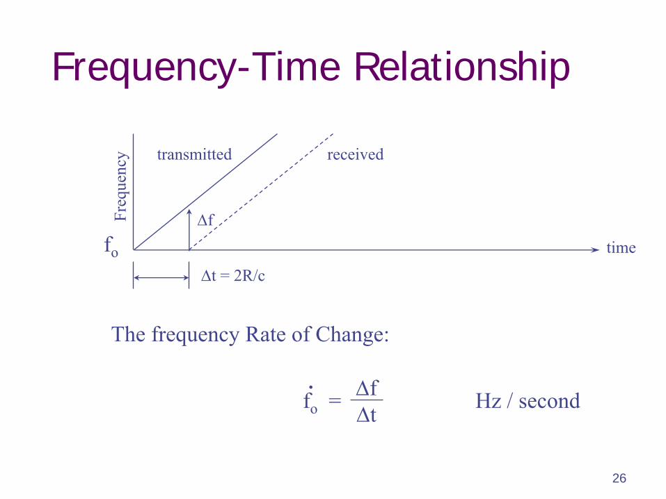
Frequency-Time Relationship
t = 2R/c
time
Freq
uenc
y
f
transmitted received
The frequency Rate of Change:
Hz / secondftfo
=.
fo
27
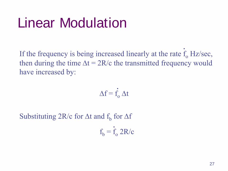
Linear Modulation
If the frequency is being increased linearly at the rate fo
Hz/sec,then during the time t = 2R/c the transmitted frequency would have increased by:
.
fb
= fo
2R/c .
f = fo
t.
Substituting 2R/c for t and fb
for f
28
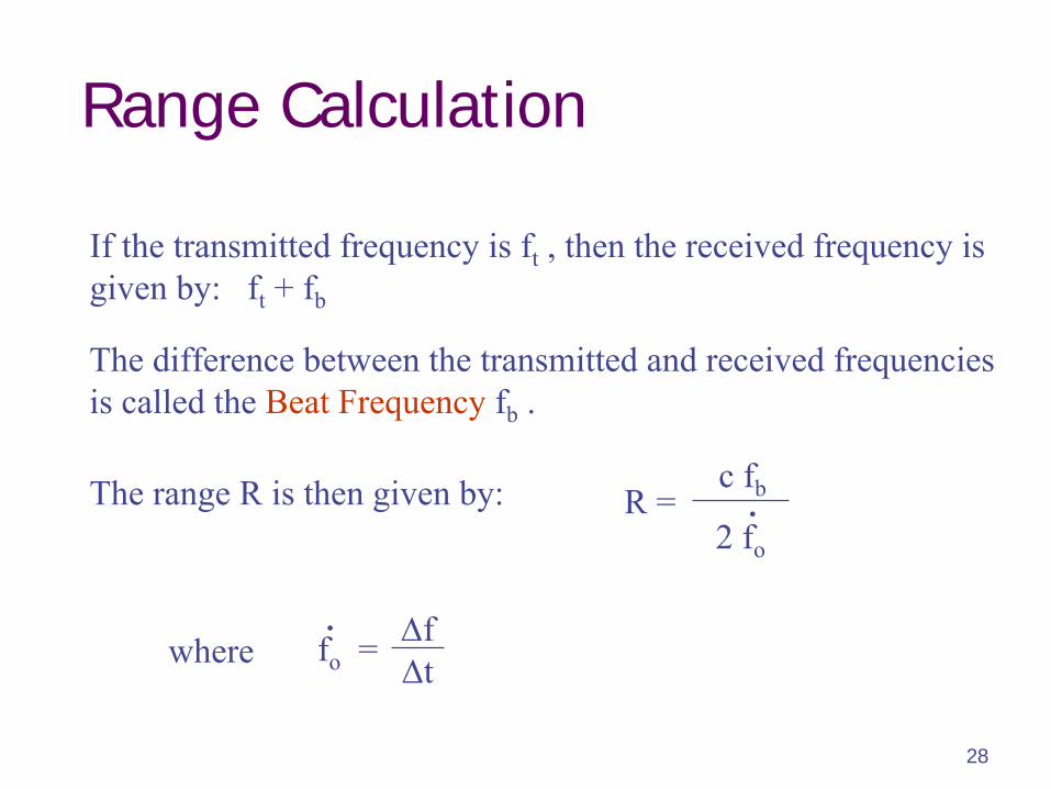
Range Calculation
If the transmitted frequency is ft
, then the received frequency is given by: ft
+ fb
The range R is then given by:
The difference between the transmitted and received frequencies is called the Beat Frequency
fb
.
ftfo
=.
2 fo
.c fbR =
where
29
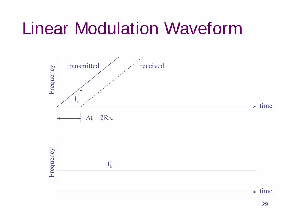
Linear Modulation Waveform
t = 2R/c
time
time
Freq
uenc
yFr
eque
ncy
fr
fb
transmitted received
30
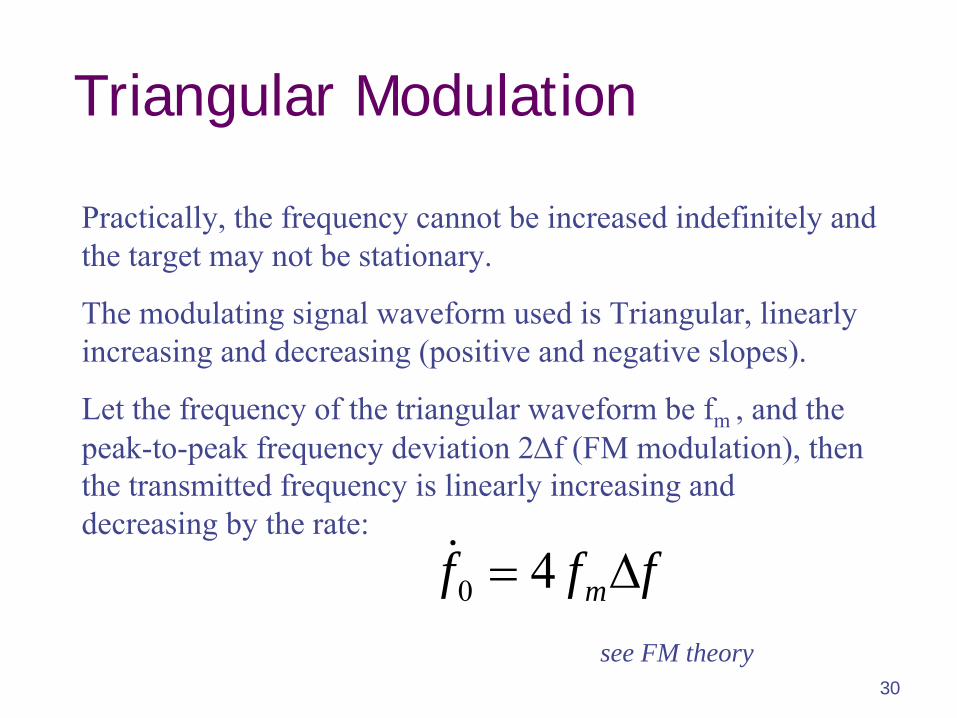
Triangular Modulation
Practically, the frequency cannot be increased indefinitely and the target may not be stationary.
The modulating signal waveform used is Triangular, linearly increasing and decreasing (positive and negative slopes).
Let the frequency of the triangular waveform be fm , and the peak-to-peak frequency deviation 2f (FM modulation), then the transmitted frequency is linearly increasing and decreasing by the rate:
see FM theory
fff m 40
31
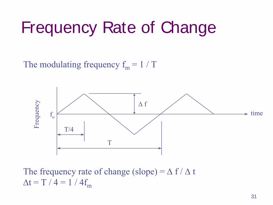
Frequency Rate of Change
time
Freq
uenc
y
fo
f
T
T/4
The modulating frequency fm
= 1 / T
The frequency rate of change (slope) =
f /
tt = T / 4 = 1 / 4fm
32
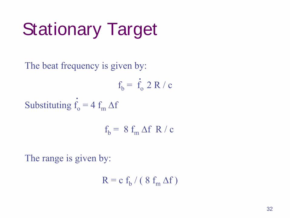
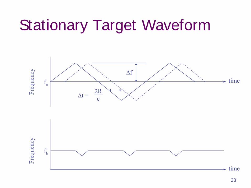
Stationary Target
fb
= fo 2 R / c
fb
= 8 fm
f R / c
.
R = c fb
/ ( 8 fm
f )
The beat frequency is given by:
Substituting fo
= 4 fm
f
The range is given by:
.
33
Stationary Target Waveform
2Rc
time
time
Freq
uenc
yFr
eque
ncy
fb
fo
t =
f
34
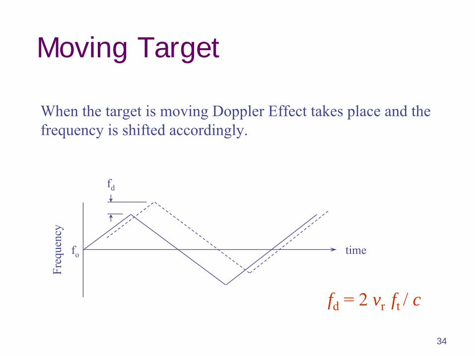
Moving Target
When the target is moving Doppler Effect takes place and the frequency is shifted accordingly.
time
Freq
uenc
y
fd
fo
fd
= 2 vr ft / c
35
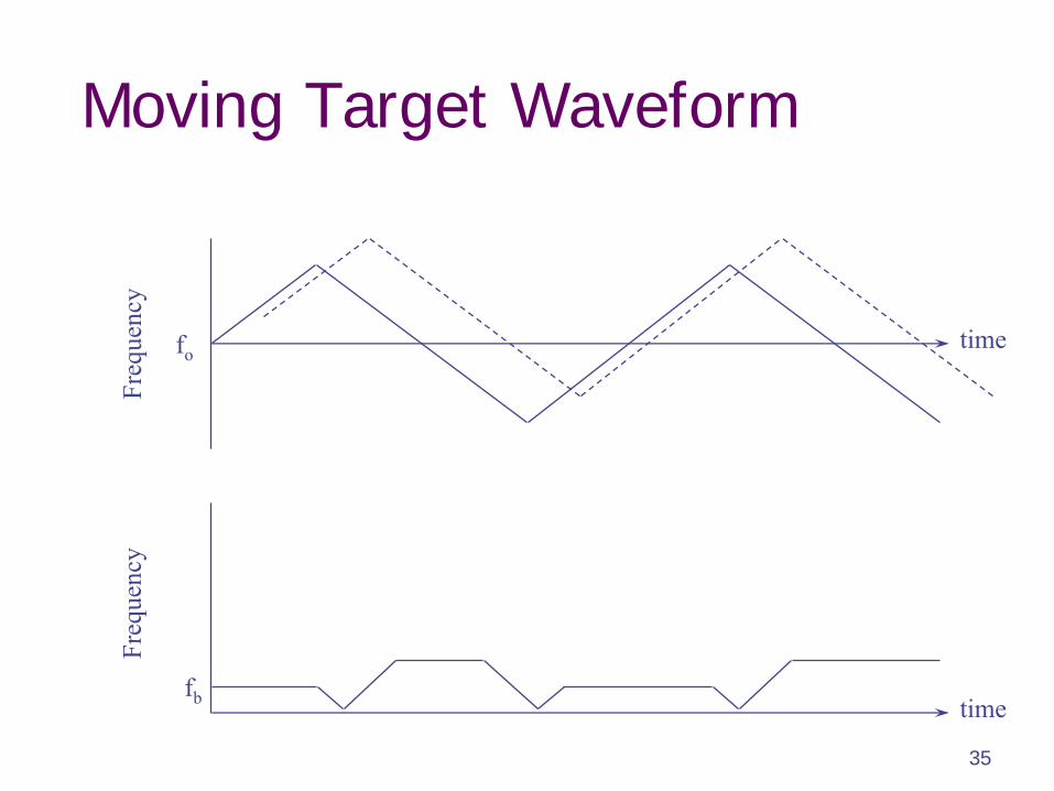
Moving Target Waveform
time
time
Freq
uenc
yFr
eque
ncy
fo
fb
36
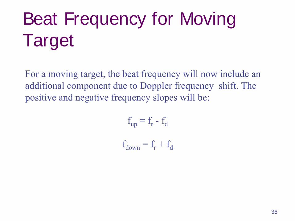
Beat Frequency for Moving Target
For a moving target, the beat frequency will now include an additional component due to Doppler frequency shift. The positive and negative frequency slopes will be:
fup
= fr
- fd
fdown
= fr
+ fd
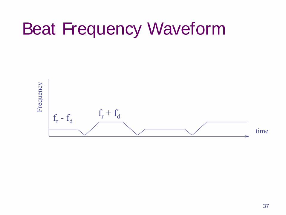
37
Beat Frequency Waveform
time
Freq
uenc
y
fr
- fdfr
+ fd
38
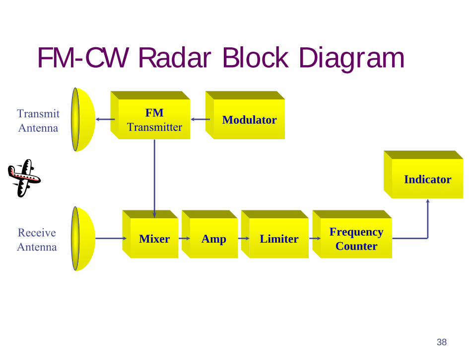
FM-CW Radar Block Diagram
Modulator
Mixer
TransmitAntenna
ReceiveAntenna
FMTransmitter
Limiter FrequencyCounter
Indicator
Amp

39
MTI & Pulsed Doppler Radar System

40
IntroductionSo far we examined the functionality of a number of radar systems, Pulsed Radar, CW Radar, and FM-CW Radar Systems.
Pulsed Radar System provides range (distance) information.
Doppler CW Radar System provides the relative velocity of a moving object.
FM-CW Radar System provides range information.
Is it possible to obtain both range and velocity of a moving object using one radar system?
41
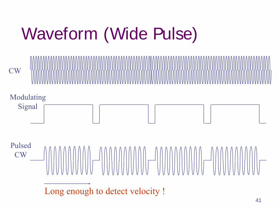
Waveform (Wide Pulse)
CW
ModulatingSignal
PulsedCW
Long enough to detect velocity !
42
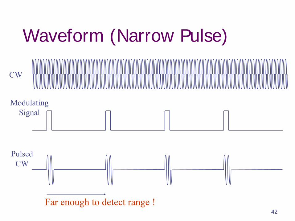
Waveform (Narrow Pulse)
CW
ModulatingSignal
PulsedCW
Far enough to detect range !

43
Waveform (Medium Pulse)
CW
ModulatingSignal
PulsedCW
Good enough to detect both range and velocity !
44
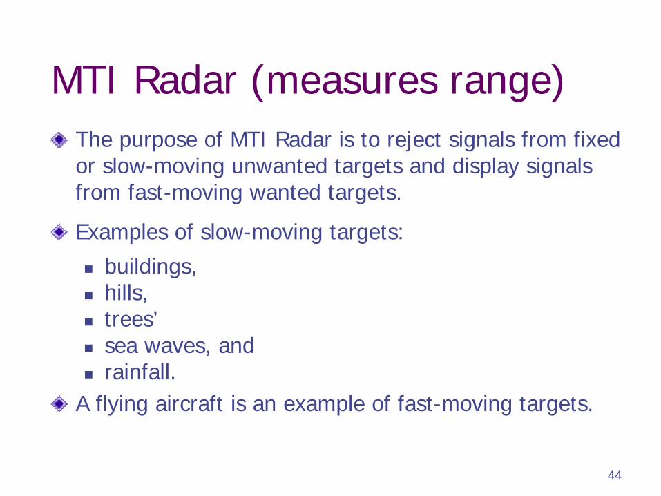
MTI Radar (measures range)The purpose of MTI Radar is to reject signals from fixed or slow-moving unwanted targets and display signals from fast-moving wanted targets.
Examples of slow-moving targets:
buildings,
hills,
trees’
sea waves, and
rainfall.A flying aircraft is an example of fast-moving targets.
45
Pulsed Doppler Radar (measures velocity)
Optimised for speed measurement, the range need not be accurate.
Pulsed Doppler Radar operates with unambiguous Doppler measurement but with ambiguous range measurement.
46
Purpose & Characteristics
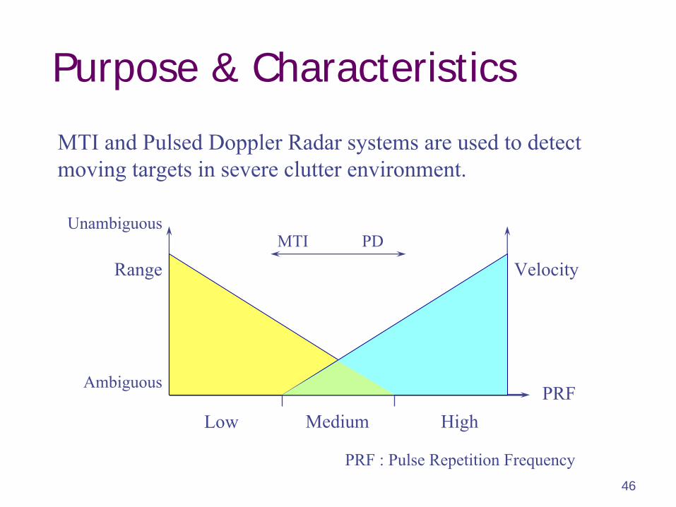
MTI and Pulsed Doppler Radar systems are used to detect moving targets in severe clutter environment.
Low Medium HighPRF
Range Velocity
Ambiguous
Unambiguous
PRF : Pulse Repetition Frequency
MTI PD
47
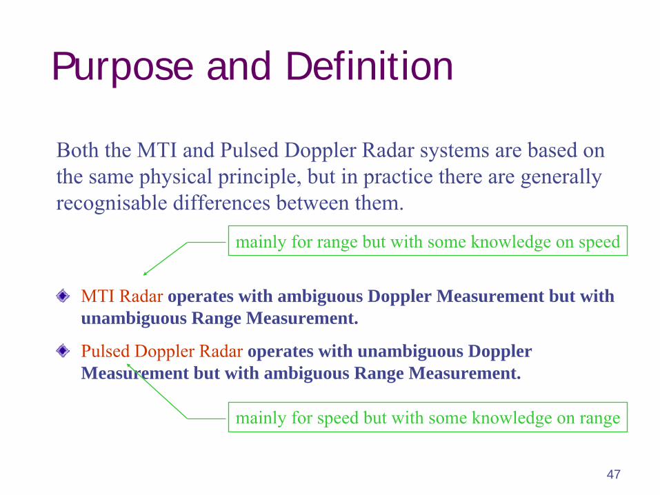
Purpose and Definition
MTI Radar
operates with ambiguous Doppler Measurement but with unambiguous Range Measurement.
Pulsed Doppler Radar
operates with unambiguous Doppler Measurement but with ambiguous Range Measurement.
Both the MTI and Pulsed Doppler Radar systems are based on the same physical principle, but in practice there are generally
recognisable differences between them.
mainly for range but with some knowledge on speed
mainly for speed but with some knowledge on range
48
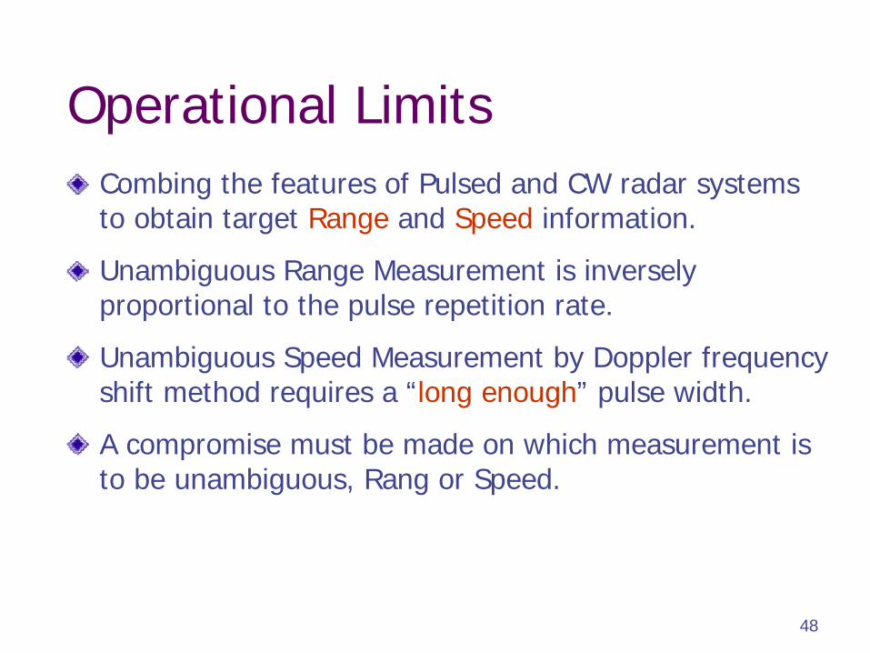
Operational LimitsCombing the features of Pulsed and CW radar systems to obtain target Range and Speed information.
Unambiguous Range Measurement is inversely proportional to the pulse repetition rate.
Unambiguous Speed Measurement by Doppler frequency shift method requires a “long enough” pulse width.
A compromise must be made on which measurement is to be unambiguous, Rang or Speed.
49
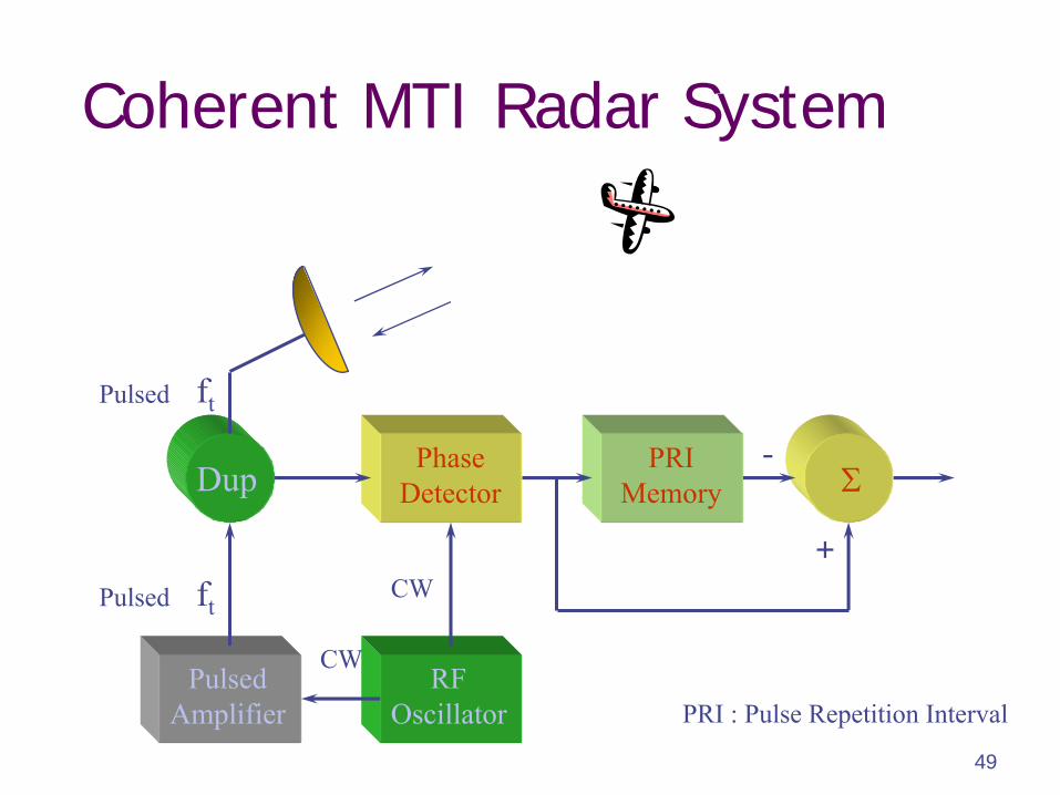
Coherent MTI Radar System
PhaseDetector
PRIMemory
-
+
RFOscillator
PulsedAmplifier
Dup
Pulsed
ft
ft
Pulsed
PRI : Pulse Repetition Interval
CW
CW
50
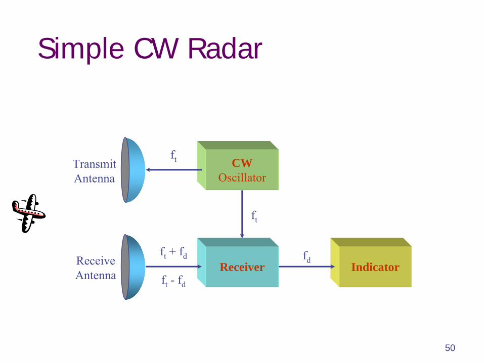
Simple CW Radar
TransmitAntenna
ReceiveAntenna
CWOscillator
IndicatorReceiverfd
ft
ft
+ fd
ft
- fd
ft
51
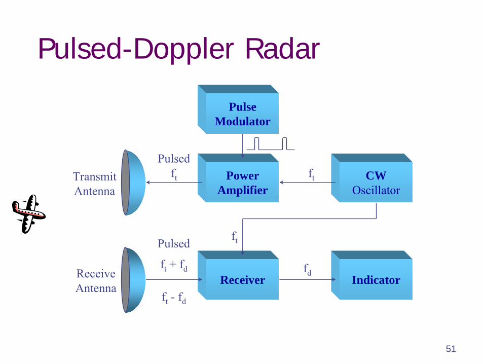
Pulsed-Doppler Radar
PulseModulator
TransmitAntenna
ReceiveAntenna
PowerAmplifier
IndicatorReceiver
CWOscillator
ft
+ fd
ft
- fd
Pulsedft
fd
ft
ft
Pulsed
52
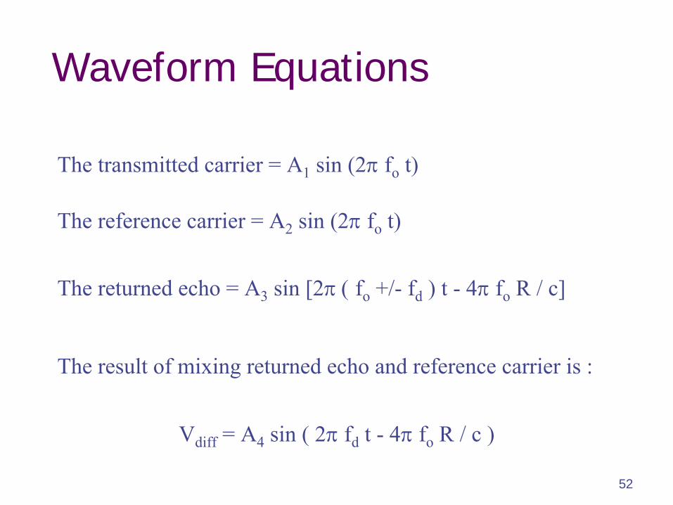
Waveform Equations
The transmitted carrier = A1
sin (2fo
t)
The reference carrier = A2
sin (2fo
t)
The returned echo = A3
sin [2fo
+/-
fd
) t -
4
fo
R / c]
The result of mixing returned echo and reference carrier is :
Vdiff
= A4
sin ( 2fd
t -
4
fo
R / c )