Dopants Promoting Ferroelectricity in Hafnia: Insights ... · Abstract Although dopants have been...
24
Dopants Promoting Ferroelectricity in Hafnia: Insights From A Comprehensive Chemical Space Exploration Rohit Batra, Tran Doan Huan, George A. Rossetti, Jr., and Rampi Ramprasad * Department of Materials Science & Engineering, University of Connecticut, Storrs, CT, USA E-mail: [email protected] 1 arXiv:1707.04211v1 [cond-mat.mtrl-sci] 13 Jul 2017
Transcript of Dopants Promoting Ferroelectricity in Hafnia: Insights ... · Abstract Although dopants have been...

Dopants Promoting Ferroelectricity in Hafnia:
Insights From A Comprehensive Chemical Space
Exploration
Rohit Batra, Tran Doan Huan, George A. Rossetti, Jr., and Rampi Ramprasad∗
Department of Materials Science & Engineering, University of Connecticut, Storrs, CT,
USA
E-mail: [email protected]
1
arX
iv:1
707.
0421
1v1
[co
nd-m
at.m
trl-
sci]
13
Jul 2
017

Abstract
Although dopants have been extensively employed to promote ferroelectricity in
hafnia films, their role in stabilizing the responsible ferroelectric non-equilibrium Pca21
phase is not well understood. In this work, using first principles computations, we
investigate the influence of nearly 40 dopants on the phase stability in bulk hafnia
to identify dopants that can favor formation of the polar Pca21 phase. Although no
dopant was found to stabilize this polar phase as the ground state, suggesting that
dopants alone cannot induce ferroelectricity in hafnia, Ca, Sr, Ba, La, Y and Gd were
found to significantly lower the energy of the polar phase with respect to the equilibrium
monoclinic phase. These results are consistent with the empirical measurements of
large remnant polarization in hafnia films doped with these elements. Additionally,
clear chemical trends of dopants with larger ionic radii and lower electronegativity
favoring the polar Pca21 phase in hafnia were identified. For this polar phase, an
additional bond between the dopant cation and the 2nd nearest oxygen neighbor was
identified as the root-cause of these trends. Further, trivalent dopants (Y, La, and Gd)
were revealed to stabilize the polar Pca21 phase at lower strains when compared to
divalent dopants (Sr and Ba). Based on these insights, we predict that the lanthanide
series metals, the lower half of alkaline earth metals (Ca, Sr and Ba) and Y as the most
suitable dopants to promote ferroelectricity in hafnia.
2

Introduction
Intentionally added impurities, i.e., dopants, can completely alter the physical properties
of the host material. While in some cases, the additional electrons or holes contributed
by the dopants dramatically modify the electronic structure, thereby changing properties
like the electrical conductivity1 and magnetism,2 in other cases, the small doping-induced
perturbation is enough to alter the atomic arrangement (crystal structure) of the host system
(e.g. yttrium stabilized zirconia). Hafnia (HfO2), a well known linear dielectric material,3–7
is likely an example of the latter, as doped thin films of this material have been recently
observed to exhibit ferroelectric (FE) behavior through the formation of a non-equilibrium
polar phase.8,9 Despite a great number of experimental and theoretical studies,10–13 the
origin of this novel functionality, which has applications in FE-field effect transistors14 and
FE-random access memories,15 has not been completely understood.
In the most likely mechanism, some “suitable” combination of surface energy, mechanical
stresses, oxygen vacancies, dopants and the electrical history of the hafnia film is believed to
stabilize the polar orthorhombic Pca21 (P-O1) phase over the equilibrium monoclinic (M)
phase of hafnia, thus enabling FE behavior.16–19 The disappearance of ferroelectricity in
the absence of a capping electrode and with increasing film thickness suggests the critical
role of the mechanical stresses8,20–24 and surface energies,11–13respectively. Similarly, the
demonstration of the “wake-up effect” (on application of external electric fields) hints at the
role that the electrical history of the film plays in stabilizing the FE phase.25–27 Dopants,
too, have been found to increase the stability “window” of the P-O1 phase as reflected in an
increase in both the magnitude of the measured polarization and the critical thickness of the
hafnia film (below which FE behavior is observed).9 Some insight into the role of dopants
has emerged from recent empirical studies,17,18 which have indicated the trend of dopants
with higher ionic radii leading to enhanced polarization. Nevertheless, the true role of the
dopants in the formation of the P-O1 phase remains unclear, given that traditionally doping
is known to stabilize the high-temperature tetragonal (T) or the cubic phases of hafnia.28–30
3

Two critical questions, important from both application and theoretical standpoints, that
these recent studies8,18,23,24,31 on FE doped hafnia raise are: (1) which dopant favor the
polar phase the most and at what concentration?, and (2) do dopants play a critical role in
stabilizing this polar phase in hafnia films, and if yes, which attributes of a dopant (chemical
or physical) are relevant?
Stag
e 1
Stag
e 2
Stag
e 3
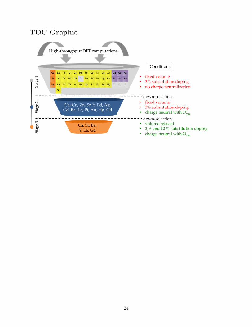
• fixed volume• 3% substitution doping• no charge neutralization
Conditions
down-selection
down-selection
Ca, Cu, Zn, Sr, Y, Pd, Ag, Cd, Ba, La, Pt, Au, Hg, Gd
Ca, Sr, Ba,Y, La, Gd
High-throughput DFT computations
• fixed volume• 3% substitution doping• charge neutral with Ovac
• volume relaxed• 3, 6 and 12 % substitution doping• charge neutral with Ovac
Gd
Figure 1: The overall scheme of this work illustrating the three-stage selection process andthe modeling conditions imposed in each stage.
In this contribution, we address these questions using high-throughput first-principles
density functional theory (DFT) computations. In order to address the first question, we
follow a three-stage down-selection strategy, illustrated in Fig. 1, wherein we examine the
influence of nearly 40 dopants on the energetics of the relevant low-energy phases of hafnia,
including M (P21/c), T (P42/nmc), P-O1 (Pca21), another polar P-O2 (Pmn21), and high-
pressure OA (Pbca) phases. Based on these energy changes, the initial set of nearly 40
dopants in Stage 1 is down-selected to 14 dopants in Stage 2, and finally, to the 6 most
promising dopants, i.e., Ca, Sr, Ba, Y, La and Gd, in Stage 3. In agreement with empirical
observations,17,18 our study revealed that these 6 dopants favor the stabilization of the P-O1
phase of hafnia. To answer the second question, the computational data obtained in Stage
4

3 was analyzed. Clear trends illustrating that dopants with higher ionic radii and lower
electronegativity stabilize the P-O1 phase the most were found, also consistent with the
experimental observations.18 The root-cause of these trends is traced to the formation of
an additional bond between the dopant and the 2nd nearest-neighbor oxygen atom. Based
on these findings, we search the entire Periodic Table, predicting the lanthanides, the lower
half of the alkaline earth metals (i.e. Ca, Sr, Ba) and Y as the most favorable dopants to
promote ferroelectricity in hafnia.
Theoretical Methods
Our work is based on electronic structure DFT calculations, performed using the Vienna
Ab Initio Simulation Package32 (VASP) employing the Perdew-Burke-Ernzerhof exchange-
correlation functional33 and the projector-augmented wave methodology.34 A 3×3×3 Monkhorst-
Pack mesh35 for k-point sampling was adopted and a basis set of plane waves with kinetic
energies up to 500 eV was used to represent the wave functions. For each doped phase, spin
polarized computations were performed and all atoms were allowed to relax until atomic
forces were smaller than 10−2 eV/A.
To determine the energy ordering of phases in doped hafnia, we define the relative energy
of a phase α with respect to the equilibrium M phase in the presence of a dopant D as
∆Eα−MD = Eα
D − EMD , (1)
where EαD and EM
D are the DFT computed energies of the doped α and M phases, respectively.
To highlight the direct role of a dopant in stabilizing the phase α, we subtract from Eq. 1 a
term corresponding to the energy of dopant-free pure phases:
∆Eα−MD−Pure =
(Eα
D − EMD
)−(Eα
Pure − EMPure
)(2)
5

where EαPure and EM
Pure are the DFT computed energies of pure α and M phases, respectively.
∆Eα−MD−Pure represents the change in the relative energy of the phase α with respect to the M
phase solely due to the introduction of the dopant D. Thus, a dopant with negative ∆Eα−MD−Pure
favors (or stabilizes) the phase α over the M phase more than in the dopant-free pure case.
Further, if α happens to be one of the polar phases, one can expect such dopants to enhance
FE behavior in hafnia.
Five different phases of hafnia were considered, including M, T, P-O1, P-O2 and OA, as
they were either empirically observed or theoretically predicted to have low energy under
conditions for which hafnia films display FE behavior.10,36 Equivalent 32 formula-unit (96
atom) supercells, starting from the structures documented in our previous work,20 were
constructed to carry out the energy calculations. For each phase, three levels of substitutional
doping concentration, namely, 3.125%, 6.25% and 12.5% were studied by replacing 1, 2 and
4 Hf atom(s), respectively, by the dopant atom(s).
To overcome the challenge of high computational cost associated with accurately mod-
eling the effect of ∼40 dopants on the energetics of the five phases of hafnia, we carry
out this work in three stages, as illustrated in Fig. 1. Moving down the stages, a bal-
ance between computational accuracy and cost is maintained by increasing the modeling
sophistication on the one hand and retaining only the promising dopants, with substantially
negative ∆EPO1−MD−Pure and ∆EPO2−M
D−Pure , on the other hand. We restrict the initial set of dopants
to elements from row 3, 4 and 5 of the Periodic Table (see Fig. 1), with the exception
of Gd, which is included since empirical observations of ferroelectricity have been made in
this case. In Stage 1, we model these dopants in the aforementioned five phases at 3.125%
doping concentration, and under the assumption of fixed volume of the simulation cell and
the absence of oxygen vacancies (Ovac). The relatively large size of the dopants considered
and small perturbations expected at such small doping concentration form the rationale un-
derlying these assumptions. Promising dopants from Stage 1 that energetically favor the
polar phases were selected for more in-depth studies in Stage 2. Their influence on the phase
6

stability was again studied at the doping concentration of 3.125%, but now in a presence of
appropriate concentration of Ovac (determined through the study of the electronic structures
of doped hafnia phases, as discussed in Supplementary Information), expected to be present
in real systems owing to the different oxidation states of the dopant and the hafnium ion.
Finally, in Stage 3, promising dopants selected from Stage 2 were studied at multiple doping
concentrations of 3.125%, 6.25% and 12.5%. The volume of the supercell was relaxed and an
appropriate number of Ovac were introduced to achieve charge neutrality. The doped hafnia
structures obtained in Stage 3 were later examined to draw key chemical trends.
Results and Discussion
Stage 1
As stated above and illustrated in Fig. 1, the influence of ∼40 dopants on the phase stability
in hafnia under the assumption of fixed volume and the absence of Ovac was studied in Stage
1. The energies of different phases of hafnia at 3.125% doping concentration are presented
in Fig. 2 and are found to be consistent with limited available past studies (shown in open
circles).10,28 In case of pure hafnia, the small energy difference between the equilibrium M
and the P-O1 phases should be noted, signaling that even minor perturbations, perhaps in-
troduced by extrinsic factors, such as dopants, stresses, etc., may be sufficient to stabilize the
polar P-O1 phase as the ground state. Further, the P-O1 and the OA phases are extremely
close in energy, in agreement with the previous studies.10,11,37 This energetic proximity is a
manifestation of the remarkable structural similarity between the two phases.
As captured in Fig. 2(a), the M phase remains the equilibrium phase for all the dopants
considered at 3.125% doping concentration, although the energy differences among the hafnia
phases change significantly. The relative energy of T phase alters substantially more with
the choice of the dopant (for e.g., Ge, Au, etc.) in comparison to that of the P-O1, P-O2 and
OA phases, possibly due to the different coordination environment experienced by a dopant
7

Pure Ca Sc Ti V Cr
Mn Fe Co Ni
Cu
Zn
Ga
Ge
As Sr Y Zr
Nb
Mo
Ru
Rh
Pd Ag
Cd In Sn Sb Ba La Ta W Re
Os Ir Pt Au
Hg
Gd
0
50
100
150
200∆
Eα−
MD
(meV
/f.u
.)III Row IV Row V Row(a)
3.125 % doping
T
P-O2
P-O1
OA
M
Pure Ca Sc Ti V Cr
Mn Fe Co Ni
Cu
Zn
Ga
Ge
As Sr Y Zr
Nb
Mo
Ru
Rh
Pd Ag
Cd In Sn Sb Ba La Ta W Re
Os Ir Pt Au
Hg
Gd
−30
−20
−10
0
10
20
30
∆E
α−
MD−
Pur
e(m
eV/f
.u.)
III Row IV Row V Row(b)
3.125 % doping
M
T
P-O1
P-O2
OA
Figure 2: Phase stability of hafnia in presence of different dopants and under the constraintsof Stage 1, as computed using (a) Eq. 1 and (b) Eq. 2. In panel (a), solid symbols representthe data from this work while open symbols signify results from previous studies.10,28 Thelines are guide to the eyes.
cation in the T (CN = 8) versus the other phases (CN = 7) considered here. Interestingly,
the T phase of Pd- and Pt-doped hafnia collapse into the P-O1 phase (see Supplementary
Information for details) upon atomic relaxation (resulting in absence of these data points
in Fig. 2). An important implication of this finding is that even small perturbations can
possibly result in T to P-O1 phase transformations, and can be a potential pathway of
formation of the P-O1 phase in hafnia. We will continue to encounter this collapse of the T
phase to the P-O1 phase in later stages of this work as well.
Owing to the large energy scale and the small doping level, the influence of dopants on
the phase stability appears feeble in Fig. 2(a). This picture, however, changes substantially
when we re-plot it using Eq. 2 as shown in Fig. 2(b). We again caution here that the quantity
8

∆Eα−MD−Pure plotted in Fig. 2(b) only helps us identify the phase(s) a dopant prefers over the
M phase, and not the lowest energy ground state of hafnia, which is indeed determined by
the quantity ∆Eα−MD . Two key trends to be observed in Fig. 2(b) are: (1) row IV and
row V dopants follow very similar phase stability trends when moving from left to right
across the periodic table, with the row V dopants inducing larger energy variations, and
(2) dopants from alkaline earth, and group 3, 10, 11 and 12 of the periodic table tend
to favor the P-O1 and/or the P-O2 phases in hafnia, leading to the following shortlisted
candidates further studied in Stage 2: Ca, Sr, Ba, Y, La, Cu, Zn, Pd, Ag, Cd, Pt, Au, Hg
and Gd. Interestingly, a few of these dopants, such as Y, La, Sr, Ba, La, among others,
have been empirically17,18 shown to promote substantial FE behavior in hafnia films, thus,
already highlighting an agreement between our initial results and experiments. Another vital
chemical insight, which will be strengthened in the later sections, is that dopants with low
electronegativity tend to stabilize the polar phases in hafnia.
Stage 2
In Stage 2, we increase the modeling sophistication by introducing appropriate charge neu-
tralizing Ovac for 3.125% doped hafnia systems. Two issues concerning the number of Ovac
and their placement site in the 32 hafnia-unit supercell should be addressed. Since all the
dopants, except Y, La, Au and Gd, in Stage 2 are divalent, only one Ovac corresponding to
the one dopant cation needs to be added (as confirmed using the electronic structure studies
discussed in Supplementary Information). However, for the case of Y, La, Au and Gd, a par-
tial Ovac is required at 3.125% doping level. To avoid practical computational issues, these
trivalent dopants were transferred directly to Stage 3. The remaining 10 divalent dopants
were studied in Stage 2 with a single Ovac.
With respect to the placement of this single Ovac, we argue that this should be in a
nearest-neighbor site to the dopant cation owing to the electrostatic pull expected between
the negatively charged dopant and the positively charged Ovac defects. With this restriction
9

on configurational space to the cases in which Ovac is closest to the dopant, and taking into
account the symmetry of the different hafnia phases, we are left with 7 different choices for
the M, P-O1, and OA phases, 5 for the O2 and 2 for the T phase. These choices can be
further classified into two categories based on the number of Hf-O bonds that need to be
broken to introduce an Ovac; while one category involves breaking 3 bonds, the other requires
4 broken bonds. For the representative case of Pd- and Pt- doped hafnia systems, energies
for all possible configurations (i.e., 7 for the M, P-O1, and OA, 5 for the O2 and 2 for the T)
were computed and it was found that Ovac sites involving 3 broken Hf-O bonds are always
energetically preferred, with the exception of the T phase which has only one type of Ovac
site that involves breaking 4 Hf-O bonds. Thus, we further reduce our configurational space
to cases which involve breakage of only 3 Hf-O bonds in the M, P-O1, OA and P-O2 phases.
This leaves us with 3 different choices for the M, P-O1, OA phases, and 2 choices for each
of the O2 and T phases. For each phase, only the configuration with lowest energy was
considered in order to obtain the phase stability trends presented in Fig. 3. To summarize,
in Stage 2 we computed the phase stability of hafnia at dopant concentration of 3.125% for
the case of the 10 shortlisted divalent elements, and with the restrictions of Ovac being in
nearest-neighbor site of the dopant and occupying an O site with 3 Hf-O bonds in the case
of M, P-O1, OA and O2 phases. The volume of the supercell was also assumed to be fixed.
Pure Ca Sc Ti V Cr
Mn Fe Co Ni
Cu
Zn
Ga
Ge
As Sr Y Zr
Nb
Mo
Ru
Rh
Pd Ag
Cd In Sn Sb Ba La Ta W Re
Os Ir Pt Au
Hg
Gd
−60
−40
−20
0
20
40
∆E
α−
MD−
Pur
e(m
eV/f
.u.)
III Row IV Row V Row
3.125 % doping Mvac Tvac P-O2vac OAvac P-O1vac
Figure 3: The relative energies of 3.125% doped hafnia for the limited set of 10 divalentdopants of Stage 2 in presence of a charge neutralizing Ovac. For ease of comparison, theresults of Stage 2 (open symbols) are overlaid on top of that of Stage 1 (lighter solid symbols).
10

The findings of Stage 2 are overlaid on the results of Stage 1 for the selected set of 10
divalent dopants in Fig. 3. The transition metals that favored the polar phase(s) in Stage 1,
do not substantially stabilize the polar phase(s) with the introduction of Ovac as ∆Eα−MD−Pure
of both the polar phases can be seen to shift up after the Ovac introduction (e.g., compare
the open and solid symbols for the case of Cu and Zn in Fig. 3). On the other hand, the T
phase is consistently favored with the addition of Ovac due to the lowering of the coordination
number of the vacancy neighboring Hf atoms from 8 to 7, which is energetically preferred -
and is also the reason why the M phase is the equilibrium phase of hafnia. This behavior
is consistent with the past study.38 The Cu- and Ag-doped T phase was, however, found
to collapse into the polar P-O1 phase. Further investigations are necessary to identify what
triggers this collapse of the T phase into the P-O1 phase. Nevertheless, the alkaline earth
metals like Ca, Sr, and Ba continue to stabilize the polar phases in Stage 2, leaving us with
our next set of promising candidates studied in Stage 3, i.e, Ca, Sr, Ba, Y, La, Au and Gd.
Stage 3
From the initial set of ∼40 dopants, we are now left with the 7 most promising candidates in
Stage 3 that favor the polar phase(s) in hafnia. Owing to the lesser number of dopants in-
volved, we now lift the modeling constraints imposed in the previous stages, and investigate
the influence of these dopants at varying concentrations. For the case of divalent dopants,
we studied three different doping concentrations of 3.125%, 6.25% and 12.5%. On the other
hand, for the case of trivalent dopants, we studied only 6.25% and 12.5% doping concen-
trations owing to the difficulty associated with modeling a partial Ovac at 3.125% doping
level, as mentioned earlier. The volume of the supercell was relaxed and an appropriate
number of Ovac were introduced to achieve charge neutrality. Unfortunately, for the case of
Au, the phases did not retain their structural identity (i.e., the relaxed structures from our
computations were so distorted that they could not be unambiguously associated with the
starting structure) at higher doping concentration of 6.25% and 12.5%, and thus, we exclude
11

this case from our results.
−50
0
50
100
150
∆E
α−
MD
(meV
/f.u
.) Ca (a) Sr (b)
M P-O2 OA T P-O1
Ba (c)
0 3 6 12% doping conc.
−50
0
50
100
150
∆E
α−
MD
(meV
/f.u
.) Y (d)
0 3 6 12% doping conc.
La (e)
0 3 6 12% doping conc.
Gd (f)
Figure 4: Phase stability of hafnia in presence of (a) Ca, (b) Sr, (c) Ba, (d) Y, (e) La, and(f) Gd, as function of their doping concentration. While the phases mostly retained theirstructural identity upon doping (solid symbols), in some limited cases, especially at higherdoping concentration, it was hard to clearly identify the doped phases upon relaxation. Suchcases are represented in open symbols based on their starting phase.
The results of Stage 3 are presented in Fig. 4. We first note that while in many cases
the doped hafnia phases retained their structural identity upon relaxation, there were a few
cases, especially at 12.5% doping concentration, where either it was difficult to clearly iden-
tify the doped phases or the starting phase transformed into another phase upon relaxation.
We represent these unusual cases in open symbols based on their starting structure. The
following key observations can be made from Fig. 4: (1) all of the Stage 3 dopants stabi-
lize the P-O1 and/or the P-O2 phases with increasing doping concentration, (2) while at
3.125% doping level, there exists substantial energy difference between the polar phases and
the equilibrium M phase, at 6.25% doping level, the P-O1 phase becomes extremely close
in energy to that of the M phase, (3) at high doping concentration of 12.5% no conclusive
12

statements about the ground state of hafnia can be made as hafnia phases loose their struc-
tural identity at such high doping level, (4) for some doped cases, the T and even the P-O2
phase collapsed into the P-O1 phase upon relaxation, suggesting that these dopants prefer
to form the relatively low energy polar P-O1 phase, and (5) between the two polar phases
considered, i.e., P-O1 and P-O2, the former is clearly favored over the latter, consistent with
the experimental observations of this phase.19
One important limitation/assumption of the above study pertaining to the dopant and
Ovac arrangement should be mentioned here. Higher doping concentration (6.25% and 12.5%)
leads to a rather challenging modeling problem of expansion of the configurational space. For
instance, for the case of 6.25% Sr-doped hafnia, the two Sr atoms would lie on any two sites
of the cation sub-lattice and the associated two Ovac on any two sites of the anion sub-lattice.
Even after discounting for the symmetry of the system, a huge number of such permuta-
tions (or configurations) are possible and it is not at all trivial to determine which among
them would be energetically preferred. Further, to finally determine the phase stability of
doped hafnia, one would have to ascertain the lowest energy configuration of each phase.
Although methods, such as, cluster expansion,39 etc., can be used to surmount this problem
of large configurational space, these approaches are extremely computationally demanding.
Nevertheless, we get some estimate of the scale of energy variations expected in our doped
hafnia systems owing to the different possible configurations by computing energies of 10
diverse configurations of 6.25% Sr-doped P-O1 phase at various dopant-dopant distances. A
standard deviation of just ∼8 meV/f.u. in the energies of these configurations was found,
suggesting that the scale of energy variations owing to different possible configurations of
dopants is rather small as compared to that of the relative energies among the different
phases of hafnia. Thus, we expect the trends observed in the Fig. 4 and the conclusions
made in the previous discussion to hold even when multiple possible configurations of doped
hafnia phases are considered.
The results from Fig. 4 clearly suggest that certain dopants, especially Ca, Sr, Ba, La, Y,
13

and Gd can substantially lower the relative energy between the P-O1 and the equilibrium M
phases, although no situation was encountered in which a polar phase had the lowest energy.
This indicates that dopants alone cannot stabilize a polar phase as the ground state in hafnia
and can only assist other factors, such as the surface energy, the mechanical stresses and
the electric field, prevalent in the hafnia films, to form the polar phase. The disappearance
of FE behavior in the absence of the aforementioned crucial factors,16 and the empirical
observation of FE behavior in pure hafnia films9 further corroborates this conclusion.
Learning from the DFT data
−50
0
50
100
150
∆E
α−
MD
(meV
/f.u
.)
0.9 1.14 1.32 1.49
1.08
1.04
1.17
Increasing radii (A)
(a)
M-PureT-PureO1-Pure
M-D+2
T-D+2
O1-D+2
Increasing electronegativity1.31.00.950.89 1.2
1.22
1.1
M-D+3
T-D+3
O1-D+3
2.6
2.8
3.0
3.2
3.4
3.6
Dop
ant-
2ndne
ares
tOdi
stan
ce(A
)
Increasing radii (A)0.9 1.14 1.32 1.491.04
1.08 1.17
(b)Hf Ca Sr Ba
Gd
Y
La
HfCaSrBa Gd
Y
La Hf Ca Sr BaY
Gd La
Figure 5: (a) Chemical trends in the relative energies of the M, T and P-O1 phases of hafniawith (a) ionic radius and electronegativity of a divalent (solid symbols) and trivalent (opensymbols) dopant at 6.25% doping concentration. Some cases of the T phase collapsed intothe P-O1 phase upon relaxation and are omitted here for cleanliness. (b) The distancebetween the dopant and the closest 2nd nearest oxygen in the case of 6.25% doped P-O1and M phases.
In order to reveal the dominant attributes of a dopant that help stabilize a polar phase
in hafnia, we plot in Fig. 5(a) the relative energies of the most relevant M, T and P-O1
phases against the ionic radius40 and the electronegativity41 of the dopants in Stage 3 for
the case of 6.25% doping level. With the dopants grouped on the basis of their valency, a
clear chemical trend of dopants with higher ionic radius and lower electronegativity favoring
the polar P-O1 phase in hafnia is evident from the figure. The trend of increasing stability of
14

the polar Pca21 phase with increasing dopant radii matches very well with the experimental
observations18 of higher polarizations in hafnia systems with larger dopants. We further
note that trivalent dopants considered here, owing to their ionic radii being comparable to
that of Hf stabilizes the P-O1 phase at lower strains in comparison to that of the divalent
dopants. Thus, trivalent dopants seem to be a superior choice to promote ferroelectricity in
hafnia.
To understand the root-cause of the aforementioned chemical trends, the relaxed struc-
tures of the doped hafnia phases were carefully examined. In Fig. 5(b), we plot the distance
between the dopant and the closest 2nd nearest neighbor oxygen for the case of the M and
the P-O1 phases as a function of the ionic radii of the dopants considered in Stage 3. Al-
though this dopant-oxygen distance remains largely unaffected upon doping in the case of
the M phase (with the exception of the Ba doping), it substantially reduces in the case of
the P-O1 phase, suggesting formation of an additional dopant-oxygen bond. Further, as is
evident from the figure, this additional bond becomes consistently shorter for dopants with
larger ionic radii and lower electronegativity (not shown here). Cumulatively these obser-
vations strongly suggest formation of an energy lowering bond between the dopant cation
and the 2nd nearest oxygen neighbor in the case of the P-O1 phase as the root-cause of its
stabilization with respect to the M phase upon doping.
Based on the aforementioned findings and the observed chemical trends, we search the
entire Periodic Table to find dopants with low electronegativity and large ionic radii that will
potentially favor the polar Pca21 phase in hafnia. Excluding the elements studied in this
work and those which are radioactive, the lanthanide series elements emerge as good dopant
candidates matching these criteria. Thus, combining all the findings, results or observations
from our computations we finally predict that the lanthanide series elements, the lower half
of the alkaline earth metals (Ca, Sr and Ba) and Y are the most favorable dopants to promote
ferroelectricity in hafnia.
15

Connection with experiments
(a) (b)
Figure 6: Trends in the measured remnant polarization of doped hafnia films with (a) dopantionic radii and (b) doping concentration. The results are reproduced from Ref. 18 withpermission from The Royal Society of Chemistry.
Some noteworthy agreements between the theoretical predictions made in this study and
the empirical observations made by Starschich et al.18 (major results reproduced in Fig. 6)
and Schroeder et al.17 can also be drawn; (1) the dopants that showed substantial polarization
in the empirical studies, such as Sr, Ba, Gd, Y, La were also found to stabilize the polar
P-O1 phase significantly, (2) the trend of dopants of larger ionic radii stabilizing the polar
P-O1 phase matches well with the experimental observation of high remnant polarization in
larger dopants (see Fig. 6(a)), and (3) in agreement with the experiments, we also found that
the doping concentration of 6.25% to be most appropriate to stabilize the polar phase. As
reproduced in Fig. 6(b), with increasing doping concentration, the measured polarization in
hafnia films first increases, reaches a maxima around 5-8% doping level, and then gradually
decreases. Similar results are evident from this study as well. With increasing doping
concentration, the polarization would initially rise due to enhanced stabilization of the polar
P-O1 phase. However, after a critical doping concentration the distortions introduced in
the structure would diminish the polarization of the polar phase, thus, resulting in gradual
decrease in the measured polarization. Overall, the remarkable similarities between our
computations and empirical observations give confidence in the assumptions made to model
16
the hafnia systems and the predictions made in this study.
Conclusions
In summary, we investigated the influence of ∼40 dopants on the phase stability in hafnia
using density functional theory calculations. A three stage down-selection strategy was
adopted to efficiently search for promising dopants that favor the polar phases in hafnia. In
Stage 1, the selected dopants were modeled under the constraints of 3.125% substitutional
doping concentration, the absence of charge neutralizing oxygen vacancy, and fixed volume.
From this stage, 10 divalent and 4 trivalent dopants that favor the polar Pca21 and/or Pmn21
phase in hafnia were selected for Stage 2. While the trivalent dopants were studied directly
in next stage, the divalent dopants in Stage 2 were modeled in presence of an appropriate
oxygen vacancy, from which Ca, Sr and Ba were found to favor the polar Pca21 phase and
were selected to Stage 3.
In Stage 3, the remaining promising candidates, i.e., Ca, Sr, Ba, Y, La and Gd doped
hafnia systems were comprehensively studied at various doping concentrations with appro-
priate number of charge compensating oxygen vacancies. For all these dopants, increasing
doping concentration enhanced the stabilization of the polar Pca21 phase. However, no case
was encountered in which a polar phase becomes the ground state, suggesting that dopants
alone may not induce ferroelectricity in bulk hafnia and can only assist other factors such as
surface energy, strain, electric field, etc. Empirical measurements of relatively high remnant
polarization have been made for these identified dopants, suggesting good agreement be-
tween experiments and our computations. Indeed, the doping concentration of around 5-8%
at which maximum polarization is empirically observed matches well with our predictions.
Finally, clear chemical trends of dopants with higher ionic radii and lower electronega-
tivity favoring polar Pca21 phase in bulk hafnia were identified. For this polar phase, an
additional bond between the dopant cation and the 2nd nearest oxygen neighbor was iden-
17
tified as the root-cause of this observation. Further, trivalent dopants, owing to their ionic
radii being comparable to that of Hf, were found to favor the polar Pca21 phase at lower
strains in comparison to that of the divalent dopants. Based on these insights, we were able
to go beyond the dopant elements considered with the DFT calculations. We conclude that
the entire lanthanide series metals, the lower half of the alkaline earth metals (Ca, Sr, Ba)
and Y are the most favorable dopants to promote ferroelectricity in hafnia. These insights
can be used to tailor the ferroelectric characteristics of hafnia films by selecting dopants with
appropriate combination of ionic radius and electronegativity.
Acknowledgement
Financial support of this work through Grant No. W911NF-15-1-0593 from the Army Re-
search Office (ARO) and partial computational support through a Extreme Science and
Engineering Discovery Environment (XSEDE) allocation number TG-DMR080058N are ac-
knowledged.
Supporting Information Available
The following files are available free of charge. Discussion on the need of oxygen vacancy
introduction in doped hafnia using electronic structure studies and the methodology adopted
to characterize different phases of doped hafnia.
References
(1) Wilson, A. H. The Theory of Metals ; Cambridge University Press, 1965.
(2) Wang, Z. L. Zinc oxide nanostructures: growth, properties and applications. J. Phys:
Condens. Matt. 2004, 16, R829.
18

(3) Zhu, H.; Tang, C.; Fonseca, L. R. C.; Ramprasad, R. Recent progress in ab initio
simulations of hafnia-based gate stacks. J. Mater. Sci. 2012, 47, 7399–7416.
(4) Wilk, G. D.; Wallace, R. M.; Anthony, J. M. High- gate dielectrics: Current status and
materials properties considerations. J. Appl. Phys. 2001, 89, 5243–5275.
(5) Robertson, J. High dielectric constant gate oxides for metal oxide Si transistors. Rep.
Prog. Phys. 2006, 69, 327.
(6) Ramprasad, R.; Shi, N. Dielectric properties of nanoscale HfO2 slabs. Phys. Rev. B
2005, 72, 052107.
(7) Tang, C.; Ramprasad, R. Oxygen defect accumulation at Si:HfO2 interfaces. Appl.
Phys. Lett. 2008, 92, 182908.
(8) Boscke, T. S.; Muller, J.; Brauhaus, D.; Schroder, U.; Bottger, U. Ferroelectricity in
hafnium oxide thin films. Appl. Phys. Lett. 2011, 99, 102903.
(9) Polakowski, P.; Muller, J. Ferroelectricity in undoped hafnium oxide. Appl. Phys. Lett.
2015, 106, 232905.
(10) Huan, T. D.; Sharma, V.; Rossetti, G. A.; Ramprasad, R. Pathways towards ferroelec-
tricity in hafnia. Phys. Rev. B 2014, 90, 064111.
(11) Materlik, R.; Knneth, C.; Kersch, A. The origin of ferroelectricity in Hf1xZrxO2: A
computational investigation and a surface energy model. J. Appl. Phys. 2015, 117,
134109.
(12) Batra, R.; Tran, H. D.; Ramprasad, R. Stabilization of metastable phases in hafnia
owing to surface energy effects. Appl. Phys. Lett. 2016, 108, 172902.
(13) Hudak, B. M.; Depner, S. W.; Waetzig, G. R.; Talapatra, A.; Arroyave, R.; Banerjee, S.;
Guiton, B. S. Real-time atomistic observation of structural phase transformations in
individual hafnia nanorods. Nat. Commun. 2017, 8, 15316 EP –, Article.
19

(14) Muller, J. et al. Ferroelectricity in HfO2 enables nonvolatile data storage in 28 nm
HKMG. 2012 Symposium on VLSI Technology (VLSIT). 2012; pp 25–26.
(15) Mueller, S.; Summerfelt, S. R.; Muller, J.; Schroeder, U.; Mikolajick, T. Ten-nanometer
ferroelectric Si:HfO2 films for next-generation FRAM capacitors. IEEE Electron Device
Letters 2012, 33, 1300–1302.
(16) Park, M. H.; Lee, Y. H.; Kim, H. J.; Kim, Y. J.; Moon, T.; Kim, K. D.; Mller, J.;
Kersch, A.; Schroeder, U.; Mikolajick, T.; Hwang, C. S. Ferroelectricity and antiferro-
electricity of doped thin HfO2-based films. Adv. Mater. 2015, 27, 1811–1831.
(17) Schroeder, U.; Yurchuk, E.; Muller, J.; Martin, D.; Schenk, T.; Polakowski, P.; Adel-
mann, C.; Popovici, M. I.; Kalinin, S. V.; Mikolajick, T. Impact of different dopants on
the switching properties of ferroelectric hafnium oxide. Jpn. J. Appl. Phys. 2014, 53,
08LE02.
(18) Starschich, S.; Boettger, U. An extensive study of the influence of dopants on the
ferroelectric properties of HfO2. J. Mater. Chem. C 2017, 5, 333–338.
(19) Sang, X.; Grimley, E. D.; Schenk, T.; Schroeder, U.; LeBeau, J. M. On the structural
origins of ferroelectricity in HfO2 thin films. Appl. Phys. Lett. 2015, 106, 162905.
(20) Batra, R.; Huan, T. D.; Jones, J. L.; Rossetti, G.; Ramprasad, R. Factors favoring fer-
roelectricity in hafnia: A first-principles computational study. The Journal of Physical
Chemistry C 2017, 121, 4139–4145.
(21) Hyuk Park, M.; Joon Kim, H.; Jin Kim, Y.; Moon, T.; Seong Hwang, C. The effects of
crystallographic orientation and strain of thin Hf0.5Zr0.5O2 film on its ferroelectricity.
Appl. Phys. Lett. 2014, 104, 072901.
(22) Kisi, E. H.; Howard, C. J.; Hill, R. J. Crystal structure of orthorhombic zirconia in
partially stabilized zirconia. J. Am. Ceram. Soc. 1989, 72, 1757–1760.
20

(23) Mueller, S.; Mueller, J.; Singh, A.; Riedel, S.; Sundqvist, J.; Schroeder, U.; Miko-
lajick, T. Incipient ferroelectricity in Al-doped HfO2 thin films. Advanced Functional
Materials 2012, 22, 2412–2417.
(24) Mller, J.; Schrder, U.; Bscke, T. S.; Mller, I.; Bttger, U.; Wilde, L.; Sundqvist, J.;
Lemberger, M.; Kcher, P.; Mikolajick, T.; Frey, L. Ferroelectricity in yttrium-doped
hafnium oxide. Journal of Applied Physics 2011, 110, 114113.
(25) Schenk, T.; Yurchuk, E.; Mueller, S.; Schroeder, U.; Starschich, S.; Bottger, U.; Miko-
lajick, T. About the deformation of ferroelectric hystereses. Appl. Phys. Rev. 2014, 1,
041103.
(26) Pei, M.; Fengler, F. P. G.; Larcher, L.; Padovani, A.; Schenk, T.; Grimley, E. D.;
Sang, X.; LeBeau, J. M.; Slesazeck, S.; Schroeder, U.; Mikolajick, T. Physical mech-
anisms behind the field-cycling behavior of HfO2-based ferroelectric capacitors. Adv.
Funct. Mater. 2016, 26, 4601–4612.
(27) Grimley, E. D.; Schenk, T.; Sang, X.; Pei, M.; Schroeder, U.; Mikolajick, T.;
LeBeau, J. M. Structural changes underlying field-cycling phenomena in ferroelectric
HfO2 thin films. Adv. Electron. Mater. 2016, 2, 1600173–n/a, 1600173.
(28) Lee, C.-K.; Cho, E.; Lee, H.-S.; Hwang, C. S.; Han, S. First-principles study on doping
and phase stability of HfO2. Phys. Rev. B 2008, 78, 012102.
(29) Fischer, D.; Kersch, A. Stabilization of the high-k tetragonal phase in HfO2: The
influence of dopants and temperature from ab initio simulations. J. Appl. Phys. 2008,
104, 084104.
(30) Zhu, H.; Ramanath, G.; Ramprasad, R. Interface engineering through atomic dopants
in HfO2-based gate stacks. J. Appl. Phys. 2013, 114, 114310.
21

(31) Mller, J.; Polakowski, P.; Mueller, S.; Mikolajick, T. Ferroelectric hafnium oxide based
materials and devices: assessment of current status and future prospects. ECS J. Solid
State Sci. Technol. 2015, 4, N30–N35.
(32) Kresse, G.; Furthmuller, J. Efficient iterative schemes for ab initio total-energy calcu-
lations using a plane-wave basis set. Phys. Rev. B 1996, 54, 11169–11186.
(33) Perdew, J. P.; Burke, K.; Ernzerhof, M. Generalized gradient approximation made
simple. Phys. Rev. Lett. 1996, 77, 3865–3868.
(34) Blochl, P. E. Projector augmented-wave method. Phys. Rev. B 1994, 50, 17953–17979.
(35) Monkhorst, H. J.; Pack, J. D. Special points for Brillouin-zone integrations. Phys. Rev.
B 1976, 13, 5188–5192.
(36) Ohtaka, O.; Fukui, H.; Kunisada, T.; Fujisawa, T.; Funakoshi, K.; Utsumi, W.; Ir-
ifune, T.; Kuroda, K.; Kikegawa, T. Phase relations and volume changes of hafnia
under high pressure and high temperature. J. Am. Ceram. Soc. 2001, 84, 1369–1373.
(37) Kang, J.; Lee, E.-C.; Chang, K. J. First-principles study of the structural phase trans-
formation of hafnia under pressure. Phys. Rev. B 2003, 68, 054106.
(38) Hoffmann, M.; Schroeder, U.; Schenk, T.; Shimizu, T.; Funakubo, H.; Sakata, O.;
Pohl, D.; Drescher, M.; Adelmann, C.; Materlik, R.; Kersch, A.; Mikolajick, T. Stabi-
lizing the ferroelectric phase in doped hafnium oxide. Journal of Applied Physics 2015,
118, 072006.
(39) Sanchez, J.; Ducastelle, F.; Gratias, D. Generalized cluster description of multicompo-
nent systems. Physica A 1984, 128, 334 – 350.
(40) Shannon, R. D. Revised effective ionic radii and systematic studies of interatomic dis-
tances in halides and chalcogenides. Acta Crystallogr. Sect. A 1976, 32, 751–767.
22

(41) Pauling, L. The nature of the chemical bond. IV. The energy of single bonds and the
relative electronegativity of atoms. J. Am. Chem. Soc. 1932, 54, 3570–3582.
23
TOC GraphicSt
age
1St
age
2St
age
3
• fixed volume• 3% substitution doping• no charge neutralization
Conditions
down-selection
down-selection
Ca, Cu, Zn, Sr, Y, Pd, Ag, Cd, Ba, La, Pt, Au, Hg, Gd
Ca, Sr, Ba,Y, La, Gd
High-throughput DFT computations
• fixed volume• 3% substitution doping• charge neutral with Ovac
• volume relaxed• 3, 6 and 12 % substitution doping• charge neutral with Ovac
Gd
24