Doodle Processing System Using Cinder Graphics and Bullet ...599872/FULLTEXT01.pdf · Cinder is a...
48
Final thesis Doodle Processing System Using Cinder Graphics and Bullet Physics by Zhang Wen LITH-IDA-EX-2013/LIU-IDA/LITH-EX-A–12/074– SE 2013-01-22
Transcript of Doodle Processing System Using Cinder Graphics and Bullet ...599872/FULLTEXT01.pdf · Cinder is a...

Final thesis
Doodle Processing System UsingCinder Graphics and Bullet Physics
by
Zhang Wen
LITH-IDA-EX-2013/LIU-IDA/LITH-EX-A–12/074–
SE
2013-01-22

Final thesis
Doodle Processing System UsingCinder Graphics and Bullet Physics
by
Zhang Wen
LITH-IDA-EX-2013/LIU-IDA/LITH-EX-A–12/074–
SE
2013-01-22
Supervisor: Erik Berglund
Examiner: Erik Berglund


Abstract
This Master Thesis proposes a implementation for a doodle system whichcan scan hand drawn paper doodles using camera into the system and obtaina painting based on doodles impacting on a canvas in the system. Thedoodles which are scanned into the system are applied physical effects suchas collisions and forces on. The implementation is supported by CinderLibrary [1] and Bullet Physics Library [2] .
The Cinder used in this thesis is an open source C++ library developedby The Barbarian Group. The doodle system uses multiple draw methodsand the framework provided by Cinder to build graphic components and anew system in a quick and efficient way.
The Bullet Physics Library used in this thesis is a professional opensource library for physics simulations. The Bullet is integrated into the doo-dle system as a component which perform physics simulations on doodles.
iii


Acknowledgements
I would like to thank my examiner Erik Berglund for giving me this thesisopportunity. I appreciate the chance of participating this interesting projectand the help he gave me through the whole thesis period. Finally I also wantto thank my family and friends for listening to my endless talk about mymaster thesis.
v

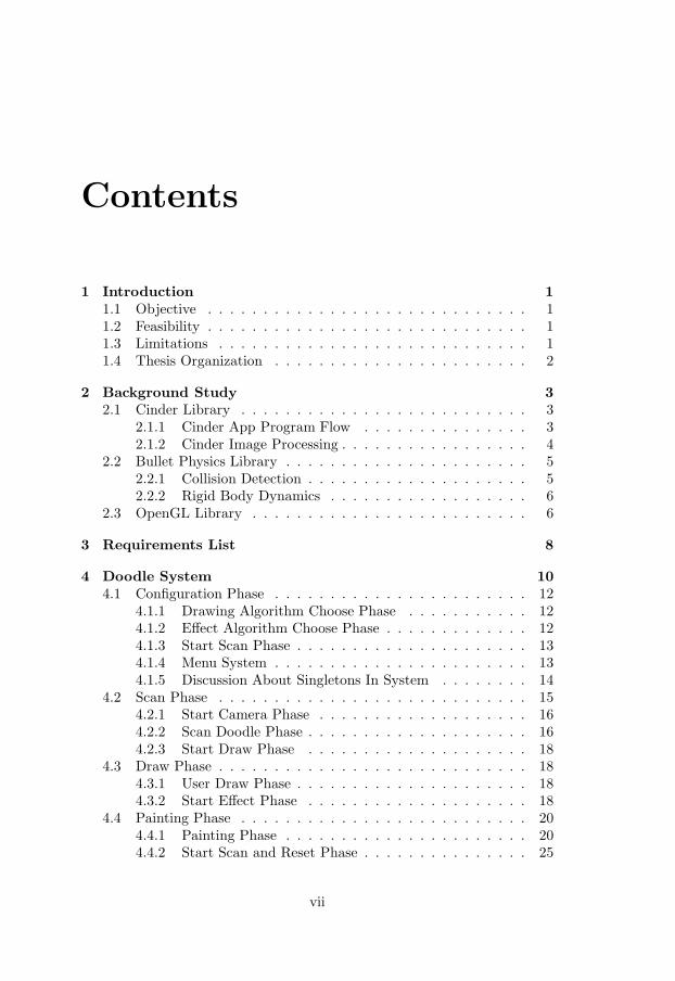
Contents
1 Introduction 1
1.1 Objective . . . . . . . . . . . . . . . . . . . . . . . . . . . . . 11.2 Feasibility . . . . . . . . . . . . . . . . . . . . . . . . . . . . . 11.3 Limitations . . . . . . . . . . . . . . . . . . . . . . . . . . . . 11.4 Thesis Organization . . . . . . . . . . . . . . . . . . . . . . . 2
2 Background Study 3
2.1 Cinder Library . . . . . . . . . . . . . . . . . . . . . . . . . . 32.1.1 Cinder App Program Flow . . . . . . . . . . . . . . . 32.1.2 Cinder Image Processing . . . . . . . . . . . . . . . . . 4
2.2 Bullet Physics Library . . . . . . . . . . . . . . . . . . . . . . 52.2.1 Collision Detection . . . . . . . . . . . . . . . . . . . . 52.2.2 Rigid Body Dynamics . . . . . . . . . . . . . . . . . . 6
2.3 OpenGL Library . . . . . . . . . . . . . . . . . . . . . . . . . 6
3 Requirements List 8
4 Doodle System 10
4.1 Configuration Phase . . . . . . . . . . . . . . . . . . . . . . . 124.1.1 Drawing Algorithm Choose Phase . . . . . . . . . . . 124.1.2 Effect Algorithm Choose Phase . . . . . . . . . . . . . 124.1.3 Start Scan Phase . . . . . . . . . . . . . . . . . . . . . 134.1.4 Menu System . . . . . . . . . . . . . . . . . . . . . . . 134.1.5 Discussion About Singletons In System . . . . . . . . 14
4.2 Scan Phase . . . . . . . . . . . . . . . . . . . . . . . . . . . . 154.2.1 Start Camera Phase . . . . . . . . . . . . . . . . . . . 164.2.2 Scan Doodle Phase . . . . . . . . . . . . . . . . . . . . 164.2.3 Start Draw Phase . . . . . . . . . . . . . . . . . . . . 18
4.3 Draw Phase . . . . . . . . . . . . . . . . . . . . . . . . . . . . 184.3.1 User Draw Phase . . . . . . . . . . . . . . . . . . . . . 184.3.2 Start Effect Phase . . . . . . . . . . . . . . . . . . . . 18
4.4 Painting Phase . . . . . . . . . . . . . . . . . . . . . . . . . . 204.4.1 Painting Phase . . . . . . . . . . . . . . . . . . . . . . 204.4.2 Start Scan and Reset Phase . . . . . . . . . . . . . . . 25
vii

CONTENTS CONTENTS
4.5 Performance . . . . . . . . . . . . . . . . . . . . . . . . . . . . 25
5 Further Development 30
5.1 Further Development About Drawing Algorithm Modules . . 305.2 Further Development About Scan Multiple Doodles . . . . . 315.3 Further Development About Effect Algorithm Module . . . . 31
5.3.1 EI’Beem Fluid Library . . . . . . . . . . . . . . . . . . 315.3.2 MSAFluid Library . . . . . . . . . . . . . . . . . . . . 325.3.3 Bullet SPH Fluid . . . . . . . . . . . . . . . . . . . . . 32
5.4 Further Development About Color Mode . . . . . . . . . . . . 32
6 Conclusions 34
viii

Chapter 1
Introduction
1.1 Objective
The objective of this thesis is to build a doodle system to perform that theuser can scan a hand drawn doodle on white paper in natural light into thesystem, draw the doodle in different ways in the system and apply differenteffects on the doodle. The doodle affected by the effect will eventually fallonto a canvas in the system to result in a painting. During this processmentioned above, the user can take pictures by pressing specific keys onkeyboard. The specific requirements are presented in Chapter 3.
1.2 Feasibility
As more and more graphic related requirements are needed to be fulfillednowadays, a plenty of commercial or open source graphic engines such asOGRE, Cinder become available. Easy-to-use and powerful APIs’ providedby those graphic engines guarantee the graphic part implementation of thedoodle system.
Like graphic engines, more and more physics engines such as Bullet,Open Dynamics Engine come out because of growing needs of physics sim-ulations. APIs’ provided by those physics engines support the physics partimplementation of the doodle system. In addition, integration between twodifferent engines is not a new subject. In some area, for example, gamedevelopment area, graphic engine and physics engine are always integratedto be a part of game engine.
1.3 Limitations
Since this project is merely the first version, only basic modules are imple-mented. This thesis mainly focus on this first version and only the modules
1

1.4. THESIS ORGANIZATION CHAPTER 1. INTRODUCTION
that have been implemented are included in this thesis. But the architectureof the project, relationships among modules and the structure of modulesleave a extendable space for further development.
1.4 Thesis Organization
The rest of the thesis is organized as follows. Background study is presentedin Chapter 2. Requirement list is presented in Chapter 3. In chapter 4 theimplementation of thesis project is presented. The future developments arediscussed in Chapter 5. The conclusions are presented in Chapter 6.
2
Chapter 2
Background Study
This project is developed on top of Cinder framework and Bullet Physicslibrary. Cinder and Bullet is not the only combination. We choose Cinderand Bullet is because that they are open source libraries and they are rel-atively well maintained among open source libraries. In addition, Cinderprovides a very clear, easy to use framework and supports direct OpenGLcode.
2.1 Cinder Library
Cinder is a free, open source C++ library which provides a lot of functionsand classes for programmers to fast create coding in graphics, audio, video,networking, image processing and computational geometry. In addition,Cinder is a cross-platform library which means the same code works underdifferent platforms such as Mac OS, Windows, iPhone and iPad. Cinderis developed at The Barbarian Group as an internal project at the begin-ning. But now it is maintained and further developed by a community ofprogrammers and artists. Lots of efforts is put on Cinder to make it famil-iar and intuitive to C++ programmers by developing on top of idioms andtechniques used commonly by the C++ community.
2.1.1 Cinder App Program Flow
Cinder provides a very clear and easy to understand program flow for pro-grammers. The program flow is presented in Fig. 2. 1. PrepareSettings andsetup modules are used for parameters initialization. The loop among eventhandlers, update and draw modules represents that these three modulesare executed during each frame. Event handlers module is responsible forprocessing events triggered by users. Mouse events including mouse down,mouse up, mouse move, mouse drag, mouse wheel and key events such as keyup, key down are provided by Cinder library. Update module is designed for
3

2.1. CINDER LIBRARY CHAPTER 2. BACKGROUND STUDY
programmers to add new positions, color values, radius values etc of 2D im-ages or 3D models. Draw module is the place for programmers to use drawfunctions which are available in Cinder to draw different images 2D or 3D.The last shutdown module is used to quit program according to shut downevent triggered by users. In order to build a project, programmers need tofill codes in each module of the flow. This program flow is also adopted byour thesis project.
Figure 2.1: Cinder Program Flow
2.1.2 Cinder Image Processing
Cinder is well known for providing strong 2D and 3D graphics capabilities.A lot of drawing methods are available in Cinder for programmers to use.Those drawing methods support not only drawing 2D images such as cir-cle, rectangle, line, vector, 2D texture etc, but also drawing 3D models tothe screen. Since OpenGL is integrated into Cinder, the drawing methodsmentioned above are basically implemented by wrapping OpenGL codes in-side. Except that, full-featured classes for OpenGL textures, FOBs, GLSL,
4

2.2. BULLET PHYSICS LIBRARYCHAPTER 2. BACKGROUND STUDY
VBOs, lights, materials and display lists are available in Cinder as well. Itis very convenient for programmers who are not familiar with OpenGL pro-gramming to have a quick start. Because drawing methods in Cinder fulfillalmost all requirements needed for making a graphic related project. It isalso very convenient for those programmers who are good at OpenGL pro-gramming to customize their own drawing methods by wrapping OpenGLcodes.
2D images on the filesystem can be drawn to the screen through Cinder.Image process in Cinder is presented in Fig. 2. 2. A surface which lives onCPU is created from the result of loadImage(). And then a texture whichlives on GPU is created from the surface or directly from loading image onthe filesystem. The image is drawn to the screen finally by using drawingmethods with texture as a argument. Surface, texture mentioned aboveare classes provided Cinder for manipulations such as filtering, replacingsections of bitmaps, or tweaking values of pixels.
Figure 2.2: Image Process In Cinder
TriMesh and VBOMesh are two mesh types in Cinder for rendering 3Dmodels. The creation of TriMesh and VBOMesh needs vertex informa-tion, color information, texture coordinate information. But unlike TriMesh,VBOMesh stores all vertex data on the graphic card and allows program-mers to modify the data on the graphic card without downloading all ofit. In order to create a mesh in a quick way, Objloader class is brought into create a TriMesh or VBOMesh from loading a OBJ format file on thefilesystem.
2.2 Bullet Physics Library
Bullet Physics is open source physics library which provides 3D collision,soft body and rigid body simulations and published under the zlib license.
2.2.1 Collision Detection
Collision detection in Bullet is performed by a collision dispatcher iteratingover each pair of collision objects and applying different collision algorithmscorresponding to different types of collision objects involved to computecontact points.
5
2.3. OPENGL LIBRARY CHAPTER 2. BACKGROUND STUDY
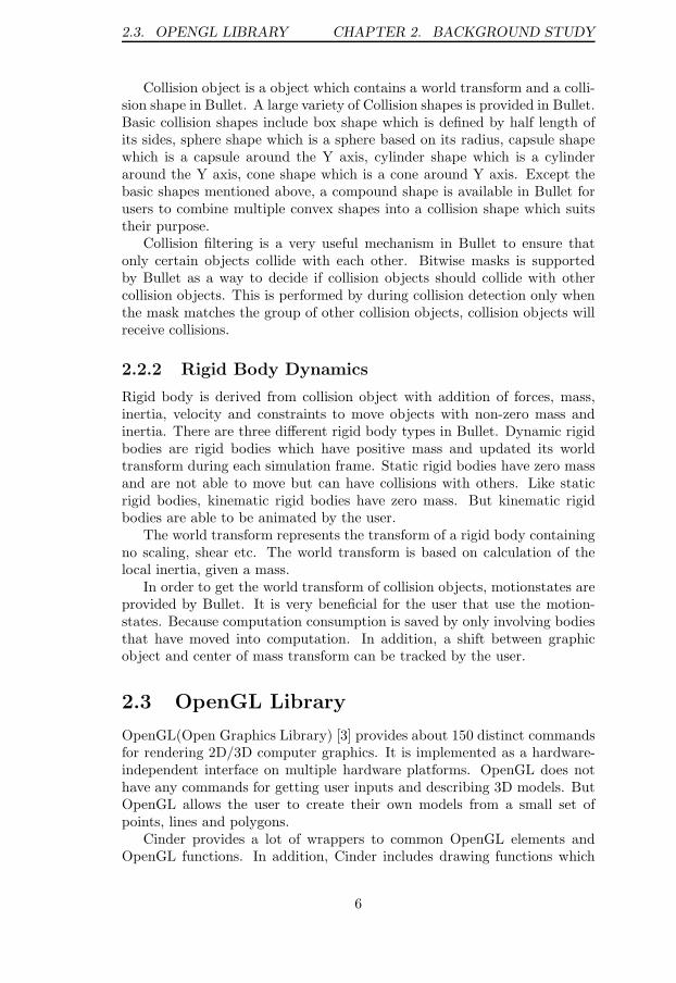
Collision object is a object which contains a world transform and a colli-sion shape in Bullet. A large variety of Collision shapes is provided in Bullet.Basic collision shapes include box shape which is defined by half length ofits sides, sphere shape which is a sphere based on its radius, capsule shapewhich is a capsule around the Y axis, cylinder shape which is a cylinderaround the Y axis, cone shape which is a cone around Y axis. Except thebasic shapes mentioned above, a compound shape is available in Bullet forusers to combine multiple convex shapes into a collision shape which suitstheir purpose.
Collision filtering is a very useful mechanism in Bullet to ensure thatonly certain objects collide with each other. Bitwise masks is supportedby Bullet as a way to decide if collision objects should collide with othercollision objects. This is performed by during collision detection only whenthe mask matches the group of other collision objects, collision objects willreceive collisions.
2.2.2 Rigid Body Dynamics
Rigid body is derived from collision object with addition of forces, mass,inertia, velocity and constraints to move objects with non-zero mass andinertia. There are three different rigid body types in Bullet. Dynamic rigidbodies are rigid bodies which have positive mass and updated its worldtransform during each simulation frame. Static rigid bodies have zero massand are not able to move but can have collisions with others. Like staticrigid bodies, kinematic rigid bodies have zero mass. But kinematic rigidbodies are able to be animated by the user.
The world transform represents the transform of a rigid body containingno scaling, shear etc. The world transform is based on calculation of thelocal inertia, given a mass.
In order to get the world transform of collision objects, motionstates areprovided by Bullet. It is very beneficial for the user that use the motion-states. Because computation consumption is saved by only involving bodiesthat have moved into computation. In addition, a shift between graphicobject and center of mass transform can be tracked by the user.
2.3 OpenGL Library
OpenGL(Open Graphics Library) [3] provides about 150 distinct commandsfor rendering 2D/3D computer graphics. It is implemented as a hardware-independent interface on multiple hardware platforms. OpenGL does nothave any commands for getting user inputs and describing 3D models. ButOpenGL allows the user to create their own models from a small set ofpoints, lines and polygons.
Cinder provides a lot of wrappers to common OpenGL elements andOpenGL functions. In addition, Cinder includes drawing functions which
6
2.3. OPENGL LIBRARY CHAPTER 2. BACKGROUND STUDY
are implemented by wrapping OpenGL codes in. This is very convenient forthe user to have a quick start with graphic programming. An abstractionlayer is built by Cinder between the user and OpenGL. For users who aregood at OpenGL or want to build up their own models for rendering, it isallowed to directly program with OpenGL code.
7

Chapter 3
Requirements List
In order to implement the doodle system described in Chapter 1, a plenty offunctions need to be listed and implemented individually. In this Chapter,we split the doodle system into a long requirements list to be fulfilled. Aslong as all requirements on the list are achieved, the doodle system will becreated. The requirements list is listed as follows:
1. Hand drawn doodles on white paper in natural light can be scannedinto the system by camera.
2. Doodles in the system are stored as a group of particles.
3. The user can draw scanned doodles on the screen by dragging mouse.
4. Multiple doodle drawing ways such as single and massive can be im-plemented.
5. Multiple effects such as physics effect can apply on doodles.
6. Multiple painting effects can be implemented such as oil painting, wa-ter color, 3D painting, sand simulation, fluid simulation etc.
7. The user can choose which doodle drawing way to apply.
8. The user can customize the chosen doodle drawing way by setting upcorresponding parameters.
9. The user can choose which effect and painting effect to apply.
10. The user can customize the chose effect and painting effect by settingup corresponding parameters.
11. The user can observe the whole painting generation process from thescreen.
8

CHAPTER 3. REQUIREMENTS LIST
12. The user can take picture during the painting generation process bypressing keyboard.
13. The user can choose to scan another doodle or set up parameters againwithout restarting the program after painting generated.
14. The doodle system can be installed on multiple platforms such asWindows, Mac, Ipad, Android etc.
In the end, requirements which are implemented are just a part of listabove. Oil painting effect and 3D painting effect have performance problems,a further optimization will be in need. Fluid effect is not implemented, canbe added to to-do list. Drawing massive doodles are not done. The doodlesystem can be installed only on Windows platform only.
9

Chapter 4
Doodle System
The doodle system consists of four subsystems which are module switchingsystem, parameter module system, particle system and menu system. Mod-ule switching system is responsible for loading different modules accordingto different phases. Modules in the doodle system can be divided into config-uration module, scan module, drawing algorithm modules, effect algorithmmodules and other functional modules. Each module has at most one param-eter module which stores all the parameters needed by the module. Similarto module switching system, parameter module system’s functionality is toload parameter modules for the user to set up the parameters in order tohave a user desired performance. Particle system in the doodle system is incharge of creation, deletion, update, draw and a series of manipulations onparticleObjs which is the data structure for scanned doodle and particles.Particles are the basic element of a particleObj. Like particle system, menusystem supports creation, deletion, update, draw and a set of operations onmenus and options in the system.
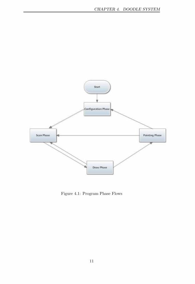
The program is always in one of four phases which are configurationphase, scan phase, draw phase and painting phase. The relations amongphases is presented in Fig.4.1. When the doodle system starts running, itenters the configuration phase firstly, then switches to the scan phase, thedraw phase and the painting phase. During the draw phase, the user canstep back to the scan phase to scan a more satisfied doodle. During thepainting phase, the user can choose to go to scan phase to scan anotherdoodle or go back to the configuration phase to set up parameters and thenrestart.
The first phase is outlined in 4.1, the second phase is outlined in 4.2,the third phase is outlined in 4.3, the forth phase is outlined in 4.4 and theperformance is outlined in 4.5.
10
CHAPTER 4. DOODLE SYSTEM
Figure 4.1: Program Phase Flows
11

4.1. CONFIGURATION PHASE CHAPTER 4. DOODLE SYSTEM
4.1 Configuration Phase
In this phase, a configuration module is loaded. This module is responsiblefor the user choosing drawing algorithms, effect algorithms and setting upcorresponding parameters. Three child phases are split in configurationphase.
The first phase is outlined in 4.1.1, the second phase is outlined in 4.1.2,and the third phase is outlined in 4.1.3.
4.1.1 Drawing Algorithm Choose Phase
This phase is performed by the user choosing one drawing algorithm from adrawing algorithm selection menu on the screen. In what way the scanneddoodle is drawn on the screen is determined by which drawing algorithmis chosen. Drawing algorithm here is a module type in the system. Onlyone drawing algorithm module is available in the current version. Thismodule supports drawing a single doodle which is comprised of particles onthe screen by the user dragging mouse in the draw phase. More drawingalgorithm modules are able to be added into the system for the user choosingin the further development. More details can be found in Chapter 5.
After choosing the drawing algorithm module, a corresponding param-eter module is activated for the user to set up parameters needed by thedrawing algorithm module. Parameters are kept in the parameter moduleand used in the scan phase to create a user customized doodle. The pa-rameter module mentioned above contains parameters such as properties ofparticle :particle radius, particle color, particle life span etc, properties ofparticle dip which is generated by a particle impacting onto the canvas inthe system:dip resolution etc and color mode which represents color effectin the painting phase:default, oil painting and mesh.
This phase is implemented by that the configuration module sets thedrawing flag via using an interface of drawing algorithm selection menuto draw the menu on the screen at the beginning. After the user choosethe drawing algorithm, the parameter module contained in the option isactivated and draws itself on the screen. Meanwhile, a drawing parameterconfirm menu draws itself on the screen by the configuration module settingits drawing flag. When the parameter setting is done, the user click theconfirm option in the drawing parameter confirm menu. The configurationmodule detects that the drawing flag of the drawing parameter confirm menuis false and sets the drawing flag of the effect algorithm selection menu totrue to draw the menu on the screen. More details about option and menucan be found in Section 4.1.4.
4.1.2 Effect Algorithm Choose Phase
In this phase, an effect algorithm module is chosen from an effect algorithmselection menu by the user. What kind of effect which apply on the doodle
12

4.1. CONFIGURATION PHASE CHAPTER 4. DOODLE SYSTEM
in the painting phase is decided by the chosen effect algorithm module.Only one physics effect algorithm module is offered in the current system.Collisions among particles and directional forces such as gravity are addedon the doodle by this module. The effect algorithm selection menu is alsoextendable in the further development for the user to have more choices.
A corresponding parameter module is activated like in the drawing al-gorithm choose phase after the user choosing the effect algorithm module.A list of parameters such as gravity, anti-gravity, left force, right force andfalling height is available for the user to set up. Parameters are kept in themodule for the configuration in the painting phase.
In this phase, after the user choose the physics effect algorithm, theparameter module contained in the option is activated and draws itself onthe screen. Meanwhile, a effect parameter confirm menu draws itself onthe screen by the configuration module setting its drawing flag. When theparameter setting is done, the user click the confirm option in the effect pa-rameter confirm menu. The configuration module detects that the drawingflag of the effect parameter confirm menu is false and sets the drawing flagof the start scan selection menu to true to draw the menu on the screen.
4.1.3 Start Scan Phase
This phase is performed by the user clicking a start scan option from the startscan selection menu. After clicking, the configuration module is ended andthe scan module contained in the option is loaded in the module switchingsystem. The doodle system enters the scan phase.
4.1.4 Menu System
The menu system in the doodle system consists of a menu controller module,multiple selection menus and multiple options. Menu controller is a modulewhere all the selection menus in the system update and draw themselves. Inaddition, menu controller provides interface for creating selection menu onthe run time. This is implemented by having a menu vector which stores allthe menus in the doodle system in the menu controller. When new menusare created, they are pushed into the menu vector. During each frame, themenu vector iterates through every menus in the vector to update and drawthose menus. The interface mentioned above which can create a selectionmenu on the run time supports further development of the doodle system.More detail is discussed in Chapter 5.
In order for the further development to customize menus, an abstractmenu class is provided in the doodle system. Like menu controller, menuclass contains a map which is used for all options of a menu to update anddraw themselves. The first value in the map represents option which belongsto a menu, the second value in the map stores a menu which is a sub menuand can be drawn when mouse hovering on the option. The sub menu isnot used in the current version, but it can be used in further development.
13
4.1. CONFIGURATION PHASE CHAPTER 4. DOODLE SYSTEM
Different menus according to the specific requirements are able to be createdby inheriting from the abstract menu.
There is only selection menu inherited from the abstract menu class inthe current system. All the menus used in the system are selection menu ob-jects. Except the functionality from abstract menu, selection menu providesinterfaces corresponding to mouse events such as menu stopping drawingitself when a mouse clicking event on the selection menu occurs. Selectionmenu also provides interfaces for creating options and linking its related submenu and interfaces for setting drawing flag and drawing position.
There are eight selection menus through whole system. Drawing algo-rithm selection menu contains a list of drawing options containing drawingalgorithm modules which the user can choose to draw different doodles inthe draw phase. Drawing parameter confirm menu only includes one op-tion which is for the user to switch to effect algorithm selection menu. Likedrawing algorithm selection menu, the user can select different effect algo-rithm modules to perform different effects on the doodle. Effect parameterconfirm menu which also is comprised of one option switches to start scanmenu by the user clicking. Start scan menu is used to load the scan mod-ule and end the configuration module. Start draw selection menu which islocated in the scan phase also uses module switching system to enter thedraw phase. Start effect selection menu and reset selection menu, like startdraw selection menu above, are used to enter the painting phase and theconfiguration phase.
Options are basic elements in a menu. An option object contains at mostone module reference and parameter module reference. There are three dif-ferent types of options in the system. The first option type detects if theoption is clicked and uses a change module interface from module switchingsystem to load the module stored in the option. The second option type isused to pass the drawing algorithm module in the option to the start drawselection menu and use a change parameter module interface from parametermodule system to load the parameter module in the option if there is one.Similar to the second type, the third option type passes the effect algorithmmodule contained in the option to the start effect selection menu and loadits corresponding parameter module if it is null in the option. These threetypes mentioned above perform their functionality under different masks. Inaddition, option provides interfaces corresponding mouse events and inter-faces for updating and drawing themselves. Option class also has interfacefor customizing according to different requirements such as different colors,different shapes, different width and height, different level of transparencyetc.
4.1.5 Discussion About Singletons In System
Considering menu controller is needed across the system, menu controlleris programmed according to Singleton pattern [4]. This is performed by
14

4.2. SCAN PHASE CHAPTER 4. DOODLE SYSTEM
that only one object from instantiation of menu controller class through thewhole system. Since menu controller keeps track of all menus in the doodlesystem, apparently it is not a good idea that menu controller is initializedto a new object every time it is needed.
The module switching system contains a module controller and multiplemodules in the system. Module controller is responsible for loading modulesand keeping track of the current running module. This is implemented bythat there is a module vector in the module controller. When the modulecontroller is loading a module, the old module on the top of the vector ispopped out and new module is pushed into the vector. Module controlleralso provides an interface of loading modules for other components in thesystem. Since module controller is used in different options to load differentmodules in the system wide, it is more efficient if only one object of it exists.
Similar to the module switching system, the parameter module systemconsists of a parameter module controller and multiple parameter modules.The parameter module controller has the same functionality as the modulecontroller except that modules are replaced by parameter modules whichstore all parameters needed by modules. For the same reason, the parametermodule controller is also programmed to a singleton.
Configuration module, scan module, drawing algorithm modules, effectalgorithm modules and other modules which will be introduced in latersections all inherit from a same abstract class named Algorithm. Consideringmodules will be loaded in the module controller multiple times, membervariables of some modules are responsible for keeping track and membervariables of some modules are needed in other components across the system,all modules are programmed as singletons. However, multiple instances fromone module could be required in further development, maybe it is not a goodidea to program all modules to singletons. Besides, too many global statesin the system can result in difficulty of unit testing increasing and slowdown performance because of multiple components fighting for the access tosingleton. Only modules which act as service providers to other componentsare programmed to singleton can be an alternative.
Because of similar reasons, all parameter modules are made as single-tons. Parameter modules act as data warehouse in the system. In thefurther development, synchronized blocks might be needed, singletons ob-viously will cause the system slowing down. Referring to the alternativementioned above, it can be an idea to just make specific parameter modulesas singletons.
4.2 Scan Phase
In scan phase, a hand drawn doodle on white paper is scanned into thesystem in natural light, and a doodle comprised of particles is created ac-cording to parameters of the chosen drawing algorithm module. There arethree child phases in scan phase.
15
4.2. SCAN PHASE CHAPTER 4. DOODLE SYSTEM
The first phase is outlined in 4.2.1, the second phase is outlined in 4.2.2and the third phase is outlined in 4.2.3.
4.2.1 Start Camera Phase
In this phase, camera devices in the user’s computer are initialized andduring each frame latest captures taken by camera devices are rendered onthe screen. This is supported by a capture vector and a texture vector inthe scan module.
Capture is a class in Cinder Library. It is used for obtaining all devicesconnected to the user computer system and manipulating those devices tocapture video or return surfaces etc. Texture is a class in Cinder Library.It represents an image on the computer’s graphics card. As contrastedwith texture, surface mentioned above is also a class in Cinder Library andrepresents an image located on the computer’s CPU.
When enters the scan phase, all devices connected to the user computerare listed out by using ci::Capture::getDevices()from Capture class and thenare pushed into a device vector. The vector iterates through all elementsand during each iteration one Capture object is created according to deviceand defined capture area and pushed into the capture vector. All Captureobjects start capturing when they are pushed into the capture vector.
During each frame, latest surfaces returned by capture objects in thecapture vector are transformed to corresponding texture objects and thenpushed into the texture vector. Texture vector iterates through all texturesin the texture vector and render those textures on the screen by using drawtexture function from Cinder.
4.2.2 Scan Doodle Phase
This phase is performed by the user pressing a key on keyboard to scan ahand drawn doodle from camera. And a doodle which consists of multipleparticles is created and stored in the particle system.
Except interfaces for updating and drawing, the scan module providesinterface for scanning doodles. This interface responds to key events. Whenthe user presses a certain key from the keyboard, a surface is captured and achannel object is created from this surface. Channel here is a class in Cinder.It represents an image in it’s own right - one for the red, the green, the blueand sometimes alpha [5]. An grayscale channel is used in the system.
When the channel creation ends, a particleObj object is created by par-ticle controller. Particle related parameters are assigned to the new cre-ated particleObj object for generating desired particles. Particle dip relatedparameters are also passed to the particleObj object for creating user cus-tomized painting. And then according color mode the user chosen, a differentthresh value which controls maximum particles will be in the particleObj isinitialized. Other parameters such as connectionDensity which determinesdistance among particles are used in scan algorithm.
16

4.2. SCAN PHASE CHAPTER 4. DOODLE SYSTEM
Scan algorithm is a process of creating a doodle in the system from a handdrawn doodle. Scan starts by iterating through each pixel in the channel.The scan algorithm is presented in Fig 4.2. A central particle is createdwhen the first pixel which fulfills the condition in the channel is met. Thecentral particle is the central of a group of particles which form a particleObjobject. All other particles which are created after central particle keep arelative distance to the central one. This mechanism is designed for thedraw phase in which the user draws doodle by dragging mouse. A currentmouse position is assigned to the central particle and all other particlesinside particleObj object compute their own positions by adding relativedistance with the position of central particle. As Fig.4.2 shows, two threshvalues are imported into the scan algorithm. Thresh is a value for limitingthe number of particles can be generated. This is designed for balancingbetween system performance and painting effect. The other thresh valueis ConnectionDensity. It is used for arranging the density among particles.During the scan process, a maximum distance is obtained from computingevery particle distance to the central particle. This maximum distance isneeded by the particleObj object assigning slight varying colors to particlesunder default color mode.
Multiple particles, multiple particleObjs and a particle controller com-prise the particle system. Particle controller keeps track of all particleObjobjects by iterating through all elements in particleObj vector and providesinterfaces for creating, updating and drawing particleObj objects. Besides,particle controller has interface for responding to mouse events such as mov-ing a particleObj object by the user dragging mouse. Considering particlecontroller is used across whole system, it is designed as a singleton.
ParticleObj represents a doodle inside the doodle system. It managesparticles which comprise the doodle and particle dips which form a painting.So there are two vectors in the particleObj. One is for keeping track ofparticles and the other one is for particle dips. In addition, particleObjprovides interfaces for creating, updating, drawing particles and particledips and interface for assigning varying colors similar to the color the userchose to particles in order to result in a better painting under default colormode and oil painting color mode. According to different color modes,corresponding blocks in particleObj are executed during the run time. Moredetails about color mode can be found in Section 4.4.
Considering further extension, particleObj class has a name and id num-ber which are designed for allowing the user scan and draw several doodleson the screen. Although it is not available in current version, it provides asupport for further development. More details about further developmentis discussed in Chapter 5.
Particle class represents a basic element in the particle system. Particleprovides interfaces for updating, drawing itself. Particle and particle dipmentioned above are instances of same class but under different type masks.Particle type masks is designed for managing different particle instances
17

4.3. DRAW PHASE CHAPTER 4. DOODLE SYSTEM
in a easier way. There are four particle type masks in the current version.Sphere mask represents a sphere particle which is in XYZ coordinate system.Texture mask represents a circle particle on the XY plane. Mesh mask bringsa 3D model particle with texture and shader. Dip mask determines a circleparticle on the XZ plane. Particle type masks are determined by the colormode in the particleObj.
4.2.3 Start Draw Phase
This phase is performed by the user clicking a start draw option on startdraw selection menu. After clicking the option, the scan phase is ended andthe chosen draw algorithm module is loaded in the system.
There is a safe mechanism which is applied in the scan module. Onlywhen a particleObj object is created from scanning, the start draw selectionmenu is drawn on the screen. This is considered because that in differentlight conditions, scans have possibilities to fail.
4.3 Draw Phase
In draw phase, the chosen drawing algorithm is applied and the user drawsdoodle by dragging mouse. Given the circumstance that only one drawingalgorithm module is available in the current version, the user can only drawa single doodle in this phase. There are two child phases in draw phase.
The first phase is outlined in 4.3.1 and the second phase is outlined in4.3.2.
4.3.1 User Draw Phase
In this phase, the chosen drawing algorithm has already loaded and the userdraws a doodle by dragging mouse.
This is implemented by that when the user is dragging mouse, an in-terface for moving particleObj object in the particle controller is activated.This interface takes a current mouse position as argument and pass it to cen-tral particle in particleObj object. Then like we mentioned in 4.2 Section,all other particles in the particleObj object compute their own positions byadding central particle position with relative distance. After all these stepsabove, a doodle is drawn on the place where the user drags the mouse.
4.3.2 Start Effect Phase
This phase is performed by the user clicking a start effect option on starteffect selection menu. After clicking the option, the draw phase is endedand the chosen effect algorithm module is loaded in the system.
18

4.3. DRAW PHASE CHAPTER 4. DOODLE SYSTEM
Figure 4.2: Scan Algorithm
19

4.4. PAINTING PHASE CHAPTER 4. DOODLE SYSTEM
4.4 Painting Phase
In painting phase, the chosen effect algorithm module which is physics effectalgorithm module in this thesis is loaded and particles start to move basedon forces applied on them. Then particles fall onto a canvas in the systemand a painting is generated form it. During the painting phase, the usercan take pictures via pressing a key on the keyboard. There are two childphases in effect phase.
The first phase is outlined in 4.4.1 and the second phase is outlined in4.4.2.
4.4.1 Painting Phase
Physics effect algorithmmodule is implemented by integrating Bullet physicsinto Cinder. In the set up phase of this module, a dynamic world is createdby using corresponding interfaces provided by the Bullet. Dynamic worldis an environment where bullet physics simulation happen. The force pa-rameters which are set up by the user and stored in the parameter moduleare passed into the dynamic world as the forces to apply on particles later.Then a canvas object which is used for painting generation and a trackingcamera object which is responsible for tracking the whole painting genera-tion process are created. The particleObj object which represents a doodlein the system is then copied and pushed into physics stack which is a parti-cleObj vector in the physics effect algorithm module. The mechanism hereis designed to allow the user choose different doodles or multiple doodles atthe same time to apply effects on. Although this mechanism is not used inthe current version, it provides a support for the further extension. Moredetails can be found in Chapter 5. After above steps are finished, rigidbodies are created based on particles’ and canvas’s radius, positions. Thoserigid bodies are necessary components in the dynamic world in order to per-form physics simulations. At the end of this set up phase, correspondingparameters which are used in two equations to compute splash radius whena particle hits on the canvas are initialized. The equations are presentedbelow.
We = ρ ∗ u20 ∗ d0/σ (4.1)
R = r0 + 0.12 ∗√We ∗ r0 (4.2)
There are some certain assumptions [6] when using these two equations.After the set up of the module is finished, simulation in the dynamic
world is initiated. During each frame, positions of every particles and can-vas are computed from simulation according to forces applied in dynamicworld and which collision masks are turned on. Those positions are thenassigned to corresponding particles and particles draw themselves based onnew positions. Collision masks mentioned above is a mask mechanism inBullet Physics designed to perform collision filtering. In order to have a ba-sic doodle shape after particles falling on the canvas, three collision masks
20

4.4. PAINTING PHASE CHAPTER 4. DOODLE SYSTEM
are provided in the physics effect algorithm module. When particles arein flight, collision mask which represents collisions among particles is off,only collision mask which represents collisions between particle and canvasis on. Until each particle hits on the canvas, collisions with other particlesis turned on. A splashing effect is resulted in from that.
When particles impact onto the canvas, particle dips are created at theplace particles hit. This is implemented by using a particle dip creationinterface from particleObj class. Dip radius is computed according to twoequations presented before. Another mechanism here is color mode whichis from the particleObj class. Different color modes decide not only whatparticle type will be used, but also what painting effect will be performed.There are three color modes available in the current version. Default colormode is the mode in which particle is drawn as a 3d sphere, particle color isadjusted similar to the color the user set up during configuration phase andparticle dip is drawn as a 2d circle on XZ plane. The painting in defaultcolor mode is presented in Fig.4.3. Oil painting color mode is the secondcolor mode in which particle is also drawn as a 3d sphere, particle dip isalso drawn as a 2d circle on XZ plane. But a module based on oil paintingalgorithm [7] is executed during each frame to compute dip colors to resultin oil painting effect. In order to achieve a clear oil painting effect, particlecolor is adjusted totally different to the color the user set up and each particledip is created as a circle which is comprised of many small circles. The ideabehind this is that considering a huge amount of computation is needed tocalculate pixel colors in order to have oil painting effect, we decide to usea pixel simulation way to reduce the computation complexity. The specificway is that we make each dip formed by a group of smaller circles, instead ofcalculating pixels in each dip, we calculate colors of smaller circles. But thisbrings another problem here. Since draw circle method in Cinder libraryneeds to pop matrix first and push back matrix after drawing, that meansmore circles are drawn more consumptions for popping and pushing areneeded. While only one pop and push back matrix is needed if calculatingpixels. In order to compare two solutions mentioned above, an analysis iscertainly acquired here to get a trade off of how many circles comprise adip. The painting in oil painting color mode is presented in Fig.4.4. Thelast color mode is 3D model color mode in which particle is drawn as a mesh,no color is needed and no particle dip is created when particle impacts ontocanvas. The painting in 3D model color mode is presented in Fig.4.5. AsFig.4.5 shows, a 3D diamond model is used under 3D model color mode. Italso supports other 3D models, for example when a sand model is used forparticles, then a sand painting can be simulated on the screen.
A taking picture module is activated during the painting phase. Thismodule is responsible for copying a window surface and saving as a pictureresponding to the user pressing key event.
21

4.4. PAINTING PHASE CHAPTER 4. DOODLE SYSTEM
Figure 4.3: Default color mode painting
22

4.4. PAINTING PHASE CHAPTER 4. DOODLE SYSTEM
Figure 4.4: Oil Painting Color Mode
23

4.4. PAINTING PHASE CHAPTER 4. DOODLE SYSTEM
Figure 4.5: 3D Model Color Mode
24

4.5. PERFORMANCE CHAPTER 4. DOODLE SYSTEM
4.4.2 Start Scan and Reset Phase
This phase is performed by the user clicking a start scan option on startscan selection menu or a reset option on reset selection menu. Two selectionmenus are provided here. So the user can choose to scan another doodlewithout setting up parameters again. If the user is not satisfied by theparameters set up before, user can choose to go to configuration phase tostart over.
4.5 Performance
In this section, we present the performance of the doodle system.The hardwares the doodle system runs upon are: Intel(R) Core(TM) i3
CPU M330 @2.13GHZ, ATI Radeon HD 5470 graphic card and 2GB RAMmemory. It is a old fashioned standard computer.
The performance is measured by FPS of the doodle system when differentnumber of particles exist in the painting phase. More specifically, there aretwo kinds of particles in the painting phase. One particle is a 3D sphereparticle which is a part of doodle in the system. And the other particle isa 2D circle particle which is created when a sphere particle impacts on thecanvas in the system. Since only sphere particles have collision calculationconsumption, circle particles have nothing but drawing consumption. Thestandard FPS in the doodle system is set to 30. That means frames will beupdated 30 times per second. If the sphere particles’ collision calculation,drawing and circle particles’ drawing can not be done before next frameupdating, next frame will be dropped. When FPS drops below 10, thepainting phase will look fragmented.
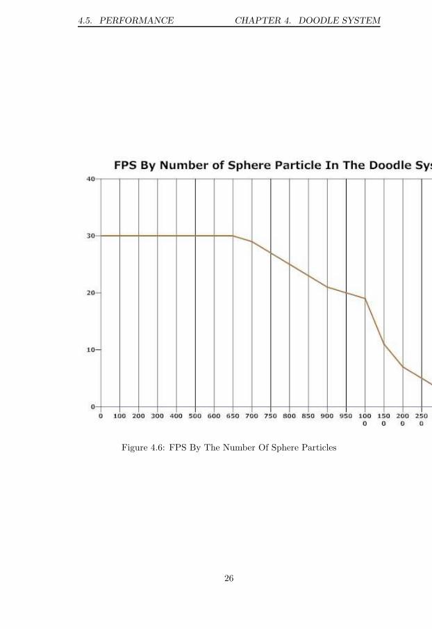
As the number of sphere particle increases, FPS drops down graduallyas Fig.4.6 shows. When sphere particle number is larger than 950, FPSdrops below 20. Although more available sphere particles are better, moreconsumption on collision detection and drawing will lead to low FPS. Andthe fact that massive circle particles which are related to painting qualitywill result in FPS dropping also should be put into consideration. So wechoose 950 as the maximum number of sphere particle allowed in the system.
When the consumption of sphere particles is certain, FPS of the doodlesystem drops down as the number of circle particle increasing. As Fig.4.7shows, when the number of circle particle is larger than 24665, FPS dropsbelow 10. If we set the maximum number of sphere particle to 950 and setthe maximum number of circle particle to 24665, FPS remains above 10, thepainting quality is also guaranteed as the result shows in Fig.4.8. and thewhole painting phase is fluent from the user perspective. The performanceis still acceptable.
It is the main reason leading to low performance that the Collision de-tection and drawing of particles consume too much time. Since collisiondetection is handled by Bullet, it is already optimized. In order to achieve
25
4.5. PERFORMANCE CHAPTER 4. DOODLE SYSTEM
Figure 4.6: FPS By The Number Of Sphere Particles
26

4.5. PERFORMANCE CHAPTER 4. DOODLE SYSTEM
Figure 4.7: FPS By The Number Of Circle Particles
27

4.5. PERFORMANCE CHAPTER 4. DOODLE SYSTEM
Figure 4.8: Painting Under Certian Number of Particles
28
4.5. PERFORMANCE CHAPTER 4. DOODLE SYSTEM
better performance, an optimization is needed for particle drawing. Asmentioned in last section, when draws a particle, the matrix is popped andpushed once. One idea for optimization is to make the matrix popped andpushed only once for drawing all particles in the painting phase. In thisway, consumption on particle drawing can be decreased, FPS will grow andmore particles can be allowed to create in the painting phase.
29

Chapter 5
Further Development
In this chapter, we present some thoughts about further development of thisproject.
5.1 Further Development About Drawing Al-
gorithm Modules
In the current version, there is only one drawing algorithm module is avail-able. A single doodle is drawn in the draw phase. More drawing algorithmmodules can be added into the system. One idea is a drawing algorithmmodule which allows drawing massive doodles by the user dragging mouse.When the user drags mouse on the screen, a sphere comprised of scanneddoodles or a random arranged group of doodles is drawn at the place mousestays. This is can be implemented by using name and id member variables inparticleObj class. During the scan phase, a particleObj object with a uniquename is created and it’s id is initialized as 0. When enters the draw phase,multiple doodles with the same name but different id numbers are createdin a certain organized group according to different algorithms. After thepainting module is loaded, particleObj objects which have the same nameare pushed into the gravity stack. A painting made by massive doodles canbe generated.
Adding more draw algorithm modules to the system is also supported bythe menu system. More drawing algorithm options can be added into draw-ing algorithm selection menu by using addoption interface from selectionmenu class. No matter what option in drawing algorithm selection menuis chosen by the user, the corresponding drawing algorithm module will bepassed to start draw selection menu and parameters will be passed into thescan phase.
30

5.2. FURTHER DEVELOPMENT ABOUT SCAN MULTIPLE
DOODLES CHAPTER 5. FURTHER DEVELOPMENT
5.2 Further Development About Scan Multi-
ple Doodles
Although multiple doodles can be scanned into the system, only the latestone is used in the draw phase. If multiple doodles are available, the usercan have more choices to decide which doodle to draw or what combina-tions of different doodles to draw. And this can lead to very interestingpainting result. One idea about how to implement this is presented here. Aaddmenu interface from menu controller class supports creating a selectionmenu during run time. This interface can be used in the scan phase. Whena new particleObj object is created, a selection menu with one option whichcontains the chosen drawing algorithm module and the doodle name. Op-tion class needs a bit modifications. Except loading new algorithm module,passing drawing algorithm module and passing effect algorithm module, afourth functionality which can change doodle name in drawing algorithmmodule to doodle name in option object can be added. At the same time, avector which stores all changed doodle names can be added in drawing al-gorithm module. When the user scan a new doodle, an option with doodlename is created and drawn on the screen. During the draw phase, the usercan choose to draw different doodles by clicking corresponding options. Thedoodle name in drawing algorithm module is changed after each clicking,old one is saved to the vector. The doodle name is then passed to particlecontroller as a argument for particle controller to decide which doodle todraw. When effect algorithm module is loaded, the vector which have alldrawn doodle names is passed to effect algorithm module in order to applyeffect on those doodles.
5.3 Further Development About Effect Algo-
rithm Module
During the development, we tried to add a fluid effect algorithm modulewhich can make particles perform accurate fluid simulations. But it didnot work well. Considering time limitation, we focus on integrating a open-source fluid library with the doodle system.
5.3.1 EI’Beem Fluid Library
The first candidate in our radar is an open-source free surface fluid librarycalled EI’Beem[8]. It is based on the lattice-Boltzmann method (LBM) andis able to make fluid simulations very efficiently and physically accurate.EI’Beem is released under the GPL, and also integrated in 3D applicationBlender. But after visiting EI’Beem’s home page, we find out that EI’Beemstops further developing somehow and latest released version is availableonly for Unix like systems.
31

5.4. FURTHER DEVELOPMENT ABOUT COLOR MODECHAPTER 5. FURTHER DEVELOPMENT
In order to integrate EI’Beem into the project which is on Windowsplatform, a lot of time is needed to make it available to Windows system ordesign a new fluid algorithm based on EI’Beem core. In the future devel-opment of the doodle system, it can be a possible way to implement fluidsimulation that make EI’Beem available for Windows system.
5.3.2 MSAFluid Library
MSAFluid[9] comes in our sights after EI’Beem. MSAFluid is an open-sourcelibrary and provides real-time fluid simulations which is based on Navier-Stokes equations. In addition, MSAFluid library is already integrated withCinder library and is able to be used as a block under Cinder. It is veryconvenient to use MSAFluid with Cinder. However, MSAFluid providesoperations on pixels only on XY-plane to implement real-time fluid simula-tions. And this does not match particle-based doodle system. Besides, fluidsimulations performed by MSAFluid is more smoke trend than liquid trend.
5.3.3 Bullet SPH Fluid
There is a Smoothed Particle Hydrodynamics (SPH) fluid preview examplein Bullet Physics library. It is particle based simulation which quite matchesthe particle based doodle system we are working on. But SPH fluid is notavailable in current Bullet version yet. It will be integrated into Bullet innear future. As we can imagine, it is a good choice to implement a fluideffect algorithm by using Bullet SPH fluid for the future development. Notto mention that integration complexity will be reduced by using SPH fluid,because SPH fluid will be a part of Bullet which has already integrated intothe project.
5.4 Further Development About Color Mode
As mentioned in last Chapter 5, except default color mode other two colormodes are in need of improvements. Huge amount of computations forparticle oil painting colors during each frame is the first issue. Althougha pixel simulation solution is applied, trade off between performance andnumber of small circles which simulate pixels is still unknown. For furtherdevelopment, an analysis is needed for comparison between computationconsumption of direct pixel calculation and computation consumption ofusing pixel simulation and needed for obtaining a trade off between computerperformance and number of small circles used in pixel simulation.
Low performance of 3D mesh rendering is the second issue. A limitedsmall number of 3D particles are allowed to be created when 3D color mode ischosen. Computer performance goes down as thresh number of 3D particlesincrease. In order to achieve a high performance with huge amount of 3Dparticles, a optimization is apparently required in further development. The
32

5.4. FURTHER DEVELOPMENT ABOUT COLOR MODECHAPTER 5. FURTHER DEVELOPMENT
problem can come from Cinder library itself. For example, Cinder does notsupport rendering 3D models in a massive way. The problem can also becaused by bad 3D particle creating and deleting policy.
33

Chapter 6
Conclusions
In this thesis, an extendable system which supports scanning a hand drawndoodle from the camera into the system and generating a painting by ap-plying physics effect on the doodle has been implemented on top of Cinderand Bullet Physics libraries. This system fulfilled a part of requirementslist. But there is still a part of requirements list remaining unimplemented.The system itself supports a further development by adding new modulesinto the existing system.
The performance of the doodle system on a standard computer is stillacceptable. The scanned doodle size, the fluency of the painting phaseand the quality of the painting are guaranteed. In order to achieve bet-ter performance, optimization for drawing particles is needed in the futuredevelopment.
34

Bibliography
[1] The Barbarian Group. Cinder library. http://libcinder.org/.
[2] Erwin Coumans. Bullet physics library. http://bulletphysics.org/
wordpress/.
[3] consortium Khronos Group. Opengl library. http://www.opengl.org/.
[4] Wikipedia. Singleton pattern. http://en.wikipedia.org/wiki/
Singleton_pattern.
[5] Joshua Noble. Images in cinder. Channel Section First Line.
[6] B.Bossa E.Villermaux. Drop fragmentation on impact. J.Fluid Mech,2011.
[7] Supercomputingblog. Oil painting algorithm. http://
supercomputingblog.com/graphics/oil-painting-algorithm/.
[8] Nils Thuerey. Ei’beem. http://elbeem.sourceforge.net/.
[9] Memo Akten. Msafluid library. http://www.memo.tv/msafluid/.
35

BIBLIOGRAPHY BIBLIOGRAPHY
36

Avdelning, Institution
Division, DepartmentDatum
Date
Sprak
Language
� Svenska/Swedish
� Engelska/English
�
Rapporttyp
Report category
� Licentiatavhandling
� Examensarbete
� C-uppsats
� D-uppsats
� Ovrig rapport
�
URL for elektronisk version
ISBN
ISRN
Serietitel och serienummer
Title of series, numberingISSN
Linkoping Studies in Science and Technology
Thesis No. LIU-IDA/LITH-EX-A–12/074–SE
Titel
Title
Forfattare
Author
Sammanfattning
Abstract
Nyckelord
Keywords
This Master Thesis proposes a implementation for a doodle system whichcan scan hand drawn paper doodles using camera into the system and obtaina painting based on doodles impacting on a canvas in the system. The doodleswhich are scanned into the system are applied physical effects such as collisionsand forces on. The implementation is supported by Cinder Library [1] andBullet Physics Library [2] .The Cinder used in this thesis is an open source C++ library developed by
The Barbarian Group. The doodle system uses multiple draw methods andthe framework provided by Cinder to build graphic components and a newsystem in a quick and efficient way.The Bullet Physics Library used in this thesis is a professional open source
library for physics simulations. The Bullet is integrated into the doodle systemas a component which perform physics simulations on doodles.
Computer Science,Dept. of Computer and Information Science581 83 Linkoping
2013-01-22
-
LiU-Tek-Lic–2013:2013
-
http://XXX
Doodle Processing System Using Cinder Graphics and Bullet Physics
Zhang Wen
××
Doodle system, Cinder, Bullet

På svenska
Detta dokument hålls tillgängligt på Internet – eller dess framtida ersättare –
under en längre tid från publiceringsdatum under förutsättning att inga extra-
ordinära omständigheter uppstår.
Tillgång till dokumentet innebär tillstånd för var och en att läsa, ladda ner,
skriva ut enstaka kopior för enskilt bruk och att använda det oförändrat för
ickekommersiell forskning och för undervisning. Överföring av upphovsrätten
vid en senare tidpunkt kan inte upphäva detta tillstånd. All annan användning av
dokumentet kräver upphovsmannens medgivande. För att garantera äktheten,
säkerheten och tillgängligheten finns det lösningar av teknisk och administrativ
art.
Upphovsmannens ideella rätt innefattar rätt att bli nämnd som upphovsman i
den omfattning som god sed kräver vid användning av dokumentet på ovan
beskrivna sätt samt skydd mot att dokumentet ändras eller presenteras i sådan
form eller i sådant sammanhang som är kränkande för upphovsmannens litterära
eller konstnärliga anseende eller egenart.
För ytterligare information om Linköping University Electronic Press se
förlagets hemsida http://www.ep.liu.se/
In English
The publishers will keep this document online on the Internet - or its possible
replacement - for a considerable time from the date of publication barring
exceptional circumstances.
The online availability of the document implies a permanent permission for
anyone to read, to download, to print out single copies for your own use and to
use it unchanged for any non-commercial research and educational purpose.
Subsequent transfers of copyright cannot revoke this permission. All other uses
of the document are conditional on the consent of the copyright owner. The
publisher has taken technical and administrative measures to assure authenticity,
security and accessibility.
According to intellectual property law the author has the right to be
mentioned when his/her work is accessed as described above and to be protected
against infringement.
For additional information about the Linköping University Electronic Press
and its procedures for publication and for assurance of document integrity,
please refer to its WWW home page: http://www.ep.liu.se/
© [Zhang Wen]