Donna Ana Community College Project · Web viewReinforced Tilt-up Walls…………………..13...
25
Dona Ana Community College Project Senior Design I Group El Paso, Texas Group Members: Jose Nuñez Miguel Torres Eric Navarro Angel Morales Luis Elias Project Mentors: Ruben Ponce Angel Jimenez Special Thanks: Hong-Sioe Oey PhD P.E. Tuesday May 4, 2009 Submitted to: Professor John Walton P.E. PhD University of Texas at El Paso
-
Upload
phungtuyen -
Category
Documents
-
view
213 -
download
0
Transcript of Donna Ana Community College Project · Web viewReinforced Tilt-up Walls…………………..13...
Dona Ana Community College Project
Senior Design I Group
El Paso, Texas
Group Members:
Jose Nuñez
Miguel Torres
Eric Navarro
Angel Morales
Luis Elias
Project Mentors:
Ruben Ponce
Angel Jimenez
Special Thanks:
Hong-Sioe Oey PhD P.E.
Tuesday May 4, 2009
Submitted to:
Professor John Walton P.E. PhD
University of Texas at El Paso
El Paso, Texas

Table of Contents
Table of Contents………………………… i
Abstract………………………………….. ii
List of Figures…………………………….. iii
Introduction…………………………….….7
Structural Analysis……………………….. 9
Reinforced Tilt-up Walls…………………..13
Beams……………………………………… 13
Columns….……………………………….. 11
Steel Joists………………………………….13
Interior Partitions………………………….16

Dona Ana Community College
Abstract:
The Dona Ana Community College student alumni grow tremendously each year. For this reason, our group decided to contribute with the design of a new building for the growing number of college students. The main purpose of this project is to accommodate the new faculty and staff that will be attending this campus on the upcoming semesters. This new addition to the existent campus will consist of 6,750 square feet distributed into a one floor building consisting of one computer lab, two study rooms, one lobby, and one restroom area. The main components of the building structure include concrete tilt-up walls, beams, columns, and steel joists. All concrete members will be design with a concrete strength of 4,000 psi. The steel joist will have an allowable tensile strength of 30 ksi.

List of Figures
Figure 1
Beam distributed load and As…………………………10
Figure 2
Side view of beam dimensions and As ……...................10
Figure 3
Column Dimensions and As ……………………………13
Figure 4
Concrete Tilt-up Wall at Lifting Operation……………14
Figure 5
Concrete Tilt-up Analysis Procedure………………….15
Figure 6
Shear and Moment Diagram for Tilt-Up Wall………...16
Figure 7
The dimensions of the site ……………………………..17

List of Tables
Table 1
Dead loads and Live loads …………………….. 7
Table 2
Dead Loads ……..................................................19
Table 3
Dead Loads Continue …………………………..19
Introduction:
Our group decided to base our project on the structural aspect of civil engineering. Professor Tandon suggested getting a mentor, which directed us to Ruben Ponce and his assistant Angel Jimenez. Ruben Ponce is a structural engineer who has his own company located on 2417 Wyoming Ave. Miguel Torres and Angel Morales set up a meeting with him. Although Mr. Ponce gave us a great idea for a project, he told us about a building addition that was taking place in Dona Ana County Community College (DACC). The address of the facility is located at 1700 East O’Hara Road (Anthony gap) in Anthony New Mexico. With this in mind, we began to realize how beneficial an expansion to the small school like DACC would be. Jose Nunez and Eric Navarro focused their time on the power-point presentation to be show to the class, but would be present our project to Dr. Tandon and our colleagues.
For weeks, our group contacted Mr. Ponce by phone and e-mail because we did not want to bother him because he was very busy working on other structural projects. When our group had a chance to speak with Mr. Ponce, he was really helpful and considered taking us to the site to show us the progress that had been made. Our project has nothing to with this site Mr. Ponce took us to visit, this is just a current expansion taking place which has its own design.
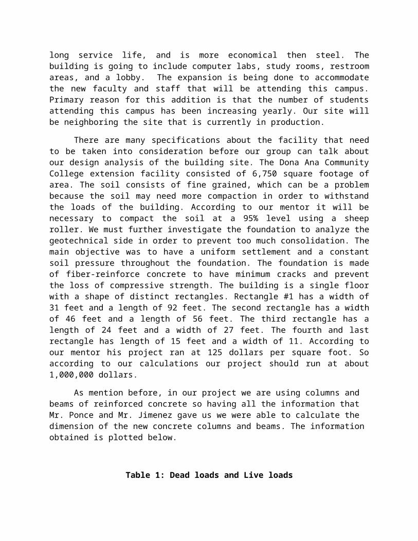
Our group decided to design the entire structural aspect of the building. Our project will be of concrete tilt-top panels with steel joists, reinforced concrete beams and columns. We have also considered the interior partitions of the structure and the some of the environmental sustainable aspects to minimize utility bills and improve efficiency. We designed columns and beams made out of reinforced concrete to provide considerable compressive strength, it also has great resistance to water and fire, has a long service life, and is more economical then steel. The building is going to include computer labs, study rooms, restroom areas, and a lobby. The expansion is being done to accommodate the new faculty and staff that will be attending this campus. Primary reason for this addition is that the number of students attending this campus has been increasing yearly. Our site will be neighboring the site that is currently in production.
There are many specifications about the facility that need to be taken into consideration before our group can talk about our design analysis of the building site. The Dona Ana Community College extension facility consisted of 6,750 square footage of area. The soil consists of fine grained, which can be a problem because the soil may need more compaction in order to withstand the loads of the building. According to our mentor it will be necessary to compact the soil at a 95% level using a sheep roller. We must further investigate the foundation to analyze the geotechnical side in order to prevent too much consolidation. The main objective was to have a uniform settlement and a constant soil pressure throughout the foundation. The foundation is made of fiber-reinforce concrete to have minimum cracks and prevent the loss of compressive strength. The building is a single floor with a shape of distinct rectangles. Rectangle #1 has a width of 31 feet and a length of 92 feet. The second rectangle has a width of 46 feet and a length of 56 feet. The third rectangle has a length of 24 feet and a width of 27 feet. The fourth and last rectangle has length of 15 feet and a width of 11. According to our mentor his project ran at 125 dollars per square foot. So according to our calculations our project should run at about 1,000,000 dollars.
As mention before, in our project we are using columns and beams of reinforced concrete so having all the information that Mr. Ponce and Mr. Jimenez gave us we were able to calculate the dimension of the new concrete columns and beams. The information obtained is plotted below.
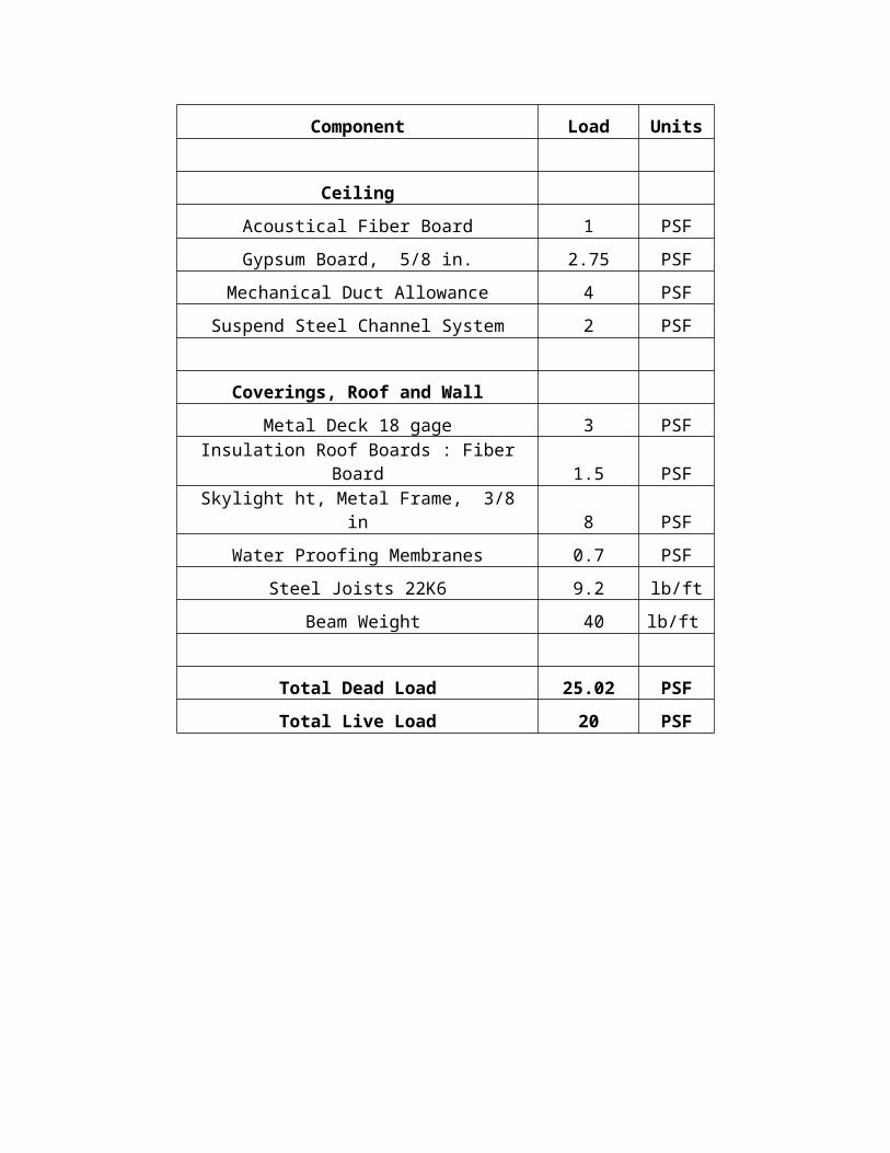
Table 1: Dead loads and Live loads
Component Load Units
Ceiling
Acoustical Fiber Board 1 PSF
Gypsum Board, 5/8 in. 2.75 PSF
Mechanical Duct Allowance 4 PSF
Suspend Steel Channel System 2 PSF
Coverings, Roof and Wall
Metal Deck 18 gage 3 PSF
Insulation Roof Boards : Fiber Board 1.5 PSF
Skylight ht, Metal Frame, 3/8 in 8 PSF
Water Proofing Membranes 0.7 PSF
Steel Joists 22K6 9.2 lb/ft
Beam Weight 40 lb/ft
Total Dead Load 25.02 PSF
Total Live Load 20 PSF

Structural Analysis:
Our mentor provided us with a table of dead loads and live loads that is provided below. To obtain the dead load of the building a complete analysis of the building was done. Using the AutoCAD file the position of the beams and steel joists were designed throughout the building. Once this was done the calculation of the total roof dead load preceded, all the pressures acting on the roof were gathered as were the assumed beam weight and steel joist weight. The assumed beam weight and steel joists weight were in units of weight per linear foot. In order to obtain the total roof dead load all the point loads would be calculated beforehand. For example with the pressures I multiplied the tributary area of the entire structure with all the pressures and obtained a point load. This was also done with the reinforced concrete beams and the steel joists once all the point loads were calculated they were added and then divided by the tributary area of the structure, the value obtained was the total roof dead load. The dead load obtained was then used to design a beam once the dimensions of the reinforced concrete beam were obtained the beam weight was checked. The beam weight was then different from the assumed, so the roof dead load was then recalculated with the new beam weight, this process was also used with the steel joists. After much calculation the total roof dead load obtained was 25 lb/ft2
.
Since our structure is in El Paso we must also consider the wind forces that the structure is going to be exerting. The wind loads will only be considered on the walls of the structure since they are external forces. So having all the tools that we have obtained thru all the civil engineering courses we were able to calculate the structural analysis of our project.
Beams:
The Beam was designed thanks to the Design of Reinforced Concrete eighth edition by Jack C. McCormac and Russell H. Brown. Our Beams will be rectangular the dimensions will be as follows, the height will be 12’’ and the base will be 18’’. The grade of steel that will be used is 60 ksi, and the concrete will have a strength 4 ksi. When I applied the ØR n equation the value was too great and wasn’t found on the tables, meaning the beam needed double reinforcement. The distributed load the beam is carrying is 1.77 k/ft, along the 31 ft span. The moment of the beam was 212.62 kip*ft, I then applied the ØRn equation which allows one to find the ductility of the steel in the concrete. Once this value is obtained the ductility can be approximated with a table. The area of steel in the concrete came out to be 4 in2. The rebar that is used on the bottom section is 4#9. The equations used for the area of steel on the beams were as follows. The deflection on the beam was 0.21in. and the maximum deflection for the span of the beam was 1.03in.
Moment:
Mu=WuL 2 8 Wu= distributed loadL= Span of beam
This formula is used to get the ductility of steel:
ØRn=Mu__ Øbd2
Ø= 0.9, (Constant)b= based= depth
Area Steel:
As= ρbd
ρ = ductility of steel
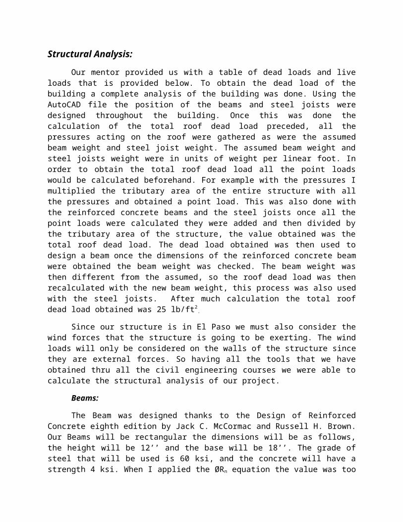
Equilibrium equation used to solve c: Asfy=0.85f’cβcb + As( c-d )εsEs c f’c= compressive strength of concrete, ksify = tensile strength of steel, ksiβ= 0.85, (constant)c= distance of neutral axis of beam, in.a= distance of compressive force on beam, in.εs = strain steel yields at, 0.003Es= modulus of elasticity of steel, 29,000 ksi
Deflection:
∆=5wL 4 384EI
w= Distributed Load, kip per linear footL= span of the beamE= Modulus of elasticity of concrete
∆max=__L__ 3
Wu= 1.77 k/ft
Figure 1: Beam distributed load and As
4#9
Figure 2: Side view of beam dimensions and As
Columns:
We decided to place our columns at an average of 30 feet from each other, in some areas exceptions were made. The grade of steel that will be used is 60 ksi, and the concrete will have a strength 4 ksi. The load that the column with the greatest tributary area withstood was 55k and the moment was 170.1k-ft. The dimensions of the Columns we will use are 12’’ by 16’’. The column was designed thanks to the Design of Reinforced Concrete eighth edition by Jack C. McCormac and Russell H. Brown. Once the column was designed the slenderness of the member was checked, with the slenderness ratio. The member was in fact slender, this caused a check for a moment magnification. The moment magnification was 1.07 and when multiplied to the moment increased it to 182k-ft. The moment magnification changed the original area of steel which was 6.5 in2 and after the magnification the area changed to 7.68 in2. The amount of rebar that will be used is 8 number 9 bars for each column, the final area of steel is 8in2.
DL =25.05 psf
4#9
18 in.
12in.
2 in.
LL = 20 psff’c =4000 psify = 60,000 psi
Factor Load equation:
Pu = (1.2)(DL) +(1.6)(LL)
Pu = (1.2)(25.05) +(1.6)(20) Pu =62.06 psf
Factors used for selection of percentage of steel on column:
Kn = Pn____
f’c Ag
Kn= ratio used for percentage of steelPn = the nominal force, in kipsAg = Gross Areaf’c = Strength of concrete, ksi
Rn= Pn e____
f’c Ag hRn= ratio used for percentage of steele= eccentricity, in.h= height of column, in.
Slenderness Ratio:
KL < 34- 12( M 1) r M2
K= effective length factor, ratioL= length of memberr= radius of gyrationM1= smaller factored end moment M2= greater factored end moment
The following equations were used for the moment magnification:

Pc= π 2 EI ( KL)2
Pc= Euler buckling loadEI= value that accounts for creep, cracks, and so on, ksi.
EI= (0.2Ec Ig + Es Ise) 1 + βdns
Ec= modulus of elasticity of concreteIg= gross moment of inertiaEs= modulus of elasticity of steelIse=moment of inertia of the reinforcing about the centroidal axisβdns= accounts for the reduction of stiffness, ratio
Cm= 0.6 + 0.4( M 1) M2
Cm= modification factor
δ= ___C m_____
1- _Pu__
0.75 Pc
δ= magnification factor
Mc= δM2
Mc= magnified moment
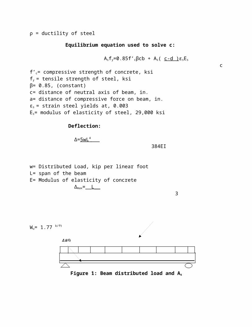
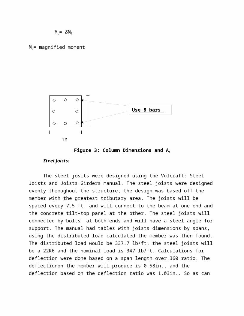
Figure 3: Column Dimensions and As
Steel Joists:
The steel josits were designed using the Vulcraft: Steel Joists and Joists Girders manual. The steel joists were designed evenly throughout the structure, the design was based off the member with the greatest tributary area. The joists will be spaced every 7.5 ft. and will connect to the beam at one end and the concrete tilt-top panel at the other. The steel joists will connected by bolts at both ends and will have a steel angle for support. The manual had tables with joists dimensions by spans, using the distributed load calculated the member was then found. The distributed load would be 337.7 lb/ft, the steel joists will be a 22K6 and the nominal load is 347 lb/ft. Calculations for deflection were done based on a span length over 360 ratio. The deflectionon the member will produce is 0.58in., and the deflection based on the deflection ratio was 1.03in.. So as can be seen the deflection on the member met the required deflection based on the length.
Deflection:
∆=5wL 4 384EI
w= Distributed Load, kip per linear footL= span of the beam, in.E= Modulus of elasticity of concrete, ksi.∆= Deflection, in.
∆max=__L__ 360
16”
12” Use 8 bars #9

Reinforced Concrete Tilt-up Walls:
Reinforced concrete tilt-up panels are design mainly for industrial applications since it is an economical and fast process when built and placed. Tilt-ups can be made in the job site or prefabricated in a machine shop. Usually most general contractors and owners preferred the prefabricated version of the tilt up since it will has less flaws than the one at the job site. Tilt-ups tend to be very durable, they have minimal maintenance cost, they are easy to replace, and the concrete and steel of the tilt-up can be recyclable. In this section of the report, the process on how to design concrete tilt-up panels such as concrete mix, placing, floor slab design, wall design, and the use of bond breakers will be mention. Keep in mind that in order for the concrete tilt-ups to be economical, there can be a reversing decision on the design because it can create a chain reaction that would necessitate reconsidering all of the following previous decisions.
Concrete mix design can be made of architectural mixes and structural mixes. Structural mixes are made of local concrete companies. Architectural mixes are good for uniform color, which usually the cement and the sand are obtained from a single source, for visual appearances. The main objective is to have a proportional concrete mix. The main ingredients for the concrete tilt-up are: Portland cement, fly ash, coarse aggregate, sand, admixture, and may be air entraining agent. Concrete casting method consists of molding floor slabs, wall footings, column footings, interior columns before installing concrete tilt-up panels. Floor slabs can be treated as casting platforms and they provide support for the crane during panel erection. Floor slabs must have a thickness of five to six inches, compacted at the sub grade to provide no sagging support for the crane during the lifting operation as seen in figure 1. The surface of the floor slab must be perfectly level, smoothly troweled because any fault in the floor will be reflected on the wall panels. Proper curing of the concrete provides uniform slab surface, prevent plastic shrinkage cracks, curling, and dusting. Floor joist should be designed to occur between the cast panels.
Figure 4: Concrete Tilt-up Wall at Lifting Operation
Wall panels must be cast horizontally and treat them with special care to prevent rock pockets along the bottom of the edge forms. Wall panels must be well consolidated with no air pockets around the reinforcements of the lifting inserts which tilt-ups can lose lift strength, collapse during the lift. Overturned lifting inserts should also be taking in consideration along with the inserts which should be balance and secured. If inserts are off balance at even small angle, their strength of lifting stresses may be limited and they may fail. Tilt-ups are cast either
exterior face up or face down according to the position of the panel face receiving the finish. Exterior face is where its expose to the outside environment.
Bond breakers are substances that permit clean separations of precast members from the casting slabs. Common bond breakers are synthetic petroleum hydrocarbon resin solutions, waxes with metallic soaps, and organic esters and silicones. Resins are used when the bleed water of the concrete has disappeared, while waxes and organic esters are placed right when the concrete is fresh in order to provide an early moisture loss protection. When placing bond breakers, one must consider weather, slab use, and technical assistance. Innumerable colors and textures are obtainable with architectural concrete in tilt-up construction. The simplest treatment is to paint a plain panel surface. Panels can also be made of sandblast, pattern, smooth-troweled, and dimpled effect. A sheet of polyethylene is placed between of gravel and the concrete panel face, giving surface smoothness, glossy appearance.
In the design phase of the tilt-up walls, the critical moment occurs in when the tilt-up is being lift. Figure 2 shows how to make a structural analysis procedure when a crane is lifting a tilt-up panel. Our group decided to use an average length of 15 feet and height of 19 feet for each panel. The length of certain panels will vary because of the structure of the building. Next, our group determines the lift point inserts and the brace inserts for the crane to lift the concrete tilt-up wall. The dimensions are shown in figure 3. The maximum stress at lift is about 72.9 psi and the angles where the maximum stress might occur is approximately at 20 and 40 degrees from the ground. Figure 1 portrays a concrete tilt-up wall being lift from the ground to its permanent location in a building structure.
Figure 5: Concrete Tilt-up Analysis Procedure
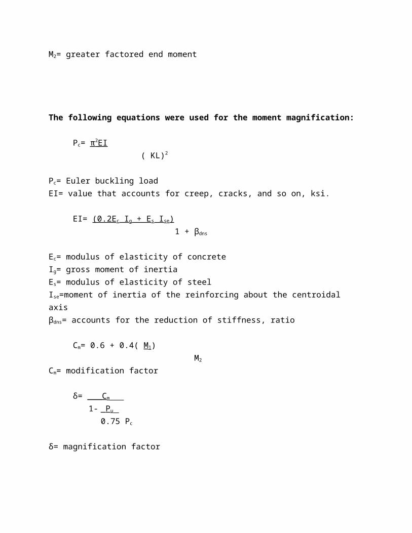
Figure 6: Shear and Moment Diagram for Tilt-Up Wall
Interior Partitions:
The interior partitions of the building are going to be composed of metal studs, insulation and plasterboard. Steel framing is commonly used in commercial construction, and that is because it has several advantages over wood. Among those advantages we have that steel studs are perfectly straight, they do not shrink or split, they are light and easy to store, plus they resist fire, insects and rot. Another advantage for the construction is that they are also easier to move correct for changes over the original design. The overall cost between steel framing and wood framing is about the same. One of the disadvantages for metal framing construction is that for heavy cabinets such as overhead kitchen cabinets, they may not be strong enough to support the weight, even with drywall on them.
For this particular building design an estimation of the materials was made from the original floor plans. After the respective calculations were performed and the results were checked, we found that there is a need for 360 linear feet of interior walls. The approximation of all the materials was made accounting for 10 ft high walls. Since we have 360 linear feet of walls we then will need 720 linear feet of metal tracks, accounting for the top and bottom of the walls, 270 pieces of 10 feet high metal studs, 3600 square feet of R-19 insulation, and 7200 square feet of plasterboard to cover both sides of the walls. All this values are approximated values not
including any changes in the original design, and assuming zero losses from the manufacture process.

Figure 4: The dimensions of the site
Columns
Beams
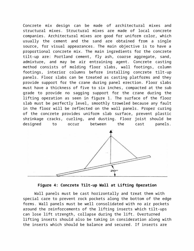
Table 2. Dead Load
Table 3. Dead Loads Continue.