domss.doosaninfracore - t-support.cz · PUMA MX 2000/2500 series 3 B & Y-axis performance B&Y-axis...
20
domss.doosaninfracore.com Multi-Axis Turning Center
Transcript of domss.doosaninfracore - t-support.cz · PUMA MX 2000/2500 series 3 B & Y-axis performance B&Y-axis...

domss.doosaninfracore.com
Multi-Axis Turning Center
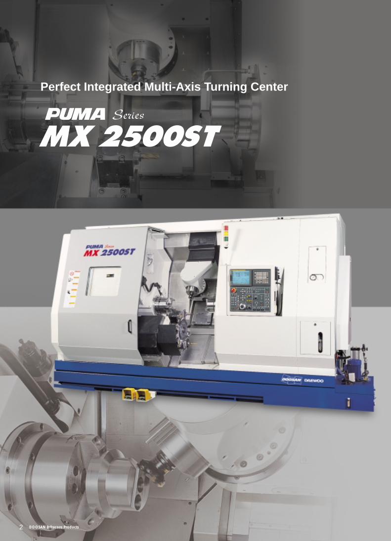
Perfect Integrated Multi-Axis Turning Center
2 DOOSAN Infracore Products
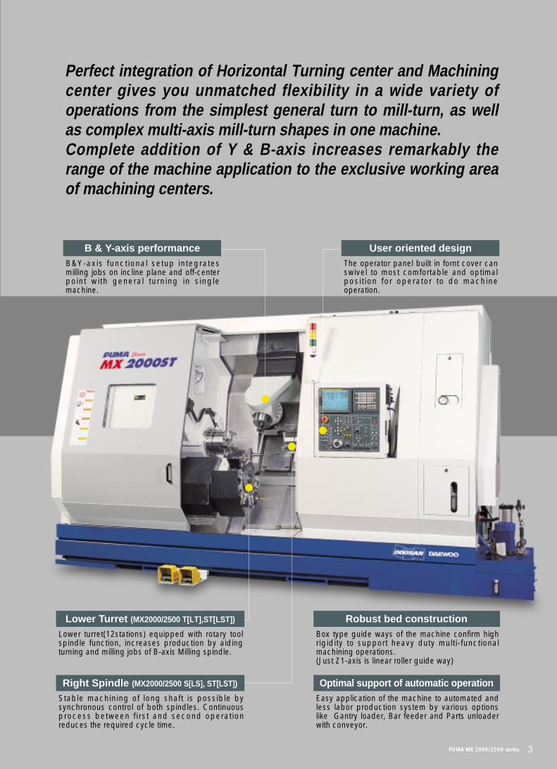
Perfect integration of Horizontal Turning center and Machiningcenter gives you unmatched flexibility in a wide variety ofoperations from the simplest general turn to mill-turn, as wellas complex multi-axis mill-turn shapes in one machine. Complete addition of Y & B-axis increases remarkably therange of the machine application to the exclusive working areaof machining centers.
PUMA MX 2000/2500 series 3
B & Y-axis performanceB&Y-axis functional setup integratesmilling jobs on incline plane and off-centerpoint with general turning in singlemachine.
Lower Turret (MX2000/2500 T[LT],ST[LST])
Lower turret(12stations) equipped with rotary toolspindle function, increases production by aidingturning and milling jobs of B-axis Milling spindle.
Robust bed construction Box type guide ways of the machine confirm highrigidity to support heavy duty multi-functionalmachining operations.(Just Z1-axis is linear roller guide way)
Optimal support of automatic operationEasy application of the machine to automated andless labor production system by various optionslike Gantry loader, Bar feeder and Parts unloaderwith conveyor.
Right Spindle (MX2000/2500 S[LS], ST[LST])
Stable machining of long shaft is possible bysynchronous control of both spindles. Continuousprocess between first and second operationreduces the required cycle time.
User oriented designThe operator panel built in fornt cover canswivel to most comfortable and optimalposit ion for operator to do machineoperation.
Both Left and Right spindle are designedto minimize the mal-effects of thermaldistortion which can hit continuousmachining precision seriously and toensure remarkable range of applicationsfrom heavy duty cutting with high powerat low speed to fine finish cutting at highspeed.
C1-axisC1-axis C2-axis
4 DOOSAN Infracore Products
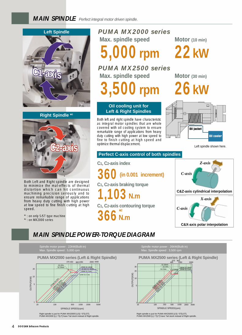
5,000 rpmMax. spindle speedPUMA MX2000 series
22kWMotor (10 min)
3,500 rpmMax. spindle speedPUMA MX2500 series
26kWMotor (30 min)
Left Spindle
C1-axis C2-axisC2-axis
Right Spindle *1
MAIN SPINDLE Perfect integral motor driven spindle.
Oil cooling unit forLeft & Right Spindles
Perfect C-axis control of both spindles
Both left and right spindle have characteristicas integral motor spindles that are wholecovered with oil cooling system to ensureremarkable range of applications from heavyduty cutting with high power at low speed tofine to finish cutting at high speed andoptimize thermal displacement.
·Left spindle shown here.
MAIN SPINDLE POWER-TORQUE DIAGRAM
360。(in 0.001。。increment)
C1, C2-axis index
1,103 N.m
*2
366N.m
C1, C2-axis braking torque
C1, C2-axis contouring torque
*1 : on only S/ST type machine*2 : on MX2000 series
C&Z-axis cylindrical interpolation
C&X-axis polar interpolation
Z-axis
X-axis
C-axis
C-axis
2000100020
5
100
10
1
20
370 450 1050
500
15kW S1 Cont.
11KW S1 Cont.
477N
m S3 2
5%
318N
m S2 2
0min
233N
m S1 C
ont.
SPINDLE SPEED(rpm)
OU
TPU
T(K
W)
5000
2800 4400
200N
m S2 1
0min
168N
m S2 3
0min
136N
m S1 C
ont.
22kW S2 10min18.5kW S2 30min
800
S3 25%S2 20min
●Spindle motor power : 22kW(Built-in)●Max. Spindle speed : 5,000 rpm
※Right spindle is just for PUMA MX2000S [LS] / ST[LST]. PUMA MX2000 [L] / T[LT] have Tail stock instead of Right spindle.
20
1
10
100 250
5
30
1000 2000 3500
15KW
22KW S1 Cont.
433N
m S3 2
5%
369N
m S2 3
0min
296N
m S1 C
ont.
200N
m S1 C
ont.
237N
m S2 3
0min
SPINDLE SPEED(rpm)
OU
TPU
T(K
W)
1050 3000485570 900
50020
26KW S2 30min22KW
S3 25%S2 30min
S1 Cont.
●Spindle motor power : 26kW(Built-in)●Max. Spindle speed : 3,500 rpm
※Right spindle is just for PUMA MX2500S [LS] / ST[LST]. PUMA MX2500 [L] / T[LT] have Tail stock instead of Right spindle.
PUMA MX2000 series (Left & Right Spindle) PUMA MX2500 series (Left & Right Spindle)
PUMA MX 2000/2500 series 5
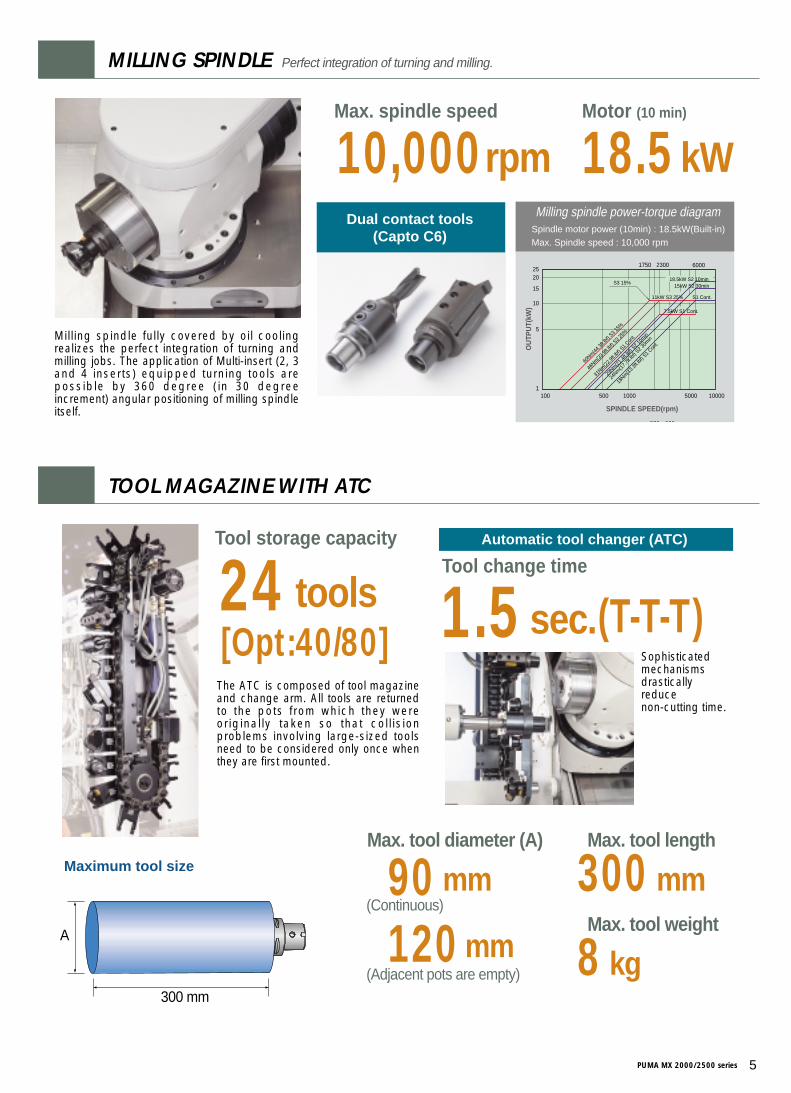
Dual contact tools(Capto C6)
Milling spindle fully covered by oil coolingrealizes the perfect integration of turning andmilling jobs. The application of Multi-insert (2, 3and 4 inserts) equipped turning tools arepossible by 360 degree (in 30 degreeincrement) angular positioning of milling spindleitself.
20
31Nm(2
2.9ft.l
bf) S
1 Con
t.
46Nm(3
3.9ft.l
bf) S
3 25%
60Nm(4
4.3ft.l
bf) S
3 15%
7.5kW S1 Cont.
11kW S3 25%
15
10
5
5000
2300 6000
1100
1750
1000500 10000
25
18.5kW S2 10min15kW S2 30min
S1 Cont.
29Nm(2
1.4ft.l
bf) S
2 10m
in
24Nm(1
7.7ft.l
bf) S
2 30m
in
18Nm(1
3.3ft.l
bf) S
1 Con
t.OU
TPU
T(kW
)
SPINDLE SPEED(rpm)
S3 15%
570 900
■Milling spindle power-torque diagram●Spindle motor power (10min) : 18.5kW(Built-in)●Max. Spindle speed : 10,000 rpm
MILLING SPINDLE Perfect integration of turning and milling.
TOOL MAGAZINE WITH ATC
10,000rpmMax. spindle speed
18.5kWMotor (10 min)
24[Opt:40/80]
toolsTool storage capacity
1.5 (T-T-T)sec.Tool change time
Automatic tool changer (ATC)
A
300 mm
The ATC is composed of tool magazineand change arm. All tools are returnedto the pots from which they wereoriginally taken so that coll isionproblems involving large-sized toolsneed to be considered only once whenthey are first mounted.
Sophisticated mechanisms drastically reduce non-cutting time.
••Maximum tool size Ø90 mm••Max. tool diameter (A)
300 mm••Max. tool length
8 kg••Max. tool weight
(Continuous)
Ø120 mm(Adjacent pots are empty)
6 DOOSAN Infracore Products
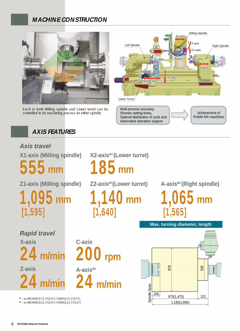
MACHINE CONSTRUCTION
Max. turning diameter, length
973(1,473)156
Ø97
8
Spi
ndle
Nos
e
Ø53
5
222
1,195(1,695)
555mm
X1-axis (Milling spindle)
185mm
X2-axis*1 (Lower turret)
1,095[1,595] [1,640] [1,565]
mm
Z1-axis (Milling spindle)
1,140 mm
Z2-axis*1(Lower turret)
1,065 mm
A-axis*2 (Right spindle)
Left Spindle
Lower Turret
Milling Spindle
Right Spindle
X2-axisZ2-axis
C1-axis C2-axisB-axis
A-axis
Z1-axis
Y-axis
X1-axis
X2-axisZ2-axis
C1-axis C2-axisB-axis
A-axis
Z1-axis
Y-axis
X1-axis
AXIS FEATURES
Each or both Milling spindle and Lower turret can becontrolled to do machining process on either spindle.
Axis travel
24 m/minX-axis
200 rpm
C-axis
24 m/min
Z-axis
24 m/min
A-axis*2
Rapid travel
*1 : on MX2000T[LT], ST[LST] / 2500T[LT], ST[LST]
*2 : on MX2000S[LS], ST[LST] / 2500S[LS], ST[LST]
Multi-process accuracy, Shorten setting times, Optimal distribution of cycle and Automated operation support
Achievement ofPUMA MX machines
PUMA MX 2000/2500 series 7
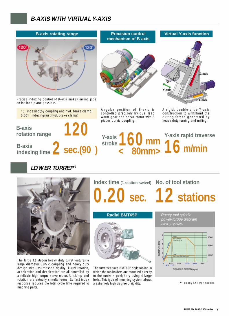
160mmsec.(90。。) <±±80mm>
Y-axis stroke
±120。B-axis rotation range
2B-axis indexing time 16 m/min
Y-axis rapid traverse
B-axis rotating range
B-AXIS WITH VIRTUAL Y-AXIS
LOWER TURRET*1
Precise indexing control of B-axis makes milling jobson inclined plane possible.
Ys-axis
X1-axis
Y-axis
Ys-axis
X1-axis
Y-axis
Virtual Y-axis function
A rigid, double-slide Y-axisconstruction to withstand thecutting forces generated byheavy duty turning and milling.
Precision control mechanism of B-axis
Angular posit ion of B-axis iscontrolled precisely by dual leadworm gear and servo motor with 3pieces curvic coupling.
•15。indexing(by coupling and hyd. brake clamp)•0.001。indexing(just hyd. brake clamp)
0.20 sec.Index time (1-station swivel)
12 stationsNo. of tool station
The large 12 station heavy duty turret features alarge diameter Curvic coupling and heavy dutydesign with unsurpassed rigidity. Turret rotation,acceleration and deceleration are all controlled bya reliable high torque servo motor. Unclamp androtation are virtually simultaneous. Its fast indexresponse reduces the total cycle time required tomachine parts.
0
1
2
3
4
5
6
1000 2000 3000 4000 5000
5.5kW
3.7kW
1.5kW
1115425
5.5kW
(15min, S3 60%
1.5kW(Continuous Operating Zone)
47 N
.m
33.7
N.m
Opearting Zone)
SPINDLE SPEED (rpm)
OU
TPU
T (k
W )
■Rotary tool spindlepower-torque diagram
● 4,000 rpm(5.5kW)
Radial BMT65P
The turret features BMT65P style tooling inwhich the toolholders are mounted directiyto the turret's periphery using 4 largebolts. This type of mounting system allowsa extremely high degree of rigidity. *1 : on only T/ST type machine

8 DOOSAN Infracore Products
MACHINING CAPACITY
■Workpiece material, KS(JIS) : SM45C(S45C), Carbon steel■The cutting test results indicated above are obtained as an
example through real test cutting.■The results may not be obtained due to differences in cutting
and environmental conditions during measurement.
Heavy duty cutting (OD) Milling 1 (Face Milling)
Milling 2 (End Milling)
Milling 3 (Drilling)
Spindle speed
Cutting speed
Feedrate
485 rpm
150 m/min
0.4 mm/rev
Tool
Cutting depth
Feedrate
Millingspindle speed 800 rpm
Ø80 mm (6Z)
480 mm/min
2.5 mm
Tool
Cutting depth
Feedrate
Millingspindle speed
Tool (U-Drill)
Feedrate
Millingspindle speed
380 rpm
Ø25 mm
160 mm/min
20 mm
1,800 rpm
Ø40 mm
0.15 mm/rev
9mmCutting depth
550 cm3/minChip removal rate
Widely spaced guide ways and heavy-duty design of tailstock bodyensure ample rigidity. The tailstock body is positioned by a drivebar, which engages with the carriage. The drive bar movement andhydraulic body clamping with guide way are programmable. Itsbuilt-in dead center ensures the high rotating support of workpiece.
Tail stock body travel mm 1,015[1,375] (870[800])*2
Tail stock quill type MT#4(Built-in dead)Tail stock quill diameter mm 100Tail stock quill travel mm 150Tail stock quill thrust force N 7,546 N
Programmable tail stock specifications
PROGRAMMABLE TAIL STOCK*1
*1 : Progrmmable tail stock with built-in dead center is standard on only MX2000[L],T[LT] and MX2500[L],T[LT]*2 : on only MX2000T[LT]/2500T[LT]
PUMA MX 2000/2500 series 9
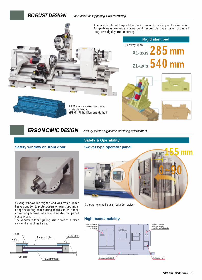
Safety & Operability
Safety window on front door Swivel type operator panel
Viewing window is designed and was tested underheavy condition to protect operator against possibledangers during real cutting thanks to its shockabsorbing laminated glass and double panelconstruction. The window without grating also provides a clearview of the machine inside.
ERGONOMIC DESIGN Carefully tailored ergonomic operating environment.
Resin
NBR
Out side
Tempered glass
Polycarbonate
Metal plate
High maintainabilityPressure control
for Left spindlechucking
Pressure controlfor Right spindlechucking (or Tail stock)
Separate coolant tank Lubrication tank
Operator oriented design with 90。swivel
155mmJust
0~90。
FEM analysis used to design a stable body. (FEM : Finite Element Method)
The heavily ribbed torque tube design prevents twisting and deformation.All guideways are wide wrap-around rectangular type for unsurpassedlong-term rigidity and accuracy.
Rigid slant bedGuideway span
285 mmX1-axis
540 mmZ1-axis
ROBUST DESIGN Stable base for supporting Multi-machining.
10 DOOSAN Infracore Products
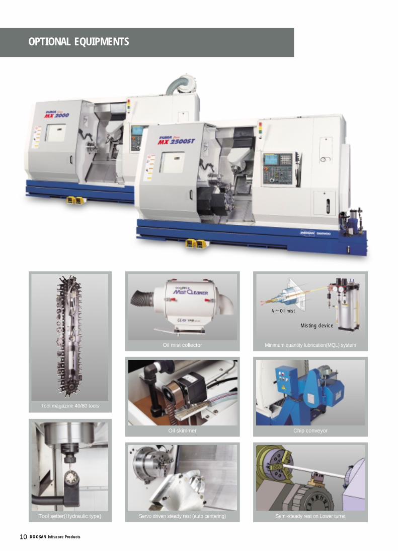
OPTIONAL EQUIPMENTS
Tool setter(Hydraulic type)
Tool magazine 40/80 tools
Oil skimmer
Servo driven steady rest (auto centering) Semi-steady rest on Lower turret
Oil mist collector
Chip conveyor
Minimum quantity lubrication(MQL) system
Misting device
Air+Oil mist
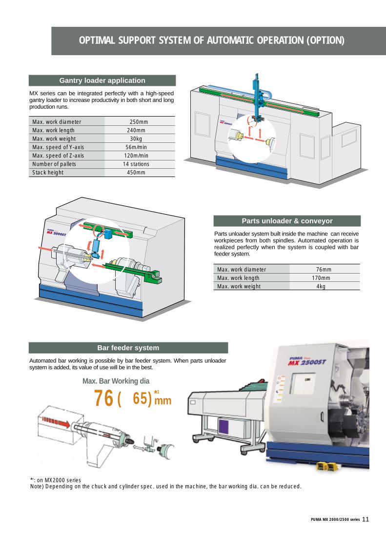
OPTIMAL SUPPORT SYSTEM OF AUTOMATIC OPERATION (OPTION)
MX series can be integrated perfectly with a high-speedgantry loader to increase productivity in both short and longproduction runs.
Gantry loader application
Max. work diameter Ø250mmMax. work length 240mmMax. work weight 30kgMax. speed of Y-axis 56m/minMax. speed of Z-axis 120m/minNumber of pallets 14 stationsStack height 450mm
Automated bar working is possible by bar feeder system. When parts unloadersystem is added, its value of use will be in the best.
Bar feeder system
Parts unloader system built inside the machine can receiveworkpieces from both spindles. Automated operation isrealized perfectly when the system is coupled with barfeeder system.
Parts unloader & conveyor
Max. work diameter Ø76mmMax. work length 170mmMax. work weight 4kg
*1: on MX2000 seriesNote) Depending on the chuck and cylinder spec. used in the machine, the bar working dia. can be reduced.
*1Ø76(Ø65) mm
Max. Bar Working dia
PUMA MX 2000/2500 series 11
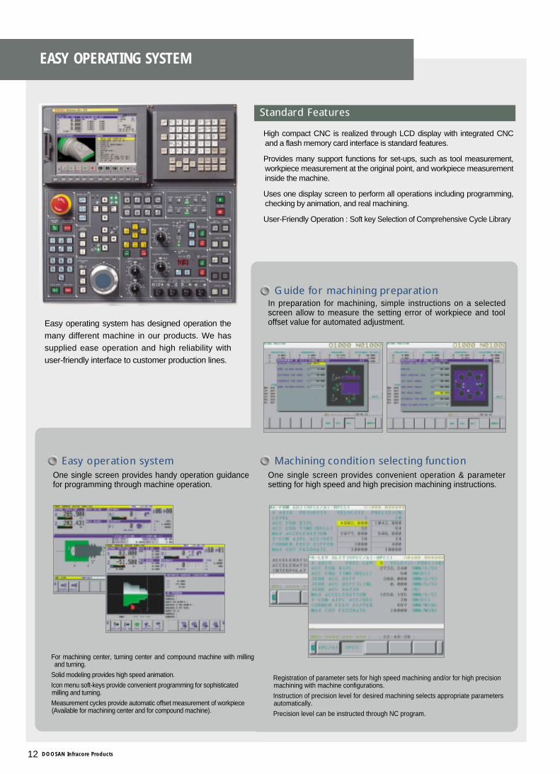
Easy operating system has designed operation themany different machine in our products. We hassupplied ease operation and high reliability withuser-friendly interface to customer production lines.
■High compact CNC is realized through LCD display with integrated CNCand a flash memory card interface is standard features.
■Provides many support functions for set-ups, such as tool measurement,workpiece measurement at the original point, and workpiece measurementinside the machine.
■Uses one display screen to perform all operations including programming,checking by animation, and real machining.
■User-Friendly Operation : Soft key Selection of Comprehensive Cycle Library
Standard Features
■For machining center, turning center and compound machine with millingand turning.
■Solid modeling provides high speed animation.
■Icon menu soft-keys provide convenient programming for sophisticated milling and turning.
■Measurement cycles provide automatic offset measurement of workpiece (Available for machining center and for compound machine).
■Registration of parameter sets for high speed machining and/or for high precision machining with machine configurations.
■Instruction of precision level for desired machining selects appropriate parameters automatically.
■Precision level can be instructed through NC program.
Easy operation systemOne single screen provides handy operation guidancefor programming through machine operation.
Guide for machining preparationIn preparation for machining, simple instructions on a selectedscreen allow to measure the setting error of workpiece and tooloffset value for automated adjustment.
One single screen provides convenient operation & parametersetting for high speed and high precision machining instructions.
Machining condition selecting function
EASY OPERATING SYSTEM
12 DOOSAN Infracore Products
unit : mm
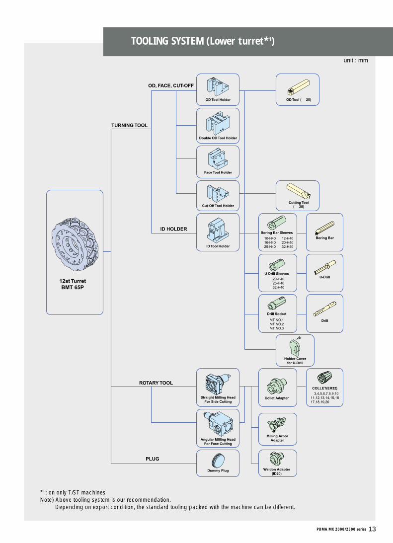
*1 : on only T/ST machinesNote) Above tooling system is our recommendation.
Depending on export condition, the standard tooling packed with the machine can be different.
Double OD Tool Holder
12st TurretBMT 65P
TURNING TOOL
OD, FACE, CUT-OFF
ID HOLDER
ROTARY TOOL
PLUG
OD Tool (□25)
Cutting Tool(□25)
Boring Bar Sleeves
Ø10-H40Ø16-H40Ø25-H40
Ø20-H40Ø25-H40Ø32-H40
Ø3,4,5,6,7,8,9,1011,12,13,14,15,1617,18,19,20
Ø12-H40Ø20-H40Ø32-H40
Boring Bar
U-DrillU-Drill Sleeves
Drill
Holder Coverfor U-Drill
Drill Socket
MT NO.1MT NO.2MT NO.3
Straight Milling HeadFor Side Cutting
COLLET(ER32)
Collet Adapter
Angular Milling HeadFor Face Cutting
Dummy Plug
Milling ArborAdapter
Weldon Adapter(ID20)
OD Tool Holder
Face Tool Holder
Cut-Off Tool Holder
ID Tool Holder
TOOLING SYSTEM (Lower turret*1)
PUMA MX 2000/2500 series 13
unit : mm
3
[1565] (A-Stroke)1065142 [1045]545 497 17 142
45
65
45
65
150
555
(X1-
Stro
ke)
10
¿210
15.5145 [1595] (Z1-Stroke)1095
[775] (Z1-Ref Point)525
16.5142 [1100]600 497
2053
5
220
335
200
[1755.5]1255.5
[1375] (T/S Stroke)1015
220
335
200
2053
5
[775] (Z1-Ref Point)525
103145 [1595] (Z1-Stroke)1095
¿210
¿210
[1843]1343
10
555
(X1-
Stro
ke)
8" CHUCK8" CHUCK
8" CHUCK
3
¿254
[1565] (A-Stroke)1065
45
65
45
65
555
(X1-
Stro
ke)
555
(X1-
Stro
ke)
[1755.5]1255.5
150 [1375] (T/S Stroke)1015
15.5145 [1595] (Z1-Stroke)1095
[775] (Z1-Ref Point)525
16.5156 [1086]586 497
535
20
10
220
335
200
¿254
¿254
220
335
200
10
535
20
9156 [1025]525 497 156
[775] (Z1-Ref Point)525
145 [1595] (Z1-Stroke)1095 103
[1843]1343
10" Chuck
10" Chuck
10" Chuck
PUMA MX2000 PUMA MX2500
PUMA MX2000S PUMA MX2500S
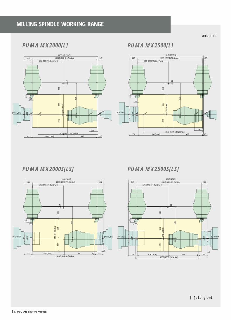
MILLING SPINDLE WORKING RANGE
14 DOOSAN Infracore Products
PUMA MX2000[L] PUMA MX2500[L]
PUMA MX2000S[LS] PUMA MX2500S[LS]
※[ ] : Long bed
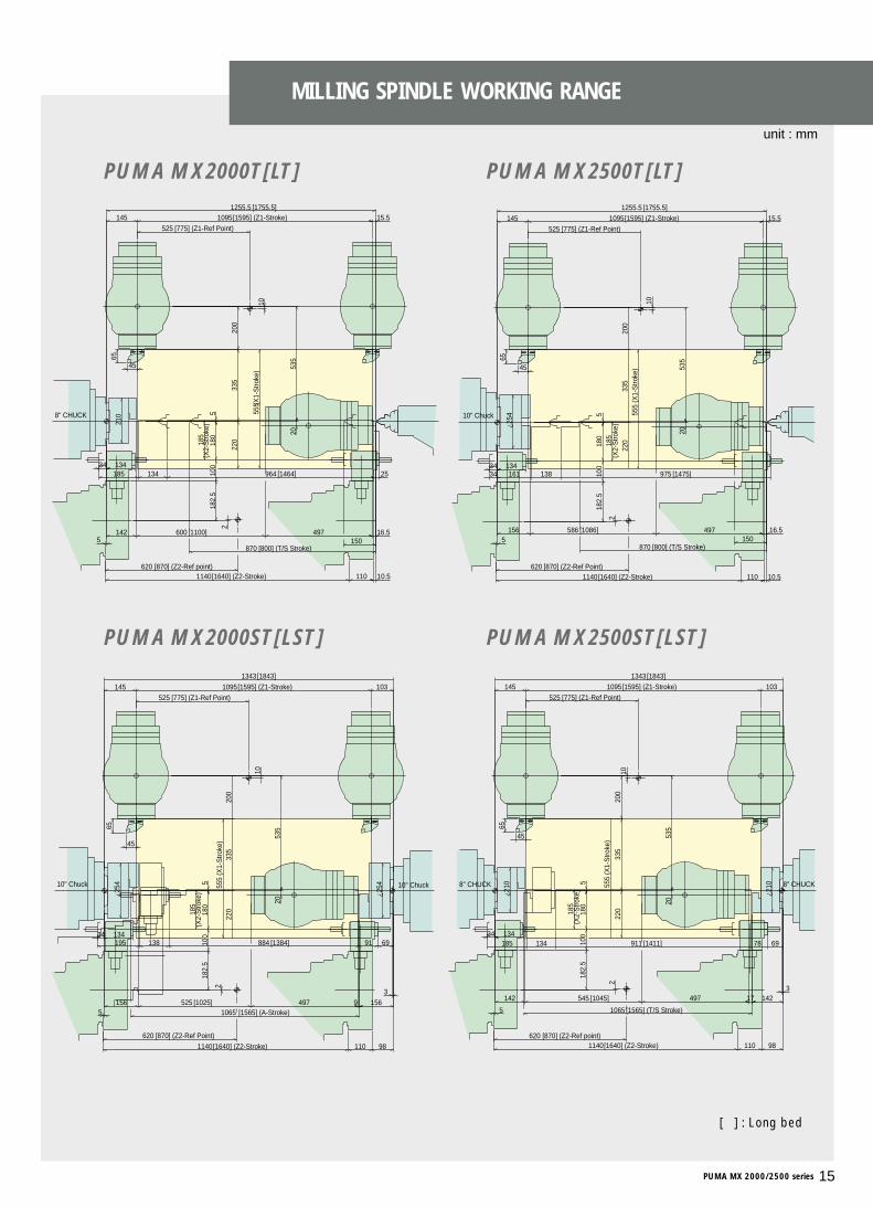
unit : mm
98110 [1640] (Z2-Stroke)1140 [870] (Z2-Ref point)620
5
2
2
10.5110 [1640] (Z2-Stroke)1140 [870] (Z2-Ref point)620
5
25 [1464]96413418513434
6978 [1411]91113418513434
3
[1565] (T/S Stroke)1065
45
65
45
65
150 [800] (T/S Stroke)870
[1755.5]1255.518
2.5
100
180
5
220
335
200
2053
5
16.5142 [1100]600 497
[775] (Z1-Ref Point)525
15.5145 [1595] (Z1-Stroke)1095
210
10(X
1-S
troke
)55
5
185
185
555
(X1-
Stro
ke)
10
[1843]1343
¿210
¿210
103145 [1595] (Z1-Stroke)1095
[775] (Z1-Ref Point)525
142 [1045]545 14217497
2053
5
220
335
200
182.
510
018
05 8" CHUCK8" CHUCK
8" CHUCK
(X2-
Stro
ke)
(X2-
Stro
ke)
2
13434
13434
[1475]97513816134
10.5110 [1640] (Z2-Stroke)1140 [870] (Z2-Ref Point)620
5
3
69 [1384]884 91138195
2
98110 [1640] (Z2-Stroke)1140
[870] (Z2-Ref Point)620
5
45
65
[1565] (A-Stroke)1065
¿254
[1843]1343
45
65
185
555
(X1-
Stro
ke)
185
555
(X1-
Stro
ke)
145 [1595] (Z1-Stroke)1095 103
[775] (Z1-Ref Point)525
9 156156 [1025]525 497
535
20
10
220
335
200
182.
510
018
05
¿254
¿254
182.
510
018
05
220
335
200
10
535
20
156 [1086]586 497 16.5
[775] (Z1-Ref Point)525
15.5145 [1595] (Z1-Stroke)1095
[1755.5]1255.5
[800] (T/S Stroke)870150
10" Chuck10" Chuck
10" Chuck
(X2-
Stro
ke)
(X2-
Stro
ke)
PUMA MX2000T PUMA MX2500T
PUMA MX2000ST PUMA MX2500ST
PUMA MX 2000/2500 series 15
MILLING SPINDLE WORKING RANGE
PUMA MX2000T[LT] PUMA MX2500T[LT]
PUMA MX2000ST[LST] PUMA MX2500ST[LST]
※[ ] : Long bed
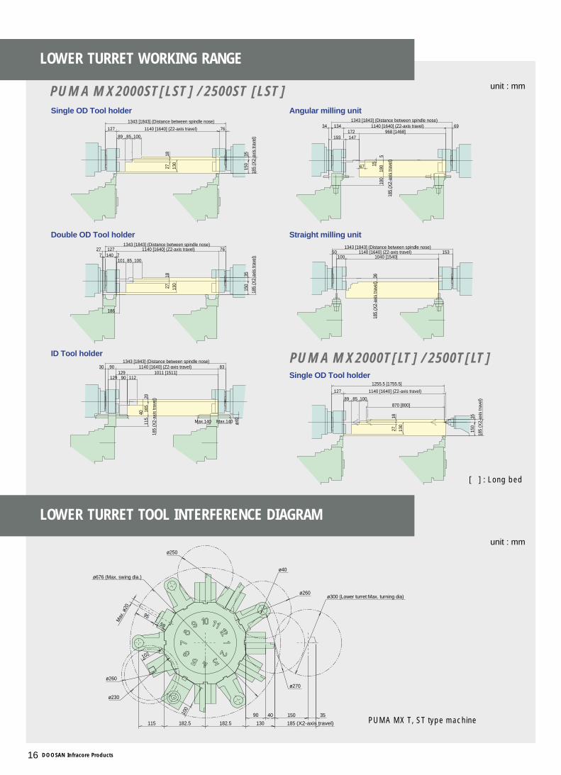
LOWER TURRET WORKING RANGE
16 DOOSAN Infracore Products
unit : mm
unit : mm
870 [800]
1255.5 [1755.5]
1140 [1640] (Z2-axis travel)127
3515
0
185
(X2-
axis
trav
el)1008589
1827 13
0
1343 [1843] (Distance between spindle nose)
1343 [1843] (Distance between spindle nose)1343 [1843] (Distance between spindle nose)
1343 [1843] (Distance between spindle nose)
1343 [1843] (Distance between spindle nose)
90129
100 1040 [1540]
1567
147193172 968 [1468]
112
40
129 1011 [1511]
10085101
130
1827
3515
0
130
1827
1008589
185
(X2-
axis
trav
el)
3515
0
761140 [1640] (Z2-axis travel)127
3618
5 (X
2-ax
is tr
avel
)
1140 [1640] (Z2-axis travel)50 153
34 691140 [1640] (Z2-axis travel)134
100
180
5
185
(X2-
axis
trav
el)
Max.140 Max.140 ø40
185
(X2-
axis
trav
el)
115
165
20
831140 [1640] (Z2-axis travel)9030
185
(X2-
axis
trav
el)
761140 [1640] (Z2-axis travel)12727
186
71407
Single OD Tool holder
Single OD Tool holder
Straight milling unit
Angular milling unit
ID Tool holder
Double OD Tool holder
59
95
102
ø270
ø300 (Lower turret:Max. turning dia)
ø260
ø230
ø250
ø260
ø676 (Max. swing dia.)
100
ø40
90 40 35150
115 182.5 185 (X2-axis travel)130182.5
Max
. ø20
PUMA MX2000ST[LST] / 2500ST [LST]
※PUMA MX T, ST type machine
LOWER TURRET TOOL INTERFERENCE DIAGRAM
PUMA MX2000T[LT] / 2500T[LT]
※[ ] : Long bed
PUMA MX 2000/2500 series 17
unit : mm
unit : mm
(Moving console stroke)
5100 450 *5550
685
254 2155 75
41 2444 75
2560
122017
75
145
2500
2645
900
450 45046505550 *
1728
350
167
199
2245
2444
559
735
3738
1115
4520305
145
5000
305
145
3539
559
2245
735
167
1728
4215
4070
4215
4070
48010
0
2300
55 2245
2600
2500
2120650
122017
75
* 125
350
*
1115
75
1115
(Y-Stroke)
Spindle Center
160
535
20
80
80
30
90 90
30
120 120
30。
90。 90。
30。
120。 120。
(Y-Stroke)
Spindle Center
198.5
100
235
320
8080
160
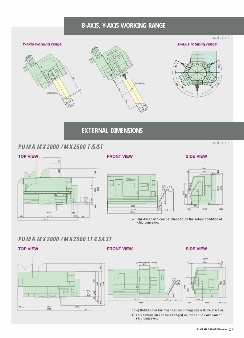
Y-axis working range B-axis rotating range
TOP VIEW FRONT VIEW SIDE VIEW
TOP VIEW FRONT VIEW SIDE VIEW
EXTERNAL DIMENSIONS
B-AXIS, Y-AXIS WORKING RANGE
PUMA MX2000 / MX2500 T/S/ST
PUMA MX2000 / MX2500 LT/LS/LST
Note) Dotted color line means 80 tools magazine with the machine.
* : This dimension can be changed on the set-up condition of chip conveyor.
* : This dimension can be changed on the set-up condition of chip conveyor.

MACHINE SPECIFICATIONS
18 DOOSAN Infracore Products
Max. turning diameter mm 540Max. turning length mm 1,020 [1,520]Bar working diameter mm 65 / 76X1/2-axis travel mm 555 / - 555 / 185 555 / - 555 / 185Y-axis travel mm 160 (±80)Z1/2-axis travel mm 1,095[1,595] /- 1,095[1,595] / 1,140[1,640] 1,095[1,595]/ - 1,095[1,595]/1,140[1,640]A-axis travel mm - 1,065[1,565]Spindle speed rpm 5,000 / 3,500Spindle nose ASA A2#6/A2#8Spindle bearing diameter(front) mm 110 / 130Spindle bore diameter mm 76 / 90Cs spindle index angle deg 360(0.001)Chuck size inch 8″/ 10″Quill dia./ travel mm 100 / 150 -Quill bore taper MT# MT#4 (Built-in dead) -Spindle speed rpm - 5,000 / 3,500Spindle nose ASA - A2#6 / A2#8Spindle bearing diameter(front) mm - 110 / 130Spindle bore diameter mm - 76 / 90Cs spindle index angle deg - 360(0.001)Chuck size inch - 8″/ 10″Milling spindle speed rpm 10,000B-axis indexing deg 240(±120), 0.001No. of tool station - BMT65P, 12st - BMT65P, 12stOD tool size mm - 25 - 25Boring bar diameter mm - 40 - 40Indexing time sec - 0.2 - 0.2Rotary tool spindle speed rpm - 4,000 - 4,000Rapid traverse(X/Z/Y/A-axis) m/min 24 / 24 / 16 / - 24 / 24 / 16 / 24Tool shank CAPTO-C6, KM63UT* HSK-A63*Tool storage capacity Cam 24 {Cam 40,80}Max. tool diameter mm 90Max. tool diameter without adjacent tools mm 120Max. tool length mm 300Max. tool weight kg 8Tool selection method Fixed addressTool change time(tool to tool) sec 1.5Left spindle motor kW 22/26Right spindle motor kW - 22/26Milling spindle motor(30 min) kW 15Rotary tool spindle motor(15 min) kW - 5.5 - 5.5 Servo motor kW X1:4, Z1:4, Y:3, B:1.6 X1:4, Z1:4, X2: 3, X1:4, Z1:4, Y:3, X1:4, Z1:4, X2: 3, Z2: 4,(X, Z, Y, B, A-axis) Z2: 4, Y:3, B:1.6 B:1.6, A:4 Y:3, B:1.6, A:4Coolant pump(Milling spindle/Lower turret) kW 2.2 2.2 / 0.9 2.2 2.2 / 0.9Electric power supply(Rated capacity) kVa 43.2 / 55.9 50 / 62.6 58.7 / 83.5 60.1 / 85.4Machine height mm 2,600Machine dimensions length mm 4,520[5,500]
width mm 2,300[2,565] Machine weight kg 11,500[13,500] 12,000[15,000] 12,000[15,000] 12,500[15,500]
Item PUMA MX2000/2500[L] PUMA MX2000/2500T[LT] PUMA MX2000/2500S[LS] PUMA MX2000/2500ST[LST]
Capacity
Travel
Left Spindle
Prog. Tail stock
Right Spindle
Milling Spindle
Tool post(Lower)
Feedrates
Power source
Machine size
AutomaticTool Changer
Motor
Note) * : This is standard selection instead of CAPTO-C6 tool shank, { } : option
Standard Feature■Absolute positioning coder■Air blast for chuck jaw cleaning■Coolant supply equipment■Foot switch■Front guard door inter lock
■Full enclosure chip and coolant shield■Hand tool kit
(including small tool for operations)■Hyd. chuck & actuating cylinder
■Hydraulic power unit■Levelling jack screw & plates■Lubrication equipment■Manuals■Safety precaution name plates
■Soft jaws (total)■Spindle oil cooling unit■Tail center (Programmable built-in dead)■Through Spindle coolant (Milling spindle)■Work light
Optional Feature■Air gun■Automatic door■Automatic door with safety device■Automatic power off■Automatic measuring system
(in process touch probe)■Bar feeder interface
■Bar puller■Chip conveyor■Chip bucket■Coolant blower■Dual chucking pressure■Hardened & ground jaws■Oil mist collector
■Oil skimmer ■Pressure switch for
chucking pressure check■Parts unloader and conveyor ■Signal tower (yellow, red, green)■Special chucks■Through the spindle coolant
(Left or Right spindle)
■Tool monitoring system■Tool pre-setter (hydraulic type)■Linear scale (X1/Y/Z1-axis)■Minimum Quantity Lubrication
(MQL)system■Controller : Fanuc 16i-TB
(To fulfill simultaneous control of 5 axes)
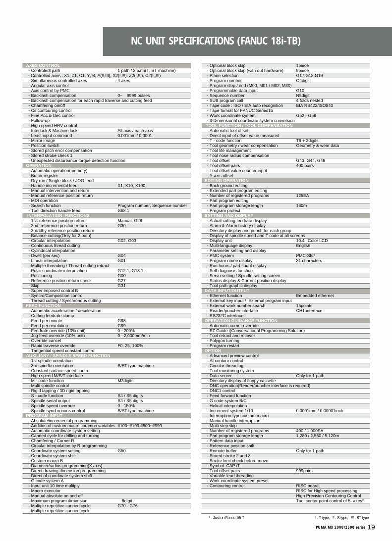
NC UNIT SPECIFICATIONS (FANUC 18i-TB)
PUMA MX 2000/2500 series 19
! : T type, !! : S type, !!! : ST type* : Just on Fanuc 16i-T
- Optional block skip 1piece- Optional block skip (with out hardware) 9piece- Plane selection G17,G18,G19- Program number O4digit- Program stop / end (M00, M01 / M02, M30)- Programmable data input G10- Sequence number N5digit- SUB program call 4 folds nested- Tape code : ISO / EIA auto recognition EIA RS422/ISO840- Tape format for FANUC Series15- Work coordinate system G52 - G59- 3-Dimensional coordinate system conversionTOOL FUNCTION / TOOL COMPENSATION- Automatic tool offset- Direct input of offset value measured - T - code function T6 + 2digits- Tool geometry / wear compensation Geometry & wear data- Tool life management- Tool nose radius compensation- Tool offset G43, G44, G49- Tool offset pairs 400 pairs - Tool offset value counter input- Y-axis offset
EDITING OPERATION- Back ground editing- Extended part program editing- Number of registered programs 125EA- Part program editing- Part program storage length 160m- Program protect
SETTING AND DISPLAY- Actual cutting feedrate display- Alarm & Alarm history display- Directory display and punch for each group- Display of spindle speed and T code at all screens- Display unit 10.4″Color LCD- Multi-language display English- Parameter setting and display- PMC system PMC-SB7- Program name display 31 characters- Run hours / part count display- Self-diagnosis function- Servo setting / Spindle setting screen- Status display & Current position display- Tool path graphic display
DATA INPUT/OUTPUT- Ethernet function Embedded ethernet- External key input / External program input- External work number search 15points- Reader/puncher interface CH1.interface- RS232C interface
OPERATION GUIDANCE FUNCTION - Automatic corner override- EZ Guide i(Conversational Programming Solution)- Tool retract and recover- Polygon turning- Program restart
OPTION- Advanced preview control- AI contour control- Circular threading- Tool monitoring system- Data server Only for 1 path- Directory display of floppy cassette- DNC operation(Reader/puncher interface is required)- DNC1 control- Feed forward function- G code system B/C- Helical interpolation- Increment system 1/10 0.0001mm / 0.00001inch- Interruption type custom macro - Manual handle interruption - Multi step skip - Number of registered programs 400 / 1,000EA- Part program storage length 1,280 / 2,560 / 5,120m- Pattern data input- Reference position shift- Remote buffer Only for 1 path- Stored stroke 2 and 3- Stroke limit check before move- Symbol CAP iT- Tool offset pairs 999pairs- Variable lead threading- Work coordinate system preset- Contouring control RISC board,
RISC for High speed processingHigh Precision Contouring ControlTool center point control of 5- axes*
AXES CONTROL- Controledl path 1 path / 2 path(T, ST machine)- Controlled axes : X1, Z1, C1, Y, B, A(!!,III), X2(!,!!!), Z2(!,!!!), C2(!!,!!!)- Simultaneous controlled axes 4 axes- Angular axis control - Axis control by PMC- Backlash compensation 0~±9999 pulses- Backlash compensation for each rapid traverse and cutting feed- Chamfering on/off- Cs contouring control- Fine Acc & Dec control- Follow-up- High speed HRV control- Interlock & Machine lock All axis / each axis- Least input command 0.001mm / 0.0001″- Mirror image- Position switch- Stored pitch error compensation- Stored stroke check 1- Unexpected disturbance torque detection function
OPERATION- Automatic operation(memory)- Buffer register- Dry run / Single block / JOG feed- Handle incremental feed X1, X10, X100- Manual intervention and return- Manual reference position return- MDI operation- Search function Program number, Sequence number- Tool direction handle feed G68.1
INTERPOLATION FUNCTIONS- 1st. reference position return Manual, G28- 2nd. reference position return G30- 3rd/4thy reference position return- Balance cutting(Only for 2 path)- Circular interpolation G02, G03- Continuous thread cutting- Cylindrical interpolation- Dwell (per sec) G04- Linear interpolation G01- Multiple threading / Thread cutting retract- Polar coordinate interpolation G12.1, G13.1- Positioning G00- Reference position return check G27- Skip G31- Super imposed control B- Syncro/Composition control- Thread cutting / Synchronous cutting
FEED FUNCTION- Automatic acceleration / deceleration- Cutting feedrate clamp- Feed per minute G98- Feed per revolution G99- Feedrate override (10% unit) 0 - 200%- Jog feed override (10% unit) 0 - 2,000mm/min- Override cancel- Rapid traverse override F0, 25, 100%- Tangential speed constant control
AUXILIARY / SPINDLE SPEED FUNCTION- 1st spindle orientation- 3rd spindle orientation S/ST type machine- Constant surface speed control- High speed M/S/T interface- M - code function M3digits- Multi spindle control- Rigid tapping / 3D rigid tapping- S - code function S4 / S5 digits- Spindle serial output S4 / S5 digits- Spindle speed override 0 - 150%- Spindle synchronous control S/ST type machine
PROGRAM INPUT- Absolute/incremental programming- Addition of custom macro common variables #100~#199,#500~#999- Automatic coordinate system setting- Canned cycle for drilling and turning- Chamfering / Corner R- Circular interpolation by R programming- Coordinate system setting G50- Coordinate system shift- Custom macro B- Diameter/radius programming(X axis)- Direct drawing dimension programming- Direct of coordinate system shift- G code system A- Input unit 10 time multiply- Macro executor- Manual absolute on and off- Maximum program dimension ±8digit- Multiple repetitive canned cycle G70 - G76- Multiple repetitive canned cycle Ⅱ

AUSTRIAVienna
BELGIUMGullegem
BULGARIASofia
CZECHBrno
DENMARKRanders
FINLANDTampere
FRANCEAnnecy
GERMANYDusseldorf
GREECEAthens
HUNGARYBudapest
ITALYParma
NETHERLANDSGoorn
NORWAYOslo
POLANDKrakow
PORTUGALLisbon
ROMANIABucharest
RUSSIAMoscow
SLOVENIALjubljana
SPAINBarcelona
SWEDENStockholm
SWITZERLANDZurich
TURKEYIstanbul
U. K.Leamington
SOUTH AFRICAKempton Park
AUSTRALIAMelbourneSydney
NEW ZEALANDAuckland
INDIAPune Bangalore
INDONESIAJakarta
ISRAELHerzlia
MALAYSIAPuchong
PAKISTANIslamabad
SINGAPORESingapore
THAILANDBangkok
U.A.ESharjah
VIETNAMHanoi
EGYPTCairo
CHINABeijingShanghaiShenyangGuangzhouChongqing
HONG KONGKowloon
ARGENTINARosario
BRAZILSampaio
CANADAMontrealTorontoVancouverEdmonton
CHILESantiago
COLOMBIABogota
MEXICOGuadalajara Mexico City Monterrey Vera Cruz
U.S.A.Atlanta Birmingham Charlotte Chicago Cincinnati Cleveland Dallas Denver Detroit Houston
Indianapolis Kansas City Little Rock Los Angeles Milwaukee MinneapolisNew Orleans Norfolk Philadelphia Phoenix Pittsburgh Portland Rochester Salt Lake City San Diego San Francisco Seattle Springfield St. Louis Tampa Trenton Tulsa
VENEZUELACarabobo
EU0505SPi-ser
Design and specifications are subject to change without prior notice.
Head Office : Doosan Tower 23rd FL., 18-12, Euljiro-6Ga, Jung-Gu, Seoul, Korea 100-730Tel : ++82-2-3398-8651 Fax : ++82-2-3398-8699 E-mail:[email protected] Infracore America Corp.: 8 York Avenue, West Caldwell, NJ 07006, U.S.A.Tel: ++1-973-618-2500 Fax: ++1-973-618-2501Doosan Infracore Germany GmbH : Hans-Böckler-Strasse 29, D-40764 Langenfeld-Fuhkamp, Germany.Tel: ++49-2173-8509-10 Fax: ++49-2173-8509-60China Representative Office: Room 207 Zhongchen Office Building No.1 Li Ze Zhong 2 Lu Wangjing Chaoyang District, Beijing P.R.China Tel: ++86-10-6439-0500 (EXT.101) Fax: ++86-10-6439-1086