
Domain & Model Driven Geographic Database Designjugurta/papers/DE book.pdf · Domain & Model Driven...
25
Domain & Model Driven Geographic Database Design Jugurta Lisboa-Filho, Filipe Ribeiro Nalon, Douglas Alves Peixoto, Gustavo Breder Sampaio and Karla Albuquerque de Vasconcelos Borges Abstract After many years of research in the field of conceptual modeling of ge- ographic databases for Geographic Information Systems, experts have produced many different alternatives of conceptual data models from extensions of the Entity- Relationship model or of Unified Modeling Language (UML). However, the lack of consensus on which is the most suitable one for modeling applications in the geo- graphical domain, brings up a number of problems for field advancement, mainly problems of interoperability of database design and CASE tools. The Model Driven Architecture (MDA) approach allows the development of systems from an abstract view until the corresponding implementation code that can be automatized by means of models transformation. A UML Profile is an extension mechanism of UML which allows a structured and precise extension of its constructors, being a good solution to standardize domain-specific modeling, as it uses the entire UML infrastructure. This chapter describes the use of MDA approach in the design of databases in geo- graphical domain; using a UML Profile called GeoProfile aligned with international standards of ISO 191xx series. The chapter also shows that with the automatic trans- formation of models it is possible to achieve the generation of scripts for spatial databases from a conceptual data schema in a high level of abstraction. Jugurta Lisboa-Filho Universidade Federal de Vic ¸osa, Departamento de Inform´ atica, e-mail: [email protected] Filipe Ribeiro Nalon Prodabel - Empresa de Inform´ atica e Informac ¸˜ ao do Munic´ ıpio de Belo Horizonte e-mail: [email protected] Douglas Alves Peixoto Universidade Federal de Vic ¸osa, Departamento de Inform´ atica e-mail: dou- [email protected] Gustavo Breder Sampaio Universidade Federal de Vic ¸osa, Departamento de Inform´ atica e-mail: [email protected] Karla Albuquerque de Vasconcelos Borges Prodabel - Empresa de Inform´ atica e Informac ¸˜ ao do Munic´ ıpio de Belo Horizonte e-mail: [email protected] 1
Transcript of Domain & Model Driven Geographic Database Designjugurta/papers/DE book.pdf · Domain & Model Driven...
Domain & Model Driven Geographic DatabaseDesign
Jugurta Lisboa-Filho, Filipe Ribeiro Nalon, Douglas Alves Peixoto, GustavoBreder Sampaio and Karla Albuquerque de Vasconcelos Borges
Abstract After many years of research in the field of conceptual modeling of ge-ographic databases for Geographic Information Systems, experts have producedmany different alternatives of conceptual data models from extensions of the Entity-Relationship model or of Unified Modeling Language (UML). However, the lack ofconsensus on which is the most suitable one for modeling applications in the geo-graphical domain, brings up a number of problems for field advancement, mainlyproblems of interoperability of database design and CASE tools. The Model DrivenArchitecture (MDA) approach allows the development of systems from an abstractview until the corresponding implementation code that can be automatized by meansof models transformation. A UML Profile is an extension mechanism of UML whichallows a structured and precise extension of its constructors, being a good solutionto standardize domain-specific modeling, as it uses the entire UML infrastructure.This chapter describes the use of MDA approach in the design of databases in geo-graphical domain; using a UML Profile called GeoProfile aligned with internationalstandards of ISO 191xx series. The chapter also shows that with the automatic trans-formation of models it is possible to achieve the generation of scripts for spatialdatabases from a conceptual data schema in a high level of abstraction.
Jugurta Lisboa-FilhoUniversidade Federal de Vicosa, Departamento de Informatica, e-mail: [email protected]
Filipe Ribeiro NalonProdabel - Empresa de Informatica e Informacao do Municıpio de Belo Horizonte e-mail:[email protected]
Douglas Alves PeixotoUniversidade Federal de Vicosa, Departamento de Informatica e-mail: [email protected]
Gustavo Breder SampaioUniversidade Federal de Vicosa, Departamento de Informatica e-mail: [email protected]
Karla Albuquerque de Vasconcelos BorgesProdabel - Empresa de Informatica e Informacao do Municıpio de Belo Horizonte e-mail:[email protected]
1

2 Lisboa-Filho, J., Nalon,F.R., Peixoto,D.A., Sampaio,G.B., Borges,K.A.V.
Key words: UML Profile; Model Driven Architecture; Geographic Database; Con-ceptual Data Modeling
1 Introduction
The activity of software development is a task that requires increasing use of stan-dardized methodologies and techniques that are widely known. Currently, the mainconcern of the designer is a good understanding of the problem domain in order togenerate solutions that suit the real necessities of the users.
In order to assist in this task of understanding the problem and reducing the sys-tem complexity to be developed, the main technique that is used is modeling. Amodel is a reality simplification [9]. In database design, the construction of mod-els in steps helps to design the database structure without having to worry aboutimplementation details.
In the last 20 years, research has aimed to create or adapt conceptual data modelsfor geographic applications. The existence of several models has brought a prob-lem to the area, which is the lack of a modeling standard. Tools have been createdfor different models and it is difficult to obtain interoperability among the createdsolutions.
For the standardization of these models, a UML profile called GeoProfile [21]was proposed. A profile is an extension mechanism of the Unified Modeling Lan-guage (UML) , which allows customizing the UML to a specific domain. The Geo-Profile was proposed for conceptual data modeling in the geographic domain, whichputs together the characteristics of the main existing spatial data conceptual mod-els. The construction process of the GeoProfile can be compared with a step of thedomain engineering, which is the domain analysis, in which the domain knowledgeis studied and analyzed. According to Falbo et. al [10], one of the domain analysisgoals is to make possible the reuse of the domain model generated for a group of ap-plications. One of the UML profile construction outcomes is a domain metamodel.This metamodel contains reusable requirements, of the intended domain, to buildapplications in that domain.
Furthermore, as an effort for the geographic information standardization, someorganizations, such as the International Organization for Standardization (ISO) andthe Open Geospatial Consortium (OGC), have published international standards tohelp in the construction of standardized geographic applications.
The objective of this chapter is to describe the use of the Model Driven Archi-tecture (MDA) approach in the design of databases in geographical domain, usingthe GeoProfile aligned with international standards of ISO 191xx series. The chapteralso shows that with the automatic transformation of models it is possible to achievethe generation of scripts for spatial databases from a conceptual data schema in ahigh level of abstraction.
Section 2 presents the main concepts related to modeling of geographic databases,describes the main international standards for geographic information and summa-

Domain & Model Driven Geographic Database Design 3
rizes the GeoProfile. Section 3 describes the steps and types of models used in theMDA approach. Section 4 describes the process of designing geographic databasesbased on the MDA approach. Section 5 illustrates the entire process of designinga geographic database, based on a case study of a system in the field of sugarcanecrop for ethanol production. Some conclusions are presented in Section 6.
2 Geographic Database Modeling
2.1 Basic Requirements
One of the main components of a Geographic Information System (GIS) is the stor-age component denominated geographic database , whose function is to structureand store the data in order to allow analysis operations involving spatial and al-phanumeric data [36].
Due to the complexity of GIS applications, a major challenge in developing thesesystems has been designing the database, since this type of project requires the useof different tools, as the activities required for their preparation vary according to thecomplexity of the system, the type of personnel involved, the database managementsystem (DBMS) used, etc.
The database design is traditionally done in three stages: conceptual, logical andphysical [8]. According to Borges et al. [4], for applications in the geographicaldomain, the level of conceptual representation provides a set of concepts with whichthe geographic phenomena, such as rivers, buildings, roads and vegetation, can bemodeled at a high level of abstraction, as perceived by the user. Classes to be createdin the database are defined at this level, which are possibly associated with somekind of spatial representation.
Parent et al. [27] highlight some advantages of using conceptual modeling inapplications that manipulate geospatial data. First, users can express their knowl-edge of the system using concepts that are close to their reality and independentof computing concepts. Moreover, as conceptual modeling is independent of sys-tem implementation, the result of modeling remains valid in case of technologicalchanges. That is, the developed scheme can be reused regardless of the GIS chosenfor the system implementation. Finally, due to its readability, conceptual modelingpromotes the exchange of semantic information referring to the project.
Because of the particularities of the geographic information, several specific so-lutions for the modeling of geographic data have emerged in recent years. Lisboa-Filho and Iochpe [19] proposed a list of key requirements for modeling geographicdata as follows:
• Geographic phenomena and conventional objects: In a geographic database, inaddition to the data on geospatial phenomena, there are generally conventionaldata, such as those contained in any information system. A farm, for example, canbe a geographical phenomenon if its spatial information is stored in the database,
4 Lisboa-Filho, J., Nalon,F.R., Peixoto,D.A., Sampaio,G.B., Borges,K.A.V.
such as its boundaries. On the other hand, the information about the owner ofthe farm can be an example of a conventional object if it does not present spatialfeatures;
• Field and object views: The classification of geographic phenomena in these twoviews is intended to represent properly the geographical reality observed. Whilein the object view the real world consists of entities and individual well-definedspatial boundaries (e.g., rivers, plots, and streets), in the field view, the real worldis understood as a set of attributes that vary continuously in space (e.g., relief,soil type, temperature);
• Spatial Aspects: This requirement refers to the need of connecting fields and ge-ographic objects to an abstract spatial form for their representation. In the objectview the phenomena are represented by points, lines, polygons, or their combi-nations. In the field view, a continuous surface can be represented by numericalmodels, sets of isolines or grid of cells, for example. The type of representationto be used depends on the purpose of the application, the representation scale andthe shape of the phenomenon;
• Thematic aspects: In a GIS, geographic entities are not treated in isolation. Theyare grouped according to the characteristics and relationships they have in com-mon. The division of a system by themes (e.g., hydrography, vegetation, urbanplanning) allows modeling simplification and facilitates understanding of thearea by the designer;
• Multiple representations: Users can have different views of the same phenomenon,which are probably represented in different scales or projections. For example, acity can be represented as a point or a polygon depending of the data scale;
• Spatial relationships: The identification of the types of relationships that must bekept in the database is a complex problem, since the number of possible rela-tionships is large in the geographical area, because of the spatial interactions thatmay occur among the phenomena. For example, a road can cross a river, but thisrelationship can be or not be held in the database;
• Temporal aspects: The storage of the changes that occur in geographic features isimportant for a better understanding of the phenomena and making predictions.For example, the limits of a parcel can change over the years.
Other similar classifications were also proposed, for example, Friis-Christensenet al. [11] divide the requirements for modeling geographic data into five groups asfollows: spatial-temporal properties, roles, associations, constraints and data quality.In a deeper analysis, it is possible to confirm that both classifications are equivalentin many aspects.
Pinet [28] lists a series of conceptual models of specific data for the geographi-cal domain. Among them we can highlight some models based on objects, such asGeoOOA [17], OMT-G [4], MADS [27], UML-GeoFrame [20] and the PVL modelof the Perceptory tool [1]. Each model has particular characteristics and seeks tomeet the requirements for geographic application modeling. Based on these modelsand according with International Standards for Geographic Information shown inthe next section, the UML GeoProfile was proposed as described in the Section 2.3.

Domain & Model Driven Geographic Database Design 5
2.2 International Standards for Geographic Information
Standards are used in many fields of society and some of them are better known as,for example, the series of standards ISO 9000, which is quite common in organiza-tions, because it defines a set of rules and guidelines for quality management in anorganization. With respect to geographic information, some efforts to standardizework have been undertaken by organizations like the International Organization forStandardization (ISO) and the Open Geospatial Consortium (OGC).
These organizations are examples of the two types of groups that exist for inter-national standardization, which are the international organizations and internationalconsortia. International organizations base their decisions on consensus and are in-dependent of the interests of individual industries or governments. Their standardsare known as de jure standards. An example of international organization is theISO. On the other hand, the international consortia are made up primarily of mem-bers from industry, government agencies and universities. The standards developedby consortia are called industry standards or de facto standards. The OGC can beconsidered the most important consortium in the geographic information commu-nity [18]. According to Brodeur and Badard [5], the development of standards forgeographic information aims to reduce the inconsistency between de jure and defacto standards.
2.2.1 The ISO 191xx series of the ISO/TC 211 Technical Committee
The Technical Committee ISO/TC 211 is the one responsible for the preparation ofthe ISO 191xx series, which defines the international standards regarding the geo-graphic information field. These standards aim to promote the usage of geographicinformation in an efficient, effective and economical way, thus contributing to thesolution of global problems, such as the humanitarian and ecological problems [35].
The ISO 191xx series standards are divided into specific groups. As listed in theISO/TC 211 [35], there is the group of standards that specify the infrastructure forthe geospatial standardization, standards that describes data models for geographicinformation, standards for geographic information management, standards for geo-graphic information services, standards for encoding of geographic information andstandards for specific thematic areas. These standards can contribute in several lev-els of abstraction, since modeling up to the consideration of implementation aspects.In this chapter some standards related to data models for geographic information,more specifically the ISO 19107 Spatial Schema [33], ISO 19108 Temporal Schema[32] and ISO 19123 Schema for Coverage Geometry and Functions [34] standards,are analyzed.
The ISO 19107 Spatial Schema standard specifies a schema to describe and ma-nipulate the spatial characteristics of the geographic features. A feature is an ab-straction of a real world phenomenon. This abstraction is a geographic feature if itis associated to a relative localization on the Earth [33]. The standard consists ofclasses’ diagrams that can be used in application schema, profiles and implementa-
6 Lisboa-Filho, J., Nalon,F.R., Peixoto,D.A., Sampaio,G.B., Borges,K.A.V.
tion specifications. It also defines spatial operations, standards for use in the access,query, management, processing, and data exchange of geographic objects. The ISO19107 standard defines in details the geometric and topological characteristics thatare necessary to describe the geographic features.
The ISO 19108 Temporal Schema standard defines the concepts regarding thetemporal characteristics of geographic information, showing how these characteris-tics are abstracted from the real world. Jensen [14] considers two types of time: thevalid time and the transaction time. The first one is the time when a fact is true inthe observed reality and it is generated by the user. The second one is the time whena fact is stored in a database and it can be recovered. This international standardemphasizes the valid time instead of the transaction time. The standard consists of aclass hierarchy that considers the geometric and topological aspects of the temporalcharacteristics [32].
The ISO 19123 Schema for Coverage Geometry and Function standard, on theother hand, defines a schema for the spatial characteristics of coverage. Coverageis a feature that has multiple values for each type of attribute and can representa simple feature or a set of features. They integrate discrete and continuous geo-graphic phenomena [34]. Examples of coverage include raster, TIN, point coverageand polygon coverage. They are used in several specific areas such as, for instance,remote sensing, meteorology, soils and vegetation.
Some related works have analyzed conceptual data models and their integrationwith geographical standards. Belussi et al. [3] describe the conceptual data modelGEOUML in which a geographic database schema can be designed from the special-ization of ISO TC211 standards. However, this model does not use graphic symbolsfor representing phenomena’s spatial representation, which is a feature presented invarious models proposed in the literature [1]. A study where the model elements ofthe Perceptory tool are related to the ISO standards is presented in [6].
2.2.2 Open Geospatial Consortium Standards
The Open Geospatial Consortium (OGC) is currently the main consortium respon-sible for developing industry standards for Geographic Information Systems. Its de-velopment process is different from the ISO approach. The OGC develops specifi-cations mainly focused on implementation, while ISO develops more abstract spec-ifications.
Despite these minor differences, both ISO and OGC have developed cooperativeagreements to harmonize their work and to develop future work [6]. For example,the document OpenGIS - Simple Feature Access is also recognized by the ISO underthe name ISO 19125. The document is divided into two parts. The first (CommonArchitecture) describes a common architecture for simple geographical features andthe second part (SQL option) describes an SQL implementation of the model de-scribed in the first part. Both parts deal with simple features, namely features whosegeometry is restricted to two dimensions. The OGC standard used is the Simple

Domain & Model Driven Geographic Database Design 7
Feature Access, as well as GeoProfile and projects using the MDA approach, bothdescribed in this chapter; this will be handled as its corresponding ISO 19125.
2.3 GeoProfile - a UML Profile for GIS Databases
The Unified Modeling Language (UML) is a visual modeling language used for doc-umenting artifacts of software systems. Despite of being a general purpose languagethat can be used in various application domains, there are situations in which the el-ements of the UML are not able to effectively express some concepts of particulardomains. Thus, the language provides extension mechanisms that allow customizingit to suit a specific application domain as follows:
• Stereotypes: A stereotype defines how an existing metaclass may be extended andenables the use of specific terminology for a domain or different platform in placeof or in addition to the terminology used for the extended metaclass. Stereotypescan also change the appearance of the elements of the extended model usinggraphic icons;
• Tagged values: They are additional meta-attributes associated with a metaclassof the metamodel extended by a profile and add information to elements of themodel;
• Constraints: These are restrictions associated with the corresponding elements ofthe metamodel. They can be written using natural languages or in Object Con-straint Language (OCL), which is also standardized by the Object ManagementGroup (OMG);
• Profile: A UML profile is a set of extension mechanisms grouped in an UMLpackage stereotyped as profile.
A well-specified UML profile will have direct support of Computer Aided Soft-ware Engineering (CASE) tools. In other words, once the profile is defined, thereis no need to implement new CASE tools. Enterprise Architect [31] and RationalSoftware Modeler [13] are examples of CASE tools with support for UML profiles.
The UML profile denominated GeoProfile [21, 23] was proposed to integrate thefeatures of the major geographic data conceptual models. Thus, the GeoProfile is nota new model, but rather a compilation and integration from the builders of specificGIS applications present in the main models in the literature. With this, it is possibleto use all the elements and advantages of UML 2.0. In addition, a designer famil-iarized with a particular model can customize GeoProfile, making it look like thatmodel. The GeoProfile comprises a metamodel and a set of stereotypes, describedin the following subsections.

8 Lisboa-Filho, J., Nalon,F.R., Peixoto,D.A., Sampaio,G.B., Borges,K.A.V.
2.3.1 The GeoProfile Metamodel
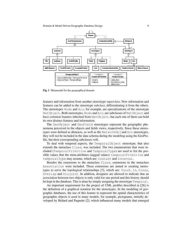
The GeoProfile metamodel, as defined in [21], is showed in Fig. 1. A geographicdatabase comprises a number of themes, each of presented as a Theme metaclass.A theme can be formed by the aggregation of other themes or objects with orwithout spatial representation, characterized by the classes GeoPhenomenon andConventionalObj, respectively.
When one chooses to associate a spatial representation with objects of a class, it ispossible that the phenomenon is perceived in the geographic field view (GeoField)or object view (GeoObject). Depending on the technique used in geographicinformation acquisition in the field, its representation is selected from six op-tions as described in [12]: AdjPolygons, Isolines, TIN, GridOfPoints,GridOfCells or IrregularPoints. Representation of geographic objectscan be of the types Point, Line, Polygon or ComplexSpatialObj (the ob-ject geometry consists of other geometries). To specify multiple representations, it ispossible to use more than one stereotype in the same class of the conceptual schema.
The metaclass Network is used to modeling a whole network structure andcontains only alphanumeric attributes which describes the general features of thenetwork. Since this metaclass does not have spatial information, it was defined as aspecialization of ConventionalObj. The networks are formed by NetObjectobjects, which can be nodes (Node), unidirectional arcs (Unidirectional) orbidirectional arcs (Bidirectional).
GeoProfile also indicates whether a class is considered temporary or not. In thiscase, it is implied that both the attributes and spatial data of an object can vary,and these changes must be maintained in the database. In this way, the metaclassTemporalObjectwas added to the metamodel. This metaclass has two attributesthat characterize temporal information. One of these attributes indicates the tem-poral type (validity time, transaction time or bitemporal time), whereas the otherdefines the used temporal primitive type (instant or interval). There are two enu-merations (TemporalType and TemporalPrimitive) for the possible valuesthese attributes can assume.
2.3.2 GeoProfile‘s stereotypes
After creating the domain metamodel, the next step is to extend the UML meta-classes to create the profile itself. Fig. 2 illustrates the stereotypes that have beendefined for GeoProfile, which extend the metaclasses Class and Associationof the UML. The black arrows refer to an extension relation between a stereotypeand an UML element. This is the mechanism proposed by OMG to extend the UMLin the following way: a basic UML element can be used to represent an element ofa generic domain; in this case the UML elements Class and Relationship areused to represent the GeoProfile elements.
The white arrows refer to a specialization relation between UML stereotypes.This kind of relation is called Is A, where a stereotype subclass inherits all the
Domain & Model Driven Geographic Database Design 9
Fig. 1 Metamodel for the geographical domain
features and information from another stereotype superclass. New information andfeatures can be added to the stereotype subclass, differentiating it from the others.The stereotypes Node and Arc, for example, are specializations of the stereotypeNetObject. Both stereotypes, Node and Arc, are subclasses of NetObject andhave common features inherited from NetObject, but each one of them can holdits own distinct features and information.
The GeoObject and GeoField stereotypes represent the geographic phe-nomena perceived in the objects and fields views, respectively. Since these stereo-types were defined as abstracts, as well as the NetworkObj and Arc stereotypes,they will not be included in the data schema during the modeling using the GeoPro-file, but their corresponding subclasses will.
To deal with temporal aspects, the TemporalObject stereotype, that alsoextends the metaclass Class, was included. The two enumerations that were in-cluded (TemporalPrimitive and TemporalType) are used to list the pos-sible values that the meta-attributes (tagged values) temporalPrimitive andtemporalType may assume, which are: instant and interval.
Besides the extensions to the metaclass Class, extensions to the metaclassAssociation were included. These extensions are aimed to creating stereo-types to serve the topological relationships [7], which are: Touch, In, Cross,Overlap and Disjoint. In addition, designers are allowed to indicate that anassociation between two objects is only valid for one period and this history shouldbe kept in the database. This is done by simply assigning the stereotype Temporal.
An important requirement for the project of UML profiles described in [26] isthe definition of a graphical notation for the stereotypes. In the modeling of geo-graphic databases, the use of this feature to represent the spatial characteristics ofgeographic objects is used in many models, for example, pictograms, initially de-veloped by Bedard and Paquette [2], which influenced many models that emerged

10 Lisboa-Filho, J., Nalon,F.R., Peixoto,D.A., Sampaio,G.B., Borges,K.A.V.
Fig. 2 GeoProfile’s Stereotypes
later. They help improve clarity and make the modeling more intuitive for the de-signer and easily understood by users. Fig. 3 shows a set of icons that can be addedto GeoProfile stereotypes. These icons were also based on the models mentionedabove (UML-GeoFrame, OMT-G, MADS, and GeoOOA Perceptory’s model), butdesigners accustomed to using a particular model can customize these icons as theywish.
Fig. 3 Graphical notation for stereotypes
Figures 4 and 5 illustrate some examples of classes modeled with GeoProfilestereotypes in graphic and textual forms. Fig. 4 illustrates an example of spa-tial relationship between two classes (District and AdmRegion) with poly-gon spatial representations, specified by the stereotype Polygon. The stereotypeOverlap shows the spatial relationship that occurs between the classes. Fig. 5illustrates three examples of classes with spatial representation in the field view.

Domain & Model Driven Geographic Database Design 11
The SatImage class with the stereotype GridOfCells, the Humidity classwith the stereotype IrregularPoints and the Relief class with the stereo-type GridOfPoints.
Fig. 4 An example of a conceptual schema using GeoProfile
Fig. 5 Examples of classes using stereotypes for the field view
Besides the stereotypes, some constraints were also added, which are useful forthe conceptual schema validation. Those constraints basically prevent the occur-rence of three error types: addition of incompatible stereotypes with a same element,poor network construction and addition of impossible topological relationships be-tween two elements (e.g. Cross relationship between two geographic objects withpoint representation). These three constraints groups were analyzed and a set ofOCL expressions was specified. OCL has been frequently used to specify additionalintegrity constraints to the UML diagrams [29].
The code below shows one of the GeProfile’s OCL constraints, which is ap-plied to the stereotype GeoField. This constraint defines that each class stereo-typed as a geofield (context GeoField) must capture all stereotypes appliedto this class (getAppliedStereotypes). If the output is stereotyped as a geo-graphic object (Point, Line, Polygon, or ComplexSpatialObj) throughthe method select, the result set must be empty (isEmpty). This constraintchecks for incompatible stereotypes in a class which has been assigned the stereo-type GeoField in the schema. More details regarding all OCL constraints and howto implement them in a UML profile can be accessed in the GeoProfile’s Web pageat www.dpi.ufv.br/projetos/geoprofile.
context GeoFieldinv: self.getAppliedStereotypes() ->

12 Lisboa-Filho, J., Nalon,F.R., Peixoto,D.A., Sampaio,G.B., Borges,K.A.V.
select(s | s.name = ’Point’ or s.name = ’Line’ ors.name = ’Polygon’ or s.name = ’ComplexSpatialObj’)-> isEmpty()
Finally, although the GeoProfile is most commonly used to static data schemadesigns, the class behavioral modeling, that is, the specification of the applicableoperations to instances of a class, can be done naturally within this class, usingmethods specified in the UML.
3 Model-Driven Architecture
To improve software development OMG has adopted the MDA approach, whichemphasizes the use of models. In this approach, the software development processis directed by the modeling activity of the system. A system model is a descriptionusing a specific notation. The artifacts produced in MDA are formal models, that is,models that can be understood by computers [25].
In MDA, the system requirements are modeled using a Computation IndependentModel (CIM). This model is called domain model or business model and it uses afamiliar vocabulary to the domain experts. A CIM does not show details of thesystems structure, but of the environment in which the system will operate. Thiskind of model provides a useful way to understand the problem itself [9, 25].
In the second level of abstraction we find the Platform Independent Model (PIM).This is a model with an abstraction level relatively high and independent from anyimplementation technology [9, 16, 25].
Later, the PIM is transformed into a Platform Specific Model (PSM). A PSMis customized in order to specify the system in terms of implementation construc-tors which are available in a specific implementation technology. For instance, aPSM relational database include terms such as table, column, foreign key,among others. A PIM can be transformed into one or more PSMs. For each spe-cific technology platform, a separate PSM is generated. The following step is thetransformation of each PSM to source code. This transformation is relatively directsince the PSM is adjusted to the selected technology. Fig. 6 illustrates the differentlevels of abstraction of MDA approach, showing the CIM as the highest level ofabstraction model and the others, PIM and PSM, as inferior levels.
The CIM, PIM and PSM are shown as artifacts in different steps in the systemdevelopment life cycle, and they represent different abstraction levels in its specifi-cation as well. The ability of transforming a high level CIM into a PIM and later,transforming a PIM into a PSM increases the abstraction level in which a designercan work. This allows a designer to face more complex systems with fewer struggles[9, 25].
The development process using MDA approach may be compared with the pro-cess of domain engineering, which highlights three main steps: domain analysis,

Domain & Model Driven Geographic Database Design 13
domain design, and domain implementation [10]. At the domain analysis step, thedomain requirements are defined. These requirements are expected to be reusable,such as the CIM in the MDA approach, which is used to understand the problemitself. In the domain design step a generic and independent of platform architectureis established, such as the PIM level. Finally, at the domain implementation stepthe identification of reusable assets is done, as well as the architecture and compo-nents implementation, such as in the PSM level of the MDA, which transforms theconsidered PIM into a specific platform.
One of the aims of the MDA approach is to reduce the system development time.For this purpose, models in different abstraction levels are used, starting with modelsin high abstraction levels. Therefore, one of the challenges is transform high levelmodels into lower level models. The transformation of models is the process ofconverting a model into another model that represent the same system [25].
Fig. 6 Levels of abstractionof the MDA approach
An important characteristic of the MDA is that the transformations are auto-matically executed. Traditionally, the transformations from model to model or frommodel to code are manual. In the MDA approach, on the other hand, transformationsare executed preferably by tools [16].
An automatic mapping is specified using a language to describe the transforma-tion of a model into another. A desirable quality of a transformation language isportability; this enables the use of a mapping with different tools [25].
Some tools, available in the market, for supporting the MDA approach, havemechanisms for transforming predefined templates, but the ideal is to offer sup-port to a language that enables users to customize the transformation of models asneeded. An example of such language is the Atlas Transformation Language (ATL)developed by the research group ATLAS INRIA & LINA [24].
This language allows the definition of transformation rules, in which, given aschema created in a model of entry, along with transformation rules, generates a newschema in the output model, according to those rules. Thus, this language allowsthe transformation of a schema made from GeoProfile, for example, into another
14 Lisboa-Filho, J., Nalon,F.R., Peixoto,D.A., Sampaio,G.B., Borges,K.A.V.
specific conceptual model, allowing the exchange of information between modelsand giving the designer flexibility in creating a schema. This approach can also beused in the transformation of a schema in each of the three levels of MDA; in thiscase, using the ATL language, it is necessary to define the transformation rules foreach level.
4 Modeling Geographic Databases using MDA
The use of MDA is not specific to the geographical domain, but it was used in thiswork to exemplify a domain engineering on the geographical field of study.
The development of GeoProfile was mainly motivated by the fact that UML canbe used, along with all its available resources, for example, CASE tools, to model ageographic database.
The development of GeoProfile based on international standards is in accordancewith the abstraction levels of the MDA approach. A major benefit of this approachis the productivity gain through the emphasis on modeling and the transformationof high-level models to lower-level models in an automated way [16]. Thus, thedesign of geographic databases can also take advantage of these benefits. For exam-ple, using tools that support the transformations will make it possible to generate,from the GeoProfile, lower-level models and, later, the database scripts for specifictechnologies, such as Oracle Spatial and PostGIS.
In related studies, Miralles and Libourel [22] propose a framework to designand implement spatial-temporal databases following the MDA approach, but thisframework does not consider the CIM level, but suggests the use of the Perceptorytool to specify the business model. Berdard and Larrivee [1] also mention the MDAapproach as a key application for the use of the Perceptory model and consider thethree levels of abstraction, namely, CIM, PIM and PSM.
4.1 CIM level
At this level of abstraction, only aspects related to the problem’s domain are ad-dressed, without dealing with implementation details. For the conceptual model ofthe database, the GeoProfile is used at this level, because it is designed to help de-signers in the first steps of a database project. The concern is to represent which arethe spatial features of a particular geographic element and not how these featureswill be implemented. The use of stereotypes helps in this direction, since they makethe model more intuitive for the user to understand the spatial features that are beingrepresented.
Fig. 7 illustrates an example of a schema modeled with GeoProfile at this levelof abstraction. The schema shows four classes, three of them with spatial featuresand thus are stereotyped considering the notation proposed in Fig. 3.

Domain & Model Driven Geographic Database Design 15
Fig. 7 Example of a concep-tual schema at the CIM levelof abstraction
4.2 PIM level
After constructing the initial model of the database using GeoProfile, this model istransformed into a PIM model. At this level of abstraction, the elements of interna-tional standards are taken into account. To make the transformation, the GeoProfilestereotypes were mapped to specific classes of international standards. Table 1 illus-trates the mapping carried out with the standards ISO 19107, ISO 19108 and ISO19123. However, similar mapping can also be made for OGC standards. Due to lackof space, these will not be seen in this chapter.
Fig. 8 shows the PIM model resulting from performing transformation on themodel shown in Fig. 7. The spatial features were transformed into attributes whosetypes are in accordance with the elements of ISO 191xx standards shown in Ta-ble 1. For example, the City class, which was modeled with the stereotype<<Polygon>>, takes on a geometry attribute, denominated geometry, of the typeGM Surface. The same was done with the other classes that have spatial features.
4.3 PSM level
The next step is to transform the PIM model into a PSM model, which can be, forexample, an object-relational data model extended to manage spatial objects (e.g.,Spatial or PostGIS). To illustrate this transformation, Fig. 9 shows an example ofthe PSM model that corresponds to the platform Oracle Spatial, which was gener-ated from the PIM model shown in Fig. 8. This model already takes into accountdetails of the platform in question, for example, the data types of the platform. Someattributes were also marked with the stereotype <<PK>> and <<FK>>, which rep-resent the primary and foreign keys, respectively. The purpose of this step is to makethe model as close as possible of the chosen platform to automate the generation ofthe script database.

16 Lisboa-Filho, J., Nalon,F.R., Peixoto,D.A., Sampaio,G.B., Borges,K.A.V.
Table 1 Correspondence between the GeoProfile elements and the ISO 191xx standards.
Requirements of GeoProfile Classes in the ISO standards StandardGeoDB modeling
Geographical objects Point GM Point ISO 19107in the object view Line GM Curve ISO 19107
Polygon GM Surface ISO 19107ComplexSpatialObj GM Complex ISO 19107
Geographical objects TIN CV TINCoverage ISO 19123in the field view Isolines CV SegmentedCurveCoverage ISO 19123
AdjPolygons CV DiscreteSurfaceCoverage ISO 19123GridOfPoints CV DiscreteGridPointCoverage ISO 19123GridOfCells CV GridCell ISO 19123IrregularPoints CV DiscretePointCoverage ISO 19123
Network elements Node TP Node ISO 19107Arc TP Edge ISO 19107UnidirectionalArc TP DirectedEdge ISO 19107BidirectionalArc TP DirectedEdge ISO 19107
Temporal objects TemporalObject TM Object ISO 19108Instant TM Instant ISO 19108Interval TM Period ISO 19108
Fig. 8 An example of a model at the PIM level of abstraction
Listing 1 in the Appendix shows a small part of the transformation code from theCIM model, shown in Fig. 7, to the PIM model presented in Fig. 8, using the ATLmodels transformation language. The definition of transformations in ATL startswith the transformation module statement as well as the source and target models.The module is defined using the keyword module followed by the module name.The keyword create indicates the source and target models [15]. After this step,the transformation rules are defined. Those rules are written using ATL syntax, are

Domain & Model Driven Geographic Database Design 17
Fig. 9 Example of modeling at the PSM level of abstraction
saved in files with the extension .atl and can use either a declarative or an imper-ative style. The code presented in Listing 1 shows one of the transformation rules.This rule is responsible for creating the classes that have geographic information,that in this case are represented by the GeoProfile stereotypes, and for creating theelements that were not contained in the CIM such as, for example, the geometryattribute, whose type need to conform with the ISO standard.
After the transformation of the PIM model, the output model is generated inthe XML Metadata Interchange (XMI) format [26], which is a standard format forexchanging UML models among CASE tools.
5 Case Study
This section describes an example of using a customized GeoProfile in the RationalSoftware Modeler (RSM) CASE tool by IBM R©. The study addresses a hypotheticalsystem for managing a sugarcane crop, which has been widely used for biofuelproduction. This case study was chosen because it could use a large number ofelements from the GeoProfile, giving to the reader a good understanding of theprofile and how it can be used for domain engineering. Besides, fuel and renewableresources are subjects that are widely discussed nowadays. A brief description of thecase study on cultivation of sugarcane for ethanol production is presented below.
The investment in the production of cleaner fuels that can replace, with no eco-nomic loss, traditional fuels (e.g., fossil) has been carried out with tax incentivesfrom the Brazilian government. These new fuels, or biofuels, pollute less becausethe production process tends to be cleaner and have more balanced CO2 emissions.

18 Lisboa-Filho, J., Nalon,F.R., Peixoto,D.A., Sampaio,G.B., Borges,K.A.V.
The main biofuel currently used in Brazil is the ethanol produced from sugarcane.However, its production requires a large amount of natural resources (e.g., areasplanted with monoculture) for cultivation and subsequent production of ethanol. Theplanting, fertilizing and harvesting (e.g., manual or mechanized), as well as loading,transporting, weighing, unloading and cleaning operations, are crucial for a goodindustrial performance. Many environmental problems can arise in the productionof ethanol, since most crops occupy wide contiguous areas, isolating and/or sup-pressing forest reserves, as well as the likely deforestation of catchments, siltationof streams, and others.
Based on the above description, one can realize that the problem involves im-portant geographic phenomena that requires spatial analysis and therefore need tobe stored in a database. As an example, we can mention some natural resources(e.g. soil, topography, vegetation, hydrography) and anthropogenic activities (e.g.production, transport, labor force).
¿From the description of the problem, a CIM model was initially developed (Fig.10) using the UML GeoProfile. In that diagram, each class represents an entity ofthe real world and shows how these can or should be linked. For example, in theassociation element between the classes Farm and Plot, the specification of aspatial restriction (stereotype <<In>>) indicates that the spatial component of eachPlot should be geometrically within the spatial component of a Farm.
Notice that the theme ReedPlantation deals with information related to sug-arcane farms, such as the location, the division of a farm into plots, varieties that aregrown in the farm, and the data on the farm’s owner.
Also, in this theme, the temporal association (1:1) between the classes Plot andPlanting indicates that each plot should have only one type of variety, in a givenperiod, but it can record temporal evolutions of the associations of this plot withother types of variety. That is, there cannot be two different sugarcane crops on thesame plot in the same period of time.
Data about access roads and some natural phenomena such as topography, vege-tation and hydrology are modeled in specific packages (themes). These phenomenahave spatial components, so that information can be retrieved through spatial anal-ysis operations, such as transport routes within a farm, calculation of buffer zonesnext to water courses, calculation of slope based on the relief and queries on vege-tation types that occur in the area of the farm, etc.
The model in Fig. 10, however, is at a high level of abstraction; this is the CIMlevel in the MDA approach; as seen previously, it is useful for the user and thedesigner to understand the problem’s domain in question. The transformation pro-cess of this initial model into a PIM model, the next level of the MDA, follows thesame way described in Section 4. Fig. 11 shows the PIM model resulting from thistransformation.
Notice that in this step new specifications were added to the schema. For exam-ple, the temporal association (1:1) was transformed into an association (1:*) and oneattribute was included in the class Planting to store the period in which a sug-arcane crop was grown in a plot. Attributes related to the geometry and the objectidentifiers of the classes were also added.

Domain & Model Driven Geographic Database Design 19
Fig. 10 Conceptual schema (partial) using GeoProfile (the CIM level)
In the next step the PIM is transformed into a PSM model, which is the lowestMDA level. As stated in Section 4, a PIM can be transformed into many PSMs,according to the platforms that will be used by the user. However, for this casestudy, only one example of mapping is shown, namely an object-relational databasemodel. The PSM model resulting from this transformation is shown in Fig. 12.
With the model at the PSM level of abstraction, it is already possible to extract allthe information needed to generate the database code. An example of the geographicdatabase script generated from the theme ReedPlantation of Fig. 12 using theDBMS Oracle Spatial R© is shown in Listing 2 of the Appendix.
6 Concluding Remarks
The development of the GeoProfile was mainly motivated by the fact that UML canbe used, along with all its available resources, for example, CASE tools, to concep-

20 Lisboa-Filho, J., Nalon,F.R., Peixoto,D.A., Sampaio,G.B., Borges,K.A.V.
Fig. 11 Schema using the ISO 191xx standards (the PIM level)
tually model a geographic database. The GeoProfile has in its definition the mainrequirements for geographic applications and has the features of the main existingconceptual data models for GIS applications.
This chapter showed how GeoProfile meets the international standards for geo-graphic information, using the ISO 191xx standards. The use of standards is essen-tial in the geographic database project. The MDA approach made it possible to showhow the GeoProfile is linked to the international standards.
The graphical notation of GeoProfile was customized in the RSM CASE tool,and some examples of conceptual schemes were modeled. The tendency is that theCASE tools, in general, start supporting this mechanism of UML extension, provid-

Domain & Model Driven Geographic Database Design 21
Fig. 12 Customized schema for the Object-Relational Model (the PSM level)

22 Lisboa-Filho, J., Nalon,F.R., Peixoto,D.A., Sampaio,G.B., Borges,K.A.V.
ing a greater number of options for the designer. Finally, a case study was presented,showing how to design a geographic database step by step, using the MDA approachwith the aid of a CASE tool that supports an UML2.0. More information about Geo-Profile, with examples of how to customize different CASE tools, can be obtainedat www.dpi.ufv.br/projetos/geoprofile.
Acknowledgements This project was partially financed by CNPq - National Council for Tech-nical and Scientific Development, MCT - Ministry of Science and Technology and FAPEMIG -Foundation for Research and Development of Minas Gerais.
Appendix
Listing 1 An example of an ATL transformation rule.
rule stereotypeClass{
frominput : geoProfile!Class(
not thisModule.emptyGeometry(input.stereotype))to
output : ISO!Class(name <- input.name, reference <- input.reference ->
collect(e | thisModule.getReferences(e)).asSet(),attribute <- input.attribute ->
collect(e | thisModule.getAttributes(e) ).asSet(),attribute <- id,attribute <- geometry
),id : ISO!Attribute(
name <- ’id’ + input.name,type <- thisModule.integerDataType()
),Geometry : ISO!Attribute(
name <- input.name + ’Geometry’,type <- if( thisModule.isPolygon( input.stereotype ))
then thisModule.polygonDataType()else thisModule.pointDataType()endif
)}

Domain & Model Driven Geographic Database Design 23
Listing 2 Geographic database script generated from the theme ReedPlantationusing the DBMS Oracle Spatial R© (the PSM level).
CREATE TABLE CITY (NAME VARCHAR(30),POPULATION NUMBER,IDCITY NUMBER,GEOMETRY SDO_GEOMETRY,
CONSTRAINT pk_City PRIMARY KEY (IDCITY));CREATE TABLE OWNER (
NAME VARCHAR(30),GENDER VARCHAR(1),MARITALSTATUS VARCHAR(10),HOUSENUMBER NUMBER,DISTRICT VARCHAR(30),CITY VARCHAR(30),STATE VARCHAR(30),IDOWNER NUMBER,
CONSTRAINT pk_Owner PRIMARY KEY (IDOWNER));CREATE TABLE FARM (
NAME VARCHAR(30),AREA NUMBER,IDFARM NUMBER,GEOMETRY SDO_GEOMETRY,IDCITY NUMBER,IDOWNER NUMBER,
CONSTRAINT pk_Farm PRIMARY KEY (IDFARM),CONSTRAINT fk_City FOREIGN KEY(IDCITY)
REFERENCES CITY(IDCITY),CONSTRAINT fk_Owner FOREIGN KEY(IDOWNER)
REFERENCES OWNER(IDOWNER));CREATE TABLE PLOT (
AREA NUMBER,IDPLOT NUMBER,GEOMETRY SDO_GEOMETRY,IDFARM NUMBER,
CONSTRAINT pk_Plot PRIMARY KEY(IDPLOT),CONSTRAINT fk_Farm FOREIGN KEY(IDFARM) REFERENCES FARM(IDFARM));CREATE TABLE VARIETY (
KIND VARCHAR (30),DESCRIPTION VARCHAR (30),AVERAGEPRODUCTION NUMBER,IDVARIETY NUMBER,
CONSTRAINT pk_Variety PRIMARY KEY (IDVARIETY));CREATE TABLE PLANTING (
QUANTITYPRODUCED NUMBER,GEOMETRY SDO_GEOMETRY,IDPLOT NUMBER,IDVARIETY NUMBER,
CONSTRAINT pk_Planting PRIMARY KEY (IDPLOT, IDVARIETY),CONSTRAINT fk_Plot FOREIGN KEY(IDPLOT) REFERENCES PLOT(IDPLOT),CONSTRAINT fk_Variety FOREIGN KEY (IDVARIETY)

24 Lisboa-Filho, J., Nalon,F.R., Peixoto,D.A., Sampaio,G.B., Borges,K.A.V.
REFERENCES VARIETY (IDVARIETY) );
References
1. Bedard, Y., Larrivee, S.: Modeling with pictogrammic languages. In: Shekhar and Xiong [30],pp. 716–725
2. Bedard, Y., Paquette, F.: Extending entity/relationship formalism for spatial information sys-tems. In: Proc. 9th Int. Symp. on Computer-Assisted Cartography, pp. 818–827. Auto-Carto,Baltimore, USA (1989)
3. Belussi, A., Negri, M., Pelagatti, G.: Geouml: a geographic conceptual model defined throughspecialization of iso tc211 standards. In: 10th EC GI & GIS Workshop, ESDI State of the Art,pp. 1–10. GIS European Commission (2004)
4. Borges, K.A.V., Davis, C.A., Laender, A.H.F.: Omt-g: An object-oriented data model for ge-ographic applications. GeoInformatica 5(3), 221–260 (2001)
5. Brodeur, J., Badard, T.: Modeling with iso 191xx standards. In: Shekhar and Xiong [30], pp.705–716
6. Brodeur, J., Bedard, Y., Proulx, M.J.: Modeling geospatial application databases using uml-based repositories aligned with international standards in geomatics. In: Proceedings of theACM International Symposium on Advances in Geographic Information Systems, pp. 39–46.ACM, Washington, D.C., United States (2000)
7. Clementini, E., Felice, P.D., Oosterom, P.v.: A small set of formal topological relationshipssuitable for end-user interaction. In: Proceedings of the Third International Symposium onAdvances in Spatial Databases, SSD ’93, pp. 277–295. Springer-Verlag, London, UK, UK(1993)
8. Elmasri, R., Navathe, S.B.: Fundamentals of Database Systems (6th Edition). Addison-Wesley, Boston, MA, USA (2010)
9. Eriksson, H.E., Penker, M., Fado, D.: UML 2 Toolkit. John Wiley & Sons, Inc., New York,NY, USA (2003)
10. Falbo, R.d.A., Guizzardi, G., Duarte, K.C.: An ontological approach to domain engineering.In: SEKE ’02: Proceedings of the 14th international conference on Software engineering andknowledge engineering, pp. 351–358. ACM Press, New York, NY, USA (2002)
11. Friis-Christensen, A., Tryfona, N., Jensen, C.S.: Requirements and research issues in geo-graphic data modeling. In: Proceedings of the ACM International Symposium on Advancesin Geographic Information Systems, pp. 2–8. ACM, Atlanta, Georgia, USA (2001)
12. Goodchild, M.F., Yuan, M., Cova, T.J.: Towards a general theory of geographic representationin gis. International Journal of Geographical Information Science 21(3), 239–260 (2007)
13. IBM: Rational Software Modeler. Accessed Jan 2012. http://www-01.ibm.com/software/awdtools/modeler/ (2012)
14. Jensen, C.S.: A consensus glossary of temporal database concepts. ACM SIGMOD 23, 52–64(1994)
15. Jouault, F., Kurtev, I.: Transforming models with atl. In: Satellite Events at the MoDELS 2005Conference, Lecture Notes in Computer Science, vol. 3844, pp. 128–138. Springer Verlag,Berlin (2006)
16. Kleppe, A.G., Warmer, J., Bast, W.: MDA Explained: The Model Driven Architecture: Prac-tice and Promise. Addison-Wesley Longman Publishing Co., Inc., Boston, MA, USA (2003)
17. Kosters, G., Pagel, B.U., Six, H.W.: Gis-application development with geoooa. InternationalJournal of Geographical Information Science 11(4), 307–335 (1997)
18. Kresse, W., Fadaie, K.: ISO Standards for Geographic Information (2004)19. Lisboa-Filho, J., Iochpe, C.: A study about data conceptual models for geographic database
design. Informatica Publica 1, 67–90 (1999)
Domain & Model Driven Geographic Database Design 25
20. Lisboa-Filho, J., Iochpe, C.: Modeling with a uml profile. In: Shekhar and Xiong [30], pp.691–700
21. Lisboa-Filho, J., Sampaio, G.B., Nalon, F.R., Borges, K.A.V.: A uml profile for conceptualmodeling in gis domain. In: Proceedings of the International Workshop on Domain Engineer-ing at CAiSE, pp. 18–31. CEUR, Hammamet, Tunisia (2010)
22. Miralles, A., Libourel, T.: Modeling with enriched model driven architecture. In: Shekhar andXiong [30], pp. 700–705
23. Nalon, F.R., Lisboa-Filho, J., Braga, J.L., de Vasconcelos Borges, K.A., Andrade, M.V.A.:Applying the model driven architecture approach for geographic database design using a umlprofile and iso standards. J. of Inform. and Data Management 2(2), 171–180 (2011)
24. OBEO, A.: Atlas Transfomation Language. Accessed Jan 2012. http://www.eclipse.org/atl/(2012)
25. OMG: OMG - Object Management Group. MDA Guide. v.1.0.1. Object Management Group(2003)
26. OMG: UML 2.0 Superstructure Specification. Object Management Group (2007)27. Parent, C., Spaccapietra, S., Zimanyi, E.: Modeling and multiple perceptions. In: Shekhar and
Xiong [30], pp. 682–69028. Pinet, F.: Entity-relationship and object-oriented formalisms for modeling spatial environmen-
tal data. Environ. Model. Softw. 33, 80–91 (2012)29. Pinet, F., Duboisset, M., Soulignac, V.: Using uml and ocl to maintain the consistency of
spatial data in environmental information systems. Environ. Model. Softw. 22(8), 1217–1220(2007)
30. Shekhar, S., Xiong, H. (eds.): Encyclopedia of GIS. Springer, New York, NY, USA (2008)31. SPARXSYSTEMS: Enterprise Architect. Accessed Jan 2012.
http://www.sparxsystems.com/products/ea/. (2012)32. TC211: ISO 19108: Geographic Information - Temporal Schema. ISO, Geneva, Switzerland
(2002)33. TC211: ISO 19107: Geographic Information - Spatial Schema. ISO, Geneva, Switzerland
(2003)34. TC211: ISO 19123: Geographic Information - Schema for Coverage Geometry and Functions.
ISO, Geneva, Switzerland (2005)35. TC211: ISO: Standards guide. ISO, Geneva, Switzerland (2009)36. Worboys, M., Duckham, M.: GIS: A Computing Perspective, 2nd Edition. CRC Press, Inc.,
Boca Raton, FL, USA (2004)