DOK-Projekt System PD C-G1 ENU PD-C Elektronisch … · 6.5.6 Function‘Pythagoras III’ ..... 40...
54
PD-C PD-CS English Printed: 29.11.2017 | Doc-Nr: PUB / 5270043 / 000 / 05
-
Upload
nguyenquynh -
Category
Documents
-
view
214 -
download
1
Transcript of DOK-Projekt System PD C-G1 ENU PD-C Elektronisch … · 6.5.6 Function‘Pythagoras III’ ..... 40...

PD-CPD-CS
English
Printed: 29.11.2017 | Doc-Nr: PUB / 5270043 / 000 / 05

Printed: 29.11.2017 | Doc-Nr: PUB / 5270043 / 000 / 05

English 1
Contents1 Information about the documentation . . . . . . . . . . . . . . . . . . . . . . . . . . . . 41.1 About this documentation . . . . . . . . . . . . . . . . . . . . . . . . . . . . . . . . . . . . . . 41.2 Explanation of symbols used . . . . . . . . . . . . . . . . . . . . . . . . . . . . . . . . . . . . 5
1.2.1 Warnings . . . . . . . . . . . . . . . . . . . . . . . . . . . . . . . . . . . . . . . . . . . . . 51.2.2 Symbols in the documentation . . . . . . . . . . . . . . . . . . . . . . . . . . . . . . 51.2.3 Symbols in the illustrations . . . . . . . . . . . . . . . . . . . . . . . . . . . . . . . . . 5
1.3 Laser information on the product . . . . . . . . . . . . . . . . . . . . . . . . . . . . . . . . . 51.4 Declaration of conformity . . . . . . . . . . . . . . . . . . . . . . . . . . . . . . . . . . . . . . 61.5 Product information . . . . . . . . . . . . . . . . . . . . . . . . . . . . . . . . . . . . . . . . . . 62 Safety . . . . . . . . . . . . . . . . . . . . . . . . . . . . . . . . . . . . . . . . . . . . . . . . . . . 62.1 Basic information concerning safety . . . . . . . . . . . . . . . . . . . . . . . . . . . . . . . 62.2 Proper preparation of the working area . . . . . . . . . . . . . . . . . . . . . . . . . . . . . 92.3 Electromagnetic compatibility . . . . . . . . . . . . . . . . . . . . . . . . . . . . . . . . . . . 92.4 Working safely with laser tools . . . . . . . . . . . . . . . . . . . . . . . . . . . . . . . . . . . 92.5 General safety rules . . . . . . . . . . . . . . . . . . . . . . . . . . . . . . . . . . . . . . . . . . 93 Introduction to the tool . . . . . . . . . . . . . . . . . . . . . . . . . . . . . . . . . . . . . . 113.1 Product overview . . . . . . . . . . . . . . . . . . . . . . . . . . . . . . . . . . . . . . . . . . . 113.2 Intended use . . . . . . . . . . . . . . . . . . . . . . . . . . . . . . . . . . . . . . . . . . . . . . 123.3 Items supplied . . . . . . . . . . . . . . . . . . . . . . . . . . . . . . . . . . . . . . . . . . . . . 123.4 Integrated battery . . . . . . . . . . . . . . . . . . . . . . . . . . . . . . . . . . . . . . . . . . 123.5 Technical data . . . . . . . . . . . . . . . . . . . . . . . . . . . . . . . . . . . . . . . . . . . . . 13
3.5.1 Distance measurement . . . . . . . . . . . . . . . . . . . . . . . . . . . . . . . . . . 133.5.2 Touchscreen . . . . . . . . . . . . . . . . . . . . . . . . . . . . . . . . . . . . . . . . . 143.5.3 Power supply . . . . . . . . . . . . . . . . . . . . . . . . . . . . . . . . . . . . . . . . . 143.5.4 Laser . . . . . . . . . . . . . . . . . . . . . . . . . . . . . . . . . . . . . . . . . . . . . . . 143.5.5 Other characteristics of the product . . . . . . . . . . . . . . . . . . . . . . . . . 15
3.6 Basic principle . . . . . . . . . . . . . . . . . . . . . . . . . . . . . . . . . . . . . . . . . . . . . 153.7 Navigating on the display . . . . . . . . . . . . . . . . . . . . . . . . . . . . . . . . . . . . . 16
3.7.1 Preparations at the workplace . . . . . . . . . . . . . . . . . . . . . . . . . . . . . 163.7.2 Start page . . . . . . . . . . . . . . . . . . . . . . . . . . . . . . . . . . . . . . . . . . . 163.7.3 Measuring application . . . . . . . . . . . . . . . . . . . . . . . . . . . . . . . . . . . 163.7.4 Toolbar . . . . . . . . . . . . . . . . . . . . . . . . . . . . . . . . . . . . . . . . . . . . . 173.7.5 Navigation bar . . . . . . . . . . . . . . . . . . . . . . . . . . . . . . . . . . . . . . . . 17
3.8 Buttons and icons for triggering and ending measurements . . . . . . . . . . . . . 173.8.1 Ending measurements and functions . . . . . . . . . . . . . . . . . . . . . . . . . 17
3.9 Inclination sensor . . . . . . . . . . . . . . . . . . . . . . . . . . . . . . . . . . . . . . . . . . . 173.10 Measuring aids . . . . . . . . . . . . . . . . . . . . . . . . . . . . . . . . . . . . . . . . . . . . 18
3.10.1Measuring extension PDA 72 . . . . . . . . . . . . . . . . . . . . . . . . . . . . . . 183.10.2Short measuring extension . . . . . . . . . . . . . . . . . . . . . . . . . . . . . . . . 183.10.3Fitting a measuring extension to the base of the tool . . . . . . . . . . . . . . 18
Printed: 29.11.2017 | Doc-Nr: PUB / 5270043 / 000 / 05
2 English
3.10.4Target plates . . . . . . . . . . . . . . . . . . . . . . . . . . . . . . . . . . . . . . . . . 193.10.4.1 Target plate PDA 50 . . . . . . . . . . . . . . . . . . . . . . . . . . . . . . 193.10.4.2 Target plate PDA 51 . . . . . . . . . . . . . . . . . . . . . . . . . . . . . . 193.10.4.3 Target plate PDA 52 . . . . . . . . . . . . . . . . . . . . . . . . . . . . . . 19
3.11 Measuring very short distances . . . . . . . . . . . . . . . . . . . . . . . . . . . . . . . . . 193.12 Measuring accuracy . . . . . . . . . . . . . . . . . . . . . . . . . . . . . . . . . . . . . . . . . 19
3.12.1‘Picture’ for advanced users . . . . . . . . . . . . . . . . . . . . . . . . . . . . . . 203.12.2The influence of surfaces on the measurement . . . . . . . . . . . . . . . . . . 20
3.12.2.1 Rough surfaces . . . . . . . . . . . . . . . . . . . . . . . . . . . . . . . . . . 203.12.2.2 Curved or inclined surfaces . . . . . . . . . . . . . . . . . . . . . . . . . 203.12.2.3 Wet or shiny surfaces . . . . . . . . . . . . . . . . . . . . . . . . . . . . . 213.12.2.4 Transparent surfaces or surfaces that absorb light . . . . . . . . . 213.12.2.5 Disruption between the tool and the measuring target . . . . . . . 21
4 Introduction to the measuring application . . . . . . . . . . . . . . . . . . . . . . . . 214.1 Measuring application functions and assistants . . . . . . . . . . . . . . . . . . . . . . 21
4.1.1 Functions . . . . . . . . . . . . . . . . . . . . . . . . . . . . . . . . . . . . . . . . . . . . 214.1.2 Measuring with the help of the trigger, timer and aiming camera . . . . . . 224.1.3 Standard laser (single measurement) . . . . . . . . . . . . . . . . . . . . . . . . . 224.1.4 Permanent laser (multiple measurement) . . . . . . . . . . . . . . . . . . . . . . 234.1.5 Using the aiming camera . . . . . . . . . . . . . . . . . . . . . . . . . . . . . . . . . 234.1.6 Measuring references . . . . . . . . . . . . . . . . . . . . . . . . . . . . . . . . . . . 23
4.2 Measuring with the help of triggers and timers . . . . . . . . . . . . . . . . . . . . . . . 244.2.1 Activation and deactivation . . . . . . . . . . . . . . . . . . . . . . . . . . . . . . . 244.2.2 Trigger ‘Minimal’ . . . . . . . . . . . . . . . . . . . . . . . . . . . . . . . . . . . . . . 244.2.3 Measuring minimum distance . . . . . . . . . . . . . . . . . . . . . . . . . . . . . . 244.2.4 Trigger ‘Maximal’ . . . . . . . . . . . . . . . . . . . . . . . . . . . . . . . . . . . . . . 244.2.5 Measuring maximum distance . . . . . . . . . . . . . . . . . . . . . . . . . . . . . 254.2.6 Trigger ‘Horizontal’ . . . . . . . . . . . . . . . . . . . . . . . . . . . . . . . . . . . . . 254.2.7 Measuring horizontal distances . . . . . . . . . . . . . . . . . . . . . . . . . . . . . 254.2.8 Trigger‘Vertical’ . . . . . . . . . . . . . . . . . . . . . . . . . . . . . . . . . . . . . . . 254.2.9 Measuring vertical distance . . . . . . . . . . . . . . . . . . . . . . . . . . . . . . . 254.2.10Delayed measurement using ‘Timer’ . . . . . . . . . . . . . . . . . . . . . . . . . 25
4.3 Measurements, managing project folders and exporting data . . . . . . . . . . . . 264.3.1 Measurements . . . . . . . . . . . . . . . . . . . . . . . . . . . . . . . . . . . . . . . . 264.3.2 Displaying measurements . . . . . . . . . . . . . . . . . . . . . . . . . . . . . . . . 264.3.3 Managing project folders . . . . . . . . . . . . . . . . . . . . . . . . . . . . . . . . . 264.3.4 Buttons for managing project folders . . . . . . . . . . . . . . . . . . . . . . . . . 274.3.5 Exporting data . . . . . . . . . . . . . . . . . . . . . . . . . . . . . . . . . . . . . . . . 274.3.6 Exported data in flash memory . . . . . . . . . . . . . . . . . . . . . . . . . . . . . 28
4.4 Point measurements and range (multiple) measurements . . . . . . . . . . . . . . . 28
Printed: 29.11.2017 | Doc-Nr: PUB / 5270043 / 000 / 05

English 3
4.5 Measuring range . . . . . . . . . . . . . . . . . . . . . . . . . . . . . . . . . . . . . . . . . . . 284.5.1 Increase ranges . . . . . . . . . . . . . . . . . . . . . . . . . . . . . . . . . . . . . . . 284.5.2 Reduced ranges . . . . . . . . . . . . . . . . . . . . . . . . . . . . . . . . . . . . . . . 28
4.6 Recording measuring targets with the help of the camera . . . . . . . . . . . . . . . 295 Preparation and settings . . . . . . . . . . . . . . . . . . . . . . . . . . . . . . . . . . . . 295.1 Charging the built-in battery . . . . . . . . . . . . . . . . . . . . . . . . . . . . . . . . . . . 295.2 Switching on and off, standby mode and unlocking . . . . . . . . . . . . . . . . . . . 29
5.2.1 Switching on . . . . . . . . . . . . . . . . . . . . . . . . . . . . . . . . . . . . . . . . . 295.2.2 Standby mode or switching off . . . . . . . . . . . . . . . . . . . . . . . . . . . . . 295.2.3 Activating standby mode . . . . . . . . . . . . . . . . . . . . . . . . . . . . . . . . . 295.2.4 Unlocking the tool . . . . . . . . . . . . . . . . . . . . . . . . . . . . . . . . . . . . . . 295.2.5 Switching off . . . . . . . . . . . . . . . . . . . . . . . . . . . . . . . . . . . . . . . . . 30
5.3 Adjusting the inclination sensor . . . . . . . . . . . . . . . . . . . . . . . . . . . . . . . . . 305.4 Establishing a Bluetooth connection . . . . . . . . . . . . . . . . . . . . . . . . . . . . . . 305.5 Establishing a WLAN connection . . . . . . . . . . . . . . . . . . . . . . . . . . . . . . . . 315.6 Settings for the measuring application . . . . . . . . . . . . . . . . . . . . . . . . . . . . 316 Working with the measuring application . . . . . . . . . . . . . . . . . . . . . . . . . 326.1 Direct measurements using the ‘Direct’ function . . . . . . . . . . . . . . . . . . . . . 32
6.1.1 Taking single, direct distance measurements . . . . . . . . . . . . . . . . . . . 326.1.2 Continuous measuring (tracking) mode . . . . . . . . . . . . . . . . . . . . . . . 326.1.3 Activating continuous measuring (tracking) mode . . . . . . . . . . . . . . . . 32
6.2 Determining and recording distances in pictures using the ‘Picture’function . . . . . . . . . . . . . . . . . . . . . . . . . . . . . . . . . . . . . . . . . . . . . . . . . 326.2.1 ‘Measure from picture’ . . . . . . . . . . . . . . . . . . . . . . . . . . . . . . . . . 33
6.2.1.1 Determining distances in pictures . . . . . . . . . . . . . . . . . . . . . 336.2.1.2 ‘Measure from picture’ ‒ additional functions . . . . . . . . . . . . 34
6.2.2 Recording measured distances in pictures (‘Draw in picture’) . . . . . . . 346.2.2.1 Documenting the distances measured on pictures ‒ additional
functions . . . . . . . . . . . . . . . . . . . . . . . . . . . . . . . . . . . . . . 346.3 Calculating areas and volumes . . . . . . . . . . . . . . . . . . . . . . . . . . . . . . . . . 35
6.3.1 Functions‘Area and Volume’ . . . . . . . . . . . . . . . . . . . . . . . . . . . . . . 356.3.2 Calculating rectangular areas . . . . . . . . . . . . . . . . . . . . . . . . . . . . . . 356.3.3 Calculating rectangular areas ‒ additional functions . . . . . . . . . . . . . . 356.3.4 Calculating cubic volumes . . . . . . . . . . . . . . . . . . . . . . . . . . . . . . . . 356.3.5 Calculating cylindrical volumes . . . . . . . . . . . . . . . . . . . . . . . . . . . . . 35
6.4 Indirect measurements . . . . . . . . . . . . . . . . . . . . . . . . . . . . . . . . . . . . . . . 356.4.1 Using indirect measurements . . . . . . . . . . . . . . . . . . . . . . . . . . . . . . 35
6.4.1.1 Guidelines for indirect measurements . . . . . . . . . . . . . . . . . . 366.4.1.2 ‘Indirect’ versus ‘Pythagoras’ . . . . . . . . . . . . . . . . . . . . . . . 36
6.4.2 ‘Indirect’,‘Vertical’ . . . . . . . . . . . . . . . . . . . . . . . . . . . . . . . . . . . . . 366.4.3 Measuring horizontal distances indirectly . . . . . . . . . . . . . . . . . . . . . . 366.4.4 Measuring vertical distances indirectly . . . . . . . . . . . . . . . . . . . . . . . . 376.4.5 Measuring horizontal distance overhead indirectly . . . . . . . . . . . . . . . . 37
Printed: 29.11.2017 | Doc-Nr: PUB / 5270043 / 000 / 05

4 English
6.4.6 ‘Indirect’,‘Not reflecting’ . . . . . . . . . . . . . . . . . . . . . . . . . . . . . . . . 386.4.7 Measure the height of an object when only one target point is clearly
visible – indirect measurement . . . . . . . . . . . . . . . . . . . . . . . . . . . . . 386.4.8 Minimum and maximum and the difference between them within a
range . . . . . . . . . . . . . . . . . . . . . . . . . . . . . . . . . . . . . . . . . . . . . . . 386.4.8.1 Min/Max/Delta . . . . . . . . . . . . . . . . . . . . . . . . . . . . . . . . . . 386.4.8.2 Determining the difference between the minimum and
maximum distances within an area . . . . . . . . . . . . . . . . . . . . 386.5 Measurements using Pythagoras functions . . . . . . . . . . . . . . . . . . . . . . . . . 39
6.5.1 Function group ‘Pythagoras’ . . . . . . . . . . . . . . . . . . . . . . . . . . . . . . 396.5.2 Function‘Pythagoras I’ . . . . . . . . . . . . . . . . . . . . . . . . . . . . . . . . . . 396.5.3 Measuring using the ‘Pythagoras I’ function . . . . . . . . . . . . . . . . . . . 396.5.4 Function‘Pythagoras II’ . . . . . . . . . . . . . . . . . . . . . . . . . . . . . . . . . . 396.5.5 Measuring using the ‘Pythagoras II’ function . . . . . . . . . . . . . . . . . . . 396.5.6 Function‘Pythagoras III’ . . . . . . . . . . . . . . . . . . . . . . . . . . . . . . . . . 406.5.7 Measuring using the ‘Pythagoras III’ function . . . . . . . . . . . . . . . . . . 40
6.6 Measurements using trapezoid functions . . . . . . . . . . . . . . . . . . . . . . . . . . 406.6.1 Function group ‘Trapezoid’ . . . . . . . . . . . . . . . . . . . . . . . . . . . . . . . 406.6.2 Function‘Trapezoid I’ . . . . . . . . . . . . . . . . . . . . . . . . . . . . . . . . . . . 406.6.3 Measuring using the ‘Trapezoid I’ function . . . . . . . . . . . . . . . . . . . . 406.6.4 Function ‘Trapezoid II’ . . . . . . . . . . . . . . . . . . . . . . . . . . . . . . . . . . 416.6.5 Measuring using the ‘Trapezoid II’ function . . . . . . . . . . . . . . . . . . . . 41
7 Care and maintenance . . . . . . . . . . . . . . . . . . . . . . . . . . . . . . . . . . . . . . 417.1 Cleaning . . . . . . . . . . . . . . . . . . . . . . . . . . . . . . . . . . . . . . . . . . . . . . . . . 417.2 Touchscreen . . . . . . . . . . . . . . . . . . . . . . . . . . . . . . . . . . . . . . . . . . . . . . 417.3 Adjusting the inclination sensor . . . . . . . . . . . . . . . . . . . . . . . . . . . . . . . . . 41
7.3.1 Adjustment intervals . . . . . . . . . . . . . . . . . . . . . . . . . . . . . . . . . . . . 417.3.2 Adjusting the inclination sensor . . . . . . . . . . . . . . . . . . . . . . . . . . . . . 42
8 Transport and storage . . . . . . . . . . . . . . . . . . . . . . . . . . . . . . . . . . . . . . 428.1 Transport . . . . . . . . . . . . . . . . . . . . . . . . . . . . . . . . . . . . . . . . . . . . . . . . 428.2 Storage . . . . . . . . . . . . . . . . . . . . . . . . . . . . . . . . . . . . . . . . . . . . . . . . . . 429 Troubleshooting . . . . . . . . . . . . . . . . . . . . . . . . . . . . . . . . . . . . . . . . . . . 4210 RoHS (Restriction of Hazardous Substances) . . . . . . . . . . . . . . . . . . . . . 4211 Disposal . . . . . . . . . . . . . . . . . . . . . . . . . . . . . . . . . . . . . . . . . . . . . . . . . 4212 Manufacturer’s warranty . . . . . . . . . . . . . . . . . . . . . . . . . . . . . . . . . . . . 4313 FCC statement (applicable in US) / IC statement (applicable in
Canada) . . . . . . . . . . . . . . . . . . . . . . . . . . . . . . . . . . . . . . . . . . . . . . . . . 43
1 Information about the documentation1.1 About this documentation• Read this documentation before initial operation or use. This is a prerequisite for safe,
trouble-free handling and use of the product.
Printed: 29.11.2017 | Doc-Nr: PUB / 5270043 / 000 / 05
English 5
• Observe the safety instructions and warnings in this documentation and on theproduct.
• Always keep the operating instructions with the product and make sure that theoperating instructions are with the product when it is given to other persons.
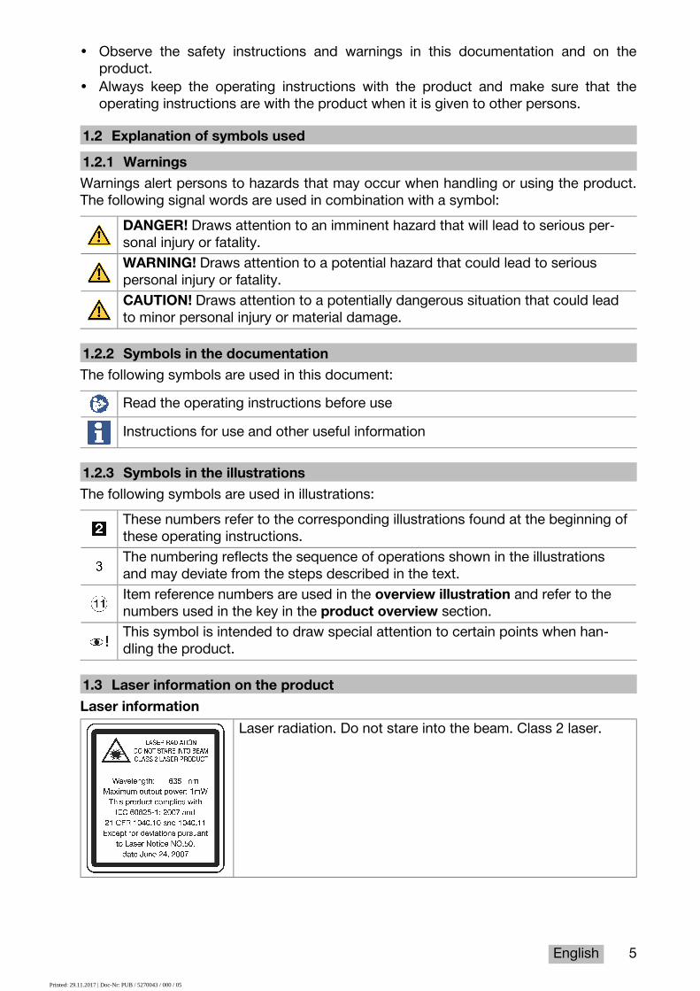
1.2 Explanation of symbols used1.2.1 WarningsWarnings alert persons to hazards that may occur when handling or using the product.The following signal words are used in combination with a symbol:
DANGER! Draws attention to an imminent hazard that will lead to serious per-sonal injury or fatality.WARNING! Draws attention to a potential hazard that could lead to seriouspersonal injury or fatality.CAUTION! Draws attention to a potentially dangerous situation that could leadto minor personal injury or material damage.
1.2.2 Symbols in the documentationThe following symbols are used in this document:
Read the operating instructions before useInstructions for use and other useful information
1.2.3 Symbols in the illustrationsThe following symbols are used in illustrations:
These numbers refer to the corresponding illustrations found at the beginning ofthese operating instructions.The numbering reflects the sequence of operations shown in the illustrationsand may deviate from the steps described in the text.Item reference numbers are used in the overview illustration and refer to thenumbers used in the key in the product overview section.This symbol is intended to draw special attention to certain points when han-dling the product.
1.3 Laser information on the productLaser information
Laser radiation. Do not stare into the beam. Class 2 laser.
Printed: 29.11.2017 | Doc-Nr: PUB / 5270043 / 000 / 05

6 English
1.4 Declaration of conformityWe declare, on our sole responsibility, that the product described here complies withthe applicable directives and standards. A copy of the declaration of conformity can befound at the end of this documentation.The technical documentation is filed here:Hilti Entwicklungsgesellschaft mbH | Tool Certification | Hiltistrasse 6 | D-86916 Kaufering,Germany
1.5 Product informationHilti products are designed for professional use and may be operated, serviced andmaintained only by trained, authorized personnel. This personnel must be informed ofany particular hazards that may be encountered. The product and its ancillary equipmentmay present hazards when used incorrectly by untrained personnel or when used not asdirected.▶ Write down the serial number in the table below. You will be required to state the
product details when contacting Hilti Service or your local Hilti organization to enquireabout the product.Product informationType: PD-C | PD-CSGeneration: 01Serial number:
2 Safety2.1 Basic information concerning safety
CAUTIONPossible hazard or risk of electric shock or burning injuries! Attempting toremove the battery presents a risk of electrical hazards, e.g. short circuiting, burninginjuries and leakage of harmful substances.▶ Do not attempt to open the product. Have the battery replaced only by Hilti
Service.
CAUTIONPossible hazard or risk of electric shock or burning injuries! Ingress of liquidssuch as rainwater, dew or condensation, etc. into the product presents a risk ofelectrical hazards, e.g. short circuiting, burning injuries and explosion.▶ Keep the product clean and dry at all times.▶ Keep the hinged cover cap closed to prevent dampness entering the interior of
the product.
Printed: 29.11.2017 | Doc-Nr: PUB / 5270043 / 000 / 05

English 7
CAUTIONPossible hazards as result of short circuiting, overload and fire. Possiblehazards due to heat radiation, ejection of molten material or chemical reactionscaused by short circuiting, overloading or through resulting fire.▶ Do not expose the product to high temperatures or fire. The battery contained in
the tool could explode or release toxic substances.▶ Use only the approved USB AC adapter with standard micro-USB cable.▶ Under abusive conditions, liquid may be ejected from the battery. Avoid contact
with this liquid. Rinse with water if contact occurs. In the event of eye contactwith the liquid, a doctor should also be consulted. The liquid that leaks from abattery may cause skin irritation or burns.
WARNINGWarning: hazardous high-frequency or low-frequency electromagnetic radia-tion! Electromagnetic radiation may cause spontaneous activation/starting. Theemission of radiation may cause interference to other devices.▶ Do not use the product in the proximity of persons who have a cardiac pacemaker.▶ Do not use the product in the proximity of medical instruments and appliances.▶ Operation of the product in the proximity of military installations, airports, radio
astronomy facilities or in aircraft is not permissible unless prior permission hasbeen obtained.
CAUTIONVisible and invisible laser radiation present hazards. Looking into the laser beamcauses eye damage.▶ Secure the area in which you will be taking measurements. Take care to avoid
directing the laser beam toward other persons or toward yourself when settingup the product.
▶ Do not look directly into the light source. In the event of direct eye contact withthe laser beam, close your eyes and move your head out of the path of the laserbeam.
▶ Keep laser tools out of reach of children.
CAUTIONUnintentional activation of the laser beam presents a hazard. The laser beammay be switched on by inadvertently pressing a measure command button or by asoftware error.▶ Avoid unintentional activation of the laser beam.▶ When handling the product, always bear in mind that the laser beam could be
switched on inadvertently. Before looking toward the path of the laser beam,make sure that the laser beam is switched off or that the product is switched offcompletely.
Printed: 29.11.2017 | Doc-Nr: PUB / 5270043 / 000 / 05
8 English
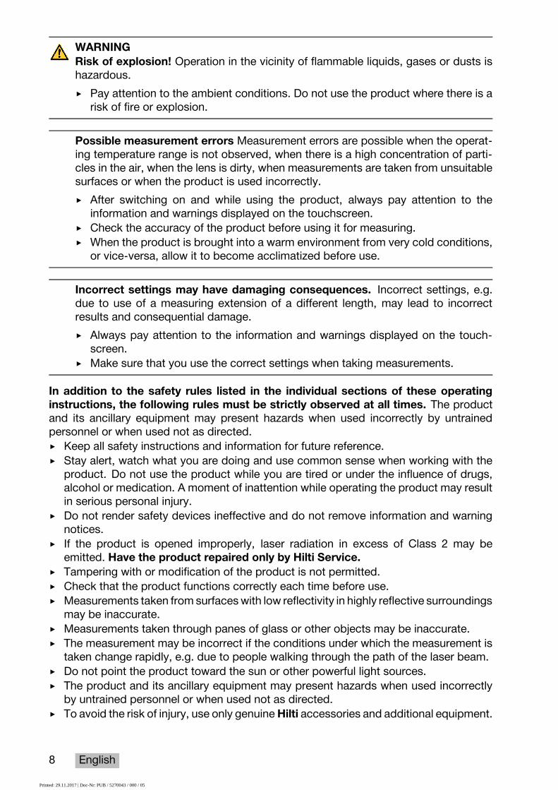
WARNINGRisk of explosion! Operation in the vicinity of flammable liquids, gases or dusts ishazardous.▶ Pay attention to the ambient conditions. Do not use the product where there is a
risk of fire or explosion.
Possible measurement errors Measurement errors are possible when the operat-ing temperature range is not observed, when there is a high concentration of parti-cles in the air, when the lens is dirty, when measurements are taken from unsuitablesurfaces or when the product is used incorrectly.▶ After switching on and while using the product, always pay attention to the
information and warnings displayed on the touchscreen.▶ Check the accuracy of the product before using it for measuring.▶ When the product is brought into a warm environment from very cold conditions,
or vice-versa, allow it to become acclimatized before use.
Incorrect settings may have damaging consequences. Incorrect settings, e.g.due to use of a measuring extension of a different length, may lead to incorrectresults and consequential damage.▶ Always pay attention to the information and warnings displayed on the touch-
screen.▶ Make sure that you use the correct settings when taking measurements.
In addition to the safety rules listed in the individual sections of these operatinginstructions, the following rules must be strictly observed at all times. The productand its ancillary equipment may present hazards when used incorrectly by untrainedpersonnel or when used not as directed.▶ Keep all safety instructions and information for future reference.▶ Stay alert, watch what you are doing and use common sense when working with the
product. Do not use the product while you are tired or under the influence of drugs,alcohol or medication. A moment of inattention while operating the product may resultin serious personal injury.
▶ Do not render safety devices ineffective and do not remove information and warningnotices.
▶ If the product is opened improperly, laser radiation in excess of Class 2 may beemitted. Have the product repaired only by Hilti Service.
▶ Tampering with or modification of the product is not permitted.▶ Check that the product functions correctly each time before use.▶ Measurements taken from surfaces with low reflectivity in highly reflective surroundings
may be inaccurate.▶ Measurements taken through panes of glass or other objects may be inaccurate.▶ The measurement may be incorrect if the conditions under which the measurement is
taken change rapidly, e.g. due to people walking through the path of the laser beam.▶ Do not point the product toward the sun or other powerful light sources.▶ The product and its ancillary equipment may present hazards when used incorrectly
by untrained personnel or when used not as directed.▶ To avoid the risk of injury, use only genuine Hilti accessories and additional equipment.
Printed: 29.11.2017 | Doc-Nr: PUB / 5270043 / 000 / 05

English 9
▶ Observe the information printed in the operating instructions concerning operation,care and maintenance.
▶ Never use the product without having received the appropriate instruction on its useor without having read this documentation.
▶ Due to the principle employed, the results of measurements may be negatively affectedby the surrounding conditions. This includes, e.g. close proximity to equipment thatgenerates powerful magnetic or electromagnetic fields, taking measurements fromunsuitable surfaces and use of unsuitable reflectors.
▶ Measurements to plastic foam surfaces, e.g. polystyrene foam, to snow or to highlyreflective surfaces, etc. may result in incorrect readings.
2.2 Proper preparation of the working area▶ Avoid unfavorable body positions when working from ladders. Make sure you have a
safe stance and that you stay in balance at all times.▶ Secure the site at which you are taking measurements and take care to avoid directing
the laser beam toward other persons or toward yourself.▶ Use the product only within its specified limits. Do not direct the laser beam toward
mirrors, stainless steel, polished stone or similar surfaces.▶ Keep the laser exit window clean in order to avoid measurement errors.▶ Observe the accident prevention regulations applicable in your country.
2.3 Electromagnetic compatibilityAlthough the laser range meter complies with the strict requirements of the applicabledirectives, Hilti cannot entirely rule out the possibility of interference to the laserrange meter caused by powerful electromagnetic radiation, possibly leading to incorrectoperation. Accuracy must be checked by taking measurements by other means whenworking under such conditions or if you are unsure. Likewise, Hilti cannot rule out thepossibility of interference with other devices (e.g. aircraft navigation equipment). The laserrange meter complies with the requirements of class A: The possibility of interferenceoccurring in a domestic environment cannot be excluded.
2.4 Working safely with laser tools▶ Laser Class 2 tools may be operated only by appropriately trained persons.▶ Laser beams should not be projected at eye height.▶ Precautions must be taken to ensure that the laser beam does not unintentionally
strike highly reflective surfaces.▶ Precautions must be taken to ensure that persons do not stare directly into the beam.▶ The laser beam must not be allowed to project beyond the controlled area.▶ Switch the laser tool off when it is not in use.▶ Activate the locking function in the tool settings in order to prevent unauthorized
persons, especially children, from activating the laser beam.▶ Store laser tools, when not in use, in places to which unauthorized persons have no
access.
2.5 General safety rules▶ Check the product for damage before use. Have the damage repaired by Hilti Service.▶ Before using the product, just to be sure, check the product’s preset settings and any
settings you have made yourself.▶ Do not use the product while you are driving a vehicle or operating a machine.
Printed: 29.11.2017 | Doc-Nr: PUB / 5270043 / 000 / 05

10 English
▶ Check the accuracy of the product after it has been dropped or subjected to othermechanical stresses.
▶ Although the product is designed for the tough conditions of jobsite use, as with othermeasuring instruments it should be treated with care.
▶ Although the product is protected against the entry of moisture, it should be wipeddry before being put away in its transport container.
▶ Store tools and appliances out of reach of children when not in use. Do not allowpersons who are unfamiliar with the product, or with these instructions, to operate theproduct. Tools or appliances are dangerous in the hands of untrained, inexperiencedpersons.
Printed: 29.11.2017 | Doc-Nr: PUB / 5270043 / 000 / 05
English 11
3 Introduction to the tool3.1 Product overview
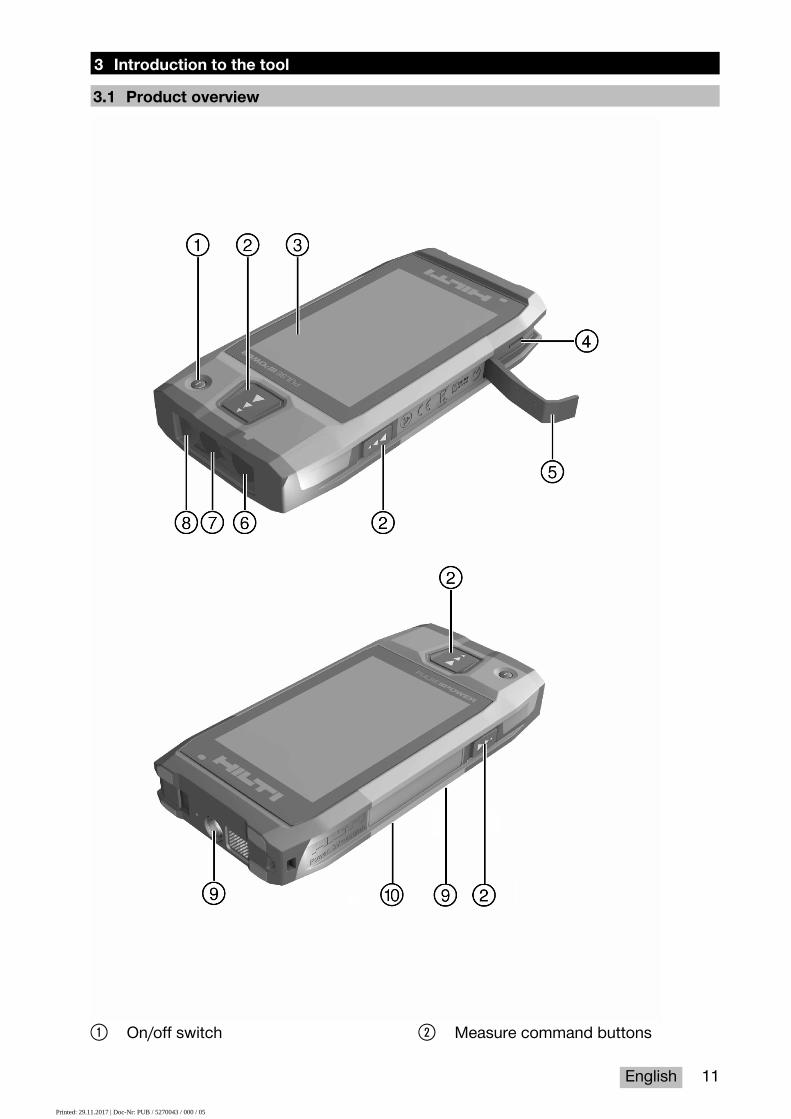
@ On/off switch ; Measure command buttons
Printed: 29.11.2017 | Doc-Nr: PUB / 5270043 / 000 / 05

12 English
= Touchscreen% Micro-USB socket, type B& Hinged cover( Laser exit window
) Camera lens+ Glass cover§ Tripod thread/ Image-recording camera (PD-CS)
3.2 Intended useThe product described is a laser range meter. It is designed to be used for measuringdistances. The measured distances can be used in conjunction with a wide range ofcalculation functions, e.g. areas, volumes, minimum/maximum distances, Pythagorascalculations, laying out, etc.
3.3 Items suppliedLaser range meter, wrist strap, soft pouch, short measuring extension, power supply unitwith micro-USB cable.Other system products approved for use with this product can be found at your localHilti Store or online at: www.hilti.group.
3.4 Integrated batteryThe product comes with a permanently integrated 3220 mAh Li-ion battery.The Li-ion battery will typically last for 500 full charging cycles or at least two years ofmoderate to heavy use.When the battery is discharged, the charging operation lasts for roughly three hours –provided that the USB cable and plug adapter supplied by Hilti are used.
NoteIf, at the start of the charging operation, the battery was completely or almostcompletely discharged, the charging signal may only appear after roughly 30minutes.
At temperatures over 30 °C (86 °F), the time required to charge the battery willincrease considerably. Optimal battery charging times are achieved at normal interiortemperatures, away from direct sunlight.In the case of very high exterior temperatures, i.e. 32 °C (90 °F) and over, the chargingoperation will take longer. The charging operation may even be automatically interruptedin order to maintain a safe battery temperature.The charging operation may take longer if the USB cable supplied by Hilti is connectedto a PC for charging.We do not recommend using micro-USB cables from other manufacturers. If this cannotbe avoided, you should first ensure that the cable in question is suitable for use with5.0 V/2.1 A power sources. The time required to charge the tool may be significantlyincreased if a different make of micro-USB cable is used. If a micro-USB cable fromanother manufacturer is regularly used in place of the one supplied by Hilti, this mayimpair the battery life.▶ When starting the tool for the first time, ensure that the battery is completely charged
before putting the tool into operation.▶ Do not charge the tool in direct sunlight.▶ If the charging operation stops or is taking a very long time, try to find a cooler
environment in which to charge the battery.▶ If there is anything unusual about the battery charging operation or if the battery life
falls below two hours, contact your Hilti Service team.
Printed: 29.11.2017 | Doc-Nr: PUB / 5270043 / 000 / 05

English 13
▶ The tool should only be charged using the micro-USB cable supplied by Hilti. Connectthe cable to a USB port on a PC or, using the plug adapter supplied, a power outlet.
▶ If you lose the micro-USB cable or the plug adapter supplied with the tool, contactyour Hilti Service team for a replacement.
WARNINGRisk of injury caused by the laser beam. Failure to follow the correct procedureswhen opening may cause uncontrolled emission of laser radiation.▶ Always have repairs carried out by Hilti Service.
▶ The Li-ion battery must be replaced by Hilti Service as the tool has to be reconfiguredonce the battery has been replaced.
3.5 Technical data3.5.1 Distance measurement
NoteDistance and inclination measurement accuracy: Influences such as sharptemperature fluctuations, moisture, shock, dropping, etc. can affect accuracy.Unless otherwise stated, the tool was adjusted or calibrated under standardambient conditions (MIL-STD-810G). As a basic principle, when taking distancemeasurements allow for an additional distance-dependent error of 0.02 mm permeter. The reference for inclination measurements is the rear face of the tool.
PD-C PD-CSOperating modes • Single measurements
• Range (multiple) mea-surements
• Single measurements• Range (multiple) mea-
surementsDistance measurement ac-curacy (2σ, standard devia-tion)
±1.0 mm ±1.0 mm
Inclination measurement ac-curacy (2σ, standard devia-tion)
±0.3° ±0.3°
Beam divergence 0.20 mrad …0.45 mrad 0.20 mrad …0.45 mradMeasuring range with targetplate
0 m …200 m(0 ft …656 ft)
0 m …200 m(0 ft …656 ft)
Minimum distance for aim-ing with the laser point andcross hairs without use ofthe zoom function
> 2 m(> 6 ft - 10 in)
> 2 m(> 6 ft - 10 in)
Minimum distance for aim-ing with the laser point andcross hairs at the maximumzoom setting
> 5 m(> 16 ft)
> 5 m(> 16 ft)
Printed: 29.11.2017 | Doc-Nr: PUB / 5270043 / 000 / 05

14 English
3.5.2 TouchscreenIndicators Continuous display of distance, operating status and
battery charge statusTouchscreen diagonal size 10.16 cm
(4.00 in)
3.5.3 Power supplyLiion battery Built-inRated voltage 3.7 VCapacity 3,220 mAhStandby time > 200 hLength of time until the au-tomatic sleep mode is acti-vated
20 min
Battery life under normaloperating conditions, displayswitched on
≈ 10 h
Charging time (depending onbattery charger and chargingcable)
≈ 3 h
Battery charger input volt-age
100 V …240 V
Battery charger input fre-quency
50 Hz …60 Hz
Battery charger rated cur-rent
0.5 A
Battery charger output volt-age
5 V
Charging current 10 mA …2,100 mACharging cable plug stan-dard
Micro-USB
3.5.4 LaserPD-C PD-CS
Laser class Visible, laser class2, IEC/EN 60825-1:2007; Class 2CFR 21 § 1040 (FDA)
Visible, laser class2, IEC/EN 60825-1:2007; Class 2CFR 21 § 1040 (FDA)
Wavelength 635 nm 635 nmOutput power < 1 mW < 1 mWTime until activation ofpower-saving mode
20 s 20 s
Printed: 29.11.2017 | Doc-Nr: PUB / 5270043 / 000 / 05

English 15
3.5.5 Other characteristics of the productPD-C PD-CS
Internal flash memory ca-pacity for saving measure-ments
≈ 3,000NoteThe value given is basedon typical direct mea-surements with targetphoto. The actual max-imum depends on thetype of measurementsand the resolution of thephotos.
≈ 7,000NoteThe value given is basedon typical direct mea-surements with targetphoto. The actual max-imum depends on thetype of measurementsand the resolution of thephotos.
Aiming camera maximumresolution [megapixels]
5.0 5.0
Image-recording camera[megapixels]
5.0 5.0
Bluetooth version 2.1 + EDR (3 Mbit/s) 2.1 + EDR (3 Mbit/s)Wireless LAN •/• Complies with the stan-
dard: IEEE 802.11 b/g/n,supported channels: 1 -11
Bluetooth transmittingpower
12.3 dBm 15.39 dBm
Wireless LAN transmittingpower
•/• 18.47 dBm
Frequency 2,400 MHz …2,483.5 MHz 2,400 MHz …2,483.5 MHzWeight 260 g
(9.2 oz)260 g(9.2 oz)
Dimensions 154 mm × 75 mm× 24 mm(6.1 in × 3.0 in × 0.9 in)
154 mm × 75 mm× 24 mm(6.1 in × 3.0 in × 0.9 in)
Protection class IP54 IP54Operating temperature −15 ℃ …50 ℃
(5 ℉ …122 ℉)−15 ℃ …50 ℃(5 ℉ …122 ℉)
Storage temperature −15 ℃ …50 ℃(5 ℉ …122 ℉)
−15 ℃ …50 ℃(5 ℉ …122 ℉)
3.6 Basic principleThe tool determines the distance along a laser beam emitted by the tool to the point atwhich the beam strikes a reflective surface. The red laser spot ensures that the targetis clearly identifiable. The range is dependent on ambient light levels as well as thereflectance and structure of the target surface from which measurements are taken.
Printed: 29.11.2017 | Doc-Nr: PUB / 5270043 / 000 / 05
16 English
3.7 Navigating on the display3.7.1 Preparations at the workplace
CAUTIONRisk of injury! Inadvertent starting of the product.▶ Remove the battery before making any adjustments to the power tool or before
changing accessories.
Observe the safety instructions and warnings in this documentation and on the product.
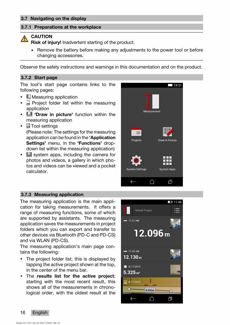
3.7.2 Start pageThe tool’s start page contains links to thefollowing pages:• Measuring application• Project folder list within the measuring
application• ‘Draw in picture’ function within the
measuring application• Tool settings
(Please note: The settings for the measuringapplication can be found in the ‘ApplicationSettings’ menu, in the ‘Functions’ drop-down list within the measuring application)
• system apps, including the camera forphotos and videos, a gallery in which pho-tos and videos can be viewed and a pocketcalculator.
3.7.3 Measuring applicationThe measuring application is the main appli-cation for taking measurements. It offers arange of measuring functions, some of whichare supported by assistants. The measuringapplication saves the measurements in projectfolders which you can export and transfer toother devices via Bluetooth (PD-C and PD-CS)and via WLAN (PD-CS).The measuring application’s main page con-tains the following:• The project folder list; this is displayed by
tapping the active project shown at the top,in the center of the menu bar.
• The results list for the active project;starting with the most recent result, thisshows all of the measurements in chrono-logical order, with the oldest result at the
Printed: 29.11.2017 | Doc-Nr: PUB / 5270043 / 000 / 05

English 17
end of the list. Details relating to a specificresult can be displayed by tapping it.
• The icon for the ‘Functions’ drop-downmenu; this is located in the upper-rightcorner of the display. The drop-down menucontains all of the measuring functions (seethe overview of functions, → page 21), andthe ‘Application Settings’ menu with thesettings for the measuring application canbe found at the end of the list.
3.7.4 ToolbarThe toolbar is displayed during the measure-ment. It allows you to activate assistants,switch between the permanent laser and thestandard laser, switch on the aiming cameraand change the reference position.
3.7.5 Navigation barThe navigation bar is always found at the loweredge of the display, and includes the followingelements:• : End a function and return to the previ-
ous view or the last menu displayed.• : Return to the start page.• : Display all active applications and end
or select individual ones.
3.8 Buttons and icons for triggering and ending measurementsAfter switching on the laser, a measurement can always be taken using one of thethree rubber measure buttons. For the majority of the functions, you can also takemeasurements using the measure button icon on the display once the tool is in positionand ready to measure.If you take a measurement when the range is shown before the measurement is triggered,you can take the measurement by tapping on the displayed range. In the case of range(multiple) measurements, you can also end the measurement by tapping on the displayeddistance.
NotePressing one of the three measure buttons will take you directly to the ‘Direct’function.
3.8.1 Ending measurements and functionsYou can end any measurement or function using .
3.9 Inclination sensorThe inclination sensor incorporated in the PD-C and PD-CS allows calculations to bemade using indirect measurements. The integrated inclination sensor measures thehorizontal inclination. In order to achieve greatest possible accuracy when makinginclination measurements, the inclination sensor must be adjusted at regular intervals.Observe the instructions given in the tool software relating to regular adjustment. You
Printed: 29.11.2017 | Doc-Nr: PUB / 5270043 / 000 / 05

18 English
must also adjust the tool after it has been exposed to a change of temperature or if it hasbeen subjected to an impact.The tool is not designed for taking precise angle measurements. We recommend youuse a spirit level or a suitable precision tool for this purpose.
3.10 Measuring aids3.10.1 Measuring extension PDA 72The PDA 72 measuring extension is made from aluminum and is equipped with a non-conductive synthetic rubber grip. If the PDA 72 measuring extension (optional accessory)is screwed onto the base of the tool, a dialog appears in which you have to confirmselection of the measuring extension. The PDA 72 measuring extension can also bescrewed to the rear of the tool.
3.10.2 Short measuring extensionThe product package contains a short measuring extension (folding spike). This foldingspike is designed to allow you to work with points of reference in places otherwiseinaccessible to the flat base of the tool.The folding spike is helpful when measuring diagonally across rooms or when pointsof reference are hard to access. Observe the notes on optimizing measuring accuracy→ page 35.▶ The folding spike should be regularly used in certain indirect and Pythagoras mea-
surements to retain the same point of reference for all partial measurements.▶ Insert the folding spike into the holder on the tool cover for safe storage.In its original condition, the folding spike has a rounded end. Long-term use of the foldingspike may result in abrasion of this point.▶ If the folding spike has been flattened by use, or if you have lost the folding spike,
please contact Hilti Service.
3.10.3 Fitting a measuring extension to the base of the toolNoteA measuring extension will be detected automatically (and taken into accountaccordingly) only when a genuine Hilti PDA 74 measuring extension (short versionfor the PD-C and PD-CS, supplied with the product) or a genuine Hilti PDA 72measuring extension (long version for the PD-I, PD-E, PD-C and PD-CS, availableseparately) is screwed into the base of the tool.Other extensions or tripods may also be used. When one of these is screwed intothe base of the tool, you must then carefully determine the offset distance andmanually enter this value in the tool.
1. Switch the tool on and unlock the display.2. Screw the measuring extension into the
base of the tool.◁ You will be requested to make a selec-
tion.3. Select the matching measuring extension
or enter the offset distance.
Printed: 29.11.2017 | Doc-Nr: PUB / 5270043 / 000 / 05

English 19
3.10.4 Target platesFor larger ranges and in unfavorable light conditions, we recommend use of the PDA 50,PDA 51 or PDA 52 target plates.For reliable measurements, care should be taken to ensure that the laser beam strikesthe target plate at right angles, as far as possible.
NoteWhen the PDA 50 and PDA 52 target plates are used and very high accuracy isrequired, add a value of 2 mm (0.1 inches) to the measurement obtained.This distance value can be entered manually. Select the reference setting beforeor after the measurement and enter a numerical offset of 0.0025 m or 1/16 inches.
3.10.4.1 Target plate PDA 50The PDA 50 target plate is made of durable plastic with a special reflective coating. Useof the target plate is recommended at distances greater than 10 m in unfavorable lightconditions.
3.10.4.2 Target plate PDA 51The PDA 51 target plate has no reflective coating and its use is recommended inunfavorable light conditions and at shorter distances.
3.10.4.3 Target plate PDA 52The PDA 52 target plate is equipped with the same reflective coating as the PDA 50 butis considerably larger in size (210 x 297 mm). This makes it much easier to aim the toolat the target plate over long distances.
3.11 Measuring very short distancesThe shortest distance that the tool can reliably measure under typical operating conditionsis 15 cm (US: 6 inches). However, the minimum spacing for a reliable surface can beup to 1.5 m if the target has a non-reflective color or surface, such as dark black, or asmooth, velvety surface structure. If the measurement is not reliable, the tool will notdisplay a result.
3.12 Measuring accuracyThe accuracy of the laser distance measurement, from the tool’s reference position tothe laser spot, is determined with a maximum deviation of 1.0 mm. If a target cannot bereached or bright sunlight does not permit this level of precision, no result is displayed.Measuring accuracy when using the ‘Indirect’, ‘Pythagoras’ and ‘Picture’ functions may,under typical operating conditions and without careful use of a tripod, lie significantlybeyond ±1.0 mm. The deviation depends on how exactly you retain the reference positionfor each of the measurements required to calculate the end result. Continuous use of theshort measuring extension makes it easier to swivel the tool around a single, unchangedstarting point. On the other hand, rotating the tool without using a measuring extensionor a tripod will often cause slight deviation from the exact reference position.The measuring accuracy when using the ‘Picture’ function depends on whether the toolis positioned at an exact angle of 90° to the target (at both horizontal and vertical rightangles) and on whether the whole surface surveyed in the target picture is genuinelylevel, such as a facade or a ceiling. The following table shows the typical deviations formeasurements in photos when the photo was not taken from a 90° angle.
Printed: 29.11.2017 | Doc-Nr: PUB / 5270043 / 000 / 05

20 English
Errors caused by surveying from a position not at right angles to the wallThe following table presupposes that the vertical 90° angle against the wall is maintainedusing the inclination indicator on the range meter.The data on error percentages in the table estimates the deviation of the measurement inrelation to the corresponding real distance.Limitations• Individual adjustment of tools is not taken into account.• Values apply to freehand measurements.• If a tripod is used, the accuracy is increased by approximately 0.5%.
Length of the line drawn on the screen in relation to thewidth of the screen (without zoom)
Deviation from thehorizontal 90°
angle against thewall
< 30% 30% to 50% > 50% to 100%
0° ±4.5% ±2.5% ±2.2%maximum ±3° ±5.2% ±3.7% ±4.9%
3.12.1 ‘Picture’ for advanced usersIf the procedure is carried out with due care, aiming the laser at a horizontal or verticalline at a 90° angle allows advanced users to use the ‘Picture’ function to determine adistance along the line. This method must be used with caution, as all of the distancesdetermined in the picture that do not lie along a line surveyed at a 90° angle will besignificantly less accurate.
3.12.2 The influence of surfaces on the measurementThe Hilti laser module, developed on the basis of PulsePower (millions of pulses persecond), offers the best conditions for reception of an ample number of distinct samplesof reflected laser light, which are used to calculate precise measurements.However, there are situations in which the tool will not receive a sufficient amount ofreflected light from the target. Understanding this principle means that certain remediesare possible, such as the use of target plates from Hilti, available as an accessory. Use oftarget plates allows a substantially larger amount of light to be reflected from the targetto the tool.Examples of situations where an insufficient amount of light is reflected include missedtargets (e.g. a laser beam that misses the ceiling and is instead aimed at the sky),luminous, non-reflective surfaces, obstructions such as mist, rain or dust between thetool and the target, non-reflective dark surfaces or surfaces with a velvety structure,materials that absorb light, such as foam, or rough surfaces.
3.12.2.1 Rough surfacesWhen measuring to rough surfaces, such as rough plaster, an average distance value isestablished with the center of the laser spot weighted higher than the edges of the laserspot.
3.12.2.2 Curved or inclined surfacesIf the laser beam strikes the target surface at a very narrow angle, the light reflected maybe inadequate. Conversely, too much light may be reflected toward the tool in situations
Printed: 29.11.2017 | Doc-Nr: PUB / 5270043 / 000 / 05
English 21
where the laser beam strikes the target perpendicularly. We recommend use of a targetplate (PDA 50, PDA 51 or PDA 52) in both of these situations.
3.12.2.3 Wet or shiny surfacesA still, calm pond reflects both the clouds and light from the sky. A shiny, wet surfacereflects the laser light in a similar way. If the targeted surface is wet and shiny, it isimportant that the measurement is taken at right angles, as far as possible, as otherwisethe light will be reflected in a different direction and too little light will return to the tool tocalculate a measurement.Curved surfaces can also make it more difficult to reflect enough light in the direction ofthe tool for a measurement to be taken.
3.12.2.4 Transparent surfaces or surfaces that absorb lightIt is generally possible to measure distances to transparent or semi-transparent materials,e.g. liquids, polystyrene foam, etc.. However, as light penetrates these materials,measuring errors may occur.
3.12.2.5 Disruption between the tool and the measuring targetMeasuring errors can occur if, for example, measurements are taken through glass panesor other objects such as dust or aerosols are located between the laser source and themeasuring target.
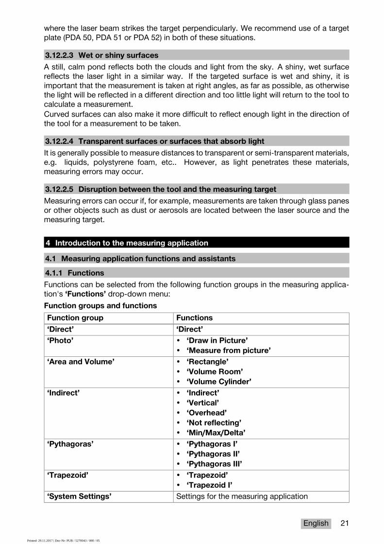
4 Introduction to the measuring application4.1 Measuring application functions and assistants4.1.1 FunctionsFunctions can be selected from the following function groups in the measuring applica-tion's ‘Functions’ drop-down menu:Function groups and functionsFunction group Functions‘Direct’ ‘Direct’‘Photo’ • ‘Draw in Picture’
• ‘Measure from picture’‘Area and Volume’ • ‘Rectangle’
• ‘Volume Room’• ‘Volume Cylinder’
‘Indirect’ • ‘Indirect’• ‘Vertical’• ‘Overhead’• ‘Not reflecting’• ‘Min/Max/Delta’
‘Pythagoras’ • ‘Pythagoras I’• ‘Pythagoras II’• ‘Pythagoras III’
‘Trapezoid’ • ‘Trapezoid’• ‘Trapezoid I’
‘System Settings’ Settings for the measuring application
Printed: 29.11.2017 | Doc-Nr: PUB / 5270043 / 000 / 05

22 English
4.1.2 Measuring with the help of the trigger, timer and aiming cameraBefore taking a measurement, you can activatethe following assistants to provide support fordistance measurements using the icon onthe ( → page 17) toolbar:• Triggers provide support by automatically
taking a measurement when distance mea-surements have to be taken at an anglewhich is exactly horizontal or vertical, orwhen the longest or shortest distance withina continuous measurement sequence hasto be determined.
• Timers provide the option of taking a mea-surement 3, 5, 10 or 15 seconds after themeasure button is pressed.
• Measuring target tracking using the aimingcamera provides support when aiming atmeasuring targets that are difficult to see.
Possible combinations of assistants and functions
Function AssistantTrigger Timer Aiming camera
‘Direct’ ✓ ✓ ✓‘Measure from pic-ture’
✓ ✓ ✓
‘Draw in Picture’ ✓ ✓ ✓‘Area and Volume’ ✓ ✓ ✓‘Indirect’ ✓ ✓ ✓‘Not reflecting’ Yes, for the first
measurement. Notfor the second mea-surement (anglemeasurement only)
Yes, for the firstmeasurement. Notfor the second mea-surement (anglemeasurement only)
✓
‘Min/Max/Delta’ Not applicable Not applicable ✓‘Pythagoras’ ✓ ✓ ✓‘Trapezoid’ ✓ ✓ ✓
4.1.3 Standard laser (single measurement)In ‘Standard Laser’mode, after a measurebutton is pressed and the measurement istaken, the laser is switched off.The current mode ‒ ‘Standard Laser’ or ‘Per-manent Laser’ ‒ is displayed as an icon onthe status bar on the main screen.
Printed: 29.11.2017 | Doc-Nr: PUB / 5270043 / 000 / 05
English 23
4.1.4 Permanent laser (multiple measurement)In ‘Permanent Laser’ mode, the laser is notswitched off after a measure button is pressedand the measurement is taken, instead remain-ing on. This means that measurements can becarried out in quick succession without havingto repeatedly switch the tool on.The current mode ‒ ‘Standard Laser’ or ‘Per-manent Laser’ ‒ is displayed as an icon onthe status bar on the main screen.
4.1.5 Using the aiming cameraAiming with the help of the camera facilitatesaccurate orientation of the laser range meter,even at longer distances.Minimum spacing required for use of the aiming camera's cross hairsThe aiming camera makes it easier to accurately position the laser spot. This is usefulboth outside in daylight and in the case of larger interior distances, i.e. whenever it isdifficult or impossible to distinguish the laser spot.The aiming camera and the laser are located next to each other, two to three centimeters(roughly an inch) apart. As a result, when measuring short distances, the laser spot andthe center of the cross hairs cannot be aligned. This behavior is normal and is causedby the same parallax error that allows you to see two fingers if you hold a single fingeragainst the tip of your nose. The laser spot and the cross hairs can be aligned from twometers away (roughly 6.5 feet) when the zoom is switched off or from five meters away(roughly 16 feet) when the zoom is set to maximum.
NoteThe measurement is always calculated from the laser spot, regardless of the centerof the cross hairs.
Zoom and brightnessWhen the aiming camera is activated, the zoom and brightness can be adjusted bytapping and swiping.ZoomTapping on the lower edge of the screen activates the zoom setting. A bar on the upperedge of the screen shows the current magnification as a percentage. Swiping left or righton the lower edge of the screen allows you to adjust the magnification.BrightnessTapping on the right edge of the screen activates the brightness setting. A bar on theright edge of the screen shows the current brightness as a percentage. Swiping up ordown on the right edge of the screen allows you to adjust the brightness of the aimingcamera picture.
4.1.6 Measuring referencesReference positions
The reference position is the laser exit window, i.e. the front edge of thetool.
Printed: 29.11.2017 | Doc-Nr: PUB / 5270043 / 000 / 05

24 English
The reference position is the tripod thread on the back of the tool.
The reference position is the tripod thread on the base of the tool.
The laser range meter can measure distances from three different points of contact ormeasuring references. You can switch between the laser exit window, base of the tool andthread on the underside of the tool using the ‘Measuring references’ menu on the toolbar.When screwing a measuring extension or a tripod to the base of the tool (position (9) onthe product overview), the tool will query whether a short or long measuring extension isbeing used or whether a different value has to be entered. The tool automatically setsthe appropriate measuring reference for the selected measuring extension. For otherpurposes, such as a value for a tripod, the result from a new measurement, a saved resultor a numerical input can be used.Offset settingsThe ‘Offset Value’ function automatically increases or reduces all measurements by adefined value. The offset value is set using the following options:• ‘New measurement’: Measure a distance.• ‘Data’: Select a saved measurement.• ‘Numeric Input’: Numerical input, e.g. a distance measured elsewhere.
4.2 Measuring with the help of triggers and timers4.2.1 Activation and deactivationThe icon is used to activate the trigger andthe timer, which provide assistance during themeasuring process. The trigger and timer canbe combined with various measuring functions( → page 22).The ‘Default mode’ option can be used todeactivate the trigger and the timer.
4.2.2 Trigger ‘Minimal’The tool records the shortest distance registered during continuous measurement.
NoteThis measuring program is particularly helpful if a measurement to a target positionhas to be taken completely plumb.
4.2.3 Measuring minimum distance1. Press the "Measure" button once.◁ Continuous measurement begins.
2. Press the "Measure" button again.◁ Continuous measurement ends and the shortest distance determined during
continuous measurement is displayed.
4.2.4 Trigger ‘Maximal’The tool records the greatest distance registered during continuous measurement.
Printed: 29.11.2017 | Doc-Nr: PUB / 5270043 / 000 / 05

English 25
NoteThis measuring program is particularly helpful if a measurement has to be taken ina hard-to-reach area, such at the corner of a ceiling.
4.2.5 Measuring maximum distance1. Press the "Measure" button once.◁ Continuous measurement begins.
2. Press the "Measure" button again.◁ Continuous measurement ends and the longest distance determined during con-
tinuous measurement is displayed.
4.2.6 Trigger ‘Horizontal’During continuous measurement, the tool only records values registered at an incline of 0°.
NoteThis measuring program is particularly helpful if a measurement has to be takenexactly in the horizontal plane but you do not have a tripod to hand. It ensures thatthe tool does not deviate from the horizontal plane.
4.2.7 Measuring horizontal distances1. Press the "Measure" button once.◁ Continuous measurement begins.
2. Aim the tool at approximately 0°.◁ At exactly 0° the tool takes a measurement automatically, ends continuous
measurement and displays the horizontal distance.
4.2.8 Trigger‘Vertical’During continuous measurement, the tool only records values registered at an incline of90°.
NoteThis measuring program is particularly helpful if a measurement has to be taken ata completely vertical angle but you do not have a tripod to hand, by ensuring thatthe tool does not deviate from a vertical orientation.
4.2.9 Measuring vertical distance1. Press the "Measure" button once.◁ Continuous measurement begins.
2. Aim the tool at approximately +90° or -90°.◁ At exactly +90° or -90° the tool takes a measurement automatically, ends continu-
ous measurement and displays the vertical distance.
4.2.10 Delayed measurement using ‘Timer’When measuring using the ‘Timer’ function, the tool takes a delayed measurement afterthe measure button is pressed. This delay can be set to 3, 5, 10 or 15 seconds.
NoteThe ‘Timer’ function cannot be combined with the assisted measuring methods.
Printed: 29.11.2017 | Doc-Nr: PUB / 5270043 / 000 / 05

26 English
4.3 Measurements, managing project folders and exporting data4.3.1 MeasurementsThe tool saves measurements, photos of themeasured targets and any calculations thathave been carried out. Each result can besupplemented with annotations or a photo.With average camera settings and ordinaryuse, approximately 3000 results can be saved.The tool will notify you if the memory capacityis full. Further results can only be saved oncespace has been created in the project folders.Each result is saved in a project folder. Resultsare shown in chronological order, with themost recent result at the top.
4.3.2 Displaying measurementsRegardless of the unit of measurement selected in the ‘Settings’ menu, the measuringapplication shows the calculated results as a numerical value to three decimal places.
NoteThis value, shown to three decimal places, does not provide the real range in thecase of either direct or indirect measurements. Rather, this value represents asaccurate a calculation as possible. In the case of direct measurements, the resultshown may deviate from the actual value by up to ±1 mm.Results produced by indirect calculations do not achieve the same level of accuracyas results from direct calculations.
4.3.3 Managing project foldersYou can add and name projects. If no project folder has been set up, measurements aresaved to a folder labeled ‘Default Project’.If you delete the ‘Default Project’ folder, all of the results in this folder are deleted andthe ‘Default Project’ folder is recreated.Project folders can be renamed or deleted. The last folder used is displayed when thetool is switched back on.Measurements cannot be moved to different project folders.▶ You should therefore ensure that the correct folder for the project has been either
selected or created before taking any measurements.
Printed: 29.11.2017 | Doc-Nr: PUB / 5270043 / 000 / 05

English 27
4.3.4 Buttons for managing project folders▶ The buttons for editing and deleting project
folders and exporting files can be accessedby swiping left on the project folder entry.
▶ Use the pencil icon to rename the project.▶ Use the trash icon to delete the project
along with all of its content.▶ Use the export icon to export all of the
results from the current project into a file.▶ Use the export icon to export individual
results from the current project that werecreated using the ‘Measure from picture’and ‘Draw in picture’ functions.
4.3.5 Exporting dataThe PD-C and PD-CS can share files via Bluetooth or transfer files to a third-partyapplication via WLAN. Third-party applications may be used at the discretion of theuser and at his or her own responsibility. The terms of business or login configurationsmay change through use of third-party applications. Hilti accepts no responsibility andprovides no support for third-party applications.
NoteUsers of Mac computers with Mac OS X 10.5 and later versions, who wish totransfer files from the PD-C to a Mac computer, may download the official filetransfer software from Android. Please visit https://www.android.com/filetransfer/for more information.
The target device for the Bluetooth connection must already be paired in order for the filetransfer to take place.
NoteMany Bluetooth-enabled devices with Android or PCs with various versions ofWindows were successfully paired during the course of our tests. Nevertheless,Hilti cannot guarantee that pairing will work with every device. Apple does not allowthe range meter to transfer files to Apple devices via a Bluetooth connection.Projects can be exported in PDF or CSV format, while results from the ‘Measurefrom picture’ and ‘Draw in Picture’ functions are exported as a JPG file. The filescan also be exported to the flash memory on the range meter. They can then betransferred from the flash memory to a PC using a micro-USB cable.
Printed: 29.11.2017 | Doc-Nr: PUB / 5270043 / 000 / 05

28 English
4.3.6 Exported data in flash memoryNoteResults that are no longer required should be deleted on a regular basis in order toensure that the PD-C and the PD-CS do not reach the limit of their 2 GB memorycapacity.However, even if the sizes of the result files vary, for example because theycontain annotated pictures, typical users can store approximately 3000 results inthe available memory.
Files in flash memory cannot be viewed using the PD-C or the PD-CS on their own. Thecurrent software provides no file management function that will allow the user to view,edit or delete files stored in the flash memory.Once the PD-C is connected to a PC using a micro-USB cable, the root folder of thePD-C should appear in the Windows file system under “My Computer”. The name of thefolder is pdc_export. This folder contains subfolders for all of the exports, chronologicallyordered by the date and time of the export as well as by the name of the project or result.▶ Copy the folder or specific files in the pdc_export directory to your PC.
4.4 Point measurements and range (multiple) measurementsDistance measurements can be carried out as point or range (multiple) measurements.Point measurementsIn point measurements, the range is measured for the targeted point.Range (multiple) measurementsIn range (multiple) measurements, either a minimum or maximum figure is determined forthe scanned area. A range (multiple) measurement is used to set out given distances orlengths and can also be used where distance measurement is otherwise difficult, e.g. atcorners, edges or in niches, etc..During a range (multiple) measurement, the range is displayed virtually in real time. Thespeed at which the display is updated depends on the reflectivity of the target surface.After the measurement is completed, the results page is displayed in the project folder.
4.5 Measuring rangeThe brightness of ambient light has an effect on the measuring range.
4.5.1 Increase rangesThe range of the tool is generally increased when measurements are taken in the dark, atdawn or dusk and when the target and/or the tool is shaded from bright light.Use of the PDA 72 measuring extension or a tripod increases the likelihood of successfulmeasurement at long distances by making it easier for the tool to receive reflected beams.Use of target plates also allows you to increase the range of the tool ( → page 19).
4.5.2 Reduced rangesMeasuring range may be reduced if ambient light is very bright, e.g. in bright sunlight orwhen working under very powerful floodlights.Measurements taken to mat green, blue or black surfaces may reduce the range of thetool to the same extent as wet or shiny surfaces.The range may be reduced or the result distorted if objects are located in the path of thelaser beam or if measurements are taken through glass.
Printed: 29.11.2017 | Doc-Nr: PUB / 5270043 / 000 / 05

English 29
4.6 Recording measuring targets with the help of the camera1. Tap on the "Camera" icon.2. Record the target using the camera and align the cross hairs over it.3. Take the measurement.4. Tap on the "Camera" icon again if you no longer wish to work with the camera's
assistance.
5 Preparation and settings5.1 Charging the built-in battery▶ Charge the internal battery completely before using the tool for the first time (see
→ page 12).
5.2 Switching on and off, standby mode and unlocking5.2.1 Switching on1. Press the on/off switch briefly.◁ The product will be ready for use after 15–20 seconds. The locked display is shown.
2. To unlock the display, swipe the lock symbol off the screen to the right.◁ The measurements for the currently active project are displayed and can be
used to select functions.
5.2.2 Standby mode or switching offAfter normal use, the range meter can either be switched off or set to standby mode. Thetool automatically switches to standby mode after a certain length of time without use.If the battery is fully charged and Bluetooth is deactivated, the tool can remain in standbymode for between one week and one month before it has to be recharged. This meansthat standby mode is ideal for normal daily use.
5.2.3 Activating standby mode▶ Press the on/off switch briefly.◁ The display switches off and the tool goes into standby mode.
NoteIf the range meter is in standby mode, it can be reactivated using any of the fourbuttons.
5.2.4 Unlocking the toolNoteIf the tool has not been used for some time, it switches to sleep mode and thedisplay is locked.
1. Press one of the four buttons on the tool.◁ The display switches on and the lock symbol is shown.
2. To unlock the display, swipe the lock symbol off the screen to the right.◁ The tool is unlocked.
NotePressing one of the three measure buttons will take you directly to the ‘Direct’function.
Printed: 29.11.2017 | Doc-Nr: PUB / 5270043 / 000 / 05

30 English
5.2.5 Switching offNoteIf you will not need the tool in the next few days or if you will have to go for a longtime without charging the battery, all you have to do is switch the tool off.
1. Press the on/off switch for several seconds.2. Select ‘Switch off’ from the menu.3. Confirm the settings by pressing ‘OK’.◁ The tool vibrates twice and switches itself off.
5.3 Adjusting the inclination sensorNoteRegular adjustment of the inclination sensor helps ensure high measuring accuracy.This applies to indirect measurements in particular, the results of which rely on theaccuracy of the inclination sensor.(The inclination sensor does not influence the accuracy of the laser in directmeasurements.)
1. Select the option ‘Settings’ and ‘Adjusting the inclination sensor’ from the ‘Func-tions’ menu.
2. Lay the tool on a flat surface with the display facing upwards.3. Press the "Measure" button.4. Rotate the tool, without lifting it off the surface, until it points in the opposite direction.5. Press the "Measure" button.◁ The inclination sensor is adjusted.
5.4 Establishing a Bluetooth connectionNoteIf you are connecting the range meter to another device via Bluetooth for the firsttime, ensure that Bluetooth is activated on the other device and that the counterpartdevice is set to be visible to other devices. Without taking these two steps, it maynot be possible to connect the range meter to the other device.
1. Open the tool settings on the start page.2. Switch on the "Bluetooth" option in the "WIRELESS & NETWORKS" section.3. Select "More...".◁ The tool searches for suitable Bluetooth devices.
4. In the settings on the device to which you want to connect the tool, ensure that thedevice is visible to other devices and that it is able to connect to new devices. Furtherinformation may be included in the documentation for the respective devices.
5. If no Bluetooth devices were found, select "Search for devices".6. Select the device you wish to pair with under "Available devices" as soon as it is
displayed.7. Confirm the pairing by pressing "Yes" or "Pair".
NoteYou can increase the battery life of the Li-ion battery if you deactivate Bluetoothafter carrying out a data transfer.
Printed: 29.11.2017 | Doc-Nr: PUB / 5270043 / 000 / 05
English 31
5.5 Establishing a WLAN connectionPD-CS
1. Open the system settings.2. Activate WLAN in the Wireless and networks section.3. Select the desired network.
5.6 Settings for the measuring applicationSetting Description‘Length unit’ Selecting the unit of length for distance measurement
For Japan: Tools registered in Japan are only able towork with metric units.NoteAfter selecting a different unit, any saved measurementsare converted into the new unit.
‘Slope unit’ Selecting the unit of length for inclines‘Audible signal’ Switching the audible signal on or off‘Vibration’ Switching vibration on or off‘Adjusting the inclinationsensor’
Starting the adjustment process
‘Target picture’ Switching the creation of a target picture on or off. Thetarget picture is saved and displayed together with themeasurement in the results list.Standard setting: On
Standard setting for theaiming camera for directmeasurement (‘Targetcamera by default, fordirect function’)
Set the aiming camera to “On” or “Off” as the defaultsetting for direct measurements (individual measure-ments). When set to “Off”, the aiming camera can beswitched on as needed. When set to “On”, the aim-ing camera is always switched on automatically whenpreparing to take a direct measurement.Standard setting: Off
Standard setting for theaiming camera for com-bined functions (‘Targetcamera by default, forcombined functions’)
Set the aiming camera to “On” or “Off” as the defaultsetting for all measurements except direct measure-ments. When set to “Off”, the aiming camera can beswitched on as needed in order to make it easier to po-sition the laser spot. When set to “On”, the aiming cam-era is always switched on automatically when preparingto take a direct measurement.Standard setting: Off
‘Default settings’ The “On” setting reactivates the standard settings for allmeasuring application settings.
‘Default settings’ The “On” setting reactivates the standard settings for allmeasuring application settings.
‘PD-C project export’ The Hilti logo that appears at top left of PDF reports canbe set to “on” or “off”.Standard setting: On
Printed: 29.11.2017 | Doc-Nr: PUB / 5270043 / 000 / 05
32 English
Setting Description‘Please choose valid im-age type (jpg/png)’
The user’s business card can be shown or hidden (onthe PDF report). Before this function can be used, aphotograph of the business card must be taken with thedevice.Standard setting: None
6 Working with the measuring application6.1 Direct measurements using the ‘Direct’ function6.1.1 Taking single, direct distance measurements1. Select the project for which you wish to take the measurement.2. Select the ‘Direct’ option from the ‘Functions’ menu.◁ The laser is switched on and a measure button icon appears on the display.
3. Position the base of the tool on the starting point of the measurement. When doingso, ensure that the tool is in a stable position.
4. Maintaining the stable position of the tool, aim the laser spot at the end point of themeasurement.
5. Tap on the measure button icon or press a measure button.◁ The measurement ends and the result is displayed.◁ You can access additional information about the result by tapping on the information
icon.NoteYou can add a picture for annotation purposes by tapping on the camera icon,or you can swipe the results list to the left to inspect the target picture for themeasurement.
6.1.2 Continuous measuring (tracking) modeThis mode is activated by holding down the measure button for a longer time, and isparticularly useful when using the ‘Horizontal’, ‘Vertical’, ‘Maximal’ or ‘Minimal’ triggers.
6.1.3 Activating continuous measuring (tracking) mode1. To activate the continuous measuring (tracking) mode, hold down one of the measure
buttons for roughly two seconds.◁ Once continuous measuring (tracking) is activated, the audible signal will sound
2–3 times per second and the distance will be shown in the middle of the displayon a continuous basis.
2. To deactivate continuous measuring (tracking), tap the distance shown in the middleof the display or press one of the measure buttons.◁ The audible signal stops and the last valid measurement is displayed.
NoteYou can switch off the audible signal in the settings for the measuring application.
6.2 Determining and recording distances in pictures using the ‘Picture’ functionThere are two functions that allow distances to be determined and recorded directly in apicture taken using the built-in camera.• Determine distances in pictures (‘Measure from picture’)
Printed: 29.11.2017 | Doc-Nr: PUB / 5270043 / 000 / 05

English 33
• Draw in pictures (‘Draw in picture’)The built-in front camera is optimized to detect the laser spot at greater ranges andtherefore features a narrow field of view. To obtain pictures of wider areas, the distancefrom the object to be surveyed must be increased accordingly.The built-in image-recording camera (PD-CS) has a wide field of view. This camera isactivated only when the Draw in Picture function is in use.
6.2.1 ‘Measure from picture’This function provides approximate values for distances you plot with lines along certainelements in the picture. These lines must be drawn on a level surface (2D), such as on awall, facade or ceiling.Examples of applications for the ‘Measure from picture’ function:• Estimation of an approximate distance, e.g. the minimum height of a ladder in relation
to the height of a wall so that the top of the wall will remain within reach• Estimation of the space available for the installation of a fascia on a facadeIf the laser beam is aligned at right angles (90°) to the level surface, the estimation isaccurate to ±1‒2%.The limitation of this function compared to the next function, ‘Draw in picture’, is thatwhen taking measurements and surveying, the right angle has to be maintained exactly.The tool is unable to ascertain whether the camera angle is correct or whether the surfacein the picture is level. In this case, the deviation between the estimation and the actualmeasurement would be significant.While you are drawing and extending a line, you can view the distance on the displaythat is automatically calculated from the picture.
6.2.1.1 Determining distances in pictures1. Select the option ‘Picture’ and ‘Measure from picture’ from the ‘Functions’ menu.◁ The laser is switched on.
2. Hold the tool at right angles to the level surface you are aiming at.3. Press the measure button once or tap on the cross hairs.◁ The targeted area is surveyed and the measured distance is displayed.
4. Tap on the pencil icon.◁ The line icon and the icon for annotations appear and fade back out after a few
seconds.NoteIf the icons have faded out, tap the picture to display the icons again.
5. Tap the line icon.◁ A line is placed in the picture.
6. Move the starting and end points of thesection into the approximate positions.
NoteThe starting and end points of the sec-tion must lie within the level surface. Ifthe picture contains areas that are notpart of the level surface, positioningthe end points in these areas will leadto values that deviate significantly.
Printed: 29.11.2017 | Doc-Nr: PUB / 5270043 / 000 / 05

34 English
7. Touch and hold the end point to enlarge it,and then release the end point in exactlythe right position.◁ The determined length of the line posi-
tioned in the picture is displayed.
6.2.1.2 ‘Measure from picture’ ‒ additional functions▶ Add line segments: Select the “New line segment” icon at lower left.▶ Extend or remove line segments: Tap the line segments on the display.▶ Draw an area: Where you have three or more line segments, connect the last segment
to the first one.
6.2.2 Recording measured distances in pictures (‘Draw in picture’)1. Select the option ‘Picture’ and ‘Draw in picture’ from the ‘Functions’ menu.2. Enter the area in which you would like to record measured distances.
NoteYou may also select a picture from the gallery instead of a photo.
3. Tap the check mark if you would like to use the picture.◁ The picture will be adopted and displayed for editing.
NoteYou can repeat the following steps at any time if you reopen the picture in theproject folder.
4. Tap the pencil icon.◁ The line icon and the icon for annotations appear and then fade out after a few
seconds.NoteIf the icons have faded out, tap the picture to display the icons again.
5. Tap the line icon.6. Select the source of the distance input:
either by taking a measurement with ‘Di-rect’, by selecting a saved measurementwith ‘Data’ or by entering a value with ‘Nu-meric Input’.◁ A dimensioned line will be placed in the
picture.7. Move the starting and end points of the line
segment into the approximate positions.8. Touch and hold the end point to enlarge it
and then release the end point in exactlythe right position.◁ You can now view or edit the picture.
9. To save the picture, export it as a JPG file.
6.2.2.1 Documenting the distances measured on pictures ‒ additional functions▶ Edit the stored result: Tap on the pencil icon at the lower left.▶ Add a description in text form: Tap on the text icon at the lower middle.▶ Export the result as a JPG file: Tap on the icon at the lower right.
Printed: 29.11.2017 | Doc-Nr: PUB / 5270043 / 000 / 05

English 35
▶ Insert a section in the photo: Tap on the icon at the lower left.▶ Insert a text box in the photo: Tap on the icon at the lower right.
6.3 Calculating areas and volumes6.3.1 Functions‘Area and Volume’Areas of rectangles and triangles as well as volumes of cuboids and cylinders can becalculated directly using the icons on the touchscreen.
6.3.2 Calculating rectangular areas1. Select the option ‘Area and Volume’ and ‘Rectangle’ from the ‘Functions’ menu.2. Measure the width.3. Measure the height.◁ The area is displayed.
6.3.3 Calculating rectangular areas ‒ additional functions1. Select the symbol for the "Sum" function after generating a result.2. Continue measuring areas.◁ The total area is displayed.
3. Read the result.
6.3.4 Calculating cubic volumes1. Select the option ‘Area and Volume’ and ‘Volume Room’ from the ‘Functions’ menu.2. Measure the length.3. Measure the width.4. Measure the height.◁ The volume is displayed.
6.3.5 Calculating cylindrical volumes1. Select the option ‘Area and Volume’ and ‘Volume Cylinder’ from the ‘Functions’
menu.2. Measure the length.3. Measure the diameter.◁ The volume is displayed.
6.4 Indirect measurements6.4.1 Using indirect measurements
NoteThe accuracy of measurements taken using the ‘Indirect’ and ‘Pythagoras’ func-tions is primarily dependent on whether the reference position is kept constant. Thisis not easy to achieve if the tool is simply held by hand, without any form of support.Greater accuracy can be achieved if the tool is set down on a firm surface, such asa table or floor. If no firm surface is available, it can help to attach the tool to thecenter of your own body, for example by securing it to a belt.The best solution is always to rest the measuring extension on a flat, firm surface.The most effective way to improve accuracy is to maintain the point of the measuringextension at exactly the same reference position while the measurements are taken.
Indirect measurements can be used to determine distances that cannot be measureddirectly. There are several methods that can be used to indirectly measure distances. A
Printed: 29.11.2017 | Doc-Nr: PUB / 5270043 / 000 / 05

36 English
visual representation shows you which distance to measure for each partial measurement.Once all of the necessary distances and inclines have been measured, the result iscalculated and shown on the display.In principle, results obtained from indirect measurements cannot be expected to havethe same accuracy as results obtained from direct measurements.
6.4.1.1 Guidelines for indirect measurements▶ Observe the guidelines below in order to obtain the best possible results.▶ Pay attention to the geometry (i.e. right angles and triangle relationships).▶ Carefully aim the tool at the corners of the object when all of the measuring points lie
in the same plane and you are taking measurements from a location not too far awayfrom the object.
▶ Do not tilt the tool to the side when measuring at an angle as this will cause measuringerrors. If the tool is tilted to the side, a warning message will be displayed and it willnot be possible to take measurements.
▶ When taking indirect measurements, ensure that all measurements are taken in eithera vertical or horizontal plane.
▶ Use exactly the same point of contact and pivot axis in all measurements for the‘Indirect’ and ‘Pythagoras’ functions.
6.4.1.2 ‘Indirect’ versus ‘Pythagoras’At first glance, there is little to distinguish the two functions. The main difference isthat the ‘Indirect’ function group relies on the tool's vertical inclination sensor, and eachmeasurement has to be taken in the same vertical plane. In contrast, the ‘Pythagoras’function group does not use the inclination sensor, therefore allowing measurements tobe taken in a direction regardless of the incline.The ‘Indirect’ function group can be used, for example, to calculate the height of a wallby measuring just two points: To the bottom, where the floor and wall meet, and to thepoint exactly above this where the wall and ceiling meet.The tool is able to indirectly calculate the height because it knows the angle of bothmeasurements.The same result can be obtained using the Pythagoras functions. As the inclination sensoris not active, at least one plumb measurement must be taken to the analyzed object.The advantage of taking measurements using the ‘Indirect’ function group is that fewersteps are required. The advantage of taking measurements using the ‘Pythagoras’function group is that horizontal and diagonal lengths can be measured indirectly,provided that at least one plumb measurement can be taken to the section.
6.4.2 ‘Indirect’,‘Vertical’This function measures the vertical distance between two points on a completely verticalstructure.It is particularly suitable for when a vertical distance on a wall has to be measured withoutdirect access (e.g. determining the story height on a building).
6.4.3 Measuring horizontal distances indirectly1. Select the option ‘Indirect’ and ‘Horizontal’ from the ‘Functions’ menu.
Printed: 29.11.2017 | Doc-Nr: PUB / 5270043 / 000 / 05

English 37
2. Measure the distance to the vertical axis of the 90° structure at any desired angle, butwithin the same vertical plane in which the distance to be measured lies.◁ The result is displayed.
NoteAdjust the inclination sensor at regular intervals ( → page 30). This helps ensurehigh measuring accuracy .
6.4.4 Measuring vertical distances indirectly1. Select the option ‘Indirect’ and ‘Vertical’ from the ‘Functions’ menu.2. Position the tool so that the display is facing upwards or downwards. It is essential to
avoid inclination to the side.NoteTake care to ensure that the reference position remains unchanged during theentire measuring operation. Use of the short measuring extension is helpful.This indirect function makes use of the angle sensor, which works only with avertical pivot. In other words, the display can face upwards or downwards, butshould not be tilted to the left or right. If it is tilted to the side by more than 5° thenthe inclination indication disappears from the display and angle measurement isno longer possible.
3. Measure the distance to the upper end point.4. Keeping the reference position the same, tilt the tool in the vertical plane towards the
lower end point.5. Measure the distance to the lower end point.◁ The result is displayed.
NoteAdjust the inclination sensor at regular intervals ( → page 30). This helps ensurehigh measuring accuracy .
6.4.5 Measuring horizontal distance overhead indirectly1. Select the option ‘Indirect’ and ‘Overhead’ from the ‘Functions’ menu.2. Position the tool so that the display is facing upwards or downwards. It is essential to
avoid tipping the tool to the side.NoteTake care to ensure that the reference position remains unchanged during theentire measuring operation. Use of the short measuring extension is helpful.This indirect function makes use of the angle sensor, which works only with avertical pivot. In other words, the display can face upwards or downwards, butshould not be tilted to the left or right. If it is tilted to the side by more than 5° thenthe inclination indication disappears from the display and angle measurement isno longer possible.
3. Measure the distance to the first end point.4. Keeping the reference position the same, tilt the tool in the vertical plane towards the
second end point.
Printed: 29.11.2017 | Doc-Nr: PUB / 5270043 / 000 / 05

38 English
5. Measure the distance.◁ The result is displayed.
NoteAdjust the inclination sensor at regular intervals ( → page 30). This helps ensurehigh measuring accuracy .
6.4.6 ‘Indirect’,‘Not reflecting’This function measures the distance to the end point of an object that is barely reflective,such as the top of a crane or a tree.It is suitable for calculating a distance if a target point is not reflective.
6.4.7 Measure the height of an object when only one target point is clearly visible– indirect measurement
1. Position the tool so that the display is facing upwards or downwards. It is essential toavoid tipping the tool to the side.
NoteTake care to ensure that the reference position remains unchanged during theentire measuring operation. Use of the short measuring extension is helpful.This indirect function makes use of the angle sensor, which works only with avertical pivot. In other words, the display can face upwards or downwards, butshould not be tilted to the left or right. If it is tilted to the side by more than 5° thenthe inclination indication disappears from the display and angle measurement isno longer possible.
2. Measure the distance to the lower end point.3. Keeping the reference position unchanged, pivot the tool vertically towards the upper
end point. Switch the aiming camera on if the end point you are targeting is notreflective.
4. Take the measurement to the end point.◁ The tool measures the angle to the end point and the result is displayed.
NoteAdjust the inclination sensor at regular intervals ( → page 30). This helps ensurehigh measuring accuracy .
6.4.8 Minimum and maximum and the difference between them within a range6.4.8.1 Min/Max/DeltaThis function activates continuous measurement. By sliding the tool along a levelreference surface during a measurement, for example, or rotating it around a point ofreference, you can determine the maximum and minimum distance from the referenceobject, as well as the difference between the minimum and maximum values.
6.4.8.2 Determining the difference between the minimum and maximumdistances within an area
1. Activate the ‘Min/Max/Delta’ function.2. Position the tool.3. Press a measure button.◁ Continuous measurement begins.
4. Move the tool along the reference line or reference plane.
Printed: 29.11.2017 | Doc-Nr: PUB / 5270043 / 000 / 05

English 39
5. Press a "Measure" button again.◁ The measurement ends and the result is displayed.
6.5 Measurements using Pythagoras functions6.5.1 Function group ‘Pythagoras’
NoteYou will obtain the most accurate results for the ‘Indirect’ and ‘Pythagoras’functions if you use exactly the same point of contact and pivot axis for everymeasurement.
NotePythagoras functions are particularly helpful for measuring horizontal and verticallengths indirectly as these cannot be measured using the functions of the ‘Indirect’group.
6.5.2 Function‘Pythagoras I’This function indirectly determines the length of a section by taking a 90° measurementto the starting point of the section. This is useful for determining the lengths of horizontalsections.
6.5.3 Measuring using the ‘Pythagoras I’ function1. Measure the distance to the closer section end point from a position at right angles.
NoteWhen taking the measurement at right angles it is important to adhere exactly tothe 90° angle.Take care to ensure that the reference position remains unchanged during theentire measuring operation. Use of the short measuring extension is helpful.As the Pythagoras functions do not make use of the inclination sensor, the toolcan be pivoted in any direction.
2. Measure the distance to the farthest end point of the section.◁ The result is displayed.
6.5.4 Function‘Pythagoras II’This function indirectly determines the length of a section by taking a 90° measurementto a point within the section.
6.5.5 Measuring using the ‘Pythagoras II’ function1. Measure the distance to the first end point of the section.
NoteTake care to ensure that the reference position remains unchanged during theentire measuring operation. Use of the short measuring extension is helpful.As the Pythagoras functions do not make use of the inclination sensor, the toolcan be pivoted in any direction.
Printed: 29.11.2017 | Doc-Nr: PUB / 5270043 / 000 / 05

40 English
2. Measure a distance to the section from a position at right angles. Please note that thispoint must lie on the same line as the two section end points.
NoteWhen taking the measurement at right angles it is important to adhere exactly tothe 90° angle.
3. Measure the distance to the other end point of the section.◁ The result is displayed.
6.5.6 Function‘Pythagoras III’This function indirectly determines the length of a section by taking a 90° measurementto a point along a line extending past the section.
6.5.7 Measuring using the ‘Pythagoras III’ function1. From a position at right angles, measure the distance to a point that lies on a line
extending past the section.NoteWhen taking the measurement at right angles it is important to adhere exactly tothe 90° angle.Take care to ensure that the reference position remains unchanged during theentire measuring operation. Use of the short measuring extension is helpful.As the Pythagoras functions do not make use of the inclination sensor, the toolcan be pivoted in any direction.
2. Measure the distance to the first end point of the section.3. Measure the distance to the other end point of the section.◁ The result is displayed.
6.6 Measurements using trapezoid functions6.6.1 Function group ‘Trapezoid’To measure an inclined surface, three reference measurements must be taken.
NoteMeasurements using the ‘Indirect’, ‘Pythagoras’ and ‘Trapezoid’ functions typi-cally obtain considerably less accurate results than direct measurements. This is dueto the variation in positioning that usually occurs when holding the tool by hand (with-out a stable tripod and without accurately marked contact points and target points).
6.6.2 Function‘Trapezoid I’This function determines the length of an inclined surface using three reference measure-ments.
6.6.3 Measuring using the ‘Trapezoid I’ function1. Measure from a starting point on a level surface to a target at the upper end of the
sloping surface.NoteThe first and the third measurements must intersect with the section measuredby the second measurement at an angle of 90°. Measuring accuracy can beincreased by using the horizontal and vertical measure command buttons.
Printed: 29.11.2017 | Doc-Nr: PUB / 5270043 / 000 / 05
English 41
2. Measure the horizontal distance between the exact reference points used for the firstand third measurements.
3. Measure from a starting point on the same level surface used for the first measurementto a target at the lower end of the sloping surface.◁ The result is displayed.
6.6.4 Function ‘Trapezoid II’This function determines the length of an inclined surface using two reference measure-ments.
6.6.5 Measuring using the ‘Trapezoid II’ function1. Measure from a starting point on a level surface to a target at the upper end of the
sloping surface.NoteTake care to ensure that the reference position remains unchanged during theentire measuring operation. Use of the short measuring extension is helpful.
2. Tilt the tool vertically downwards and aim at the lower end point.3. Take a measurement to the lower end of the sloping surface.◁ The result is displayed.
7 Care and maintenance7.1 CleaningYour tool is designed for typical operating conditions on construction sites. Its ingressprotection against dust and splashes complies with protection class IP54.Dirt on the glass guard on the camera lens and the laser exit window can impair measuringreliability and the clarity of measuring target imaging.▶ If the tool is dirty, clean it with a soft, slightly damp cloth.▶ Pay particular attention to the cleanliness of the glass guard on the camera lens and
the laser exit window.▶ To clean the glass guard on the camera lens and the laser exit window, switch the
tool off and gently and carefully clean the glass surface right into the corners.
7.2 TouchscreenThe tool is equipped with a resistant touchscreen designed for regular operation with workgloves. The touchscreen is not designed for use with additional protective accessories.While such accessories can be used, they have not been tested and may impair theresponsiveness of the touchscreen.▶ Wipe the touchscreen with a clean, non-abrasive cloth so that it is shiny and responsive
to the touch.▶ Stop using the tool if the touchscreen is broken and contact Hilti Service.
7.3 Adjusting the inclination sensor7.3.1 Adjustment intervalsIn order to achieve greatest possible accuracy when making inclination measurements,the inclination sensor must be adjusted at regular intervals. Adjustment is also necessaryif the product has suffered an impact or has been subjected to considerable temperaturechange.
Printed: 29.11.2017 | Doc-Nr: PUB / 5270043 / 000 / 05
42 English
7.3.2 Adjusting the inclination sensor1. Select the option ‘Settings’ and ‘Adjusting the inclination sensor’ from the ‘Func-
tions’ menu.2. Lay the tool on a flat surface with the display facing upwards.3. Press the “Measure” button.4. Rotate the tool, without lifting it off the surface, until it points in the opposite direction.5. Press the “Measure” button.◁ The inclination sensor is adjusted.
8 Transport and storage8.1 Transport▶ To protect the PD-C / PD-CS always use the soft pouch supplied by Hilti for carrying
and for transport.
8.2 Storage▶ Do not put the tool into storage when wet. Allow it to dry before putting it away.▶ Observe the storage temperature limits for the equipment, which are given in the
Technical Data section.▶ Check the accuracy of the equipment before it is used after a long period of storage
or transportation.
9 TroubleshootingIf the trouble you are experiencing is not listed in this table or you are unable to remedythe problem by yourself, please contact Hilti Service.Trouble or fault Possible cause Action to be takenThe tool will not start. The battery is discharged. ▶ Charge the built-in bat-
tery.The battery is faulty. ▶ Contact Hilti Service.
10 RoHS (Restriction of Hazardous Substances)
Click on the link to go to the table of hazardous substances: qr.hilti.com/r4890614.There is a link to the RoHS table, in the form of a QR code, at the end of this document.
11 DisposalMost of the materials from which Hilti tools and appliances are manufactured can
be recycled. The materials must be correctly separated before they can be recycled.In many countries, your old tools, machines or appliances can be returned to Hilti forrecycling. Ask Hilti Service or your Hilti representative for further information.
▶ Disposal of electric tools or appliances together with household waste is notpermissible.
Printed: 29.11.2017 | Doc-Nr: PUB / 5270043 / 000 / 05
English 43
12 Manufacturer’s warranty▶ Please contact your local Hilti representative if you have questions about the warranty
conditions.
13 FCC statement (applicable in US) / IC statement (applicable in Canada)
NoteThis equipment has been tested and found to comply with the limits for a class Bdigital device, pursuant to part 15 of the FCC rules. These limits are designedto provide reasonable protection against harmful interference in a residentialinstallation. This equipment generates, uses, and can radiate radio frequencyenergy and, if not installed and used in accordance with the instructions, may causeinterference to radio communications.
However, there is no guarantee that interference will not occur in a particular installation.If this equipment does cause harmful interference to radio or television reception, whichcan be determined by turning the equipment off and on, the user is encouraged to try tocorrect the interference by taking the following measures:• Re-orient or relocate the receiving antenna.• Increase the separation between the equipment and receiver.• Connect the equipment to a power outlet on a circuit different from that to which the
receiver is connected.• Consult the dealer or an experienced TV/radio technician for assistance.
NoteChanges or modifications not expressly approved by Hilti may restrict the user’sauthorization to operate the equipment.
This device is in compliance with paragraph 15 of the FCC Regulations RSS-210 of theISED Regulations.Operation is subject to the following two conditions:• This device shall cause no harmful interference.• This device must accept any interference received, including interference that may
cause undesired operation.
Printed: 29.11.2017 | Doc-Nr: PUB / 5270043 / 000 / 05
44 English
AAdjusting the inclination sensor . . . . . . . . . . . . . . . . . . . . . . . . . . . . . . . . 30, 42Aiming camera . . . . . . . . . . . . . . . . . . . . . . . . . . . . . . . . . . . . . . . . . . 17, 23
Brightness . . . . . . . . . . . . . . . . . . . . . . . . . . . . . . . . . . . . . . . . . . . . . . 23Zoom . . . . . . . . . . . . . . . . . . . . . . . . . . . . . . . . . . . . . . . . . . . . . . . . . . 23
AppsSwitching over . . . . . . . . . . . . . . . . . . . . . . . . . . . . . . . . . . . . . . . . . . . . 17
AreaRectangle . . . . . . . . . . . . . . . . . . . . . . . . . . . . . . . . . . . . . . . . . . . . . . . 35
AssistantAiming camera . . . . . . . . . . . . . . . . . . . . . . . . . . . . . . . . . . . . . . . . . . . 22Horizontal trigger . . . . . . . . . . . . . . . . . . . . . . . . . . . . . . . . . . . . . . . . . . 22Maximum trigger . . . . . . . . . . . . . . . . . . . . . . . . . . . . . . . . . . . . . . . . . . 22Minimum trigger . . . . . . . . . . . . . . . . . . . . . . . . . . . . . . . . . . . . . . . . . . . 22Offset . . . . . . . . . . . . . . . . . . . . . . . . . . . . . . . . . . . . . . . . . . . . . . . . . 24Timer . . . . . . . . . . . . . . . . . . . . . . . . . . . . . . . . . . . . . . . . . . . . . . . . . . 22Vertical trigger . . . . . . . . . . . . . . . . . . . . . . . . . . . . . . . . . . . . . . . . . . . . 22
BBattery, integrated . . . . . . . . . . . . . . . . . . . . . . . . . . . . . . . . . . . . . . . . . . . 12Brightness . . . . . . . . . . . . . . . . . . . . . . . . . . . . . . . . . . . . . . . . . . . . . . . . 23
CCamera assistance . . . . . . . . . . . . . . . . . . . . . . . . . . . . . . . . . . . . . . . . . . . 29Continuous measurement . . . . . . . . . . . . . . . . . . . . . . . . . . . . . . . . . . . . . . 22Continuous measuring (tracking) . . . . . . . . . . . . . . . . . . . . . . . . . . . . . . . . . . 32Cross hairs . . . . . . . . . . . . . . . . . . . . . . . . . . . . . . . . . . . . . . . . . . . . . . . 23
Guard with laser spot . . . . . . . . . . . . . . . . . . . . . . . . . . . . . . . . . . . . . . . 23
DDistance
Difference between the minimum and maximum measurement . . . . . . . . . . . . 38Horizontal . . . . . . . . . . . . . . . . . . . . . . . . . . . . . . . . . . . . . . . . . . . . . . . 36
Distance measurementSingle . . . . . . . . . . . . . . . . . . . . . . . . . . . . . . . . . . . . . . . . . . . . . . . . . 32
EExporting data
To the flash memory . . . . . . . . . . . . . . . . . . . . . . . . . . . . . . . . . . . . . . . . 27Via Bluetooth . . . . . . . . . . . . . . . . . . . . . . . . . . . . . . . . . . . . . . . . . . . . . 27
Printed: 29.11.2017 | Doc-Nr: PUB / 5270043 / 000 / 05
English 45
FFlash memory . . . . . . . . . . . . . . . . . . . . . . . . . . . . . . . . . . . . . . . . . . . . . . 28Folding spike . . . . . . . . . . . . . . . . . . . . . . . . . . . . . . . . . . . . . . . . . . . . . . . 18
GGiven distance . . . . . . . . . . . . . . . . . . . . . . . . . . . . . . . . . . . . . . . . . . . . . . 17
HHome . . . . . . . . . . . . . . . . . . . . . . . . . . . . . . . . . . . . . . . . . . . . . . . . . 1617
IInclination sensor . . . . . . . . . . . . . . . . . . . . . . . . . . . . . . . . . . . . . . . . . . . . 17
LLaser
Permanent . . . . . . . . . . . . . . . . . . . . . . . . . . . . . . . . . . . . . . . . . . . 17, 23Standard . . . . . . . . . . . . . . . . . . . . . . . . . . . . . . . . . . . . . . . . . . . . 17, 22
Laser spot . . . . . . . . . . . . . . . . . . . . . . . . . . . . . . . . . . . . . . . . . . . . . 15, 23Guard with cross hairs . . . . . . . . . . . . . . . . . . . . . . . . . . . . . . . . . . . . . . 23
MMeasurement
Ending . . . . . . . . . . . . . . . . . . . . . . . . . . . . . . . . . . . . . . . . . . . . . . . . . 17Indirect . . . . . . . . . . . . . . . . . . . . . . . . . . . . . . . . . . . . . . . . . . . . . . . . 35Multiple . . . . . . . . . . . . . . . . . . . . . . . . . . . . . . . . . . . . . . . . . . . . . . . . 23Single . . . . . . . . . . . . . . . . . . . . . . . . . . . . . . . . . . . . . . . . . . . . . . . . . 22Triggering . . . . . . . . . . . . . . . . . . . . . . . . . . . . . . . . . . . . . . . . . . . . . . . 17
Measurements . . . . . . . . . . . . . . . . . . . . . . . . . . . . . . . . . . . . . . . . . . . . . 26Display . . . . . . . . . . . . . . . . . . . . . . . . . . . . . . . . . . . . . . . . . . . . . . . . . 26Memory capacity . . . . . . . . . . . . . . . . . . . . . . . . . . . . . . . . . . . . . . . . . . 26
Measuring accuracy . . . . . . . . . . . . . . . . . . . . . . . . . . . . . . . . . . . . . . . 19, 35Measuring application . . . . . . . . . . . . . . . . . . . . . . . . . . . . . . . . . . . . . . . . . 16Measuring errors . . . . . . . . . . . . . . . . . . . . . . . . . . . . . . . . . . . . . . . . . . . . 20Measuring extension
Long . . . . . . . . . . . . . . . . . . . . . . . . . . . . . . . . . . . . . . . . . . . . . . . . . . 18Short . . . . . . . . . . . . . . . . . . . . . . . . . . . . . . . . . . . . . . . . . . . . . . . . . . 18
Measuring range . . . . . . . . . . . . . . . . . . . . . . . . . . . . . . . . . . . . . . . . . . . . 28Measuring references . . . . . . . . . . . . . . . . . . . . . . . . . . . . . . . . . . . . . . . . . 23‘Min/Max/Delta’ . . . . . . . . . . . . . . . . . . . . . . . . . . . . . . . . . . . . . . . . . . . . 38Multiple measurement . . . . . . . . . . . . . . . . . . . . . . . . . . . . . . . . . . . . . . . . . 23
Printed: 29.11.2017 | Doc-Nr: PUB / 5270043 / 000 / 05

46 English
NNavigation bar . . . . . . . . . . . . . . . . . . . . . . . . . . . . . . . . . . . . . . . . . . . . . . 17
OOffset . . . . . . . . . . . . . . . . . . . . . . . . . . . . . . . . . . . . . . . . . . . . . . . . . . . 24
PPDA 72 . . . . . . . . . . . . . . . . . . . . . . . . . . . . . . . . . . . . . . . . . . . . . . . . . . 18Permanent laser . . . . . . . . . . . . . . . . . . . . . . . . . . . . . . . . . . . . . . . . . . . . . 23Project folders
Buttons . . . . . . . . . . . . . . . . . . . . . . . . . . . . . . . . . . . . . . . . . . . . . . . . 27Managing . . . . . . . . . . . . . . . . . . . . . . . . . . . . . . . . . . . . . . . . . . . . . . . 26
RRange . . . . . . . . . . . . . . . . . . . . . . . . . . . . . . . . . . . . . . . . . . . . . . . . . . . 28Range (multiple) measurements . . . . . . . . . . . . . . . . . . . . . . . . . . . . . . . . . . 17Reference position . . . . . . . . . . . . . . . . . . . . . . . . . . . . . . . . . . . . . . . . . . . 17Reference settings
Offset . . . . . . . . . . . . . . . . . . . . . . . . . . . . . . . . . . . . . . . . . . . . . . . . . 24
SSettings
Measuring references . . . . . . . . . . . . . . . . . . . . . . . . . . . . . . . . . . . . . . . 23Single measurement . . . . . . . . . . . . . . . . . . . . . . . . . . . . . . . . . . . . . . . . . . 22Standard laser . . . . . . . . . . . . . . . . . . . . . . . . . . . . . . . . . . . . . . . . . . . . . . 22Start page . . . . . . . . . . . . . . . . . . . . . . . . . . . . . . . . . . . . . . . . . . . . . . . 1617Surface influences . . . . . . . . . . . . . . . . . . . . . . . . . . . . . . . . . . . . . . . . . . . 20
TTarget plates . . . . . . . . . . . . . . . . . . . . . . . . . . . . . . . . . . . . . . . . . . . . 19, 28Target tracking . . . . . . . . . . . . . . . . . . . . . . . . . . . . . . . . . . . . . . . . . . . . . 23Tool lock . . . . . . . . . . . . . . . . . . . . . . . . . . . . . . . . . . . . . . . . . . . . . . . . . 29Toolbar . . . . . . . . . . . . . . . . . . . . . . . . . . . . . . . . . . . . . . . . . . . . . . . . 1617Trigger . . . . . . . . . . . . . . . . . . . . . . . . . . . . . . . . . . . . . . . . . . . . . . . . . . 16
Deactivating (standard mode) . . . . . . . . . . . . . . . . . . . . . . . . . . . . . . . . . . 22‘Horizontal’ . . . . . . . . . . . . . . . . . . . . . . . . . . . . . . . . . . . . . . . . . . . . . 25‘Maximal’ . . . . . . . . . . . . . . . . . . . . . . . . . . . . . . . . . . . . . . . . . . . . . . . 24‘Minimal’ . . . . . . . . . . . . . . . . . . . . . . . . . . . . . . . . . . . . . . . . . . . . . . . 24‘Vertical’ . . . . . . . . . . . . . . . . . . . . . . . . . . . . . . . . . . . . . . . . . . . . . . . 25
Printed: 29.11.2017 | Doc-Nr: PUB / 5270043 / 000 / 05

English 47
UUnlocking . . . . . . . . . . . . . . . . . . . . . . . . . . . . . . . . . . . . . . . . . . . . . . . . . 29
VVolume
Cylinders . . . . . . . . . . . . . . . . . . . . . . . . . . . . . . . . . . . . . . . . . . . . . . . 35
ZZoom . . . . . . . . . . . . . . . . . . . . . . . . . . . . . . . . . . . . . . . . . . . . . . . . . . . . 23
Printed: 29.11.2017 | Doc-Nr: PUB / 5270043 / 000 / 05

48 EnglishPrinted: 29.11.2017 | Doc-Nr: PUB / 5270043 / 000 / 05

Printed: 29.11.2017 | Doc-Nr: PUB / 5270043 / 000 / 05

Printed: 29.11.2017 | Doc-Nr: PUB / 5270043 / 000 / 05

Printed: 29.11.2017 | Doc-Nr: PUB / 5270043 / 000 / 05

Hilti = registered trademark of Hilti Corp., Schaan**
20171123Printed: 29.11.2017 | Doc-Nr: PUB / 5270043 / 000 / 05