DOE’s Research and Development Reports to business ...
13
A major purpose of the Techni- ‘ cal Information Center is to provide the broadest dissemination possi- - ble of. information contained in DOE’s Research and Development Reports to business, industry, the ac~demic community, and federal, state and local governments. Although a small portion of this report is not reproducible, it is being made available to expedite the availability of information on the research discussed herein. . 1
Transcript of DOE’s Research and Development Reports to business ...

A major purpose of the Techni-‘ cal Information Center is to provide
the broadest dissemination possi- -ble of. information contained inDOE’s Research and DevelopmentReports to business, industry, theac~demic community, and federal,state and local governments.
Although a small portion of thisreport is not reproducible, it isbeing made available to expeditethe availability of information on theresearch discussed herein.
.1

LA-un -88-123(1‘1, ;, +.- ,(=””O;f;, l /-: ///
.—
TITLE. o~ERArI(’)N OF TliE TSTA ISOTOPE SEPARATION sysTEfl wIT}~ lfjo GRAM TRITIu~l
AU71.1~9): Robert H. Sherman and John R. BartlitHaterials Science and Technology DivisionTrltium S~ience and Technology GroupLos Alamos National LaboratoryLos Alamos, New Mexico 87545
Hlroshl Yoshlda, Toshlniko Yamanishi, Talsei Naito, Shlnqo Hirata andYuji NaruseDepartment of Thermonuclear Fusion ResearchJapan Atomic Lnergy Research InstituteTukai Resedrch Establishment, 319-22Tokai-mura, Ilaka-qus, !baraki-ken, JAPAN
SUBMITTEII TO: Third Topical Wetinq on Tritium rechnoloqy in FussIon, I.uslon, andIsotopic Appllcati~ls - Toronto, CANADA - !lay 1-6, l!WI
mmwwm,;fl’
.- .-. ..... . .. ..... . ,Ilu Ill lUII: [lll[:llMlhl 1!] liiil!~lf[n-c I.
About This Report
This official electronic version was created by scanning the best available paper or microfiche copy of the original report at a 300 dpi resolution. Original color illustrations appear as black and white images. For additional information or comments, contact: Library Without Walls Project Los Alamos National Laboratory Research Library Los Alamos, NM 87544 Phone: (505)667-4448 E-mail: [email protected]

*OPERATION” OF TIiE TSTA ISOTOPE SEPARATION SYSTEltl
WITH 100 (; RAM TRITIUM
Robert Ii. Sherman and John R. Ilartlit
%Iateritils Science and Technology Division
Tritium Science and Technology Group
1.OSAlanms National Laboratory, MS C348
Los Alamos, New Mexico, 87545 USA
505-667-1410
Iliroshi Yoshida, ‘roshihiko Yamanishi, Takei Naito,
Shingo Hirata, and Yuji Naruse
Department of Thermonuclear Fusion R~search
Japan Atomic Energy Research Institute
Tokai Research Fstablkihment, 319-22
Tokai-mura, Nak.a-gun, Ibaraki.ken, JAPAN
0292-82-5577
/\ IISTRACT
In M;irch of 1988 full operation of the 4-coiumn isotope separation systcm (1SS) was rctilizcd in
runs that approximated the design load of tritium. Previous operations hitd been fraught with
opertiting difficulties principally due to external systems. This report will exiimine the recent
highly s).:crcssful 6-day period of operiition. During this time the system wus cooled from room
temper~turc, loaded with hydrogen isotopes including 109 grams of tritium, integmted with the
transfer pumping, impurity injection, and impurity removal systems, as well as the remote
computer control system. At the end of the operittion 12 grams of tritium having a meusurcd
purity of 99,987 % (remainder deuterium) were offloaded from the systcm, Obscmed prol tics in
[Iv: c~~lumns in gcncriil itgrw with computer models. A Ilcight Equivalent to a “Ilcorc[ical Plate
fI lll-W) of 5.0 cm i:; confirmed.
IN’1’ROD{IC’I’ION
“1.hclsotoi~; .Wptiriition Systcm (?SS) tit the Ttitium Systems “1’cstAsscrnbly (TSTA) was
dcsicncd in 1977, constrttc[cd by Arthur D. l,ittlc, Inc. (Cambridge, MA), tind pliIccd inititil!y in
scrvicr during 19811. A scher.~atic diagrirm is shown in Figure 1. In the intervening Yciirs many
experiments have been perfolm( d on individuiil columns, pairs of columns, itnd even the entir~
4-column sys;em, The tritium inventoiy hits been gradually raised until in June-July of 1987 ;i
Io(’’)-grwnIcvcl was reached. Previous 4-column experiments have suffered from it series 01’
difficulties, not entire, y d~e to [kc 1SS,
.-‘“l”hiswork is sup~x~rtcd by the (JS Dcpi\rtrncnt of Ihlcrgy. (MTicc (~fI:usi(m , ,mrgy, iill(l [hc
Jilpiln Atomic IIncrgy Rcsetirch Inst!!ute.

-2-
Recent measurements on one and two column cascades of the 1SS are reported elsewtwre
at this conference.2
STAR1 UP SCENARI()
The column system was cooled from room temperature by simultaneously starting to !111
liquid N2 into the radiation shield and the helium refrigerator. In about 4 hours colurr,ns i wld T
were coded to the point that hydrogen isotopes, loaded into the condensers from uranium storage
beds, would condense. These two columns cool more rapidly because of the extra coolant lines
along the column length. Within 8 1/2 hours liquid was obtained in the reboilcrs of these two
columns. After an additional 3 1/2 hours, the column D waf, cold and liquid filled into the
reboiler. Column H required a total of 17 1/2 hours to fill liquid into the reboiler beca~se it was
not fed from a uranium bed through the condenser, but received its charge by flow through feed
and product lines from the other columns. For reasons of safety, the uranium bed supplying the
charge for column D was not heated until the uranium beds supplying columns I and T were
substantially empty. The schedule for coo!down could be reduced by a factor of about 2 if all of
the beds could be heated simultaneously.
OPERATING SCENARIO
The overall composition of the isotopic mixture introduced into the system was: hydrogen
11.1 grams, deuterium 218.0 grams, and tritium 109,2 grams or mole fractiom of 0.071,0,696,
and 0.233 respectively. This is not the nominal mixture for which the columns were designed.
Through the triinsfer pumping system fuli flows were established which were close to tile design
values. After initial cooldown, the coolant flows available to remove tritium decay hctit from
columns I and T were shut off completely. Therefore the packed sections cf k columns were
operated adiabatically during the run. Over a period of 4 days, the columns were operated in a
mostly stable mode with little operator intervention required. 1)lrin~ this period, the conditions
iistcd in Table 1 were set, initially manually at the load control pmcl, and Iatcr t}]rough illstntc -
tions to the TSTA computer systcm (MDAC) after transferring to the remote control mode.
The systcm was designed to vent 31ic, 112tind IID from the top of rolurnn 1 and t!lis tirsk
wiIs performed periodictilly at flow riitcs varying between 50 i.md 200 cm3~min, I)uring the
course of the run 01( moles of 31Ie wem removed together with 1,7/? moles of protium and 0.51
moles of dcutcrium. Thus by the end of the run the net compositioil of isotopes in the overitll
TSTA systcm were I I:D:T -= 0.050:0.710:0,240. Nominally 1% 1t2 iidd~d to !hc feed fitream
continuously would hitve miiintained constant composition, but this wil~ not done during this rur}.
During the coumc of thc run, gits sumptcs were pei>iodictilly withdri{wn for :~nitlysi~ by gas
~.hronlilt~griiphy. “lIw chromittogritphs employ 5A molcculiir sieve columns c(}tltcd with I;cloJ

-3-
imd cool~d with liquid Nz and using neon as a carrier gas: both thermal conductivity and ion
chamber detectors were used. A typical analysis required 37 minutes. The relative locations of
the stimple taps and feed points are shown in Figure 1. At the stime time, all column variables
were archived by the data acquisition system (MDAC) every minute. From these archives it is
possible to reconstruct the operational history of the system and calculate many valuable
parameters relative to the system performance.
Near the end of the run, 12 grams of tritium were withdrawn from the liquid pool in the
reboiler of column T both to prove that capability, and to have a source of pure T? available for.
experiments. At the time of withdrawal, gas chromatographic analysis indicated a purity of at
least 99.995%. By the time the material had beer, pumped into a 50-liter tank, there ~’,as some
degradation, and the final analysis was 99.987% T2 with the balance being D2 (as DT).
Table I
Nominal Conditions for Column O~ration
Feed Flows, cm~lmin:
From ‘rttOp)From T(Bot)
From D(Top)
From D(t30t)
From I(Top)
Frmn I(Bot)
From i I(130t)
‘r(~tids:
Top I:riiction
I’r(xiuct f:low,, cm~/min:
Top
Bottoru
‘I”olillS:
I)rcssure, ((,wr
I{ebt)ilcr Il)wcr, W
Column
I
4300
200
1100
400
0.25
1500
4500
m(x)
MO
37
Column
1“1
3900
1500
5400
(-).0
(y
5400
5400
N)o
17
Column
T
4500
4500
().956
4300
200
4.500
700
25
Column
D
5400
5400
(],926
5000
4(M)
5400”
700
20
* s() - 200 cml/min were mmovcd intermittently
-4-
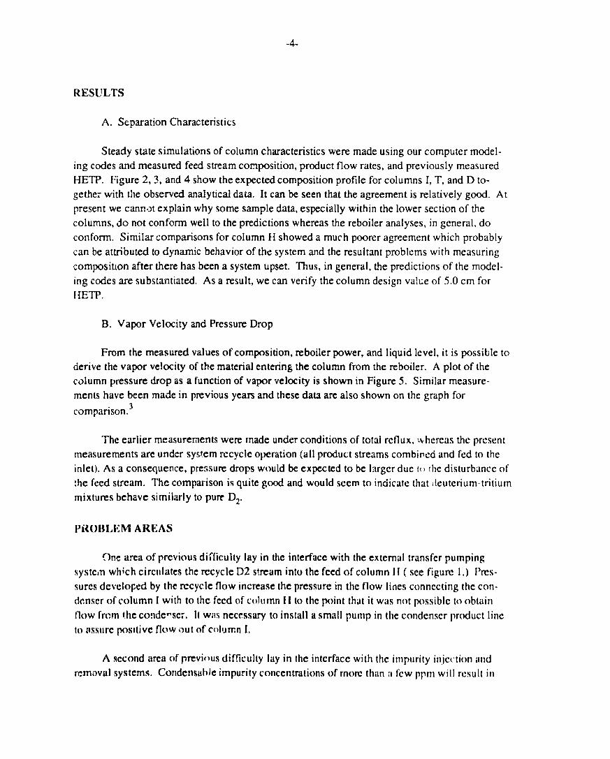
RESIJLTS
A. Separation Characteristics
Steady state simulations of column characteristics were made using our computer model-
ing codes ,and measured feed stream composition, product flow rates, and previously measured
HETP. Figure 2,3, and 4 show the expected composition profile for columns 1, T, and D to-
gethe: with the observed analytical data. It can be seen that the agreement is relatively good. At
present we cann,~t explain why some sample data, especially within the lower section of the
columns, do not conform well to the predictions whereas the reboiler analyses, in general, do
conform. Similar comparisons for column H showed a much poorer agreement which probably
can be attributed to dynamic behavior of the system and the resultant problems with measuring
compositmn after there has been a system upset. Thus, in general, the predictions of the model-
ing codes are substantiated. As a result, we can verify the column design va!~e of 5.0 cm for
f{ETP.
B, Vapor Velocity and Pressure Drop
From the measured values of composition, reboiler power, and liquid level, it is possible to
derive the vapor velocity of the material entering the column from the reboiler. A plot of the
column pressure drop as a function of vapor velocity is shown in Figure 5. Similar measure-
ments have been made in previous years and these dati are also shown on the graph for
comparison.3
The earlier measurements were made under conditions of total rcflux, :Y hercas the present
measurements are under system recycle operation (all product streams combirwci and fed to the
inlet), As a consequence, pressure drops would be expected to be lwgcr due [() the disturb~ncc of
:he feed stream. The comparison is quite good and would seem to indicate thtit ieutcrium-tritiurn
mixtures behave similarly to PUR D2.
I’iloBLEl$l AREAS
~nc itrea of previous difficulty lay in the interface with the extcmul transfer pumping
systc,n which circlllates the recycle D2 s!reitm into the feed of column 1I ( see figure 1,) f&-
surcs developed by the recycle flow increase the pressure in the flow lines connecting the con-
dcnscr of column I with to the feed of column I I to the point thtit it was not possible to obtain
flow frcrn t.hc condc~scr, It Wils necessary to install a small pump in the condcnscr product Iinc
to nssure pmlive flow out of c(dunm 1.
A second ttrca of previws difficulty lay in the intcrfiicc with the impurity itljcttitm iind
rcmowd systems. Condensuhle impurity conccntm~ions of rnorc thitn a fcw ppm will result in

-5-
rapid plugging of feed lines. Many runs were unsatisfactory because plugging of some line
occurred.
On a lesser scale, it has not always been possible to maintain desired flow from the
reboiler of column I to the feed of column T. The product lines are obviously somewhat un-
dersized. This should be correctable by the creation of a larger pressure drop between !he two
columns. While this might be accomplished by changing the operating pressure levels of the two
columns, this has proven difficult to control. Therefore it will be necessary to install a pump in
this line to create the pressure difference.
Flow meters constituw another problem area. Currently installed flowmeters have unstable
zero readings and are of such a design that zero and gain adjustments must be made within the
glovebox. Replacements are on hand and awaiting installation.
The helium refrigerator needs better stabilization. Small variatiorls in expansion engine
speed can result in changes in cooling power sllpplicd to the columns which exceed the dynamic
range of the temperature control heaters.
While the gas chromatography analytical system is satisfactory for the present experiments,
the 30-40 minute delay to receive results is not satisfactory to effect really stable control.
Furthermore, peak elution times are dependent on composition which complicates automation of
the process, A Raman spectroscopic analytical system is under development which will pcr]nit
analyses in less than one minute. In addition, such an instrument is absolute, not requiring
culibr:ltion with standard mixtures.
(X) N(;L(JSIONS
A very successful pericd of full operation of the TSTA 1SS has been complctcd. ‘1’he
results compare well with theoretical modeling results. The previously determined value of 5.0
cm for lHITP is substantiated. Pressure drors measured for pure Dz may bc used to predict
opcraticm with D-T mixtur :s.
REFERENCES
1 J R, Biu-tlit, W. Ii. Denton, and R. Il. Sherman “IIydrogcn Isotope Distiilu(ion Systcm for tlw
Tt-itiurn Systems Test Assembly”, Proc. 3rd ‘1’opl.Mtg. Tcchnok)gy of Contro!lcd Nuclear
l’usion, Santa l:C, NM, May 9-11, 1978, CC)NF-780508, VOI.2, pp 778-783,
z T. Yamimishi, 11. Yoshidti, T. Naito, S. I imta, Y. Nitrusc, RI 1. Sherman, .I.I. Ancicrson, ittld
J,R, Ilartlit, “Single Column and Two-Column 1I-II-”r Distillation Experiments at TSTA”, I:usi(m
Tcchn(dogy, in press.

-6-
3 R.H. Sherman, J.R. Bartlit. and 13.K, Veirs, “Experimental Results from H/D Distillations at
the Tritium Systems Test Assembly”, Fusion Technology 6(625)1984.
I) IS(’I,AIN1[’:N

..*
-1.-- —
‘-b’“~-’.s -
s 5 —
T
-f
s

1w
%yl
CONDENSEF
80
70
6(:)
a (:1
41:1
;Cl
Feede~c~1
10
REBOILER
t:)
Staoe Mmber
x
o

1clQ
%3
00
70
CONDENSEI
6(J
50
FEED●
40
33
20
10
REBOILER
c1
Staae Number
+ D2
❑ DT
): T2
\

1@cl
90
CONDENSEF
EC)
70
Stdae Number
FEED -
:0
~ o
10
REBOILER
(:)

12
11
10
9
B
7
6
!5
4
:,
-1.
1
cl
Prmssure Drop ( torr )
● ✍ Column I ( Total ~CflL\): - H )
cl- Column P ( Total R-flu): - D )
a- Column I ( Total Refl~(>:- H )
+- Column I ( R@cvcla Opmration - H,D.”r )
o- Column D ( RYCVCIC OD@r~tion - H.D.T )
Column T ( Rccvclm Opwatlon - H.D,T )