doepfer System A - 100 Modular Vocoder A-129 /1/2 · doepfer System A - 100 Modular Vocoder A-129...
10
doepfer System A - 100 Modular Vocoder A-129 /1/2 1 1. Introduction The A-129 /x series of modules forms a modular vocoder. ‘Vocoder’ is an abbreviation of ‘voice coder’. The basic components are an analysis section (A-129 /1) and a synthesis section (A-129 /2). Like a ring modulator, the vocoder needs two input signals: a speech element which serves as the raw material for the tonal shaping, and is patched into the analysis section; and a carrier signal, which is pat- ched via the instrument input into the synthesis sec- tion. The speech signal is chopped up and analysed in the A-129/1 module, and then combined with the carrier signal in the A-129/2 synthesis section. As a result of this procedure, the carrier signal assumes the tonal character of the speech signal, but with its own pitch maintained. Since the A-129 is a modular vocoder, and the connections between the analysis and synthesis sec- tion are external, using patch-leads, you can use this interface to patch in your choice of modules (eg. attenuator, slew limiter, CV-to-MIDI / MIDI-to-CV inter- faces,, inverter, etc.). The Five-way VC slew limiter / offset generator / attenuators (A-129 /3) and Slew controllers (A- 129/4) are particularly designed for this purpose. There’s also the possibility of connecting the frequency bands of the analysis and synthesis sections arbitra- rily, so that, for instance, a low frequency band in the speech signal can control a high frequency band in the carrier signal. The Voiced / unvoiced detector (A-129 /5) can re- cognise voiced and unvoiced sections in the speech signal, and switch the carrier signal accordingly. The A-129 /2 synthesis section can also be used as a stand-alone voltage-controlled filter bank (see chapter 6, User examples).
-
Upload
truongkhanh -
Category
Documents
-
view
221 -
download
0
Transcript of doepfer System A - 100 Modular Vocoder A-129 /1/2 · doepfer System A - 100 Modular Vocoder A-129...

doepfer System A - 100 Modular Vocoder A-129 /1/2
1
1. Introduction
The A-129 /x series of modules forms a modularvocoder. ‘Vocoder’ is an abbreviation of ‘voice coder’.
The basic components are an analysis section(A-129 /1) and a synthesis section (A-129 /2).
Like a ring modulator, the vocoder needs two inputsignals: a speech element which serves as the rawmaterial for the tonal shaping, and is patched into theanalysis section; and a carrier signal, which is pat-ched via the instrument input into the synthesis sec-tion.
The speech signal is chopped up and analysed in theA-129/1 module, and then combined with the carriersignal in the A-129/2 synthesis section. As a result ofthis procedure, the carrier signal assumes the tonalcharacter of the speech signal, but with its own pitchmaintained.
Since the A-129 is a modular vocoder, and theconnections between the analysis and synthesis sec-tion are external, using patch-leads, you can use this
interface to patch in your choice of modules (eg.attenuator, slew limiter, CV-to-MIDI / MIDI-to-CV inter-faces,, inverter, etc.).
The Five-way VC slew limiter / offset generator /attenuators (A-129 /3) and Slew controllers (A-129/4) are particularly designed for this purpose.
There’s also the possibility of connecting the frequencybands of the analysis and synthesis sections arbitra-rily, so that, for instance, a low frequency band in thespeech signal can control a high frequency band in thecarrier signal.
The Voiced / unvoiced detector (A-129 /5) can re-cognise voiced and unvoiced sections in the speechsignal, and switch the carrier signal accordingly.
The A-129 /2 synthesis section can also be used as astand-alone voltage-controlled filter bank (seechapter 6, User examples).
A-129 /1/2 Modular Vocoder System A - 100 doepfer
2
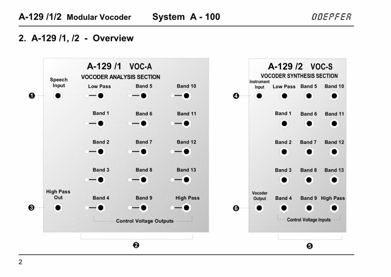
2. A-129 /1, /2 - Overview
A-129 /2 VOC-S
Band 1
Low Pass
Band 2
Band 3
Band 4
Band 5
Band 6
Band 7
Band 8
Band 9
Band 10
Band 11
Band 12
Band 13
High Pass
VOCODER SYNTHESIS SECTIONInstrument
Input
VocoderOutput
Control Voltage Inputs
A-129 /1 VOC-A
Band 1
Low Pass
Band 2
Band 3
Band 4
Band 5
Band 6
Band 7
Band 8
Band 9
Band 10
Band 11
Band 12
Band 13
High Pass
VOCODER ANALYSIS SECTIONSpeechInput
High PassOut
Control Voltage Outputs
doepfer System A - 100 Modular Vocoder A-129 /1/2
3
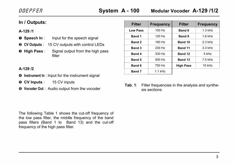
In / Outputs:
A-129 /1
! Speech In : Input for the speech signal
" CV Outputs : 15 CV outputs with control LEDs
§ High Pass : Signal output from the high pass filter
A-129 /2
$ Instrument In : Input for the instrument signal
% CV Inputs : 15 CV inputs
& Vocoder Out : Audio output from the vocoder
The following Table 1 shows the cut-off frequency ofthe low pass filter, the middle frequency of the bandpass filters (Band 1 to Band 13) and the cut-offfrequency of the high pass filter.
Tab. 1: Filter frequencies in the analysis and synthe-sis sections
Filter Frequency Filter Frequency
Low Pass 100 Hz Band 8 1.3 kHz
Band 1 120 Hz Band 9 1.6 kHz
Band 2 160 Hz Band 10 2.3 kHz
Band 3 230 Hz Band 11 3.3 kHz
Band 4 330 Hz Band 12 5 kHz
Band 5 500 Hz Band 13 7.5 kHz
Band 6 750 Hz High Pass 10 kHz
Band 7 1.1 kHz

A-129 /1/2 Modular Vocoder System A - 100 doepfer
4
3. Basic principles
The fundamental modules in this vocoder are theanalysis section A-129 /1 and the synthesis sectionA-129 /2 (see Fig. 1).
The speech signal is analysed in the A-129 /1, bybeing passed through a set of steeply sloping bandpass filters, with a low- and high- pass filter mop-ping up the bottom and top frequencies respectively.Attached to each of these filters is an envelope follo-wer, which analyses the audio signal level passingthrough, and sends a proportional voltage out of itsdedicated CV output (see below for further details).
The instrument signal is likewise sent throughanother set of steeply sloping band pass filters, and alow- and high-pass filter in the A-129 /2 synthesissection, and is split into individual frequency bands.This time, each filter has an associated VCA (voltagecontrolled amplifier), which is governed by the vol-tage present at its CV input.
In this way, each frequency band in the instrumentsignal has the dynamics of the corresponding bandfrom the speech signal superimposed onto it. Thepattern of the speech signal is thus re-constructedfrom the tonal raw material of the instrument signal.
The closer the audio spectra of the speech and carriersignals are, the more speech-like the resulting recon-struction.
Fig. 1: Block diagram of the A-129 analysis andsynthesis sections
LPF VCA
BPF 1
BPF 13
LPF
BPF 1
BPF 13
EF
EF
EF
Mix
HPF
HPF EF
Analysis A-129 /1 Synthesis A-129 /2
Speech In Instrument In
Voc.Out
HighPassOut
VCA
VCA
VCA
doepfer System A - 100 Modular Vocoder A-129 /1/2
5
H In most standard vocoders the voltage si-gnals from the analysis section are fedstraight into the synthesis section. With theA-129 modular vocoder, they are patchedexternally via 15 leads.
That means it’s possible to modify the controlvoltages by patching any sensible choice ofmodule (for instance attenuators, slew li-miters, LFO, CV-MIDI / MIDI-CV interfaces,inverters, etc.), between the analysis andsynthesis sections. Not-so-sensible choicesmay produce interesting results, too.
It’s also possible to interconnect control vol-tages to synthesis section inputs in a non-standard way, so that for instance the outputfrom a low frequency band from the speechsignal can control a high frequency elementof the carrier signal.
With a modular vocoder, the only constraintson experimentation are the limits of yourimagination (and you can also always havea look at chapter 6, User examples).
4. In / Outputs
! Speech In
Socket ! is the input to the analysis section. This iswhere the speech signal is patched in.
Don’t forget that the speech signal needs to be at thehigh level the A-100 uses internally. Plugging amicrophone directly in to the vocoder won’t work.You need to use an A-119 External Input module, intowhich you can plug a microphone or other externalsignal. Then the output of the A-119 can be patchedinto input socket ! on the analysis section.
" Low Pass • Band 1 to Band 13 • High Pass
These are the CV outputs " from the analysis sec-tion, whose voltages are determined by each filter’senvelope follower. Each CV output has an LEDconnected to it, showing the strength of the voltagegenerated.

A-129 /1/2 Modular Vocoder System A - 100 doepfer
6
§ High Pass
Socket § on the analysis section is the high passfilter output. Unlike the other sockets, this is an audiooutput, which sends out the part of the speech signalwhich the high pass filter lets through. This is mostusually added to the vocoder output, to make themodified carrier signal more speech-like still, by inclu-ding these high frequency elements of the sound.
$ Instrument In
Socket $ on the synthesis section is where you patchin the instrument that will provide the carrier signal(see below).
P Experiment with different sorts of sound forthe carrier signal, for instance
• sawtooth or square waves from a VCO,
• noise (A-118),
• digital noise (A-117).
H With an A-129 /5 voiced / un-voiced detectormodule, you can switch the carrier signaldepending on whether a speech signal ispresent.
% Low Pass • Band 1 • Band 13 • High PassThe CV inputs % on the synthesis section are wherethe control voltages from the analysis section arepatched in.
& Vocoder Out
Output & on the synthesis section is the audio outputfor the whole vocoder.

doepfer System A - 100 Modular Vocoder A-129 /1/2
7
5. User examples
Basic principles
To get the best results from the vocoder, it’s essentialto take note of the following important points:
• For professional results, the quality of the speechsignal is crucial.
If you use a cheap and cheerful microphone,connecting it up to the vocoder via the A-119 won’tguarantee good results. Any unwanted noise (rumble, airborne backgroundsounds, etc.) will greatly reduce the effectivenessof the vocoding.According to various musicians including Kraftwerk,the speech signal is easier to use if it isn’t live, buthas been taped or sampled, and thus has reliablelevels and signal-to-noise - and is repeatable.
• For early experiments, radio news stations providegood raw material, because they are nearly alwaysputting out a steady stream of human speech.
• In addition, we plan to bundle an audio cassette ofspeech with each vocoder.
• For the best results, speech and carrier signalsneed to have similar frequency spectra. A quietfemale voice, or a child’s, needs a different carriersignal compared with a low-register male voice. Ifyou use a VCO as the carrier signal, you can tuneit to find the ideal frequency.
• Basically, the instrument’s carrier signal needs tobe as overtone-rich as possible, with a dense audiospectrum. With a VCO the sawtooth output is bestsuited to the task. An exact square wave has onlyhalf as many harmonics, and triangle and sinewaves are completely unsuitable (see the notes tothe A-110 and/or A-111).
• For professional results, it’s recommended to use agraphic or parametric EQ to equalize the speechsignal to produce the most speech-like results atthe vocoder’s output. Good results can also beobtained using computer-generated speech (as onthe A-100 demo CD).

A-129 /1/2 Modular Vocoder System A - 100 doepfer
8
Using just the basic modules
Just with the A-129 /1 and A-129 /2 modules (and anA-119 external input), all the common vocoder effectscan be produced (see Fig. 2).
D First patch all the CV outputs on the analysissection to their respective CV inputs on the synthe-sis section (band 1 to 1, 2 to 2, and so on)
D Use an A-119 (External Input) to patch an audiosignal (see above, chapter 5, Basic Principles) intothe speech input socket of the analysis section atnormal A-100 operating level.
D Experiment with different audio signals for the car-rier frequency (instrument input), for instance:-
• different overtone-rich waveforms from a VCO,
• pink or coloured noise from an A-118,
• digital noise from an A-117,
• ring modulator outputs,
• two VCOs modulated in the audio range by FMor AM.
D Swap the connections between analysis and syn-thesis sections (see above).
Fig. 2: Basic vocoder schematic
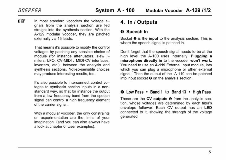
"Frequency displacement"
If instead of patching the outputs from the analysissection to their ‘proper’ respective inputs in the synthe-sis section, you swap them about instead, interestingfrequency displacements occur in the vocoder output.
Fig. 3 shows some simple variations; experimentwithall sorts of other possibilities.
A-119
LP
BP 1
BP 2
BP 12
BP 13
HP
LP
BP 1
BP 2
BP 12
BP 13
HP
A-129 /1 A-129 /2
A-138
Audio *
HighOut
SpeechIn
Instrum.In
Voc.Out
* : VCO Noise Dig. Noise Ring Mod. AM FM ...
doepfer System A - 100 Modular Vocoder A-129 /1/2
9
Fig. 3: "Frequency displacement"
"Chopped up” speech
The patch in Fig. 4 produces chopped-up speech: thevocoder chops speech up rhythmically, in time with thetrigger signals. The vocoder output is patched into aVCA, which is controlled by a rhythmical pulse from anADSR (A=0, R=0, D and S to taste). The source of thetrigger signal could be an MAQ 16/3, Schaltwerk ortrigger from a MIDI sequencer via a MIDI Interfacesuch as the A-190.
Fig. 4: Rhythmically chopped-up speech
LP
BP 1
BP 2
BP 12
BP 13
HP
LP
BP 1
BP 2
BP 12
BP 13
HP
A-129 /1 A-129 /2
SpeechIn
InstrumentIn
Voc.Out
BP 11
"Freq. up"
LP
BP 1
BP 2
BP 12
BP 13HP
LP
BP 1
BP 2
BP 12
BP 13HP
A-129 /1 A-129 /2
SpeechIn
Instrum.In
Voc.Out
BP 11
SpeechIn
InstrumentIn
"Freq. down"
LP
BP 1
BP 2
BP 12
BP 13HP
LP
BP 1
BP 2
BP 12
BP 13HP
A-129 /1 A-129 /2
Voc.Out
VCA 1
ADSR
SpeechIn
InstrumentIn
Rhythmic trigger
A-129 /1/2 Modular Vocoder System A - 100 doepfer
10
Using with the other modules ( /3, /4, /5)
While extremely usable vocoder sounds can be produ-ced with just the two basic modules, total flexibility andunlimited possibilities are offered by adding on theextra modules (A-129 /3, A-129 /4, A-129/5).
Full user instructions will be found in the modules’ ownmanuals.
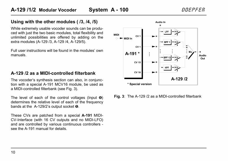
A-129 /2 as a MIDI-controlled filterbank
The vocoder’s synthesis section can also, in conjunc-tion with a special A-191 MCV16 module, be used asa MIDI-controlled filterbank (see Fig. 3).
The level of each of the control voltages (Input &)determines the relative level of each of the frequencybands at the A-129/2’s output socket %.
These CVs are patched from a special A-191 MIDI-CV-Interface (with 16 CV outputs and no MIDI-LFO)and are controlled by various continuous controllers -see the A-191 manual for details.
Fig. 3: The A-129 /2 as a MIDI-controlled filterbank
A-191 *
MIDI In
LPF VCA
BPF 1
BPF 13
Mix
HPF
Audio In
AudioOut
VCA
VCA
VCA
A-129 /2
CV 1MIDI
CV 1
CV 15
CV 16
* Special version


![Phase Vocoder Colter McQuay Phase Vocoder Structure Input x[nTs] Effect Specific Code Synthesize Output y[nTs] Analyze.](https://static.fdocuments.in/doc/165x107/56649d2d5503460f94a0489e/phase-vocoder-colter-mcquay-phase-vocoder-structure-input-xnts-effect-specific.jpg)