DOE Program April 03 - DLB fileNLC - The Next Linear Collider Project DOE Program Review April 2003...
33
NLC - The Next Linear Collider Project NLC R&D D. L. Burke DOE Annual Program Review SLAC April 9-11, 2003
Transcript of DOE Program April 03 - DLB fileNLC - The Next Linear Collider Project DOE Program Review April 2003...
NLC - The Next Linear Collider Project
NLC R&D
D. L. Burke
DOE Annual Program ReviewSLAC
April 9-11, 2003

NLC - The Next Linear Collider Project
DOE Program ReviewApril 2003
NLC R&DD. L. Burke
NLC Activities for the Past Year
• Accelerator Design centered around ILC-TRC studies.
• Technology R&D focused on the RF R&D.– Modulator, klystron, SLED-II, and structures.
• Remainder squeezed hard by budget limitations. Emphasis (in rough order of priority):– Damping Ring and ATF– Vibration and Stabilization– Ground Motion and Site Studies– Polarization – Electrons with E158, and Studies of Positron
Production
• Limited number of people active in international and national evaluations beyond the TRC – it is a growing load.
NLC - The Next Linear Collider Project
DOE Program ReviewApril 2003
NLC R&DD. L. Burke
~100 m
Positron Main Linac240-490 GeV (X)
Electron Main Linac240-490 GeV (X)
9.9 km
9.9 km
~5 km
e+ Target
2 GeV (L)Pre-DampingRing (UHF)
DampingRing
(UHF)
DampingRing
(UHF)
2 GeV (S)
136 MeV (L)
6 GeV (S)
560 m
170 m
560 m
ElectronInjector
200 m
510 m
10 m
~10 m
~100 m 0.6 GeV (X)
0.6 GeV (X)
Pre-Linac 6 GeV (S)
Pre-Linac6 GeV (S)
136 MeV (L)
RF Systems 11.424 GHz 2.856 GHz1.428 GHz0.714 GHz
8047A61110-2000
e–
e–
Hi EDetector
Low E Detector
FinalFocus
FinalFocus
~20 m
~20 m
Dump
Dump
~500 m
Compressor
Compressor
Compressor
Compressor
e+
e+
e–
(X)(S)(L)(UHF)
PositronInjector
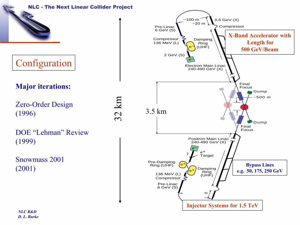
Bypass Line50 - 250 GeV
Bypass Line50 - 250 GeVBypass Lines
e.g. 50, 175, 250 GeV
X-Band Accelerator withLength for
500 GeV/Beam
32 k
m3.5 km
Configuration
Injector Systems for 1.5 TeV
Major iterations:
Zero-Order Design(1996)
DOE “Lehman” Review(1999)
Snowmass 2001(2001)

NLC - The Next Linear Collider Project
DOE Program ReviewApril 2003
NLC R&DD. L. Burke
International Linear ColliderTechnical Review Committee
• Formed in 1994 by all world-wide laboratories working in HEP.
• Technical Review in 1995 (web site).
• Charged in 2001 by ICFA to reassess technical status and establish work that remains to be done to be able to build a TeV linear collider.
Greg Loew (SLAC) Chairhttp://www.slac.stanford.edu/xorg/ilc-trc/2002/
TRC Members from NLC and JLCC. Adolphsen Yong Ho ChinK. Kubo R. PasquinelliN. Phinney T. RaubenheimerM. Ross P. TenenbaumNobu Toge P. WilsonA. Wolski K. Yokoya

NLC - The Next Linear Collider Project
DOE Program ReviewApril 2003
NLC R&DD. L. Burke
NLC/JLC(X) SLED-II Baseline Design
• Phase-I of the 8-Pack will demonstrate the feasibility of a SLED-II rf system similar to that presently in use at the NLCTA and first described in the NLC ZDR in 1996.
• This demonstration will occur in 2003.
• The NLC Collaboration, together with our JLC collaborators, presented to the world community (ILC-TRC) a SLED-II Baseline Design for an X-Band collider.

NLC - The Next Linear Collider Project
DOE Program ReviewApril 2003
NLC R&DD. L. Burke
The NLC Test Accelerator at SLACThe NLC Test Accelerator at SLAC
The NLCTA with 1.8 m accelerator structures (ca 1997).
Demonstrated ability to reach 500 GeV cms.
Accelerating gradient of 25 MV/m (loaded) with good wakefield control and energy spread.

NLC - The Next Linear Collider Project
DOE Program ReviewApril 2003
NLC R&DD. L. Burke
X-Band RF Systems
NLCTASLED-II System(ZDR 1996)
– Conventional PFN modulator
– 50 MW/1.2µs solenoid-focused klystrons
– SLED-II pulse compression
– DDS structures at 40 MV/m
X-Band TeVSLED-II System(Baseline 2002)
– Solid-state modulator
– 75 MW/1.6µsPPM-focused klystrons
– Dual mode SLED-II pulse compression
– DDS structures at 65 MV/m

NLC - The Next Linear Collider Project
DOE Program ReviewApril 2003
NLC R&DD. L. Burke
JLC/NLC Energy Reach
The NLC/JLC Stage 2 design luminosity is5 × 1033 cm-2 s-1 at 1.3 TeV cms.
CMS Energy (GeV)Site US Japan US JapanLuminosity (1033) 20 25 30 25Repetition Rate (Hz) 120 150 120 100Bunch Charge (1010)Bunches/RF PulseBunch Separation (ns)Loaded Gradient (MV/m)Injected γεx / γεy (10-8)
γεx at IP (10-8 m-rad)
γεy at IP (10-8 m-rad)
βx / βy at IP (mm)
σx / σy at IP (nm)
θx / θy at IP (nm)
σz at IP (um)ΥavePinch EnhancementBeamstrahlung δB (%)Photons per e+/e-Two Linac Length (km)
High Energy IP ParametersStage 1 Stage 2
500 1000
0.75
1.450
192
300 / 2
360
48 / 0.11
219 / 2.1
17 / 20
1.51
13.81.35.4
243 / 3.0
32 / 281100.14
300 / 2
360
413 / 0.11
1.327.6
0.75
1100.291.478.9
1921.450
Luminosity (1034)
CM
S En
ergy
(GeV
)
0 0.5 1 1.5 2 2.5 31000
1050
1100
1150
1200
1250
1300
1350
25 Bunches
192 Bunches
NLC - The Next Linear Collider Project
DOE Program ReviewApril 2003
NLC R&DD. L. Burke
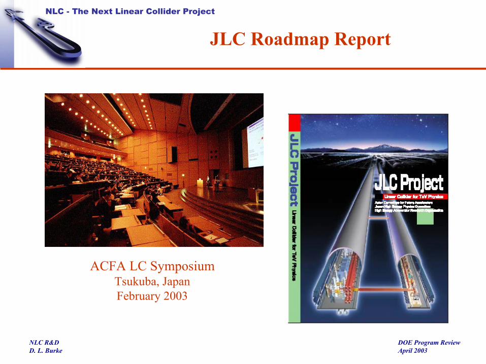
JLC Roadmap Report
ACFA LC SymposiumTsukuba, JapanFebruary 2003

NLC - The Next Linear Collider Project
DOE Program ReviewApril 2003
NLC R&DD. L. Burke
• “By the end of 2003, we hopefully should know if TESLA can reach 800 GeV at 35 MV/m.”
• “By the end of 2003, we hopefully should know if JLC/NLC can meet its main linac [1 TeV] RF system specifications.”
• “If yes, then the International Community could make a choice based on the other respective merits of these machines.”
ILC-TRC Interim ReportICFA
CERN, October 2002
NLC - The Next Linear Collider Project
DOE Program ReviewApril 2003
NLC R&DD. L. Burke
• “Test of complete accelerator structure at design gradient with detuning and damping, including study of breakdown and dark current.”
• “Demonstration of SLED-II pulse compression system at design power level.”
JLC(X)/NLC Level I R&D Requirements (R1)

NLC - The Next Linear Collider Project
DOE Program ReviewApril 2003
NLC R&DD. L. Burke
• After improvements to the rf at NLCTA in 2000, realized the 1.8 m long structures were being damaged during processing and would not meet performance at 65 MV/m.
• Launched aggressive R&D program– Build and test traveling wave structures and standing wave structures.– Improve structure handling, cleaning and baking methods.– Study characteristics of rf breakdown in structures, cavities and waveguides.
Have tested 20 structures made from a total of approximately 1000 cells.Over 10,000 hr operation at 60 Hz. → 109 rf pulses; a total of ~ 105 rf breakdown events.
High-Gradient R&D
T-Series Structures – 50 cm long low group velocity structures with high shunt impedance.

NLC - The Next Linear Collider Project
DOE Program ReviewApril 2003
NLC R&DD. L. Burke
RF Pulse Heating
TM01 Mode Launcher
WC90WR90
RFNew Mode-Converter (MC)
Coupler Design
Pulse heating less than 3° C.
SEM picture of input matching iris.Pulse heating in excess of 100° C.
RF RF
T53VG3(Original Coupler Design)

NLC - The Next Linear Collider Project
DOE Program ReviewApril 2003
NLC R&DD. L. Burke
Stru
ctur
e G
radi
ent (
MV
/m)
Time with RF On (hr)
T53VG3MC Processing History(Low-Temperature Couplers)
1Trip per25 Hrs
400 ns Pulse Width
1 Trip per 25 Hrs
NLC/JLC Trip Goal:Less than 1 per 10 Hrs at 65 MV/m
No Phase Change (< 0.5°)
Onset of “Spitfests”

NLC - The Next Linear Collider Project
DOE Program ReviewApril 2003
NLC R&DD. L. Burke
H-Series Structures
• The T-Series design cannot be used in the NLC/JLC.
– The average iris radius, <a/λ> is smaller (0.13) than desired (0.17-0.18), yielding a transverse wakefield 3 times larger than considered acceptable.
• Now moved to designs with <a/λ> = 0.17-0.18 (called the H-Series because the phase advance per cell is 150°).
Five H-Series structures have been built and tested so far:• H90VG5: High-temperature couplers prevented full processing.
• H60VG3: High-temperature couplers – body breakdown rate OK at 65 MV/m.
• FXB002: First H60VG3 produced by Fermilab – no hydrogen preprocessing, and would nothigh-gradient process above 70 MV/m.
• H90VG3 and H60VG3_6C presently under test.
Six full-featured DDS cells.

NLC - The Next Linear Collider Project
DOE Program ReviewApril 2003
NLC R&DD. L. Burke
H90VG3 Breakdown Rates
5 5 6 0 6 5 7 0 7 5 8 0 8 5 9 01 0
- 1
1 00
1 01
Bre
akdo
wn
rate
per
hou
r
A v e ra g e g ra d ie n t
H 9 0 v g 3 N
4 0 0 n s2 4 0 n s1 0 0 n s
Slope ~ 8 MV/m / decade
Bre
akdo
wn
Rat
e (p
er h
r)
Data Near End of Run Structure Gradient (MV/m)
JLC/NLCGoal

NLC - The Next Linear Collider Project
DOE Program ReviewApril 2003
NLC R&DD. L. Burke
Breakdown Statistics for H60VG3(6C)(65 MV/m, 400 ns)
Num
ber o
f Trip
s
Trip
s per
Hou
r
0 2 4 6 8 1 0 1 2 1 40
0 . 1
0 . 2
0 . 3
0 . 4
0 . 5
0 . 6
0 . 7
0 . 8
Days
Goal
Mean
0 5 1 0 1 5 2 0 2 5 3 00
5
1 0
1 5
2 0
2 5
3 0
3 5
4 0
4 5
Time Between Trips (Minutes)
(Times > 30 Plotted at 30)
A two-week run produces 80 breakdowns.
To date have 900 hrs of rf on this structure, and continuing to run ….
NLC - The Next Linear Collider Project
DOE Program ReviewApril 2003
NLC R&DD. L. Burke
• H60VG3_6C performs acceptably at 65 MV/m, but we think we can do better.
• To improve rf efficiency and provide more operating overhead, we will focus on the a/λ = .17 version of this structure (H60VG3S17).
• A first test structure of this design is being built without damping slots.
• The main goal for the next year is to have eight DDS structures of this design operating at 65 MV/m in the NLCTA linac with power provided by the SLED-II, and to accumulate ~ 2000 hours of high-gradient operation.
→ Next slides.Fermilab and KEK will build structures for this “TRC R2” demonstration.
• We will continue to study two alternate possibilities that might provide dramatically better gradients:
Standing-wave structures with low pulse temperature rise couplers.Structures with Mo and W irises (built by CERN).
High-Gradient Plans

NLC - The Next Linear Collider Project
DOE Program ReviewApril 2003
NLC R&DD. L. Burke
NLC/JLC SLED-II Baseline Test
NLCTA Housing
Solid-State Modulator
Solenoid-Focused Klystrons (to be replaced with PPM tubes).
Dual-Mode SLED-II
Our Japanese colleagues are full partners in this plan.
KEK will provide klystrons, pulse-handling, and accelerator structures, and will participate in testing.
Goal is to generate an RF pulse (450 MW 400 nsec) for a girder (4.8 meters) of high-gradient structures (65 MV/m).
NLC - The Next Linear Collider Project
DOE Program ReviewApril 2003
NLC R&DD. L. Burke
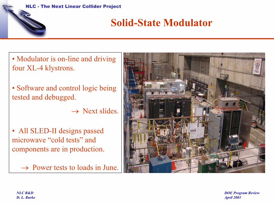
Solid-State Modulator
• Modulator is on-line and driving four XL-4 klystrons.
• Software and control logic being tested and debugged.
→ Next slides.
• All SLED-II designs passed microwave “cold tests” and components are in production.
→ Power tests to loads in June.

NLC - The Next Linear Collider Project
DOE Program ReviewApril 2003
NLC R&DD. L. Burke
Solid State Modulator Commissioning
500 ns/div
Voltage pulse flattened by delayed firing sequence of boards in the IGBT stack.
400 kV
250 A
1 >
2 >4 >
1) Trace 1: 2.5 VOL 500 nSEC 2) Trace 2: 50 kVOL 500 nSEC 4) Trace 5: 500 VOL 500 nSEC
w/ 17/74 delayed trig @400nS, 500nS and 1200nS4/7/03
NLC - The Next Linear Collider Project
DOE Program ReviewApril 2003
NLC R&DD. L. Burke
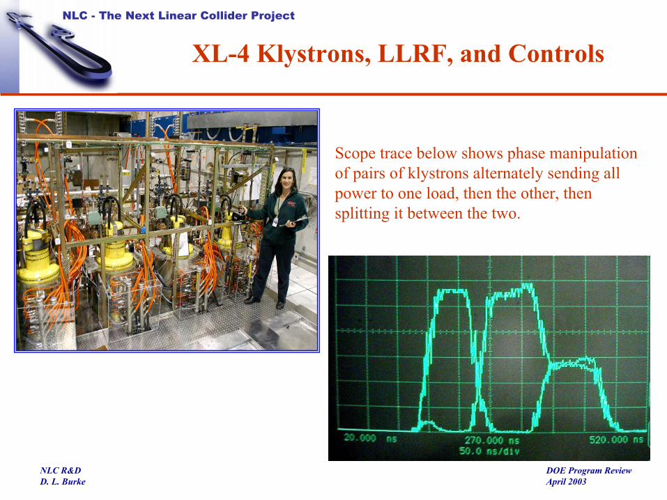
XL-4 Klystrons, LLRF, and Controls
Scope trace below shows phase manipulation of pairs of klystrons alternately sending all power to one load, then the other, then splitting it between the two.

NLC - The Next Linear Collider Project
DOE Program ReviewApril 2003
NLC R&DD. L. Burke
SLED-II Components
Directional Coupler
Cross Potent Body
Mounting Test of Delay Lines
NLC - The Next Linear Collider Project
DOE Program ReviewApril 2003
NLC R&DD. L. Burke
From SLED
3 dB
3 dB
3 dB
3 dB
3 dB
3 dB
3 dB
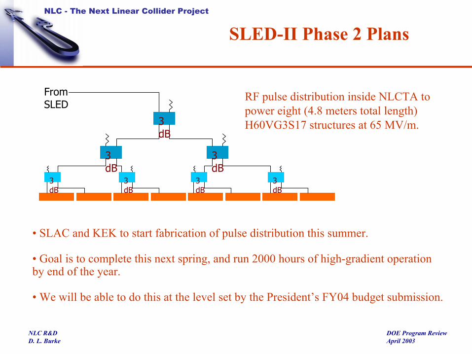
SLED-II Phase 2 Plans
• SLAC and KEK to start fabrication of pulse distribution this summer.
• Goal is to complete this next spring, and run 2000 hours of high-gradient operation by end of the year.
• We will be able to do this at the level set by the President’s FY04 budget submission.
RF pulse distribution inside NLCTA to power eight (4.8 meters total length) H60VG3S17 structures at 65 MV/m.

NLC - The Next Linear Collider Project
DOE Program ReviewApril 2003
NLC R&DD. L. Burke
RF R&D Activities and Plans Through 2004
NLC - The Next Linear Collider Project
DOE Program ReviewApril 2003
NLC R&DD. L. Burke
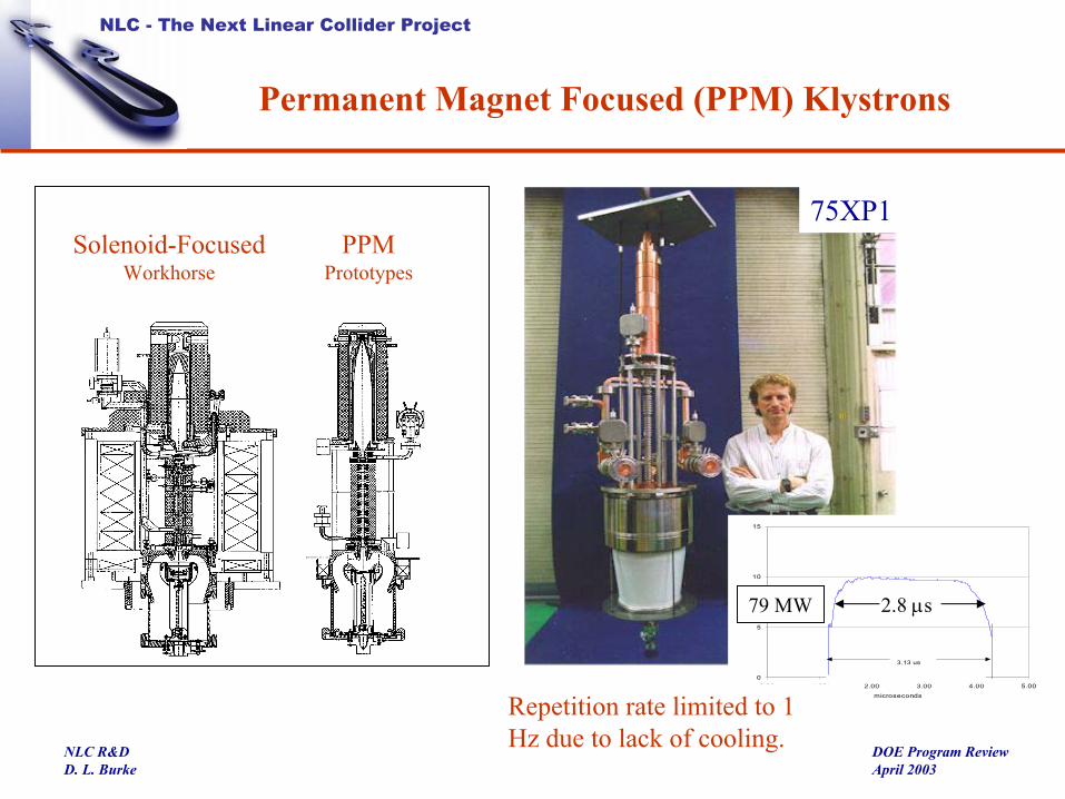
Permanent Magnet Focused (PPM) Klystrons
Solenoid-FocusedWorkhorse
PPMPrototypes
75XP1
0
5
10
15
0.00 1.00 2.00 3.00 4.00 5.00
microseconds
dBm
3.13 us
2.8 µs79 MW
Repetition rate limited to 1 Hz due to lack of cooling.

NLC - The Next Linear Collider Project
DOE Program ReviewApril 2003
NLC R&DD. L. Burke
High-Rep Rate PPM Klystrons
SLAC XP3-3 (Rebuild)Starting tests this week.
XP-4 design nearing completion.
KEK/Toshiba PPM2
Previously achieved 70 MW at 1.5 µs at KEK (limited by modulator performance), and is now under test at SLAC.
PPM4 beginning test at KEK.
NLC - The Next Linear Collider Project
DOE Program ReviewApril 2003
NLC R&DD. L. Burke
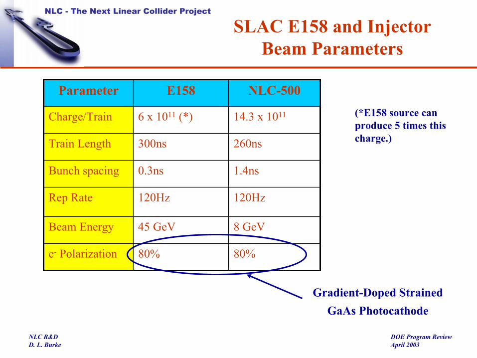
80%80%e- Polarization
14.3 x 10116 x 1011 (*)Charge/Train
8 GeV45 GeVBeam Energy
120Hz120HzRep Rate
1.4ns0.3nsBunch spacing
260ns300nsTrain Length
NLC-500E158Parameter
SLAC E158 and InjectorBeam Parameters
(*E158 source can produce 5 times this charge.)
Gradient-Doped Strained GaAs Photocathode

NLC - The Next Linear Collider Project
DOE Program ReviewApril 2003
NLC R&DD. L. Burke
ATF Damping Ring at KEKATF Damping Ring at KEK
SLAC and KEK physicists survey the ring.
“Laser Wire”
Issues Under Study • Intra-Beam Scattering• Electron Cloud• Trapped Ions
ATF
ALS
2003•
NLC - The Next Linear Collider Project
DOE Program ReviewApril 2003
NLC R&DD. L. Burke
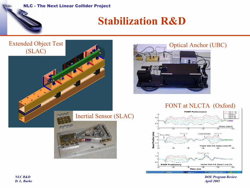
Stabilization R&D
FONT at NLCTA (Oxford)
Optical Anchor (UBC)Extended Object Test(SLAC)
Inertial Sensor (SLAC)

NLC - The Next Linear Collider Project
DOE Program ReviewApril 2003
NLC R&DD. L. Burke
U.S. Linear Collider Steering Committee
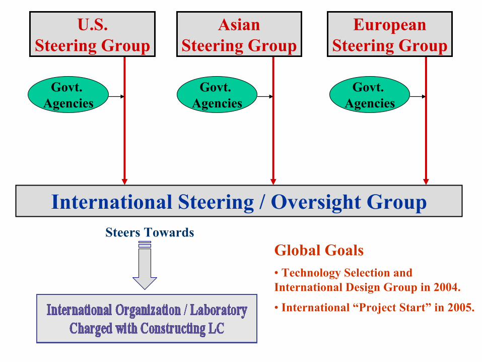
Steers Towards
International Steering / Oversight Group
Govt. Agencies
Govt. Agencies
Govt. Agencies
U.S.Steering Group
AsianSteering Group
EuropeanSteering Group
Global Goals• Technology Selection and International Design Group in 2004.
• International “Project Start” in 2005.
NLC - The Next Linear Collider Project
DOE Program ReviewApril 2003
NLC R&DD. L. Burke
NLC Activities for the Next Year
• Accelerator Design centered around USLCSG evaluation. This is expanding to include more on cost and schedule, reliability modeling, and risk assessment, and will include work on the cold option.
• Technology R&D will stay focused on the RF R&D.– SLED-II driving 4.8 meter girder of structures at 50 MV/m loaded gradient –
a 250 MeV accelerator operated for ~ 2000 hours.– Prototype modulator “2-Pack” with next-generation IGBT switches, and PPM
klystron prototypes (XP4-1 and 2).
• Remainder will still be squeezed hard by budget limitations, and priority will remain the same.– Damping Ring and ATF - nanometer BPM development.– Vibration and Stabilization - extended girder studies.– Ground Motion and Site Studies– Polarization – Studies of Positron Production