DOE-HDBK-1129-99; DOE Handbook Tritium Handling and Safe ......
146
TS NOT MEASUREMENT SENSITIVE DOE-HDBK-1129-99 March 1999 DOE HANDBOOK TRITIUM HANDLING AND SAFE STORAGE U.S. Department of Energy AREA SAFT Washington, D.C. 20585 DISTRIBUTION STATEMENT A. Approved for public release; distribution is unlimited.
Transcript of DOE-HDBK-1129-99; DOE Handbook Tritium Handling and Safe ......
TS
NOT MEASUREMENTSENSITIVE
DOE-HDBK-1129-99March 1999
DOE HANDBOOK
TRITIUM HANDLING AND SAFE STORAGE
U.S. Department of Energy AREA SAFTWashington, D.C. 20585
DISTRIBUTION STATEMENT A. Approved for public release; distribution is unlimited.

This document has been reproduced from the best available copy.
Available to DOE and DOE contractors from ES&H Technical InformationServices, U.S. Department of Energy, (800) 473-4375, fax: (301) 903-9823.
Available to the public from the U.S. Department of Commerce, TechnologyAdministration, National Technical Information Service, Springfield, VA 22161;(703) 605-6000.
DOE-HDBK-1129-99
iii
TABLE OF CONTENTS
SECTION PAGEFOREWORD.............................................................................................................................viiACRONYMS ..............................................................................................................................ix1.0 INTRODUCTION.................................................................................................................. 1
1.1 Purpose ............................................................................................................................ 11.2 Scope ............................................................................................................................... 11.3 Applicability....................................................................................................................... 11.4 Referenced Material for Further Information...................................................................... 2
2.0 TRITIUM............................................................................................................................... 32.1 Radioactive Properties...................................................................................................... 32.2 Physical Properties ........................................................................................................... 42.3 Chemical Properties.......................................................................................................... 52.4 Biological Properties ......................................................................................................... 52.5 Preferred Forms................................................................................................................ 7
3.0 BASIC TRITIUM REGULATORY INFORMATION.............................................................. 173.1 Tritium Accountability...................................................................................................... 173.2 Tritium Safeguards and Security ..................................................................................... 213.3 Tritium Facility Safety Analysis and Regulatory Quantity Limits ...................................... 223.4 Radiological Materials Quantity Limits............................................................................. 273.5 Tritium Unpackaging, Handling, and Packaging Areas, Quantity Limits .......................... 283.6 Tritium Waste Collection and Waste Packaging Area, Quantity Limits ............................ 283.7 Tritium Focus Group (TFG)............................................................................................. 28
4.0 FACILITY DESIGN............................................................................................................. 284.1 Tritium System Philosophy.............................................................................................. 284.2 Building Ventilation System............................................................................................. 384.3 Chilled Water System ..................................................................................................... 404.4 Seismic and Wind Design and Evaluation of Structures and Facilities ............................ 404.5 Other Design Considerations .......................................................................................... 424.6 Lessons Learned ............................................................................................................ 43
5.0 DESIGN OF EQUIPMENT.................................................................................................. 465.1 Material Compatibility...................................................................................................... 475.2 First Wall Design............................................................................................................. 525.3 Secondary Wall Design................................................................................................... 535.4 Cleanup System Design ................................................................................................. 535.5 Storage System Design .................................................................................................. 535.6 Surveillance and Maintenance ........................................................................................ 555.7 Seismic Considerations .................................................................................................. 555.8 Fire Scenarios................................................................................................................. 605.9 Instrumentation ............................................................................................................... 60
6.0 TRITIUM PURCHASING AND RECEIVING ....................................................................... 656.1 Shipping Packages ......................................................................................................... 656.2 Product Containers ......................................................................................................... 666.3 Valve Container Operations ............................................................................................ 68
DOE-HDBK-1129-99
iv
6.4 Receiving Tritium ............................................................................................................ 726.5 Storage of Packaged Nuclear Materials .......................................................................... 72
7.0 PACKAGING AND TRANSPORTATION............................................................................ 737.1 General Administrative Packaging and Transport Requirements .................................... 737.2 Selection of Proper Packaging........................................................................................ 737.3 Package Loading and Preparation for Shipment ............................................................. 797.4 Documentation and Records........................................................................................... 807.5 Quality Assurance/Control Requirements ....................................................................... 84
8.0 TRITIUM WASTE MANAGEMENT..................................................................................... 858.1 Approved Limits for the Release of Contaminated Materials and Property Containing
Residual Radioactive...................................................................................................... 868.2 Waste Characterization................................................................................................... 938.3 Waste Packaging............................................................................................................ 988.4 Waste Shipping............................................................................................................... 99
FIGURES:FIGURE 2-1. Rate of tritium decay of one mole of tritium ........................................................... 4FIGURE 2-2. Pressure versus time in a container of tritium........................................................ 4FIGURE 2-3. Comparison of aqueous tritium levels found in the nuclear industry ...................... 9FIGURE 2-4. Dissociation pressure for uranium, hydride, deuteride, and tritide ....................... 11FIGURE 2-5. Plot of a good fit curve for the dissociation pressure of uranium hydride,
deuteride, and tritide ........................................................................................... 11FIGURE 2-6. Dissociation pressure of palladium hydride and deuteride................................... 13FIGURE 4-1. Tritium facility single-pass ventilation system...................................................... 30FIGURE 4-2. Secondary containment ...................................................................................... 32FIGURE 4-3. Secondary confinement ...................................................................................... 32FIGURE 4-4. Building confinement system .............................................................................. 33FIGURE 4-5. Typical gas-to-water tritium removal system flow schematic ............................... 34FIGURE 4-6. Confinement volume cleanup rate as a function of system time constant, F/V,
assuming an exponential dilution rate................................................................. 36FIGURE 5-1. Development of the seismic equipment list ......................................................... 58FIGURE 5-2. Comparison of seismic capacity spectra to seismic demand spectra .................. 59FIGURE 6-1. Use of double valve container ............................................................................. 69FIGURE 6-2. Purge ports and isolation valves ......................................................................... 70FIGURE 8-1. Ultimate disposition of tritiated material.............................................................. 97
TABLES:TABLE 2-1. Derived air concentrations for tritium and tritiated water.......................................... 6TABLE 2-2. ICRP-71 dose conversion factors for inhalation of tritiated particulates ................... 7TABLE 2-3. Dissociation pressure equation parameters for uranium hydride, deuteride,
and tritide ............................................................................................................. 10TABLE 2-4. Dissociation pressure equation parameters for palladium hydride and deuteride .. 13TABLE 3-1. EPA maximum contaminant level for tritium .......................................................... 20TABLE 3-2. Worst-case doses in rem resulting from release of 1 Ci of tritium.......................... 24TABLE 5-1. Representative equipment found in tritium facilities............................................... 57TABLE 5-2. SAM technical specifications................................................................................. 65TABLE 7-1. Allowable quantities of tritium per 49 CFR 173...................................................... 76

DOE-HDBK-1129-99
v
APPENDICES:APPENDIX A: USEFUL NUMERICAL VALUESAPPENDIX B: DEFINITIONSAPPENDIX C: ASSAY METHODSAPPENDIX D: CONTAMINATION AND SURFACE ACTIVITY THRESHOLDSAPPENDIX E: RESOURCES USED IN WRITING THIS HANDBOOKAPPENDIX F: TRITIUM FOCUS GROUP CHARTER

DOE-HDBK-1129-99
vi
This page is intentionally blank.

DOE-HDBK-1129-99
vii
FOREWORD
Tritium handling practices have evolved over several decades at Department of Energy tritiumfacilities. The objective has been to accomplish required tritium work while minimizing andcontrolling the exposure of workers, the public, and the environment from tritium. Thisdocument provides guidance for the handling, storing and shipping of tritium. Literaturereferences furnish information current through mid-1998.
This Department of Energy Handbook is approved for use by all DOE components and theircontractors. There are no requirements generated by this document, only requirementsreferenced from other sources.
The principal authors, Bill Weaver of DOE-EH and William R. Wall of LLNL and SNLL, wish toacknowledge the contributions of Jim Bachmaier and Bill Fortune of DOE-EH; Elliot Clark andBob Rabun of WSRC; Ray Hahn of Envirocare; Ron Hafner, Gary Mansfield, Mark Mintz,Robert C. Murray, and Stanley C. Sommer of LLNL; Tobin Oruch and Diana West of LANL;Mike Rogers and Paul Lamberger of Mound; Nazir Kherani of Ontario Hydro; Keith Rule ofPPPL; Jeff Paynter of E2 Consulting Engineers; Phil Grant and Barbara Kneece of Wastren;and Jimmy Myers and Elaine Merchant of Parallax, Inc.

DOE-HDBK-1129-99
viii
This page is intentionally blank.

DOE-HDBK-1129-99
ix
ACRONYMS
AEA Atomic Energy Act of 1954ALARA As Low As Reasonably AchievableALI Annual Level of IntakeAPT Accelerator Production of TritiumASCE American Society of Civil EngineersASME American Society of Mechanical EngineersANSI American National Standards InstituteCEDE Committed Effective Dose EquivalentCERCLA Comprehensive Environmental Response, Compensation, and Liability ActCLWR Commercial Light Water ReactorCoC Certificate of ComplianceCWA Clean Water ActD&D Decontamination and DecommissioningDAC Derived Air ConcentrationDBA Design Basis AccidentDBE Design Basis EarthquakeDCF Dose Conversion FactorDCG Derived Concentration GuideDNFSB Defense Nuclear Facilities Safety BoardDOE U.S. Department of EnergyDOT U.S. Department of TransportationEDL Economic Discard LimitEH Office of Environment, Safety and HealthEPCRA Emergency Planning and Community Right-to-Know ActEPDM Ethylene Propylene Diene MonomerEPA Environmental Protection AgencyEIS Environmental Impact StatementFCA Fire Control AreaFDTAS Field Deployable Tritium Analysis SystemFY Fiscal YearHDPE High Density PolyethyleneHIVES Highly Invulnerable Encased SafeHMR Hazardous Material RegulationsHSV Hydride Storage VesselHSWA Hazardous and Solid Waste AmendmentsHTP Hydride Transport VesselHTV Hydride Transport VesselHVAC Heating, Ventilation, and Air ConditioningIAEA International Atomic Energy AgencyICRP International Commission on Radiological ProtectionISM Integrated Safety ManagementkeV Kilo-Electron-VoltsLANL Los Alamos National LaboratoryLLNL Lawrence Livermore National LaboratoryLDR Land Disposal RestrictionLSA Low Specific ActivityLDPE Low-Density Polyethylene
DOE-HDBK-1129-99
x
LLD Lower Limit of DetectionLLW Low-Level WastemCi MillicurieMCL Maximum Contaminant LevelMEI Maximally Exposed Individualmm Millimetersmrem MilliremNFPA National Fire Protection AssociationNPDWR National Primary Drinking Water RegulationNPH Natural Phenomena HazardNRC U.S. Nuclear Regulatory CommissionPC Performance CategoryPCB Polychlorinated BiphenylPMR Palladium Membrane ReactorPPPL Princeton Plasma Physics Laboratorypsia pounds per square inch absolutepsig pounds per square inch gaugePTFE PolytetrafluoroethylenePVC Polyvinyl ChloridePV Product VesselRCRA Resource Conservation and Recovery ActRMA Radioactive Materials AreaRTF Replacement Tritium FacilitySAES Societá Apparecchi Elettrici e ScientificiSAM Surface Activity MonitorSAR Safety Analysis ReportSCO Surface Contaminated ObjectSEL Seismic Equipment ListSEP Seismic Evaluation ProcedureSMT Stable Metal TritideSNL Sandia National LaboratorySNLL Sandia National Laboratory, LivermoreSNM Special Nuclear MaterialSRS Savannah River SiteSSCs Structures, Systems, and ComponentsTRL Tritium Research Laboratory, Sandia National LaboratoryTSD Treatment, Storage, and DisposalTSR Technical Safety RequirementUBC Uniform Building CodeUHMWPE Ultra-High-Molecular-Weight PolyethyleneWETF Weapons Engineering Tritium Facility, Los Alamos National LaboratoryWSRC Westinghouse Savannah River Company
DOE-HDBK-1129-99
1
1.0 INTRODUCTION
There are several tritium-handling publications, including International Atomic Energy Agency(IAEA) Technical Report Series, Number 324, “Safe Handling of Tritium,” published in 1991; andU.S. Department of Energy (DOE) publications, most notably DOE Handbook, DOE-HDBK-1079-94, “Primer on Tritium Safe Handling Practices,” published in 1994. The DOE Handbook wasdeveloped as an educational supplement and reference for operations and maintenancepersonnel. Most of the tritium publications are written from a radiological protection perspective.This handbook provides more extensive guidance and advice on the full range of tritiumoperations.
1.1 Purpose
This handbook can be used by personnel involved in the full range of tritium handling from receiptto ultimate disposal. Compliance issues are addressed at each stage of handling. This handbookcan also be used as a reference for those individuals involved in real time determination ofbounding doses resulting from inadvertent tritium releases.
1.2 Scope
This handbook provides useful information for establishing processes and procedures for thereceipt, storage, assay, handling, packaging, and shipping of tritium and tritiated wastes. Itincludes discussions and advice on compliance-based issues and adds insight to those areas thatcurrently possess unclear DOE guidance. It is intended to be a “living document,” being revisedperiodically. For example, planning for and implementing contamination control as part of normaloperation and maintenance activities is an important function in any tritium facility. The bestpractices from around the complex are presently being accumulated for inclusion in the nextrevision of this Handbook. Likewise, it is planned that the next revision will include a section ontraining issues for tritium operators and maintenance personnel.
1.3 Applicability
DOE facilities range from small radiological facilities engaged in operations using a few millicuries(mCi) up to 16,000 Ci of tritium; to large-scale facilities referred to as Non-Reactor NuclearFacilities, using greater than 16,000 Ci (1.6 grams) of tritium. Guidance in this handbook isapplicable to any scale of operations.
Some sections of this handbook resulted from consensus agreement between DOE’s TritiumFocus Group members and the authors, representing the views of the Office of Nuclear andFacility Safety, EH-3, an organization within the Office of Environment, Safety and Health at DOEHeadquarters. Other sections are strictly the viewpoint of the Office of Nuclear and Facility Safety.This office solicits comments and active discussion of the handbook content in order to improvethe handbook on its next revision.
DOE-HDBK-1129-99
2
1.4 Referenced Material for Further Information
• DOE O 420.1, “Facility Safety”• DOE G 420.1/B-0, “Implementation Guide for use with DOE Orders 420.1 and 440.1, Fire
Safety Program”• DOE G 420.1-X, “Implementation Guide for Non-Reactor Nuclear Safety Design Criteria and
Explosives”• DOE G 420.1-Y, “Implementation Guide for the Mitigation of Natural Phenomena Hazards for
Non-Nuclear Facilities”• DOE O 435.1, “Radioactive Waste Management”• DOE P 450.4, “Safety Management System Policy”• DOE G 450.4-1, Volumes 1 and 2, “Integrated Safety Management System Guide, Revision 0”• DOE O 460.1A, “Packaging and Transportation Safety”• DOE G 460.1-1, “Implementation Guide for Use with DOE O 460.1A”• DOE O 460.2, “Departmental Materials Transportation and Packaging Management”• DOE M 474.1-2, “Manual for Nuclear Materials Management and Safeguards System
Reporting and Data Submission”• DOE Order 5400.5, “Radiation Protection of the Public and Environment”• DOE Order 5480.23, “Nuclear Safety Analysis Reports”• DOE-EM-STD-5502-94, “Hazard Baseline Documentation”• DOE Order 5610.12, “Packaging and Transportation of Nuclear Components”• DOE Order 5633.3B, “Control and Accountability of Nuclear Materials”• DOE Order 5820.2A, “Radioactive Waste Management”• DOE-STD-1020-94, “Natural Phenomena Hazards Design and Evaluation Criteria for
Department of Energy Facilities,” including Change Notice 1, January 1996• DOE-STD-1021-93, “Natural Phenomena Hazards Performance Categorization Guidelines for
Systems, Structures, and Components,” including Change Notice 1, January 1996• DOE-STD-1022-94, “Natural Phenomena Hazards Characterization Criteria,” including Change
Notice 1, January 1996• DOE-STD-1023-95, “Natural Phenomena Hazards Assessment Criteria,” including Change
Notice 1, January 1996• DOE-STD-1027-92, “Hazard Categorization and Accident Analysis Techniques for Compliance
with DOE Order 5480.23, Nuclear Safety Analysis Reports,” including Change Notice 1,September 1997
• DOE-STD-1120-98, “Integration of Environment, Safety, and Health into Facility DispositionActivities”
• DOE-STD-3009-94, “Preparation Guide for U.S. DOE Nonreactor Nuclear Facility SafetyAnalysis Reports”
• DOE-HDBK-1105-96, “Radiological Training for Tritium Facilities”• DOE-HDBK-1079-94, “Primer on Tritium Safe Handling Practices”• DOE-HDBK-3010-94, “Airborne Release Fraction/Rates and Respirable Fractions for
Nonreactor Nuclear Facilities”• DOE/TIC-11268, “A Manual for the Prediction of Blast and Fragment Loading of Structures”• ANS 14-1994, “Internal Dosimetry Standards for Tritium”• ASCE 7-95, “Minimum Design Loads for Buildings and Other Structures”• 10 CFR 20, “Standards for Protection Against Radiation”• 10 CFR 71, “Packaging and Transportation of Radioactive Material”• 10 CFR 830, “Nuclear Safety Management”
DOE-HDBK-1129-99
3
• 10 CFR 835, “Occupational Radiation Protection”• 40 CFR 261, “Identification and Listing of Hazardous Waste”• 40 CFR 262, “Standards Applicable to Generators of Hazardous Waste”• 40 CFR 302.4, “Designation of Hazardous Substances”• 49 CFR 172, “Hazardous Materials Table, Special Provisions, Hazardous Materials
Communications, Emergency Response Information, and Training Requirements”• 49 CFR 173, “Shippers – General Requirements for Shipments and Packagings”• 49 CFR 177, “Carriage by Public Highway”• 49 CFR 178, “Specifications for Packaging”• 62 FR 62079, Joint NRC/EPA Guidance on Testing Requirements for Mixed Radioactive and
Hazardous Waste, November 20, 1997• IAEA Technical Report Series #324, “Safe Handling of Tritium”• IAEA-SM-181/19, “Estimates of Dry Deposition and Plume Depletion over Forests and
Grassland”• ISO 7503-2, “Evaluation of Surface Contamination – Part 2: Tritium Surface Contamination”• Office of Nuclear and Facility Safety Technical Notice 94-01, “Guidelines for Valves in Tritium
Service”• OSWER 9928.4-03, Waste Analysis at Facilities that Generate, Treat, Store, and Dispose of
Hazardous Wastes: A Guidance Manual, April 1994• Westinghouse Savannah River Company, WSRC-TR-94-0596, Titanium for Long Term Tritium
Storage (U), December 1994.
2.0 TRITIUM
Isotopes are elements that have the same atomic number (same number of protons in the nucleus)but of different atomic mass (total number of protons plus neutrons in the nucleus). There arethree isotopes of hydrogen. Ordinary hydrogen, referred to as protium (1H
1, atomic mass of 1), isthe most abundant element in the universe and has one proton in the nucleus. Heavy hydrogen,referred to as deuterium (1H
2, or D, atomic mass of 2), makes up about 0.015 percent of thehydrogen, and has one proton and one neutron in the nucleus. Radioactive hydrogen, referred toas tritium (1H
3, or T, atomic mass of 3), has one proton and two neutrons in the nucleus. Refer toDOE-HDBK-1079-94 and the IAEA Guide on Safe Handling of Tritium for basic information ontritium, its properties, and compounds.
2.1 Radioactive Properties
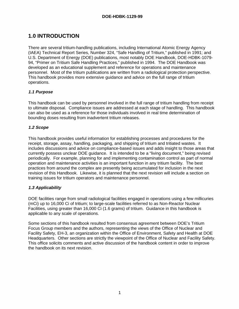
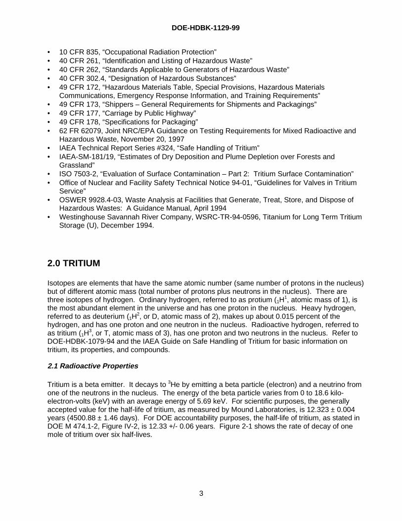
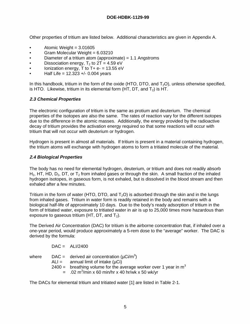
Tritium is a beta emitter. It decays to 3He by emitting a beta particle (electron) and a neutrino fromone of the neutrons in the nucleus. The energy of the beta particle varies from 0 to 18.6 kilo-electron-volts (keV) with an average energy of 5.69 keV. For scientific purposes, the generallyaccepted value for the half-life of tritium, as measured by Mound Laboratories, is 12.323 ± 0.004years (4500.88 ± 1.46 days). For DOE accountability purposes, the half-life of tritium, as stated inDOE M 474.1-2, Figure IV-2, is 12.33 +/- 0.06 years. Figure 2-1 shows the rate of decay of onemole of tritium over six half-lives.
DOE-HDBK-1129-99
4
FIGURE 2-1. Rate of tritium decay of one mole of tritium
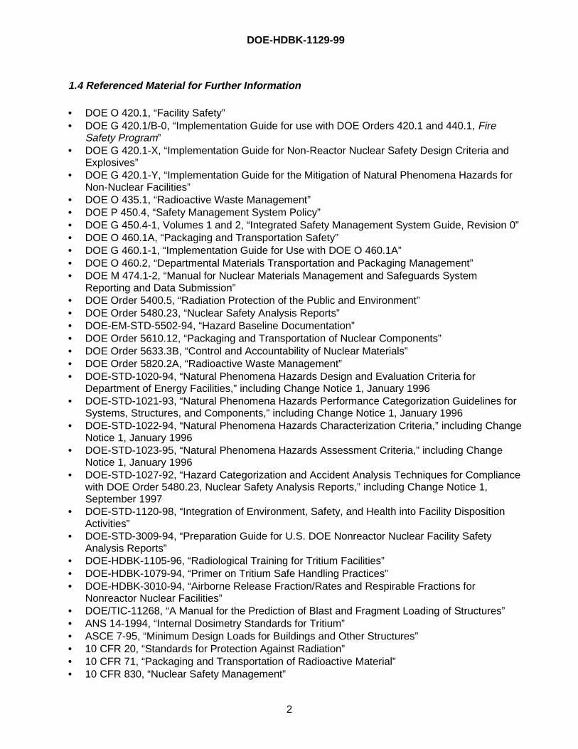
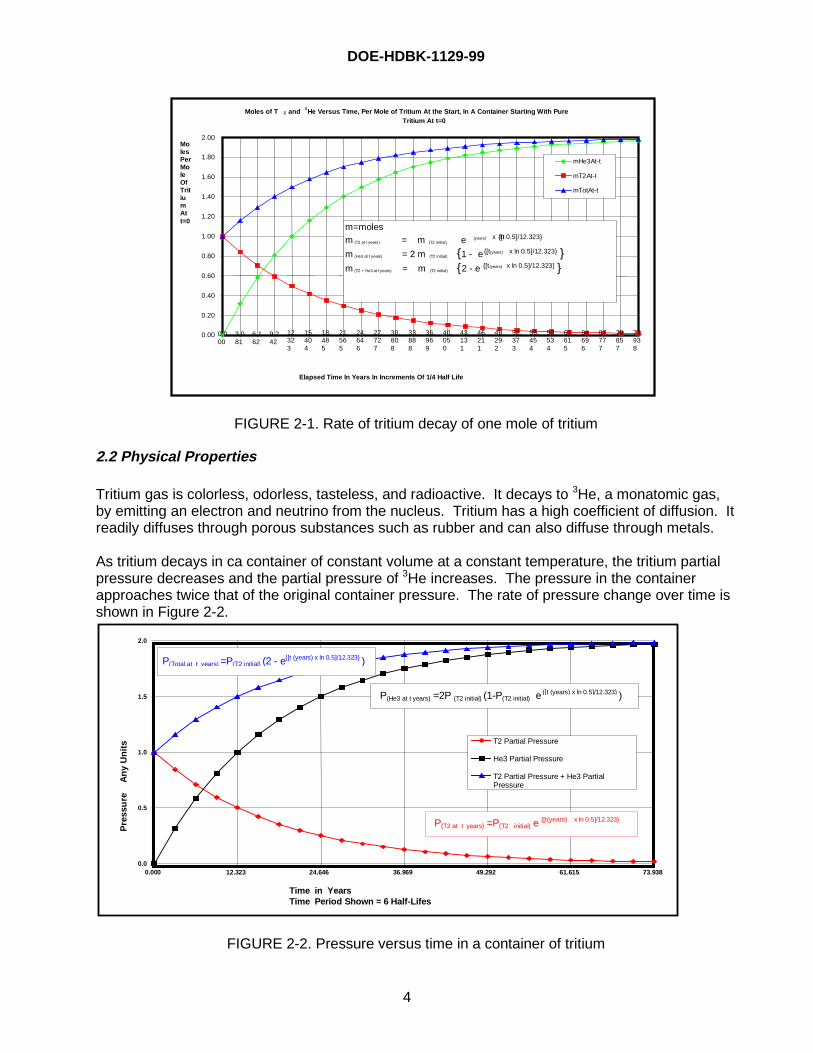
2.2 Physical Properties
Tritium gas is colorless, odorless, tasteless, and radioactive. It decays to 3He, a monatomic gas,by emitting an electron and neutrino from the nucleus. Tritium has a high coefficient of diffusion. Itreadily diffuses through porous substances such as rubber and can also diffuse through metals.
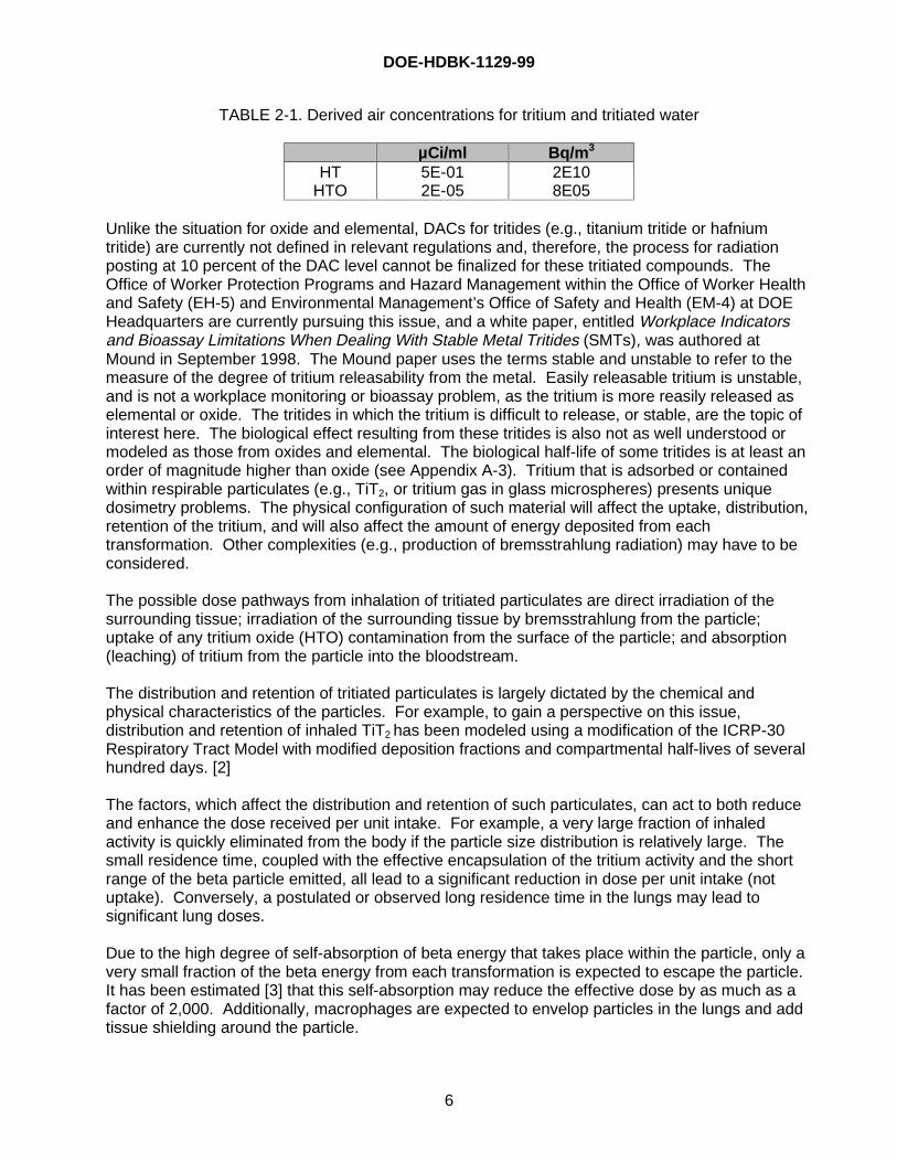
As tritium decays in ca container of constant volume at a constant temperature, the tritium partialpressure decreases and the partial pressure of 3He increases. The pressure in the containerapproaches twice that of the original container pressure. The rate of pressure change over time isshown in Figure 2-2.
0.0
0.5
1.0
1.5
2.0
0.000 12.323 24.646 36.969 49.292 61.615 73.938
Time in YearsTime Period Shown = 6 Half-Lifes
Pre
ssu
re
An
y U
nit
s T2 Partial Pressure
He3 Partial Pressure
T2 Partial Pressure + He3 PartialPressure
P(T2 at t years) =P(T2 initial) e {[t(years) x ln 0.5]/12.323}
P(He3 at t years) =2P (T2 initial) (1-P(T2 initial) e {[t (years) x ln 0.5]/12.323} )
P(Total at t years) =P(T2 initial) (2 - e{[t (years) x ln 0.5]/12.323} )
FIGURE 2-2. Pressure versus time in a container of tritium
Moles of T 2 and 3He Versus Time, Per Mole of Tritium At the Start, In A Container Starting With PureTritium At t=0
0.00
0.20
0.40
0.60
0.80
1.00
1.20
1.40
1.60
1.80
2.00
0.000
3.081
6.162
9.242
12.323
15.404
18.485
21.565
24.646
27.727
30.808
33.888
36.969
40.050
43.131
46.211
49.292
52.373
55.454
58.534
61.615
64.696
67.777
70.857
73.938
Elapsed Time In Years In Increments Of 1/4 Half Life
MolesPerMoleOfTritiumAtt=0
mHe3At-t
mT2At-t
mTotAt-t
m=molesm (T2 at t years) = m (T2 initial) e {[t(years) x ln 0.5]/12.323}
m (He3 at t years) = 2 m (T2 initial) {1 - e{[t(years) x ln 0.5]/12.323} }m (T2 + He3 at t years) = m (T2 initial) {2 - e {[t(years) x ln 0.5]/12.323} }
DOE-HDBK-1129-99
5
Other properties of tritium are listed below. Additional characteristics are given in Appendix A.
• Atomic Weight = 3.01605• Gram Molecular Weight = 6.03210• Diameter of a tritium atom (approximate) = 1.1 Angstroms• Dissociation energy, T2 to 2T = 4.59 eV• Ionization energy, T to T+ e- = 13.55 eV• Half Life = 12.323 +/- 0.004 years
In this handbook, tritium in the form of the oxide (HTO, DTO, and T2O), unless otherwise specified,is HTO. Likewise, tritium in its elemental form (HT, DT, and T2) is HT.
2.3 Chemical Properties
The electronic configuration of tritium is the same as protium and deuterium. The chemicalproperties of the isotopes are also the same. The rates of reaction vary for the different isotopesdue to the difference in the atomic masses. Additionally, the energy provided by the radioactivedecay of tritium provides the activation energy required so that some reactions will occur withtritium that will not occur with deuterium or hydrogen.
Hydrogen is present in almost all materials. If tritium is present in a material containing hydrogen,the tritium atoms will exchange with hydrogen atoms to form a tritiated molecule of the material.
2.4 Biological Properties
The body has no need for elemental hydrogen, deuterium, or tritium and does not readily absorbH2, HT, HD, D2, DT, or T2 from inhaled gases or through the skin. A small fraction of the inhaledhydrogen isotopes, in gaseous form, is not exhaled, but is dissolved in the blood stream and thenexhaled after a few minutes.
Tritium in the form of water (HTO, DTO, and T2O) is adsorbed through the skin and in the lungsfrom inhaled gases. Tritium in water form is readily retained in the body and remains with abiological half-life of approximately 10 days. Due to the body’s ready adsorption of tritium in theform of tritiated water, exposure to tritiated water in air is up to 25,000 times more hazardous thanexposure to gaseous tritium (HT, DT, and T2).
The Derived Air Concentration (DAC) for tritium is the airborne concentration that, if inhaled over aone-year period, would produce approximately a 5-rem dose to the “average” worker. The DAC isderived by the formula:
DAC = ALI/2400
where DAC = derived air concentration (µCi/m3)ALI = annual limit of intake (µCi)2400 = breathing volume for the average worker over 1 year in m3
= .02 m3/min x 60 min/hr x 40 hr/wk x 50 wk/yr
The DACs for elemental tritium and tritiated water [1] are listed in Table 2-1.
DOE-HDBK-1129-99
6
TABLE 2-1. Derived air concentrations for tritium and tritiated water
µCi/ml Bq/m 3
HTHTO
5E-012E-05
2E108E05
Unlike the situation for oxide and elemental, DACs for tritides (e.g., titanium tritide or hafniumtritide) are currently not defined in relevant regulations and, therefore, the process for radiationposting at 10 percent of the DAC level cannot be finalized for these tritiated compounds. TheOffice of Worker Protection Programs and Hazard Management within the Office of Worker Healthand Safety (EH-5) and Environmental Management’s Office of Safety and Health (EM-4) at DOEHeadquarters are currently pursuing this issue, and a white paper, entitled Workplace Indicatorsand Bioassay Limitations When Dealing With Stable Metal Tritides (SMTs), was authored atMound in September 1998. The Mound paper uses the terms stable and unstable to refer to themeasure of the degree of tritium releasability from the metal. Easily releasable tritium is unstable,and is not a workplace monitoring or bioassay problem, as the tritium is more reasily released aselemental or oxide. The tritides in which the tritium is difficult to release, or stable, are the topic ofinterest here. The biological effect resulting from these tritides is also not as well understood ormodeled as those from oxides and elemental. The biological half-life of some tritides is at least anorder of magnitude higher than oxide (see Appendix A-3). Tritium that is adsorbed or containedwithin respirable particulates (e.g., TiT2, or tritium gas in glass microspheres) presents uniquedosimetry problems. The physical configuration of such material will affect the uptake, distribution,retention of the tritium, and will also affect the amount of energy deposited from eachtransformation. Other complexities (e.g., production of bremsstrahlung radiation) may have to beconsidered.
The possible dose pathways from inhalation of tritiated particulates are direct irradiation of thesurrounding tissue; irradiation of the surrounding tissue by bremsstrahlung from the particle;uptake of any tritium oxide (HTO) contamination from the surface of the particle; and absorption(leaching) of tritium from the particle into the bloodstream.
The distribution and retention of tritiated particulates is largely dictated by the chemical andphysical characteristics of the particles. For example, to gain a perspective on this issue,distribution and retention of inhaled TiT2 has been modeled using a modification of the ICRP-30Respiratory Tract Model with modified deposition fractions and compartmental half-lives of severalhundred days. [2]
The factors, which affect the distribution and retention of such particulates, can act to both reduceand enhance the dose received per unit intake. For example, a very large fraction of inhaledactivity is quickly eliminated from the body if the particle size distribution is relatively large. Thesmall residence time, coupled with the effective encapsulation of the tritium activity and the shortrange of the beta particle emitted, all lead to a significant reduction in dose per unit intake (notuptake). Conversely, a postulated or observed long residence time in the lungs may lead tosignificant lung doses.
Due to the high degree of self-absorption of beta energy that takes place within the particle, only avery small fraction of the beta energy from each transformation is expected to escape the particle.It has been estimated [3] that this self-absorption may reduce the effective dose by as much as afactor of 2,000. Additionally, macrophages are expected to envelop particles in the lungs and addtissue shielding around the particle.
DOE-HDBK-1129-99
7
The contribution to dose from bremsstrahlung has been estimated. [2-3] Although this contributionis probably relatively small, it should be considered in the evaluation of lung doses from significantintakes of tritiated particulates.
Recently, estimates of effective doses from inhalation of various types of tritiated particulates weremade [4]. These estimates are based on in-vitro and animal (rat) studies with titanium tritide. Theassumption is made that the tritium, once dissolved, has the same distribution and retention asHTO in the body. The dose conversion factors (DCF) calculated for such intakes in adults arelisted in Table 2-2.
TABLE 2-2. ICRP-71 dose conversion factors forinhalation of tritiated particulates
Lung Absorption Type* DCF (Sv/Bq inhaled) DCF (rem/µCi inhaled)Fast
ModerateSlow
6.2 E-124.5 E-112.6 E-10
2.3 E-051.7 E-049.6 E-04
*Based on ICRP-66 Respiratory Tract Model and ICRP 60 Tissue Weighting Factors
The dose from inhalation of tritiated particulates must be evaluated on a case-by-case basis. Ingeneral, as with any suspected intake of tritium, urine samples should be collected. In the event ofa suspected significant exposure of tritiated particulates, collection of early (first few days) fecalsamples should be considered. Inhaled particulates are expected to be eliminated via this route.Cases involving inhalation of metal tritides have occurred in which significant tritium was seen inthe feces, but not in the urine [5]. Collection and analysis of fecal samples (analysis based onfecal sampling must be cognizant of particle matrix absorption effects) allows confirmation of intakeand may give information regarding the fractional uptake.
2.5 Preferred Forms
Most tritium in the DOE complex exists as a gas, in the form of tritiated water, or as a metal tritide.The preferred form of tritium is dependent upon its use in a process, length of storage, or itsclassification as a waste.
2.5.1 Characterization of Tritium Forms
2.5.1.a Gaseous Tritium
The use, transfer, storage, and shipment of gaseous tritium at or near atmospheric pressure has along history in the DOE complex and has been safely used for over thirty years. Gaseous tritium ator near atmospheric pressure occupies 22.414 L/mole at 0° C, and approximately 24.2 L/mole atroom temperature, and requires approved packages for shipment in either Type A or B quantities.If the containers are not properly designed or if they are damaged, the gas can leak from thecontainer into the environment.
Gaseous tritium at ambient pressure is easily handled by most gas handling systems and is a goodsource for general-purpose use. At low pressure and temperature, the tritium does not penetratedeeply into the container wall. Helium and tritium embrittlement of the container wall is not asignificant issue at low pressures even after several years of exposure. As tritium decays, thepressure in the container increases (see Figure 2-2) due to the generation of the monatomic gas
DOE-HDBK-1129-99
8
3He. This pressure increase, at most, would only be double the initial pressure. This factor shouldbe considered during the initial design of the vessel so it does not become an issue.
Gaseous tritium at high pressure takes up less space but is more difficult to contain in part due tothe potential for tritium and helium embrittlement of the vessel materials. This embrittlementincreases the probability of a tritium leak or catastrophic container failure. Unloading high-pressure gas requires specifically designed systems and experienced, skilled operators.
2.5.1.b Metal Tritides
Metal tritides reduce the overall volume of the stored tritium, but some of the finely divided metalsused are pyrophoric. Some metals form low melting point alloys with the materials used in theconstruction of the metal tritide containers. Others require extremely high temperatures in order torecover tritium from the material.
2.5.1.c Tritiated Water
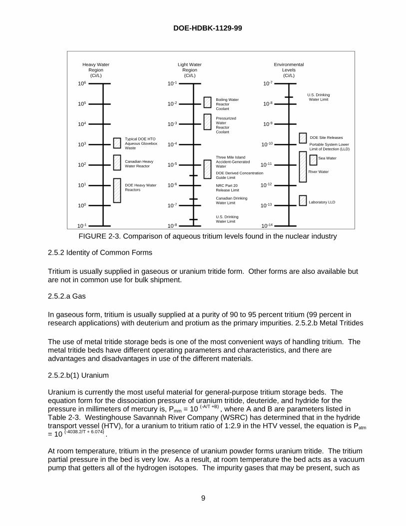
Tritium in the form of T2O may be difficult to store for long periods due to its corrosive properties.Classified experiments with T2O indicate that pure T2O is corrosive. This corrosiveness is likelydue to tritium oxide generating free radicals (OH-) from radiolytic decomposition of water in additionto extra energy from beta decay impinging on surrounding molecules. Additionally, pure T2O, likedistilled H2O, will dissolve many materials. No data currently exist that quantify the degree ofcorrosiveness; therefore, there is no basis to definitively state that the U. S. EnvironmentalProtection Agency (EPA) threshold of corrosivity (i.e., a characteristic of hazardous waste), definedin Code of Federal Regulations 40 CFR 261.22, is not exceeded. The authors believe, however,that only a high-purity product, and not waste, would have a reasonable chance of exceeding thisthreshold. A broader discussion of the relationship between tritiated water and hazardous wastesis contained in Section 3.1.3.
Dilute tritiated water recovered from tritium removal systems has also proven to be corrosive anddifficult to contain. In a severe case, storage of tritiated water recovered from tritium removalsystems in liquid form at concentrations as low as a few curies per milliliter has corroded throughthe weld area of stainless steel vessels after only a few days of exposure. In this specific example,it is probable that the extreme corrosive nature of this dilute tritiated water was due, in largemeasure, to chlorine contamination of the catalyst in the tritium removal system. This corrosion isevidently inhibited by absorption of the tritiated water on clay or in molecular sieve material.
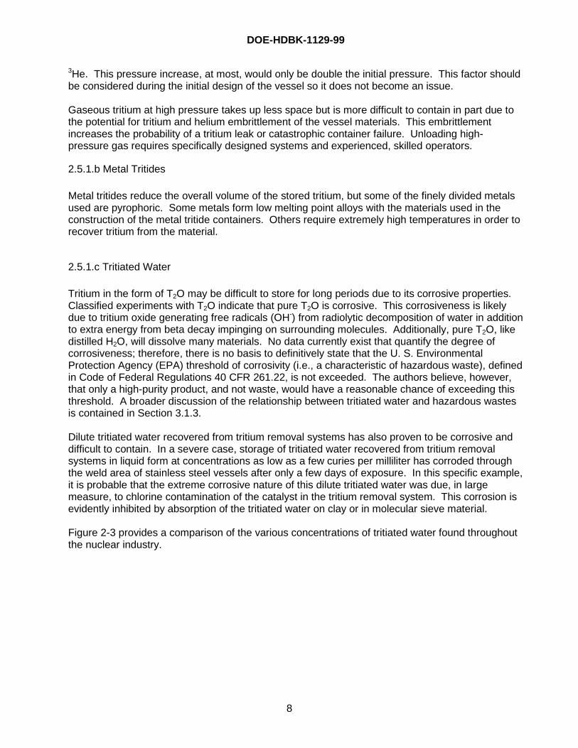
Figure 2-3 provides a comparison of the various concentrations of tritiated water found throughoutthe nuclear industry.
DOE-HDBK-1129-99
9
106
105
104
103
102
101
100
10-1
Heavy WaterRegion(Ci/L)
Typical DOE HTOAqueous GloveboxWaste
Canadian HeavyWater Reactor
DOE Heavy WaterReactors
Light WaterRegion(Ci/L)
10-1
10-2
10-3
10-5
10-6
10-7
10-8
10-4
Boiling WaterReactorCoolant
PressurizedWaterReactorCoolant
Three Mile IslandAccident-GeneratedWater
NRC Part 20Release Limit
Canadian DrinkingWater Limit
U.S. DrinkingWater Limit
EnvironmentalLevels(Ci/L)
10-7
10-8
10-9
10-10
10-11
10-12
10-13
10-14
Sea Water
River Water
Laboratory LLD
Portable System LowerLimit of Detection (LLD)
DOE Site Releases
U.S. DrinkingWater Limit
DOE Derived ConcentrationGuide Limit
FIGURE 2-3. Comparison of aqueous tritium levels found in the nuclear industry
2.5.2 Identity of Common Forms
Tritium is usually supplied in gaseous or uranium tritide form. Other forms are also available butare not in common use for bulk shipment.
2.5.2.a Gas
In gaseous form, tritium is usually supplied at a purity of 90 to 95 percent tritium (99 percent inresearch applications) with deuterium and protium as the primary impurities. 2.5.2.b Metal Tritides
The use of metal tritide storage beds is one of the most convenient ways of handling tritium. Themetal tritide beds have different operating parameters and characteristics, and there areadvantages and disadvantages in use of the different materials.
2.5.2.b(1) Uranium
Uranium is currently the most useful material for general-purpose tritium storage beds. Theequation form for the dissociation pressure of uranium tritide, deuteride, and hydride for thepressure in millimeters of mercury is, Pmm = 10 (-A/T +B) , where A and B are parameters listed inTable 2-3. Westinghouse Savannah River Company (WSRC) has determined that in the hydridetransport vessel (HTV), for a uranium to tritium ratio of 1:2.9 in the HTV vessel, the equation is Patm
= 10 (-4038.2/T + 6.074) .
At room temperature, tritium in the presence of uranium powder forms uranium tritide. The tritiumpartial pressure in the bed is very low. As a result, at room temperature the bed acts as a vacuumpump that getters all of the hydrogen isotopes. The impurity gases that may be present, such as
DOE-HDBK-1129-99
10
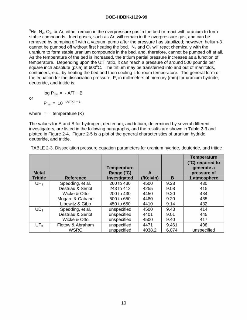
3He, N2, O2, or Ar, either remain in the overpressure gas in the bed or react with uranium to formstable compounds. Inert gases, such as Ar, will remain in the overpressure gas, and can beremoved by pumping off with a vacuum pump after the pressure has stabilized; however, helium-3cannot be pumped off without first heating the bed. N2 and O2 will react chemically with theuranium to form stable uranium compounds in the bed, and, therefore, cannot be pumped off at all.As the temperature of the bed is increased, the tritium partial pressure increases as a function oftemperature. Depending upon the U:T ratio, it can reach a pressure of around 500 pounds persquare inch absolute (psia) at 600oC. The tritium may be transferred into and out of manifolds,containers, etc., by heating the bed and then cooling it to room temperature. The general form ofthe equation for the dissociation pressure, P, in millimeters of mercury (mm) for uranium hydride,deuteride, and tritide is:
log Pmm = - A/T + Bor
Pmm = 10 –(A/T(K)) + B
where T = temperature (K)
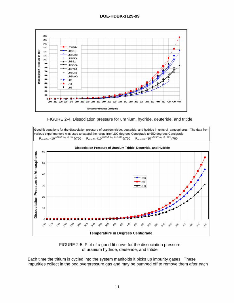
The values for A and B for hydrogen, deuterium, and tritium, determined by several differentinvestigators, are listed in the following paragraphs, and the results are shown in Table 2-3 andplotted in Figure 2-4. Figure 2-5 is a plot of the general characteristics of uranium hydride,deuteride, and tritide.
TABLE 2-3. Dissociation pressure equation parameters for uranium hydride, deuteride, and tritide
MetalTritide Reference
TemperatureRange (oC)
InvestigatedA
(/Kelvin) B
Temperature(°C) required to
generate apressure of
1 atmosphereUH3 Spedding, et al.
Destriau & SeriotWicke & Otto
Mogard & CabaneLibowitz & Gibb
260 to 430243 to 412200 to 430500 to 650450 to 650
45004255445044804410
9.289.089.209.209.14
430415434435432
UD3 Spedding, et al.Destriau & Seriot
Wicke & Otto
unspecifiedunspecifiedunspecified
450044014500
9.439.019.40
414445417
UT3 Flotow & AbrahamWSRC
unspecifiedunspecified
44714038.2
9.4616.074
408unspecified
DOE-HDBK-1129-99
11
FIGURE 2-4. Dissociation pressure for uranium, hydride, deuteride, and tritide
FIGURE 2-5. Plot of a good fit curve for the dissociation pressureof uranium hydride, deuteride, and tritide
Each time the tritium is cycled into the system manifolds it picks up impurity gases. Theseimpurities collect in the bed overpressure gas and may be pumped off to remove them after each
0
100
200
300
400
500
600
700
800
900
1000
1100
1200
1300
1400
1500
1600
200 210 220 230 240 250 260 270 280 290 300 310 320 330 340 350 360 370 380 390 400 410 420 430 440
Temperature Degrees Centigrade
Dis
soci
atio
n P
ress
ure
in t
orr
UT3-FlAb
UD3-Spd
UD3-DeSe
UD3-WiOtUH3-Spd
UH3-DeSe
UH3-WiOt
UH3-LiGi)
UH3-MoCa
UD3
UT3
UH3
Dissociation Pressure of Uranium Tritide, Deuteride, and Hydride
0
10
20
30
40
50
60
200
220
240
260
280
300
320
340
360
380
400
420
440
460
480
500
520
540
560
580
600
620
640
660
Temperature in Degrees Centigrade
Dis
soci
atio
n P
ress
ure
in A
tmo
sph
eres
UD3
UT3
UH3
Good fit equations for the dissociation pressure of uranium tritide, deuteride, and hydride in units of atmospheres. The data from various experimenters was used to extend the range from 200 degrees Centigrade to 650 degrees Centigrade.
PatmUD3={10-(4500/T deg K) +9.4 }/760 PatmUT3={10-(4471/T deg K) +9.461 }/760 PatmUH3={10-(4525/T deg K) +9.27}/760
DOE-HDBK-1129-99
12
heating/cooling cycle. Active impurity gases, such as oxygen and nitrogen, are irreversiblyremoved by reaction with the uranium.
Disadvantages to using uranium tritide beds are: 1) uranium powder is pyrophoric; 2) thegeneration of significant tritium pressure requires a high temperature that results in permeation oftritium through the vessel wall; and 3) the capacity is also permanently reduced by exposure toactive impurity gases.
2.5.2.b(2) Palladium
Palladium is a metallic element of group 8 in the Periodic Table. The symbol for palladium is Pd,the atomic number is 46, the atomic weight is 106.42, and the melting point is 1554.9°C.
At room temperature, palladium absorbs up to 900 times its own volume in hydrogen. It diffuseseasily through heated palladium; this is one means of purifying the gas. Finely divided Pd is agood catalyst, and is used for hydrogenation and dehydrogenation reactions. Palladium metal isused in dentistry, as an alloy in making jewelry, and in making surgical instruments, watches, andelectrical contacts.Palladium powder is currently the second most used material for general-purpose tritium storagebeds. Palladium can be obtained in powdered form and loaded directly into the container used forthe metal tritide bed. Palladium was used extensively at both LLNL and SNLL in the tritiumstorage beds.
When the tritium is exposed to the powder, it dissolves in the palladium powder with a maximumPd:T ratio of approximately 0.7. Palladium powder is not pyrophoric, but it has a higher tritiumpartial pressure than uranium at room temperature.
At room temperature, tritium, deuterium, and protium dissolve in the palladium powder and thetritium partial pressure in the gas over the powder is approximately 50 torr. The over pressureincreases as a function of temperature. As the temperature of the palladium is increased byheating the bed, the tritium partial pressure increases as a function of the temperature and reachesa pressure of around 750 psia at 350oC. The general form of the equation for the dissociationpressure, P, in millimeters of mercury (mm) for palladium hydride, deuteride, and tritide is:
log Pmm = (-A/T + B)or
Pmm = 10 (-A/T + B)
Where T= temperature (K)
The values for A and B for hydrogen and deuterium determined by different investigators are givenin Table 2-4, and the equations developed by the different experimenters over the temperaturerange they investigated are plotted in Figure 2-6.
DOE-HDBK-1129-99
13
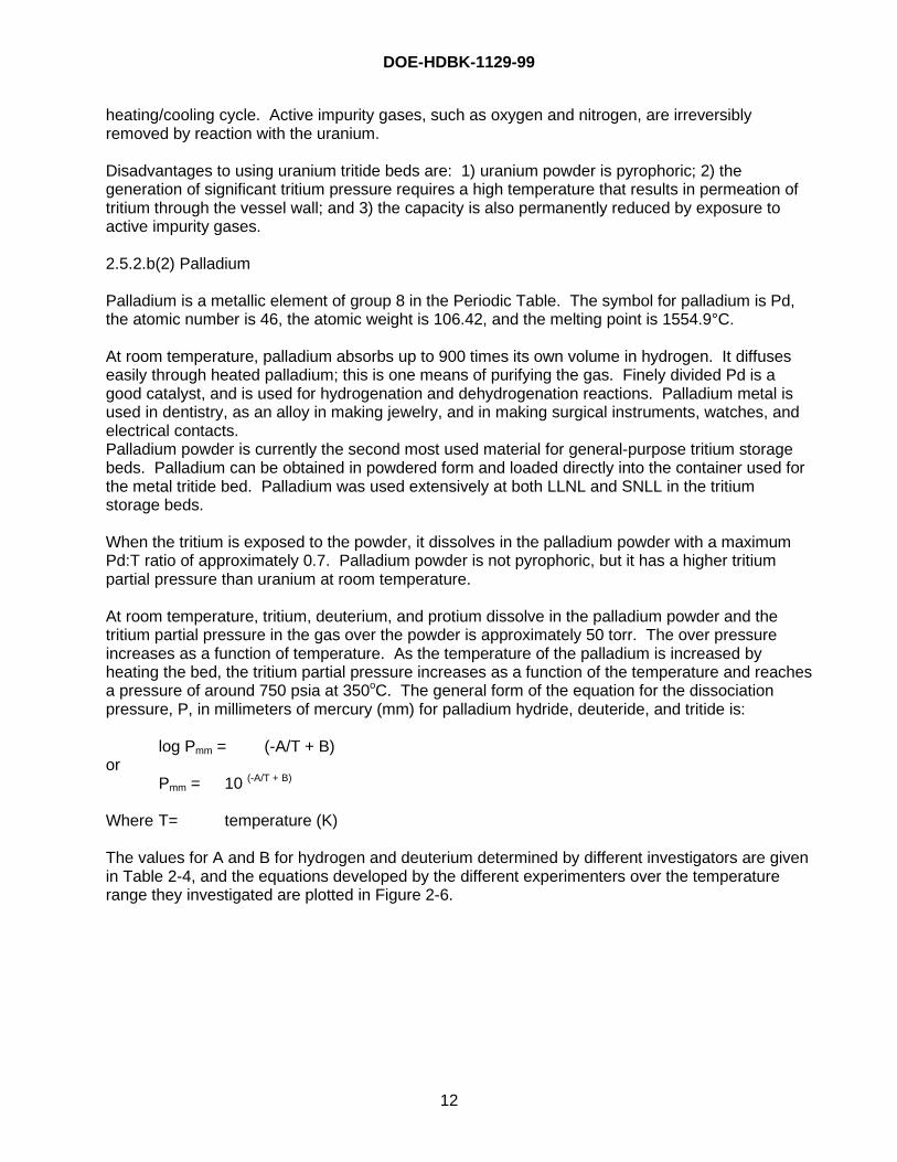
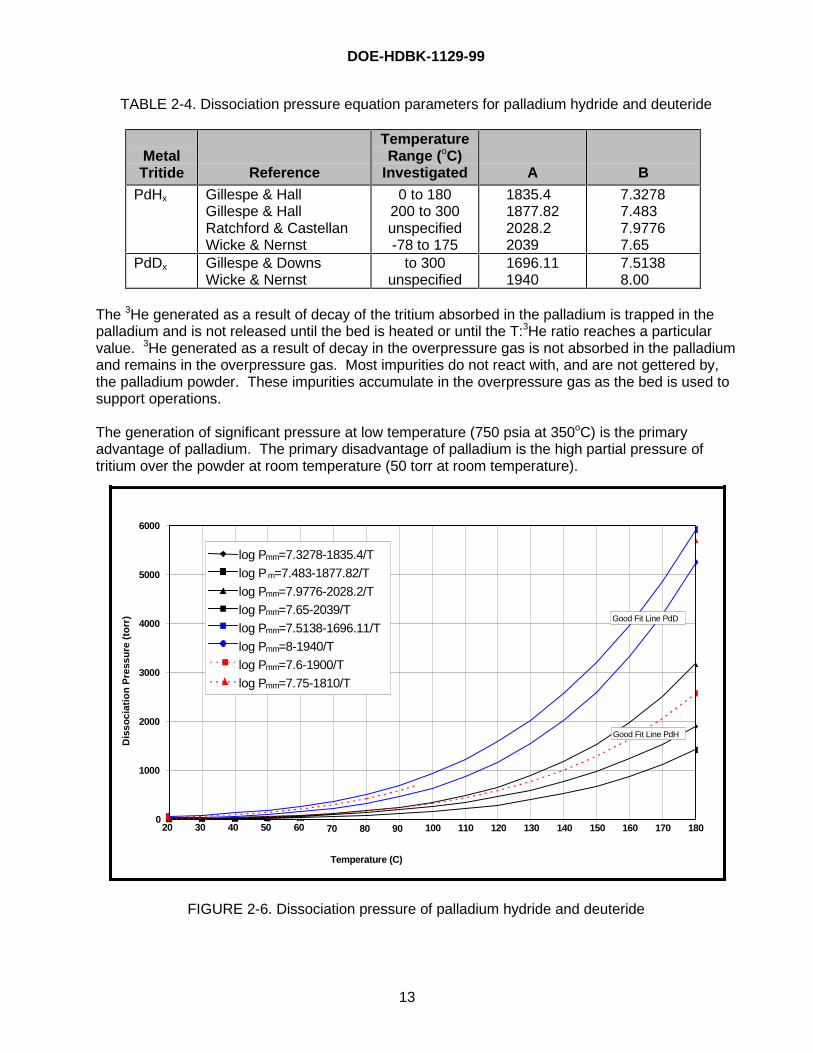
TABLE 2-4. Dissociation pressure equation parameters for palladium hydride and deuteride
MetalTritide Reference
TemperatureRange (oC)
Investigated A B
PdHx Gillespe & HallGillespe & HallRatchford & CastellanWicke & Nernst
0 to 180200 to 300unspecified-78 to 175
1835.41877.822028.22039
7.32787.4837.97767.65
PdDx Gillespe & DownsWicke & Nernst
to 300unspecified
1696.111940
7.51388.00
The 3He generated as a result of decay of the tritium absorbed in the palladium is trapped in thepalladium and is not released until the bed is heated or until the T:3He ratio reaches a particularvalue. 3He generated as a result of decay in the overpressure gas is not absorbed in the palladiumand remains in the overpressure gas. Most impurities do not react with, and are not gettered by,the palladium powder. These impurities accumulate in the overpressure gas as the bed is used tosupport operations.
The generation of significant pressure at low temperature (750 psia at 350oC) is the primaryadvantage of palladium. The primary disadvantage of palladium is the high partial pressure oftritium over the powder at room temperature (50 torr at room temperature).
FIGURE 2-6. Dissociation pressure of palladium hydride and deuteride
0
1000
2000
3000
4000
5000
6000
20 30 40 50 60 70 80 90 100 110 120 130 140 150 160 170 180
Temperature (C)
Dis
soci
atio
n P
ress
ure
(to
rr)
log Pmm=7.3278-1835.4/T
log P m=7.483-1877.82/T
log Pmm=7.9776-2028.2/Tlog Pmm=7.65-2039/T
log Pmm=7.5138-1696.11/T
log Pmm=8-1940/T
log Pmm=7.6-1900/T
log Pmm=7.75-1810/T
Good Fit Line PdD
Good Fit Line PdH
DOE-HDBK-1129-99
14
2.5.2.b(3) Titanium
Titanium is a metallic element in group 4 of the Periodic Table. The symbol is Ti, the atomicnumber is 22, the atomic weight is 47.90, and the melting point is 1660oC. It is a low-cost metal,and can absorb and store tritium in a compact solid form at a tritium pressure of approximately 1E-7 torr.
Titanium hydride, TiH2, in powder form, is a black metallic dust that is less prone to spontaneousignition in air than the parent metal. Finely divided titanium hydride is reported to ignite at 440oCand its dust is an explosion hazard, which dissociates above 288oC. Titanium hydride is used inpowder metallurgy, hydrogen production, foamed metals, glass solder, and refractories, and as agas getter in the electronics industry. Titanium tritide in solid or massive form is stable in air forextended periods of time. Titanium retains the decay helium up to a concentration of 0.3 He atomper Ti atom. Both SRS [6] and Ontario Hydro [7-11] have selected titanium as their long-termstorage medium. The SRS titanium beds have an expected useful life of less than 10 years, whilethe Ontario Hydro beds are expected to be in operation for well over 20 years. The Canadians arenot space-restricted, and therefore do not load their beds to the degree that SRS does.Additionally, longer times to maximum helium retention ratio (0.3 He/Ti) can be achieved bydiluting the tritium concentration with deuterium or protium.
2.5.2.b(4) Zirconium
Zirconium is a metallic element of group 4 in the Periodic Table. The symbol for zirconium is Zr,the atomic number is 40, and the atomic weight is 91.22. Zirconium is flammable as a powder andmelts at 1850oC. Zirconium is a hard, lustrous, grayish metal that is strong and ductile, and is usedin alloys, pyrotechnics, welding fluxes, and explosives.
Zirconium hydride ZrH2 is a flammable gray-black powder and is used in powder metallurgy,nuclear moderators, and as a reducing agent. Finely divided zirconium hydride suspended in airwill ignite at 430oC. Zirconium hydride contains about twice as many hydrogen atoms per unit ofvolume as liquid hydrogen. Massive zirconium hydride is stable in air for extended periods of timeat temperatures below 600oC.
Certain DOE radioactive zirconium fines (which are destined for disposal) are managed as D001mixed ignitable wastes. These radioactive zirconium fines are pyrophoric under 40 CFR261.21(a)(2) – i.e., they are capable of causing fire through friction. If zirconium used for tritiumstorage beds is destined for disposal (i.e., constitutes a waste), the RCRA hazardous wastecharacteristic of ignitability must be analyzed. A broader discussion of RCRA hazardous waste iscontained in Section 3.1.3.
2.5.2.b(5) Societá Apparecchi Elettrici e Scientifici (SAES) Getters
During the past several years, investigations have been conducted concerning the use of SAESGetters to remove tritium from tritium-contaminated gaseous waste streams. These investigationshave concentrated on getters that cracked the gases containing tritium and removed the resultingfree tritium from the gas stream. The primary advantage of these getter systems is that tritium isnot converted by the tritium removal system to the more radiotoxic tritiated water. Additionally, thetritium can be recovered in gaseous form from the getter, purified, and reused.
The materials being tested include those manufactured in the form of pressed pellets that can beused in low pressure drop packed bed reactors designed for the size required by the application
DOE-HDBK-1129-99
15
flow rate and lifetime requirements. The basic strategy currently being implemented in prototypesystems is to crack the molecules on a hot getter and remove the non-tritiated reactive impuritiesthat interfere with the performance of the hydrogen gettering alloys. Following purification, the gasis passed through a hydrogen gettering bed to remove the hydrogen isotopes from the gas stream.
2.5.2.b(6) LaNi5 Based Alloys
The use of lanthanum-nickel hydrides has been a continuing topic of interest, and as recently as1997, promising results for hydrogen storage have been reported (“LaNi5 Intermetallic Hydride,”extracted from State-of-the-Art Review of Hydrogen Storage in Reversible Metal Hydrides forMilitary Fuel Cell Applications, Gary Sandrock, Ph.D., for the Department of the Navy, Office ofNaval Research, N00014-97-M-0001, July 24, 1997). Promising research results were alsoreported in the literature in 1988 (“Hydrogen Isotope Sorption Properties of LaNi3Mn2 Alloy as aCandidate for the Tritium Storage Material,” T. Ide et al., Sumitomo Heavy Industries, Ltd. and H.Yoshida et al., Japan Atomic Research Institute, published in Fusion Technology, September1988). Earlier research at Mound, however, in the 1970s and early 1980s indicated thatlanthanum-nickel-based alloys were not appropriate for tritium service due, in part, todisproportionation. When cycled, the LaNi5 had a tendency to separate to form the parent metals(La or Ni) or different alloys. The disproportionation tended to change the pressure, concentration,and temperature properties of the metal/alloy mix and increase the quantity of tritium bound in theheel that was not easily recoverable.
Further investigations will be needed to better ascertain the capabilities of LaNi alloys for tritiumservice.
2.5.2.c Absorbed Water
Molecular sieve material is used in tritium removal systems for removal of water contaminated withtritium. Systems such as tritium removal systems, effluent recovery systems, and cleanup systemsremove tritium from a gas by cracking the tritium-containing components on a heated preciousmetal catalyst. The free tritium then combines with oxygen in the gas stream to form tritiatedwater. The gas stream is then cooled to room temperature, and the water contained in the gasstream, including the tritiated water, is removed by a molecular sieve trap.
A molecular sieve will hold about 18 percent water by weight, and the sieve may be regenerated toremove the water so it can be reused. The issue of flammability limits of these containers isdiscussed in Section 3.1.2. Tritiated water absorbed on molecular sieve is not corrosive and maybe stored in this way for long periods without damage to the container wall.
Water contaminated with HTO is also stored on clay. The common method of solidification oftritium-contaminated wastewater for disposal is to solidify the water on clay so that it can beclassified as solid waste. Clay will hold approximately 60 percent water by volume. Wastedisposal sites generally require the use of 100 percent more clay than required to solidify thewater, and, as a result, the water is generally limited to 30 percent of the volume of the clay forwaste solidification purposes. Water absorbed on clay is not corrosive and may be stored for longperiods without damage to the container wall.
DOE-HDBK-1129-99
16
2.5.3 Summary
2.5.3.a Best for Storage Conditions
The decision on storage media is a function of the storage length and frequency of unloadings.Media range from gas (short time frame, many movements) to titanium (long time frame, few or nomovements) with other media (e.g., uranium) in between. Although the preferred form for storageis a metal tritide and the least desirable form is a liquid, there are always exceptions to this rule.Factors to be considered include:
Solid (Metal Tritides): Unless already in solid form, tritium is not readily available as a solid metaltritide and requires conversion before storage. Metal tritides can store large quantities of tritiumwithout occupying large volumes, but the storage containers are more complex than gaseousstorage containers. Depending upon the metallic tritide chosen for storage, there are bothadvantages and disadvantages. Titanium tritide is very stable, even when exposed to air, but it ismore difficult to recover tritium from the titanium than from other metals. Stored as uranium tritide,the tritium can be easily and quickly recovered and provides for the removal of most impurities thatmight accumulate during storage. However, uranium powder is also pyrophoric, and startsreleasing 3He after a few months.
Liquid (T2O): Tritium is not readily available in water form and requires conversion before storage.It is up to 25,000 times more hazardous in oxide form than in elemental form. It takes very littlespace, but is difficult to store due to the corrosivity of the water. The tritiated liquid can besolidified on clay, molecular sieves, or polymers prior to disposal. It may also be converted to itsgaseous form for storage purposes. In either case, the final decision should be based on thequantity of tritium and the tritium concentration of the water to be stored.
Gas (T2): Tritium is readily available in gaseous form. A great deal of experience already exists onthe design of gaseous tritium storage systems. As a gas it takes up more volume than as a liquidor solid, and can be easily released to the environment if the tritium container is breached. Gasalso presents a flammability vulnerability.
2.5.3.b Best for Operations/Process
Solid (Metal Tritides): When used as a gas in research where tritium is issued and returned as agas, there are advantages to the use of uranium beds for storage. The heating/cooling cycle usedto store and recover tritium from the bed results in routine removal of the 3He and other impuritiesfrom the tritium supply. It can be reused in other processes at reasonably high purity. Additionally,storage as a metal tritide allows the bed to be used as a pressure generator and, in some cases,eliminates the need for mechanical pumps.
Liquid (T2O): Unless the process itself uses tritium in the form of water, there are no advantages tostorage of tritium in liquid form for operations.
Gas (T2): Tritium is primarily used in gaseous form, purified in gaseous form, assayed in gaseousform, and is more useful in this form than any other form. As a result, storage in gaseous form foroperations is appropriate.
DOE-HDBK-1129-99
17
2.5.3.c Best for Disposal Conditions
Disposing of tritium in the form of a liquid waste or gaseous waste is difficult. Generally speaking,waste tritium is converted to solid form so that the material can be disposed of as a solid low-level(radioactive) waste, assuming there is no RCRA hazardous component.
Solid (Metal Tritide): It is possible to dispose of gaseous tritium by converting it to a solid metaltritide. However, the disposal site requires that the metal tritide not be pyrophoric. If it is inparticulate form, the metal tritide must be contained to meet disposal site requirements.
Liquid (T2O): If the waste is in gaseous form, the tritium is normally removed from the gas mixtureand is reused. If the concentration of tritium in the waste gas is too low to make recovery of thetritium economically worthwhile, the waste gas is sent to an effluent processing system where thetritium is removed before the gases are released to the environment. The current effluentprocessing systems remove tritium from the waste gas by converting it to water. The water is thensolidified on molecular sieve, clay, mixtures of clay and cement, or Stergo superabsorbent(discussed in Section 8.1.4.b(2)), and is then packaged as solid waste and shipped to the disposalsite.
Gas (T2): Waste disposal sites generally will not accept packages containing pressurized gases orthose in which a potential exists for generating 1.5 atmospheres (absolute) of pressure over time.
3.0 BASIC TRITIUM REGULATORY INFORMATION
Due to its more hazardous profile, most of the regulatory interest in tritium is concerned with theoxide form. Figure 2-3 pictorially illustrates various concentrations and regulatory set points. Theradiological materials inventory for tritium accounting purposes may not coincide with theradiological materials inventory for safety analysis report (SAR) purposes, which may not coincidewith the radiological materials inventory for Environmental Impact Statement (EIS) purposes. Thisis due to prescribed allowances for excluding various portions of the inventory, as discussed inSections 3.1 and 3.3.
3.1 Tritium Accountability
3.1.1 Radiological Materials Inventory
The Atomic Energy Act describes three categories of materials: Byproduct, Source and SpecialNuclear Material (SNM). There are also three categories of nuclear materials described in DOEOrder 5633.3B, “Control and Accountability of Nuclear Materials”: SNM, Source and Other. Theorder designates that tritium is an “Other” category material and is accountable nuclear material.
Tritium is accountable for DOE down to 0.01 grams. Items that contain tritium quantities of 0.005grams or greater are rounded to the nearest 0.01 grams and become accountable items. Itemsthat contain less than 0.005 grams round to zero and are not accountable items. For the purposesof accountability, the radiological materials inventory of tritium is the sum of the tritium quantitiescontained in the accountable items. This sum does not include any items that contain less than
DOE-HDBK-1129-99
18
0.005 grams of tritium or other items that are not part of the facility accountable nuclear materialsinventory.
Quantities of tritium contained in waste may be part of the facility accountable nuclear materialsinventory until it is removed from the facility to a waste accumulation area for storage or to a wastepackaging area for packaging. Waste can also be put in a prescribed form, as specified in DOEOrder 5633.3B. Individual waste items that contain at least 0.005 grams of tritium are accountablenuclear materials items and become part of the facility accountable nuclear materials inventory.
Tritium contained in water (H2O or D2O) used as a moderator in a nuclear reactor is not anaccountable material.
DOE requires that a tritium facility establish material control and accountability systems to provideaccurate nuclear materials inventory information. The facility tritium inventory and scrap levels oftritium must be minimized consistent with the operational needs and safeguards practices of thefacility.
For each facility, a materials control and accountability program must be established for all nuclearmaterials on inventory, including those designated as uneconomical to recover.The facility materials control and accountability system should include the following:
• Accounting System Database• Account Structure• Records and Reports• Physical Inventories• Periodic Physical Inventories• Special Inventories• Inventory Verification/Confirmation Measurements• Measurements and Measurement Control• Organization• Selection and Qualification of Measurement Methods• Training and Qualification of Measurement Personnel• Measurement Systems• Measurement Control• Material Transfers• External Transfers• Internal Transfers• Material Control Indicators• Shipper/Receiver Difference Assessment• Inventory Difference Evaluation• Evaluation of Other Inventory Adjustments• Documentation and Reporting Forms• Procedures and Requirements
3.1.2 EPA Maximum Contaminant Level for Tritium
The current National Primary Drinking Water Regulation (NPDWR) for beta- and photon-emittingradionuclides is 4 millirem (mrem)/year. The regulatory compliance level for tritium, correspondingto the 4 mrem/year level determined by EPA (40 CFR Part 141) is 20,000 pCi/L. By comparison,
DOE-HDBK-1129-99
19
the World Health Organization and Canadian levels are approximately 200,000 pCi/L (189,000pCi/L for Canada and 210,000 pCi/L for the World Health Organization. These are based on avalue of 10 percent of the public dose limits as calculated in accordance with ICRP-60recommendations. [12]
EPA calculated a maximum contaminant level (MCL) for tritium of 20,000 pCi/L in 1976 based onvalues for worker exposure contained in Handbook 69, “Maximum Permissible Concentrations ofRadionuclides in Air and Water for Occupational Exposure,” published by the National Bureau ofStandards in 1959 and amended in 1963. This calculation assumes that an extra dose resultingfrom organically bound tritium, equal to a 20 percent increase over that determined for workerexposure dose in Handbook 69, should be factored into the MCL. The resulting MCL (20,000pCi/L) is based on not exceeding 4 mrem/year on a total body basis, and assumes a daily rate ofingestion of 2L of water.
In July 1991, EPA proposed revised MCLs for radionuclides based on its dosimetric modelRADRISK, which included many of the concepts and assumptions included in the effective doseequivalent method (ICRP 30). In the proposed regulation, EPA determined that the MCL for tritiumwas 60,900 pCi/L. DOE provided comments to EPA suggesting that the appropriate value for thetritium MCL should be 80,000 pCi/L, based on dose to soft body tissues. This value is consistentwith the Derived Concentration Guide (DCG) value in DOE Order 5400.5, “Radiation Protection ofthe Public and the Environment.” Apparently, EPA used its RADRISK model to calculate the60,900 pCi/L value, which differed from the models and parameters recommended by ICRP 30.The proposed regulation has not been finalized. Projections from EPA are that a re-proposed ruleis expected no sooner than December 2000.
In early 1997, EPA prepared a Direct Final Rule that would have updated the methodology used inthe 1976 final NPDWR. This methodology would be consistent with the method contained in ICRP30 and Federal Guidance Report 11; i.e., the effective dose equivalent concept–rather than the“total body or organ dose equivalent” method used in 1976. This direct final rule would haveretained the 4 mrem/year standard, which is based on daily ingestion of 2L of water andcorresponds to a lifetime cancer risk of 10-4. In April 1997, however, EPA determined that the SafeDrinking Water Act Amendments of 1996 contained a provision that would preclude EPA frompromulgating a standard that results in increased risk, in the context of revising an existingstandard. Although the direct final rule was described as a technical modification to themethodology used to calculate a regulatory compliance level, and that the basic standard (4mrem/year) was unchanged, the concentration levels for many of the radionuclides wouldincrease, thereby increasing risk. The level for tritium is the most dramatic example, since thechange in methodology would increase the regulatory compliance level from 20,000 pCi/L to86,000 pCi/L. To date, EPA has not promulgated this direct final rule.
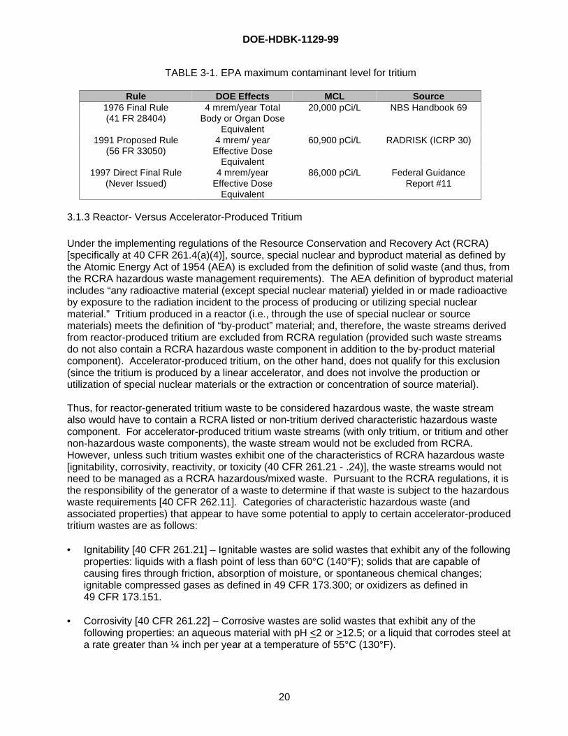
It is the current understanding of the Office of Environment Safety and Health (EH’s) that EPA isconsidering a risk-based approach to setting NPDWRs for radionuclides, rather than the dose-based approach currently followed. No decisions have been made. EH is not aware of any planfor providing an advance or draft rule for review and comment on this approach. If a risk-basedapproach were to be adopted, it is likely that the MCL for tritium would be on the order of 30,000pCi/L rather than the 60,900 pCi/L proposed in 1991. A summary of the rule and proposals isgiven in Table 3-1.
DOE-HDBK-1129-99
20
TABLE 3-1. EPA maximum contaminant level for tritium
Rule DOE Effects MCL Source1976 Final Rule(41 FR 28404)
4 mrem/year TotalBody or Organ Dose
Equivalent
20,000 pCi/L NBS Handbook 69
1991 Proposed Rule(56 FR 33050)
4 mrem/ yearEffective Dose
Equivalent
60,900 pCi/L RADRISK (ICRP 30)
1997 Direct Final Rule(Never Issued)
4 mrem/yearEffective Dose
Equivalent
86,000 pCi/L Federal GuidanceReport #11
3.1.3 Reactor- Versus Accelerator-Produced Tritium
Under the implementing regulations of the Resource Conservation and Recovery Act (RCRA)[specifically at 40 CFR 261.4(a)(4)], source, special nuclear and byproduct material as defined bythe Atomic Energy Act of 1954 (AEA) is excluded from the definition of solid waste (and thus, fromthe RCRA hazardous waste management requirements). The AEA definition of byproduct materialincludes “any radioactive material (except special nuclear material) yielded in or made radioactiveby exposure to the radiation incident to the process of producing or utilizing special nuclearmaterial.” Tritium produced in a reactor (i.e., through the use of special nuclear or sourcematerials) meets the definition of “by-product” material; and, therefore, the waste streams derivedfrom reactor-produced tritium are excluded from RCRA regulation (provided such waste streamsdo not also contain a RCRA hazardous waste component in addition to the by-product materialcomponent). Accelerator-produced tritium, on the other hand, does not qualify for this exclusion(since the tritium is produced by a linear accelerator, and does not involve the production orutilization of special nuclear materials or the extraction or concentration of source material).
Thus, for reactor-generated tritium waste to be considered hazardous waste, the waste streamalso would have to contain a RCRA listed or non-tritium derived characteristic hazardous wastecomponent. For accelerator-produced tritium waste streams (with only tritium, or tritium and othernon-hazardous waste components), the waste stream would not be excluded from RCRA.However, unless such tritium wastes exhibit one of the characteristics of RCRA hazardous waste[ignitability, corrosivity, reactivity, or toxicity (40 CFR 261.21 - .24)], the waste streams would notneed to be managed as a RCRA hazardous/mixed waste. Pursuant to the RCRA regulations, it isthe responsibility of the generator of a waste to determine if that waste is subject to the hazardouswaste requirements [40 CFR 262.11]. Categories of characteristic hazardous waste (andassociated properties) that appear to have some potential to apply to certain accelerator-producedtritium wastes are as follows:
• Ignitability [40 CFR 261.21] – Ignitable wastes are solid wastes that exhibit any of the followingproperties: liquids with a flash point of less than 60°C (140°F); solids that are capable ofcausing fires through friction, absorption of moisture, or spontaneous chemical changes;ignitable compressed gases as defined in 49 CFR 173.300; or oxidizers as defined in49 CFR 173.151.
• Corrosivity [40 CFR 261.22] – Corrosive wastes are solid wastes that exhibit any of thefollowing properties: an aqueous material with pH <2 or >12.5; or a liquid that corrodes steel ata rate greater than ¼ inch per year at a temperature of 55°C (130°F).
DOE-HDBK-1129-99
21
• Reactivity [40 CFR 261.23] – Reactive wastes are solid wastes that exhibit any of the followingproperties: (1) they are normally unstable and readily undergo violent change withoutdetonating; (2) they react violently with water; (3) they form potentially explosive mixtures withwater; (4) when mixed with water, they generate toxic gases, vapors, or fumes in a quantitysufficient to present a danger to human health or the environment; (5) they are a cyanide orsulfide bearing waste which, when exposed to pH conditions between 2 and 12.5, can generatetoxic gases, vapors, or fumes in a quantity sufficient to present a danger to human health or theenvironment; (6) they are capable of detonation or explosive reaction if subjected to a stronginitiating source or if heated under confinement; (7) they are readily capable of detonation orexplosive decomposition or reaction at standard temperature and pressure; (8) they are aforbidden explosive as defined in 49 CFR 173.51, or a Class A explosive as defined in 49 CFR173.53 or a Class B explosive as defined in 49 CFR 173.88.
The discussion in Section 2.5.1.c provides a qualitative argument for the determination that forwaste, the characteristic of corrosivity typically are not exhibited. However, little data are currentlyavailable to confirm whether or not the vapor space of some tritium containers (e.g. tritium oxideadsorbed on molecular sieves) would exhibit the hazardous characteristic of ignitability or reactivityover time due to radiolytic decay. As explained above, reactor-generated tritium waste streamsthat do not contain a hazardous waste component may be excluded from the RCRA hazardouswaste regulations pursuant to 40 CFR 261.4(a)(4). This may be the case even if sufficientquantities of both hydrogen and oxygen are present to exhibit characteristics of ignitability orreactivity. This is based on a regulatory policy that EPA has applied in certain cases wherebyresiduals derived from the management of exempt or excluded waste retain the exemption orexclusion. [13-17] However (as indicated above), if a tritium waste (reactor- or accelerator-produced) also contains a distinct hazardous waste component, the waste stream should bemanaged as a radioactive mixed waste under the AEA and RCRA.
The application of RCRA to certain tritium waste streams may be subject to regulatoryinterpretation and enforcement discretion. With this in mind, it is recommended thatdeterminations as to whether or not certain tritium wastes constitute RCRA hazardous waste bediscussed and validated with the appropriate regulatory agency (i.e., the EPA Region or RCRA-authorized State agency). Section 8.2.2 provides a flow diagram and expanded discussion on thisissue, in addition to the definitions and options for tritium recovery and disposal.
3.2 Tritium Safeguards and Security
Tritium is a nuclear material of strategic importance and must be safeguarded from theft ordiversion. Safeguard requirements are based on the category of the nuclear material as specifiedin Figure I-2, “Nuclear Material Safeguards Categories,” of DOE Order 5633.3B; i.e., Category Ithrough Category IV, and the attractiveness level; i.e., Attractiveness Level A through E. Tritium iseither a Category III or Category IV material depending upon the following:
• Category III – Weapons or test components containing reportable quantities of tritium.Deuterium-tritium mixtures or metal tritides that can be easily decomposed to tritium gas,containing greater than 50 grams of tritium (isotope) with a tritium isotopic fraction of 20percent or greater.
• Category IV – All other reportable quantities, isotopic fractions, types, and forms of tritium.
DOE-HDBK-1129-99
22
3.3 Tritium Facility Safety Analysis and Regulatory Quantity Limits
A safety analysis is required by DOE Order 5480.23, “Nuclear Safety Analysis Reports,” for allnuclear facilities. Irrespective of these requirements, the good practices associated with theimplementation of integrated safety management principles necessitate that hazards be identifiedand controlled, which is a major step in the safety analysis process.
3.3.1 Safety Analysis
3.3.1.a Facility Requirements
There are a few fundamental assumptions normally made when performing safety analyses ontritium facilities, which if not satisfied will require more detailed analysis or corrective actions.These include:
• The integrity of the primary container should be ensured for all normal operations, anticipatedoperational occurrences, and for the design basis accidents (DBA) it is required to withstand.
• If the facility structure is not part of the secondary barrier , its failure as a result of severenatural phenomena or other postulated DBAs should not prevent the primary container or thesecondary containment/confinement systems from performing their necessary safetyfunctions.
• When secondary containers (secondaries) are used, a tritium effluent removal system tohandle tritium leakage from primary containers is recommended by this Handbook but notrequired by regulations.
3.3.1.b Radiological Materials Inventory
Attachment 1 of DOE-STD-1027-92, “Hazard Categorization and Accident Analysis Techniques forCompliance with DOE Order 5480.23, Nuclear Safety Analysis Reports,” Change Notice 1 states,“Additionally, material contained in Department of Transportation (DOT) Type B shippingcontainers (with or without overpack) may be excluded from summation of a facility’s radioactiveinventory if the Certificates of Compliance are kept current and the materials stored are authorizedby the Certificate. However, Type B containers (see Section 6.1) without an overpack should haveheat protection provided by the facility’s fire suppression system.”
Further guidance from this handbook expands this clarification to mean that if Type B containersare currently certified to withstand the credible facility accidents in which they are located, thentheir inventories could be excluded for SAR purposes. If the containers are not currently qualified(qualifications expire on a fixed schedule), then their contents must be included in the summationof facility inventory and be included in accident analyses, irrespective of accident conditions. If,however, the container is currently certified, then a comparison of the conditions resulting fromtransportation and facility accidents is performed. For example, consider a currently certified TypeB container that has been qualified to withstand fire and crush loads (i.e., Type B HypotheticalAccident Crush Test loads) associated with a transportation accident. If these transportationaccident conditions are more severe than the associated credible facility accident conditions (e.g.,fire and seismic crush loads), then the inventory in these containers can be excluded (irrespectiveof fire suppression system coverage) in the safety analysis. If the facility fire conditions exceed thetransportation fire conditions, the inventory is included. Note that credit for safety-grade or safety-
DOE-HDBK-1129-99
23
significant class fire suppression will affect the selection of the credible facility fire scenario andtherefore the fire conditions for comparison to the transportation fire conditions.
If the transportation accident conditions are less severe than the facility accident conditions, thenthe contents are included in the accident scenarios. For example, if the seismic crush loadsexceed the transportation crush loads, the contents cannot be excluded from the facility seismicaccident scenarios. They could, however, still be excluded from the facility fire scenarios if thetransportation fire conditions bound the facility fire conditions.
DOE-STD-1027-92 Change Notice 1 does not provide explicit exemption criteria for other thanType B containers. Future guidance for other than Type B containers, in addition to the guidanceconcerning the degree and amount of residual tritium inventory to include in safety analyses, willbe included in the next revision of this handbook.
The threshold quantities of radiological material inventory [18-20] are as follows:
• Hazard Category I: (Nuclear Facility) Generally Limited to Nuclear Reactors: Regardless of thequantity of tritium in the inventory, a facility that handles only tritium is not classified, by tritiumquantity alone, as a Hazard Category I. The PSO may designate a tritium facility as Category Iif the potential for significant offsite consequences exists. [18]
• Hazard Category II: (Nuclear Facility): To be classified as a Category II nuclear facility, thefacility tritium inventory must be > 30 grams. [18]
• Hazard Category III: (Nuclear Facility): To be classified as a Category III nuclear facility, thefacility tritium inventory must be > 1.6 and < 30 grams. [18]
• Radiological Facilities: (Not Nuclear Facilities): Facilities that have less than 1.6 grams oftritium in the facility radiological material inventory are not classified as “nuclear facilities,”unless they contain higher than threshold values of other radionuclides. These facilities areclassified as radiological facilities. [18]
• Non-Radiological Facilities: Facilities that have less than 100 Ci of tritium are classified by theDOE Offices of Defense Programs (DP) and Environmental Management (EM) as non-radiological facilities, unless they contain other radionuclides above reportable quantities. [19,20]
3.3.1.c Material Release Assumptions
Once the total inventory available for release is known, the appropriate source term can becalculated. The components of the source term, as described in DOE-HDBK-3010-94, “AirborneRelease Fraction/Rates and Respirable Fractions for Nonreactor Nuclear Facilities,” are material atrisk, damage ratio, airborne release fraction, respirable fraction, and leakpath factor. The factorsfor airborne release and respirable fractions are normally assumed to be 1.0 for elemental tritiumand oxide. The other factors are facility specific. For fire scenarios, the fraction of the releaseassumed to be oxide is normally 100 percent. Typical scenarios to review for inclusion in safetyanalyses are area fires (single and multiple Fire Control Areas (FCA)), full facility fire, leaks/spills,hydrogen explosions, and Natural Phenomena Hazards (NPH) events (the design basisearthquake (DBE) may have a seismic induced fire, which usually results in the bounding
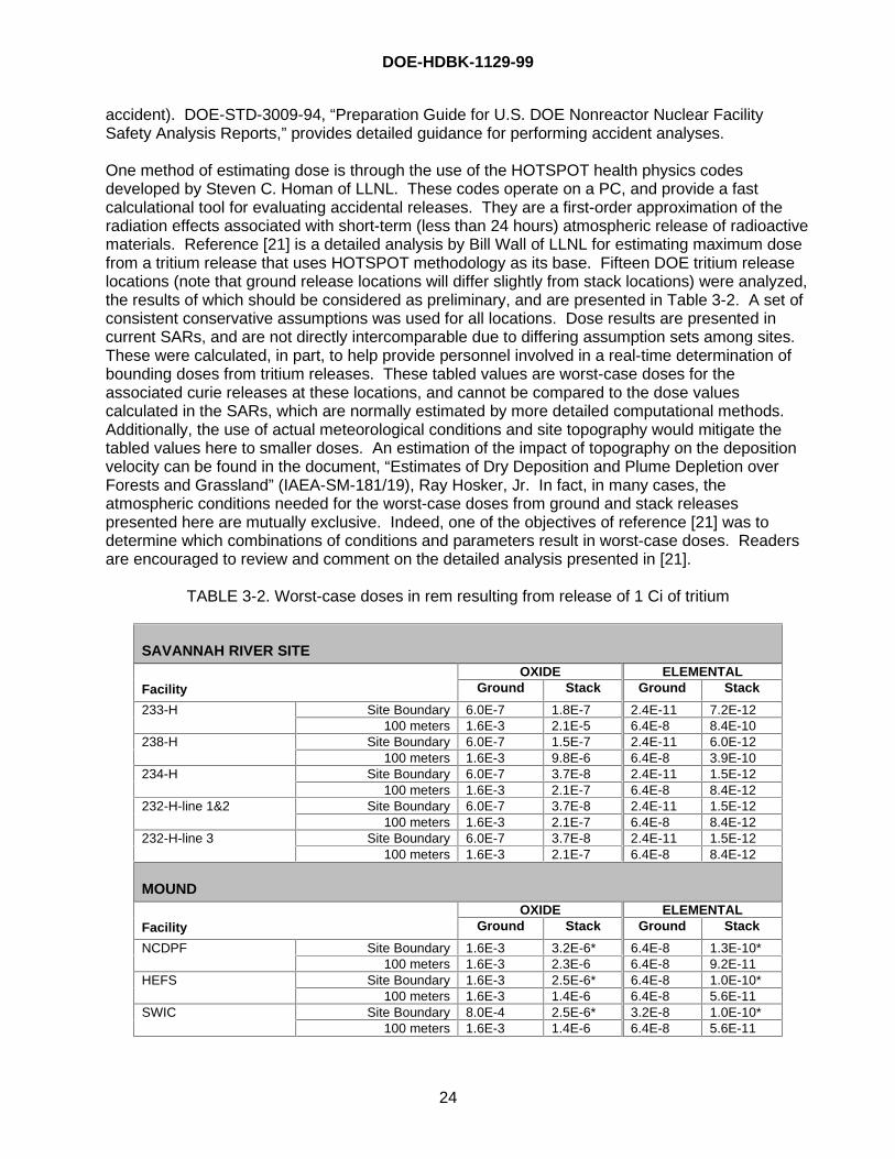
DOE-HDBK-1129-99
24
accident). DOE-STD-3009-94, “Preparation Guide for U.S. DOE Nonreactor Nuclear FacilitySafety Analysis Reports,” provides detailed guidance for performing accident analyses.
One method of estimating dose is through the use of the HOTSPOT health physics codesdeveloped by Steven C. Homan of LLNL. These codes operate on a PC, and provide a fastcalculational tool for evaluating accidental releases. They are a first-order approximation of theradiation effects associated with short-term (less than 24 hours) atmospheric release of radioactivematerials. Reference [21] is a detailed analysis by Bill Wall of LLNL for estimating maximum dosefrom a tritium release that uses HOTSPOT methodology as its base. Fifteen DOE tritium releaselocations (note that ground release locations will differ slightly from stack locations) were analyzed,the results of which should be considered as preliminary, and are presented in Table 3-2. A set ofconsistent conservative assumptions was used for all locations. Dose results are presented incurrent SARs, and are not directly intercomparable due to differing assumption sets among sites.These were calculated, in part, to help provide personnel involved in a real-time determination ofbounding doses from tritium releases. These tabled values are worst-case doses for theassociated curie releases at these locations, and cannot be compared to the dose valuescalculated in the SARs, which are normally estimated by more detailed computational methods.Additionally, the use of actual meteorological conditions and site topography would mitigate thetabled values here to smaller doses. An estimation of the impact of topography on the depositionvelocity can be found in the document, “Estimates of Dry Deposition and Plume Depletion overForests and Grassland” (IAEA-SM-181/19), Ray Hosker, Jr. In fact, in many cases, theatmospheric conditions needed for the worst-case doses from ground and stack releasespresented here are mutually exclusive. Indeed, one of the objectives of reference [21] was todetermine which combinations of conditions and parameters result in worst-case doses. Readersare encouraged to review and comment on the detailed analysis presented in [21].
TABLE 3-2. Worst-case doses in rem resulting from release of 1 Ci of tritium
SAVANNAH RIVER SITEOXIDE ELEMENTAL
Facility Ground Stack Ground Stack
Site Boundary 6.0E-7 1.8E-7 2.4E-11 7.2E-12233-H100 meters 1.6E-3 2.1E-5 6.4E-8 8.4E-10
Site Boundary 6.0E-7 1.5E-7 2.4E-11 6.0E-12238-H100 meters 1.6E-3 9.8E-6 6.4E-8 3.9E-10
Site Boundary 6.0E-7 3.7E-8 2.4E-11 1.5E-12234-H100 meters 1.6E-3 2.1E-7 6.4E-8 8.4E-12
Site Boundary 6.0E-7 3.7E-8 2.4E-11 1.5E-12232-H-line 1&2100 meters 1.6E-3 2.1E-7 6.4E-8 8.4E-12
Site Boundary 6.0E-7 3.7E-8 2.4E-11 1.5E-12232-H-line 3100 meters 1.6E-3 2.1E-7 6.4E-8 8.4E-12
MOUNDOXIDE ELEMENTAL
Facility Ground Stack Ground Stack
Site Boundary 1.6E-3 3.2E-6* 6.4E-8 1.3E-10*NCDPF100 meters 1.6E-3 2.3E-6 6.4E-8 9.2E-11
Site Boundary 1.6E-3 2.5E-6* 6.4E-8 1.0E-10*HEFS100 meters 1.6E-3 1.4E-6 6.4E-8 5.6E-11
Site Boundary 8.0E-4 2.5E-6* 3.2E-8 1.0E-10*SWIC100 meters 1.6E-3 1.4E-6 6.4E-8 5.6E-11
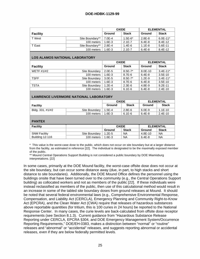
DOE-HDBK-1129-99
25
OXIDE ELEMENTALFacility Ground Stack Ground Stack
Site Boundary** 7.0E-4 1.5E-6* 2.8E-8 6.0E-11*T West100 meters 1.6E-3 2.1E-7 6.4E-8 8.4E-12
Site Boundary** 2.8E-4 1.4E-6 1.1E-8 5.6E-11T East100 meters 1.6E-3 2.1E-7 6.4E-8 8.4E-12
LOS ALAMOS NATIONAL LABORATORYOXIDE ELEMENTAL
Facility Ground Stack Ground Stack
WETF #1/#2 Site Boundary 2.0E-5 8.5E-7* 8.0E-10 3.4E-11*100 meters 1.6E-3 8.7E-6 6.4E-8 3.5E-10
TSFF Site Boundary 3.0E-5 8.5E-7* 1.2E-9 3.4E-11*100 meters 1.6E-3 8.7E-6 6.4E-8 3.5E-10
TSTA Site Boundary 1.2E-4 2.3E-6 4.8E-9 9.2E-11100 meters 1.6E-3 6.1E-6 6.4E-8 2.4E-10
LAWRENCE LIVERMORE NATIONAL LABORATORYOXIDE ELEMENTAL
Facility Ground Stack Ground Stack
Site Boundary 1.5E-4 2.8E-6 6.0E-9 1.1E-10Bldg. 331, #1/#2100 meters 1.6E-3 6.1E-6 6.4E-8 2.4E-10
PANTEX
Facility OXIDE ELEMENTALGround Stack Ground Stack
Site Boundary 1.2E-5 NA 4.8E-10 NASNM FacilityBuilding 12-116 100 meters 1.6E-3 NA 6.4E-8 NA
* This value is the worst-case dose to the public, which does not occur on site boundary but at a larger distancefrom the facility, as estimated in reference [22]. The individual is designated to be the maximally exposed memberof the public.** Mound Central Operations Support Building is not considered a public boundary by DOE Miamisburginterpretations. [22]
In some cases, primarily at the DOE Mound facility, the worst-case offsite dose does not occur atthe site boundary, but can occur some distance away (due, in part, to high stacks and shortdistance to site boundaries). Additionally, the DOE Mound Office defines the personnel using thebuildings onsite that have been turned over to the community (e.g., the Central Operations Supportbuilding) as collocated workers and not as members of the public [22]. If these individuals wereinstead reclassified as members of the public, then use of this calculational method would result inan increase in some of the tabled site boundary doses from ground releases at Mound. It shouldbe noted that several federal environmental laws (e.g., Comprehensive Environmental Response,Compensation, and Liability Act (CERCLA), Emergency Planning and Community Right-to-KnowAct (EPCRA), and the Clean Water Act (CWA) require that releases of hazardous substancesabove reportable quantities (for tritium, this is 100 curies in 24 hours) be reported to the NationalResponse Center. In many cases, the curie levels are back-calculated from offsite dose receptorrequirements (see Section 8.1.3). Current guidance from “Hazardous Substance ReleaseReporting under CERCLA, EPCRA §304, and DOE Emergency Management System/OccurrenceReporting Requirements,” DOE/EH-0383, makes a distinction between “normal” or “routine”releases and “abnormal” or “accidental” releases, and suggests reporting abnormal or accidentalreleases, even if they are below federally permitted levels.
DOE-HDBK-1129-99
26
3.3.2 Integrated Safety Management
All tritium-related operations and activities, including design, construction, system acceptance andturnover, operations, shutdown, deactivation, and decommission for Category 2 and 3 NuclearFacilities (and Category 1, if ever applicable), should follow commitments identified in DOEIntegrated Safety Management (ISM) directives of the 450.4 series, which were an outgrowth fromthe Defense Nuclear Facilities Safety Board (DNFSB) 95-2 Implementation Plan. Thecommitments for ISM follow the seven Guiding Principles:
1. Line Management Responsibility for Safety2. Clearly defined Roles and Responsibilities3. Personnel Competence Commensurate with Responsibilities4. Balance of Priorities5. Identification of Safety Standards and Requirements6. Hazard Controls Tailored to the Work Being Performed7. Operations Authorization.
The process for planning and conducting pre-work hazardous analysis for all work operations attritium facilities should be consistent with the Guiding Principles listed and should follow astructured approach commensurate with the risks and hazards involved. Several methods ofenhanced work planning and related work planning strategies used throughout the DOE complexfollow five steps: 1) Define Scope of Work, 2) Determine and Analyze Hazards, 3) Develop andImplement Controls, 4) Perform Work, and 5) Monitor Work Performed and ProvideFeedback/Improvements. This sequence is one of many ways to ensure a structured approach inwork planning with a focus on worker safety and reduced environmental risks.
3.3.3 Facility Segmentation
Facility segmentation is discussed in DOE-STD-1027-92. Activities conducted in the same facilitymay be separated into different areas for analysis purposes, but only if independence (in accidentspace) can be shown. Potential areas for segmentation include:
• Receiving area,• Receiving storage area,• Shipping area,• Shipping storage area,• Tritium unpackaging, handling, and packaging operations,• Low-level waste accumulation area,• Low-level waste packaging area, and• Packaged low-level waste storage area.
The independence of the segments, however, is not easily demonstrated. Common piping andheating, ventilation, and air conditioning (HVAC) cannot exist to use this segmentation process.Additionally, common cause initiating events (e.g., fire, seismic) affect multiple segments, therebyplacing an additional burden of proof on the analyst to demonstrate independence. A successfulsegmentation analysis, however, would not affect the applicability of Price-Anderson enforcementof the Nuclear Safety Rules to the facility.
DOE-HDBK-1129-99
27
3.4 Radiological Materials Quantity Limits
3.4.1 Tritium Shipping, Radioactive Material Inventory, Quantity Limits
Once an item has met the DOE and U.S. Department of Transportation (DOT) requirements forshipment (properly packaged, radioactively surveyed, properly marked, properly filled out shippingpapers, etc.) then the item inside the approved shipping package can be shipped to a newlocation.
During shipment, the item inside the approved shipping package is expected to be subject to thenormal activities associated with its movement from one location to another; for example, loadingand unloading the package from vehicles, transport to a shipping area, storage in the shippingarea prior to transport, loading and unloading the package onto trucks/trains/airplanes, and storagein the receiving area after arrival at the new destination.
The packaging required by DOT/NRC regulations is designed to protect the workers, the public,and the environment from the radioactive material during normal package handling, transport, andshipping/receiving storage.
The applicable requirements for various quantities of tritium for transportation and storage areroughly as follows:
• Limited Quantity (< 21.6 Ci for gas; see Table 7-1 for solids, liquids, and applicable49 CFR 173 requirements): Limited Quantities of tritium can be packaged and shipped instrong, tight containers (paper boxes, paint cans) with proper markings.
• Type A Quantity (21.6 to < 1080 Ci): Type A quantities of tritium use DOT Specification 7Acontainers, properly marked and surveyed prior to shipment. A number of different packagesare available from small cans, 55 and 85 gallon drums, 4 x 4 x 7-foot steel boxes, up to andincluding oversized, specially designed containers. These containers are relativelyinexpensive.
• Type B Quantity (> 1080 Ci): Type B quantities of tritium must be shipped in a certified DOTType B package. There is only a limited number of these expensive Type B packagesavailable for tritium shipment (e.g., UC-609, TRUPACT-II), and special routing (i.e., prescribedroutes employing highway route control such as using major highways, bypassing cities, etc.) isrequired.
• Type B Quantity, Low-Level Radioactive Waste: For the purposes of storage at the waste site,Type B quantity solid waste can be stored in Type A containers.
At the waste generation location, items containing greater than 1080 Ci quantities of tritium arenormally stored in Type A containers. These Type A containers containing over 1080 Ci mustthen be placed into Type B containers for shipping to DOE waste sites. At the DOE waste site, theType A containers can be removed from the Type B package and stored in the Type A package.This allows the expensive Type B package to be freed up to be returned to the shipper and reusedfor another Type B shipment. A radiological materials inventory must still meet the requirementsas discussed in Section 3.3.1.b.

DOE-HDBK-1129-99
28
3.4.2 Tritium Receiving Area, Shipping Area, Quantity Limits
There are no limits (other than local administrative limits) on the inventory of approved containersthat can be stored in a properly marked shipping area, receiving area, shipping storage area, andreceiving storage area. There are, however, site-wide limits that may be imposed in the EIS thatcould restrict the total inventory quantities.
These areas must be inside an area posted as a “Controlled Area.” The controlled area enclosesan area posted as a Radioactive Materials Area (RMA). The Controlled Area and the RadioactiveMaterials Area can be the same area. The RMA must be periodically surveyed and appropriatelymarked to indicate the nuclear hazard associated with the area. These areas may have more thanone incoming or outgoing certified package containing Type A or B packages waiting for transport.
3.5 Tritium Unpackaging, Handling, and Packaging Areas, Quantity Limits
The tritium is removed from the specification package/certified package in unpackaging, handlingand packaging areas, and, as such, these areas should be designated as radiological areas orHazard Category II or III nuclear facilities, depending upon the quantity of tritium in the inventory.
3.6 Tritium Waste Collection and Waste Packaging Area, Quantity Limits
The waste collection/packaging area will have, in process, the collection and packaging of low-level waste. The waste collection/packaging area should be designated as a radiological facility ornuclear facility as defined by the quantity of tritium.
3.7 Tritium Focus Group (TFG)
The TFG is comprised of both DOE federal and contractor personnel associated with tritiumoperations. It was formed in 1991 in response to the Secretary of Energy’s Task Force on tritiumoperations, and has expanded in scope and stature since that time. Its charter is contained inAppendix F. The TFG maintains a Web site (www.er.doe.gov/production/er-80/tfg), which is acomprehensive vehicle containing information on current tritium issues.
4.0 FACILITY DESIGN
DOE tritium facilities, as a subset of DOE nonreactor nuclear facilities, must conform to the designrequirements contained in DOE O 420.1, “Facility Safety.” Implementation guidance of this Ordercan be found in DOE G 420.1/B-0, and in two interim-use Guides, DOE G 420.1-X and DOE G420.1-Y.
4.1 Tritium System Philosophy
Tritium-related construction projects in the past have been designed and managed by personnelwho are qualified to design standard industrial buildings and equipment but lack experience withtritium operations. During the design and construction phase, limited use had been made of tritiumexpertise, and, after building completion, the staff must adapt the facility for tritium operations. It ismore desirable to have tritium construction projects managed by a team that includes tritium
DOE-HDBK-1129-99
29
expertise on staff. The building/systems would be designed to meet the needs of the user, andcostly retrofits after completion could be avoided.
During the first 25 years of tritium technology, the handling techniques in use were designed toprotect the worker from exposure to tritium. Worker protection was provided primarily by the use ofsingle-pass ventilation systems designed to rapidly remove any tritium released in the breathingspace from the area occupied by the workers. The ventilation gases were released through anelevated stack at high velocity to massively dilute the gases before they could reach ground level.Single-pass ventilation systems and high-velocity hoods were used extensively and quitesuccessfully for worker protection during these early years. These high-velocity ventilation, high-velocity air hood, and elevated release techniques are still used for worker protection, but generallyas a supplement to improved barriers that better protect the environment.
In those early years, the room or building enclosing the tritium activity was equipped with a single-pass ventilation system that did not recirculate the air back into the facility. Outside air wasbrought in by the ventilation fans, conditioned for comfort, passed through the building spaces onetime, and was then released to the environment through an elevated stack. The room airexchange rate generally accepted to be adequate for worker protection was 6 to 10 room airchanges per hour.
The tritium apparatus was enclosed in a high-velocity air hood, and the worker worked throughgloves in the doors or reached in through hood openings to operate the equipment. The high-velocity air hoods were maintained at a pressure negative to the room spaces, and the natural airflow was from the room through the hood opening and then out the ventilation duct work and upthe stack to the environment.
Tritium releases that occurred due to normal operations, component failure, and worker error wereinside the hood. The high-velocity air flowing through the hood swept any released tritium awayfrom the worker and out the stack to the environment where the tritium was massively diluted inconcentration. These techniques protected the worker; however, tritium was released to theenvironment.
As concern for the environment increased, tritium technologists first attempted to control releasesby increasing design and material selection requirements, adding and enforcing regulations, andincreasing worker training and awareness. Time would prove that these techniques, althoughhelpful, were not completely successful. The tritium workers were already operating at a highperformance level and the tritium releases associated with equipment design and materialselection were not measurably decreasing as a result of the more stringent design requirementsand reviews. Tritium releases continued to occur. The expectation of faultless materials anderrorless workers was unrealistic. By the late 1960s and early 1970s, it became obvious that amore realistic tritium culture was needed that better protected the worker, the public, and theenvironment. The new culture was one of capture, containment, and cleanup.
4.1.1 Tritium Capture, Contain, and Cleanup Process
The capture, contain, and cleanup process encloses the primary or first wall tritium container insidea secondary container such as a double-walled container, glovebox, room, or building so that anytritium escaping from the primary container is captured in the secondary container. A tritiumremoval system associated with the secondary container then removes the tritium from thesecondary by circulating the captured gases through a cleanup system.
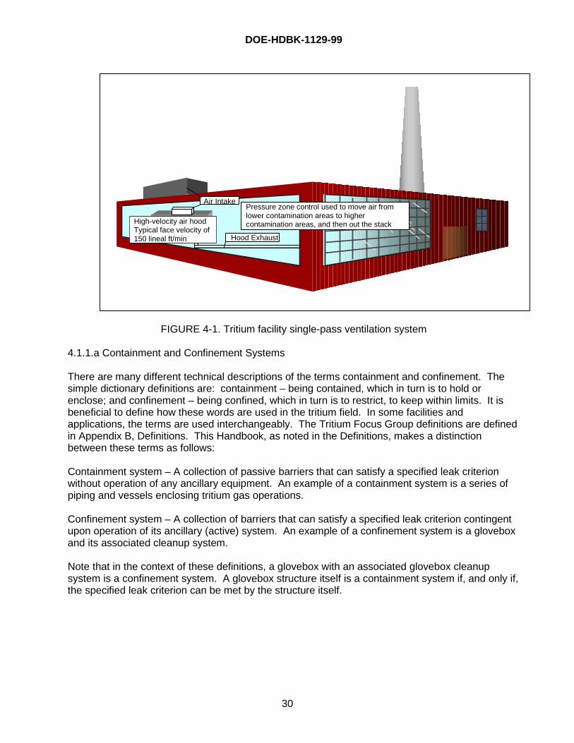
DOE-HDBK-1129-99
30
FIGURE 4-1. Tritium facility single-pass ventilation system
4.1.1.a Containment and Confinement Systems
There are many different technical descriptions of the terms containment and confinement. Thesimple dictionary definitions are: containment – being contained, which in turn is to hold orenclose; and confinement – being confined, which in turn is to restrict, to keep within limits. It isbeneficial to define how these words are used in the tritium field. In some facilities andapplications, the terms are used interchangeably. The Tritium Focus Group definitions are definedin Appendix B, Definitions. This Handbook, as noted in the Definitions, makes a distinctionbetween these terms as follows:
Containment system – A collection of passive barriers that can satisfy a specified leak criterionwithout operation of any ancillary equipment. An example of a containment system is a series ofpiping and vessels enclosing tritium gas operations.
Confinement system – A collection of barriers that can satisfy a specified leak criterion contingentupon operation of its ancillary (active) system. An example of a confinement system is a gloveboxand its associated cleanup system.
Note that in the context of these definitions, a glovebox with an associated glovebox cleanupsystem is a confinement system. A glovebox structure itself is a containment system if, and only if,the specified leak criterion can be met by the structure itself.
Air Intake
Hood Exhaust
Pressure zone control used to move air fromlower contamination areas to highercontamination areas, and then out the stackHigh-velocity air hood
Typical face velocity of150 lineal ft/min
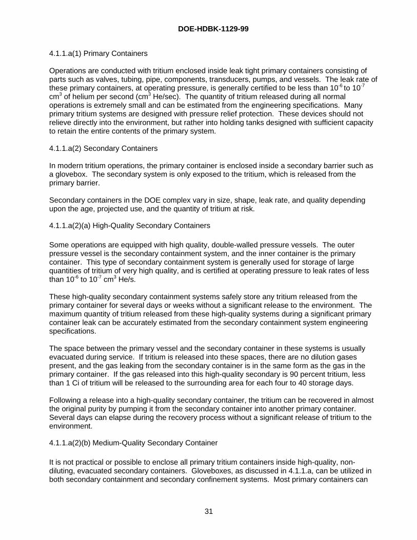
DOE-HDBK-1129-99
31
4.1.1.a(1) Primary Containers
Operations are conducted with tritium enclosed inside leak tight primary containers consisting ofparts such as valves, tubing, pipe, components, transducers, pumps, and vessels. The leak rate ofthese primary containers, at operating pressure, is generally certified to be less than 10-6 to 10-7
cm3 of helium per second (cm3 He/sec). The quantity of tritium released during all normaloperations is extremely small and can be estimated from the engineering specifications. Manyprimary tritium systems are designed with pressure relief protection. These devices should notrelieve directly into the environment, but rather into holding tanks designed with sufficient capacityto retain the entire contents of the primary system.
4.1.1.a(2) Secondary Containers
In modern tritium operations, the primary container is enclosed inside a secondary barrier such asa glovebox. The secondary system is only exposed to the tritium, which is released from theprimary barrier.
Secondary containers in the DOE complex vary in size, shape, leak rate, and quality dependingupon the age, projected use, and the quantity of tritium at risk.
4.1.1.a(2)(a) High-Quality Secondary Containers
Some operations are equipped with high quality, double-walled pressure vessels. The outerpressure vessel is the secondary containment system, and the inner container is the primarycontainer. This type of secondary containment system is generally used for storage of largequantities of tritium of very high quality, and is certified at operating pressure to leak rates of lessthan 10-6 to 10-7 cm3 He/s.
These high-quality secondary containment systems safely store any tritium released from theprimary container for several days or weeks without a significant release to the environment. Themaximum quantity of tritium released from these high-quality systems during a significant primarycontainer leak can be accurately estimated from the secondary containment system engineeringspecifications.
The space between the primary vessel and the secondary container in these systems is usuallyevacuated during service. If tritium is released into these spaces, there are no dilution gasespresent, and the gas leaking from the secondary container is in the same form as the gas in theprimary container. If the gas released into this high-quality secondary is 90 percent tritium, lessthan 1 Ci of tritium will be released to the surrounding area for each four to 40 storage days.
Following a release into a high-quality secondary container, the tritium can be recovered in almostthe original purity by pumping it from the secondary container into another primary container.Several days can elapse during the recovery process without a significant release of tritium to theenvironment.
4.1.1.a(2)(b) Medium-Quality Secondary Container
It is not practical or possible to enclose all primary tritium containers inside high-quality, non-diluting, evacuated secondary containers. Gloveboxes, as discussed in 4.1.1.a, can be utilized inboth secondary containment and secondary confinement systems. Most primary containers can
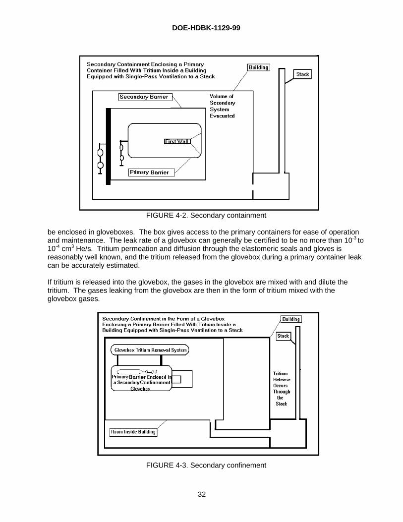
DOE-HDBK-1129-99
32
FIGURE 4-2. Secondary containment
be enclosed in gloveboxes. The box gives access to the primary containers for ease of operationand maintenance. The leak rate of a glovebox can generally be certified to be no more than 10-3 to10-4 cm3 He/s. Tritium permeation and diffusion through the elastomeric seals and gloves isreasonably well known, and the tritium released from the glovebox during a primary container leakcan be accurately estimated.
If tritium is released into the glovebox, the gases in the glovebox are mixed with and dilute thetritium. The gases leaking from the glovebox are then in the form of tritium mixed with theglovebox gases.
FIGURE 4-3. Secondary confinement
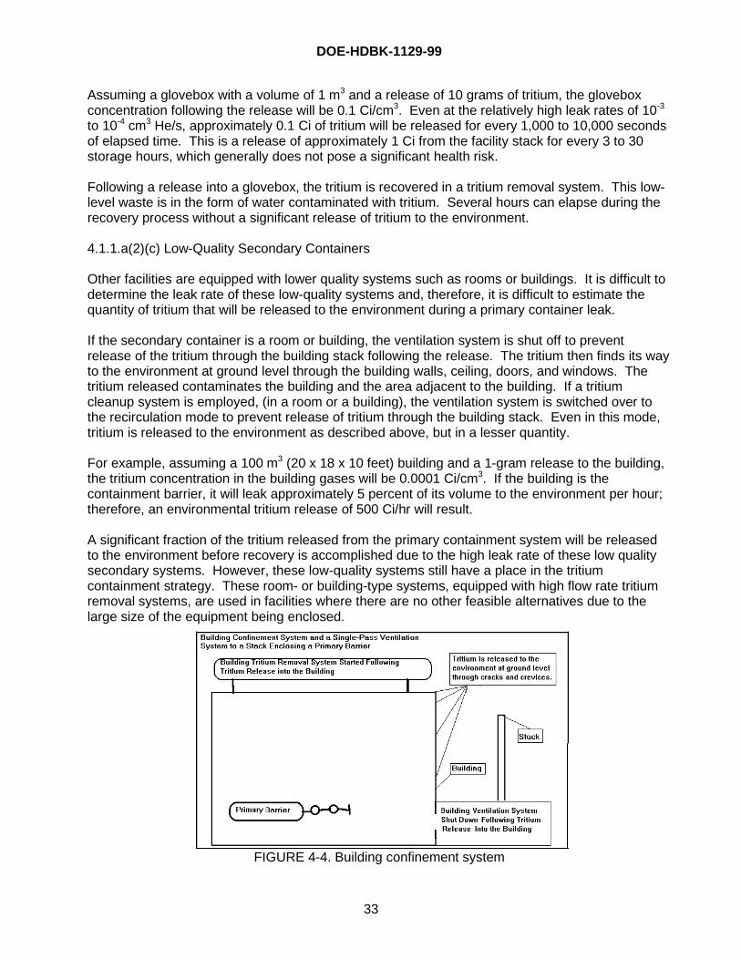
DOE-HDBK-1129-99
33
Assuming a glovebox with a volume of 1 m3 and a release of 10 grams of tritium, the gloveboxconcentration following the release will be 0.1 Ci/cm3. Even at the relatively high leak rates of 10-3
to 10-4 cm3 He/s, approximately 0.1 Ci of tritium will be released for every 1,000 to 10,000 secondsof elapsed time. This is a release of approximately 1 Ci from the facility stack for every 3 to 30storage hours, which generally does not pose a significant health risk.
Following a release into a glovebox, the tritium is recovered in a tritium removal system. This low-level waste is in the form of water contaminated with tritium. Several hours can elapse during therecovery process without a significant release of tritium to the environment.
4.1.1.a(2)(c) Low-Quality Secondary Containers
Other facilities are equipped with lower quality systems such as rooms or buildings. It is difficult todetermine the leak rate of these low-quality systems and, therefore, it is difficult to estimate thequantity of tritium that will be released to the environment during a primary container leak.
If the secondary container is a room or building, the ventilation system is shut off to preventrelease of the tritium through the building stack following the release. The tritium then finds its wayto the environment at ground level through the building walls, ceiling, doors, and windows. Thetritium released contaminates the building and the area adjacent to the building. If a tritiumcleanup system is employed, (in a room or a building), the ventilation system is switched over tothe recirculation mode to prevent release of tritium through the building stack. Even in this mode,tritium is released to the environment as described above, but in a lesser quantity.
For example, assuming a 100 m3 (20 x 18 x 10 feet) building and a 1-gram release to the building,the tritium concentration in the building gases will be 0.0001 Ci/cm3. If the building is thecontainment barrier, it will leak approximately 5 percent of its volume to the environment per hour;therefore, an environmental tritium release of 500 Ci/hr will result.
A significant fraction of the tritium released from the primary containment system will be releasedto the environment before recovery is accomplished due to the high leak rate of these low qualitysecondary systems. However, these low-quality systems still have a place in the tritiumcontainment strategy. These room- or building-type systems, equipped with high flow rate tritiumremoval systems, are used in facilities where there are no other feasible alternatives due to thelarge size of the equipment being enclosed.
FIGURE 4-4. Building confinement system
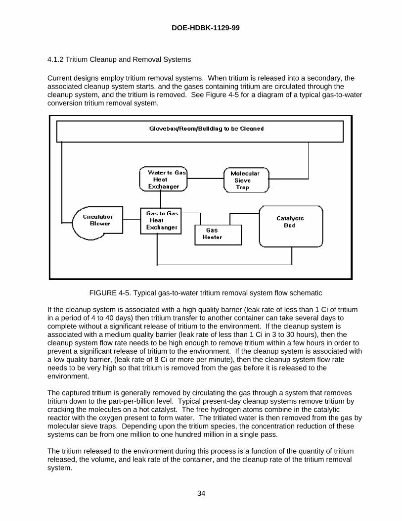
DOE-HDBK-1129-99
34
4.1.2 Tritium Cleanup and Removal Systems
Current designs employ tritium removal systems. When tritium is released into a secondary, theassociated cleanup system starts, and the gases containing tritium are circulated through thecleanup system, and the tritium is removed. See Figure 4-5 for a diagram of a typical gas-to-waterconversion tritium removal system.
FIGURE 4-5. Typical gas-to-water tritium removal system flow schematic
If the cleanup system is associated with a high quality barrier (leak rate of less than 1 Ci of tritiumin a period of 4 to 40 days) then tritium transfer to another container can take several days tocomplete without a significant release of tritium to the environment. If the cleanup system isassociated with a medium quality barrier (leak rate of less than 1 Ci in 3 to 30 hours), then thecleanup system flow rate needs to be high enough to remove tritium within a few hours in order toprevent a significant release of tritium to the environment. If the cleanup system is associated witha low quality barrier, (leak rate of 8 Ci or more per minute), then the cleanup system flow rateneeds to be very high so that tritium is removed from the gas before it is released to theenvironment.
The captured tritium is generally removed by circulating the gas through a system that removestritium down to the part-per-billion level. Typical present-day cleanup systems remove tritium bycracking the molecules on a hot catalyst. The free hydrogen atoms combine in the catalyticreactor with the oxygen present to form water. The tritiated water is then removed from the gas bymolecular sieve traps. Depending upon the tritium species, the concentration reduction of thesesystems can be from one million to one hundred million in a single pass.
The tritium released to the environment during this process is a function of the quantity of tritiumreleased, the volume, and leak rate of the container, and the cleanup rate of the tritium removalsystem.
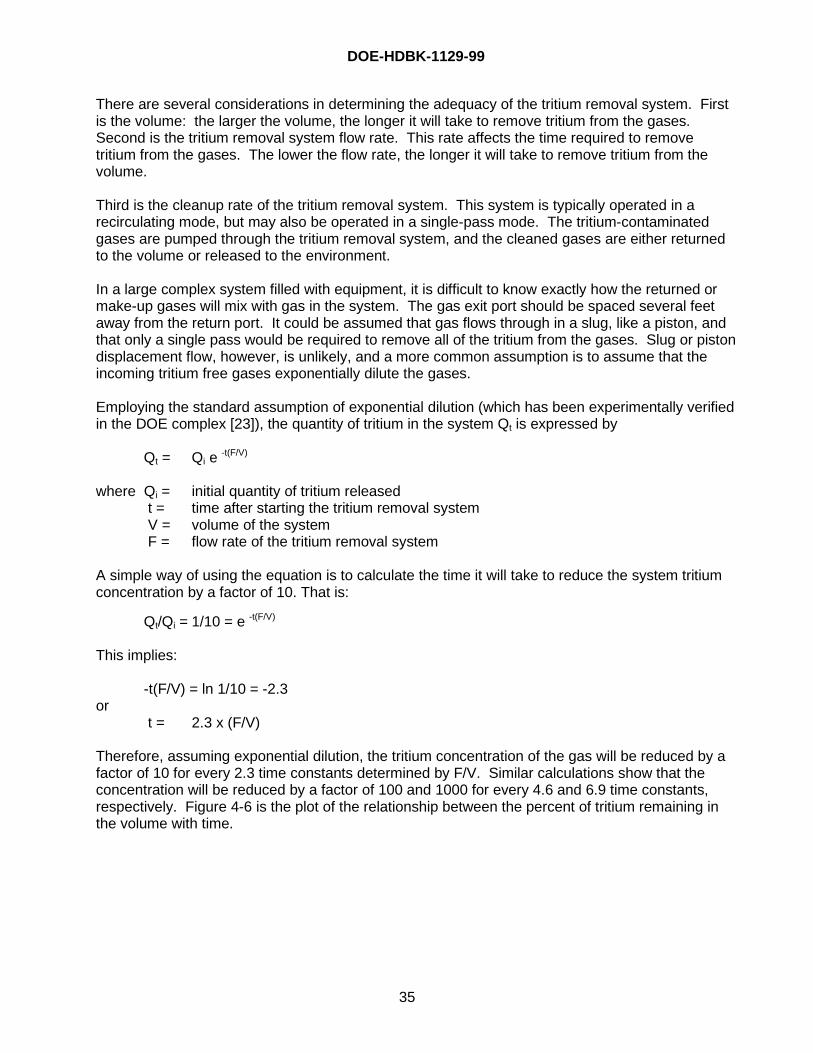
DOE-HDBK-1129-99
35
There are several considerations in determining the adequacy of the tritium removal system. Firstis the volume: the larger the volume, the longer it will take to remove tritium from the gases.Second is the tritium removal system flow rate. This rate affects the time required to removetritium from the gases. The lower the flow rate, the longer it will take to remove tritium from thevolume.
Third is the cleanup rate of the tritium removal system. This system is typically operated in arecirculating mode, but may also be operated in a single-pass mode. The tritium-contaminatedgases are pumped through the tritium removal system, and the cleaned gases are either returnedto the volume or released to the environment.
In a large complex system filled with equipment, it is difficult to know exactly how the returned ormake-up gases will mix with gas in the system. The gas exit port should be spaced several feetaway from the return port. It could be assumed that gas flows through in a slug, like a piston, andthat only a single pass would be required to remove all of the tritium from the gases. Slug or pistondisplacement flow, however, is unlikely, and a more common assumption is to assume that theincoming tritium free gases exponentially dilute the gases.
Employing the standard assumption of exponential dilution (which has been experimentally verifiedin the DOE complex [23]), the quantity of tritium in the system Qt is expressed by
Qt = Qi e -t(F/V)
where Qi = initial quantity of tritium released t = time after starting the tritium removal system V = volume of the system F = flow rate of the tritium removal system
A simple way of using the equation is to calculate the time it will take to reduce the system tritiumconcentration by a factor of 10. That is:
Qt/Qi = 1/10 = e -t(F/V)
This implies:
-t(F/V) = ln 1/10 = -2.3or
t = 2.3 x (F/V)
Therefore, assuming exponential dilution, the tritium concentration of the gas will be reduced by afactor of 10 for every 2.3 time constants determined by F/V. Similar calculations show that theconcentration will be reduced by a factor of 100 and 1000 for every 4.6 and 6.9 time constants,respectively. Figure 4-6 is the plot of the relationship between the percent of tritium remaining inthe volume with time.
DOE-HDBK-1129-99
36
0
10
20
30
40
50
60
70
80
90
100
0.00 0.30 0.60 0.90 1.20 1.50 1.80 2.10 2.40 2.70 3.00 3.30 3.60 3.90 4.20 4.50 4.80 5.10 5.40 5.70 6.00
t/(V/F) = Number of System Time Constants (F/V)
Q(i
)/Q(t
) x
100
= P
erce
nt o
f Q(i
) re
min
ing
in t
he
con
fin
emen
t vo
lum
e
Note that the quantity of tritium remaining in theconfinement volume decreases by a factor of 10for each 2.3 time constants, i.e. when t=2.3 x F/V
Q(t)=Q(i) e-t/(F/V)
FIGURE 4-6. Confinement volume cleanup rate as a function of system time constant,F/V, assuming an exponential dilution rate
The fourth consideration is the system leak rate. While the tritium removal system is in operation,some of the gases will leak out of the system to the environment. The barrier must be leak tightenough to prevent a significant release of tritium to the environment while the tritium is beingremoved. A high flow rate tritium removal system can be used to help offset a leaky system, butwill significantly increase the cost of the removal system.
The quantity of tritium released to the environment due to the leak rate can be calculated.Assuming exponential dilution, the concentration of tritium in the gas C T2(t) is
CT2(t) = CT2(i)e -t/(F/V)
where CT2(i) = initial concentration of tritium in the system t = time V = volume of the system F = flow rate of the tritium removal system
Note, CT2(i) = QT2/V where QT2 is the quantity of tritium released.
DOE-HDBK-1129-99
37
Therefore, the rate of tritium released from the system, d C
d tT 2 , at any time, t is
d C
d tT 2 = LCT2(t) = LCT2(i)e -t(F/V)
where L = leak rate of the system
The tritium release from the system due to leakage T2(rel) over any time period from 0 to t, is
T2(rel) = ∫LCT2(i)e -t(F/V) dt= (V/F) LCT2(i)e -t(F/V) |t0= (V/F) LCT2(i)e -t(F/V)
The calculated leak rate that will result in a tritium release, T2(rel), of 1 Ci due to an initial tritiumrelease, CT2(i), of 1 g (10,000 Ci) into a glovebox with a volume, V, of 1m3 and a flow rate, F, of1m3/min is
L = T 2(rel)/(V/F) CT2(i)e -t(F/V)
= 1/ (1 x 10000 x 1) = .0001 m3/min = 1.667 cm3/s
Therefore, a glovebox leak rate of 1.667 cm3/s will result in the release of 1 Ci of tritium from a1 m3 volume glovebox during the time it takes a tritium removal system operating at a flow rate of 1m3/min to clean up the glovebox following a tritium release.
4.1.3 Future Directions in Tritium Removal and Cleanup
Future tritium facilities should analyze the applicability of confinement systems in their facilities.For example, DOE O 420.1, Change 2, states, “For a specific nuclear facility, the number andarrangement of confinement barriers and their required characteristics shall be determined on acase-by-case basis. Factors that shall be considered in confinement system design shall includetype, quantity, form, and conditions for dispersing the material. Engineering evaluations, trade-offs, and experience shall be used to develop practical designs that achieve confinement systemobjectives. The adequacy of confinement systems to effectively perform the required functionsshall be documented and accepted through the Safety Analysis Report.”
As regulatory release criteria and ALARA concerns are strengthened, the desirability of barriersincreases. Most current confinement systems are of the glovebox and of the room or buildingcleanup types. One disadvantage of these current designed systems is that tritium is converted tooxide, which eventually must be handled and disposed (with the attendant risks). Room or buildingtype confinement systems are used in some tritium facilities such as in the T-building at Mound, inTFTR at Princeton Plasma Physics Laboratory, and in TSTA and WETF at Los Alamos. If thesystem is not very close to 100% efficient, the released oxide (which is ~ 25,000 times more toxicthan the gas) could give an overall detriment (e.g., if 25,000 Ci of gas are collected, but only one Ciof oxide is released by the system, the whole operation is just a draw). Some current designs,notably the cleanup systems at RTF, make use of gettering without oxidation. Additionally,research efforts for other systems that replace the oxidation step are active in the DOE complex.The primary advantage of these getter systems is that tritium is removed and stored in elemental
DOE-HDBK-1129-99
38
form and is not converted by the tritium removal system to the more radiotoxic tritiated water. Theapplication for glovebox atmospheres is good; however, severe challenges for removing tritiumfrom room atmospheres with the required flow rates, while not fouling the getters, appear lesspromising. Research into other than metal (e.g., fullerenes) gettering material has been sponsoredby EH; however, results have not been promising to date. It is possible that advances in designwill make room or building-type confinement systems highly desirable, or it may turn out that thesecleanup systems in general are found not to be cost-effective, and that a better use of resources todecrease environmental releases could be made by upgrading the existing primary and secondarysystems. Additionally, there may be future glovebox decisions in which the oxidation process isstill chosen over the gettering process due to programmatic reasons.
4.1.4 Inspection and Surveillance Requirements
Instrumentation should be provided to monitor the leak-tight integrity of process piping, tanks, andother equipment. The surveillance measurements may include those of pressure differentials orflow rates and should relate to the design leak rate. Radiation monitoring instrumentation may beused to qualitatively assess changes in leak rate.
4.2 Building Ventilation System
If tritium does penetrate its barriers, it can be released into the worker breathing space. In thisscenario, the ventilation system should be designed to meet the following objectives.
• Move released tritium from the worker breathing space as soon as possible.
• Minimize the contamination of other areas while moving released tritium.
• Release the tritium-contaminated gases at an elevation and velocity that will result in massivedilution and mixing with outside air before the tritium reaches ground level.
The ventilation system should be designed using the following guidelines:
• The ventilation system should be a single-pass ventilation system. Outside air is brought inthrough a supply fan, conditioned for the comfort of the workers, passes through the ductworkto the ventilated spaces one time, goes through the exhaust ductwork to an exhaust fan, and isreleased to the environment through the facility stack.
• The air supply and exhaust systems should be designed to eliminate dead air spaces wheretritium-contaminated gases may accumulate.
• The ventilation system ductwork should not be shared with non-tritium operations.
• To minimize cross-contamination from one room to another, the exhaust gas from each roomshould dump into a central exhaust duct. Exhaust gases from several rooms should not becombined before being dumped into the central exhaust duct.
• To minimize cross-contamination from one ventilation function to another, the gases for eachtype of function, such as room ventilation, high velocity air hood ventilation, and gloveboxventilation, from a single room should not be combined until they reach the central exhaustduct.
DOE-HDBK-1129-99
39
• To ensure good mixing and dilution by outside air, the exhaust gases should be released to theenvironment through an elevated stack at high velocity.
• The ventilation system should be designed to use pressure zone control to minimize cross-contamination. The ventilation control system is designed to hold the spaces occupied by thetritium operations at a negative pressure relative to the spaces surrounding the facility. If thewhole building is a tritium facility, then the building is at a slightly negative pressure relative tothe environment. If the tritium is in a single room in a building, the room is at a negativepressure relative to the adjacent rooms. Air continuously leaks into the tritium operating areasfrom the surrounding environment. The ventilation zones of tritium processing areas should bemaintained under controlled temperature and humidity conditions at all times to reduce the in-leakage of moisture to inert atmosphere gloveboxes. (Further reductions in inleakage ofmoisture into inert gloveboxes can be achieved by selecting a glove material that has a lowpermeation rate for moisture and by reducing the exposure time (e.g., glove port covers) and/ortotal glove surface area).
• The walls separating adjacent rooms must be reasonably sealed to minimize tritium releasedfrom contaminating an adjacent room. Administrative controls need to be in place to requirecaulking and sealing around wall penetrations such as conduit and piping.
• For the ventilation system to work as designed, the inside and outside doors and airlocks needto be used properly. Propping an outside or inside door open will upset the pressure zonecontrol system. An outside door bypasses the stack and provides a path for a ground leveltritium release. The doors should be equipped with automatic door closures, and all personnelshould be instructed on the proper use of doors.
• For facilities handling gram quantities of tritium, a rule of thumb is 6 to 10 air changes per houras the standard of performance. Depending upon the operating conditions associated with theventilated area, ventilation rates of 3 to 20 air changes per hour have been used.
The ventilation rate should be based on analysis of the hazards of the operations. A facilitythat has the potential to release only a few curies of gaseous tritium into the breathing spacedoes not need to operate at the same ventilation rate as a facility that has the potential torelease tritium into the breathing space.
• Single-pass ventilation systems are expensive to operate because all air must be conditionedto make its single pass through the facility, and this conditioned air is not reused. Additionally,a high flow rate is desired in order to remove any released tritium from the facility as soon aspossible to protect the workers.
• Special precautions such as Personnel Protective Equipment, including respiratory protectionand passing exhaust through particulate filters, are needed when working with SMTs. D&Dwork with SMTs should occur within a confined airspace, if possible.
It is feasible to design future ventilation systems to operate at a variable flow rate that is afunction of the time of day and the measured tritium concentration in the rooms. This wouldentail a higher initial cost, but would decrease the long-term operating costs without significantimpact on the facility safety.

DOE-HDBK-1129-99
40
4.3 Chilled Water System
The chilled water system that is used to cool the tritium-related activities in a facility must becarefully designed to minimize the volume and tritium concentration of the contaminated watergenerated. The use of single-wall, water-to-gas heat exchangers in tritium removal systems andvacuum furnaces for example, will result in tritium contamination of the chilled water system. Insome facilities, the same chilled water system is used to cool non-tritium activities in the samebuilding, and, at some sites, the same chilled water system is also used in non-tritium relatedactivities in adjacent buildings. As a result, tritium-contaminated wastewater is generated, andtritium contamination is spread from one piece of equipment to another, from one room to another,and from one building to another through the chilled water supply.
The chilled water system should be designed to minimize the volume of water that can becontaminated with tritium. One technique is to use water-to-water heat exchangers or double-walled, gas-flushed water-to-gas heat exchangers to isolate the high volume central system fromthe tritium-related activities. The volume of water in the secondary loop is much smaller than thatin the primary loop.
The primary reason for using chilled water for cooling equipment is cost. The systems are reliable,low in cost, small in size, readily available in many different sizes from many differentmanufacturers, and easy to maintain. Air-to-air heat exchangers can, in some cases, besubstituted for chilled water cooling, but are larger in size and will not work in some applications.Refrigerated cooling systems are more expensive, but operationally eliminate the need fordisposing of tritium-contaminated water generated by the chilled water systems.
4.4 Seismic and Wind Design and Evaluation of Structures and Facilities
Savannah River Site (SRS) has been the lead site for interfaces with the DNFSB and DOE EHconcerning NPH design issues associated with tritium. A summary of DOE Natural PhenomenaHazards Policy is included in Section 5.7.1. This policy is also applicable to structures and thecomplete facility. Section 5.7.2 and its references should be reviewed as part of the overallseismic and wind design for evaluation of a tritium facility.
For wind loading provisions, American Society of Civil Engineers (ASCE) 7-95, “Minimum DesignLoads for Buildings and Other Structures,” has recently been completed and issued and ischanged greatly from past versions. A “3-second peak wind gust” is used rather than “fastest milewind speed” as a design measure. Change Notice of DOE-STD-1020, “Natural PhenomenaHazards Design and Evaluation Criteria for Department of Energy Facilities,” is in error inreferencing ASCE 7-95, but keeping “fastest mile wind speed” as a measure. Wind speeds mustbe converted to “3-second peak wind gust” for ASCE 7-95 to be correctly used.
An understanding of the types of loading produced by earthquakes and windstorms is useful inplanning mitigating approaches. An earthquake produces shaking, which will affect the entirefacility and its contents. Attention to anchorage and connection details to all structures, systems,and components is essential. Earthquakes may also cause ground rupture if the facility is near afault. Loss of ground stability may also occur due to settlement or liquefaction and will depend onsoil types and location of the ground water table.
Windstorms generally affect the structural shell and systems and components outside of thestructure. Windstorms will produce direct pressure and suction on walls and roofs with increased
DOE-HDBK-1129-99
41
loading at corners, eaves, and ridges. Extreme windstorms can produce missiles from debris nearthe facility or from nearby facilities. These missiles can strike walls and roofs and their effectsshould be evaluated. During tornadoes, in addition to pressure effects and windborne missiles,there will be an atmospheric pressure change or a pressure drop below ambient pressure as thetornado passes over a facility. This can affect wall and roof openings and ventilation system filters.
An approach used at SRS is to store resources in a Highly Invulnerable Encased Safe (HIVES).HIVES are metal cabinets designed to store tritium reservoirs and Hydride Storage Vessels (HSV).The HIVES are designed to be capable of protecting the pressure boundary integrity of storedreservoirs or HSV against impact of structural elements free falling from the collapse of Building234-H and the adjacent 296-H stack caused by credible NPH Design Bases Accidents. TheHIVES are constructed of hardened T-1 steel, primarily from 1-inch plate. The overall dimensionsare approximately 22”Wx39”Dx68”H, which includes both a cabinet and a matching bonnetassembly bolted to the cabinet top plate. This bonnet contains an aluminum hexcall honeycombmaterial designed to absorb the impact loading stated above.
The following should be considered when designing or evaluating structures or facilities forearthquakes and windstorms:
• The Performance Category (PC) of the structure or facility should be determined. It is notnecessary for the entire facility to have the same PC; that is, different parts of a facility could bein different performance categories. For example the office portion of a Tritium HandlingFacility may be PC1 while the laboratory portion may be PC3.
• Judgment should be exercised to ensure that various parts of the facility have beencategorized in a rational manner. For example, a PC1 facility does not physically support aPC3 facility.
• In addition to the vertical load carrying system, a lateral force resisting system should carry theseismic and wind loads. This may be a frame or shear wall system or separate bracingsystem. Attention to connection details is very important in ensuring adequate structuralintegrity to resist the limited energy input motion produced by earthquakes and the longerduration wind loading.
• An understanding of the type of loading that earthquakes and extreme winds produce on theoverall structure is essential during the design and evaluation process.
• An adequate load path must be ensured throughout the structure— Roof and wall connection details to structural system— Overall roof-to-wall connections— Wall-to-foundation connections— Foundation adequacy
• Innovative technologies, such as base isolation and passive energy dissipation devices, shouldbe considered during design of new facilities and for upgrading of existing facilities to reduceseismic loads to systems and equipment within the structure. These approaches have beenused in many projects throughout the world during the last 10 years.
• Avoid the type of details and structural features that have performed poorly during pastearthquakes. These are as follows:
DOE-HDBK-1129-99
42
Structural Systems— Unreinforced masonry construction— Non-ductile concrete construction— “Soft” story construction— Incomplete lateral force resisting systems— Welded steel connections— Irregularities, eccentricities, and discontinuities in both weight and geometry— Pounding or impact with nearby facilities
Details— Inadequate hoop reinforcement in concrete columns— Reinforcing steel connections— Connection details— Accommodation of differential motion
• Ensure foundation adequacy by avoiding the following:— Ground failures— Landslides— Liquefaction— Excessive or differential settlement
• Ensure that lifelines are not damaged.— Provide flexibility in lifeline connections to the facility.— Identify important lifeline functions such as power, water, sewer, gas, and
communications that will be needed immediately after an earthquake or windstorm.— Examine the vulnerability of lifelines onsite as well as offsite.— Plan for alternative lifeline support.
• Examine and prepare for the possibility of a fire following the earthquake.
Employing mitigation efforts before earthquakes or windstorms occur is a very cost-effectivemeans to provide life safety, to minimize damage and losses, and to reduce the impact on thefacility and operations. It is extremely important to pay attention to all details because naturalphenomena will find the weak links and cause damage.
4.5 Other Design Considerations
The following items should be considered in the design of a facility with tritium operations.
• Designated safety-class systems should employ the concepts of redundancy, separation, anddiversity. Some designs in the past, notably at Building 233-H at SRS (i.e., RTF), employedredundant signals to a single actuation device. An improvement to this design concept wouldbe to provide these redundant signals to two independent, separate (by distance) actuationdevices.
• A design requirement should be included to prevent the formation of explosive mixtures duringthe handling, processing, and storage of tritium gas and other hydrogen isotopes.
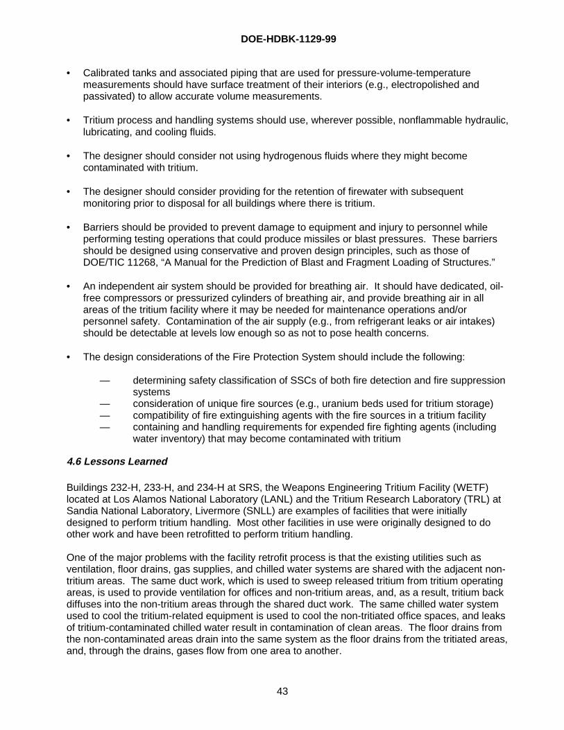
DOE-HDBK-1129-99
43
• Calibrated tanks and associated piping that are used for pressure-volume-temperaturemeasurements should have surface treatment of their interiors (e.g., electropolished andpassivated) to allow accurate volume measurements.
• Tritium process and handling systems should use, wherever possible, nonflammable hydraulic,lubricating, and cooling fluids.
• The designer should consider not using hydrogenous fluids where they might becomecontaminated with tritium.
• The designer should consider providing for the retention of firewater with subsequentmonitoring prior to disposal for all buildings where there is tritium.
• Barriers should be provided to prevent damage to equipment and injury to personnel whileperforming testing operations that could produce missiles or blast pressures. These barriersshould be designed using conservative and proven design principles, such as those ofDOE/TIC 11268, “A Manual for the Prediction of Blast and Fragment Loading of Structures.”
• An independent air system should be provided for breathing air. It should have dedicated, oil-free compressors or pressurized cylinders of breathing air, and provide breathing air in allareas of the tritium facility where it may be needed for maintenance operations and/orpersonnel safety. Contamination of the air supply (e.g., from refrigerant leaks or air intakes)should be detectable at levels low enough so as not to pose health concerns.
• The design considerations of the Fire Protection System should include the following:
— determining safety classification of SSCs of both fire detection and fire suppressionsystems
— consideration of unique fire sources (e.g., uranium beds used for tritium storage)— compatibility of fire extinguishing agents with the fire sources in a tritium facility— containing and handling requirements for expended fire fighting agents (including
water inventory) that may become contaminated with tritium
4.6 Lessons Learned
Buildings 232-H, 233-H, and 234-H at SRS, the Weapons Engineering Tritium Facility (WETF)located at Los Alamos National Laboratory (LANL) and the Tritium Research Laboratory (TRL) atSandia National Laboratory, Livermore (SNLL) are examples of facilities that were initiallydesigned to perform tritium handling. Most other facilities in use were originally designed to doother work and have been retrofitted to perform tritium handling.
One of the major problems with the facility retrofit process is that the existing utilities such asventilation, floor drains, gas supplies, and chilled water systems are shared with the adjacent non-tritium areas. The same duct work, which is used to sweep released tritium from tritium operatingareas, is used to provide ventilation for offices and non-tritium areas, and, as a result, tritium backdiffuses into the non-tritium areas through the shared duct work. The same chilled water systemused to cool the tritium-related equipment is used to cool the non-tritiated office spaces, and leaksof tritium-contaminated chilled water result in contamination of clean areas. The floor drains fromthe non-contaminated areas drain into the same system as the floor drains from the tritiated areas,and, through the drains, gases flow from one area to another.
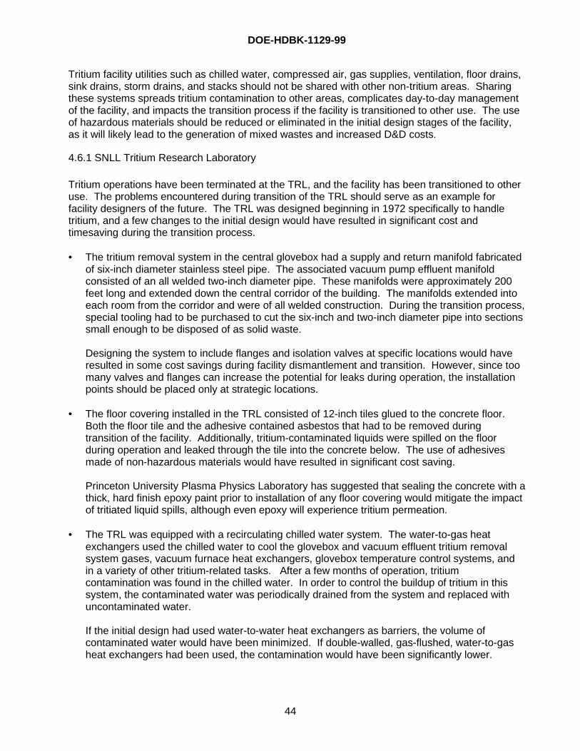
DOE-HDBK-1129-99
44
Tritium facility utilities such as chilled water, compressed air, gas supplies, ventilation, floor drains,sink drains, storm drains, and stacks should not be shared with other non-tritium areas. Sharingthese systems spreads tritium contamination to other areas, complicates day-to-day managementof the facility, and impacts the transition process if the facility is transitioned to other use. The useof hazardous materials should be reduced or eliminated in the initial design stages of the facility,as it will likely lead to the generation of mixed wastes and increased D&D costs.
4.6.1 SNLL Tritium Research Laboratory
Tritium operations have been terminated at the TRL, and the facility has been transitioned to otheruse. The problems encountered during transition of the TRL should serve as an example forfacility designers of the future. The TRL was designed beginning in 1972 specifically to handletritium, and a few changes to the initial design would have resulted in significant cost andtimesaving during the transition process.
• The tritium removal system in the central glovebox had a supply and return manifold fabricatedof six-inch diameter stainless steel pipe. The associated vacuum pump effluent manifoldconsisted of an all welded two-inch diameter pipe. These manifolds were approximately 200feet long and extended down the central corridor of the building. The manifolds extended intoeach room from the corridor and were of all welded construction. During the transition process,special tooling had to be purchased to cut the six-inch and two-inch diameter pipe into sectionssmall enough to be disposed of as solid waste.
Designing the system to include flanges and isolation valves at specific locations would haveresulted in some cost savings during facility dismantlement and transition. However, since toomany valves and flanges can increase the potential for leaks during operation, the installationpoints should be placed only at strategic locations.
• The floor covering installed in the TRL consisted of 12-inch tiles glued to the concrete floor.Both the floor tile and the adhesive contained asbestos that had to be removed duringtransition of the facility. Additionally, tritium-contaminated liquids were spilled on the floorduring operation and leaked through the tile into the concrete below. The use of adhesivesmade of non-hazardous materials would have resulted in significant cost saving.
Princeton University Plasma Physics Laboratory has suggested that sealing the concrete with athick, hard finish epoxy paint prior to installation of any floor covering would mitigate the impactof tritiated liquid spills, although even epoxy will experience tritium permeation.
• The TRL was equipped with a recirculating chilled water system. The water-to-gas heatexchangers used the chilled water to cool the glovebox and vacuum effluent tritium removalsystem gases, vacuum furnace heat exchangers, glovebox temperature control systems, andin a variety of other tritium-related tasks. After a few months of operation, tritiumcontamination was found in the chilled water. In order to control the buildup of tritium in thissystem, the contaminated water was periodically drained from the system and replaced withuncontaminated water.
If the initial design had used water-to-water heat exchangers as barriers, the volume ofcontaminated water would have been minimized. If double-walled, gas-flushed, water-to-gasheat exchangers had been used, the contamination would have been significantly lower.
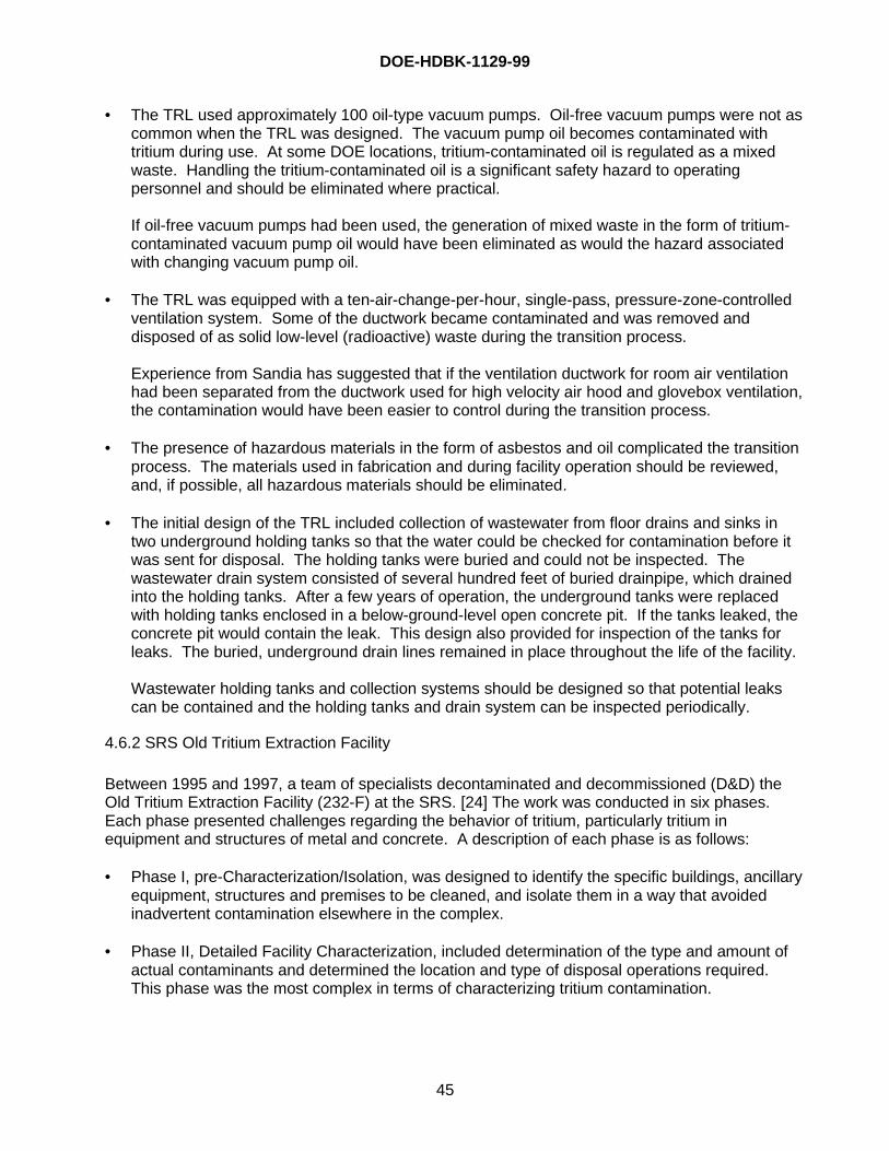
DOE-HDBK-1129-99
45
• The TRL used approximately 100 oil-type vacuum pumps. Oil-free vacuum pumps were not ascommon when the TRL was designed. The vacuum pump oil becomes contaminated withtritium during use. At some DOE locations, tritium-contaminated oil is regulated as a mixedwaste. Handling the tritium-contaminated oil is a significant safety hazard to operatingpersonnel and should be eliminated where practical.
If oil-free vacuum pumps had been used, the generation of mixed waste in the form of tritium-contaminated vacuum pump oil would have been eliminated as would the hazard associatedwith changing vacuum pump oil.
• The TRL was equipped with a ten-air-change-per-hour, single-pass, pressure-zone-controlledventilation system. Some of the ductwork became contaminated and was removed anddisposed of as solid low-level (radioactive) waste during the transition process.
Experience from Sandia has suggested that if the ventilation ductwork for room air ventilationhad been separated from the ductwork used for high velocity air hood and glovebox ventilation,the contamination would have been easier to control during the transition process.
• The presence of hazardous materials in the form of asbestos and oil complicated the transitionprocess. The materials used in fabrication and during facility operation should be reviewed,and, if possible, all hazardous materials should be eliminated.
• The initial design of the TRL included collection of wastewater from floor drains and sinks intwo underground holding tanks so that the water could be checked for contamination before itwas sent for disposal. The holding tanks were buried and could not be inspected. Thewastewater drain system consisted of several hundred feet of buried drainpipe, which drainedinto the holding tanks. After a few years of operation, the underground tanks were replacedwith holding tanks enclosed in a below-ground-level open concrete pit. If the tanks leaked, theconcrete pit would contain the leak. This design also provided for inspection of the tanks forleaks. The buried, underground drain lines remained in place throughout the life of the facility.
Wastewater holding tanks and collection systems should be designed so that potential leakscan be contained and the holding tanks and drain system can be inspected periodically.
4.6.2 SRS Old Tritium Extraction Facility
Between 1995 and 1997, a team of specialists decontaminated and decommissioned (D&D) theOld Tritium Extraction Facility (232-F) at the SRS. [24] The work was conducted in six phases.Each phase presented challenges regarding the behavior of tritium, particularly tritium inequipment and structures of metal and concrete. A description of each phase is as follows:
• Phase I, pre-Characterization/Isolation, was designed to identify the specific buildings, ancillaryequipment, structures and premises to be cleaned, and isolate them in a way that avoidedinadvertent contamination elsewhere in the complex.
• Phase II, Detailed Facility Characterization, included determination of the type and amount ofactual contaminants and determined the location and type of disposal operations required.This phase was the most complex in terms of characterizing tritium contamination.
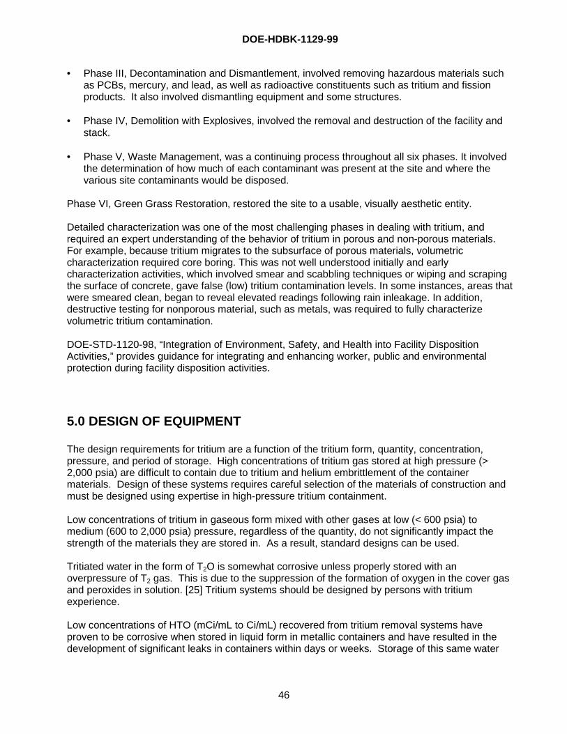
DOE-HDBK-1129-99
46
• Phase III, Decontamination and Dismantlement, involved removing hazardous materials suchas PCBs, mercury, and lead, as well as radioactive constituents such as tritium and fissionproducts. It also involved dismantling equipment and some structures.
• Phase IV, Demolition with Explosives, involved the removal and destruction of the facility andstack.
• Phase V, Waste Management, was a continuing process throughout all six phases. It involvedthe determination of how much of each contaminant was present at the site and where thevarious site contaminants would be disposed.
Phase VI, Green Grass Restoration, restored the site to a usable, visually aesthetic entity.
Detailed characterization was one of the most challenging phases in dealing with tritium, andrequired an expert understanding of the behavior of tritium in porous and non-porous materials.For example, because tritium migrates to the subsurface of porous materials, volumetriccharacterization required core boring. This was not well understood initially and earlycharacterization activities, which involved smear and scabbling techniques or wiping and scrapingthe surface of concrete, gave false (low) tritium contamination levels. In some instances, areas thatwere smeared clean, began to reveal elevated readings following rain inleakage. In addition,destructive testing for nonporous material, such as metals, was required to fully characterizevolumetric tritium contamination.
DOE-STD-1120-98, “Integration of Environment, Safety, and Health into Facility DispositionActivities,” provides guidance for integrating and enhancing worker, public and environmentalprotection during facility disposition activities.
5.0 DESIGN OF EQUIPMENT
The design requirements for tritium are a function of the tritium form, quantity, concentration,pressure, and period of storage. High concentrations of tritium gas stored at high pressure (>2,000 psia) are difficult to contain due to tritium and helium embrittlement of the containermaterials. Design of these systems requires careful selection of the materials of construction andmust be designed using expertise in high-pressure tritium containment.
Low concentrations of tritium in gaseous form mixed with other gases at low (< 600 psia) tomedium (600 to 2,000 psia) pressure, regardless of the quantity, do not significantly impact thestrength of the materials they are stored in. As a result, standard designs can be used.
Tritiated water in the form of T2O is somewhat corrosive unless properly stored with anoverpressure of T2 gas. This is due to the suppression of the formation of oxygen in the cover gasand peroxides in solution. [25] Tritium systems should be designed by persons with tritiumexperience.
Low concentrations of HTO (mCi/mL to Ci/mL) recovered from tritium removal systems haveproven to be corrosive when stored in liquid form in metallic containers and have resulted in thedevelopment of significant leaks in containers within days or weeks. Storage of this same water
DOE-HDBK-1129-99
47
solidified on clay or on molecular sieve material, regardless of the quantity, is stable and non-corrosive and may be stored for many years in the container.
5.1 Material Compatibility
Proper materials selection and rigorous design have led to tritium-handling systems that areextremely safe for long periods of time. Materials exposed to tritium under certain conditions canbe susceptible to hydrogen embrittlement. The chances of embrittlement are significantly reducedby proper material selection. No additional thickness of components, such as the “corrosionallowance” used to mitigate uniform corrosion, is added to components to reduce or eliminate thechance of hydrogen-induced cracking and subsequent failure as material degradation effects arenot uniform. In the past, tritium systems were located in hood systems having a single-pass airflow to protect workers should a component fail and tritium be released; the released tritium wouldbe removed from the facility into the atmosphere by the hood exhaust system. Current systemdesign normally consists of a closed glovebox, with a stripper or getter system to trap the releasedtritium. This arrangement protects workers and prevents releases to the environment.
Tritium can permeate vessel barriers, especially in components operating at elevated temperature.Currently available tritium permeation data is normally sufficient to estimate the order of magnitudeof tritium permeation through barriers. These estimates can be used during system design or todetermine whether additional purging and stripping systems are required to “clean up” permeatedtritium or whether other design changes (such as wall thickness, material, or coating) are requiredto reduce permeation. Tritium permeation can lead not only to contamination outside the barrier,but it can also result in significant quantities of tritium being dissolved in parts, which can lead tohydrogen embrittlement. Over time, this tritium decays to 3He, which has been found toaccentuate hydrogen embrittlement and to cause weld cracking (see below).
5.1.1 System Design
Tritium primary containers must have an exceptionally low leak rate (10-6 to 10-7 cm3 4He/second)and probability of failure or leaking. The consequences of tritium leaks can include personneluptake, release to the environment, ignition (if mixed with oxygen), and violation of operatingpermits. Pressure and vacuum vessels used in tritium systems are generally designed andconstructed using codes and standards applicable to boiler and pressure vessels. In the UnitedStates, use of the American Society of Mechanical Engineers (ASME) Boiler and Pressure VesselCode is recommended but not required. Pressure and vacuum vessels constructed using thiscode have an accepted rigor in design, construction, and inspection that facilitates approval andacceptance by regulators. The ASME Boiler and Pressure Vessel Code primarily covers thedesign of vessels, and does not cover all of the aspects of a tritium system design. Other designstandards, such as resistance to seismic events, also must be followed, depending on the locationand regulators of the facility. See Sections 4.4 and 5.7 for more discussion of seismic design.
5.1.1.a Leak Testing
After fabrication, thoroughly leak testing tritium systems is extremely important. Normally, leaktesting employs commercial helium-mass-spectrometer-based systems and is performed after anyother required proof, pressure, or vacuum performance tests. Other leak detection methods, suchas rate-of-rise, can also be employed in addition to helium mass spectrometry. A dilute solution oftritium in an inert gas can also be used to detect small leaks. Tritium is a highly effective leak
DOE-HDBK-1129-99
48
detection species, since it travels rapidly through cracks and can be easily detected at very lowlevels.
5.1.1.b Joining
Components of tritium systems are commonly joined by welding. Welds are normally designed sothey can be non-destructively inspected by a suitable method such as radiography or ultrasonictesting. Also, the weld design should minimize so-called “virtual leaks” on the interior of tritiumcontaining volumes. Examples of weld practices to minimize virtual leaks include 1) using fullpenetration welds where possible, and 2) welding feed-throughs to the interior wall surface (not onthe outside, which would leave a gap on the inside around the feed-through that is difficult tooutgas). Standard weld rod filler materials are chosen, depending on the base alloy. Every effortshould be made to reduce or eliminate welding residual stresses.
There is less experience using other joining methods such as brazing or high temperaturesoldering in tritium systems. Dissimilar materials may have to be joined by a transition junction,using an intermediate material to enable proper welding and accommodate differences in thermalexpansion and other properties.
Tritium gas permeates austenitic stainless steels, and, over time, 3He is created by beta decay oftritium in solution in the material. Welding stainless steel containing solute helium is difficultbecause intergranular cracking can occur. During welding, the solute helium agglomerates atgrain boundaries and forms both intergranular cracks in the heat-affected zone and pores in thefusion zone. Low-heat-input weld techniques have been shown to mitigate this problem to somedegree; however, weld repair of helium-containing stainless steel is normally difficult to performwithout some cracking.
All-metal mechanical joints are also a sound way to join components in tritium systems. Typically,copper, silver-plated nickel, or silver-plated stainless steel have been used as gaskets.Commercial high- and ultrahigh- vacuum fittings are normally compatible with tritium.
5.1.1.c Surface Coatings and Treatments
Aluminum and aluminide coatings have been successfully employed on stainless steel to reducepermeation into and through the steel. These coatings can be applied on large items using aproprietary fluidized bed furnace, having a controlled atmosphere (in the so-called “calorization”process). Gold has also been used as a permeation barrier in some applications and is oftenapplied over a thin nickel buffer layer (“strike”) that has been applied to the bulk metal (e.g.,stainless steel) after proper surface preparation.
Several companies treat stainless steel surfaces using various proprietary electrochemicalprocesses to “passivate” the surface. These processes probably enrich the chrome content of thesurface oxide, polish the surface (thereby reducing the effective surface area), and remove carbonand hydrogen from near the surface. All of these microstructural changes may be desirable fortritium systems in which the process gas must remain at high purity. Capillary lines that route gasto mass spectrometers are commonly passivated, to reduce changes of gas composition byisotope exchange, while the gas flows from the sample location to the mass spectrometer.Passivated surfaces reduce the rate of isotope exchange in hydrogen isotope mixtures, probablyby reducing the catalytic effect of the surface decomposing hydrogen isotope molecules to atoms,which enables isotope exchange. Vacuum systems having surfaces treated in this way evacuate
DOE-HDBK-1129-99
49
faster. This type of surface passivation can be expensive, so many parts of tritium systems are notpassivated; normally only parts requiring the special properties of passivated surfaces are treated.
5.1.2 Structural Metals
Exposure of metals to high pressure (> 2,000 psia) hydrogen, deuterium, or tritium will result inhydrogen embrittlement of the material. This could eventually result in material failure. The timeuntil failure is a function of the container material, the pressure, and temperature. Additionally,materials exposed to high-pressure tritium are also subject to helium embrittlement. Tritium at highpressure enters the metal and decays to 3He. The buildup of helium in the metal results in heliumembrittlement, which, depending upon the pressure, temperature, and type of material, willeventually result in failure of the material. Exposure of metals to low to medium pressure tritium atnormal temperatures does not generally result in material failure within any reasonable period oftime.
Some metals are more resistant to embrittlement than others and, therefore, are more compatiblewith tritium. Depending upon the specific application, 304L and 316L stainless steel are generallyconsidered to be the most hydrogen compatible and readily available stainless steels for tritiumservice. High-pressure vessels, valves, and tubing designed of these materials when used at theirrated pressure and temperature will provide many years of service without material failure. Whenequipment is designed for tritium operations, a materials expert should be consulted to ensure thatthe materials selected are compatible with their intended service.
5.1.2.a Austenitic Stainless Steels
The recommended materials of construction for tritium-handling systems are from the class ofwrought 3XX series of austenitic (face-centered-cubic) stainless steels, including Types 304L,316L, and 347. Types 304L and 316L are most often used in tritium processing systems. Thesesteels provide good strength, weldability and resistance to hydrogen embrittlement. Componentsfabricated from these materials are procured routinely. Many commercially available vacuumsystem components that are used in tritium systems, such as valves, piping, pumps, and analyticalinstrument sensors, are fabricated from these types of austenitic stainless steel. Wroughtmaterials are preferred to cast because wrought materials normally have a more homogenousmicrostructure. In the past, tritium has leaked through parts having poorly oriented stringers andinclusions. The forging direction of some wrought components has been specified so that theorientation of inclusions is not in a direction that could result in a tritium leak path. Low carbongrades (such as 304L and 316L) are preferred to avoid weld sensitization and to reduce thenumber of inclusions (impurity particles such as oxides and carbides). Modern vacuum-arc-remelted steels are a good choice because they have lower impurity levels, thereby resulting infewer inclusions that could aid hydrogen-induced cracking or provide leak paths. Typically, tritiumsystem components employ seamless pipe and tube where practical.
Stabilized grades, such as Type 347, have been employed in applications where post-weld heattreatment is not possible. This usually occurs when a process vessel contains a working material(such as hydride or getter) that will degrade when exposed to the post-weld heat treatment, whichis typically performed at about 1,100°C for austenitic stainless steels.
High carbon grades, such as Type 347H or Type 316H (having 0.04 percent carbon minimum),have been successfully employed for tritium service if high temperature strength is required. Type347H is employed in the Hydride Transport Vessel (see section 6.2.2), and Type 316H was
DOE-HDBK-1129-99
50
employed for the SRS Building 232-H Extraction Furnace retorts. Type 310 stainless steel hasgood oxidation resistance and can be considered for elevated temperature applications if oxidationis a concern. Type 316 stainless has superior creep resistance but inferior oxidation resistance toType 310.
Some types of higher-strength austenitic stainless steels not generally employed for tritium servicemay be required for fasteners (such as nuts and bolts) in mechanical joints in high-temperatureregions. This may be acceptable if the bolts are exposed to only residual amounts of tritium.These materials also may be used to contact 3XX stainless steels to avoid galling of mating screwcontact surfaces. Typical materials used in these applications include Nitronic 60, Nitronic 50 (alsocalled 21-13-9) and Nitronic 40 (also called 21-6-9); these are all nitrogen-strengthened austeniticstainless steels.
5.1.2.b Copper and Copper Alloys
In principle, copper should be a suitable material in tritium systems. Copper has several tritium-compatible properties. Tritium has a low permeability in copper, and copper is a ductile, stable,face-centered-cubic metal and so is resistant to hydrogen embrittlement. The high thermalconductivity of copper is a desirable property for process vessels requiring heat flow or constanttemperature. Copper can be easily joined in a number of ways (e.g. soldering, brazing, welding).In spite of these advantageous properties, copper and copper alloys are not commonly used intritium systems. Several factors may account for this. The ASME allowable design strength ofcopper falls rapidly at temperatures above 200 °C, making it difficult to use copper for processbeds that operate at elevated temperature. Also, hydrogen isotopes can react at elevatedtemperature with oxygen in copper, whether the oxygen is in solid solution or in copper oxideprecipitates. In either case, water is formed, and over time water vapor agglomerates at grainboundaries, which eventually results in intergranular cavitation, cracking, and failure. This failuremechanism is sometimes termed “steam embrittlement.” Also, a transition junction (normallynickel) is required to join copper and the stainless steel components of the remainder of thesystem.
5.1.2.c Aluminum and Aluminum Alloys
Aluminum has properties making it potentially desirable for tritium systems. It has a low densityand a high thermal conductivity. Hydrogen isotope permeability is very low in aluminum comparedto stainless steel. Aluminum is used in applications where light weight is important, such as incontainers that must be lifted by personnel in gloveboxes. However, aluminum is not commonlyused in tritium systems. Stainless steel has much higher strength, at room and elevatedtemperature. Welding aluminum requires more precautions because aluminum reacts withatmospheric water vapor, which can cause porosity due to hydrogen in the weld fusion zone.
5.1.2.d Materials to Avoid
Plain carbon steels and alloy steels must not be used for tritium service. These steels have highstrength and (normally) a body-centered-cubic crystal structure, both of which make the materialless ductile and much more susceptible to hydrogen embrittlement. Ferritic stainless steels (suchas Type 430), martensitic stainless steels (both quench-and-tempered (such as Type 410) andprecipitation hardening (such as 17-4 PH and PH 13-8 MO)) and precipitation hardened austeniticstainless steels (such as AM-350) should not be used for general tritium service; they are all more
DOE-HDBK-1129-99
51
susceptible to hydrogen embrittlement than the austenitic stainless steels. Additionally, free-machining grades of austenitic stainless steel (such as Type 303) should not be used.
Other materials that must not be used for tritium service are any material that forms hydride nearroom temperature and atmospheric pressure. Examples include zirconium, tantalum, niobium, andmany alloys of these materials.
5.1.3 Polymers
All polymers degrade when exposed to radiation. Both tritium and tritiated water permeate allpolymers, and permeated tritium deposits the beta decay energy throughout the polymer bulk.(Although the tritium beta energy is very low and has a small penetration depth in matter,permeation allows tritium atoms to be near enough to polymer chains throughout the bulk to causechanges in the polymer by radiation.) Types of radiation-induced changes in polymer propertiesinclude either softening (degradation) or hardening, ductility loss, color change, dimensionalchange, and gas evolution. Because of these effects, polymers should only be used in tritiumsystems where no metal alternatives exist. Normally, only polymers that harden during radiationexposure are employed, and are replaced before they begin to deteriorate. In addition to polymerbreakdown itself, products of degradation can form corrosive liquids or acids such as HF and HCl.Polymer parts must be easily replaceable as a part of normal operations, and a program of regularinspection and replacement should be established. The system should be designed to expose anypolymers to as little tritium as possible. Typical uses of polymers in gas-handling systems includegaskets, O-rings, electrical cable insulation and valve parts, including seats, stem tips, andpacking.
Polymers relatively resistant to radiation can typically withstand up to about 1 million rad (1 rad =100 erg energy deposited per gram of material). By knowing the solubility of tritium in a polymer ata given temperature and tritium partial pressure and the decay rate of tritium, the approximatedose can be calculated, assuming the tritium concentration has reached equilibrium.
Many effects of radiation on polymers are accentuated by oxygen. Protecting polymers fromoxygen or air will likely lengthen the lifetime of polymers exposed to tritium. Also, temperaturesabove about 120°C accelerate radiation effects in polymers, so the temperature of any polymerparts should be kept as low as possible. Inert additives such as glass or graphite generallyenhance the resistance of polymers to radiation. Addition of antioxidants may also enhanceradiation resistance.
5.1.3.a Plastics
VespelTM, a polyamide, has been successfully used for valve stem tips in some tritium laboratories.Ultra-High-Molecular-Weight polyethylene (UHMWPE) and High Density Polyethylene (HDPE)have been used for valve stem tips in automatic valves. Quantitative data still needs to beaccumulated on the effectiveness of all of these materials. Success as a stem tip material,particularly UHMWPE and HDPE, have been overstated in the past as described in EH TechnicalNotice 94-01, “Guidelines for Valves in Tritium Service.”
Low-Density polyethylene (LDPE) is very permeable by tritium and tritiated water and should notbe considered for use in tritium systems. Polytetrafluoroethylene (PTFE, a trade name is TeflonTM)degrades and decomposes in tritium, thus resulting in HF and HCl. In humid air, hydrochloric andhydrofluoric acid are then formed, which are highly corrosive. Generally, chlorofluorocarbon
DOE-HDBK-1129-99
52
polymers should not be used in tritium service. Polyvinyl chloride (PVC) and vinylidene chloride(Saran) are among several polymers used in tritium protective clothing, but should not be used forprocess equipment because they contain chlorine.
5.1.3.b Elastomers
Tritium readily permeates into and diffuses through elastomeric materials and, depending uponthickness, begins appearing on the outside of the elastomeric seal within hours after exposure totritium. Elastomers are subject to radiation damage due to exposure to tritium and harden andlose their sealing ability due to exposure to high concentrations of tritium.
Ethylene propylene diene monomer (EPDM) elastomers are employed for low-pressure processflange gaskets because of EPDM is relatively good performance in tritium service. In some cases,Buna-N process flange gaskets are being replaced by EPDM when the gaskets are changed;however, in other applications Buna-N remains in use. VitonTM , a common O-ring material, isused, but can embrittle in months in tritium service. Butyl rubber has low permeation for bothtritium and tritiated water, but is not as resistant to radiation damage as EPDM. Butyl rubber isused for glovebox gloves. Water vapor in the air outside gloveboxes permeates gloves and canlead to a significant portion of the residual tritiated water vapor in tritium gloveboxes.
Kel-FTM is a common chlorofluorocarbon polymer and is incompatible with tritium. It, like TeflonTM,degrades in tritium gas and should not be used.
5.2 First Wall Design
5.2.1 High-Pressure Tritium
For high-pressure tritium, it is generally recommended that the first wall be of all metal constructionand hydrogen compatible materials including valves, valve seats, and tubing. The use of non-hydrogen-compatible materials will result in material failure and the release of the containedtritium. Elastomers are not tritium compatible, and, as a result, elastomeric seals and valve seatsare not recommended for use in the containment of high-purity tritium. There are exceptions tothis general case, and other criteria may be used when justified by analysis.
5.2.2 Low- and Medium-Pressure Tritium
For the containment of low- and medium-pressure, high-purity tritium, it is generally recommendedthat the first containment wall be of all metal construction of hydrogen-compatible materials wherepossible, including valves, valve seats, and tubing. Hydrogen and helium embrittlement of thematerials of construction is not usually significant at low and medium pressures. As a result, non-hydrogen-compatible materials may be used if required by the design or if the required componentis not available in other materials. Again, elastomers are not tritium-compatible, and, as a result,elastomeric seals and valve seats are not recommended for use in the containment of high puritytritium. There are also exceptions to this general case, and other criteria may be used whenjustified by analysis.
It is difficult to design a vacuum system, which in some cases is the first wall, without includingsome non-hydrogen-compatible materials and elastomers. However, embrittlement of thematerials is not an issue because the tritium exposure is transient and the pressure is low. Underthese conditions, the elastomers are not exposed to tritium continuously, and most can be used in

DOE-HDBK-1129-99
53
tritium operations under this condition. Surveillance and/or preventive maintenance schedulesshould be selected in order to maintain elastomer functionality.
5.3 Secondary Wall Design
5.3.1 High-Quality Secondary
The design requirements for a high-quality secondary wall are the same as the primary wall. If thesecondary wall is required to provide long-term containment of high concentrations of tritium, itshould meet the same requirements as the primary or first wall container.
5.3.2 Medium-Quality Secondary
If the secondary wall is a glovebox and only contains tritium that has been diluted by the gloveboxgases for a short duration (a few hours), e.g., while the glovebox is cleaned up by the tritiumremoval system, then the requirements can be relaxed. Although the quantity of tritium containedmay be quite large, the low pressure and concentration of tritium will not result in material failuredue to tritium exposure.
5.3.3 Low-Quality Secondary
If the secondary wall is a room or building and only contains tritium that has been diluted by the aircontained in the room or building while the room or building is cleaned up by the tritium removalsystem, then the construction requirements can be relaxed. Although the quantity of tritiumcontained may be quite large, the low pressure and concentration of tritium will not result inmaterial failure.
5.4 Cleanup System Design
Most of the components of the tritium removal and cleanup system are only exposed to tritium atlow concentrations and pressure for short time periods. The only long-term exposure is in thewater collection system where the water is collected at low pressure on a molecular sieve. Allmetal construction is recommended, but the materials of construction are not required to behydrogen-compatible materials. Where appropriate, elastomeric sealing materials have been usedsuccessfully in these systems for many years without significant problems. When possible, metalseals should be used because they are more durable and reliable and require less maintenancethan elastomeric seals.
To minimize the potential for the generation of mixed waste and to decrease radiation exposure ofthe workers, oil-free pumps should be used where possible.
5.5 Storage System Design
Storage systems must consider the total cost of the storage cycle and the purpose for the storage.Storage techniques that increase the complexity of the handling process without adding beneficialfeatures should not be used. The barrier concept discussed in Sections 4.1.1 through 4.1.3, inaddition to the wall design considerations discussed above, should be incorporated into all storagesystem designs.
DOE-HDBK-1129-99
54
5.5.1 Short-Term Storage
Tritium used to support the day-to-day activities in a facility must be readily available to the facilitycustomers. If the facility uses tritium in gaseous form and its decay to helium does not impact theprocess, then, to simplify the operation and the equipment, the tritium can be stored in gaseousform. The storage container should be fabricated of all metal, hydrogen-compatible materialsincluding valves, valve seats, and seals.
5.5.2 Medium-Term Storage
If tritium is only used in periods of two years or less, the requirements do not change significantlyfrom those of short-term storage. Experience has shown that tritium can be stored safely at nearatmospheric pressure for long periods of time. If the buildup of helium in the supply does notimpact the use, then storage as a gas is an acceptable alternative. There are, however,advantages of tritide bed storage for medium-term use. Impurities such as nitrogen and oxygenform uranium nitride and uranium oxide and are removed from the gas stream as the bed is heatedand cooled. Helium, which accumulates due to the decay of tritium, and any other impuritiesremain in the overpressure gas above the bed and may be pumped off after the bed had beencooled down and the tritium has been gettered by the uranium. As a result, the uranium bed notonly provides for tritium storage but also provides a means of maintaining a reasonably pure andstable tritium supply.
5.5.3 Long-Term Storage
Due to the half-life, storage of tritium for several years implies that it is not readily needed. Itshould be placed in a safe and stable condition while the tritium decays.
5.5.3.a Storage as a Gas
Compared to the fabrication and preparation of metallic storage beds, regardless of what metal isused, the cost of storage of tritium as a gas at near atmospheric pressure is economical. ASME-code-designed stainless steel tanks are available or can be designed and fabricated at areasonable cost. A tank at atmospheric pressure would end with a final of 15 pounds per squareinch gauge (psig) pressure after all of the tritium had decayed, so embrittlement is not an issue.The long-term storage of hydrogen and tritium in containers is well understood in comparison tothe understanding of long-term storage of metal tritides.
5.5.3.b Storage as a Metal Tritide
Uranium beds designed at Sandia in the late 1970s for laboratory use were about the size of twoone-gallon paint cans. This included the secondary containment system and electric heaters usedto drive the tritium off during tritium removal. These beds were designed to store 50 grams oftritium as uranium tritide that was easily recoverable in a matter of less than an hour. Long-termstorage in this type of container is expensive, but the tritium can be easily and quickly recoveredfor use. Additionally, large uranium beds capable of storing kilogram quantities are possible, andwould significantly decrease the volume required to store large quantities of tritium. Also,impurities such as nitrogen and oxygen form uranium tritide and uranium oxide, and are removed
DOE-HDBK-1129-99
55
from the gas stream as the bed is heated and cooled. Helium, which accumulates due to thedecay of tritium, and other non-reacting impurities remain in the overpressure gas above the bed.
To help resolve unknowns regarding consequences of air-ingress accidents in uranium beds, aseries of air-ingress experiments was conducted at Ontario Hydro Research Division, with theparticipation of Princeton Plasma Physics Laboratory (PPPL) and the Idaho NationalEnvironmental and Engineering Laboratory. The experiments indicated that the resulting reactionwas restrained with only modest temperature excursions. This leads to the conclusion that thehazards associated with an air-ingress accident involving a uranium bed is smaller than previouslyanticipated. Additionally, tests conducted by WSRC indicate that, except for catastrophic containerfailure, the tritium release due to air inleakage into a uranium tritide bed is limited by diffusion.
Titanium hydride is not pyrophoric at room temperatures, is a stable material, and has beenstudied for use in the long-term storage of tritium. It is reported to be less prone to spontaneousignition in air than the parent metal. Following the hydriding process, if the titanium hydride isexposed to air under controlled conditions, a small quantity of hydrogen is released from thematerial as the oxide layer forms on the surface of the material. Following formation of the oxidelayer, titanium hydride is stable in air. Hydrogen will not be released unless the materialtemperature is significantly increased.
Palladium tritide is not pyrophoric at room temperature, is a stable material, and the overpressureof tritium over the bed at room temperature is approximately 50 torr.
Metal tritides have the advantage of significantly decreasing the volume required to store tritiumwithout increasing the pressure of the gas during storage.
5.6 Surveillance and Maintenance
The level of equipment surveillance (including radiological monitoring) and maintenance required isbased on the hazard class of a facility; i.e., Hazard Category I through III or Radiological. Thespecific requirements for the different classes of facility equipment are a function of the safetyissues associated with the equipment. These are specified in the facility safety analysis report orother facility safety documentation and in the facility maintenance plan.
5.7 Seismic Considerations
This section describes 1) DOE Natural Phenomena Hazards Policy, which defines therequirements for protection against natural phenomena such as earthquakes, and 2) SeismicDesign and Evaluation of Equipment and Distribution Systems. Seismic and Wind Design andEvaluation of Structures and Facilities are discussed in Section 4.4.
5.7.1 DOE Natural Phenomena Hazards Policy
The DOE has developed a policy for the mitigation of natural phenomena (such as earthquakes,extreme winds, and floods) on its facilities. This policy is in the form of an Order, anImplementation Guide, and a series of Standards. DOE Order 420.1 and its Implementation Guideprovide the overall requirements for mitigation of the effects of natural phenomena. The Standardslay out the basic performance requirements for structures, systems, and components (SSCs)subjected to loads caused by earthquakes, extreme winds, and floods.

DOE-HDBK-1129-99
56
The approach in the DOE policy consists of placing each SSC into a PC based on its function, itsimportance to safety, and the quantity and type of material involved, if any. DOE-STD-1021-93,Change Notice 1 provides guidance for categorizing SSCs. Background material used in thedevelopment of DOE-STD-1021-93 can be found in UCRL-ID-112612. The Standard providesuseful dose information for radiological materials and toxic chemicals. Additional information thatis useful in determining categorization results from accident analyses, information from a safetyanalysis report, and information in support of DOE-STD-3009. An equipment list will be developedwith the PC for each SSC identified.
DOE policy invokes DOE-STD-1022-94, Change Notice 1, “Natural Phenomena HazardsCharacterization Guide,” and DOE-STD-1023-95, Change Notice 1, “Natural Phenomena HazardsAssessment Criteria,” if any SSC is categorized as a PC3 or PC4. These Standards defineacceptable procedures to determine levels of the natural phenomena hazards at the site for use indesign or evaluation. If only PC2 or lower SSCs exist at the site, then Uniform Building Code(UBC) design values are acceptable. However, site-specific values are always preferable if theyare available.
Design and evaluation criteria are provided in DOE-STD-1020-94, Change Notice 1. Thishandbook provides an acceptable approach for the design and evaluation of SSCs in PCs 1, 2, 3,and 4. The design basis earthquake and wind can be developed from the available naturalphenomena hazard description, either site specific or from the UBC. A table of representativeseismic and wind design values for most DOE sites is contained in DOE-STD-1020-94, ChangeNotice 1. Use of the values in DOE-STD-1020-94, Change Notice 1 must be justified for the site.DOE-STD-1020-94, Change Notice 1 also discusses the 5 percent damped in-structure responsespectra, which is used for the design and evaluation of equipment. These spectra must bedeveloped from the description of the ground motion and the facility characteristics.
The user should review these standards, the appendices in the standards, and the referenceslisted below and be aware of the type of information provided therein. DOE has conducted trainingon the use of the design and evaluation standard since 1989, and copies of the training materialare also available.
5.7.2 Seismic Design and Evaluation of Equipment and Distribution Systems
In the event of an earthquake, DOE facilities need to have adequate measures for the protection ofthe public, workers, environment, and investment. Due to the evolutionary nature of design andoperating requirements as well as developments in engineering technology, existing DOE facilitiesembody a broad spectrum of design features for earthquake resistance. These features dependon factors such as vintage of the facility design and construction and hardware supplier practicesat the time of design and construction. The earliest vintage facilities often have the least designconsideration for seismic-induced forces and displacements and exhibit the greatest differencebetween their design basis and current requirements for seismic design criteria for new facilities.DOE has developed a Seismic Evaluation Procedure (SEP) to summarize a technical approachand provide generic procedures and documentation requirements, which can be used at DOEfacilities to evaluate the seismic adequacy of equipment and distribution systems.
The SEP is intended to provide DOE facility managers, safety professionals, and engineers with apractical procedure for evaluating the seismic adequacy of equipment. Often the approach used toreview the seismic capacity of equipment in facilities is to conduct sophisticated evaluations, whichcan be very time consuming, complex, and costly. Much of the available funding and time can bespent on analysis rather than on the real objective of increasing the seismic capacity of the
DOE-HDBK-1129-99
57
equipment. The SEP is designed to be an extremely cost-effective method of enhancing theseismic safety of facilities and reducing the potential for major economic loss that can result fromequipment damaged by an earthquake.
The following is a suggested list of topics to consider in the design of new systems and equipmentor the evaluation of existing systems and equipment. Representative equipment that may befound in tritium facilities is listed in Table 5-1.
The PC for each system or component to be reviewed must be defined, (PC 1, 2, 3, or 4) in theSeismic Equipment List (SEL). The methodology and procedures for evaluating the seismicadequacy of equipment described in the SEP are based on the observed performance, failure, andresponse of various types of SSCs during and after they were subjected to either actual orsimulated earthquake motion. An SSC in a DOE facility can be evaluated for seismic adequacyprovided that the associated guidelines, limitations, requirements, and caveats described in theSEP are satisfied.
TABLE 5-1. Representative equipment found in tritium facilities
ELECTRICAL EQUIPMENT MECHANICAL EQUIPMENTBatteries on Racks Fluid-Operated / Air-Operated ValvesMotor Control Centers Motor/Solenoid-Operated ValvesLow- and Medium-Voltage Switchgear Horizontal PumpsDistribution Panels Vertical PumpsTransformers ChillersBattery Chargers and Inverters Air CompressorsInstrumentation and Control Panels Motor-GeneratorsInstruments on Racks Engine-GeneratorsTemperature Sensors Air HandlersComputer Data / Storage Systems FansAlarm Instrumentation HEPA FiltersCommunications Equipment Gloveboxes
PIPING AND RACEWAY SYSTEMS Miscellaneous MachineryCable and Conduit Raceway Systems ARCHITECTURAL FEATURESPiping Unreinforced Masonry (URM) WallsHVAC Ducts Hollow Clay Tile WallsUnderground Piping Suspended CeilingsUnderground Raceways Raised FloorsStacks Storage RacksConveyors of Material Cranes
TANKS ElevatorsVertical Tanks SWITCHYARD AND SUBSTATION EQUIPMENTHorizontal Tanks and Heat Exchangers Power TransformersUnderground Tanks Miscellaneous EquipmentCanisters and Gas CylindersMiscellaneous Tanks
The general approach for the development of the SEL is envisioned to be a three-step process asdepicted in Figure 5-1. After a SEL Team is selected, the first step of the process is thedevelopment of the preliminary SEL from a list of the facility SSCs. The SEL Team consistsprimarily of safety professionals and systems engineers with assistance from seismic engineersand facility operators. Only a portion of the facility SSCs will be contained in the SEL and, in manycases, the SEL will contain only safety-related SSCs that must function during or after a seismicevent. The selection of the SSCs belonging on the SEL should be based on the results of accident

DOE-HDBK-1129-99
58
analyses. These accident analyses should consider the appropriate facility hazards as required byDOE Orders and Standards.
For the DOE facility being seismically evaluated, accident analyses and their results are typicallyprovided in a SAR. The preliminary SEL should be based on information provided in this SAR.For a nonreactor nuclear facility, DOE-STD-3009 provides guidance on the preparation of a SAR.Using the guidance in DOE-STD-3009 and the appropriate accident analyses in the SAR, SSCscan be differentiated into Safety Class or Safety Significant, and the preliminary SEL can focus onthose facility SSCs. For facilities without a SAR, accident analyses comparable to those requiredfor a SAR should be performed.
FIGURE 5-1. Development of the seismic equipment list
Additional guidance for the development of the preliminary SEL is provided in DOE-STD-1021.This Standard considers the results of facility hazard classification, SSC safety classification, andperformance categorization. With these considerations, the facility SSCs are assigned to theappropriate performance category. The preliminary SEL focuses on those SSCs that are classifiedabove a specified performance category. In addition to selecting SSCs based on a SAR or DOE-STD-1021, there are system safety considerations and seismic vulnerability considerations thatshould be addressed when developing the preliminary SEL.
Next, the location of equipment items in the facility and in-structure response spectra for this levelor location are determined. The in-structure response spectra represent the modification of theground response spectra by the facility. There may be amplification or attenuation of the motion atvarious frequencies at different locations within the facility. As discussed in DOE-STD-1020-94(CH-1), the 5 percent damped in-structure response spectra is used for design or evaluation ofequipment at a specific location. Guidance for determining in-structure response spectra isprovided in the Standard. To evaluate equipment and distribution systems, the following itemsshould be considered:
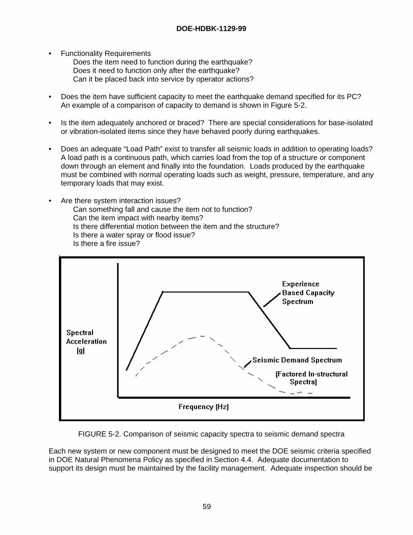
DOE-HDBK-1129-99
59
• Functionality RequirementsDoes the item need to function during the earthquake?Does it need to function only after the earthquake?Can it be placed back into service by operator actions?
• Does the item have sufficient capacity to meet the earthquake demand specified for its PC?An example of a comparison of capacity to demand is shown in Figure 5-2.
• Is the item adequately anchored or braced? There are special considerations for base-isolatedor vibration-isolated items since they have behaved poorly during earthquakes.
• Does an adequate “Load Path” exist to transfer all seismic loads in addition to operating loads?A load path is a continuous path, which carries load from the top of a structure or componentdown through an element and finally into the foundation. Loads produced by the earthquakemust be combined with normal operating loads such as weight, pressure, temperature, and anytemporary loads that may exist.
• Are there system interaction issues?Can something fall and cause the item not to function?Can the item impact with nearby items?Is there differential motion between the item and the structure?Is there a water spray or flood issue?Is there a fire issue?
FIGURE 5-2. Comparison of seismic capacity spectra to seismic demand spectra
Each new system or new component must be designed to meet the DOE seismic criteria specifiedin DOE Natural Phenomena Policy as specified in Section 4.4. Adequate documentation tosupport its design must be maintained by the facility management. Adequate inspection should be
DOE-HDBK-1129-99
60
conducted to make sure the system or component was fabricated and installed as specified in thedesign documents. Documentation must be maintained current throughout the life of the item.
Evaluation of existing systems or components must be conducted based on the “Actual” conditionof the item. This may be different than the design or “As-Built” condition due to field modificationsor deterioration of the item during its service. An examination of the item, its installation, andcurrent condition should be made during a walkdown by seismic engineers as defined in the SEP.Existing systems and components may also be evaluated by use of experience data. This is analternative approach that can be used if the systems or components are installed in an acceptablemanner and meet the rules specified in the SEP to ensure that the item is similar to items in theexperience database. DOE has developed resources for the evaluation of existing systems andcomponents, has conducted training on their application, and has been implementing thedevelopment of seismic evaluation guidelines for systems and components at DOE facilities.
5.8 Fire Scenarios
There have been recent investigations that point to the conclusion that fire scenarios are thedominant risk at most tritium facilities. These fire scenarios are not restricted to seismic-inducedfires, but include fires from all sources. These recent analyses show that the slower burning firesare limiting, and that in almost all cases, these fires result in oxidation rates that are high (inexcess of 90%). Additionally, compliance with National Fire Protection Association (NFPA)requirements, while limiting the potential for fire spread, does not ensure that a full-facility firescenario need not be analyzed. Reference [26] describes the latest findings in this area.
It is possible that fires of sufficient magnitude and frequency exist at some tritium facilities so as towarrant safety system classifications of both the fire suppression and fire detection systems. It haslong been the position of EH-3 that tritium fire suppression and detection systems should beclassified as safety systems (at a minimum as safety-significant, and in some cases as safety-class (e.g., where other safety-class equipment operation is contingent upon fire system operationor where fire scenarios result in unacceptable public dose)), unless documented analyses such asthe FHA or the SAR justify non-classification. This importance that EH-3 places on fire protectionat tritium facilities was highlighted as early as September 1991 during a review of the then-under-construction RTF. The exemption request from some requirements of DOE Orders 5480.7 and6430.1A for RTF were not approved by EH/NS until physical modifications were made to the tritiumfacility. [27]. The definition of tritium that was Material at Risk in selected fire (and seismic)scenarios was also developed prior to startup at RTF, which eventually led to decisions onupgraded selected storage containers and inventory limits. [28]
5.9 Instrumentation
This section provides information on several instruments used to detect and monitor tritium. Thereferences are provided for information only. DOE does not certify that a particular product issuperior to any other product from another vendor. References in this Handbook do not implyendorsement by DOE.
5.9.1 Tritium Monitoring Systems
Several different types of instruments may be used to detect and measure tritium in the operationof a facility. Examples and a discussion of such instrumentation follow:
DOE-HDBK-1129-99
61
• Ionization Chambers — Tritium decays to 3He by the ejection of a beta particle. The betaparticle generated by the decay of tritium ionizes the surrounding gas. The number of ionsproduced due to the loss of energy of the beta particle is a function of the type of gas. Asample of gas is collected in the ionization chamber and the ionization current is measured.The resulting chamber ionization current is proportional to the quantity of tritium in the gas.The larger the measuring chamber volume the higher the output current and the easier it is tomeasure. However, as the volume of the chamber increases, the longer it will take to get anaccurate measurement. Modern electronic systems have solved most of the problemsassociated with measuring small ionization currents in small volumes and as a result, thevolume of the ionization chambers has been reduced over the years from 50L down to 1 or 2L.Most tritium measuring instruments have an ionization chamber.
• Proportional Counters — Gas proportional counters are also used to measure the amount oftritium contained in a gas. A sample of the gas to be monitored is mixed with a counting gasand passed through a proportional counter tube where the pulses caused by the decay oftritium are counted. Proportional counter monitors can be used for most gas monitoringapplications and are also available to measure surface contamination.
• Scintillation Crystal Detectors — Scintillation detector systems are used to measure the totalmole percent of tritium in a sample of gas independent of the chemical composition of thetritium in the gas (HT, DT, T2, and CHxTy). A sample of the gas is introduced into ameasurement chamber at low pressure, generally less than a few torr. The chamber containsa scintillation crystal, which is exposed to the tritium as it decays. The light pulse produced inthe scintillation crystal is either counted or is used to produce a current, which is proportional tothe mole percent tritium contained in the gas sample. Crystal scintillation detection is generallyused to measure the mole percent of tritium in gases containing high concentrations of tritium.
• Mass Spectrometer — Magnetic sector, quadrupole, and drift tube mass spectrometers areused as analytical tools to measure the individual components that make up the gas beingmeasured. Mass spectrometers are generally used for the purposes of assay andaccountability or for scientific purposes. A sample of the gas to be measured is introduced atlow pressure (a few microns) into a chamber and ionized. The ions produced are thenmeasured by a means that discriminates on mass. The number of ions produced at each massis measured and is proportional to the partial pressure of the component in the gas sample.
The sophistication of the measurement systems varies greatly from facility to facility throughout DOE. Light isotope, drift tube, mass spectrometers require a large capital investment andrequire a skilled staff to operate, and, in some cases, may not be cost-effective. All DOEtritium facilities do not require a light isotope drift tube mass spectrometer. Quadrupole massspectrometers and crystal scintillation detectors are much less expensive, but still requireoperation by knowledgeable well-trained personnel. The DOE assay and accountabilityrequirements and regulations do not currently reflect this difference in sophistication and costand currently place the same requirements on small as well as large-scale operations.
• Liquid Scintillation Counters — Due to the need to measure the removable tritium on surfacesand in the body water of workers, almost all tritium facilities are equipped with or have accessto a liquid scintillation counter. If the scintillation counter is not available on site the service cangenerally be purchased from a local firm. Liquid scintillation counters are used to measure thequantity of tritium on surfaces, in liquids, and in dissolved samples. For removable surfacecontamination measurements, a wipe of the surface to be measured is taken using dry paper
DOE-HDBK-1129-99
62
or a Q-Tip. The filter paper or Q-Tip is then placed in a scintillation cocktail, and the quantity oftritium is measured by counting the light flashes that occur in the scintillation cocktail as thetritium decays. The surface contamination is then calculated in units of dpm/100 cm2.
For liquid measurement, a sample of the liquid to be measured is placed in the liquidscintillation cocktail and measured. The tritium concentration of the liquid is calculated inCi/mL. For solid measurement, a known weight of a material is dissolved to produce a liquidand then the liquid is sampled and measured in the scintillation counter. The quantity of tritiumis then calculated in units of Ci/g of the original solid.
• Gas Samplers — Many different types of gas samplers have been developed and used formeasuring very small quantities of tritium in very large volumes of gas. These samplers areused to measure quantities of tritium released through a facility stack and for environmentalmonitoring at a site. Stack exhaust gas monitoring systems generally use an ionizationchamber to measure the tritium in the stack gases and a gas sampler to measure theextremely low levels of tritium that cannot be measured by an ionization chamber.
Most of the stack gas samplers are patterned after the ethylene glycol sampling systemdeveloped at Mound Laboratories. A commercial version of this system is now available. Inthis system, a sample of gas from the stack is circulated through six ethylene glycol bubblers inseries. The first three bubblers remove tritium in the form of HTO, DTO, and T2O. The gasstream is passed through a heated catalytic reactor where tritium in the form of HT, DT, T2, andCHxTy, is cracked and oxidized to form water. This sample is then passed through three moreethylene glycol bubblers to remove the tritium gas, which is now in the form of water. After aperiod from a few hours to days, a sample of the ethylene glycol from each bubbler is removedand counted using a scintillation counter to determine the quantity of tritium in each bubbler.Tritium recovered from the first three bubblers is proportional to the tritium in liquid formcontained in the stack gases and the tritium recovered in the last three bubblers is proportionalto the quantity of tritium in gaseous form contained in the exhaust gases.
Due to the extremely small quantity of tritium contained in the atmospheric gases surrounding atritium facility, the environmental gas samplers use higher flow rate sampler systems thanthose required for stack monitoring, and, in general, collect the water on molecular sieve traps.The water collected on the molecular sieve traps is then recovered from the trap and the tritiumconcentration of the gas passing through the trap is calculated from the tritium concentration ofthe collected water, the gas flow rate through the trap, and the sampling time.
• Portable Room Air Monitors — There are several hand held portable room air monitors on themarket and their capabilities and ranges vary as a function of the different manufacturer andthe purpose for which they were designed. It is convenient in some activities to have thecapability to connect a small hose to the monitor so that it may be used to detect tritium leaksaround equipment.
• Fixed Station Room Air Monitors — Fixed station monitors are designed to be installed in fixedlocations and to be used to monitor the room air tritium concentrations. Depending upon themanufacturer they may have several ranges and are equipped with one or two alarm set pointsand audible as well as visual alarms.
DOE-HDBK-1129-99
63
• Glovebox Atmosphere Monitors — Glovebox monitors may be open mesh or closed ionizationchambers and are designed to monitor the higher levels of tritium inside the gloveboxcontainment systems.
• Hood and Exhaust Duct, Air Monitors — Hood and exhaust duct air monitors are similar tofixed station monitors in range and characteristics.
• Exhaust Stacks, Air Monitors — Exhaust stack monitors are similar to fixed station air monitorsexcept that they generally have larger ionization chambers to increase the sensitivity of themonitor.
• Personnel Friskers and Breath Analyzers — There has been some interest in instrumentswhich can be used to frisk personnel as they enter and exit tritium contaminated areas. OneDOE facility implemented a process of personnel frisking consisting of the use of skin surfacewipes counted in a liquid scintillation counter upon entry and exit from tritium contaminatedareas. In another facility, a hand station based on counting the associated gas flow across thehands was used. To date, the development work required to relate measurements made bythese techniques to dose or worker exposure has not been completed. It is expected thatdifferences in the body chemistry of personnel and differences in the time delay between tritiumexposure and equilibration of tritium in the body will continue to make the results of skinsurface contamination measurement and breath analysis monitoring inconsistent. The impactof false alarms and inconsistent results on worker confidence will probably continue to makethese systems unsatisfactory for worker monitoring.
5.9.2 Specialized InstrumentationThere are many other types of specialized devices and/or instrumentation vendors, and some maybe superior to those discussed here. No endorsement of these devices should be inferred by thereader. A more expansive discussion is planned for the next revision of this Handbook.
5.9.2.a Remote Field Tritium Analysis SystemA prototype system for the remote, in situ analysis of tritium in surface and ground waters hasbeen developed at SRS. Using automated liquid scintillation counting techniques, the FieldDeployable Tritium Analysis System (FDTAS) has been shown in laboratory and field tests to havesufficient sensitivity to measure tritium in water samples at environmental levels (10 becquerels(Bq)/L [~270 pCi/L] for a 100-minute count) on a near-real-time basis.
The prototype FDTAS consists of several major components: a muti-port, fixed volume sampler, anon-line water purification system using single-use “tritium columns,” a tritium detector employingliquid scintillation counting techniques, and the serial communications devices. The sampling andwater purification system, referred to as the “autosampler,” is controlled by a Programmed LogicController pre-programmed to perform a well-defined sampling, purification, and flushing protocol.The tritium analyzer contains custom software in the local computer for controlling the mixing of thepurified sample with liquid scintillation cocktail, counting, and flushing the cell. An externalstandard is used to verify system performance and for quench correction. All operations areinitiated and monitored at the remote computer through standard telephone line modemcommunications. [29]
DOE-HDBK-1129-99
64
5.9.2.b Surface Activity Monitor
A new surface activity monitor (SAM) for measuring tritium on metal (electrically conducting) andnon-metal (electrically non-conducting) surfaces has been recently developed at Ontario HydroTechnologies. [30-32]
The monitor detects tritium on the surface and in the near-surface regions by virtue of primaryionization in air due to the outward electron flux from the contaminated surface. The resulting ionpairs are measured by imposing an electric field between the contaminated surface and a collectorplate. A simple theoretical model relates the total tritium concentration on a surface to themeasured current.
Experiments benchmarking the application of the surface activity monitor on metal surfacesagainst independent measurement techniques of aqueous dissolution and thermal desorptionshow equivalence in the total tritium activities measured. Comparison of surface activity monitormeasurements with the dry polystyrene smear protocol has shown that the two methods arecomplementary. Smearing measures the activity removed by the smear action, which can be usedto infer the total activity on the surface. Surface activity monitor measurements determine the totalactivity on the surface, which can be used to infer removable activity. Ontario Hydro has statedthat this device is the only surface monitor for tritium that provides an absolute measurement of thetotal activity on metallic surfaces.
Experiments demonstrating the application of the surface activity monitor on a variety of non-conducting surfaces have been conducted. Some of the non-conducting surfaces examinedinclude paper, concrete, granite, and wood. Experiments are underway to extend the database ofnon-conducting materials measured by SAM and catalogue the associated collection efficiencies.
Currently, the SAM is commercially available in two models, QP100 and QP200, which havemeasurement ranges of 0 - 200 nCi/cm2 and 0 - 200 µCi/cm2, respectively. A summary of thetechnical specifications of the instrument is given in Table 5-2.
5.9.3.c Breathalyzer
A device undergoing development in Canada is the Scintrex Tritium-In-Breath Monitor. It is anautomatic monitor dedicated towards health physics and radiation biology applications. TheTritium-in-Breath Monitor measures levels of exhaled tritium within 5 minutes of sampling, thussaving considerable time and effort in the monitoring process. This rapid assessment has asensitivity level of 5µCi/L-urine equivalent, which may be sufficient for alarming the cautionarylevels of in-body tritium. Preliminary development of this equipment has been done at the AtomicEnergy of Canada Ltd. research laboratory in Chalk River, Canada.
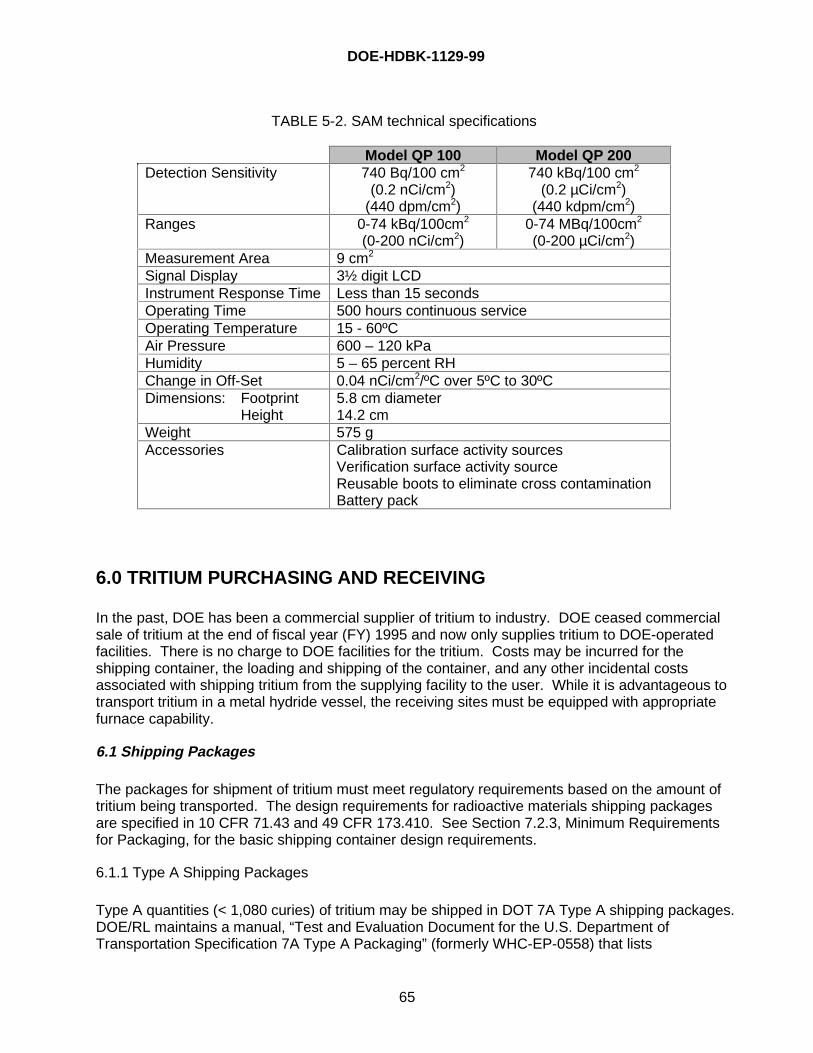
DOE-HDBK-1129-99
65
TABLE 5-2. SAM technical specifications
Model QP 100 Model QP 200Detection Sensitivity 740 Bq/100 cm2
(0.2 nCi/cm2)(440 dpm/cm2)
740 kBq/100 cm2
(0.2 µCi/cm2)(440 kdpm/cm2)
Ranges 0-74 kBq/100cm2
(0-200 nCi/cm2)0-74 MBq/100cm2
(0-200 µCi/cm2)Measurement Area 9 cm2
Signal Display 3½ digit LCDInstrument Response Time Less than 15 secondsOperating Time 500 hours continuous serviceOperating Temperature 15 - 60ºCAir Pressure 600 – 120 kPaHumidity 5 – 65 percent RHChange in Off-Set 0.04 nCi/cm2/ºC over 5ºC to 30ºCDimensions: Footprint
Height5.8 cm diameter14.2 cm
Weight 575 gAccessories Calibration surface activity sources
Verification surface activity sourceReusable boots to eliminate cross contaminationBattery pack
6.0 TRITIUM PURCHASING AND RECEIVING
In the past, DOE has been a commercial supplier of tritium to industry. DOE ceased commercialsale of tritium at the end of fiscal year (FY) 1995 and now only supplies tritium to DOE-operatedfacilities. There is no charge to DOE facilities for the tritium. Costs may be incurred for theshipping container, the loading and shipping of the container, and any other incidental costsassociated with shipping tritium from the supplying facility to the user. While it is advantageous totransport tritium in a metal hydride vessel, the receiving sites must be equipped with appropriatefurnace capability.
6.1 Shipping Packages
The packages for shipment of tritium must meet regulatory requirements based on the amount oftritium being transported. The design requirements for radioactive materials shipping packagesare specified in 10 CFR 71.43 and 49 CFR 173.410. See Section 7.2.3, Minimum Requirementsfor Packaging, for the basic shipping container design requirements.
6.1.1 Type A Shipping Packages
Type A quantities (< 1,080 curies) of tritium may be shipped in DOT 7A Type A shipping packages.DOE/RL maintains a manual, “Test and Evaluation Document for the U.S. Department ofTransportation Specification 7A Type A Packaging” (formerly WHC-EP-0558) that lists

DOE-HDBK-1129-99
66
approximately 15 packages that meet 49 CFR 178.350 for the transportation of Type A quantitiesof liquid or gases. Additionally, several commercial manufacturers will design packages that meetthese radioactive materials shipping criteria.
6.1.2 Type B Shipping Packages
Tritium in Type B quantities (> 1,080 curies) is shipped in the form of uranium tritide in the WSRC-developed Hydride Transport Vessel (HTV). If the tritium is in gaseous form, it is shipped in theWSRC-developed Product Vessel (PV). LP50 containers are no longer used. The HTV and PVcan be packaged for shipment in the Type B, UC-609 shipping package. Primary containers otherthan the HTV and PV can also be shipped in the UC-609. However, if tritium is ordered from or isto be returned to a DOE facility, it is generally shipped in an HTV or PV if packaged inside the UC-609. For design and analysis purposes, the storage vessel receives no credit for tritiumcontainment. The package can be transported as non-exclusive (i.e., with other than radioactivecargo) use by highway, rail, water, or air.
Type B quantities may also be transported from one DOE site to another in the Sandia-designedH1616 shipping package. DOE authorization is required before using the H1616 package. Theprimary tritium container enclosed inside the H1616 must meet the Sandia National Laboratory(SNL) specification SS393217. The HTV is qualified for shipment in the H1616 packaging andmeets the SNL specification [33]. Of the two H1616 variations, H1616-1 and H1616-2,qualification for transport in the H1616-1 automatically includes qualification for transport in theH1616-2. The next revision to this handbook is planned to include relevant information on theH1616 design, operational procedures, packaging and shipping requirements, and limitations onuse.
Caution should be exercised when shipping “empty” HTVs, as the residual heel may contain> 1080 curies, thereby requiring a Type B shipment for the “empty” HTV.
6.2 Product Containers
6.2.1 WSRC, Product Vessel
The WSRC PV is designed for use with the UC-609 to ship up to 10 grams of gaseous tritium in asingle valve, 21L-volume container at pressures up to 1,200 torr. The PV is designed to meet therequirements of the ASME Boiler and Pressure Vessel Code, Section VIII, Division 1, 1991Addenda, Lethal Service, Full Vacuum to 8.5 psig (1,200 torr) at 77oF.
Although the PV is designed to meet ASME code requirements, the PV is not ASME codestamped. The vessel is equipped with a single valve, Nupro SS-4HS-TW valve, 316 SS bodyand is closed with a male Cajon SS-4-VCR-4 nut and a Cajon SS-4-VCR-CP cap.
6.2.2 WSRC, Hydride Transport Vessel
The HTV [33] can be loaded with a maximum of 3 moles (18 grams) of tritium as uranium tritide.The main body of the HTV is fabricated from two four-inch Schedule 40 pipe caps, welded togetherand contains a free volume of approximately 690 cubic centimeters. The HTV weighs 9.3 pounds,has a maximum outside diameter of 4.560 inches, and is 9.980 inches high. The HTV is equippedwith two ports with a single Nupro SS-4HS-TW closure valve on each port. Both ports areequipped with 2-micron nominal pore size, cup shaped, porous stainless steel filters welded on the
DOE-HDBK-1129-99
67
end of the port tube inside the vessel. The purpose of the filters is to confine the uranium powder.One filter is positioned in the volume above the uranium and is connected through a valve to thefemale port with a Cajon SS-4-VCR-1 female nut. The second filter, connected through the valveto the male port, is positioned below the level of the uranium powder in the bottom of the vesseland is connected through the valve to the male port with a Cajon SS-4-VCR-4 male nut. Bothports are used when the bed is used in a flow-through mode of operation.
The maximum normal unloading temperature is 450oC, and the maximum unloading pressure attemperature is 2.9 psia. Exceeding the 2.9 psia pressure at temperature will impact the vesselservice life.
When uranium is loaded to full stoichiometry with tritium to form UT3, it retains the decay helium inthe solid for about 300 days until the concentration of helium reaches approximately 0.134 He/U,after which, some of the helium will be released from the solid. The helium release rate increasesover a period of about 600 days, until it equalizes with the helium generation rate.
The HTV Dissociation Pressure [33], P is
log Patm = -(4038.2/T) + 6.074
where T = temperature (K)
which impliesPatm = 10 -(4038.2/T) + 6.074
The second equation for the HTV Dissociation Pressure is
log P psia = -(4038.2/T) + 7.2413
which implies
Ppsia = 10 -(4038.2/T) + 7.2413
WSRC conducted several tests on the HTV to determine the impact of an air ingress incident. Theresults indicate that in the dehydride state, the uranium reacted with both oxygen and nitrogen inthe air. The reaction stopped when the accumulation of argon and moisture in the vessel reachedatmospheric pressure and prevented additional air from entering the vessel. The maximumtemperature was approximately 200oC. If air is drawn through the uranium continuously, atemperature higher than 1,000oC can be reached, and damage to the vessel may occur. There aresome current issues associated with HTV qualification and use that are being addressed at SRS,the results of which will be included in the next revision to this document.
6.2.3 Recommendations for Improvements for Product Containers
Both the PV and HTV containers are single-valve designs (although the HTV actually has twovalves; one for filling and one for evacuating), employing an SS-4HS-TW valve. Selection of thisvalve was based in part on the favorable rating it received against valves of similar size. It is ratedat 315°C and 1000 psig. Additionally, the valve stem tip is Stellite™ spherical design, a desirabletip configuration. Although the leak rate is verified annually at SRS, the employment of a single H-type valve close to the heat zone is not an optimal design, as described in EH Technical Notice 94-
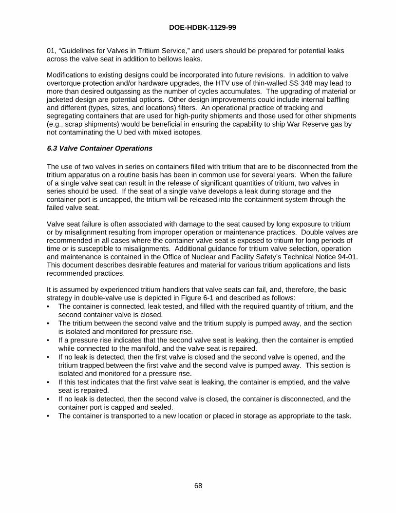
DOE-HDBK-1129-99
68
01, “Guidelines for Valves in Tritium Service,” and users should be prepared for potential leaksacross the valve seat in addition to bellows leaks.
Modifications to existing designs could be incorporated into future revisions. In addition to valveovertorque protection and/or hardware upgrades, the HTV use of thin-walled SS 348 may lead tomore than desired outgassing as the number of cycles accumulates. The upgrading of material orjacketed design are potential options. Other design improvements could include internal bafflingand different (types, sizes, and locations) filters. An operational practice of tracking andsegregating containers that are used for high-purity shipments and those used for other shipments(e.g., scrap shipments) would be beneficial in ensuring the capability to ship War Reserve gas bynot contaminating the U bed with mixed isotopes.
6.3 Valve Container Operations
The use of two valves in series on containers filled with tritium that are to be disconnected from thetritium apparatus on a routine basis has been in common use for several years. When the failureof a single valve seat can result in the release of significant quantities of tritium, two valves inseries should be used. If the seat of a single valve develops a leak during storage and thecontainer port is uncapped, the tritium will be released into the containment system through thefailed valve seat.
Valve seat failure is often associated with damage to the seat caused by long exposure to tritiumor by misalignment resulting from improper operation or maintenance practices. Double valves arerecommended in all cases where the container valve seat is exposed to tritium for long periods oftime or is susceptible to misalignments. Additional guidance for tritium valve selection, operationand maintenance is contained in the Office of Nuclear and Facility Safety’s Technical Notice 94-01.This document describes desirable features and material for various tritium applications and listsrecommended practices.
It is assumed by experienced tritium handlers that valve seats can fail, and, therefore, the basicstrategy in double-valve use is depicted in Figure 6-1 and described as follows:• The container is connected, leak tested, and filled with the required quantity of tritium, and the
second container valve is closed.• The tritium between the second valve and the tritium supply is pumped away, and the section
is isolated and monitored for pressure rise.• If a pressure rise indicates that the second valve seat is leaking, then the container is emptied
while connected to the manifold, and the valve seat is repaired.• If no leak is detected, then the first valve is closed and the second valve is opened, and the
tritium trapped between the first valve and the second valve is pumped away. This section isisolated and monitored for a pressure rise.
• If this test indicates that the first valve seat is leaking, the container is emptied, and the valveseat is repaired.
• If no leak is detected, then the second valve is closed, the container is disconnected, and thecontainer port is capped and sealed.
• The container is transported to a new location or placed in storage as appropriate to the task.
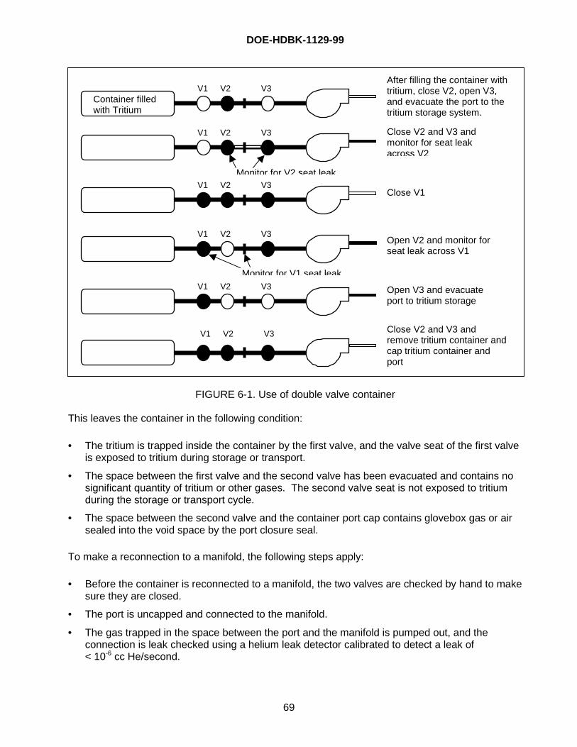
DOE-HDBK-1129-99
69
FIGURE 6-1. Use of double valve container
This leaves the container in the following condition:
• The tritium is trapped inside the container by the first valve, and the valve seat of the first valveis exposed to tritium during storage or transport.
• The space between the first valve and the second valve has been evacuated and contains nosignificant quantity of tritium or other gases. The second valve seat is not exposed to tritiumduring the storage or transport cycle.
• The space between the second valve and the container port cap contains glovebox gas or airsealed into the void space by the port closure seal.
To make a reconnection to a manifold, the following steps apply:
• Before the container is reconnected to a manifold, the two valves are checked by hand to makesure they are closed.
• The port is uncapped and connected to the manifold.
• The gas trapped in the space between the port and the manifold is pumped out, and theconnection is leak checked using a helium leak detector calibrated to detect a leak of< 10-6 cc He/second.
After filling the container withtritium, close V2, open V3,and evacuate the port to thetritium storage system.
Close V2 and V3 andmonitor for seat leakacross V2
V1 V2 V3
Monitor for V2 seat leak
Close V1
Close V2 and V3 andremove tritium container andcap tritium container andport
Open V2 and monitor forseat leak across V1
Open V3 and evacuateport to tritium storage
V1 V2 V3
Monitor for V1 seat leakV1 V2 V3
Container filledwith Tritium
V1 V2 V3
V1 V2 V3
V1 V2 V3
DOE-HDBK-1129-99
70
• If the port connection is leaking, the leak is repaired, and the leak test is rerun.
• The first hand valve is opened and then closed to allow tritium from the container to enter thevoid space between the two valves.
• The second hand valve is opened and then closed to allow the trapped tritium to expand intothe port volume.
• The outside of the port connection area can be sniffed with a tritium monitor. The containmentsystem tritium monitor may be observed for an increase in tritium concentration to detect atritium leak from the port connection into the containment volume.
• If no leak is detected, then the two series valves may be opened, and the reconnection iscomplete.
6.3.1 Tritium Apparatus, Isolation Valves, and Purge Ports
A “purge port” is a capped, sealed port connected through a valve to a potentially tritium-contaminated volume. The purpose of a purge port is to provide a path, which can be used toremove tritium-contaminated gases from the isolation volume prior to making a line break at thecomponent flanges to remove a component. If the tritium-contaminated gases are not removedfrom the isolation volume, they will be released into the containment system when the flange isunsealed. The released gases and outgassing from the isolation volume surfaces will contaminatethe containment volume gases. Following removal and replacement of a component, the port isused to leak test the new component and flange seals prior to placing the component in service.
Figure 6-2 is an illustration of two purge ports installed to allow evacuation of the volume and leaktesting of the flanges between two sets of valves, thus allowing isolation and removal of a tritium-contaminated component. Note that the purge ports are part of the permanently installed system,and are not part of the component.
FIGURE 6-2. Purge ports and isolation valves
Isolation Valves Component to be removed/repaired
Isolation Valves Connected to the rest of the T2 system
Evacuate port volume; check for leaks
Purge Ports
Component to be removed/repaired
Evacuate isolation valve volume
Component flanges
Component to be removed/repaired
Backfill with air; repeat evacuate backfill cycle as necessary
Purge with air
Air purge valve
DOE-HDBK-1129-99
71
The component is isolated with two valves on each side of the component, and a purge port hasbeen installed between each set of valves. The purge port allows evacuation of the volumebetween the two valves to remove the tritium-contaminated gases from the isolation volume priorto removal of the component.
In operation, the two sets of valves are closed to isolate the component from the rest of the tritiummanifold. A vacuum pump is connected to the two purge ports. The purge port valves are openedand the gases trapped between the isolation valves are evacuated to remove the tritium-contaminated gases. In most applications, air is allowed to enter the purged volume, and theevacuation operation is repeated. Other gases, such as argon and nitrogen, may be used;however, air is usually more effective at decontaminating the surfaces. Ambient air entering thepurged volume contains several thousand parts per million of normal water along with the nitrogenand oxygen. Some of the tritium and HTO on the internal surfaces of the purged volume exchangewith the hydrogen and water in the ambient air and are pumped out during the purge cycle. Thispurge/backfill cycle is repeated 3 to 6 times to remove as much of the tritium as possible beforedisconnecting the component. Performance of three ambient air purge backfill cycles is typical,and, in practice, more than 6 purge backfill cycles has not proven to be beneficial.
After the component has been removed and replaced, the new component is leak tested thoroughthe purge port before the isolation valves are opened. The sequence of operations is as follows:
• The four component isolation valves are closed.• The purge ports are uncapped and connected to a vacuum pumping system.• The port volume is evacuated and leak checked.• If no leaks are found, the purge port valves are opened, and the gases in the volume between
the isolation valves are evacuated to a tritium-contaminated waste gas collection and removalsystem.
• The evacuation valve is closed, and air is allowed to enter the isolation volume through a valvemounted on the maintenance manifold.
• The air inlet valve is closed. The ambient air is allowed to sit in the isolation volume for a fewminutes to allow the exchange of hydrogen and tritium to take place.
• The evacuation valve is opened, and the volume is again pumped out to the cleanup system.• This evacuation and/or backfill sequence can be repeated several times.• The component is disconnected at the maintenance flanges and removed. The new
component is installed.• To control outgassing from the removed component, blind flanges with installed purge ports
may be installed over the open end of the removed component.• The new flange connections are leak tested through the purge ports. If the new flange
connections are not leak tight, they are repaired or replaced and retested.• When the component and flanges are leak tight, the purge valves are closed, disconnected
from the leak test system, and capped.• The component isolation valves are opened, and the new component is placed in service.
As is always the case when dealing with process quantities of tritium, adherence to procedures isparticularly important. If a large source (e.g., container) of tritium is connected via valving to thepiping used in evacuating, an inadvertent valve operation could result in a significant loss. Onesuch incident occurred at Mound, in which a valve was inadvertently opened, resulting in a loss ofapproximately 10 grams of tritium to the cleanup system via the evacuation header.
DOE-HDBK-1129-99
72
6.4 Receiving Tritium
Nuclear Material may be delivered to a receiving area, a receiving storage area, or directly to thetritium-handling facility. A brief description of the DOE regulatory requirement is as follows:
• The Receiving Area and/or Receiving Storage Area must be inside a posted “Controlled Area.”• The Receiving Area and/or Receiving Storage Area must be inside a posted “Radioactive
Materials Area (RMA).”• The Receiving Area and/or Receiving Storage Area must be posted to reflect the radiological
hazard that exists due to the quantity and types of nuclear material received and/or stored.• The Receiving Area and/or Receiving Storage Area must be inside a “Controlled Area” and
posted as a Controlled Area.• Inside the Controlled Area is an area posted as a RMA.• The boundary of the Controlled Area and the RMA can be the same boundary.
The area where the nuclear material is being kept while waiting to be transported from theReceiving Area must be posted as a Controlled Area and an RMA while the nuclear material ispresent. When the nuclear material is moved to a Storage Area, the signs can be removed. Whilein the Receiving Area and/or Storage Area, the material must remain in the certified shippingcontainer. No nuclear material handling or unpacking can take place in this area.
As long as the material remains packaged in the approved container (includes certification), thequantities are not a facility issue during the receiving process. However, the total site quantities,including the packaged material, cannot exceed limits specified in the site’s EIS.
Site and facility management may have internal requirements and limits associated with the receiptand storage of nuclear materials. In general, as long as the material remains in the approvedshipping package it can be received, stored, and transported per requirements.
The container should be radiologically surveyed to determine radiological posting needs and toensure it is safe for storage. When the material is removed from the receiving area, the RMA, andControlled Area, and radiological sign may be removed.
6.5 Storage of Packaged Nuclear Materials
The packaged nuclear materials may be transported to a storage area while awaiting transport to atritium-handling operations area. While in the Storage Area the same rules apply as those in theReceiving Area.
• The Storage Area must be inside a posted “Controlled Area.”• The Storage Area must be inside a posted “RMA.”• The Storage Area must be posted to reflect the radiological hazard that exists due to the
quantity and types of nuclear material stored.• The nuclear material must remain packaged in the certified shipping containers.• Periodic surveys must be performed and be sufficiently detailed to determine that surface
contamination levels are not exceeded, airborne releases are not occurring, and packages arenot leaking.
DOE-HDBK-1129-99
73
7.0 PACKAGING AND TRANSPORTATION
7.1 General Administrative Packaging and Transport Requirements
Transport of tritium in concentrations greater than 70 Bq/g (0.002 •Ci/g) meets the definition of aClass 7 (Radioactive) Material under DOT regulations. As a hazardous material, tritium is subjectto the DOT hazardous materials regulations (HMR) in 49 CFR Parts 106 through 180. Theseregulations specify the shipping paper, marking, labeling, placarding, and packaging requirementsfor hazardous material. The safety requirements for packaging are dependent on the type, form,and quantity of tritium, per DOE O 460.1A, “Packaging and Transportation Safety”. Additionalpackaging and transportation regulations for radioactive material, established by the U.S. NuclearRegulatory Commission (NRC), are found in 10 CFR 71.
Tritium may also meet the definition of other hazard classes in 49 CFR 173; e.g., tritium gas, incertain conditions, may meet the definition of a flammable gas. Tritium-contaminated hazardouswaste will be subject to the requirements for hazardous waste shipments.
Organizational responsibility for the packaging and transport of hazardous materials such as tritiumneed to be clearly defined. Written procedures must be developed for the operations that packageand ship tritium. DOT hazardous materials regulations (49 CFR 172.704) require initial andrecurrent general awareness/familiarization, safety-related and function-specific training forhazardous materials workers.
There are also pre-transport requirements applicable to hazardous/mixed wastes that addresspackaging, labeling, marking, placarding, and accumulation time provisions which can be found in40 CFR 262.30 – 34.
The guidance provided in this Handbook assumes that tritium is the only radioactive material in thepackages. If another radionuclide is present, additional requirements may apply to the packagingand transport of the combination of radioactive materials.
7.2 Selection of Proper Packaging
The package types for radioactive material are limited quantity excepted package, low specificactivity (LSA), surface contaminated object (SCO), Type A and Type B. The definitions of thepackage types are listed in order of increasing allowable radioactivity material limits.
• Limited Quantity Excepted Package: The requirements for a limited quantity package of tritiumare as follows:
— The radiation level at any point on the external surface of the package does not exceed0.005 milliSievert (mSv)/hr (0.5 mrem/hr).
— The amount of radioactive material is less than the limit in 49 CFR 173.425 (see Table 7-1).— The package meets the general design requirements for radioactive materials packaging
from 49 CFR 173.410 (see Section 7.2.3).— The nonfixed (removable) contamination on the external surface of the package does not
exceed the limits in 49 CFR 173.443 (0.41 Bq/cm2 or 22 dpm/cm2 for tritium).— The outside of the inner or outer packaging is marked “Radioactive.”
DOE-HDBK-1129-99
74
The advantage to using the limited quantity excepted packaging is that it is excepted fromspecification packaging, marking, labeling, and, if not a hazardous substance or hazardouswaste, it is also excepted from the shipping paper and certification requirements of the HMR.
• LSA is a quantity of Class 7 (radioactive) material with limited specific activity. Shieldingmaterials surrounding the LSA material may not be considered in determining the estimatedaverage specific activity of the package contents. The definition for LSA was recently revisedinto three groups: LSA-I, LSA-II, and LSA-III. Type A packages, which are discussed later, arelimited to an A2 quantity of radioactivity where the quantity A2 is listed in the regulatorydocumentation for each individual radioactive material. The A2 quantity for tritium is 40 TBq(1080 Ci) per Type A package. The LSA activity limits are based on the Type A package A2
quantity limit. The definitions for these groups are provided below.
— LSA-I is defined as contaminated earth, concrete, rubble, other debris, and activatedmaterial in which the radioactive material is essentially uniformly distributed and theaverage specific activity does not exceed 10-6A2/g. For tritium, the maximum allowablespecific activity for LSA-I is 4 x 10⁻⁵ TBq/g (0.001 Ci/g, 1 Ci/kg, or 2.2 lb/Ci).
— LSA-II is defined as either water with tritium concentration up to 0.8 TBq/L (20.0 Ci/L) ormaterial in which Class 7 (radioactive) material is essentially uniformly distributed and theaverage specific activity does not exceed 10-4A2/g for solids and gases and 10-5A2/g forliquids. For tritium-contaminated solids or gases, the maximum allowable specific activity is0.004 TBq/g (0.1 Ci/g, 100 Ci/kg). The resulting limit for tritium-contaminated liquid (otherthan tritiated water) is 4 x 10⁻⁴ TBq/g (0.01 Ci/g).
— LSA-III is defined as solids such as consolidated wastes or activated materials that meetthe testing requirements of 49 CFR 173.468 (water leach test) and the followingrequirements:
� The Class 7 (radioactive) material is essentially uniformly distributed throughout a solidor a collection of solid objects or essentially uniformly distributed in a solid compactbinding agent (such as concrete, bitumen, or ceramic).
� The Class 7 (radioactive) material is relatively insoluble, or is intrinsically contained in arelatively insoluble material, so that, even under loss of packaging, the loss of Class 7(radioactive) material per package by leaching when placed in water for seven dayswould not exceed 0.1 A2. The resulting limit for tritium is 4 TBq (108 Ci).
� The average specific activity of the solid does not exceed 2 x 10⁻³A2/g. The resultinglimit for tritium is 0.08 TBq/g (2.16 Ci/g).
The advantage to using LSA instead of Type A packaging is that, for exclusive use shipments, bulkand strong, tight packaging can be used in some cases, if authorized. In addition, LSA packagesare excepted from the marking and labeling requirements of 49 CFR 173 Subpart I.
• SCO is similar to LSA but is limited to a solid object that is not itself radioactive but has Class 7(radioactive) material distributed on any of its surfaces. SCO is divided into two groups, SCO-Iand SCO-II. The definitions are provided below.
— SCO-I is defined as a solid object that meets all of the following requirements:
� The nonfixed contamination on the accessible surface averaged over 300 cm2 (or thearea of the surface if less than 300 cm2) does not exceed 4 Bq/cm2 (10-4 •Ci/c m2) forbeta emitters such as tritium.
DOE-HDBK-1129-99
75
� The fixed contamination on the accessible surface averaged over 300 cm2 (or the areaof the surface if less than 300 cm2) does not exceed 4 x 10⁴ Bq/cm2 (1 •Ci/cm2) forbeta emitters such as tritium.
� The nonfixed plus the fixed contamination on the inaccessible surface averaged over300 cm2 (or the area of the surface if less than 300 cm2) does not exceed 4 x 10⁴
Bq/cm2 (1 •Ci/cm2) for beta emitters such as tritium.
— SCO-II is defined as a solid object on which the limits for SCO-I are exceeded and meetsall of the following requirements:
� The nonfixed contamination on the accessible surface averaged over 300 cm2 (or thearea of the surface if less than 300 cm2) does not exceed 400 Bq/cm2 (10-2 •Ci/c m2) forbeta emitters such as tritium.
� The fixed contamination on the accessible surface averaged over 300 cm2 (or the areaof the surface if less than 300 cm2) does not exceed 8 x 10⁵ Bq/cm2 (20 •Ci/cm2) forbeta emitters such as tritium.
� The nonfixed plus the fixed contamination on the inaccessible surface averaged over300 cm2 (or the area of the surface if less than 300 cm2) does not exceed 8 x 10⁵
Bq/cm2 (20 •Ci/cm2) for beta emitters such as tritium.
• Type A packages are limited to an A2 quantity of radioactivity. The A2 limit for tritium is 40 TBq(1080 Ci) per package. The physical form of the package contents must be within theenvelope of the contents used during testing of the package. Type A packages aresignificantly less expensive and much easier to obtain than Type B packages.
• Type B packages provide the highest level of safety features of all types of radioactive materialpackaging. The contents are limited by the requirements of the Certificate of Compliance(CoC) for the package. The CoC is issued by the agency that certifies that the package meetsthe Type B requirements.
7.2.1 Form and Quantity of Tritium
The form of the tritium affects the quantity of tritium that may be shipped in one package and thedesign and testing requirements for the packaging. Table 7-1 is a comparison of the allowablequantities of tritium in various package types.
7.2.2 Evaluation of Approved Packaging
Tritium-contaminated solid waste is typically packaged in DOT Type A, Specification 7A open head55-gallon drums or Type A metal boxes. The maximum amount of tritium that may be shipped in aType A package is 40 TBq (1080 curies).
Packages containing over 40 TBq of tritium must meet the Type B container requirements. Thesecontainers are few in number, and, compared to Type A packages, expensive to manufacture anduse. If Type B packages are to be considered for shipments, the CoC should be reviewedcarefully against the form and quantity of tritium to be shipped.
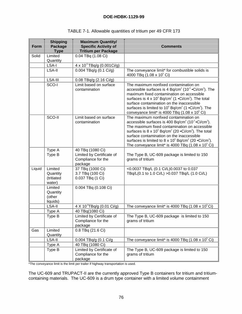
DOE-HDBK-1129-99
76
TABLE 7-1. Allowable quantities of tritium per 49 CFR 173
FormShippingPackage
Type
Maximum Quantity/Specific Activity of
Tritium per PackageComments
Solid LimitedQuantity
0.04 TBq (1.08 Ci)
LSA-I 4 x 10⁻⁵ TBq/g (0.001Ci/g)LSA-II 0.004 TBq/g (0.1 Ci/g) The conveyance limit* for combustible solids is
4000 TBq (1.08 x 10⁵ Ci)LSA-III 0.08 TBq/g (2.16 Ci/g)SCO-I Limit based on surface
contaminationThe maximum nonfixed contamination onaccessible surfaces is 4 Bq/cm2 (10-4 •Ci/cm2). Themaximum fixed contamination on accessiblesurfaces is 4 x 10⁴ Bq/cm2 (1 •Ci/cm2). The totalsurface contamination on the inaccessiblesurfaces is limited to 104 Bq/cm2 (1 •Ci/cm2). Theconveyance limit* is 4000 TBq (1.08 x 10⁵ Ci)
SCO-II Limit based on surfacecontamination
The maximum nonfixed contamination onaccessible surfaces is 400 Bq/cm2 (10-2 •Ci/cm2).The maximum fixed contamination on accessiblesurfaces is 8 x 10⁵ Bq/cm2 (20 •Ci/cm2). The totalsurface contamination on the inaccessiblesurfaces is limited to 8 x 10⁵ Bq/cm2 (20 •Ci/cm2).The conveyance limit* is 4000 TBq (1.08 x 10⁵ Ci)
Type A 40 TBq (1080 Ci)Type B Limited by Certificate of
Compliance for thepackage
The Type B, UC-609 package is limited to 150grams of tritium
Liquid LimitedQuantity(tritiatedwater)
37 TBq (1000 Ci)3.7 TBq (100 Ci)0.037 TBq (1 Ci)
<0.0037 TBq/L (0.1 Ci/L)0.0037 to 0.037TBq/L(0.1 to 1.0 Ci/L) >0.037 TBq/L (1.0 Ci/L)
LimitedQuantity(otherliquids)
0.004 TBq (0.108 Ci)
LSA-II 4 X 10⁻⁴TBq/g (0.01 Ci/g) The conveyance limit* is 4000 TBq (1.08 x 10⁵ Ci)Type A 40 TBq(1080 Ci)Type B Limited by Certificate of
Compliance for thepackage
The Type B, UC-609 package is limited to 150grams of tritium
Gas LimitedQuantity
0.8 TBq (21.6 Ci)
LSA-II 0.004 TBq/g (0.1 Ci/g The conveyance limit* is 4000 TBq (1.08 x 10⁵ Ci)Type A 40 TBq (1080 Ci)Type B Limited by Certificate of
Compliance for thepackage
The Type B, UC-609 package is limited to 150grams of tritium
*The conveyance limit is the limit per trailer if highway transportation is used.
The UC-609 and TRUPACT-II are the currently approved Type B containers for tritium and tritium-containing materials. The UC-609 is a drum type container with a limited volume containment
DOE-HDBK-1129-99
77
vessel. The containment vessel is authorized for containers of tritium gas, tritiated water, ortritium-containing solids and is limited to 150 grams of tritium. The TRUPACT-II is authorized forfourteen DOT Type A, Specification 7A 55-gallon drums or two Standard Waste Boxes. Theauthorized waste forms for the TRUPACT-II are solids or solidified liquids.
Tritium waste that meets the definition of LSA or SCO may be shipped domestically in a DOT TypeA, Specification 7A packaging or a strong, tight package. A strong, tight package is defined as apackage that prevents leakage of the radioactive content under normal conditions of transport. Astrong, tight package may be used if the shipment is made for exclusive use and each package islimited to 40 TBq (1080 Ci) of tritium.
7.2.3 Minimum Requirements for Packaging
The design requirements for a radioactive materials package are located in 10 CFR 71.43 and49 CFR 173.410. These requirements include the following:
• The smallest overall dimension may not be less than 10 centimeters (4 inches).• The outside of the package must incorporate a feature, such as a seal, that is not readily
breakable and that, while intact, would be evidence that the package had not been opened byunauthorized persons.
• A containment system securely closed by positive fastening devices that cannot be openedunintentionally or by a pressure that may arise within the package.
• Materials and construction that ensure that there will be no significant reaction between thepackage components, and contents, including possible reaction resulting from inleakage ofwater, to the maximum credible extent. Account must be taken of the behavior of materialsunder irradiation. (Irradiation of materials is not a significant consideration with tritium.However, chemical compatibility with hydrogen needs to be evaluated for shipments ofgaseous tritium.)
• Any valves or devices, the failure of which would allow radioactive contents to escape, must beprotected against unauthorized operation and, except for a pressure relief device, must beprovided with an enclosure to retain any leakage.
• Design, construction, and preparation for shipment so that under the tests specified in10 CFR 71.71 there would be no loss or dispersal of contents, no significant increase in theexternal surface radiation level, and no substantial reduction in the effectiveness of thepackaging.
• No features that will allow continuous venting.• The package can be easily handled and properly secured in or on a conveyance during
transport.• Each lifting attachment that is a part of the package must be designed with a minimum safety
factor of five, based upon breaking strength, when used to lift the package in the intendedmanner, and it must be designed so that failure of any lifting attachment under excessive loadwould not impair the ability of the package to meet other requirements of 49 CFR Subpart I.Any other structural part of the package, which could be used to lift the package, must becapable of being rendered inoperable for lifting the package during transport or must bedesigned with strength equivalent to that required for lifting attachments.
• The external surfaces, as far as practicable, will be free from protruding features and will beeasily decontaminated.
• The outer layer of packaging will avoid, as far as practicable, pockets or crevices where watermight collect.
• Each feature that is added to the package will not reduce the safety of the package.
DOE-HDBK-1129-99
78
• The package will be capable of withstanding the effects of any acceleration, vibration, orvibration resonance that may arise under normal conditions of transport without anydeterioration in the effectiveness of the closing devices on the various receptacles or in theintegrity of the package as a whole and without releasing the nuts, bolts, or other securingdevices even after repeated use.
For transport by air, the following requirements apply:
• The integrity of containment will not be impaired if the package is exposed to ambienttemperatures ranging from -40°C (-40°F) to 55°C (131°F).
• Packages containing liquids will be capable of withstanding, without leakage, an internalpressure that produces a pressure differential of not less than 95 kPa (13.8 lb./square inch).
The surface temperature of packages is limited to 38°C (100°F) for nonexclusive shipments and50°C (122°F) for exclusive shipments. This requirement should not be an issue with tritiumshipments based on the low decay heat for tritium.
The requirements for Type A packages include the ability to withstand the following tests specifiedin 49 CFR 173.465:
• Water spray–simulation of 2 inches of rainfall per hour for at least one hour.• Free drop–a drop of 1 to 4 feet, depending on the package mass, onto a hard surface.• Stacking–compressive load of five times the package mass for a minimum of 24 hours.• Penetration–this test is performed by dropping a 6 kilogram, 3.2 centimeter steel bar onto the
weakest point of the package from a minimum height of one meter.
Packages designed for liquids and gases are required to pass a more rigorous free drop andpenetration test than solids.
7.2.4 Onsite versus Offsite Shipments
Offsite shipments of hazardous materials or any shipment that meets the requirements of“transportation in commerce” must comply with the HMR. DOT provided a clarification oftransportation in commerce in a 1991 letter to DOE. The following is excerpted from the letter:
“Transportation on (across or along) roads outside of Government propertiesgenerally is transportation in commerce. Transportation on government propertiesrequires close analysis to determine whether it is in commerce. If a road is used bymembers of the general public (including dependents of Government employees)without their having to gain access through a controlled access point, transportationon (across or along) that road is in commerce. On the other hand, if access to aroad is controlled at all times through the use of gates and guards, transportation onthat road is not in commerce.
“One other means of preventing hazardous materials transportation on Governmentproperty from being in commerce is to temporarily block access to the section of theroad being crossed or used for that transportation. The road would have to beblocked by persons having the legal authority to do so and public access to theinvolved section of road would have to be effectively precluded.”
DOE-HDBK-1129-99
79
Attachment 1 to DOE Order 460.2, “Departmental Materials Transportation and PackagingManagement,” requires that contractors shall comply with the HMR for on site materials transfersor comply with an approved site- or facility specific Transportation Safety Document that describesthe methodology and compliance process to meet equivalent safety for any deviation from theHazardous Materials Regulations.
7.3 Package Loading and Preparation for Shipment
7.3.1 Disassembly and Inspection of the Package
DOE Order 460.2 requires that DOE contractors inspect incoming hazardous materials shipmentsfor damage or loss and evidence of leakage. Radioactive material shipments shall be inspectedfor external surface contamination and dose rate.
Preliminary determinations prior to first use of any packaging are required by 10 CFR 71.85. Thedeterminations are as follows:
• Ascertain that there are no cracks, pinholes, uncontrolled voids, or other defects that couldsignificantly reduce the effectiveness of the packaging.
• Where the maximum normal operating pressure will exceed 35 kPa (5 lb/in2) gauge, thepackage user shall test the containment system at an internal pressure at least 50 percenthigher than the maximum normal operating pressure to verify the capability of that system tomaintain its structural integrity at that pressure.
Prior to the first use of any radioactive materials packaging, 49 CFR 173.474 requires the offerer todetermine the following:
• The packaging meets the quality of design and construction requirements as specified in49 CFR Subpart I.
• The effectiveness of the shielding, containment, and, when required, the heat transfercharacteristics of the package, are within the limits specified for the package design.
7.3.2 Package Loading and Assembly Operations
Sections 10 CFR 71.87 and 49 CFR 173.475 require routine determinations during the loading of aradioactive materials package. Before each shipment of any Class 7 (radioactive) material, theofferer must ensure, by examination or appropriate tests, the following:
• The packaging is proper for the contents to be shipped.• The packaging is in unimpaired physical condition, except for superficial marks.• Each closure device of the packaging, including any required gasket, is properly installed,
secured, and free of defects.• Each special instruction for filling, closing, and preparation of the packaging for shipment has
been followed.• Each closure, valve, or other opening of the containment system through which radioactive
material might escape is properly closed and sealed.• The internal pressure of the containment system will not exceed the design pressure during
transportation.• External radiation and contamination levels are within the allowable limits specified in
49 CFR 173 Subpart I.
DOE-HDBK-1129-99
80
• Any system for containing liquid is adequately sealed and has adequate space or otherspecified provision for expansion of the liquid.
• Any pressure relief device is operable and set in accordance with written procedures.• Any structural part of the package that could be used to lift or tie down the package during
transport is rendered inoperable for that purpose, unless it satisfies the design requirements of10 CFR 71.45. (See Section 7.2.3.)
• Accessible package surface temperatures will not exceed the limits in 10 CFR 71.43 at anytime during transportation. (See Section 7.2.3.)
7.3.3 Leak Testing
Leak testing is required for radioactive materials shipments in Type B packages to ensure that thetritium is contained within the package. The package must be leak-tight as defined by AmericanNational Standards Institute (ANSI) N14.5. Assembly verification and maintenance verificationleak testing requirements will be noted in the CoC for the Type B package.
Packages that contain liquid in excess of the A2 quantity for tritium (40 TBq or 1,080 Ci) andintended for air shipment must be tested to show that they will not leak under an ambientatmospheric pressure of not more than 25 kPa, absolute (3.6 psia). The test must be conducted todetermine compliance with this requirement on the entire containment system or on any receptacleor vessel within the containment system.
7.3.4 Preparation for Shipment
For each shipment of more than 40TBq (1080 Ci) of radioactive material, DOE Order 460.2requires the contractor to notify the shipment consignee of the dates of the shipment, the expecteddate of arrival, and any special loading or unloading instructions. Placarding for tritium shipmentsis required if the packages are labeled with Radioactive Yellow III labels or for exclusive useshipments. Marking, labeling, and shipping paper requirements from 49 CFR 172 need to beevaluated for each shipment of hazardous materials.
7.4 Documentation and Records
The 10 CFR 71.1 record may be the original or a reproduced copy. A microform may be usedprovided that authorized personnel authenticate the copy. The record may also be stored inelectronic media with the capability for producing legible, accurate, and complete records duringthe required retention period. Each record must be legible throughout the retention periodspecified by regulation. Records such as letters, drawings, and specifications must include allpertinent information such as stamps, initials, and signatures. The licensee shall maintainadequate safeguards against tampering with and loss of records.
The requirements of 10 CFR 71.91 are as follows:
• Each licensee shall maintain for a period of three years after shipment a record of eachshipment of licensed material not exempt under 10 CFR 71.10, showing where applicable:
— Identification of the packaging by model number;— Verification that there are no significant defects in the packaging, as shipped;— Volume and identification of coolant;
DOE-HDBK-1129-99
81
— Type and quantity of licensed material in each package and the total quantity of eachshipment;
— Date of shipment;— For Type B packages, any special controls exercised;— Name and address of the transferee;— Address to which the shipment was made; and— Results of the determinations required by 10 CFR 71.87 and by the conditions of the
package approval.
• The licensee shall make available to the Commission for inspection, upon reasonable notice,all records required by this part. Records are valid only if stamped, initialed, or signed anddated by authorized personnel or otherwise authenticated.
• Each licensee shall maintain sufficient written records to furnish evidence of the quality ofpackaging. The records to be maintained include results of the determinations required by10 CFR 71.85; design, fabrication, and assembly records; results of reviews, inspections, testsand audits; results monitoring work performance and materials analyses; and results ofmaintenance, modification, and repair activities. Inspection, test, and audit records mustidentify the inspector or data recorder, the type of observation, the results, the acceptability,and the action taken in connection with any deficiencies noted. The records must be retainedfor three years after the life of the packaging to which they apply.
The documents and records requirements of 10 CFR 830.120 state, “Documents shall beprepared, reviewed, approved, issued, used and revised to prescribe processes, specifyrequirements, or establish design. Records shall be specified, prepared, reviewed, approved andmaintained.”
7.4.1 Type A Package Documentation
Federal regulation 10 CFR 71 establishes documentation requirements for transportation. Severalsections apply to Type A package documentation:
10 CFR 71.5 Transportation of Licensed Material
• Each licensee who transports licensed material outside of the confines of its plant or otherplace of use, or who delivers licensed material to a carrier for transport, shall comply with theapplicable requirements of the regulations appropriate to the mode of transport of DOT in49 CFR Parts 170 through 189.
— The licensee should particularly note DOT regulations in the following areas:� Packaging - 49 CFR 173, Subparts A and B and paragraphs 173.401 through 173.478.� Marking and labeling - 49 CFR 172, Subpart D and paragraphs 172.400 through
172.407; 172.436 through 172.440.� Placarding - 49 CFR 172.500 through 172.519, 172.556 and Appendices B and C.� Monitoring - 49 CFR 172, Subpart C.� Accident reporting - 49 CFR 171.15 and 171.16.� Shipping papers - 49 CFR 172, Subpart C.
— The licensee should also note DOT regulations pertaining to the following modes oftransportation:
DOE-HDBK-1129-99
82
� Rail - 49 CFR 174, Subparts A-D and K.� Air - 49 CFR 176, Subparts A-D and M.� Vessel - 49 CFR 176, Subparts A-D and M.� Public Highway - 49 CFR 177.
10 CFR 71 Subpart D - Application for Package Approval
• The application for package approval must include, for each proposed packaging design, thefollowing information:
— A package description as required by 10 CFR 71.33;— A package evaluation as required by 10 CFR 71.35; and— A quality assurance program description as required by 10 CFR 71.37.
Except as provided in 10 CFR 71.13, an application for modification of a package design,whether for modification of the packaging or authorized contents, must include sufficientinformation to demonstrate that the proposed design satisfies the package standards in effectat the time the application is filed.
10 CFR 71 Subpart E - Package Approval Standards
• Demonstration of compliance must be in accordance with 10 CFR 71.41.• General standards for all packages are specified in 10 CFR 71.43.• Lifting and tie-down standards for all packages are specified in 10 CFR 71.45.• External radiation standards for all packages are specified in 10 CFR 71.47.
7.4.2 Type B User Documentation
In addition to Type A package requirements, Type B packages have documentation requirementsdefined in 10 CFR 71 and 49 CFR 173.
10 CFR 71.51 - Additional requirements for Type B packages
• A Type B package, in addition to satisfying the requirements of paragraphs 10 CFR 71.41 -71.47 must be designed, constructed, and prepared for shipment so that under the testsspecified in
— Section 10 CFR 71.71 (Normal Conditions of Transport), there would be no loss ordispersal of radioactive contents, as demonstrated to a sensitivity of 10-6 A2 per hour, nosignificant increase in external surface radiation levels, and no substantial reduction in theeffectiveness of the packaging; and
— Section 10 CFR 71.73 (Hypothetical Accident Conditions), there would be no escape ofkrypton-85 exceeding 10 A2 in one week, no escape of other radioactive material exceedinga total amount A2 in one week, and no external radiation dose rate exceeding 10 mSv/h (1rem/h) at one meter (40 in) from the external surface of the package.
• Compliance with the permitted activity release limits of paragraph (a) of this section must notdepend upon filters or upon a mechanical cooling system.
DOE-HDBK-1129-99
83
49 CFR 173.413 - Requirements for Type B packages.
• Each Type B(U), or Type B(M) package must be designed and constructed to meet theapplicable requirements in 10 CFR 71.
49 CFR 173.403 - Definitions
• Type B(U) package means a Type B packaging that, together with its radioactive contents, forinternational shipments requires unilateral approval only of the package design and of anystowage provisions that may be necessary for heat dissipation.
• Type B(M) packaging means a Type B packaging, together with its radioactive contents, thatfor international shipments requires multilateral approval of the package design, and mayrequire approval of the conditions of shipment. Type B(M) packages are those Type Bpackage designs which have a maximum normal operating pressure of more than 700kilopascals per square centimeter (100 psi gauge) or a relief device which would allow therelease of Class 7 (radioactive) material to the environment under the hypothetical accidentconditions specified in 10 CFR Part 71.
49 CFR 173.471 - Requirements for U.S. Nuclear Regulatory Commission (NRC)-approvedpackages.
• In addition to the applicable requirements of the NRC and parts 49 CFR 171 through 177, anyshipper of a Type B, Type B(U), Type B(M), or fissile material package that has been approvedby the USNRC in accordance with 10 CFR 71 shall also comply with the followingrequirements:
— The shipper shall be registered with the NRC as a party to the approval, and shipment mustbe made in compliance with the terms of the approval;
— The outside of each package shall be durably and legibly marked with the packageidentification marking indicated in the NRC approval;
— Each shipping paper related to the shipment of the package shall bear the packageidentification marking indicated in the NRC approval;
— Before the first export shipment of the package, the shipper shall obtain a U.S. CompetentAuthority Certificate for that package design, or, if one has already been issued, the shippershall register with the U.S. Competent Authority as a user of the certificate. Uponregistration as a user of the certificate, the shipper will be furnished with a copy of it. Theshipper shall then submit a copy of the U.S. Competent Authority Certificate applying tothat package design to the national competent authority of each country into or throughwhich the package will be transported, unless a copy has already been furnished;
— Each request for a U.S. Competent Authority Certificate as required by the IAEAregulations shall be submitted in writing to the address set forth in paragraph (e) of thissection. The request shall be in duplicate and include copies of the applicable NRCapproval and a reproducible drawing showing the make-up of the package. Each requestis considered in the order in which it is received. To allow sufficient consideration by theAssociate Administrator for Hazardous Materials Safety, requests should be received atleast 45 days before the requested effective date;
— Import and export shipments may be made in accordance with 49 CFR 171.12.
DOE-HDBK-1129-99
84
49 CFR 173.473 - Requirements for foreign-made packages.
• In addition to other applicable requirements of this subchapter, each shipper of a foreign-madeType B, Type B(U), Type B(M), or fissile material package for which a competent authoritycertificate is required by the IAEA “Regulations for the Safe Transport of Radioactive Materials,Safety Series No. 6” should also comply with the requirements in 49 CFR 173.473.
7.5 Quality Assurance/Control Requirements
7.5.1 DOT Quality Control Requirements
Quality control requirements for packaging and transportation are defined in 10 CFR 71 and49 CFR 173.
10 CFR 71.37 Quality Assurance
• The applicant shall describe the quality assurance program (see subpart H of this part) for thedesign, fabrication, assembly, testing, maintenance, repair, modification, and use of theproposed package.
• The applicant shall identify any established codes and standards proposed for use in packagedesign, fabrication, assembly, testing, maintenance, and use. In the absence of any codes andstandards, the applicant shall describe the basis and rationale used to formulate the packagequality assurance program.
• The applicant shall identify any specific provisions of the quality assurance program which areapplicable to the particular package design under consideration, including a description of theleak testing procedures.
49 CFR 173.474 Quality control for construction of packaging
• Prior to the first use of any packaging for the shipment of radioactive material, the shipper shalldetermine that
— The packaging meets the quality of design and construction requirements as specified inthis subchapter; and
— The effectiveness of the shielding, containment, and, when required, the heat transfercharacteristics of the package, are within the limits specified for the package design.
49 CFR 173.475 Quality control requirements prior to each shipment of radioactive materials.
• Before each shipment of any radioactive materials package, the shipper shall ensure byexamination or appropriate tests, that
— The package is proper for the contents to be shipped;— The package is in unimpaired physical condition, except for superficial marks;— Each closure device of the packaging, including any required gasket, is properly installed,
secured, and free of defects;— Each special instruction for filling, closing and preparation of the packaging for shipment
has been followed;— Each closure, valve, or other opening of the containment system through which the
radioactive content might escape is properly closed and sealed;
DOE-HDBK-1129-99
85
— Each packaging containing liquid in excess of an A2 quantity and intended for air shipmenthas been tested to show that it will not leak under an ambient atmospheric pressure of notmore than 0.25 atmosphere, absolute, (0.25 kilograms per square centimeter or 3.6 psia).The test must be conducted on the entire containment system, or on any receptacle orvessel within the containment system, to determine compliance with this requirement.
— The internal pressure of the containment system will not exceed the design pressure duringtransportation; and
— External radiation and contamination levels are within the allowable limits specified in thissubchapter.
7.5.2 Quality Assurance Requirements for Type B Packages
Quality assurance requirements for the use and maintenance of Type B packages are defined in49 CFR 173 and 10 CFR 71.
49 CFR 173.413 Requirements for Type B packages
• Each Type B(U) or Type B(M) package must be designed and constructed to meet theapplicable requirements in 10 CFR 71.
10 CFR 71.0 Packaging and Transportation of Radioactive Material - Purpose and Scope
• This part establishes: (1) requirements for packaging, preparation for shipment, andtransportation of licensed material; and (2) procedures for fissile material and for a quantity ofother licensed material in excess of a Type A quantity.
• The packaging and transport of licensed material are also subject to other parts of this chapter(e.g. Parts 20, 21, 30, 39, 40, 70 and 73) and to the regulations of other agencies (e.g. the U.S.Department of Transportation and the U.S. Postal Service having jurisdiction over means oftransport. The requirements of this part are in addition to and not in substitution for otherrequirements.
The regulations in this part apply to any certificate holder and to any licensee authorized byspecific license issued by the Commission to receive, possess, use, or transfer licensed material ifthe licensee or certificate holder delivers that material to a common or contract carrier for transportor transports the material outside the confines of the licensee's or certificate holder's facility, plant,or other authorized place of use. No provision of this part authorizes possession of licensedmaterial.
8.0 TRITIUM WASTE MANAGEMENT
The regulations governing waste are complex. It is important to understand the basic concept of“waste” and the difference between waste, low-level (radioactive) waste, sanitary land fill waste,reusable equipment, usable materials, and scrap. The following provides a guideline for definingwaste.
• All materials, whether inside or outside a radiological or nuclear facility, which are of negligibleor no economic value, considering the cost of recovery, are waste.
DOE-HDBK-1129-99
86
• Low-Level Waste (LLW) is any waste that has radioactive contamination values above theunrestricted release limit (DOE Order 5400.5).
• Sanitary Landfill Waste, which has no value and is below the unrestricted release limit, is wasteand may be disposed of in a DOE Sanitary Landfill. Disposal of this waste at a Non-DOESanitary Landfill may be done after notifying the appropriate state agency of the DOEauthorized limits for this activity.
• Reusable Equipment, such as computers, tools, electrical instruments, drill presses, etc., whichcan be used if released without restriction from the facility and has value, is not waste. If theequipment is contaminated above the unrestricted release limit and can be transferred andused at another radiological or nuclear facility, it is not waste.
• Usable Materials, such as nails, bolts, nuts, sheet rock, plywood, plastic sheet, barrels,decorative rock, sand, gravel, brick, unused chemicals, etc., which can be used if releasedwithout restriction from the facility and have value, are not waste. If the material iscontaminated above the unrestricted release limit and can be transferred and used at anotherradiological or nuclear facility, it is not waste.
• Scrap, such as scrap non precious metal, scrap precious metals, scrap wood, scrap,chemicals, etc., which can be sold as scrap if released without restriction from the facility, hasvalue, and is not waste.
8.1 Approved Limits for the Release of Contaminated Materials and Property ContainingResidual Radioactive
For release and disposal, materials that exhibit radioactive surface contamination less than thevalues in the revised Figure IV-1 of DOE Order 5400.5 (which is planned to be specified in Table 1,“Surface Activity Guidelines,” of 10 CFR 834), fall into three categories.
• Category 1 Disposal in a DOE or non-DOE Sanitary Landfill
• Category 2 Disposal and/or Treatment in a DOE or Non-DOE RCRA Treatment, Storage, andDisposal Facility
• Category 3 Transfer of Ownership (either by sale or other means) to Members of the Public
The Category 1 materials may be released/disposed of without further regard to residualradioactivity if they are at or below the values specified in the revised Figure IV-1 of DOE Order5400.5 or the Table 2 values to be specified in 10 CFR 834. Site policies and procedures shouldclearly describe the use of these values and how other requirements of the Order (such as ALARA,survey measurement record keeping, and compliance with the specific requirements of thedisposal facility) are met. Disposal at a Non-DOE Sanitary Landfill must meet the samerequirements as waste disposed at a DOE Sanitary Landfill, and the appropriate state agency mustbe notified of the DOE-authorized limits for this activity.
Category 3 material must meet the same requirements as Category 1 material and the appropriatestate agency and/or NRC Region must be notified of the DOE-authorized limits for this activity.
DOE-HDBK-1129-99
87
8.1.1 Release Limit Requirements for Surface-Contaminated Material
There are two DOE directives: Federal Rule 10 CFR 835, “Occupational Radiation Protection,” andDOE Order 5400.5, which cover the control limits and methods of removable surfacecontamination measurement.
Appendix D of 10 CFR 835 specifies surface contamination value for use in determining whether alocation needs to be posted as a contamination or high-contamination area (Subpart G), and if anitem is considered to be contaminated and cannot be released from a contamination or high-contamination area to a controlled area (Subpart L). 10 CFR 835 does not permit unrestrictedrelease of contaminated items. The surface contamination value for removable tritium is 10,000dpm/100 cm. In addition, Footnote 6 of Appendix D provides a requirement to consider themigration of tritium from the interior of an item to the surface when applying the surfacecontamination value for tritium.
The second regulation concerns the release of materials per the requirements of DOE Order5400.5. This document provides requirements for unrestricted release of contaminated objects.This requirement is described in the document “Response to Questions and Clarification ofRequirements and Processes: DOE 5400.5, Section II.5 and Chapter IV Implementation(Requirements Relating to Residual Radioactive Materials).” [34] This document recommends theuse of 10,000 dpm/100 cm2 as an interim guideline for removable tritium. This limit is alsospecified in Table 1, “Surface Activity Guidelines.” (See Appendix D.)
The committee drafting ANSI standard N13.12, “Surface and Volume Radioactivity Standards forClearance,” during a presentation at the 1998 annual meeting of the Health Physics Society,reported that the proposed screening level for unrestricted used items with residual levels of tritiumon the surface was 600,000 dpm/100 cm, of which no more than 20% or 120,000 dpm/100 cmshould be removable. This recommendation has not yet been approved for publication by ANSI.
Although not specifically addressed in the regulations, users should be cautioned that, in somecases, the initial, relatively clean concrete surface measurements did not accurately characterizethe bulk tritium contents (see 4.6.2).
8.1.2 Removable Surface Contamination Measurement Process
The regulatory requirements are not specific as to how the removable surface contamination wipeis to be done or whether or not it is to be wet or dry. Footnote 4 of Appendix D to 10 CFR 835states that a dry wipe may not be appropriate for tritium, but does not provide an explanation as towhat may be appropriate. As a result, it would seem that either a wet or dry wipe can be used andstill meet the requirements of 10 CFR 835. The requirements stated in “Response to Questionsand Clarification of Requirements and Processes” [34] include: “The measurement should beconducted by a standard smear measurement but using a wet swipe or piece of Styrofoam,”although in Table 1 of this document, a dry wipe (i.e., a dry filter or soft absorbent paper) isspecified. The “should” included in this sentence and the use of Styrofoam would seem to allowfor the use of either dry or wet wipes.
The use of a wet or dry wipe to determine removable surface contamination levels is noteworthydue to possible differences in measured levels between the two techniques.
DOE-HDBK-1129-99
88
The measurement of removable surface contamination has not been standardized by the technicaldisciplines, and, as a result, it is difficult to compare readings between facilities. Reasons forvariations between facilities may be due to the following:
• Instrumentation: The instruments used for counting wipes are of different manufacturers andmodels providing varying accuracy and precision. The methodologies used are notstandardized or cross-checked against each other to determine if results are similar.
• Units: The measurement units used at the different sites are either dpm/100 cm2 or dpm/cm2
with the former being the more common. Comparing results from one facility to anotherrequires careful checking to make sure that the dpm values discussed are for the same area ofsurface.
• Wipe Material: The wipe materials most commonly used are dry filter paper, Styrofoam, and Q-Tips. There is no standardization of materials across facilities.
• Wipe Preparation: Dry wipes and wet wipes are used at the facilities. The wet wipes areprepared by soaking the Q-Tip or the filter paper in water, counting solution, or other liquids.
• Wipe Technique: The technique used to determine the area wiped and pressure applied whenusing the different materials varies from site to site.
• Dry versus wet wipes: Recent comparative tests performed at the LLNL Tritium Facility showthat there are differences in the results obtained between a dry and a wet wipe of the samesurface. In some cases, the dry wipe resulted in measured values higher than those measuredby a wet wipe, while in other cases the wet wipe was higher. These tests, using de-ionizedwater as the wetting agent, indicate that the difference between a dry or wet wipe is a functionof the type of surface and the level of contamination. Generally, the levels measured by wetand dry wipes of the same surface are within a factor of 3.
Good practices in this area for consideration include:
• When the surface of the object is less than 100 cm2, the activity per 100 cm2 should becalculated based on the area wiped, and the entire object should be wiped.
• Records should be kept in units of dpm/100cm2.
• Either dry or wet wipes can be used to satisfy regulatory requirements. The requirements donot identify a wetting agent, nor do they specifically require a wet wipe. Some facilities use wetwipes in the belief that this is a more conservative approach. In fact, depending on the specificsurface conditions, either method may produce somewhat higher measured values. Given thehigh intrinsic variability of the wet swipe process and the fact that the dry method is lesscomplex and can be standardized and performed more consistently, the dry process is thepreferred method of this Handbook.
• The methods used to measure removable surface contamination are not presentlystandardized and are not the same at all facilities. The following discussion describes aGeneric Wipe Survey Technique that could be used at any DOE facility.
DOE-HDBK-1129-99
89
– The amount of removable material should be determined by wiping an area of 100 cm2 on theobject using dry filter paper or a dry Q-Tip, applying moderate pressure, and measuring theamount of radioactive material on the dry wipe.
— Dry Filter Paper: The wiping technique, using dry filter paper, should consist of wiping atotal path length of 16 inches using a single 16-inch lazy-S path or multiple shorter lazy-Spaths that total 16 inches (tests show an average wipe width of 1 inch for dry filter paper).
— Q-Tip: The wiping techniques, using a dry Q-Tip, should consist of wiping a total pathlength of 80 lineal inches of Q-Tip path (tests show an average wipe width of 0.2 inches fora Q-Tip).
• The Generic Wipe Survey Technique can be used for most applications; however, items withhidden surfaces or inaccessible areas require special consideration. For items that possessinaccessible areas that do not normally contact tritium, use of the Generic Wipe SurveyTechnique on the accessible surface area is sufficient in that these areas becomecontaminated only as a result of contamination on the surface area. However, for inaccessibleareas such as pipes, tubes, drains, ductwork, valves, pumps, vessels, or transducers thatpotentially contact tritium, a two-step process is recommended:
– First Wipe Survey: The accessible surfaces of the item should be wipe-surveyed using theGeneric Wipe Survey Technique.
– Second Wipe Survey: A second wipe survey should be made of the entry points into the iteminaccessible areas (such as fittings, valve throats, ends of tubes, cracks, doors, and louvers).The second wipe survey should be made with a Q-Tip inserted as far as reasonably possibleinto the openings of the items. The total area of wipe should be estimated and the resultscorrected to dpm per 100 cm2.
8.1.3 Environmental Discharge Requirements
DOE Order 5400.5 makes use of a “best available technology” selection process to reduceeffluent discharges; however, this process is not applicable to tritium. DOE Order 5400.5 relies onthe philosophy of as low as reasonably achievable (ALARA) in tritium operations to reduce effluentlevels. The restriction on liquid surface discharge is that the concentration be maintained less thanthe DCG value of 2.0E-3 µCi/ml. The NRC release limit for 10 CFR 20, is 1.0E-3 µCi/ml.
For airborne effluents, the annual discharge to the air (as stated in 40 CFR 61, National EmissionStandards for Hazardous Air Pollutants) for all radionuclides on site must be such that the offsiteboundary dose is less than 10 mrem. Therefore, stacking and evaporation are methods that couldbe considered if this contribution and all others result in a dose under 10 mrem. Agreements withlocal regulators, however, may preclude or significantly reduce the release values allowed by theseregulations, as could ALARA concerns.
All discharges to the environment that may contain tritiated wastes should be provided withmonitoring systems. Future designs will likely incorporate real-time attributes to annunciate whenthe discharge concentration exceeds the specified limits. Soil column discharge is highlydiscouraged.
DOE-HDBK-1129-99
90
8.1.4 Tritium-Contaminated Waste Water
The generation of tritium-contaminated water is an inherent part of any tritium-handling operation.Any water used in a facility that handles tritium has the potential of being contaminated. To ensurethat wastewater exiting such a facility does not exceed regulatory limits, the facility must measurethe tritium content of the wastewater generated, and control its disposal.
8.1.4.a Tritium-Contaminated Waste Water Generation
The wastewater from a tritium facility falls into three categories:
• Sinks and Floor Drains: The least contaminated water is that water that runs into the facilitysinks and floor drains. Unless water use is controlled, the volume of this water is typically inthe tens of thousands of gallons per year. This water can generally be released to the sanitarysewer after the tritium content is measured to ensure that it is within regulatory limits.
• Wash and Decontamination Water: In a tritium handling area, contaminated wastewater isgenerated by routine activities such as mopping floors and decontamination of tools. Unlesswater use is controlled, the volume of water generated by these activities is typically in thehundreds to thousands of gallons per year. The tritium content of water from these activities islow, but is above background and is easily measured. Control and disposal of this low-leveltritium-contaminated water is not industry standardized and, at present, is a function of theindividual facility.
• Tritium Removal System Waste Water: Usually, the water collected by a facility TritiumRemoval System will be the highest tritium concentration water collected at the facility. Thevolume of water generated by the tritium removal system is typically in the tens to hundreds ofliters per year.
There are several potential methods for collection of the removal system wastewater. If possible,the system should be designed to collect water directly on a removable molecular sieve trap in lessthan 1,000 Ci quantities per trap. These traps can be disposed of as solid, low-level radioactivewaste without further tritium handling if they are taken out of service (e.g., the date based onoperational estimates of loading) prior to reaching 1080 Ci. The molecular sieve trap can bevalved-off, certified to contain no pressure exceeding 1.5 atmospheres absolute at 20oC
* and no
free liquids, and can be disconnected from the apparatus and placed directly into a DOT 7Apackage for shipment to the disposal site.
Type B quantities (> 1080 curies/trap) may also be disposed of following this same techniqueexcept for overpacking the package in a Type B container for shipment to the disposal site. Due to
* DOE Order 5820.2A, from which the 1.5 atmospheres requirement is taken, has been replaced by DOE O435.1, but in the revised Order the 1.5 atmosphere requirement only applies to initial gaseous forms (“Low-level waste in a gaseous form must be packaged such that the pressure does not exceed 1.5 atmospheresabsolute at 20°C.”) However, another requirement from DOE O 435.1 states, “When waste is packaged,vents or other measures should be provided if the potential exists for pressurizing containers or generatingflammable or explosive concentrations of gases within the waste package.” Interpretive guidance obtainedfrom the Office of Planning and Analysis (EM-35), part of the Office of Waste Management (EM-30),indicates that tritium containers need not be vented if it can be demonstrated that no hazard exists from thenon-vented tritium container.
DOE-HDBK-1129-99
91
radiolysis of the water, consideration must be given to the increase of hydrogen and oxygenpressure in the shipping package. Additionally, the pressure buildup in the container, due to decayof the tritium and radiolysis, has the potential to increase the pressure in the container above 1.5atmospheres absolute.
The details of the packaging, stabilization of the waste item in the package, hydrogen generation inthe package, and pressure buildup, and possible backfill of the void space with clay, should beexplored with DOE waste site personnel before the first shipment is required. The DOE waste sitecriteria are subject to interpretation, and packaging details need to be discussed with DOE wastesite personnel to make sure that the package meets their interpretation of the criteria.
8.1.4.b Tritium-Contaminated Waste Water Disposal
8.1.4.b(1) Solidification on Clay
Tritiated wastewater can be solidified on clay or Stergo superabsorbent (discussed in Section8.1.4.b(2)), and disposed of as solid, low-level (radioactive) waste.
• Type A Quantities (< 1,080 curies)
The waste site should be asked to approve solidification of Type A quantities of tritium in theform of water solidified directly on clay in DOT 7A, 55-gallon drums. Following the waste siteguidance, which typically requires that 100 percent more clay be used to solidify the water thanrequired, the following packaging method should meet the criteria.
Clay will hold from 60 to 70 percent water by volume without any free liquid. The actualquantity that can be held is dependent upon the type of clay. Superfine clay will hold 73percent water by volume without any free liquid. Floroco clay will hold approximately 65percent by volume. Based upon this, a DOT 7A, 55-gallon drum filled with Superfine clay willhold approximately 40 gallons of water. Following the typical guidance, which requires that 100percent more adsorbent be used than required, a 55-gallon drum could be used to solidify 20gallons of water.
Other methods and techniques of wastewater solidification are available such as clay-filledprimary containers overpacked inside Type A containers, etc. Mixtures of cement, clay, andother materials have been used with success. Unfortunately, most of the more complexsolidification methods require the use of some type of aggressive mixing method, such asbarrel mixers, which results in spreadable contamination problems and the resulting increasedpersonnel exposures.
• Type B Quantities ( > 1,080 curies)
Type B quantities of tritium in the form of water may also be solidified and packaged at thegeneration site in Type A containers for the purpose of storage at the waste site. However,Type B quantity waste, packaged in Type A containers, must be placed in a Type B shippingpackage during transport and shipping to the waste site.
The Trupact II shipping package is approved for shipment of solidified, tritium-contaminated water.
DOE-HDBK-1129-99
92
8.1.4.b(2) Solidification on Polymers
PPPL has been performing studies of solidification in various polymers. PPPL ships tritium toHanford for burial. Three polymers are approved for absorption of radioactive liquids for land burialat the Hanford site. In order for these polymers to absorb the liquids, and, therefore, exhibit theproperties of a solid, they must be used in accordance with EPA test method 9096, “LiquidRelease Test,” so that they pass a pressure test of 20 psi (Hanford burial requirement). Thesepolymers can provide significant advantages over “clay-based” absorbents in that they do notrequire mixing, and that they exhibit less than 1% expansion by volume.
PPPL’s ER/WM Division has performed independent evaluations and testing of these polymers toverify the ratios and absorption capability. The testing has been performed by Kiber EnvironmentalServices, Inc. of Norcross, Georgia. To date, one of the polymers has passed the 20 psi test usinga modified test plan to account for the small particle size. Stergo has passed the 20 psi test at aratio of 20:1 water:polymer. Also, two of the polymers have passed the test at a pressure of 50 psi(the normal test pressure), using ratios of 10:1. The two polymers are Stergo (CorpexTechnologies) and SP-400 (Waterworks).
Users may want to perform their own additional independent testing to determine the correctratio(s) for their product (if different from the aforementioned) and/or for their specific liquidcharacteristics. The PPPL testing was performed on tap water with a neutral pH.
8.1.4.b(3) Evaporation to the Environment
It is possible but expensive to solidify several thousand gallons of water containing only tens ofcuries of tritium. When properly permitted by State and Federal regulations, tritiated wastewatercan be evaporated to the environment. An example of an evaporator, which was permitted byEPA, is the evaporator used at the now closed TRL facility at SNL. This tritium-contaminatedwastewater evaporator was permitted to evaporate up to 100 Ci/yr to the environment. Overseveral years this system evaporated tens of thousands of gallons of extremely low-level tritium-contaminated water.
Evaporation may not be a reasonable or feasible method of wastewater disposal at every site;however, it was the preferred disposal option at Three Mile Island. Over 2.2 million gallons oftritiated water were collected for storage and treatment at the TMI site after the 1979 accident. Thiswaste water, with tritium concentrations ranging from 1.6E-1 µCi/mL to 2.4E-2 µCi/mL, resultedfrom many sources including the primary coolant, spent fuel pool, submerged demineralizedsystem, and the EPICOR I and II ion-exchange processing systems. Lesser sources includedwastewater from the decontamination of systems and components including steam generators andflushing of auxiliary systems. The principal constituents of this processed water were boric acidand tritium. The water was accumulated in large Process Water Storage Tanks (~ 600K gallons)and processed through a vacuum evaporator system. The majority of the tritiated water wasreleased to the environment. The boric acid and residual radioactive contamination wasconcentrated into a powder form and disposed of at a LLW disposal facility in Barnwell, SC. In thepast, these low-level concentrations of tritiated water were diluted to meet the 10 CFR 20 AppendixB limit of < 1.0E-3 µCi/mL and released. However, in this case, the estimated 1,000 Ci of tritiatedwater was released to the environment by evaporation. Refer to Figure 2-3 for comparison of theTMI accident-generated tritiated water concentrations with those found throughout the tritiumcomplex.
DOE-HDBK-1129-99
93
8.1.4.b(4) Release to the Sanitary Sewer
Very-low-level tritium-contaminated water, which is generated by hand washing, showering, andnormal facility water use, may be stored and analyzed to see that it meets state and Federalrelease criteria. If the water meets the regulations, it may be released to the local sanitary sewer.The NRC release limit for tritium as defined in 10 CFR 20 Appendix B, Table 3, for release tosanitary sewers is 1.0E-2 µCi/mL. This release limit is based on the monthly average (totalquantity of tritium divided by the average monthly volume of water released to the sanitary sewer).If more than one radionuclide is released, the sum of the fractions rule applies. Also Draft10 CFR 834 specifies less than a 5 Ci annual tritium release to sanitary sewers.
Regulations regarding the packaging for disposal and disposal of tritium-contaminated water arecomplex. The available choices for disposal are dependent on the tritium content of the water andthe equipment available. Facility planning must include provisions for disposal of tritium-contaminated water at all levels of contamination down to a level that may be released to the localsanitary sewer system.
8.2 Waste Characterization
The purpose of hazardous waste characterization is to determine the applicability of the RCRAhazardous waste management requirements and to demonstrate compliance with theserequirements (in accordance with 40 CFR Parts 261 through 268). Radioactive wastecharacterization must satisfy requirements in DOE Order 5820.2A. Mixed waste characterizationmust satisfy both. Waste characterization is the process used to determine the physical, chemical,and radiological properties of the LLW. As a general rule, if a hazardous waste component isreasonably expected to be present in a radioactive waste stream, it is advisable to manage thewaste as mixed waste until the waste is characterized by chemical analysis or process knowledgeto document that the waste contains no hazardous wastes as identified in 40 CFR 261.
Waste characterization is the process of identifying, assessing, and documenting the physical,chemical, and radiological properties of process wastes and wastes generated from cleanup andremoval activities. The waste profile created during characterization is the foundation for wastesegregation, management, and certification operations. Characterization programs must bedeveloped to address waste certification requirements dictated by the waste management,disposal, or treatment option selected for each waste stream, in addition to the applicableregulatory requirements. The primary characterization determinations to be considered for tritium-contaminated waste are the low-level and hazardous waste determinations.
Defining process waste streams is one of the most overlooked aspects of waste characterization.Many generators believe characterization involves the assessment of inventory containers.Effective waste management must begin at the point of waste generation. The generator must firstidentify all of the waste-generating processes. Information such as process inputs, sub processes,equipment, and chemical use must be reviewed to generate an adequate profile for each wastestream.
Documenting the waste stream assessments is also an important part of the characterizationprocess. It is critical that the personnel generating waste be provided with the information requiredto properly manage waste generated in their area. Additionally, an auditable record must becreated that allows for review of the characterization process and determinations. Waste-generating processes must be reviewed periodically to identify changes that could result in the
DOE-HDBK-1129-99
94
addition of new streams or changes to existing streams. In addition, the regulations must bemonitored to address promulgated and proposed changes that affect current or futurecharacterization programs.
The Resource Conservation and Recovery Act (RCRA), an amendment to the Solid WasteDisposal Act, was enacted in 1976 to address the management of municipal and industrial wastes.RCRA includes a number of subtitles. Subtitle C of RCRA directs the management of hazardouswaste. This subtitle imposes administrative provisions to ensure accountability for hazardouswaste management, as well as substantive requirements designed to protect human health andthe environment from the effects of improper management of hazardous waste. Under the RCRAimplementing regulations, hazardous waste is defined as any solid waste exhibiting one or more ofthe characteristics of hazardous waste -- ignitability, corrosivity, reactivity, and metal or organiccompound toxicity [40 CFR 261.20 - .24]; or is included on one of three lists of hazardous wastes[40 CFR 261.30 - .33]. These lists include hazardous wastes generated by nonspecific (F-listedwastes) and specific sources (K-listed wastes), in addition to commercial chemical products (P-and U-listed wastes). RCRA was amended significantly in 1984 by the Hazardous and SolidWaste Amendments (HSWA), which expanded the scope and requirements of RCRA. Amongother things, HSWA required EPA to evaluate all listed and characteristic hazardous wastes, andto develop requirements (i.e., treatment standards) that must be achieved prior to land disposal ofthese wastes. The implementing regulations for accomplishing this statutory requirement areestablished within the Land Disposal Restrictions (LDR) program [40 CFR 268].
In conjunction with the hazardous waste and LDR-related waste determinations, additionalphysical and chemical information may be required depending on the treatment or disposal optionsbeing considered. These parameters may include, but are not limited to, the assessment of thewaste for free liquids, headspace gases, chelating agents, anions/cations, PCBs, particulate,explosives, pyrophorics, and waste matrix composition.
8.2.1 Waste Knowledge
Waste knowledge or acceptable knowledge refers to information used to support wastecharacterization activities. In recent regulatory preambles and guidance, EPA uses the terms“waste knowledge” or “acceptable knowledge” in place of the term “process knowledge.” Theterms “waste knowledge” or “acceptable knowledge” are broader terms that include processknowledge, waste analysis data obtained from generators, and existing records of analysis, or acombination of this information supplemented with chemical analysis. Process knowledge is thecommon terminology for the RCRA regulatory language “applying knowledge of the hazardcharacteristic of the waste in light of the materials or the processes used.” [40 CFR 262.11(c)(2)]EPA has defined process knowledge to include detailed information on the wastes obtained fromexisting published or documented waste analysis data or studies conducted on hazardous wastesgenerated by similar processes [see Joint NRC/EPA Guidance on Testing Requirements for MixedRadioactive and Hazardous Waste, November 20, 1997 (62 FR 62079); and Waste Analysis atFacilities that Generate, Treat, Store, and Dispose of Hazardous Wastes: A Guidance Manual,OSWER 9938.4-03, April 1994]. Process knowledge includes any documentation that describes orverifies a facility’s history, mission, and operations, in addition to waste stream-specific informationused to define generating process, matrix, contaminants, and physical properties. Waste-generating facilities should maintain and utilize waste knowledge to characterize waste streams(i.e., in lieu of sampling and analyzing the waste), whenever possible, to avoid unnecessaryexposures to radioactivity and eliminate needless or redundant waste testing. This requires thegenerator to maintain auditable records that document the composition of the waste, includingwaste matrix and contaminants.
DOE-HDBK-1129-99
95
The documentation should be constructed in such a way that independent review would result inconsistent characterization conclusions. The collection, review, management, and disseminationof the information should be standardized and documented to ensure data integrity and that theinformation is defensible during future assessments.
The use of waste knowledge to characterize wastes may be applicable in a number of situations,including:
• Waste stream is difficult to sample because of the physical form.• Sampling analysis would result in unacceptable risks of radiation exposure.• Waste is too heterogeneous in composition.• Waste sampling and analysis is not feasible or necessary.• Waste stream results from well-documented specific processes, such as with standard
laboratory operations.
8.2.2 Tritium Disposition Options
Tritium exists in various concentrations and forms throughout the complex. The tritium containedin waste streams could be stored, released to the environment (i.e., in compliance with applicableregulatory limits or permitted levels), or recovered for reuse. This section provides an overview ofa process to help make an informed decision on tritium disposition.
The diagram depicted on Figure 8-1 provides a simplified flow path for ultimate disposition oftritiated material. The first fork is associated with the production source of the tritium. Asdiscussed in Section 3.1.3, the RCRA regulations include an exclusion from the hazardous wastemanagement requirements for source, special nuclear and byproduct material as defined by theAEA [40 CFR 261.4(a)(4)]. Reactor-produced tritium wastes meet this definition of “byproduct”material, and, as such, are excluded from the RCRA requirements applicable to solid waste andhazardous waste. Additionally, EPA has applied a regulatory policy in certain cases [Ref. 13-17]by which residuals, derived from the management of RCRA exempt or excluded waste, retain theexemption or exclusion (even if they subsequently exhibit hazardous characteristics). Theseconsiderations provide the basis for not including a hazardous waste determination step, relative toassessing the tritium itself, in the reactor-produced tritium fork presented in Figure 8-1.
Accelerator-produced tritium waste does not qualify for the RCRA source, special nuclear, andbyproduct material exclusion. As such, any accelerator-produced tritium waste stream thatexhibits one or more of the characteristics of hazardous waste (e.g., ignitability, corrosivity) wouldbe subject to the RCRA hazardous waste provisions. For this reason, the accelerator-producedtritium fork in Figure 8-1 includes a determination of whether the material (i.e., the accelerator-produced tritium waste itself) is hazardous. The authors believe that it is unlikely that forms oftritiated materials in container configurations, used in the DOE complex, would exhibit any of thefour characteristics of hazardous waste. This pathway, while unlikely to exist, is still possible (e.g.,compressed tritium gas in a container configuration satisfies the characteristic of ignitability) and isillustrated in Figure 8-1.
Both the accelerator and reactor forks include a mixed waste determination. Specifically, thisdetermination step considers whether the tritiated material also contains a RCRA hazardous wastecomponent (i.e., in addition to the tritium/radioactive component). If a reactor-produced oraccelerator-produced tritium waste stream also contains a hazardous waste component, the waste
DOE-HDBK-1129-99
96
stream would need to be managed as a radioactive mixed waste in accordance with the AEA andRCRA. The determination that a mixed waste exists will result in the more stringent dispositionoption depicted. Note that even though naturally-occurring and accelerator-produced radioactivematerials do not constitute a source, special nuclear or byproduct material, all DOE wastecontaining naturally-occurring and accelerator-produced radioactive materials mixed with ahazardous component must be managed as hazardous waste under RCRA [pursuant to OrderDOE 5820.2A]. The disposition options for non-hazardous, non-mixed tritium from both theaccelerator and reactor sources is similar with the biggest difference resulting from the storagerequirements for RCRA solid material. These disposition options are a function of the form (solid,liquid, or gas).
8.2.3 Economic Discard Limit for Tritiated Water
EPA uses the economic discard limit (EDL) to evaluate whether a hazardous material or residueshould be classified as a waste. If it has sufficiently high economic value, the material should beconsidered for recovery and reuse. The intent is not to allow facility operations (both atGovernment Owned and Commercially Owned) to define material as not being waste and therebynot be required to meet the current federal statutes on permitting of hazardous waste material fortreatment, storage, and disposal (TSD). In a simplistic form, the EDL is the threshold value indetermining when a materials economic value ($/unit weight or volume) exceeds the associatedcost for the materials treatment, storage, and disposal. If the economic value, based on currentmarket value or replacement value, is determined to be of greater value than the cost of TSD, thematerial can be considered non-waste. The governing statues and requirements for non-waste areless extensive, and the disposition times are less severe.
There have been increasing discussions and studies of the feasibility of recovering the currentoxide inventory (~200 grams) and continuing additions (~100 grams/year) in the DOE complex [35-36]. Even though the reports referenced originated at LANL, there are conflicting burial costs. Forexample, one states that LANL burial costs are on the order of $1,000-$3,000 per Ci and the otherstating that the LANL costs possess “negligible local burial costs” and “interim storage incurs nosignificant space or other charges;” therefore, a much higher value of $1,250 per Ci from Mound(Mound personnel contacted believe that this value is far too high for Mound costs) was usedinstead for illustrative purpose.
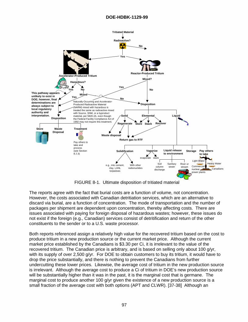
DOE-HDBK-1129-99
97
Yes
Radioactive?
No
Tritiated Material
Reactor-Produced TritiumAccelerator-Produced Tritium
Hazardous?
Yes No
MixedYes
Mixed?
YesNo
No
Disposition
Disposition
Store WasteDisposal
Treatment
Solid Elemental Liquid
Regenerate Store
Waste disposal
Return gas to RTF
Stack Recover
Pay others totake andprocess(see Section8.2.3)
Solidification
e.g., into cement,clay, LANLtorpedoes
With otherradionuclides
Vaporize Liquid releaseto environment
Storage Pay othersto take
Light WaterHeavy Water
CanadiansCommercialnuclearpower plants
Soilcolumn
discharge
Sanitarysewer
River orstream
Naturally-Occurring and Accelerator-Produced Radioactive Material(NARM) mixed with hazardous istreated the same as radioactive mixedwith Source, SNM, or a byproductmaterial, per 5820.2A, even thoughthe Federal Facility Compliance Act of1992 may not require this treatment.
This pathway appearsunlikely to exist inDOE; however, finaldeterminations arealways subject tolocal regulatoryauthority andinterpretation.
evaporate stack
FIGURE 8-1. Ultimate disposition of tritiated material
The reports agree with the fact that burial costs are a function of volume, not concentration.However, the costs associated with Canadian detritiation services, which are an alternative todiscard via burial, are a function of concentration. The mode of transportation and the number ofpackages per shipment are dependent upon concentration, thereby affecting costs. There areissues associated with paying for foreign disposal of hazardous wastes; however, these issues donot exist if the foreign (e.g., Canadian) services consist of detritification and return of the otherconstituents to the sender or to a U.S. waste processor.
Both reports referenced assign a relatively high value for the recovered tritium based on the cost toproduce tritium in a new production source or the current market price. Although the currentmarket price established by the Canadians is $3.30 per Ci, it is irrelevant to the value of therecovered tritium. The Canadian price is arbitrary, and is based on selling only about 100 g/yr,with its supply of over 2,500 g/yr. For DOE to obtain customers to buy its tritium, it would have todrop the price substantially, and there is nothing to prevent the Canadians from furtherundercutting these lower prices. Likewise, the average cost of tritium in the new production sourceis irrelevant. Although the average cost to produce a Ci of tritium in DOE’s new production sourcewill be substantially higher than it was in the past, it is the marginal cost that is germane. Themarginal cost to produce another 100 g/yr given the existence of a new production source is asmall fraction of the average cost with both options (APT and CLWR). [37-38] Although an
DOE-HDBK-1129-99
98
accurate estimation of these costs cannot be made until after the new tritium source comes on line,the Canadian marginal cost for their tritium facility is estimated to be about $0.25 per Ci. [39] Itappears that the value of the recovered tritium (i.e., from waste streams; high Ci content processstreams are more economical) is overstated, and that recovery options, even the most cost-effective such as the PMR, cannot be justified on economics alone. Any recovery argumentshould also have an environmental component or a different valuation philosophy for tritium. Onesuch valuation model proposed by Mike Rogers of Mound is based on the opportunity costs ofdelaying the construction of the new production source. If the quantity of recovered tritium coulddelay the construction of the new production source, there is a savings to the Treasury of the timevalue of money. If government accounting practices are cognizant of such benefits, a quantifiedbasis can be estimated to ascertain economic viability for recovery system construction (thesecash outflows offset, to a small extent, the cash inflow savings). This valuation technology fortritium could only be used up to the time that a new production source comes onstream.Thereafter, a comparison of marginal costs of the recovery system and new production sourcecould be made to decide on continuing with recovery operations.
In the absence of a Department-wide policy on tritium recovery, DOE sites with tritium oxide andtritiated water inventories should consider their EDLs based on the site-specific conditions andneeds. The implication of the preceding discussion is that once tritium goes into the oxide form, itis difficult to justify on an economic basis alone using any recovery method. The fact thateconomic recovery of tritium from oxide form is not easily justified should be an important factor indesigning tritium facilities.
8.3 Waste Packaging
DOE, DOT and NRC requirements for radioactive waste packaging are presented in Chapter 7.
Barriers, in addition to the outer packaging, should be considered to inhibit tritium migration fromwaste packages. The only significant difference associated with packaging of waste for shipmentversus packaging of any other quantity of nuclear material for shipment is that Type B quantities ofwaste may be packaged in Type A containers at the waste generation site and shipped to thewaste site overpacked in Type B containers such as the Trupact II. During shipment, the wastepackage must meet the current DOE and DOT regulations for shipment of the form and quantity ofradioactive material; i.e., Limited Quantity, Type A Quantity, Type B Quantity. After receipt at thewaste disposal site, the type A package containing the Type B quantity of low-level (radioactive)waste is removed from the Type B package. The Type B package is then returned to the shipperfor reuse, and the Type A package containing the Type B quantity of tritium is stored at the wastedisposal site along with the other low-level waste.
The waste acceptance requirements are a little different at each waste disposal site. The followingis a list of things to be considered before waste is packaged.
• Free Liquids: Waste should contain as little free liquid as reasonably achievable, but under noconditions shall the free liquid volume exceed 0.5 percent by volume of the external container.
• Absorbent: If absorbent material is used to solidify liquid in the waste, then the quantity ofabsorbent material added to the waste must be sufficient to absorb a minimum of twice thevolume of the liquid.
• Particulate: Waste in particulate form should be immobilized, and, if immobilization isimpractical, other acceptable waste packaging shall be used, such as overpacking: drum
DOE-HDBK-1129-99
99
containing particulate enclosed in another drum; and wooden or steel box with particulateenclosed in a 6-mil sealed plastic liner inside the box.
• Gases: Pressure in the waste box shall not exceed 1.5 atmospheres absolute at 20oC.Compressed gases as defined by 49 CFR 173.300 are generally not accepted for disposalunless the valve mechanism has been removed or it is obvious that the container has beenpunctured.
• Containers, Vessels, Manifolds: Containers, vessels, and manifolds that have been exposed totritium and should remain sealed, must be certified to contain no pressure greater than 1.5atmospheres
* absolute prior to packaging as waste.
• Stabilization: Where practical, waste should be treated to provide a more structurally andchemically stable waste form.
• Etiologic Agents: LLW containing pathogens, infectious wastes, or other etiologic agents asdefined in 49 CFR 173.386 are generally not accepted.
• Chelating Agents: Chelating or complexing agents at concentrations greater than 1 percent byweight of the waste form are generally not accepted.
• Polychlorinated Biphenyls: Polychlorinated Biphenyls contaminated LLW is generally notaccepted unless the Polychlorinated Biphenyls concentration is less than 50 ppm
• Explosives and Pyrophorics: Material in a form that may explode spontaneously or combust ifthe container is breached is generally not accepted for disposal.
8.4 Waste Shipping
The shipping requirements for Class 7 (radioactive) material can be found in Section 6.1. If thetritium waste is mixed with RCRA constituents, a hazardous waste manifest and Land DisposalRestriction notification is required for offsite shipments. See Section 7.1 for RCRA pre-transportrequirements associated with mixed waste. In addition, any containers less than 110 gallons incapacity must be marked as hazardous waste in accordance with 40 CFR 262.32.
During shipment, the waste package must meet the current DOE and DOT regulations forshipment of the form and quantity of radioactive material; i.e. Limited Quantity, Type A Quantity,and Type B Quantity.
* DOE Order 5820.2A, from which the 1.5 atmospheres requirement is taken, has been superceded by DOEO 435.1, but in the revised Order the 1.5 atmosphere requirement only applies to initial gaseous forms(“Low-level waste in a gaseous form must be packaged such that the pressure does not exceed 1.5atmospheres absolute at 20°C.”) Another requirement from DOE O 435.1 states, “When waste is packaged,vents or other measures should be provided if the potential exists for pressurizing containers or generatingflammable or explosive concentrations of gases within the waste package.

DOE-HDBK-1129-99
100
This page is intentionally blank.
DOE-HDBK-1129-99
A-1
APPENDIX A: USEFUL NUMERICAL VALUES
A.1 General Data• 1 becquerel (Bq) = 1 disintegration/second = 2.7 x 10⁻¹¹ Ci• 1 Ci = 3.7 x 10¹⁰ disintegrations/second = 3.7 x 10¹⁰ Bq = 37 GBq• Avogadro’s Number = 6.023 x 10²³ molecules/mole• STP conditions: 760 Torr, and 0oC (1 atm and 273K)• 1 mole of ideal gas at STP = 22.414 L at 0° C, and approximately 24.2 L/mole at room
temperature• 1 Sievert (Sv) = 8.38 roentgens = 100 rem
A.2 General Tritium Data• Tritium decays to 3He + beta + neutrino• Half-life of tritium (Scientific purposes) = 12.323 ± 0.004 years (4500.88 ± 1.46 days)
Half-life of tritium (Accountability purposes) = 12.33 +/- 0.06 years (DOE M 474.1-2,Figure IV-2)
• Tritium decay factor = 0.99984601/day• Maximum beta energy of decay (E max.) = 18.6 keV• Mean beta energy of decay (E mean) = 5.69 keV• Volume of 1 Ci of tritium at STP = 0.386 mL• Tritium gas = 9619 Ci/g• T2 gas contains 58023 Ci/mole• 2.589 Ci/cm3 of T2 at STP• Diameter of a tritium atom (approximate) = 1.1 Angstroms• Dissociation energy, T2 to 2T = 4.59 eV• Ionization energy, T to T+ + e- = 13.55 eV• Atomic weight = 3.01605• Gram molecular weight of tritium = 6.0321 g• Grams tritium/liter at STP = 0.269122 g/L• Liters/gram of tritium at STP = 3.71579 L/g• Boiling point of tritium at 1 atmosphere = 25.0 K• T2 gas, at 1 atmosphere pressure and 25oC = 2.372 Ci/cm3
• Tritiated water, T2O = 3200 Ci/cm3
A.3 Regulatory Quantities• Type B Quantity = > 1080 Ci• Type A Quantity = > 0.108 to <1080 Ci depending on form• Limited Quantity = < 21.6 Ci of tritium in gaseous form
< 1.08 Ci of tritium in solid form < 1 Ci of tritium at a concentration of > 1 Ci/L liquid < 100 Ci at a concentration of > 0.1 to < 1 Ci/L liquid < 1000 Ci at a concentration of < 0.1 Ci/L liquid
• A2 Quantity = 40 TBq (1080 Ci)• Limited Quantity Excepted Package Requirement for tritium
− Radiation level < 0.005 mSv/hr (0.5 mrem/hr)− Quantity of radioactive material < limit in 49 CFR 173.425
DOE-HDBK-1129-99
A-2
− Package meets general design requirements for radioactive material packaging from49 CFR 173.410
− Nonfixed/removable contamination on the external surface of the package is < limitin 49 CFR 173.443 (0.41 Bq of tritium/cm2 or 22 disintegrations/min (dpm)/cm2 fortritium)
− Outside of inner or outer packaging is marked “Radioactive”• Low Specific Activity (LSA) A quantity of Class 7 (radioactive) material with limited
specific activity− LSA-I
� Earth, concrete, rubble or other debris = 4 x 10⁵ TBq of tritium/g (0.001 Ci oftritium/g, 1 Ci of tritium/kg or 2.2 lb/Ci of tritium)
− LSA-II� Tritium-Contaminated Water up to: 0.8 TBq of tritium/L (20.0 Ci/L)� Solids and Gases up to 0.004 TBq of tritium/g (0.1 Ci/g, 100 Ci/kg)� Liquids 4 x 10⁴ TBq of tritium/g (0.01 Ci/g, 10 Ci/kg)
− LSA-III� Solids, consolidated wastes, or activated material that meet 49 CFR 173.468
water leach test; and� Uniformly distributed in a collection of solid objects or uniformly distributed in
solid compact binding agent; i.e., concrete, bitumen, ceramic, etc.� Relatively insoluble or intrinsically contained in relatively insoluble material such
that, under loss of packaging and placed in water for seven days, would notexceed 4 TBq of tritium (108 Ci of tritium)
� The average specific activity of the solid does not exceed 0.08 TBq of tritium/g(2.16 Ci/g)
• SCO (Surface Contaminated Object) Non-radioactive solid objects with Class 7(radioactive) materials distributed on the surfaces− SCO-I
� Nonfixed contamination on accessible surface averaged over 300 cm2 is < 4 Bqof tritium/cm2 (104 µCi/cm2 )
� Fixed contamination on the accessible surface averaged over 300 cm2 is < 4 x10⁴ Bq of tritium/cm2 (1 µCi/cm2 )
� Nonfixed plus fixed contamination on the inaccessible surface averaged over 300cm2 is < 8 x 10⁵ Bq of tritium/cm2 (20 µCi/cm2)
− SCO-IISolid object on which limit for SCO-I is exceeded and meets the following:
� Nonfixed contamination of accessible surface averaged over 300 cm2 is < 400 Bqof tritium/cm2 (10-2 µCi/cm2).
� Fixed contamination of accessible surface averaged over 300 cm2 is < 8 x 10⁵ Bqof tritium/cm2 (20 µCi/cm2).
� Nonfixed plus fixed contamination of accessible surface averaged over 300 cm2
is < 8 x 10⁵ Bq of tritium/cm2 (20 µCi/cm2).• Type A Packages limited to 40 TBq of tritium (< 1080 Ci) per package• Type B Packages for quantities > 40 TBq of tritium (> 1080 Ci) per package• Graded Safeguards Program
− Category III: Weapons or test components, containing reportable quantities > 50 g T2
with isotopic fraction T2 > 20 percent− Category IV: All other reportable quantities
DOE-HDBK-1129-99
A-3
• Facility Categories− Hazard Category 1: Category A reactors and facilities designated by PSO.− Hazard Category 2: > 30 g of tritium− Hazard Category 3: > 1.6 but < 30 g of tritium− Radiological Facility:< 1.6 g of tritium
A.3 Tritium Dose and Exposure Data• Biological half-life = 8 to 12 days (oxide); biological half-life of tritides is currently being
researched• Derived Air Concentration (DAC)
− DAC for HTO = 21.6 µCi/m3 = 2 x 10⁻⁵ µCi/mL = 8 x 10⁵ Bq/m3
− DAC for HT = 540,000 µCi/m3 = 5 x 10⁻¹ µCi/mL = 2 x 10¹⁰ Bq/m3
No DACs currently exist for tritides; efforts are underway to develop these• Dose Conversion Factor (DCF)
− DCF = 0.063 mrem/µCi (inhalation)− DCF = 0.095 mrem/µCi (inhalation plus 50 percent allowance for skin absorption)
• Annual Limit of Intake (ALI)− ALI for HTO = 80,000 µCi− An initial exposure equilibrium urine count of 1 µCi/L equates to approximately a
3-mrem dose.− A urine count of 50 µCi/L for a year equates to approximately a 5,000-mrem dose.− Breathing 21.6 µCi/m3 HTO in air for 8 hours/day, 50 week/year will result in a dose
of approximately 5,000 mrem.− Tritiated water is approximately 25,000 times more hazardous than tritium gas
because of rapid uptake mechanisms.• Tritium Beta Particles
− Range in Air = 4.5 to 6 mm− Range in Water = 0.0005 cm− Range in Tissue = 0.0007 cm− Radiation, 1 mCi in man (70 kg) = 0.0044 rem/day− Maximum Penetration = 0.6 mg/cm3
A.4 Tritium Container Data• WSRC Hydride Transport Vessel (HTV)
− Reusable container for transporting up to 18 grams of tritium− Shipped in UC-609− Dual port, flow through capable− One female, one male port, Cajon® SS-4-VCR− Tritium stored as uranium tritide− Contains 493 g depleted uranium− Stoichiometry Maximum 1:2.9− Weight 9.3 lb− Height 9.995 in− Diameter 4.6 in− Volume 690 cm3
− Maximum normal operating temperature = 450oC− Pressure Limit at Maximum normal operating temperature = 2.9 psia− Tritium vapor pressure as a function of temperature at U:T = 1:2.9
DOE-HDBK-1129-99
A-4
− Dissociation Equations� Log Patm = -4038.2/T + 6.074, Patm = 10-4038.2/T +6.074
� Log Ppsia = -4038.2/T + 7.2413, Ppsia = 10-4038.2/T+7.2413
• WSRC Product Vessel (PV)− Reusable container for transporting 10 g of tritium in liquid form− Shipped in UC-609− Volume 21 L− Maximum pressure 1,200 torr− Height 30.5 in− Diameter 9.875 in− Weight 44 lb− Single valve, Nupro® SS-4-HS-TW− Male Nut, Cajon® SS-4-VCR-4− Female Cap Cajon® SS-4-VCR-CP
A.5 Other Data• Calorimeter Factor
− 3.0657 +/- 0.009 g of tritium per Watt− 0.3240 +/- 0.0009 Watts/g of tritium
• ANSI N14.5-87 Leakage Test− < 1 x 10⁻⁷ cm3 /s 4He
DOE-HDBK-1129-99
B-1
APPENDIX B: DEFINITIONS
Airborne radioactivity area – Any area where the measured concentration of airborneradioactivity, above natural background, exceeds or is likely to exceed 10 percent of the derivedair concentration (DAC) values listed in Appendix A or Appendix C of this part (10 CFR 835).(DOE 10 CFR 835)
As low as reasonably achievable (ALARA) – A phrase (acronym) used to describe anapproach to radiation protection to control or manage exposures (both individual and collectiveto the work force and the general public) and releases of radioactive material to the environmentas low as social, technical, economic, practical, and public policy considerations permit. (DOE5400.5)
Below regulatory concern – A definable amount of low-level waste that can be deregulatedwith minimal risk to the public. (DOE 5820.2A)
Best available technology for radioactive effluent control (BATREC) – The preferredeffluent treatment technology, selected after taking into account factors related to technology,economics, public policy, and other parameters. As used in this part, the BATREC is not aspecific level of treatment, but is the conclusion of a selection process in which severalalternative effluent treatment technologies are evaluated. It has evolved from the BAT conceptdescribed in DOE 5400.5. This process, however, is not applied to tritium. (Draft DOE 834)
Buffer zone – The smallest region beyond the disposal unit that is required as controlled spacefor monitoring and for taking mitigative measures, as may be required. (DOE 5820.2A)
Byproduct material – (1) any radioactive material (except special nuclear material) yielded inor made radioactive by exposure to the radiation incident to the process of producing or utilizingspecial nuclear material, and (2) the tailings or wastes produced by the extraction orconcentration of uranium or thorium from any ore processed primarily for its source materialcontent. (Atomic Energy Act of 1954, 42 USC 2011)
Certified waste – Waste that has been confirmed to comply with disposal site wasteacceptance criteria (e.g., the Waste Isolation Pilot Plant-Waste Acceptance Criteria fortransuranic waste, the DOE/NVO-325 criteria) under an approved certification program. (DOE5820.2A)
Confinement system
1. Any equipment, structure, or system, which limits the release and/or dispersion of ahazardous/radioactive material within a facility. Examples are fume hoods, air locks,ventilation systems, and may include containment and recovery systems. Confinementsystems may consist of multiple techniques and barriers depending upon the quantity oftritium involved and the consequences of an uncontrolled release. (U.S. DOE Tritium FocusGroup)
2. A collection of barriers that can satisfy a specified leak criterion contingent upon operation ofits ancillary (active) system. An example of a confinement system is a glovebox and itsassociated cleanup system. (DOE-HDBK-1129-99)
3. The assembly of components of the packaging intended to retain the radioactive materialduring transport. (10 CFR Part 71)
DOE-HDBK-1129-99
B-2
4. An area having structures or systems from which releases of hazardous materials arecontrolled. Primary confinement systems are process enclosures (gloveboxes, conveyors,transfer boxes, and other spaces normally containing hazardous materials). Secondaryconfinement areas surround one or more primary confinement systems (operating areacompartments). (DOE O 435.1)
Containment system
1. Any equipment, structure, or systems that serve as an integral and essentially leak tightbarrier against the uncontrolled release of hazardous/radioactive material to the environmentand other areas within the facility. Examples include process piping, sealed containers,tanks, gloveboxes, and any other closed loop system, which holds the material for possiblerecovery of tritium. (U.S. DOE Tritium Focus Group)
2. A collection of passive barriers that can satisfy a specified leak criterion without operation ofany ancillary equipment. An example of a containment system is a series of piping andvessels enclosing tritium gas operations. (DOE-HDBK-1129-99)
3. A structurally closed barrier and its associated systems (including ventilation) between areascontaining hazardous materials and the environment or other areas in the nuclear facilitythat are normally expected to have levels of hazardous materials lower than allowableconcentration limits. A containment barrier is designed to remain closed and intact during alldesign basis accidents. (DOE O 435.1)
Derived Air Concentration (DAC) – For the radionuclides listed in Appendix A of 10 CFR 835,the airborne concentration that equals the Annual Limit of Intake (ALI) divided by the volume ofair breathed by an average worker for a working year of 2,000 hours (assuming a breathingvolume of 2400 m3). (DOE 10 CFR 835)
Derived Concentration Guide (DCG) – The concentration of a radio nuclide in air or waterthat, under conditions of continuous exposure for one year by one exposure mode (i.e.,ingestion of water, submersion in air, or inhalation), would result in an effective dose equivalentof 100 mrem (1 mSv). DCGs do not consider decay products when the parent radionuclide isthe cause of the exposure. (DOE 5400.5)
DOE/DOT Type A, approved shipping package – For the purpose of this text, these arepackages that can be used for the transport of Type A quantities of radioactive materials. Thetwo typical packages used for solids are metal 55-gallon drums with full removable lids andmetal boxes 4 feet wide by 4 feet high and 7 feet long with removable lids. DOT 7A packagesmay be fabricated in almost any size to fit special needs like packaging of gloveboxes.
Facility segmentation – The concept of independent facility segments should be applied wherefacility features preclude bringing material together or causing harmful interaction from acommon severe phenomenon. Therefore, the standard permits the concept of facilitysegmentation provided the hazardous material in one segment could not interact withhazardous materials in other segments. For example, independence of HVAC and piping mustexist in order to demonstrate independence for facility segmentation purposes. Thisindependence must be demonstrated and places the “burden of proof” on the analyst.Additionally, material contained in DOT Type B shipping containers (with or without overpack)may also be excluded from summation of a facility’s radioactive inventory if the Certificates ofCompliance are kept current and the materials stored are authorized by the Certificate.However, Type B containers without overpack should have heat protection provided by thefacility’s fire suppression system. (DOE-STD-1027-92, Rev. 1)
DOE-HDBK-1129-99
B-3
Free liquids – Liquids that readily separate from the solid portion of a waste under ambienttemperature and pressure. (DOE 5820.2A)
Hazard Category 1 – A facility in which the hazard analysis shows the potential for significantoff-site consequences. Category A reactors and facilities designated by PSO. Regardless ofthe quantity of tritium, a facility that handles only tritium is not a Hazard Category 1 facilityunless it is designated so by the PSO. (DOE-STD-1027-92, Rev. 1)
Hazard Category 2 – A facility in which the hazard analysis shows the potential for significanton-site consequences. Facilities with the potential for nuclear criticality events or with sufficientquantities of hazardous material and energy, which would require on-site emergency planningactivities. The threshold tritium inventory for a tritium facility to be designated as a HazardCategory 2 facility is 30 grams or 300,000 Ci. (DOE-STD-1027-92, Rev. 1)
Hazard Category 3 – A facility in which the hazard analysis shows the potential for onlysignificant localized consequences. Facilities included are those with quantities of hazardousradioactive materials that meet or exceed values in Table A.1 of DOE-STD-1027-97. Thethreshold for tritium is specified as 1.6 grams or 16,000 Ci. (DOE-STD-1027-92, Rev. 1)
Hazardous materials – Those materials that are toxic, explosive, flammable, corrosive, orotherwise physically or biologically health-threatening. (DOE 5480.22)
Hazardous wastes – Those wastes that are designated hazardous by EPA regulations(40 CFR 261). (DOE 5820.2A)
Leak tight – A leakage rate that complies with ANSI N14.5-1987, which is less than or equal to1 x 10-7 std cm3/sec. (standard cubic centimeters of gas per second) across a pressure gradientof 1.0 atmosphere. This rate is equivalent to the leakage of 4 x 10-12 moles of air or helium persecond. (DOE-STD-3013-94)
Low-level waste – Waste that contains radioactivity and is not classified as high-level waste,transuranic waste, or spent nuclear fuel or 11e(2) byproduct material as defined by this Order(5820.2A). Test specimens of fissionable material irradiated for research and developmentonly, and not for the production of power or plutonium, may be classified as low-level waste,provided the concentration of transuranic is less than 100 nCi/g. (DOE 5820.2A)
Mixed waste – Waste containing both radioactive and hazardous components as defined by theAtomic Energy Act and the Resource Conservation and Recovery Act, respectively. (DOE5820.2A)
Nonreactor nuclear facility – Those activities or operations that involve radioactive and/orfissionable materials in such form and quantity that a nuclear hazard potentially exists to theemployees or the general public. Included are activities or operations that
• Produce, process, or store radioactive liquid or solid waste, fissionable materials, ortritium;
• Conduct separations operations;• Conduct irradiated materials inspection, fuel fabrication, decontamination, or recovery
operations;• Conduct fuel enrichment operations;
DOE-HDBK-1129-99
B-4
• Perform environmental remediation or waste management activities involving radioactivematerials.
Incidental use and generating of radioactive materials in a facility operation (e.g., check andcalibration sources, use of radioactive sources in research and experimental and analyticallaboratory activities, electron microscopes, and X-ray machines) would not ordinarily require thefacility to be included in this definition. Accelerators and reactors and their operations are notincluded. The application of any rule to a nonreactor nuclear facility should be applied using agraded approach. (DOE 5400.5)
Nuclear facility – Reactor and nonreactor nuclear facilities. DOE-STD-1027-92 definesinventory thresholds for DOE Order 5480.23 compliance and resulting applicability of nuclearfacility requirements.
Primary containment – The first barrier to an uncontrolled release of hazardous/radioactivematerial to the environment and/or other areas in the facility. The barrier may/may not serve forcontainment of the radioactive material. (U.S. DOE Tritium Focus Group)
Primary containment vessel – The outermost sealed container intended for safe storage.When used as the outermost container for storage, it would also be used for shipping. (DOE-STD-3013-94)
Protective Action Guides (PAGs) – Projected numerical dose values established by EPA,DOE, or States for individuals in the population. These values may trigger protective actionsthat would reduce or avoid the projected dose.
Radioactive waste – Solid, liquid, or gaseous material that contains radionuclides regulatedunder the Atomic Energy Act of 1954, as amended, and of negligible economic valueconsidering costs of recovery. (DOE 5820.2A)
Radiological area – Any area within a controlled area which must be posted as a “radiationarea,” “high radiation area,” “very high radiation area,” “contamination area,” “high contaminationarea,” or “airborne radioactivity area” in accordance with 835.603 (10 CFR 835). (DOE10 CFR 835)
Radiological facilities
1. Facilities that do not meet or exceed Category 3 threshold criteria specified in DOE STD-1027-92, Rev. 1, Table A.1, but still possess some amount of radioactive material may beconsidered Radiological Facilities. The Category 3 threshold quantity of tritium is 16,000curies. Radiological Facilities are exempt from the requirements of DOE 5480.23, but arenot exempt from other safety requirements. (DOE-STD-1027-92, Rev. 1)
2. Radiological facilities are those with an inventory of radiological materials below the levelsas defined in DOE-STD-1027-92, (currently 16,000 curies) but above the reportable quantityvalue (currently 100 curies) listed in Appendix B to Table 302.4 (per 40 CFR 302). Thislower limit of 100 curies is applicable to EM and DP facilities. (DOE-EM-STD-5502-94)
Receiving and/or shipping area – An area or two different areas that have been designated asradioactive materials Receiving and/or Shipping Areas and have been posted for the receipt andshipment of packaged radioactive materials.
DOE-HDBK-1129-99
B-5
Receiving and/or shipping, storage area – An area or two different areas that have beendesignated as the Receiving and/or shipping Area, Storage Area and have been posted for thestorage of packaged incoming and outgoing shipments of radioactive materials.
Reference man – A hypothetical aggregation of human (male and female) physical andphysiological characteristics arrived at by international consensus (ICRP Publication 23). Thesecharacteristics may be used by researchers and public health workers to standardize results ofexperiments and to relate biological insult from ionizing radiation to a common base. The“reference man” is assumed to inhale 8,400 cubic meters of air in a year and to ingest 730 litersof water in a year. (DOE 5400.5)
Release of property – As used in DOE Order 5400.5, it is the exercising of DOE’s authority torelease property from its control after confirming that residual radioactive material (over whichDOE has authority) on the property has been determined to meet the guidelines for residualradioactive material in Chapter IV of DOE Order 5400.5 or any other applicable radiologicalrequirements. There may be instances in which DOE or other authority will impose restrictionson the management and/or use of the property if the residual radioactive material guidelines ofChapter IV of DOE Order 5400.5 are not met or if other applicable Federal, state, or localrequirements cause the imposition of such restrictions. (DOE 5400.5)
Safety analysis – A documented process that:• Provides systematic identification of hazards within a given DOE operation• Describes and analyzes the adequacy of the measures taken to eliminate, control, or
mitigate identified hazards• Analyzes and evaluates potential accidents and their associated risks. (DOE Order
5400.5)
Safety analysis report (SAR) – A report that documents the adequacy of safety analysis for anuclear facility to ensure that the facility can be constructed, operated, maintained, shut down,and decommissioned safely and in compliance with applicable laws and regulations. (DOE5400.5)
Safety-class structures, systems, and components (safety-class SSCs). Systems,structures, or components including primary environmental monitors and portions of processsystems, whose failure could adversely affect the environment, or safety and health of the publicas identified by safety analyses (DOE 5480.30)
Safety-significant structures, systems, and components (safety-significant SSCs).Structures, systems, and components not designated as safety-class SSCs, but whosepreventive or mitigative function is a major contributor to defense in depth (i.e., prevention ofuncontrolled material releases) and/or worker safety as determined from hazard analysis.
Secondary containment – The second barrier to an uncontrolled release of hazardous orradioactive materials to the environment and/or other areas in the facility. The barrier may/maynot serve for containment of the radioactive material. (U.S. DOE Tritium Focus Group)
Sievert – The dose delivered by a point source of 1 mg of radium, enclosed in a platinumcontainer with walls 1/2 mm thick, to a sample at a distance of 1 cm over a period of 1 hour.
Soil column – A system that incorporates an in-situ volume of soil through which liquid wastepercolates from ponds, cribs, seepage basins, or trenches with the primary purpose being to
DOE-HDBK-1129-99
B-6
retain suspended or dissolved radioactive material by absorption, ion exchange, or physicalentrainment. Unless used specifically for radionuclide disposal, areas such as drain fields andnatural ground surfaces or stream beds that may become contaminated as a result of incidentalexposure are not soil columns. (Draft 10 CFR 834)
Source material – (1) uranium, thorium, or any other material which is determined by thecommission pursuant to the provisions of section 61 (42 USC 2091) to be source material; or (2)ores containing one or more of the foregoing materials in such concentration as the Commissionmay by regulation determine from time to time. (Atomic Energy Act of 1954, 42 USC 2011)
Special nuclear material – (1) plutonium, uranium enriched in the isotope 233 or in the isotope235, and any other material which the Commission, pursuant to the provisions of section 51 (42USC 2017) determines to be special nuclear material, but does not include source material; or(2) any material artificially enriched by any of the foregoing, but does not include sourcematerial. (Atomic Energy Act of 1954, 42 USC 2011)
Stochastic effects – Biological effects, the probability, rather than the severity, of which is afunction of the magnitude of the radiation dose without threshold; i.e., stochastic effects arerandom in nature. Nonstochastic effects are biological effects, the severity of which, in affectedindividuals, varies with the magnitude of the dose above a threshold value. (DOE 5400.5)
Storage – Retrievable retention of waste pending disposal. (DOE 5820.2A)
Technical safety requirements (TSRs) – Those requirements that define the conditions, safeboundaries, and the management or administrative controls necessary to ensure the safeoperation of a nuclear facility and to reduce the potential risk to the public and facility workersfrom uncontrolled releases of radioactive materials or from radiation exposures due toinadvertent criticality. A TSR consists of safety limits, operating limits, surveillancerequirements, administrative controls, use and application instructions, and the basis thereof.TSRs were formerly known as Operational Safety Requirements for nonreactor nuclear facilitiesand Technical Specifications for reactor facilities.
Tertiary containment – The third barrier to an uncontrolled release of hazardous or radioactivematerials to the environment and/or other areas in the facility. The barrier may/may not servefor containment of the radioactive material. (U.S. DOE Tritium Focus Group)
Treatment – Any method, technique, or process designed to change the physical or chemicalcharacter of waste to render it less hazardous, safer to transport, store or dispose of, or reducedin volume. (DOE 5820.2A)
Waste container – A receptacle for waste, including any liner or shielding material that isintended to accompany the waste in disposal. (DOE 5820.2A)
Waste package – The waste, waste container, and any absorbent that are intended for disposalas a unit. In the case of surface contaminated, damaged, leaking, or breached waste packages,any overpack shall be considered the waste container, and the original container shall beconsidered part of the waste. (DOE 5820.2A)
DOE-HDBK-1129-99
C-1
APPENDIX C: ASSAY METHODS
There are a number of different assay methods used at the DOE tritium facilities. Most facilitiesneed assay equipment capable of measuring tritium in gaseous, solid, and liquid form.
• Gas Analysis: For assay of gaseous tritium, most facilities use some form of massspectrometer ranging from quadrapole to large sophisticated light isotope drift tube systems.Gas analysis equipment; especially gas analysis equipment which will measure the lowmolecular weight gases like H2, HD, HT, D2, DT and T2 accurately; is very expensive andrequires a high degree of expertise to operate. These systems can cost from fifty to severalhundred thousand dollars.
• Solid (Metal Tritide): Tritium stored in solid form such as a metal tritide must either bedecomposed to return it to the gas form for analysis, or the heat output of the solid causedby the decay of tritium can be measured in a constant heat flow calorimeter. In order to usecalorimetry to measure the tritium quantity, it must be known that the item being assayeddoes not contain any other radioactive component and that no chemical reactions are takingplace in the container. Constant heat flow calorimeters vary in chamber size from a fewcubic centimeters up to a few liters, and the item to be assayed must be small enough to fitinside the calorimeter chamber. The constant heat flow assay process is the most accurateassay method available if the chamber size and item to be assayed are well matched.
• Liquid (HTO, DTO, T2O): Tritium at high concentrations in liquid form is generally measuredusing calorimetry. Low concentrations of tritium in liquid form are generally measured byusing a scintillation counter. A sample of the liquid is mixed in a scintillation cocktail, and thequantity of tritium in the sample is measured.
C.1 Measurement Accuracy and Safeguards and Security
DOE requires that tritium be accounted for to the hundredth of a gram. However, most of theequipment and the techniques used cannot accurately determine the tritium quantity to ahundredth of a gram once the quantity assayed exceeds about one half gram. This appears tobe inconsistent with the DOE accountability requirements. Measurement accuracy better thanthat implied by the previous statement is certainly achieved but requires expensive,sophisticated equipment and world-class operators that are only justified by special processneeds. Even the more sophisticated equipment does not measure the quantity of tritiumaccurately to a hundredth of a gram once the quantity exceeds about five grams. The assaytechnique to be used in an operation or facility should be frankly discussed with DOEsafeguards and security to make sure that it will meet the DOE needs for the facility safeguardsand security category and the activities performed in the facility.
C.2 Tritium Assay Analysis by PVT Mass Spectrometer
The most common method of assaying tritium in gaseous form, i.e., T2, HT, and DT, mixed withother gases such as Ar, N2,, O2, and 3He, is referred to as “PVT mass spec.” The total numberof moles of gas, n, in a container is calculated using the equation,
n = PV/zRT
where P = pressure in the container in torr
DOE-HDBK-1129-99
C-2
V = volume of the container in litersz = compressibility factor (See Table C.1)R = constant = 62.3631 (See below)T = temperature ( K)
In the formula, the container volume (V) is determined ahead of time by measurement using avolume measuring system, or, if no other means is available, it may be calculated from thephysical dimension of the container. The gas pressure (P) and temperature (T) are determinedby measurement with available instruments at the time of the mass spec sampling. R is aconstant, which is a function of the units of pressure and volume used in the equation and isequal to 62.3631 for pressure in torr and volume in liters.
The compressibility factor (z) is a function of gas type, pressure, and temperature and is eitherdetermined from a compressibility table for tritium or estimated using a standard equation suchas
z(T2) = 1 + [(P (torr) x 0.000832)/1000]
This equation is for a temperature of 295 K.
Most operating facilities have established methods for determining the compressibility factor.For those facilities that do not already have these methods established, Table C-1,Table ofTritium Compressibility Factors, may be helpful.
As an example, for a container with a volume of 22.414 L at a pressure of 760 torr and atemperature of 273.15 K (Standard Temperature and Pressure (STP) conditions) the number ofmoles is calculated as follows:
N = PV/zRT= (760 x 22.414)/(1.000 x 62.3631 x 273.15)= 1.0000 mole
Note: z(T2) at 273.15 K = 1.000.
The total moles of gas in the container at any time, t, is the sum of the moles of the individualgases present in the mixture at that time or in equation form:
PV/zRT = n(Moles Total) = n(T2)+n(HT)+n(DT)+n(CT4)+n(qTw)+n(He-3)+n(N2)+ n(O2)+n(Ar)+n(etc.)
The n(qTw) represents a generic tritium-containing component. The “q” in, n(qTw), represents anyother element which may be present, and the “w” represents the number of tritium atoms in themolecule. The n(etc.), represents any generic, non-radioactive, non-tritium component.From this equation, it follows that
PV/zRT = n(Moles Total) = n(Total Moles of Tritium Containing Gases) + n(Total Moles of Non-tritium Gases)
wheren(Total Moles of Tritium Containing Gases) = n(T2) + n(HT) + n(DT) + n(CT4) + n(qTw) + etc.
andn(Total Moles of Non-Tritium Gases) = n(He-3) + n(N2) + n(O2) + n(Ar) + n(etc.) + etc.
The number of moles of tritium in the container is the sum of the number of moles of tritium ineach tritium component. The number of moles of tritium in each tritium component is equal tothe number of moles of the component multiplied by the moles of tritium per mole of component.

DOE-HDBK-1129-99
C-3
The moles of tritium per mole of component is defined as the ratio of the number of tritiumatoms in the component chemical formula to the number of tritium atoms in T2, i.e., 2.
n(Total Moles of Tritium)= 2n(T2) + 1n(HT) + 1n(DT) + 4CT4 + w n(qTw) + etc.2 2 2 2 2
TABLE C-1. Table of tritium compressibility factors at 295 K
Z(T2) = 1 + {[(Patm x 760) x 0.000832]/1000}
P(atm)
z(T2) P(atm)
z(T2) P(atm)
z(T2) P(atm)
z(T2) P(atm)
z(T2) P(atm)
z(T2)
0.0 1.0000 3.0 1.0019 6.0 1.0038 9.0 1.0057 12.0 1.0076 15.0 1.00950.1 1.0001 3.1 1.0020 6.1 1.0039 9.1 1.0058 12.1 1.0077 15.1 1.00950.2 1.0001 3.2 1.0020 6.2 1.0039 9.2 1.0058 12.2 1.0077 15.2 1.00960.3 1.0002 3.3 1.0021 6.3 1.0040 9.3 1.0059 12.3 1.0078 15.3 1.00970.4 1.0003 3.4 1.0021 6.4 1.0040 9.4 1.0059 12.4 1.0078 15.4 1.00970.5 1.0003 3.5 1.0022 6.5 1.0041 9.5 1.0060 12.5 1.0079 15.5 1.00980.6 1.0004 3.6 1.0023 6.6 1.0042 9.6 1.0061 12.6 1.0080 15.6 1.00990.7 1.0004 3.7 1.0023 6.7 1.0042 9.7 1.0061 12.7 1.0080 15.7 1.00990.8 1.0005 3.8 1.0024 6.8 1.0043 9.8 1.0062 12.8 1.0081 15.8 1.01000.9 1.0006 3.9 1.0025 6.9 1.0044 9.9 1.0063 12.9 1.0082 15.9 1.01011.0 1.0006 4.0 1.0025 7.0 1.0044 10.0 1.0063 13.0 1.0082 16.0 1.01011.1 1.0007 4.1 1.0026 7.1 1.0045 10.1 1.0064 13.1 1.0083 16.1 1.01021.2 1.0008 4.2 1.0027 7.2 1.0046 10.2 1.0064 13.2 1.0083 16.2 1.01020.1 1.0001 4.3 1.0027 7.3 1.0046 10.3 1.0065 13.3 1.0084 16.3 1.01031.4 1.0009 4.4 1.0028 7.4 1.0047 10.4 1.0066 13.4 1.0085 16.4 1.01041.5 1.0009 4.5 1.0028 7.5 1.0047 10.5 1.0066 13.5 1.0085 16.5 1.01041.6 1.0010 4.6 1.0029 7.6 1.0048 10.6 1.0067 13.6 1.0086 16.6 1.01051.6 1.0010 4.7 1.0030 7.7 1.0049 10.7 1.0068 13.7 1.0087 16.7 1.01061.8 1.0011 4.8 1.0030 7.8 1.0049 10.8 1.0068 13.8 1.0087 16.8 1.01061.9 1.0012 4.9 1.0031 7.9 1.0050 10.9 1.0069 13.9 1.0088 16.9 1.01072.0 1.0013 5.0 1.0032 8.0 1.0051 11.0 1.0070 14.0 1.0089 17.0 1.01072.1 1.0013 5.1 1.0032 8.1 1.0051 11.1 1.0070 14.1 1.0089 17.1 1.01082.2 1.0014 5.2 1.0033 8.2 1.0052 11.2 1.0071 14.2 1.0090 17.2 1.01092.3 1.0015 5.3 1.0034 8.3 1.0052 11.3 1.0071 14.3 1.0090 17.3 1.01092.4 1.0015 5.4 1.0034 8.4 1.0053 11.4 1.0072 14.4 1.0091 17.4 1.01102.5 1.0016 5.5 1.0035 8.5 1.0054 11.5 1.0073 14.5 1.0092 17.5 1.01112.6 1.0016 5.6 1.0035 8.6 1.0054 11.6 1.0073 14.6 1.0092 17.6 1.01112.7 1.0017 5.7 1.0036 8.7 1.0055 11.7 1.0074 14.7 1.0093 17.7 1.01122.8 1.0018 5.8 1.0037 8.8 1.0056 11.8 1.0075 14.8 1.0094 17.8 1.01132.9 1.0018 5.9 1.0037 8.9 1.0056 11.9 1.0075 14.9 1.0094 17.9 1.01133.0 1.0019 6.0 1.0038 9.0 1.0057 12.0 1.0076 15.0 1.0095 18.0 1.0114
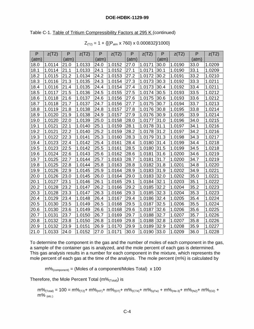
DOE-HDBK-1129-99
C-4
Table C-1. Table of Tritium Compressibility Factors at 295 K (continued)
Z(T2) = 1 + {[(Patm x 760) x 0.000832]/1000}
P(atm)
z(T2) P(atm)
z(T2) P(atm)
z(T2) P(atm)
z(T2) P(atm)
z(T2) P(atm)
z(T2)
18.0 1.0114 21.0 1.0133 24.0 1.0152 27.0 1.0171 30.0 1.0190 33.0 1.020918.1 1.0114 21.1 1.0133 24.1 1.0152 27.1 1.0171 30.1 1.0190 33.1 1.020918.2 1.0115 21.2 1.0134 24.2 1.0153 27.2 1.0172 30.2 1.0191 33.2 1.021018.3 1.0116 21.3 1.0135 24.3 1.0154 27.3 1.0173 30.3 1.0192 33.3 1.021118.4 1.0116 21.4 1.0135 24.4 1.0154 27.4 1.0173 30.4 1.0192 33.4 1.021118.5 1.0117 21.5 1.0136 24.5 1.0155 27.5 1.0174 30.5 1.0193 33.5 1.021218.6 1.0118 21.6 1.0137 24.6 1.0156 27.6 1.0175 30.6 1.0193 33.6 1.021218.7 1.0118 21.7 1.0137 24.7 1.0156 27.7 1.0175 30.7 1.0194 33.7 1.021318.8 1.0119 21.8 1.0138 24.8 1.0157 27.8 1.0176 30.8 1.0195 33.8 1.021418.9 1.0120 21.9 1.0138 24.9 1.0157 27.9 1.0176 30.9 1.0195 33.9 1.021419.0 1.0120 22.0 1.0139 25.0 1.0158 28.0 1.0177 31.0 1.0196 34.0 1.021519.1 1.0121 22.1 1.0140 25.1 1.0159 28.1 1.0178 31.1 1.0197 34.1 1.021619.2 1.0121 22.2 1.0140 25.2 1.0159 28.2 1.0178 31.2 1.0197 34.2 1.021619.3 1.0122 22.3 1.0141 25.3 1.0160 28.3 1.0179 31.3 1.0198 34.3 1.021719.4 1.0123 22.4 1.0142 25.4 1.0161 28.4 1.0180 31.4 1.0199 34.4 1.021819.5 1.0123 22.5 1.0142 25.5 1.0161 28.5 1.0180 31.5 1.0199 34.5 1.021819.6 1.0124 22.6 1.0143 25.6 1.0162 28.6 1.0181 31.6 1.0200 34.6 1.021919.7 1.0125 22.7 1.0144 25.7 1.0163 28.7 1.0181 31.7 1.0200 34.7 1.021919.8 1.0125 22.8 1.0144 25.8 1.0163 28.8 1.0182 31.8 1.0201 34.8 1.022019.9 1.0126 22.9 1.0145 25.9 1.0164 28.9 1.0183 31.9 1.0202 34.9 1.022120.0 1.0126 23.0 1.0145 26.0 1.0164 29.0 1.0183 32.0 1.0202 35.0 1.022120.1 1.0127 23.1 1.0146 26.1 1.0165 29.1 1.0184 32.1 1.0203 35.1 1.022220.2 1.0128 23.2 1.0147 26.2 1.0166 29.2 1.0185 32.2 1.0204 35.2 1.022320.3 1.0128 23.3 1.0147 26.3 1.0166 29.3 1.0185 32.3 1.0204 35.3 1.022320.4 1.0129 23.4 1.0148 26.4 1.0167 29.4 1.0186 32.4 1.0205 35.4 1.022420.5 1.0130 23.5 1.0149 26.5 1.0168 29.5 1.0187 32.5 1.0206 35.5 1.022420.6 1.0130 23.6 1.0149 26.6 1.0168 29.6 1.0187 32.6 1.0206 35.6 1.022520.7 1.0131 23.7 1.0150 26.7 1.0169 29.7 1.0188 32.7 1.0207 35.7 1.022620.8 1.0132 23.8 1.0150 26.8 1.0169 29.8 1.0188 32.8 1.0207 35.8 1.022620.9 1.0132 23.9 1.0151 26.9 1.0170 29.9 1.0189 32.9 1.0208 35.9 1.022721.0 1.0133 24.0 1.0152 27.0 1.0171 30.0 1.0190 33.0 1.0209 36.0 1.0228
To determine the component in the gas and the number of moles of each component in the gas,a sample of the container gas is analyzed, and the mole percent of each gas is determined.This gas analysis results in a number for each component in the mixture, which represents themole percent of each gas at the time of the analysis. The mole percent (m%) is calculated by
m%(component) = (Moles of a component/Moles Total) x 100
Therefore, the Mole Percent Total (m%(Total)) is
m%(Total) = 100 = m%(T2)+ m%(HT)+ m%(DT)+ m%(CT4)+ m%(qTw) + m%(He-3)+ m%(N2)+ m%(O2) +m% (etc.)
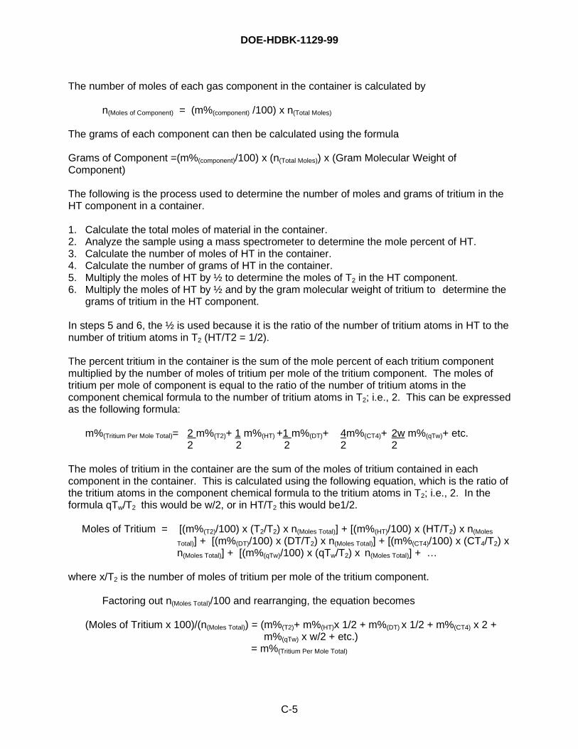
DOE-HDBK-1129-99
C-5
The number of moles of each gas component in the container is calculated by
n(Moles of Component) = (m%(component) /100) x n(Total Moles)
The grams of each component can then be calculated using the formula
Grams of Component =(m%(component)/100) x (n(Total Moles)) x (Gram Molecular Weight ofComponent)
The following is the process used to determine the number of moles and grams of tritium in theHT component in a container.
1. Calculate the total moles of material in the container.2. Analyze the sample using a mass spectrometer to determine the mole percent of HT.3. Calculate the number of moles of HT in the container.4. Calculate the number of grams of HT in the container.5. Multiply the moles of HT by ½ to determine the moles of T2 in the HT component.6. Multiply the moles of HT by ½ and by the gram molecular weight of tritium to determine the
grams of tritium in the HT component.
In steps 5 and 6, the ½ is used because it is the ratio of the number of tritium atoms in HT to thenumber of tritium atoms in T2 (HT/T2 = 1/2).
The percent tritium in the container is the sum of the mole percent of each tritium componentmultiplied by the number of moles of tritium per mole of the tritium component. The moles oftritium per mole of component is equal to the ratio of the number of tritium atoms in thecomponent chemical formula to the number of tritium atoms in T2; i.e., 2. This can be expressedas the following formula:
m%(Tritium Per Mole Total)= 2 m%(T2)+ 1 m%(HT) +1 m%(DT)+ 4m%(CT4)+ 2w m%(qTw)+ etc.2 2 2 2 2
The moles of tritium in the container are the sum of the moles of tritium contained in eachcomponent in the container. This is calculated using the following equation, which is the ratio ofthe tritium atoms in the component chemical formula to the tritium atoms in T2; i.e., 2. In theformula qTw/T2 this would be w/2, or in HT/T2 this would be1/2.
Moles of Tritium = [(m%(T2)/100) x (T2/T2) x n(Moles Total)] + [(m%(HT)/100) x (HT/T2) x n(Moles
Total)] + [(m%(DT)/100) x (DT/T2) x n(Moles Total)] + [(m%(CT4)/100) x (CT4/T2) xn(Moles Total)] + [(m%(qTw)/100) x (qTw/T2) x n(Moles Total)] + …
where x/T2 is the number of moles of tritium per mole of the tritium component.
Factoring out n(Moles Total)/100 and rearranging, the equation becomes
(Moles of Tritium x 100)/(n(Moles Total)) = (m%(T2)+ m%(HT)x 1/2 + m%(DT) x 1/2 + m%(CT4) x 2 +m%(qTw) x w/2 + etc.)
= m%(Tritium Per Mole Total)
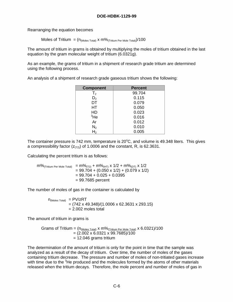
DOE-HDBK-1129-99
C-6
Rearranging the equation becomes
Moles of Tritium = (n(Moles Total) x m%(Tritium Per Mole Total))/100
The amount of tritium in grams is obtained by multiplying the moles of tritium obtained in the lastequation by the gram molecular weight of tritium (6.0321g).
As an example, the grams of tritium in a shipment of research grade tritium are determinedusing the following process.
An analysis of a shipment of research grade gaseous tritium shows the following:
Component PercentT2
D2
DTHTHD3HeArN2
H2
99.7040.1150.0790.0500.0230.0160.0120.0100.005
The container pressure is 742 mm, temperature is 20oC, and volume is 49.348 liters. This givesa compressibility factor (z(T2)) of 1.0006 and the constant, R, is 62.3631.
Calculating the percent tritium is as follows:
m%(Tritium Per Mole Total) = m%(T2) + m%(HT) x 1/2 + m%(DT) x 1/2= 99.704 + (0.050 x 1/2) + (0.079 x 1/2)= 99.704 + 0.025 + 0.0395= 99.7685 percent
The number of moles of gas in the container is calculated by
n(Moles Total) = PV/zRT= (742 x 49.348)/(1.0006 x 62.3631 x 293.15)= 2.002 moles total
The amount of tritium in grams is
Grams of Tritium = (n(Moles Total) x m%(Tritium Per Mole Total) x 6.0321)/100 = (2.002 x 6.0321 x 99.7685)/100 = 12.046 grams tritium
The determination of the amount of tritium is only for the point in time that the sample wasanalyzed as a result of the decay of tritium. Over time, the number of moles of the gasescontaining tritium decrease. The pressure and number of moles of non-tritiated gases increasewith time due to the 3He produced and the molecules formed by the atoms of other materialsreleased when the tritium decays. Therefore, the mole percent and number of moles of gas in
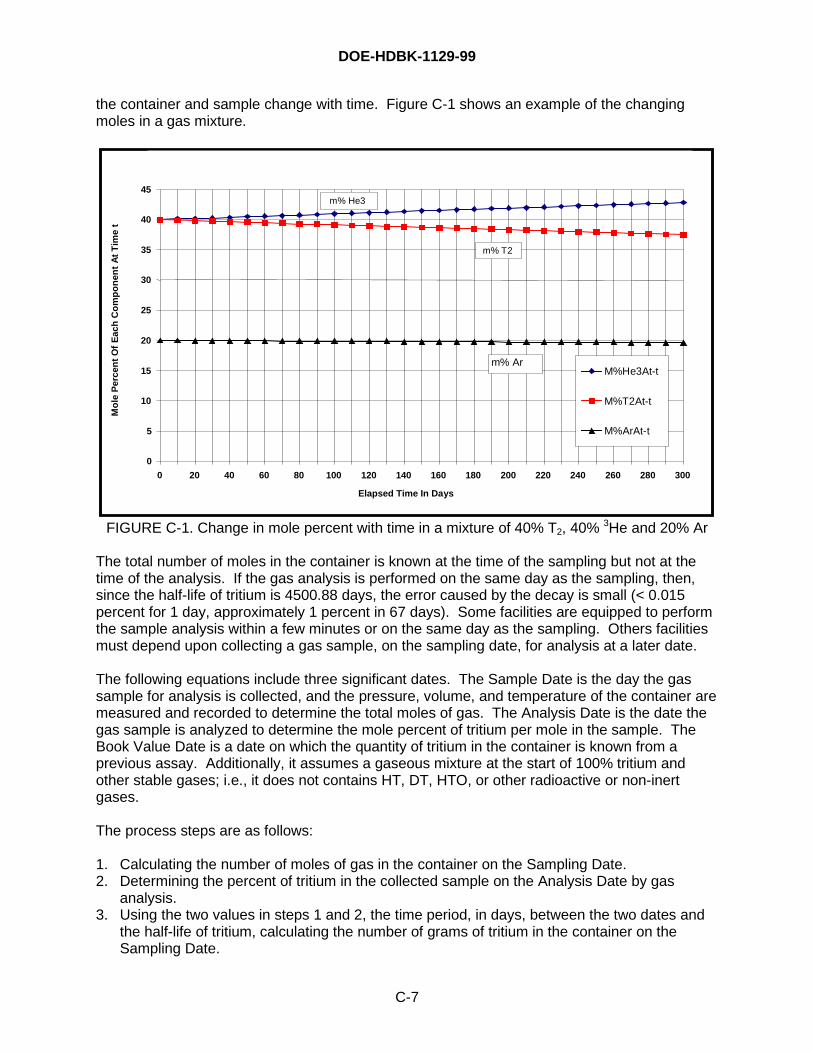
DOE-HDBK-1129-99
C-7
the container and sample change with time. Figure C-1 shows an example of the changingmoles in a gas mixture.
0
5
10
15
20
25
30
35
40
45
0 20 40 60 80 100 120 140 160 180 200 220 240 260 280 300
Elapsed Time In Days
Mo
le P
erce
nt
Of
Eac
h C
om
po
nen
t A
t T
ime
t
M%He3At-t
M%T2At-t
M%ArAt-t
m% Ar
m% T2
m% He3
FIGURE C-1. Change in mole percent with time in a mixture of 40% T2, 40% 3He and 20% Ar
The total number of moles in the container is known at the time of the sampling but not at thetime of the analysis. If the gas analysis is performed on the same day as the sampling, then,since the half-life of tritium is 4500.88 days, the error caused by the decay is small (< 0.015percent for 1 day, approximately 1 percent in 67 days). Some facilities are equipped to performthe sample analysis within a few minutes or on the same day as the sampling. Others facilitiesmust depend upon collecting a gas sample, on the sampling date, for analysis at a later date.
The following equations include three significant dates. The Sample Date is the day the gassample for analysis is collected, and the pressure, volume, and temperature of the container aremeasured and recorded to determine the total moles of gas. The Analysis Date is the date thegas sample is analyzed to determine the mole percent of tritium per mole in the sample. TheBook Value Date is a date on which the quantity of tritium in the container is known from aprevious assay. Additionally, it assumes a gaseous mixture at the start of 100% tritium andother stable gases; i.e., it does not contains HT, DT, HTO, or other radioactive or non-inertgases.
The process steps are as follows:
1. Calculating the number of moles of gas in the container on the Sampling Date.2. Determining the percent of tritium in the collected sample on the Analysis Date by gas
analysis.3. Using the two values in steps 1 and 2, the time period, in days, between the two dates and
the half-life of tritium, calculating the number of grams of tritium in the container on theSampling Date.
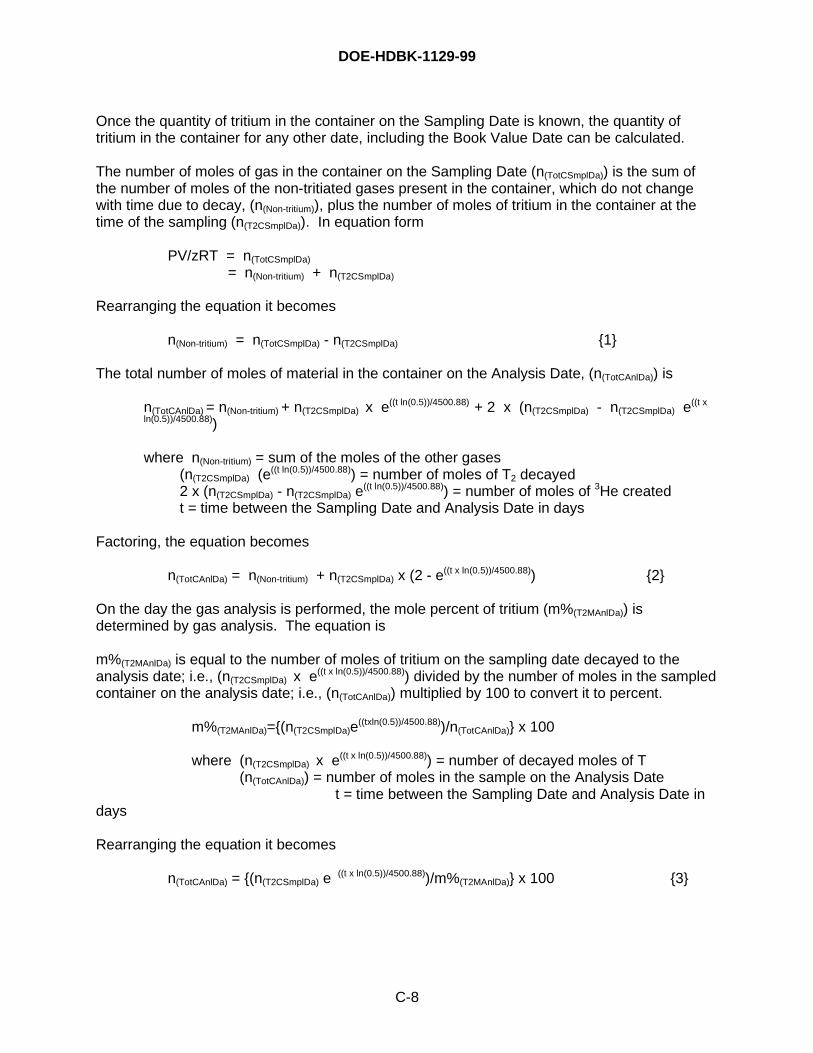
DOE-HDBK-1129-99
C-8
Once the quantity of tritium in the container on the Sampling Date is known, the quantity oftritium in the container for any other date, including the Book Value Date can be calculated.
The number of moles of gas in the container on the Sampling Date (n(TotCSmplDa)) is the sum ofthe number of moles of the non-tritiated gases present in the container, which do not changewith time due to decay, (n(Non-tritium)), plus the number of moles of tritium in the container at thetime of the sampling (n(T2CSmplDa)). In equation form
PV/zRT = n(TotCSmplDa)
= n(Non-tritium) + n(T2CSmplDa)
Rearranging the equation it becomes
n(Non-tritium) = n(TotCSmplDa) - n(T2CSmplDa) {1}
The total number of moles of material in the container on the Analysis Date, (n(TotCAnlDa)) is
n(TotCAnlDa) = n(Non-tritium) + n(T2CSmplDa) x e((t ln(0.5))/4500.88) + 2 x (n(T2CSmplDa) - n(T2CSmplDa) e((t x
ln(0.5))/4500.88))
where n(Non-tritium) = sum of the moles of the other gases(n(T2CSmplDa) (e
((t ln(0.5))/4500.88)) = number of moles of T2 decayed2 x (n(T2CSmplDa) - n(T2CSmplDa) e
((t ln(0.5))/4500.88)) = number of moles of 3He createdt = time between the Sampling Date and Analysis Date in days
Factoring, the equation becomes
n(TotCAnlDa) = n(Non-tritium) + n(T2CSmplDa) x (2 - e((t x ln(0.5))/4500.88)) {2}
On the day the gas analysis is performed, the mole percent of tritium (m%(T2MAnlDa)) isdetermined by gas analysis. The equation is
m%(T2MAnlDa) is equal to the number of moles of tritium on the sampling date decayed to theanalysis date; i.e., (n(T2CSmplDa) x e((t x ln(0.5))/4500.88)) divided by the number of moles in the sampledcontainer on the analysis date; i.e., (n(TotCAnlDa)) multiplied by 100 to convert it to percent.
m%(T2MAnlDa)={(n(T2CSmplDa)e((txln(0.5))/4500.88))/n(TotCAnlDa)} x 100
where (n(T2CSmplDa) x e((t x ln(0.5))/4500.88)) = number of decayed moles of T(n(TotCAnlDa)) = number of moles in the sample on the Analysis Date
t = time between the Sampling Date and Analysis Date indays
Rearranging the equation it becomes
n(TotCAnlDa) = {(n(T2CSmplDa) e ((t x ln(0.5))/4500.88))/m%(T2MAnlDa)} x 100 {3}
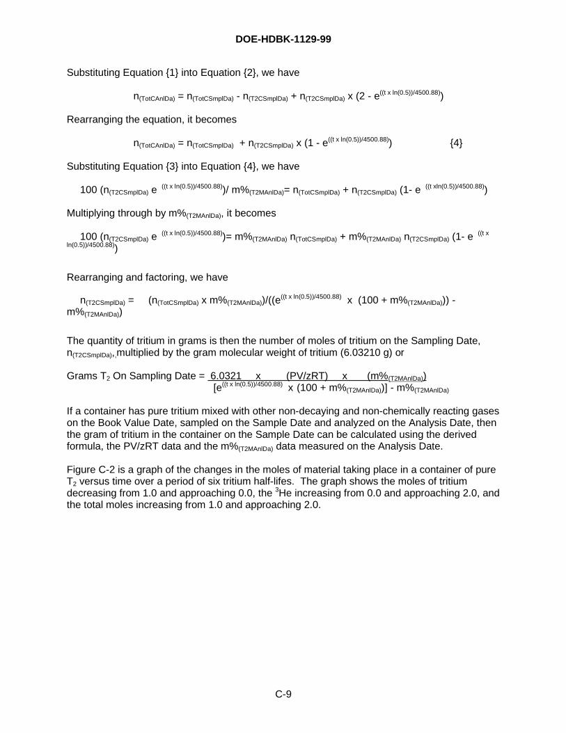
DOE-HDBK-1129-99
C-9
Substituting Equation {1} into Equation {2}, we have
n(TotCAnlDa) = n(TotCSmplDa) - n(T2CSmplDa) + n(T2CSmplDa) x (2 - e((t x ln(0.5))/4500.88))
Rearranging the equation, it becomes
n(TotCAnlDa) = n(TotCSmplDa) + n(T2CSmplDa) x (1 - e((t x ln(0.5))/4500.88)) {4}
Substituting Equation {3} into Equation {4}, we have
100 (n(T2CSmplDa) e ((t x ln(0.5))/4500.88))/ m%(T2MAnlDa)= n(TotCSmplDa) + n(T2CSmplDa) (1- e ((t xln(0.5))/4500.88))
Multiplying through by m%(T2MAnlDa), it becomes
100 (n(T2CSmplDa) e ((t x ln(0.5))/4500.88))= m%(T2MAnlDa) n(TotCSmplDa) + m%(T2MAnlDa) n(T2CSmplDa) (1- e ((t xln(0.5))/4500.88))
Rearranging and factoring, we have
n(T2CSmplDa) = (n(TotCSmplDa) x m%(T2MAnlDa))/((e((t x ln(0.5))/4500.88) x (100 + m%(T2MAnlDa))) -
m%(T2MAnlDa))
The quantity of tritium in grams is then the number of moles of tritium on the Sampling Date,n(T2CSmplDa),,multiplied by the gram molecular weight of tritium (6.03210 g) or
Grams T2 On Sampling Date = 6.0321 x (PV/zRT) x (m%(T2MAnlDa))[e((t x ln(0.5))/4500.88) x (100 + m%(T2MAnlDa))] - m%(T2MAnlDa)
If a container has pure tritium mixed with other non-decaying and non-chemically reacting gaseson the Book Value Date, sampled on the Sample Date and analyzed on the Analysis Date, thenthe gram of tritium in the container on the Sample Date can be calculated using the derivedformula, the PV/zRT data and the m%(T2MAnlDa) data measured on the Analysis Date.
Figure C-2 is a graph of the changes in the moles of material taking place in a container of pureT2 versus time over a period of six tritium half-lifes. The graph shows the moles of tritiumdecreasing from 1.0 and approaching 0.0, the 3He increasing from 0.0 and approaching 2.0, andthe total moles increasing from 1.0 and approaching 2.0.
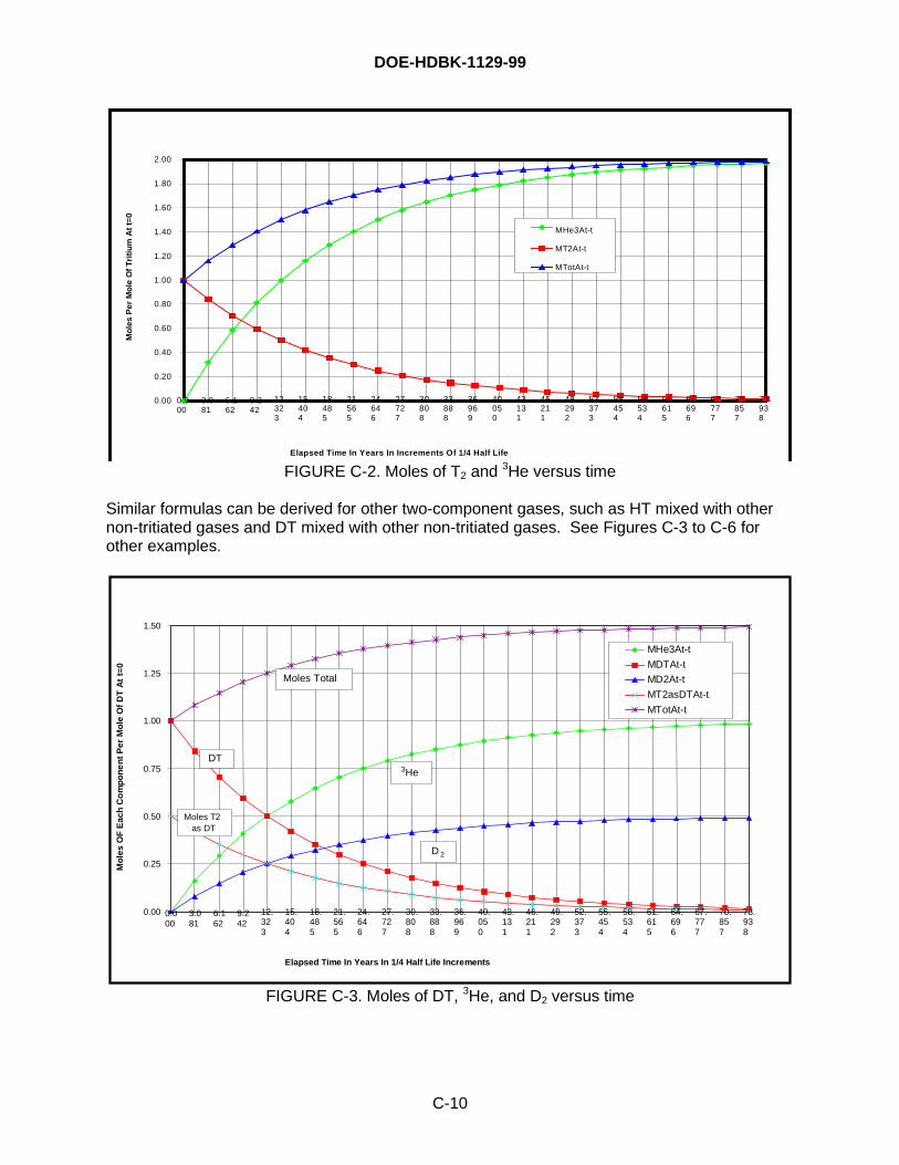
DOE-HDBK-1129-99
C-10
0.00
0.20
0.40
0.60
0.80
1.00
1.20
1.40
1.60
1.80
2.00
0.000
3.081
6.162
9.242
12.323
15.404
18.485
21.565
24.646
27.727
30.808
33.888
36.969
40.050
43.131
46.211
49.292
52.373
55.454
58.534
61.615
64.696
67.777
70.857
73.938
Elapsed Time In Years In Increments Of 1/4 Half Life
Mo
les
Per
Mo
le O
f T
riti
um
At
t=0
MHe3At-t
MT2At-t
MTotAt-t
FIGURE C-2. Moles of T2 and 3He versus time
Similar formulas can be derived for other two-component gases, such as HT mixed with othernon-tritiated gases and DT mixed with other non-tritiated gases. See Figures C-3 to C-6 forother examples.
0.00
0.25
0.50
0.75
1.00
1.25
1.50
0.000
3.081
6.162
9.242
12.323
15.404
18.485
21.565
24.646
27.727
30.808
33.888
36.969
40.050
43.131
46.211
49.292
52.373
55.454
58.534
61.615
64.696
67.777
70.857
73.938
Elapsed Time In Years In 1/4 Half Life Increments
Mo
les
OF
Eac
h C
om
po
ne
nt
Per
Mo
le O
f D
T A
t t=
0
MHe3At-t
MDTAt-t
MD2At-t
MT2asDTAt-t
MTotAt-t
3He
D 2
DT
Moles Total
Moles T2as DT
FIGURE C-3. Moles of DT, 3He, and D2 versus time
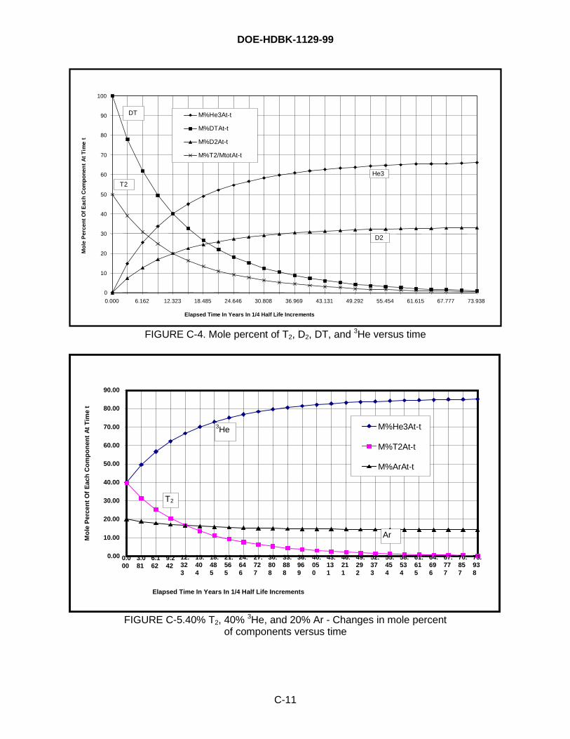
DOE-HDBK-1129-99
C-11
0
10
20
30
40
50
60
70
80
90
100
0.000 6.162 12.323 18.485 24.646 30.808 36.969 43.131 49.292 55.454 61.615 67.777 73.938
Elapsed Time In Years In 1/4 Half Life Increments
Mo
le P
erce
nt
Of
Eac
h C
om
po
nen
t A
t T
ime
t
M%He3At-t
M%DTAt-t
M%D2At-t
M%T2/MtotAt-t
DT
He3
T2
D2
FIGURE C-4. Mole percent of T2, D2, DT, and 3He versus time
0.00
10.00
20.00
30.00
40.00
50.00
60.00
70.00
80.00
90.00
0.000
3.081
6.162
9.242
12.323
15.404
18.485
21.565
24.646
27.727
30.808
33.888
36.969
40.050
43.131
46.211
49.292
52.373
55.454
58.534
61.615
64.696
67.777
70.857
73.938
Elapsed Time In Years In 1/4 Half Life Increments
Mo
le P
erce
nt
Of
Eac
h C
om
po
nen
t A
t T
ime
t
M%He3At-t
M%T2At-t
M%ArAt-t
3He
T2
Ar
FIGURE C-5.40% T2, 40% 3He, and 20% Ar - Changes in mole percentof components versus time
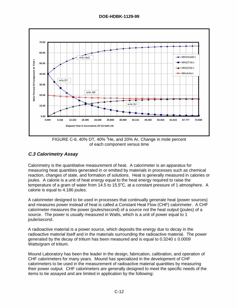
DOE-HDBK-1129-99
C-12
0.00
10.00
20.00
30.00
40.00
50.00
60.00
70.00
0.000 6.162 12.323 18.485 24.646 30.808 36.969 43.131 49.292 55.454 61.615 67.777 73.938
Elapsed Time In Increments Of 1/4 Half Life
Mo
le P
erce
nt
Of
Co
mp
on
ent
At
Tim
e t
M%He3At-t
M%DTAt-t
M%D2At-t
M%ArAt-t
m% He3
m% DT
m% AR
m% D2
FIGURE C-6. 40% DT, 40% 3He, and 20% Ar, Change in mole percentof each component versus time
C.3 Calorimetry Assay
Calorimetry is the quantitative measurement of heat. A calorimeter is an apparatus formeasuring heat quantities generated in or emitted by materials in processes such as chemicalreaction, changes of state, and formation of solutions. Heat is generally measured in calories orjoules. A calorie is a unit of heat energy equal to the heat energy required to raise thetemperature of a gram of water from 14.5 to 15.5oC, at a constant pressure of 1 atmosphere. Acalorie is equal to 4.186 joules.
A calorimeter designed to be used in processes that continually generate heat (power sources)and measures power instead of heat is called a Constant Heat Flow (CHF) calorimeter. A CHFcalorimeter measures the power (joules/second) of a source not the heat output (joules) of asource. The power is usually measured in Watts, which is a unit of power equal to 1joule/second.
A radioactive material is a power source, which deposits the energy due to decay in theradioactive material itself and in the materials surrounding the radioactive material. The powergenerated by the decay of tritium has been measured and is equal to 0.3240 ± 0.0009Watts/gram of tritium.
Mound Laboratory has been the leader in the design, fabrication, calibration, and operation ofCHF calorimeters for many years. Mound has specialized in the development of CHFcalorimeters to be used in the measurement of radioactive material quantities by measuringtheir power output. CHF calorimeters are generally designed to meet the specific needs of theitems to be assayed and are limited in application by the following:
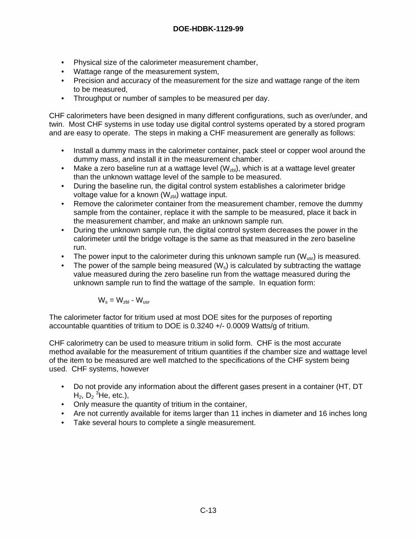
DOE-HDBK-1129-99
C-13
• Physical size of the calorimeter measurement chamber,• Wattage range of the measurement system,• Precision and accuracy of the measurement for the size and wattage range of the item
to be measured,• Throughput or number of samples to be measured per day.
CHF calorimeters have been designed in many different configurations, such as over/under, andtwin. Most CHF systems in use today use digital control systems operated by a stored programand are easy to operate. The steps in making a CHF measurement are generally as follows:
• Install a dummy mass in the calorimeter container, pack steel or copper wool around thedummy mass, and install it in the measurement chamber.
• Make a zero baseline run at a wattage level (Wzbl), which is at a wattage level greaterthan the unknown wattage level of the sample to be measured.
• During the baseline run, the digital control system establishes a calorimeter bridgevoltage value for a known (Wzbl) wattage input.
• Remove the calorimeter container from the measurement chamber, remove the dummysample from the container, replace it with the sample to be measured, place it back inthe measurement chamber, and make an unknown sample run.
• During the unknown sample run, the digital control system decreases the power in thecalorimeter until the bridge voltage is the same as that measured in the zero baselinerun.
• The power input to the calorimeter during this unknown sample run (Wusr) is measured.• The power of the sample being measured (Ws) is calculated by subtracting the wattage
value measured during the zero baseline run from the wattage measured during theunknown sample run to find the wattage of the sample. In equation form:
Ws = Wzbl - Wusr
The calorimeter factor for tritium used at most DOE sites for the purposes of reportingaccountable quantities of tritium to DOE is 0.3240 +/- 0.0009 Watts/g of tritium.
CHF calorimetry can be used to measure tritium in solid form. CHF is the most accuratemethod available for the measurement of tritium quantities if the chamber size and wattage levelof the item to be measured are well matched to the specifications of the CHF system beingused. CHF systems, however
• Do not provide any information about the different gases present in a container (HT, DTH2, D2
3He, etc.),• Only measure the quantity of tritium in the container,• Are not currently available for items larger than 11 inches in diameter and 16 inches long• Take several hours to complete a single measurement.

DOE-HDBK-1129-99
C-14
This page is intentionally blank.
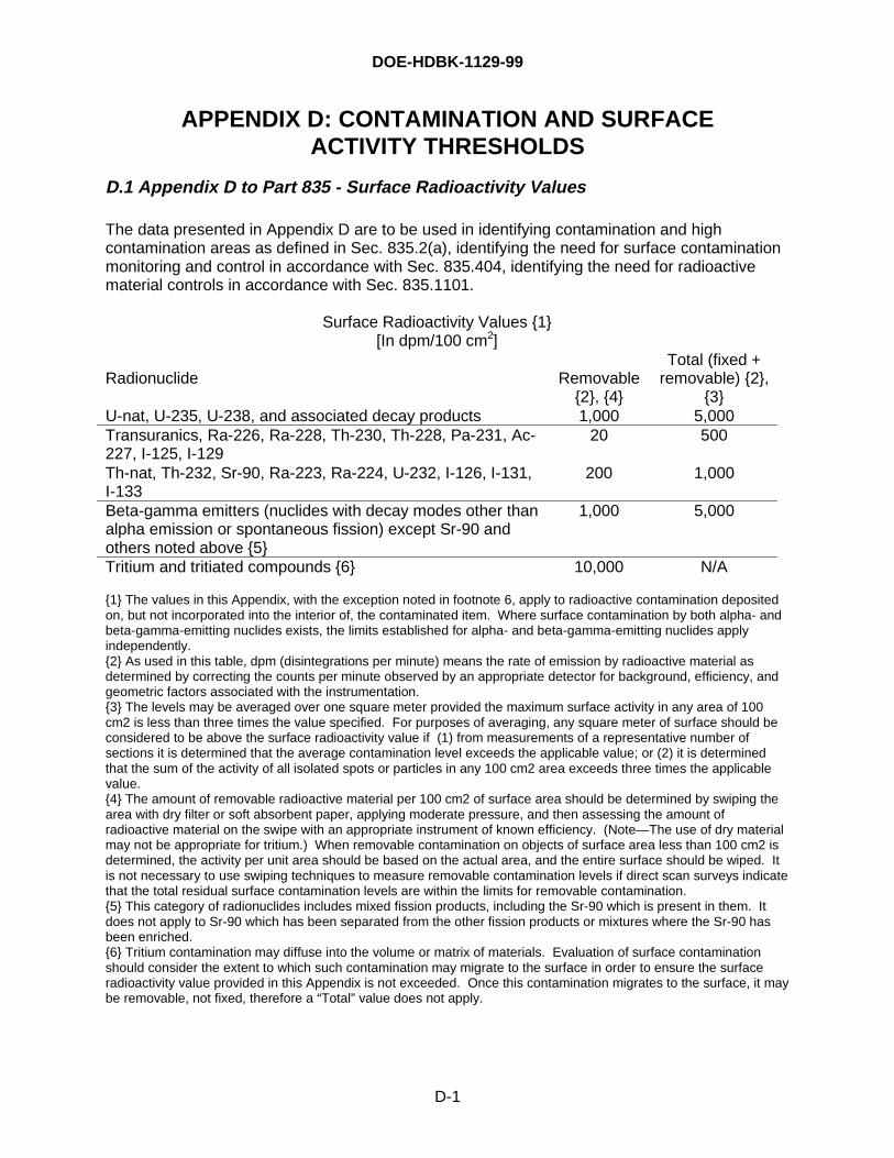
DOE-HDBK-1129-99
D-1
APPENDIX D: CONTAMINATION AND SURFACEACTIVITY THRESHOLDS
D.1 Appendix D to Part 835 - Surface Radioactivity Values
The data presented in Appendix D are to be used in identifying contamination and highcontamination areas as defined in Sec. 835.2(a), identifying the need for surface contaminationmonitoring and control in accordance with Sec. 835.404, identifying the need for radioactivematerial controls in accordance with Sec. 835.1101.
Surface Radioactivity Values {1}[In dpm/100 cm2]
Radionuclide Removable{2}, {4}
Total (fixed +removable) {2},
{3}U-nat, U-235, U-238, and associated decay products 1,000 5,000Transuranics, Ra-226, Ra-228, Th-230, Th-228, Pa-231, Ac-227, I-125, I-129
20 500
Th-nat, Th-232, Sr-90, Ra-223, Ra-224, U-232, I-126, I-131,I-133
200 1,000
Beta-gamma emitters (nuclides with decay modes other thanalpha emission or spontaneous fission) except Sr-90 andothers noted above {5}
1,000 5,000
Tritium and tritiated compounds {6} 10,000 N/A
{1} The values in this Appendix, with the exception noted in footnote 6, apply to radioactive contamination depositedon, but not incorporated into the interior of, the contaminated item. Where surface contamination by both alpha- andbeta-gamma-emitting nuclides exists, the limits established for alpha- and beta-gamma-emitting nuclides applyindependently.{2} As used in this table, dpm (disintegrations per minute) means the rate of emission by radioactive material asdetermined by correcting the counts per minute observed by an appropriate detector for background, efficiency, andgeometric factors associated with the instrumentation.{3} The levels may be averaged over one square meter provided the maximum surface activity in any area of 100cm2 is less than three times the value specified. For purposes of averaging, any square meter of surface should beconsidered to be above the surface radioactivity value if (1) from measurements of a representative number ofsections it is determined that the average contamination level exceeds the applicable value; or (2) it is determinedthat the sum of the activity of all isolated spots or particles in any 100 cm2 area exceeds three times the applicablevalue.{4} The amount of removable radioactive material per 100 cm2 of surface area should be determined by swiping thearea with dry filter or soft absorbent paper, applying moderate pressure, and then assessing the amount ofradioactive material on the swipe with an appropriate instrument of known efficiency. (Note—The use of dry materialmay not be appropriate for tritium.) When removable contamination on objects of surface area less than 100 cm2 isdetermined, the activity per unit area should be based on the actual area, and the entire surface should be wiped. Itis not necessary to use swiping techniques to measure removable contamination levels if direct scan surveys indicatethat the total residual surface contamination levels are within the limits for removable contamination.{5} This category of radionuclides includes mixed fission products, including the Sr-90 which is present in them. Itdoes not apply to Sr-90 which has been separated from the other fission products or mixtures where the Sr-90 hasbeen enriched.{6} Tritium contamination may diffuse into the volume or matrix of materials. Evaluation of surface contaminationshould consider the extent to which such contamination may migrate to the surface in order to ensure the surfaceradioactivity value provided in this Appendix is not exceeded. Once this contamination migrates to the surface, it maybe removable, not fixed, therefore a “Total” value does not apply.
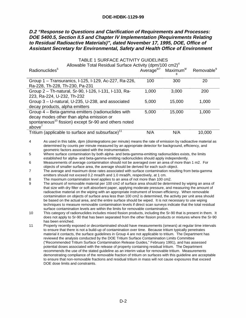
DOE-HDBK-1129-99
D-2
D.2 “Response to Questions and Clarification of Requirements and Processes:DOE 5400.5, Section II.5 and Chapter IV Implementation (Requirements Relatingto Residual Radioactive Materials)”, dated November 17, 1995, DOE, Office ofAssistant Secretary for Environmental, Safety and Health Office of Environment
TABLE 1 SURFACE ACTIVITY GUIDELINESAllowable Total Residual Surface Activity (dpm/100 cm2)4
Radionuclides5 Average6/7 Maximum9/
8Removable9
Group 1 – Transuranics, I-125, I-129, Ac-227, Ra-226,Ra-228, Th-228, Th-230, Pa-231
100 300 20
Group 2 – Th-natural, Sr-90, I-126, I-131, I-133, Ra-223, Ra-224, U-232, Th-232
1,000 3,000 200
Group 3 – U-natural, U-235, U-238, and associateddecay products, alpha emitters
5,000 15,000 1,000
Group 4 – Beta-gamma emitters (radionuclides withdecay modes other than alpha emission orspontaneous10 fission) except Sr-90 and others notedabove7
5,000 15,000 1,000
Tritium (applicable to surface and subsurface)11 N/A N/A 10,000
4 As used in this table, dpm (disintegrations per minute) means the rate of emission by radioactive material asdetermined by counts per minute measured by an appropriate detector for background, efficiency, andgeometric factors associated with the instrumentation.
5 Where surface contamination by both alpha- and beta-gamma-emitting radionuclides exists, the limitsestablished for alpha- and beta-gamma-emitting radionuclides should apply independently.
6 Measurements of average contamination should not be averaged over an area of more than 1 m2. Forobjects of smaller surface area, the average should be derived for each such object.
7 The average and maximum dose rates associated with surface contamination resulting from beta-gammaemitters should not exceed 0.2 mrad/h and 1.0 mrad/h, respectively, at 1 cm.
8 The maximum contamination level applies to an area of not more than 100 cm2.9 The amount of removable material per 100 cm2 of surface area should be determined by wiping an area of
that size with dry filter or soft absorbent paper, applying moderate pressure, and measuring the amount ofradioactive material on the wiping with an appropriate instrument of known efficiency. When removablecontamination on objects of surface area less than 100 cm2 is determined, the activity per unit area shouldbe based on the actual area, and the entire surface should be wiped. It is not necessary to use wipingtechniques to measure removable contamination levels if direct scan surveys indicate that the total residualsurface contamination levels are within the limits for removable contamination.
10 This category of radionuclides includes mixed fission products, including the Sr-90 that is present in them. Itdoes not apply to Sr-90 that has been separated from the other fission products or mixtures where the Sr-90has been enriched.
11 Property recently exposed or decontaminated should have measurements (smears) at regular time intervalsto ensure that there is not a build-up of contamination over time. Because tritium typically penetratesmaterial it contacts, the surface guidelines in Group 4 are not applicable to tritium. The Department hasreviewed the analysis conducted by the DOE Tritium Surface Contamination Limits Committee(“Recommended Tritium Surface Contamination Release Guides,” February 1991), and has assessedpotential doses associated with the release of property containing residual tritium. The Departmentrecommends the use of the stated guideline as an interim value for removable tritium. Measurementsdemonstrating compliance of the removable fraction of tritium on surfaces with this guideline are acceptableto ensure that non-removable fractions and residual tritium in mass will not cause exposures that exceedDOE dose limits and constraints.
DOE-HDBK-1129-99
E-1
APPENDIX E: RESOURCES USED IN WRITING THISHANDBOOK
1. U.S. Environmental Protection Agency’s Federal Guidance Report No. 11, Table 1 “LimitingValues of Radionuclide Intake and Air Concentration and Dose Conversion Factors forInhalation, Submersion, and Ingestion,” September 1988.
2. Villagran, J.E., Whillians, D.W., “Radiation Dose to Lung Cell Populations Resulting from theInhalation of Titanium Tritide Particles,” presented at the Health Physics Society Meeting inNew Orleans, 1984.
3. McConville, G.T., Wood, C.M., Calculation of Tritium Dose from Insoluble Particulates,Fusion Technology, Vol. 28, pp. 905-909, October 1995.
4. De Ras, E.M.M., Vaane, J.P., Van Suetendael, W., Investigation of the Nature ofContamination Caused by Tritium Targets Used for Neutron Production, CEC-JRC, CentralBureau for Nuclear Measurements, Geel, Belgium, published in 5th International Congress ofthe International Radiation Protection Association (IRPA) Volume 1, held in Jerusalem,Israel, March 1980.
5. International Commission of Radiological Protection, Publication 71, Age-dependent Dosesto Members of the Public from Intake of Radionuclides: Part 4 – Inhalation DoseCoefficients, Oxford, Pergamon Press; 1995.
6. Heung, L.K., Titanium for Long Term Tritium Storage, WSRC-TR-94-0596, December 1994.
7. Drolet, T.S., Wong, K.Y., and Dinner, P.J., Canadian Experience with Tritium – The Basis ofa New Fusion Project, Nuclear Technology/Fusion, Vol. 5, January 1984.
8. Kherani, N.P., and Shmayda, W.T., Bulk Getters for Tritium Storage, Ontario HydroResearch Division.
9. Shmayda, W.T. and Kherani, N.P., On the Unloading of Titanium Getter Beds, OntarioHydro Research Division, Report No. 85-118-K, October 2, 1985.
10. Kherani, N.P., and Shmayda, W.T., Titanium Sponge for Immobilization Tritium Containers,Ontario Hydro Research Division, Report No. M85-120-K, December 19, 1985.
11. Noga, J.O., Investigations of Titanium and Zirconium Hydrides to Determine Suitability ofRecoverable Tritium Immobilization for the Pickering Tritium Removal System, OntarioHydro Research Division, Report No. 81-368-K, November 12, 1981.
12. Guidelines for Canadian Drinking Water Quality, 6th Edition, 1996, Health Canada Report,96-EHD-196.
13. Preamble of the First Third Land Disposal Restrictions Final Rule, 53 FR 31149, August 17,1988.
14. Memorandum, Environmental Protection Agency, Marcia E. Williams and Christina Kaneento Robert L. Duprey, “Applicability of Bevill Amendment to the American Natural Gas CoalGasification Facility,” September 1987.
DOE-HDBK-1129-99
E-2
15. Letter, Marcia E. Williams, EPA, to G. N. Weinreich, ANG Coal Gasification Co., June 16,1986.
16. Memorandum, Environmental Protection Agency, John H. Skinner to Harry Seraydarian,“Clarification of Mining Waste Exclusion,” May 16, 1985.
17. RCRA Superfund Hotline Report, February 1985.
18. DOE-STD-1027-92 Change Notice 1, “Hazard Categorization and Accident AnalysisTechniques for Compliance with DOE Order 5480.23, ‘Nuclear Safety Analysis Reports,’”September 1997.
19. DOE Limited Standard, DOE-EM-STD-5502-94, “Hazard Baseline Documentation,” August1994.
20. “Implementation Guidance for Authorization Basis,” DOE Office of Defense Programs,Revision 1, August 21, 1995.
21. William R. Wall, LLNL, “Estimating the Maximum Dose Due to a Tritium Release,” WhitePaper, November 1997.
22. Memorandum, Department of Energy, Ohio Field Office, Nat Brown to Elizabeth L. Osheim,“Mound Commercial Business Employees – ‘Public’ Versus ‘Co-Located,’” April 7, 1997.
23. P. D. Gildea, H. G. Birnbaum, and W. R. Wall, “Modification and Testing of the SandiaLaboratories, Livermore Tritium Decontamination Systems,” Proceedings of the 15th DOENuclear Air Cleaning Conference, CONF-788019 Vol. I, August 1978.
24. “Tritium Facility Decommissioning, Pioneering Success at the Savannah River Plant,”DOE/SR-5000-510, October 1997
25. John Gill, Babcock & Wilcox of Ohio, Personal Communication to Bill Weaver, July 1998
26. “Fire Risk Implications in Safety Analysis Reports,” White Paper by D. A. Coutts, M. E.Bowman, C. E. Shogren, and M.J. Hitchler, WSMS, to be issued in February 1999
27. DOE Memorandum, from S. Blush, NS-1, to R. Claytor, DP-1 and P. Ziemer, EH-1, RTFAssessment of Fire Barriers, October 28, 1991
28. DOE Memorandum from Tom Rollow, Acting Director, Office of Nuclear Safety, to NealGoldenberg, NE 70, “NS Response to Request for Deviation for Replacement TritiumFacility (RTF),” May 7, 1993
29. K.J. Hofstetter, et al., “Field Deployable Tritium Analysis System for Ground and SurfaceWater Measurements,” accepted for publication in the Journal of Radioanalytical andNuclear Chemistry.
30. N.P. Kherani, W.T. Shmayda, “Ionization Surface Activity Monitor for Tritium,” FusionTechnology 28(3) (1995) 893.
31. W.T. Shmayda, N.P. Kherani, D. Stodilka, “Evaluation of the Tritium Surface ActivityMonitor,” Proceedings of the Symposium on Fusion Technology, Lisbon, 1996.
DOE-HDBK-1129-99
E-3
32. N.P. Kherani, W.T. Shmayda, “Monitor for Measuring the Radioactivity of a Surface,” USand European patents pending.
33. SRS H1616 Hydride Transport Vessel Qualification Report (U), WSRC-RP-92-1161,Revision 2, 1995.
34. “Response to Questions and Clarification of Requirements and Processes: DOE 5400.5,Section II.5 and Chapter IV Implementation (Requirements Relating to Residual RadioactiveMaterial),” DOE Office of the Assistant Secretary for Environmental Safety and Health,Office of Environment, November 17, 1995.
35. Robert H. Drake, “Recovery of Tritium from Tritiated Waste Water Cost EffectivenessAnalysis,” LA-UR-97-3767, Los Alamos National Laboratory, June 1996.
36. Scott Willms, “Deploying the Palladium Membrane Reactor for Concentrated Tritiated WaterProcessing,” Technology Development Initiative, Los Alamos National Laboratory, May 5,1997.
37. W. Kelly, DOE Defense Programs, Personal Communication to Bill Weaver, 1997.
38. Jack Metzler, DOE Defense Programs Personal Communication to Bill Weaver, 1997.
39. Robert Machacek, Ontario Hydro, Personal Communication to Bill Weaver, 1997.

DOE-HDBK-1129-99
E-4
This page is intentionally blank.
DOE-HDBK-1129-99
F-1
APPENDIX F: CHARTER OF THE TRITIUM FOCUS GROUP
GOALS – The goals of the TFG are to promote continuous, cost-effective improvementin safety and operations, and enhance the proactive management of the spectrum ofDepartment of Energy (DOE) facilities handling tritium.
OBJECTIVES – The objectives of the TFG are to:
1. Provide a forum which fosters exchange of information and ideas,especially conduct of operations, lessons-learned, and root causedeterminations;
2. Serve as a DOE-wide resource for tritium operations management withauthority to conduct special studies, develop and propose guidelines andbest practices for operations, and facilitate peer review of relevantdocumentation;
3. Develop consistency in implementation of as-low-as-reasonably-achievable (ALARA) programs and the assessment and reporting of risksand hazards;
4. Promote implementation of a staged and graded program of upgrades tofacilities and procedures;
5. Promote sharing and application of state-of-the-art design and engineeringtechnology and operating techniques in DOE; and
6. Develop consistency in terminology utilized in DOE tritium operations.
ORGANIZATION – A Tritium Operations Management Focus Group (TOMFG),consisting of the TFG Chairperson, Co-Chairperson, and Headquarters ProgramManagers and Facilities Management Division Directors, will review and approve TFGactivities, including submittal of the initial Charter, and any revisions thereto, to theProgram Secretarial Officers for final approval. The TOMFG shall serve as the principalHeadquarters liaison and management element to facilitate successful operation of theTFG. The TFG membership will consist of the TOMFG, plus a DOE and contractormember and an alternate for each, to be designated by the respective management ateach site responsible for the processing and handling of tritium. The members will befrom organizational levels having cognizance over tritium operational aspects at theirrespective facilities, including processing, hazards, and improvement programs. TheTFG will be chaired by a DOE Field Office representative and co-chaired by a contractorrepresentative from the same site, as designated by the TOMFG in coordination withthe appropriate Field Office Manager. The chairperson and co-chairperson will serve a2-year term.
DOE-HDBK-1129-99
F-2
ADMINISTRATION – The TFG activities will receive sufficient management priority interms of resource commitment to achieve the stated goals and objectives. Priorities willbe established jointly between the respective DOE Program Managers and FacilityManagement Division Directors at Headquarters, and the DOE Field Office managers.The TFG shall look to the TOMFG to resolve any conflicts in site priorities and toachieve consensus guidelines and best practices proposed for approval by the DOE lineorganization.
MEETINGS – The TFG will meet on a periodic basis of at least two times per year.Meeting topics and agenda will be jointly developed by group members, and approvedand issued by the Chairperson. Meeting locations will be rotated among the respectivesites. DOE oversight organizations will be invited, as appropriate. As a minimum, theminutes of each meeting will be written and distributed to members within 10 days. TheTOMFG will meet, as necessary, to assure timely action on proposals and continuity ofthe TFG efforts.
TRITIUM FOCUS SUBGROUPS (TFS) – The TFG will initiate formation of TFSs, asnecessary, to recommend solutions to problems or concerns that may arise within thetritium complex. This may include the hosting of workshops to address issues such asimplementation of specific XXX orders. Conclusions of the TFSs will be documentedand distributed to TFG members. Proposals from the TFG will be provided through theTOMFG to appropriate DOE line management for approval.
TECHNICAL EXCHANGE – The TFG will encourage exchange of related technicalinformation via meetings, conferences, and symposia.
DELIVERABLES – Initial deliverables will be timely communication and sharing ofoperational experiences among the facilities, meeting minutes, and proposals. Otherdeliverables will be developed in accordance with associate milestone schedules andIFS activity.
CHARTER REVIEW – The Charter will be reviewed annually and revised, asnecessary.
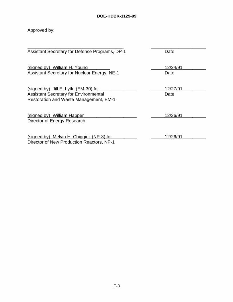
DOE-HDBK-1129-99
F-3
Approved by:
Assistant Secretary for Defense Programs, DP-1 Date
(signed by) William H. Young 12/24/91 Assistant Secretary for Nuclear Energy, NE-1 Date
(signed by) Jill E. Lytle (EM-30) for 12/27/91 Assistant Secretary for Environmental DateRestoration and Waste Management, EM-1
(signed by) William Happer 12/26/91 Director of Energy Research
(signed by) Melvin H. Chiggioji (NP-3) for 12/26/91 Director of New Production Reactors, NP-1

DOE-HDBK-1129-99
F-4
This page is intentionally blank.
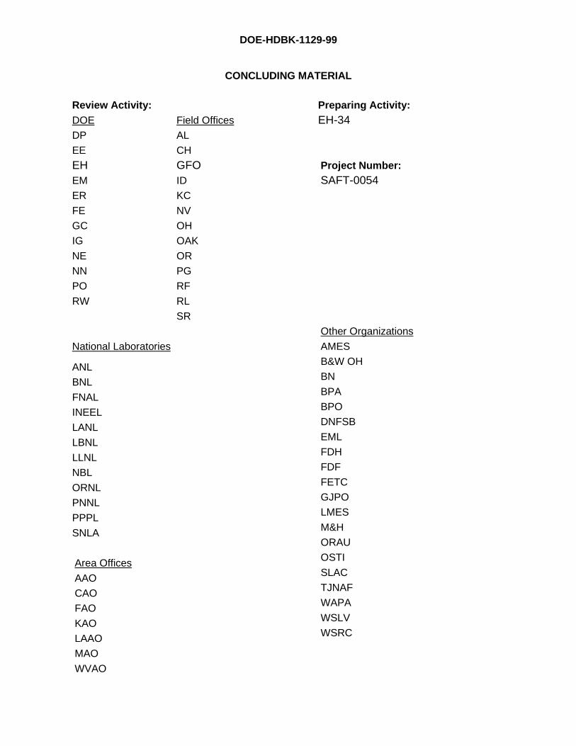
DOE-HDBK-1129-99
CONCLUDING MATERIAL
Review Activity:DOE Field Offices
DP AL
EE CH
EH GFOEM ID
ER KC
FE NV
GC OH
IG OAK
NE OR
NN PG
PO RF
RW RL
SR
National Laboratories
ANL
BNL
FNAL
INEEL
LANL
LBNL
LLNL
NBL
ORNL
PNNL
PPPL
SNLA
Area Offices
AAO
CAO
FAO
KAO
LAAO
MAO
WVAO
Preparing Activity:EH-34
Project Number:SAFT-0054
Other Organizations
AMES
B&W OH
BN
BPA
BPO
DNFSB
EML
FDH
FDF
FETC
GJPO
LMES
M&H
ORAU
OSTI
SLAC
TJNAF
WAPA
WSLV
WSRC