DOD-STD-1866 - MIL-STD-188everyspec.com/DoD/DoD-STD/download.php?spec=DOD-STD-1866_N… ·...
20
DOD-STD-1866 NOTICE 1 19 !&Y 1988 MILITARY STANDARD SOLDERING PROCESS GENERAL i- .- (NON-ELECTRICAL) TO ALL HOLDERS OF DOD-STD-1866: 1. THE FOLLOWING PAGES OF DOD-STD-1866 HAVE BEEN PAGE LISTED: NEW PAGE DATE SUPERSEDED PAGE v 21 August 1981 v vi 19 tiy 1988 vi 3 19 &y 1988 3 4 19 May 1988 4 11 19 tiy 1988 11 12 21 August 1981 12 13 21 August 1981 13 14 19 tiy 1988 14 17 19 hy 1988 17 18 21 August 1981 18 19 19 by !9RR 19 19a 19 t%ly1988 — 20 21 August 1981 20 21 19 tiy 1988 21 24 21 August 1981 24 24a 19 hy 1988 — 2. RET.41!i THIS NOTICE AND INSERT BEFORE TABLE OF 3. Holders of DOD_STD-1866 will verify that page REVISED AND SUPERSEDE THE DATE Reprinted without change 21 bgust 1981 21 August 1981 21 August 1981 21 August 1981 Reprinted without change Reprinted without change 21 August 1981 21 August 1981 Reprinted without change 21 August 1981 —. Reprinted without change 21 August 1981 Reprinted without change --— CON’ENTS. changes and additions indicated above have been entered. This notice page will be retained as a check sheet. This issuance, together with appended pages, Is a separate publication. Each notice is to be retained by stocking points until the military standard is completely revised or canceled. Custodians: Preparing activity: Army - AT Artny- AT tir Force - 99 (Project SOLD-0026) Review activities: Army - MI, AR, AV Navy - MC User activities: Army - ME Navy - 0s AMSC N/A AREA SOLD DISTRIBUTION STATEMENT A. Approved for public release; distribution is unllmited. Downloaded from http://www.everyspec.com
Transcript of DOD-STD-1866 - MIL-STD-188everyspec.com/DoD/DoD-STD/download.php?spec=DOD-STD-1866_N… ·...
DOD-STD-1866NOTICE 119 !&Y 1988
MILITARY STANDARD
SOLDERING PROCESS GENERAL
i-
.-
(NON-ELECTRICAL)
TO ALL HOLDERS OF DOD-STD-1866:
1. THE FOLLOWING PAGES OF DOD-STD-1866 HAVE BEEN
PAGE LISTED:
NEW PAGE DATE SUPERSEDED PAGE
v 21 August 1981 vvi 19 tiy 1988 vi3 19 &y 1988 34 19 May 1988 411 19 tiy 1988 1112 21 August 1981 1213 21 August 1981 1314 19 tiy 1988 1417 19 hy 1988 1718 21 August 1981 1819 19 by !9RR 19
19a 19 t%ly1988 —
20 21 August 1981 2021 19 tiy 1988 2124 21 August 1981 2424a 19 hy 1988 —
2. RET.41!iTHIS NOTICE AND INSERT BEFORE TABLE OF
3. Holders of DOD_STD-1866 will verify that page
REVISED AND SUPERSEDE THE
DATE
Reprinted without change21 bgust 198121 August 198121 August 198121 August 1981
Reprinted without changeReprinted without change
21 August 198121 August 1981
Reprinted without change21 August 1981
—.
Reprinted without change21 August 1981
Reprinted without change--—
CON’ENTS.
changes and additionsindicated above have been entered. This notice page will be retained as acheck sheet. This issuance, together with appended pages, Is a separatepublication. Each notice is to be retained by stocking points until the
military standard is completely revised or canceled.
Custodians: Preparing activity:
Army - AT Artny- AT
tir Force - 99(Project SOLD-0026)
Review activities:Army - MI, AR, AVNavy - MC
User activities:Army - MENavy - 0s
AMSC N/A AREA SOLD
DISTRIBUTION STATEMENT A. Approved for public release; distribution is unllmited.
Downloaded from http://www.everyspec.com

Downloaded from http://www.everyspec.com
.DOD-STD-1866
CONTENTS - Continued
,=
Paragraph 5.4.25.4.2.15.4*35.4.3.15.4.45.4.4.15.4.55.4.5.15.4.65.4.6.15.4.75.4.7,15.4.85.4.8.15*4.95.4.9.15.55*5.15.5.2
5.5.35.6<Al-.”.-5.6.25.6.35.6.45.6.55.6.65.6.75.6.85.6.95.6.105.6.115.6.125.6.135.6.145.6.155.6.165.6.175.6.17.15.6.17.25.75.7.15.7.2
Flame Soldering.............................Procedure...................................Dip Soldering.........● ......● ● ...● .● ....● ..Procedure...................................Resistance Method...........................Procedure...................................Oven or Furnace Method......................Procedure...................................Induction Method............................Procedure...................................Ultrasonic Method..● ● ..● ● ..............● ● .● .Procedure...................................Spray Gun Method.......... ..................Procedure...................................Wave Method.................................Procedure...................................Post Soldering Treatment....................Cooling.....● **● *...● .......● ● ....● .........Flux Removal................................
Passivation of Stainless Steel Assemblies...Quality Considerations......................IJfi-km.nch<n. . ...”-— ----- r - - - : . : : * = =:- -- - - --- -.. ● ● .- ● ● “ ● ● “*
Appearance..................................Flow and Wetting Action.....................Line od Demarcation.........................Contour.....................................Porosity....................................B~i~te,s.,,,,...........,...................
Residual Flux...............................Excess Solder...............................Unmelted Solder.............................Penetration..............● .................Cold Solder.................................Disturbed Solder............................Aggregate Area..............................Extent of Single Defect.....................Resoldering.................................
Humidity Test...............................Test Cabinet................................Procedure...................................Application Data............................Copper and Copper Alloys................... .Steels......................................
9s
1111
1212121212131313131313141414141414151515151515161616161616161616161717171717171718
(
“.-V
Reprinted without change.
Downloaded from http://www.everyspec.com
.
Paragraph 5.7.35.7.45.7.55.7.65.7.75.7.85.7.95.7.9.15.7.9.25.7.10
6.6.1
Tabie 1.II.111.
Iv.v, ‘
VI.
DOD-STD-1866
CONTENTS - Continued
Nickel and Nickel Alloys....................Lead and Lead Alloys........................Aluminum and Aluminum Alloys................Magnesium and Magnesium Alloys..............Cast Iron...................................Cadmium-silver and Cadmium-zinc Alloys......Fluxes......................................Non Corrosive Flux..........................Chemical and Reaction Fluxes................For Electrical and Electronic Soldering.....
NOTES . . . . . . ● . . . . . . . . . . . ● . . . . . . . . . . . . . . ● .**. . ●
Subject term (key word) listing.............
TABLES
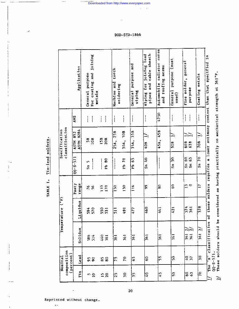
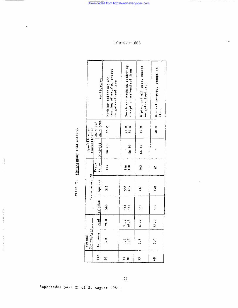
Tin-lead Solders.............................Tin-antimony Lead Solders....................Tin-antimony, Tin-silver and Lead-silverSolders.....................................
Tin-lead-Zinc-aluminum Solders...........=.”.Fusable Alloy Solders........................IridiumSolders...............................
18181818181819191919
19a19a
2021
22
232424
vi
Supersedes page vi of 21 AUgUSt 1981.
Downloaded from http://www.everyspec.com
I
DOD-STD-1866
2. REFERENCED DOCUMENTS
2.1 Government documents.
2.1.1 Specifications and standards. Unless otherwise specified, the
following specifications and standards of the issue listed in that issuethe Department of Defense Index of Specifications and Standards (DODISS)specified in the solicitation form a part of this standard to the extentspecified herein.
SPECIFICATIONSFEDERAL
A-A-50971A-A-51128V-S-564W-S-570QQ-S-571
MILITARY
MIL-M-3800
MIL-S-12204UT7~-,AM—F- i2784MIL-F-14256MIL-S-45743
MIL-S-46844MIL-S-46860
STANDARDSFEDEML
FED-STD-151
MILITARY
MIL-STD-105
MIL-STD-454
MIL-sTD-8io
of
- Soldering Iron, Non-Electric (Coppers).
Torch, Kit Soldering (Propane Gas).- Soldering Gun.- Soldering Lron, Electric.- Solder; Tin-Alloy, Tin-Lead Alloy and LeadAlloy ●
- Metallizing Outfits (Wire-Gas), Guns and&cessories.
- Solder, Lead-Tin Alloy.r~....c~I~~Amfi {<te=r~~e Compnund IC-3)..*-a* -“-”----~ ,-
- FIux, Soldering, Liquid (ROsin-hse).Soldering, Manual Type, High ReliabilityElectrical and Electronic Equipment.Solder Bath, Soldering of Printed Wiring.Soldering of Metal Ribbon Lead Materials toSolder Coate6 Terainals, Process.
- Metals: Test Methods.
Sampling Procedures and Tables forInspection by Attributes.Standard General Requirements forElectronic Equipment.Environmental Test Methods and EngineeringGuidelines.
I L.
3
Supersedes page 3 of 21 August 1981.
Downloaded from http://www.everyspec.com
DOD-STD-1866
(Copies of specifications and standards, required by contractors inconnection with specific acquisition functions should be obtained from the
contracting activity or as directed by the contracting officer.)
2.2 Other publications. The following documents form a part of thisstandard to the extent sDecified herein. Unless otherwise specified, theissues of the documents which are DOD adopted shall be those-listed in theissue of the DODISS specified in the solicitation. The issues of documentswhich have not been adopted shall be those in effect on the date of the citedDODISS.
SOCIETY OF AUTOMOTIVE ENGINEERS (SAE)
AMS-4750 - Solder - Tin-Lead 45 Sri-55Pb.AM-4755 - Solder - Lead-Silver 94 Pb-5.5 Ag..~ys_475~ - Solder - 97.5 Pb-1.5 .Ag-lSn.
(Application for copies should be addressed to the Sociecy of AutomotiveEngineers, 400 Commonwealth Drive, Warrendale, PA 15096.)
AMERICAN SOCIETY FOR TESTING AND MATERIALS (MYIIl)
ASTM B32 - Solder Metal.ASTM B284 - Rosin Flux Core Solder.
(Application for copies should be addressed to American Society forTesting and Materials, 1916 ~ce Street, Philadelphia, PA, 19103.)
(Nongovernment standards are generally available for reference fromlibraries. They are also distributed among nongovernment standards bodiesand using Federal agencies.)
2.3 Order of precede~ce. In the event of a conflict between the texz ofthis standard and the references cited herein, the text of this standardshall take precedence.
.
4
Supersedes page 4 of 21 August 1981.
Downloaded from http://www.everyspec.com
DOD-STD-1866
5.4 Soldering methods.
5.4.1 Type I - Conduction soldering. Conduction soldering (solderingiron) shall be performed with soldering irons having copper bits which may beheated electrically, or by oil, coke or gas flame. Regardless of the type ofiron used, the coppper bit shall store and transmit heat from the source tothe part being soldered, shall store and convey molten solder and shallwithdrsw surplus molten solder as required. Internally firedgas-flame-heated soldering irons may be used where electric power is notreadily available, or where soldering is done automatically at high rates ofspeed. Electrically heated irons, often more convenient than gas-heatedirons, should be used in ~nual hfgh-speed repetitive operations, where lightweight and ease of ~nipulation are desirable and open flames areobjectionable. Selection of iron shall be such as to perform the necessarysolderi~g operations with the greatest efficiency. For soldering process,electzic soldering ii~ns? confotin3 to W-S-570, soldering guns, conformingto $7-S-564,or non-.leccric soldering irons, conforming to A-A-50971 may beused.
5.4.1.1 Procedure. The areas to be joined shall be heated above theliquidua temperature of the solder. TO deliver maximum heat to the part, thecopper bit of the soldering iron shall be applied at the correct angle. Theflat side of the bit shall be applie~ to secure the maximum area of contact.Excessive time ~d temperature aha~l be avoided to prevent unreliable joints
and damage to parts. If required, ther~l shunts (heat sinks) shall be usedfor protection of parts. The parts to be joined shall be held together insuch manner that parts shall not move in relation to one another during thesoldering operation. The solder shall be applied to the joint and not to thesoldering iron. The joint shall not be disturbed until the solder hascompletely solidified.
5.4.2 Type 11 - flame solderfn~. The selection of a gas or oil burning
torch for soldering shall be controlled by the size, mass, and configurationof the assembly to-be soldered. Time for performing the operation will alsobe a factor in equipment selection. Depending upon the temperature andamount of heat required, fuels such as acetylene, propane, butane, andnatural gas, may be used in open air, or with compressed air or oxygen.Portability till be another factor in selection of a torch. For field work,a soldering torch kit, A-A-51128, using propane gas, may be used for torchsoldering.
5.4.2.I Procedure. Parts shall be preheated with a neutral or slightlyreducing flameto bring the entire joint uniformly to the iiquidustemperature of the solder’,but no higher than necessary to provide asatisfactory joint. Localized overheating shall be avoided. The solder maybe introduced at one edge of the interstice, or in a groove provided for one
of the mating surfaces, and shall flow by capillary action to fill theinterstice.
11
Supersedes page 11 Of 21 August 1981.
.
...
Downloaded from http://www.everyspec.com
DOD-STD-1866
5.4.3 Type 111 - Dip solderin~ Mp soldering shall be performed by -immersing the assembled joint with preplaced solder metal in a bath of moltenflux, by immersing the assembled joint into a flux solution and then into abath of molten solder, or by dipping the parts into a bath of molten solderalloy covered with a layer of flux+ Pots for the bath, either electricallyheated or gas heated units, shall be of such capacity and construction as toallow production without appreciably lowering the temperature of the bath.The flux shall be of a type which has a stable flowability within thesoldering temperature range, and processes satisfactory fluxing properties.The flux bath shall be free of metallic impurities.
5.4.3.1 Procedure. When required or specified (see 1.4), assembliesshall be preheated in a suitable furnace and atmosphere to a temperature of25 to 100”F below the solldus temperature of the soldering alloy, Generallywhen a molten bath of solder is employed, no preheating is required. Theassembly, together with jigs or fixtures, when used immediately upo~ removalfrom the preheat furnace, shall be dipped into the molten bath at a uni$onrate so that the position of the prepared solder metal is not disturbed.Soldering times are dependent upon the shape and cross section of theassembly. Soldering is complete when the solder metal haa flowed evenly intothe joints. At this point, the assembly shall be removed slowly from thebath at a rate that will not cause loss of the molten solder metal. The
composition and quantity of solder flux or molten solder shall be adjustedperiodically. The operating temperature of the molten flux bath shall notexceed the liquidus temperature of the specified soldering alloy by more than20”F.
5.4.4 Type IV - Resistance solderin~. The transformer, electrode, and -
voltage/amperage controls shall be of sufficient size and capacity to provide
adequate heat over an area large enough to permit free flow of the solderalloy over the area to be soldered, wlchout overheating.
5.4.4.1 Procedure. Assembled parts shall then be placed between aground and a moveable electrode, or between two moveable electrodes, and thecurrent passed through the system. Heating of the joint is generated by
contact with the electrodes, and the heat energy evolved is a direct productof the resistance of the work and the current passing through it (Q = I R).Resistance soldering electrode bit generally cannot be turned; therefore,flux and solder must be in proper position before heating. Heating still be
discontinued as soon as the solder metal has flowed and formed fillets.
5.4.5 Type V - Oven and furnace solderin~ Ovens and furnaces shall beof suitable design and size to maintain uniforms constant temperature withinthe soldering area. Devices shall control the wwrking temperature within oneand one half percent of the temperature required for the item or items to besoldered. Ovens and furnaces shall be equipped with a means of controllingthe atmosphere within the oven or furnace, as required, to prevent oxidation
of the basis metals.
12
Reprinted without change.
Downloaded from http://www.everyspec.com
I
.
.
I
II
; ...
DOD-STD-1866
5.4.5.1 Procedure. Parts shall be assembled with proper fit inalignment as required with proper clamping fixtures. Flux may be used inaddition to control of oven or furnace atmosphere. Assemblies, cradled andracked, shall be placed in the oven or furnace In such manner that theatmosphere can reach all parts of the soldering assembly readily, and bringthe entire assembly to soldering temperature in the shortest possible time.Parts shall be held in the oven or furnace until the filler metal has meltedand formedassembliesoxidation.or furnaceto prevent
5.4.6design and
the desired bond. After soldering has been accomplished,shall be cooled in protective atmosphere, as required, to preventThe cooling of parts may be accelerated on removal from the ovenby the use of an air blast on the hot parts, caution being takenwarpage.
Type VI - Induction solderin~. Induction coils shall be of suchconstruction as to provide suitable heating of the joint areas.
Coil design must allow for corner effects on rectangular parts, surfaceirregularities which must be in the heat zoue, and for joining of dissimilarmetals, particularly joints composed of both magnetic and non-magneticcomponents.
5.4.6.1 Procedure. The mating surfaces shall be coated with flux,either corrosive or noncorrosive, containing a minimum percentage of solventin order to reduce the amount of volatile matter driven off during heating.Alternately, parts may be enclosed in a suitable atmosphere. The fillermetal shall be placed in position and the joint heated by placing within, ornaar----, a ~tui~~b~~iadl~~~i~nhe~tfng enil.
5.4.7 Type VII - Ultrasonic solderinq. Oscillators for generatingelectrical impulses, magnetostrictive transducers, shall be of such designand construction as to provide suitable cavitation erosion on the surface ofthe metal, permitting molten solder to wet the surface. The ultrasonicvibrations shall be transmitted from the laminated nickel core, which is usedto reduce eddy currents, to the joint. A metal rod of suitable length, whichconnects the transducer to the soldering bit, shall be attached to the coreso that maximum disturbance will result at the free end. The free end of themetal rod, which forms the soldering bit, shall be immersed in a small poolof molten solder that contacts the surface to be soldered. The metal rodshall then be moved across the surface of the base metal or joint so thatultrasonic vibrations break Up the oxide on the surface, exposing theunderlying metal to the wetting action of the molten solder.
5.4.7.1 Procedure. The area to be coated shall be heated to solderingtemperature. A suitable quantity of solder shall then be melted on thesurface to fo~ a molten puddle. The end of the transducer rides over thesurface. Two such solder-coated areas shall then be placed together andheated, until the solder coat melts and forms a bond.
-.
5.4.8 Type VIII - Spray gun solderin~ Spray guns shall be of suitabledesign and construction, so as to permit heating and spraying a continuousfeed solid solder wire. Depending upon gun design, propane, acetylene, ornatural gas with oxygen may be used for heating and spraying. Equipmentshall be similar to that specified in MIL-M-3800.
13
Reprinted without change.
Downloaded from http://www.everyspec.com
DOD-STD-1866
5.4.8.1 Procedure. Parts shall be assembled with proper fit and fixedin alignment as required. Using ordinary metal spraying techniques, the vastmajority of solder is melted by the neutral flame of the gun. The soldershould contact the part in a semi-liquid form. The balance of heat required,to melt the filler metal and bring the entire joint uniformly to the liquidustemperature of the solder for flowing, is to be supplied by the part.
5.4.9 Type IX - Wave solderin%. Wave soldering equipment shall be of a
suitable design and construction to permit an automatic application ofsolder. A continuous stream of solder shall be pumped up into the spout,forming a head of solder through which the work can be passed. The equipmentand materials used shall pump a fresh amount of solder into the solder headat all times, so that dross will not accumulate on the solder surface or comein contact with the work. All flux and flux residues, which are wiped offthe work and normally stay on top of the solder bath, shall be carried downwith the vave into a s?ecial rese>oir, where they shall not come in contactwith any ~uture work. Means shill be provided so that solder which is pumpedout of the bottom of the soitierconcainer is always at the same temperature,and the solder reaching the head has no time ta be cooled down by air draftsand other incidental side effects. The eq=ipmenr shall be such that thetemperature of the solder touching the work shall be uniform and can easilybe controlled and maintained.
5.4.9.1 Procedure. Parts shall be fluxed by suitable applicationmethods such as brushing, rolling, spraying, foaming, dipping or wavefluxing. The work shall then be passed through the equipment so that the
molten solder and oil are pumped together to hit the ~ork simultaneously andprevent rapid oxidation. Oil dispersion shall be smooth and evenlydistributed, by injection where the velocity of the solder is greatest. Itis important that preheating prior to soldering be performed, in order togive the flux enough temperature and time to clean and prepare the surfaces,bec=use of the reduced time of the wave. After wave soldering has beenaccomplished, assemblies musr be adequately post-treated to remove oi.1~whenever used in conduction with this method.
5.5 Post-soldering treataent.
5.5.1 Coolin~. Proper jigging, assembly, or controlled cooling, shall
be empioyed to prevent excessive deformation of the joint, or failure of thejoint, during solidification of the solder. The cooling method may be variedto suit each individual application process.
5.5.2 Flux removal. Immediately after soldering and cooling, flux shall,or shall not, be removed depending upon the degree of corrosiveness. Fluxes
conforming to MIL-F-14256, or those ❑eeting the requirements of type R and RMA
of QQ-S-571, having a rosin base do not generally require removal of theresidue, except If appearance is a prime factor or if the joint areas is to bepainted or otherwise coated. Fluxes conforming to O-F-506, identified ascorrosive because of having a zinc chloride or other corrosive base, leave a.
14
Supersedes page 14 of 21 August 1981.
Downloaded from http://www.everyspec.com
,.
I
(
DOD-STD-1866
5.6.15 Maximum extent of a single defect. When specified, no singleunsoldered area shall exceed 20 percent of the overlap distance of the jointfor aluminum and aluminum alloys, and 15 percent in all other metals.
5.6.16 Resoldering. Resoldering of joints shall be avoided. If for anyreason a satisfactory joint is not initially obtained, the joint shall betaken apart and the parts shall be cleaned. The entire soldering operationshall be repeated so that the quality standards for a resoldered joint shallbe the same as for an original joint. Excessive solder, unmelted solder,lack of penetration, cold solder, and disturbed solder at the joints willrequire only reheating and reflowing of the solder.
5.6.17 Humidity test. When specified (see 1.4), soldered areaa shall betested for completeness of flux removal residue, and corrosive action on thematerials involved, by the humidity test specified in method 507 ofMIL-STD-81O.
5.6.17.1 Test cabinet. The humidity test cabinet shall be lined withsheet metal, with soldered or welded joints, to form a vapor tight chamber.The walls shall be heavily insulated to minimize heat loss and condensation.Temperature and humidity controls shell be automatic, and shall be capable ofmaintaining a dry bulb temperature of 100 ~ 2°F and a wet bulb temperature of98 ~ 2°F’. There shall not be more than 2°F temperature difference between
any two points in the test area at anytime.
5.6.17.2 Procedure. Selected samples shall be placed in the humiditycabinet and exposed to the conditions specified in 5.6.17.1 for a period of72 hours. The samples at the end of the test period shall be examinedvisually, or at a magnification of 4 X, to determine evidence of corrosioncaused by contamination from flux residues or cleaning solutions.
5.7 Triplicationsdata. This standard is intended for use in the controlof nonelectric solaering processes as applied to various metals and alloysin manufacturing. These soldering procedures are used to obtain desiredproperties, such as leak tightness, pressure tightness, and heat conductivitywithin the limits of the reapectfve materials. The solders required for theprocesses detailed in this standard, as structural materials, are weak whencompared to the materials which they are generally used to join. To avoid
depending upon the strength of the solder, -jointsfor sheet metal structuralassemblies should be so designed that surfaces to be soldered by the variousmethods will require the solder only to seal and stiffen the assembly.
5.7.1 Copper and copper alloys. Copper and copper alloys are solderedto form simple economical joints-on equfpment such as heat exchangers,automotive radfators, heating units, finned tubing, water lines, and flexiblemetal hose that requires leak tightness with good beet conductivity.
17
Supersedes page 17 of 21 August 1981.
Downloaded from http://www.everyspec.com
DOD-STD-1866
5.7.2 Steels. Tin plated steel used for air ducts, amplifier frames,condensor and capacitor cans, air filters, and gas meter cases are oftensoldered by the dip soldering process. Terne steel is soldered for assemblyinto air cleaners, gasoline tanks, cans, radiator parts, oil pans, fireextinguisher bodies and burial caskets. Frames, tube covers, and chassis forelectronic equipment, made of galvanized steel, are soldered for assembly.Stainless steel cans, pails and buckets are often soldered after spot weldingor riveting to provide leak tight joints.
5.7.3 Nickel and nickel alloys. Nickel and nickel alloys aresolderable. Application should be used only where resistance to corrosion isnot an important factor. Solder can be used for sealing non-pressurizedwater containers, provided the strength of the joints is supplied by rivets,bolts, staking, lock seams, spot welds or other mechanical means. Thesoldering proiess should be lifited to joints in sheet metal not more than5/8 inch wide. Since the solders are weak compared to the basis nickel andnickel alloys, they should not be used :Dr at:actixg fit:ings tonickel-copper fuel tanks or pressurized water containers. In the eventsoldering ❑ust be used for joining nickel and nickel alloys, only thecorrosive fluxes (see 5.2.2), are recommended.
5.7.4 Lead and lead alloys. Lead pipe with soldered joints, or solderedcopper fittings, are used to convey water underground, or in drainage and.- --venting 9ystems. Leaded sheathed cables for telephone, telegraph, andelectrical power transmission conduit also require solder processing forjoining purposes and waterproofing.
5.7.5 Aluminum and aluminum alloys. Tube fin assemblies and cellularassemblies for aluminum and aluminum alloys are joined by dip soldering.
5.7.6 Magnesium and magnesium alloys. Soldering processes are sometimesused for gealing of electronic components encased in tin, or copper platedmagnesium alloy containers.
5.7.7 Cast iron. Soldering processes may be used for repair of brokenor worn cast iron equipment. Surface cracks and depressions caused byinclusions of metal-old reaction my be filled with solder, if the defectsare superficial and application is not critical. Zinc chloride flux shouldbe applied to the cast iron part prior to soldering application.
5.7.8 Cadmium-silver and cadmium-zinc solders. Cadmium-silver andcadmim-zinc solders have been used for the joining of aluminum and its alloysto itself, or to dissimilar metals, by processes detailed In this standard.These solders are extremely dangerous and are of a highly toxic nature.Overheating the solder during joining can vaporize the cadmium to producehighly dangerous and practically odorless fumes. Precautions must be takenfor proper ventilation which may not be suitable or available, duringsoldering processes. Their use iS not recommended as there are othermaterials,
18
Reprinted without change.
Downloaded from http://www.everyspec.com
.DOD-STD-1866
non-toxic in nature, that are available if soldering of aluminum is required.Also ultrasonic techniques for soldering (see 5.4.7) have been developed, andare being used commercially, which would not require the use of these toxicsolder types.
I
I
I
I
5.7.9 Fluxes.
5.7.9.1 Noncorrosive. Noncorrosive, as used in 5.2.4 to classify fluxes
of this type, is only a relative term. The noncorrosive fluxes are not ascorrosive as the other fluxes listed, namely highly corrosive (see 5.2.2), orintermediate (see 5.2.3), but all fluxes must be corrosive in order to performtheir function. In general, the amount of corrosion resulting from ~onremovalof noncorrosive fluxes may not be harmful to the soldered part or article.
5.7.9.2 Chemical and reaction fluxes. Chemical and reaction fluxes are aspecial group of corrosive fluxes developed for soldering aluminum. Achemical flux is generally composed of an organic fluoborhle (such as borontrifluoride monoethanolamine), a metal fluoborate (such as cadmiumfluoborate), a vehicle (such as methyl alcohol), and a plasticizer (such asstearic acid). Modifiers such as zinc fluoride, zinc chloride, or ammoniumchloride may also be incorporated into the formulation. Reaction fluxesusually are composed of zinc chloride, tin chloride, or combinations of othermetallic halides and ammonium chloride.
5.7.10 For electrical and electronic solderinq. This standard does notcover electrical and electronic soldering requirements, and applies tomechanical soldering only. For soldering of electrical and electronicconnections, Requirement 5 of MIL-STD-454, MIL-S-45743, MIL-S-46844 orMIL-S-46860 should be used.
19
Supersedes page 19 of 21 August 1981.
Downloaded from http://www.everyspec.com
DOD-STD-1866
6. NOTES
6.1 Subiect term (key word) listing.
General Process of Soldering
Non-Electrical SolderingSolderingSoldering, Non-Electrical
.-
19a
Downloaded from http://www.everyspec.com
I
DDD-STD-1866
~
I
4
a I
II IIIII I
III II I 1IIII // I I
III
I
I
—
=!=1 :1-
—
n0
Da.
m cm wQGCC cc
filn -- Lr t-.4 .-
I
—
—
-0Taa.
f+il
—
Int-l
I.—
Reprinted without change.....
Downloaded from http://www.everyspec.com
.
.
Supersedes page 21
I
I
TOm In-Y- C--
1
I
21
21 August
I
Downloaded from http://www.everyspec.com
.—
.
I
II
EOD-sTD-1866
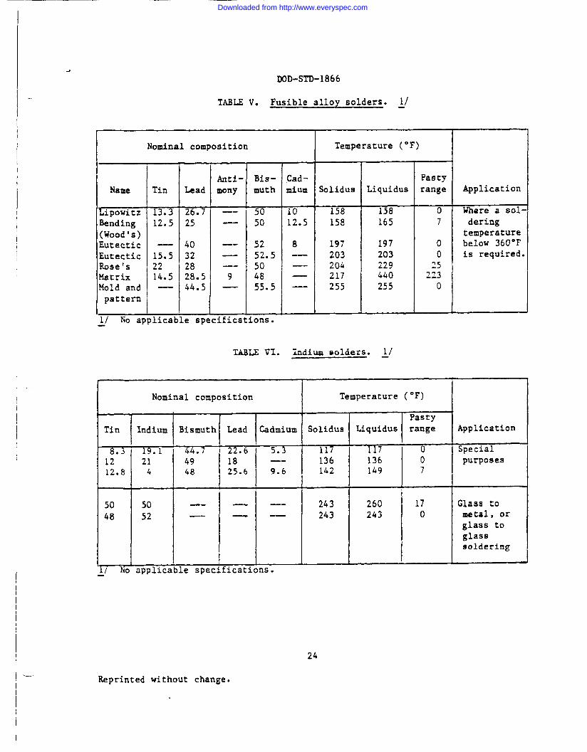
TABu v. Fusible alloy solders. ~/
Nominal composition Temperature (“F)
1
Anti- Bis- Cad- PaBtyName Tin Lead mony muth ~um Solidus Liquidus range Application
Lipowitz 13.3 26.7 —- 50 10 158 158 0 Where a sol-Bending 12.5 25 —- 50 12.5 158 165 7 dering(Wood’s) temperatureEutectic — 40 —- 52 8 197 197 0 below 360”FEutectic 15.5 32 — 52.5 —- 203 203 0 is required.Rose’s 22 28 —- 50 —- 204 229 ~5Matrix 14.5 ?8.5 9 48 — 217 440 -63a.?
Mold and —- 44.5 — 55.5 —- 255 255 0pattern
.,.. .. ... ..1/ No applicable speciticatlons.
TABLE VI. Xndium solders. ~1
Tin
n121208
5048
Nominal composition
Iridium
19.1214
5052
Bismuth Lead Cadmium
44.7 ‘ 22.6 5.349 18 —-48 25.6 9.6
—- ---—- -—
le specifications.I
,
Temperature (“F)
Solidus
--i-i7-136142
243243
=F=lApp,,-i117 ‘ o Special
136 0 purposes149 7
250 17 Glass to243 0 metal, or
glass toglasssoldering
‘-
I
24
Reprinted without change.
Downloaded from http://www.everyspec.com
.
custodians :
Army - AT&r Force - 99
IX)D-STD-1866-
Preparing activity:
Army - AT
(Project SOLD-00L2)Review activities:
Army - MI, AR, AV, MC
User activities:Army - ME
Navy - OS
24a
Downloaded from http://www.everyspec.com
-.. J
I
.
1-
OFFICIAL BLJSINES●ENALTY FOR ●BIVATE USE $300
Au C?. f-n L-M. LFtvuo
●O$TAGE ANO FEES ~AIO
o
*
U*U
CoumanderUS Army Tank-Automotive CousnandAITN: AMSTA-GDS
Warren, Michigan 48397-5000
FOLO
I
I-----
I
Downloaded from http://www.everyspec.com
—
b
..
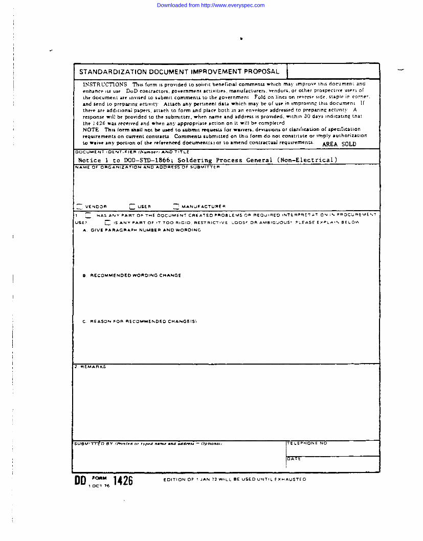
STANDARDIZATION DOCUMENT IMPROVEMENT PROPOSAL \I
lNSTRIJ~ONS Thts form ,$provtded tOSOIICIt bwwr)clal comments which may lmprovp this documeni and
●nhance 11.suse DoD contractors. government activities, mnufacLurers, vendors, or other prosp-ct)ve users of
lhe documenl are inviled LO submit comments to the government Fold on hncs on revsvw side, staplo In comer,
and send to prepar)ngactjv)ty Attach any Pertinent data which may beef usem tmprovlnc Lhisdocumcni Ifthere are addlt)onal papers, attach to form anrf place both In an envelope addre=ed IO Prepamnc act~nl! ~
response WIII be provided to the submitter, when name and address IS provided. wlthln 30 days Indlcatlng ~ha~
the 1426 was recewed and when any ●ppropriate act]on on It WI]] be completrd
t40TE ThIC (orm shall not beuaed tosubmjt que6wfor waivers. deviations orcl~)fitition o[s~cificaLion
requwements on current contracts. Commenwsubmltted on thts form do no( constitute or imply author! zatlon
lo watve any portton of the referenced docttmenl(s ) or to ●mend contractual requwements. AREA SOLD>OCUMENT IDENTIFIER ~h’umorr{ AND TITLE
Notice 1 to DOD–STD-1866; Soldering Process General (Non-Electrical).AAME OF ORGANIZATION AND AODRESS OF SUBMITTER
: VENDOR ~ uSER ~ MANuFACTURER
HAS ANY PART OF THE DO C,JMENT CREATED PRQ9LEMSOR REQuIRED !NTEqp QETAT!ON I% PRO C’U=EVE”4T
JSE? ~. IS ANV PAR? OF !7 TOO RIGID, aES7Rl CTl VE LOOSF OR AM BIG UOUS~ PLEASE EXPLAI% BE LOti
A GIVE PARAGRAPH NUMBER ANO wORDING
s. RECOMMENDED WOROING CHANGE
C. REASON FOR RECOMMENDED CHANGE IS)
nEMARKS
ID,[::6 1426 EOITION OF 1 JAN 72WILL SE US EOUNTILEXHAUSTEO
Downloaded from http://www.everyspec.com


![9]~. . 411..-CJIK4..!.?.!:! SUPERSEDING MIL-S-6872B 14 ...everyspec.com/DoD/DoD-STD/download.php?spec=DOD... · DEPARTMENT OF !XFEKSL WASHINGTON, DC 20301 1. This Military Standard](https://static.fdocuments.in/doc/165x107/5f6d037501109c20b24e9476/9-411-cjik4-superseding-mil-s-6872b-14-department-of-xfeksl.jpg)