
DoD Installation Visualization Tool Quality … BRAC Rounds...DoD Installation Visualization Tool...
94
DoD Installation Visualization Tool Quality Assurance Plan Version 1.1 31 December 2003 Prepared by the IVT Program Office Headquarters Air Force Geo Integration Office Office of the Civil Engineer DCS/Installations & Logistics 1260 Air Force Pentagon Washington DC 20330-1260
Transcript of DoD Installation Visualization Tool Quality … BRAC Rounds...DoD Installation Visualization Tool...

DoD Installation Visualization Tool
Quality Assurance Plan
Version 1.1
31 December 2003
Prepared by the IVT Program Office
Headquarters Air Force Geo Integration Office Office of the Civil Engineer
DCS/Installations & Logistics 1260 Air Force Pentagon
Washington DC 20330-1260

DOD INSTALLATION VISUALIZATION TOOL QUALITY ASSURANCE PLAN VERSION 1.1
This page intentionally left blank
31 DECEMBER 2003 1

DOD INSTALLATION VISUALIZATION TOOL QUALITY ASSURANCE PLAN VERSION 1.1
Document History Version Primary
Authors Description Date Completed
Draft 1.A IVT Technical Working Group
Draft QAP for auditor review/approval at the 10 Sep 03 BRAC Joint Audit Planning Commission meeting.
Draft 1.A compiled by the OSD IVT Office, HQ USAF/ILE-I, with inputs from the IVT Technical Working Group (TWG) and Service Mission Knowledge (Subject Matter) Experts.
9 Sep 03
1.0 IVT Technical Working Group
Revised QAP based on inputs from the Joint Audit Planning Commission, IVT Integrated Product Team, Working Group, and TWG received as of 9 Oct 03.
Version 1.0 of the QAP was formally distributed to the Services accompanied by an Service-signed and issued cover letters.
31 Oct 03
1.1 IVT Program Office
Revised QAP incorporating additional capabilities approved by the Infrastructure Steering Group, results from the 5 Dec 03 IVT Working Group meeting, and technical clarifications issued since the 31 Oct 03 release of QAP Version 1.0.
31 Dec 03
31 DECEMBER 2003 2

DOD INSTALLATION VISUALIZATION TOOL QUALITY ASSURANCE PLAN VERSION 1.1
Executive Summary The Installation Visualization Tool (IVT) Quality Assurance Plan (QAP) defines geospatial data and metadata content specifications, data handling procedures, and validation methodology for IVT to supplement Base Realignment and Closure (BRAC) 2005 analysis. This QAP is consistent with the IVT Charter approved by the IVT Integrated Process Team (IPT).
The IVT Technical Working Group (TWG) developed the QAP with support from mission knowledge (subject matter) experts within the Services and with oversight from the BRAC Joint Audit Planning Group and the IVT IPT.
IVT provides the BRAC 2005 process a means of viewing imagery and geospatial data in a consistent fashion for all installations meeting BRAC 2005 threshold criterion. Each Service will define and publish a unique plan and procedure for using IVT during their BRAC 2005 process. IVT will provide the ability to visualize the installation and associated range complexes using an overhead (satellite) image of each installation or activity meeting BRAC Section 2687 threshold manpower criteria, installation/range boundary, and significant “exclusion zone” criteria depicting areas of the installation or range not available to accept realigned missions from closed installations. Each criterion is depicted on a map overlay layer.
The IVT QAP provides specifications and minimum standards for IVT data and metadata to be delivered to the OSD IVT Office. The QAP also provides guidance for the Services to identify acceptable IVT data sources and to perform quality assurance and quality control (QA/QC) before submittal to the OSD IVT Office Internal controls and chain-of-custody necessary for handling and releasing of IVT data and metadata are also outlined in the QAP.
During the BRAC 2005 process, the Services will provide certified responses to BRAC data call questions. Several BRAC data call questions directly address constraints to realignment and request information on constraint factors visualized in IVT. In these cases, the certified responses should be developed using the same sources used for the IVT pictures. Should IVT conflict with the BRAC data call, in all cases, the BRAC data call will prevail as the definitive answer.
31 DECEMBER 2003 3

DOD INSTALLATION VISUALIZATION TOOL QUALITY ASSURANCE PLAN VERSION 1.1
Table of Contents Document History ....................................................................................................................................... 2
Executive Summary .................................................................................................................................... 3
1.0 Purpose .................................................................................................................................................. 7
2.0 Authority................................................................................................................................................ 7
3.0 Applicability .......................................................................................................................................... 8
4.0 Contents ................................................................................................................................................. 8
5.0 IVT Data Requirements ....................................................................................................................... 9 5.1 Data Content ....................................................................................................................................... 9 5.2 Geographic Extent ............................................................................................................................ 10 5.3 Data Organization – SDSFIE............................................................................................................ 11 5.4 Metadata – FGDC CSDGM.............................................................................................................. 12 5.5 Delivery Format ................................................................................................................................ 13
5.5.1 Imagery.................................................................................................................................... 13 5.5.2 IVT Overlay Layers................................................................................................................. 13
6.0 IVT Data Collection Guidelines......................................................................................................... 15 6.1 Relationship Between IVT and Certified BRAC Data ..................................................................... 15 6.2 Data Source Identification ................................................................................................................ 16 6.3 Time Period of Source Data Content ................................................................................................ 17 6.4 Positional Accuracy .......................................................................................................................... 17
6.4.1 Positional Accuracy Thresholds for IVT Imagery................................................................... 18 6.4.2 Positional Accuracy Thresholds for IVT Overlay Layers ....................................................... 18 6.4.3 Reporting IVT Content Positional Accuracy........................................................................... 18
6.4.3.1 National Standards for Spatial Data Accuracy (NSSDA) .......................................................................... 18 6.4.3.2 National Map Accuracy Standards (NMAS) ............................................................................................. 19
6.5 Content Accuracy.............................................................................................................................. 19 6.5.1 Ground Truthing and Error Matrices....................................................................................... 20
6.6 Converting Hardcopy (Paper) Sources to Digital Geospatial Data................................................... 21 6.7 Georeferencing IVT Data Sources .................................................................................................... 23
7.0 IVT Data Specifications...................................................................................................................... 24 7.1 Imagery ............................................................................................................................................. 24
7.1.1 Description .............................................................................................................................. 24 7.1.2 Imagery Specifications ............................................................................................................ 25
7.1.2.1 Imagery Extent Definition ......................................................................................................................... 26 7.1.3 Sources and Source Selection Criteria..................................................................................... 26 7.1.4 Imagery Certification............................................................................................................... 27
7.1.4.1 Imagery Assessment Methodology............................................................................................................ 27 7.1.4.2 Imagery Assessment Results ..................................................................................................................... 27
7.1.5 Imagery QA/QC and Acceptance Procedures ......................................................................... 28 7.2 Installation Boundary........................................................................................................................ 28
7.2.1 Description .............................................................................................................................. 28 7.2.2 Policy and Regulations ............................................................................................................ 29 7.2.3 Geographic Representation...................................................................................................... 29
31 DECEMBER 2003 4

DOD INSTALLATION VISUALIZATION TOOL QUALITY ASSURANCE PLAN VERSION 1.1
7.2.4 Valid Sources and Source Selection Criteria........................................................................... 29 7.2.4.1 Recording the Selected Source in IVT Metadata ....................................................................................... 31
7.2.5 File Name and Attributes......................................................................................................... 31 7.3 Range Complex Boundary ................................................................................................................ 32
7.3.1 Description .............................................................................................................................. 32 7.3.2 Policy and Regulations ............................................................................................................ 33 7.3.3 Geographic Representation...................................................................................................... 33 7.3.4 Valid Sources and Source Selection Criteria........................................................................... 33
7.3.4.1 Recording the Selected Source in IVT Metadata ....................................................................................... 34 7.3.5 File Name and Attributes......................................................................................................... 34
7.4 Noise Contours.................................................................................................................................. 35 7.4.1 Description .............................................................................................................................. 35 7.4.2 Policy and Regulations ............................................................................................................ 36 7.4.3 Geographic Representation...................................................................................................... 36 7.4.4 Valid Sources and Source Selection Criteria........................................................................... 37
7.4.4.1 Recording the Selected Source in IVT Metadata ....................................................................................... 38 7.4.5 File Name and Attributes......................................................................................................... 38
7.5 Accident Potential Zone.................................................................................................................... 39 7.5.1 Description .............................................................................................................................. 39 7.5.2 Policy and Regulations ............................................................................................................ 41 7.5.3 Geographic Representation...................................................................................................... 41 7.5.4 Valid Sources and Source Selection Criteria........................................................................... 42
7.5.4.1 Recording the Selected Source in IVT Metadata ....................................................................................... 42 7.5.5 File Name and Attributes......................................................................................................... 42
7.6 Explosive Safety Quantity Distance (ESQD) Arcs........................................................................... 43 7.6.1 Description .............................................................................................................................. 43 7.6.2 Policy and Regulations ............................................................................................................ 43 7.6.3 Geographic Representation...................................................................................................... 44 7.6.4 Valid Sources and Source Selection Criteria........................................................................... 45
7.6.4.1 Recording the Selected Source in IVT Metadata ....................................................................................... 45 7.6.5 File Name and Attributes......................................................................................................... 45
7.7 Floodplain – 100-Year ...................................................................................................................... 46 7.7.1 Description .............................................................................................................................. 46
7.7.1.1 Representing Flood Events Other Than the 100-Year Flood ..................................................................... 47 7.7.2 Policy and Regulations ............................................................................................................ 48 7.7.3 Geographic Representation...................................................................................................... 48 7.7.4 Valid Sources and Source Selection Criteria........................................................................... 48
7.7.4.1 Recording the Selected Source in IVT Metadata ....................................................................................... 49 7.7.5 File Name and Attributes......................................................................................................... 49
7.8 Wetlands ........................................................................................................................................... 50 7.8.1 Description .............................................................................................................................. 50 7.8.2 Policy and Regulations ............................................................................................................ 51 7.8.3 Geographic Representation...................................................................................................... 51 7.8.4 Valid Sources and Source Selection Criteria........................................................................... 51
7.8.4.1 Recording the Selected Source in IVT Metadata ....................................................................................... 52 7.8.5 File Name and Attributes......................................................................................................... 53
7.9 Range Complex Airspace.................................................................................................................. 54 7.9.1 Description .............................................................................................................................. 54 7.9.2 Policy and Regulations ............................................................................................................ 56 7.9.3 Geographic Representation...................................................................................................... 56
31 DECEMBER 2003 5

DOD INSTALLATION VISUALIZATION TOOL QUALITY ASSURANCE PLAN VERSION 1.1
7.9.4 Valid Sources and Source Selection Criteria........................................................................... 56 7.9.5 File Name and Attributes......................................................................................................... 56
7.9.5.1 Special Use Airspace ................................................................................................................................. 57 7.9.5.2 Military Training Routes ........................................................................................................................... 58 7.9.5.3 Air Refueling Tracks ................................................................................................................................. 59 7.9.5.4 Nonattainment Areas ................................................................................................................................. 59
8.0 Quality Assurance and Internal Controls......................................................................................... 60 8.1 Certification and Approval................................................................................................................ 61 8.2 IVT Data Collection and Quality Assurance/Quality Control Procedures ....................................... 61
8.2.1 Step 1: Determine Applicability of IVT Layer........................................................................ 63 8.2.2 Step 2: Data Source Selection ................................................................................................. 63 8.2.3 Step 3: Conversion to IVT Specifications ............................................................................... 63 8.2.4 Step 4: Quality Assurance/Quality Control (QA/QC) ............................................................. 64 8.2.5 Step 5: Approval by Base-Level Command Authority............................................................ 64
8.2.5.1 Chain of Custody ....................................................................................................................................... 66 8.2.5.2 Obtaining Signature for Range Complex Boundaries................................................................................ 66
8.2.6 Step 6: Acceptance by OSD IVT Office.................................................................................. 66 8.2.7 Step 7: Random Selection for Auditor Validation (Optional) ................................................. 67 8.2.8 Step 8: Auditor Validation (Optional) ..................................................................................... 68 8.2.9 Step 9: Submittal to IVT Repository ....................................................................................... 70
8.3 Record Keeping ................................................................................................................................ 70 8.3.1 Disclaimers .............................................................................................................................. 70 8.3.2 IVT Portfolio for Base-Level Command Authority Signature ................................................ 71 8.3.3 Releasibility............................................................................................................................. 71
8.3.3.1 Audit Access to Records............................................................................................................................ 71 8.3.3.2 Dissemination ............................................................................................................................................ 71 8.3.3.3 Access to IVT Data.................................................................................................................................... 71 8.3.3.4 Distribution Format ................................................................................................................................... 72
8.3.4 Non-Disclosure Agreements.................................................................................................... 72 Appendix A - References .......................................................................................................................... 73
Appendix B – IVT Metadata Requirements........................................................................................... 76 Section 1 – Identification ........................................................................................................................ 76 Section 2 – Data Quality Information ..................................................................................................... 82 Section 3 – Spatial Data Organization Information ................................................................................ 86 Section 4 – Spatial Reference Information ............................................................................................. 87 Section 5 – Entity and Attribute Information.......................................................................................... 87 Section 6 – Distribution Information ...................................................................................................... 88 Section 7 – Metadata Reference Information.......................................................................................... 88
Appendix C – DoD/Title 50 License Agreement for IVT Imagery ....................................................... 92
31 DECEMBER 2003 6

DOD INSTALLATION VISUALIZATION TOOL QUALITY ASSURANCE PLAN VERSION 1.1
1.0 Purpose This Quality Assurance Plan (QAP) defines data and metadata content specifications, data handling and certification procedures, and validation methodology for the Installation Visualization Tool (IVT) to supplement Base Realignment and Closure (BRAC) 2005 analysis.
IVT capabilities are being established to further the objectives set forth in the 15 Nov 02 Secretary of Defense Memorandum, Transformation Through Base Realignment and Closure. In particular, the Secretary stated:
“A primary objective of BRAC 2005, in addition to realigning our base structure to meet our post-Cold War force structure, is to examine and implement opportunities for greater joint activity. Prior BRAC analyses considered all functions on a service-by-service basis and, therefore, did not result in the joint examination of functions that cross Services. While some unique functions may exist, those functions that are common across the Services must be analyzed on a joint basis.”
IVT will provide the BRAC 2005 process additional means of viewing installation data in a consistent fashion for all installations meeting BRAC Section 2687 threshold manpower criteria. Each Service will define and publish a unique plan and procedure for using IVT during their analytical process. The validated BRAC questionnaire data is always the overriding data source. IVT simply provides a complimentary geospatial supplement to deliberative data and a starting point for further analysis.
2.0 Authority The Undersecretary of Defense for Acquisition, Technology, and Logistics (USD/AT&L) released the Transformation through Base Realignment and Closure (BRAC 2005) Policy Memorandum One – Policy, Responsibilities, and Procedures (“BRAC Policy Memo No. One”) on 16 Apr 03. Guidance in BRAC Policy Memo No. One applies to the Military Departments and Defense Agencies (DoD Components) and JCSGs in developing the Secretary of Defense’s base realignment and closure recommendations for submission to the BRAC 2005 Commission for its review.
BRAC Policy Memo No. One identifies IVT as a capability to enhance the Department’s overall ability to manage its infrastructure that shall be used as a tool during the BRAC 2005 process. The BRAC Infrastructure Steering Group (ISG) has developed requirements for use of IVT through an Integrated Process Team (IPT) established by USD (AT&L). This IPT – comprised of the OSD Director and Military Department Deputy Assistant Secretaries for BRAC – has directed that IVT will be used as an installation visualization capability to supplement BRAC capacity analysis and realignment planning decisions.
31 DECEMBER 2003 7

DOD INSTALLATION VISUALIZATION TOOL QUALITY ASSURANCE PLAN VERSION 1.1
3.0 Applicability
Services will provide IVT data for DoD owned and leased installations, sites, or facilities1 to which Title 10 USC Section 2687 applies. Section 2687 (referred to herein as “BRAC Section 2687 threshold manpower criteria”) applies to the closure of any military installation where 300 or more direct hire permanent civilians are authorized to be employed. Title 10 USC Section 2687 defines a “military installation” as
Any base, camp, post, station, yard, center, homeport for facility for any ship, or other activity under the jurisdiction of the Department of Defense, including any leased facility, which is located within any of the United States, the District of Columbia, the Commonwealth of Puerto Rico, American Samoa, the Virgin Islands, or Guam. Such term does not apply to any facility used primarily for civil works, rivers and harbors, projects, or flood control projects.
Section 2687 also applies to the realignment of any military installation at which 300 or more DoD direct hire permanent civilians are authorized to be employed if the realignment will result in the reduction by more than 1000, or by more than 50 percent, in the number of DoD direct hire permanent civilians authorized to be employed at that installation.
Services may elect, at the discretion of their respective BRAC offices, to exclude leased facilities meeting BRAC Section 2687 threshold manpower criteria from IVT in the event those employees are located within leased space in an office building for other uses (e.g., U.S. Navy Engineering Field Activity Northeast - EFA NE - located in leased space in an office building in Philadelphia, PA). In these cases, imagery and overlay layers lend little if any value for interpreting relevant BRAC criteria at these sites.
4.0 Contents The IVT QAP provides:
• Specifications and minimum standards for IVT data and metadata to be delivered by the Services to the IVT Office, including common specifications across all Services and identification of Service-specific issues and constraints;
• Guidance for the Services to identify acceptable IVT data sources, assess validity of data sources, and document selected data sources in IVT metadata, and perform quality assurance and quality control (QA/QC) of data/metadata before submittal to the IVT Office;
• Acceptance criteria for IVT Office QA/QC of data and metadata received from the Services;
• Guidance on sampling and validating the positional and content accuracy of randomly selected IVT data and metadata by BRAC auditors, if desired, and
1 Interim DoD Instruction 4165.14, Department of Defense Real Property Inventory Reporting and Forecasting, 19 Aug 02, defines “installation” as a single site (e.g., Pope AFB) or a grouping of two or more sites (e.g., Ft Belvoir as the main installation and Woodbridge Housing as a subordinate site) for the purposes of inventory control. DoDI 4165.14 defines a “site” as a contiguous geographic area owned or leased by a Military Department.
31 DECEMBER 2003 8

DOD INSTALLATION VISUALIZATION TOOL QUALITY ASSURANCE PLAN VERSION 1.1
• Internal control plan (ICP) for the handling and releasibility of IVT data and metadata;
5.0 IVT Data Requirements 5.1 Data Content IVT will provide the ability to visualize the installation and associated range complexes using an overhead (satellite) image of each reservation, installation/range boundary, and significant “exclusion zone” criteria depicting areas of the installation or range not available to accept realigned missions from closed installations. Each criteria is portrayed on a map overlay layer:
IVT imagery: • 1-meter resolution imagery for installations or installation cantonment areas; • 5-meter resolution imagery for range complexes;
IVT overlay layers: 1. Installation boundaries; 2. Range complex boundaries; The following “exclusion zone” layers will be provided for each installation and associated range complex shown in IVT, where applicable: 3. Noise contours >65 decibels (>60 decibels in California); 4. Clear Zones and Accident Potential Zones; 5. Explosive Safety Quantity Distance (ESQD) arcs; 6. 100-year floodplains; 7. Wetlands;
The following overlay layer will be provided as a ‘seamless’ nationwide overlay: 8. Range Complex Airspace - depicting operational interdependencies on and between DoD ranges.
This layer depicts special use airspace, military training routes, air refueling tracks, and nonattainment areas.
Detailed specifications and guidance are provided for each IVT data layer in Section 7. Figure 5-1 illustrates an example of IVT overlay layers for a DoD installation:
31 DECEMBER 2003 9

DOD INSTALLATION VISUALIZATION TOOL QUALITY ASSURANCE PLAN VERSION 1.1
Figure 5-1 IVT Overlay Layers
Figure 5-2 illustrates the relationship between installation and range geographies. For US Army and several US Marine Corps reservations, ranges are located within the installation boundary itself. Non-range (cantonment) areas will be visualized using 1-meter resolution imagery. US Air Force and US Navy air-to-surface ranges are typically geographically separate from the associated installation:
Figure 5-2 Installations and Range Complexes
5.2 Geographic Extent IVT data will extend beyond the installation or range complex boundary to enable understanding of the impact of military operations on the surrounding communities, and to visualize community encroachment on military reservations:
• 1-meter and 5-meter imagery – Will extend one mile beyond the furthest extent of the installation or range complex boundary, noise contours, accident potential zones, or explosive safety quantity distance arcs as defined in Section 7.1.2.1 and shown in Figure 5-3;
• IVT overlay layers depicting military operations – Noise contours, accident potential zones, and explosive safety quantity distance arcs will be mapped to their fullest extent beyond the installation boundary, and will not be artificially “broken” (split) at the installation boundary;
31 DECEMBER 2003 10

DOD INSTALLATION VISUALIZATION TOOL QUALITY ASSURANCE PLAN VERSION 1.1
• IVT overlay layers depicting environmental constraints – 100-year floodplains and wetlands will be mapped at a minimum within the installation boundary. Services may, at the discretion of the Service BRAC office, elect to depict wetlands and floodplains up to one mile beyond the installation boundary at their discretion. In the event that wetlands and floodplains extend beyond the installation boundary, and different sources are used for the wetlands and floodplains on- and off-base, those polygons may be split at the installation boundary to separate those wetlands/floodplains inside the installation property from those outside the boundary.
Figure 5-3 IVT Data Geographic Extent
• Range complex airspace - Special use airspace, military training routes, and air refueling tracks will be depicted for the CONUS AOR, Alaska, Hawaii, Puerto Rico, and near-shore waters in U.S. and international territory. Nonattainment areas will be shown by highlighting those counties in the CONUS AOR, Alaska, and Hawaii with nonattainment status (as described further in Section 7.9).
5.3 Data Organization – SDSFIE IVT overlay layers will be organized using the American National Standards Institute (ANSI) National Committee for Information Technology Standard (NCITS) 353, also known as the Spatial Data Standards for Facilities, Infrastructure, and Environment (SDSFIE), Version 2.222. The SDSFIE is a vendor-neutral geospatial data content standard designed for use with predominant commercial off-the-shelf (COTS) geographic information system (GIS) and computer-aided drafting and design (CADD) software. All Services organize their installation geospatial data as per Service Policy:
• US Air Force – 7 Oct 02 AF/IL USAF GeoBase Policy Memo;
• US Army – 16 Oct 01 DAIM-MD (AR 210-20) Data Standards for Computer Aided Drafting and Design (CADD), Geographic Information Systems (GIS), and Related Technologies;
• US Navy – 8 Dec 99 HQ Naval Facilities Engineering Command Interim Policy Guidance for CADD, GIS, and Related Technologies and 2 Nov 99 SECNAV DoN Policy on Digital Logistics Technical Data;
2 With the exception of the Range Complex Airspace layer, as described in Section 7.9.5.
31 DECEMBER 2003 11

DOD INSTALLATION VISUALIZATION TOOL QUALITY ASSURANCE PLAN VERSION 1.1
• US Marine Corps – 15 Apr 03 HQ USMC Guidance Regarding Implementation of Geospatial Information Systems (GIS) and Related Technologies for Installation Management.
The SDSFIE provides a standard RDBMS data model defining:
• Map Layer/Table names – Each SDSFIE table corresponds to a map layer. Real-world phenomena are logically grouped by the SDSFIE into entity sets, further classified into entity classes, and then organized into entity types – each entity type being associated with a single map layer;
• Table attributes - Information describing map features, including column names, order, data type (character, numeric), and column width;
• Attribute domains - Listing valid attribute values for any given attribute column;
• Relationships - Relationships between SDSFIE tables and between tables and relevant attribute domains.
The SDSFIE are developed and maintained by the CADD/GIS Technology Center for Facilities, Infrastructure, and Environment located in the U.S. Army Engineer Research and Development Center's Information Technology Laboratory in Vicksburg, MS. The SDSFIE are developed in a collaborative fashion with input from DoD Services and other Federal organizations.
IVT overlay layers will utilize SDSFIE table names, attributes, and attribute (valid value) domains. Each IVT table (overlay layer) will contain the full suite of SDSFIE attribute fields, to meet the “basic level” of compliance as per 23 Oct 02 compliance policy established by the CADD-GIS Technology Center. However, only a small number of attribute fields will be populated in IVT. Specific attributes that are to be provided for IVT are defined in Section 7. The IVT Office will provide empty templates of each IVT overlay layer, containing the full suite of SDSFIE attributes, for use by the Services. The full suite of attribute fields, including field definitions, field order, etc. can be viewed using the SDSFIE Browser, downloadable from the CADD-GIS Technology Center web site at http://tsc.wes.army.mil/products/TSSDS-TSFMS/tssds/html/.
5.4 Metadata – FGDC CSDGM IVT data – imagery and overlay layers – will be documented using metadata, organized by the Federal Geographic Data Committee (FGDC) Content Standards for Digital Geospatial Metadata (CSDGM), as per Executive Order 12906, Coordinating Geographic Data Acquisition and Access: The National Spatial Data Infrastructure (NSDI), 11 Apr 94 and Office of Management and Budget (OMB) Circular A-16, Coordination of Geographic Information and Related Spatial Data Activities, 3 Jul 01.
The CSDGM provide a common set of terminology and definitions for the documentation of digital geospatial data. Metadata are a critical element of the IVT; metadata accompany each IVT data layer and describe the data source, lineage, accuracy, contents, data quality, organization, spatial reference, and distribution constraints. The CSDGM is vendor-neutral and metadata organized by the CSDGM can be developed and maintained using any number of COTS and government-developed products.
The CSDGM classifies metadata elements as “mandatory”, “mandatory if applicable” (i.e., the metadata element must be included if the data set exhibits the defined characteristic), and “optional”. IVT will be documented using metadata elements classified as mandatory and mandatory-if-applicable, and will utilize standard values as defined in Appendix B and Section 7.
31 DECEMBER 2003 12

DOD INSTALLATION VISUALIZATION TOOL QUALITY ASSURANCE PLAN VERSION 1.1
Appendix B defines metadata requirements for all IVT layers, and IVT layer-specific metadata requirements in addition to those defined in Appendix B are defined in Section 7.
More information on the CSDGM can be found at http://www.fgdc.gov/metadata/metadata.html.
5.5 Delivery Format 5.5.1 Imagery 1-meter and 5-meter resolution images are being acquired centrally by the IVT Office as described in Section 7.1. Imagery files (one set of imagery for each DoD installation or facility meeting the Section 2687 threshold manpower criterion) will be delivered to the IVT Office as uncompressed binary files in GeoTIFF format. The IVT Office may in turn compress the image files and save in alternate formats (such as MrSID) to reduce file size and improve performance on standard DoD computer workstations. Should the imagery be compressed, compression will be performed such that imagery resolution is not compromised and no horizontal (positional) error is introduced.
Each imagery file will be accompanied by a metadata file, formatted as per metadata requirements defined in Section 5.4, describing its properties, content, lineage, accuracy, source, etc. The IVT Office will centrally develop imagery metadata.
Imagery certification procedures are described in Section 7.1.4.
5.5.2 IVT Overlay Layers IVT overlay layers will be delivered to the IVT Office meeting the following specifications. Overlay layer files shall be delivered on an installation-by-installation basis (e.g., one wetland file for Ft Belvoir, VA, another wetland file for Ft A.P, Hill, VA, etc.), not as a single “seamless” data set depicting multiple installations. The OSD IVT Office will compile overlay layers for the IVT Range Complex Airspace theme centrally; Services are not responsible for compiling or delivering Range Complex Airspace overlay layers. The Range Complex Airspace overlay is described further in Section 7.9.
Service IVT Offices may elect to acquire additional attribution beyond that required for IVT from its installations. However, these attributes shall be removed from the data to be submitted to the IVT Office.
Geographic Model: Vector data; each feature depicted in IVT represented as a complete,
closed polygon with no “gaps” in the polygon boundary. File Type: ESRI shapefile 3
Each shapefile is comprised of the following components, all of which must be delivered to the IVT Office: {filename}.SHP – Main shape file containing feature geometry; {filename}.SHX – Index file; {filename}.DBF – Attribute table; {filename}.PRJ – Projection file containing coordinate information;
3 Shapefiles are a non-proprietary geospatial data format published by Environmental Systems Research Institute, Inc. (ESRI). ESRI is a leading vendor of COTS GIS and mapping products and represents the majority of DoD investment in COTS products for installation mapping and visualization. Shapefiles are a de-facto industry standard for geospatial data exchange and can be created
31 DECEMBER 2003 13

DOD INSTALLATION VISUALIZATION TOOL QUALITY ASSURANCE PLAN VERSION 1.1
File Name: File names will be defined by SDSFIE entity type naming conventions and must be one of the following valid values: INSTALLATION_AREA – Installation boundaries MILITARY RANGE_AREA – Range complex boundaries NOISE_ZONE_AREA – Noise contours AIR_ACCIDENT_ZONE_AREA – Clear Zones and Accident potential zones MILITARY_QUANTITY_DISTANCE_ARC_AREA – Explosive safety quantity distance arcs FLOOD_ZONE_AREA – 100-year floodplains WETLAND_AREA – Wetlands
Geospatial Registration: Each shapefile must contain a projection file (*.PRJ) defining: Map Projection: Universal Transverse Mercator (UTM), UTM Zone dependent on
location of the DoD installation/facility4 Datum: World Geodetic System of 1984 (WGS 84), Geodetic Reference
System 1980 (GRS80) spheroid Map Units: Meters
Attribution: IVT shapefiles will be delivered with attribute fields, field definitions, and field order defined by the SDSFIE, with several custom fields as per Section 7. All SDSFIE fields will remain in the IVT shapefile attribute tables. Section 7 defines specific attribute table structure and the attribute fields that must be populated for each IVT overlay layer. All other SDSFIE attribute fields will remain empty upon delivery to the OSD IVT Office. The IVT overlay layer attribute tables may contain addition fields created by the GIS/mapping software used for data management. Services should remove these fields where possible. Any fields added and maintained by the GIS/mapping software to store feature area (e.g., ‘SHAPE_AREA” in ESRI ArcGIS) should either be removed or left blank; IVT overlay layers shall not include feature area as an attribute. All attribute values in the IVT overlay layer attribute tables shall be entered in either upper case (capitalized) or title case (first letters capitalized), as per the attribute definitions in QAP Section 7, to facilitate development of common map legends (which are case-sensitive) and standard IVT Overlay Layer database queries (also case-sensitive).
and viewed in a variety of COTS GIS/mapping products from numerous vendors as ESRI has published the shapefile data model in the public domain. 4 In the event that an installation falls in two UTM zones, Services should choose the most appropriate zone for the installation, as there should be relatively little distortion (positional shifting) at the edges of each UTM zone. In the event that significant distortion occurs using the UTM projection for any particular installation, Services shall contact the OSD IVT Office to coordinate the use of projections other than UTM.
31 DECEMBER 2003 14

DOD INSTALLATION VISUALIZATION TOOL QUALITY ASSURANCE PLAN VERSION 1.1
Metadata: Metadata, organized by the FGDC CSDGM, in XML format (preferred) or SGML format (alternative), named in the following fashion to be compatible with ESRI ArcGIS software: {filename}.SHP.XML – Metadata, in extensible markup language {filename}.SHP.SGML – Metadata, in standard generalized markup language The provided metadata file must be compatible with ESRI ArcCatalog metadata import tools.
6.0 IVT Data Collection Guidelines IVT overlay layers will be provided to the OSD IVT Office for each installation meeting the BRAC Section 2687 threshold manpower criterion. IVT overlay layers must be compliant with specification defined in Sections 6 and 7 upon delivery to the OSD IVT Office. IVT overlay layers and metadata will be presented to the base-level command authority for signature to acknowledge the sources used for each IVT overlay layer, metadata for each layer, and the picture being shared with the IVT Office. Upon signature by the base-level command authority, IVT data content will be delivered as-is with no subsequent modification.
Prior to submitting IVT data layers to the base-level command authority for signature, mission knowledge experts (subject-matter experts) within the services will identify the best available data source(s) for each IVT layer. Valid sources may be currently available in digital electronic format or in hardcopy/paper format. Data portrayed in hardcopy format or in tabular format must be converted to geographic features for inclusion in IVT.
6.1 Relationship Between IVT and Certified BRAC Data During the BRAC 2005 process, seven Joint Cross-Service Groups and the Military Departments will develop questions to be used in capacity, military value, and scenario-specific realignment analyses. The questions will be released to the Services in a series of BRAC data calls. The Services and Defense Agencies will provide certified responses to all questions in accordance with their respective internal control plans.
Several questions may directly address constraints to realignment and may request information on constraint factors visualized in IVT (e.g., total area of wetlands, total area impacted by noise, or total area of floodplains, etc. at an installation meeting BRAC Section 2687 threshold manpower criterion). The IVT data collection process must seek to ensure accurate visual interpretation of certified BRAC data.
The same source(s) should be selected, where possible, to ensure equivalency between the pictorial representation in IVT and the certified BRAC data. IVT data sources should be selected by mission knowledge experts within each Service rather than by the Service IVT coordinators. In this fashion the DoD is assured that the IVT picture portrays conditions at each installation in a fashion consistent with certified BRAC data responses.
31 DECEMBER 2003 15

DOD INSTALLATION VISUALIZATION TOOL QUALITY ASSURANCE PLAN VERSION 1.1
However, recognizing propagation of error associated with converting sources to digital geospatial data and, in some cases, different sources being used to respond to BRAC questions and to develop IVT pictures, there is no requirement that the pictorial representation of realignment constraint factors exactly match the certified responses from the Services.
Recommended procedures for BRAC auditors to compare certified BRAC responses with the corresponding IVT pictures, for the purposes of validating the IVT data collection process, are provided in Section 8.2.8.
6.2 Data Source Identification Selection of sources for IVT data should be performed by relevant mission knowledge experts at the installation or elsewhere within the Service, to ensure equivalency between pictorial representations in IVT and certified BRAC responses as described in Section 6.1.
Sources for each IVT overlay layer should meet the following criteria (the same criteria may apply to source selection in response to relevant BRAC data call questions):
• Must be authorized for release to the IVT Office by the base-level command authority. These sources may or may not be currently in the public domain and must be unclassified;
• Should be one of the valid sources identified in Sections 7.2.4, 7.3.4, 7.4.4, 7.5.4, 7.6.4, 7.7.4, and 7.8.4, Valid Sources, herein. If none of the listed sources are available or appropriate, other sources may be used, and in these cases, noted in the IVT metadata as described below;
• Should be the most current source available up to 30 Sep 03 to help ensure visual equivalency with responses to the BRAC data call questionnaires, which will be current up to but not beyond 30 Sep 03;
• Should portray relevant conditions at the highest horizontal positional accuracy possible and should portray a complete representation of relevant conditions for a given IVT overlay layer at the installation;
• May be currently in either hardcopy/paper or digital format;
• Should be georeferenced (i.e., registered to a known coordinate system and projection). Sources that are not registered to a known coordinate system may be used if they can be georeferenced (see Section 6.7);
• May currently portray relevant phenomena and objects in geospatial/map format, or may portray relevant data that can be converted to a geospatial/map format;
• Local data sources (i.e., generated at the installation) should be considered before nationwide/Federal and/or statewide data sources. Consider state and Federal data sources when no viable local data sources are available;
• Mission knowledge experts at the installations and Services are responsible for identifying the most appropriate sources, with support from military department IVT coordinators and base-level GIS/mapping POCs.
31 DECEMBER 2003 16

DOD INSTALLATION VISUALIZATION TOOL QUALITY ASSURANCE PLAN VERSION 1.1
IVT coordinators amongst the Services, in coordination with installation-level mapping POCs and mission knowledge experts, should balance all of the above criteria to identify the most appropriate data source for each IVT overlay layer.
Multiple sources may be identified and used as necessary to develop any given IVT overlay layer. In these cases CSDGM metadata element 2.5, Source Citation, shall be repeated as many times as necessary to record each source as described in Appendix B.
In the event that a source other than the most-preferred source is selected for an IVT data set (as per Sections 7.2.4.1, 7.3.4.1, 7.4.4.1, 7.5.4.1, 7.6.4.1, 7.7.4.1, and 7.8.4.1), and more preferred sources were available, a short description justifying the selection of the lesser-preferred source shall be provided in CSDGM metadata element 2.5.1.1 (Source Citation 8.9, Other Citation Information) as described in Appendix B.
6.3 Time Period of Source Data Content IVT will use the best available sources to portray conditions at installations up to, but not later than, 30 Sep 03. Should the best available sources, as defined in Section 6.2, show conditions prior to 30 Sep 03, these sources may be selected. This cutoff date matches the delivery dates for certified responses to BRAC data calls, thereby reducing potential for visual mismatches with certified BRAC data.
The time period of the content depicted on selected IVT source materials will be recorded in CSDGM metadata element 1.3.
6.4 Positional Accuracy Information depicted in IVT overlay layers (such as installation boundaries, wetlands, ESQD arcs, etc.) should be mapped to the highest horizontal positional accuracy possible, given limitations of available sources for each IVT overlay layer, such that coordinate locations measured on the IVT map display are as close as possible to their true locations on the ground. Vertical accuracy is not applicable to IVT overlay layers and will not be considered further.
Horizontal positional accuracy, if known, should be reported for each IVT data set. Horizontal positional accuracy should be reported in one of the following fashions in the associated metadata file in CSDGM metadata element 2.4.1.1:
• Circular error statement as per FGDC STD 007.3-1998, National Standards for Spatial Data Accuracy (NSSDA) Section 3.2.3;
• Meeting National Map Accuracy Standards (NMAS) at a given printed map scale; • “Referenced to {IVT image or other overlay layer name}” if the data set was created using
“heads-up” digitizing techniques as described in Section 6.6; or • “Unknown” if the map scale or accuracy of the IVT data source is unknown.
Methodologies for reporting horizontal accuracy are summarized in Section 6.4.3.
31 DECEMBER 2003 17

DOD INSTALLATION VISUALIZATION TOOL QUALITY ASSURANCE PLAN VERSION 1.1
6.4.1 Positional Accuracy Thresholds for IVT Imagery IVT images – both 1-meter and 5-meter resolution – are provided at known and stated horizontal positional accuracies. 1-meter (installation) imagery files are provided at 4-meter CE90; i.e., 90% of all points on 1-meter resolution IVT imagery fall within 4 meters of their true ground location. 5-meter (range complex) imagery files are provided at 25-meter CE90 resolution; i.e. 90% of all points on 5-meter resolution IVT imagery fall within 25 meters of their true ground location. IVT imagery resolution and accuracy, and certification thereof, are further described in Section 7.1.4.
6.4.2 Positional Accuracy Thresholds for IVT Overlay Layers No minimum horizontal positional accuracy is set for IVT data; IVT data sets will not be rejected by the IVT Office due to low horizontal positional accuracy as long as the most accurate source was used for that given IVT data set.
Horizontal positional accuracy will likely vary for each IVT overlay layer at any given DoD installation, given variability in existing sources for each layer. At a minimum, IVT overlay layers should represent phenomena and objects as close to their true ground position as possible and should correspond visually with the 1-meter and 5-meter IVT imagery provided for each DoD installation or facility.
6.4.3 Reporting IVT Content Positional Accuracy Executive Order 12906, Coordinating Geographic Data Acquisition and Access: The National Spatial Data Infrastructure (NSDI), 11 Apr 94 states that “Federal agencies collecting or producing geospatial data … shall ensure … that data will be collected and reported in a manner that meets all relevant standards adopted through the FGDC process.” There are several methodologies to report and test horizontal positional accuracy of geospatial data – the most applicable methodology is determined by the data collection and compilation methodology.
The stated accuracy of a hardcopy/paper source map, if known, will be recorded in CSDGM metadata element 4.2.1.1.
6.4.3.1 National Standards for Spatial Data Accuracy (NSSDA) FGDC Standard 007.1-1998, NSSDA, states, “horizontal accuracy shall be reported as the radius of a circle of uncertainty, such that the true or theoretical location of the point falls within that circle of uncertainty N-percent of the time” and that “magnitude of the displacement of a feature’s recorded horizontal position in a digital data set from its true or more accurate position, as measured radially and not resolved into absolute x, y coordinate values.”
Positional accuracy reported at the 90% confidence level means that 90% of positional accuracies would be equal to or smaller than the reported accuracy value. The reported accuracy value is the cumulative result of all uncertainties, including those introduced by local project control coordinates, field topographic surveys, photogrammetric compilation, or final extraction of ground coordinate values in the spatial data. Positional accuracy is typically reported using the following “circular error” notation:
Source data compiled to meet ____ (meters, feet) horizontal accuracy at 90% confidence level
IVT data tested to meet ____ (meters, feet) horizontal accuracy at 90% confidence level
For example, IVT 1-meter imagery are reported as tested to meet 4-meter horizontal accuracy at the 90% confidence interval (i.e. 90% of all tested points on the digital image fall within 4 meters of their true ground location) – reported as “4m CE 90”.
31 DECEMBER 2003 18

DOD INSTALLATION VISUALIZATION TOOL QUALITY ASSURANCE PLAN VERSION 1.1
6.4.3.2 National Map Accuracy Standards (NMAS) The NMAS (U.S. Bureau of Budget, 1947) are used to report the accuracy of manually drafted and/or hardcopy maps. In the event the only source for an IVT layer is a hardcopy map, and that map has a stated accuracy, this accuracy will likely be reported as per NMAS notation:
Meets National Map Accuracy Standards at scale ____
NMAS states that 90% of the well-defined points that are tested must fall within a specified tolerance. For map scales larger than 1:20,000, the NMAS horizontal tolerance is 1/30 inch, measured at publication scale, and for map scales of 1:20,000 or smaller, the NMAS horizontal tolerance is 1/50 inch, measured at publication scale.
6.5 Content Accuracy Information depicted in IVT overlay layers should be represented to the most accurate extent possible given available sources and delineation or classification methodologies; polygons (areas) in IVT overlay layers represent real-world phenomena to their true geographic extent on the ground. High content accuracy within IVT will ensure consistency with responses to BRAC data call questionnaires and will lend validity to DoD base realignment and closure recommendations. However, validating IVT content as “accurate” may prove difficult.
Spatial data may be divided into several major data types, each requiring different methods to specify content accuracy5:
Type Description IVT Overlay Layer Applicability
Interval Numeric values in which the difference or interval between values has physical meaning. There are an infinite number of potential values between any two interval data points, thereby enabling continuous interpolation techniques to “fill in” spaces between known data points. Examples include terrain elevation, slope, temperature gradient, etc.
N/A
Categorical Categories without any implied numerical value or ordering; values indicate a type or class of condition. Examples include land cover types, zoning categories, and political jurisdictions.
Installation and range complex boundaries, ESQD arcs, APZs, wetlands, and
floodplains Ordinal Contains properties of interval and categorical data
types; essentially categorical data for which there is some implied ordering of the categories. An example would be “binning” elevation data into classes: Class 1 – 0 to 5 meters Class 2 > 5 to 10 meters Class 3 > 10 meters
Noise zones
5 Sobol, Bruce and Peyman, Linda. Methods to Specify the Accuracy of Categorical Spatial Data. U.S. Army Corps of Engineers, Engineer Research and Development Center Environmental Laboratory. 2000
31 DECEMBER 2003 19

DOD INSTALLATION VISUALIZATION TOOL QUALITY ASSURANCE PLAN VERSION 1.1
IVT overlay layers portray categorical content – fundamentally categorizing data as “in” or “out” of a given IVT exclusion zone (wetland, floodplain, accident potential zone, etc.). Figure 6-1 illustrates the geographic distribution of IVT categorical data at a given DoD installation; shaded areas are “exclusion zones” limiting realignment potential as these areas lie within accident potential zones, clear zones around weapons storage areas, wetlands, or the 100-year floodplain:
Figure 6-1 IVT Categorical Data Portraying Exclusion Zones Limiting Realignment Potential
Standards for map accuracy focus primarily on positional accuracy; little research and few scientific methodologies exist to state and assess the accuracy of geospatial data categorical content. However, IVT will be used to supplement BRAC analysis, not for analysis itself; the picture providing a potential starting point and insight to help determine mission alignment challenges. Therefore the intended use of IVT mitigates the requirement for a rigorous content accuracy assessment methodology.
Several methodologies do exist and have been documented by the U.S. Army Corps of Engineers (USACE) Engineer Research and Development Center (ERDC) enabling the assessment of accuracy of categorical content (i.e., any given polygon has been assigned the correct category). However, as IVT will portray simple binary categories; “in” or “out” of an exclusion area, applicability of these methodologies is limited.
Of greater relevance to IVT is the horizontal positional accuracy of polygon boundaries (e.g., installation boundary, edge of floodplain, APZ area, ESQD arcs around weapons storage areas, etc.). Assessing the accuracy of polygon boundaries is directly dependent on the source documentation and methodology used to derive those boundaries. Therefore recording sources for each IVT overlay layer is critical; any attempt to assess the accuracy of polygonal boundaries within IVT is directly dependent on the auditor or reviewer’s ability to trace back to the source and to investigate the methodology applied during feature delineation. Valid sources are those that have been generated using methodologies approved by the Federal government, by the DoD, or by the appropriate discipline community.
6.5.1 Ground Truthing and Error Matrices One method to assess categorical content accuracy may be of value to the IVT data validation process; ground truthing and recording results in error matrices. The process for assessing the content accuracy of a map or data layer is to conduct a random spot check, or “ground truthing”. The objective of ground truthing is to visit a statistically significant number of random locations and determine if the condition on the ground at that location matches the category assigned to the polygon covering that same location on the map or data layer. The results of the ground truthing effort are recorded in an error matrix.
31 DECEMBER 2003 20

DOD INSTALLATION VISUALIZATION TOOL QUALITY ASSURANCE PLAN VERSION 1.1
Figure 6-2 illustrates two error matrices; one for hypothetical land cover categories and one for the IVT wetland layer. Rows represent values as determined on the ground, and columns represent the values represented at the corresponding location on the map or data layer:
Figure 6-2 Error Matrices Representing Ground Truth Assessment Results
Elements along the main diagonal (shaded) represent correctly classified locations and all other values represent a mismatch between the value determined on the ground and the value of the corresponding location on the map or data layer. In the hypothetical land use assessment on the left, the overall accuracy is 74% (321 along the shaded main diagonal divided by 434 total sampling points). In the IVT wetland example on the right, the overall accuracy is 84% (67 correctly classified points divided by a 80 total ground truth sample points). This metric indicates the overall quality of a classification effort, yet does not provide an assessment of the accuracy of boundary delineations, as stated above.
Error matrices and ground truthing are well suited to real-world phenomena that are observable on the ground. Of all IVT overlay layers only wetlands are discernable on the ground, and only then by qualified wetlands biologists. Other IVT overlay layers depict derived data that cannot be observed (“seen”) on the ground (e.g., noise zones, APZs, EDQD arcs, floodplains) and therefore ground truthing and error matrices cannot be used to assess content accuracy. BRAC auditors may utilize error matrices to validate wetlands data as part of the IVT validation process defined in Section 8.2.8.
6.6 Converting Hardcopy (Paper) Sources to Digital Geospatial Data In some cases the most appropriate source for IVT data is a hardcopy/paper map. In these cases the content portrayed on the map must be converted to digital geospatial data and must be georeferenced to known real-world coordinates and projection. It is generally recognized that conversion of geospatial data from hardcopy/paper maps to digital geospatial data typically introduces some amount of positional error.
While the exact amount of error can be difficult to quantify, it is important that the map scale of the hardcopy/paper source map and the fact that the selected source was a hardcopy/paper map be noted in IVT metadata. Recording this information facilitates understanding the map scale (and in turn the associated positional accuracy) of the selected source and indicates that some additional positional error may have been introduced through the conversion to digital format. To that extent, the format (media) of the selected IVT source materials will be recorded in CSDGM metadata element 2.5.1.1 and the stated map scale of the selected source will be recorded in CSDGM metadata element 2.4.1.1 as described in Section 6.4.
31 DECEMBER 2003 21

DOD INSTALLATION VISUALIZATION TOOL QUALITY ASSURANCE PLAN VERSION 1.1
A general formula can be used to understand the potential sources of error propagated through conversion to digital format6:
Propagation of Error = σ2i + σ2
d + σ2r
where: σ2
i = Boundary Interpretation Error – Errors due to improper point selection when interpreting boundaries during digitization. In the case of boundary interpretation error, selected points are on actually on the defined boundary, so no new horizontal error associated with the selected points, but the ensemble of points does not accurately reflect the shape of the boundary. An example would be digitizing a square-shaped polygon with four points not at the corners of the square. This error is most relevant to the IVT installation boundary and range complex boundary overlay layers as this error causes an incorrect boundary representation. However, the impact of this error is limited as IVT does not show legal base boundary; the boundary shown is for reference purposes only.
σ2d = Digitizing Error – Errors due to selection of points off the defined boundary due
to inaccurate placement of the digitizing cursor. This error introduces horizontal positional error. The magnitude of this error is related to the scale at which the boundary is mapped and the skill of the individual (or vectorization software) performing the digitizing. This error may apply to any IVT layer being converted from hardcopy/paper to digital form.
σ2r = Rectification Error – Errors associated with georeferencing hardcopy/paper maps
to a known real-world coordinate system, as described in Section 6.7.
It is not necessary to quantify or record propagation of error in IVT metadata, unless it is recognized that significant error may have been introduced during the conversion of hardcopy/paper maps to digital format. If necessary, significant propagation of error may be optionally recorded in CSDGM metadata element 4.2.1.1 at the discretion of the appropriate IVT coordinator. In these cases, the following statements will be appended to CSDGM metadata element 4.2.1.1, Horizontal Positional Accuracy Report:
“Error introduced upon conversion from hardcopy to digital format.”
The method used to convert selected sources to IVT specifications defined in Section 5.5.2 should be recorded in CSDGM metadata element 2.5.2.1. Options for converting hardcopy/paper map sources to digital geospatial data include:
• Registered digitization – Hardcopy/paper map sources are placed on a digitizing tablet, registered to the known real-world coordinate system shown on the paper map, and relevant boundary features are manually digitized (traced using a mouse cursor) by a technician. The amount of boundary interpretation and digitizing error introduced is dependent on the skills of the digitizing technician. The amount of rectification error introduces is dependent on the ability of the technician to register the hardcopy/paper map, once placed on the digitizing tablet, to the known real-world coordinate system.
6 Interpreted from Ballard, Jerrel, Sobol, Bruce. Quantifying Area Uncertainty in Least Tern Habitat Characterization. U.S. Army Corps of Engineers, Engineer Research and Development Center Environmental Laboratory. 2000
31 DECEMBER 2003 22

DOD INSTALLATION VISUALIZATION TOOL QUALITY ASSURANCE PLAN VERSION 1.1
• Scanning and vectorization – Hardcopy/paper map sources are scanned into digital picture format and specialized software is used to fully or partially automate the tracing of relevant boundaries to create digital geospatial data features. This option may be viable when the hardcopy/paper source map is georeferenced to known real-world coordinates and the boundaries depicted are clearly discernable. Assuming the source map is accurately georeferenced and boundaries are accurately delineated on the source map, this option introduces little boundary interpretation or digitizing error. Rectification error is added only if the map, once scanned to digital picture format, is not properly registered to the known real-world coordinate system.
• Coordinate geometry (COGO) entry – Geospatial features are created by entering geometric information such as survey coordinates, traverses, etc. Assuming the geometric information provided is correct, COGO entry introduces no boundary interpretation or digitizing error, and – if the survey ground control points are correctly recorded, COGO introduces no rectification error. COGO entry may be a viable option for installation boundaries, as described in Section 7.2.4, and for accident potential zones with standard geometric shape as described in Section 7.5..
• Heads-up digitization – The technician re-draws the content in digital format using the hardcopy/paper map as a visual guide. This option introduces significant boundary interpretation and digitizing error and should be used only when the best available selected source is in hardcopy/paper format, does not contain coordinate/registration information, and no other viable sources are available.
BRAC auditors may assess the methodology used to convert selected sources to IVT specifications, and assessment of any significant propagation of error during that conversion, by reviewing CSDGM metadata elements 2.4.1.1, Horizontal Positional Accuracy Report, 2.5.1.6, Source Contribution, and 2.5.2.1, Process Description, as part of the validation procedure defined in Section 8.2.8.
6.7 Georeferencing IVT Data Sources Georeferencing, or registering, geospatial data is the process of establishing a relationship between “page coordinates” on a hardcopy/paper map and known real world coordinates. A georeferenced hardcopy/paper map is one that portrays detailed coordinate information on the map, thereby enabling the ability to convert the content shown on the map to digital geospatial format in the correct, known, coordinates. An unregistered hardcopy/paper map is one that does not provide or depict coordinate information, thereby preventing the ability to convert content shown on the map to a known coordinate system. Georeferenced digital geospatial data are data included in CADD or GIS files that are tied to known real-world coordinate systems. Unregistered digital geospatial data are those that are stored in electronic format, but are referenced by arbitrary coordinates (typically printed page units, in inches or centimeters).
All IVT sources must be georeferenced, such that digital geospatial data in IVT overlay layers are delivered in coordinate systems as defined in Section 5.5.2.
There are two primary methods for georeferencing geospatial data, both of which introduce positional error:
31 DECEMBER 2003 23

DOD INSTALLATION VISUALIZATION TOOL QUALITY ASSURANCE PLAN VERSION 1.1
• Registering – A procedure to register ground control points depicted on a hardcopy/paper map to their known locations on the ground. Registering is typically performed when mounting paper maps on a digitizing tablet to transform the features shown on the map into digital format. Control points are typically shown on hardcopy/paper maps with corresponding coordinate information provided. Control points are digitized into the digital file and then the corresponding coordinates are entered for the control points, thereby defining the coordinate system for remaining geospatial data entered into the data file. Error may be introduced if the control points are digitized inaccurately or if the incorrect coordinates are provided for the digitized control points. The amount of error can be expressed quantitatively in terms of Root Means Square Error (RMSE). RMSE is a measure calculated when registering a hardcopy/paper map to a digitizer, indicating the discrepancy between known point locations and their digitized locations. The lower the RMSE, the more accurate the digitizing and the less amount of reification error is introduced. The RMSE should be kept between 0.004 and 0.008 digitizer inches to ensure minimal propagation of positional error7. For the purposes if IVT it is not required to record the RMSE error. However, the RMSE error should be used by the IVT coordinator when deciding whether or not to record significant propagation of error in CSDGM metadata element 2.4.1.1 as described in Section 6.6.
• Rubber sheeting – A procedure to adjust unregistered digital geospatial data to known real-world coordinates. Rubber sheeting can be performed in several different fashions, but typically involved establishing non-uniform links between coordinates in the target CADD or GIS data file with corresponding locations in a reference CADD or GIS data file that is registered to a known coordinate system. Rubber sheeting typically introduces some amount of error to horizontal positional accuracy.
7.0 IVT Data Specifications 7.1 Imagery 7.1.1 Description IVT Overlay Layers are overlain on digital satellite imagery to provide a comprehensive picture of the situation at each site. The IVT Office is acquiring all imagery centrally through the National Geospatial-Intelligence Agency (NGA) - formerly the National Imagery and Mapping Agency (NIMA) - for use within IVT. Imagery files are being distributed to the Services for their use beyond BRAC 2005 visualization. NGA is paying the DoD/Title 50 uplift, thereby enabling distribution and use of the imagery amongst DoD organizations. Non-DoD organizations and private citizens are not entitled to use of DoD-purchased imagery under DoD/Title 50 license restrictions; those organizations may purchase the same imagery directly from the imagery vendor(s).
Imagery provided by DoD installations will not be used for BRAC 2005 visualization purposes within IVT. BRAC Policy Memo No. One specifies that all DoD installations must be analyzed and considered in an equal fashion. Therefore, to ensure that all imagery is from a consistent source and meets consistent specifications, the IVT Office has purchased commercial imagery to be used for BRAC visualization via the IVT.
7 Environmental Systems Research Institute (ESRI), Inc. ArcGIS 8.2 Documentation. 2002.
31 DECEMBER 2003 24

DOD INSTALLATION VISUALIZATION TOOL QUALITY ASSURANCE PLAN VERSION 1.1
Two different resolutions of imagery are being provided for IVT visualization – 1-meter ground resolution and 5-meter ground resolution8. 1-meter resolution imagery is provided for US Air Force, US Navy, and US Marine Corps installations and facilities and for cantonment areas on US Army installations. 5-meter resolution imagery is provided for US Air Force, US Navy, and US Marine Corps active air-to-surface ranges and for US Army installation maneuver and range areas. Figure 5-3 illustrates the typical geographic extent of 1-meter and 5-meter imagery for DoD installations within the IVT database and the following figure illustrates features discernable in 1-meter and 5-meter resolution imagery:
Figure 7-1 1-Meter and 5-Meter Resolution Imagery
7.1.2 Imagery Specifications IVT imagery will meet the following specifications:
1-meter ground resolution imagery:
• Visible spectrum panchromatic and color (“pan sharpened”); • Orthorectified 4-meter CE-90 horizontal accuracy 9; • 20% cloud-free or less if possible; • Snow free, same-season/same-year imagery for any given installation or facility, if possible; • Imagery acquisition date no earlier than 1 Jan 00; • Minimum scene size 100 km2 as per imagery vendor minimum purchase requirements.
8 Ground resolution (also known as ground sample distance, or “GSD”) is a measure of the smallest linear separation between two objects that can be resolved by an imagery sensor. For example, the smallest detectable feature that a 1-meter sensor can detect is 1-meter in diameter in photographs and 1-meter square in digital imagery. However, spatial (or image) resolution has no direct correlation to positional accuracy. It is a common misconception that that the higher the pixel resolution, the more accurate the image will be. In fact, accuracy is related to ground control and the scale of the image, yet not the scale of the image alone. Other image characteristics that do relate directly to spatial resolution are scale, types of features that can be extracted from the image (typically larger than the image resolution itself); file size; and geographic extent of single scene/frame. 9 Horizontal positional accuracy and reporting requirements are described in Section 6.3.
31 DECEMBER 2003 25

DOD INSTALLATION VISUALIZATION TOOL QUALITY ASSURANCE PLAN VERSION 1.1
5-meter ground resolution imagery:
• Visible spectrum color; • Orthorectified 25-meter CE-90 horizontal accuracy; • 20% cloud-free or less if possible; • Snow free, same-season/same-year imagery for any given installation or facility, if possible; • Imagery acquisition date no earlier than 1 Jan 00; • Minimum scene size 1,000 km2 as per imagery vendor minimum purchase requirements.
7.1.2.1 Imagery Extent Definition The geographic extent of both 1-meter and 5-meter imagery extends beyond the installation or range complex boundary to enable visualization of the immediate vicinity surrounding the facility. IVT imagery footprints, or areas of interest (AOI), extend one mile beyond the furthest extent of any of the following criteria:
• Installation or range complex boundary; • Aviation noise 65 decibels or greater; • Accident Potential Zones I and II; and • Outer-most extent of explosive safety quantity distance arcs.
If the outermost extent of the above-listed elements, buffered by one mile, does not cover 100 km2 (1-meter resolution imagery) or 1,000 km2 (5-meter resolution imagery), the AOI footprints have been extended to meet the minimum size requirements.
7.1.3 Sources and Source Selection Criteria To ensure a consistent product, with consistent specifications, IVT considered only those sensors that cover the full range of DoD installations and facilities. Eliminating aerial survey sensing platforms – which are typically used for locally site-specific aerial surveys and provide imagery resolutions greater than that required for IVT – the IVT Office considered unclassified commercially available satellite sensors. To retain rights to distribute the imagery amongst DoD organizations, IVT considered those commercially available sources for which Title 50 uplift has been – or will be – purchased through the NGA Commercial Imagery Program (CIP). Additional considerations included imagery cost, current holdings in NGA archives, and vendor ability to collect remaining imagery in accordance with IVT and BRAC schedules. A key final consideration was whether or not the imagery was certified by NGA through its Commercial and Civil Applications Project (CCAP).
Upon consideration of the above-listed criteria, and upon obtaining competitive quotes from several vendors via NGA, the IVT Office chose Space Imaging, Inc., Thornton, CO, as the vendor for both 1-meter and 5-meter resolution imagery. The Space Imaging IKONOS Precision 1-Meter and Space Imaging IRS Reference 5-Meter products satisfy IVT imagery requirements.
Section 7.1.4 describes NGA evaluation and certification of 1-meter and 5-meter imagery products from Space Imaging, Inc.
31 DECEMBER 2003 26

DOD INSTALLATION VISUALIZATION TOOL QUALITY ASSURANCE PLAN VERSION 1.1
7.1.4 Imagery Certification This evaluation of Space Imaging IKONOS imagery products for geopositional accuracy was performed by NGA in Nov 01 as a subset of the CCAP assessment of the Space Imaging IKONOS commercial satellite sensor, and were documented in the Nov 01 NIMA/ASAI Commercial and Civil Imagery Program: Accuracy Evaluation of IKONOS Orthorectified and Stereo Imagery Products. The CCAP assessment of IKONOS image quality and utility of commercial imagery products has four components:
• Determination of image interpretability (i.e., content accuracy); • Satisfaction of feature extraction tasks (not applicable to IVT); • Evaluation of geometric and positional accuracy (i.e., how closely positions measured directly
from the imagery match true ground locations), and; • Characterization of radiometric performance.
This assessment of Space Imaging IKONOS imagery by the NGA CCAP serves as the confirmation of the positional and content accuracy of imagery used by the IVT program.
7.1.4.1 Imagery Assessment Methodology The evaluation of geo-positional accuracy of IKONOS orthorectified and stereo imagery products is based on a comparison to surveyed Ground Control Points (GCP). The GCPs are part of a global network of NGA surveyed points called Test and Evaluation (T&E) points. The CCAP obtained the support of the NGA Precise Imagery Exploitation Branch (GITA) to perform the accuracy measurements. Sample IKONOS imagery data were sent to NGA/GITA photogrammetrists and geospatial analysts (GI), who performed the evaluation. Commercial Off-The-Shelf (COTS) software packages were used to measure the coordinates in the imagery products, and results were sent back to CCAP for analysis and reporting. Twelve (12) sets of imagery targets were analyzed.
For both orthorectified and stereo data, NGA T&E point graphics are used to locate the T&E points in each scene. T&E graphics products consist of annotated panchromatic imagery and diagrams that locate each T&E GCP and provide the surveyed geodetic coordinates, elevations, and accuracies for each GCP. Each T&E graphic contains at least ten photo-identifiable features. The accuracy of the T&E points varies with the particular target, but is generally within one meter of its true location.
T&E points were measured on the stereo pairs and orthorectified imagery and the ground coordinates were computed. Values for latitude, longitude, and elevation were tabulated for each extracted T&E point. These values were then compared to the published T&E coordinates and elevation and input into a computer spreadsheet for statistical analysis. The specific accuracies and locations of the T&E points used in this evaluation are classified and can be provided upon request to NGA/ASAI.
7.1.4.2 Imagery Assessment Results Results of imagery positional accuracy assessment were reported using Federally accepted standards as per FGDC- STD 007.1-1998, Geospatial Positioning Accuracy Standards, Part 1:Reporting Methodology. The orthorectified imagery accuracies are displayed in Figure 7-2 by plotting the latitude and longitude errors in meters. The plotted circles have a radius equal to the specified accuracy for each product. For the Pro-Ortho products, 103 of the 108 points (95%) were within the 10.2-meter specification and 90% of them had accuracies better than 9.4 meters. For the five Precision Ortho products tested, 43 out of the 46 points (93%) were within 4.1 meters and 90% of the points had accuracies better than 3.6 meters.
31 DECEMBER 2003 27

DOD INSTALLATION VISUALIZATION TOOL QUALITY ASSURANCE PLAN VERSION 1.1
Figure 7-2 Circular Error (CE) at 90% for (a) IKONOS Pro Ortho 10m CE90 and (b) Precision Ortho 4m CE90 products10
The NGA CIP concluded that IKONOS imagery products investigated in this study fall well within Space Imaging’s stated specifications for absolute horizontal and vertical accuracy. The products investigated in this study were determined by NGA to meet the absolute accuracy requirements for use in the creation of several NGA mapping products, and therefore meet IVT imagery positional accuracy requirements defined in Section 7.1.2.
7.1.5 Imagery QA/QC and Acceptance Procedures Imagery delivered by Space Imaging to the OSD IVT Office will be reviewed to ensure compliance with IVT imagery specifications defined in Section 7.1.2. The OSD IVT Office will provide delivered imagery to the appropriate Service Upon receipt of each imagery scene from the vendor. The Services will be responsible for reviewing each image and either accepting or rejecting that image within thirty (30) days of receipt. The Services may perform this review at central or regional offices, or at the installations, at their discretion. Notification of acceptance or reasons for rejecting an image will be provided to the OSD IVT Office within thirty days and the OSD IVT Office will work with the imagery vendor to rectify the errors.
7.2 Installation Boundary 7.2.1 Description Services will provide the outermost boundary defining the geographic extent of land owned, leased, being used under license, permit, temporary Executive Order, etc. for each installation meeting the BRAC Section 2687 threshold manpower criterion. Additionally, boundaries of subordinate sites (see Section 3.0) associated with an installation meeting Section 2687 threshold manpower criterion may be provided at the discretion of the Services. As an example, the U.S. Air Force may choose to include boundaries for missile fields associated with Minot AFB, ND and the U.S. Navy may choose to include boundaries of outlying landing fields (OLFs) subordinate to and geographically separated from NAS Jacksonville, FL or NAS Whiting Field, FL.
The IVT installation/site boundary consists of the outermost boundary of all lands owned by the DoD and certain less-than-fee interest areas (such as leased, licensed, state owned, and easements) that are operated and maintained by the DoD. In-grants such as leased land should only be included if they define an
10 NIMA/ASAI, Commercial and Civil Imagery Program: Evaluation of IKONOS Orthorectified and Stereo Imagery Products, Nov 01
31 DECEMBER 2003 28

DOD INSTALLATION VISUALIZATION TOOL QUALITY ASSURANCE PLAN VERSION 1.1
installation/site boundary. Other in-grants such as utility, access road, and restrictive (security buffer, APZ, ESQD arc) easements that do not define the base boundary itself shall not be included.
For DoD activities or facilities located on non-DoD owned property (e.g., Air National Guard facilities co-located at commercial airport facilities, DoD employees located at Federal Centers such as the Battle Creek Federal Center, MI, or DoD activities at Brooks City Base TX), a best-estimate boundary depicting the extent of DoD activities on leased land or non-DoD owned property will be provided.
Range complex boundaries will be depicted in a separate IVT overlay layer as described in Section 7.3.
7.2.2 Policy and Regulations • DODI 4165.14, Inventory of Military Real Property, ADS(I&L)/ASD (Comp), 25 Aug 77 • AR 415-28, Construction: Real Property Category Codes, 10 Oct 96 • SECNAVINST 11011.40A, Inventory of Military Real Property, 25 Oct 69 • NAVFAC Publication P-78, Navy Facilities Assets Procedures Manual, 30 Sep 01
7.2.3 Geographic Representation The IVT installation boundary overlay layer will, for each installation meeting BRAC Section 2687 threshold manpower criterion, include closed polygons depicting the outermost extent of the installation boundary and leased lands as described in Section 7.2.1. Inner subdivisions within the DoD installation area will not be shown. However, non-DoD owned land parcels wholly contained within the DoD property, if any, may be shown as necessary. Areas representing non-DoD owned lands wholly contained within installation areas may be represented as empty areas or as topological polygons. In the latter case, the all attribute fields (except for the primary key field) will be left null (blank).
7.2.4 Valid Sources and Source Selection Criteria According to the U.S. Bureau of Land Management (BLM)11, “legal description” (also referred to as a land description, property description, or land boundary description) of an installation boundary is defined as a written statement recognized by law as to the definite location of a tract of land by reference to a survey, recorded map or adjoining property. Legal descriptions also can include background information and statement of purpose, detailed recital of the property description, and the qualifying clauses such as exclusions or inclusions of certain rights or areas. A valid land description unambiguously identifies only one location on the ground, and describes boundaries accurately, briefly, clearly, and completely. A military base full boundary survey may never have been ‘legally’ described, and some of the documents may not have been recorded. DD Form 1354 often serves as the only ‘deed’ for transfer of property within DoD and is not necessarily recorded at the county court house(s).
In the absence of a modern survey by a licensed surveyor that resulted in an up-to-date recorded legal description, it is necessary to develop the best audit trail of property title from alternative sources. The following are considered valid and viable sources for installation boundaries, ranked from most-preferred to least-preferred:
11 Glossaries of BLM Surveying and Mapping Terms, Second Edition, 1980
31 DECEMBER 2003 29

DOD INSTALLATION VISUALIZATION TOOL QUALITY ASSURANCE PLAN VERSION 1.1
1. Resurveyed Boundary Report (Most Preferred) – A licensed (in the same state) surveyor’s compilation of all available source material , supported by a field survey of the corners of the base. Typically, this would result in a new ‘legal description’ that is more accurate, complete, and capable of being verified through other technology.
2. Resurveyed Plat – This is a current drawing of the surveyed property showing all bearings and distances along boundaries describing what is found along each property line, including fences and encroachments. Surveyed plats also typically state what type of monument is found at the corner and whether this monument was ‘set’ or’ found. The surveyed plat should reflect the findings of an actual field survey. The final report may contain a new legal description or merely list the compilation of the parcels.
3. ALTA Survey – This document is signed and stamped by a surveyor licensed in the state that accurately describes the parcel through a field survey that noted boundary features such as fences, rivers, lakes, roads, etc., and presence or absence of a corner monument that was either found or set. The result may be a recordable legal description but may also only list the sources used and the findings sited.
4. Tract Map – An assemblage of all deeds and title search information involving the installation/facility. Boundaries of the installation/facility are portrayed graphically with all associated parcels clearly labeled. Typically prepared by or under the supervision of a licensed surveyor. Final product is a more current legal description of each parcel that comprises the base with a list of encumbrances, both recorded and unrecorded.
5. Title Search Provided – A search of all legal instruments, typically from state or county offices, which indicate ownership or Title of each relevant property. This includes, but is not limited to, instruments such as deeds, mortgages, etc. Final product is a tract map, but may be considerably less reliable when not performed by a licensed surveyor.
6. Gathered Legal Description – A compilation of records found at the installation/facility or at the local courthouse by someone other than a Title Agent. The supervision of this process has some bearing on the merit of the documents. If the information is gathered under the supervision of a surveyor and is supported by a field survey, it becomes more valid. This is usually the basis for a tract map of the base.
7. Tax Maps and Plats – A collection of all drawings, maps and plats showing evidence as to the property boundary. On an increasing frequency, tax maps and plats are maintained by many counties as georeferenced GIS data. This data is valid if based on acceptable metadata. In some states, the plat is the legal base boundary, and a field survey may only be required for the exterior boundary line.
8. Digitized Notional Boundary (Least Preferred) – An electronic drawing, only loosely based on coordinates showing the widely accepted boundary of the property to the best of the ‘drafter’s’ ability. Typically, notional boundaries show the overall layout of the installation but are not used as a legal instrument for boundary determination.
31 DECEMBER 2003 30

DOD INSTALLATION VISUALIZATION TOOL QUALITY ASSURANCE PLAN VERSION 1.1
7.2.4.1 Recording the Selected Source in IVT Metadata The following are valid values for CSDGM element 2.5.1.6, “Lineage, Source Contribution” for the IVT installation boundary layer (see Appendix B):
“Resurveyed Boundary Report” “Resurveyed Plat” “ALTA Survey” “Tract Map” “Title Search Provided” “Gathered Legal Descriptions” “Tax Maps” or “Tax Plats” “Notional Boundary” “N/A”, “Unknown”, and {null} are not valid values for CSDGM metadata element 2.5.1.6.
7.2.5 File Name and Attributes Installation boundary shapefiles will be delivered with the following properties:
SDSFIE Entity Set: Cadastre SDSFIE Entity Class: Cadastre_Federal_DoD_Property SDSFIE Entity Type: CDDODINS
Installation_Area.SHP (IVT File Name) Object Type: Polygon Required Attributes: The CDDODINS table contains 46 attribute fields, all of which must be included in the shapefile delivered to the IVT repository. The following attribute fields must be populated (all other fields must remain empty/null), and all attribute values entered in either upper case (capitalized) or title case (first letter capitalized) as shown:
INSTLN_ID (Primary Key) A unique identifier for each installation/site polygon, starting with the number 1. Services may generate this unique ID in any fashion such that each map feature retains a unique value.
INSTNAME Common name for the installation or site. The installation/site name should, where possible, match the official installation name as depicted in DoD Real Property records. When an installation is comprised of two or more individual sites, each unique (and non-contiguous) site polygon may be attributed with its unique site name. Examples include “Pope AFB” or, in the case of an installation comprised of two sites, “Bolling AFB” and “Bolling AFB CE Complex” (which is a non-contiguous property subordinate to the main installation).
SERVICE_D The Service that owns the installation. The value of this field should match the value shown in CSDGM metadata entity 1.1 and must be one of the following valid values:
31 DECEMBER 2003 31

DOD INSTALLATION VISUALIZATION TOOL QUALITY ASSURANCE PLAN VERSION 1.1
“USA” “USN”
“USMC” “USAF”
SERVICE_ID Service-specific installation identifier for the map feature, if any. This field may be used to record installation IDs used within the Services. IVT Coordinators within each military department may provide specific guidance for the use of this field. SERVICE_ID is a custom field, definition: character, 20, appended to the end of the SDSFIE table as the first custom field.
7.3 Range Complex Boundary 7.3.1 Description Services will provide active air-to-surface range boundaries and range complex boundaries for active/inactive ground ranges associated installations meeting BRAC Section 2687 threshold manpower criterion. IVT will depict the outermost boundaries of those lands owned, leased, or protected by other restriction (e.g., withdrawn lands) by the DoD supporting range operations. Military training routes (MTRs) and other Special Use Airspace associated with DoD range complexes will be depicted in IVT as described in Section 7.9.
Range operations require that the surface area (land or sea) encompassing the weapon safety footprints or surface area underlying the air-to-surface range be protected by purchase, lease, or other restriction to ensure adequate safety to personnel, structures, and the public. IVT will depict these boundaries of these DoD-owned or leased lands supporting range operations.
As per 40 CFR §266.201, a range is a designated land or water area set aside, managed, and used to conduct research, development, testing, and evaluation of military munitions, other ordnance, or weapon systems, or to train military personnel in their use and handling. Ranges include firing lines and positions, maneuver areas, firing lanes, test pads, detonation pads, impact areas, electronic scoring sites, buffer zones with restricted access, and exclusionary areas, and airspace areas designated for military use according to regulations and procedures established by the Federal Aviation Administration such as special use airspace areas, military training routes, or other associated airspace.
As per 40 CFR §266.201, an “active range” is a military range that is currently in service and is being regularly used for range activities. An “inactive range” is a military range that is not currently being used, but that is still considered by the military to be a potential range area, and that has not been put to a new use that is incompatible with range activities. A “closed” range is a military range that has been taken out of service as a range and has either been put to new uses that are incompatible with range activities or is not considered by the military to be a potential range area. Closed ranges will not be included in IVT.
As per AFI 13-212, an “air-to-surface” range is any land mass or water body with the associated Special Use Airspace (SUA) established to conduct operations, training, research, development, and test or evaluation of military hardware, personnel, tactics, munitions, explosives, or Electronic Combat (EC) systems. IVT will show the boundary of lands owned or leased associated with air-to-surface ranges.
31 DECEMBER 2003 32

DOD INSTALLATION VISUALIZATION TOOL QUALITY ASSURANCE PLAN VERSION 1.1
7.3.2 Policy and Regulations • 40 CFR §266.201 • DODD 4715.11, Environmental and Explosives Safety Management on Department of Defense
Active and Inactive Ranges Within the United States 17 Aug 99 • DODD 3200.15, Sustainment of Ranges and Operating Areas (OPAREAs), 10 Jan 03. • AFI 13-212, Range Planning and Operations, 7 Aug 01. • AR 350.4, Integrated Training Area Management, 8 May 98. • 3570.1B, USMC Range Safety Policy, 19 May 03
7.3.3 Geographic Representation The IVT range complex boundary overlay layer will include one closed polygon depicting the outer extent of each range or individual range area within a larger range complex. Internal land uses and designations within ranges will not be shown. Ground ranges located partially or wholly inside an installation boundary will be provided to depict active/inactive range areas and non-range (cantonment and maneuver) areas within the installation boundary. Non-range areas wholly contained within a range polygon, if any, may be shown as necessary. Areas representing non-range areas within a range area may be represented as empty areas or as topological polygons. In the latter case, all attribute fields (except for the primary key field) will be left null (blank).
7.3.4 Valid Sources and Source Selection Criteria Range boundaries will be provided either by the installation that owns each range or by a central range office/authority within the Service, as determined by the Service BRAC office. In the event range boundaries are provided by the installation, the base-level command authority will provide signature for those range boundaries the IVT portfolio cover letter as described in Section 8.2.5. In the event range boundaries are provided by a central range office/authority, the office/authority providing those boundaries will sign a letter as described in Section 8.2.5.2. The following are central range office/authorities within each Service and a short description of their geospatial data holdings:
• U.S. Air Force – Boundaries for active air-to-surface ranges are depicted geospatially by the Deputy Chief of Staff for Air and Space Operations, Director of Operations and Training, Ranges and Airspace (AF/XOO-R&A). AF/XOO-R&A maintains a nation-wide map of DoD range boundaries and revised USAF range boundaries in FY03 using inputs provided by USAF Major Commands and installation range managers. Range boundaries provided by AF/XOO-R&A are mapped at a national scale and are not considered to be absolutely accurate representations of air-to-surface range boundaries at large map scales (showing detailed small areas).
• U.S. Army – Boundaries for active/inactive ground ranges are inventoried by the U.S. Army Environmental Center (USAEC), Training Support Division. USAEC, with oversight from the Office of the Assistant Chief of Staff for Installation Management (OACSIM) as proponent for U.S. Army environmental programs and the Deputy Chief of Staff for Operations (DCSOPS) as the proponent for active/inactive (A/I) ranges and training areas, completed a range inventory of 479 Army installations between Aug 00 and Dec 02, resulting in the Army Range Inventory Database (ARID). ARID includes a detailed inventory of land uses within Army A/I ranges to a high degree of positional accuracy. However, internal A/I range use areas will not be shown; only the outermost extent of A/I range areas will be included in the IVT range complex overlay layer.
31 DECEMBER 2003 33

DOD INSTALLATION VISUALIZATION TOOL QUALITY ASSURANCE PLAN VERSION 1.1
• Department of the Navy – Air-to-surface range boundaries are inventoried by NAVFACHQ in the Navy/Marines Range Information Management System (CNO N44/46 sponsored). Data from this source are accurate, complete, and readily available. Range boundary data therein may be verified with the appropriate range/installation manager for precision and currency of the data at the discretion of the Navy BRAC Office and IVT coordination team. RDT&E range areas and platforms located on Navy and Marine Corps installations may also be acquired from the appropriate installation manager. Navy OPAREAs and Marine Range Complexes may also be acquired from NAVFACHQ (CNO N45 sponsored EIMS program). Boundaries for USMC ground ranges may be acquired from the USMC Training and Education Command (TECOM). As part of an ongoing range inventory program, TECOM assessed and updated range data (completed in Apr 03) for the USMC Range Facility Management Support System (RFMSS).
7.3.4.1 Recording the Selected Source in IVT Metadata The following are valid values for CSDGM metadata element 2.5.1.6, “Lineage, Source Contribution”:
“Range Boundaries from AF/XOO-R&A” “Range Boundaries from USA ITAM ARID Database” “Range Boundaries from NAVFACHQ Range Information Management System” “Range Boundaries from USMC TECOM” “N/A”, “Unknown”, and {null} are not valid values for CSDGM metadata element 2.5.1.6.
7.3.5 File Name and Attributes Range complex boundary shapefiles will be delivered with the following properties:
SDSFIE Entity Set: Military_Operations SDSFIE Entity Class: Military_Range SDSFIE Entity Type: MLRNGRNG
Military_Range_Area.SHP (IVT File Name) Object Type: Polygon Required Attributes: The MLRNGRNG table contains 32 attribute fields, all of which must be included in the shapefile delivered to the IVT repository. The following attribute fields must be populated (all other fields must remain empty/null), and all attribute values entered in either upper case (capitalized) or title case (first letter capitalized) as shown:
RANGE_ID (Primary Key) A unique identifier for each range complex polygon, starting with the number 1. Services may generate this unique ID in any fashion such that each map feature retains a unique value.
RNG_NAME Common name for the range or portion of a larger range complex. The range name should match the official name as depicted in DoD Real Property or Range Management records. Examples include “Avon Park Range”, “Fallon NAS Range B-19”, “Ft Hood Active/Inactive Range Areas”, and “MCAS Yuma Chocolate Mountain Range”. RNG NAME is a custom field, definition: character, 30, appended to
31 DECEMBER 2003 34

DOD INSTALLATION VISUALIZATION TOOL QUALITY ASSURANCE PLAN VERSION 1.1
the end of the SDSFIE table as the first custom field. SERVICE_D The Service that owns or manages the range. The value of this field
should match the value shown in CSDGM metadata entity 1.1 and must be one of the following valid values:
“USA” “USN”
“USMC” “USAF”
SERVICE_D is a custom field, definition: character, 16, appended to the end of the SDSFIE table as the second custom field.
SERVICE_ID Service-specific range identifier for the map feature, if any. This field may be used to record range IDs used within the Services. IVT Coordinators within each military department may provide specific guidance for the use of this field. SERVICE_ID is a custom field, definition: character, 20, appended to the end of the SDSFIE table as the third custom field.
7.4 Noise Contours 7.4.1 Description Services will provide an IVT overlay layer illustrating the geographic extent of noise on and beyond the boundaries of installations meeting BRAC Section 2687 threshold manpower criterion and associated ranges. Noise levels generated from military activities are identified using contours delineating areas of equal sound pressure impact on the areas surrounding the source of the noise. IVT will portray noise generated from fixed wing aircraft flight and rotary wing aircraft flight, associated ground maintenance activities, and large caliber weapons.
For those installations meeting BRAC Section 2687 threshold manpower criteria co-located at commercial airports (e.g., Hickam AFB and several Air National Guard bases), the noise contours will reflect DoD-generated noise and will only use DoD-generated sources. Should no DoD-generated sources be available, noise contours will not be shown in IVT for that installation.
Two metrics are used to measure noise; “A” weighting and “C” weighting. “A” weighted noise (indicated by “dB(A)”) is noise generated from low amplitude long intensity sources such as aircraft overflight. “C” weighted noise (indicated by “dB(C)” or “LCDN”) is noise generated from high amplitude short intensity sources such as weapons firing. When intermittent impulse noises such as those associated with bombing and gunnery ranges are of importance, such noises will be measured using standard “C” weighting of the various frequencies to ensure a description most representative of the actual human response.
For military airfields, aircraft flight and ground maintenance noise will be described by the best available noise contours using the Day Night Average Sound Level (DNL) as per Air Installation Compatible Use Zone (AICUZ) regulations, except for installations in the State of California. Aircraft and ground maintenance noise in the State of California will be described using the Community Noise Equivalent Level (CNEL) metric. Aircraft flight and ground maintenance noise contours will be provided for levels 60 dB(A) and above in California and levels 65 dB(A) and above at all other installations, in 5 dB contour increments.
31 DECEMBER 2003 35

DOD INSTALLATION VISUALIZATION TOOL QUALITY ASSURANCE PLAN VERSION 1.1
The Federal Interagency Committee on Urban Noise (FICUN) (FICUN 1980) has developed land use guidelines, adopted by the Department of Defense, for areas on and/or near noise producing activities, such as highways, airports, and adapted for firing ranges. The Departments of Navy and Air Force Air Installations Compatible Use Zones (AICUZ) programs use the FICUN guidelines to assess and manage noise on its air installations and ranges. By projecting these zones onto a map display, land use guidelines can be used to help planners develop compatible land uses.
The Army and Navy have three land use zones:
• Noise Zone III – Areas where noise is considered so severe that noise-sensitive land uses will not be considered therein. Noise Zone III consists of areas around noise sources in which the DNL is 75 dB(A) for aircraft, vehicle, or small arms range noise and 70 dB(C) or greater for weapon systems larger than 20 mm.
• Noise Zone II – Areas where noise is considered significant and only certain land uses such as industrial, manufacturing, and transportation are permitted. Noise Zone II consists of areas around noise sources in which the DNL is between 65 and 75 dB(A) or between 62 and 70 dB(C).
• Noise Zone I – Areas generally suitable for all types of land use activities. Noise Zone I consists of areas around a noise source in which the DNL is less than 65 dB(A) or 62 dB(C).
The Air Force does not aggregate noise contours into these noise zones, and instead simply depicts noise contours using 5 dB (A weighted, Day Night Average Sound Level) contour intervals:
65-69dB, 70-74 dB, 75-79dB, 80+dB-
The IVT overlay layer for Army, Navy, and Marine Corps, installations will portray noise contours within Noise Zones II and III for aircraft flight, ground maintenance (i.e., contours greater than or equal to 65 dB(A)), and weapons noise (contours greater than or equal to 62 dB(C))on active installations and ranges. The IVT overlay layer for Air Force installations will portray the individual noise contours starting with 65-dB (60 CNEL for California Bases) and greater for aircraft flight. Air Force noise contours for weapon system noise (where it exists) will be displayed as described for Amy, Navy and Marine Corps.
7.4.2 Policy and Regulations • DODI 4165.57, Air Installation Compatible Use Zones, 8 Nov 77. • AFI 32-7063, Air Installation Compatible Use Zone Program, 17 Apr 02. • AFH 32-7084, AICUZ Program Manager’s Guide, 1 Mar 99. • OPNAVINST/MCO 11010.36B, AICUZ Program, 19 Dec 02. • AR 200-1, Environmental Noise Management Program, 21 Feb 77. • DAPAM 200-2 Chapter 7, Environmental Noise Management Program, 17 Jan 02.
7.4.3 Geographic Representation The IVT noise zone overlay layer will include polygons (not polylines) depicting the outer extent of each DNL noise contour, in 5 dB contour intervals, for areas 60 dB(A) and above for California installations meeting BRAC Section 2687 threshold manpower criterion and 65 dB(A) or 62 dB(C) and above for all other installations meeting BRAC criterion. Noise contours 60/62/65 dB and above will be shown to their
31 DECEMBER 2003 36

DOD INSTALLATION VISUALIZATION TOOL QUALITY ASSURANCE PLAN VERSION 1.1
fullest extent beyond the installation or range complex boundary, and will not be artificially “broken” (split) at the installation boundary.
Each polygon will be attributed with the db level matching that of the noise contour line comprising the outer boundary of that polygon, as illustrated in Figure 7-3:
Figure 7-3 Geographic Representation of Noise Zones
Areas of lower noise levels wholly contained within noise polygons representing noise conditions described above, if any, may be shown as necessary. Areas representing lower levels of noise wholly contained within IVT noise zone polygons may be represented as empty areas or as topological polygons. In the latter case, all attribute fields (except for the primary key field) will be left null (blank).
IVT noise polygons shall be represented topologically as "zone" polygons whereby each polygon is the area between a noise contour and the next highest contour line (e.g. the area between the 65dB and 70dB contour lines), resulting in the creation of distinct zones that do not overlap one another (i.e., each point on the map is inside a single polygon). Nested polygons (whereby each polygon is a full area inside any given contour line - leading to overlapping polygons) shall not be used.
7.4.4 Valid Sources and Source Selection Criteria The following are considered valid and viable sources for noise zones, ranged from most-preferred to least-preferred:
For U.S. Air Force and Department of the Navy installations:
1. Most recently published AICUZ report (Most Preferred) – Reflecting current noise conditions at the installation.
2. Aircraft Noise Study – In the event the most recently published AICUZ report does not reflect current conditions due to mission changes subsequent to the published AICUZ report, an Aircraft Noise Study approved by the MAJCOM, EFA, or EFD is the preferred source.
3. NEPA Document – In the event neither an AICUZ nor an Aircraft Noise Study are available, an approved NEPA document for which a Record of Decision (ROD) or Finding of no Significant Impact (FONSI) has been issued may be used. In some cases an AICUZ report or Aircraft Noise Study may be available but a NEPA document more accurately reflects noise conditions at the installation. In these cases, if the action has already occurred at the installation and the NEPA document represent conditions at the installation more accurately than other sources, this source may be used as the source for the IVT noise contour overlay layer.
4. Installation Master Plans (Least Preferred) – In the event more preferred sources are not available, installation master plans may be used as a source for noise zones.
31 DECEMBER 2003 37

DOD INSTALLATION VISUALIZATION TOOL QUALITY ASSURANCE PLAN VERSION 1.1
For U.S. Army installations:
1. Installation Environmental Noise Management Plan (Most Preferred) – (IENMP) Reflecting current conditions at the installation. Formerly known as the Installation Compatible Use Zone (ICUZ) report.
2. NEPA Document (Least Preferred) – In the event neither an AICUZ nor an Aircraft Noise Study are available, an approved NEPA document for which a record of decision ROD or FONSI has been issued may be used.
7.4.4.1 Recording the Selected Source in IVT Metadata The following are valid values for CSDGM metadata element 2.5.1.6, “Lineage, Source Contribution”:
“Published AICUZ Report” “Aircraft Noise Study” “Installation Environmental Noise Management Plan” “NEPA Document with ROD” “NEPA Document with FONSI” “N/A”, “Unknown”, and {null} are not valid values for CSDGM metadata element 2.5.1.6.
7.4.5 File Name and Attributes Noise zone shapefiles will be delivered with the following properties:
SDSFIE Entity Set: Auditory SDSFIE Entity Class: Auditory_Noise SDSFIE Entity Type: AUNOIZON
Noise_Zone_Area.SHP (IVT File Name) Object Type: Polygon Required Attributes: The AUNOIZON table contains 32 attribute fields, all of which must be included in the shapefile delivered to the IVT repository. The following attribute fields must be populated (all other fields must remain empty/null), and all attribute values entered in either upper case (capitalized) or title case (first letter capitalized) as shown:
NOI_ZON_ID (Primary Key) Unique numeric identifier for each noise contour line, starting with the number 1. Services may generate this unique ID in any fashion such that each map feature retains a unique value.
DB_MEAN Mean Level Decibel Quantity: The mean noise level in decibels measured within the zone. EXAMPLES: “62”, "65", "70", etc.
MEAS_MET_D Metric used to represent sound levels. Valid values include: “dB(A)” – “A” weighted noise contour “dB(C)” – “C” weighted noise contour
SERVICE_D The Service that owns the installation. The value of this field should match the value shown in CSDGM metadata entity 1.1 and must be one
31 DECEMBER 2003 38

DOD INSTALLATION VISUALIZATION TOOL QUALITY ASSURANCE PLAN VERSION 1.1
of the following valid values: “USA”
“USN” “USMC” “USAF”
SERVICE_D is a custom field, definition: character, 16, appended to the end of the SDSFIE table as the first custom field.
SERVICE_ID Service-specific installation identifier for the map feature, if any. This field may be used to record installation IDs used within the Services. IVT Coordinators within each military department may provide specific guidance for the use of this field. SERVICE_ID is a custom field, definition: character, 20, appended to the end of the SDSFIE table as the second custom field.
7.5 Accident Potential Zone 7.5.1 Description Services will provide an IVT overlay layer illustrating the geographic extent of clear zones and accident potential zones around runways for installations meeting BRAC Section 2687 criteria and associated ranges. IVT will portray DoD-generated accident potential zones. For those installations meeting BRAC Section 2687 threshold manpower criteria co-located at commercial airports (e.g., Hickam AFB and several Air National Guard bases), FAA-generated crash zones will not be shown. Should no DoD-generated accident potential zones be available, then no accident potential zone layer will be included in IVT for that installation.
Clear zones and accident potential zones around Army and Air Force standard Visual Flight Rule (VFR), Limited Use, and Instrument Flight Rule (IFR) helipads and Navy Standard Size helipads will be shown where they are physically separated from fixed-wing aircraft operations. Clear zones and accident potential zones will be mapped to their fullest extent both within and beyond the boundaries of installations meeting BRAC Section 2687 threshold manpower criterion. Areas immediately beyond the ends of the runways and along primary flight paths are subject to more aircraft accidents than other areas. For this reason certain land use restrictions apply within these areas. The following areas will be included in the IVT Accident Potential Zone overlay layer:
• Clear Zone – Areas immediately beyond the end of the runway, or directly centered on the helipad; an area that possesses a high potential for accidents, and has traditionally been acquired by the Government in fee and kept clear of obstructions to flight. No buildings are allowed in the CZ;
• Accident Potential Zone I – (APZ I) The area beyond the Clear Zone that possesses a significant potential for accidents. Land use within APZ I are limited to industrial, manufacturing, open space and agricultural uses, transportation, etc.;
• Accident Potential Zone II – (APZ II) The area beyond APZ I having a measurable potential for accidents. Additional land uses are permitted, but are generally limited to low density activities.
31 DECEMBER 2003 39

DOD INSTALLATION VISUALIZATION TOOL QUALITY ASSURANCE PLAN VERSION 1.1
Dimensions for standard clear zones and accident potential zones are defined in Unified Facilities Criteria (UFC) 3-260-01, Airfield and Heliport Planning and Design, 1 Nov 01. Standard CZ and APZ dimensions vary by runway class; Class “A” runways primarily intended for small light aircraft and Class “B” runways primarily intended for high performance and large heavy aircraft. CZs and APZs are based on runway endpoints as defined in UFC 3-260-01. UFC 3-260-01 and DODI 4165.57 authorizes Services to establish non-standard CZ and APZ dimensions based on local conditions and factors. Where they exist, non-standard CZ and APZs will be shown in IVT for installations meeting BRAC Section 2687 threshold manpower criteria.
Standard CZ and APZ dimensions for runways, length measured from end of runway, are established as follows:
Class “A” Runway Class “B” Runway Length Width Length WidthA
US Air Force CZ 914.4m (3000 ft) 304.8m (1000 ft) 914.4 m (3000 ft) 914.4 m (3000 ft)
APZ I 762m (2500ft) 304.8m (1000 ft) 1524m (5000ft) 914.4m (3000ft) APZ II 762m (2500ft) 304.8m (1000 ft) 2133.6m (7000ft) 914.4m (3000ft)
US Navy, USMC CZ 914.4m (3000 ft) 304.8m (1000 ft) 914.4 m (3000 ft) 457.2m (1500ft)S
696.16m (2284ft)E
See Note B APZ I 762m (2500ft) 304.8m (1000 ft) 1524m (5000ft) 914.4m (3000ft) APZ II 762m (2500ft) 304.8m (1000 ft) 2133.6m (7000ft) 914.4m (3000ft)
US Army CZ 914.4m (3000 ft) 304.8m (1000 ft) 914.4 m (3000 ft) 304.8m (1000 ft)
APZ I 762m (2500ft) 304.8m (1000 ft) 1524m (5000ft) 304.8m (1000 ft) APZ II 762m (2500ft) 304.8m (1000 ft) 2133.6m (7000ft) 304.8m (1000 ft)
NOTE A: S = start of zone, E = end of zone NOTE B: UFC 3-260-01 establishes new CZ dimensions for Navy Class “B” runways. The CZ dimensions established in the UFC for Navy runways apply to newly constructed runways. Those runways to be visualized in IVT will utilize the original CZ dimensions defined in NAVFAC P-80.3, Jan 82, and shown in the table above.
31 DECEMBER 2003 40

DOD INSTALLATION VISUALIZATION TOOL QUALITY ASSURANCE PLAN VERSION 1.1
End of runway determination shall not be based on visual determination from IVT imagery. Preferred sources for end of runway determination include, but may not be limited to:
• NGA DAFIF (Digital Aeronautical Flight Information File) or AVDAFIF (ESRI ArcView version of DAFIF file), generated from airfield survey, imagery analysis, or from initial airfield survey;
• USACE Survey Plats showing runway endpoints; • Survey markers on runways, or inputs from installation airfield managers;
Figure 7-4 shows for illustrative purposes standard CZ and APZs, in this case for U.S. Navy and USMC Class “A” runways:
Figure 7-4 Clear Zones and Accident Potential Zones
Standard CZ and APZ definitions for Army and Air Force standard Visual Flight Rule (VFR), Limited Use, and Instrument Flight Rule (IFR) helipads and Navy Standard Size helipads are defined in UFC 3-260-01, Chapter 4, Table 4.2.
7.5.2 Policy and Regulations • Unified Facilities Criteria (UFC) 3-260-01, Airfield and Heliport Planning and Design, 1 Nov 01. • DODI 4165.57, Air Installation Compatible Use Zones, 8 Nov 77. • AFI 32-7063, Air Installation Compatible Use Zone Program, 17 Apr 02. • AFH 32-7084, AICUZ Program Manager’s Guide, 1 Mar 99. • OPNAVINST/MCO 11010.36B, AICUZ Program, 19 Dec 02. • NAVFAC P-80.3, Facility Planning Factor Criteria for Navy/Marine Corps Shore Installations –
Safety Clearance, 1 Jan 82 • Army Technical Manual 5-803-7, Airfield and Heliport Design, 1 May 99.
7.5.3 Geographic Representation The IVT accident potential zone overlay layer will, for each installation meeting BRAC Section 2687 threshold manpower criteria, include one closed polygon for each CZ and APZ within and beyond the installation boundary, and will not be artificially “broken” (split) at the installation boundary. Adjacent polygons will share a common boundary; no gaps or overshoots between adjacent polygons will be permitted.
31 DECEMBER 2003 41

DOD INSTALLATION VISUALIZATION TOOL QUALITY ASSURANCE PLAN VERSION 1.1
7.5.4 Valid Sources and Source Selection Criteria The following are considered valid and viable sources for CZs and APZs:
• The only valid source for U.S. Air Force CZs and APZs is the most recently published AICUZ report.
• U.S. Navy and USMC CZs and APZs are contained in approved CNO/CMC AICUZ studies. Additional sources can be an approved NEPA document (Environmental Assessment or Environmental Impact Statement) where a ROD or FONSI is available.
• Valid sources for CZs and APZs on U.S. Army installations include Installation Master Plans and Environmental Noise Management Plans (IENMPs).
Once it is determined, using the sources above, that the CZs and APZs are standard or non-standard, coordinate geometry (COGO) techniques can be used to develop the CZ and APZ polygons in known real-world coordinates, as per Section 6.6 and using the dimensions provided in Section 7.5.1.
7.5.4.1 Recording the Selected Source in IVT Metadata The following are valid values for CSDGM metadata element 2.5.1.6, “Lineage, Source Contribution”:
“Published AICUZ Report” “Aircraft Noise Study” “Installation Environmental Noise Management Plan” “NEPA Document with ROD” “NEPA Document with FONSI” “N/A”, “Unknown”, and {null} are not valid values for CSDGM metadata element 2.5.1.6.
7.5.5 File Name and Attributes Accident potential zone shapefiles will be delivered with the following properties:
SDSFIE Entity Set: Transportation SDSFIE Entity Class: Transportation_Air SDSFIE Entity Type: TRAIRAPZ
Air_Accident_Zone_Area.SHP (IVT File Name) Object Type: Polygon Required Attributes: The TRAIRAPZ table contains 24 attribute fields, all of which must be included in the shapefile delivered to the IVT repository. The following attribute fields must be populated (all other fields must remain empty/null), and all attribute values entered in either upper case (capitalized) or title case (first letter capitalized) as shown:
ZONE_ID (Primary Key) Unique numeric identifier for each APZ polygon, starting with the number 1. Services may generate this unique ID in any fashion such that each map feature retains a unique value.
ZONE_NAME A commonly used name for the zone, entered in upper-case. Valid values include:
31 DECEMBER 2003 42

DOD INSTALLATION VISUALIZATION TOOL QUALITY ASSURANCE PLAN VERSION 1.1
“CZ” – Clear Zone “APZ I” – Accident Potential Zone I “APZ II” – Accident Potential Zone II
SERVICE_D The Service that owns the installation. The value of this field should match the value shown in CSDGM metadata entity 1.1 and must be one of the following valid values:
“USA” “USN”
“USMC” “USAF”
SERVICE_D is a custom field, definition: character, 16, appended to the end of the SDSFIE table as the first custom field.
SERVICE_ID Service-specific installation identifier for the map feature, if any. This field may be used to record installation IDs used within the Services. IVT Coordinators within each military department may provide specific guidance for the use of this field. SERVICE_ID is a custom field, definition: character, 20, appended to the end of the SDSFIE table as the second custom field.
7.6 Explosive Safety Quantity Distance (ESQD) Arcs 7.6.1 Description Services will provide the composite ESQD arcs based on inhabited building distance (IBD) for all DoD potential explosion sites (PES) at installations meeting BRAC Section 2687 threshold manpower criteria and associated ranges. As per DoD 6055.9-STD, IBD is the minimum allowable distance to non-related exposures from explosives locations. The composite ESQD arcs will be provided for appropriate facilities as single closed topological polygons.
ESQD regulations vary between the Services, as do the interpretation of those regulations. DoD regulations allow for the storage of small quantities of ammunition and explosives without formal ESQD arcs for the purposes of operational necessity. In these cases, only an explosives storage “license” is required. In some cases the Services require ESQD arcs for high quantities of low explosives (hazard classes 1.3 and 1.4). If these arcs are shown on the valid sources defined in QAP Section 7.6.4, they may be included in the IVT layer for that given installation. The decision to include or exclude ESQD arcs for low explosives should be made by the appropriate mission knowledge expert. CSDGM metadata element 2.3, Completeness Report, should be used to qualify which ESQD arcs are included or excluded.
7.6.2 Policy and Regulations • DoD 6055.9-STD, DoD Ammunition and Explosives Safety Standards, Jul 99. • AFMAN 91-201, U.S. Air Force Explosives Safety Standards, 18 Oct 01. • NAVSEA OP-5, Ammunition and Explosives Ashore: Safety Regulations for Handling, Storing,
Production, Renovation, and Shipping, Volume One, Seventh Revision, Change Two, 1 Mar 03. • DA PAM 385-64, U.S. Army Ammunition and Explosives Safety Standards, 15 Dec 99. • AR 385-64, U.S. Army Explosives Safety Program, 1 Feb 00.
31 DECEMBER 2003 43
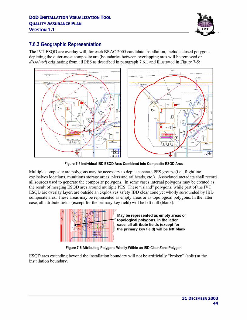
DOD INSTALLATION VISUALIZATION TOOL QUALITY ASSURANCE PLAN VERSION 1.1
7.6.3 Geographic Representation The IVT ESQD arc overlay will, for each BRAC 2005 candidate installation, include closed polygons depicting the outer-most composite arc (boundaries between overlapping arcs will be removed or dissolved) originating from all PES as described in paragraph 7.6.1 and illustrated in Figure 7-5:
Figure 7-5 Individual IBD ESQD Arcs Combined into Composite ESQD Arcs
Multiple composite arc polygons may be necessary to depict separate PES groups (i.e., flightline explosives locations, munitions storage areas, piers and railheads, etc.). Associated metadata shall record all sources used to generate the composite polygons. In some cases internal polygons may be created as the result of merging ESQD arcs around multiple PES. These “island” polygons, while part of the IVT ESQD arc overlay layer, are outside an explosives safety IBD clear zone yet wholly surrounded by IBD composite arcs. These areas may be represented as empty areas or as topological polygons. In the latter case, all attribute fields (except for the primary key field) will be left null (blank):
Figure 7-6 Attributing Polygons Wholly Within an IBD Clear Zone Polygon
ESQD arcs extending beyond the installation boundary will not be artificially “broken” (split) at the installation boundary.
31 DECEMBER 2003 44

DOD INSTALLATION VISUALIZATION TOOL QUALITY ASSURANCE PLAN VERSION 1.1
7.6.4 Valid Sources and Source Selection Criteria The following are considered valid and viable sources for ESQD arcs:
• Department of Defense Explosives Safety Board (DDESB)-approved site plans. • Service-approved waivers and exemptions—the ESQD condition waivered or exempted must also
be depicted. • Site plans awaiting formal DDESB approval (approval request submitted). • Explosives locations “grandfathered” using a previously authorized approval process.
Two or more of the above-listed sources may be combined to create composite ESQD arcs representing the outer-most (greater) distance of the arcs shown on all selected sources. For the purposes of IVT, the ESQD arcs should be combined as described in Section 7.6.3 and all sources should be recorded in the CSDGM metadata.
7.6.4.1 Recording the Selected Source in IVT Metadata The following are valid values for CSDGM metadata element 2.5.1.6, “Lineage, Source Contribution”:
“DDESB-Approved Site Plan” “Service-Approved Waiver/Exemption” “Site Plan Awaiting Formal Approval” “ESQD Arcs Grandfathered From Previous Approval Process” “N/A”, “Unknown”, and {null} are not valid values for CSDGM metadata element 2.5.1.6.
7.6.5 File Name and Attributes Explosive safety quantity distance arc shapefiles will be delivered with the following properties:
SDSFIE Entity Set: Military_Operations SDSFIE Entity Class: Military_Safety SDSFIE Entity Type: MLSFTARC
Military_Quantity_Distance_Arc_Area.SHP (IVT File Name) Object Type: Polygon Required Attributes: The MLSFTARC table contains 22 attribute fields, all of which must be included in the shapefile delivered to the IVT repository. The following attribute fields must be populated (all other fields must remain empty/null), and all attribute values entered in either upper case (capitalized) or title case (first letter capitalized) as shown:
DISTARC_ID (Primary Key) Unique numeric identifier for each ESQD arc polygon, starting with the number 1. Services may generate this unique ID in any fashion such that each map feature retains a unique value.
FEAT_DESC Value indicating the type of QD arc represented by each polygon. Valid values include: “IBD” – Inhabited building distance (IBD) arc {null} – Polygon outside ESQD arc clear zone
31 DECEMBER 2003 45

DOD INSTALLATION VISUALIZATION TOOL QUALITY ASSURANCE PLAN VERSION 1.1
SERVICE_D The Service that owns the installation. The value of this field should match the value shown in CSDGM metadata entity 1.1 and must be one of the following valid values:
“USA” “USN”
“USMC” “USAF”
SERVICE_D is a custom field, definition: character, 16, appended to the end of the SDSFIE table as the first custom field.
SERVICE_ID Service-specific installation identifier for the map feature, if any. This field may be used to record installation IDs used within the Services. IVT Coordinators within each military department may provide specific guidance for the use of this field. SERVICE_ID is a custom field, definition: character, 20, appended to the end of the SDSFIE table as the second custom field.
7.7 Floodplain – 100-Year 7.7.1 Description Services will provide the outermost extent of the 100-year floodplain within DoD installation boundaries for installations meeting BRAC Section 2687 threshold manpower criteria and associated ranges. The U.S. Army Corps of Engineers (USACE) defines a “floodplain” as the portion of any river valley that has historically been inundated by a river during floods. The Federal Emergency Management Agency (FEMA) defines a “floodplain” as the relatively flat lowland that borders a river, coastal area, lakeshore, or other low-lying area, usually dry but subject to flooding. The term "100-year flood" is a statistical designation that identifies an area that has a 1-in-100 (1%) chance, according to historical statistics, of being inundated by floodwaters in any given year.
FEMA has specific mandates within the National Flood Insurance Act of 1968, as amended, to identify flood hazards, including the geographic extent of 100-year floodplains, nationwide and to publish and update flood hazard information in support of the National Flood Insurance Program (NFIP). FEMA is required to consult with local officials in identifying flood-prone areas, and specific procedures are described in the Act for establishing proposed flood elevations resulting in the delineation of 100-year floodplain extents, based on FEMA-approved engineering techniques established by the USACE Hydrologic Engineering Center (HEC).
FEMA publishes several map products delineating the extent of 100-year flood zones nationwide, used primarily for determining flood insurance rates for non-exempt properties and land uses:
• Flood Hazard Boundary Map (FHBM) – Official map of a community where the boundaries of the flood (and other hazard) areas have been designated, including regulatory floodways.
• Flood Insurance Rate Map (FIRM) – The most widely distributed flood map product, in hardcopy/paper format. The FIRM designates Special Flood Hazard Areas (SFHAs) delineating 100-year flood zones (referred to as the “base flood” and designated as “A” Zones – Zones A, AE, AH, AR, A99 on FIRM maps), 500-year flood zones, and other flood hazard information.
31 DECEMBER 2003 46

DOD INSTALLATION VISUALIZATION TOOL QUALITY ASSURANCE PLAN VERSION 1.1
• Digital Flood Insurance Rate Map (DFIRM) – A digital FIRM , including 100-year flood zones, and registered to known real-world coordinates.
• Digital Q3 Flood Data – Digital Q3 Flood Data are developed by scanning the existing hardcopy FIRM and vectorizing (see Section 6.6) a thematic overlay of flood risks. FEMA acknowledges positional error associated with vectorizing FIRM maps into Q3 data and state that Digital Q3 maps should not be used for parcel-level determination of flood zone inundation. Digital Q3 data contain limited information from the FIRM but do show 100-year flood zones and may be used in lieu of DFIRM availability for any given area.
As Federally-owned properties are considered exempt, FEMA map products typically do not depict flood zones within DoD installations. As such, IVT coordinators are encouraged to review relevant FEMA map products and installation-generated sources to identify 100-year floodplain delineations.
7.7.1.1 Representing Flood Events Other Than the 100-Year Flood In the event that a viable source depicting 100-year floodplains cannot be identified for any given installation after a reasonable amount of searching, other floodplain delineations (500-year floodplains, “areas prone to flooding”) may be provided as an alternative if viable sources exist. However, Services must exhaust all reasonable effort to identify 100-year floodplain sources before considering alternative floodplain representations.
In the event floodplain representations other than the 100-year floodplain are provided for an installation, Services should note this in the CSDGM metadata as follows:
• CSDGM metadata element 1.1 (Citation 8.4), Data Set Title should be populated with “Floodplains - Other”;
• CSDGM metadata element 1.2.1, Description, Abstract should be populated with the following value in lieu of the value provided for 100-year floodplains in Appendix B:
“Compiled by the DoD Service to supplement BRAC decision-making by visually interpreting validated BRAC data, depicting the extent of flooding at installations meeting BRAC Section 8687 threshold criteria. {500-year floodplains, areas prone to flooding, other} are depicted for this installation in lieu of the availability of viable sources depicting 100-year floodplains.”
• The following statement should be added as the first sentence in CSDGM metadata element 2.3, Completeness Report”:
“100-year floodplains are not shown due to lack of available sources. This file depicts {500-year floodplains, areas prone to flooding, other} in lieu of the 100-year floodplain.”
• CSDGM metadata element 2.5.1.1 (Citation 8.9), Lineage, Source Citation, Other Citation Details, will be populated with the same value as that for the Completeness Report, as shown:
“100-year floodplains are not shown due to lack of available sources. This file depicts {500-year floodplains, areas prone to flooding, other} in lieu of the 100-year floodplain.”
31 DECEMBER 2003 47

DOD INSTALLATION VISUALIZATION TOOL QUALITY ASSURANCE PLAN VERSION 1.1
7.7.2 Policy and Regulations • Executive Order 11988, Floodplain Management, 36 FR 8921, 15 May 71 (Amended by
Executive Order 12148). • DODI 4715.3, Environmental Conservation Program, 3 May 96. • DODD 4700.4, Natural Resources Management Program, 24 Jan 89. • OPNAV 5090.1B, Environmental and Natural Resources Program Manual, 1 Nov 94. • Air Force Instruction 32-7064, Integrated Natural Resources Management, 1 Aug 97. • AR 200-1, Environmental Protection and Enhancement, 21 Feb 97. • AR 200-3, Natural Resources - Land, Forest and Wildlife Management, 28 Feb 95.
7.7.3 Geographic Representation The IVT 100-year floodplain overlay layer will depict one or more polygons showing the extent of the 100-year floodplain, as defined by FEMA. Floodplains will be mapped to the installation boundary at a minimum, and may extend up to one mile beyond the base boundary at discretion of the Service BRAC Office. Areas of high ground enclosed fully enclosed within a 100-year floodplain, if any, will be represented as empty areas or topological polygons. In the latter case, all attribute fields (except for the primary key field) will be left null (blank).
Ancillary map features shown on FEMA map products including, but not limited to, base flood elevation (BFE) lines, cross sections, floodways, limits of detailed study lines, flood zone labels, etc. will not be included in the IVT 100-year floodplain overlay layer; if FEMA sources (FBHM, FIRM, DFIRM, Q3 Data) are used as the source for IVT, only the 100-year flood zone polygon(s) will be extracted for use in IVT.
In the event that floodplains extend beyond the installation boundary and two different sources are used for on- and off-base floodplains, those polygons may be split at the installation boundary to separate those floodplains inside the installation property from those outside the boundary. Floodplain polygons falling outside the installation boundary will contain the attribution defined in Section 7.8.5, including INSTLN_ID and SERVICE_D.
7.7.4 Valid Sources and Source Selection Criteria The following are considered valid and viable sources for 100-year floodplain boundaries, ranked from most-preferred to least-preferred:
1. Flood Studies using FEMA-Approved Methodologies (Most Preferred) – Local flood studies performed by the installation using FEMA-approved methodologies or using information from available FEMA Flood Insurance Studies (FISs) to delineate the 100-year floodplain, with floodplains delineated on a FIRM, DFIRM, or local flood study.
2. FEMA FBHM or Digital Q3 Flood Data – In the event no FIRM, DFIRM, or local study using FEMA-approved methodologies are available, installations should consider availability of FEMA-approved FBHMs or Digital Q3 Flood Data depicting 100-year floodplains for the DoD installation or activity.
31 DECEMBER 2003 48

DOD INSTALLATION VISUALIZATION TOOL QUALITY ASSURANCE PLAN VERSION 1.1
3. Installation-Generated Flood Studies or Products using Non-FEMA Approved Methodologies – Local flood studies performed by the installation using hydraulic analysis and delineation methodologies other than those approved by FEMA, or digital floodplain map products generated from automated GIS applications.
4. Notional Floodplain Boundary (Least Preferred) – An electronic drawing, only loosely based on coordinates showing the widely accepted floodplain boundary to the best of the ‘drafter’s’ ability. Typically, notional floodplain boundaries show the overall areas of flood inundation potential but were not generated using any defined engineering methodology.
The most recently published installation General Plans, Comprehensive Plans, or Master Plans should be considered viable sources for items (2), (4), and (5) above.
7.7.4.1 Recording the Selected Source in IVT Metadata The following are valid values for CSDGM metadata element 2.5.1.6, “Lineage, Source Contribution”:
“FEMA FIRM” “FEMA DFIRM” “Installation Study Using FEMA-Approved Methods” “FEMA FBHM” “FEMA Digital Q3 Flood Data” “Installation Study Using Non-FEMA Approved Methods” “Notional Floodplain Boundary” “N/A”, “Unknown”, and {null} are not valid values for CSDGM metadata element 2.5.1.6.
7.7.5 File Name and Attributes 100-year floodplain shapefiles will be delivered with the following properties:
SDSFIE Entity Set: Hydrography SDSFIE Entity Class: Hydrography_Floodplain SDSFIE Entity Type: HYFLPFLZ
Flood_Zone_Area.SHP (IVT File Name) Object Type: Polygon Required Attributes: The HYFLPFLZ table contains 38 attribute fields, all of which must be included in the shapefile delivered to the IVT repository. The following attribute fields must be populated (all other fields must remain empty/null), and all attribute values entered in either upper case (capitalized) or title case (first letter capitalized) as shown:
FLD_ZON_ID (Primary Key) Unique identifier for each flood zone polygon, starting with the number 1. Services may generate this unique ID in any fashion such that each map feature retains a unique value.
FLD_ZONE_D Flood Zone Name Code: A code indicating the type of the flood zone identified. Must be one of the following valid values: “100_YEAR” {null}
31 DECEMBER 2003 49

DOD INSTALLATION VISUALIZATION TOOL QUALITY ASSURANCE PLAN VERSION 1.1
(FLD_ZONE_D will be left blank/null for any polygons representing high ground wholly within a 100-year flood zone) In the event polygons depict flood events other than the 100-year flood as described in Section 7.7.1.1, FLD_ZONE_D must be one of the following valid values: “500_YEAR” “GENERAL” {Other} - as appropriate; e.g., “AREAS PRONE TO FLOODING”
SERVICE_D The Service that owns the installation. The value of this field should match the value shown in CSDGM metadata entity 1.1 and must be one of the following valid values:
“USA” “USN”
“USMC” “USAF”
SERVICE_D is a custom field, definition: character, 16, appended to the end of the SDSFIE table as the first custom field.
SERVICE_ID Service-specific installation identifier for the map feature, if any. This field may be used to record installation IDs used within the Services. IVT Coordinators within each military department may provide specific guidance for the use of this field. SERVICE_ID is a custom field, definition: character, 20, appended to the end of the SDSFIE table as the second custom field.
7.8 Wetlands 7.8.1 Description Services will provide the outermost extent of wetlands within DoD installation boundaries for installations meeting BRAC Section 2687 threshold manpower criteria and associated ranges. In general terms, wetlands are lands on which water covers the soil or is present either at or near the surface of the soil or within the root zone, all year or for varying periods of time during the year. The recurrent or prolonged presence of water (hydrology) at or near the soil surface is the dominant factor determining the nature of soil development and the types of plant and animal communities living in the soil and on its surface.
The Federal regulations implementing Section 404 of the 1972 Clean Water Act define wetlands as “those areas that are inundated or saturated by surface or ground water (hydrology) at a frequency and duration sufficient to support, and that under normal circumstances do support, a prevalence of vegetation (hydrophytes) typically adapted for life in saturated soil conditions (hydric soils). Wetlands generally include swamps, marshes, bogs, and similar areas.”12 The U.S. Army Corps of Engineers prepared a Wetlands Delineation Manual in 1997 providing instructions for wetlands delineation in accordance with Section 404 of the Clean Water Act.
12 40 CFR 232.2(r)
31 DECEMBER 2003 50

DOD INSTALLATION VISUALIZATION TOOL QUALITY ASSURANCE PLAN VERSION 1.1
Jurisdictional wetlands are those that are regulated by the U.S. Army Corps of Engineers under Section 404 of the Clean Water Act and must exhibit the three following characteristics: hydrology, hydrophytes, and hydric soils as per the 1987 USACE Wetlands Delineation Manual. Some areas that function as wetlands ecologically, but exhibit only one or two of the three characteristics, do not currently qualify as USACE jurisdictional wetlands. Thus activities in these wetlands are not regulated under the Section 404 program, but may still represent constraints or require careful consideration as to restrictions to development.
7.8.2 Policy and Regulations • Executive Order 11990, Protection of Wetlands, 24 May 77 • 33 USC 1251, Clean Water Act, 27 Dec 77 • 40 CFR 232, 404 Program Definitions, Exempt Activities Not Requiring 404 Permits • DODI 4715.3, Environmental Conservation Program, 3 May 96 • DODD 4700.4, Natural Resources Management Program, 24 Jan 89 • OPNAV 5090.1B, Environmental and Natural Resources Program Manual, 1 Nov 94 • U.S. Army Corps of Engineers, Technical Report Y-87-1: Wetlands Delineation Manual, Jan 87 • Air Force Instruction 32-7064, Integrated Natural Resources Management, 1 Aug 97 • AR 200-1, Environmental Protection and Enhancement, 21 Feb 97. • AR 200-3, Natural Resources – Land, Forest, and Wildlife Management, 28 Feb 95
7.8.3 Geographic Representation The IVT Wetlands overlay layer will include polygons depicting the extent of wetlands (delineated using any number of different wetlands definitions and classification systems) up to the extent of the installation boundary, and may extend up to one mile beyond the base boundary at discretion of the Service BRAC Office. Specific wetlands categories will not be depicted in the IVT Wetlands overlay layer; individual boundaries between specific wetlands areas will be dissolved (removed). Non-wetland areas wholly enclosed within a wetland polygon, if any, will be represented as empty areas or topological polygons. In the latter case, all attribute fields (except for the primary key field) will be left null (blank).
In the event that wetlands extend beyond the installation boundary and two different sources are used for on- and off-base wetlands, those polygons shall be split at the installation boundary to separate those wetlands inside the installation property from those outside the boundary. Wetland polygons falling outside the installation boundary will contain the attribution defined in Section 7.8.5, including INSTLN_ID and SERVICE_D.
7.8.4 Valid Sources and Source Selection Criteria The following are considered valid and viable sources for wetlands, ranked from most-preferred to least-preferred:
1. Installation Jurisdictional Wetland Delineation (most preferred) – Usually performed by a private consulting firm or DoD civilian wetland biologist, these wetland boundaries will have been based on field surveys and determined using the methodology established and described in the USACE Technical Report Y-87-1: Wetlands Delineation Manual, Jan 87. Establishment of a jurisdictional wetland would typically include a description of the wetland, its characteristics, and its classification methodology according to the most current techniques and standards.
31 DECEMBER 2003 51

DOD INSTALLATION VISUALIZATION TOOL QUALITY ASSURANCE PLAN VERSION 1.1
2. Installation Wetlands Mapping – An installation may have surveyed, developed, and derived wetlands boundaries located within the installation boundary, however due to funding or level-of-effort involved may not have as yet delineated wetlands as per the Jan 87 USACE methodology. These wetland boundaries would typically be based on field surveys with mapping developed by a DoD natural resources specialist supporting the installation and delineated using classification methodologies established by the USEPA, U.S. Fish and Wildlife Service (USFWS), or other organization. These wetland boundaries would not represent a jurisdictional delineation of the wetland boundary, however this mapping is considered fairly accurate and typically includes the description of the wetland, its characteristics, and its classification methodology according to the most current techniques and standards.
3. DoD Service-Wide Wetland Map Products – A DoD-component Service has developed digital maps showing wetlands boundaries at multiple (or all) installations. These mapping efforts may or may not have performed jurisdictional delineation as part of their field surveys, and therefore may not be considered legal wetland boundaries, however these boundaries may be the most accurate and useful for planning purposes. The wetlands boundaries thus developed comprise a gathering of information, such as orthophotographic imagery, and involved analysis as digital feature extraction and compilation, and development was validated by a cognizant Natural Resources Program Specialist overseeing the project, typically a biologist. Establishment of the wetland boundaries would typically include description of the wetland characteristics and classification according to most current standards. Quality assurance was completed both by the mapping contractor and by Military Wetlands Mapping Program personnel.
As an example, the Department of the Navy conducted a wetlands delineation study between 1990-1998 through the National Wetlands Inventory Center of the USFWS for most of the DoN’s major installations. Mapping was funded by the NAVFAC Environmental Directorate using the Cowardin classification system.
4. National Wetland Inventory (NWI) – Nationwide wetlands map database covering most of the United States at various map scales, produced by the USFWS. As of 1 Aug 03, NWI has produced wetlands maps of approximately 90% of the United States, of which approximately 40% have been converted to digital map format. NWI wetlands are delineated using methodologies defined by Cowardin, et. al., 1979. NOTE: Wetlands delineated via the NWI are not categorized as “jurisdictional” or “non-jurisdictional”.
5. Notional Wetland Boundary (least preferred) – A drawing, in hardcopy or digital format, only loosely based on coordinates, showing to the best of the “drafters” ability, the widely accepted wetland boundaries located on the DoD installation, or facility. Typically notional wetland boundaries show the overall layout within the installation but are not used as a legal instrument for boundary determination and are typically not based on legally accepted data sources or classification methodologies.
7.8.4.1 Recording the Selected Source in IVT Metadata The following are valid values for CSDGM element 2.5.1.6, “Lineage, Source Contribution”:
“Jurisdictional Wetland Boundary” “Installation Wetlands Mapping” “DoD Service-Wide Wetland Maps” “National Wetlands Inventory”
31 DECEMBER 2003 52

DOD INSTALLATION VISUALIZATION TOOL QUALITY ASSURANCE PLAN VERSION 1.1
“Notional Wetland Boundary” “N/A”, “Unknown”, and {null} are not valid values for CSDGM metadata element 2.5.1.6.
7.8.5 File Name and Attributes Wetland shapefiles will be delivered with the following properties:
SDSFIE Entity Set: Hydrography SDSFIE Entity Class: Hydrography_Wetland SDSFIE Entity Type: HYWETLND
Wetland_Area.SHP (IVT File Name) Object Type: Polygon Required Attributes: The HYWETLND table contains 45 attribute fields, all of which must be included in the shapefile delivered to the IVT repository. The following attribute fields must be populated (all other fields must remain empty/null), and all attribute values entered in either upper case (capitalized) or title case (first letter capitalized) as shown:
WETLAND_ID (Primary Key) Unique identifier for each wetland polygon, starting with the number 1. Services may generate this unique ID in any fashion such that each map feature retains a unique value.
WETLN_DESC Description indicating whether the polygon is in our out of a wetland area. Must be one of the following valid values (“UNKNOWN” is not a valid value):
“WETLAND” {null}
(WETLAND_DESC will be left blank/null for any polygons representing non-wetland areas wholly contained within a wetland polygon)
SERVICE_D The Service that owns the installation. The value of this field should
match the value shown in CSDGM metadata entity 1.1 and must be one of the following valid values:
“USA” “USN”
“USMC” “USAF”
SERVICE_D is a custom field, definition: character, 16, appended to the end of the SDSFIE table as the first custom field.
SERVICE_ID Service-specific installation identifier for the map feature, if any. This field may be used to record installation IDs used within the Services. IVT Coordinators within each military department may provide specific guidance for the use of this field. SERVICE_ID is a custom field, definition: character, 20, appended to the end of the SDSFIE table as the second custom field.
31 DECEMBER 2003 53

DOD INSTALLATION VISUALIZATION TOOL QUALITY ASSURANCE PLAN VERSION 1.1
7.9 Range Complex Airspace 7.9.1 Description The IVT Range Complex Airspace theme will enable visualization of operational interdependencies on and between DoD installations and air-to-ground ranges. Additionally, certain pollutants are released into the atmosphere by the DoD during normal and training operations. The presence of an installation or range in a designated pollutant nonattainment area may limit the operations that can be conducted at that facility. The following overlays will be included in the Range Complex Airspace theme:
• Special Use Airspace - Congress has given the Federal Aviation Administration (FAA) the responsibility for managing the airspace of the United States and its territories. The DoD coordinates its airspace needs with the FAA, resulting in Special Use Airspace (SUA) and Military Training Routes. SUA is an airspace designation that alerts users to areas of unusual flight hazards such as military training and operations and separates that activity to enhance safety. SUAs include warning, alert, restricted, military operation areas, and prohibited airspace over DoD ranges and other significant areas. SUAs are represented by areas on the surface of the earth wherein activities must be confined because of their nature and/or wherein limitations may be imposed upon aircraft operations that are not a part of those activities. NGA has exercised cartographic license in some cases to ensure closure of polygons as necessary.
• Military Training Routes - The Military Training Route (MTR) program is a joint venture by the FAA and the DoD to develop dedicated MTRs for the purpose of conducting low-altitude, high-speed training. MTRs are routes used by the DoD and associated Reserve and Air Guard units for the purpose of conducting low altitude navigation and tactical training in both IFR and VFR weather conditions below 10,000 feet AMSL at airspeed in excess of 250 knots. Although the MTR structure is intended for operations below 10,000 feet MSL, route segments may be defined at higher altitudes. Slow speed low altitude training routes are conducted at or below 1500 feet AGL at airspeeds of 250 knots or less.
Figure 7-7 Special Use Airspace and Military Training Routes Overlaying DoD Ranges (Shaded Orange)
31 DECEMBER 2003 54

DOD INSTALLATION VISUALIZATION TOOL QUALITY ASSURANCE PLAN VERSION 1.1
• Air Refueling Tracks - Air Refueling tracks are specific areas coordinated with the FAA where the DoD normally refuels aircraft involved in training:
Figure 7-8 Air Refueling Tracks in the Vicinity of the Nevada and Utah Test and Training Ranges
• Nonattainment Areas - Nonattainment areas are designated counties in the United States where air pollution levels persistently exceed the National Ambient Air Quality Standards (NAAQS) established by the U.S. Environmental Protection Agency (EPA). EPA uses six "criteria pollutants" as indicators of air quality and has established the NAAQS defining for each a maximum concentration above which adverse effects on human health may occur. Nonattainment pollutants consist of ozone, carbon monoxide, nitrogen dioxide, sulfur dioxide, particulate matter, and lead. Nonattainment area designations are updated on an annual basis by the EPA; nonattainment status up to 1 Jan 04 will be portrayed in IVT by shading those counties with nonattainment status, as shown below:
Figure 7-9 Counties with Carbon Monoxide Nonattainment Status in 2002 (Shaded Blue)
31 DECEMBER 2003 55

DOD INSTALLATION VISUALIZATION TOOL QUALITY ASSURANCE PLAN VERSION 1.1
Data for the IVT Range Complex Airspace theme will be compiled by the OSD IVT Office as these data are not associated with specific Services or installation. Services and installations are not required to provide Range Complex Airspace data in their IVT portfolios.
7.9.2 Policy and Regulations • 40 CFR Part 81, Designation of Areas for Air Quality Planning Purposes • 42 USC 7401, Clean Air Act, 1970 • See Section 7.3.2 for additional range complex policy and regulations
7.9.3 Geographic Representation SUA, MTR, and Air Refueling Tracks are published as “seamless” worldwide data sets. As such, these data will be made available in IVT on a nationwide rather than an installation-by-installation basis (all other IVT overlay layers and imagery are provided on an installation-by-installation basis). SUA, MTR, and Air Refueling Tracks will be provided for the CONUS AOR, Alaska, Hawaii, Puerto Rico, Guam, and near-shore territorial waters.
Non-attainment areas will be portrayed in IVT by providing a map of counties nationwide and enabling the ability to shade those counties exceeding NAAQS for the six identified pollutants on any given year, as shown in Figure 7-9.
7.9.4 Valid Sources and Source Selection Criteria SUA, MTR, and Air Refueling Tracks will be acquired by the OSD IVT Office from the NGA. The NGA Aeronautical Safety Division, has the responsibility for generating maps showing current SUA and MTR locations and status to support military aviation operations. NGA publishes several products depicting current MTRs and SUAs, including paper Flight Information Publications (FLIP) and the Digital Aeronautical Flight Information File (DAFIF), the latter will be the source for IVT. DAFIF publication is based on the International Civil Aviation Organization (ICAO) Aeronautical Regulation and Control (AIRAC) cycle of every 28 days. MTR, SUA, and Air Refueling Tracks current as of 1 Apr 03 will be included in IVT.
The EPA publishes non-attainment areas on an annual basis in 40 CFR Part 81, Subpart C - Section 107, Attainment Status Designations. The OSD IVT Office will correlate information published in this source with a map of U.S. counties from the United States Geological Survey (USGS) National Map, thereby facilitating nonattainment area display capabilities.
7.9.5 File Name and Attributes SUA, MTR, and Air Refueling Tracks will be organized using native DAFIF file names, attribute tables, and attribute values as published by the NGA. Detailed specifications can be found on the NGA web site at https://164.214.2.62/products/digitalaero/index.cfm (click ‘Specs/Data Dictionary’). The following summarizes key attributes and display characteristics of SUA, MTR, and Air Refueling Tracks in IVT:
31 DECEMBER 2003 56

DOD INSTALLATION VISUALIZATION TOOL QUALITY ASSURANCE PLAN VERSION 1.1
7.9.5.1 Special Use Airspace Two separate SUA layers are provided in DAFIF - low altitude SUA below 18,000 ft MSL and high altitude SUA above 18,000 ft MSL. Both layers utilize the same attribute table structures but have different file names:
AVDAFIF File Name: SUAS_LP (low altitude); SUAS_HP (high altitude) Object Type: Polygon Attributes:
SUAS_IDENT The official designator as assigned to the special use airspace by the host nation.
SECTOR When a special use airspace is divided into sub-units, the name of each individual section of the special use airspace. Otherwise, left blank.
TYPE The type of special use airspace. Valid values include: “A” - Alert “D” - Danger “M” - Military Operations Area “P” - Prohibited “T” - Temporary Reserved Airspace “W” - Warning
NAME The official name assigned to the specific special use airspace by the controlling authority.
ICAO International Civil Aviation Organization (ICAO) location identifier. CON_AGENCY The office of responsibility for controlling air traffic within an airspace
area of defined horizontal and vertical dimensions. LOC_HDATUM The horizontal datum determined to be used as basis for the geographic
coordinates within a given special use airspace. Typically, but not always, the same as the WGS_DATUM in CONUS.
WGS_DATUM The reference datum for the geodetic coordinates. Valid values include: “WGE” - World Geodetic System (WGS) 1984 “WGX” - Global positioning system (GPS)
COMM_NAME The call sign of the communications facilities other than the name of the referenced special use airspace or controlling agency or authority.
FREQ1 The appropriate frequency(ies) which will allow communication with the identified facility. This field will not have any implied decimal and it will contain the unit of measurement in Kilohertz (K) or Megahertz (M).
FREQ2 Same as FREQ1. LEVEL The airspace structure in which the special use airspace is effective.
Valid values include: “H” - high level airspace “L” - low level airspace “B” - both high and low level airspace
31 DECEMBER 2003 57

DOD INSTALLATION VISUALIZATION TOOL QUALITY ASSURANCE PLAN VERSION 1.1
UPPER_ALT The highest altitude (ceiling) above mean sea level (AMSL) or above ground level (AGL) in feet for the upper vertical limit of the given airspace.
LOWER_ALT The lowest altitude (floor) above mean sea level (AMSL) or above ground level (AGL) in feet for the lower vertical limit of the given airspace.
EFF_TIMES The days, hours and dates that the given airspace is to be in effect. WX Meteorological conditions in which the airspace can be used. Valid
values include: “VFR” - visual flight rules “IFR” - instrument flight rules “VMC” - visual meteorological rules “IMC” - instrument meteorological rules “NOTAM” - notice to airmen
CYCLE_DATE Identifies the calendar period in which the record was added to the file or last revised. The first two digits indicate the century followed by two digit year, the last two digits indicate the 28 day cycle in which the addition/change was made.
EFF_DATE The effective date of the special use airspace as established by the country or the date of the area planning book or PCN in which the special use airspace first appears.
7.9.5.2 Military Training Routes AVDAFIF File Name: MTRPAR Object Type: Line (oriented in flight direction) Attributes:
MTR_IDENT Unique designation of a military training route. The first two characters of identifier indicate type of route:
“IR” - Instrument route “VR” - Visual route “SR” - Slow route
ORIG_ACT The military unit designated as the originating activity including unit name, address and phone numbers.
SCH_ACT The military unit designated as the scheduling activity including unit name, address and phone numbers. Same as the ORIG_ACT in many cases.
ICAO_REGN First two letters of International Civil Aviation Organization (ICAO) location identifiers.
CTRY Two letter country identification as designated by FIPS Pub 10-X. LOC_HDATUM The horizontal datum determined to be used as basis for the geographic
coordinates within a given military training route. Typically, but not
31 DECEMBER 2003 58

DOD INSTALLATION VISUALIZATION TOOL QUALITY ASSURANCE PLAN VERSION 1.1
always, the same as the WGS_DATUM in CONUS. WGS_DATUM The reference datum for the geodetic coordinates. Valid values include:
“WGE” - World Geodetic System (WGS) 1984 “WGX” - Global positioning system (GPS)
EFF_TIMES The days, hours and dates that the given MTR is to be in effect. CYCLE_DATE Identifies the calendar period in which the record was added to the file
or last revised. The first two digits indicate the century followed by two digit year, the last two digits indicate the 28 day cycle in which the addition/change was made.
MTR_TYPE Type of military training route. Valid values include: “Instrument Route” “Visual Route” “Slow Route”
7.9.5.3 Air Refueling Tracks AVDAFIF File Name: ARFLN Object Type: Line Attributes:
ARF_IDENT The name or series of characters with which the aerial refueling operations are identified.
DIRECTION A code indicating predominant direction of the refueling track or anchor at the point of entry, if any. Otherwise, left blank. Valid values include:
“N” - North “S” - South “E” - East “W” - West
“NE” - Northeast “NW” - Northwest “SE” - Southeast “SW” - Southwest
7.9.5.4 Nonattainment Areas This overlay layer is created by attributing a map of counties from the National Map with a list of years each county exceeded NAAQS for a given criteria pollutant. One file will be provided for each of the six EPA criteria pollutants. Key attributes include the following:
File Name: Varies for each criteria pollutant. Values include: “SO” - Counties exceeding NAAQS for sulfur dioxide. “PM10” - Counties exceeding NAAQS for particulate matter. “OZONE” - Counties exceeding NAAQS for ozone. “NO2” - Counties exceeding NAAQS for nitrogen dioxide. “LEAD” - Counties exceeding NAAQS for lead. “CO” - Counties exceeding NAAQS for carbon monoxide.
Object Type: Polygon
31 DECEMBER 2003 59

DOD INSTALLATION VISUALIZATION TOOL QUALITY ASSURANCE PLAN VERSION 1.1
Attributes: NAME County name.
STATE_NAME Name of state within which the county lies. ST_FIPS Federal Information Processing System (FIPS) code for the state.
CNTY_FIPS FIPS code for the county YEARS The two-digit years in which the county achieved nonattainment status
for the given criteria pollutant. If the county achieved nonattainment status in more than one year, all years are listed, in chronological order, separated by a single space. For example, if a county achieved nonattainment status in 1998, 1999, 2002, and 2003, the value for the YEARS column would be:
98 99 02 03 CLASS2 A summary of the nonattainment status for the county, as defined by the
EPA, where necessary. Refer to the EPA nonattainment status results for specific explanations for status summaries.
PARTIAL Indication of whether or not the entire county or a portion of the county is in violation of the NAAQS. Valid values include:
“W” - Whole county in violation “P” - Part of the county in violation
In the event only a portion of the county is in violation, the entire county will be shaded as nonattainment in IVT. Even though only a portion of the county is responsible for the NAAQS violation, the NAAQS apply on a county-wide basis. Therefore, even if a portion of the county is contributing to the violation, DoD must consider that the entire county cannot accommodate additional pollutant loads. More specific descriptions of the geographic extents of partial county violations are provided in 40 CFR Part 81.
8.0 Quality Assurance and Internal Controls The IVT internal control plan (ICP) is designed to ensure consistent content across all Services and to ensure equivalency between the pictorial representation in IVT and the certified BRAC data call responses, as described in Section 6.1 for installations meeting BRAC Section 2687 threshold manpower criterion. The ICP defines data handling and certification procedures and recommends a program for validation of IVT data upon delivery to the IVT Office. The IVT ICP defines:
• Processes for preparing IVT data and performing quality assurance and quality control (QA/QC) before providing to the OSD IVT Office;
• Chain of custody and IVT data handling guidelines;
• Internal controls enabling BRAC auditors to assess compliance with data handling procedures herein and to validate the accuracy of IVT data and metadata, at auditor discretion.
31 DECEMBER 2003 60

DOD INSTALLATION VISUALIZATION TOOL QUALITY ASSURANCE PLAN VERSION 1.1
8.1 Certification and Approval Section 2903(c)(5) of BRAC requires that all information used to develop and make realignment and closure recommendations be certified as accurate and complete to the best of the certifier’s knowledge and belief. However, IVT overlay layers do not require certification unless used in deliberative analysis at the discretion of the Services.
To ensure the highest quality data are provided and to ensure equivalency between pictorial representations in IVT and certified BRAC responses, IVT overlay layers, the sources used to develop those overlay layers, and the associated metadata files will be selected by mission knowledge experts and approved by the base-level command authority at each installation meeting BRAC Section 2687 threshold manpower criterion prior to submittal to the IVT Office.
IVT imagery has been certified as positionally accurate by NGA and may be used for closure analysis at the discretion of the Services. NGA certification statements and information can be found in the Nov 01 NIMA/ASAI Commercial and Civil Imagery Program: Accuracy Evaluation of IKONOS Orthorectified and Stereo Imagery Products.
8.2 IVT Data Collection and Quality Assurance/Quality Control Procedures The IVT data collection and quality assurance and quality control (QA/QC) process is designed to ensure the accuracy of IVT data and metadata. Several levels of quality QA/QC are included in the process:
• Selection of the most appropriate sources by relevant mission knowledge experts at the installation and across the military department and approval of selected sources by the base-level command authority;
• QA/QC by IVT coordinators within the Services to ensure compliance with IVT specifications;
• QA/QC by the IVT Office to ensure compliance with IVT specifications; and
• Validation of IVT data collection processes and/or IVT source validity and metadata content accuracy by BRAC auditors, at their discretion depending on how Services elect to utilize IVT in the BRAC process.
The IVT data collection and QA/QC procedures are designed to be repeatable and consistent amongst the Services and to ensure equivalency between IVT and certified BRAC data. The procedures are also designed to afford the Services the necessary flexibility in execution of details within each step, to accommodate unique organizational structure, culture, IVT contracting mechanisms, and Service BRAC Internal Control Plan, yet evaluate validity and accuracy of IVT data and metadata in a consistent fashion.
Figure 8-1 summarizes the IVT data collection and QA/QC procedures. Each step is defined in more detail herein:
31 DECEMBER 2003 61

DOD INSTALLATION VISUALIZATION TOOL QUALITY ASSURANCE PLAN VERSION 1.1
Figure 8-1 IVT Data Collection and QA/QC Process Overview
Steps (1) through (4) shall be performed for all IVT overlay layers at installations meeting BRAC Section 2687 threshold manpower criterion prior to step (5), such that a single portfolio of all relevant IVT data and metadata are provided to the base-level command authority. Since data processing and standardization may occur at a regional or central office within a Service, the specific details of steps (2) through (4) may involve multiple data transfers between an installation and a regional or central office. Regional or centralized data formatting, data content standardization, metadata creation, and IVT data portfolio creation may require the development of installation-specific approval processes. This will ensure that the base-level command authority can approve the submitted data even though regional or centralized offices processed the data to meet IVT guidelines.
Steps (7) and (8) are optional and provide a mechanism for BRAC auditors, at their discretion, to ensure that IVT data collection process controls are in place and that the Services are collecting IVT data in a consistent fashion as per the QAP guidance.
Steps (1) through (4) shall be performed by IVT coordinators within the Services, with support from base-level mapping/GIS POCs and mission knowledge experts as necessary. Mission knowledge experts are expected to take primary responsibility for steps (1) and (2), in coordination with Service IVT coordinators.
31 DECEMBER 2003 62

DOD INSTALLATION VISUALIZATION TOOL QUALITY ASSURANCE PLAN VERSION 1.1
8.2.1 Step 1: Determine Applicability of IVT Layer Mission knowledge experts, in coordination with Service IVT coordinators, shall determine whether or not a given IVT overlay layer is relevant for the installation. Perform the following to validate applicability of any given IVT layer for the installation:
1. Review most recently published base General Plan, Comprehensive Plan, Master Plan, or equivalent document. These plans will typically indicate, either directly or indirectly, the applicability of any given IVT overlay layer at the installation.
2. Validate the applicability for each IVT layer with appropriate mission knowledge experts at the installation or within the department.
In the event a given IVT overlay layer is not applicable at an installation meeting BRAC Section 2687 threshold manpower criterion, a short written statement signed by an appropriate mission knowledge expert shall be included in the IVT portfolio presented to the base-level command authority in step (5) and should cite relevant official studies or determinations.
8.2.2 Step 2: Data Source Selection Mission knowledge experts, in coordination with Service IVT coordinators, shall select the appropriate data source(s) for any given IVT overlay layer at a given installation. Section 6.2, Data Source Identification, provides guidelines for selecting the most appropriate source(s) for an IVT overlay layer. Specific sources as defined in Sections 7.2.4, 7.3.4, 7.4.4, 7.5.4, 7.6.4, 7.7.4, and 7.8.4, Valid Sources and Source Selection Criteria, should be considered first before relying on other source information not documented herein.
The organizations holding the most appropriate data source(s) will vary by IVT overlay layer, by military department, and by installation. However, as a general rule the base General Plan, Comprehensive Plan, Master Plan, or equivalent document signed by the base-level command authority should be sought as a potential source.
8.2.3 Step 3: Conversion to IVT Specifications Service IVT coordinators shall perform the following activities to ensure compliance with IVT specifications:
1. Convert all relevant content to digital geospatial format and convert data to match specifications defined in Section 5.5.2, IVT Overlay Layer Delivery Format. IVT overlay layer data files should be structured as per Section 5.3, Data Organization – SDSFIE.
2. Structure the IVT overlay data file attribute tables and populate required attributes as per Sections 7.2.5, 7.3.5, 7.4.5, 7.5.5, 7.6.5, 7.7.5, and 7.8.5, File Name and Attributes.
3. Prepare required metadata as per Section 5.4, Metadata – FGDC CSDGM and Appendix B, IVT Metadata Requirements.
4. At the discretion of the IVT coordinator, note any significant propagation of horizontal positional accuracy or content error associated with converting data to digital format, as per Section 6.6, Converting Hardcopy (Paper) Sources to Digital Geospatial Data.
31 DECEMBER 2003 63

DOD INSTALLATION VISUALIZATION TOOL QUALITY ASSURANCE PLAN VERSION 1.1
8.2.4 Step 4: Quality Assurance/Quality Control (QA/QC) Service IVT coordinators shall perform QA/QC on every IVT overlay layer to ensure compliance with IVT specifications and to ensure the highest accuracy possible for each given IVT data layer. QA/QC checks should be performed by individuals other than those primarily responsible for data and metadata compilation in steps (2) and (3). QA/QC checks may include, but are not limited to, the following:
1. Compliance with delivery specifications defined in Section 6.2, Data Source Identification;
2. Compliance with attribution requirements defined in Sections 7.2.5, 7.3.5, 7.4.5, 7.5.5, 7.6.5, 7.7.5, and 7.8.5, File Name and Attributes;
3. Metadata completed to accurately reflect completeness, horizontal positional accuracy, selected source(s), source lineage, citation, and contact information as per Appendix B;
4. Alignment with IVT imagery and other IVT overlay layers, such that no obvious visible errors are apparent (i.e., data shifted from their true location, etc.).
5. Assessment of equivalency between IVT pictorial representation and certified BRAC responses. Service IVT coordinators may calculate (or review) the total area of features (map objects) in a given IVT overlay layer data set and compare the area value to the certified value provided by the Service in the BRAC data call response. This step will require coordination with the Service BRAC office. If the area value portrayed in the IVT overlay layer is significantly different from the certified BRAC response, Service IVT coordinators are encouraged to review the sources selected for the certified BRAC responses and IVT and, if necessary and feasible, repeat steps (1) through (4) using new, more appropriate sources for the given IVT layer. Section 8.2.8 (see the “Assessing Equivalency Between Certified BRAC Data and IVT Picture” sub-section), recommends a process to perform this assessment, and may also be performed by BRAC auditors at their discretion.
8.2.5 Step 5: Approval by Base-Level Command Authority Upon completion and successful QA/QC of all relevant IVT overlay layers and associated metadata for a given installation, the data and metadata will be provided to the base-level command authority for acknowledgement and approval for use in IVT. A portfolio will be prepared containing the following items for presentation to the base-level command authority and will contain the following items:
1. Hardcopy portfolio cover letter for signature by the base-level command authority, with the following contents (a cover letter template has been provided to the Services by the OSD IVT Office):
• Standard language summarizing contents of the IVT portfolio, for acknowledgement by the base-level command authority;
• Checklist of included IVT data content (range complex boundaries may or may not be included in this checklist as described in Sections 7.3.4 and 8.2.5.2);
• If any IVT overlay layers are not applicable at a given installation, a short statement signed and dated by appropriate mission knowledge experts stating that the given IVT overlay layer is not applicable;
• Standard BRAC disclaimer as per QAP Section 8.3.1 in the letter header or footer;
31 DECEMBER 2003 64

DOD INSTALLATION VISUALIZATION TOOL QUALITY ASSURANCE PLAN VERSION 1.1
• Signature block as follows: “Contents Approved by {name, title, office symbol} Date: {dd mmm yyyy}”;
2. Printed 8.5 x 11” or 11 x 17” map of each IVT overlay layer, showing the IVT layer and, for reference, the installation or range complex boundary, including the standard BRAC disclaimer in the map margins (map templates with recommended map format and content have been provided to the Services by the OSD IVT Office);
3. Printed 8.5 x 11” or 11 x 17” map showing the aggregate IVT layers overlain for reference on the installation or range complex boundary, including the standard BRAC disclaimer in the map margins;
4. Printed copies of metadata accompanying each IVT overlay layer, including the standard BRAC disclaimer in the printout header or footer. Unpopulated metadata items should be excluded from the printed metadata if possible. Services using ESRI software to manage and print metadata may use standard ESRI and FGDC metadata style sheets provided with the ArcGIS software or may use custom style sheets as desired to format printed IVT metadata;
5. Four Read-Only CD-ROMs with the following items on each CD-ROM:
• All relevant IVT data files, organized as per QAP Sections 5.5 and 7.0. File names on the CD-ROM should match the shapefile names as provided in Section 5.5.2;
• All relevant IVT metadata files, organized as per QAP Section 5.4 and Appendix B; • Electronic copies of each printed reference map, in PDF format; • Electronic copies of each printed metadata file, in PDF format; • CD-ROM affixed with a label for signature by the base-level command authority. The label
will contain the following information: a. Title of “DoD IVT Portfolio for {installation/site name}”; b. Standard BRAC disclaimer as per QAP Section 8.3.1; c. Signature block as follows: “Contents Approved by {name, title, office symbol}
Date: {dd mmm yyyy}”.
The base-level command authority should seek inputs from mission knowledge experts at the installation and within the Service to validate the selected sources are in fact the most appropriate for release to the IVT Office.
The base-level command authority shall sign the portfolio cover letter and the affixed label on each of the three CD-ROMs. Signature by the base-level command authority is an indication that the information is true and correct to the best of his/her knowledge.
Upon signature by the base-level command authority:
• The signed portfolio cover letter will be scanned and stored in electronic format - PDF for TIFF preferred;
• The hardcopy printouts, one CD-ROM, and one electronic copy of the signed portfolio cover letter will be kept on file at the installation;
31 DECEMBER 2003 65

DOD INSTALLATION VISUALIZATION TOOL QUALITY ASSURANCE PLAN VERSION 1.1
• The remaining three CD-ROMs, with electronic copies of the signed cover letter, will be sent to the Service BRAC and/or IVT Office, in accordance with each Service’s respective BRAC Internal Control Plan. It is recommended that the MAJCOM, MACOM, or EFA/EFD retain one copy of the CD-ROM, the Service IVT Office retain another copy, and the last copy of the CD-ROM be sent to the OSD IVT Office;
• One CD-ROM, with electronic copies of the signed cover letter, will be provided to the OSD IVT Office no later than the stated IVT data delivery deadline.
The contents of IVT data and metadata may not be modified upon signature. Use of Read-only CDs (CD-ROM) will ensure no modification of data upon signature. Read-write CDs (CD-R/W) are not permitted for use.
8.2.5.1 Chain of Custody In order to ensure the approved IVT portfolio is appropriately tracked through the Services, the following general chain-of-custody is established for IVT data between steps (5) and (6):
1. The base-level command authority will approve the IVT portfolio – step (5) as described in Section 8.2.5 – and submit the portfolio in accordance with Service-specific direction as outlined in the QAP cover letter.
2. The Service’s IVT Office will record in their internally-developed tracking systems the receipt of the submittals in order to track the Service’s overall IVT progress status.
3. The Service’s IVT Office will retain one of the three CD-ROM copies of the IVT data/metadata and the accompanying cover letter in order to centrally maintain a Service-specific off-site backup of the data; address any questions posed by the OSD IVT Office, Service BRAC Offices, BRAC Auditors, or Service Undersecretaries for BRAC; and to otherwise perform support for the Service BRAC Office.
4. As the Service’s IVT coordinating element, the Service’s IVT Office will submit to the OSD IVT Office the final IVT submittal package, as prepared by the base-level command authority.
8.2.5.2 Obtaining Signature for Range Complex Boundaries In the event range complex boundaries are provided by installations, the IVT portfolio cover letter for those installations will include an entry for range complex boundaries, as described in Section 8.2.5. In the event range complex boundaries are provided to OSD by a central range office/authority as described in Section 7.3.4, a letter with signature will be provided by that central range office/authority and range complex boundaries will be omitted from the IVT portfolio cover letters provided by the installations.
8.2.6 Step 6: Acceptance by OSD IVT Office IVT coordinators within the Services will submit the IVT data and metadata on CD-ROM with affixed label containing base-level command authority signature, with signed portfolio cover sheet, to the OSD IVT Office. IVT coordinators shall send IVT data for each installation meeting BRAC Section 2687 threshold manpower criterion as the data are available; Services shall not wait to deliver data for all installations at a single time.
The submittal will include the following items:
31 DECEMBER 2003 66

DOD INSTALLATION VISUALIZATION TOOL QUALITY ASSURANCE PLAN VERSION 1.1
• Scanned copy of the signed portfolio cover page; • CD-ROM with affixed label bearing base-level command authority signature and containing each
relevant IVT overlay layer as an ESRI shapefile as per Section 5.5.2, IVT Overlay Layer Delivery Format and metadata file for each relevant IVT overlay layer as per Section 5.5.2 on CD-ROM.
IVT data and metadata will only be accepted on CD-ROM. Other transmittal methods such as EMAIL with attachments or posting on File Transfer Protocol (FTP) sites are not acceptable.
The OSD IVT Office will perform the following acceptance checks upon receipt of IVT data and metadata:
Validating submittal contents:
• Inclusion of signed portfolio cover page.
• All file names meet IVT delivery specifications.
Ensuring compliance with IVT specifications:
• Compliance with delivery specifications defined in Section 6.2, Data Source Identification;
• Compliance with attribution requirements defined in Sections 7.2.5, 7.3.5, 7.4.5, 7.5.5, 7.6.5, 7.7.5, and 7.8.5, File Name and Attributes, including ensuring that all other fields not required to be populated remain empty;
• Metadata completed to accurately reflect completeness, horizontal positional accuracy, selected source(s), source lineage, citation, and contact information as per Appendix B;
Assessing visual data quality:
• Alignment with IVT imagery and other IVT overlay layers, such that no obvious visible errors are apparent (i.e., data shifted from their true location, etc.).
8.2.7 Step 7: Random Selection for Auditor Validation (Optional) Steps (7) and (8) are optional and provide an opportunity for BRAC auditors to validate IVT data collection processes, QA/QC processes, or individual IVT data sets at their discretion depending on how their respective Services use IVT in BRAC 2005. If IVT is to be used in deliberative discussions, then BRAC auditors may use the procedures defined in Steps (7) and (8) as the basis for an IVT validation effort.
Should BRAC auditors elect to do so, a statistically significant number of installations meeting BRAC Section 2687 threshold manpower criterion may be randomly selected to ensure Services are collecting and performing necessary QA/QC on IVT data as defined herein.
BRAC auditors will share the list of randomly-selected installations with the OSD IVT Office. This list will not be shared with the Services. Upon acceptance of the IVT submittal in step (6), the OSD IVT Office will notify BRAC auditors that IVT data for the selected installation(s) are available for validation.
31 DECEMBER 2003 67

DOD INSTALLATION VISUALIZATION TOOL QUALITY ASSURANCE PLAN VERSION 1.1
8.2.8 Step 8: Auditor Validation (Optional) In the event BRAC auditors choose to validate IVT data collection processes, QA/QC processes, or individual IVT data sets, the following is a list of internal controls that auditors may use to construct an IVT validation plan. Auditor validation may include, but may not be limited to, the following internal controls. Auditors may execute these controls at the Service IVT Office or at randomly selected installations as requirements and resources warrant.
Recommended acceptable responses to each internal control question are provided in parentheses for auditor consideration:
Assessing source validity:
• Was the selected source(s) on the list of valid sources identified in the QAP? (Yes, or if not, a qualified mission knowledge expert should state that none of the valid sources listed in Section 7.0 are available)
• Was the selected source identified by a mission knowledge expert located at the base or elsewhere within the military department? Or alternately (and less preferably), was the source selected by a GIS/mapping technician? (The source should be selected by a qualified mission knowledge expert as per Sections 6.1 and 8.3.2)
• What was the justification for selecting a given source? Did the source portray the most accurate or the most current conditions at the installation? Other justification for source selection? (Source selection should be based on one or more of the criteria listed in Section 6.1, as stated by a qualified mission knowledge expert)
Assessing metadata completeness:
• Has the metadata file been completed (i.e., are all required CSDGM metadata elements populated, and are those elements populated with valid values as per the QAP?) (Yes)
• Who authored the metadata file? (The POC responsible for authoring the metadata file should be identifiable by either the Service IVT Office or the installation)
• Contact the mission knowledge expert identified in the metadata file, and validate the source lineage information provided. (Mission knowledge experts should be able to identify and present, if necessary, the selected source(s) for each IVT overlay layer)
Assessing IVT data accuracy:
• Physically review any or all of the sources considered, to be provided by the relevant mission knowledge expert, and based on source selection criteria defined in Section 6.2, Data Source Identification, select what the auditor sees as the most appropriate source. Does this source match the source selected by the Service? (Auditors should select the same source as the qualified mission knowledge expert, based on selection criteria presented in Section 6.1)
• Was the methodology used to delineate conditions on the selected source approved by Federal and/or DoD policy and regulations? (Yes)
• For hardcopy/paper maps converted to digital format:
31 DECEMBER 2003 68

DOD INSTALLATION VISUALIZATION TOOL QUALITY ASSURANCE PLAN VERSION 1.1
o At what scale was the information drafted, or what was the stated scale for the published source map? (The original map scale should be known and reportable)
o Does the hardcopy/paper source map meet NMAS at a stated map scale? (Preferably yes) o What methodology was used to convert the content from the hardcopy/paper map to
digital format (options outlined in Section 6.6, Converting Hardcopy (Paper) Maps to Digital Geospatial Format)? (Conversion methodology should be known and reportable, as per Section 6.6 definitions)
o Was any consideration given to the amount of error propagated during conversion to digital format, as per Section 6.6? Was the error quantified and/or recorded in the associated IVT metadata file? (Yes, in the event that significant propagation of error was anticipated by the individual(s) performing the conversion)
Assessing equivalency between certified BRAC data and IVT picture:
Several questions included in the BRAC data calls may request information on constraint factors visualized in IVT (e.g., a question about the total area of wetlands at an installation). As per Section 6.1, there is no requirement for the wetlands portrayed in IVT to exactly match the certified answer in response to the BRAC data call. Therefore, a given installation may provide a certified response indicating 105 acres of wetlands, yet the area measured from the corresponding wetlands picture in IVT may be 120 acres. However, auditors may choose to assess how closely the two values match, to ensure that there is no significant difference between the two values. The following procedure may be used to establish the amount of significant difference for any given factor at any given installation, and to assess whether the difference in values falls within that threshold:
• Buffer the polygon(s) within each IVT overlay layer to be tested by 6.67 feet (2.03 meters). This value is based on the optimal viewing scale for 1-meter resolution imagery13. Create both an inner buffer (to define the minimal area threshold value for the polygon) and an outer buffer (to define the maximum area threshold value for the polygon) as shown:
Figure 8-2 Polygon Buffers Establishing Minimum and Maximum Threshold Values for
Comparing to Certified BRAC Responses
• Calculate the area of the inner buffer to establish the minimum area threshold value and the outer buffer to establish the maximum area threshold value within which certified BRAC responses
13 The optimal viewing scale for 1-meter resolution imagery is 1:4,000 as determined by COTS mapping software from ESRI, Inc. National Map Accuracy Standards (NMAS) state that for maps on publication scales larger than (i.e., more detailed than) 1:20,000, not more than 10 percent of points tested will be in error by more than 1/50 inch, measured on the publication scale. Therefore given optimal imagery map scale, the maximum positional error is 6.67 feet, or 2.03 meters.
31 DECEMBER 2003 69

DOD INSTALLATION VISUALIZATION TOOL QUALITY ASSURANCE PLAN VERSION 1.1
should fall. For example, the calculated threshold may be a minimum area of 100 acres and a maximum area of 140 acres.
• Compile the calculated maximum and minimum areas for all features in a given IVT overlay layer for the installation, and then compare the certified BRAC response to those threshold values. If the certified answer falls outside the established threshold values, the difference between certified BRAC data and the corresponding IVT picture may be considered significant and may warrant further investigation at the discretion of BRAC auditors. In the example above, the certified wetlands area at the base was 105 acres, which falls within the threshold of 100 and 140 acres, therefore auditors may conclude the difference between the two values is insignificant.
Assessing content accuracy via ground truthing (wetlands only):
• Perform ground truthing on-site as per Section 6.5.1, Ground Truthing and Error Matrices.
Assessing horizontal positional accuracy:
• Assessment of horizontal positional accuracy requires cartography, surveying, and global positioning system (GPS) expertise and may not be suitable for BRAC auditors. However, FGDC-STD-007.1-1998, Reporting Methodology, Section 1.2, defines several methodologies for ground-truthing positional accuracy of digital geospatial data, including statistical testing, least squares adjustment, comparison with tested values of higher accuracy, repeat measurements for precision testing, and estimation.
While the purpose of the above-listed internal controls are to provide a mechanism for BRAC auditors to validate IVT data collection and QA/QC processes, auditors reserve the right to reject any selected IVT data set(s) at their discretion. In this event BRAC auditors will notify the IVT Office of problems encountered and recommended solutions, if any. The IVT Office will request the military department to revise the IVT data set(s), re-submit to the base-level command authority, and re-submit to the IVT Office.
8.2.9 Step 9: Submittal to IVT Repository Upon completion of step (6), or for installations randomly selected for auditor validation, completion of step (8), the IVT Office will load the IVT data and metadata into the IVT Repository at the Pentagon. An IVT Operational, System, and Technical Architecture document will be developed to guide development of the IVT Repository and tools.
8.3 Record Keeping 8.3.1 Disclaimers Upon signature by the base-level command authority, the IVT portfolio provided by each installation - including the portfolio cover letter and CD-ROMs - will be provided to OSD for use in support of the BRAC 2005 process and therefore shall contain the BRAC disclaimer. Other documents addressing IVT processes or portraying data from IVT, including EMAIL messages, meeting minutes, etc. may be required to include the standard BRAC disclaimers, at the discretion of the Service BRAC offices. The following standard BRAC disclaimer shall be placed on the IVT portfolio materials:
Deliberative Document - For Discussion Purposes Only Do Not Release Under FOIA
31 DECEMBER 2003 70

DOD INSTALLATION VISUALIZATION TOOL QUALITY ASSURANCE PLAN VERSION 1.1
8.3.2 IVT Portfolio for Base-Level Command Authority Signature Services should format the IVT portfolio cover letters and hard-copy reference maps, as described in Section 8.2.5, using templates provided by the IVT Program Office on 31 Dec 03. The exact format of each Services’ portfolio cover letter and maps may vary slightly from the OSD-provided templates as necessary to reflect Service-specific requirements and information..
8.3.3 Releasibility To protect the integrity of the BRAC 2005 process, all IVT data and metadata provided in the IVT portfolio are deemed deliberative and internal to DoD. Requests for release of IVT data and metadata in support of BRAC 2005, including those under the Freedom of Information Act (FOIA), received prior to the Secretary of Defense forwarding his realignment and closure recommendations to the BRAC Commission shall be forwarded to the IVT Office. The IVT Office will vet the request with the IVT IPT and BRAC Joint Cross Service Groups (JCSGs) as necessary before authorizing release of the requested data or metadata.
8.3.3.1 Audit Access to Records As per BRAC Policy Memo No. One, the DoD will allow GAO and BRAC auditors full and open access to all elements of the BRAC process, including IVT data and metadata, and to all data supporting the Secretary’s final recommendations as it is being developed and implemented. Copies of deliberative meeting minutes will be made available to the GAO as they are signed by the BRAC Chair.
BRAC auditors will be granted access to IVT information for those installations randomly selected in step (7), Random Selection for Auditor Validation, as defined in Section 8.2.7. However, to comply with BRAC Policy Memo No. One requirements, BRAC auditors may request access to IVT data or metadata at any time.
8.3.3.2 Dissemination Consistent with the organizational controls set forth in the DoD BRAC ICP in BRAC Policy Memo No. One, access to data and metadata in the installation-provided IVT portfolios will not be granted to any individual, to include technical experts or outside consultants, without the consent of the IVT Office, with coordination with the IVT IPT. Such access carries a responsibility for ensuring that IVT data and information are treated as sensitive and pre-decisional. Members of the IVT team within OSD and the Services, as defined in the IVT Charter, are required to protect the BRAC 2005 process from either improper or unofficial disclosures. The IVT team as defined in the IVT Charter must take precautions to prevent the acceptance of information that has not been certified by the base-level command authority.
IVT data and metadata, once uploaded into the IVT Repository, will be made available to the BRAC deliberation and support teams within OSD, including the Undersecretaries for BRAC and the JCSGs, and within the military department BRAC offices.
8.3.3.3 Access to IVT Data Access to IVT data, either virtually, or via obtaining physical copies, will be established in the IVT Operational, System, and Technical Architecture.
31 DECEMBER 2003 71

DOD INSTALLATION VISUALIZATION TOOL QUALITY ASSURANCE PLAN VERSION 1.1
8.3.3.4 Distribution Format When approved for release by the IVT IPT, the IVT Office will provide IVT information in the following formats:
BRAC Commission, Public Domain Internal DoD Use, BRAC Auditors
IVT Overlay Layer Non-modifiable format; hardcopy map, or unregistered picture (TIFF, JPG, GIF, PDF, etc.)
Native electronic format (ESRI shapefile), georeferenced and attributed.
IVT Imagery Non-manipulatible derived data including hardcopy maps or unregistered picture (TIFF, JPG, GIF, PDF, etc.), as per NGA DoD/Title 50 commercial imagery license restrictions
Source data in native electronic format (GeoTIFF or similar), georeferenced, as per NGA DoD/Title 50 commercial imagery license restrictions
IVT metadata Native electronic format (XML, SGML) or hardcopy printouts
Native electronic format (XML, SGML) or hardcopy printouts
Distribution of IVT imagery is constrained by NGA commercial imagery DoD/Title 50 license restrictions to Military Departments, Defense Agencies, and the Federal intelligence community as defined in Appendix C. Non-DoD organizations and the general public retain the right to purchase the same imagery directly from the vendor at their discretion. DoD/Title 50 license agreements are defined in the NGA Commercial Imagery Copyright and License Interim Guidance, 2 Aug 00. Specific license restrictions for IVT imagery and a list of Title 50 organizations can be found in Appendix C.
8.3.4 Non-Disclosure Agreements Individuals responsible for preparing, reviewing, or handling IVT data and metadata, including mission knowledge experts within the Services assisting with IVT source selection, may be asked to sign a BRAC 2005 non-disclosure agreement, at the discretion of the Service BRAC Offices. The DoD standard agreement is at Appendix C to BRAC Policy Memo No. 1.
31 DECEMBER 2003 72

DOD INSTALLATION VISUALIZATION TOOL QUALITY ASSURANCE PLAN VERSION 1.1
Appendix A - References 33 USC 1251, Clean Water Act, 27 Dec 77
40 CFR 232, 404 Program Definitions, Exempt Activities Not Requiring 404 Permits
Air Force Audit Agency (AFAA) Memorandum to SAF/IEB, Interim Memorandum – 2005 Base Realignment and Closure – Installation Visualization Tool Data Reliability (Project F2003-FB4000-0854.000), 7 Jul 03
Air Force Handbook (AFH) 32-7084, AICUZ Program Manager’s Guide, 1 Mar 99
Air Force Instruction (AFI) 13-212, Range Planning and Operations, 7 Aug 01
AFI 32-7063, Air Installation Compatible Use Zone Program, 17 Apr 02
AFI 32-7064, Integrated Natural Resources Management, 1 Aug 97
Air Force Manual (AFMAN) 91-201, U.S. Air Force Explosives Safety Standards, 18 Oct 01
Army Regulation (AR) 200-1, Environmental Noise Management Program, 21 Feb 77
AR 200-1, Environmental Protection and Enhancement, 21 Feb 97.
AR 200-3, Natural Resources – Land, Forest, and Wildlife Management, 28 Feb 95
AR 350-4, Integrated Training Area Management, 8 May 98
AR 385-64, U.S. Army Explosives Safety Program, 1 Feb 00
AR 415-28, Construction: Real Property Category Codes, 10 Oct 96
Army Technical Manual 5-803-7, Airfield and Heliport Design, 1 May 99
CADD-GIS Technology Center, Spatial Data Standards for Facilities, Infrastructure, and Environment (SDSFIE), NCITS 353, Version 2.22. Apr 03
CADD-GIS Technology Center, SDSFIE Compliance Policy, 23 Oct 02
DAIM-MD (AR 210-20), Data Standards for Computer Aided Drafting and Design (CADD), Geographic Information Systems (GIS), and Related Technologies, 16 Oct 01
Department of the Army Pamphlet (DAPAM) 200-2, Environmental Noise Management Program, Chapter 7, 17 Jan 02
DAPAM 385-64, U.S. Army Ammunition and Explosives Safety Standards, 15 Dec 99
DOD 6055.9-STD, DoD Ammunition and Explosive Safety Standards, Jul 99
Department of Defense Directive (DODD) 3200.15, Sustainment of Ranges and Operating Areas (OPAREAs), 10 Jan 03
DODD 4700.4, Natural Resources Management Program, 24 Jan 89
31 DECEMBER 2003 73

DOD INSTALLATION VISUALIZATION TOOL QUALITY ASSURANCE PLAN VERSION 1.1
DODD 4715.11, Environmental and Explosives Safety Management on Department of Defense Active and Inactive Ranges Within the United States, 17 Aug 99
Department of Defense Instruction (DODI) 4165.14, Inventory of Military Real Property, ADS(I&L)/ASD (Comp), 25 Aug 77
DODI 4165.57, Air Installation Compatible Use Zones, 8 Nov 77
DODI 4715.3, Environmental Conservation Program, 3 May 96
DoD Installation Visualization Tool Charter, Sept 24 01
Executive Order (EO) 11988, Floodplain Management, 36 FR 8921, 15 May 71 (Amended by EO 12148)
EO 11990, Protection of Wetlands, 24 May 77
EO 12906, Coordinating Geographic Data Acquisition and Access: The National Spatial Data Infrastructure (NSDI), Washington DC, Federal Register, Volume 59, Number 71. 11 Apr 94.
Federal Geographic Data Committee (FGDC) Standard 001-1998, Content Standards for Digital Geospatial Metadata (CSDGM) Version 2.
FGDC Standard 007.1-1998, Geospatial Positioning Accuracy Standards, Part 1:Reporting Methodology.
FGDC Standard 007.2-1998, Geospatial Positioning Accuracy Standards, Part 2:Geodetic Control Networks.
FGDC Standard 007.3-1998, Geospatial Positioning Accuracy Standards, Part 3: National Standard for Spatial Data Accuracy.
FGDC Standard 007.4-2002, Geospatial Positioning Accuracy Standards, Part 4: Standards for Architecture, Engineering, and Construction (A/E/C) and Facility Management.
Headquarters U.S. Air Force, Deputy Chief of Staff, Installations and Logistics, USAF GeoBase Policy Memo, 7 Oct 03
Headquarters US Marine Corps, Guidance Regarding Implementation of Geospatial Information Systems (GIS) and Related Technologies for Installation Management, 15 Apr 03
HQ Naval Facilities Engineering Command Interim Policy Guidance for CADD, GIS, and Related Technologies, 8 Dec 99
National Imagery and Mapping Agency (NIMA), Commercial and Civil Applications Project: Accuracy Evaluation of IKONOS Orthorectified and Stereo Imagery Products, NIMA/ASAI, Nov 01
NAVFAC Publication P-78, Navy Facilities Assets Procedures Manual, 30 Sep 01
NAVFAC P-80.3, Facility Planning Factor Criteria for Navy/Marine Corps Shore Stations – Safety Clearance, 1 Jan 82
NAVSEA OP-5, Ammunition and Explosives Ashore: Safety Regulations for Handling, Storing, Production, Renovation, and Shipping: Volume One, Seventh Revision, Change Two, 1 Mar 03
NIMA, Commercial Imagery Copyright and License Interim Guidance: A User’s Guide to Licensing and Handling Commercial Imagery, NIMA Commercial Imagery Program (CIP), 2 Aug 00
31 DECEMBER 2003 74

DOD INSTALLATION VISUALIZATION TOOL QUALITY ASSURANCE PLAN VERSION 1.1
Office of Management and Budget (OMB) Circular A-16, Coordination of Geographic Information and Related Spatial Data Activities, 3 Jul 01
OPNAV 5090.1B, Environmental and Natural Resources Program Manual, 1 Nov 94
OPNAVINST/MCO 11010.36B, AICUZ Program, 19 Dec 02
Secretary of Defense (SECDEF), Transformation Through Base Realignment and Closure, 15 Nov 02
Secretary of the Navy (SECNAV), DoN Policy on Digital Logistics Technical Data, 2 Nov 99
SECNAVINST 11011.40A, Inventory of Military Real Property, 25 Oct 69
Sobol, Bruce and Peyman, Linda, Methods to Specify the Accuracy of Categorical Spatial Data. U.S. Army Corps of Engineers, Engineer Research and Development Center Environmental Laboratory, 2000
Undersecretary of Defense for Acquisition, Technology, and Logistics (USD/AT&L), Transformation Through Base Realignment and Closure (BRAC 2005) Policy Memorandum One: Policy, Responsibilities and Procedures, 16 Apr 03
Undersecretary of Defense for Acquisition, Technology, and Logistics (USD/AT&L), Office of the Secretary of Defense Internal Control Plan for the 2005 Base Realignment and Closure Process, 16 Apr 03
Unified Facilities Criteria (UFC) 3-260-01, Airfield and Heliport Planning and Design, 1 Nov 01
United States Army Corps of Engineers (USACE), Waterways Experiment Station (WES) Environmental Laboratory, Technical Report Y-87-1, Corps of Engineers Wetlands Delineation Manual. Jan 87
United States Environmental Protection Agency (USEPA) QA/G-5G, Guidance for Geospatial Data Quality Assurance Project Plans, Mar 03
United States Geological Survey (USGS) Fact Sheet FS-171-99, National Map Accuracy Standards, Nov 99.
31 DECEMBER 2003 75

LLATION VISUALIZATION TOOL Y ASSURANCE PLAN
1.1
31 DECEMBER 2003 76
DOD INSTA
QUALIT
VERSION
CSDGM Element Number
CSDGM Element Name Description Valid Values
1.1 Citation 1.1
(Citation 8.1) Identification (Data Set Originator)
The name of an organization or individual that provided the data set. For IVT, this will contain the name of the service, a single space, followed by the installation/facility name. For joint facilities (e.g., a Joint Reserve Base), the host service should be identified as the originator, or if no host service exists, the facility should be identified as a Joint Reserve Base (JRB).
Service names: “USA” “USN” “USMC” “USAF” “JRB” Example values: “USA Fort Bliss” “USAF Edwards Air Force Base” “USN Naval Station Norfolk” “USMC MCAS Miramar” “JRB Willow Grove”
1.1 (Citation 8.2)
Identification (Data Set IVT Publication Date)
The date of release or current version of the file. This represents the date that a given IVT overlay layer and associated metadata file were “locked” and written to CD-ROM for approval by the base-level command authority (as described in Section 8.2).
Format: yyyymmdd Example values: “20031128” (representing 28 Nov 03)
Appendix B – IVT Metadata Requirements IVT data – imagery and overlay layers – will be documented using the FGDC CSDGM as per Section 5.4. Appendix B defines specific CSDGM metadata fields that must be populated for each IVT data set and valid values that must be used in those metadata fields. Multiple sources may be recorded in CSDGM Section 2 in the event that multiple sources were selected and used to develop any given IVT Overlay Layer. Layer-specific metadata requirements in addition to those defined in Appendix B are defined in Section 7, IVT Data Specifications.
“Unknown” is not a valid value unless otherwise noted.
Section 1 – Identification

DOD INSTALLATION VISUALIZATION TOOL QUALITY ASSURANCE PLAN VERSION 1.1
CSDGM Element Number
CSDGM Element Name Description Valid Values
1.1 (Citation 8.4)
Identification (Data Set Title)
The name by which the data set is referred. Must be one of the following valid values:
Valid values: “1-meter panchromatic image” “1-meter color image” “5-meter panchromatic image” “Installation Boundary” “Range Complex Boundary” “100-Year Floodplains”14 “Wetlands” “Accident Potential Zones” “Explosive Safety Quantity Distance Arcs” “Noise Contours”
1.2 Description
1.2.1 Description, Abstract A brief narrative of the data set. Must be one of the following valid values:
Valid values: Refer to Abstract Reference Table below.
1.2.2 Description, Purpose A summary of the intentions with which the data set was developed. Must be the following valid value:
Valid value: “Information portrayed herein enables DoD Military Departments, BRAC Joint Cross Service Groups, and the BRAC Commission to visualize installations meeting BRAC criterion. The information portrayed herein will be used to visually interpret statistical numerical information provided by Military Departments in response to BRAC data calls and provides a complementary geospatial supplement to the deliberative data and a starting point for further analysis.”
14 Or “Floodplains - Other” in the event flood events other than the 100-year flood are depicted, as described in Section 7.7.1.1.
31 DECEMBER 2003 77

DOD INSTALLATION VISUALIZATION TOOL QUALITY ASSURANCE PLAN VERSION 1.1
CSDGM Element Number
CSDGM Element Name Description Valid Values
1.3 Time Period of Content
1.3 (Citation 9.1.1)
Time Period of Content (Single Calendar Date)
The latest date to which the data content represents conditions on the ground. This field is used to capture neither the publication date of a study or of a hardcopy map nor the date the hardcopy was converted to digital format, but rather the latest date the conditions at the location were measured or derived. For hardcopy maps, if the content date is unknown, the map publication date can be used. If only the month and year are known, but not specific day within the given month, enter zeros (“0”) in the place of “dd” as shown.
Format: yyyymmdd Example values: “20020101” (representing 01 Jan 02) “20031128” (representing 28 Nov 03) “19980100” (representing Jan 98)
1.3.1 Time Period of Content, Currentness Reference
Reference for the Time Period of Content. Must be one of the following valid values:
Valid Values: “Ground condition date” “Publication date for source materials”
1.4 Status
1.4.1 Status, Progress The state of the data set. Must be the following value: Valid Value: “Complete”
1.4.2 Status, Maintenance and Update Frequency
The frequency with which changes and additions are made to the data set after the initial data set is completed. Must be the following value: NOTE: The data may be updated on a regular or frequent basis at the installation. However, as these data are provided as a snapshot at a single point in time for the purposes of BRAC 2005 visualization, the following value will be provided:
Valid Value: “N/A – Snapshot of conditions on given date provided for BRAC 2005 visualization”
31 DECEMBER 2003 78

DOD INSTALLATION VISUALIZATION TOOL QUALITY ASSURANCE PLAN VERSION 1.1
CSDGM Element Number
CSDGM Element Name Description Valid Values
1.5 Spatial Domain
1.5.1 Spatial Domain, Bounding Coordinates
The outermost limits of coverage of a data set expressed by latitude and longitude values in the order western-most (CSDGM element 1.5.1.1), eastern-most (1.5.1.2), northern-most (1.5.1.3), and southern-most (1.5.1.4). These bounding coordinates are provided to enable spatial search within the IVT application.
Valid Values: Latitude: -90.00 to 90.00 Longitude: -180.00 to 179.99
1.6 Keywords
1.6.1.1 Theme Keyword Thesaurus Must be the following valid value: Valid Value: “None”
1.6.1.2 Theme Keyword Common-use words or phrase words used to describe the subject of the data set. Required values include (additional keywords may be provided at Service discretion):
Required Keyword Values: “Installation Visualization Tool” “IVT” “BRAC 2005” {installation name} {layer name, as per CDSGM element 8.4}
1.7 Access Constraints
1.7 Access Constraints Restrictions and legal prerequisites for accessing the data set. These include any access constraints applied to assure the protection of privacy or intellectual property, and any special restrictions on obtaining the data set. Must be the following valid value:
Valid Value (for imagery): “Imagery acquired by the DoD may not be distributed to non-DoD organizations or to the public. DoD Title 50 restrictions apply. Non-DoD organizations may acquire this image directly from the commercial imagery vendor” Valid value (for IVT overlay layers): “Electronic copies of IVT Overlay Layers, in CADD or GIS format, will not be distributed within the public domain. Upon
31 DECEMBER 2003 79

DOD INSTALLATION VISUALIZATION TOOL QUALITY ASSURANCE PLAN VERSION 1.1
CSDGM Element Number
CSDGM Element Name Description Valid Values
request, the OSD IVT Office may provide unregistered pictures showing the geographic extent of phenomena portrayed in this IVT overlay layer.”
1.8 Use Constraints
1.8 Use Constraints Restrictions and legal prerequisites for using the data set after access is granted. These include constraints applied to assure the protection of privacy or intellectual property, and any special restrictions or limitations on using the data set. Must be the following value:
Valid Value: “Data used to supplement BRAC 2005 deliberations. This data set was not used for BRAC 2005 analysis. No use constraints upon release in the public domain.”
1.9 Point of Contact
The Point of Contact (POC) should be the mission knowledge expert who identified the data source, and shall not be the base-level GIS/mapping POC (unless the POC authoring the metadata file is the same person as the mission knowledge expert responsible for source selection). In the event the mission knowledge expert is a contractor, the organizational information should reflect the government office for which the contractor works, not the contractor company information. The name of the individual/organization responsible for creating the metadata file is recorded in CSDGM element 7.4, Metadata Contact.
1.9 (Citation 10.1.1)
Point of Contact (Contact Person)
Name of mission knowledge expert responsible for selecting the source for the given IVT layer
Example Values: “John Smith” “Joe Q Public”
1.9 (Citation 10.1.2)
Point of Contact (Contact Organization)
Organization name (or office symbol for military organizations) of the mission knowledge expert.
Example Values: “AF/ILE-I” (HQ USAF Installations and Logistics, Office of the Civil Engineer) “11CES” (11th Civil Engineering Squadron)
1.9 (Citation 10.3)
Point of Contact (Contact Position/Title)
Title of the mission knowledge expert. Example Values: “Civ” – Civilian “Contr” – Contractor Military titles including: “Capt”
31 DECEMBER 2003 80

DOD INSTALLATION VISUALIZATION TOOL QUALITY ASSURANCE PLAN VERSION 1.1
CSDGM Element Number
CSDGM Element Name Description Valid Values
“MSgt” “Lt Col”
1.9 (Citation 10.4.1)
Point of Contact (Address Type)
The type of address provided. Must be one of the following valid values:
Valid Values: “mailing” “physical” “mailing and physical” “po box” Other (describe)
1.9 (Citation 10.4.2)
Point of Contact (Address)
Address line for the mission knowledge expert. Example Values: “1240 Main Street” “100 Rickenbacker Avenue” “P.O. Box 100”
1.9 (Citation 10.4.3)
Point of Contact (City)
The address city for the mission knowledge expert. Example Values: “Washington” (for Washington DC) “Honolulu” “San Diego”
1.9 (Citation 10.4.4)
Point of Contact (State or Territory)
The address state or territory for the mission knowledge expert. Use accepted two-letter Postal state/territory codes for this field.
Example Values: “DC” – Washington, DC “VA” – Virginia “PR” – Puerto Rico “GU” – Guam
1.9 (Citation 10.4.5)
Point of Contact (Postal/ZIP Code)
The ZIP code for the mission knowledge expert. Nine digit ZIP codes, with dashes, preferred, but five digit zip codes will be accepted.
Example Values: “22030-1260” “80330”
1.9 (Citation 10.4.6)
Point of Contact (Country)
mission knowledge expert address country. Valid value for IVT must be the following:
Valid Value: “USA”
1.9 (Citation 10.5)
Point of Contact (Telephone Number)
mission knowledge expert Telephone number, including all applicable area codes and extensions. Commercial numbers are preferred, and should be preceded with “COMM” as shown. However, if only DSN numbers are available, enter that number here and
Example Values: COMM 123-456-7890 COMM 123-456-7890 ext: 345 DSN 123-456-7890
31 DECEMBER 2003 81

DOD INSTALLATION VISUALIZATION TOOL QUALITY ASSURANCE PLAN VERSION 1.1
CSDGM Element Number
CSDGM Element Name Description Valid Values
precede the number with “DSN” as shown: DSN 123-4567 1.9
(Citation 10.8) Point of Contact (EMAIL address)
The email address for the mission knowledge expert. Example Values: “[email protected]” “[email protected]”
Section 2 – Data Quality Information CSDGM Element
Number CSDGM Element Name Description Valid Values
2.3 Completeness Report
2.3 Completeness Report Information about omissions, selection criteria, generalizations, definitions used, and other rules to derive the data set. Use this field to record if any features (e.g., wetland polygon, floodplain polygon, APZ or ESQD clear zone, noise contour, or installation boundary element) were excluded from the data set for any reason. NOTE: It is assumed that all data will be provided for each IVT layer, unless those data are classified as SECRET or above.
If no omissions are present – Valid Value: “Complete data set” If omissions are present – Valid Value: Free text, describing any map features/elements that exist on the ground but have been omitted from the IVT data set due to classification constraints. Example Values: “Wetlands from 1999 restoration study not included because {provide justification}” “New boundary from 2003 land transfer to {jurisdiction] not shown as the boundary re-survey has not yet been performed.”
31 DECEMBER 2003 82

DOD INSTALLATION VISUALIZATION TOOL QUALITY ASSURANCE PLAN VERSION 1.1
CSDGM Element Number
CSDGM Element Name Description Valid Values
2.4 Positional Accuracy
2.4.1.1 Horizontal Positional Accuracy Report
A narrative explanation of the accuracy of the horizontal coordinate measurements. Use this field to record the horizontal positional accuracy of digital geospatial data sources and the published map scale of hardcopy/paper map sources, where known or where easily determined from the selected source materials. Valid values should be stated in one of the following three fashions: • Circular error, as defined by FGDC STD 007.3-
1998, NSSDA, (digital sources); • Meeting National Map Accuracy Standards
(NMAS) at a given printed map scale (hardcopy/paper sources);
• Free text qualifying the positional accuracy, in lieu of availability of circular error or NMAS statements on the selected sources.
The following statement may optionally be added to qualify any significant propagation of error associated with converting hardcopy/paper maps to digital format: “Error introduced upon conversion from hardcopy to digital format”
Circular Error Format: “4-meter CE 90 (1-meter imagery)” “25-meter CE 90 (5-meter imagery)” National Map Accuracy Standards: “Meets National Map Accuracy Standards at {map scale}” If the IVT overlay layer was created using “heads-up” digitizing techniques and another IVT image or overlay layer was used as reference: “Referenced to {IVT image or overlay layer name}” If horizontal positional accuracy is unknown: “Unknown”
31 DECEMBER 2003 83

DOD INSTALLATION VISUALIZATION TOOL QUALITY ASSURANCE PLAN VERSION 1.1
CSDGM Element Number
CSDGM Element Name Description Valid Values
2.5 Lineage The following section may be repeated numerous times in the event that multiple sources were selected and used to develop any given IVT overlay layer. Most metadata management applications (including ESRI ArcCatalog and the USACE CorpsMet application) can accommodate numerous source citations.
2.5.1.1 (Citation 8.1)
Lineage, Source Citation (Source Originator)
The name of the organization that developed the source of the IVT data set - either the office symbol of the government organization or the name of the contractor/firm in the event the source was prepared under contract to the government. Must be one of the following valid values:
Valid Values: {Source originator name}
2.5.1.1 (Citation 8.2)
Lineage, Source Citation (Source Publication Date)
The date when the source was published or otherwise made available for release. If only the month and year are known, but not specific day within the given month, enter zeros (“0”) in the place of “dd” as shown. Must be one of the following valid values:
Valid Values: “Unknown” “Unpublished material” {date} Date Format: yyyymmdd Example date values: “20020101” (representing 01 Jan 02) “20031128” (representing 28 Nov 03) “19980100” (representing Jan 98, where the specific day is not provided)
2.5.1.1 (Citation 8.4)
Lineage, Source Citation (Source Title)
The name by which the source of the IVT Layer is known. This could be the name of a local study, a national data set, a standard business process by which the data are generated, etc.
Valid Values: {source name} Example values: “National Wetlands Inventory” “Nellis AFB Noise Study” “FEMA Flood Insurance Study for {jurisdiction}”
31 DECEMBER 2003 84

DOD INSTALLATION VISUALIZATION TOOL QUALITY ASSURANCE PLAN VERSION 1.1
CSDGM Element Number
CSDGM Element Name Description Valid Values
2.5.1.1 (Citation 8.6)
Lineage, Source Citation (Geospatial Data Presentation Format)
The mode in which geospatial data depicted in the IVT layer were represented in the source document(s). Must be one of the following valid values:
Valid Values: “Diagram” “Map” “Model” “Profile” “Raster digital data” “Spreadsheet” “Tabular digital data” (e.g., coordinates) “vector digital data” Other (specify)
2.5.1.1 (Citation 8.9)
Lineage, Source Citation (Other Citation Details)
In the event that a source other than the most-preferred source is selected for an IVT data set (as per Sections 7.2.4.1, 7.3.4.1, 7.4.4.1, 7.5.4.1, 7.6.4.1, 7.7.4.1, and 7.8.4.1), and more preferred sources were available, a short description justifying the selection of the lesser-preferred source. May be a short free-text description.
Valid Values: Free text narrative description
2.5.1.6 Lineage, Source Contribution An indicator of which approved source for the IVT data set was used, from the list of valid and viable sources as defined herein. The purpose of this metadata reference is to indicate which approved data source was used, from the most-preferred to the least-preferred data sources defined in the QAP Sections listed herein.
Valid Values for IVT Imagery: 1-meter imagery – “Space Imaging IKONOS Precision 1-Meter” 5-meter imagery – “Space Imaging Indian Remote Sensing (IRS) Reference 5-Meter”
Valid Values for IVT Overlay Layers: Valid values vary by IVT layer type and by which source was chosen. Should be one of the valid values listed in the following QAP Sections, or may differ if another source was used: Installation Boundary – Section 7.2.4.1 Range Complex Boundary – Section 7.3.4.1 Noise Contours – Section 7.4.4.1 Accident Potential Zones – Section 7.5.4.1
31 DECEMBER 2003 85

DOD INSTALLATION VISUALIZATION TOOL QUALITY ASSURANCE PLAN VERSION 1.1
CSDGM Element Number
CSDGM Element Name Description Valid Values
ESQD Arcs – Section 7.6.4.1 100-Year Floodplains – Section 7.7.4.1 Wetlands – Section 7.8.4.1
2.5.2.1 Lineage, Process Description General description of the process used to convert the source identified in CSDGM metadata elements 2.5.1.1 and 2.5.1.6 to IVT format and delivery specifications as per Section 5.5.2. The purpose of this value is to help auditors understand the method used to convert the source to IVT specifications, and any potential error introduced, as per Sections 6.5 and 6.6. This field is free text. Metadata authors are encouraged to use one or more of the following statements when describing the source conversion process:
Recommended Values: “Converted georeferenced GIS file to IVT specifications” “Converted georeferenced CADD file to IVT specifications” “Georeferenced unregistered GIS file and converted to IVT specifications” “Georeferenced unregistered CADD file and converted to IVT specifications” “Registered digitization of hardcopy source” “Heads-up digitization of hardcopy source” “COGO data entry from source” “Scanned and vectorized source map” Other (specify)
Section 3 – Spatial Data Organization Information Not required for IVT.
31 DECEMBER 2003 86

DOD INSTALLATION VISUALIZATION TOOL QUALITY ASSURANCE PLAN VERSION 1.1
Section 4 – Spatial Reference Information CSDGM Element
Number CSDGM Element Name Description Valid Values
4.1 Horizontal Coordinate System Definition
4.1.1.3 Geographic Coordinate Units Measurement units for horizontal coordinates. Must be the following value:
Valid Value: “Meters”
4.1.2.2.1 Grid Coordinate System, Coordinate System Name
The name of the coordinate system for IVT data. Must be the following value:
Valid Value: “Universal Transverse Mercator”
4.1.2.2.2 UTM Zone Number Identifier of the UTM Zone the IVT data set falls within. Must be the following value:
Valid Value: 1 <= UTM Zone Number <= 60
4.1.4.1 Horizontal Datum Name Name of the reference system used for defining horizontal coordinates. Must be the following value:
Valid Value: “World Geodetic System of 1984 (WGS 84)”
Section 5 – Entity and Attribute Information CSDGM Element
Number CSDGM Element Name Description Valid Values
5.2 Entity and Attribute Overview
5.2.1 Entity and Attribute Overview Statement summarizing the attribute table for the IVT layer. Must be the following valid value:
Valid Value: “IVT attributes organized by the Spatial Data Standards for Facilities, Infrastructure, and Environment (SDSFIE), NCITS 353, Version 2.22. IVT attribute table structures meet basic compliance guidelines as defined by the CADD-GIS Technology Center. Several custom fields have been added to store additional information not
31 DECEMBER 2003 87

DOD INSTALLATION VISUALIZATION TOOL QUALITY ASSURANCE PLAN VERSION 1.1
CSDGM Element Number
CSDGM Element Name Description Valid Values
accommodated by the standard SDSFIE attribute tables.”
Section 6 – Distribution Information Not required for IVT. Relevant access and use constraints are described in CSDGM metadata elements 1.7, Access Constraints, and 1.8, Use Constraints.
Section 7 – Metadata Reference Information CSDGM Element
Number CSDGM Element Name Description Valid Values
7.1 Metadata Date
7.1 Metadata Date Date the metadata file was created or last updated by the Service IVT Office or other party in coordination with the Service IVT Office. Must be the following value:
Format: yyyymmdd Example values: “20040101” (representing 01 Jan 04) “20031128” (representing 28 Nov 03)
7.4 Metadata Contact The Metadata Point of Contact (POC) will be the individual responsible for authoring the metadata file. This will typically be the POC at the Service IVT Office, or other individual under supervision from the Service IVT Office. In the event the metadata author is a contractor, the organizational information should reflect the government office for which the contractor works, not the contractor company information. The mission knowledge expert responsible for source selection will be recorded in CSDGM element 1.9, Point of Contact.
7.4 (Citation 10.1.1)
Point of Contact (Contact Person)
Name of individual responsible for preparing the metadata file.
Example Values: “John Smith” “Joe Q Public”
31 DECEMBER 2003 88

DOD INSTALLATION VISUALIZATION TOOL QUALITY ASSURANCE PLAN VERSION 1.1
CSDGM Element Number
CSDGM Element Name Description Valid Values
7.4 (Citation 10.1.2)
Point of Contact (Contact Organization)
Organization name (or office symbol for military organizations) of the POC.
Example Values: “AF/ILE-I” (HQ USAF Installations and Logistics, Office of the Civil Engineer) “11CES” (11th Civil Engineering Squadron)
7.4 (Citation 10.3)
Point of Contact (Contact Position/Title)
Title of the metadata author. Example Values: “Civ” – Civilian “Contr” – Contractor Military titles including: “Capt” “MSgt” “Lt Col”
7.4 (Citation 10.4.1)
Point of Contact (Address Type)
The type of address provided. Must be one of the following valid values:
Valid Values: “mailing” “physical” “mailing and physical” “po box” Other (describe)
7.4 (Citation 10.4.2)
Point of Contact (Address)
Address line for the metadata author. Example Values: “1240 Main Street” “100 Rickenbacker Avenue” “P.O. Box 100”
7.4 (Citation 10.4.3)
Point of Contact (City)
The address city for the metadata author. Example Values: “Washington” (for Washington DC) “Honolulu” “San Diego”
7.4 (Citation 10.4.4)
Point of Contact (State or Territory)
The address state or territory for the metadata author. Use accepted two-letter Postal state/territory codes for this field.
Example Values: “DC” – Washington, DC “VA” – Virginia “PR” – Puerto Rico “GU” – Guam
31 DECEMBER 2003 89

DOD INSTALLATION VISUALIZATION TOOL QUALITY ASSURANCE PLAN VERSION 1.1
CSDGM Element Number
CSDGM Element Name Description Valid Values
7.4 (Citation 10.4.5)
Point of Contact (Postal/ZIP Code)
The ZIP code for the metadata author. Nine digit ZIP codes, with dashes, preferred, but five digit zip codes will be accepted.
Example Values: “22030-1260” “80330”
7.4 (Citation 10.4.6)
Point of Contact (Country)
Metadata author address country. Valid value for IVT must be the following:
Valid Value: “USA”
7.4 (Citation 10.5)
Point of Contact (Telephone Number)
Metadata author telephone number, including all applicable area codes and extensions. Commercial numbers are preferred, and should be preceded with “COMM” as shown. However, if only DSN numbers are available, enter that number here and precede the number with “DSN” as shown:
Example Values: COMM 123-456-7890 COMM 123-456-7890 ext: 345 DSN 123-456-7890 DSN 123-4567
7.4 (Citation 10.8)
Point of Contact (EMAIL address)
The email address for the metadata author.
Example Values: “[email protected]” “[email protected]”
7.5 Metadata Standard Name
7.5 Metadata Standard Name The name of the metadata standard used to document the data set. Must be the following value:
Valid Value: “FGDC Content Standards for Digital Geospatial Metadata”
7.6 Metadata Standard Version
7.6 Metadata Standard Version Identification of the version of the metadata standard used to document the data set. Must be one of the following values:
Valid Values: “Version 2 - 1998 (FGDC-STD-001 June 1998)” “FGDC-STD-001-1998”
31 DECEMBER 2003 90
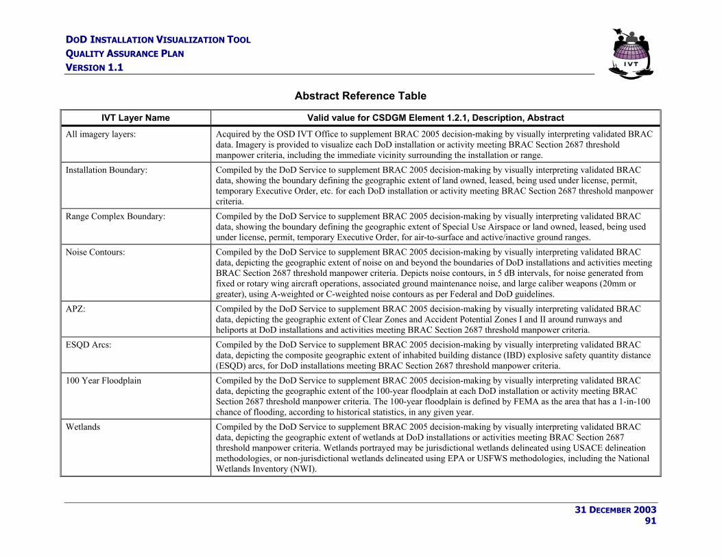
DOD INSTALLATION VISUALIZATION TOOL QUALITY ASSURANCE PLAN VERSION 1.1
Abstract Reference Table
IVT Layer Name Valid value for CSDGM Element 1.2.1, Description, Abstract All imagery layers: Acquired by the OSD IVT Office to supplement BRAC 2005 decision-making by visually interpreting validated BRAC
data. Imagery is provided to visualize each DoD installation or activity meeting BRAC Section 2687 threshold manpower criteria, including the immediate vicinity surrounding the installation or range.
Installation Boundary: Compiled by the DoD Service to supplement BRAC 2005 decision-making by visually interpreting validated BRAC data, showing the boundary defining the geographic extent of land owned, leased, being used under license, permit, temporary Executive Order, etc. for each DoD installation or activity meeting BRAC Section 2687 threshold manpower criteria.
Range Complex Boundary: Compiled by the DoD Service to supplement BRAC 2005 decision-making by visually interpreting validated BRAC data, showing the boundary defining the geographic extent of Special Use Airspace or land owned, leased, being used under license, permit, temporary Executive Order, for air-to-surface and active/inactive ground ranges.
Noise Contours: Compiled by the DoD Service to supplement BRAC 2005 decision-making by visually interpreting validated BRAC data, depicting the geographic extent of noise on and beyond the boundaries of DoD installations and activities meeting BRAC Section 2687 threshold manpower criteria. Depicts noise contours, in 5 dB intervals, for noise generated from fixed or rotary wing aircraft operations, associated ground maintenance noise, and large caliber weapons (20mm or greater), using A-weighted or C-weighted noise contours as per Federal and DoD guidelines.
APZ: Compiled by the DoD Service to supplement BRAC 2005 decision-making by visually interpreting validated BRAC data, depicting the geographic extent of Clear Zones and Accident Potential Zones I and II around runways and heliports at DoD installations and activities meeting BRAC Section 2687 threshold manpower criteria.
ESQD Arcs: Compiled by the DoD Service to supplement BRAC 2005 decision-making by visually interpreting validated BRAC data, depicting the composite geographic extent of inhabited building distance (IBD) explosive safety quantity distance (ESQD) arcs, for DoD installations meeting BRAC Section 2687 threshold manpower criteria.
100 Year Floodplain Compiled by the DoD Service to supplement BRAC 2005 decision-making by visually interpreting validated BRAC data, depicting the geographic extent of the 100-year floodplain at each DoD installation or activity meeting BRAC Section 2687 threshold manpower criteria. The 100-year floodplain is defined by FEMA as the area that has a 1-in-100 chance of flooding, according to historical statistics, in any given year.
Wetlands Compiled by the DoD Service to supplement BRAC 2005 decision-making by visually interpreting validated BRAC data, depicting the geographic extent of wetlands at DoD installations or activities meeting BRAC Section 2687 threshold manpower criteria. Wetlands portrayed may be jurisdictional wetlands delineated using USACE delineation methodologies, or non-jurisdictional wetlands delineated using EPA or USFWS methodologies, including the National Wetlands Inventory (NWI).
31 DECEMBER 2003 91

DOD INSTALLATION VISUALIZATION TOOL QUALITY ASSURANCE PLAN VERSION 1.1
Appendix C – DoD/Title 50 License Agreement for IVT Imagery DoD/Title 50 license agreements for IVT imagery are defined and a list of Title 50 organizations are included in the NIMA Commercial Imagery Copyright and License Interim Guidance, 2 Aug 00 as follows:
Space Imaging IKONOS 1-meter imagery license agreement:
IKONOS --- DoD/Title 50 & Coalition Forces Licensed Data License Agreement for IKONOS Products
Between the National Imagery and Mapping Agency (NIMA) and Space Imaging, Inc. In accordance with contract # NMA301-99-D-0002
Imagery products and all derived products are for internal Government use only, constant with the terms of the appropriate distribution license set forth below. DoD/Title 50 & Coalition Forces License This license permits distribution rights to share imagery or imagery products among DoD Agencies, Title 50 Agencies and with allies/coalition partners when working with foreign governments on joint projects or joint operations. All imagery or imagery products distributed to allies/coalition partners may be kept by the partners after completion of the joint project, however distribution to entities outside the foreign Department/Ministry of Defense is restricted. Derivative Work Applied to Above License - Entities may use derivative works in accordance with the applicable license in any geographical location. Derivative works consisting of hardcopy prints and other non-maniputable forms of products may be used for Government use, including public information, provided that NIMA uses the following legend "© [insert year of image acquisition] Space Imaging L.P." Limited Warranty and Liability. Space Imaging warrants (a) that it has sufficient ownership rights in the Product to make the Product available to Customer under the terms hereof, free from the adverse claims of third parties; and (b) that the Product will, for thirty (30) days from the date of shipment, substantially conform to Space Imaging’s specifications when used on appropriate computer hardware. The Products are complex and may contain some non-conformities, defects or errors. Space Imaging does not warrant that the Products will meet Customer’s needs or expectations, that operations of the Products will be error free or uninterrupted, or that all non-conformities can or will be corrected. THERE ARE NO EXPRESS OR IMPLIED WARRANTIES OF FITNESS OR MERCHANTABILITY GIVEN IN CONNECTION WITH THE SALE OR USE OF THIS PRODUCT. Customer must notify Space Imaging within the 30-day warranty period of any warranty claim. Space Imaging’s SOLE OBLIGATION and Customer’s SOLE REMEDY under this Limited Warranty is that Space Imaging either, in its discretion, shall: (a) use reasonable efforts to repair or replace the Product or to provide an avoidance procedure within a commercially reasonable time so that the Product substantially conforms to the specifications contained in Space Imaging’s documentation, or (b) refund the amount of the initial fee previously paid by Customer for the non-conforming Product. This Limited Warranty is void if any non-conformity has resulted from accident, abuse, misuse, misapplication, or modification by someone other than Space Imaging. The Limited Warranty is for Customer’s benefit only, and is non-transferable. Space Imaging is not liable for any incidental or consequential damages associated with Customers possession and/or use of the Product. This warranty is not applicable to the extent that any provision of this warranty is prohibited by any federal, state or local law that cannot be preempted. This warranty gives Customer specific legal rights, and Customer may also have other rights which vary from state to state.
Space Imaging IRS 5-meter imagery license agreement:
IRS-1C/1D (via Space Imaging Corp.) --- DoD/Title 50 & Coalition Forces Licensed Data License Agreement for IRS-1C/-1D Products
Between the National Imagery and Mapping Agency (NIMA) and Space Imaging, Inc. In accordance with contract # NMA301-99-D-0002
Imagery products and all derived products are for internal Government use only, constant with the terms of the appropriate distribution license set forth below. DoD/Title 50 & Coalition Forces License
31 DECEMBER 2003 92

DOD INSTALLATION VISUALIZATION TOOL QUALITY ASSURANCE PLAN VERSION 1.1
This license permits distribution rights to share imagery or imagery products among DoD Agencies, Title 50 Agencies and with allies/coalition partners when working with foreign governments on joint projects or joint operations. All imagery or imagery products distributed to allies/coalition partners may be kept by the partners after completion of the joint project, however distribution to entities outside the foreign Department/Ministry of Defense is restricted. Derivative Work Applied to Above License - Entities may use derivative works in accordance with the applicable license in any geographical location. Derivative works consisting of hardcopy prints and other non-maniputable forms of products may be used for Government use, including public information, provided that NIMA uses the following legend “ [insert year of image acquisition] ANTRIX Corporation Limited. (All Rights Reserved.)” Limited Warranty and Liability. Space Imaging warrants (a) that it has sufficient ownership rights in the Product to make the Product available to Customer under the terms hereof, free from the adverse claims of third parties; and (b) that the Product will, for thirty (30) days from the date of shipment, substantially conform to Space Imaging’s specifications when used on appropriate computer hardware. The Products are complex and may contain some non-conformities, defects or errors. Space Imaging does not warrant that the Products will meet Customer’s needs or expectations, that operations of the Products will be error free or uninterrupted, or that all non-conformities can or will be corrected. THERE ARE NO EXPRESS OR IMPLIED WARRANTIES OF FITNESS OR MERCHANTABILITY GIVEN IN CONNECTION WITH THE SALE OR USE OF THIS PRODUCT. Customer must notify Space Imaging within the 30-day warranty period of any warranty claim. Space Imaging’s SOLE OBLIGATION and Customer’s SOLE REMEDY under this Limited Warranty is that Space Imaging either, in its discretion, shall: (a) use reasonable efforts to repair or replace the Product or to provide an avoidance procedure within a commercially reasonable time so that the Product substantially conforms to the specifications contained in Space Imaging’s documentation, or (b) refund the amount of the initial fee previously paid by Customer for the non-conforming Product. This Limited Warranty is void if any non-conformity has resulted from accident, abuse, misuse, misapplication, or modification by someone other than Space Imaging. The Limited Warranty is for Customer’s benefit only, and is non-transferable. Space Imaging is not liable for any incidental or consequential damages associated with Customers possession and/or use of the Product. This warranty is not applicable to the extent that any provision of this warranty is prohibited by any federal, state or local law that cannot be preempted. This warranty gives Customer specific legal rights, and Customer may also have other rights which vary from state to state.
DoD/Title 50 applies to the Military Departments, Defense Agencies, and the intelligence community as per United States Code, Title 50 - War and National Defense, Chapter 15 - National Security, Section 401a. - Definitions, Paragraph (4). The term “intelligence community” includes –
(A) Office of the Director of Central Intelligence, which shall include the Office of the Deputy Director of Central Intelligence, the National Intelligence Council (as provided for in section 403-5(b)(3) [1] of this title), and such other offices as the Director may designate;
(B) Central Intelligence Agency; (C) National Security Agency; (D) Defense Intelligence Agency; (E) National Imagery and Mapping Agency; (F) National Reconnaissance Office; (G) Other offices within the Department of Defense for the collection of specialized national
intelligence through reconnaissance programs; (H) Intelligence elements of the Army, the Navy, the Air Force, the Marine Corps, the Federal Bureau
of Investigation, the Department of the Treasury, and the Department of Energy; (I) Bureau of Intelligence and Research of the Department of State; and (J) Such other elements of any other department or agency as may be designated by the President, or
designated jointly by the Director of Central Intelligence and the head of the department or agency concerned, as an element of the intelligence community.
31 DECEMBER 2003 93