Documenting Best Practices in Geospatial SOA: … document covers best practices in the design,...
35
2008 NSDI Cooperative Agreement Program Category 2: Best Practices in Geospatial Service Oriented Architecture (SOA) Documenting Best Practices in Geospatial SOA: Wetlands JD Analyzer Best Practices in SOA-based Geospatial Services Version 1.0 Image Matters LLC 201 Loudoun St, SW Leesburg, VA 20175 Internet Address: http://www.imagemattersllc.com July 15, 2009
Transcript of Documenting Best Practices in Geospatial SOA: … document covers best practices in the design,...
2008 NSDI Cooperative Agreement Program Category 2: Best Practices in Geospatial Service Oriented Architecture (SOA)
Documenting Best Practices in Geospatial SOA:
Wetlands JD Analyzer
Best Practices in SOA-based Geospatial Services Version 1.0
Image Matters LLC 201 Loudoun St, SW Leesburg, VA 20175
Internet Address: http://www.imagemattersllc.com
July 15, 2009

July 15, 2009 Copyright © 2009 Image Matters LLC. All Rights Reserved. i
Table of Contents 1. Document Information ................................................................................................. 1
1.1. Identification .................................................................................................................. 1 1.2. Scope .............................................................................................................................. 1 1.3. Audience ........................................................................................................................ 1 1.4. Reference Documents .................................................................................................... 1
2. Introduction .................................................................................................................. 1 2.1. Background .................................................................................................................... 1 2.2. SOA and Web Services .................................................................................................. 2 2.3. Enterprise Architecture and FEA ................................................................................... 3 2.4. FGDC CAP .................................................................................................................... 6 2.5. Case Study: EPA JD Analyzer Application ................................................................... 6
3. Architectural Selection Criteria for GIS and Geospatial Processing ........................... 7 3.1. Selection Factors for Architecture for Geospatial Processing ....................................... 7
3.1.1. Processes / Use Case Considerations ............................................................ 9 3.1.2. User Considerations ...................................................................................... 9 3.1.3. Data Considerations ...................................................................................... 9 3.1.4. Server, Licensing, and Staff Considerations ............................................... 10
3.2. An Federal Agency Example ....................................................................................... 11 4. Best Practices for Development ................................................................................. 12
4.1. System Development Life Cycle (SDLC).................................................................... 12 4.2. Other References .......................................................................................................... 15
5. Example Development Best Practices ....................................................................... 16 6. Best Practices for Installation and Configuration ...................................................... 22
6.1. Lessons learned about Geospatial Data accessed via Open Web Services .................. 22 6.2. Managing Differences among Web Feature Services .................................................. 23
7. Lessons Learned: Geospatial Services in the Cloud and in a SOA ........................... 25 Glossary of SOA Terminology ............................................................................................ 27

July 15, 2009 Copyright © 2009 Image Matters LLC. All Rights Reserved. 1
1. Document Information 1.1. Identification This document is identified as the Best Practices in SOA-based Geospatial Services: The EPA Wetlands JD Analyzer as a case study document. The production and maintenance of this document is the responsibility of Image Matters, LLC. Approval of this document is the responsibility of the persons listed in the approvals table in the front portion of this document.
1.2. Scope This document covers best practices in the design, development, and implementation of SOA-based geospatial services, and uses the EPA Wetlands JD Analyzer application (JDA) aka “Geo-Analysis Application” as a case study. Both the application and this document were developed by Image Matters, LLC.
1.3. Audience While other organizations may benefit from this document, its primary target audience is federal agencies that are planning to develop web services, with geospatial content or focus, in a SOA environment.
1.4. Reference Documents PGFSOA, 2008 Federal Chief Information Officers Council, Practical Guide to Federal Service Oriented
Architecture, Version 1.1, June 30, 2008.
2. Introduction 2.1. Background The OMB Circular No. A-16 (rev. 2002) describes the effective and economical use and management of spatial data assets in the digital environment, through the continued development of a National Spatial Data Infrastructure (NSDI), the technology, policies, standards, human resources, and related activities necessary to acquire, process, distribute, use, maintain, and preserve spatial data. Circular A-16 stipulates that federal agencies “collect, maintain, disseminate, and preserve spatial information such that the resulting data, information, or products can be readily shared with other federal agencies and non-federal users, and promote data integration between all sources” and to “allocate

July 15, 2009 Copyright © 2009 Image Matters LLC. All Rights Reserved. 2
agency resources to fulfill [these] responsibilities”. A-16 (8a(2)) also assigns lead agencies to 34 unique thematic data sets (listed in A-16, Appendix E).
To date, lead agency compliance with the mandate to “readily share” has not been perfect. This condition might be improved by agencies’ better understanding of the data dissemination options that are available. To date, the most common electronic data sharing methods that have been put into production by federal agencies are:
• mailed media (e.g., CDs) • ftp sites • HTML-based data download sites • Internet mapping and extraction/download services, e.g., “clip, zip, and ship” • interoperable web services
The last method in the list includes those standards promulgated and maintained by the Open Geospatial Consortium (OGC). While some OGC standards provide a picture of the dataset for integration into Internet maps (i.e., Web Mapping Service, WMS), only those that allow “feature-level” (i.e., Web Feature Service, WFS; or Keyhole Markup Language, KML) or “digital number-level” access (i.e., Web Coverage Service, WCS) are truly data dissemination methods. These OGC specifications allow one important advantage over the other data dissemination methods. They are amenable to service oriented architectures (SOA), and the opportunities afforded therein. However, to date, only a few agencies (e.g., United States Geological Survey) have adopted these interoperable web service interface specifications as a means for publishing their data out to other agencies and the public.
2.2. SOA and Web Services There are as many definitions of SOA as there are advocates, practitioners, and vendors of the technology and approach. Refer to the glossary in this document for a representative sampling of definitions. The Practical Guide to Federal Service Oriented Architecture [PGFSOA, 2008] adopts a broad (beyond IT) definition of SOA (“The means by which the needs of a consumer are brought together with the capabilities of a provider”) and claims it as a “business transformation paradigm”. In the IT domain, SOA is a paradigm, a way of thinking about IT infrastructure as bundled sets of software capabilities providing services directly to humans (consumers) or indirectly through interactions with other software components on other machines over networks.
A Web Service is a particular kind of software component that delivers capabilities using Internet and Web transport protcols (TCP/IP and HTTP) and widely adopted IT mechanisms for representing documents and messages with XML. It is important to
July 15, 2009 Copyright © 2009 Image Matters LLC. All Rights Reserved. 3
recognize that SOA is not achieved simply by implementing or consuming Web Services. Along the lines of “SOA-as-a-paradigm” comes this advice:
“Remember, adding Web Services interfaces to an existing architecture does not SOA make. Take the SOA term and reverse it: instead of Service-oriented architecture, say: Architecture Oriented toward Services.” (Jason Bloomberg, ZapThink, March 2005)
SOA is a way of thinking about and architecting delivery of software capabilities that support business functions and the means to make these capabilities available for multiple expected and possibly unexpected uses. Web Services are a common and standardized mechanism for accomplishing delivery of services via the Internet with a potential reach as wide as the Web.
2.3. Enterprise Architecture and FEA An Enterprise Architecture (EA) defines the business architecture of the enterprise. It is a representation of the structures and processes of an organization, depicting the "AsIs" and "ToBe", and the inter-related business, performance, service, data, and technical viewpoints of the enterprise. EA enable the organization's collective ability to understand and effectively communicate the business that it is engaged in. EA explores both the business process and the overarching business requirements for the systems that support it.
Enterprise architecting is a highly effective means to marshal enterprise assets and resources to support business needs. Driven by business goals, an EA rationalizes the steps necessary to transform existing enterprise baselines into target states that better support and empower the business and operational needs and goals of the greater organization. Enterprises are by nature complex and the interrelationships and interactions between the component parts can be quite complicated and transient. Simply gathering the full sense of an existing enterprise’s baseline extent can take years if full details are sought.
The OMB Federal Enterprise Architecture (FEA) program was commissioned to:
• Define and align Federal business functions and supporting IT via a set of common models
• Identify opportunities to re-use and re-deploy IT assets across the Federal government
• Improve effectiveness of IT spending to help yield substational cost savings and improve service delivery for citizens.

July 15, 2009 Copyright © 2009 Image Matters LLC. All Rights Reserved. 4
The FEA is a business-driven approach to defining component based architectures and is comprised of a series of reference models (RMs) that characterize different aspects of the enterprise’s IT capabilities. The FEA Reference Models are a set of interrelated views of the enterprise designed to facilitate cross-agency analysis and identification of duplicate investments, gaps, and opportunities for collaboration. They describe FEA elements in a common and consistent way.
Figure 1. The FEA Reference Models
The Performance Reference Model (PRM) seeks to improve strategic and tactical decision making by setting targets for action, and measuring the degree of transformation that might be achieved through such action. The PRM aligns and articulates a path between process inputs and consequent organizational output. In essence, the PRM provides a “line of sight” to desired results. The PRM also helps identify performance improvement opportunities that span organization structures and agency boundaries.
The Business Reference Model (BRM) holds process and methodology guidelines for identifing and describing business activities, and focuses specifically on various “lines of business” (LoB) within an agency’s functional enterprise. The BRM helps describe the organization sources and customers for the business transactions within the agency mission. IT investments are mapped to the BRM to identify collaboration opportunities.
The Service Reference Model (SRM) is the baseline for identifying agency business applications, and then aligning these activities to reusable Service Components. Each of these may then by further described by Service Domain and Service Type. These services become guidelines for establishing reusable/accessible services.
The Data Reference Model (DRM) categorizes, describes, and establishes the standards for data exchange. The DRM promotes identification and discovery of data, and helps contribute to the reuse and sharing of data across the federal government.
July 15, 2009 Copyright © 2009 Image Matters LLC. All Rights Reserved. 5
The Technical Reference Model (TRM) categorizes the products and technologies that physically enable Service delivery. A TRM is typically used to align capital investments and identify the technologies and solutions that best support business functions, mission activities and target architectures. The TRM helps ensure solutions within an agency are in compliance with industry and Federal standards, and therefore most likely to readily integrate to a multi-agency information sharing and processing environment.
While EA, in general, and FEA specifically, can provide insight into the enterprise IT portfolio, the purpose for EA initiatives must be to deliver actionable results that are aligned with the business. To be efficient, responsive and actionable, the EA process must be designed to deal with the following challenges:
• Find alternatives to heavyweight and costly methodologies. Avoid over-compliance to methodology, process orthodoxy, and heavy-handed application of EA techniques that stifle innovation, give rise to complexity and activites focused on the process and not intended outcomes.
• Deal with complexity and find the best investment opportunities within the enterprise. The EA process and tools must exist for identifying, assessing, and fully characterizing the best investment opportunities. These opportunities are usually found at operational “pain-points” and “gain-points” (candidates for business process improvements), or through new opportunities to deliver value in the marketplace through new/enhanced offerings.
• Weak problem definition. The value propositions and means for measuring value must be clear and aligned with business imperatives.
• Lack of sound business case. Every new proposed capability must have a defensible business case that clearly states the values to the organization, how it will be measured, and describes how it will be achieved.
• Lack of innovation. A process that fosters innovation from within and identifies candidate new innovations from the broader marketplace and adapts them through business analysis and modeling phases.
• Coping with change. The evolving market or political landscape are examples of how enterprises face continual forces of change that must be responded to adeptly, in a timely, and effective manner. Improvements in key enabling technologies can also suddenly change priorities concerning where to focus innovation and IT investments.
July 15, 2009 Copyright © 2009 Image Matters LLC. All Rights Reserved. 6
2.4. FGDC CAP Federal Geographic Data Committee (FGDC) is an interagency committee promoting the coordinated development, use, sharing, and dissemination of digital geospatial information resources via the NSDI. The FGDC administers the NSDI Cooperative Agreements Program (CAP), an annual program to assist the geospatial data community through funding and other resources in implementing the components of the NSDI. This program is open to State, local and Tribal governments, academia, commercial, and non-profit organizations. This program provides small seed grants to initiate sustainable on-going NSDI implementations. The program emphasizes partnerships, collaboration and the leveraging of geospatial resources in achieving its goals.
The CAP grants are typically divided into several categories. In 2008, CAP Category 2 was entitled, and designed to develop, “Best Practices in Geospatial Service Oriented Architecture (SOA).” Recognizing that the effective design and deployment of Service Oriented Architecture (SOA) using Web Services will determine the success of shared access to geospatial data and applications, CAP Category 2 grants required:
• Joint proposals from federal government and industry leaders to design, deploy, and document reusable geospatial services and applications using SOA
• Solutions that would satisfy multi-agency requirements through the modeling and deployment of business processes through related data and service components.
• Documentation of implemented best practices in order to identify and educate federal agencies on the issues of design, implementation, and application for use in future government-wide services associated with the Geospatial LoB.
2.5. Case Study: EPA JD Analyzer Application Image Matters was one of three recipients of a FGDC 2008 CAP Category 2 Grant, via a proposal entitled “Documenting Best Practices in Geospatial SOA through the Development of a Wetlands Permitting Solution.” The purpose of the project was, thus, two-fold. First, Image Matters worked in collaboration with EPA, Fish and Wildlife Service, and Army Corps of Engineers to provide Web Services and a Web application to support the "jurisdictional determination” (JD) of wetlands under Section 404 of the Clean Water Act. Four distinct services were accessed by the “Wetlands JD Analyzer” (JDA) application:
1. National Wetland Inventory (NWI) Web Feature Service (WFS),
2. USGS National Hydrological Dataset (NHD) WFS

July 15, 2009 Copyright © 2009 Image Matters LLC. All Rights Reserved. 7
3. Web Processing Service (WPS) that computes proximity between features accessed from the two WFS, and
4. WPS that intersects features accessed from the two WFS. Second, Image Matters collaborated with the FGDC and other CAP Category 2 awardees to develop best practices documentation for the development of SOA Web Services by federal agencies. Image Matters is used the Wetland Permitting project as a case study and source of material for the present document.
3. Architectural Selection Criteria for GIS and Geospatial Processing
A GIS is defined as a system of hardware, software, data, people, and procedures used to gather, store, manipulate, analyze, and output geographic information. Its ability to do spatial analysis – finding relationships between feature geometries using overlay and proximity processes – distinguishes GIS from other technologies. While this definition still holds, GIS architectures continue to evolve, with WebGIS creating the opportunity for GIS to be integrated with online mapping services, and in doing so, expanding the possibilities of where those unique spatial operations occur.
Starting with basic Internet mapping applications, and the addition of tools such as simple buffering and routing routines that manipulated backend databases, WebGIS sites now analyze geometries and attributes streaming from multiple, distributed feature services, in some cases utilizing external stand-alone services for the geospatial processing. In other cases, spatially-enabled database software (e.g., Oracle Spatial, PostGIS) handles the analysis rather than server-centric software. Project, service, or enterprise requirements can all drive the decision as to where spatial processing is performed, where geometric relationship is crunched and the attribute relationships are made. The goal of this document is to provide some guidance to in this regard, to help you decide what the best architecture is …where your processing should take place… and what software is best suited to the required task.
3.1. Selection Factors for Architecture for Geospatial Processing
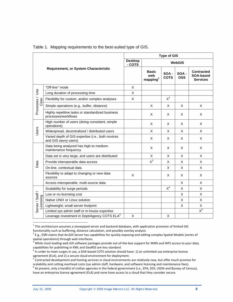
In deciding upon a particular GIS architecture and corresponding software, be it “desktop GIS” or SOA-based GIS – either commercial off-the-shelf (COTS) or open source software (OSS) there are several types of factors to be considered: those related to the process(es) to be run, the users being served, the data being processed, and other system conditions such as admin staff capabilities, and server or licensing constraints. A discussion of these factors follows, which is summarized in Table 1 (below).
July 15, 2009 Copyright © 2009 Image Matters LLC. All Rights Reserved. 8
Table 1. Mapping requirements to the best-suited type of GIS.
Requirement, or System Characteristic
Type of GIS Desktop - COTS WebGIS
Basic web
mapping1 SOA -COTS
SOA - OSS
Contracted SOA-based
Services
Pro
cess
es /
Use
C
ase
“Off-line" mode X Long duration of processing time X
Flexibility for custom, and/or complex analyses X X2
Simple operations (e.g., buffer, distance) X X X X
Highly repetitive tasks or standardized business processes/workflows X X X X
Use
rs
High number of users (doing consistent, simple operations) X X X X
Widespread, decentralized / distributed users X X X X Varied depth of GIS expertise (i.e., both novices and GIS savvy users) X X X X
Dat
a
Data being analyzed has high-to medium-maintenance frequency X X X X
Data set is very large, and users are distributed X X X X
Provide interoperable data access X3 X X X
On-line, contextual data X X X Flexibility to adapt to changing or new data sources X X X X
Access interoperable, multi-source data X X
Ser
ver /
Sta
ff /
Lice
nsin
g
Scalability for surge periods X4 X X Low or no licensing cost X X Native UNIX or Linux solution X X Lightweight; small server footprint X X Limited sys admin staff or in-house expertise X5 Leverage investment in Dept/Agency COTS ELA6 X X
1 This architecture assumes a stovepiped server and backend database, with application provision of limited GIS functionality such as buffering, distance calculation, and possibly overlay analysis 2 E.g., ESRI claims that ArcGIS Server has capabilities for quickly exposing and editing complex Spatial Models (series of spatial operations) through web interfaces. 3 While most leading web GIS software packages provide out‐of‐the‐box support for WMS and WFS access to your data, capabilities for publishing in KML and GeoRSS are less standard. 4 In order to meet surges in use, a SOA‐based COTS solution should have: 1) an unlimited‐use enterprise license agreement (ELA), and 2) a secure cloud environment for deployment. 5 Contracted development and hosting services in cloud environments are relatively new, but offer much promise for scalability and cutting overhead costs (sys admin staff, hardware, and software licensing and maintenance fees). 6 At present, only a handful of civilian agencies in the federal government (i.e., EPA, DOI, USDA and Bureau of Census), have an enterprise license agreement (ELA) and none have access to a cloud that they consider secure.

July 15, 2009 Copyright © 2009 Image Matters LLC. All Rights Reserved. 9
3.1.1. Processes / Use Case Considerations
Consideration of the nature of the analytical processes to be run and functional requirements stemming from the use case provides a clear distinction between the need for desktop GIS v. web GIS. A first question to ask is if the process or dependent application needs to be run off-line. In many emergency management applications, this is an important criterion, in which case desktop (or laptop) GIS is required. Another factor that quickly separates cases suited for desktop GIS v. SOA-base GIS is the duration of processing time. Although web processing service specifications do provide for status messaging, processes that take several hours or even days may be best left in the desktop arena, especially if the data is already on the local network. Likewise, if custom or complex operations are required, flexibility is best retained with desktop GIS. However, if only simple spatial analyses are required (e.g., buffer, distance calculation, intersection), then a WebGIS solution is possible, and is especially cost-effective if the task is highly repetitive...which brings us to considerations of the user.
3.1.2. User Considerations
As with consideration of the process, examining the target user group provides further differentiation between desktop and web GIS. If there are a large number of users doing simple, predictable/consistent operations, or even a moderate number of users doing simple, highly repetitive tasks, then a WebGIS solution can be highly cost effective. Moreover, if the user group is highly distributed, costs for separate desktop licenses can quickly mount, and a WebGIS solution should be considered.
Given the complexity of today’s desktop GIS software, the type of user should also be taken into account. While there are many organizational benefits afforded when non-technical decision-makers and even top executives can do it and “see for themselves”, this only makes sense if the application is easy to use with little or no training. Note that issues of use dynamics – handling use surges and server scalability factors – will be addressed below.
3.1.3. Data Considerations
Further distinction between desktop and webGIS, with issues that start to separate the different types of full-featured SOA-based WebGIS and distinguish them from more basic web-mapping solutions. The first issue is focused on the centralization of data and distributed users. The modern spatial data infrastructure (SDI) axiom holds that it is most efficient to “own what you must, and access what you need”. This is particularly true if the data set in question has a high-to medium-maintenance frequency. With a highly distributed organization, it is increasingly impracticable to push the data (or even just updates) out to the set of users as the frequency of the transfers increase. This

July 15, 2009 Copyright © 2009 Image Matters LLC. All Rights Reserved. 10
impracticability is compounded with large databases, especially if it has anything other than very low maintenance frequency, all other factors being equal. In these cases, leaving the data “next to” the data maintainer is optimal, with access provided through WebGIS. The final data-related consideration that affords a distinction between desktop and web GIS is whether or not you want to provide interoperable access (e.g., WMS, WFS, KML, GeoRSS, etc) to your data.
The next set of content related factors provide a distinction between the various types of WebGIS. As stated above, many organizations find it much easier to access current contextual data layers (e.g., orthoimagery, shaded relief, roads, place names, etc.) than to manage and host those layers themselves. SOA-based WebGIS is well-designed for accessing on-line, contextual data from commercial (e.g., MS Virtual Earth, Google Maps or Google Earth) or open access (e.g., Open Layers) sources. Moreover, while desktop GIS is flexible, it is much more efficient to adapt to changing or new data sources for 1000 WebGIS users, than for 1000 desktop GIS users to make the change. Finally, by its very nature, SOA-based GIS is better able to access and integrate interoperable, multi-source data, with open source software pushing the envelope in this area.
3.1.4. Server, Licensing, and Staff Considerations
The final set of factors to consider, a catchall grouping to some extent, will help distinguish between the three SOA-based WebGIS solutions: COTS, OSS, and paid services (e.g., Amazon EC2). The first of these is scalability. In making your decision about desktop v. web GIS, if use fluctuates dramatically in a known and well-defined pattern, then cost savings may be available through choosing a more scalable, SOA-based option. The advantage of OSS WebGIS is that there is no licensing cost. Once the investment has been made in development and configuration, it is relatively inexpensive to ramp up for periods of high intensity use. Other advantages of OSS for WebGIS are that 1) they are lightweight relative to COTS offerings, with a small server footprint, and 2) many can constitute a part of a Native UNIX or Linux service or application solution. Note that OSS solutions also have the reputation of being faster than their COTS counterparts, though today that difference appears to be much smaller than in past years. Furthermore, in addition to carrying a reputation as resource consumers, COTS solutions require considerable management for licensing, setup, and upkeep, which can be true for OSS for WebGIS, too. This is, of course, where the effectiveness of contracted SOA-based GIS services shines: organizations in which there is a limited sys admin staff or in-house expertise for managing SOA-based COTS or OSS solutions. In any case, the decision-making process should include an evaluation of the OSS server technologies in light of their ability to integrate with the whole GIS platform and IT infrastructure.
July 15, 2009 Copyright © 2009 Image Matters LLC. All Rights Reserved. 11
Enterprise-level licensing agreements (ELA) are the final factor to consider. If your organization already has paid for an ELA for a COTS suite, then there is no incremental licensing expense in deploying additional servers, and it may seem that the only logical choice is to leverage that investment, and to encourage others to take the same path. However, this should not preclude pilots or supporting the work of others using OSS deployments. As OSS WebGIS solutions become more and more streamlined to deploy and use, this will only provide healthy competition to COTS vendors, likely driving pricing down.
3.2. An Federal Agency Example Those current IT models which involve geospatial focus on supporting spatially-oriented business work flows that rely upon a spectrum of WebGIS services from a simple map to complex processing. For example, EPA has a large number of non-technical users doing their jobs with WebGIS functionality integrated into the legacy line of business applications. This entailed taking the business logic from the desktop tools where it was accessible only to GIS professionals, and centralizing and standardizing it so that is available to a wider group of users, including non-technical user groups. The model also accounts for the GIS technician working in the “backoffice” to produce data that is of the highest quality and the IT professional making sure that the services are available and working correctly. While EPA have leveraged their $1M ELA with ESRI for their production applications, e.g., NEPAssist and the ER Analyzer, they have also experimented with OSS web processing services integrated with line-of-business applications (e.g., the Wetland GeoAnalysis tool), showing that SOA-based tools with simple browser-based interfaces can do much more than simply display maps.

July 15, 2009 Copyright © 2009 Image Matters LLC. All Rights Reserved. 12
4. Best Practices for Development Image Matters has adapted and refined a software engineering process that has proven successful over our years of doing systems engineering, software product development, and IT professional services for government and commercial clients. The process is hybrid, adapted from different industry best-practices and methodologies, with traces of formalism but is lightweight, flexible and, above all, “right-sized” to the software development projects we execute. It is document-centric and oriented around peer-reviews and starts with understanding the business drivers, elaborating the target system context (external systems and data flows), user profiles, use cases, and functional and non-functional requirements. Requirements are elucidated in collaboration with end-users and business stakeholders, often in interviews leading to brainstorming sessions. From the use cases and requirements, architecture overviews and design documents are developed to articulate in sufficient (“good-enough”) detail the GUI look-feel and interactions, information models, component/service models and relevant standards and technologies. Requirements, modeling and design artifacts use UML 2.0. Test plans for unit testing, system integration testing and acceptance testing are developed and followed. If necessary, deployment plans are developed to document specific non-standard configurations and to provide guidance to those responsible for administering the software. All documents are versioned and managed in a project document repository for team access and collaboration.
In the sections that follow, we describe some of the key development practices essential to successful SOA implementation and deployment.
4.1. System Development Life Cycle (SDLC) We start first with a big-picture view of the system development lifecycle (SDLC), its phases, and the intensity of specific “disciplines” (process areas) during each phase.
Figure 2 identifies the key phases of SDLC. It’s important to know which phase you are in during a SOA build-out and what disciplines, activities, and artifacts to emphasize in each phase.
• Inception - focus on project initiation activities; understand initial scope
• Elaboration - focus on requirements analysis and architecture evolution
• Construction - focus on building the system
• Transition - focus on delivering the system
• Production - focus on operation and support of the system
• Retirement Phase - focus on removing the system from production

July 15, 2009 Copyright © 2009 Image Matters LLC. All Rights Reserved. 13
Figure 2. SDLC Phases and Disciplines7
Figure 2 also identifies the key disciplines of SDLC. Each discipline is comprised of a set of activities producing artifacts and outcomes that are used in other disciplines and in various SDLC phases. We focus here on the development disciplines.
1. Business Modeling - Model the business context and scope of the system. Activities and artifacts include:
o context model(e.g., data flow diagram) showing how system fits;
o high-level business requirements model - the essential use-case or concept of operation (CONOP)
o glossary of critical business terms
o domain model (class diagram) showing essential business objects/datasets/entities
o business process model - a data flow or activity diagram
2. Requirements - Engineer the requirements for the project: identify, model and document. Get your requirements captured in a System/Software Requirements
7 From http://www.agilemodeling.com/essays/agileModelingRUP.htm

July 15, 2009 Copyright © 2009 Image Matters LLC. All Rights Reserved. 14
Specification (SRS). Use cases are good (and necessary) but not sufficient. Must capture a complete requirements picture including:
o use cases
o functional requirements
o non-functional requirements
environment constraints
1. server resource (use existing or purchase new server?)
2. sys admin support costs and overhead costs (how much? who pays?)
3. what level of service is required (24/7? particular speed)?
4. what will be the impacts to other services? (processor use, bandwidth, etc)
5. any software or data maintenance schedule? How does this fit with IT maintenance schedule and their ability to support?
business rules
user interface requirements (e.g., 508(c) compliance?)
security requirements
3. Analysis and Design - Evolve an architecture for the system based on the requirements, transform requirements into design, and ensure that implementation environment issues are reflected in the design. Artifacts include:
o System design document (UML class/object, interaction, state, and deployment diagrams)
o Component design document(s) (as needed)
o Prioritized new functions, bug fixes, and enhancements – collectively known as the “product backlog” which is primarily driven by business imperatives
o Iterate on the Design Document (Draft and Final)
4. Implementation – Iteratively refine and build-out the system in short units of work (e.g., 2 to 4 week intervals) that concentrate on a specific set of new prioritized functional capabilities, bug fixes, and enhacements.
July 15, 2009 Copyright © 2009 Image Matters LLC. All Rights Reserved. 15
Artifacts include:
o Updated unit tests
o Demonstrable capabilities integrated with capabilities from previous iterations
o Updated integration plan
5. Test – Involving System Integration Testing (SIT) and User Acceptance Testing (UAT). Artifacts include:
o SIT report
o UAT report
o Updated SIT Model (test cases)
o Updated UAT Model (test cases)
o Updated “product backlog”
6. Deployment – Involves the deployment of new system components and services within a configuration-managed operational environment
o Updated transition plan
7. Installation and Maintenance Plan
4.2. Other References
1. Agile Modeling and RUP
2. SOA Mistakes by ZapThink, March 2005
3. IBM SOA Best Practices e-Book
4. MapInfo SOA Practices

July 15, 2009 Copyright © 2009 Image Matters LLC. All Rights Reserved. 16
5. Example Development Best Practices In this section we use the SDLC process described in the previous section as context for describing the best-practice activities and artifacts that were generated in the course of the project. Only a very cursory set of artifacts are provided here to provide context and examples of the artifacts for each SDLC activity: business modeling, requirements, analysis & design, implementation, test, deployment). The sample artifacts shown in this section were extracted from these process document artifacts where more detailed information can be found:
• Image Matters - EPA JDA - DARTER Geoanalytical Requirements and WPS Overview.doc
• Image Matters - EPA JDA - UseCases.doc
• Image Matters - EPA JDA - Design.doc
Our development best practices are summarized here:
1. Business Modeling
a. Understand the business processes and capture as CONOP or UML Activity Model.

July 15, 2009 Copyright © 2009 Image Matters LLC. All Rights Reserved. 17
2. Requirements
a. Capture the use cases and data flows
i. Develop tools to communicate with end-users and software developers
ii. Use-cases and storyboards work great!
iii. Important: Use-cases are also the basis for testing
July 15, 2009 Copyright © 2009 Image Matters LLC. All Rights Reserved. 18
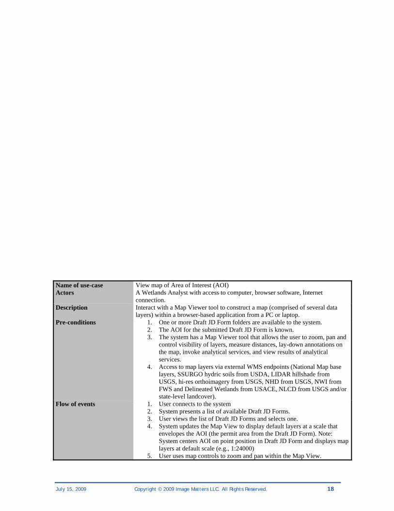
Name of use-case View map of Area of Interest (AOI) Actors A Wetlands Analyst with access to computer, browser software, Internet
connection. Description Interact with a Map Viewer tool to construct a map (comprised of several data
layers) within a browser-based application from a PC or laptop. Pre-conditions 1. One or more Draft JD Form folders are available to the system.
2. The AOI for the submitted Draft JD Form is known. 3. The system has a Map Viewer tool that allows the user to zoom, pan and
control visibility of layers, measure distances, lay-down annotations on the map, invoke analytical services, and view results of analytical services.
4. Access to map layers via external WMS endpoints (National Map base layers, SSURGO hydric soils from USDA, LIDAR hillshade from USGS, hi-res orthoimagery from USGS, NHD from USGS, NWI from FWS and Delineated Wetlands from USACE, NLCD from USGS and/or state-level landcover).
Flow of events 1. User connects to the system 2. System presents a list of available Draft JD Forms. 3. User views the list of Draft JD Forms and selects one. 4. System updates the Map View to display default layers at a scale that
envelopes the AOI (the permit area from the Draft JD Form). Note: System centers AOI on point position in Draft JD Form and displays map layers at default scale (e.g., 1:24000)
5. User uses map controls to zoom and pan within the Map View.

July 15, 2009 Copyright © 2009 Image Matters LLC. All Rights Reserved. 19
6. System updates the Map View. 7. User uses the measure tool to measure distances (feet, meters, miles
and/or kilometers). 8. System reports measured distance in user-specified units. 9. User invokes Analytical Services for determing JD.
Post-conditions System presents a Map View comprised of user-selected/created layers (NHD water, NWI wetland polygons, hydric soils, terrain, annotations, and highlights the analytical results.
b. Understand the data sources and service integration points Service Description
National Hydrography Dataset (NHD) – Web Feature Service (WFS)
Serves USGS stream line segments through OGC-compliant WFS; supports Filter Encoding spec
National Wetlands Inventory – WFS
Serves FWS wetland polygons through OGC-compliant WFS; supports Filter Encoding spec
Intersection GeoAnalysis – Web Processing Service
Find geometric intersection of features from two different sets of vector geometries accessed via WFS
Proximity GeoAnalysis – Web Processing Service
Finds distance between closest features from two different sets of vector geometries accessed via WFS
c. Catalog your Functional Requirements Wetlands JD Analyzer Requirements Functional
1. Application must connect to and query the NWI Web Feature Service (WFS) to identify wetland features
2. Application must display wetland query results on a map 3. Application must connect to and query the NHD Web Feature Service (WFS) to
identify stream features 4. Application must connect to and invoke a Web Processing Service (WPS) to perform
intersection-based and proximity-based analysis of wetlands and streams 5. Application must display analysis results in tabular form and on a map 6. Application should provide the user the ability to select wetlands and streams from
the map and display information about them 7. Application should allow the user to browse the wetland and stream features used in
the analysis within a report detailing the results of the analysis
July 15, 2009 Copyright © 2009 Image Matters LLC. All Rights Reserved. 20
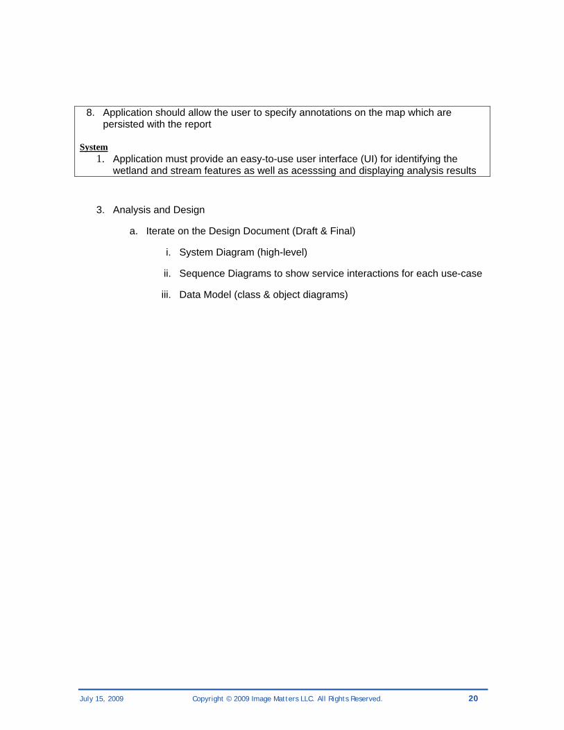
8. Application should allow the user to specify annotations on the map which are persisted with the report
System
1. Application must provide an easy-to-use user interface (UI) for identifying the wetland and stream features as well as acesssing and displaying analysis results
3. Analysis and Design
a. Iterate on the Design Document (Draft & Final)
i. System Diagram (high-level)
ii. Sequence Diagrams to show service interactions for each use-case
iii. Data Model (class & object diagrams)
July 15, 2009 Copyright © 2009 Image Matters LLC. All Rights Reserved. 21
4. Implementation
a. Understand the target runtime environment and integrations
b. Choose your development tools and frameworks early
c. Iterate on Integration Plan (Draft & Final)
5. Test
a. Iterate on the Test Plan (Initial, Final)
i. Start with the use-cases and requirements!
ii. Analyze results and go to Break-Fix-Test cycle sooner.
6. Deployment
a. Deployment model
b. Don’t forget the Installation and Maintenance Plan
July 15, 2009 Copyright © 2009 Image Matters LLC. All Rights Reserved. 22
6. Best Practices for Installation and Configuration 6.1. Lessons learned about Geospatial Data accessed via Open
Web Services • Working with different WFS services hosting the same data presents a challenge in
that each implementation almost invariably models the data differently and thus the data must be normalized against a common schema for processing by the “Wetlands JD Analyzer” (JDA) Web Processing Service (WPS). JDA achieves normalization through implementations of WFS clients that translate from the actual schema to the normalized schema during feature requests. Future versions could include generic clients that make use of configured mappings, allowing normalization without requiring new Java code.
• Different WFS services hosting the same data can also result in data quality issues such as varying resolutions (simplification of the data’s geometric representations
July 15, 2009 Copyright © 2009 Image Matters LLC. All Rights Reserved. 23
for performance or other reasons) and data coverage (incomplete data sets compared to other WFS services hosting a more comprehensive version of the same data). The section that follows provides more information about dealing with WFS differences.
• For performance reasons, certain WMS layers should be cached in a tiling scheme to prevent tiling map clients (such as OpenLayers which is used by the userSmarts™ RCP framework) from clogging the WMS with map requests for a series of tiles each time the user pans or zooms.
Authenticated data services present a challenge in that each step of the process that must make use of one of these services is required to have access to the authentication information or be able to acquire it. In the case of JDA, authenticated WFS requires several different components to have access to the credentials for the user, such as the WPS processor (intersection or proximity) and the WFS client used when compiling reports and generating HTML and CSV versions of reports.
6.2. Managing Differences among Web Feature Services As mentioned, different OGC WFS instances may present similar data in unique ways. JDA uses WFS to provide the input data – both NWI wetlands and NHD streams - for its WPS processing functionality. In addition, JDA also allows configuring different WFS instances from which to request NWI wetlands data. Since these WFS services may represent their data differently from each other and JDA expects a common data schema from which it may reliably extract portions of the data for calculation, extra steps must be taken when communicating with these services:
1. Service-level protocol variations must be taken into account, such as different versions of the WFS specification, support for optional service operations and parameters, and non-compliant WFS implementations.
2. Service instance variations such as data in different geographic projections, which may require requests to be projected into the coordinate reference system of the WFS as well as projecting WFS responses into a common projection used by the system
3. Data integrity, both in terms of having all necessary data components and having valid values within those components
4. Data coverage (spatial extent, or envelope)
5. Authentication and authorization

July 15, 2009 Copyright © 2009 Image Matters LLC. All Rights Reserved. 24
Case Study: Indus WFS versus OpenGeo/IU “Cloud” WFS
JDA is designed to deal with some of these issues:
1. There are no protocol variations among the different NWI WFS services used by JDA
2. The “OpenGeo/IU ‘Cloud’ WFS” hosts its NWI wetlands data in a “true” EPSG:4326 projection (latitude,longitude). The “Indus WFS” supports requests and responses in the more common longitude-first decimal degrees projection. To normalize the geometries between the two types of data (and the requests for the data), a coordinate swapping transform is applied when requesting data. JDA expects the longitude-first form, so the transform is only applied when communicating with the “Cloud” WFS
3. Both the “Cloud” and Indus WFS instances contain all necessary information for calculations by JDA, although this information is represented differently between the two, requiring further processing to normalize this information into a common representation before using it during WPS calculations
4. Only the Indus WFS provides the complete coverage of NWI wetlands data
5. Neither instance requires authentication or authorization to access its data
Supporting new Web Feature Services
To support a new WFS within the WPS of the JDA, several things must be done:
• Determine if the WFS requires authentication to access the data. If so, client classes which communicate with the WFS must be updated to support sending credentials when requesting data
• Determine the version of the WFS specification the service uses. If there are differences from the 1.1.0 version, client classes which communicate with the WFS must be updated accordingly to accommodate these differences if necessary
• Determine the projection of the data within the WFS. If the data is not longitude-first decimal degrees, then an appropriate transformation must be applied when accepting results from the WFS. In addition, if the WFS only accepts requests in the projection of its data, then the reverse transform must be applied when issuing the requests
• Determine the schema of the data within the WFS. Locate inconsistencies with the baseline common schema used by JDA. For the existing two WFS instances, separate client classes exist which communicate with the WFS using the userSmarts™ CX library for OGC services and transform the data into the common representation
July 15, 2009 Copyright © 2009 Image Matters LLC. All Rights Reserved. 25
7. Lessons Learned: Geospatial Services in the Cloud and in a SOA
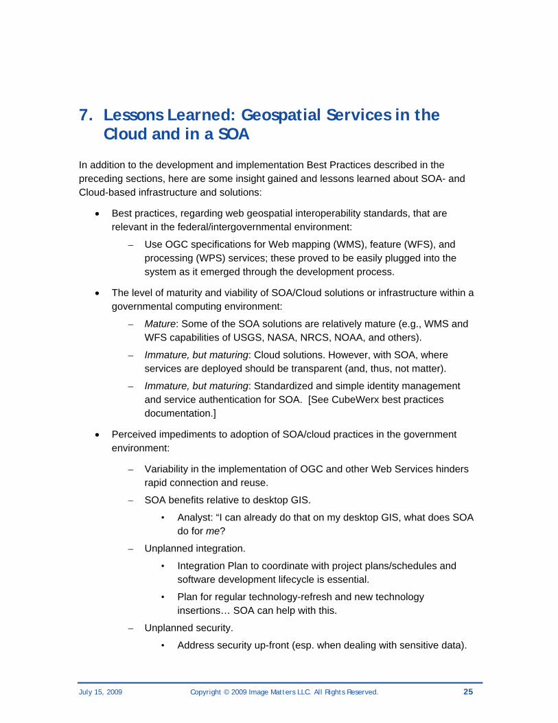
In addition to the development and implementation Best Practices described in the preceding sections, here are some insight gained and lessons learned about SOA- and Cloud-based infrastructure and solutions:
• Best practices, regarding web geospatial interoperability standards, that are relevant in the federal/intergovernmental environment:
– Use OGC specifications for Web mapping (WMS), feature (WFS), and processing (WPS) services; these proved to be easily plugged into the system as it emerged through the development process.
• The level of maturity and viability of SOA/Cloud solutions or infrastructure within a governmental computing environment:
– Mature: Some of the SOA solutions are relatively mature (e.g., WMS and WFS capabilities of USGS, NASA, NRCS, NOAA, and others).
– Immature, but maturing: Cloud solutions. However, with SOA, where services are deployed should be transparent (and, thus, not matter).
– Immature, but maturing: Standardized and simple identity management and service authentication for SOA. [See CubeWerx best practices documentation.]
• Perceived impediments to adoption of SOA/cloud practices in the government environment:
– Variability in the implementation of OGC and other Web Services hinders rapid connection and reuse.
– SOA benefits relative to desktop GIS.
• Analyst: “I can already do that on my desktop GIS, what does SOA do for me?
– Unplanned integration.
• Integration Plan to coordinate with project plans/schedules and software development lifecycle is essential.
• Plan for regular technology-refresh and new technology insertions… SOA can help with this.
– Unplanned security.
• Address security up-front (esp. when dealing with sensitive data).

July 15, 2009 Copyright © 2009 Image Matters LLC. All Rights Reserved. 26
• Win confidence of management first.
• Design and build for it from start.
– Organizational readiness.
• Make sure everybody’s on board.
• Observations on SOA benefits
– Each incremental capability or new service becomes part of an agency geospatial service portfolio
– Quicker time to benefit (ROI)
– Availability to all who need it – highly scalable
– Leave data with its steward
– As sophistication of new services increase, incremental costs do not
– Ease of use. Complexity stays under the hood – minimal training, easier maintenance.
• Observations on SOA Lessons
– Incrementally build and test new capabilities by prototyping
• Effective means to communicate and coordinate capabilities and requirements with stakeholders
• Rapid development (e.g., 1-2 week increments)
• Refining the user experience (uX) takes time!
– Rich Internet applications can be developed and delivered through the thinnest of clients (i.e., browser)
• Far more functionality is available than just web-mapping: geospatial analysis over the Web without expensive server or desktop software.
• The line between GIS and the GeoWeb is blurring with lots of choices
– Standards-based framework is essential
• Agency (and partner) voices are increasingly advocating standards
– Real money is required to host services
• It takes people, gear, licenses, Service Level Agreements (SLA), and reliable network communications to host services yourself; if feasible, consider a Cloud Computing solution for hosting non-sensitive data and services
July 15, 2009 Copyright © 2009 Image Matters LLC. All Rights Reserved. 27
Glossary of SOA Terminology
Atom Publishing Protocol
A REST-style protocol and service specification for using ATOM as an information service about collections of Atom and other feeds. See http://tools.ietf.org/html/rfc5023.
Atom Syndication Format
An XML-based message syndication format, commonly used to convey time-dependent news items to news readers. Atom is formally defined using XML Infoset and is an IETF proposed standard. See http://tools.ietf.org/html/rfc4287.
blog
A web log or diary. Blogs are syndicated using formats such as RSS or Atom in addition to their standard HTML formats. Many blog software and service providers have programming interfaces for blog writing that allow posting from a variety of client devices.
bounding box
1. portion of a coordinate space that lies between a lower bound and an upper bound in each dimension of a coordinate reference system
2. a set of 2, 4, 6 or 8 numbers indicating the upper and lower bounds of an interval (1D), rectangle (2D), parallelpiped (3D), or hypercube along each axis of a given CRS (http://www.opengeospatial.org/ogc/glossary)
capabilities XML
Service-level metadata [encoded in XML] describing the operations and content available at a service service metadata. (http://www.opengeospatial.org/ogc/glossary)
capability
A real-world effect that a service provider is able to provide to a service consumer. (http://docs.oasis-open.org/soa-rm/v1.0/soa-rm.pdf)
client
A software component that can invoke an operation performed by a server. (http://www.opengeospatial.org/ogc/glossary)
geographic information
information concerning phenomena implicitly or explicitly associated with a location relative to the Earth [ISO 19128 draft]
July 15, 2009 Copyright © 2009 Image Matters LLC. All Rights Reserved. 28
GEO Microformat
An XHTML extension that encodes latitude and longitude.
GeoRSS
An extension RSS and Atom that allows geospatial information (such as the geo-location) to be embedded in a syndication feed. GeoRSS is an Open Geospatial Consortium standard and is supported by tools such as Google Maps.
interaction
The activity involved in making using of a capability offered, usually across an ownership boundary, in order to achieve a particular desired real-world effect. (http://docs.oasis-open.org/soa-rm/v1.0/soa-rm.pdf)
interface
1. A named set of operations that characterize the behaviour of an entity.
2. An implementation of operations including the syntax of the interaction for a given distributed computing technology.
3. A shared boundary between two functional entities.
4. An established ordering of parameters (with specific names and data types) and instructions (with specific names and functions) that enables one software component to exchange data and instructions with another software component. (http://www.opengeospatial.org/ogc/glossary)
interoperability
capability to communicate, execute programs, or transfer data among various functional units in a manner that requires the user to have little or no knowledge of the unique characteristics of those units [ISO 2382-1]
literal
any process input or output whose value can be represented in a character string, supplemented by metadata as needed
literal (XML encoding)
any process input or output whose value can be represented in a xsd:string supplemented by XML attributes as needed NOTE A literal process input or output can be a character string, integer, general number, URI, measure, etc.

July 15, 2009 Copyright © 2009 Image Matters LLC. All Rights Reserved. 29
map
A two-dimensional visual portrayal of geospatial data. A map is not the data itself. (http://www.opengeospatial.org/ogc/glossary)
microformats
Conventional extensions of XHTML using <div> and <span> tags to semantically describe small piece of metadata. Microformat rendering as HTML can be governed with CSS, and microformats can be associated with JavaScript tools.
operation
1. A single step performed by a computer in the execution of a program, or, in the context of object-oriented programming. (http://www.opengeospatial.org/ogc/glossary)
2. Specification of an interaction that can be requested from an object to effect behavior. [ISO 19119]
output
result returned by a process
parameter
variable whose name and value are included in an operation request or response
process
model or calculation that is made available at a service instance
request
Invocation of an operation by a client. (http://www.opengeospatial.org/ogc/glossary)
response
Result of an operation returned from a server to a client. (http://www.opengeospatial.org/ogc/glossary)
REST
Representational State Transfer, an alternative formulation of Web services. In place of WSDL, REST systems use the HTTP verbs such as GET, POST, PUT, DELETE for all operations. Operations are performed on URLs, which typically respond with XML messages. XML message formats can be SOAP, RSS, Atom, etc. Other message formats

July 15, 2009 Copyright © 2009 Image Matters LLC. All Rights Reserved. 30
such as JSON can be used. See http://www.ics.uci.edu/~fielding/pubs/dissertation/top.htm.
RSS
A popular XML-based message syndication format, commonly used to convey time-dependent news items to news readers. RSS has several versions.
service instance
a particular instance of a service [ISO 19119 edited]
service
1. The means by which the needs of a consumer are brought together with the capabilities of a provider. (http://docs.oasis-open.org/soa-rm/v1.0/soa-rm.pdf)
2. distinct part of the functionality that is provided by an entity through interfaces [ISO 19119]
3. A computation performed by a software entity on one side of an interface in response to a request made by a software entity on the other side of the interface. [ISO 19119]
4. A collection of operations, accessible through an interface, that allows a user to evoke a behavior of value to the user. [ISO 19119]
5. capability which a service provider entity makes available to a service user entity at the interface between those entities [ISO 19104 terms repository]
service chain
A sequence of services where, for each adjacent pair of services, occurrence of the first action is necessary for the occurrence of the second action. [ISO 19119]
service consumer
An entity which seeks to satisfy a particular need through the use capabilities offered by means of a service. (http://docs.oasis-open.org/soa-rm/v1.0/soa-rm.pdf)
service description
The information needed in order to use, or consider using, a service. (http://docs.oasis-open.org/soa-rm/v1.0/soa-rm.pdf)
July 15, 2009 Copyright © 2009 Image Matters LLC. All Rights Reserved. 31
service interface
The means by which the underlying capabilities of a service are accessed. (http://docs.oasis-open.org/soa-rm/v1.0/soa-rm.pdf)
service metadata
metadata describing the operations and geographic information available at a server [ISO 19128 draft]
Service Oriented Architecture (SOA)
1. A computer systems architectural style for creating and using business processes, packaged as services, throughout their lifecycle. SOA also defines and provisions the IT infrastructure to allow different applications to exchange data and participate in business processes. These functions are loosely coupled with the operating systems and programming languages underlying the applications. SOA separates functions into distinct units (services), which can be distributed over a network and can be combined and reused to create business applications.These services communicate with each other by passing data from one service to another, or by coordinating an activity between two or more services. (http://en.wikipedia.org/wiki/Service-oriented_architecture)
2. A paradigm for organizing and utilizing distributed capabilities that may be under the control of different ownership domains. It provides a uniform means to offer, discover, interact with and use capabilities to produce desired effects consistent with measurable preconditions and expectations. (OASIS, http://www.oasis-open.org)
3. A system for linking resources on demand. In an SOA, resources are made available to other participants in the network as independent services (http://www.ianywhere.com/developer/rfid_anywhere/glossary.html)
4. Defines how two or more entities interact in such a way as to enable one entity to perform a unit of work on behalf of another entity. The unit of work is referred to as a service, and the service interactions are defined using a well-defined description language. (http://www.dunelm.com/resources/glossary.html)
5. A software design that integrates business functions. Users are able to decide the information which is to be shared between the functions. SOA is therefore more flexible and more loosely coupled than ERP and generally more suitable for service rather than manufacturing companies. (http://www.bpic.co.uk/jargon.htm)
6. A paradigm for design, development, deployment and management of a loosely coupled business application infrastructure. (http://keyintegrity.com/en/)
7. An architecture, the aim of which is to achieve a loose connection between integrated systems. From a common public Danish perspective, the integration of IT systems across public and private organisations is part of the vision of digital administration. (http://www.capevo.com/wm139851)

July 15, 2009 Copyright © 2009 Image Matters LLC. All Rights Reserved. 32
8. A service-oriented architecture is essentially a collection of services. These services communicate with one another. The communication can involve either simple data passing or it can involve two or more services coordinating some activity. (http://www.reactivity.com/soa/glossary.html)
9. expresses a business-driven approach to software architecture that supports integrating the business as a set of linked, repeatable business tasks, or "services". SOA is usually based on a set of Web services standards. (http://www.efforts-project.org)
service provider
An entity (person or organization) that offers the use of capabilities by means of a service. (http://docs.oasis-open.org/soa-rm/v1.0/soa-rm.pdf)
SOAP (Simple Object Access Protocol)
An XML network message format commonly used to convey instructions and responses between services in an SOA. SOAP messages are commonly transported using HTTP. See http://www.w3.org/TR/soap/.
version
version of an Implementation Specification (document) and XML Schemas to which the requested operation conforms. NOTE An OWS Implementation Specification version may specify XML Schemas against which an XML encoded operation request or response must conform and should be validated.
Web Service
1. A Web service is a software system designed to support interoperable machine-to-machine interaction over a network. It has an interface described in a machine-processable format (specifically WSDL). Other systems interact with the Web service in a manner prescribed by its description using SOAP messages, typically conveyed using HTTP with an XML serialization in conjunction with other Web-related standards. http://www.w3.org/TR/ws-arch/.
2. Specific method of implementing a service, using the Internet (XML, TCP/IP) as the transport mechanism and conforming to a specific set of standards (WSDL, SOAP, etc). Can be internally provided or can be offered externally. [PGFSOA, 2008]
Web Service Architecture (WSA)
A form of SOA for network-based machine-to-machine interaction that is based on World Wide Web Consortium standards such as HTTP, XML, SOAP, WSDL, etc. See http://www.w3.org/TR/ws-arch/.
July 15, 2009 Copyright © 2009 Image Matters LLC. All Rights Reserved. 33
workflow
automation of a business process, in whole or part, during which documents, information or tasks are passed from one participant to another for action, according to a set of procedural rules
WSDL (Web Services Description Language)
An XML language for describing network service programming interfaces. WSDL is typically used by a Web service to describe how to construct SOAP messages that it can consume and the format of its responses. See http://www.w3.org/TR/wsdl.
XML (Extensible Markup Language) 1. Extensible Markup Language is a non-proprietary subset of SGML (Standard
Generalized Markup Language). It is focused on data structure and uses tags to specify the content of the data elements in a document. [PGFSOA, 2008]
2. Describes a class of data objects called XML documents and partially describes the behavior of computer programs which process them. A data object is an XML document if it is well-formed… [W3C, http://www.w3.org/TR/2000/REC-xml-20001006)


![Service Oriented Architecture (SOA) [5/5] : SOA Best Practices](https://static.fdocuments.in/doc/165x107/547a35e7b379593a2b8b494c/service-oriented-architecture-soa-55-soa-best-practices.jpg)