Documentation Servo motors AM8000 and AM8500 - …€¦ · Documentation Servo motors AM8000 and...
57
Documentation Servo motors AM8000 and AM8500 Fan cooled 1.9 2017-09-18 Version: Date:
Transcript of Documentation Servo motors AM8000 and AM8500 - …€¦ · Documentation Servo motors AM8000 and...

Documentation
Servo motors AM8000 and AM8500
Fan cooled
1.92017-09-18
Version:Date:


Table of contents
Servo motors AM8000 and AM8500 3Version: 1.9
Table of contents1 Foreword .................................................................................................................................................... 5
1.1 Notes on the documentation........................................................................................................... 51.2 Documentation Issue Status........................................................................................................... 61.3 Appropriate use .............................................................................................................................. 7
2 Guidelines and Standards ........................................................................................................................ 82.1 EC declaration of conformity........................................................................................................... 9
3 For your safety......................................................................................................................................... 113.1 Staff qualification .......................................................................................................................... 113.2 Description of symbols.................................................................................................................. 123.3 Notes for the AM8000 and AM8500 (incl. Fan) ............................................................................ 13
4 Handling ................................................................................................................................................... 154.1 Transport ...................................................................................................................................... 154.2 Packaging ..................................................................................................................................... 154.3 Storage ......................................................................................................................................... 154.4 Maintenance / Cleaning ................................................................................................................ 164.5 Disposal ........................................................................................................................................ 16
5 Product identification.............................................................................................................................. 175.1 AM8000 and AM8500, scope of supply ........................................................................................ 175.2 AM8000 and AM8500 (fan) nameplate......................................................................................... 175.3 Type key AM8000 and AM8500 (fan) ........................................................................................... 18
6 Technical description.............................................................................................................................. 206.1 Design of the motors..................................................................................................................... 206.2 General technical data.................................................................................................................. 206.3 Power derating.............................................................................................................................. 216.4 Standard features ......................................................................................................................... 22
6.4.1 Style ................................................................................................................................. 226.4.2 Shaft end, A-side ............................................................................................................. 226.4.3 Flange .............................................................................................................................. 226.4.4 Protection class................................................................................................................ 236.4.5 Overtemperature protection ............................................................................................. 236.4.6 Insulation material class................................................................................................... 236.4.7 Vibration class.................................................................................................................. 236.4.8 Vibrations and shocks...................................................................................................... 236.4.9 Connection technology .................................................................................................... 236.4.10 Feedback System ............................................................................................................ 246.4.11 Holding brake................................................................................................................... 246.4.12 Pole number..................................................................................................................... 24
6.5 Options ......................................................................................................................................... 256.6 Selection criteria ........................................................................................................................... 256.7 Transport, assembly and disassembly ......................................................................................... 266.8 Installation fan body...................................................................................................................... 26
7 Mechanical installation ........................................................................................................................... 277.1 Important notes............................................................................................................................. 277.2 Flange mounts .............................................................................................................................. 28

Table of contents
Servo motors AM8000 and AM85004 Version: 1.9
8 Electrical installation............................................................................................................................... 298.1 Important notes............................................................................................................................. 298.2 Connection of motors with pre-assembled cables ........................................................................ 308.3 Connection of the fan with power admission ................................................................................ 318.4 AX5000 connection diagram for motors with OCT-Feedback ...................................................... 328.5 AX5000 connection diagram for motors with OCT-Feedback ...................................................... 338.6 AX5000 connection diagram for motors with OCT-Feedback ...................................................... 348.7 AX5000 connection diagram for motors with Resolver................................................................. 358.8 AX5000 connection diagram for motors with Resolver................................................................. 368.9 AX5000 connection diagram for motors with Resolver................................................................. 378.10 AX5000 connection diagram for motors with Resolver................................................................. 388.11 AX5000 connection diagram for mototrs with Hiperface............................................................... 39
9 Comissioning........................................................................................................................................... 409.1 Important notes............................................................................................................................. 409.2 Guide for commissioning of the motor .......................................................................................... 419.3 Guide for commissioning of the fan .............................................................................................. 419.4 Troubleshooting ............................................................................................................................ 42
10 Technical data.......................................................................................................................................... 4310.1 AM805x and AM855x ................................................................................................................... 44
10.1.1 Dimensional drawing AM805x and AM855x .................................................................... 4510.1.2 Dimensional drawing AM805x-9000 and AM855x-9000.................................................. 4610.1.3 Radial / axial forces at the shaft end................................................................................ 4710.1.4 Characteristic torque / speed curves ............................................................................... 47
10.2 AM806x and AM856x ................................................................................................................... 4810.2.1 Dimensional drawing AM8061 and AM8561.................................................................... 4910.2.2 Dimensional drawing AM806x and AM856x with K-N-L winding ..................................... 5010.2.3 Dimensional drawing AM806x and AM856x with R-Q-T winding..................................... 5110.2.4 Radial / axial forces at the shaft end................................................................................ 5210.2.5 Characteristic torque / speed curves ............................................................................... 52
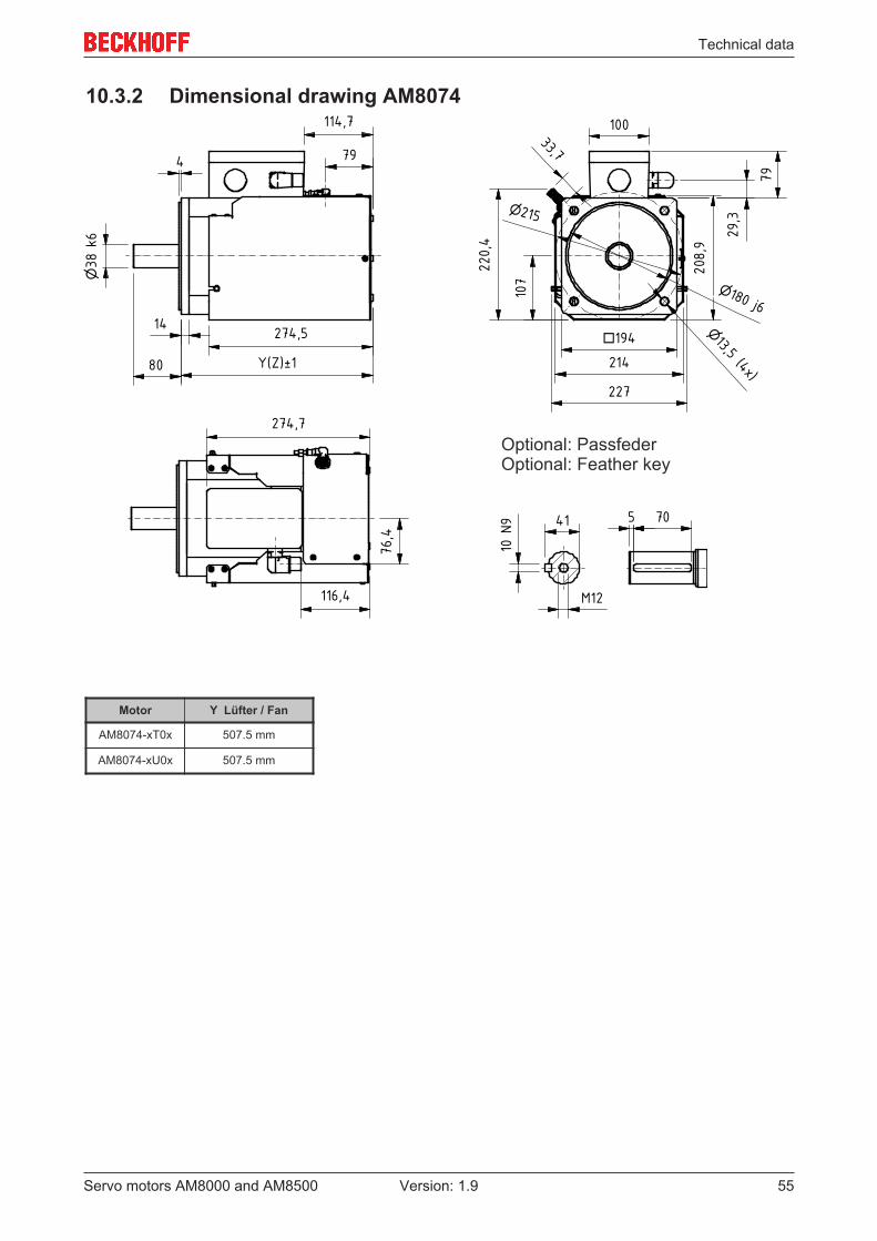
10.3 AM807x......................................................................................................................................... 5310.3.1 Dimensional drawing AM807x ......................................................................................... 5410.3.2 Dimensional drawing AM8074 ......................................................................................... 5510.3.3 Radial / axial forces at the shaft end................................................................................ 5610.3.4 Characteristic torque / speed curves ............................................................................... 56
11 Support and Service................................................................................................................................ 57

Foreword
Servo motors AM8000 and AM8500 5Version: 1.9
1 Foreword
1.1 Notes on the documentationThis description is only intended for the use of trained specialists in control and automation engineering whoare familiar with the applicable national standards.It is essential that the documentation and the following notes and explanations are followed when installingand commissioning the components. It is the duty of the technical personnel to use the documentation published at the respective time of eachinstallation and commissioning.
The responsible staff must ensure that the application or use of the products described satisfy all therequirements for safety, including all the relevant laws, regulations, guidelines and standards.
Disclaimer
The documentation has been prepared with care. The products described are, however, constantly underdevelopment.We reserve the right to revise and change the documentation at any time and without prior announcement.No claims for the modification of products that have already been supplied may be made on the basis of thedata, diagrams and descriptions in this documentation.
Trademarks
Beckhoff®, TwinCAT®, EtherCAT®, Safety over EtherCAT®, TwinSAFE®, XFC® and XTS® are registeredtrademarks of and licensed by Beckhoff Automation GmbH.Other designations used in this publication may be trademarks whose use by third parties for their ownpurposes could violate the rights of the owners.
Patent Pending
The EtherCAT Technology is covered, including but not limited to the following patent applications andpatents:EP1590927, EP1789857, DE102004044764, DE102007017835with corresponding applications or registrations in various other countries.
The TwinCAT Technology is covered, including but not limited to the following patent applications andpatents:EP0851348, US6167425 with corresponding applications or registrations in various other countries.
EtherCAT® is registered trademark and patented technology, licensed by Beckhoff Automation GmbH,Germany
Copyright
© Beckhoff Automation GmbH & Co. KG, Germany.The reproduction, distribution and utilization of this document as well as the communication of its contents toothers without express authorization are prohibited.Offenders will be held liable for the payment of damages. All rights reserved in the event of the grant of apatent, utility model or design.

Foreword
Servo motors AM8000 and AM85006 Version: 1.9
1.2 Documentation Issue StatusIssue Notice1.9 Chapter update:
Appropriate use 1.3; Guidelines and standards 2; For your safety 3; EC declaration ofconformity 2.1; Notes on the AM8000 and AM8500 (incl. Fan) 3.3; Disposal 4.5; Type key5.3; Installation fan body 6.8; Connection of the fan with power admission 8.3; Technicaldata 10.1 - 10.3New chapter:Dimensional drawing AM807x (OCT) 10.3.2; Dimensional drawing AM8074 10.3.3;Assignment planning of the Terminal box 10.3.3.1Deleted chapter:Documented motors
1.8 Chapter update:Foreword 1.0 and Safety 3.0; 6.7; 6.8; 8.3; 10.1; 10.1.1; 10.2; 10.2.1; 10.3; 10.3.1
1.7 Chapter update:Documented motors; 5.2; 5.3; 10.1
1.6 Chapter update:5.3; 6.4.10
1.5 Chapter update:10.1 – 10.3; 10.1.1 – 10.3.1
1.4 Chapter update:8.4; 8.5; 8.6; 8.7; 8.8; 8.9; 8.10; 8.11; 10.1; 10.2; 10.3
1.3 New chapter:8.3Chapter update:10.1; 10.2; 10.3
1.2 Chapter update:2.1; 5.3; 6.4.10; 7.1; 10.1; 10.3
1.1 Chapter update:10.1.1; 10.2.1; 10.3.1
1.0 First issue

Foreword
Servo motors AM8000 and AM8500 7Version: 1.9
1.3 Appropriate useBeckhoff servo motors of the AM8000 and AM8500 (incl. Fan) series are designed as drives for handlingequipment, textile machines, machine tools, packaging machines and similar machines with demandingrequirements in terms of dynamics. The motors of the AM8000 and AM8500 series are exclusively intendedfor speed- and/or torque-controlled operation via digital servo drives from Beckhoff Automation GmbH & Co.KG.
The thermal protection contact incorporated in the motor windings must be analysed and monitored.
Attention
Damage of the environment or equipmentThe servo motors are operated in the drive system in conjunction with Beckhoff servodrives. Please observe the entire documentation which consists of:
• AM8000 and AM8500 (incl. Fan) documentation → this manual• Complete documentation (online and paper) for Beckhoff servo drives available at
www.beckhoff.com.• Complete machine documentation (provided by the machine manufactor)
CAUTION
Caution – Risk of injury!Electronic equipment is not fail-safe. The machine manufacturer is responsible for ensuringthat the connected motors and the machine are brought into a safe state in the event of afault in the drive system.
Note
Special safety instructions for AM8000 and AM8500!The notes for the AM8000 and AM8500 (incl. Fan) [ 13] sections are also essential. Readcarefully!
The servomotors from the AM8000 and AM8500 (incl. Fan) series are exclusively designed for installation ascomponents in electrical systems or machines and may only be operated as integrated components of thesystem or machine.The motors may only be operated under the ambient conditions defined in this documentation.
Reasonably foreseeable misuse
Any use that deviates from the approved technical data (e.g. speed, force, temperature) is not use asintended and is therefore not permitted.
Improper use
The servo motors AM8000 and AM8500 (incl. Fan) are not suitable for use in the following areas:
• in ATEX zones without a suitable housing• in areas with aggressive environments (e.g. aggressive gases or chemicals)
The relevant standards and directives for EMC interface emissions must be complied with in residentialareas. The servo motors may only be installed in housings with appropriate shielding attenuation.
Guidelines and Standards
Servo motors AM8000 and AM85008 Version: 1.9
2 Guidelines and Standards
CAUTION
Danger for personsServomotors of the AM8000 and AM8500 series are not classified as products within themeaning of the EC Machinery Directive. Operation of the servomotors in machines or sys-tems is only permitted once the machine or system manufacturers has provided evidenceof EC conformity of the complete machine or system.

Guidelines and Standards
Servo motors AM8000 and AM8500 9Version: 1.9
2.1 EC declaration of conformity

Guidelines and Standards
Servo motors AM8000 and AM850010 Version: 1.9

For your safety
Servo motors AM8000 and AM8500 11Version: 1.9
3 For your safetyRead the section on safety and heed the notices to protect yourself against personal injury and materialdamages.
Liability limitations
All the components of the servo motors AM8000 and AM8500 (incl. Fan) are aupplied in certain hardwareand/or software configurations appropriate for the conditions of the application. Unauthorized modificationsto the hardware and/or software configurations other than those described in the documentation are notpermitted, and nullify the liability of Beckhoff Automation GmbH & Co. KG.
In addition, the following actions are excluded from the liability of Beckhoff Automation GmbH & Co. KG:
• Failure to comply with this documentation• Improper use• Untrained personnel• Use of unauthorized spare parts
3.1 Staff qualificationOnly technical personnel with knowledge of control and automation technology may carry out any of theillustrated work steps on the Beckhoff software and hardware, in particular on the servo motors AM8000 andAM8500 (incl. Fan).
The technical personnel must have knowledge of drive technology and electrical systems and must alsoknow how to work safely on electrical equipment and machines.
This also includes:• work preparation and• securing of the working environment (e.g. securing the control cabinet against being switched on
again).
The technical personnel must be familiar with the current and necessary standards and directives for theautomation and drive environment.

For your safety
Servo motors AM8000 and AM850012 Version: 1.9
3.2 Description of symbolsIn this documentation the following symbols are used with an accompanying safety instruction or note. Thesafety instructions must be read carefully and followed without fail!
Symbols that warn of personal injury:
DANGER
Serious risk of injury!This is an extremely dangerous situation. Disregarding the safety notice will lead to seriouspermanent injuries or even death.
WARNING
Risk of injury!This is a dangerous situation. Disregarding the safety notice may lead to serious injuries.
CAUTION
Personal injuries!This is a dangerous situation. Disregarding the safety notice may lead to minor injuries.
Symbols that warn of damage to property or equipment:
Attention
Warning of damage to property or the environment!This notice indicates disturbances in the operational procedure that could damage theproduct or the environment.
Symbols indicating further information or tips:
Note
Tip or pointer!This notice provides important information that will be of assistance in dealing with theproduct or software. There is no immediate danger to product, people or environment.
UL note!This symbol indicates important information regarding UL certification.

For your safety
Servo motors AM8000 and AM8500 13Version: 1.9
3.3 Notes for the AM8000 and AM8500 (incl. Fan)The notes are intended to avert danger and facilitate the handling of the servo motors AM8000 and AM8500(incl. Fan). They must be followed during installation, commissioning, production, troubleshooting,maintenance and trial or test assemblies.
The servo motor series AM8000 and AM8500 (incl. Fan) is not capable of running alone. They must alwaysbe installed in a machine or system. After installation the additional documentation and safety instructionsprovided by the machine manufacturer must be read and followed.
DANGER
Danger to life due to high voltage on the DC link capacitors of the servo driveAX8000!The DC link capacitors RB+ and RB- and the test contacts DC+ and DC- on the supply, axis and option modules can carry life-threatening voltages of ≥ 875 VDC.Take the following measures to avert danger:
• After disconnecting the servo drive from the mains supply, wait until the voltage hasfallen below 50 VDC. Only then is it safe to work.
• Measure the voltage on the test contacts properly.• Secure the work area properly and wear the PPE.
DANGER
Danger of life due to high voltage at the DC link capacitors of the servo driveAX5000!Due to the DC link capacitors dangerous voltage (> 875VDC) may persist at the DC link con-tacts “ZK+ and ZK- (DC+ and DC-)“ and “RB+ and RB-“ after the servo drive has been dis-connected from the mains supply.Take the following measures for Safety:
• Wait at:AX5101 – AX5125 and AX520x = 5 minutesAX5140/AX5160/AX5172 = 15 minutesAX5190/AX5191 = 30 minutes andAX5192/AX5193 = 45 minutesafter disconnected the servo drive from the mains supply. The device is safe once thevoltage has fallen below 50 V.
• Measure the voltage at the DC link contacts.• Secure the work area properly and wear the PPE.
WARNING
Serious burns due to hot surfaces on the devices!The surface temperature of the servo motors can reach ≥ 100 °C during operation of thesystem. There is an acute risk of sustaining burns to parts of the body and limbs.Take the following measures to avert danger:
• Do not touch any components (housing, etc.) shortly after or during operation.• Wait until all components have cooled sufficiently. At least 15 minutes.• Check the surface temperature with a thermometer.• DO NOT wear work gloves with a rubber coating. These can fuse with the skin on ac-
count of the high temperature and cause serious injuries.
Note
Notes on operation of the servo motors AM8000 and AM8500 (incl. Fan):Read this manual completely and carefully before using the servo motors. Notify the re-sponsible sales office immediately if any passages are not understandable. Refrain fromworking on the servo motor.

For your safety
Servo motors AM8000 and AM850014 Version: 1.9
Attention
Damage to the environment or devices• During installation it is essential to ensure that the specified ventilation clearances and
climatic conditions are adhered to. Further information can be found in the "Technicaldata" and "Mechanical installation" sections.
• If the servo drive is operated in contaminated ambient air, the cooling openings must bechecked regularly for blockage.

Handling
Servo motors AM8000 and AM8500 15Version: 1.9
4 Handling
4.1 Transport• Climate category: 2K3 according to EN 60721• Transport temperature: -25 °C - +70 °C, max. fluctuation 20 K/hour• Transport humidity: relative humidity 5% - 95%, non-condensing• The servomotor may only be transported by qualified personnel and in the manufaturer´s original
recyclable packaging.• Avoid hard impacts, particularly at the shaft end.• If the packaging is damaged, check the motor for visible damage. Inform the transport company and, if
necessary, the manufacturer.• Please check if the fan body was ordered included. Check the fan body for visible damage. Inform the
transport company and, if necessary, the manufacturer.
4.2 Packaging• Cardboard packaging (Packaging may consist of 2 cardboards!)
Motor type Max. stacking heightAM805x / AM855x 5AM806x / AM856x 2AM807x 1
4.3 Storage• Climate category: 2K3 according to EN 60721• Storage temperature: -25 °C - +70 °C, max. fluctuation 20 K/hour• Air humidity: relative humidity 5% - 95%, non-condensing• Max. stacking height: see table Packaging• Storage time: without limitation• Store only in the manufacturer’s original recyclable packaging.

Handling
Servo motors AM8000 and AM850016 Version: 1.9
4.4 Maintenance / Cleaning• Maintenance and cleaning only by qualified personnel.• The ball bearings have a grease filling with a service life of 30,000 hours under normal operating
conditions. The bearings should be replaced after 30,000 hours of operation under rated conditions.• Check the motor for bearing noise every 2,500 operating hours or once per year. If any noises are
heard, stop the operation of the motor. The bearings must be replaced.• In motors with optional shaft seal ring the ring must be lubricated every 5,000 hours. We recommend
„MobilgreaseTM FM 222“ from Mobil.• Opening the motor invalidates the warranty.• Clean the housing with isopropanol or similar.
Attention
Destruction of the servomotorNever immerse or spray the servomotor.
4.5 DisposalIn accordance with the WEEE 2012/19/EU Directives we take old devices and accessories back forprofessional disposal, provided the transport costs are taken over by the sender.
Send the devices with the note “For disposal” to:
Beckhoff Automation GmbH & Co. KGHuelshorstweg 20D-33415 Verl

Product identification
Servo motors AM8000 and AM8500 17Version: 1.9
5 Product identification
5.1 AM8000 and AM8500, scope of supplyPlease check that the delivery includes the following items:
• Motor from the AM 8000 or AM8500 series• Leaflet (short info)• Installation manual forced fan
5.2 AM8000 and AM8500 (fan) nameplate
Item number Explanation1 Servomotor type2 Protection class3 Thermo contact type4 Country of manufacture5 Serial number6 Brake type7 UL certification for USA / CAN8 Insulation class9 Rated output10 Nominal speed11 Rated voltage12 Standstill current13 Standstill torque

Product identification
Servo motors AM8000 and AM850018 Version: 1.9
5.3 Type key AM8000 and AM8500 (fan)
*) not for AM801x
Motor Flange size Connector plugAM805x F5 M23-speedtec® connector plugAM806x F6 M23-speedtec® connector plug (up to winding P), M40-speedtec connector plug (from winding Q)AM807x F7 M40-speedtec® connector plugAM855x F5 M23-speedtec® connector plugAM856x F6 M23-speedtec® connector plug (up to winding P), M40-speedtec connector plug (from winding Q)

Product identification
Servo motors AM8000 and AM8500 19Version: 1.9
This matrix should explain the motor flange sizes related to a gearbox mounting.
Motor sizes, named in the same line use the same adapter unit for a gearbox coupling.
Beckhoff Flange size AM3000 AM3100 AM3500 AM8000 AM8100 AM8500F1 AM301x AM311x - AM801x AM811x -F2 AM302x - - AM802x AM812x -Exception - AM312x - - - -F3 AM303x - - AM803x AM813x AM853xF4 AM304x - AM354x AM804x - AM854xF5 - - - AM805x - AM855xException AM305x - AM355x AM805x-xxxx-9 - -F6 AM306x - AM356x AM806x - AM856xF7 AM307x - - AM807x - -Exception AM308x - - - - -

Technical description
Servo motors AM8000 and AM850020 Version: 1.9
6 Technical description
6.1 Design of the motorsThe synchronous servomotors of the AM8000 and AM8500 series are brushless three-phase motors fordemanding servo-applications. In conjunction with our digital servo drives they are particularly suitable forpositioning tasks in industrial robots, machine tools, transfer lines etc. with demanding requirements in termsof dynamics and stability.
The servomotors are equipped with permanent magnets in the rotor. This advanced neodymium magneticmaterial makes a significant contribution to the motors´ exceptional dynamic properties. A three-phasewinding is housed in the stator, and this is powered by the servo drive. The motor has no brushes, thecommutation being implemented electronically in the servo drive.
The winding temperature is measured with a KTY 84.130 PTC (at 1st quarter 2018: PT 1000) silicon sensorand monitored in the servo drive.
The motors are available with or without built-in holding brake. The brake cannot be retrofitted.
The motors have a matt black powder coating (RAL 7016). The finish is not resistant against solvents (e.g.trichloroethylene, thinners or similar).
6.2 General technical dataAmbient conditions Admissible valueClimate category 3K3 according to EN 60721Ambient temperature (at rated values) +5 - +40°C for site altitudes up to 1000 m amsl.
It is vital to consult our applications department forambient temperatures above 40°C and encapsulatedinstallation of the motors.
Permissible humidity (at rated values) 95% relative humidity, non-condensingPower derating (currents and torques) For site altitudes above 1000 m amsl and 40°C
6 % at 2000m amsl17% at 3000m amslNo derating for site altitudes above 1000m amsl withtemperature reduction of 10K / 1000m
Ball bearing service life ≥ 30.000 operating hoursTechnical data see section 10Storage and transport data see section 4

Technical description
Servo motors AM8000 and AM8500 21Version: 1.9
6.3 Power deratingAmbient temperature
fT = Temperature utilisation factortA = Ambient temperature in °CCalculation of the power data when exceeding thespecified temperature limit > 40 °C up to 55 °C:M0_red = M0 x fT
Installation altitude
fH = Altitude utilisation factorh = Altitude in metresCalculation of the power data when exceeding thespecified installation altitude > 1000 m up to 3000 m:M0_red = M0 x fH
Ambient temperature and installation altitudeCalculation of the power data when exceeding the specified limits:Ambient temperature > 40°C and installation altitude > 1000 m.M0_red = M0 x fT x fH

Technical description
Servo motors AM8000 and AM850022 Version: 1.9
6.4 Standard features
6.4.1 StyleThe basic style for the AM8000 and AM8500 synchronous servomotors is IM B5 according to DIN EN60034-7.
The permitted mounting positions are specified in the technical data.
Attention
Motor damageTo avoid liquid entry damaging the motor, fluids (i.e. used for cleaning purposes) must beremoved from shaft when motor is mounted according to IM V3.
6.4.2 Shaft end, A-sideLoad transmission occurs force locked (zero-play) with a clutch on the cylindric end of the shaft A oroptionally by keyed connection with feather key groove according to DIN 6885. The lifecycle of the bearingsis 30.000 operating hours.
Radial force If the motor drive via pinions or toothed belts, then high radial forces will occur. The permissible values at theshaft end, depending on the speed, may be read from the diagrams in the Section 10. Please use the forcecalculation program “Beckhoff AM8000-Motors Radial forces, life cycle” available from our website for exactcalculation of the radial forces.
Axial force Axial forces arise when assembling pinions or pulleys on the shaft and using angular gearheads, forexample. Please use the force calculation program “Beckhoff AM8000-Motors Radial forces, life cycle”available from our website for exact calculation of the radial forces.
Coupling Double-coned collets, possibly in association with metal bellows couplings, have proven themselves asexcellent, zero backlash coupling elements.
6.4.3 FlangeFlange dimensions according to IEC standard, fit j6, accuracy according to DIN 42955
Tolerance class: N

Technical description
Servo motors AM8000 and AM8500 23Version: 1.9
6.4.4 Protection classStandard version – housing IP20Standard version – shaft feedthrough IP54Shaft feedthrough with shaft sealing ring IP65
6.4.5 Overtemperature protectionThe standard version of each motor is fitted with a KTY 84.130 (at 1st quarter 2018: PT 1000). Provided ourpreassembled motor cable is used, the KTY is integrated into the monitoring system of the digital servoamplifiers. Please configure the servo drive such that a motor temperature warning is issued at 100°C andthe motor is switched off at 140°C.
6.4.6 Insulation material classThe motors conform to insulation material class F according to IEC 60085 (UL 1446 class F).
6.4.7 Vibration classThe motors are made to vibration class A according to DIN EN 60034-14. For a speed range of 600-3600rpm and a shaft centre height between 54 - 97 mm, this means that the actual value of the permittedvibration severity is 1.6 mm/s.
Speed [rpm] Max. rel. vibration displacement[µm]
Max. run-out [µm]
<= 1800 90 23> 1800 65 16
6.4.8 Vibrations and shocksOCT and Multiturn:Vibration according to EN 60068-2-6 50 g / 10…2000 HzShocks according to EN 60068-2-27 100 g / 6 ms
6.4.9 Connection technologyThe motors are fitted with rotatable, angular connectors for the power supply and the feedback signals (onlyresolver + Hiperface).The mating connectors are not included in the scope of supply. We can supply preassembled feedback (onlyresolver + Hiperface) and power cables.The fans are provided with a M12 flange socket for grounding and power.
Technical description
Servo motors AM8000 and AM850024 Version: 1.9
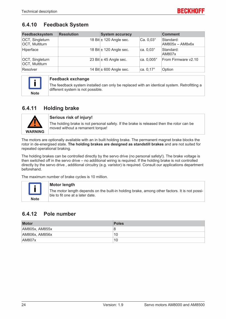
6.4.10 Feedback SystemFeedbacksystem Resolution System accuracy CommentOCT, SingleturnOCT, Multiturn
18 Bit ± 120 Angle sec. Ca. 0,03° Standard:AM805x – AM8x6x
Hiperface 18 Bit ± 120 Angle sec. ca. 0,03° Standard:AM807x
OCT, SingleturnOCT, Multiturn
23 Bit ± 45 Angle sec. ca. 0,005° From Firmware v2.10
Resolver 14 Bit ± 600 Angle sec. ca. 0,17° Option
Note
Feedback exchangeThe feedback system installed can only be replaced with an identical system. Retrofitting adifferent system is not possible.
6.4.11 Holding brake
WARNING
Serious risk of injury!The holding brake is not personal safety. If the brake is released then the rotor can bemoved without a remanent torque!
The motors are optionally available with an in built holding brake. The permanent magnet brake blocks therotor in de-energised state. The holding brakes are designed as standstill brakes and are not suited forrepeated operational braking.
The holding brakes can be controlled directly by the servo drive (no personal safety!). The brake voltage isthen switched off in the servo drive – no additional wiring is required. If the holding brake is not controlleddirectly by the servo drive , additional circuitry (e.g. varistor) is required. Consult our applications departmentbeforehand.
The maximum number of brake cycles is 10 million.
Note
Motor lengthThe motor length depends on the built-in holding brake, among other factors. It is not possi-ble to fit one at a later date.
6.4.12 Pole numberMotor PolesAM805x, AM855x 8AM806x, AM856x 10AM807x 10

Technical description
Servo motors AM8000 and AM8500 25Version: 1.9
6.5 OptionsHolding brake The holding brake is integrated in the motor. It increases the motor length and the rotor moment of inertia.
Radial shaft-sealing ringRadial shaft-sealing ring (FKM) for sealing against splash water. This increases the protection class of theshaft busching to IP65.
Father keyThe motors are available with feather key groove and fitted feather key according to DIN 6885. The rotor isbalanced with half a feather key.
Resolver
This model features a different feedback system in place oft he OCT or the hiperface.
Note
Installation options and reduction of rated values• With the exception of the sealing ring, the options cannot be retrofitted.• The option sealing ring can lead to a reduction oft he rated data.
6.6 Selection criteriaThe three-phase servomotors are designed for operation with the servo drive. Both together form a speed ortorque control loop.
The main selection criteria are:
• Standstill torque M0 [Nm]• Maximal torque Mmax [Nm]• Rated speed at rated supply voltage nn [min-1]• Moment of inertia of motor and load J [kgcm²]• Effective torque (calculated) Mrms [Nm]
The static load and the dynamic load (acceleration/braking) must be taken into account in the calculation ofthe required motors and the servo drive. Formulas and calculation example are available from ourapplications department on request.

Technical description
Servo motors AM8000 and AM850026 Version: 1.9
6.7 Transport, assembly and disassembly
CAUTION
Personal injuries!Protective clothing, protective gloves and safety boots must be worn at all times duringtransport, assembly and disassembly. Do not step under suspended motors.
The motors of the AM8x6x series can be moved with loopbelts.The motors of the AM8x1x to AM8x5x series can bemoved without auxiliary equipment.
The motors of the AM807x series are equipped with eyebolts as standard. These eyebolts are suitable forcrane hooks. For mount the fan body, the eye bolts should be removed, after the motor is installed on theunit rack.
6.8 Installation fan body
In the first step, mount the motor to the machine. For further information,see Chapter 7: "Mechanical Installation [ 27]".
Remove the eyebolts on the motor housing (only AM807x). The eyeboltsmust be loosened in the right direction of rotation as shown in the left pic-ture and pulled upwards.
Slide the fan body to the mechanical stop on the motor housing. Fastenthe fan cover with the four-head cap screw (4) and the cap nut on theside.
Use an Allen key SW 2.5 for tightening the cap screws (4 pieces). Thetightening torque is 3 Nm. For the cap nut on the side, use a SW 7wrench. The tightening torque is 2.5 Nm.
Make sure that there are no dirt particles in the tapped holes which pre-vent correct fastening of the screws.
Now connect the M12 connector for the fan and check the plug for a tightfit.
You will find further information in chapter 8.3: "Connection of the fanwith power admission [ 31]".
You have successfully installed your fan body.

Mechanical installation
Servo motors AM8000 and AM8500 27Version: 1.9
7 Mechanical installation
7.1 Important notes
Attention
Motor damage• Take care, especially during transport and handling that components are not bent and
that insulation clearances are not altered.• The site must be free of conductive and aggressive material. For V3-mounting (shaft
end upwards), make sure that no liquids can enter the bearings. If an encapsulated as-sembly is required, please consult our applications department beforehand.
• Ensure unhindered ventilation of the motors and observe the permissible ambient andflange temperatures. For ambient temperatures above 40 °C please consult our appli-cations department beforehand.
• Servomotors are precision devices.The flange and shaft are especially vulnerable dur-ing storage and assembly.It is important to use the locking thread which is provided totighten up couplings, gear wheels or pulleys and warm up the drive components, wherepossible.Blows or the use of force will lead to damage to the ball bearings, shaft, hold-ing brake and feedback System.
• Wherever possible, use only backlash-free, frictionally-locking collets or couplings. En-sure correct alignment of the couplings. A displacement will cause unacceptable vibra-tion and the destruction of the ball bearings and the coupling.
• For toothed belts, it is vital to observe the permissible radial forces. An excessive radialload on the shaft will significantly shorten the life of the Motor.
• Avoid axial loads on the motor shaft, as far as possible. Axial loading significantly short-ens the life of the Motor. Furthermore, it must be ensured that when using a collet, themotor shaft is degreased.
• In any case, avoid creating a mechanically constrained motor shaft mounting by using arigid coupling with additional external bearings (e.g. in a gearbox).
• Take note of the no. of motor poles and the no. of resolver poles and ensure that thecorrect setting is made in the used servo terminals. An incorrect setting can lead to thedestruction of the motor, especially with small Motors.
• Check compliance the permitted radial and axial loads FR and FA.When using a toothedbelt drive, the minimum permitted diameter of the pinion follows from the equation:
Mechanical installation
Servo motors AM8000 and AM850028 Version: 1.9
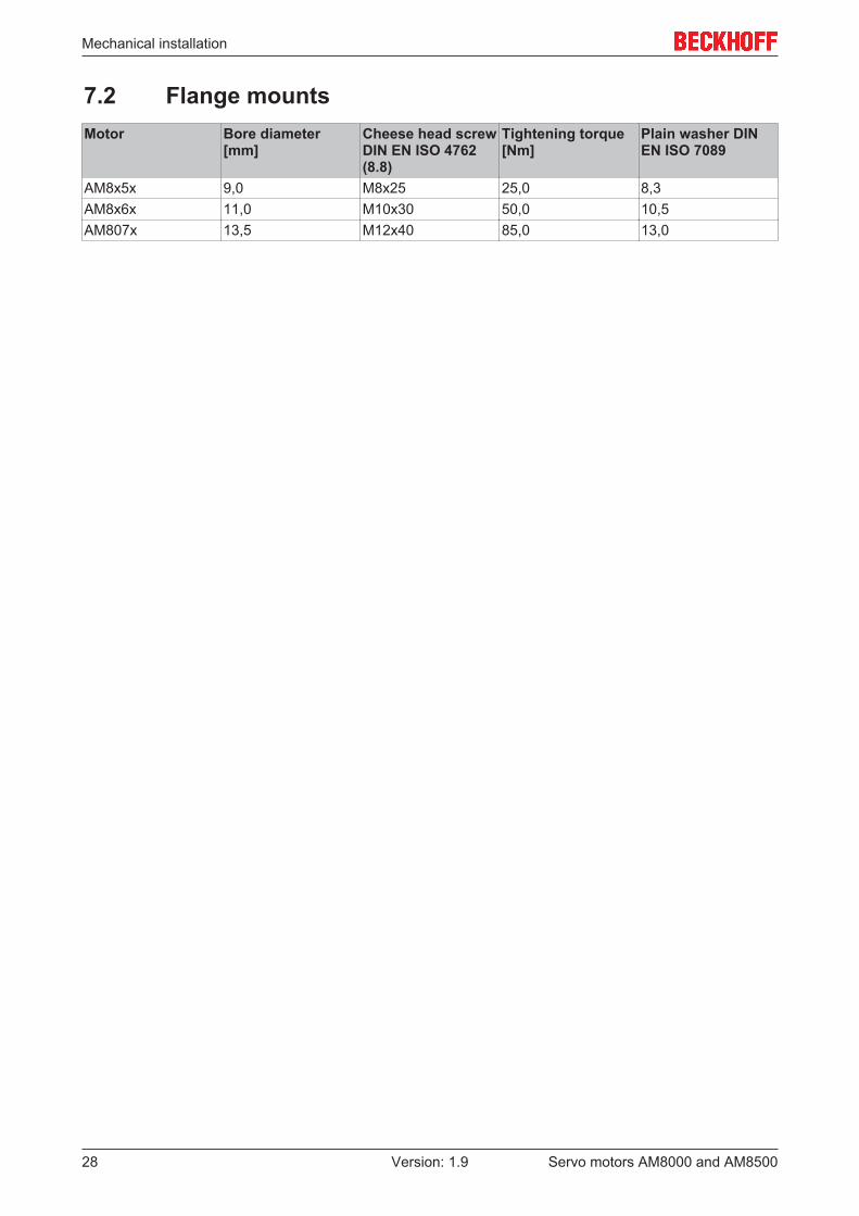
7.2 Flange mountsMotor Bore diameter
[mm]Cheese head screwDIN EN ISO 4762(8.8)
Tightening torque[Nm]
Plain washer DINEN ISO 7089
AM8x5x 9,0 M8x25 25,0 8,3AM8x6x 11,0 M10x30 50,0 10,5AM807x 13,5 M12x40 85,0 13,0
Electrical installation
Servo motors AM8000 and AM8500 29Version: 1.9
8 Electrical installation
8.1 Important notes
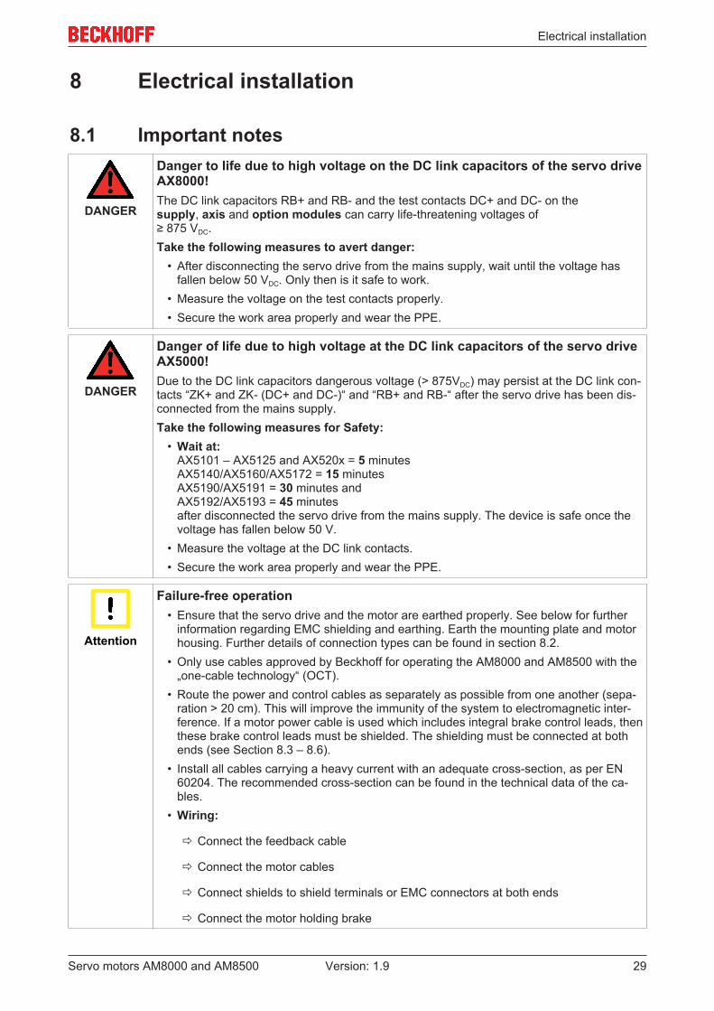
DANGER
Danger to life due to high voltage on the DC link capacitors of the servo driveAX8000!The DC link capacitors RB+ and RB- and the test contacts DC+ and DC- on the supply, axis and option modules can carry life-threatening voltages of ≥ 875 VDC.Take the following measures to avert danger:
• After disconnecting the servo drive from the mains supply, wait until the voltage hasfallen below 50 VDC. Only then is it safe to work.
• Measure the voltage on the test contacts properly.• Secure the work area properly and wear the PPE.
DANGER
Danger of life due to high voltage at the DC link capacitors of the servo driveAX5000!Due to the DC link capacitors dangerous voltage (> 875VDC) may persist at the DC link con-tacts “ZK+ and ZK- (DC+ and DC-)“ and “RB+ and RB-“ after the servo drive has been dis-connected from the mains supply.Take the following measures for Safety:
• Wait at:AX5101 – AX5125 and AX520x = 5 minutesAX5140/AX5160/AX5172 = 15 minutesAX5190/AX5191 = 30 minutes andAX5192/AX5193 = 45 minutesafter disconnected the servo drive from the mains supply. The device is safe once thevoltage has fallen below 50 V.
• Measure the voltage at the DC link contacts.• Secure the work area properly and wear the PPE.
Attention
Failure-free operation• Ensure that the servo drive and the motor are earthed properly. See below for further
information regarding EMC shielding and earthing. Earth the mounting plate and motorhousing. Further details of connection types can be found in section 8.2.
• Only use cables approved by Beckhoff for operating the AM8000 and AM8500 with the„one-cable technology“ (OCT).
• Route the power and control cables as separately as possible from one another (sepa-ration > 20 cm). This will improve the immunity of the system to electromagnetic inter-ference. If a motor power cable is used which includes integral brake control leads, thenthese brake control leads must be shielded. The shielding must be connected at bothends (see Section 8.3 – 8.6).
• Install all cables carrying a heavy current with an adequate cross-section, as per EN60204. The recommended cross-section can be found in the technical data of the ca-bles.
• Wiring:
ð Connect the feedback cable
ð Connect the motor cables
ð Connect shields to shield terminals or EMC connectors at both ends
ð Connect the motor holding brake

Electrical installation
Servo motors AM8000 and AM850030 Version: 1.9
Attention
HF interferenceThe ground symbol, which you will find in the wiring diagrams, indicates that you must pro-vide an electrical connection, with as large a surface area as possible, between the unit in-dicated and the mounting plate in the control cabinet. This connection is to suppress HF in-terference and must not be confused with the PE (protective earth) symbol (protective mea-sure according to EN 60204). Follow the instructions in the circuit diagrams in Sections 8.3to 8.6.
Note
Motor cable length at servo drives up to 25 AMotors with max. 400 V rated voltage:If the length of the motor cable is ≥ 25 m, then a motor choke is required for each motor.Motors with max. 480 V rated voltage:If the length of the motor cable is > 20 m, then a motor choke is required for each motor.The control cabinet should then have adequate space for motor chokes. In exceptionalcases (sensitive sensors etc.) it can be necessary to use a motor choke even for motor ca-ble lengths < 25 / 20 m. The motor choke is supplied with a connection cable. Do not alterthe configuration (cable length, cross-section etc.).
8.2 Connection of motors with pre-assembled cablesBeckhoff offers preassembled motor and feedback cables for safe, faster, and flawless installation of themotors. Beckhoff cables have been tested with regard to the materials, shielding and connectors used. Theyensure proper functioning and compliance with statutory regulations such as EMC, UL, etc. The use of othercables may lead to unexpected interference and invalidate the warranty.
• Carry out the wiring in accordance with the valid standards and regulations.• Only use our preassembled shielded cables for the power and feedback connections.• Connect up the shielding according to the wiring diagrams in sections 8.3 to 8.12. Incorrectly installed
shielding inevitably leads to EMC interference.
Detailed specifications of the cables are listed on our homepageDownload → Documentation → Drive Technology → Cable.

Electrical installation
Servo motors AM8000 and AM8500 31Version: 1.9
8.3 Connection of the fan with power admission
Connect the prefabricated control cableZK4054-6400-0xxx at the fan.To do this, proceed as follows:
• Connect the M12 connector for the fan. TheM12 connecter is at the control cable.
• Check the connector for a tight fit.For further information, please see chapter 6.8:"Installation fan body [ 26]".You have successfully connected your fan body.
Data of the power admission from the external fan
Data Symbol [Unit] AM8x5x AM8x6x AM8x7xSupply voltage ULA [VDC] 24Electrical power PLA [W] 4.6 9.8 31.2Current I [A] 0.19 0.41 1.3
Assignment planning of the connector plug
View of the sockets Contact at the connector plug Cable assignment1 PE (green / yellow)2 + 24 VDC (brown)3 not connected4 GND (blue)5 not connected
Note
Further information about the control cable ZK4054-6400-0xxx:The data sheet of the control cable can be found at:
www.beckhoff.com → Download → Data sheets → Cable and lines

Electrical installation
Servo motors AM8000 and AM850032 Version: 1.9
8.4 AX5000 connection diagram for motors with OCT-Feedback
Servo drives: AX5101 – AX5125 and AX52xxMotors: AM804x – AM806x and AM854x – AM856x (until P winding)
Electrical installation
Servo motors AM8000 and AM8500 33Version: 1.9
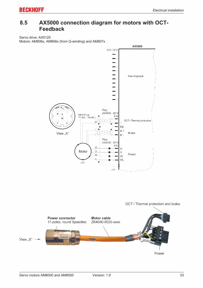
8.5 AX5000 connection diagram for motors with OCT-Feedback
Servo drive: AX5125Motors: AM806x, AM856x (from Q-winding) and AM807x

Electrical installation
Servo motors AM8000 and AM850034 Version: 1.9
8.6 AX5000 connection diagram for motors with OCT-Feedback
Servo drive: AX5140Motors: AM806x, AM856x (from Q-winding) and AM807x

Electrical installation
Servo motors AM8000 and AM8500 35Version: 1.9
8.7 AX5000 connection diagram for motors with ResolverServo drives: AX5101 – AX5125 and AX52xxMotors: AM804x – AM806x and AM854x – AM856x (until P-winding)
Electrical installation
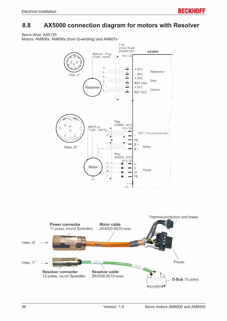
Servo motors AM8000 and AM850036 Version: 1.9
8.8 AX5000 connection diagram for motors with ResolverServo drive: AX5125Motors: AM806x, AM856x (from Q-winding) and AM807x

Electrical installation
Servo motors AM8000 and AM8500 37Version: 1.9
8.9 AX5000 connection diagram for motors with ResolverServo drive: AX5140Motors: AM806x, AM856x (from Q-Winding) and AM807x

Electrical installation
Servo motors AM8000 and AM850038 Version: 1.9
8.10 AX5000 connection diagram for motors with ResolverServo drives: AX5160 and AX5172Motors: AM806x, AM856x (from Q-winding) and AM807x

Electrical installation
Servo motors AM8000 and AM8500 39Version: 1.9
8.11 AX5000 connection diagram for mototrs with HiperfaceServo drives: AX5160 and AX5172Motors: AM806x, AM856x (from Q-winding) and AM807x

Comissioning
Servo motors AM8000 and AM850040 Version: 1.9
9 Comissioning
9.1 Important notes
DANGER
Danger to life due to high voltage on the DC link capacitors of the servo driveAX8000!The DC link capacitors RB+ and RB- and the test contacts DC+ and DC- on the supply, axis and option modules can carry life-threatening voltages of ≥ 875 VDC.Take the following measures to avert danger:
• After disconnecting the servo drive from the mains supply, wait until the voltage hasfallen below 50 VDC. Only then is it safe to work.
• Measure the voltage on the test contacts properly.• Secure the work area properly and wear the PPE.
DANGER
Danger of life due to high voltage at the DC link capacitors of the servo driveAX5000!Due to the DC link capacitors dangerous voltage (> 875VDC) may persist at the DC link con-tacts “ZK+ and ZK- (DC+ and DC-)“ and “RB+ and RB-“ after the servo drive has been dis-connected from the mains supply.Take the following measures for Safety:
• Wait at:AX5101 – AX5125 and AX520x = 5 minutesAX5140/AX5160/AX5172 = 15 minutesAX5190/AX5191 = 30 minutes andAX5192/AX5193 = 45 minutesafter disconnected the servo drive from the mains supply. The device is safe once thevoltage has fallen below 50 V.
• Measure the voltage at the DC link contacts.• Secure the work area properly and wear the PPE.
Comissioning
Servo motors AM8000 and AM8500 41Version: 1.9
9.2 Guide for commissioning of the motorThe procedure for commissioning is described as an example.
A different method may be appropriate or necessary, depending on the application of the Equipment.
• Check the assembly and orientation of the Motor.• Check the drive components (coupling, gear unit, pulley) for the correct seating and setting (observe
the permissible radial and axial forces).• Check the wiring and connections to the motor and the servo terminal. Check that the earthing is
correct.• Test the function of the holding brake, if used. (apply 24 VDC, the brake must be released).• Check whether the rotor of the motor revolves freely (release the brake, if necessary). Listen out for
grinding noises.• Check that all the required measures against accidental contact with live and moving parts have been
carried out.• Carry out any further tests which are specifically required for your System.• Now commission the drive according to the commissioning instructions for the servo terminal.• In multi-axis systems, individually commission each drive unit (servo terminal/motor(s)).
9.3 Guide for commissioning of the fanThe procedure for commissioning is describe as an example.
A different method may be appropriate or necessary, depending on the application of the Equipment.
• Check the assembly and orientation of the fan body.• Check the fan body for the correct seating and setting. See that the tightening torque of the screw is
correct.• Check the wiring and connection on the strip terminal. Check that the grounding is correct.• Check whether the fan revolves freely. Listen out for grinding noises.• Check that the grounding of the fan body is correct.• Check the direction of rotation of the fan. The air flow must blow over the motor.• Now take the fan in operation.

Comissioning
Servo motors AM8000 and AM850042 Version: 1.9
9.4 TroubleshootingThe following table is to be seen as a “First Aid” box. There can be a large number of different reasons for afault, depending on the particular conditions in your system. The fault causes described below are mostlythose which, directly influence the motor. Peculiarities which show up in the control behaviour can usually betraced back to an error in the parameterization of the servo drive. The documentation for the servo drive andthe commissioning software provides information of these matters.
For multi-axis systems there may be further hidden reasons for faults.
Our application department can give you further help with your problems.
Fault Possible cause Measures to remove the causeof the fault
Motor doesn´t rotate Servo drive not enabledBreak in setpoint leadMotor phases in wrong sequenceBrake not releasedDrive is mechanically blocked
Supply ENABLE signalCheck setpoint leadCorrect the phase sequence
Check brake controlCheck mechanism
Motor runs away Motor phases in wrong sequence Correct the phase sequenceMotor oscillates Break in the shielding of the
feedback cableAmplification to high
Replace feedback cable
Use motor default valuesError message: brake Short-circuit in the supply voltage
lead to the motor holding brakeFaulty motor holding brake
Remove the short circuit
Replace motorError message: output stage fault Motor cable has short circuit or
earth leakageMotor has short circuit or earthleakage
Replace motor cable
Replace motor
Error-message: feedback Connector is not properly pluggedin Break in cable, cable crushed orsimilar
Check connector
Check cables
Error-message: motor temperature Motor thermostat has switchedLoose connector or break in cable
Wait until the motor has cooleddown. Then investigate why themotor becomes so hot.Check connector, replace cable ifnecessary
Brake does not grip Required holding torque too highBrake faulty
Check the dimensioningReplace motor

Technical data
Servo motors AM8000 and AM8500 43Version: 1.9
10 Technical dataAll data, excluding the voltage constant, valid for 40 °C ambient temperature and 100 K overtemperature ofthe winding. The data can have a tolerance of +/- 10%.If a gear unit is attached the power may be reduced by up to 20%. This loss in performance has thermalreasons, since a gear unit that is subject to warming is installed at the motor flange intended for heatdissipation.
Term definitions
Standstill torque M0 [Nm]The standstill torque can be maintained indefinitely at a speed n < 100 rpm and rated ambient conditions.
Rated torque Mn [Nm]The rated torque is produced when the motor is drawing the rated current at the rated speed. The ratedtorque can be produced indefinitely at the rated speed in continuous operation (S1).
Standstill current I0rms [A]The standstill current ist he effective sinusoidal current which the motor draws at n < 100 rpm to produce thestandstill torque.
Peak current (pulse current) I0max [A]The peak current (effective sinusoidal value) is approximately equivalent to 5-times the rated standstillcurrent (3-times at AM806x, AM807x and AM856x). The configured peak current of the servo drive usedmust be smaller.
Torque constant KTrms [Nm/A]The torque constant defines how much torque in Nm is produced by the motor with standstill current. Therelationship is M0=I0 x KT.
Voltage constant KErms [mVmin]The voltage constant defines the induced motor EMF, as an effective sinusoidal value between twoterminals, at 20 °C per 1000 rpm.
Rotor moment of inertia J [kgcm²]The constant J is a measure of the acceleration capability of the motor. For instance, at l0 the accelerationtime tb from 0 to 3000 rpm is given as:
with M0 in Nm and J in kgcm2
Thermal time constant tTH [min]The constant tTH defines the time for the cold motor, under a load of l0 to heat up to an overtemperature of0,63 x 100 Kelvin.This temperature rise happens in a much shorter time when the motor is loaded with the peak current.
Release delay time tBRH [ms] / Application delay time tBRL [ms] of the brakeThese constants define the response times of the holding brake when operated with the rated voltage fromthe servo drive.
Winding inductance L [mH]The winding inductance is an specification of the motor inductance. This is get as an average value on twoenergized phases at 1 KHz. The saturation of the motor must be taken into account.

Technical data
Servo motors AM8000 and AM850044 Version: 1.9
10.1 AM805x and AM855xTechnical data Symbol
[Unit]AM80xx / AM85xx
51F 51J 51L 52G 52K 52N 53J 53L 53PElectrical data
Standstill torque* M0 [Nm] 6,20 6,30 6,30 10,70 10,70 9,60 15,40 15,40 13,30Standstill current Iorms [A] 3,50 5,80 11,10 4,30 8,50 13,60 6,40 11,90 18,60Max. mechanical speed Nmax [min-1] 9000Max. rated mains voltage UN [VAC] 480
UN =115V
Rated speed Nn [min-1] 500 1100 2300 400 900 1900 400 1000 1900Rated torque* Mn [Nm] 6,10 6,20 5,90 10,50 10,30 9,50 15,30 15,10 12,30Rated output Pn [kW] 0,32 0,71 1,42 0,44 0,97 1,90 0,65 1,58 2,45
UN =230V
Rated speed Nn [min-1] 1400 2600 4900 1000 2100 4000 1000 2200 4000Rated torque* Mn [Nm] 6,00 5,80 5,30 10,30 9,60 8,10 15,10 14,80 8,40Rated output Pn [kW] 0,88 1,58 2,72 1,08 2,11 3,40 1,58 3,40 3,52
UN =400V
Rated speed Nn [min-1] 2500 4750 8000 2000 4000 6000 2000 4000 5000Rated torque* Mn [Nm] 5,80 5,70 3,60 9,70 9,10 9,10 14,90 12,90 7,10Rated output Pn [kW] 1,52 2,74 3,02 2,03 3,77 4,08 3,12 5,41 3,72
UN =480V
Rated speed Nn [min-1] 3000 5000 8000 2300 4500 7000 2300 4500 7000Rated torque* Mn [Nm] 5,70 5,40 3,60 9,20 8,80 4,50 14,70 12,10 4,10Rated output Pn [kW] 1,79 3,22 3,01 2,21 4,14 4,24 3,54 5,84 3,00Peak current I0max [A] 12,10 20,90 37,70 17,90 33,60 60,70 26,90 50,90 89,70Peak torque M0max [Nm] 17,74 17,76 17,78 35,32 35,34 35,34 53,13 53,13 53,14Torque constant KTrms [Nm/A] 1,77 1,09 0,57 2,48 1,30 0,72 2,42 1,29 0,73Voltage constant KErms [mVmin] 125,0 73,00 40,00 167,0 89,00 49,00 168,0 89,00 51,00Winding resistance
Ph-Ph
R20 [Ω] 11,40 3,60 1,14 8,50 2,30 0,70 5,10 1,40 0,45
Winding resistance
Ph-Ph**
L [mH] 42,7 14,4 4,6 36,9 10,5 3,2 23,7 6,6 2,1
Connector plug M23-speedtec®
*reference flange aluminium 305 mm x 305 mm x 12,7 mm. **measured at 1kHz.The installation of a shaft seal ring leads to a reduction of the rated values.
Mechanical data AM8051 AM8551 AM8052 AM8552 AM8053 AM8553Rotor moment of inertia (without brake) J [kgcm2] 2,24 8,75 4,080 10,600 5,920 12,500Rotor moment of inertia (with brake) J [kgcm2] 2,90 9,41 4,74 11,20 7,04 ---Pole number 8 8 8 8 8 8Static friction torque MR [Nm] 0,021 0,021 0,036 0,036 0,050 0,050Thermal time constant tTH [min] 31 31 38 38 40 40Weight (without brake) G [kg] 5,20 6,60 6,80 8,10 8,50 9,90Weight (with brake) G [kg] 6,00 7,40 7,70 9,00 9,50 ---Permitted radial force at shaft end FR [N] see 10.5.2Permitted axial force FA [N]
Data of the power admission from the external fan
See chapter 8.3 “Connection of the fan with power admission”
Data for optional brake
Data Symbol [Unit] AM8051 / AM8052AM8551 / AM8552
AM8053AM8553
Holding torque at 120°C MBR [Nm] 9 13Supply voltage UBR [VDC] 24 +6 -10% 24 +6 -10%Electrical power PBR [W] 18 17Current Ion [A] 0,54 0,51Release delay time tBRH [ms] 40 45Application delay time tBRL [ms] 20 20

Technical data
Servo motors AM8000 and AM8500 45Version: 1.9
10.1.1 Dimensional drawing AM805x and AM855x

Technical data
Servo motors AM8000 and AM850046 Version: 1.9
10.1.2 Dimensional drawing AM805x-9000 and AM855x-9000Flange compatible with AM3000

Technical data
Servo motors AM8000 and AM8500 47Version: 1.9
10.1.3 Radial / axial forces at the shaft end
10.1.4 Characteristic torque / speed curves
Note
Dimensioning software for motor characteristics:Characteristic torque / speed curves can be found on the Beckhoff-website under Motion.

Technical data
Servo motors AM8000 and AM850048 Version: 1.9
10.2 AM806x and AM856xTechnical data Symbol
[Unit]AM80xx / AM85xx
61H 61L 61N 62K 62N 62R 63L 63Q 63TElectrical data
Standstill torque* M0 [Nm] 17,10 17,10 15,50 29,90 29,90 28,10 41,40 41,40 40,10Standstill current Iorms [A] 5,20 10,10 15,80 8,70 17,40 28,70 11,60 24,00 39,80Max. mechanical speed Nmax [min-1] 6000Max. rated mains voltage UN [VAC] 480
UN = 115V Rated speed Nn [min-1] 300 750 1300 300 800 1400 300 800 1400Rated torque* Mn [Nm] 17,00 16,80 14,40 29,00 28,00 24,00 40,40 38,20 32,50Rated output Pn [kW] 0,50 1,00 2,00 0,90 2,30 3,50 1,30 3,20 4,80
UN = 230V Rated speed Nn [min-1] 700 1600 2800 750 1700 2800 750 1700 2900Rated torque* Mn [Nm] 16,80 16,00 12,70 28,20 25,80 19,90 38,50 32,30 23,70Rated output Pn [kW] 1,40 2,70 3,70 2,40 4,60 5,80 3,00 5,80 7,20
UN = 400V Rated speed Nn [min-1] 1400 3000 5000 1400 3000 5000 1400 3000 4000Rated torque* Mn [Nm] 16,10 14,70 10,70 26,40 22,20 13,40 33,90 25,50 15,10Rated output Pn [kW] 2,36 4,60 5,60 3,87 7,00 7,00 4,97 8,00 6,30
UN = 480V Rated speed Nn [min-1] 1500 3400 5500 1600 3400 5500 1600 3400 5000Rated torque* Mn [Nm] 16,00 14,30 10,70 25,80 21,10 11,80 33,00 23,20 6,80Rated output Pn [kW] 2,50 5,10 6,20 4,30 7,50 6,80 5,50 8,30 3,60Peak current I0max [A] 13,90 27,00 45,20 27,00 54,00 88,40 38,90 80,90 130,0Peak torque M0max [Nm] 37,10 37,08 37,07 74,16 74,16 74,17 110,9 110,8 111,1Torque constant KTrms [Nm/A] 3,20 1,64 0,97 3,40 1,70 1,03 3,33 1,68 0,98Voltage constant KErms [mVmin] 223,0 115,0 69,00 234,0 117,0 71,00 240,0 116,0 72,00Winding resistance
Ph-Ph
R20 [Ω] 7,00 1,85 0,66 2,95 0,75 0,28 1,95 0,45 0,18
Winding resistance
Ph-Ph**
L [mH] 53,7 14,2 5,1 27,0 6,8 2,5 18,0 4,2 1,6
Connector plug M23-speedtec® M40-speed-
tec®
M23-speed-
tec®
M40-speedtec®
*reference flange aluminium 380 mm x 170 mm x 10 mm. **measured at 1kHz.The installation of a shaft seal ring leads to a reduction of the rated values.
Mechanical data AM8061 AM8561 AM8062 AM8562 AM8063 AM8563Rotor moment of inertia (without brake) J [kgcm2] 11,10 48,20 20,00 57,10 29,00 66,10Rotor moment of inertia (with brake) J [kgcm2] 13,40 50,60 22,30 59,60 34,90 ---Pole number 10 10 10 10 10 10Static friction torque MR [Nm] 0,045 0,045 0,102 0,102 0,150 0,150Thermal time constant tTH [min] 35 35 38 38 41 41Weight (without brake) G [kg] 11,90 15,40 15,80 19,20 19,60 23,10Weight (with brake) G [kg] 13,50 17,00 17,60 20,90 22,30 ---Permitted radial force at shaft end FR [N] see 10.6.2Permitted axial force FA [N]
Data of the power admission from the external fanSee chapter 8.3 “Connection of the fan with power admission”
Data for optional brake
Data Symbol [Unit] AM8061 / AM8062AM8561 / AM8562
AM8063AM8563
Holding torque at 120°C MBR [Nm] 20 36Supply voltage UBR [VDC] 24 +6 -10% 24 +6 -10%Electrical power PBR [W] 24 26Current Ion [A] 0,72 0,79Release delay time tBRH [ms] 60 120Application delay time tBRL [ms] 40 45

Technical data
Servo motors AM8000 and AM8500 49Version: 1.9
10.2.1 Dimensional drawing AM8061 and AM8561
Technical data
Servo motors AM8000 and AM850050 Version: 1.9
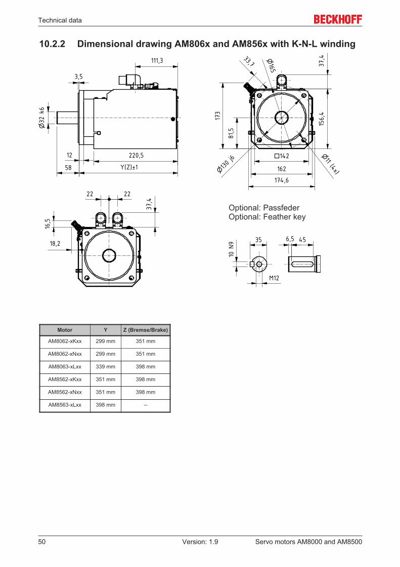
10.2.2 Dimensional drawing AM806x and AM856x with K-N-L winding

Technical data
Servo motors AM8000 and AM8500 51Version: 1.9
10.2.3 Dimensional drawing AM806x and AM856x with R-Q-T winding

Technical data
Servo motors AM8000 and AM850052 Version: 1.9
10.2.4 Radial / axial forces at the shaft end
10.2.5 Characteristic torque / speed curves
Note
Dimensioning software for motor characteristics:Characteristic torque / speed curves can be found on the Beckhoff-website under Motion.

Technical data
Servo motors AM8000 and AM8500 53Version: 1.9
10.3 AM807xTechnical data Symbol
[Unit]AM80xx
71M 71P 71T 72N 72R 72U 73P 73R 73U 74R 74T 74UElectrical data
Standstill torque* M0 [Nm] 42.8 42.8 41.2 80.7 80.7 74.0 104 104 95,0 129 129 129Standstill current Iorms [A] 12.6 23.8 41.1 16.1 29.2 53.0 19.8 37.4 66.5 25.8 49.4 69.2Max. mechanicalspeed
Nmax [min-1] 5000
Max. rated mainsvoltage
UN [VAC] 480
UN =115V
Rated speed Nn [min-1] 350 700 1400 200 400 1000 200 400 1000 250 500 750Rated torque* Mn [Nm] 41.1 39.2 36.6 79.9 78.3 62.3 98.2 95.8 76.5 122 115 106Rated output Pn [kW] 1.50 2.90 5.40 1.70 3.30 6.50 2.10 5.00 8.00 3,20 6,02 8,32
UN =230V
Rated speed Nn [min-1] 800 1500 2900 500 1000 2000 500 1000 2000 500 1000 1500Rated torque* Mn [Nm] 39.1 36.2 27.5 77.7 72.6 47.9 93.9 83.7 57.5 115 93,3 73,0Rated output Pn [kW] 3.30 5.70 8.00 4.10 7.60 10.0 5.00 8.80 12.0 6,02 9,77 11,46
UN =400V
Rated speed Nn [min-1] 1500 2900 4000 1000 2000 3000 1000 2000 3000 1000 2000 3000Rated torque* Mn [Nm] 36.2 29.2 18.1 72.6 60.1 33.8 83.7 63.3 17.8 93,3 51,7 24,5Rated output Pn [kW] 5.70 8.90 7.60 7.60 12.6 10.6 8.80 13.3 5.60 9,77 10,83 7,70
UN =480V
Rated speed Nn [min-1] 1700 3300 4500 1100 2200 3300 1100 2200 3000 1200 2200 3200Rated torque* Mn [Nm] 35.4 27.2 13.6 71.3 57.8 29.2 80.1 58.5 17.8 84,6 41,9 17,6Rated output Pn [kW] 6.35 9.33 6.40 8.20 13.3 10.1 9.30 13.6 4.50 10,63 9,65 5,90Peak current I0max [A] 25.9 49.0 81.8 36.3 66.1 120 51.3 97.4 180 66.7 129 180Peak torque M0max [Nm] 80.0 79.91 78.0 172.5 172.4 168.7 275 275.3 268 355 356 355Torque constant KTrms [Nm/A] 3.4 1.8 1.0 5.0 2.76 1.4 5.25 2.78 1.43 4.99 2.61 1.86Voltage constant KErms [mVmin] 231 122 70 328 180 92 347 183 104 343 177 127Winding resistance
Ph-Ph
R20 [Ω] 1.60 0.45 0.16 1.22 0.39 0.12 0.85 0.25 0.07 0.65 0.17 0.08
Winding resistance
Ph-Ph**
L [mH] 23.4 6.5 2.2 21.4 6.45 1.85 14.6 4.1 1.1 10.8 2.9 1.48
Connector plug M40-speedtec® T***
*reference flange aluminium 375 mm x 601 mm x 10 mm. **measured at 1kHz.*** = Terminal boxThe installation of a shaft seal ring leads to a reduction of the rated values.
Mechanical data AM8071 AM8072 AM8073 AM8074Rotor moment of inertia (without brake) J [kgcm2] 49,600 92,200 135,000Rotor moment of inertia (with brake) J [kgcm2] 68.300 111.000 154.000Pole number 10 10 10Static friction torque MR [Nm] 0.14 0.22 0.30Thermal time constant tTH [min] 70 80 90Weight (without brake) G [kg] 27.20 36.60 48.20Weight (with brake) G [kg] 32.70 42.10 53.70Permitted radial force at shaft end FR [N] see 10.7.2Permitted axial force FA [N]
Data of the power admission from the external fanSee chapter 8.3 “Connection of the fan with power admission”
Data for optional brake
Data Symbol [Unit] AM807xHolding torque at 120°C MBR [Nm] 70Supply voltage UBR [VDC] 24 +6 -10%Electrical power PBR [W] 40Current Ion [A] 1,21Release delay time tBRH [ms] 200Application delay time tBRL [ms] 50

Technical data
Servo motors AM8000 and AM850054 Version: 1.9
10.3.1 Dimensional drawing AM807x
Technical data
Servo motors AM8000 and AM8500 55Version: 1.9
10.3.2 Dimensional drawing AM8074

Technical data
Servo motors AM8000 and AM850056 Version: 1.9
10.3.2.1 Assignment planning of the Terminal box
Assignment planning Terminal CableB- 6B+ 5T- 8T+ 7PE Green/YellowW 3V 2U 1
10.3.3 Radial / axial forces at the shaft end
10.3.4 Characteristic torque / speed curves
Note
Dimensioning software for motor characteristics:Characteristic torque / speed curves can be found on the Beckhoff-website under Motion.

Support and Service
Servo motors AM8000 and AM8500 57Version: 1.9
11 Support and ServiceBeckhoff and their partners around the world offer comprehensive support and service, making available fastand competent assistance with all questions related to Beckhoff products and system solutions.
Beckhoff's branch offices and representatives
Please contact your Beckhoff branch office or representative for local support and service on Beckhoffproducts!
The addresses of Beckhoff's branch offices and representatives round the world can be found on her internetpages:http://www.beckhoff.com
You will also find further documentation for Beckhoff components there.
Beckhoff Headquarters
Beckhoff Automation GmbH & Co. KG
Huelshorstweg 2033415 VerlGermany
Phone: +49(0)5246/963-0Fax: +49(0)5246/963-198e-mail: [email protected]
Beckhoff Support
Support offers you comprehensive technical assistance, helping you not only with the application ofindividual Beckhoff products, but also with other, wide-ranging services:
• support• design, programming and commissioning of complex automation systems• and extensive training program for Beckhoff system components
Hotline: +49(0)5246/963-157Fax: +49(0)5246/963-9157e-mail: [email protected]
Beckhoff Service
The Beckhoff Service Center supports you in all matters of after-sales service:
• on-site service• repair service• spare parts service• hotline service
Hotline: +49(0)5246/963-460Fax: +49(0)5246/963-479e-mail: [email protected]