DOCUMENT RESUME ED 254 722 - ERICDOCUMENT RESUME ED 254 722 CE 040 998 TITLE Millwright...
287
DOCUMENT RESUME ED 254 722 CE 040 998 TITLE Millwright Apprenticeship. Related Training Modules. 8.1-8.5 Turbines. INSTITUTION Lane Community Coll., Eugene, Oreg. SPONS AGENCY Oregon State Dept.. of Education, Salem. PUB DATE [82] NOTE 295p.; For related documents, see CE 040 991-041 007. Many of the modules are duplicated in CE 040 985. PUB TYPE Guides - Classroom Use - Materials (For Learner) (051) EDRS PRICE DESCRIPTORS IDENTIFIERS MF01/PC12 Plus Postage. *Apprenticeships; Behavioral Objectives; Engines; Job Skills; Job Training; Learning Modules; Machine Tools; Mechanics (Physics); Postsecondary Education; *Power Technology; *Pressure (Physics); *Trade and Industrial Education *Millwrights; *Turbines ABSTRACT This packet, part of the instructional materials for the Oregon apprenticeship program for millwright training, contains five modules covering turbines. The modules provide information on the following topics: types, components, and auxiliaries of team turbines; operation and maintenance of steam turbines; and gas turbines. Each module consists of a goal, performance indicators, student study guide, vocabulary, introduction, information sheets illustrated with line drawings and photographs, an assignment sheet, a job sheet, a self-assessment test with answers, a post-assessment test with answers for the instructor, and a list of supplementary references. (Copies of supplementary references, which are sections of lectures from a correspondence course published by the Southern Alberta Institute of Technology, are included in the packets.) (KC) *********%************************************************************* Reproductions supplied by EDRS are the best that can be made from the original document. ***********************************************************************
Transcript of DOCUMENT RESUME ED 254 722 - ERICDOCUMENT RESUME ED 254 722 CE 040 998 TITLE Millwright...

DOCUMENT RESUME
ED 254 722 CE 040 998
TITLE Millwright Apprenticeship. Related Training Modules.8.1-8.5 Turbines.
INSTITUTION Lane Community Coll., Eugene, Oreg.SPONS AGENCY Oregon State Dept.. of Education, Salem.PUB DATE [82]NOTE 295p.; For related documents, see CE 040 991-041 007.
Many of the modules are duplicated in CE 040 985.PUB TYPE Guides - Classroom Use - Materials (For Learner)
(051)
EDRS PRICEDESCRIPTORS
IDENTIFIERS
MF01/PC12 Plus Postage.*Apprenticeships; Behavioral Objectives; Engines; JobSkills; Job Training; Learning Modules; MachineTools; Mechanics (Physics); Postsecondary Education;*Power Technology; *Pressure (Physics); *Trade andIndustrial Education*Millwrights; *Turbines
ABSTRACTThis packet, part of the instructional materials for
the Oregon apprenticeship program for millwright training, containsfive modules covering turbines. The modules provide information onthe following topics: types, components, and auxiliaries of teamturbines; operation and maintenance of steam turbines; and gasturbines. Each module consists of a goal, performance indicators,student study guide, vocabulary, introduction, information sheetsillustrated with line drawings and photographs, an assignment sheet,a job sheet, a self-assessment test with answers, a post-assessmenttest with answers for the instructor, and a list of supplementaryreferences. (Copies of supplementary references, which are sectionsof lectures from a correspondence course published by the SouthernAlberta Institute of Technology, are included in the packets.)(KC)
*********%*************************************************************
Reproductions supplied by EDRS are the best that can be madefrom the original document.
***********************************************************************

O
O
APPRENTICESHIP
. RELATEDTRAINING:. MODULES
f/ /- rUkbliVES
U.S. DEPARTMENT OF EDUCATIONNATIONAL INSTITUTE OF EDUCATION
EDUCATIONAL RESOURCES INFORMATION
CENTER (ERIC)"This document has been reproduced as
received from the person or organizationoriginating it
Minor changes have been made to improvereproduction quality
Points of view or opinions stated in this document do not necessarily rouresent official NIEposition or policy
"PERMISSION TO REPRODUCE THISMATERIAL HAS BEEN GRANTED BY
TO THE DUCATIONAL RESOURCESINFORMATION CENTER (ERIC)."

STATEMENT OF ASSURANCE
IT IS THE POLICY OF THE OREGON DEPARTMENT OF EDUCATION
THAT NO PERSON BE SUBJECTED TO DISCRIMINATION ON THE
BASIS OF RACE, NATIONAL ORIGIN, SEX, AGE, HANDICAP OR
MARITAL STATUS IN ANY PROGRAM, SERVICE OR ACTIVITY FOR
WHICH THE OREGON DEPARTMENT OF EDUCATION IS RESPONSIBLE,
THE DEPARTMENT WILL COMPLY WITH THE REQUIREMENTS OF STATE
AND FEDURAL LAW CONCERNING NON-DISCRIMINATION AND WILL
STRIVE BY ITS ACTIONS TO ENHANCE THE DIGNITY AND WORTH
OF ALL PERSONS,
STATEMENT OF DEVELOPMENT
THIS PROJECT WAS DEVELOPED AND PRODUCED UNDER A SUB-CONTRACT
FOR THE OREGON DEPARTMENT OF EDUCATION BY LANE COMMUNITY
COLLEGE, APPRENTICESHIP DIVISION, EUGENE, OREGON, ]9814.
LANE COMMUNITY COLLEGE IS AN AFFIRMATIVE ACTION/EQUAL
OPPORTUNITY INSTITUTION.

Pagel
APPRENTICESHIP
MILLWRIGHTRELATED TRAINING MODULES
SAFETY
1.1 General Safety1.2 Hand Tbol Safety1.3 Power Tool Safety1.4 Fire Safety1.5 Hygiene Safety1.6 Safety and Electricity1.7 Fire Types and Prevention1.8 Machine Safeguarding (includes OSHA Handbook)
ELECTRICITY/ELECTRONICS
2.1 Basics of Energy2.2 Atomic Theory2.3 Electrical Conduction2.4 Basics of Direct Current2.5 Introduction to Circuits2.6 Reading Scales2.7 Using a V.O.M.2.8 OHM'S Law2.9 Power and Watt's Law2.10 Kirchoff's Current Law
2.11 Kirchoff's Voltage Law2.12 Series Resistive Circuits2.13 Parallel Resistive Circuits2.14 Series - Parallel Resistive Circuits2.15 Switches and Relays2.16 Basics of Alternating Currents2.17 Magnetism
COMPUTERS
3.1 Digital Language3.2 Digital Logic3.3 Computer Overview3.4 Computer Software
TOOLS
4.1 Boring and Drilling Tools
4.2 Cutting Tbols, Files and Abrasives
4.3 Holding and Fastening Tools4.4 Fastening Devices
4.5 Basic Science - Simple Mechanics
4.6 Fasteners

DRAFTING
5.1 Types of Drawing and Views5.2 Sketching5.3 Blueprint Reading/Working Drawings5.4 Working Drawings for Machines and Welding5.5 Machine and Welding Symbols5.6 Blueprint Reading, Drafting: Basic Print5.7 Blueprint Reading, Drafting: Basic Print5.8 Blueprint Reading, Drafting: Basic Print5.9 Blueprint Reading, Drafting: Basic Print5.10 Blueprint Reading, Drafting: Basic Print5.11 Blueprint Reading, Drafting: Basic Print5.12 Blueprint Reading, Drafting: Basic Print5.13 Blueprint Reading, Drafting: Basic Print5.14 Drafting, Machine Features5.15 Drafting, Measurement5.16 Drafting, Visualization
HUMAN RELATIONS
6.1 Communications Skills6.2 Feedback6.3 Individual Strengths6.4 Interpersonal Conflicts6.5 Group Problem Solving6.6 Goal-setting and Decision-making6.7 Worksite Visits6.8 Resumes6.9 Interviews6.10 Expectation6.11 Wider Influences and Responsibilities6.12 Personal Finance
BOILERS
7.1 Boilers - Fire Tube Types7.2 Boilers - Watertube Types7.3 Boilers - Construction7.4 Boilers - Fittings7.5 Boilers - Operation7.6 Boilers - Cleaning7.7 Boilers - Heat Recovery Systems7.8 Boilers - Instruments and Controls7.9 Boilers - Piping and Steam Traps
8.1
8.2
8.3
8.4
8.5
TURBINES
Steam ThrbinesSteam ThrbinesSteam TurbinesSteam ThrbinesGas Turbines
- Types- Components- Auxillaries- Operation and Maintenance
ReadingReadingReadingReading
ReadingReadingReadingReading
Page II

Page III
PUMPS
9.1 Pumps - Types and Classification9.2 Pumps - Applications9.3 Pumps - Construction9.4 Pumps - Calculating Heat and Flow9.5 Pumps - Operation9.6 Pumps - Monitoring and Troubleshooting9.7 Pumps - Maintenance
COMBUSTION
10.1 Cambustion Process10.2 Combustion - Types of Fuel10.3 Combustion - Air and Fuel Gases10.4 Combustion - Heat Transfer10.5 Cambustion - Wbod
GENERATORS
11.1 Generators - Types and Construction11.2 Generators - Operation
FEECWATER
12.1 Feedwater - Types and Equipment12.2 Feedwater - Water Treatments12.3 Feedwater - Testing
AIR COMPRESSORS
13.1 Air Compressors - Types13.2 Air Compressors - Operation and Maintenance
STEAM
14.1 Steam - Formation and EvaporationSteam - Types
14 J Steam - Transport14.4 Steam - Purification
MISCELLANEOUS
15.1 Installation - Foundations15.2 Installation - Alignment15.3 Circuit Protection15.4 Transformers15.5 Trade Terms
TRADE MATH
16.1 Linear - Measure16.2 Whole Numbers16.3 Additional and Subtractidn of Common Fraction and Mixed Numbers16.4 Multiplication and Division of Common Fractions and Whole and
Mixed Numbers
6

16.5 Compound Numbers16.6 Percent16.7 Ratio and Proportion16.8 Perimeters, Areas and Volumes16.9 Circumference and Wide Area of Circles16.10 Area of Plane, Figures and Volumes of Solid Figures16.11 Metrics
17.117.2
17.3
17.4
17.5
17.617.7
17.8
17.917.1017.11
17.12
17.13
HYDRAULICS
Hydraulics -Hydraulics -Hydraulics -Hydraulics -Hydraulics -Hydraulics -Hydraulics -Hydraulics -Hydraulics -Hydraulics -
Hydraulics -Hydraulics -Hydraulics -
METALLURGY
LeverTransmission of ForceSymbolsBasic SystemsPumps
Pressure Relief ValveReservoirsDirectional Control ValveCylindersForces, Area, PressureConductors and ConnectorsTroubleshootingMaintenance
18.1 Included are ILS packets:W 3010W 3011-1W 3011-2MS 9001 (1-3-4-8-9-6-7-5-2-9)MS 9200, 9201
POWER DRIVES
19.1 101. A-B-C-D-E102. C-D-E103. B-C-D-E104. A-C -E-F -G -H -I -J
107. A108. A
WELDING
20.1 602. A-D-C -D-G -I -L -M
603. A-B -F-G -I
W. 3011-1 refer to Mettallurgy 18.1WE. MA-18
MILLWRIGHTSUPPLEMENTARY REFERENCE DIRECTORY
Note: All reference packets are numbered on the upper right-hand corner of the respective cover page.
SupplementaryPacket # Description Related Training Module
1.8 Concepts & Techniques of Machine Safeguarding, U.S.D.L., O.S.H.A. 1.8 Machine Safeguarding
12.1 Correspondence Course, Lecture 1, Sec. 2, Steam Generators, Types
of Boilers I, S.A.I.T., Calgary, Alberta, Canada
7.1 Boilers, Fire Tube Type
12.2 Correspondence Course, Lecture 2, Sec. 2, Steam Generators, Types
of Boikers II, S.A.I.T., Calgary, Alberta, Canada
7.2 Boilers, Water Tube Type
12.3 Correspondence Course, Lecture 2, Sec. 2, Steam Generators, Boiler 7,3 Boilers, Construction
Construction & Erection, S.A.I.T., Calgary, Alberta, Canada
12.4 Correspondence Curse, Lecture 4, Sec. 2, Steam Generators, Boiler 7.4 Boilers, Fittings
Fittings II, S.A.I.T., Calgary, Alberta, Canada
12.4 Corresponder.:e Course, Lecture 4, Sec. 2, Steam Generators, Boiler 7.4 Boilers, Fittings
Fitting I, S.A.I.T., Calgary, Alberta, Canada
12.5 Correspondence Course, Lecture 10, Sec. 2, Steam Generation, Boiler 7.5 Boilers, Operation
Operation, Maintenance, Inspection, S.A.I.T., Calgary, Alberta,
Canada
12.7 Correspondence Course, Lecture 3, Sec. 2, Steam Generation, Boiler 7.7 Boilers Heat Recovery
Details, S.A.I.T., Calgary, Alberta, Canada Systems
PUMPS
13.1 Correspondence Course, Lecture 9, Sec. 2, Steam Generator, Power Types & Classifications
13.2 Plant Pumps, S.A.I.T., Calgary, Alberta, Canada 9.2 Applications
13.49.4 Calculating Heat & Flow
13.69.6 Monitoring & Troubleshooting
13.79.7 Maintenance
13.3 Correspondence Course, Lecture 6, Sec. 3, Steam Generators, Pumps, 9.3 Construction
13.5 S.A.I.T., Calgary, Alberta, Canada 9.5 Operation

MillwrightSupplementary Reference DirectoryPage 2 BEST COPY AVAILABLE
SupplementaryPacket # Description
14.3 Correspondence Course, Lecture 6, Sec. 3, Steam Generators, Steam
12.8 Generator Controls, S.A.I.T., Calgary, Alberta, Canada
14.4 Correspondence Course, Lecture 11, Sec. 2, Steam Generators,
Piping II, S.AI.T., Calgary, Alberta, Canada
15.1 Correspondence Course, Lecture 1, Sec. 4, Prime Movers, & Auxil-iaries, Steam Turbines, S.A.I.T., Calgary, Alberta, Canada
15.2 Correspondence Course, Lecture 4, Sec. 3, Prime Movers, SteamTurbines I, S.A.I.T., Calgary, Alberta, Canada
15.3 Correspondence Course, Lecture 2, Sec. 4, Prime Movers & Auxil-
iaries, Steam Turbine Auxiliaries, S.A.I.T., Calgary, Alberta,
Canada
15.4 Correspondence Course, Lecture 6, Sec. 3, Prime Movers, SteamTurbine Operation & Maintenance, S.A.I.1., Calgary, Alberta,Canada
15.5 Correspondence Course, Lecture 8, Sec. 3, Prime Movers, GasTurbines, S.A.I.T., Calgary, Alberta, Canada
16.2 L'doilers Fired with Wood & Bait Pesidues, D.D. Junge, F.R.L.,U.S.U., 1975
16.2 ,,,rrespondeuce Course, Le,:ture 5, Sec. 2, Steam Generators, Fuelr:ombustion, S.A.I.T., Calgary, Alberta, Canada
16.3 (:orrespondence Course, Lecture 5, Sec. 2, Plant Services, FuelCombustion, S.A.I.T., Calgary, Alberta, Canada
17.1 Correspondence Course, Lecture 12, Sec. 3, Steam Generation, WaterTreatment, S.A.I.T., Calgary, Alberta, Canada
L 2 Correspondence Course, Lecture 12, Sec. 2, Steam Generation, WaterTreatment, S.A.I.T., Calgary, Alberta, Canada
Related Training Module
14.3 Steam Transport
7.8 Boilers, Instruments &Controls
14.4 Steam Purification
8.1 Steam Turbines, Types
8.2 Steam Turbines, Components
8.3 Steam Turbines, Auxiliaries
8.4 Steam Turbines, Operation& Maintenance
8.5 Gas Turbines
10.2 Combustion Types of Fuel
10.2 Combustion Types of Fuel
10.3 Combustion Air & Fuel Gases
12.1 Feedwater, Types &0p-ration
12.2 Feedwater, WaterTreatments
11

MillwrightSupplementary Reference Directory
Page 3
SupplementaryPacket # Description
Related Training Module
17.3 Correspondence Course, Lecture 7, Sec. 2, Steam G aerators, Boiler 12.3 Feedwater, Testing
Feedwater Treatment, S.A.I.T., Calgary, Alberta, c. nada
18.1 Correspondence Course, Lecture 2, Sec. 5, Electricity, Direct 11.1 Generators, Types &
Current Machines, S.A.I.T., Calgary, Alberta, Canada Construction
18.1 Correspondence Course, Lecture 4, Sec. 5, Electricity, Alternating 11.1 Generators, Types &
18.2 Current Generators, S.A.I.T., Calgary, Alberta, Canada Construction18.2 Generators, Operation
19.1 Correspondence Course, Lecture 5, Sec. 4, Prime Movers & Auxil-
iaries, Air Compressor I, S.A.I.T., Calgary, Alberta, Canada
13.1 Air Compressors, Types
19.1 Correspondence Course, Lecture 6, Sec. 4, Prime Movers & Auxil- 13.1 Air Compressors, Types
iaries, Air Compressors II, S.A.I.T., Calgary, Alberta, Canada 13.2 Air Compressors, Operation& Maintenance
20.1 Basic Electronics, Power Transformers, EL-BE-51 15.4 Transformers
21.1 Correspondence Course, Lecture 6, Sec. 5, Electricity, Switchgear 15.3 Circuit Protection
& Circuit, Protective Equipment, S.A.I.T., Calgary, Alberta,
Canada
22.1 Correspondence Course, Lecture 10, Sec. 3, Prime Movers, Power 15.1 Installation Foundations
Plant Erection & Installation, S.A.I.T., Calgary, Alberta, Canada

RECOMMENDATIONS FOR USING TRAINING MODULES
The following pages list modules and their corresponding numbers for this
particular apprenticeship trade. As related training classroom hours
vary for different reasons throughout the state, we recommend that
the individual apprenticeship committees divide the total packets to
fit their individual class schedules.
There are over 130 modules available. Apprentices can complete the
whole set by the end of their indentured apprenticeships. Some
apprentices may already have knowledge and skills that are covered
in particular modules. In those cases, perhaps credit could be
granted for those subjects, allowing apprentcies to advance to the
remaining modules.
We suggest the the apprenticeship instructors assign the modules in
numerical order to make this learning tool most effective.

SUPPLEMENTARY INFORMATION
ON CASSETTE TAPES
Tape 1: Fire Tube Boilers - Water Tube Boilersand Boiler Manholes and Safety Precautions
Tape 2: Boiler Fittings, Valves, Injectors,Pumps and Steam Traps
Tape 3: Combustion, Boiler Care and Heat Transferand Feed Water Types
Tape 4: Boiler Safety and Steam TUrbines
NOTE: The above cassetterefe:ence materialindi:ated, and not
tapes are intended as additionalfor the respective modules, asdesignated as a required assignment.

Modules 18.1, 19.1, and 20.1 have been omitted because they containdated materials.

WWWW011AL LEAVIVIC MOWit)
8.1
STEAM TURBINES -- TYPES
Goal:
The apprentice will be able todescribe the common types ofsteam turbines.
1
=11111111111r
17
Performance Indicators:
1. Describe impulse turbines.
2. Describe reaction turbines.
3. Describe compound turbines.
4. Describe velocity blading.
5. Describe reaction blading.
6. Describe turbine compounding.
7. Describe other types ofturbines.

INSTRUCTIONAL LEARNING SnILAAS
Study Guide
Read the goal and performance indicators to find what is to be learned from
package.
Read the vocabulary list to find new words that will be used in package.
Read the introduction and information sheets.
* Complete the job sheet.
Complete self-assessment.
Complete post-assessment.
2
valmENEMINNIMMI .=1=Inmlomma
ld

'Ma 1 riu1.#1 Lprmilitioa 33:1_9_11.-1V1%)
°Vocabulary
Compound turbines
Condensing turbine
Condensing bleeder turbine
Cross compound turbine
Extraction turbines
Impulse turbines
Kinetic energy
Pressure compounding
Pressure velocity compounding
Reaction blading
Reaction turbine
Tandem compound turbine
Turbine compounding
Velocity blading

INSTRUCTIONAL LE,AliNINU I EMS
°Introduction
Turbines are. a type of motor that is mounted on a shaft and consists of rotor
blades that are actuated by steam, gas, water or other pressure. The steam
turbine is common to the American industrial setting.
Basically, turbines operate on the principles of impulse and reaction. Turbine
design uses these principles, singly and in combination,*to improve the
efficiency of turbines.
Efficiency involves capturing most of the force or energy of the steam that
passes through the turbine blades. Several methods of "Compounding" this energy
have been incorporated into the design of turbine engines.
4
20)

INSTRUCTIONAL LEARNING SYSTEMS
InformationThe steam turbine is used by industries where power and heat is needed to performprocessing. Refineries, paper mills, food processing, heating plants and manyother industries utilize steam turbines as a prime mover.
Impulse Turbines'
The impulse turbine uses stationary steam nozzles to turn a rotor with blades orbuckets. Steam is directed at high velocity at the blades. The high velocityof the steam is a result of lowered steam pressure. As steam pressure is
reduced the heat energy of the steam is converted into kinetic energy. Theblades of the rotor convert the kinetic energy into mechanical energy whichturns the rotor and shaft. The impulse principle can be shown.
FORCE'F'
LEADINGEDGE ATEAM
IN
%41,tOUTSTEAM
Section of Turbine Blade
The velocity increases and pressure drops as the steam passes through the
nozzles. As the steam passes through the blades, the velocity drops but
pressure remains constant.. On impulse turbines, pressure at the inlet to bladesis the same as that at the outlet from the blades.
Reaction Turbine
In the pure form, reaction turbines are not used in industry. The reactionturbine that is common uses the principles of impulse and reaction. There are
equal numbers of rows of fixed and rotating blades on the rotor. The steam
velocity increases as it passes through the fixed blades. As it strikes the
fixed blades, the pressure of the steam is reduced and velocity increased due toa change in direction. This produces a driving force in the same manner as on
impulse turbine. The steam will next undergo a reaction process. The rotatingblades are arranged in a manner that will allow the pressure to drop. Remember,
in the impulse turbine the pressure remains the same as it passes through the
5
21

INSTRUCTIONAL LEARNING SYSTEMS--
Informationblades. In a reaction turbine, this pressure drop allows more heat energy to beconverted into a driving force. The reaction turbine has a driving force equ_ .
to the energy converted by impulse and that from the reaction. In both cases,
the pressure drop. increased velocity; converted heat energy to kinetic energy;
and converted kinetic energy into mechanical energy for turning the rotor.
Commercial turbines are often a combination of impulse and reaction types.
Compound Turbines
Compound turbines consist of two or more large turbines linked with one or moregenerators. A ricoriltanderidturbine is two or more turbines hooked in series
with one gerneator. A cross compound turbine is a coupling of turbines in whicheach is on its own shaft and has its own generator. The steam flows from one tothe other.
TANOEM-COMPOUND TURBINE CROSS-COMPOUND TURBINE
Velocity Blading
Velocity blading is a method of reducing steam velocity from boiler pressure to
exhaust pressure. Steam is expanded within one set of nozzles and routed
through rows of moving and fixed blades. The steam velocity is absorbed in themoving blades. The fixed blades act to redirect the steam to the next rowof moving blades. Since the velocity is absorbed by several rows of moving
blades, the blade speed is less than if the velocity'was absorbed by a single
row of blades. Velocity blading is a method for reducing the speed of the
rotor. For maximum efficiency, the blade velocity should be one half that of
the steam velocity.
0
22
-INSTRUCTIONAL LEARNING SYSTEMS
°Information
1114011W
Reaction Blading
Reaction blading uses the principles of impulse and reaction turbines to pullthe maximum energy from the steam. As sLeam expands in the fixed blades,velocity increases and the pressure drops. The increased velocity hits themoving blades and exerts a force on the rotor. The steam will continue toincrease and decrease pressure and velocity as it passes through alternatingrows of fixed and moving blades. This type of blading "milks" the last drop ofenergy from the passing steam.
Turbine Compounding.
Turbine design attempts to utilize all of the kinetic energy available in steamas it passes through the blades. A number of methods are used to capture theenergy. Most are based upon the principle that when steam expands, the velocityincreases. Three basic methods for compounding the energy of steam are utilizedin the design of turbines.
1. ?ressure compounding2. Velocity compounding3. Pressure-velocity compounding
Pressure compounding drops the steam pressure in stages. The pressure dropsoccur as steam passes through nozzles. This system uses several nozzles thatare fitted into diaphragms to keep each stage of compounding separate from theothers. As the steam moves into each row of blades, the blade speed is reduced.To get the proper blade speed, additional stages can be added.
Velocity compounding uses, one set of nozzles and several rows of fixed andmoving blades. As steam passes from stationary to moving blades, a change of
direction of energy occurs. Velocity is absorbed by more than one row of movingblades. The blade velocity is reduced to a ratio of maximum efficiency. Somesmall turbines have only single wheels and use return guides or reversingchambers to change direction of steam and force it to give up its useful energy.The singel wheel types are axial re-entry or radial re- entry turbines.
Pressure-velocity Compounding
This system of compounding utilizes the principles of pressure and velocitycompounding. Velocity compounded turbines are arranged in series on the sameshaft. h number of sets of nozzles are added to give the desired pressure drop.
7
23

--INSTRUCTIONAL LEARNINGSYSTEMS-
nformationOther Classifications and Tines of Turbines
Condensing turbines exhausts steam to a condenser where the heat of the steam istransferred to the cooling water and returned to the boiler. A condensing-
bleeder turbine has places for bleeding off the steam at various points. The
bleed steam is used for heating the feedwater.
Extraction turbines allow steam to be extracted at one or more points. The
extracted steam can be used for purposes other than heating feedwater as in thecase of bleeder turbines.
Condensing Turbines
Condensing turbines operate in conjunction with a condenser. The exhaust
pressure is reduced below that of atmospheric pressure. The condenser changes
0 the exhaust steam to water and returns it as boiler feedwater.
Non-condensing Turbines
Small turbines often discharge the steam exhaust into the atmosphere or uses itas process steam. When steam is not returned to the boiler it is called.a non-condensing turbine. Condensers are not part of a non-condensing turbine.

- -*-:INS I KUL; FIUNAL LcAtiNtivta0 L i PENN)
Assignment
Read pages 1 - 12 in supplementary reference.
Complete job sheet.
Complete self=assessment and check answers with answer sheet.
Complete post-assessment and ask instructor to check your answers.
9

-INSTRUCTIONAL LEARNING-SYSTEMS -.1011
Sheet
ANALYZE TURBINE SPECIFICATIONS
Obtain turbinb specifications from a supply catalog, equipment manual or
other source.
Read and analyze the specifications of a specific model turbine.
- Is the turbine an impulse or reaction turbine?
- Is it a condensing, non-condensing, extraction, bleeder turbine?
- How is the turbine compounded?
Ask instructor to explain those features that you do not understand.
10
26

SiINSTRUCTIONAL LEARNING SYSTEMS
-1111MMIMIMIV.
.SelfAssessmentMatch the following turbine terms with appropriate phrases.
1. Impulse turbine A. Method of reducing steamvelocity.
2. Tandem compound turbine B. Drops steam pressure instages.
3. Reaction turbine C. Exhausts steam to a condenser.
4. Cross compound turbine D. Converted from heat energy aspressure of steam is reduced.
5, Velocity compounding E. Energy that turns the rotor.
6. Pressure compounding F. Stationary steam nozzles.
7. Mechanical energy G. Allows steam to be extractedat various points in turbine.
8. Condensing turbine H. Not used in pure form byindustry.
9. Kinetic energy I. Two or more turbines in serieswith one generator.
10. Extraction turbine J. Two or more generators on theirown shaft and with their owngenerator but using the samesteam.
11
27

molituv.filuroit.t.r.Artivili%L.o..t*Lcsio
Self AssessmentAnswers
1. F
2. I
3. H
4. J
5. A
6.
7. E
8. C
9. D
10. G
12

INSTRUCTIONAL-LEARNINGSYSTEMS-
PostAssessment
Mark the following statements (Tor F) true or false.
1. Reaction turbines in their pure form are not used in industry.
2. The so called reaction turbines use both impulse and reactionprinciples.
3. As steam expands in the nozzles pressure drops.
4. Velocity increases as steam pressure is reduced.
5. A cross-compound turbine is a series of turbines mounted on asingle shaft with one generator.
6. Velocity blading is a method of increasing the speed of the rotor.
7. Velocity compounding reduces steam pressure through a series ofstages or nozzles that are separated by diaphragms.
8. Condensing turbines return their exhaust steam as feedwaterto the boiler by running it through a condenser.
9. Extraction turbines allow steam to be pulled from the turbine forother purposes such as steam cleaning.
10. Axial re-entry turbines are a large type of turbine.
13
2J

INSTRUCTIONAL-LEARNING-SYSTEMS-- ------
InstructorPost AssessmentAnswers
1. T
2. T
3. T
4. T
5. F
6. F
7. F
8. T
9. T
10. r'
14
=11=IMI
30
-INSTRUCTIONAL LEARNING -SYSTEMS-
SupplementaryReferences
* Correspondence Course. Lecture 1, Section 4, Third Class. Southern
Alberta Institute of Technology. Calgary, Alberta, Canada.
o

SOUTHERN ALBERTA INSTITUTE OF TECHNOLOGYCALGARY, ALBERTA
Correspondence CoursesPower Engineering
SECTION 4
PRIME MOVERS AND AUXILIARIES
STEAM TURBINES
INTRODUCT1uN
15.1
Third ClassLecture 1
Of all heat engines and prime movers the steam turbine is nearest to theideal and it is widely used in power plants and in all industries where powerand/or heat is needed for processes. These include: pulp mills, refineries,petro-chemical plants, food processing plants, desalination plants, refuseincinerating and district heating plants.
Advantages
The successful application in so many industries is due to the manyideal features of the steam turbine. These features include:
1. Ability to utilize high pressure and high temperature steam,
2. High efficiency.
3. High rotational speed.
4. High capacity/weight ratio,
5. Smooth, nearly vibration-free operation.
6. No internal lubrication.
7. Oilfree exhaust steam,
H. Can be built in small or very large units ( up to 1200 MW ).
3

- 2 -
Disadvantages
The few disadvantages of the steam turbine are:1. For slow speed application reduction gears are required.2. The steam turbine cannot be made reversible,3. The efficiency of small simple steam turbines is poor.
OPERATION PRINCIPLES
Impulse Turbine
In principle the impulse steam .arbine consists of a casing containingstationary steam nozzles and a. rotor with moving or rotating buckets.
The steam passes through the stationary nozzles and is directed at highvelocity against the rotor buckets causing the rotor to rotate at high speed.
The following events take place in the nozzles:
The steam pressure decreases.
The enthalpy of the steam decreases.
The steam velocity increases.
The volume of the steam increases.
There is a conversion of heat energy to kinetic energy as the heat energyfrom the decrease in steam enthalpy is converted into kinetic energy by the in-creased steam velo'city.
The nozzles may De convergent nozzles ( Fig. 1) or they may be con-vergent-divergent nozzles Fig. 2 ), Convergent nozzles are used for smallerpressure drops where the minimum exit pressure is 0.577 x the inlet pressure( the critical pressure for nozzles, ).
If the exit pressure is less than 0.577 x inlet pressure, eddy-currentsare developed and the exit velocity will be less than calculated.
The convergent - divergent nozzles prevent eddy-currents and the cal-culated velocity will be obtained even at large pressure drops,
1)1. ,', 1-1 2i
33

1
ENTRANCE FLOW EXIT
ENTRANCE
THROAT
Convergent Nozzle
Fig. 1
FLOW EXIT
CONVERGENTSECTION
DIVERGENTSECTION
Convergent-DivergentNozzle
Fig. 2.
The purpose of the bucket or moving blade on the rotor is to convert thekinetic energy of the steam into mechanical energy. If all kinetic energy is con-verted the steam exit velocity will he 0 m/s. This is not possible but it showsthat the rotor blades must bring the steam exit velocity near 0 m/s.
I.'
3 4
( P1.3-4-1-3)

4
The Impulse Prthi)iple
If steam at high pressure is allowed to expand through a stationarynozzle, the result will be a drop in the steam pressure and an increase in steamvelocity. In fact, the steam will issue from the nozzle in the form of a high speedjet. If this high velocity steam is applied to a properly shaped turbine blade, itwill change in direction due to the shape of the blade ( Fig. 3 ). The effect of thischange in direction of the steam flow will be to produce an impulse force, markedF in Fig, 3, on the blade causing it to move, If the blade is attached to the rotorof a turbine, then the rotor will revolve.
FORCE
LEADINGEDGE 1LTE
NAM
I
STEAM1,kOUT
Section of Turbine Blade
Fig. 3
In Fig. 3, force applied tc the blade is developed by causing the steam tochange direction of flow ( Newton's 2nd Law change of momentum ). The changeof momentum produces the impulse force.
In an actual impulse turbine there are a number of stationary nozzles andthe moving blades are arranged completely around the rotor periphery.
Fig. 4 shows the nozzle and blade arrangement in a simple impulseturbine and the graph in the figure indicates how the pressure and the velocity ofthe steam change as the steam passes through first the stationary nozzles andthen the moving blades.
Note that the pressure drops and the velocity increases as the steampasses through the nozzles. Then as the steam passes through the moving bladesthe velocity drops but the pressure remains the same.
The fact that the pressure does not drop across the moving blades is thedistinguishing feature of the impulse turbine. The pressure at the inlet to themoving blades is the same as the pressure at the outlet from the moving blades.
1)1..3-4-1-.1

- 5
IN INNOZZLE BLADES
VELOCITY OFSTEAM LEAVING
CONDENSERPREsSURE
SHROUD CLEARANCE
LIVE STEAMENTERING
EXHAUST
STEAMLEAVING
BLADE
ROTOR
CASING
BEARING
Simple Impulse Turbine
Fig, 4
The Reaction Principle
If the moving blades of a turbineare shaped in such a way that the steamexpands and drops in pressure as itpasses through them, then a reactionwill be produced which gives a force tothe blades, This reaction effect can beillustrated by considering a containerfilled with high pressure steam as inFig, 5,
If there is no escape opening ornozzle for the steam, then the pressurewill be the same on all walls of the con-tainer and the container will remain atrest, If, however, the container has anescape opening or nozzle, then steam willexpand through the opening and drop inpressure, As a result there will be anunbalanced pressure on the wall opposite tothe opening and a reaction force R willbe produced causing the container to move,
36
Reaction Effect
Fig, 5
(

- 6 -
Pure Reaction Turbine
Fig. 6
Fig, 6 shows a diagram of this principle applied to a turbine drive.
A reaction turbine has rows of fixed blades alternating with rows ofmoving blades. The steam expands first in the stationary or fixed blades where itgains some velocity as it drops in pressure. It then enters the moving bladeswhere its direction of flow is changed thus producing an impulse force on the mov-ing blades. In addition, however, the steam upon passing through the movingblades, again expands and further drops in pressure giving a reaction force to theblades.
This sequence is repeated as the steam passes through additional rowsof fixed and moving blades,
Fig. 7 shows the blade arrangement and the pressure and velocity changesof the steam in a reaction turbine.
Note that the steam pressure drops across both the fixed and the movingblades while the absolute velocity rises in the fixed blades and drops in the movingblades.
The distinguishing feature of the reaction turbine is the fact that thepressure does drop across the moving blades. In other words there is a pressure
)

,IN MOVIN$W.ADE4111.14.4
ItUIN iTATL
IdOTARY
" i I 1,1, VELOCITY OF/641 STFAM LEAVING
I CONDENSERPRESSURE
I 1 11 11
1, IS I 1$ I
...40 I "kb
MOVINGBLADES
CLEARANCE
LIVE STEAMENTERING
UST
ST AMLEAVING
CASING
ARING
Simple Reaction Turbine
Fig. 7
difference between the inlet to the moving blades and the outlet from the movingblades.
Special Aspects of Rea Ction Turbines
1. There is a difference in pressure across the moving blades.The steam will therefore tend to leak around the periphery of theblades instead of passing through them. Blade clearances thereforemust be kept to a minimum.
2. Also, due to pressure drop across the moving blades, an unbalancedthrust will be developed upon the rotor and some arrangement mustbe made to balance this.
3d
( 1 )1.;:i -.1 1 -7 )

Impulse Turbine Staging
In order for the steam to give up all its kinetic energy to the movingblades in an impulse turbine, it should leave the blades at zero velocity. This con-dition will exist if the blade velocity is equal to one half of the steam velocity.Therefore, for good efficiency the blade velocity should be about one half of thesteam velocity.
If the steam was expanded from admission pressure down to final exhaustpressure in a single set of nozzles ( single stage ) then the velocity of the steamleaving the nozzles might be in the order of 1100 m per s. In order to havegood efficiency the blade velocity would have to be about 550 m per s., whichwould require excessively high rev/min of the turbine rotor and failure due tocentrifugal force could result.
In addition to this objection, excessively high steam velocity will causehigh friction losses in nozzles and blading.
In order to reduce steam velocity and blade velocity, the followingmethods may be used:
Pressure compounding,2. Velocity compounding,
3. Pressure-velocity compounding.
1. Pressure Compounding
The expansion of steam from boiler pressure to exhaust pressure iscarried out in a number of steps or stages. Each stage has a set of nozzles anda row of moving blades. The rows of moving blades are separated from eachother by partitions or diaphragms into which the nozzles are set. As only a por-tion of the velocity available is developed in each set of nozzles, the blade velocityis kept down to a reasonable amount.
This type of compounding is known as the Bateau method and the nozzleand blade arrangement for a pressure compounded impulse turbine is sketched inFig. 8.
in this arrangement, the pressure of the steam drops in each set ofnozzles as indicated by the pressure graph. The steam velocity is increased byeach pressure drop and then decreases again in each row of moving blades, asthe velocity graph shows.
; 1 - )
3 9

IN INrim puhcfsr Ili i
12 Lail1
I
si* I
o!- r VELOCITY OF
44.0 I I I STEAM LEAVINGW
Sr Z to'il 'CONDENSER
E; §'P I PRESSUREI
Et .., 41"- ..
-al
LIVE STEAM
DIAPHRAGM
BLADE
ENTERING
W
11 CASING
HEEL
B
Mill=111111011
CL EAR ANCL
EXHAUST
STCaEAVING
ARING
Pressure Compounded Impulse Turbine
Fig. 8
2, Velocity Compounding
,/ 7ON MOVING BLADE s
- ,....e, NCIIt I STATIONARY I I
i p a r . . 1 I I
p.:,,J 1 VELOCITY OFI (STEAM LEAVINGII CONDENSER11 PR6SSURE
IIII
MOVINGBLADES
CLEARANCE
LIVE STREAMENTERING
E XHAU§T
STEAMLEAVING
STATIONARYBLADES
SING
BEARING
10111MMINIM
Velocity Compounded Impulse Turbine
NI, 9
This design consists of one set of nozzles in which the steam is expandedfrom initial to exhaust pi.essure. The velocity of the steam resulting from thisexpansion is absorbed in two or more rows of moving blades. Rows of fixed orguide blades, attached to the easing, are set between the rows of moving bladesand receive and redirect the steam to the next row of moving bladeS. As thevelocity is absorbed in more than one row of moving blades, the blade speed isless than if the velocity was all absorbed in one row of blades.
This type of compounding is known as the Curtis method and the bladeand nozzle arrangement for a velocity compounded impulse turbine is shown inFig. 9.
PE3-1-1-9
..uPY AVAILABLE
4 0

- 10 -
The pressure drops from inlet pressure to exhaust pressure in the singleset of nozzles as the pressure graph shows. This large single pressure drop pro-duces high steam velocity which is absorbed in the two rows of moving blades,Note that there is no pressure or velocity drop in the fixed guide blades,3, Pressure-Velocity Compounding
This is a combination of the first two methods of compounding, namelypressure compounding and velocity compounding.
The steam is expanded in two or more sets of nozzles in series, eachset having velocity compounded blades to receive the steam issuing from thenozzles.
The arrangement shown inFig. 9 ( a) features two sets of nozzles.The steam pressure drops in each setof nozzles and the resulting velocity in-crease in each case is absorbed by tworows of moving blades having a row ofstationary blades between them.
The methods of reducing rotorspeeds, namely, pressure compounding,velocity compounding, and pressure-velocity compounding have all applied toimpulse turbines,
In the case of the reaction tur-bine, it is not necessary to make specialblade arrangements to reduce rotorspeed. This is because the pressuredrops across each row of moving bladesas well as across each row of fixedblades and consequently the pressuredrops in even stages and small amountsall through the machine. This requires,however, a large number of alternaterows of fixed and moving blades re-sulting in a long machine. Therefore,in order to reduce the number of bladerows necessary, reaction turbines frequently have a velocity compounded impulsestage at the inlet end of the machine.
INNOZZLE IN NOZZLE,IN MOVING 'LADES IIIN MOVING BLADESr 'I,, I IN
STATIONARY, I SITAT410 I I IIMAD1I # 1VELOCITY OF
1 ;T Er LEAVING
,PILAJ5f11
1 II Is.1
iiPBEISUR
II I I
tiI I
1 1 IsI I
I TAG E I 7t --21' Sat
ICONDENSEIPRESSURE!
MOVINGBLADE
CLEARANC
1(ES1 LAMENTERING
DIAPHRAGM
EXHAUST
STEAMLEAVING
STATIONARYBLADES
CASING
BEARING
Pressure-Velocity Compounded ImpulseTurbine
Fig. 9 ( a
41

TYPES OF TURBINES
Condensing_Turbines
With the condensing turbine the steam exhausts to the condenser and thelatent heat of the steam is transferred to the cooling water. The condensed steamis returned to the boiler as feedwater.
Condensing-Bleeder Turbines
The condensing-bleeder turbine reduces the condenser losses as steamis bled off at several points of the turbine. The bleed-steam is used for feedwaterheating; up to 20% of the total steam flow may be bled off.
Back-Pressure Turbines
Back-pressure turbines are often used in industrial plants, the turbineacts as a reducing station between boiler and process steam header. The processsteam pressure is kept constant and the generator output depends on the demandfor process steam.
The back-pressure turbine may also have bleed points and is then calleda back-pressure-bleeder-turbine.
Ext raction Turbines
Extraction turbines are turbines where steam is extracted at one or morepoints at constant pressure.
Extraction turbines may be single or double-extraction-condensing tur-bines or single-or double-extraction back-pressure turbines. The extractionturbines may, besides extraction points, have bleed points for feedwater heating.
Topping; Turbines
Topping turbines have been used when old boilers are replaced with newhigh pressure boilers. The turbine is a back-pressure turbine exhausting to theold boiler header still supplying steam to the old lower pressure turbines.
Mixed pressure Turbines
Mixed pressure turbines are used where excess steam from process isavailable for the low pressure part of the turbine, while steam at boiler pressuremay he added to the high pressure part of the turbine when more load is appliedto the turbine,
1'1%3 -1- 1 -1 1 )
12 -
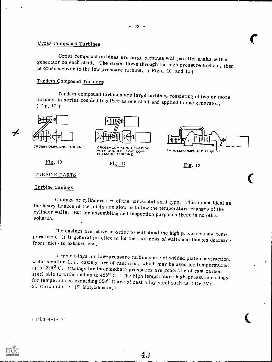
Cross Compound Turbines
Cross compound turbines are large turbines with parallel shafts with agenerator on each shaft. The steam flows through the high pressure turbine, thenis crossed-over to the low pressure turbine. ( Figs. 1.0 and 11 )
Tandem Compound Turbines
Tandem compound turbines are large turbines consisting of two or moreturbines in series coupled together as one shaft and applied to one generator.( Fig. 12 )
CROSSCOMPOUNO TURBINE
Fig. 10
TURBINE PARTS
Turbine Casings
CROSS-COMPOUND TURBINEWITH DOUBLEFLOW LOW.PRESSURE TURBINE
Fig, 1.1
TANDEMCOMPOUND TURBINE
Fig. 12
Casings or cylinders arc of the horizontal split type. This is not ideal asthe heavy flanges of the joints are slow to follow the temperature changes of thecylinder walls. But for assembling and inspection purposes there is no othersolut ion.
The casings are heavy in order to withstand the high pressures and tem-peratures. It is general practice to let the thickness of walls and flanges decreasefrom inlet- to exhaust-end.
Large casings for low-pressure turbines are of welded plate construction,while smaller L.P. casings are of east iron, which may be used for temperaturesup to 230° C. Casings for intermediate pressures are generally of cast carbonsteel able to withstand up to 425° C. The high temperature high-pressure casingsfor temperatures exceeding 550° C are of cast alloy steel such as 3 Cr 1Mo
(3',;('. Chromium 1% Molybdenum.)
( PE3 I -1-12 )

- 13
The reason for using different casing materials is that materials at thegiven maximum temperatures and under constant pressure continue to deformwith very slowly increasing strain of the material; this phenomenon is called" Creep ".
The casing joints are made steam tight, without the use of gaskets, bymatching the flange faces very exactly and very smoothly. The bolt holes in theflanges are drilled for smoothly fitting bolts, but dowel pins are often added tosecure exact alignment of the flange joint. The assembled casing is then machinedoff inside on a boring-mill, where grooves are made for the diaphragms ( forimpulse turbines ) or for the stationary blades ( reaction turbines ). Borings arealso made for shaft seals and in many cases for the bearings also.
For high pressures theflanges of the casings must bevery heavy and will heat up muchslower than the casing walls.Flange heating, by steam throughmachined channels between theflanges or holes drilled axiallythrough the upper and lowerflanges, is often applied.( Fig. 13 ).
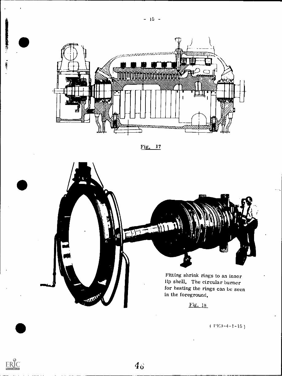
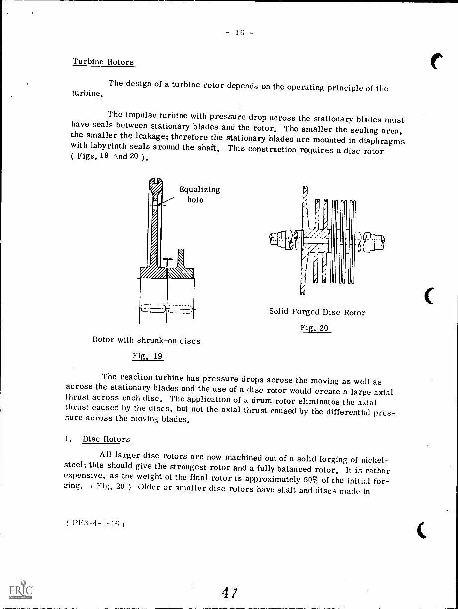
Double casings are usedfor very high steam pressures.( Figs. 15 and 16) The highpressure is applied to the innercasing, which is open at theexhaust end, letting the turbineexhaust to the outer casings;the pressure is divided betweenthe casings, and most important,the temperature is also dividedand thermal stresses on casingsand flanges are greatly reduced.Radiation losses are also decreased.The inner casing may be assembledwith shrink rings giving an idealcasing without flanges ( Figs. 17 and
Flg. 18. Flange warming
The hot slemn flows through the Space between the bearif,gof the lidr.;se And is forced to flow round the bolt by means of hallli
plates
a
18 ).
4 4
I Ring(' bearing c Baffle 1 OutsideI .uriaces plates 2 Inside
Fig. 13
( PE3-4-1-13 )
BEST COPY AVAILABLE

- 14 -
( 1'E3-4-1-14
Cross-section through a valvecasing with four valves and thewheel-chamber of an industrialturbine.
Fig. 14
Cross-section through Double-shell lip Turbire
Fig, 15
Oil
frf
I 4.w41
VIT111111111TI!\IMP I 1111 k11111111.61111 III 1 w 141111
, , $
111/41g, zee dzehr7$
./
I
://1
,
44.
Turbine Rotors
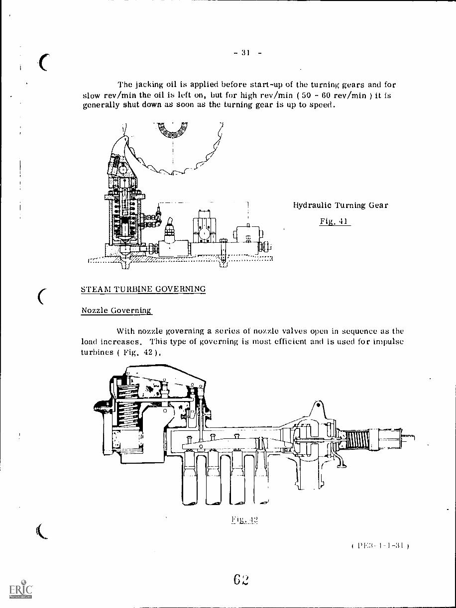
The design of a turbine rotor depends on the operating principle of theturbine,
The impulse turbine with pressure drop across the stationary blades musthave seals between stationary blades and the rotor, The smaller the sealing area,the smaller the leakage; therefore the stationary blades are mounted in diaphragmswith labyrinth seals around the shaft, This construction requires a disc rotor( Figs. 19 and 20 ),
Equalizinghole
Rotor with shrunk-on discs
Fig, 19
Solid Forged Disc Rotor
The reaction turbine has pressure drops across the moving as well asacross the stationary blades and the use of a disc rotor would create a large axialthrust across each disc. The application of a drum rotor eliminates the axialthrust caused by the discs, but not the axial thrust caused by the differential pres-sure across the moving blades.
1. Disc Rotors
All larger disc rotors are now machined out of a solid forging of nickel-steel; this should give the strongest rotor and a fully balanced rotor. It is ratherexpensive, as the weight of the final rotor is approximately 50% of the initial for-ging. ( 20 ) Older or smaller disc rotors have shaft and discs made in
1'1;3 -4-1 -if; )
41

17
separate pieces with the discs shrunk on the shaft. The bore of the discs is made0. 1% smaller in diameter than the shaft. The discs are then heated until theyeasily are slid along the shaft and located in the correct position on the shaft andshaft key. A small clearance between the discs prevents thermal stress in theshaft.
2, Drum Rotors
The first reaction turbines had solid forged drum rotors. They werestrong, generally well balanced as they were machined over the total surface.With the increasing size of turbines the solid rotors got too heavy and the hollowdrum rotor was introduced. This rotor is made of two or more pieces. For goodbalance the drum must be machined both outside and inside and the drum must beopen at one end. The second part of the rotor is the drum end cover with shaft.The end cover is made with a shrink fit and welded ( Fig. 21 ).
BLADES
H.P. STEAMINLET END
- SECTION THROUGH DRUM ROTOR-
Hollow Drum Rotor
Fig, 21
SHRINK FIT
EXHAUST ENDSHAFT AND DISC
A fairly light and rigid drum rotor may be manufactured from discswelded together to form a drum as shown in Fig. 22, Before welding, the rotoris heated by induction heating, then the welding is performed with automatic weld-ing machines for the "Argon-arc "process, where the arc burns in an argonatmosphere.
Most rotors are now made of nickel alloy-steels with elastic limits ofaround 300 x 106 pascals. Rotors for high outputs and high temperatures aregenerally made of chromium-nickel-molybdenum steels with elastic liinits of( GOO - 700 ) x 106 pascals.
( PE3-1-1-17 )

Brown-Boveri Welded Turbine Rotor
Fig. 22
Turbine Bearings
1. Journal Bearings
The bearings for small turbines are often self-aligning spherical ball orroller-bearings or they may be ring lubricated sleeve bearings with bronze orbabbitt lining ( Figs. 23 and 24 ).
Babbitt-lined Journal Bearing
Fig. 23
( 1)1Q-4-1
4;)
Ring-oiled SleeveBearing with Radial
Babbitt Facing
Fig, 24

- 19 -
2. Thrust Bearings
The main purposes of the thrust bearing are:
1. to keep the rotor in an exact position in the casing.
2. to absorb any axial thrust on the rotor.
From the thrust bearing the shaft must be free to expand in either direc-tion, thus a shaft can have only one thrust bearing. The thrust bearing should belocated at the steam inlet, where the b: le clearances are most critical. Whenshafts of a tandem compound turbine are joined together with solid couplings, onlyone thrust bearing can be applied. If flexible couplings take up the axial expansion,each shaft must have a thrust bearing ( Fig. 25 ).
Journal Bearing with Kingsbury Thrust Bearing
Fig. 25
The axial thrust is very small for impulse turbines as the pressure isequal across the rotor discs ensured by equalizing holes in the discs. A simplethrust bearing such as a ball bearing for small turbines and radial babbitt facingon journal bearings for larger turbines is very common ( Fig. 24 ).
The pressure drop across the moving blades of reaction turbines createsa heavy axial thrust in the direction of steam flow through the turbine and a thrustbearing suitable for heavy axial loading is needed. The tilting pad Kingsbury orMichel thrust bearings operating on the same principle as the tilting pad journalbearing are generally applied. The axial thrust in impulse turbines does notrequire tilting pad thrust hearings, but due to their excellent performance they
rr
5 0
( 1'1%3-4-1-19)

-
are the most common thrust bearing for large impulse turbines. The axial thrustin reaction turbines can be nearly eliminated by the use of balance or dummypistons. With the correct size of a dummy piston exposed to two different bleedpoint pressures, the thrust is nearly equalized. There is a small leakage acrossthe labyrinth seal of the dummy piston as steam leaks from the high to the lowerbleed point ( Fig. 27 ) .
The axial position of the rotor is very important and an axial positionindicator is often applied to the thrust bearing. It may be a large dial micrometerwith alarm setting for an axial movement of 0.4 millimetre and shutdown at 0.8millimetre. An oil pressure gage connected to an oil leak-off device may also beused as an axial position indicator ( Fig.26 ).
THRUST PAD
OIL FILMPRESSURE GAUGE
OIL LEAOFF
11:
STATIONARY NETTLE
THRUST COLLAR
AX /AL THRUST
1'E3-4-1-20 )
Thrust Collar Position Indicator
Fig, 26
5 LE
5W kpaoil supply
ORIFICE

- 21 -
LABYRINTHPACKING
TO PRE VENTSTEAM LEAKAGE
SteamInlet
Dummy Piston and Balance Pipe
Fig, 27
I,E3 --I -1 --2

122
With the position indicator shown in Fig. 26, the oil is supplied at say500 kPa, flows through an orifice and leaks off through a nozzle. The pressure be-tween orifice and nozzle depends on the distance between the nozzle and shaft thrustcollar; the larger the distance the lower the pressure. The pressure gage can becalibrated in millimetre clearance and may have alarm and shutdown settings.
Turbine Seals
1. Blade Seals
The efficiency of reaction turbines depends to a large extent on the bladeseals; radial as well as axial seals are often part of the shroud with the seal clear-ances kept as small as possible. As protection for the axial seals some manu-facturers apply an adjustable thrust bearing ( Fig. 28 ). The whole thrust block iscylindrical and fits like a piston in the cylinder with the whole thrust block able tobeaxially adjusted as shown in Fig. 28. During startup the thrust block is pushedagainst a stop in the direction of exhaust for maximum seal clearances. When theturbine is heated up and has been on load for a short time the thrust block is pulledforward against a forward stop for minimum seal clearance and maximum bladeefficiency.
PE3-4-1-22 )
fnd View Pert Section through X-X
Thrust Adjusting Gear for Reaction Turbine
Fig. 28
53

93
2. Shaft Seals
Shaft seals must be provided in order to prevent or at least reduce steamleakage where the shafts extend through the casings. Also when low pressure tur-bines are under vacuum the seals must prevent air from leaking into the casing.
Ordinary soft packing may be used for shaft sealing in small turbines.Carbon rings ( Fig. 29 are also very common for small turbines. The carbonring is made up of three segments butting together tightly under the pressure of agarter spring. The ring has a few hundreds of a millimetre clearance around theshaft and is prevented from turning by alocking pin. The ring has a slight sideclearance in the housing allowing it tomove freely in radial directions. Carbonrings are self-lubricating but have atendency to corrode the shaft when theturbine is shut down. The presence ofmoisture accelerates the corrosion.The carbon rings are from 10 to 25 milli-metres wide and may cause heating whenthey ride on the shaft. They are, for thatreason, limited to shafts less than 150millimetres in diameter. For largerdiameter shafts where the surface speedis high, labyrinth seals are applied. Thelabyrinth seal consists of a number of rings1 - 2 millimetres thick fixed to the shaft,tapered at the outer periphery to nearlyknife-sharp with a clearance to the casingof a few hundreds of a millimetre. Therings are of brass or stainless steel, thesharp edge gives better sealing and rubsoff easily without excessive heating incase of a slightly eccentric shaft. Somekt ;yrinth seals are very simple, othersare complicated. ( Figs. 30, 31 and 33 )
54
(a)
Carbon Ring Seal
Fig. 29
1,V3 1- 1-23 )

A(' '4 ;,4
f140If
II
//
I

;.)
High pressure turbines operating at 12 000 to 15 000 kl'a cause a sealingproblem, as a straight labyrinth seal for that pressure would be extremely longor have lots of steam leaking through. The problem is solved by a series ofsteam pockets between sets of labyrinth seals. The high pressure steam leaksthrough 100 - 200 millimetres of labyrinth seal into the first pocket, which is con-nected to the ILI; exhaust, thus any steam leaking through the seal is used in theI. P. Turbine. After the first pocket the steam leaks through the second seal 75 -150 millimetres long and into the second pocket connected to an H. P. feedwaterheater. Then steam leaks through the third labyrinth seal to the third pocket con-nected to the I. P. exhaust. The steam then leaks through the fourth seal into thefourth pocket, which is connected to the L. P. shaft seals supplying them with seal-ing steam. On the steam line between pocket number 4 and the L. P. seals aretwo connections with pressure control valves. One is a spill-over valve to thecondenser, which will open to the condenser if the gland steam exceeds the setpoint of a few centimetres of water above atmospheric pressure. The other con-nection has a control valve to supply gland steam when the pressure decreases tonear atmospheric pressure. This valve operates during start-ups and low loads.
Neither the carbon nor the labyrinth shaft seals prevent all leakage. Ifa positive or leak-proof seal is needed, a water seal may be installed, The waterseal consists of an impeller on the turbine shaft which rotates in a waterfilledcasing and water thrown out from the impeller forms a leak-proof water harrier( Fig. 32 ). Water seals are mainly applied to L.P. glands to guard against airleakage, but they may also be applied as the final seal for H. P, and LP. glands.
The water seal cannot operate properly at low speed and gland steammust be applied for sealing during start-up until the turbine speed is approximately ,-2000 rev/min. Water seals are supplied with clean cool condensate from theextraction pump. It may he supplied directly or via a head tank with automaticlevel control,
The dtaphragm,s of impulse turbines have labyrinth seals at the shaft.These seals are made of brass of stainless steel and are in six segments, eachsegment is springjoaded and kept against a stop allowing a very small clearancebetween seal and shaft, In case of a bent shaft, the shaft may push the segmentback against the spring pressure, preventing serious damage to shaft or seal( Fig. 33 )

- 26 -
Turbine Couplings
The purpose of couplings is to transmit power from the prime mover tothe driven piece of machinery. For heavy loads the solid flange coupling is used( Fig. 34 ). The flanges are generally integral parts of the shafts, but they maybe separate parts for smaller turbines. In this case each coupling part has atapered bore and keyway to fit the tapered end of the shaft. Following the taperthe shaft has a large thread allowing the coupling to be secured tightly with a largenut.
The friction between the coupling halves and the shear force of the boltstransmits the power. For maximum shear stress the bolts must be fitted ( i.e.they must fit in the holes without clearance at the shear point as shown in Fig. 34.The coupling bolts should be undercut, that is machined off to a diameter slightlyless than the bottom diameter of the thread to avoid any strain on the thread.
In some cases the couplings must compensate for axial expansion andcontraction of the rotors and in this case a flexible coupling is applied ( Fig. 35 ).The outer half has internal gears, while the inner part has matching externalgears. The coupling works like the spline on a driveshaft for a car.
The couplings for very large shafts will need a large diameter if thebolts are used to transmit the power. The bolts can be much smaller if they arenot allowed to transmit power. In the coupling in Fig. 36 shear pins carry theload. The area exposed to shear is the shear pin diameter x length x number ofshear pins. This design allows the shear pins to be located at a large radiusfrom the shaft centre. The coupling bolts are not fitted as they are exposed totensile stress only.
'Turbine Blades
The efficiency of the turbine depends more than anything else on thedesign of the turbine blades. The impulse blades must be designed to convert thekinetic energy of the steam into mechanical energy. The same goes for the re-action blades which furthermore must convert heat energy to kinetic energy. Thelater years' increase in blade efficiency is due to increased aerodynamic shapecalculated by computers and the milling of blades on automatic milling machines.
Pf.3 I- I-21;
57

27
DOWEL PINLOCKING SCREW
FITTED COLPLING BOLT
Solid Flange Coupling with Fitted Bolts
Fig. 34
pkig
won,1 1MIL
"14i
Shear Pin Coupling
Flexible Gear Coupling
Fig.35
50

- 28 -
It is not always possible to give the blades the theoretically best profile,as several other considerations must he taken. The blade must be made strongenough to withstand high temperatures and stresses from heavy, often pulsatingsteam loads. There is a iso the stress due to centrifugal force ( for large L. P.blades the centrifugal force on a single blade may exceed 200 tonnes ). Vibrationsand resonant vibrations in particular must be taken into account and finally thereis erosion and corrosion,
The material that comes closest to the ideal for all mentioned consider-ations is a chromium-nickel steel, for instance 17 Cr'13 Ni - steel.
Stationary Blades and Nozzles
The first set of nozzles for an impulse turbine is the control set and isdivided into three to six sections with each section having a steam control valve.For smaller turbines all sections may be located in the upper half of the casing,while the sections for larger turbines cover the entire circumference. All stagesfollowing the control stage have the nozzles located in diaphragms ( Fig. 37 ). Thediaphragms are in halves and fitted into grooves in the casing. Locking pieces
in the upper part of the casing prevent the diaphragm from turning. All modern
diaphragms are of an all-welded construction.\\\\, //./a
Disc-type Rotor
Fig. 37
PE3-1-1-28
5;)

29
The stationary blades in reaction turbines are fitted into grooves in thecasing halves; keys as shown ( Fig. 38 and Fig. 39) lock the blades in place, Insome cases the blades have keys or serrations onone side of the root and a calk-ing strip on the other side of the root is used to tighten the blades solidly in thegrooves. The blades are often supplied with a shroud band with radial and/oraxial sealing strips to minimize leakage losses.
The stationary blades for a Curtis wheel are attached to the casings asare the stationary blades for reaction turbines.
C
Drum-type rotor with tip-sealed bladesFig. 38
MU;q,w,.:.*.,\.,\\ .,,;\,,\-, \\MN
' \'''\ \,,\\ N \
..
Drum-type rotor with shrouded blades
Fig. 39

Barring Gears
When a turbine is left cold and at standstill the weight of the rotor will
tend to bend the rotor slightly. If left at standstill while the turbine it still hot,
the lower half of the rotor will cool off faster than the upper half and the rotor will
bend upwards " hog ". In both cases the turbine would be difficult if not impossible
to start up. To overcome the problem the manufacturer supplies the larger tur-
bines with a turning or barring gear consisting of an electric motor which through
several sets of reducing gears turns the turbine shaft at low speed. The first
turning gears turned the shaft at approximately 20 rev/min later increased to 40 and
up to GO rev/min as proper lubrication is difficult to obtain at low speed; the same
goes for the hydrogen seals of generators. Some turning gears, electric or
hydraulic, turn the shaft 1800 at set times over a period of 24 hours.
Before a cold turbine is started up it should be on the barring gear for
approximately three hours. When a turbine is shut down it should be barring for
the next 24 hours. If a hydrogen cooled generator is involved the turbine should
be kept on barring gear to prevent excessive loss of hydrogen. All barring gears
are interlocked with a lubricating oil pressure switch and an engagement limit
switch operated by the engagement handle Fig. 40 and Fig. 41 ) .
Electric Turning Gear
Fig,
Large turbines with heavy rotors arc generally equipped with a jacking
oil pump, supplying the lower part of the bearings with Oil at approximately
I() 000 k Pa , thereby lilting the shaft and supplying lubricating oil.
( I -.1 -1 -30 )
- :31 -
The jacking oil is applied before start-up of the turning gears and forslow rev/min the oil is left on, but for high rev/min ( 50 - 60 rev/min ) it isgenerally shut down as soon as the turning gear is up to speed.
STEAM TURBINE GOVERNING
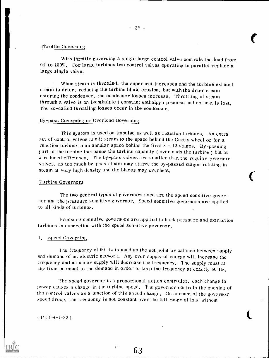
Nozzle Governing
Hydraulic Turning Gear
Fig. 41
With nozzle governing a series of nozzle valves open in sequence as theload increases. This type of governing is most efficient and is used for impulseturbines ( Fig. 42 ).
PE3- 1 1-31 )
6')
- 32 -
Throttle Governing
With throttle governing a single large control valve controls the load from0% to 100%. For large turbines two control valves operating in parallel replace alarge single valve.
When steam is throttled, the superheat increases and the turbine exhauststeam is drier, reducing the turbine blade erosion, but with the drier steamentering the condenser, the condenser losses increase. Throttling of steamthrough a valve is an isenthalpic ( constant enthalpy ) process and no heat is lost.The so-called throttling losses occur in the condenser.
lay -pass Govein or Overload Governing
This system is used on impulse as well as reaction turbines. An extraset of control valves admit steam to the space behind the Curtis wheel or for areaction turbine to an annular space behind the first 8 12 stages. By-passingpart of the turbine increases the turbine capacity ( overloads the turbine ) but ata reduced efficiency. The by-pass valves are smaller than the regular governorvalves, as too much by-pass steam may starve the by-passed stages rotating insteam at very high density and the blades may overheat.
Turbine Governors
The two general types of governors used are the speed sensitive gover-nor and the pressure sensitive governor. Speed sensitive governors are appliedto all kinds of turbines.
Pressure' sensitive governors are applied to back pressure and extractionturbines in connection with.the speed sensitive governor.
Speed Governing
The frequency of 60 Ilz is used as the set point or balance between supplyand demand of an electric network. Any over supply of energy will increase thefrequency and an under supply will decrease the frequency. The supply must atan time be equal to the demand in order to keep the frequency at exactly 60 Hz.
The speed governor is a proportional-action controller, each change inpower causes a change in the turbine speed. The governor controls the opening ofthe control valves as a function of this speed change. On account of the governorspeed droop, the frequency is not constant over the full range of load without
63
C

- 34
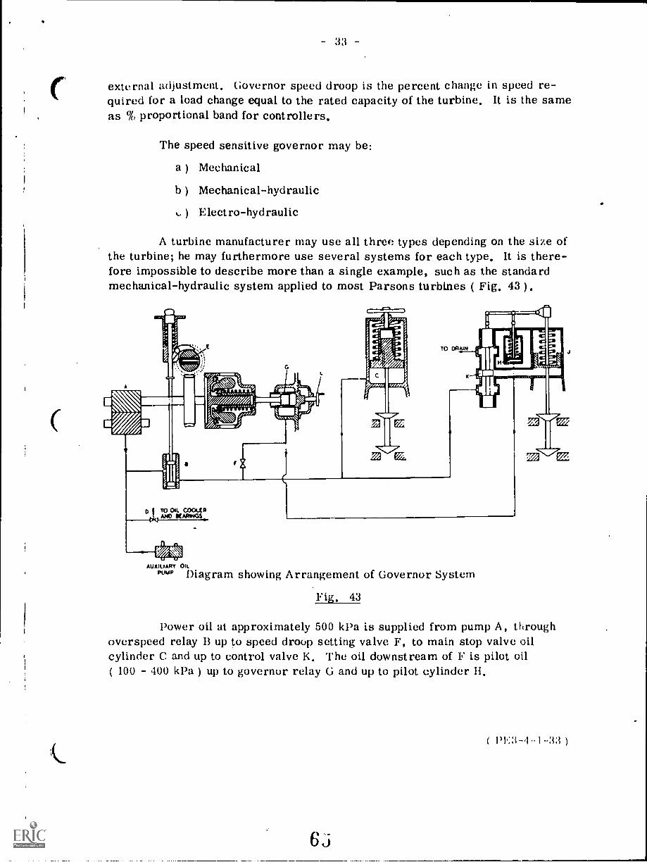
The flyballs operate the piston in the governor relay, and thereby controlsthe leak-off at the right end of the piston.
Assuming the turbine speed increases, the flyballs move outwards andmove the relay piston to the right, increasing the leak-off and lowering the pilotoil pressure causing the piston in pilot cylinder H to move downwards. As thepiston in cylinder J is stationary, the pilot piston in H will via the linkage movecontrol piston K downwards, opening the oil drain for cylinder J and the piston inJ moves downwards, but in doing so the control piston K will be moved upwardsas the piston in H is stationary. When K comes back to the neutral position, oilcan no longer drain out from J and the governor valve has taken up the positioncorresponding to the pilot oil pressure.
Turning the handwheel L clockwise will move the relay bushing to theright, decrease the leak-off, increase the pilot oil pressure for further openingof the governor valve and increasing the load. Turning. L counterclockwise willreduce the turbine load.
For smaller turbines the pilot oil may be applied directly to cylinder Jand K and 11 are omitted. The valve F is locked in a set position, but if F isopened up more, the increased oil-flow in the pilot oil system makes the systemless sensitive, i.e., the speed droop is increased; closing in on F decreases thespeed droop.
It has been pointed out that nozzle governing is more efficient thanthrottle governing and that is one of the reasons for using a velocity compoundedimpulse wheel as control stage for an impulse reaction turbine. The secondreason is that at high pressure the leakage losses around the reaction blades isexcessive. Somewhere in one of the boiler lectures it was pointed out how a fewextra kJ per kg steam could
thatthe pressure. When we expand the steam
through the turbine we find that at the high pressure a few kJ per kg steam requirea large pressure drop. For instance an adiabatic expansion of steam at 12 000 1,Paand 500° C to 7000 kPa releases 170 kJ/kg, but the same type of expansion from40 kPa to 10 kPa also releases 170 kJ/kg, and that is the second reason for thecombination of Curtis-Parsons.
Overspeed Trip
The high rotational speed of steam turbines creates large centrifugalforces, as these forces increase with the square of the speed. Therefore anabsolute reliable overspeed protection must be provided.
PE3-4-1-34
64
33
external adjustment. Governor speed droop is the percent change in speed re-quired for a load change equal to the rated capacity of the turbine. It is the sameas % proportional band for controllers,
The speed sensitive governor may be:
a ) Mechanical
b) Mechanical-hydraulic
Electro-hydraulic
A turbine manufacturer may use all three types depending on the size ofthe turbine; he may furthermore use several systems for each type. It is there-fore impossible to describe more than a single example, such as the standardmechanical-hydraulic system applied to most Parsons turbines ( Fig. 43 ).
011Sm;
11141,
.;;;1
AUXILIARY on.
PttIAP Diagram showing Arrangement of Governor System
Fig. 43
Power oil at approximately 500 kPa is supplied from pump A, throughoverspeed relay B up to speed droop setting valve F, to main stop valve oilcylinder C and up to control valve K. The oil downstream of F is pilot oil( 100 400 kPa ) up to governor relay G and up to pilot cylinder IL

- 35
The overspeed trip in Fig. 44 is mechanical-hydraulic and shows clearlythe operating principle of all overspeed trips for turbines with hydraulic governorsystems. The springloaded tripping bolt located in the turbine shaft has the centreof gravity slightly off the centre of the shaft in direction of the bolt head. The nutat the end of the bolt provides a stop for the bolt in tripped position and for thetripping speed adjustment. During normal operation the main spring holds therelay rod against the tripping lever; piston A has closed the oil drain and 11.13,oil passes between pistons A and B to the stop valve.
HAND TRIP LEVER
SWING
UPRIGHTTO TRIP
RESETTINGAr...'''. LEVER
11
IMPACT TRIP RODSPRING PISTON VALVE
OIL TO STOP VALVETRIP CYLINDER
Are Ar ff144. 1OIL DRAIN
N:::SRN di II PPAESEfEl
v/ I I I 4MAIN 'oSPRING H P OIL SUPPLY
ammo./ AIA
TRIPPING LEVER
SPRING LOADED TRIPPING BOLT
Fig. 44 TURBINE SHAFT
TRIPPED
NORMAL BOLT PATH
When turbine speed increases to the trip setting, usually 110% of opera-ting speed, the centrifugal force overcomes the bolt spring, the bolt moves to thetripping position, strikes the tripping lever, unlatching the relay rod and the mainspring moves the relay to the tripped position in which piston A opens the stopvalve oil-port to drain, while piston B closes off the II. P. oil inlet port.
For all hydraulic systems the overspeed trip closes off for H. P. oiland opens the stop valve oil cylinder to drain allowing the valve to close underspring force.
( 1'1:3- 4 -1 -35 )
66

- QUESTION SHEET -
POWER ENGINEERING,Third ClassSection 4, Lect, 1
I. Make a blade sketch and the steam pressure and velocity graphsfor an impulse turbine with one Curtis and two Rateau stages.
2. Explain the following terms and list their advantages anddisadvantages:
a) Nozzle governing
b) Throttle governing
c) By-pass governing
3, a ) Explain the working principle of a Kingsbury thrust bearing.
b) Explain the op,,i ing principle of an oil pressure thrustbearing positi ridicator.
4. The formula for centrifugal force is nt x V-
r
where in = mass in kg, V = velocity in metre/sof the centre of gravity of blade
r radius to centre of gravity of blade
Using above formula find the centrifugal force in kilonewtons of a turbine blade having a mass of 4.° '-g and rotating at 3600 rev/min whet
r = 1.5 metres.
5. Sketch and describe an overspeed tripping device.
6, Compare a back-pressure turbine and an extraction-condensingturbine and list their advantages and disadvantages.
7. What is the purpose of a dummy piston and what factors enterinto its design?
8, Sketch a solid flange coupling and explain where it would be used.
6r
P 3-4-1-(1 )

irm.-Rumonat. rianninc )11)Wi
8.2
STEAM TURBINES -- COMPONENTS
Goal:
The apprentice will be able todescribe the major componentsof a steam turbine.
1
ss
Performance Indicators:
1. Describe casings, rotors,blading and casing drains.
2. Describe packing glands,
go.ernors and extractionvalves.
3. Describe speed reduction
gears, flexible couplings,and turning gears.
4. Describe lubricating systems,thrust bearings, ring-oiledbearings and pressure-fed
bearings.
1011M,
INS I MA; 1 IUNALIkAHNIIILLis
'Study GuideIMY
Read the goal and performance indicators to find what is to be learned from
package.
Read the vocabulary list to find new words that will be used in package.
Read the introduction and information sheets.
Complete the job sheet.
Complete self-assessment.
Complete post-assessment.
2
6
'IN, I 1)%50,l,,I:ILSACIJMir 1.16012.1111.1.9.;%a ;,IP I 6.110100
°Vocabulary
* Balance pipe* Blading* Carbon ring seal* Casings* Diaphragm* Direct connected governor
* Disc rotor* Dummy piston* Emergency trip* End tightening* Extraction turbine* Flexible couplings* Flyweight governor* Grid type extraction valve
* Hollow drum rotor* Hydraulic governor* Impulse blading* Indirect connected governor* Labyrinth seal* Lubricating systems* Main governor* Mechanical governor* Cil circulating system* Overspeed governor* Packing gland* Pressure fed bearings* Pressure governor* Reaction blading* Ring-oiled bearings* Shroud* Solid drum rotor* Solid forged rotor* Speed governor* Speed reduction gears* Tang* Thrust bearings* Turning gears* Water seal* Welded rotor
3

W1 I PIM/ LIVINIAL.LtAtINIIALO I I Clv10
Introduction
A turbine consists of many components and systems for converting steam into
mechanical energy. An apprentice must understand how these components function
and interact with each other to produce power.
This package provides an explanation of the basic components and systems. With a
basic understanding of the turbine, the apprentice will have the framework for
learning the technical aspects of turbine operation. The technical details of
turbines are too complex to be mastered in a learning package. A package can be
a starting point. Experience will bring technical competence with steam
turbines.
4
71
INSTRUCTIONAL LEARNING SYSTEMS
InformationCasings
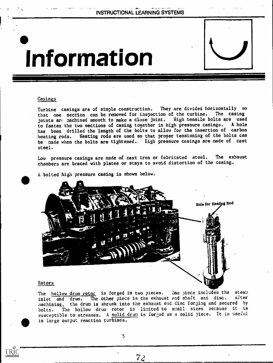
Turbine casings are of simple construction. They are divided horizontally so
that one section can be removed for inspection of the turbine. The casing
joints ar( machined smooth to make a close joint. High tensile bolts are used
to fasten the two sections of casing together in high pressure casings. A hole
has been drilled the length of the bolts to allow for the insertion of carbon
heating rods. Heating rods are used so that proper tensioning of the bolts can
be made when the bolts are tightened. High pressure casings are made of cast
steel.
Low pressure casings are made of cast iron or fabricated steel. The exhaust
chambers are braced with plates or stays to avoid distortion of the casing.
A bolted high pressure casing is shown below.
Role for Heetip6 Rod
Rotors
The hollow drum rotor is forged in two pieces. One piece includes the steam
inlet and drum. The other piece is the exhaust end shaft and disc. Alter
inachining, the drum is shrunk into the exhaust end disc fording and secured by
bolts. The hollow drum rotor is limited to small sizes because it is
susceptible to stresses. A solid drum is for3ed as a solid piece. It is useful
in large output reaction turbines.
5

INSTRUCTIONAL-LEARNING-SYSTEMS
°Informationa=1111111111111=110-MIC
Disc rotors are made up of discs or wheels which have been forged separately andkeyed to a central shaft. The outer rims of the discs are grooved for blades tobe attached. A disc type rotor for a low pressure cylinder is shown in thepicture below.
WHEELS LADES
:SHAFT
Solid forPed.rotors have wheels and shafts machined from one piece of metal.Their' single piece construction avoids problems of loose wheels. Machinedgrooves allow blading of the wheels.
Grooves for Blade Fixing
Welded Rotors
Welded rotors are made by welding metal discs onto two shaft ends. The discsare then welded together and blading grooves are machined into the outersurfaces. A welded disc is shown on the next page.
6

INSTRUCTIONAL LEARNING SYSTEMS
Information
.\AriN41)\\\\.\\\.\.
Dummy Pistons
Dummy pistons are machined out of the rotor forging at the steam ini.et,end. The
purpose of adumy :Aston is to balbance out the force caused by pressure drop assteam passes across each set of blades. A balance pipe helps to maintain the
balance of forces obtained by a dummy piston.'
Blading
Reaction blading gives a pressure drop across both fixed and moving blades.
Fixed blades are fittedin grooves in the casing. Moving blades are fitted intogrooves in the rotor. The blades are made complete with shrouding so that
installation is easier. The blades are serrated and fit into serrated grooves.They are locked in place by side locking strips. Sealing between the fixed andmoving blades is critical for efficient operation. ad tightening. is a type of
sealing provided by controlling the clearance along the lime of shaft.
Impulse blading uses blades that are machined from a solid bar. t tau isleftat the outer end for attachment of a shroud. The shroud helps to guide steamthrough the moving blades. The fixed blades of an impulse turbine has nozzlesmounted in diaphragms. Diaphragms have two fixed halves attached to the casing.Nozzles are attached in grooves of the diaphragm. The various blade types are
shown on the next page.
7
7 4
INIMM1111
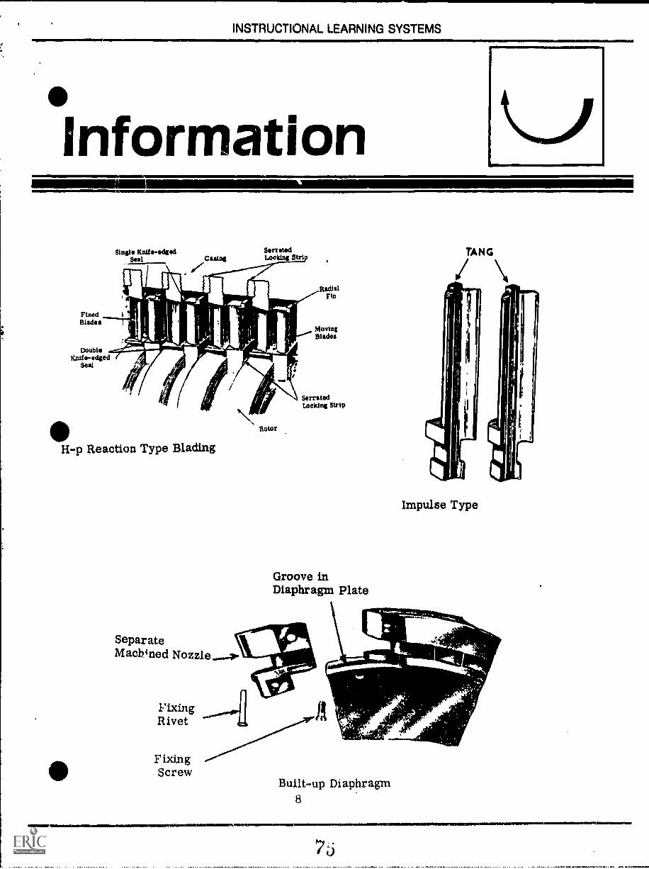
INSTRUCTIONAL LEARNING SYSTEMS
information',SWIMMER
FixedBlades
DoubleKnife-edged
Seal
Single Knife -edgedSeal Cuing
SerratedLooking Strip
H-p Reaction Type Blading
SeparateMachined Nozzle...4o
Rotor
RadialFin
MovingBlades
SerratedLocking Strip
Groove inDiaphragm Plate
FixingRivet
FixingScrew
A
Impulse Type
41.114.
--,,711r
Built-up Diaphragm8

INSTRUCTIONAL LEARNING SYSTEMS
°Information
I
LiCylinder Casing Drains
Water tends to collect at the exhaust end of a turbine. Draining grooves areformed in the casing to allow this water to drain to the condenser. Casingdrains keep the water within allowable levels.
Packing Glands
Turbines tend to leak around the shaft where it emerges from the casing. Airmust be sealed out and steam sealed inside the casing. Small turbines usecarbon rings that areheld in place by a wire spring. The labyrinth seal is usedby larger units. The labyrinth seal consists of a series of rings with sharpprojections that extend into grooves on the shaft. The projections are in closetolerance contact with the shaft and prevent steam from passing through them.Some large turbines use a water seal to prevent leakage at the shaft. A ring ofwater under pressure is maintained on the outer rim of a runner which rotateswith the shaft. This seals the gland against leakage. A combination of carbonring, labyrinth and water seals can be used to reduce leakage at the shaftgland.
Governors
Governors control the amount of steam that enters the turbine. Governing isusually controlled 4 two governors. One is to shut off the steam supply. Thisis called an overspeed or emergency trip governor. The second one maintains theturbine at a constant speed and is called the main governer. Thefly weight governor uses weights on the spindle that revolve with the spindle.Centrifugal force moves the weights outward as the speed is increased. Amechanical linkage connects the governor weights with a valve. When the
centrifugal force becomes great enough, the steam valve will be closed. This isa ilecnEdcalgmer:an-. If the flyweight governor is linked with a hydraulicsystem, it is called a hydraulic governor. A hydraulic unit is activated by thecentrifugal force. The hydraulic system will release oil under pressure tooperate a spring-loaded piston. The piston then operates the steam valve.
On large turbines, a valve is used to control steam for each set of nozzles.These valves can be operated by bar lift mechanisms, corns or levers or by
individual hydraulic cylinders.
A mechanical overspeed governor is shown in the following drawing:

INSTRUCTIONAL LEARNING SYSTEMS
Information
A hydraulic overspeed governor is shown in the following drawin3:
EMERGENCY OVERSPEEO GOVEINOR
Of
TURBINESHAFT
EMERGENCYTRIP
HAND TRIPBUTTON
THROTTLEVALVE ----al
VALVE
Nr_sCASS°°)
THROTTLE TRIP
OIL TANK
10
77

INSTRUCTIONAL LEARNING SYSTEMS
Information=1M.
A governor may be direct connected to the steam control valves through a linkagemechanism. In the application where the governor is linked with a hydraulicunit which trips the steam valves, the unit is an indirect connected Governor.All governors consist of three parts:
1. Governor speed sensitive element which is usually flyweight.2. Linkage which transmits action of the governor to steam control valves.3. Steam control valves.
Extraction Turbines
Extraction turbines requires a governor that will control the flow of steam
beyond the extraction point. Steam must be extracted and yet leave a flow thatsatisfies steam requirements beyond that point. A ;;rid type extraction valve
is made up of a disc that revolves on a grid. Each have ports for steam to pass
through. If the ports coincide, a full flow of steam passes through. Partially
matched ports allow only a portion of the steam to move by the extraction point.This allows steam to be extracted and still maintain pressure to other parts of
the turbine. A arid type extraction valve is shbwn in this drawing.
TO PRESSURE GOVERNOR
OPERATING PISTON
VALVE.GRIDV LVE
DRAIN
OIL ORSTEN.,INLET
The pilot valve is operated by the pressure ooverAor to control the ste2.:1 to thepiston. The piston action rotates the extraction grid. A soeed governor is
linked with the pressure governor so that the turbine speed is not chunked by
!,team extraction.
11
71Q

INSTRUCTIONAL LEARNING SYSTEMS
InformationSpeed Reduction Gears
Often the speed of the turbine is too great for the speed of the machine to be
driven. Speed reduction gears are used to slow the speed of the turbine. The
gear sets are housed in casings and connected to the turbine and unit to be
driven by flexible couplings.
Flexible Couplings
Flexible and claw-type couplings are used to connect the turbine with generators
and other driven units.
SI_E EVE
OIL-SuPPLy GE ARNOZZLE TEETH
Turning Gears
GEARTEETH OIL SUPPLY
OIL OUTLE T1,10ZZLL
Flexible Coupling
GENERATORROTOR
COUPLING JAWS
Claw Type Coupling
TURBINE SHAFT
TURNING GEAR
Turning gears are usl i to keep the shaft turning after the turbine is shut down.
The turning gear is needed to allow the shaft to cool evenly between bearings
and avoid distortion from high operatin3 temperatures. It consists of an
electric motor and a reduction gear that remains disengaged when not in use.
The turning gear is disengaged or engaged with the turbine shaft by use of a
yoke and worm gear arrangement.
LIIIIELPJL:11111YALTE
Large turbines have oil circulating systems tnat lubricate bearings, governor
mechanisms and generator bearings. i4iedium size turbines use ring-oiled bearings
and an oil circulating system. Small turbines are orovided with ring -oiled
bearings with some hand oiling of moving ?arts.
12

INSTRUCTIONAL LEARNING SYSTEMS
InformationThrust Bearings
Thrust bearings are needed to control axial thrust and maintain position of the
moving parts in relation to the stationary parts of the rotor.
The ring-oiled bearing rides free on the rotating journal of the turbine. As
the journal rotates, the ring dips into an oil reservoir and carries oil up to
the shaft. Grooves in the bearings channel oil to the bearings.
Pressure-fed Bearings
The two main bearings of a turbine require a high level of oil to lubricate andcontrol friction. The oil serves as a cooling agent as well as a lubricant for
main bearings. To insure an adequate oil supply to the main bearings, a
circulating pump is used to deliver oil to the bearings.
Oil Circulating Systems
In an oil circulating system, oil is delivered at full pump pressure to the
governing mechanism. The oil is reduced in pressure and flows to another headerthat supplies the bearings and other working parts. Oil then returns to the oilreservoir for recycling through the lubrication system.
EXCITER
GENERATORSECONDARY OIL
RELAYS
TURBINESTEAM *OMISSION
VALVE
OIL SIGHT PRIMARY OILRELAY
OVERSPEEDGOVERNOR
GOVERNOR
LOW BEARING-OIL PRESSURE
TRIP
TRIP ANO-'-TmROTTLE
VALVE
WINawl,
RELIEFVALVE
OILCOOLER
13
PUMPGOvERNOR
VAPOUREx TRACTOR
OIL- SIGH TOVERFLOW
RELIEF vaLvEAUXILIARY OIL PUMP
OIL nESERvOift-
CENTRIFUGEOR FILTER
PUMP

INSTRUCTIONAL LEARNING SYSTEMS
Assignment ,Read pages 9 - 37 in supplementary reference.
Complete the job sheet.
Complete the self-assessment and check your answers with answer sheet.
Complete the post-assessment and ask the instructor to check your answers.
14
NMISIMAMIMMEI

INSTRUCTIONAL LEARNING SYSTEMS
LSPECT A STEAM TURBINE AND IDENTIFY ITS COMPONENTS
* Locate a steam turbine at your job site or other location.
* Carefully'inspect the turbine and identify its working components.
* Determine (if possible)
- How the casing is opened for inspection and location of heating holes in
casing bolts.
- Type of rotor
- Type of blading
- Location of casing drains
- Type of seals in packing glands
- Type of governoring mechanism
- Type of turbine (condensing, non-condensing, extraction)
- If the unit have a speed reduction mechanism
- How turbine is connected to generator
- If unit has turning gears
- Type of lubricating system
* Ask a journeyman to explain components that are encased in housings or not
obvious from your inspection.
15

INSTRUCTIONAL LEARNING SYSTEMS
*SelfAssessment
1111111
1. High pressure turbine casings are made of
2. rotors are formed by welding metal discs onto two shaft
ends.
3. blading of a rotor gives a pressure across both
fixed and moving blades.
4. The clearance along the line of shaft can be controlled by a type of sealing
called
1110 5. A tang is left at the end of a blade so that theattached.
6. List three types of seals used in packing glands.
7. A governor that shuts off the steam supply isGovernor.
can be
8. A governor that maintains the turbine at a constant speed is thegovernor.
9. A governor that utilizes a hydraulic unit to trip the steam control valve
is called a governor.
10.
moving parts of a turbine.
bearings are used to control axial thrust of the
16
'1
8,3

INSTRUCTIONAL LEARNING SYSTEMS
Self AssessmentAnswers
1. Cast steel
2. Welded
3. Reaction
4. End tightening
5. Shroud
6. Carbon rings, labyrinth seal, water seal
7. Overspeed or emergency trip governor
8. Main governor
9. Hydraulic
10. Thrust
17
.

INSTRUCTIONAL LEARNING SYSTEMS
PostAssessment
1. What type of lubricating system is used on large turbines?
2. What type of lubricating system is used on small turbines?
3. List two types of couplings for linking turbines with generators and otheracessories?
4. Turbine speeds can be slowed to the speed of driven machines by the useof gears.
5. List a common type of extraction valve for governing extraction turbines.
6. Which type of governor is used to maintain a constant tue:Ane speed?
7. Which type of governor is used to shut off the steam supply of a turbine?
8. What is the purpose of cylinder casing drains?
9. What is the purpose of the tang on a blade?
10. What is the purpose of a dummy piston?
18

INSTRUCTIONAL. LEARNING SYS! tMS
Instructor"Post AssessmentAnswers
1. Oil circulating system
2. Ring-oiled bearings and hand oiling of moving parts
3. Flexible and claw type couplings
4. Speed reduction gears
5. Grid type
6. Main governor
7. Overspeed or emergency trip governor
8. Drain water that collects at the exhaust end of the casing
For attachment of the shroud
10. To balance out the force caused by pressure drop across each set of blades.
19
INSTRUCTIONAL LEARNING SYSTEMS
SupplementaryReferences
h Correspondence Course. Lecture 4, Section 3. Second class. Southern
Alberta Institute of Technology. Calgary, Alberta, Canada.
20
8'7

SOUTHERN ALBERTA INSTITUTE 01.I*ECIIN0 LoGYCALGARY, ALBERTA
Correspondence CoursesPower Engineering
SECTION 3
PRIME MOVERS
STEAM TURBINES I
Introduction
Second ClassLecture
It is only during the last fifty years that the steam turbine has reallycome into its own in the field of prime movers. Modern industry in itsquest for super-efficiency and economy dictates that electrical power beproduced in central stations and distributed by line to industrial centresand isolated plants alike. This trend has been more than instrumentalin the recent great developments which have taken place in steam turbinedesign and application.
Principles of Operation
Horizontal steam turbines as installed in stationary plants are pro-duced in a wide range of sizes. The smaller machines, producing up toabout 225 kW and running at high speeds, are usually employed to driveexhausters, exciter sets, small lighting generators and other compara-tively low power-consuming plants. The larger turbines, some of whichare capable of outputs of up to 500 MW, and running at speeds below4 000 rev/min, are usually found in really large iAstallations such aspublic power stations a. 't the power Louses which :urnish power and lightfor large industrial eudertakings.
The revolving member of a steam turbine known as the rotor, con-sists of a shaft or sWndle upon which the blades are attached. Thein passing through these blades does useful work and so causes
the rotor to revolve. This conversion of the potential energy of thesteam into useful energy is effected in two stages.
8d
15,2

Firstly, the pressure energy is converted into kinetic energy as thestun expands through the nozzles and the pressure drops, These nozzleswhich may be either stationary or movable arc so designed that the steamexpands from a high pressure to a lower pressure and in doing so producesthe maximum velocity possible in the steam jet,
Secondly the kinetic energy of the jet is converted into useful work bychanging the directional momentum of the steam by blades or buckets. Insome designs both funetiOns take place simultaneously,
Thus it is obvious that the two most important parts in any steam turbineare the nozzles and the blades, since upon the design and efficacy of thesecomponents depends the overall efficiency of the whole machine. Fundament-
.the two processes by which the energy in the steam is converted intorotary motion can be broadly divided as follows:
(1) by the impulse type turbine,(2) by the reaction type turbine.
THE IMPULSE 'TURBINE
In the impulse type turbine the steampressure is reduced in stationary nozzleswhich also serve to increase its velocity.The high velocity steam impinges uponthe blades and imparts an impulse tothem rotating the shaft.
Figs, 1 and 2 show diagrammaticallya simple impulse turbine in which the steamis expanded completely in one step. Thisresults in a very high rotational speed.
\f
',^ e
.,".1 !.
11; A',,
Itotor and Nozzle of a Simple ImpulseTuhin Fig, I
Steam emerges from the nozzle at ;.thigh \'elocity stikes the blades\iiih change its dirition flo\v,
8
rN INNOZZLE BLADES
VELOCITY OFSTEAM LEAVING
CONDOMPRESSURE
it
LIVE STEAMLNTERING
EXHAUST
STEAMLEAVING
BLADE
ROTOR
CASING
BEARING
Simple Impulse 'FurbincFit, 2
The steam pressure is reiltii inthe stationary nozzles and the :it.,11velocity steam jet impinges upon theblades, thus imparting mot ion to in in

Lower turbine speeds can be obtained without ;in excessive loss ofefficiency by using two sets of moving blades mounted on the same disc,each absorbing its share of the energy in the steam. This principle isknown as Velocity Compounding and is illustrated diagrammatically inFig. :1.
Referring to Fig. 3, steam enters the turbine casing and, after expan-sion in the nozzle, is directed at high velocity into the first row of movingblades, where part of the velocity is absorbed. After the first row of mov-ing blades, the steam enters a row of stationary baldes which are fixed tothe turbine casing and located between the two rows of moving blades. Thestationary blades simply change the direction of the flow of the steam sothat it will enter the second row of moving blades at the correct angle. Bythe time the steam leaves the second row of blades all the availablevelocity has been absorbed.
IN ,IN MOVING BLADESZB4 1-.41
11 STATIONARY II111..ADE. I I
VELOCITY OFI ''STEAM LEAVING
CONDENSER' PRESSURE
I I
1
MOVING
BLADES -CLEARANCE
' NE STREAMI. NI DING
E XNAUTSTEAM
LEAVING
STATIONARYBLADES
SING
BEARING
Vchwity Compounded Impulse TurbineVit,;. :1

- 4
There is another system of velocity compounding in which one set ofmoving blades is used, known as the re-entry type turbine. In thissystem the steam, after passing through the blades once, is reversed anddirected back again into the same set of blades. Two types of constructionmake this possible and these are illustrated in Figs. 4 and 5.
REVERSINGCHAMBER
N NOZZLEIv
SHAF.
PATHOF
STEAMWHEEL
BL AOING
Re-entry Method of VelocityCompounding
Fig. 4Steam issuing from the nozzle at a
velocity passes through therwo of moving blades to a revers-ing chamber. In this chamber vanesre-direct the steam back through thesame row of moving impulse blades.
BLADING
NOZZLE
Another Method of Re-entryVelocity Compounding
Fig. 5The steam discharged from thenozzle enters pocket-like bucketson the rim of the wheel. Reversingguide passages placed in the sta-tionary casing opposite the bucketsare designed to re-direct the steamhack into the buckets again.
In addition to velocity compounding as a method of reducing turbinespeeds without loss of efficiency, impulse turbines may be designed toreduce the steam pressure in steps or stages. This is known as PressureCompounding or pressure staging, each set of expansion nozzles withimpulse blading being known as a pressure stage.
This principle is diagrammatically illustrated in Figs. f;, 7 and 8,and is equivalent to mounting several single-stage impulse turbines ona common shaft. In large units velocity compounding is usually employedin the first pressure stage and pressure compounding in the remainingstages.
(PF,2-3-4-4)
Ji

5
Referring to Fig. ti below, the high-pressure steam expands in thefirst set of nozzles rUid then passes through the first row of movingblades. It then expands again in another set of nozzles and passesthrough another set of moving blades.
The design shown in Fig. 7 is a combination of velocity compounding andpressure compounding. Each element of the pressure compounding or stagecontains a complete example of velocity compounding.
The portion of the turbine shownin Fig. 8 has one velocity and fourpressure s'.ages. The graph abovethe cross-section of the nozzles andblades shows how the pressure andvelocity change as the steam passesthrough the turbine. The pressuredrops as the steam expands in thenozzles but remains constant as itpasses through the moving blades.
The first stage is designed fora greater pressure drop than theremaining stages and so the veloc-ity of the steam leaving the firstnozzle is much higher.
This higher velocity can beused more advantageously to pro-duce work if it is reduced in twosteps. Hence, in this stage thereare usually two rows of movingblades and cur intermediate rowof stationary guide blades. . Thesteam velocity decreases in bothrows of moving blades and I'VIllainticonstant in the guide vanes.
The diagram is or a pureimpulse turbine, but most modernturbines are designed to incorpor-ate a greater or lesser degree.ofreaction.
IN IN
r;I 1
1
II I
liVELOCITY Of
..1.- %oat5 t5I di I 11
STEAM LEAVING
is 'aii 'CONDENSER
g= gll,1:.,... , It.. >. .
_0 1 prIEssum
ii }ii
11 41 II:
II
_LiI
I ,if :
CLEARANCE
ENE STEAMENTERING
BLADE
DIAPHRAGM
WHEEL
EXHAUST
STawLEAVING
CASING
AAING
Pressure CompoundedImpulse Turbine
Fig. (;
(1)1.,2-:i.--1

INNOZZLE IN NOZZLE,IN MOVING BLADES i 111N MOVING BLADES
.1 /1
1- -;, 1 I IN I
i''N `t .r- -ii. /-1,IN I" "I
I
i1 STATIONARY '
i' STATIO RY I Pressure Velocity
,..!I'll+.,-- II
'MI (VELOCITY OFI
11 1 sTEAm LEAVING Compoundingoff, °L; 1 II if '
Ig'i.'; I.1 Impulse Turbine
IPREisuRI !PRESSUREI :CONDENSER
Fig. 7'"jI
a- - >,- I
(.4rkr, 11 , ii ii ii ,
... ... FIST/4CE- -I --T-.---ti---4sTAde, :..1, .
CLEARANCMOVINGBLADE
LIVE STEAMENTERING
DIAPHRAGM
EXHAUST
STEAMLEAVING
STAT ION ARTBLADES
CASING
BEARING
Impulse Turbine with Velocityand Pressure Stages
Fig. 8
93
INNOZZLE STATIONARY BLADES,I 1,41
: MOVING -44"r'
$!;aL.DEs
. 4..'
PRESSURE 'PRESSUREOF LEAVINGSTEAM
LIVE 5 TEAmENTERING
VEL ITY5 TAGE PRESSURE STAGES
VELOCITY'h0f. if AVI*5
STEAM
EXHAUSTSTEAM_..LEAVING

Itl.:At"I'l()N TURBINE
In the reaction type of turbine, the expansion of the steam occurs inmoving nozzle-shaped blades which produce an increase in the velocity of thejets passing through the blades and also a change in direction, as a result ofwhich a driving force is imparted to the blades and so to the rotor.
The pure reaction type of turbine is not a practical proposition and is,therefore, never encountered. The introduction of the steam into the fastmoving blades of the rotor presented some difficulty but the problem wasovercome by projecting the steam into the moving blades by means ofstationary nozzles.
In theory, the nozzles expand the steam just sufficinetly to give it avelocity equal to that of the moving blades. The steam should then pass intothe blades without impact and upon further expansion in the nozzle-shapedblades the potential energy remaining in the steam is converted into kineticenergy.
In actual fact the velocity of the steam produced in the stationary nozzlesis greater than the velocity of the blades and the jets strike the latter andproduce an impulse effect. Then the further expansion of the steam withinthe blades produces a reactive force and the rotor is caused to rotate by thethe combined action of both the impulseand reactive forces. Turbines acting onthis impulse reaction principle are
referred to as Reaction Turbines and anillustration of the principle is shown inFig. 9. Impulse and reaction types ofblading are sometimes combined andused together in the same turbine.Fig. 10 shows such an arrangement. Thefirst high-pressure stage is of the vei-1 -ity compounded impulse type and thelow-pressure stages arc of the reactiontype.
Referring again to Fig. 9, steamunder pressure enters a row of station-ary blades which direct it into a row ofmoving blades affixed to the rotor. Afterleaving this first row of moving blades ,
the steam enters another row of station-ary blades before being passed throughother moving blades. The steam pres-sure drop across both the moving andstationary rows of blades is evidentfrom the graph.
Compound reaction turbineson:-;ist of individual high and low pres-sure units. The steam enters the high-pressure turbine and expands as it flA,,vsthrough the turbine. The low-pressurend ialce; :oeam. expands it still
Hillier :Intl l'\11:111:;1'; st I r(indentil..
lh,,IN MOVING, N...40E§-: AicIrtr-'IttlIN . 1 iiT I ON ARY IttAtilt Ill
II I ii i It : 1,1, VELOCITY OFAll ;; ;; STEAM LEAVING
sts. II I CONDENSER 1
ei II PRESSURE
I
II II ///1
.,..1II 7ELocirtil-- I 1
94
I
I I
MOVINGBLADES,
,CLEARANCE-
LIVE ST AMENTERING
EXIitUSTSTEAM
LEAVING
CASING
EARING
Simple Reaction Turbine
-1 -7)

- 8 -
(01 par
STATiONARY!I& / "44
t-L STATIONARYILAOIS
nOVINC
WOES
Reaction Turbine with VelocityCompounded Impulse Stage
Fig. 10
&TEA/1,101.ff
lE2-3-4-8)
With further reference toFig. 10, in the reaction section ofthis turbine only three rows of mov-ing and fixed blades are shown.There are, however, many morein the complete turbine. Both thestationary and moving blades formnozzles and the steam pressuredrops and velocity rises as itpasses through them. Impingingagainst the moving blades in thedirection of rotation the steam im-parts energy to them due to impulse.
The moving blades aresimilar to the stationary bladesand the steam expands as it passesthrough them. This expansion andpressure drop increases thevelocity of the steam with respectto the moving blades and, uponleaving, imparts energy to themby reaction. The graph shows thechanges in pressure and velocityrelative to the stationary bladesas steam passes through the tur-bine. Reaction blades receive moreenergy from reaction thanimpulse.
In the radial reaction orLjungstrom turbine, Fig. 11, thesteam flows outward from thecentre in a radial direction throughreaction nozzles formed by movingblades placed axially. Alternaterows of ')lades move in oppositedirections and as these are con-nected to two independent shaftsthese must also revolve in oppo-site directions. Each shaft isconnected to an individualgenerator.
Radial Reactionor lijungstrom TurbineFig. 11
- 9 -
TURBINE CONSTRUCTION
Turbine Cylinder Casings
Turbine casings are made as simple in shape as possible so as to reduceto a minimum any distortion due to temperature changes. They are dividedinto two parts on a horizontal joint so that the machine can he opened up forinspection and overhaul and the rotor removed without disturbing the alignmentof the bearings.
Both top and bottom halves of the casing have flanges with holes drilled inthem to take fixing bolts. Where there is insufficient clearance for bolts, studsare used.
The joint faces of both top and bottom casings are accurately machined tomake a good joint, the pressure on the joint being considerable in the H-pcylinders. High tensile steel bolts are used for the H-p casings, which areusually made of cast steel, and in this case, these bolts have a hole drilleddown their length to allow for the insertion of carbon rods for electrical heatingwhen tightening down. This method allows proper tensioning of the bolts to hecarried out. Fig. 12 shows a bolted casing joint and an illustration of the typeof bolt used.
In some designs of flanges, in order to relieve stresses, vertical saw cutsare made from the edge of the flange through to the bolt holes.
The L-p casing, which is made of cast iron or fabricated steel, is so shapedas to allow adequate passages for the steam as it leaves the last row of bladesto flow into the condenser without eddying. The exhaust chambers, which areconnected to the condensers, are braced with plates and stays to prevent distor-tion or collapse of the casing.
The cowlensers are placed below the 14-p casing and the mass is takenthrough springs supported from the basement-level floor. The mass of theturbo-alternator is carried by the steel and concrete foundation block.
ensure that correct alignment of the turbine is maintained under allconditions of operation, provision is made to allow free axial expansion andradial expansion. When referring to turbine steam flow, or expansion or con-traction, the term axial means along the line of the shafts, and radial (or.transverse) means at right angles to or across the line of the shafts. The Is-pcylinder easing exhaust is usually anchored to the foundation axially ohly, atone point, and movement of both the L-p and the 11-p cylinder casings is allowedto take place, by means of sliding supports or keyways, to suite the particulardesign of turbine.
An example of these sliding supports for a 11-p cylinder is shown in Pig. 13(a).It will be seen that the cylinder casing is rigidly connected to the bearing pedestaland yet is free to move radially out ;rom the shaft in all directions and still remain in alignment. The bearing pedestal is allowed to slide axially on keywaysfitted between the stool or bedplate and the pedestal. An example of an arrany,e-ment for the expansion of a two-cylinder t Sh()%vn in it, 1:Wo.
9d
( -9)

P
ak. 1.
417111r
4
Bolted fl-p Cylinder JointFig, 12
CYLINDERCASING
SLIDING KEYWAYSFOR CYLINDER
RADIAL MOVEMENT.VERTICALLY
74\Hole for Ile:twig Rod
hi* al
SLIDING KEYWAYFOR CYLI N DERHORIZONTALMOVEMENT
BEARINGeP).ESTAL
KEYWA" FOR AXIAL MOVEMENT OF BOTH
BEDPLATECYLINDER AND PEDESTAL
II Ii l'iih.stal and Casing Sumnirl

I 11011.1.14 Pair Os 011119 IU .1161(1.1INIC/Is1,
111i CO natall COVII.14.
-vero_Tr1111111111 I 1 ON
111I 10111.MG ou .4111.11 10 ICIUMM1110M1
C 1111111M111.11G at, 111111M0k
Provision for Expansion of Two-cylinder Turbine13(l))
In some turbines the pedestal bearings are fixed solid to thehumdation and the casings are alluweil to expand axially at one endby means of supportinp, feet or "paws", as they are often called, and
keyways. Radial exp:insion keywa's are used similar to thosedescribed for 1:ig. 1:10).
T111.11111C H(q1)I'-;
Turbine rotors niay ot tour main types as tolhAvs:
1. FoiT,ed Steel 1)ruin Itotor
1)1:;e Rotor
Vorged Rotor
i. kVelded Rotor
BEST COPY AVAILABLE
9 s

- 12
Drum Rotors
In the hollow drum type rotor, Fig. 14(a) the 11-p steam inlet endof the rotor and drum is a single steel forging and the exhaust end shaftand disc is another separate forging. After machining, the drum isshrunk onto the exhaust end disc forging and secured by bolts and driv-ing dowels. Grooves are machined in the body of the drum to take thenecessary blades.
The hollow drum type rotor is limited in its application because ofthe excessive stresses which would occur if it were made in large sizes.The main advantage of this construction is that there is approximatelythe same mass of metal in the rotor as in the cylinder casing. There-fore, there is the same response to changing temperature conditions inboth rotor and casing and working clearances can be kept to a minimum.
Drum rotors are used to carry the reaction type blading in the fl-pcylinders of the Parsons design of turbine. Fig. 14(a) illustrates theconstruction of the hollow drum type rotor.
The solid drum type rotor, Fig. 14(b) is suitable for cylinderswhere there are lower temperatures but 1:trge diameters. For examplethey arc used in the intermediate cylinders of large output reactionturbines.
PAL ANrLPiS t
(1)1.:2 ;-- 1 1
liAPUt. SE
" DWIM 1(.i? PI AC flOt4 al AUF
Ilollom; Drum(a)
Li
solid Drum(1
Fig. 11
BEST COPY AVAILABLE
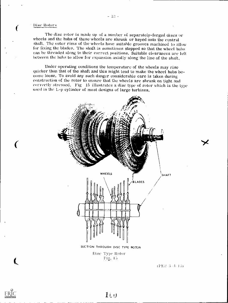
1:: -
Disc Rotors
The disc rotor is made up of a number of separately-forged discs orwheels and the hubs of these wheels arc shrunk or keyed onto the centralshaft. The outer rims of the wheels have suitable grooves machined to allowfor fixing the blades. The shaft is sometimes stepped so that the wheel hubscan he threaded along to their correct positions. Suitable clearances are leftbetween the hubs to allow for expansion axially along the line of the shaft.
Under operating conditions the temperature of the wheels may risequicker than that of the shaft and this might tend to make the wheel hubs be-come loose. To avoid any such danger considerable care is taken duringconstruction of the rotor to ensure that the wheels arc shrunk on tight andcorrectly stressed. Fig 15 illustrates a disc type of rotor which is the typeused in the L-p cylinder of most designs of large turbines.
SECTION THROUGH DISC TYPE ROTOR
Disc T15,.
1Lf)

14
Solid Forged Rotors
Rotors of this type have wheels and shaft machined from one solidforging, the whole rotor being one complete piece of metal. This resultsin a rigid construction, and troubles due to loose wheels of the shrunk-ontype are eliminated. Grooves are machined in the wheel rims to take thenecessary blading.
Solid forged rotors are used in the 11 -p and 1-p cylinders for mustdesigns employing impulse type blading and for the I-p cylinder whenreaction type blading is used. Fig. 16 shows a rotor of the solid forgedtype.
Welded Rotors
Welded rotors are built up from a number of discs and two shaft ends.These are joined together by welding at the circumferences and becausethere arc no central holes in the discs the whole structure has considerablestrength. Small holes are drilled in the discs to allow steam to enter insidethe rotor body to give uniform heating when coming on load. Grooves aremachined in the discs to carry the blades and Fig. 17 (a) and (b) show thistype of rotor construction.
Welded rotors are used in the Swiss Brown-Boveri designs of turbinesin the 1-p and L-p cylinders.
Grom.es for Blade Vixing
cA,4440,44,45.11t406606
:;-- I -I I)
solid Forged RotorFig. 16
f,

Rotor showing Discs before Welding(a)
\\\\\\\\\N
\\\ t
It»t»r ;titer Welding Discs 1»gether(b)
17
I.»

Testing of Rotors
Great care is taken during the manufacture of turbine rotors becausethey must be sound and as free from internal stresses as possible. Manytests are carred out to ensure that any flaws in the metal arc detectedbefore final dispatch of the rotor to site for erection in the turbine.
Dummy Pistons
There is a pressure drop across each row of blades in a reaction typeturbine and a considerable force is set up which acts on the rotor in thedirection of the steam flow. In order to counteract this force and reducethe load on the thrust bearings, dummy pistons arc machined out of therotor forging at the steam inlet end, It is usual to have a dummy piston foreach cylinder except for the L-p double-flow cylinders where the steam flowsin both directions and the forces are balanced out.
The dummy piston diameter is so calculated that the steam pressureacting upon it in the opposite direction to the steam flow, balances out theforce on the rotor blades in the direction of the steam flow. It is prefer-able that the dimensions be so arranged as to keep a small but definite thrusttowards the exhaust end of the turbine. To help maintain this condition at allloads a balance pipe is usually connected from the casing, on the cuter sideof the balance piston, to some tap-off point down the cylinder. Both dummypiston and balance pipe arrangement arc shown in Fig. 18.
LABYRINTHPACXING
TO PREVENTSTEAM LEAKAGE
STEAM THRUSTON BLADES..11111111.-
THRUST DUE TOSTEAM PRESSURE
(1)E2-3-1- Ili)
ali(1 li:11;111c('Flo IS
103

- 17 -
Blading
No detail in the construction of a turbine affects the reliability and efficiencymore than the design of the blading. This applies particularly to the movingblades which are attached to the turbine rotors.
Depending upon the design of the turbine there is either an impulse force(impulse type blading) or a combination of impulse and reaction forces (reactiontype blading) acting on the turbine blades due to the sieam flow. The longer theblade the greater the bending force at the root or fixin; point of the blade.
In addition there is a centrifugal force, due to the speed at which Ole bladeis rotating, trying to throw the blade outwards.
These two forces - the bending force and throwing-out force - are at maxi-mum in the largest blade wheel at the L-p exhaust ,ind of the turidine. Thus thestresses which these forces impose, limit the size of the blades and the diameterof the last wheel. This limitation is one of the reasons why turbines are designedwith double flow in the L-p cylinder.
The mechanical stresses just described are not a great problem in the small11-p moving blading but this blading is subject to much higher temperatures andbecomes the greater problem from the designed aspect.
The fixed blades are secured to the turbine cylinder casings and in theimpulse type of blading take the form of nozzles set in diaphragms alternatelybetween each row of moving blades.
Reaction Type Blading
In reaction type blading a pressure drop occurs across both the fixed andmoving blades. In the 11-p cylinder a very effective seal between fixed andmoving blading is essential to prevent steam leakage vhich would make theturbine inefficient.
The fixed blades are fitted in grooves in the cylinder casing and the movingblades in grooves machined in the rotor.
For blading subject to high temperature in 11-p cylinders, the blades aremade complete with root section and shrouding in one piece and are formed ingroups or packets for convenience of handling. The shrouds have a projectingportion which is thinned down to form a single knife edge on the moving blades.On the fixed blades a second strip is added which is tapered to form a doubleknife edge. The blade packets are then fitted in the grooves to form a completerow of either fixed or moving blades. The blade packets are serrated alongthe roots and secured in the grooves which are also serrated, by means of side-locking strips.
(1'E2-3-1-17)
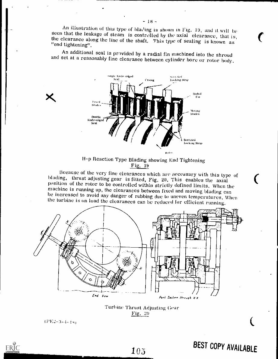
- 18An illustration of this type of blak'ing is shown in Fig. 19, and it will beseen that the leakage of steam is controlled by the axial clearance, that is,the clearance along the line of the shaft. This type of sealing is known as"end tightening".An additional seal is prwided by a radial fin machined into the shroudand set at a reasonably fine clearance between cylinder bore or rotor body.
rIgh. Knife-edgedSeal Asti*
I.111.41
IAA king :Am.
Doubleundo -edged
Seal
11-p Reaction Type Blading showing End TighteningFig. 19
Because of the very fine clearances which are necessary with this type ofWading, thrust adjusting gear is fitted, Fig, 20. This enables the axialposition of the rotor to be controlled within strictly defined limits. When themachine is running up, the clearances between fixed and moving Wading canhe increased to avoid any danger of rubbing due to uneven temperatures. Whenthe turbine is on load the clearances can be reduced for efficient running.
(1'l..1-3-.1- 1 s)
Port Sect, en th,ougA X-X
Turbine Thrust Adjusting GearFig. 20
10511111111111111Nommnimidmomm-------,..
BEST COPY AVAILABLE

Impulse Type Bladiny,
The H-p moving blades for impulse type turbines are machined fromsolid bar and the roots and spacers formed with the blade. This is illus-trated in Fig. 21. Such construction avoids the use of distance pieces orpackers when assembling the blades in the wheels. Tangs are left at the tipsof the blades so that when fitted in position in the wheel the shrouding can beattached. The shrouding is made up from sections of metal strip punched withholes to correspond with the tangs. The strip is passed over. the tangs whichare then splayed out to secure the strip in position. The shrouding is fittedin separate sections to allow for expansion.
There is no pressure drop across the moving blades of an impulse typeturbine and therefore the sealing arrangements are not of such greatimportance as in the reaction type. The shrouding on the impulse bladinghelps to guide the steam through the moving blades, allowing larger radialclearance, as well as strengthening the assembly.
The fixed blading in an impulse turbine takes the form of nozzles mountedin diaphragms. The diaphragm is made in two halves, one half being fixed tothe upper half of the cylinder casing and the other half diaphragm to the lowerhalf cylinder casing. The diaphragms are located in the cylinder casings bymeans of keys so that when expansion occurs, fouling of the shaft seals isavoided. Special carrier rings are generally used to support the diaphragmsin 11-p cylinders.
Stages in the manufacture of 11-p Impulse TypeMoving Blades
Fig. 21
( 1' 1..2- 19)
C

20
At the 11-p end of the turbine the diaphragms are of the built-up type.Each nozzle is machined separately from a solid bar and attached by groovesand rivets to the diaphragm plate. In some cases the nozzles are also weldedtogether and to the plate. Fig. 22 shows the manner in which the nozzles arebuilt up around the diaphragm plate.
Due to the steam pressure difference on each side of the diaphragm it isnecessary to provide seals at the hole, where the shaft passes through thediaphragm, to prevent steam leakage along the shaft.
SeparateMachined Nozzle,-,-
Groove inDiaphragm Plate
FixingRivet
FixingScrew
Pl
A
;le
Built-up Diaphragmig. 22

- 21 -
Cylinder lasing Drains
Increased steam pressure and the higher efficiencies of modern turbineshave increased the percentage of wetness at the exhaust end; 14% is generallytaken as the maximum allowable. The shape of the cylinder c ,ing allows thiswater to drain to the condenser but special draining grooves ar arranged inthe cylinder casing to help remove this water more effectively.
An example of this type of draining arrangement is illustrated in Fig. 23,
The L-p blades have to operate at high speed in wet steam and particlesof water can cause severe erosion (or wearing away) of the blades. To over-come this difficulty and give blades a longer life a very hard wearing layer orshield of Ste llite material is deposited on the steam-inlet edge of the blades,A section through a blade so treated is also shown in Fig. 23.
Section showingHardened Shieldon Blade Inlet
Belt for Bleeding Drain to CondenserSteam to Feedheater
Cylinder Casing DrainageFig. 23
103
Erosion Shield(sec section
above)

- 92 -
Packing Glands
To prevent the leakage of steam out or of air in around theturbine shaft where it extends through the casing, some form of sealor gland is necessary. When the internal steam pressure is aboveatmospheric there will be a tendency for the steam to leak out alongthe shaft past the seals, and when the internal steam pressure is belowatmospheric the tendency is for air to leak along toe shaft in the oppo-site direction and reduce the vacuum to which the turbine exhausts.
There are three common types of gland at present in use -carbon rings, labyrinth seals and water seals. Small turbinesusually employ the first mentioned although large units may useeither of the latter or a combination of the two.
Carbon ring seals, Fig. 24, consist of a number of carbon ringswhich fit in annular slots in a horizontally-split housing. Each ringis composed of several sem:lents and these are clamped together aroundthe shaft by means of a si 'ing. When properly adjusted the rings shouldfit snugly onto the shaft but should not grip it. Steam is admitted be-tween the second and third carbon rings to act as an additional seal toprevent the ingress of air when the pressure in the turbine is belowatmospheric. A steam leak-off point is provided between the last tworings.
GEAR SIDE
STEAMLEAK-Of F
FIATWIRE
SPRING
RETAINERSEGMENT
\SEALING-STEAM INLET
('a 11 m Ring Shaft ScatFig. 2,1
103

2:1 -
The labyrinth seal is composed of a number 01 rings on the inner cir-cumference of which are formed a series of sharp projections, Fig. 25.These rings are mounted in a easing around the turbine rotor shaft andare normally maintained in position by means of a spring. The sharpprojections usually fall intogrooves either in the shaftitself or in a sleeve fittedover the shaft, although insome designs the shaft in theseal area may be smooth.
The clearances betweenthe projections and the shaftare es.,:edingly fine andthus a formidable labyrinthis formed around throughwhich any leakage of steamor air must flow. Thisseries of small circularspaces in the labyrinthoffers a great resistanceto steam flow and causes aseries of pressure dropsalong the shaft which min-imize effectively any tendencyto leakage.
In water seals a runnermounted on the turbine shaftacts in much the same way asthe impellor on a centrifugal pump. A ring of water under pressure ismaintained at the periphery of the runner, and this seals the glandagainst leakage. Clean water only should be used in a water seal sincecontaminated water will cause deposits which will build up and result inpoor sealing and mechanical breakdown.
Low-PressureLabyrinth Shaft Seal
Fig. 25
Turbine bearings in practically every instance are adjacent to theshaft seals. Therefore, if the seals are not in good condition the steamor water escaping along the shaft may find entry into the hearing pedestalsand so contaminate the lubricating oil. Seals of all types are provided withadequate drains which should be operated as recommended by the turbinemanufacturer to ensure that water will not accumulate in the cavities ofthe gland housing and leak into the bearings.
one or more steam "leak-off" points are usually incorporated in theseal design to enable steam leaking through the labyrinth to be led eitherto the 1,-p seals where it can be used as sealing steam or re-introduced toa L-p stage of the turbine so that the remaining potential energy can heconverted into useful work.
(PE2-3-.1-23)

L
RETAINING RING
I I I t 11.li
SEALINGSTEAM
CARBONLABYRINTH RINGS
PACKING
lI/ GARTER
DRAIN SPRINGS7 TO EVACUATORSTEAM LEAK-OFF
Combination Labyrinthand Carbon Ring Shaft Seal
Fig. 26
LEAK OFF
WATERSEAL
RUNNER
TUPOINE SHAFT
LABYRINTH SEALS
al._
ORAIN
LEAK OFF
Combination Water Sealand Labyrinth Seal
Fig. 27
3-1-2.1)
- 24
The combination carbon ringand labyrinth gland shown inFig. 26 has two steam "leak-off"points for the removal of steamwhich has passed through thelabyrinth part of the gland.
Referring to the figure, thelabyrinth seal consists of twolabyrinth rings each made of foursegments and kept in place by asplit retaining ring.
Fins on the bore of thelabyrinth rings mesh betweenthe fins formed on a sleeve onthe shaft. Each of the fourcarbon rings is made of foursegments held to the shaft by acircular garter ring.
Steam leak-offs to suitablestages in the turbine are pro-vided between the two labyrinthpackings and between the laby-rinth and carbon ring seals.
L-p scaling steam isadmitted between the secondand third carbon rings.
Where water-type sealsare provided the water shouldnot be turned on until the turbineis running at above half-speedsince below this speed theimpeller will not create suffic-ient pressure to provide anefficient seal, see Fig. 27.
For the same reason watershould be cut off from the sealas soon as the steam has beencut off from the turbine.
(.
BEST COPY AVAILABLE

- 25 -
Governors
The governing of all steam turbines is effected by controlling theamount of steam admitted to the turbine. This control is usually performedby two governors. One of these is designed to shut off the supply of steam inthe event of the rotor speed increasing above a predetermined maximum. Itis often referred to as an overspeed governor or emergency trip, Figs. 28and 29.
The other or main governor operates to maintain the turbine at aconstant speed - or it may even be required to operate the turbine at vary-ing speeds when acted upon by some outside influence.
Referring to Fig. 28, should the turbine speed exceed a predeterminedfigure, centrifugal force causes the governor weight to move out from itsnormal position in the turbine shaft and engage a trigger. This releases thespring-loaded linkage which operates a trip permitting the stop valve to close.
In the governor shown in Fig. 29, a latch holds a spring-loaded pilotvalve so that H-p oil holds up a spring-loaded throttle trip piston. If theturbine speed exceeds the predetermined maximum, a plunger mounted inthe rotor shaft is thrown out and trips the latch which holds the pilot valve.Upon release the valve closes off the supply of H-p oil and opens the linefrom the trip cylinder to the drain. This enables the spring to force thepiston down and the mechanism holding the throttle valve open to unlatch.
EMERGENCY OVFRSPEED GOVERNOR.*.
4
EMERGENCY1. TRIP
-4 4-
HAND Ti01)RUT TON
TIIREHNESHAFT
Emergency Overspeed GovernorFig. 28
THROTTLEVAL.L ;1
VALVE r-
t`
LATCH
THROTTLE TRIP
112
TO PLOt FORNO,4 RE tuRN VALVE
OIL TANK
Hydraulic Emergency OverspeedGovernor Fig, 29
(PE2-3-4-25)
BEST COPY AVAILABLE

- 26 -
Extraction, mixed pressure and back pressure turbines are providedwith governors which control the flow of steam in response to a combinationof speed and one or more pressures. The governors of such units are exceed-ingly complex compared with the direct-acting speed governors such as onefitted to small mechanical drive turbines.
All governing mechanisms can be divided into three main portions - thegovernor speed-sensitive element; the linkage or mechanism which trans-mits the motion of the governor to the steam control valves, and the actualsteam control valves. The mechanical details of governors will, of course,vary from maker to maker and only general principles can be described.
The most common type of speed-sensitive element is the more-generallyused centrifugal unit or fly-weight governor. Weights pivoted on oppositesides of a spindle and revolving with it move outwards due to centrifugalforce against the action of a spring as the turbine rotor speed increases, andinwards as the speed decreases.
This motion can be used to operate and control the steam admissionvalve directly through suitable link mechanisms, Fig. 30.
GOvERNORwEIGHT5 TURBINE
SHA T
Mechanical Speed GovernorFig. 30
113
Referring to Fig. 30,when speed increases, cent-rifugal force causes thegovernor weights, driven bythe turbine rotor, to moveoutward against the springpressure.
This movement, actingthrough a mechanical link-age, closes a balanced ste:unadmission valve. This typeof governor is only used onsmall type turbines.
The fly-weight governorwill more often operate thepilot valve of a hydraulicsystem which will in turnadmit and release oil underpressure to opposite sidesof a power piston, or to oneside of a spring-loaded piston.
Movement of this pistonopens or closes the steamvalve and thus control Of theturbine speed is effected.
air

27
Some large high-speed turbines are provided with a double relay hydrau-lic system, such as shown in Fig. 31, the purpose being to increase furtherthe force of the centrifugal governor, and also to decrease the time lag betweenthe action of the governor and the change in rotor speed.
The centrifugal governor is worm-driven from the turbine rotor, so thatwhen the turbine slows down centrifugal force acting on the fly-weightsdecreases and they are pulled inwards by a spring. This movement of theweights raises a pilot valve in the piston- in the primary cylinder, whichallows H-p oil to flow under the piston from the centre portion of the cylin-der.
At the same time the space above the primary piston is connected to thedrain. H-p oil under the piston causes it to move upwards and operate the linkmechanism which is connected to the pilot valves of the main power cylinders(only one of which is shown).Upward movement of theprimary piston causes up-ward movement of the mainpilot valves, which admitH-p oil to the undersideof the main power pistonsand these in turn open the ,
\steam valves. The rockerarms and the pilot valvestems are so adjusted thatthe steam admission valvesopen and close in a pre-
RAIN
determined sequence. ifs
MAIN OIL POWERCYLINDER
In small turbinesthe flow of steam iscontrolled by increasingor decreasing the openingof a single valve, usuallyof the balanced type, toreduce the force whichthe governor must exert.
In large units a numberof valves are employed toregulate the steam flow,one for each group ofsteam nozzles. Thenumber of valves and hencethe number of nozzle groupsin use are varied accordingto the load on the turbine.
HIGH PRF;r0 ;REOR INLFT
1116H PRE c.,,,;IrEi -OIL 0011 F 1
GOVERNORVALVE
'IT! AM If I
PRIMARY OttPuOtER CYLINDE R
Speed Governorwith Double Relayhydraulic System
114
MAIN OIL PUMP
Fig. 31(14:2-3-1-27)
BEST COPY AVAILABLE

TO SPEEDGOVERNOR
(el
\IPILOTVALVE
OILDRAIN.
N.
SPRINGLOADEDOPERATING PISTON
STEAMINLET
HIGH.PRESSURE
OIL
POPPETVALVES
NOZZLES
Bar-lift Steam Admission ValvesFig. 32
These valves may be operated bya bar-lift mechanism, Fig. 32; bycams or levers, Fig. 33, or by in-dividual hydraulic cylinders, alreadyillustrated in Fig. 31. Sometimeshand-operated valves are provided toadmit steam to additional nozzles orto a lower stage when greater thannormal output must be developed.
In Fig. 32, when the speedgovernor calls for more steam, thepilot valve admits H-p oil to the under-side of the spring-loaded operatingpiston. As the piston rises, it liftsa bar, which in turn lifts the pop-pet valves in a predeterminedsequence. Each valve admits steamto one group of the first stage nozzles.
Fig. 33 illustrates how oilunder governor control acts on theunderside of the spring-loaded oper-ating piston. As the piston rises,a rack on the piston rod causes alayshaft to rotate. On this layshaft
are a number of cams - one for each admission poppet valve. Each camoperating through a follower and rocker arm actuates a steam valve whichsupplies a group of nozzles. The cams on the layshaft are indexed so thatthe valves arc opened in a predetermined sequence and closed in the reverseorder.
I. AY ',1.4.*.uT vaLvt. LI; ! ,
11%'..a}E
..st,..p
z -*Oka `,1
rl-
11.711 te "4: Lt. ..... ; t . ',,.:,i'',.......1'
a
1.7 ty. 1
17ff
It
aIa
Vaal
irut
(.'.
(1)1.;2- 3-1-28)
I
r
Cam-lift Steam Admission ValvesFig. 3:3
115
ADM'SS,PvAt vE
BEST COPY AVAILARI r

- 29Extraction and back-pressure
turbines are fitted with governorswhich are designed to maintain aconstant extraction or exhaust pres-sure irrespective of the load or theturbine. The pressure sensitiveelement consists of a diaphragm orbellows and the response to pressurechanges is communicated throughlinkages and a hydraulic system tothe valves which control the steamextraction and also to the speedgovernor which controls the admis-sion of steam to the turbine, Onautomatic extraction turbines theactions of the pressure and speedresponsible elements are co-ord-inated so that the turbine maintainsthe predetermined speed.
Extraction valves are designedto control the flow of steam to thestages following the point of extrac-tion. Fig. 34 illustrates the grid-type extraction valve. It is placedwithin the turbine in the stage fromwhich the steam is extracted and after-the moving blades of that stage. Itcontrols the flow of steam to theremainder of the turbine. Essentially,the valve consists of a ported station-ary disc and a ported grid which maybe rotated. When the openings in thedisc and the grid coincide the valve isopen and a full flow of steam passes
,... ..r ',whiny When
TO PRESSURE GOVERNOR
OPERATING PISTON
PILOTVALVE
DRAIN
VALVEGRID
116
OIL ORSTEAMINLET
Grid-type Extraction ValveFig. 34
EXTRACTION CONTROLMECHANISM
EXTRACTIONVALVE
BEST COPY AVAILABIL

;1(1
Speed Reduction Gear Sets
There are many instances where the most efficient and practicalturbine speed is in excess of that of the machine being driven. Some ofthe more common examples of this include turbine-driven direct-currentgenerators, paper-making maehires, centrifugal pumps, blowers andfans. Under these circumstances reduction gear sets are used to reducethe speed of the turbine to suit that of the machine being driven.
Reduction gear sets used on modern medium and large-sized steamturbines are generally housed in an oil-tight casing and are connected tothe turbine and driven unit by flexible type couplings. Small turbines maybe designed so that the gear-set housing is integral with the turbine cas-ing and the pinion may even be keyed directly onto the rotor shaft.
Flexible Couplings
In some turbine generator sets the rotors are connected togetherby a solid coupling but it is more usual for the turbine to drive througha flexible or claw type coupling, Figs. 36 and 37. In most mechanicaldrive turbines and where a reduction gear set is involved the turbine isconnected to the driven unit by a flexible type of coupling.
Flexible couplings permit an axial movement of the driven shaftand they can if necessary also be designed to transmit end thrust fromthe driven unit to the turbine. They can accommodate, to a minor extentonly, the misalignment which may result from temperature changes,settling of foundations or bearing wear. They are not intended to overcomeshaft misalignment due to careless or inexperienced erection.The flexible couplings used on large direct-connected units, arcenclosed in the same housing as the turbine and driven unit bearings, wherethey are lubricated by an oil bath carried in its own oil-tight case.
11?

- 31 -
Turning Gears
The distance between the bearings of large turbines is considerableand when operating temperatures are above 400°C, it becomes necessaryto keep the shaft turning after shut down to make sure that uniform cool-ing takes place throughout the turbine. Uneven cooling may cause shaftdistortion. A motor-driven turning or hr' ring gear is often provided,therefore, to keep the rotor revolving at. speeds up to 30 rev /min duringthe cooling period. The turning gear is also used when starting up.
It consists essentially of an electric motor connected by means ofreduction gearing, to a gear ring either on the turbine shaft or couplingwith a mechanism for disengagement when not in use, Fig. 38.
When the turbine revolves at slow speeds the main oil pump will, ofcourse, not provide sufficient oil to lubricate the bearings. Consequentlyan auxiliary oil pump must be used when the turning gear is in operation.A separate motor-driven oil pump is generally provided to supply oil tothe bearings instead of employing the turbine-driven auxiliary oil pump.
Some turbines are provided with a high-pressure motor-drivenpositive-displacement type pump, called the jacking pump, which suppliesoil to each main bearing through a hole at the bottom of the bearing. Theoil pressure lifts the journals on oil films before turning gear is broughtinto operation and this reduces the starting load on the electric motor.Once the shaft has started to rotate the high-pressure oil pump can beshut down.
In the turning gear illustrated below the motor speed is reduced by abelt-drive and a worm and wheel. The disengaging gear wheel is carried ona yoke which is slung from the worm shaft. An oil-operated piston isarranged to rotate the yoke about the worm shaft and so engage or disen-gage the turning gear from the turbine shaft.
Turning GearFig. 38
(I)E2-3-1--:;1)

- 32
Steam Turbine Lubricating; Systems
Turbines are the prime movers upon which the operation of a whole plantmay depend and they must in consequence be provided with lubricating systemswhich will ensure a reliable supply of lubricating oil to all parts in motion.The size of the turbine is the main criterion in deciding whether the lubricatingsystem shall be of simple or complex design. Small turbines of less than 150 kWsuch as are used to drive auxiliary equipment are normally provided with ring-oiled bearings, the other moving parts being lubricated by hand.
Moderate-sized turbines, particularly if driving through a reduction gear,may have both ring-oiled bearings and a circulating system which not onlysupplies oil in the form of a spray to the gears but also supplies oil to the bear-ings of the gear set and the turbine.
Large turbines are invariably provided with oil-circulating systems whichsupply oil not only to the turbine bearings but also to the governor mechanisms,the hydraulically-operated steam throttle valves and the bearings of the drivengenerators, etc.
Thrust Bearings
In an impulse turbine the pressure of the steam drops in the stationary, nozzlesand therefore theoretically the steam pressures on both sides of the moving bladesare equal. For this reason there is little tendency for the steam to exert an axialthrust on the shaft. However, there is always a small thrust in an impulse turbinewhich tends to displace the shaft in an axial direction. This thrust must of coursebe counteracted since failure to do so would result in contact between the movingand stationary parts of the turbine with disastrous results.
The reaction turbine presents an entirely different picture. In this instancethere is a considerable pressure drop across each row of moving blades and asa result an end thrust is imparted to the turbine shaft by each row of blades. Thisthrust is in addition to the thrust which is developed by the rotation of the shaft.One method of reducing the end thrust to zero is the double-flow principle of tur-bine design in which steam is admitted to a point midway along the turbine casing,after which it divides and flows axially in both directions. Opposing rows of Wadingare mounted on either side of the steam inlet and hence the equal end thrusts de-veloped in these blades counteract each other since they are in opposing directions.
(1,E2-3-1-32)

33 -
Another method of countera.ting end thrust is by means of a balancepiston upon which steam impinges and in doing so exerts a force equal andopposite in direction to the end thrust in the shaft,
Yet another system to eliminate end thrust in large compound reactioninstallations consists of coupling together in tandem the high and intermed-iate pressure units and causing steam to flow through each in oppositedirections. The opposing thrusts develc, d balance er h other and sorender unnecessary the employment of large thrust im
Regardless of the type of turbine and the degree of axial thrust, sometype of thrust bearing is always provided on the shaft to maintain the correctaxial position of the moving partswith respect to the stationary parts. (ThNormally thrust resulting fr9in thesteam flow is towards the L-p end of - THRUST FACES
the unit, but thrust bearings arealways incorporated to prevent axialmovement in both directions.
In small turbines the thrust andradial bearings are often combinedin one single design as in Fig. 39.The bearing metal is extended rad-ially over the ends of the bearingshell to form thrust bearing surfaceswhich are sometimes provided withoil grooves to permit a more efficient distribution of the lubricatingoil.
Fig. 40 shows a ball bearingin a small mechanical drive turbine.The axial load component of theball bearing is being employed inthis case to maintain the rotor in itscorrect position with respect to thesteam entry nozzles and the station-ary blades.
Mechanical DriveTurbine Fig. 40
Ring Oiled Radial Bearing withSimple Thrust Pads on its ends
Fig. 39
NOULES
TURBINE BLADES 1r
STEAM REGULATINGVALVE
NOZZLE HAND VALVE
:1311iCARBON SHAFT 111 GOvERNoR 1 "
SEAL
EXHAUST
1(4;2'1'3 11, ,.;
EMERGENCY
GOVERNOR

Small units such as this arc employed to drive pumps, fans similarauxiliaries, often through reduction gearing. The turbine (Fig. 40) is asingle-stage impulse type turbine with velocity compounding. It has adirect-action fly-ball governor and ring-oiled bearings.
In the Michell type of bearing, Fig. 41, pivoted pads adjust them-selves to the wedging action of the oil between the bearing surfaces. Thelubricant is drawn into the wedge-shaped space so formed and the H-p oilfilms generated between the surfaces eliminate all metallic contact andenable the thrust to be floated entirely on oil.
UNDERSIDE OF PADSHOWING STEP
ON WHICH IT TILTS
RADIAL BEARING
Combined Radial and MichellThrust Bearing
Fig. 41
Ring-oiled Bearings
A cut-away section of a small turbine equipped with ring-oiled bearingsis shown in Fig. 2. When the turbine is in operation the rings, which ridefreely on the journals and revolve with them, dip into oil contained in thereservoir in the bearing housing. They automatically carry oil to the top ofthe journal from the reservoir, and it is then distributed over the whole lengthof the journal by rotation and by grooves in the bearing metal.
In the ring-oiled bearing shown in Fig. 43 axial grooves in the hearing 1metal are provided both ahead of and after the pressure area. This ensurescomplete oil distribution over the whole length of the bearing surface. Annulargrooves are often provided close to the ends of the bearing to collect oil asit is squeezed out of the ends of the bearing. Through holes at the bottom of .
these grooves the leak-off oil is permitted to drain back into the bearing res-ervoir, thus reducing the considerable oil loss from the housing zinc! thetendency to formation of oil mists.
The oil reservoir should be either fitted with a sight oil level gage orwith a constant level oiler.
(1)1.:2-3- 4-34)
121

06.
i A41
ct. ..... ilia' -
#
.
\ ALL
:A .11)
0,2P'S.T.4%
4.49
."W
Cutaway Section of a small TurbineFig. 42
When the turbine is operatingwith high temperature steam, or isplaced in an unusually warm location,the oil in the bearing reservoirs maybecome quite hot, and in order tomaintain the oil at a steady operatingtemperature, cooling water jacketsor coils are sometimes incorporatedin the bearing design.
Referring again to Fig. 43, mostsmall mechanical drive turbines arcfitted with ring-oiled bearings. Oneor more rings rest on the journal anddip into tho oil reservoir in the bear-ing base. Rotation of the journal alsorotates the rings which carry oil fromthe reservoir to the top of the journalfrom where it is distributed to thebearing surface. In this particulardesign, provision is made for coolingthe oil by water.
(1':2-3-4-35)
RING
:n.1111111111111111111111111111111 °,
COOLINGWATER OUTLET
122
GOOLikiWATER INt g
Ring-Oiled BearingFig. 43

- 36 -Pressure-fed Bearings
The rotor of a steam turbine is supported by two main bearings both ofwhich are outside the steam cylinder. Because of the extremely small clear-ances between the shaft and the shaft seals and between the blading and thestationary parts, the bearings must be accurately aligned, Wear must be atan absolute minimum for the same reason or damage will result to the shaftseals and blading.
'the loads imposed upon the main bearings are chiefly due to the weightof the rotor assembly. This may or may not be equally divided between thebearings depending upon the relative position of the bearings and the centerof gravity of the rotor assembly. However, the design is usually such thatthe bearings do take equal shares of the load. In turbines where the admissionsteam is not uniformly distributed around the circumference, the forces onthe blades have an influence on the bearing loads and pressures. If these un-balanced forces hecome considerable a vibratory load may be imposed uponthe bearing in addition to that imposed by the rotor weight.
Large turbine main bearings generally consist of shells split horizontallyand lined with an anti-friction bearing metal. The bearings are enclosed in ahousing to which a generous supply of oil is pumped by the circulating pump.This oil is delivered to the bearing, and chamfers and oil grooves assist inits complete and even distribution along the length of the journal. When an oilof correct viscosity is used a wedge is formed between the journal and thebearing - the journal floats on this oil wedge and metal-to-metal contact be-tween the journal and bearing cannot occur.
The passages and grooves in the Housingbearings are proportioned to permit aconsiderably greater flow of oil than isrequired solely for lubrication. Thisadditional oil flow is required to removethe frictional hea-t,and the heat conductedto the bearing by the shaft from the hotparts of the turbine. The oil flow mustbe sufficient to cool the bearing, preventhot spots due to induced heat, and main-tain the oil and the bearing at a properoperating temperature. In fact, themajor portion of the oil supplied toturbine main bearings serves more asa cooling agent than as a lubricant.
A thermometer is normally pro-vided in each main bearing to allow the L Oil Inletbearing temperature to be logged at Main Bearingregular intervals, a procedure which Fig. 44enables a very accurate check to bekept upon the condition of the bearing. A sudden rise in temperature willindicate a local condition needing attention.
Cast Iron Shell
whiteMetalLining
Fig. 44 shows one type of main bearing used in modern steam turbines.
0:2-3-1-3(;)
123

- 37 -
Oil Circulating Systems
The details of oil circulating systems vary widely from turbine to turbine, theparticulars depending upon the make, size and type of each individual unit. Theirgeneral arrangements are, however, similar, and the system shown in Fig. 45may be regarded as typical.
Oil is drawn from a reservoir and delivered at full pump pressure 350 kPato 500 kPa to a header which supplies oil to the governing and control mechanisms.Oil from this header, after being reduced in pressure to between 55 to 103 kPa,flows through an oil cooler to another header which supplies oil to all the bearingsand other parts requiring lubrication. The oil returning from the bearings andgovernor mechanism drains back into the reservoir.
EXCITER
GENERATORSECONDARY OIL
RELAYS
TURBINE
OIL SIGHT
STEAM ADMISSIONVALVE
PRIMARY OILRELAY
OVERSPEEDGOVERNOR
GOVERNOR/Low BEARING-OIL PRESSURE
TRIP
RELIEFVALVE -----
OILCOOLER--,
TRIP ANO---.THRoT ILE
e_ VALVE
PUMPGOVERNOR
VAPOURExTRAcToR
OILSIGHTOVERFLOW
RELIEF VALVEAUXILIARY ()IL PUMP
OIL NESERvolP
Turbine Lubricating Oil SystemFig. 45
124
CENTRIFUGEOR FILTER
PUMP
(PE 2 -3 -4 )
("OPY AVAILABLE

Qt'EST1()N SHEET
POWER ENGINEERING
1. State briefly the essential difference between the principles of operationof impulse turbine Wading and reaction turbine Wading.
Second t'lussSect. 3, Leet. 1
2. (a) What methods are used in impulse turbines to break down tin! steampressure drop between turbine inlet and turbine exhaust, and whyis this done?
(h) It is common practice to use a velocity compounded impulse stageat the steam inlet or 11-p end of a reaction turbine. Why is thisdone'?
3. Give an example of force produced by reaction. Why is it not practicableto build axial flow industrial turbines to operate on this principle only?
-I. What provision is made on a large turbine casing for expansion in longi-tudinal and radial directions'? Ilow should this be maintained'? .
5. List four types of turbine rotors. State in what types of turbines youwould expect to find these in use.
6. (a) Why is a dummy piston essential in a reaction turbine but not in animpulse turbine?
(1)) Is there any end thrust in an impulse turbine due to steam flow')Explain.
(c) Sketch a dummy piston, showing its position on a turbine rotor.
(d) Ilow is the position of the balance pipe in the turbine cylinder deridedupon?
7. Turbine Wading is basically of two types, namely impulse and reaction.These tylres are recognizable on sight. Sketch a section through each andname the type.
Is thrust -ad lusting gear important in a reaction turbine?How would .vou set this equipment correctly.What effect would its incorrect setting or operation have upon the runningof the turbine?
9. List the common methods in use to(iav for scaiin:2, tuhineSketch and describe each type.
r)11'1 1-4,11

4
(Question Sheet Cont'd)
10. (a) What are the operating principles of speed-sensitive and pressure-sensitive turbine governors? When would each of these types beemployed?
(b) Describe the purpose and the operation of an emergency overspeedgovernor.
11. List three main advantages to be gained from fitting shaft-turning gearto a large steam turbine? What precaution must be taken before engagingthe gear?
12. Sketch and describe a plain collar thrust and a Michel type thrust.Explain why the latter type can withstand a greater pressure.

8.3
STEAM TURBINES -- AUXILIARIES
Goal:
The apprentice will be able todescribe steam turbine auxiliariesand their functions.
1
Performance Indicators:
1. Describe condensers.
2. Describe feedwater heaters.
3. Describe deaerators.
4. Describe evaporators.
5. Describe cooling towers.
12?
INSTRUCTIONAL LEARNING SYSTEMS
Study Guide 1-7
Read the goal and performance indicators to find what is to be learned
from package.
Read the vocabulary list to find new words that will be used in package.
Read the introduction and information sheets.
Complete the job sheet.
Complete selfassessment.
Complete postassessment.
2
128

11 11 1%.,%,0 %TM. Lv-rit I1V11 1 1.-ttsts
°Vocabulary* Air ejector* Air release valve
Atmospheric relief valve* Central or radial flow condenser* Circulating water pumps* Condenser gauge glass* Condenser tubes* Condensate pump* Cooling tower* Cooling water flow* Deaerator* Down flow condenser* Electrical purity measurement* Ejector condenser* Evaporator* Feedwater heater* Forced draft cooling tower* Hyperbolic draft cooling tower41 Induced draft cooling tower
* Jet condenser* Mechanical draft cooling tower* Non-return valve* Regenerative condenser* Relief valve* Shell* Silver nitrate test* Surface condenser* Tube plates* Vacuum pay-off relays* Vacuum trip relays* Waterbox
1110 I MA, I Ivoirm.._ 4..r.pairoma alas civia
'Introduction
fro
The steam turbine is the prime mover of a steam operated power plant. But the
turbine must have the help of other equipment to complete its job of converting.
heat energy into mechanical energy. The equipment that helps convert steam
into mechanical energy are called auxiliaries.
A steam plant operator must understand the operation of the turbine and the
auxiliaries. This package is designed to acquaint the apprentice with steam
turbine auxiliaries and their function in power production.
4
I 30

INSTRUCTIONAL LEARNING SYSTEMS
InformationA simple steam plant is composed of the following components:
Steam from the boiler passes through a superheater into the turbine, The
exhaust steam is transformed into water in the condenser and stored in the
hotwell. A feed pump pulls water from the hotwell and supplies it as feedwater
back to the boiler.
Condenser
The condenser is a heat exchanger. Its job is to convert exhaust steam towater
so that it can be recompressed at boiler pressure. A surface condenser uses
river water or a cooling tower to transform the exhaust steam into water.
Another method of cooling involves air cooling of finned tubes that carry the
steam. A condenser is made of the following parts:
- Shell of melded steel construction with attached hotwell, exhaust neckand support plates.
- Tube Plates made of brass or stainless steel.
- Condenser Tubes of small diameter brass or alloy which are attached or
welded to the tube plates.
5
131

INSTRUCTIONAL LEARNING SYSTEMS
Information- Waterbox made of cast iron and bolted to the shell with tube-plate collar
bolts.
- Cooling water flow that passes through the waterbox.
The efficiency of a condenser is affected by the arrangement of tube banks. If
tubes are properly arranged, the condensate can be reheated and deaerated with
steam in the condenser. A condenser that can utilize condenser steam for
reheating the condensate is termed a regenerative condenser. A down flow condenser
has a steam flow that is vertically downward. Central or radialllow condensers
flows steam around the tube banks and radially to the center. Jet condensers
use a water spray to cool the steam and both coolant and condensate flow into
the hotwell. The effector condenser is very much like a jet condenser. Exhaust
steam enters the cooling water flow and is condensed by mixing.
Air ejectors are needed to remove air from the condenser. Air will build up and
blanket the cooling surface. This reduces the efficiency of the condenser. The
air ejector expands high pressure steam through a nozzle which. converts the heat
to kinetic energy. The air ejector jets trap air and remove, it from the
condenser.
A condenser has a number of safety fittings. The atmospheric relief valve
releases pressure when pressures within the shell become greater than
atmospheric pressure. This prevents rupture of the shell. Large condensers use
vacuum pay-off relays and vacuum trip relays to protect against excess pressure
in the condenser. A aggamgassAREE shows the level of condensate in thecondenser hotwell. Excess water levels in the hotwell can be detected by a high
water level alarm. Detection of leaks in the cooling water can be detected by
an electrical purity measurement with a dionic tester. A silver nitrate test
will detect salt in the cooling water. Manufacturer's instructions for specific
condensers should be carefully followed in operating a condenser.
Circulating water pumps for moving cooling water are usually a vertical,
propeller type, or mixed flow pump. Centrifugal pumps are used with large
condensers. Condensate pumps remove the condensate from the hotwell to the
aerators. Most condensate pumps are centrifugal type.
Feedwater Heaters
In bleeder trubines, steam is drawn off for the purpose of heating feedwater.
As a result of bleeding, less exhaust steam is delivered to the condenser and
the efficiency is increased. Feedwater heaters are used to help capture the
energy that is normally lost as steam meets the cooling water. There are two
6
132

INSTRUCTIONAL LEARNING SYSTEMS
Informationclasses of feedwater heaters--low pressure and high pressure types. A feedwater
heater has several safety and operational valves:
- Safety valve on the steam side to avoid overpressure problems.
- Relief valve on the waterbox to prevent excess pressure from thermal
expansion of water.
- Non-return valve to prevent steam from returning to the turbine.
- Drain valve for draining off condensate on steam side. Another drain
valve on waterbox for draining water.
- Air release valve on steam side to bleed off excess air that blocks entry
of steam.
Deaerators
A dearator removes the air from the condensate and heats it at the same time.
Dearators are often called deaerator-heaters. The condensate is heated to the
boiling point which releases all gases. After the condensate is heated, it
flows down over a series of trays. The condensate flows to the bottom of the
tank and the gases move to the top where they are vented off to the condenser.
A tray type aerator is shown below.
TE AMINLET
7
DISTRISUTION tTRAYS
STRAINER
RAINTRAYS
WMWKTIAN
133

INSTRUCTIONAL LEARNING SYSTEMS
InformationEvaporators
Boilers require a pure feedwater. The feedwater mu. . he free of minerals. The
best supply of pure feedwater can be obtained from leed steam evaporators.
Bleed steam is directed at evaporator coils which produce a vapor. The vapor is
condensed in a low pressure feedwater heater. The evaporator shell is made of
steel and contains a coil and header assembly. The coil is looped inside the
shell. Baffles on the coils separate water from vapor. As the water
evaporates, the solids (mineral portion) Of water are left in the evaporator.
The evaporator must be cleaned regularly to remove scale and solids from the
evaporation process. Clean surfaces offer better transfer of heat.
STEAM 'mutt
vAP011 OUTLET
VIACOM'mann(Nutt
0011 VENT COIL NAMSMELL DOM*
Cooling Towers
In some settings, cooling water must be used over and over. This requires that
the water by cooled after each use. A cooling tower or cooling pond is a common
method for re-cooling water. In a cooling tower, the warm water is pumped to
the top of the tower and allowed to drop over a series of splash bars. The
water returns to the reservoir by gravity flow and is cooled along the way. A
hyperbolic draft tower provides a chimney type suction that moves air past the
cooling water.
8
134 BEST COPY AVAILABLE

INSTRUCTIONAL LEARNING SYSTEMS
°Information
*MEM OUTLE1
CHIMNEY SECTION
A mechanical draft tower forces air through the tower by a fan. If the fan is
located at the base, it is a forced draft type hat.pushes air toward the top of
the tower. An induced draft type has a fan located at the top of the tower and
pulls air from the bottom.
9
135
aRMM=ffMN'IlM111INSTRUCTIONAL LEARNING SYSTEMS
Assignment
Read pages 1 - 37 in supplementary reference.
* Complete job sheet.
* Complete the self-assessment and check answers with answer sheet.
* Complete the post-assessment and ask instructor to check your answers.
10
136

INSTRUCTIONAL-LEARNING SYSTEMS
hMALYZE A POWER PLANT FOR AUXILIARY EQUIPMENT
* tain ,Iermission to inspect a power plant.
* Inslect the auxiliaries that support the turbine and boiler.
* Ident!ly by observation and interviews with employees:
- Type end ports of the condenserAir Injector locationSafety fittings location and function
- Feedwater heater arrangementDeaerator arrangementEvaporator arrangement
- Use of cooling towers or ponds and their arrangement
* Sketch the flow of steam through the power plant boiler, turbine and
auxiliaries.
11
illinillillnl.111MME11101=110.W 411111011111111M111111111111.1...1.0......."..
137

INSTRUCTIONAL LEARNING SYSTEMS
SelfAssessment
Match the following terms and descriptive phrases.
1. Condenser shell A. Used with bleeder turbines.
2. Waterbox B. Uses chimney type suction forair flow.
3. Tube plates C. Removes air and gases fromcondensate.
4. Feedwater heaters D. Has a fan located at bottom.
5. Deaerator E. Made of welded steel construction.
6. Air ejector F. Removes mineral from feedwater.
7. Evaporator G. Made of cast iron.
8. Condenser gauge glass H. Made of brass or stainlesssteel.
9. Hyperbolic cooling tower I. Shows level of condensate inhotwell.
10. Induced draft tower J. Removes air from condenser.
12
138

11141111A011VIVil... L.CIAMIN111%.2 *I' I CIAO
Self AssessmentAnswers
1. E
2. G
3. H
4. A
5. C
6. J
S7. F
8. I
9. B
10. D
13

INSTRUCTIONAL LEARNING SYSTEMS
*PostAssessment
1. A pump water from the hotwell and supplies itas feedwater to the boiler.
2. A condenser uses river water or a cooling tower totransform exhaust steam into water.
3. A condenser utilizes condenser steam for reheatingthe condensate.
4. condensers use a water spray to cool the steam.
5. Cooling water leaks can be detected by anmeasurement with a dionic tester.
5. Salt contamination of cooling water can be detected with atest.
7. Most condensate pumps are type pumps.
8. A removes air from the condensate and heats at thesame time.
9. The best supply of pure feedwater can be obtained by usingevaporators.
10. A mechanical draft cooling tower with a fan located in the base is adraft type.
14
.*:11401111.Ail1VIWit. LC/A111411Ika Ot01 CIVIO
Instructorcost AssessmentAnswers
1. Feed pump
2. Surface
3. Regenerative
4. Jet
5. Electrical purity
6. Silver nitrate
7. Centrifugal
8. Deaerator
9. Bleed steam
10. Forced
15
141

INSTRUCTIONAL LEARNING SYSTEMS
SupplementaryReferences
* Correspondence Course. Lecture 2, Section 4, Third Class.
Southern Alberta Institute of Technology. Calgary, Alberta, Canada.
16

I.
'SOUTHERN ALI)RTA INSTITUTE OF TECHNOIACYCA LGARY , A 1.,13ERTA
Power Engineering DepartmentCorrespondence Courses
SECTION 4
PRIME MOVERS and AUXILIARIES
STEAM TURBINE AUXILIARIES
INTRODUCTION
Third ClassLecture 2
A very large proportion of the electrical energy generated throughout theworld is still Tiroduced through the medium of steam in power stations, in whichthe generators are steam driven. There are many plants using water turbines,internal combustion engines or gas turbines, but the steam turbine still remainsthe most important prime mover of all. The recent development of nuclear powerstations has provided an entirely new means of heat supply but to date this heatsupply has been utilized to produce steam for use in steam turbines,
Steam turbines have been described in an earlier lecture, this lecturewill discuss some of the items of plant which serve as auxiliaries to these primemovers,
Fig, 1 shows a simple steam power plant in diagrammatic form, Heatreleased in the boiler furnace, is transformed through the medium of steam pro-duced in the boiler, into mechanical work at the turbine shaft,
143
1
15.3
BEST COPY AVAILABLE

I
2
Fig. 2 shows a similar cycle but using a nuclear reactor as the heatsource. The working fluid in the cycle is steam flowing through the turbine in thesame manner as in Fig. 1. The heat exchanger supplies heat to the steam in placeof the steam plant boiler.
CoolingWater
Circulating Pump
The heat source for the cycle is derived from the "burning "of nuclearfuel in the reactor and this heat is transferred to the heat exchanger by a circu-lating coolant.
The prime purpose of the steam in any power plant is to supply the tur-bine with heat energy which it can transform into mechanical power. However,there are several auxiliary items depending upon steam supply, which are essen-tial to efficient and economic turbine operation.
Examples are feedwater heaters, evaporators and deaerators. Otherequipment operating on a similar principle includes condensers, air heaters, oilcoolers, etc.
A convenient group title for this type of auxiliary plant item would be a" heat exchanger ". The following will apply generally to heat exchangers; theindividual plant items will then be described in turn.
In a power plant it is often necessary to warm up or cool down one sub-stance or another; this involves the transfer of heat from one fluid to another in aheat exchanger. The word fluid in this sense means water, steam, gas, air - itis not confined to liquid.
c.
In almost all cases these heat exchangers operate on a surface heat trans-fer principle. That is, the two fluids are separated by a conducting material suchas brass, copper or cupro nickel, and do not come in direct contact with eachother.
The basic principle upon which all heat exchangers work is as follows:1. There must be a difference in temperatures between the hot
and the cold fluid,
2. The heat transfer will always take place from the hotter tothe colder body.
3. The rate of heat transfer will depend on the temperaturedifference, the thermal resistance to heat flow of the materialseparating the two fluids, and the area of transmitting surfaceconsidered.
Expressed as an equation this can be written:
Q= k x A x Temperature differencewhere Q is heat transfer, kJ/unit time
A is area considered in square metresk is the thermal conductivity of the material
What does this mean in practical terms?
Consider the case of a condenser which is receiving the exhaust steamfrom a turbine.
Q ( heat transfer ) is the heat being transferred from steam tocooling water.
A is the surface area of the condenser tubes through which theheat passes.
k is the thermal conductivity of the condenser tube walls( together with any films of scale, etc ),
Filially, the temperature difference is that between incoming exhauststeam flowing over the condenser tubes and the cooling water flowing through thecondenser tubes,
( 1) E3 1 -2 -:3

If the load on the turbine increases, the quantity of steam flowing andconsequently the heat to be transferred, Q, increases.
In order to balance this increase there must be an equivalent increase onthe other side of the equation. The thermal conductivity of the condenser tubescannot increase nor can the cooling area, so the temperature difference fromsteam to water must increase.
The available cooling water inlet temperature however, will be unableto decrease so that in fact the necessary increase in temperature differenceappears as an increase in the turbine exhaugt temperature.""",
This is the same as saying that the turbine exhaust pressure has in-creased or that the condenser now operates at a reduced vacuum.
In most plants the following items of plant auxiliaries are to be found;the subsequent paragraphs will describe each in turn.
THE CONDENSER
The largest heat exchanger in the plant is the condenser. It is necessaryfor practical reasons, to condense the steam to water after completion of its workin the turbine, because only in liquid form ( water) can it be recompressed toboiler pressure.
This necessary condensation of the steam causes the biggest single heatloss in the steam power cycle. The latent heat contained in the steam enteringthe condenser is transferred to the cooling water and dissipater! to the atmospherevia the cooling tower or river.
The above applies to a plant working on a condensing cycle. If the exhauststeam from the engine or turbine could be usefully employed for heating or processwork, the overall plant thermal efficiency would become considerably higher.Typical figures for these plant thermal efficiencies might be 2O when exhaustingto the atmosphere, 30Y( when condensing and 80(L or even higher when the exhaustheat is used for heating or process.
There are several types of condensers in use, the most common beingthe surface condenser.
( I' 1;:i
146

.5
The Surface Condenser
The main purposes of a surface condenser can be stated as:
1, To produce and maintain a vacuum at the turbine exhaust, thusallowing the steam to expand down to a lower pressure and sodo more work.
2, To conserve pure boiler feedwater by condensing the exhauststeam which is subsequently returned to the boiler.
3, To act as a deaerator by removing air and other gases fromthe condensed exhaust steam,
NORMALLEVEL
RIVER COAR EBED SCREEN
SECONDARYSCREEN EXPANSION
JOINT DISCHARGED AT POINTLOWER DOWN RIVER
Condenser using Cooling Water from River
Fig. 3
radial makesprays up
water
147
Condenser using CoolingWater from Cooling Tower
Fig, 4
P 3-4-2-5

11111,,
- 6 -
Air Cooled Condenser
Fig. 5
( 11E3-4-2-6 )
Nest of Finned Tubes
Fig. 6

7
Fig. 3 shows a plant with a surface condenser using river water forcooling. Fig. 4 shows the layout of a condensing plant using circulating waterfrom a cooling tower, In Fig. 5 the condenser is air cooled using finned tubesshown in Fig. 6; the steam flows inside the tubes and air flows around the tubes.
BACKBOX
AIR COOLING SECTION
TUBE SHEET
NECKPIECE
STEAM ImLE T
AIR OFFTAKECONNECTIONS
AIR oF FTAKECONNECTIONS
ExPANsIoNJOINT
SHELL
HOT WELL'CONDENSATE PUMP
CONNECTIONS
Surface Condenser
Fig. 7
CIRCULATING WATERINLET
MATERBOX
AIR COOLING SECTION
TUBE SHEET
zSTATRODS
WATER SOXCOVER
CIRCULATING WATER OUTLET
SUPPORT PLATES
Fig. 7 shows one form of condenser design and names the various parts.
1, The Shell
The shape of the shell may be cylindrical, oval or for large shells,rectangular. The shells are of welded steel construction reinforced with externalribs. The exhaust neck and hot well are welded to the shell, supporting plateswelded to the shell support the shell as well as the tubes and dampen the tubevibrations,
The condenser feet welded to the shell are, for small condensers, boltedsolidly to the foundation and expansion bellows between turbine and condenser allowfor thermal expansion and contraction.
( PE:i -? -7 1

The best solution for large condensers is to mount the condenser onflexible mountings and couple it rigidly to the turbine. In the case of a largeturbine where a flexible coupling is used, the forces due to vacuum are often con-siderably greater than the weight of the condenser and therefore a rigid couplingis preferable.
2, Tube-plates
Condenser tube-plates are usually Admiralty brass. ( 71% Cu + 28% Zn +1% Sn ) or Muntz metal (60%a Cu + 40% Zn) 25 to 40 mm thick. They are boltedto the shell flanges with collar bolts as shown in Fig. 8, allowing removal of thewaterboxes without disturbing the joint between shell and tube-plate.
g
mom* ems wille %AV
Detail of Collar Bolt
Fig. 8
The tube-plates of brass or Muntz metal for large condensers are veryexpensive and may not be available in the sizes required. This problem has beensolved with the application of welded steel plates with stainless steel cladding( Fig. 9 ).
2
Water-box of welded fabrication showing the tube-platewelded in position and the protective coating on the water side
The tube-plate is dad with stainless steel on the water side.I - Water-box2 Tube-plate3 Stainless steel cladding4 Protective coating
1.1110% 14MM
.1 Water sideStrain side
Fig, 9

9
3, Condenser Tubes
A large heating surface can best be obtained with small diameter tubes.These also give the best heat transfer as the required wall thickness is verysmall. The tube material must be corrosion resistant and must be a good con-ductor of heat. The tube material may 'be Admiralty brass, aluminum brass("77.5% Cu + 20.5% Zn + 2% Al) or cupro-nickel ( 70 - 90% Cu + 30 - 10% Ni ),Condenser tubes are available in sizes of 16 - 19 - 22 and 25 mm. The largerthe condenser the larger would be the tubes used.
Tube secured at both ends with Ferrules
Fig, 10
The tubes can be installed withferrules, metallic or fiber packings, byroll-expanding, or with combinations suchas inlet end expanded and belled, outletend packed or ferruled, ( see Figs. 10,11 and 12) In some condensers the tubesare welded into the tube plates when tubesand plates are of practically the samematerial such as Admiralty brass tubes
Tube expanded one end only
Fig, 11
Tube expanded both ends
Fig. 12
( 1)E3-.1-2-9 )

Iii
in Admiralty brass plates or cupro-nickel tubes in cupro-nickel plates. See Fig.
Admiralty Brass Tubes in Naval Brass Tube Sheet. Cupro Niokel Tubes in Cupro Nickel Tube Sheet.
Appearance' of Typical Welds
Fig, 13
Allowance must be made for differential expansion of tubes and shell,Packed tube-ends may allow the tube to move axially in the packing. For expandedor welded tubes the shell is usually equipped with an expansion joint ( Figs. 14 and15 ),
Detail of Condenser ShellExpansion Joint
rig, 14
Waterboxes
Shell Expansion Joint
Fig. 15,
The classic material for the waterboxes has always been cast iron.Watcrhoxes are usually bolted to the shell with the tube-plate collar bolts ( s ),11inged end covers allow for tube replacement, inspection, tube-cleaning and tube-vlugging,
The \vaturboxes for large condensers are, for economical and practicalreasons, of fabricated steel, and welded to the shell or they may be an integralpart of the she]I as shown in Fig, 9 where the waterbox has a coating of rubberor glass-fibre reinforced epoxy resin as corrosion protection, because in thisase s" water is used as cooling water.,
PI )
152
Stay-rods between tube-plate and waterbox end cover support bothagainst the forces of the cooling water pressure ( Fig. 7 ).
5. Cooling
The condenser may be designed for counter flow where the C.W. enters atbottom and discharges at the top of the waterbox, while the steam flows downthrough the condenser. Another design features parallel flow with C.W. enteringthe top and discharging at the bottom of the waterbox and this method reduces sub-cooling of the condensate ( Fig. 7 ). Double pass C.W. is the most common forsmall and medium size condensers, as this design gives a fairly short condenserof large diameter ( Fig. 7 ). When the condenser tubes exceed 7 - 8 metres it ismore practical to make single pass, thereby reducing the height of large condensers.
Most medium and large condensers have double flow C.W. with verticaldivided waterboxes making it possible to shut down one half of the condenser,while operating on the other half at reduced load. This allows tube cleaning with-out shut downs,
6, Arrangement of Tube Banks
The performance of the condenser depends to a large extent on thearrangements of the tube banks,
Air pockets between tubes must be avoided as the air prevents steamfrom coming in contact with the tubes and thereby taking heating surface out ofservice; the same goes for tubes submerged in condensate,
Sub-cooling of condensate must be avoided for the sake of heat lossesand poor deaerating as sub-cooled condensate quickly absorbs oxygen,
The condensate around the tubes will always be sub-cooled, or all furtherheat transfer would cease due to lack of difference in temperature between steamand condensate, Proper tube arrangement makes it possible to reheat and deae-rate the condensate with available steam in the condenser, and this type of con-denser is termed " regenerative ",
( 1'1.13--2-11 )
153
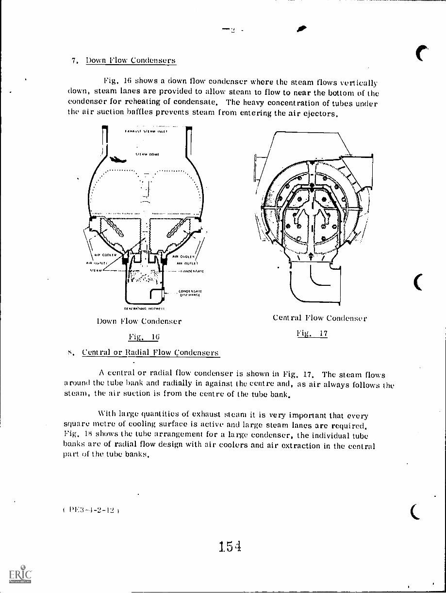
7. Down Flow Condensers
Fig. 16 shows a down flow condenser where the steam flows verticallydown, steam lanes are provided to allow steam to flow to near the bottom of thecondenser for reheating of condensate, The heavy concentration of tubes underthe air suction baffles prevents steam from entering the air ejectors,
nr.NeTANf: /40/WI I
Down Flow Condenser
Fig, 16
s, Central or Radial Flow Condensers
Central Flow Condenser
Fig. 17
A central or radial flow condenser is shown in Fig, 17, The steam flowsaround the tube bank and radially in against the centre and, as air always follows thesteam, the air suction is from the centre of the tube bank.
With large quantities of exhaust steam it is very important that everysquare metre of cooling surface is active and large steam lanes are required,Fig. 18 shows the tube arrangement for a large condenser, the individual tubebanks are of radial flow design with air coolers and air extraction in the centralpart of the tube banks,
1)1.:3-1-2-12
15

- 1:;
Large Condenser with Radial Flow Tube Banks
Fig, 18
The Jet Condenser
This type of condenser uses the principle of spraying cooling water intodirect contact with the incoming exhaust steam in order to condense it, The com-bined cooling water ( coolant ) and condensed steam ( condensate ) is then taken tothe hotwell,
The feed pump draws from this hot yell only the quantity of feed requiredby the boilers, the remainder overflows into the cooling pond where it is cooledand returned to the condenser again as cooling water.
This arrangement has the definite disadvantage that the entire cooling%%.ater quantity must be chemically treated to maintain boiler feed water purity,and for this and other reasons there arc very few jet condensers in operation today,
PE31-2-13 )
155

Stemn In
- 14 -
Fig. 19 shows diagrammatically the operation of a jet condenser.
CoolantIn
Steam In
Jets
Airextraction
Condensate and coolant
Jet Condenser
Fig, 19
Fig. 20 ( a) and ( b) show two methods of application of the jet condenser.
Air Extraction
Air Extraction
(a)
1)1.::i-1-2-14
Jet Condenser Applications
Fig. 20
(b)
156

- 15 -
In Fig. 20 ( a) the condenser is set at a low level, the air and condensateare pumped from the condenser and the cooling water is induced to flow in byvacuum,
In Fig. 20 ( b) the condenser is set about 35 feet above the level of thehotwell so that the head of water ( condensate and coolant ) in the discharge pipeis sufficient to cause it to fall into the hotwell against the vacuum in the condenser,without pumping. This is a so-called "barometric leg ". The cooling water mustbe pumped into the condenser and the air pumped out.
Finally, the ejector condenser is a special form of jet condenser.
The cooling water flows into the condenser body through a series of con-vergent nozzles which increase its velocity, steam from the engine exhaust isinduced into this cooling water flow and condensed by direct mixing.
The ejector condenser is suitable only for moderate vacuum. Fig. 21illustrates the ejector condenser.
Water Inlet
Steam
Inlet
Condensate and discharged coolant
15/
Ejector Condenser
Fig. 21
14:31-2-15 )

Condenser Auxiliaries
It is impossible to avoid small quantities of air entering a steam turbinesystem in the areas which are under vacuum. These small air quantities accumu-late in the steam space of the condenser and must be removed continuously as theabsolute pressure in the condenser according to Dalton' s Law is the sum of allpartial pressures or the sum of the steam pressure and the air pressure; thus theair increases the condenser pressure and may air blanket part of the coolingsurface.
The usual means of extracting the air is by means of an air ejector,although in some cases an air pump, either reciprocating or rotary, may be usedfor this purpose.
I. The Air Ejector
In the ejector, high pressure steam is allowed to expand through a nozzle,thus converting its heat energy into kinetic energy and producing a high velocityjet at the nozzle discharge. This jet is used to entrain air and other non-conden-sibles and draw them from the condenser space. Most condensers have baffleplates to guide the air to special air coolers at the air extraction points.
Fig. 22 shows a two-stage steam operated air ejector. High pressuresteam up to 3000 kPa is supplied to both nozzles and allowed to expand through asmall orifice. The resulting high velocity steam entrains gases from the con-denser and carries them into the first stage shell- and-tube condenser. Herethe steam is condensed and the remaining non condensibles are drawn off againby being entrained in the steam jet from the second stage nozzle.
The steam is condensed in this stage but here the pressure is maintainedslightly above atmospheric pressure so that the remaining air and gases can bevented to the atmosphere. The condensed steam is drained off to a drains tank.
The pressure in the first stage ejector cooler is below atmospheric butabove condenser-pressure and the condensed steam is drained back to the con-denser; a loop seal on the drain piping prevent recirculation of non-condensibles.
For high vacuum three-stage ejectors are used and the second-stageejector cooler condensate is drained via a loop sealed drain pipe to the first-stage.
1)1:31-2-11) )
158

- 17
111.1 ,4 rims 41111citt(titMINIMI#011111
14 !AIL i!
0 I: 0 ' , ';,i.. ti !111,
_..i., ..ire,..jimil - dll.1111111==
iTril FA, 1 r:C.iioloi7
Section of a twostage air elector with irter and aftersurface coolers.
Fig, 22
The cooling water for the ejector cooler in Fig, 22 is condensate fromthe extraction pump, it enters at M1, flows through the inner tubes N to theclosed top of the outer tubes 0, down through the outer tubes to chamber P1 overto chamber P2, up through the outer tubes and down through inner tubes and out
at M2. The use of condensate makes the ejector coolers a kind of feedwaterheater recovering the heat losses of the jet steam,
The orifice of the ejector nozzle is extremely small and care must betaken to see it does not become choked with foreign matter from the supply steampipes, A fine mesh steam strainer is usually fitted upstream of the nozzles forthis reason, Water ejectors working on the same principle as the ejector con-denser ( Fig. 21 ) are often used as air ejectors, The ejector is supplied withcooling water from a booster pump at (301) to 800 kPa,
1)1 :i-- 1-2-17 I
15J

1
2. Condenser Safety Fittings
-
A condenser would not be complete without certain safety fittings, designedto protect both the condenser and the turbine exhausting into it, against possibleoperating troubles, The main dangers to be guarded against are: an increase inback pressure, a rise in condensate level, and contamination of condensate.
a) Atmospheric Relief Valve
The condenser is a closed vessel and therefore it would he possible forthe back pressure to rise until it was above atmospheric pressure if, say, thecooling water flow stopped while the condenser was on load. A condenser shellis not designed to withstand a pressure from the inside and would soon burst.
The atmospheric relief valve is designed to open if the pressure in thecondenser rises above atmospheric and allow the steam.to escape from the shell.Under normal operating conditions this valve is held closed by the difference inpressure between the atmosphere outside and the vacuum in the shell. In orderto ensure that air does not leak past the valve into the condenser, it is usuallyfitted with a water seal. It operates on a balanced lever and should be tested atfrequent intervals when the machine is off load to ensure that it is quite free.
Note that since the purpose of the atmospheric relief valve is to vent thefull flow of exhaust steam to atmosphere it is necessarily of considerable size.
For large condensers the atmospheric relief valve is replaced withexplosion diaphragms on all L. P. turbine exhausts. Other protect ive devicesfor condenser pressure are: vacuum pay-off relays and vacuum trip relays. Thevacuum pay-off relay is incorporated in the turbine governor system and is usuallyset to operate between 10 kl)a and 10 kPa absolute pressure, so that unloading ofthe turbine begins at 10 kPa and the turbine is fully unloaded at .10 k
The vacuum trip relay is set to trip the turbine at 50 kPa.
I) ) Condenser (;age Glass
This gives a clear indication of the level of the condensate in the conden-ser hotwell, The top and bottom of the glass are connected above and below thewater level and the whole of the fitting is under condenser vacuum.
care must he taken to that there arc no air-leaks in the litting,particularly through the cocks. A board, painted with diagonal stripes and placed
160

19 -
behind the glass makes the water level easier to read,
c ) High Water-Level Alarm
The indication of condensate level given by the gage glass is often supple-mented by a float-operated alarm to give warning of high-water level.
A steadily rising condensate level would very quickly seal off the airoutlet, the vacuum space would become filled with non-condensible gases, theback pressure of the exhaust steam would increase and the turbine output wouldfall.
d) Detection of Cooling Water Leaks
If a condenser tube is damaged, or a ferrule begins to leak, cooling watercan find its way into the steam space of the condenser and contaminate the con-densate, It is most important that this can be recognized at once and corrected.There are several methods employed for this purpose, the most common beingan electrical purity measurement,
Cooling water is a very good conductor of electricity because of itsimpurities, whilst the very pure condensate is a non-conductor. Leakage ofcooling water into condensate may therefore be detected by taking readings ofthe electrical conductivity of a sample of condensate in a dionic tester,
The presence of salt in water can be detected chemically by the silvernitrate test, this method can be used when the cooling water is salt. When thecondensate sample contains traces of sodium chloride, the sample will turnmilky-white when a few drops of a silver nitrate solution is added. When leakagehas been confirmed the repair must be made as soon as possible.
If the condenser is of the single flow type, the condenser must be takenout of service for repair. When the turbine is shut down, the waterboxes aredrained and the inspection doors opened.
The steam space can be filled with clean water, but before doing so, thesupporting or jack-screws should be applied to carry the weight of the condenser.
With the steam space under water pressure the water will leak out ofthe leaky tube. However, the leaks detected by the conductivity meter may bevery small and approximately 25 grams of fluorescin dye, a yellowish-red cry-stalline compound may be added. The water from the leaky tube will then show up
( 14:3-4-2-19 )
161

- 2U -
fluorescent green in the light of a special detector lamp.
Large condensers are usually of the double flow type with tubes expandedat both ends and have the advantage that leaky tubes may be located and pluggedwhile the unit is at 50% load or less. The procedure is: drain one side of thewaterbox, the conductivity meter will indicate if that is the leaky side or not.When the leaky side is detected, it is drained.
It is very important to isolate the air ejector suction on the drained side,because the air ejector will be choked with steam as the air cooler is out ofservice. With a clear plastic hose hooked up as gage glass for the waterbox, itis filled, say, 25 cm at a time and the conductivity meter is checked each time;when conductivity shows the leak, it should be within 25 cm of the waterlevel andthat area will, as soon as the waterbox is drained again, be investigated for leaksby covering the tubes at both ends with thin household plastic wrapping taking asmall area, say, 25 x 50 cm at a time. The condenser vacuum will suck theplastic in at the leaky tube, when the plastic bursts the leak is located. The tubeis plugged at both ends with wooden plugs and the condenser is brought back intoservice again.
c) Air Leaks
Air leaks may be quite large, approximately 4 - 5 mm in diameter,before they interfere with the vacuum. The air ejector can usually handle anyleak smaller than that. There is in most cases only one way to detect an air leak,that is to shut down the turbine and condenser and fill the low pressure heatersand the condenser steam space right up to the. turbine blades with water, and theleaks should not be difficult to locate.
3. Circulating Water ( ) Pumps
These pumps, which are also referred to as cooling water pumps, arcused to pump water through the tubes in a surface condenser. The water is usu-ally pumped from a river or lake and after passing through the condenser isreturned to the river or lake once again. In locations where there is a watershortage, the water, after leaving the condenser, is cooled in a cooling tower andreturned once again to the condenser for re-use.
PE3-4 -2-20 )
162

21 -
A type of pump commonly used for circulating water service is thevertical pump shown in Fig. 23. It may be an axial-flow, also called propellertype pump, where the impeller is the shape of a ship's propeller; or it may be a"mixed -flow "pump obtaining its pump-ing action from a mixture of centrifugalforce and the lifting effect of the impel-ler vanes. The pump bearings may be Pum
oil lubricated bronze or babbitt lined Motor
bearings or they may be nylon- or hardrubber-bearings with clean water in-jected at the centre of the bearingsfor continuous flushing and lubrication.
The vertical design makes thepump length variable by adding moresections of pump casing and shaft.This is important as the impeller mustbe submerged for proper operati );and it also eliminates the need 'priming the pump.
The axial thrust on the impel-ler caused by the discharge head to-gether with the weight of impeller,shaft and the rotor of the motor iscarried by a large Kingsbury thrustbearing at the top of the motor.
For large condensers thepropeller pump_ has been replacedwith large single stage, .double suction,vertical centrifugal pumps, a designthat eliminates axial thrust.
The same type of pump, butin a small and horizontal version isoften used for small condensers.
If not submerged the centrifugalpumps must have an arrangement for,...(priming.
Discharge-)
163
+-Level ofImpeller
e_ Suction
Vertical Mixed Flow CW Pump
Fig, 23
1)1.;:i -2 -2 1 )

4. Extraction ( Condensate ) Pumps
The function of the extraction or condensate pump is to continually extractthe condensate from the condenser hotwell and pump it through air ejector coolersand low pressure heaters into the deaerator.
Except for handling clean condensate, the extraction pumps operate undervery severe conditions as the suction pressure is near absolute zero pressure,the condensate is near the bailing point at the entrance to the pump and it mustkeep nearly constant level in the hotwell at any load on the condenser. It is stan-dard practice to have two 100% extraction pumps for each condenser.
The extraction pump is usually a centrifugal pump with two or threestages. Fig. 24 shows a two-stage horizontal extraction pump, the first stagehas a double suction impeller and discharges the condensate in a split stream tothe two opposed second-stage impellers working in parallel.
in)
i. .1
ori
f evi., $
t ;11l1-2471-17- 'it
:1--tk el
L:..
Horizontal Two StageExtraction Pump ( Allis-Chalmers )
Fig, 24
The glands are waterscaled, to prevent the entrance of air when thepump is on stand-by, in service the glands are exposed to the pump dischargepressure. For the proper operation of an extraction pump, the pump must havean air release connection from the pump discharge back to the condenser, or asmall equalizing connection from discharge back to the suction. When the pumpduring low load loses the condensate, the pressure across the pump will equalizethrough the equalizing connection, or the air,r0,,ase; and condensate will againbe extracted from the condensers as it becomes available for the pump.
Thu very low N. P.S.11, of extraction pumps makes cavitation much Inurecommon in these pumps than in any other pumps, or reduced cavitation the vert-ical well type extraction pump Pig. ) is preferred. The flange of the well is
)

level With the floor and the suction head is increased, The well is air-tight withan air-release line leading back to the condenser, These pumps have the advantageof better performance and less cavitation,
Vertical Condensate Pump
Fig. 25
kill Multistage CondensatePumps of the Turbine Type
Fig, 26
165
)
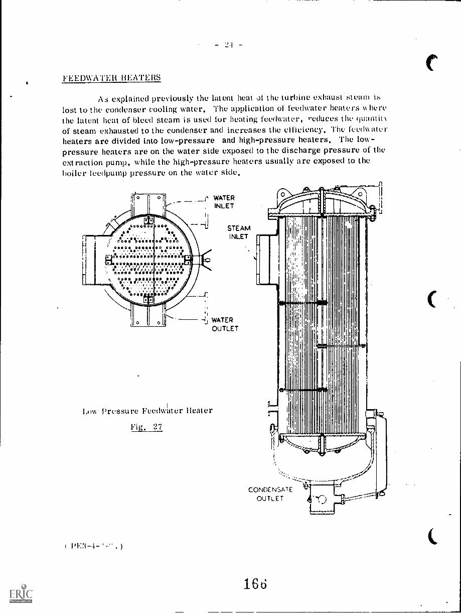
IFEEDWATER HEATERS
As explained previously the latent heat al the turbine exhaust swain islost to the condenser cooling water. The application of feedwater heaters k herethe latent heat of bleed steam is used for heating feedwater, "educes the quantitof steam exhausted to the condenser and increases the efficiency', The fe'c(k
heaters are divided into low-pressure and high-pressure heaters. The low-pressure heaters are on the water side exposed to the discharge pressure of theextraction pump, while the high-pressure heaters usually are exposed to theboiler feedpump pressure on the water side,
10064
1,S0000 Q GOO09e.
ewes Ve.e.e e Ve.ellosoot?. rises So eases1 ...$s...4.EiCS4.0'41.0VS'S'O'S'0 sOsSOSO
",614PM.Aik,'411:,1.4606OseSe 0sSVI SS OsSee
\\ op..° JDOIM09 00 OOSo°,,' .°.".' . ."
DG
PO. ..., ..... ./t.e0100 0 see
WATER, INLET
STEAMINLET
-1,1 WATER
OUTLET
Enw Pressure Feedwater Heater
Fig. 27
CONDENSATEOUTLET
166

- 25 -
Fig, 2S shows the feedwater heater system for a large steam turbine.The condensate passes through the air-ejector coolers, drain-cooler, low pres-sure heaters into the deaerator heater.
The boiler feed pump then pumps the deaerated water from the deaeratorthrough a series of three high pressure heaters to the boiler. The feedwaterheaters, both high pressure and low pressure, and the deaerator are all suppliedwith steam bled from various stages of the turbine.
Bode.
SleaM 10 Mt eptC1011
P11
-rt., 00,, 0
Nn 1,01.114
(am
1 Gland1 Cnrrfonir,
. 4 -
16?
L
L Or410
Ontlenwt
t.,,,,Pump
Feedwater Heater System
Fig, 20
BEST COPY AVAILABLE
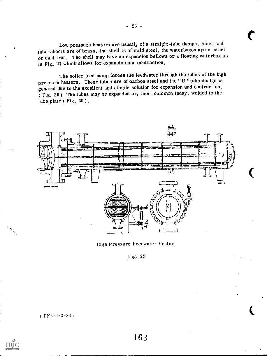
- 26 -
Low pressure heaters are usually of a straight-tube design, tubes andtube-sheets are of brass, the shell is of mild steel, the waterboxes are of steelor cast iron. The shell may have an expansion bellows or a floating waterbox asin Fig. 27 which allows for expansion and contraction.
The boiler feed pump forces the feedwater through the tubes of the highpressure heaters. These tubes are of carbon steel and the "U "tube design isgeneral due to the excellent and simple solution for expansion and contraction,( Fig, 29) The tubes may be expanded or, most common today, welded to. the
tube plate ( Fig. 30 ) .
41. apc.A..111111SIMON al.
11111111 11
001041110 WHEN
( PE:3-4-2-26 )
mr. - !..111.111
......t ...111114.17.,........ - .:- ...r...--.
)
Xfl
(V it
High Pressure Feedwater Heater
Fig. 29
16d
111111111

4
a
0"«I
Stdges of tube welding process
a. The tubes and the holes in the tube plate arethoroughly cleaned; a ring is placed over the pro-truding tube ends and the end part of the tube isslightly expanded
b The ring made of special alloy ;s melted using anautomatic argon arc welding gun.
c The weld is checked for gas-tightnessd The spaces between the tubes are filled up by
hand welding; this is followed by heat treatment andsurface treatment.
lit utcr fittings
Fig. 30,
For the operation, maintenance and safety of feel lwate r heaters, thefollowing valves are installed:
Safety Valve on steam side.
Relief Valve on the waterboN to prevent exeessiv(... pressure (kit to thermo Iexpansion of the water when the wat(,rside is isolated.
1. 5'
PE3-4-2-27

- 28 -
Bleed Steam Stop Valve and Non-return Valve - the non-return valve preventssteam from the heater entering the turbine, which may occur when the turbineload is suddenly reduced. This causes the bleed steam pressure to decrease andpart of the condensate in the feedwater heaters flashes into the steam, which ifallowed to enter the turbine, would cause it to increase speed after the overspeedtrip has closed the turbine main stop valve.
Drain Valve on steam side for draining oft condensate.
Drain Valve on water box for draining off waterside for maintenance.
Air-release Valve on steam side for air-release to the condenser, as airtrapped in feedwater heaters prevents steam from coming in contact with the air-bound tubes. A lam-pressure heater with isolated air-release connections maybecome completely air-bound and no heat at all will be transferred to the feedwater.
The condensate from the steam space of a feedwater heater passesthrough an orifice plate in the drain line and drains to the steam space of a heaterat lower pressure, see Fig. 28. For vertical heaters the orifice plates providesufficient water level control for the heaters. The water level is much morecritical in horizontal heaters and automatic level control valves are usuallyrequired.
If the drain from the first low-pressure heater is allowed to drain backto the condenser, a considerable amount of sensible heat is lost in the condenser.This can be prevented by the installation of a drain cooler ( Fig. 31 ). The con-densate leaving the air-ejector coolers flows through the tubes of the drain coolerand most of the sensible heat of the drains is absorbed, before they are allowedto enter the condenser. In many installations a condensate return pump, replacingthe drains cooler, returns the condensate from the heater steam space back tothe main condensate pipe at the outlet from the low-pressure heater, in whichcase all the sensible heat from the drains is reclaimed.
1)113--1-2-2ri
1 7 o

Drain Inlet
Lifting Hole
WaterOutlet
WaterIn
(
- 29 -
InspectionHo
Air Release
LiftingAok
Air Cock
InspectionHole
Watergage Connections
Position ofLongitudinal Joint
Tubes expandedat both ends
DrainOutlet
Sectional End Elevation
Drain Cooler ( C.A.I). Design )3l
171
( 4 -2-29 )

- 30 -
DEAERATORS
The deaerator or deaerator-heater serves a dual purpose as it heatsand deaerates the condensate.
Thermal deaeration is accomplished by heating the condensate to theboiling point liberating all dissolved gases. The deaerator must be designed toheat the condensate to the boiling point at the rate at which it is pumped by theextraction pump. This is usually accomplished by mixing steam and condensate.A mixing-deaerator of simple construction is shown in Fig. 32. At the top of thedeaerator the condensate flows through a nozzle into the top of the steam chamber,where it mixes with bleed steam increasing the temperature to near the boilingpoint. The water cascades in a thin sheet down over a series of trays, wheremost of the deaerating takes place.
The deaerator is usuallylocated on top of the feedwater tank,( deaerator and tank are generallyconsidered as a unit and called thedeaerator ). The deaerated conden-sate flows down into the tank whilethe non-condensible gases flow to thetop, where they are vented off to themain condenser.
It is very common to installa vent or vapor condenser on thetop of the deaerator as shown inFig, 33,
Brown I3overi Deaerating MixerHeater
Fig. 32
( 14:3-4-2-30 )
1

STEAMINLET
- 31 -
VENT WATER INLET
DISTRIBUTIONTRAYS
Vil411 4 .T.,
Mai l'ill=11.1cjigi'MPIs.,-111101111101,
marM11111111aap43 Fily-ms tilli)i .-RAIN
TRAYS
Tray-type Direct-contact Heater( Foster Wheeler Corp. )
Fig. 33
DRAINRETURN
The condensate from '..he L. P. heater flows through the tubes of the ventcondenser before entering the deaerator, The non-condensibles and water vaporsenter the vent condenser and flow around the tubes, the vapors condense and re-turn, through a loop-sealed drain pipe,to the deaerator, The loop-seal preventsrecirculation of non-condensibles. The non-condensibles are drawn off from thetop of the vent condenser to the main condenser, The vent condenser reclaimsthe latent and sensible heat of the vapors.
The non-return valve in the bleed steam piping to the deaerator preventsthe deaerator from acting as a steam accumulator supplying the turbine withsteam after a sudden load reduction,
( 14:3-4-2-31 )
173


The shell is made of fabricated steel, the rear end of the shell is closedby a welded-on formed head, the front is open with a welded-on hub-type forgedflange. The front cover is a formed head with a welded-on heavy flange. Thelarge front cover bolted to the shell allows for removal of the entire coil andheader assembly which is supported on a steel frame equipped with flanged wheelsrolling on tracks fastened inside the shell,
The steam coils are all in parallel and fastened to the top and bottomheaders which allows for free draining. The coils have several loops making themvery flexible allowing descaling by cracking.
Baffles on top of the coils and under the vapor outlet separate water fromthe vapor, This evaporator is designed for operating with raw water, but treatedor softened water is often used, depending on the quality of the raw water and therequired quality of the distilled water,
As water evaporates, the dissolved solids are left behind increasing thetotal dissolved solids in the water inside the evaporator. The evaporator mustbe blown down frequently in order to keep the dissolved solids inside limits, toprevent foaming and carry-over.
As a pressure vessel the evaporator must have a safety valve. Thebleed steam inlet must have a stop and non-return valve, and the coil drain shouldhave steam traps or for large evaporators water level control valves. A floatcontrol valve maintains the water level and a gage glass is installed directly on tothe shell and indicates the water level.
Good heat transfer requires clean heating surfaces. A fast and effectivecleaning method is cracking where the evaporator is drained and steam is admittedto the coils. The expansion of the hot tubes may crack some of the scale. Thenthe steam supply is shut off and cold water is sprayed over the tubes. The con-t ruction of the tubes cracks off more scale. Repeating the cracking procedureseveral times takes care of most of the scale, but every so often the coil assemblymust be taken out for nomplete cleaning of the coils as well as the inside of the
P3 )
176
- 34 -
COOLING TOWERS AND PONDS
If a sufficient and suitable supply of cooling water for the condenser isnot available, then some means must be used to re-cool any water that is availableso that it can be used over and over again.
To achieve this, either cooling towers or cooling ponds are used and inboth methods the warmed water is cooled by exposure to the atmosphere and sub-sequent evaporation of a portion of the water.
In the case of a cooling pond, the warm water is discharged to a pond ofsufficient area to allow it to be cooled by contact with the air at the surface of thepond. If the water is sprayed into the air above the pond surface, then the pondarea can be considerably reduced as the spraying will provide additional contactbetween water and air.
In the case of a cooling tower, the warm water is delivered to the top ofthe tower and falls by gravity over an arrangement of splash bars ,to a reservoirat the bottom. The air is caused to rise up through the falling water by naturaldraft or by mechanical draft. The natural draft type uses a chimney or stack toinduce a flow or air through the tower while the mechanical draft type uses a fanto cause the air flow.
Natural Draft Tower ( Hyperbolic Type )
The hyperbolic natural draft cooling tower consists of a lower and anupper portion. The lower portion is the cooling section which contains wooden
splash bars over which the warm water falls as it travels to a collecting basin orreservoir directly below the splash bar section, The air enters around the peri-meter of the splash bar section, The upper portion of the tower is a hyperbolic
shaped section constructed of reinforced concrete. This section acts as a chimneyto induce the flow of air through the cooling section.
The hyperbolic tower has the advantage of high capacity, low power con-sumption, long service life and a minimum of maintenance. It does, however,have a high initial cost. The sketch in Fig. 35 shows the general arrangement of
a hyperbolic tower.
( 1,1..3-4-2-34 )
1 76

WATER Ou
Mechanical Draft Towers
- 35 -
CHIMNEY SECTION Hyperbolic Tower
Fig. 35
The mechanical draft tower may be either a forced draft type, or aninduced draft type.
In the forced draft type, the air for cooling is forced through the towerby a fan which is located at the base of the tower,
In the induced draft type, the fan is located at the top of the tower anddraws air in through louvres situated around the tower base. The air passesupwardly through the falling water and then passes through baffle type drift elim-inators which separate any entrained moisture from the air, The air is thendischarged at a relatively high velocity by the fan.
The induced draft tower is more commonly used than the forced drafttype as it has the following advantages:
1. As the air is discharged at high velocity, it is not likely torecirculate back to the inlet around the tower base,
2. The fan is not likely to ice t p a it is in the path ch. the warmedair being drawn from the tower,
3. The noise of the fan is not so noticeable as it is located at thetop of the tower rather than at the bottom,
An induced draft tower arrangement is sketched in Fig, 36,
177
( PE3-4-2-35 )

I
WATER
AIR1 OUTLET
FAN
>>>>> >>>>>>>>>>>>>>
INLET
AIRINLET
11.1. ---nsAff-6A I IA.16(14'i
- 36 -
DRIFTELIMINATORS
DIS rRiBU !MNSYSTEM
AIRINLET
STARTING AND STOPPING STEAM TURBINES
Induced Draft Tower
Fig. 36
In the following sections the general methods of starting and stoppingnon-condensing and condensing Steam turbines will be discussed. It is not possibleto give detailed instructions because of the large number of different makes anddesigns of these machines, each of which differs in some detail from the others.Therefore the plant personnel who are required to operate the particular turbineshould consult and become familiar with the instruction books issued by the manu-facturer of the machine.
Starting a Small Non-condensing Turbine
1, Check that governor linkages are well lubricated and grease cupsif used are filled. Check oil level in bearing sumps if bearingsare ring oiled or check level in main oil reservoir if a pressurelubricated system is used.
2. Make sure that all condensate is drained from steam lines andexhaust lines. If these are normally drained by means of trapsthen open by-pass lines around traps.
3. Slowly open the shut-off valve between the turbine and the exhaustline.
4. If the turbine is equipped with a pressure lubricated system havinga separately driven oil pump, then start the pump. Check thatsufficient oil pressure and flow is established.
( PE3-4-2-36 )

:37
5. If bearing oil sumps or oil reservoirs are water cooled, thenturn on water supply to them.
G. Partly open the throttle valve quickly to start the turbine rotorturning. Then close the valve again to the point where the rotorcontinues to turn slowly. Listen carefully for any noise thatindicates rubbing of the rotor against the casing. In case of ring-lubricated bearings check the operation of all lubricating rings.
7. If no unusual noises are detected, increase the turbine speedto between 200 and 300 rev/min. Maintain this speed for about onehalf hour to allow rotor and casing to reach operating temperature.
8. Trip the overspeed valve by hand to check its operation.
9. Restart the turbine as in Item 6 and bring turbine up to rated speed.Check that as the machine approaches this rated speed, the governortakes over control and maintains this speed. The throttle valve maynow be opened wide.
10. If a main oil pump driven by the turbine is installed then the separatelydriven auxiliary oil pump may now be shut down. Check oil pressureand flow once again,
11. Steam line drains and trap by-passes may now be closed.
12. Increase load on turbine gradually.
Stopping a Small Non-condensing Turbine
1, Reduce turbine load to zero.
2. If a separately driven auxiliary oil pump is used, start this pump,
3. Shut off steam supply to the turbine by manually tripping the over-speed trip valve. Then shut the throttle valve.
4. Shut off water supply to oil coolers.
4, When turbine comes to rest, shut the exhaust line valve.
17J
( P 1.;:i )

- 38 -
Startinut barge Condensing Turbine
1. Two to three hours before steam will be admitted to the turbinestart the lubricating oil pump. The pump supplies lubricatingoil at 75 to 100 kPa to the bearings.
2, Start the jacking oil pump which supplies lubricating oil at 8000 -1.0 000 kPa to the bottom of the bearings in order to float the shaft.
3, Engage and start the barring gear. The barring gear is usuallyelectrically interlocked by a lubricating oil pressure switch andand engagement switch.
4, When the barring gear is up to speed, shut down the jacking oilpump.
5, When the turbine has been barring for two to three hours, opendrain valves on steam line and turbine casing and open trapby-passes,
6. Start auxiliary oil pump. If it is automatic, turn selector switchto " auto "to start the pump. This is a separately driven oil pump.which supplies lubricating oil at 75 - 100 kPa and governor oil at550 - 650 kPa during start-up and shut-down periods.
When the turbine is in normal operation this oil is supplied by themain oil pump, which is driven by the turbine shaft, The mainoil pump pressure is set slightly higher than the auxiliary oilpump pressure in order to make an oil pressure switch shut offthe auxiliary oil pump when the main pump takes over.
7. Shut down lubricating oil pump. If automatic it should shut downwhen the auxiliary oil pump takes over,
8, After starting the auxiliary oil pump, check the oil pressure pro-duced, the oil flow to each bearing and the oil reservoir level.
9, Start the circulating water pump and establish circulating waterflow through the condenser.
10. Start the extraction ( condensate ) pump and circulate condensatethrough the air ejectors,
11. Admit sealing steam to the turbine glands.
12. Put the air ejector into operation and draw a partial vacuum onthe condenser,
)
- 39 -
13. Open the throttle or steam admission valve just enough tostart the turbine rolling.
14. Trip the overspeed valve by hand to see that it is free tooperate.
15. Restart turbine as in Item 13 and maintain it at a low speedwhile checking around the turbine listening and looking foranything unusual.
16. Gradually admit more steam to turbine in order to slowlyincrease the speed. If any unexpected vibration occurs thendecrease speed again and continue warming up until turbine runssmoothly when the speed is next increased.
17. Check that the governor takes over control when rated speed isreached.
18. In some machines there is a manual over-ride on the governor thatcan be used to actually overspeed the turbine in order to test theoverspeed trip mechanism. If this is the case, the overspeed tripshould be tested by this method at this point.
19, Reset the trip mechanism and bring the speed back up to normalonce again.
20. When the oil has reached the normal operating temperature, admitcooling water to oil coolers to maintain desired oil temperature,
21, Stop the auxiliary oil pump and check that the main oil pump ismaintaining correct oil pressure.
22. The steam admission valve may now be opened fully and the turbineload slowly increased to the desired point,
23. Drain valves may now be closed,
.)topping a Large Condensing Turbine
1, Reduce turbine load gradually to zero,
2, Shut off steam to turbine by manually tripping the overspeed trip,or by closing the steam stop valve manually,
3, Shut down the air ejectors and break the condenser vacuum,
4. Shut off cooling water to oil coolers, Sub-cooling of lubricatingoil should be avoided.
( PE3-4-2-39 )
181.

10 -
5. As the turbine speed decreases, see that the auxiliary oil pumpstarts automatically at the correct point, If not automatic, startthe auxiliary oil pump when the turbine speed is down to approxi-mately 75qt,
6, Shut off gland steam.
7. Shut down the extraction pump.
8, Open the steam drain valves.
9. When the turbine comes to a standstill, switch the auxiliary oilpump switch to "off "and the lubricating oil pump should startautomatically.
10, Engage the barring gear.
11. Start the jacking oil pump.
12, Start the barring gear,
13. When the ',Jarring gear is up to normal barring speed shut downthe jacking oil pump,
14, When the machine is cooled off, stop the circulating water
1. ., Keep the turbine barring for 24 hours, then shut down the barringgear, it should disengage automatically, but check for properdisengagement,
16, Shut off the lubricating oil pump,
( 14:3-4-2-40 )
182

QUESTION SHEET
Power ring
Third Class_Sect. Lect.
1, a) Explain the purpose of an evaporator and describe howthis purpose is achieved.
b ) What causes high concentration of solids in an evaporatorand how is this concentration controlled'?
2, Sketch a typical deaerator and describe its operation.
Sketch a typical low pressure or high pressure feedwater heater.Include all necessary valves and fittings..
1. List three purposes of a surface condenser and explain how eachpurpose is achieved.
5. Sketch and describe the operation of as two-stage steam operatedair elector, including ciector coolers with condensate drains.
Describe one method 01 locating a leaking condenser tube.
7. List three operating, troubles ot a condenser and explain why eachis undesirable and how each may ht. guarded against.
Explain how and why condenser pressure will vary with changesin turbine load.
. Describe the principle of operation of a direct contact condenserand give a disadvantage of this type.
W. Vol' a steam turbine, with which You arc familiar, list importantdata, such as manufacturer, siv.e, type, rpm, inlet and exhauststeam pressure; then describe the method of starting and stoppingthe turbine.
183 1)1.:3 i -2 -Q )

' .swarnorapowsesmammempar ,aw
.111.1r4=011.61.1.1A-TPIG YeNLMill
8.4
STEAM TURBINES -- OPERATION AND MAINTENANCE
Goal:
The apprentice will be able todescribe steps in operating andmaintaining steam turbineequipment.
Performance Indicators:
1. Describe starting procedures.
2. Describe operational procedures.
3. lescribe stopping or shut-downprocedures.
4. Describe routine maintenance.
5. Describe instruments, controlsand supervisory equipment.
184

INSTRUCTIONAL LEARNING SYSTEMS
Study Guide VIP
* Read the goal and performance indicators to find what is to be learned from
package.
Read the vocabulary list to find new words that will be used in package.
Read the introduction and information sheets.
Complete the job sheet.
Complete self-assessment.
Complete post-assessment.
2
185

IN1 I SUL11LAWAL LttitlisalsAA'W J I CPA.)
Vocabulary* Alignment
Blade fouling
Bridge gauge
Clearances
Diaphragms
Glands
Horizontal eccentricity
Kenotometer
Supervisory equipment
Vertical eccentricity

1Nb, I ERA,. 110181AL. LtAtiNINta b Y b I tIVI
Introduction
0
Steam turbine equipment is constructed In many types and configurations. Eachassembly will have unique features. The manufacturers instruction manual shouldbe followed in the operation and maintenance of steam turbine equipment. Safe
operation depends on following the recommended procedures in a sequential
manner.
This package will describe the general procedures for operating and maintaining
steam turbines. Apprentices ssiould learn the general procedures and then turnto operator manuals for information on the operation of specific turbines.
4
187

INSTRUCTIONAL LEARNING SYSTEMS
InformationSTARTING A TURBINE
New Turbines
When starting a new turbine for the first time, the operator should take greatcare to see that the internal parts of the turbine are clean. Feedpipes,condensers and other equipment should be cleaned to keep dirt out of the turbineblades. The system should be well lubricated before it is started for the firsttime. All safety devices, gauges and seals must be inspected or tested toassure that they are functional.
Starting Instructions
1. Check the condensing plant. Start the circulating pump. Make sure thatpipes and water boxes are full of water and clear of air.
0 2. Check lubrication system. Start auxiliary oil pump and check bearings andvalves for oiling. Start jacking oil pump.
3. Engage turning gear to run rotors for warm-up period.
4. Set drains on turbine and steam lines. Open by-pass steam valves.
5. Seal turbine shaft glands and build up vacuum in condensing plant.
6. Start condensate pump and open recirculating valve on condenser.
7. Test emergency trip gear. Shut stop valves and by-passes and open emergencystop valves and test with trip gear.
8. Open stop valve enough to start engine rolling.
9. Close down the turning gear.
10. Bring turbine up to running speed.
5
188

INSTRUCTIONAL LEARNING SYSTEMS
°InformationOPERATING A TURBINE
Operational Procedures
1. Test overspeed trip after governor has taken over control.
2. Check the following before loading:
- Bearing oil pressures and temperatures- Condenser vacuum.- Steam drains- Condensate recirculating valve- Thrust adjustment on spindle- Auxiliaries such as feed pumps and extraction Pumps
3. Keep careful watch on bearing temperatures, vibration and noise duringloading.
4. Engage lubricating oil coolers as needed to control temperature of turbine
bearings at or near 50 C.
5. Monitor the turbine under load for temperature and pressure of bearings,
noises and vibrations. The operator should have some standards for normal
operation with which to compare readings. Under load, the turbine
pressures will be constant for that specific load. Experience will enable
operators to recognize changes from the normal operating temperatures and
pressures.
6. Check the back pressure (exhaust vacuum) by use of a kenotometer.
SHUTTING DOWN A TURBINE
flaking the Turbine
1. Set thrust-adjusting gear for maximum clearance.
2. Open condensate recirculating valves.
3. Open main alternator switch after all load has been removed.
6
18
INSTRUCTIONAL LEARNING SYSTEMS
Information4. Check overspeed trips.
5. Close stop valves on turbine.
6. Shut down air ejectors to destroy vacuum.
7. Open all turbine drains.
8. Check the auxiliary oil pump to see that it starts to operate as turbine
speed is decreased.
9. Engage the turning gear.
10. Shut off cooling water valves to the oil coolers to retain heat in the oil.
II/
11. Shut off extraction pumps and circulating water to the condenser.
MAINTENANCE OF TURBINES
Blade Fouling
Turbine blades must be kept clean and free of dirt and scale deposits. The
cleaning may be done by washing or mechanical means. The turbine can be washed
by forcing wet steam through the stop valves. With the cylinder drains open,
the operator can determine when the purity of the liquid drain indicates a cleanturbine. Washing will not remove scale deposits. A mechanical cleaning must be
used to remove insoluble materials. This material can be removed by blasting
the surfaces with an abrasive material. A complete cleaning should take place
during overhaul while the turbine is dismantled. During overhaul, the blades
should be inspected for erosion and cracks. Damaged blades should be repaired
or replaced.
Glands
The operator can detect problems in the shaft glands by the amount of steam
required for sealing. During overhaul, the gland packings must be cleaned,
adjusted for clearance or straigh4.ened as needed.
7
190

INSTRUCTIONAL LEARNING SYSTEMS
°InformationDiaphragms
Diaphragms should be inspected for cracks, distortion, rubbing and fit. Nozzles
should be cleaned and dressed.
Alignment
The alignment of turbine equipment should be checked if vibration is present.
An alignment gauge is used to determine if alignment is correct.
Clearances
Efficient turbine operation requires that correct clearances be maintained
between fixed and moving parts of the turbine. If the clearance is too great,
steam power is lost. Rubbing and wear of parts occurs if the clearance is too
little. When blades, nozzles or packing rings are replaced, the operator must
carefully check the clearances. The manufactarer manual will specify the
correct clearances for maximum efficiency of the turbine.
Bearings
Maintenance of bearings is critical to the successful operation of turbines.
Bearings should be inspected for wear, grooving and electrolysis. The bearings
should be checked for their fit and tightness and adjusted,when necessary. The
oil orifices and passages should be checked to see if they are open. Clearances
of bearings should be measured with a bridge gauge and compared with recorded
measurements. Changes in bearing measurements show the amount of wear. If wear
exceeds the permissable clearance, adjustments or replacements must be made.
INSTRUMENTS CONTROLS AND SUPERVISORY EQUIPMENT
Controls and Instruments
Some of the typical controls of a turbine include:
1. Wattmeter to measure load.
2. Pressure gauges to measure:
a. Steam pressure
8
191

INSTRUCTIONAL LEARNING SYSTEMS
°Informationb. Gland steam leakoffc. Bled steam pressuresd. Aerator pressuree. Exhaust pressuref. Bearing oil pressureg. Relay oil pressure for governor
3. Kenotometer for measuring absolute pressure in condenser.
4. Diaphragm gauges for measuring subatmospheric pressure.
5. Deflectional instruments to show levels of water in reserve tank and aerator.
6. Temperature measuring and recording instruments for steam and feedwater.
7. Dissolved oxygen meters and hydrogen ion concentration meters for showingcondensate purity.
8. Supervisory instruments.
9. Indicators and alarms that show malfunctions.
Supervisory Equipment
Supervisory equipment is triggered by electronic signals and is used to detectproblems caused by excess vibration. Such equipment indicates and records:
1. Vertical eccentricity
2. Horizontal eccentricity
3. Differential expansion
4. Shaft speed
Supervisory equipment is valuable to the operator in starting up, operating andmaintaning a turbine. It indicates the condition of the rotor and allows theoperator to correct vibration problems before they get out of hand.
9
192

INSTRUCTIONAL LEARNING SYSTEMS
Assignment
.1111111=1011111111101111.
Read pages 17 - 30 in supplementaryreference.
Complete job sheet.
Complete self-assessmentand check answer with answer sheet.
Complete post-assessmentand ask instructor
to check your answers.
10
193
INS'''. RUC-I IONAL LEAHNING SYS I tIV1
Job SheetINSPECT A TURBINE CONTROL PANEL
* Locate a site that has a turbine control panel.
* Carefully inspect each dial and control instrumenrkhnd record on the
following instrument.
CONTROL INSTRUMENT ORSUPERVISORY EQUIPMENT PURPOSE MEASUREMENT
UNIT OF
* Ask operator to explain purpose for those dials, gauges, ,controls that were
not included in this package.
11
INSTRUCTIONAL LEARNING SYSTEMS
SelfAssessmentShow the proper sequence of events for starting a turbine. Show the proper
sequence in the spaces at right by numbering in order 1 thru 10.
1. Start condensate pump and open recirculating valve.
2. Set drains on turbine and steam lines. Open by-passsteam lines.
3. Close down turning gear.
4. Test emergency trip gear.
5. Check lubrication system.
6. Check condensing plant. Start circulating pump andmake sure boxes are full of water and clear of air.
7. Engage turning gear for warm-up period.
8. Bring turbine up to running speed.
9. Seal turbine shaft glands and build up vacuum incondensing plant.
10. Open stop wive enough to start engine rolling.
12

INfb NUL I IUNAL LtAHN1NU bYS I LMS
Self AssessmentAnswers
1. 6
4
3. 9
4, 7
5. 2
6. 1
, 3
8. 10
9. 5
10. 8
13

INSTRUCTIONAL LEARNING SYSTEMS
*PostAssessment
Match the following terms with their related phrases.
1. Caused by scale deposits onturbine blades.
2. Problems can be detected bythe amount of steam required
for sealing.
3. Should be checked if vibrationis present.
4. Used to check clearances onbearings.
O5. Used to measure purity ofcondensate.
6. Used to measure sub-atmospheric pressure.
7. Indicates and recordseccentricity and expansion.
8. Measures absolute pressure
in condenser.
9. Shows levels of water inreserve tank and aerator.
10. Measures electrical load.
14
A. Kenotometer
B. Deflectional instruments
C. Dissolved oxygen meter
D. Alignment
E. Bridge gauge
F. Diaphragm gauges
G. Glands
H. Blade fouling
I. Wattmeter
J. Supervisory equipment
197

INS I HUU I IUNAL LtiAHNINla bYb I tMb
InstructorPost AssessmentAnswers
,11111111111111NIMIll
.1*
H 1.
2.
D 3.
E 4.
C 5.
F 6.
J 7.
A 8.
B 9.
I 10.
15
198

I a. .11\1') I NUL. I ILANAL. Olot
SOUTHERN ALBERTA INSTITUTE OF TECHNOLOGYCALGARY, ALBERTA
SECTION 3
PRIME MOVERS
Correspondence CoursesPower Engineering
Second ClassLecture 6
STEAM TURBINEOPERATION and MAINTENANCE
This lecture will deal with operational procedures of runningplants. However a few remarks on the commissioning of newplants will not be out of place at this time.
Cleaning after Erection
On completion of erection of a new boiler and turbine-generatorset, elaborate precautions must be taken to ensure the completeinternal cleanliness of the entire system.
Considerable operational troubles in steam turbines can becaused by dirt, debris., scale and silica being carried into blading,glands and bearings from the boiler and piping systems.
Earlier lectures have dealt with the cleaning of new boilers, theinter nal cleaning of the pipework together with the feed-heating andcondensing systems will be carried out on somewhat similar lines.The following steps will be taken after the plant erection is complete.
All accessible parts should be well cleaned and all loosematerial removed. The lubricating and control oil systems should bethoroughly cleaned and then closed. The feed heating and condensingsystem should be thoroughly hosed and flushed to waste and the systemthen closed up.
-2 -
Modern plants demand a higher stan&rd of cleanliness than the above methodswill achieve, however, so that these steps a."e generally followed by alkalinecleaning and degreasing of the steam side of tie condenser and feed heaters. Arecommended cleaning fluid is a solution of about 200 parts per million of causticsoda and 100 parts per million of trisodium phosphate in deionized water at atemperature of 99°C. Each item of plant treated should be connected so as toproduce a positive circulation path and the solution pumped through for about fourhours followed by a hot deionized water flush,
A new turbine, being operated for the first time requires careful supervision.Steam joints and small pipework will be left unlagged to facilitate detection ofleaks. Certain instruments may not have been provided, however it is essentialthat the protection and control equipment is fitted and tested before any prelim-inary runs are attempted. Also safe access to all parts of the machine is essential.
As a further safeguard against dirt and debris the main steam line is oftendisconnected from the turbine, directed outside of the building and steam allowedto blow through.
The strainers in the steam chest and in the oil supply lines should be replacedwith fine mesh for the first few weeks of running time.
All auxiliaries should be tested as soon as electrical and steam supplies areavailable. A trial of the vacuum raising equipment should be carried out beforethe turbine is first run. The turbine glands should be sealed, vacuum raisedusing the ejectors, and the turbine and condenser system checked for air leaks.
The turbine must never be started up without adequate insulation lagging onhigh-pressure steam pipes and on high-pressure cylinders, otherwise distortionmay take place. Speed control during the initial runs should be by hand at themachine. All temperature indicators and pressure gages must he fitted and beoperational.
After the initial commissioning and drying-out runs the routine operationof the machine will follow a pattern such as described in the following pages.
Turbine operating methods vary slightly according to the particular machinesinvolved and manufacturers usually issue precise instructions for their individualproduct. However, the following can be taken as a general guide.
(1,E2-3-6-2)

Instructions for Starting;
Condensing plant - start the circulating water pump and open up thecondenser circulating valves. Ensure that all pipes and water boxes areclear of air and full of water.
Lubricating oil - check oil system valves, start auxiliary oil pumpand see that all bearings are being supplied at the correct pressure andthat the control system oil supply is normal. Start the jacking oil pumpto ease the shafts on the bearings.
Turning gear - engage and start the turning or barring gear to runthe rotors for a period of time. This period will vary with the temperatureof the turbine, from about 5 minutes for a cold machine to 1 hour for a hotmachine. Once the shafts are turning the jacking pump can be shut down.
Drains - set all drains onturbine and steam supply line.Then open by-pass steam valvesto warm through the steam linesup to the turbine stop valves.
Condensing plant - seal allturbine shaft-glands and buildup the condenser vacuum toabout 500 to 650 mm mercuryusing the quick start ejector.Excessive use of gland sealingcan produce local over-heatingof the turbine shafts and lead tovibration problems. Care shouldbe taken to regulate gland steamto the minimum necessary forcomplete sealing.
Running Up
Condensate pumy - start thecondensate or extraction pumpand open up the condenser re-circulating valve so that the ejec-tor condensers will have a sufficient supply of condensate ascooling water while the turbineis being loaded.
Emergency trip-gear, Fig. 1should be tested before admittingsteam to the turbine. The turbinestop valves, and their by-passesshould be shut then the emergencystop valves opened fully to theirnormal operating position and
RING TY"E OVERSPEED TRIP
BOLT TYPE OVERSPEED TRIP
Emergency Trip GearFig. 1
(1422-3-6-3)

- 4 -
closed automatically, using the trip-gear. Finally the emergency valvesshould be set full-open and the turbine run-up commenced.
Open the stop valve (or its by-pass) sufficiently to start the turbinerolling, then restrict the steam flow so as to keep the turbine speed in check.
The barring gear, Fig. 2, can be disengaged and shut down. Theturbine should be accelerated up to about 300 rev/min in two or threeminutes to establish an oil film and held there for a time dependingupon its run-up programme.
A machine which does not have a barring gear should be held at300 rev/min for sufficient time to become warmed through evenly andfor any distortion which may have developed after shut down, to beevened out. This may take 15 minutes or longer.
"--M111111
Location of underslung barring gear isshown in this view of tandem double-flowturbine being assembled for factory test-ing. Position of the barring gear at theside of the bearing enables the pinion toengage the shaft below turbine centerline.
(PE2-3-6-4)
Illustrations ofBarring (or Turning)
Gear
Fig. 2
Diagram of side-mounted barr-ing gear and vertical drivingmotor illustrates their locationin relation to the turbine shaftand control console.
203
5 -
Machines which have been turned regularly during their cooling-out periodafter shut-down, may be run up from rest to about two-thirds of normal fullspeed withqut pause at 300 rev/min, taking about 15-20 minutes for the operation.(Note that running at a critical speed will result in machine vibrt an and there-fore these speeds should be passed through without delay.)
During this run up the operator should check that there is no unusual noise orvibration. The main shaft-driven oil pump should come into operation and theauxiliary pump shut down. If the machine is fitted with supervisory instrumentsthese should be watched to ensure that no excessive shaft distortion or displace-ment is indicated.
A further speed increase up to operating speed should show the governorcoming into operation, then, with the machine at full speed and the stop valvesfully open it is ready for load.
During the run-up a certain amount of vibration is to be expected at thecritical speed or speeds. If this does not smooth out after passing through acritical point, the machine speed should be reduced again until the vibrationdisappears. If repeated attempts fail to smooth out the vibration the machinemay have to be returned to 300 rev/min or even to the barring gear in a furtherattempt to secure even heating.
Over-peed Trips when the machine has reached normal running speedand is under the control of its governor the over-speed governor trip should betested for correct operation. This should be carried out in such a manner thatthe available steam supply to the turbine is positively controlled at all times,e.g. by a hand-controlled by-pass valve. Steam must not be available to enablethe machine to reach a dangerous speed in the event of the failure of any automaticequipment.
The over-speed trip should operate to limit the speed rise to a maximum of110(;;,. Periodic checks should be made to prove that this equipment operatesfreely. Opinions of operating engineers as to when is the best time to carry thisout follow two schools of thought.
One prefers the test to be carried out when the machine is coming off loadand about to be shut down. The idea is that at this time the extra strains imposedby over-speeding are imposed upon a thoroughly warm machine and will thereforebe minimized and in case of a failure to operate, maintenance time is then avail-able.
The other, and possibly stronger argument, is that the test should be carriedout before a load run, since only through this can the machine be proved safe tooperate. Chances of incorrect setting of the equipment during the shut-down areguarded against. A test showing faulty operation of over-speed trips at the timeof shutting down would only prove how dangerous the machine had been during thepast load run.
Lubricating 011 Coolers - these should be put into service when needed, andthe cooling water valves controlled so as to maintain the oil temperature at themaker's specified figure. This will be about 50°C at the turbine bearings. Careshould be taken not to overcool the bearing lubricating oil at any time. Cold oilin the bearings can and will cause turbine vibration.
Checks before loading - the machine is now ready for load. The followingitems should be checked for correct setting and functioning before synchronizingand loading:
Bearing oil pressures and temperaturesCondenser vacuumSteam drains on turbine and pipeworkCondenser (condensate) recirculating valveTurbine spindle thrust adjustmentAll auxiliaries, e.g. erti.action pumps, feed pumps, etc.
While loading the machine a careful watch must be kept on bearing tempera-tures and for signs of vibration, rubbing, unusual noise, or any other such occur-rences. The operator's experience and judgment must be relied upon to evaluatesuch signs of possible trouble as indeed it will be relied upon throughout the tur-bine operational time.
Many instruments and devices are now available and installed to assist in suchevaluations, such as supervisory equipment measuring, shaft vibration, eccentric-ity or distortion and full use must be made of their indications.
Instructions for Stopping
When decreasing load preparatory to shutting down the machine, the followingoperations should be carried out.
Set the thrust-adjusting gear to give maximum clearance (where this isfitted).
Open the condenser (condensate) recirculating valves to maintain sufficientflow for ejector condenser cooling.
(1)E2-3-6-(;)
205

7 -
When all load is off the machine and the main alternator switch hasbeen opened, check the operation of the over-speed trips, if this is required,and close the turbine steam stop valves. The vacuum should be allowed tofall by shutting down the air ejectors or air pump but maintaining a flow ofgland-sealing steam until the vacuum has been destroyed. This will preventthe ingress of cold air and oil to the shaft glands, and minimize shaftdistortion.
Open all turbine drains.
Check that the auxiliary oil pump cuts in as the turbine speed decreases.
Whey, ',he shaft has stopped turning engage the barring gear and leavethis running for the recommended number of hours as the machine coolsdown.
In the absence of barring gesr, is usual with smaller machines, theshafts will cool out while standing still. It is particularly important thatno steam should be leaking into the cylinders at this time.
Shut the cooling water valves to the oil coolers as soon as possible soas to retain some heat in the oil for the next run-up,
Shut down extraction pumps and circulating water to main condenser.
Normal Operation
Once a turbine has been run up to speed and loaded, the steam tempera-tures and pressures will remain constant at each stage from inlet through toexhaust. The metal of the rotors and cylinders will approximate towards thesetemperatures and will become stable in their relative expansions.
The stage pressures and temperatures will be characteristic of thatmachine at each particular load. They will change with changes in loadbut otherwise should be constant unless some unusual condition develops,If, for example, some deposit from the steam begins to gather on the bladesurfaces, a gradual increase in frictional resistance to steam flow will occur,and this will affect the stage pressure and temperature readings.
It is essential to keep a log of all pertinent temperatures and pressuresin order to be able to recognize a diversion from normal figures. A highstandard of supervision is required because changes usually take place slowlyand arc not easily detected,
One of the best means of discovering a trend of change is to set up abasis for comparison of the day-to-day operating figures.

At certain fixed loads, say 25%, 50%, 75% and 100% of full load withinlet and exhaust conditions carefully set, readings should be taken of thesteam pressure and temperature at the turbine stop valve, all stage pres-sures, exhaust back pressure, together with all available readings ofspindle locations, vibration from the turbovisory gear, lubricating oiltemperature and pressures, etc. These readings should be taken whenthe machine is in a known state of cleanliness and should be repeated andchecked. They can then be used as standards of comparison, and if nec-essary, printed onto the daily log sheets.
Routine turbine operation on steady load consists of very little morethan keeping watch on mechanical conditions such as bearing oil pressuresand temperatures and checking for unusual noises or vibrations unlesssome emergency arises.
A state of emergency can come in many forms to an operating plant.It may not come frequently but when it does the time and the conditionsexisting always seem to be the worst that could have been chosen. Theprime cause of trouble is often camouflaged by its effects. The knowledgeand experience of the operating personnel are then called upon to makespeedy decisions, an error in which might be extremely costly.
Given steady inlet steam pressure and temperature, the steam con-ditions through the machine will not vary noticeably. The exhaust vacuumhowever will be dependent uixm the correct operation of the condenser airextraction equipment, the rate of air leakage into the system, the quantityand the temperature of the condenser cooling water.
Exhaust Vacuum
A reduction in vacuum, or conversely stated, an increase in hackpressure, adversely affects the economical running of a turbine. Lessheat is available per kilogram of steam passing, and so the steam rate,kg per kw-h goes up. As a rough guide it can be said that 6 mmmercury change in back pressure brings a change in the turbine heatrate.
There is an optimum back pressure for each machine which is setduring the design stages depending upon the average expected operatingconditions, etc. and this is the back pressure at which that machineshould run.
Lower back pressures (higher vacuums) than this optimum figure willincrease the heat available per kg of steam, but the consequent reductionin condensate temperature will demand more bled steam for feed heatingand will result in a net increase in the turbine heat rate (an efficiencyreduction).
(PE2-3-6-8)
207

higher back pressures than optimum will reduce the heat available per kgof steam. A decrease in bled steam quantity will result from the rise in conden-sate temperature but will not be sufficient to compensate for the heat loss andthe net effect will be a reduction of turbine efficiency.
Accurate measurement of exhaust vacuum is important for the foregoingreasons. The instrument used for this purpose is the Kenotometer. Fig. 3illustrates the principle and Fig. 4 shows the essential parts of the meter.
The basic objective of the instrument is to record the absolute pressurewithin the condenser instead of simply the vacuum.
Fig. 3 shows separate vacuum gage and barometer. The barometer indicatesthe atmospheric pressure in mm of mercury (B). The vacuum gage indicatesthe vacuum in the condenser, again measured in min of mercury (M).
The difference between the two columns will give the absolute pressure inthe condenser shell.
Stated in terms of pressures,
Absolute Pressure Atmospheric + Gage.
Thus when the gage pressure is a negative amount (a vacuum) the absolute pressurebecomes the difference between the two.
The mercury reservoirs on the vacuum gage and the harometer in Fig. :ieach have the same pressure upon their surfaces so that they could he comhinedinto a single reservoir, or in fact the bottoms of the tubes in both vacuum gageand barometer could he joined to form a single U tuhe.
This has been done in Fig. 4 and in addition the tube on the Vacuum gage hasheen increased in diameter so that vertical movement in this leg is reduced to aminimum.
Absolute pressure in the condenser is still measured by the difference betweenthe levels in the two legs.
Fig. 4(a) shows the instrument with no vacuum in the condenser. Fig. 1(1))
shows the operating condition. The scale is moveable and the zero line must beset to the mercury meniscus in the large diameter leg. The reading h willthen give the absolute pressure in the condenser shell in mm of mercury.
(PE2-3-1;-)
Vacuum Gage
( PE 2-3- G- 10)
(U)
- 10 -
Fig. 3Barometer
B
KenotometerFit; . 4
209
(b)

- 11
Blade Fouling
Turbine blading must be maintained in a clean condition if it is to producethe full designed output of the turbine. Deposits which adhere to the blades de-crease the turbine efficiency and output and will cause outage or even mechanicaldamage if not removed.
These deposits develop from carry-over in the steam from the boilers andare principally sodium hydroxide (caustic soda) and silica. Caustic soda meltsat 3150C and is soluble in water, hence it will deposit in areas in the turbinewhere the temperature is below 315°C and where the steam moisture content isinsufficient to give a blade-washing effect.
Silica vaporizes at pressures above 4150 kPa and is insoluble in water.Deposits of this chemical may be more generally spread throughout the turbineblading and will also combine with the soluble deposits.
Deposits on turbine blades will gradually reduce the steam passage area andconsequently increase ti-.3 pressu.-e drop through each of the affected stages.Comparison of stage pressure drops with standard figures can be used as an indi-cation of blade fouling.
Removal of these deposits can only he achieved either by washing or bymechanical means. Washing can he carried out without dismantling the machine,mechanical cleaning requires the turbine covers to he lifted and the spindlesremoved. In either case prevention of carry-over is obviously much more desirable.
Blade washing is done usually on a cold machine and at speeds of rotation notmore than 25(:; of full speed. Moisture-laden steam is introduced through the stopvalve with all cylinder drains open and the condensate run to waste. Samples aretaken at these points and the procedure continued until these samples show a highdegree of purity.
Insoluble deposits will not be removed directly by washing, though they maybecome cracked and loosened by rapid changes in temperature. Mechanicalcleaning methods such as blasting with a mildly abrasive substance will be usedfor these deposits.
(14:2-3-6-11)

- 12 -
Blade Erosion
Excessive moisture content in steam flowing through turbine blading can,and will, cause severe erosion. This effect takes place during normal on-loadoperation and will occur in the low-pressure stages of the turbine.
It is a mechanical effect caused by the impingement of water-dropletsupon the leading edges of the turbine blades.
Reference to Lect. 5, Sect. 3, will remind the student of the steam flowthrough turbine nozzles and blading as represented on vector diagrams.
It will be remembered that the design of a blade is aimed at receivingsteam upon the blade surfaces without shock and that in order to achieve thisthe blade inlet angle was designed to suit the entering steam direction andvelocity.
Absolute SteamVelocity
RelativeSteam
Velocity BladeSpeed
B
Fig. 5
Direction of
Moving B des
Fig. 5 shows steam issu-ing from a nozzle and enteringa moving blade ring arrangedso that the blade, at its normalrunning speed, receives steamrepresented by vector AC. Theblade inlet angle is set at f3degrees so as to match thisflow. AC is the resultant ofthe steam speed AB and theblade speed CB.
A water droplet however,carried in the steam issuingfrom the nozzle, will flow inthe same direction but at alower speed than the steambecause of its inertia.
Let DB represent the water droplet velocity. Then the combination of 1)13and the blade speed CB gives the speed and direction of the droplet relativeto the blade DC.
It will be seen that the blade and droplet will collide at the blade inlet edgeand if frequent and heavy collisions occur, erosion will result on this ar-2a ofthe blade. The violence of the collision will depend upon droplet size awl uponblade speed.
Experience shows that a moisture content of 10-12% at the turbine exhaustis sufficient to cause erosion.
The problem becomes more acute with increasing machine size. highoutput machines require large diameter low-pressure wheels to accommodatethe vast volumes of exhaust steams This in turn means that the peripheralspeed of the low-pressure blades is high and the impact of water droplets inthe steam upon the blades is increased.
(PE2-3-6-12)
2

13 -
Maintenance
A steam turbine will generally not require any more than routineday-to-day maintenance such as care of lubricating oil, inspection of slid-ing feet etc. for considerable periods of time. Major overhauls requiringremoval of the cylinder covers and spindles for examination of blading, etc.are commonly spaced at three to four year intervals. Except when majordefects occur, or are suspected, modern high-performance plants shouldbe kept in service for as long as economically justifiable. In other words,the plant should be kept in service until its performance deteriorates to apoint where the cost of outage for overhaul is out-weighed by the cost ofcontinuing to run the plant at a low efficiency.
The major parts of a turbine requiring maintenance under overhaulare as follows:
Blading
The blading may have been washed while in service following steamconsumption checks, or stage pressure changes which indicated fouling,but it should be prepared for complete cleaning during the overhaul. Thecylinder covers will be taken off and inverted, the turbine spindles will belifted out, and, where necessary the top and bottom half of diaphragms willhe removed from the cylinders.
Blading should be inspected for evidence of corrosion, erosion andmechanical rubbing. Blades will be "dressed" as necessary, and badlydamaged sections will be replaced.
In low-pressure stages lacing wires 'must be rebrazed or replaced asnecessary. Shroud hands in high-pressure and intermediate-pressurestages should he inspected for signs of rubbing and dressed up or re-placed.
All blades should he inspected for cracks in the blade or at the root,particularly in the low-pressure stages, using one of the proven crack-detection methods.
Glands
During operation any deterioration in the condition of the shaft glandswill have been indicated by an increase in the amount of steam requiredfor sealing. During overhaul, gland packings must be cleaned,straightened where necessary, and adjustments made to restore correctclearances. Spring-loaded sections are usually set up and dressed to fitcorrectly on a mandrel representing the turbine shaft. Gland steam supplypipes, vent pipes and drainage holes should be examined for cleanli-11(`Sti.
(PE2-3-6-13)

14
Diaphragms
Diaphragms should be inst:ected for cracks and checked for distortion,erosion or rubbing. The casing groove landings should be checked to ensurethat the diaphragms fit properly. The nozzles should be cleared of anydeposits and the edges dressed.
Alignment
Because of the speed of the rotating masses and the large out-of-balanceforces which can appear as vibration, the alignment of a large modern turbineis very carefully carried out when erected.
The general pefnciple of alignment is that, assuming the coupling facesto be true with the shafts, the shafts are aligned in such a way that acontinuous curve is formed, with their natural deflections, from governorto exciter. This point is illustrated exaggerated in Fig. 6. The shafts willretain their natural deflection at any speed other than the critical speeds.Adjustment to give correct alignment is carried out by the adjustment of bear-ing positions to match this static deflection of the shaft.
111 .H
PQESSURF
RC TOR
IN If RAt DIA T EP14 E ;S:1RE
ROTOR
LOW PRESSUREROTOR
AL TrRNATORROTOR
Alignment Curve for Turbo-generatorFig 6
FxCITFP
BEARING
COUPLING
It is not necessary to know the shaft deflection curve. Correct alignmentis obtained by accurate measurements between coupling faces and over thecoupling periphery. When equal measurements are obtained by cluck gageor feelers at four points 900 apart round the coupling periphery at locationsx and y, Fig. 7, then correct alignment can be assumed, provided that thecoupling faces and periphery are 'true' with the shaft.
Two general cases of misalignment occur:(1) The axes of the two shafts may meet but may not be in a straight
line, as shown in Fig. 8.(2) The axes may be parallel but may not he in line, see Fig. 9.
Most manufacturers supply an alignment gage for a particular machinewhich consists of a plate with a gap to cross the coupling and which has twotrue edges accurately aligned as illustrated in Fig. 10. When applied acrossa coupling, if both edges are wholly in contact with the shafts on each side,the correct alignment is established. Misalignment of the type indicated in(1) and (2) lame will be revealed as in Fig. 10. The gage can also be laid onthe horizontal joint to cheek horizontal alignment.
1 Pl.:2-3-(i- 1.1)
2.13

- 15 -
CLOCK GAUGE 'Y'
COUPLING
Alignment Measurementsat Coupling
Fig. 7
COUPLING
Shafts parallel butOut-of-line
Fit. 9
COUPLING
Shafts meeting butOut-of-line
Fig. 8
COUPLING
SNOTS MEET BUTHOT IN LINE
2
SHAFTS PAKALLFtBUT OUT or t INF
Use of Alignment GageFig. 10
(PE 2-3-6- 15)

16
Clearances
The efficient operation of a turbine depends to a large extent on themaintenance of the correct clearances between fixed and moving elements.Excessive clearances result in increased steam consumption while reducedclearances may result in blade rubbing.
When a turbine is erected the clearances are carefully set and a recordis kept at the plant. When the top halves of the .asing are removed the clear-ances should be checked against the record. Care must be taken to ensurethat the rotors are in the running position when taking measurements. Pro-vision is usually made to move the rotor axially to a position for lifting fromand returning to the casing.
Particular care is necessary with the clearances at the velocity stageswhich are frequently fitted to the high-pressure end of impulse machines, asshown in Fig. 11. A thorough check of clearances is essential if any replace-ment blades, nozzles or packing rings have been fitted.
VELOCITY STAGE WHEEL
STEAM FLOW
POINTCLEARANCE
nun
A 2
8 5
C 2
Velocity Stage ClearancesFig. 11
215

17 -
Bearings
A thorough examination is made of bearings for wear, grooving ofthe bearing metal and shaft, loose bearing metal, correct contact surfaceand possible evidence of electrolysis. Modern bearings are of the spher-ically-seated type and their fit in the hou: 'ng should be checked for tightnessand alignment and adjustments made if necessary.
The condition of oil orifices, including the area of high-pressurejacking oil, oil throwers, baffles and the cleanliness of all oil and waterpassages should be checked. It is usual to measure and record bearingclearances. For this purpose a bridge gage is used as shown in Fig. 12and the measurement at X is compared with the records.
Variations will indicate bearing wear or settlement. A typical permis-sible clearance is 0.025 to 0.05 mm per 25 mm diameter of journal.
Use of Bridge GageFig. 12
Instruments and Controls
Mention was made earlier in this lecture of exhaust vacuum measure-ments because of its importance in turbine operation; the other instrumentsused for this purpose can be grouped under the general heading "TurbineSupervisory Equipment". This consists of instruments to indicate andrecord differential expansions between rotors and casings, rotor eccen-tricity, steam to metal differential temperatures, bearing vibration, speedand load,
(I)E2-3-6-17)

- 18TURBINE SUPERVISORY EcJIPMENT
Arrangement of Detectors
(a) COUPLING POSITION
(b) SINGLE DISC POSITION
(c) DOUBLE DISC PCSITiON
Arrangements of AxialExpansion Detector
Fig. 13
(PE 2-3-6-18)
The indicators andrecorders of differentialexpansion and eccentricityare actuated by electroniccircuitry from speciallydesigned inductive detec-tors placed near appro-priate moving parts ofthe rotating shaft.
Fig. 13 shows threealternative positions forthe axial or differentialexpansion detectors,while Fig. 14 shows twoalternative positions forthe eccentricity detectors.Other' methods -f locatingthese detectors can beused provided that the air-gap variation between thecoupling, collar or shaft,and the detector is defin-itely caused by the distor-tion which is to be measured.
1.1 PostIoN rat one
(b) rosoncm root 114A1T
Arrangements of EccentricityDetectors Fig. 14
21

19 -
The relative positions of the detectors on the high-pressure or inter-mediate-pressure cylinders of a large turbine are shown in Fig. 15.Cylinder movement detectors are also provided in this particular arrange-ment.
Most detectors are subjected to considerable heating because of thehigh temperature attained by the cylinder casing and bearing housings.Since it is essential that these detectors should be reliable in operation,care is taken in construction so that they withstand heat, The connectingleads are usually insulated with glass fabric and protected by metallictubing.
1 ECCENTRICITY
3 AXIAL POSITICN 3 THRUST COLLAR
ENLARGED VIEW OF HIGH PRESSURE SHAFT ECCENTRICITY
AND AXIAL POSITION DETECTORS
NIGH PRFSSURE SHAF T
1 2 3
FIXEDErr 1
HIGH
PRESSURE
CYLINDER
1 CYLINDER-----EXPANSION
1 2 3 4
ENLARGED VIEW OF olirMPRESSURE DIFFERENTIAL
EXPANSION DETECTOR
INTERMEDIATE PRESSURE SHAF T
SLIDING
PEDESTAL
11111) f!IT r
1. SHA T fCrENTp.cirr DE TE(.30R7 SHAFT AXIAL P05131CH DE TI;.: TOR
3,HHisT
4 IN7FR F I.PANS,N DE i(
5 nu- I I PrITIAL F IPANsiu If If TOP
INTERMEDIATE PRESSURE
CYLINDER
(Ft 'NOE R
xPANSiON
FIXED PEDESTAL
Relative positions of Detectors on Turbine
I
BEST COPY AVAILABLE

- 20 -
Description of the Supervisory Equipment
The essential items are as follows:(1) Indication and recording of vertical eccentricity.(2) Indication and recording of horizontal eccentricity.(3) Indication and recording of differential expansion.(4) Indication and recording of shaft speed.
Other refinements now being added in some equipment are:(5) Indication of mean shaft position in bearing with respect to oil film.(6) Indication of electrical output.(7) Indication of turbine casing temperatures.(8) Indication of vibration amplitudes at bearings.
Here, items (1) to (4) are discussed and the method of obtaining readingsis described.
The detectors are iron-cored inductances arranged in matched pairs so thatthe air-gaps with respect to the rotating disc, or other steel part of the shaft, areequal under correct conditions. When the shaft becomes distorted, these air-gapsare no longer equal and the value of the inductance of the detectors is changed.
The detectors form two arms of a Wheatstone bridge, the other two arms beingresistances.
The speed indicator is usually supplied from a tacho-generator direct-coupledto the shaft. The a-c output of this small generator, which has a permanent mag-net field, is linear with speed and has sufficient power to operate the indicatingand recording instruments.
Use of Supervisory Equipment
If supervisory equipment is not available during initial stages of starting-up,differential expansion can take place, as for example, in Fig. 16. The introductionof gland steam and flange steam alternatively will help to keep the turbine in asmooth running state, depending on the skill and experience of the turbine operator.Eccentricity may, however, ultimately develop if the temperature gradients be-come excessive, because of these "swings" in expansion between wheel and dia-phragm. When supervisory equipment is available to guide the turbine operator,the machine can be run up with the "swings" of differential expansion very muchreduced as is shown in Fig. 17, and it should be possible to keep eccentricitybelow 0.125 mm.
VibrationIt is sometimes possible for a turbine shaft to run with appreciable eccentricity
all unknown to the operator. Vibration measurements, while giving a good guide tothe general running of 'a turbine, may not give a true interpretation of the rotor con-dition. Cases have been known when sets have run without causing undue vibrationalthough several blades were missing from the wheels. An acceptable condition forreasonably good operation is an amplitude of between 0.025 to 0.05 mm, but roughrunning is soon reached above the latter figure.
(PE2-3-0-20)
C
219
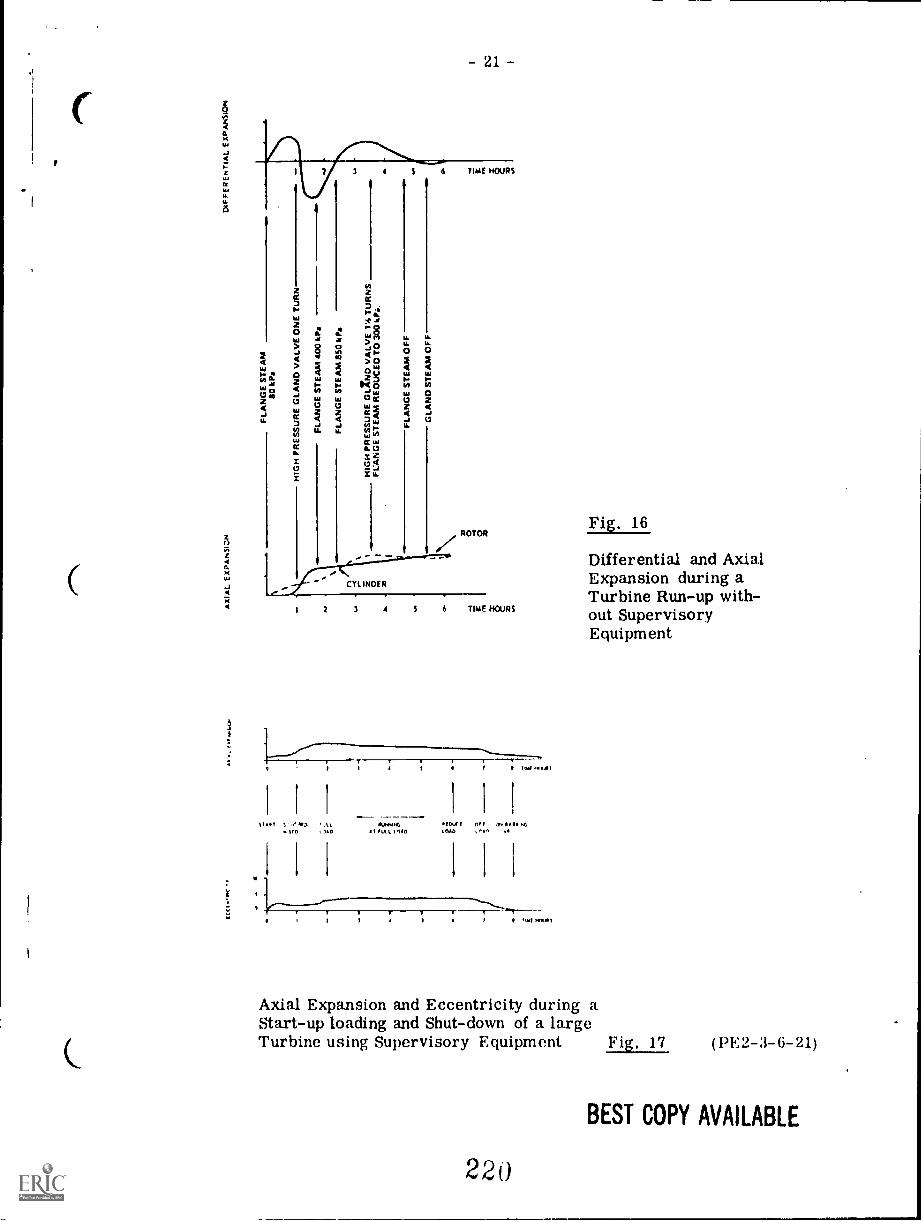
- 21 -
24
*a.sois
4LL
48
0
V.
CYLINDER
ROTOR
2 3 4 S 6 TIME HOURS
SI .1 'AL w.wiw MK, on 7.-1 /0 I Up .1 'at 010 tea(' o$,
$
lust ml..11
Fig. 16
Differential and AxialExpansion during aTurbine Run-up with-out SupervisoryEquipment
Axial Expansion and Eccentricity during aStart-up loading and Shut-down of a largeTurbine using Supervisory Equipment Fig. 17 (13E2-3-6-21)
2 20
BEST COPY AVAILABLE

- 22 -
Turbine Controls
In the previous pages, the operation and use of the kind of instrumentsassociated with measurements required on a turbo-generator, has been de-scribed. As an illustration of the uses of the various instruments, a typicalturbine instrument scheme is described below.
Typical Turbine Control Panelfor 60 MW set, 6200 kPa gage, 480°C type
(1) OutputAn induction pattern wattmeter is connected in series with one of thetariff meters to indicate instantaneous load, MW.
(2) PressuresPressure gages are used to show:
Steam pressure before and after throttleSteam pressure after first wheel (Curtis stage)Gland steam leak-offAll bled steam pressures (above atmospheric)Pressure to deaeratorHigh-pressure turbine exhaustBearing oil pressureRelay oil pressure for operation of governing mechanism.
(3) Vacuum and Low PressureKenotometer instrument for condenser absolute pressure.Sub-atmospheric pressures are given by diaphragm gages.
(1) Levels and PositionsThe levels of water (condensate) in the reserve tank and deaeratorvessel, are transmitted electrically to deflectional instruments.Positions of circulating water valves are sometimes shown onindicating instruments on the turbine panel since it is necessaryto adjust them to obtain optimum vacuum, depending on circulatingwater temperature.
(5) TemperaturesTurbine Stop Valve (r.s.v.) steam and the final feedwater usuallyhave separate large dial instruments. Recording instruments aresometimes used for T.S.V. temperature. Other temperatures onthe turbo-generator set are given on two multipoint instruments.
(11E2 -3-(; -22)
22.1

- 23 -
(6) Condensate PurityIt is usual to provide an indicating instrument supplied from the "Dionic"
meter. Dissolved oxygen meters and hydrogen ion concentration metersare usually mounted separately elsewhere.
(7) Supervisory PanelThis is sometimes incorporated into the turbine control panel; some-
timec it is a separate unit. Its instruments were described in previouspages.
(8) Indicators and AlarmsWhile these are not classified as instruments, it should be mentioned
that the malfunctioning of parts of the plant is usually shown up on illu-minated indicator panels, for example, excessive exhaust temperature,high bearing temperature, low oil level in reservoir, high water in high-pressure heater, high and low water in storage vessels, high-water levelin condenser, high conductivity in condensate, low-hydrogen purity ingenerator and loss of seal oil supply.
Fig. 18 is a photograph which illustrates a typical 6200 kPa gage,480°C rtombined boiler-turbo-generator gage board. This layout is efficientand compact.
Turbine panels are on the left-hand side of the operator. Pressure gagesand position indicators are at the top. In the middle, from the left to right,may be seen the two multipoint temperature instruments side-by-side, thewater purity meter, eccentricity records, and the Kenotometer, with verticalscale on its right-hand side.
On the extreme left of the panel are operating handles for motor-operatedvalves and pumps. On the console itself are further operating mechanismsfor controlling auxiliary plant. Governor and generator voltage are control-led from a central control room.

Q1 11LIE]=,
= V4 rio in 06' 6-70 ili4WW39
I _A. tat_ rjill 0 0 0 : Aim xa
ba
(A
i
...4.
k_
a
7'0 (NV ,----....._
,,l (rii, U ",,",,,I...' W l'
1::,,
c, r 7 ' IL, i ,V k_ . ....-
'."--:----"',.>
JA((((((ltt
owe!, '4_111P
1111110._400.
IMP
I
11.11111
14)
,11104,
')d »1
I

- 25 -
Turbine Automatic Control Equipment
The turbine instrumentation discussed in earlier pages indicated and recordedthe variations in certain temperatures, pressures, bearing vibrations, etc.
If now mechanical drives were fitted to the steam valves, drains, etc.normally manually-operated during a turbine run-up, and the turbine supervisoryinstruments arranged to monitor conditions, a program could be set up toautomatically start and run up a turbo-alternator set.
The following pages will describe such a system of turbine control developedby Associated Electrical Industries Ltd. (AEI), and given the name ACTRUSfrom the description, Automatically Controlled Turbine Run-up System.
Turbine Run-ups
Turbine run-ups are divided broadly into two types, cold and hot. Coldstarts occur after prolonged periods of shut-down, such as annual overhauls.Hot starts usually apply to the run-ups following an all-night or week-end shut-down, when the turbine metal will have retained a large part of its heat content.
The main effect of this retained heat on starting, is that the differentialtemperature between the turbine metal and the incoming steam is reduced,thereby permitting the use of higher steam temperatures and pressures witha resulting quicker run-up. Programmes as short as a few minutes areenvisaged for hot starts, while those for cold starts, on the other hand, maytake up to several hours.
For cold starts the usual form of programme is:
(1) A run-up fr.= barring speed - about 40 rev/min - to 1200 rev/minat an intermediate rate of acceleration.
(2) A "soaking" period in which the speed increases slowly from1200 rev/min to'1700 rev/min.
(3) A final run-up to 3600 rev/min at a high rate of acceleration.
The purpose of the soaking period is to warm up the turbine metal and reducedifferential temperature to a minimum before proceeding to full speed. Forreasons already mentioned, the soaking period can be omitted for a hot startand this, together with a faster rate in the early part of the run-up, results ina considerably shorter programme.
(PE2-3-6-25)
224

- 26 -
Under normal conditions the pre-set programme is followed without inter-ruption. But should abnormal conditions arise, the programme may have tobe interrupted or even reversed. This may be done either manually or bymeans of the automatic supervisory equipment built into ACTRUS and opera-ting on signals derived, for example, from turbine vibration, eccentricity ofthe rc tor, or differential temperatures. Should any one of the supervisorysignals exceed a certain limit the programme is interrupted and the turbinespeed is held steady. This situation is known as 'HOLD'.
If the supervisory signal continues to rise to a second limit, the programmeis reversed and the by-pass valves are made to close by reversing the motoroperating gear. This second situation is known as 'RUN-DOWN'.
In cases of greater emergency (i. e, over-riding signals from eccentricityor vibration detectors) the by-pass (and governor) valves are tripped byreleasing relay oil to drain. A more detailed description of these conditions,and certain limitations thereto, is given 'n a later section headed 'AutomaticSupervisory Equipment'.
Fig. 21 shows the equipment diagrammatically. Note that it is dividedinto three sections: Speed Control, Programme, and Supervisory Equipment.
Briefly the Programme unit sets the rate of increase of turbine speedduring the run-up. The Speed control opens the steam valves. The AutomaticSupervisory equipment monitors the conditions obtaining in the turbine andwill interrupt the programme in the event of abnormal conditions, such asexcessive vibration, differential expansion, etc. The following pages describeeach section in turn.
Pre-selimits
Run, Adiustable rate settingsI
II. owe mom ims unInpew ume mo erm mil lem mis imm el%1
I motor ltiM
sSutezDownProgramme % r
I .0"lis
,4,
Releienc
limmoniSpeed
Magnetic (Servo r moo.,./ T t .. LInvar amplifier' motor.........,' \,...... .
0.1000ea.dor I speed 4 error
rev/minDiflerential
(! ).. umeduaI
preSsura.
-.......0 4
1000-1100rev/m.in
I r i.
1100:3000 I 1' tubule speed Condenserrev/milla
Automaticsupervisoryequipment
Gearbox
Turbine
Turbmeinletvalve
Lan')generator
Programme unit Speed control servo
Fig. 21
225

- 27 -
Pro anuAne Unit
The object of the programme unit is to produce a reference voltage which,during run-up increases at pre-set rates from zero to a value representing fullturbine speed. This reference voltage is derived from a "Linvar" rotary indu-ctive device giving an output proportional to its angle of rotation over the range0-80°.
The rotor of the Linvar is driven by one of three constant speeds motors, eachhaving an adjustable gear ratio. A cam, geared to the linvar drive shaft, selectsthe three speed ratios in turn, the change-overs being made at 1200 rev/min and1700 rev/min. The Linvar is therefore driven at the first pre-set speed for tur-bine speeds up to 120 rev/min, at the second speed for turbine speeds from 1200 -1700 rev/min and at the third speed for turbine speeds from 1700 - 3600 rev/min.
The pre-set speeds are manually-set before start-up depending on turbine con-ditions - in particular the metal temperature of the high-pressure cylinder. Whenthe metal temperature is high, as it would be after an overnight shut-down, theslow soaking period provided by the second speed ratio is not required and theprogramme unit can be set to change over directly from the first ratio to the thirdat a turbine speed of 1200 rev/min. In this way the voltage from the Linvar risesfrom zero to a maximum and the speed control servo causes the turbine speed toincrease in a similar way.
Fig. 22 shows an illustration of the unit.
Run.u, fnolOtS notary Urn Rea.down eftolot linvatMI/

28 -
Speed Control Servo
Referring to Fig. 23, the turbine speed is caused to follow the desiredprogramme by servo control of the combined stop and emergency by-pass valves.An a-c tack- generator, driven by the turbine, produces a voltage output propor-tional to turbine speed. The difference between this voltage and the referencevoltage (known as the speed error) passes through a magnetic amplifier and isthen used to control the speed and direction of the servo motors.
If the turbine speed is too high the valves are driven in a closing direc-tion to reduce the flow of steam into the turbine; when the turbine speed is toolow the valve openings are increased to produce acceleration. This control,therefore, constitutes a closed-loop or servo system, turbine speed beingcontrolled by valve opening which is itself controlled by turbine speed-acting sothat the speed error always tends to zero.
In order to ensure that the rate of opening of the two by-pass valves isequal, their positions are measured by synchro elements and a balancing dif-ferential signal is fed back to the amplifiers in the servo control unit. Wherethe steam connections to the combined stop and emergency by-pass valves arecommoned on both sides of the valves it is possible to run-up by opening onevalve only. In this case it is usual for both valves to be fitted with servo equip-ment, but ACTRUS controls only one of them during the course of run-up.Equal wear of the valves can be achieved by dividing the run-up between themduring the lifetime of the set,
Due to the inertia of the turbine and alternator rotors, the speed willchange rather slowly and the control described would be relatively under-damped. To overcome this an additional voltage proportional to the pressuredrop through the turbine is generated in a pressure transducer and fed backinto the magnetic amplifier. Due to rapid response of pressure to valve open-ing, this feed-back produces a well damped control.
If conditions in the turbine required that a 'HOLD' should be made in theprogramme, the drive to the 'Linvar' is interrupted. The speed reference isthus held constant and consequently no increase in turbine speed is permitteduntil the programme is restarted.
Where conditions in the turbine are more critical, a 'RUN-DOWN' maybe necessary. In. this case the programme is interrupted as before, but heretwo additional actions occur. In the first place the speed control servo receivesa bias signal which causes the steam valves to close at the full rate of the servomotors. The set then slows down at a rate dependent upon its own inertia andthe friction forces operating. As this takes place an additional motor in theprogramme unit is energised and controlled by the speed error signal in such amanner that the reference signal is at all times proportional to the turbinespeed. Thus, when run-up is re-initiated, the turbine and reference speeds arealready equal and normal run-up can proceed,
(1)1.:2-3-(; -28)
22 7
I
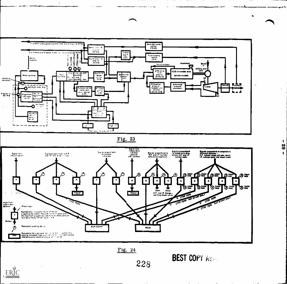
Ne.{NII
P
.At 55000 11.1 t la
1101111t 1' 11 Wed .. bo 1,S1 '4
.4 4 P ,, ...0 udouilli,
, UP0
1 Cii N..le '1 WO. 00A.
1 t,
80.01 15.5 Atwo. ttl 0
is
t
1'101
1
:v,:o.1- 5 .(01,- ,.;5.4- VI 1.0(0 00.r
1.045115't..ti 045
Fig, 23
sit....OfdloItiOAil1C101
P. condul
Appmairmmilp$90 gig r04 te.e=51045114.P. w LP
elbow .4111
11,090114,1111 ItP lad I P 10004.,
10111tIvotel Mans.**
INS* 100101410111 M 101101111,11111111111/0
KO. 5n11tNM IsopptcINPOr 1110111 4.4 reheat IOWA
Chm Cies IHP 04IP luny_gernins 11.5111 151111
01
vo
111.0.14All 001,00 410,0 II5 1'105111 Ins mslo 1.5 0.. 4e.50,5 41.5 0.0..5 140 P.4./1 00,0 e U. 5011 115
1001 15.50.0 0. 0 i it
MI 1012 45..1
Asp $$$$$ 04 . .0 .0.441.515 1105 v.
0
-0 / ^54 1..s 1.4itAtqlAtf 4.101 ri..5 11^0 10 j. 0 0
Itorkss,Fig. 24
228BEST COPY
.

- 30 -
Automatic Supervisory Equipment
Detectors fitted on the turbine ensure constant supervision of vibration, rotoreccentricity, differential temperatures, condenser vacuum, etc. The outputsfrom these devices are fed to the turbovisory equipment mounted in a separatecubicle alongside ACTRUS. This operates various recorders and indicatorswhenever the turbine is running. During run-up the turbovisory signals are alsofed into comparators (A), Fig. 24 on the previous page, where they are comparedwith references which may be pre-set by means of setting devices (B). Thesecomparators are actually sensitive moving-coil relays with adjustable contactsfor use as reference values, which are finally fixed during commissioning to suitthe particular set concerned.
When the incoming signal exceeds the reference (that is, when the limits areexceeded), the comparators initiate self-sealing relays which pass on the signalto the master hold or run-down gate. This, in turn, sends the appropriate con-trol signal to the speed control unit and, in the case of differential expansion, italso initiates operation of the H-p and I-p flange-warming valves. As the self-sealing relays will only reset when the supervisory signal has dropped by about10%, the possibility of indefinite action around the set point is eliminated.
To give a typical example: if pedestal vibration exceeds a pre-set amplitude,a HOLD is applied to the programme by stopping the programme drive motor.When the vibration again comes within limits, the programme is resumed. Ifthe vibration should exceed a second limit, the steam valve is closed causing theturbine speed to fall. At the same time a run-down motor in the programme unitdrives the Linvar so that its output is always matched to that of the turbinetachometer. Conditions are then correct for resuming the run-up programmewhen the vibration has dropped to an acceptable value.
(PE2-3-6-30)
229

QUESTION SHEET
POWER ENGINEERINGSecond ClassSect. 3, Lect. 6
1. Comment upon the precautions which should be taken beforestarting a new steam turbine for the first time after completionof erection.
2. Briefly describe the steps to be taken when running up a centralstation turbo-alternator.
3. What faults can cause loss of vacuum in a steam turbine condenser ?How would you discover and correct the ?
4. Sketch and describe an instrument used fo. easuring the absolutepressure in a turbine condenser.
5. Why measure absolute pressure rather than vacuum, in a turbinecondenser ?
6. What is meant by blade fouling? How can this be prevented?
7. Distinguish between blade fouling and blade erosion.What precautions can be taken to avoid the latter ?
8. What is Turbine Supervisory equipment?What measurements does it make?
9. Explain how a turbine shaft vibration and expansion can be measuredand recorded and how this information is put to use during the turbineoperation.
10. Give a brief outline of the operation of a fully-automated controlsystem used for running a turbo-alternator up to speed, ready forloading.
(PE2-3-6-Q)
230

1111111=MIlW
11111loMp.
IrDrilt=f1aJ. uminna ybmn.1
8.5
GAS TURBINES
Goal. Performance Indicators:
The apprentice will be able todescribe gas turbines and their
operation)
1
1. Describe types of gas turbinesystems.
2. Describe fudctions of regenera-tors, intercoolers and reheaters.
3. Describe components of a gas
turbine system.

.=1MIMMINION. MEM.INSTRUCTIONAL L AHNINL YS I hMb
'Study Guide
Read the goal and performance indicators to find what is to be learned frompackage.
Read the vocabulary list to find new words that will be used in package.
Read the introduction and information sheets.
Complete the job sheet.
Complete selfassessment.
Complete postassessment.
2
232
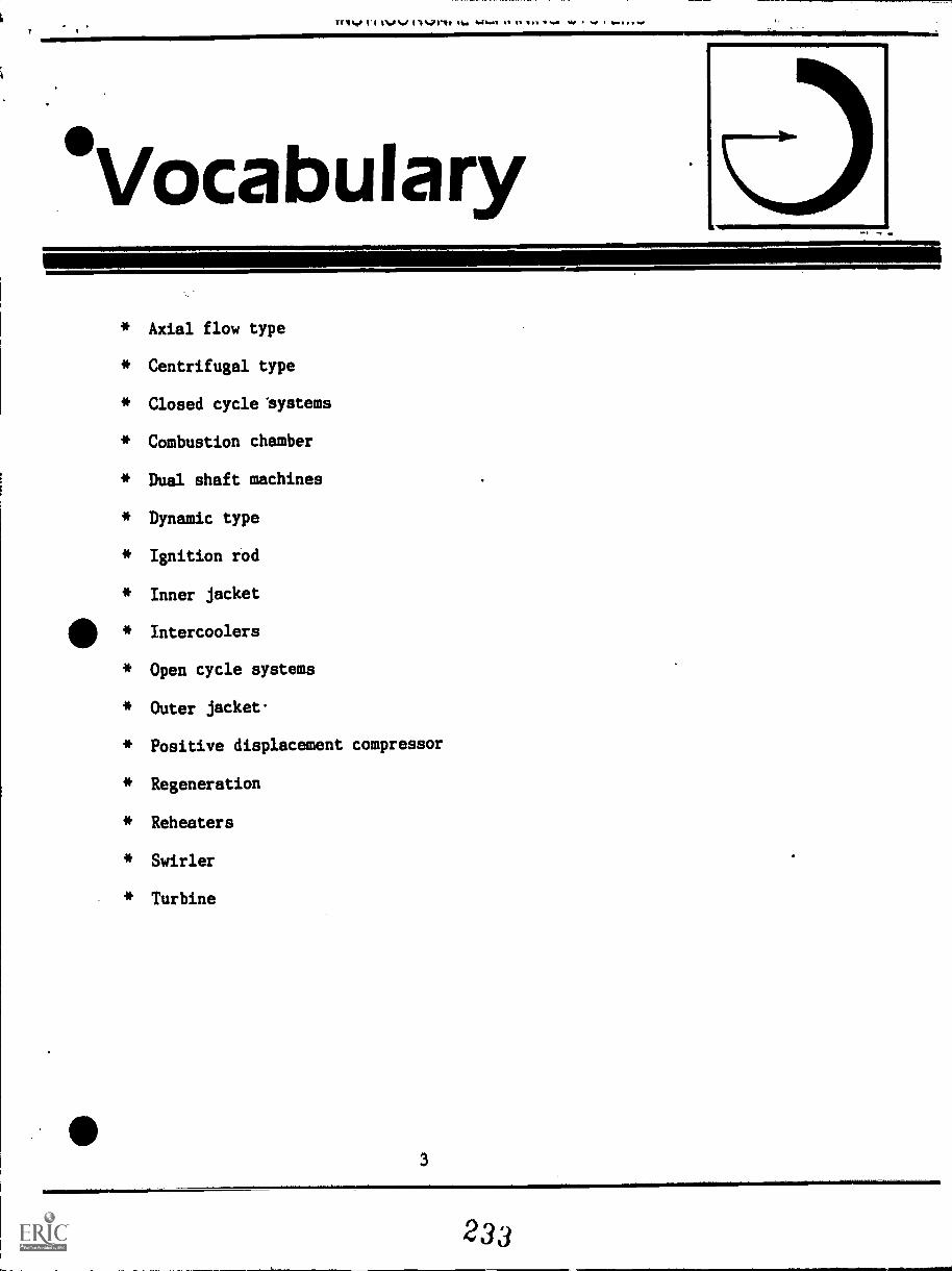
l'Etv 1)%of 44g 4.141 el II lo v Na .4,
°Vocabulary
* Axial flow type
* Centrifugal type
* Closed cycle 'systems
* Combustion chamber
* Dual shaft machines
Dynamic type
Ignition rod
Inner jacket
Intercoolers
* Open cycle systems
* Outer jacket.
Positive displacement compressor
* Regeneration
Reheaters
* Swirler
* Turbine

INS 1 Mk; I IUNAL, LtiktiNINLI J I I MI*
ntroductionPower plants are sometimes located in areas where steam turbines are not feasibleor the purpose of the plant does not justify a steam powered operation. Gasdriven turbines are often more suitable in those cases.
A gas turbine operation has certain characteristics that make them suitable insome cases. They offer a simple plant layout with low installation costs. Thegas turbine requires a lighter foundation than a steam plant and a much smallerlocation area. These characteristics make them suitable for electricitygeneration up to 30 megawatts of output. Gas turbinec find wide usage inaircraft, oil pipeline stations and operation of ships and. railroads.
4
234

INSTRUCTIONAL LEARNING SYSTEMS
InformationThe gas turbine operates by passing compressed, hot air through the blades of aturbine: The air compressor requires about 2/3 of the energy produced by theturbine. The compressed air enters the turbine at some 700 C. Higher
temperatures increase the efficiency of the turbine but excessive heat will
damage the blades.
TYPES OF GAS TURBINES
Open Cycle Systems
A gas turbine plant is composed of a compressor, combustion chamber and a
turbine. Open cycle systems pull inlet air from the atmosphere and dump exhaustair back into the atmosphere. Some units have heat exchangers that save the
exhaust heat and use it at the inlet. The process of saving exhaust heat is
411termed regeneration. A simple open cycle gas turbine plant is shown in the
followl.ng diagram.
Air Exhaust
om ustionChamber
5
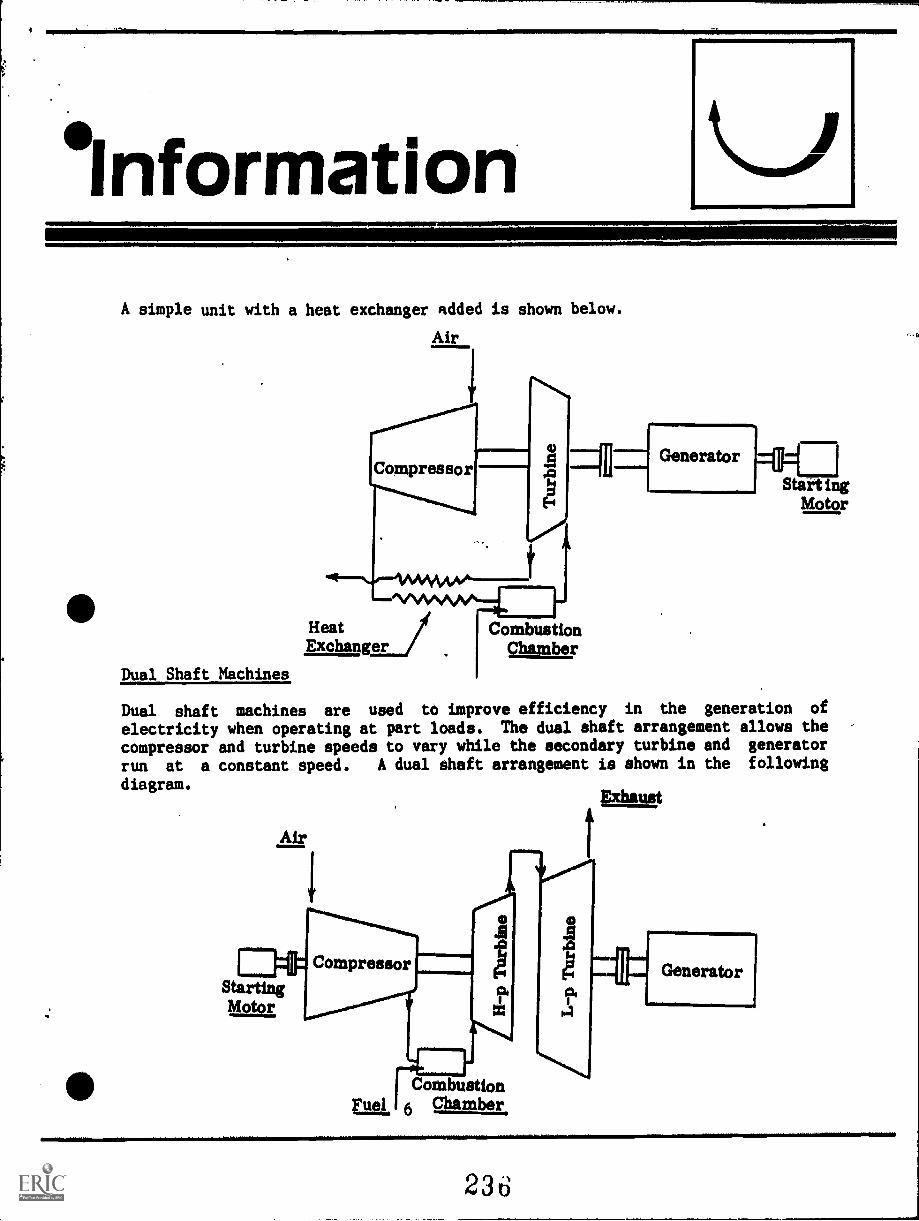
'InformationA simple unit with a heat exchanger added is shown below.
Air
Dual Shaft Machines
Dual shaft machines are used to improve efficiency in the generation of
electricity when operating at part loads. The dual shaft arrangement allows the
compressor and turbine speeds to vary while the secondary turbine and generator
run at a constant speed. A dual shaft arrangement is shown in the following
diagram.Diummit
CombustionChamber
Air
EatStartingMgkr
Compressor
CombustionFue 6 Chamber
Generator
236

0111MMOMMINillPINP.
INSTRUCTIONAL LEARNING SYSTEMS
InformationRegenerators, Intercoolers and Reheaters
The efficiency of a turbine can be increased by the use of a regenerator to
capture the thermal valve of the exhaust gas and return it to the inlet air at
th combustion chamber. Another efficiency improvement can be made by
intercooling the air during compression. This process reduces the work to the
compressor. If the air is reheated during its expansion within the turbine, the
output of the turbine can be increased. Intercoolers and reheaters are devices
used to improve the efficiency of gas turbines. The diagram.below shows the
arrangement of regenerators, intercoolers and reheaters in a dual shaft turbine.
Exhaust
to Stack
Regenerator
H-pCompressor
CombustionChamber
L-pCompressor
Air DIAGRAMMATIC LAYOUT
7
L-pTurbine
Fuel, NI.ombustionChamber
H-pTurbine
11111
NOMMIN1041/Generator

INSTRUCTIONAL LEARNING SYSTEMS
InformationClosed Cycle Systems
An open cycle system pulls its air from the atmosphere and dumps it back as
exhaust. A closed cycle system circulates the air through its system
continuously. 'Air heaters are required for heating the air that enters the
turbine. Coolers are used to cool the air before it enters the compressor. The
air heater is the major drawback to the use of closed cycle plants. A diagram
of a closed cycle system is shown below.
CoolerV
Compressor
Generator
411
Regenerato"4'Heat
AirBoiler
GAS TURBINE COMPONENTS
Compressors
1:-.1StartingMotor
Positive d pull in air and compress it before releasing
it to the turbine. Some type of reciprocating piston or rotary device is used
to compress the air. Several types of positive displacement compressors are
used in gas turbine operations.
8
238

INSTRUCTIONAL LEARNING SYSTEMS
nformation1. Reci:rocating type2. Lobe type3. Vane type
A dynamic type' compressor uses rotating blades to squeeze the air into a
compressed state. Two types of dynamic compressors are used in gas turbine
operation.
1. Centrifugal type2. Axial flow type
The lobe type compressor is common to gas turbine applications because it can bebuilt in large sizes and with maximum efficiencies.
Combustion Chambers
The combustion chamber heats the air
between the compressor and turbine.
Remember that the air is cooled beforeentering the compressor and heated beforeentering the turbine. At the top of thecombustion chamber is a swirler and
ignition rod. As the air enters nearthe bottom of the chamber, it moves upwardbetween an inner jacket and an outer jacket.As it moves upward, the air mixes withcombustion gases. At the top, part ofthe air is mixed with fuel by the swirler-and is.used in the combustion process.The hot gas leaves the combustion chamberand moves into the turbine. Ignitionrods are used to light the combustion
chamber. The following diagram showsparts of a combustion chamber.
9
Fuel
Inlet
.7Swirler
Ignition
Imp, _Rod
Outer 94Jacket*-
Hot
GasOutlet
Inner
,Jacket
AirInlet
239

INSTRUCTIONAL LEARNING SYSTEMS
InformationTurbines
The major difference between gas and steam turbines are in the blading. Blade
spacing is greater in the gas turbine because air flow requires fewer stages
than steam. Gas turbine blades are subjected to higher temperatures and must be
constructed of heat resistance metals. A typical gas turbine and its components
are shown below.
Single Boanng Generator
Main Lubrication Oil Pump Impeller
Aumbay
Artoi Air Comp,SSW
Gas Turbine- GeneratorA., :W
Doueie helical R.Cluctforo ;eon
i Solid Couoting to Reduction 3eo
Compressor Inlet Eno esor.n9
Combustion Chamoe
%mine Eanaust End Bearing
10
240

INSTRUOTIONAL LEARNING SYSTEMS
Assignment
* Complete job sheet.
Read pages 22 - 34 and 41 - 42 in supplementary reference.
* Complete selfassessment and check answers.
Complete post-assessment and ask instructor to check answers.
11

INSTRUCTIONAL LEARNING SYSTEMS
°Job SheetINSPECT A GAS TURBINE PLANT
Locate a gas turbine plant in the community.
Ask permission to observe the unit.
Identify the following: .
- Manufacturer of compressor and turbineSingle or dual shaft
- Does it have a heat exchange (regenerator)?- Does it have an intercooler?- Does it have a reheater?- Location of generator- Type of compressor
Location of combustion chamber
Ask questions of operator until you fully understand the parts and function
of the gas turbine equipment.
* 'Observe start-up and stopping procedures if possible.
fit
12

INSTRUCTIONAL LEARNING SYSTEMS
SelfAssessment
Match the following terms and phrases.
1. Regeneration A. Temperature of air entering agas turbine.
2. Positive displacement compresser B. Saving exhaust heat for improvedthermal efficiency.
3. 700 C C. Intercools air during compression.
4. Lobe D. Reheats air during expansionwithin the turbine.
5. Swirler E. Continuous circulation of air
through system.
6. Closed cycle system F. Common type of compressor togas turbine applications.
7. Axial flow G. Uses rotating blade tocompress air.
8. Intercooler H. Uses reciprocating piston orrotary device to compress air.
9. Dynamic type compressor I. Mixes air and fuel in combustionchamber.
10. Reheater J. Type of dynamic compressor.
13
243

IS
INSTRUCTIONAL LEARNING SYSTEMS
Self AssessmentAnswers
B 1.
H 2.
A 3.
F 4.
I 5.
6.
7.
C 8.
G 9.
D 10.

1 INSTRUCTIONAL LEARNING SYSTEMS
*PostAssessment
1. An cycle turbine system takes inlet air from the
atmosphere and dumps exhaust air back into the atmosphere.
2. The process of saving exhaust heat is called
.3. Dual shaft machines improve efficiency of turbines when operating at
load.
4. Reheating of air during its expansion in the turbine can be accomplished by
the use of a
5. Cooling of air during compression is accomplished by the use of an
6. A cycle turbine system continuously circulates air
through its system without dumping exhaust into the atmosphere.
7. List three types of positive displacement compressors.
8. List two types of dynamic compressors.
9. rods are used to light the combustion chambers.
10. The mixes air with fuel at the top of the combustion
chamber.
15
.INS'114U61 IONA. LtAHNINLi SYS 1 CMS
InstructorPost AssessmentAnswers
1. Open
2. Regeneration
3. Part
4. Reheater
5. Intercooler
6. Closed
7. Reciprocating, lobe, vane
8. Axial flow, centrifugal
411 9. Ignition
10. Swirler
16
246

INSTRUCTIONAL LEARNIN1 *SYS I hAllb
SupplementaryReferences
* Correspondence Course. Lecture 8, Section 3, First Class.
Southern Alberta Institute of Technology. Calgary, Alberta, Canada.
17
SOUTHERN ALBERTA INSTITUTE OF' TECHNOLOGYCALGARY, ALBERTA
SECTION
PRIME MOVERS
Correspondence CoursesPower Engineering
GAS TURBINES
15.5
First ClassLecture 8
Gas turbines would be chosen as the prime movers for a power plantin cases where the location or purpose of the plant makes some or all oftheir characteristics particularly advantageous.
These characteristics are:Little or no water requirements;High power to mass ratio, and consequently only light
foundations needed;Rapid starting and loading ability with no stand-by losses
which makes them ideal for peak load purposes;Simple plant layout with very few auxiliaries, hence small
location area required;Low installation cost, and reduced operating labour require-
ments;Best efficiency and maximum output attained with low
ambient air temperatures.
as turbines are being used at the present time for electricitygenehtion in sizes up to about 30 megawatts, though generally the heatrate of a gas turbine will be higher than the heat rate of a steam turbo-generator set of equivalent power.
They are, of course, extensively used for aircraft propulsion wherethey have many advantages over the reciprocating engine such as use oflower grade fuels, less fire hazard, better balance, greater power tomass ratio, simpler cooling problems, etc.
They are also employed in industrial processes, such as iron andsteel production where they are used for blast furnace blowers (in thiscase the gas turbine uses blast furnace gas as fuel); in oil refineriesusing the Houdry oil cracking process, and in oil pipeline pumping units.They are also used for the propulsion of ships and railway locomotives,and in smaller sizes supplied with exhaust gas and used to drive centrifugalblowers for supercharging internal combustion engines.
24

Principles of Operation
The principle of the gas turbine was first proposed during the 18th centurybut its practical application has only been developed in recent years. This hasbeen dependent on the development of efficient compressors and the perfecting ofsuitable materials to withstand the high temperatures used in the turbine blading.
The gas turbine derives its power from the expansion of a working fluidthrough the blading of a turbine in a similar manner to the expansion of steamthrough a steam turbine and uses the same principles of impulse and reaction.
It is interesting to note in this connection that the maximum compressionratio in a gas turbine plant will be about 7 : 1 and this is the pressure ratio whichis available to the turbine. A steam turbine plant however may have a pressure of17500 kPa at the turbine stop valve and 3.5 kPa at the exhaust, which represents apressure ratio of 5000 : 1.
Gas turbine speeds of rotation vary quite considerably with the size of themachine, for example, a large machine of 30,000 kW may run at 3,600 rev/min,an 6000 kW machine at about 5,000 rev/min, a 4000 kW unit at about 6,000 to7,000 rev/min, and 750 kW machines from about 10,000 to 20,000 rev/min.
The gross thermal efficiency of simple cycle gas turbines ranges from 17 to22%.
The working fluid can be any hot gas, but is most often air which has beencompressed and then heated in a combustion chamber. The gas turbine drives itsown air compressor, the power absorbed by the compressor being about 2/3 of thetotal turbine power output.
Mention was made in Lecture 1 of the Brayton Cycle, used as the basis ofoperation of a gas turbine. It was shown that for any given compressor inlet air,and turbine inlet gas temperatures, there is an optimum compressor pressureratio at which maximum work output would be achieved by the gas turbine, togetherwith the best practical efficiency.
Once the machine has been designed, the compressor pressure ratio isfixed and the variables remaining which affect the machine efficiency and output arethe compressor inlet air temperature, the turbine inlet temperature and the massgas flow.
The compressor inlet air temperature, in the case of open cycle gas turbines,is dependent only on the atmospheric air temperature; the lower this is, the higherwill he the gas turbine efficiency and output.
PEI -3-8-2
24
For example, a Brown-Boveri machine rated at 20 MW output and a. heatrate of 15,350 kJ/kWh with ambient air temperature of 70°C is quoted as delivering30 MW at 12,630 kJ/kWh when the air temperature drops to -400.
The temperature of the gas at the turbine inlet can be controlled by variationof the quantity of fuel burned. Maximum load and maximum efficiency will beobtained with top inlet temperature.
The turbine inlet gas temperature is limited by the material of the turbineblades and is generally not more than 650°C to 700°C for power plant gas turbines.Aircraft engines are designed for a shorter operating life and the inlet gas tempera-ture used in this case is approximately 870°C.
Efforts are being'made by designers to enable gas turbine blades to withstandhigher gas temperatures through the use of some form of blade cooling. Most ofthe suggested designs employ the circulation of a coolant through the blades such aswater vapourizing to steam, or forced air, or some liquid sealed within the bladesrejecting its heat by circulation to another fluid in the turbine wheel.
If the gas inlet temperature could be raised to 950°C, gas turbine thermalefficiencies would advance to the 309; range. The mass gas flow cannot be variedindependently in the open cycle gas turbine plant and is a function only of thecompressor speed; load variations in this type of plant are carried out by controlof the turbine inlet temperature through the quantity of fuel burned. The closedcycle gas turbine design however, does allow control of the mass gas flow throughthe machine and this is used together with turbine inlet temperature as the methodof load control.
The energy available to the turbine for production of work depends upon theheat content of the gases per kg and the mass of gas flowing; the calculation ofavailable power is carried out in a somewhat similar manner to that for thesteam turbine.
A typical power calculation will be found at the end of this lecture.
The fuel used in gas turbines up to the present day, has been restricted tooil or gas. Many experiments have been carried out, using coal as fuel, buttroubles due to slagging and erosion of the turbine blades have yet to be overcome.
2 50
1)}:1

PLANT ARRANGEMENTS
Open Cycle Systems
The simple gas turbine plant consists of a compressor, a combustion chamberand a turbine. Fig. 1 shows a diagrammatic layout.
Atmospheric air is compressed and then heated to the maximum cycle tem-perature by the burning of fuel in the combustion chamber. The resulting productsof combustion expand through a turbine and exhaust to atmosphere. The turbinedrives the compressor and the balance of power is available to drive the generator.A starting motor is required to get the system into operation. Fig. 2 is a descrip-tive sketch of the plant.
Regeneration
The exhaust gas temperature from the simple gas turbine will be very high.The thermal efficiency can be appreciably improved by.the addition of a heat ex-changer to transfer some of this heat in the exhaust gases to the air prior to itsentry to the combustion chamber. This is termed regeneration. Fig. 3 showsthis arrangement diagrammatically.
The optimum sized regenerator recovers about 75% of the exhaust heat inthe gas which is available above the compressed air temperature. The use of aregenerator will make typical reductions in the exhaust gas temperature from 450to 260 °C while increasing the compressed air temperature from 230°C to 400°C.
Fig. 4 is a descriptive sketch of the plant showing the addition of the heatexchanger. The use of a heat exchanger or regenerator in a gas turbine meansthat a large area of heat transfer surface has to be supplied. The physical bulk ofa regenerator can be accommodated in a stationary power plant but is impracticalfor aircraft or locomotive engines.
In Lecture 1 of this Section, the ideal Brayton cycle was described and Fig.23 was drawn to represent this cycle on a TO diagram. Fig. 5 herein is a similardiagram. If the gases are passed out to waste at point 4 (the turbine exhaust) therejected heat will be that shown by the shaded area under 4 - 1. If a regeneratoris tied to recover some of this waste heat then the air temperature can be raisedafter leaving the compressor to a figure approaching that of the turbine exhaust gas.
Fig. 6 illustrates the principle. The area under 4 - 4' represents heat givento the regenerator and used to raise the temperature to 2'. The heat rejected toexhaust is now only that represented by the shaded area under 4' - 1.
This makes a considerable improvement in the gas turbine thermal efficiency.For example, a simple gas turbine with reasonable component efficiencies, com-pressor 847 , turbine 86%, combustion 97% and a gas temperature of 650°C, butwithout a heat exchanger will have a thermal efficiency of the order of 20%. If aheat exchanger of 75% effectiveness is added this will be raised to about 25% (75%effectiveness meaning, able to transfer to the air 75% of the heat available in theexhaust gas).
PE1-3-8-4
251

CombustionChamber
- 5 -
Air Exhaust
Fuel j
ICombustion
Chamber
StartingMotor
DIAGRAMMATIC LAYOUT
Eigd
AirCompressor
iiiExhausts Air
Generator
-DESCRIPTIVE SKETCH-Fig.2
SIMPLE OPEN CYCLE GAS TURBINE PLANT
252
PE 1 -3-8-5

6
Air
Compressor
Heat CombustionExchanger Chamber
Combustion Chamber
Generator AziStarting
Motor
-DIAGRAMMATIC SKETCH-
ER]
Heat Exchanger
Generator StartingMotor
-DESCRIPTIVE SKETCH-
Ei g
PE1 -3-8-6
OPEN CYCLE
GAS TURBINE with REGENERATOR
253

T
5
7
1
To Diagram for Brayton Cycle
Attractive as these gains appear, many industrial gas turbine plants inoperation today de not include regenerators, for the reason that the plants aredesigned essentially to supply peak load demands. They are intended to be runfor short periods only and are most attractive in their simplest form and withthe minimum cost of construction and installation. The heat exchanger orregenerator is necessarily a large and expensive item of plant equipment sincethe pressure losses in both air and gas flows must be kept to a minimum.
Dual Shaft Machines
The single shaft gas turbine is essentially a constant speed machine,variations in speed causing considerable changes in the power output. Forexample. with the turbine inlet temperature kept constant at its top figure a 10%reduction in turbine speed will reduce the power output by about 25%, and a 25%reduction in speed makes about 60% reduction in the power output.
When the shaft is separated as shown in Fig. 7, the unit becomes a dualshaft machine.
When used with a gas turbine plant for electricity generation this arrange-ment gives better efficiency at part loads by allowing the speed of the compres-sor and primary turbine to vary, while the secondary turbine and generatorremain running at synchronous speed. It also reduces the power required forthe starting motor as this does not now drive the secondary turbine and genera-tor.
It can be adopted for gas turbines used for mechanical drive in whichcase it can give variable speed operation of the power turbine take-off and itsdriven machinery.
PF.1 -3-8-7

lc
Compressor
Air
OltStartingMotor
Compressor
Exhaust
Generator
CombustionFuel. Chamber
OPEN CYCLE GAS TURBINE with DUAL SHAFT
Exhaustto Stack
H-pCompressor
I 1 I q I
Regenerator
.1Combustion
Chamber
Fuel
Intercooler Fuel
Water
all
Air DIAGRAMMATIC LAYOUT
L-pTurbine
H-pTurbine
om ustionChamber
Generator
OPEN CYCLE GAS TURBINE with REGENERATOR,1NTERCOOLER
:; and REHEATER Fig.8
255

9
Interco() ling and Reheating
Further improvements in the gas turbine efficiency and output can beobtained if the air can be intercooled during compression and the gas can bereheated at some stage in its expansion through the turbine.
Fig. 8 shows the arrangement with Regenerator (or heat exchanger),Intercooler and Reheater. Now the machine is in two-shaft form with twoseparate compressors and turbines and a second combustion chamber forreheating the gas between the two turbines.
Referring to the original PV diagram for the Brayton Cycle (Fig. 22, this Sect.Lecture 1 - repeated as Fig. 9 below): the cross-hatched area should be theamount of work available for the cycle. Compression 1 - 2 and expansion 3 - 4were each adiabatic operations. If these could have been carried out asisothermal (constant temperature) operations, the compression would be 1 - 2'and the expansion 3 - 4' . This would have increased the available work con-siderably.
Adiabatics
4'
IsothermalsVolume V
P-V Diagram for Brayton CycleFig. 9
An ipproximation can he made to this condition by intercooling the airat one or more stages in the compression and by reheating the gas at one ormore stages in the expansion. This is indicated on Fig. 10. The intercoolingreduces the work input to the compressor and the reheating increases the workoutput from the turbine. The net effect of the whole is to increase the outputof the gas turbine and also to increase its thermal efficiency.
For example, General Electric Co. quote a thermal efficiency of 29.1(1;,for a gas turbine of their design driving a 26 MW generator and operating on aregenerative, intercooled, reheat cycle.
PE 1 -8-9
256

- 10 -
Uses of Exhaust Heat
One of the largest sources of loss in the gas turbine plant is in the hightemperature exhaust gas. The temperature at the turbine exhaust may be 425°C.The use of a regenerator has been mentioned as one method of recovering some ofthis heat. A waste heat boiler producing steam for space heating or process workis sometimes used, either separately or in conjunction with a regenerator.
The fuel 1 Tiled in the combustion chamber of the gas turbine uses only asmall proportion of the total air flowing in the system for combustion (about 20%)so that the oxygen content of the final turbine exhaust gas may be about 17% asagainst 21% contained in atmospheric air by volume.
Further, the air quantities used by a gas turbine are considerable (about0.4 mYmin for each kW produced), so this turbine exhaust gas can be used asheated air for combustion in a steam boiler furnace. This combination of plantsgives an improved overall thermal efficiency.
A combined steam and gas turbine plant may also be achieved by dischargingthe compressed air from the gas turbine air compressor into the steam boilerfurnace and then expanding the hot exhaust gases from the boiler through the gasturbine. This method results in a supercharged boiler and if some of the gas tur-bine exhaust heat can be recovered in feed heaters, it will give a greater increasein overall thermal efficiency than the first mentioned combination steam-gasturbine plant. A gross thermal efficiency of 42% has been obtained from this typeof combined steam-gas turbine plant.
Further. mention of combined steam-gas turbine plants will be found in thenext lecture.
Closed Cycle Systems
Note that all of the systems so far mentioned operate on an Open Cycle.That is, the air used is drawn from atmosphere and the exhaust from the turbineis rejected to atmosphere. Almost all of the gas turbine plants in use todayoperate on the Open Cycle system.
Gas turbines can also he constructed using a Closed Cycle, in which theworking medium (air) is circulated continuously through the system.
Fig. 11 shows a layout of the Closed Cycle.
PE 1 -3 -8 -1 0
257
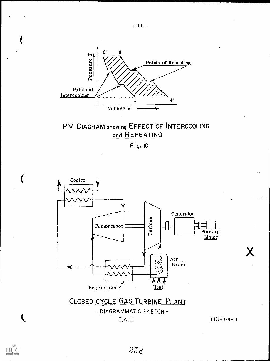
Points ofIntercoolin
3
Points of Reheating
Volume V
P-V DIAGRAM showing EFFECT OF INTERCOOLINGand REHEATING
Fig. 10
Cooler
Compressor s-
Generator
Regenerator/ Heat
Air13oiler
CLOSED CYCLE GAS TURBINE PLANT
-DIAGRAMMATIC SKETCH
Eig. L1
258
LIStarting
Motor
1'El -3-8-11

-12-
In this case the working air has to be heated in an Air Heater before entry tothe turbine and cooled before entry to the Compressor.
The closed cycle system has many advantages and is capable of full loadthermal efficiencies approaching 35%; part load efficiencies remain high also, beingup to 30% at 25% load. The added complications however tend to offset the advantagesby increasing the cost of installation and maintenance and there are very few plantsof this type in commercial operation today.
Since the working air is not drawn into the compressor from the atmosphere,the pressures throughout the system can be made much higher than in the open cycleplant. The turbine output depends upon the mass of gas flowing through it so thatthe increased air density results in a smaller machine for a given output rating.
Continuous recirculation of the working air with no addition of combustionproducts avoids fouling of turbine blades and heat transfer surfaces.
Use of an air heater instead of a direct combustion chamber allows theburning of fuels which would be unsuitable for the gas turbine blading.
Control of the plant output can be et acted by variation of the density of theworking air; this is done by increasing a decreasing the quantity of air in thesystem. By this means the speed and working temperatures can be kept constantduring load variations and high efficiencies can be maintained at part loads.
The open cycle plant must use air if fuel is to be burned in the combustionchamber; the closed cycle plant however, could be charged with any gas whichpossesses satisfactory operating characteristics. Hydrogen, Helium, or a mix-ture of Helium and CO2 have been suggested, the main advantage to be gained overair being the higher heat conductivity. This in turn reduces the necessary heattransfer surfaces required in the air heater, the regenerator and the cooler.
The chief disadvantage of the closed cycle system is the use of the air heaterwith its large bulk, inefficient heat transfer, cost alit, design difficulties, inComparison with the direct combustion chamber of the open cycle plant.
Fig. 12 shows a schematic diagram of a closed cycle gas turbine plant byMessrs. Escher Wyss, and Fig. 13 shows a semi-closed cycle plant developed byMessrs. Sulzer Bros. The semi-closed cycle uses direct combustion gases forthe work turbine and thus reduces the size of air heater required.
PE1 -3-8-12
259

( 442 (662 At 41
GOVERNOR
RESTORINGDEVICE.
686o
C.
2365 kPa16 t.635 kPa
PotC MOWEDINLET- OUTLET VALVE
BY-PASS VALVE
MR ACCUMULATORS
Li GENERATOR, 11, 12 INTERCOOLERS.
T, TURBINE. AIR HEATER.
C, 1,-p. COMPRESSOR. PR, PRECOOLER
C? 1-p. COMPRESSOR El -p. HIGH PRESSURE RECEIVER.
C COMPRESSOR L-P, LOW PRESSURE RECEIVER.
E. HEAT EXCHANGER
ATMOSPHERE
CLOSED CYCLE TURBINEFlg,I2
650°C1650 kPa
0 1,-p COMPRESSOR.
C2) INTERCOOLER
0 ii-p COMPRESSORNEAT EXCHANGER
COMBUSTION CHAMBER
0 COMPRESSOR TURBINE.
0 PRE COOLERTURBINE
9
WORN TURBINE
SUPPLYING
COMBu5TioN AIR,
IO STARTING MOTOR
SEW-CLOSED CYCLE TURBINEFig. 13
260
1)1.:1 -3 --13
BEST COPY AVAILABLE

Water Itljection to Gas Turbines
It was mentioned at the outset that in choosing a type of plant for the pro-duction of power, the engineer would be influenced by the reduced first cost,simple layout, suitability for load peak purposes, etc., of the gas turbine plant,despite its lower efficiency and higher fuel costs. It follows that he N (Add heinterested in any device which would increase the power output of the gas turbineeven at the expense of a reduced efficiency. Especially if this need he usedonly at peak load periods.
By injecting water into the hot gases before they enter th.! turbine, to gasturbine output can be increased by about Mr( at the expense of about 25c; increasein the heat rate. When this is done the water must not contain more than 1ppm ofimpurities if turbine blade deposits are to be avoided,
The effect of this water injection is that the water is evaporated into steamwhich has the effect of increasing the density of the working gas in the turbineand hence increasing the turbine output. This is done without any increase re-quired in the work input to the compressor.
The steam leaves the turbine exhaust at high enthalpy however, and thiscauses the reduction in plant efficiency.
Similar results can be achieved by injecting steam into the working gas orIcy allowing the hot :lir leaving the compressor to evaporate water and carry thewater vapour N1 ith it into the regenerator, combustion chamber, and turbine.Alternative ly water can he injected at an intermediate stage of the air compressorwhere it serves also for intercooling. This is the method generally used in air-craft engines during take-off.
Fig. 1.1 shows these alternative \\ :Iter injection points diagrammatically.
Free Piston cats (;etlerators
Reference was made earlier to the fact that a gas turbine can use an hot gasas its working medium and this principle is made use of by combining to gas tur-bine with a Free Piston Gas Generator. The generator takes the place of the aircompressor and combustion chamber in the open cycle plant and supplies hotcompressed gas to the turbine. It operates in a similar manner to a diesel engineawl burns similar fuels; the pistons are 'free' in that they are not connected toa r:1111: shaft but free to vary the stroke to match) the load variations. They are,however, connected to each other by a linkage so as to ensure that they remain insynchronism.
Fig. 1:, gives a section view of the plant and Hg. 1G (a), (h), and (e) showsthe operation.
I,' ,as 14enerator uses liquid fuel in much the same manner as a diesel en-sy1whrimizing linkage mentioned above often being used as the fuel pump
drivin ledium. The generator is started with compressed air, the pistons are'et at their outer limits, and a shot of starting air injected into both cushioncylinders. This drives the piston~ t() the centre and compresses ;in air eh:irt.,. inI), fuel i: injected and 111111will:01.1V :It 11()111:1 I 1)1(.(1.
26.1

Water
Air
Compressor
GAS TURBINE WATER INJECTION POINTS
Fig,
- 1 5
I. tie!
liurner Water,.,._
Con: bust ionGases
Turbine
Gas Generator
(1) Pititon(2) Engine cylinder(3) Cushion cylinder(4) Compressor cylinder(5) Suction valves(6) Delivery valves(7) Fuel injector.
FREE PISTON GAS GENERATOR and GAS "TURBINE
Ftg,I5
A tr tt. thelilt.
f..r.It, h.
u. Olt I II
(a)loon I (It) fort es
her The t ompress.or istsMe engine saw ).
it is le iiip 1,InpreshiiItt (11)
DIAGRAMS
(I))
( onthustion fortes the pistons apart Airis being cumptessesl (II) and the airpumps (A) ate taking in a fresh ChargeI of .111
The Alt pumps (A) are full hit portsin the combustion tylinder are um nvereci and scavenge Alt fortes the ethaustgases two the gas tulle( tot ( 1) andthrough the tuthine Air in the eushum
limier% is fulls ((mitt,' r sst lsount e'the pistons bads for a fresh t s+ le
of GAS GENERATOR OPERATION
Fig.I6
262 BEST COPY AVAILABLE
- 16 -
The pistons in a normal diesel engine are connected mechanically to thedriving mechanism and hence their speed of movement will depend. upon the amountof fuel burned and the load upon the engine.
In the gas generator the pistons are free from mechanical connections andtheir speed of oscillation depends only upon the pressures in the combustion andcushion cylinders. This can he thought of as similar to a weight suspended froma spring where the frequency of "bounce" will be constant and only dependent onthe spring strength.
The load output from the turbine is varied by controlling the fuel quantity in-jected into the gas generator.
This combination machine has several outstanding advantages: it dispenseswith the compressor and combustion chamber of the conventional gas turbine andoperates at a higher compression ratio (about 8 or 9 : 1). The overall efficiencyobtainable is approximately 40c",.. It has a minimum of moving parts and thereforelow maintenance costs. It is well balanced and requires only light foundations.
The disadvantage is that it is limited in output by the gas volume which canbe handled by the "non-flow" part of the system constituting the reciprocating gasgenerator, the maximum of those built to date being about 1000 kW. This can beovercome by applying a number of gas generators to one gas turbine since the"steady flow" type of system of the gas turbine has no gas volume limitation. Forexample, six gas generators supplying one turbine have been constructed and usedfor ship propulsion.
Ci.1S '11 RBINI.: CONSTRUCTION
CoinpeSSOIS
It was stated in the Principals of Operation, Page 2 of this lecture, that theuse of the gas turbine as a practical prime mover was dependent upon the develop-ment of high efficiency compressors. The reason for this is that the proportionof the gas turbine output used up in driving the compressor is so large that thecompressor must operate efficiently in order to achieve a useful net output ofpower from the plant. In present day plants, about two-thirds of the total turbineoutput is absorbed in driving the compressor.
Compressors can be divided into two general types, namely the PositiveDisplacement type and the Dyn:unic type.
The Positive Displacement type draws in a quantity of air, traps it, and thencompresses it by means of a reciprocating piston or some rotary element beforedischarging against the outlet pressure. This type includes reciprocating com-pressors, lobe type rotary compressors, and vane type compressors.
The Dynamic type imparts a high velocity head to the air by means of rotatingblades and then converts this to a pressure head before discharging. This typeincludes centrifugal compressors and axial-flow compressors.
263

17
01 these compressors the centrifugal, the axial-flow and the lobe typerotary have been used with gas turbines. The multi-stage axial flow compressoris the type most generally used in plants designed for power production and willhe described firtt.
Axial-flow Compressors
This type of compressor operates on a principle similar to a turbine,but acting in reverse. The moving blades act upon the air so as to increaseits velocity and discharge it axially into the next row of fixed blades, ratheras though each moving blade was a small section of a propeller. The fixedblades tend to slow the air down in its passage through them and so raise itspressure.
If the moving blades are properly shaped they will cause the air to becompressed in its passage through them so that compression takes placein both fixed and moving blading. If the pressure rise in each is equal, thecompressor is said to be symmetrically staged and is similar to a reactionturbine (in reverse).
Fig. 17 is a plan view of a 6700 kW single shaft gas turbine built byClark Brothers Co. of N.Y. and shows a typical multi-stage axial flowcompressor.
Unlike the centrifugal compressor, the pressure increase in eachstage of the axial compressor is quite small. The pressure ratio per stageis about 1.1 or 1.2 : 1 but the efficiency of the axial compressor is about 801,to 8570 which is higher than the centrifugal.
The axial compressor has the disadvantage that its discharge pressurebecomes unstable at low output and this can cause severe surging with possibledamage to compressor and turbine.
Centrifugal Compressors
This type (sometimes called radial-flow compressors) operates on aprinciple similar to that used by the centrifugal pump. The suction is takeninto the oentre of an impeller and discharges from the periphery.
shows a two-stage compressor manufactured by Elliott Company.
-17
264

265
;1'441;
.V.!rfervp: A , ijrIftti.A",;MMe rIr ggrc
V
s'a -
6
..0111111,
4
ly
rep
4
"'I.{ (.-4
6
'1
0
i# ..: V ".s I
f
Fig 17
47
CLARK BROS
6700 kW SINGLE
SHAFT GAS TURBINE
266t#1%
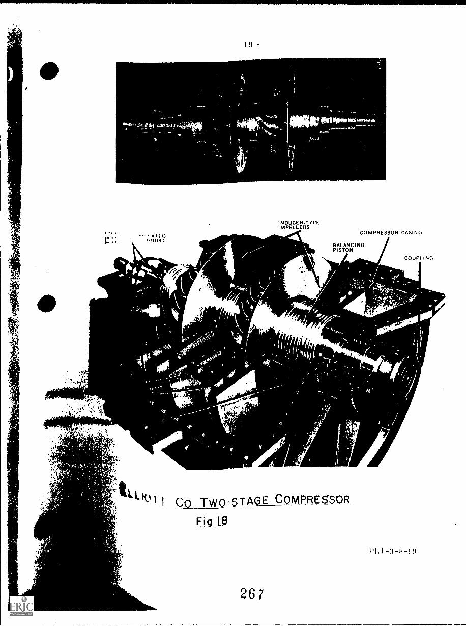
A l f
11110111
4
?
'
" " I CO TWQ-sTAGE COMPRESSOR
0
t
4
INDUCERT YPEIMPELLERS
COMPRESSOR CASING
BALANCINGPISTON
Fig 10
267
. 1,
AIL
COUPI I NG
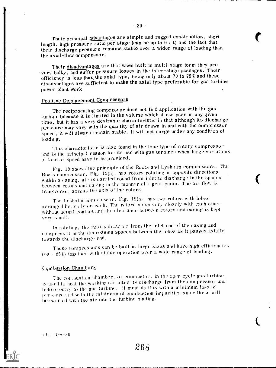
20
Their principal advantages are simple and rugged construction, shortlength, high pressure ratio per stage (can be up to 6 and the fact thattheir discharge pressure remains stable over a wider range of loading thanthe axial-flow compressor.
Their disadvantages are that when built in multi-stage form they arevery bulky, and suffer pressure losses in the inter-stage passages. Theirefficiency is less than. the axial type, being only about 70 to 75% and thesedisadvantages are sufficient to make the axial type preferable for gas turbinepower plant work.
Positive Displacement Compressors
The reciprocating compressor does not find application with the gasturbine because it is limited in the volume which it can pass in any giventime, but it has a very desirable characteristic in that although its dischargepressure may vary with the quantity of air drawn in and with the compressorspeed, it will always remain stable. It will not surge under any condition ofloading.
This characteristic is also found in the lobe type of rotary compressorand is the principal reason for its use with gas turbines when large variationsof load or speed have to be provided.
19 shows the principle of the Roots and Lysholm compressors. The
Roots compressor. Fig. 19(a) . has rotors rotating in opposite directionswithin a casing, air is carried round from inlet to discharge in the spacesbetween rotors and casing in the manner of a gear pump. The air flow istransverse, across the axis of the rotors.
The I.vsholm compressor, Fig. 19(b), has two rotors With lobes
arranged 11(.1 iC11 11V on C:1(.11. The rotors mesh very closely with each otherwithout actual contact and the clearance between rotors and casing is keptvery small.
In rotating, the rotors draw air from the inlet end of the casing and
compress it in the decreasing spaces between the lobes as it passes axiallytowards the discharge end.
These compressors can he built in large sizes and have high efficiencies
(tio 85') together with stable operation over a wide range of loading.
Combustion Chambers
The comoustion chamber. or combustor, in the open cycle gas turbineis used to heat the working air after its discharge from the compressor and
b,,fore entry to the gas turbine. It must do this with a minimum loss ofpressure and with the minimum of combustion impurities since thesebe carried with the air into the turbine Wading,
26d

Inlet
21
Outlet
Inlet
ROOTS COMPRESSOR(a)
Outlet
LYSHOLM COMPRESSOR(b)
Fig. 19
About 20 per cent of the air entering the combustor is mixed withthe fuel in the flame tube as combustion air; the remainder 8Cflows on the outside of the tube and services as cooling air.
She temperature of the burning gases in the tube will be 1370°C to1050 C but the final mixture of the air and hot gas leaving the combustoris limited to the temperature that the turbine Wading can withstand overits working life. This is about 050 to 700 C in present clay practice sothat the cooling air and hot gas must be thoroughly mixed before leavingthe combugtor.
Some of the gas turbine designs use a single, large volume combustorand others a series of smaller combustors disposed radially around theengine between the compressor and the turbine.
Generally the large combustion chamber will be used when a regen-erator is included in the plant or where heavy oil is to be the fuel used
1)1.:1-3-s-21
26J

- 22 -
Fig. 20 shows a section of a combustion chamber of the single type as used byBrown Boveri. The air inlet is located low down and the air flows upwards betweenthe inner and outer jackets. Approximately halfway up some of the air is mixed withthe combustion gases through adjustable mixing nozzles; the remaining air serves tocool the telescopically arranged cylindrical sections forming the inner tube, finallyflowing through the annular spaces between sections. Almost 20% of the total inletair reaches the top of the combustor and enters the swirler to act as combustion airfor the fuel. An electrically heated ignition rod is positioned close to the swirler.
Fig. 21 illustrates a section through a combustor used by Associated ElectricalIndustries (Canada) Ltd. Six of these combustors are used on a machine of 6.5MW output burning natural gas or distillate oil.
Each combustor is made up of an inner chamber, which is carried on radialpins to allow relative expansion, and an outer casing. Interconnecting pipes areprovided between the six combustors to give uniform combustion conditions and tocarry the flame from one to the other during the starting sequence, only two of thecombustors carry igniter elements.
Turbines
Gas turbines use impulse and reaction blading, working on the same principlesas the blading in steam turbines. The main difference between gas and steamturbine Wading arses from the difference between the working medium. Gasturbines have a much less number of stages because the total pressure dropavailable is relatively small. The spacing of the blades is much greater becauseof the high volume flow.
The stresses in the turbine rotors. and Wading are high because of high gastemperatures. In order to withstand this, the rotors arc made from heat resistingsteel, and owing to the difficulty of making large forgings of this material therotors are generally made up of discs bolted or welded together.
Fig. 22 shows a s, ;lion through a Brown Bovcri gas turbine set in which boththe gas turbine and the axial flow compressor rotors arc made up of welded discs.
Fig. 23, (a) and (b), show a Westinghouse Gas turbine rotor of boltedconstruction.
Gas turbine Wading is made of heat resisting steel, forged and machined toshape. Steps are taken in some designs to cool the blading, using hollow Wadingwith sonic coolant such as comrressed air flowing through. Figs. 24 (a) and (b)show a turbine moving, blade and a turbine fixed blading half diaphragm respective-ly, manufactured by A.E.1. Co.
270
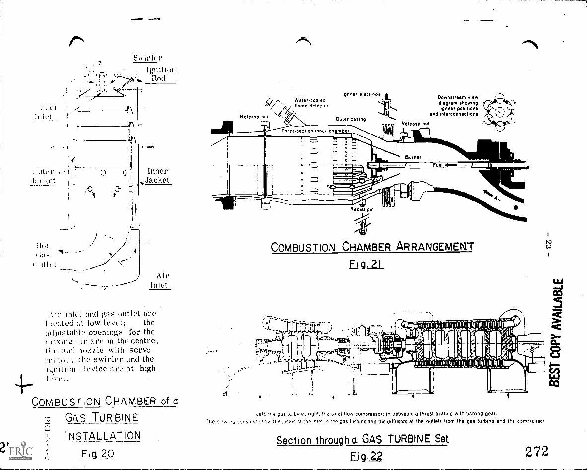
1
g.
hltl'rIaeket
HotCI s
): I
A.
4(c
SwirlerIgnition
Rod
/ 4
Inner,,Jacket
AirInlet
inIct and gas outlet arelocated :it low level; theadlustahle openings for the
are in the centre;thc fuel nozzle with servo-motor, the swirler and theignition device are at highI,'-vet.
COMBUSTION CHAMBER of a
GAS TURBINE
7. INSTALLATION
Fig 20f
Wale rcooledname detector
Igniter electrode
Release nut
Downstream viewdiagram showingigniter positions
and interconnections
COMBUSTION CHAMBER ARRANGEMENT
Fig. 21
I I 1' jil 111.11311114111111111111111111 1, 111
;;;Ag n .4 ,
iip, / ts
c.(4mt:wAl:%210
sok. "N.Ws'
tr e as t..rbine, righ!. tr.i: a kial.flow compressor; in between, a thrust bearing with barring gear,T r;;. the ;it,-.1.et at the ir!e! to the as turbine and the dinusorS at the outlets from the as turbine ar'd the c ,riesSor
Section through a GAS TURBINE Set
,Fig. 22 272

24 -
(a)
TURBINE MOVING BLADE
Last row of blades has not beeninserted. (a)
Individual discs are connected bya Curvic coupling and made rigid by anumber of through bolts.
(6)
GAS TURBINE ROTOR of BOLTED CONSTRUCTION
Fig. 23
PE 1 -3 24Fig.24
(b)
TURBINE FIXED BLADE(Half Diaphragm)

25 -
TURBINE ILLUSTRATIONS
The following illustrations show gas turbines of various types and manu-facture.
Fig. 25 shows a General Electric two-shaft machine for use in mechanicaldrives, rated at 750 kW, thermal efficiency 21%, power turbine shaft speed19,500 rev/min. In this case the main shaft is split between the two turbines.
The air enters at inlet (1), is compressed in the ten stage axial flowqompressor (2) to eight atmospheres, passes to the annular shaped combustor(3), where it is mixed with fuel and ignited by spark plugs which operate onlyduring the starting cycle. The resulting combustion gases first expand throughthe two stage gas generator turbine (4) which drives the compressor and thenthrough a power turbine (5) which is mechanically independent of the gasgenerating sections of the engine. The spent gases are then exhausted toatmosphere (6). The control (7) regulates power output by varying fuel flow.
COMPRESSOR
r.
COMBUSTOR
vP;Ik:77v.4
0 GAS GENERATOR TURBINE
1"44*
tr
0 AIR INLET
.11
I
_.--'11111176%.11 r
CONTROL
POW( R TURBINE
750 kW GENERAL ELECTRIC GAS TURBINE
Fig. 25
0 f
Fig. 26 illustrates a General Electric! machine rated to deliver 9,50oat a thermal efficiency of about 'AG:. It is a simple open cycle, single shaftmachine. The generator (not shown) is driven through gearing at the aircompressor shaft end. The combustion chambers are arranged radial ly aroundthe COMpreSSffi' ing.
274

AIR INTAKECOMBUSTION
COMPRESSOR CHAMBER EXHAUST
275
9,500 kW GENERAL ELECTRIC GAS TURBINE
41. . 441..
mmtiAL.'w
27,4o

--27-
Fig. 27 shows the layout of a Canadian Westinghouse Co. 5 MW gasturbine plant. It is a simple, open cycle, single shaft machine with sixradially arranged combustors
Air
Single Bearing Generator
Main Lubrication Oil Pump Impeller
I.'i V .Auxiliary Assembly----........... o
,.
Pk4 ' 4,243NAxial Air Compressor
, rGos Turbine 'NO w-, ..l'} ii,
GeneratorAir Cooler
agallikt. .0.0.'"
1,*.
Double Helical Reduction Gears
Solid Coupling to Reduction Gear
Compressor Inlet Lill Bearing
Combustion Gharnn
Turbine Exhaust LnJ Hewing
5000 kW CANADIAN WESTINGHOUSE
GAS TURBINE Fig.27
Fig. 2s is a General Electric. Co. dual shaft machine using a regenerative'vole. The air from the compressor discharge is ducted away to the regeneratorheat exehanger %vhere it is heated by the eNhaust gas from the L-p turbine. Itreturns to the large, separate combustion chamber and then to the high pressuretm.bine.
29 is an illustration of a Clark Bros. Co. single stage gas turbinerated at triffil kW with twin, vertical combustion chambers, and a three stagehihine.

2'05\
I
AIR INTAKE
t).
V .
COMPRESSOR
COMBUSTION SYSTEM
g Eftop.
r
PP! 1j 'IsAla
F,
LOW-PRESSURETURBINE
HIGH-PRESSURETURBINE
EXHAUST
xe, &Ali
GENERAL ELECTRIC GAS TURBINE with REGENERATOR
Fig 28
ims
V V5: re I
273 AN

C01111,111101 dischargera
Compressor rotor ofbuil/ up forged
steel discs
combustionchamber
S000. were Jn$ 011101 Speed reduction gear boxciessci. and turbine lot starting and power
lo- single take off to drive.,gin %holt accessories
n e toolv oesigncro.oles olotinra
-ro,o and m.eontrm speedcp.°, 0.1 .;61. ON:iolent
Co,:/ ,ont
reg'o' be
.C%<"aot
-111
14'uwN
Fuel bus is wonprovision tot fuel chsngeoyer
'ender load
Seporole cconbvii.ovi :'nets of hgh,e,;.,v,coute. mdiel cntome alloy
hoepoi posscevsdes.gned to, mos.
efficienr nue., of
gases
Air inlet with orovitiOnfor wet or dry cleaning
verrieollymovnledcombustion chamber prevenft direct
flame impingement on turbineblo Ping and assures more uniform
heat distribution
Turbine inlet duct
., 4.L.,
17 -...P....... el. I .,1w--7-. 44 --
I 1
..Z. ,If....,
i . .117% { 1 , ,o r I ( -!"4b
It 11t IIIL. 4 4gs
t, f Sr tV414 I
..., ,
Sub, w I i--- , 4"14...7.Z",..,.." ti -11ralZmft._,.......
VICII"."1.2.11111.1 s,..*.% %!%\%
7 11":4 ...5.-
,..44466...._.,.:,.. .....k, .1 yr
. . , ..... ....... ,
Three stageturbine rotor ofbuillup, forged
steel discs
° 4
V
Renewable labyrinths "ols of honeycomb
construction on turbinethaft minimize leokoge
,1, : heel bale plot,r ',yr 5" ',on for
supportper,witt hee
'hernialSpantIon
Axial compressor withonsontally spht casing
'5
.-....*4411.1z.....z....1Hr
.-4,17__Na"._ ..Z111111411111.11
Splitstype, full solecismnbeatings external to
hot gases
s,
6700 kW CLARK BROS SINGLE STAGE GAS TURBINE
Fig, 2928 )
" kt**1
.5
.5,
, t S,s %ft+ ;
1.*ao
a/4 .6111111111Pr-
EST COPY AVAILABLE
Fixed support01 output end
281
IV

30
Fig. 30 shows one of the four 25 MW Brown Boveri gas turbines installedin the Port Mann power station of the B. C. Electric Co. Vancouver. Thismachine is arranged for intercooling and reheating. There are two shafts, onecarrying the L-p turbine, L-p compressor and the generator. and the othercarrying the 11-p compressor and 11-p turbine.
Each shaft is fitted with a starting motor. Combustion is carried out intwo large separate combustion chambers, the 11-p heating the air at entry tothe 11-p turbine and the 1,-p reheating the gas before entry to the L-p turbine.An intercooler is fitted between the L'-p and H-p air compressors. Theoperation of this entire power station is arranged to be carried out by remotecontrol from the load dispatch headquart ers of the 13. C. Electric Co,
TURBINE OPERATION AND CONTROL
The most striking difference between steam and gas turbine plants fromthe operation point-of-view is that in the case of a gas turbine of the opencycle type, with the exception of the fuel control. there are no valves in themain air-gas flow circuit. The pressure differences throughout are small.m(1 consequently the pressure loss which would occur through a valve would beexcessive.
I'hus the (want ItV Of air flowing is dependent only on the compressor speedand this is very nearly constant, especially in the case of a machine used forelect rwity generation where the compressor is driven on the same shalt as thegenerator.
The gas turbine output however is dependent, nut only upon the quantity 01oniliw-t in g;ases flowing,. but also upon their energy content. and this allowsload control tt., he carried out by variation of the quantity of fuel burned in the.oinhu-! ton chamber . so that in cases where the machine speed is substantiall.eon.-tant the gas turbine output is dirc.betly proportional to the fuel burned..1 . -in ;le shalt machine driving a generator will be fitted with a speed:.nsit;ve governor \vitt) a temperature sensitive limit control on the fuel flow.While running up to speed. and at times of part loads. Ow speed governor willcontrol the fuel flow and the inlet temperature will be below its optimum figure,.\1 lull lead the temperature control will prevent the turbine inlet temperatureCreme (\ceeding the safe limit set for the blade material. The output obtainable !row the machiny will now be dependent on the ambient air temperature.
Ainhient Air Temperature
vets turbine ratings are usually quoted on the basis of 270C and 100 kPaatmospheric conditions. Variations in the ambient air temperature have a markedtlect upon the efticumey and the output: as a rough approximation the output willvary hy 10'; with 11 C change. In view of this some machines have an elementincluded in the governing system to protect the machine against exces..i,.e feel llowwhich might occur in the ease of overload at a time when the ambient tenwerature ishigh consists of a temperature sensitive element located in the air inlet ductand connected to a Mel valve whirl' will limit the maximum fuf.I flow according to:l1111)H10
P I.: :i. :;ii
282
C
BEST COPY AVAILABLE

- 31 -
LOWPRESSURE COMBUSTION CHAMStR
"k"."11.41.114444,...44140.44LHIGHPRESSURE TURBINE
,......_
1REGULATING VALVECUBICLE
EXHAUST STACK
OWPREURE TURBINEKar.."11.
byLOWPRESSURE
11101,. COMPRESSORHIGHPRESSURE,COMBUSTION CHAMBEh id&lik,1" 4P_.-411W
HIGH.PRESSURE COMPRESSOR
STARTING MOTOR
SPEED INCREASER
.4drai
-11
I
25 MW BROWN BOVERIGAS TURBINE
283
GENERATOR
STARTING MOTOR
EXCITER
PILOT (*c Ft
BEST COPY AVAILABLE

32
Fig 31 shows a diagrammatic arrangement of the fuel system for anA. E.I. gas turbine set of the simple cycle, non-regenerating, single shafttype. Protective devices included are overspeed trip valve, low fuel-gaspressure, low bearing oil pressure, low compressor delivery air pressure.
These protective devices in operation will close the trip valve in thefuel supply line to the combustors. The trip valve 49 normally 113t open byrelay oil pressure acting against a closing spring. In the diagram shown, themanufacturer supplies a duplicate or stand-by trip valve together with pipingand test apparatus in order that the operation of the trip valve can be testeddaily even though the machine is on load.
Fig. 32 illustrates a typical G. E. control diagram for a single shaftgas turbine, showing the layout from the central control panel, through thespeed governor and fuel control system to the turbine. Included is a fuellimit relay sensitive to maximum temperature and to rate of increase oftemperature.
Fig. 33 is a similar diagram for a G. E. dual shaft gas turbine. Herethere are two speed sensitive governors. one to each turbine shaft with ano/.zle control system operating between the two turbines, as in Fig.
ihrII Shalt Machines
When the output of a gas turbine is controlled by variation of the In letgas temperature. the thermal efficiency of the machine suffers at times Of lowload A two shaft or dual shaft machine has the advantage of Ixbing able to controlthe load output by variation of the speed of the gas generating turbine and comp-ressor while maintaining. the inlet gas temperatures to the turbines at theiroptimum iigures.
The type of control, fcir example, is applied to the Brown Hover; machineof the type shown in Fig. 34 in which the 11-p compressor and turbine speed isvaried over a range of 3,000 - 4,500 rev/min, while the L-p or load turbinespeed remains constant and the turbine inlet temperatures are kept at the opti-mum 620°C.
In thu- system a speed sensitive governor on the load (or L--p) turbinecontrols the fuel supply to the combustor' of the gas generating (or I1 -p) turbinein coninnet I011 with a slower acting constant temperature control. The fuel flowlee ihi h,:,(1 turbine is only controlh.d by temperature.
Com rol Systems
The opert ion ot ga turbine plant will involve following generalhinctions (I) Start inp, and stopping. (2) Speed or load control; (3) Temperature:Inc! rate (i1 temperature change conti()I and (4) Emergency shut-down control.
The i.ontrol system employed may be manual. semi-automatic, atito-ai re' or even a fully automatic arrangement with a remote control. The starting
sequence will include nergizing of the auxiliaries, engaging the clutch betweenthe shirting motor and the set. control of the acceleration of the starting motorawl control ol hol increases regniired to bring the machine up to operating
1)1.:1 -3 s
284
BEST COPY MILAN r

Vt
west,Aire
I a )1il
..41FIRING, ACCEL-ERATING,BMAX.FUEL LIMIT RELAY
1,444,40 0414.4ssure Inp
0.4 weed 44.14
.need
.31,4.41 I.l.ip
- 33 -
Rc.ay r,.l supply
1e51
Vent
11.1- H. -
1 Imolg n. dr( rr Idhng or Or( C iv .1111., I .
Dian
iempcs.414,14.COnliol Control valve
0.1 scudtoe Ake,
INV
TN, value
I O.! sha ist
circuit bre.iliertrip
Arnhie.
Starling« motor
LMUnilurspeed
1."1.1 trip
Ovespeedtrip bolt
,41,7 Stop
To oeersosedTest pressure switchI hp valveselector switch
Dram
speed 0..1(11
11. Relay oil supply
IIIII Fuel gas
Rear
414,
FUEL SYSTEM for A.E.I. GAS TURBINE-DIAGRAMMATIC ARRANGEMENT- Fig31
MAX. TEMP, BTEMP RATE FUELLIMIT RELAY
a
FUELCONTROL
SYSTEM
4
FUELEXHAUST
OUT
tirgh energy,io von anrIN
TEMPDETECTORSIGNAL
Igf1.181.
COMBUSTIONCHAMBERS
AIR IN
Typical Functional Control Diagram for
SINGLE SHAFT GAS TURBINE Fig,32
283
NOT INCLUDINGEMERG. TRIPAND ALARMFUNCTIONS
111., 1 -3-M -33
BEST COPY AVAILABLE

BEST COPY AVM! 1.
F (RING, ACCE L-ERAT ING, a MAX.FUEL UMIT RELAY
FUELIN
TEMPOVER NOR
CONTROL ELECT-PANE L OR
MAX. TEMP, II TEMPRATE FUEL LIMIT
RELAY
F UELCONTROLSYSTEM
GOVSIGNAL
E XHAUOU
TEMPERATURECONTROL
RELAY
FUELOUT
GOV. SIGNAL
NOZZLECONTROLSYSTEM
REGEN,
COMB.
CHAMBER
COM P. T UR B
MANUALTEMP.CONTROL
DOES NOT INCLUDEEMERGENCY ALARMAND TRIP FUNCTIONS
Gas
/111
TEMPDETECTORSIGNAL
AIRIN
Typical Functional Control Diagram for
DUAL SHAFT GAS TURBINE Fig.33
34°C
I 'I. I . ;
Et hot's? 2() I
.14 u
Exciters nol shown
Typical System
TEMPERATURES and PRESSURES Fig.34

- 35
GAS TURBINE PERFORMANCE CALCULATIONS
The following terms and values are used when quoting the performance of gasturbines.
1. The Work Ratio
This is the ratio of the net or useful output work delivered by the machine,to the work developed by the turbine.
Work Ratio Turbine output work - Work in ut to com ressorTurbine output work
This will be of the order of 40%, in other words, the compressor takesabout 60% of the total work developed in the turbine.
2. The Air Rate
This is the mass of air required to produce one kWh. It is expressedas the ratio of the heat equivalent of kWh in kilojoules (3600) to the net workdelivered to the shaft per kg of air (kJ).
3 . The Air Fuel Ratio
This is the mass of our used per kg of fuel. It is the ratio of the lowerheating value of the fuel in kJ/kg to the heat supplied by the combustor inkJ/kg.
4. The Fuel Rate or specific fuel consumption
Defined as the mass of fuel in kg required to produce kWh.
It will be equal to Air RateAir Fuel Ratio
5. The following are definitions of some terms used:
Compressor Pressure Ratio - the absolute pressure at the compressordischarge divided by the absolute pressure at the compressoL. inlet.
Machine Efficiencies - refers to the compression efficiency of thecompressor and the engine efficiency of the turbine. That is, compressionefficiency is the ratio of the work required for ideal compression through agiven pressure range, to the actual work required by the compressor.
Turbo-engine efficiency is similar to the 'efficiency ratio' of :1 steamturbine and is the actual work developed by the turbine in expanding the gasever the ideal work available for the expansion.
1) E -3 -8-35
287

3I;
ExampleA gas turbine working on the air standard Brayton cycle takes in 1150 m3/min,
of air at 100 kPa, and -1.5°C. The compressor compression ratio is 5. Fuelburned in the combustor raises the gas temperature of 700°C at the turbine inlet,the turbine exhaust i;ressure is 100 kPa. If the turbine engine efficiency is 85',7,and the compression efficiency is , find the net output power and the thermalefficiency of the plant. (Neglect the pressure drop between compressor outlet andturbine inlet.)
SolutionThe method used can be summarized as follows:
Calculate work done per kg on the air by the compressor and the work doneper kg by the gas in the turbine. The difference will give the net output workper Kg. Find the kg of air flowing per min, then the net output power
kg air/min x net work done (kJ/kg60 kW
and the thermal efficiencyOutput workHeat supplied
These results can be obtained by two methods:(a) By using basic gas laws and calculating the various gas conditions
at each stage in the cycle; or(b) By the use of Gas Tables
In (a), the specific heats of the gas must he assumed to be constant. CI) will
he taken as being 1.005 and y as 1..1 for this example. It will he assumed thatair is the working medium throughout, characteristic constant It 0.2s71 k.1/kg
These assumptions introduce errors and furthermore the calculations can be-come complicated. The ( ;as Tables (b) take into account the variations in specificheat and their readings are consequently more accurate; their use also simplifiesthe working of such problems.
An Enthalpy and Entropy chart for air (similar to the Mollier Chart for steam)is available from information extracted from the Gas Tables, and this allows calcu-lations to be carried out pictorially as was done for steam turbines.
3 The cycle would he as represented onthe 11(P diagram, Fig. 35, point 1 rept e-senting compressor intake conditions.Point 2 will be the point reached afterideal or isentropic compression and point2' that reached after the actual compres-sion.
Point 3 represents the conditions at in-let to the gas turbine. Point .1 would bethe point reached after an ideal expansionand point 1' that of the actual expansion.
288
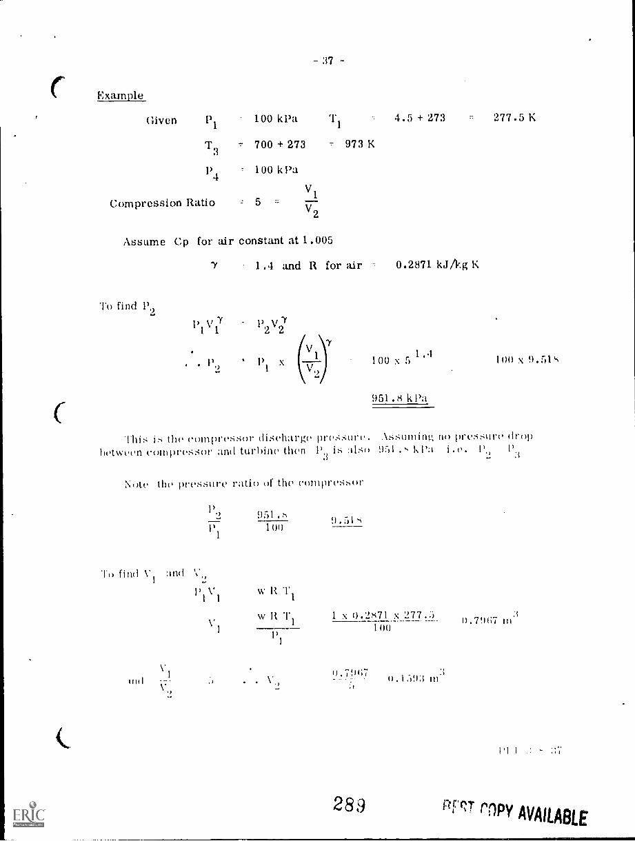
Example
37
Given P1
100 kPa 4.5 + 273 277.5 K
T3 - 700 + 273 973 K
P4 100 k Pa
V1
Compression Ratio V2
Assume Cp for air constant at 1.005
To find P9
1.4 and R for air 0.2871 kJ/kg K
P P kr72 27
. . 100 x 5P1) 1.4
1 x (V,)
ThiS IS the rolnpreSSor diSeharge pre::,Sure.betWeell C01111)reSSOr all(1 tUrbille then 1)3 15 also
Note the pressure ratio of the compressor
11) find VI
1)9
and V.,
1)1V1
V
951.8100
w R T1
w It T1
9 .518
951.8 k Pa
100 x
.1889mini.; no pressure drop951 . 1;1)a i I'
1 x 0.2871 x 277.5 .7907 in100
l),7!)07
289
1).1593 In.'
1'1 1
0,7* r1PY AVAILABLE

987,0 (1901'0) CL6
N
oGa .
I Ig
(.37,(2.0 x CL6
V' I NI
(8' IS) CL6
1- t
IL8Z*0 x I
C6grO "166
( d)
d I-A.
H Za, 7.A
d
7.1, II m
ZA Zd
11 pllij 03,
Z.1, pllij

Compression Efficiency
. . 0.83
39 -
Ideal Temp. ChangeActual Temp. Change
T2 - T1 528 - 277.5
T21 - T1 T21 - 277.5
(528 277.5)= 301.8 + 277.50.83
Turbine Efficiency
. . 0.85
579 K
Actual Temp. ChangeIdeal Temp. Change
T3 - T41
T3 T4973 T41973 -511
'1'1 973 - 0.85 (973 511) 973 393
580 K
Work done by Compressor/kg of air (Ideal)
Cp (T9 Ti)
1.005 (528 - 277.5) 26.1 k.1/kg
Actual work done/kg
Work done by turbine/kg of gas
2640.83 318.1 k.1/kg
C p (T3 - T4)
1.005 (973 - 511) 461..1 k.1/kg
. \rtu :tl work done,/1:)2; 161.3 x 0.45 39.1.7 kJ /1:11
Net work output/kg (Ideal) 161.3 26.1 2(10.3 k.1/kg.
Net worl out pu /kg (Ac tual) 39.1.7 318. 1 76.26 k.1/ky
291
I )I'. I -.5 -4 -39
8EST COPY AVAILABLE
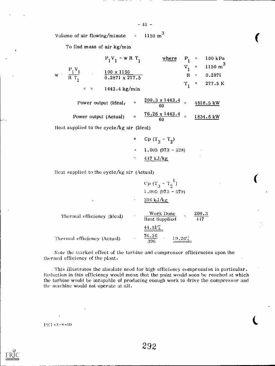
Volume of air flowing/minute
To find mass of air kg/min
P1
V1 = w R T1 where P1 = 100 kPa
V1 = 1150 m3131V1 100 x 1150
w R = 0.2871R T1 0.2871 x 277.5
- 40 -
= 1150 m3
T1 277.5 K1443.4 kg/min
Power output (Ideal,
Power output (Actual)
200.3 x 1443.460
76.26 x 1443.460
Heat supplied to the cycle/kg air (Ideal)
Cp (T3 T2)
1.005 (973 528)
447 kJ/kg
Heat supplied to the cycle/kg air (Actual)
Thermal efficiency (Ideal)
Thermal efficiency (Actual)
Cp (13 121)
1.005 (97:3 - 579)
396 kJ/kg
Work DoneHeat Supplied
44.810
76.26396
19.26
4818.5 kW
1834.6 kW
200.3447
Note the marked effect of the turbine and compressor efficiencies upon thethermal efficiency of the plant.
This illustrates the absolute need for high efficiency compression in particular.Reduction in this efficiency would mean that the point would soon be reached at whichthe turbine would be incapable of producing enough work to drive the compressor andthe machine would not operate at all.
l 'I.: I -3 -40
292

- 41 -
GENERAL INSTRUCTIONSfor Starting and Stopping
As in the case of steam turbines the manufacturers of any particular gasturbine set will give precise instructions for its operation and these should befollowed very closely. The following can be taken as general remarks on thesubject.
Starting
Check the lubricating oil tank for correct level and start the auxiliary oilpump. See that this is delivering oil to all bearings.
Check the cooling system and start the circulating water pumps. This willsupply oil coolers, generator air coolers, and compressor intercoolers, wherethese are fitted.
Check that the fuel supply valves to the combustors are closed off.
The larger machines will be fitted with jacking oil pumps; in this case startthis pump in order to ease the mass of the shafts in the bearings.
Start the barring motor and then the starting motor. Check the startingcurrent and speed as this motor accelerates the turbine shaft up to therecommended speed. This must be sufficient to enable the air compressor tosupply air to the combustors and will De upwards of 20% of the full speed.
As a rough guide it can be taken that a gas turbine set requires a rotationof about 50% of the full rated speed to obtain a sufficiently high air pressureto be self sustaining.
The starting motor power required to attain this speed in I minute will beabout 5% of the rated output of the set.
Supply ignition to the combustors and begin admitting fuel. See that ignitionis satisfactory. Increase fuel and when combustion is stable switch off theigr .tion.
The temperature at inlet to the turbine must be carefully watched as theturbine speed increases, and kept within the recommended limit.
The starting motor is generally arranged to cut out automatically by acentrifugal clutch or other means.
The main lubricating oil pump and the spe,'d governor will be gear-drivenfrom the main shaft and will come into operation as the speed builds up. Withinabout 1(Y of normal running speed, the governor will take control. The main oilpuii) will indicate full running condition when its oil discharge pressure reachesa steady figure.
PEI-A-m-11

The total time taken in running up from standstill will be about 10 minutes.Adjust the machine speed to correspond with the system frequency with whichthe generator is to be paralleled, synchronize and close main switch.
Raise load as required. A gas turbine can be loaded rapidly since theexpansion problems are not so acute as a steam turbine. The time taken fromno load to full load on a 30 MW machine is quoted by Brown Boveri as beingabout 10 minutes.
Shutting Down
Reduce the load on the generator.
Open main switch.
Leave the machine idling for a few minutes.
Start the auxiliary oil pump and see that it is delivering oil satisfactorily.
Change over fuel supply to hand control and shut off fuel.
See that ignition ceases in the combustor and allow the machine to cometo rest.
During this time control the circulating water supplies to give the requiredlubricating oil temperatures.
After the machine has stopped, run the jacking oil pump and then start thebarring motor to keep the shafts rotating slowly during the cooling down period.
Notes on Operating
Whilst in operation the gas turbine will require supervision to ensure thatlubricating oil flow and temperatures are satisfactory, cooling water flow isadequate to maintain oil cooler and generator air cooler conditions, correctoperation of inlet-gas temperature regulator etc. Some machines, for example,Brown Boveri are provided with sight glasses into the combustors to observethe combustion conditions, and into the turbine inlet stage to observe the appear-ance of the inlet stationary diaphragm blading and the first row of moving
Safety devices, such as the machine over-speed trip, should be tested atregular intervals. Sequential interlocks are often provided to protect the machineagainst operation (4 starting motor and ignition in incorrect sequence. Ignitionshould not he switched on when the machine is standing since there may have beensome fuel leakage into the combustor and there is danger of explosion under theseconditions. Running the compressor by the starting motor will ensure sufficientair flow to dispel any residual fuel gases.
PE 1 -s -12
294

QUESTIONS
POWER ENGINEERINGFirst ClassSect. 3 Lect. 8
1. In what circumstances would you expect to find a gas turbineplant chosen as the prime mover for power production or forelectricity generation?
2. Explain with the aid of a diagram the layout and operation of asimple, open cycle gas turbine.
3. Review the possible improvements to this cycle.
4. Why is a starter motor necessary for a gas turbine.
5. What is meant by a closed cycle as applied to a gas turbine.Give the advantages and disadvantages.
6. What is a Free Piston gas generator, how does it operate?
7. Give the types of air compressors used with gas turbines.Why are these types chosen?
8. What are the fuels used for gas turbines?Can coal be used for this purpose?
9. State the main differences between steam and gas turbines.
10. How is load control carried out on a gas turbine used for electricitygeneration?
PEI -3 -8-44
295