DOCUMENT RESUME CE 001 424 Overhaul, … overhaul forms, the measurments. recorded on overhaul...
31
DOCUMENT RESUME BD 092 695 CE 001 424 TITLE Overhaul, Inspection and Repair of Reciprocating Engines 2 (Course Outline), Aviation Mechanics (Power Plant): 9055.02. INSTITUTION Dade County Public Schools,. Miami, Fla. PUB. DATE 71 NOTE 30p.; An Authorized Course of Instruction for the Quinmester Program (7- ' EDES PRICE MF-$0.75 HC-$1.85 PLUS POSTAGE DESCRIPTORS Audiovisual Aids; *Aviation Mechanics; Aviation Technology; Behavioral Objectives; *Curriculum Guides; *High School Curriculum; Job Skills; Secondary Grades; *Technical Education; Vocational Education IDENTIFIERS *Quinmester Program ABSTRACT The course outlined is the second of two designed to help a trainee acquire the knowledge and become proficient in the" skills associated with the overhaul, inspection, and repair of reciprocating engines. The knowledge and skills are necessary to pass the Powerplant Theory and Maintenence section of the.Federal Aviation Administration examination for the powerplant mechanic's license. The course is composed'of one block of several units requiring one quinmester.of 135 hours. Seven pages of Course.outline are folloWed by five pages-of specific behavioral objectives; a posttest is appended. Basic and supplementary references, Federal Aviation Agency .publications, and five .instructional films are included in the bibliography. (Author/AJ) 4
Transcript of DOCUMENT RESUME CE 001 424 Overhaul, … overhaul forms, the measurments. recorded on overhaul...
DOCUMENT RESUME
BD 092 695 CE 001 424
TITLE Overhaul, Inspection and Repair of ReciprocatingEngines 2 (Course Outline), Aviation Mechanics (PowerPlant): 9055.02.
INSTITUTION Dade County Public Schools,. Miami, Fla.PUB. DATE 71NOTE 30p.; An Authorized Course of Instruction for the
Quinmester Program(7- '
EDES PRICE MF-$0.75 HC-$1.85 PLUS POSTAGEDESCRIPTORS Audiovisual Aids; *Aviation Mechanics; Aviation
Technology; Behavioral Objectives; *CurriculumGuides; *High School Curriculum; Job Skills;Secondary Grades; *Technical Education; VocationalEducation
IDENTIFIERS *Quinmester Program
ABSTRACTThe course outlined is the second of two designed to
help a trainee acquire the knowledge and become proficient in the"skills associated with the overhaul, inspection, and repair ofreciprocating engines. The knowledge and skills are necessary to passthe Powerplant Theory and Maintenence section of the.Federal AviationAdministration examination for the powerplant mechanic's license. Thecourse is composed'of one block of several units requiring onequinmester.of 135 hours. Seven pages of Course.outline are folloWedby five pages-of specific behavioral objectives; a posttest isappended. Basic and supplementary references, Federal Aviation Agency
.publications, and five .instructional films are included in thebibliography. (Author/AJ)
4
AUTHORIZED COURSE OF INSTRUCTION FOR THE
U.S DEPARTMENTOF HEALTH,
EDUCATION II WELFARENATIONAL INSTITUTE OF
EDUCATIONTHIS DOCUMENT HAS BEEN REPRO
OL/CED EXACTLY AS RECEIVED FROM
THE PERSON ORORGANIZATION ORIGIN
:.TING IT POINTS OF VIER OR OPINIONS
ra TED DO NOT NECESSARILY PEPPE
SENT OFFICIAL NATIONAL NST(TtirEOFEDUCATION POSITION OP POLICY
(OverhaulIATIONMECHANICS (Power Plant)
Ins, Inspection and Repair of Reciprocating Engines II)
Department 48 - Course 9055.02
E.11:
-CDMwCD
C5CDC=2M4no
rc,ColC5DCCDCDrGo,
'DIVISION OF INSTRUCTION 10.71

DADE COUNTY PUBLIC scHooLs1 410 NOBTHEAST SECOND AVENUE
MIAMI, FLORIDA 33132
11
Course Outline
AVIATION MECHANICS (Power Plant)(Overhaul, Inspection and Repair of Reciprocating Engines II)
Department 48 - Course 9055.02
the division of
VOCATIONAL, TECHNICAL AND ADULT EDUCATION

DADE COUNTY SCHOOL BOARD
Mr. William Lehman, ChairmanMr. G. Holmes Braddock, Vice-Chairman
Mrs. Ethel BeckhamMrs. Crutcher Harrison
Mrs. Anna Brenner MeyersDr. Ben Sheppard
Mr. William H. Turner
Dr. E. L. Whigham, Superintendent of SchoolsDade County Public Schools
Miami, Florida 33132
Published by the Dade County School Board

9055
Course Description
Overhaul, Inspection andRepair of Reciprocating
48 9055.02 Engines IIState Category County Dept. County Course Course Title
A continuation of course 9055.01 with emphasis on the,practical application of theories presented.
Indicator of Success: Successful completion of courses9073.01, 9073.02, 9073.03, 9073.04 and 9055.01.

PREFACE
The course outline that follows has been prepared as a
guide to help the trainee acquire the knowledge and become
proficient in the skills associated with the overhaul, in-
spection and repair of reciprocating engines. This course
is the second of two courses on the overhaul, inspection and
repair of reciprocating engines. Successful completion of
this course 'plus courses 9055.01, 9055.03, 905.04 will
provide the trainee with the skills and knowledge required
to pass the Powerplant Theory and Maintenance section of the
Federal Aviation Administration examination for the Power-
plant Mechanic's License. Courses 9073.01, 9073.02, 9073.03,
9073.04.and 9055.01 are prerequisites for this course. This
course is composed of one block of several units requiring
one quinmester of 135 hours.
Great emphasis will be placed on the use of audio
visual aids and instruction sheets of various types. A list
of behavioral objectives the-trainee will be required to
perform is included. Following each unit title will be found
in parentheses several letters and numbers designating the
time spent in terms of theory and shop work: EIT indicates
estimated instructional time, T indicates time spent in
theory or classroom work and L/S indicates time spent in_ .. _
laboratory or shop work.

The level 1 following a unit indicates the student must
have knowledge of general principles but no practical appli-
cation nor manipulative skill, and instruction is given by
lecture, demonstration, and discussion.
The level 2 following a unit indicates the student must
have knowledge of general principles and limited practical
application; sufficient manipulative skill to perform basic
operations; and instruction is given by .lecture. demonstration,
discussion, and limited practical applicatiori.
The level 3 following a unit indicates the student must
have knowledge of general principles and performance of a
high degree of practical application, and sufficient mani-
pulative skill to accomplish return-to-service operations.
Instruction is given by lecture, demonstration, discussion,
and a high degree of practical application.
This outline was developed through the cooperative
effortS of the instructional and supervisory persdnnei, the
,Quinmester Advisory Committee, and the Vocational Teacher
Education Service, and has been approved by the Dade County
Vocational Cui,riculum Committee.
11.

PREFACEGOALS .
BLOCK
TABLE OF CON LENT'wlth Suggested Hourly Breakdown
Page
iv
I. RECIPROCATING ENGINE OVERHAUL PROCEDURES(135 hours)Overhaul Reciprocating Engine 1
Inspection and Repair of. ReciprocatingEngines . . 3
II. QUINMESTER POST TEST
BEHAVIORAL OBJECTIVES . . . Fl
BIBLIOGRAPHY . 13APPENDIY: QUINMESTER POST TEST SAMPLE . . . 17
iii

GOALS
The aviation maintenance technician must be able todemonstrate:
1. Knowledge of engine operation and construction techniques.
2. The various procedures necessary to overhaul, inspect,and repair reciprocating engines.
3. Knowledge of methods of engine inspection.
Knowledge of methods of engine overhaul.
5. The ability to locate information in manufacturer'soverhaul and maintenance manuals and utilize same.
The ability to assume the responsibilities necessary tobecome an aviation maintenance technician.
iv

Course Outline
AVIATION MECHANICS (Power,Plant)(Overhaul, Inspection and Repair of Reciprocating Engines II)
Department 48 - Course 9055.02
I. RECIPROCATING ENGINE OVERHAUL Pl.nCEDURES (135 hours)
A. Overhaul Reciprocating Engine(Level - 3) .(EIT-55 hrs) (T-14 hrs) (L/S-41 hrs)
1. Preparing a Work Station and Engine for Overhaula. Engine work station
(1) Select proper stand for engine tooverhaul
(2) Check.for hazards that can be created inwork area
'(3) Guard against contamination to engine. parts in the work area
(4) Selection of proper parts rackS andreasons
b. Preparation of engine(1 Pre-cleaning procedure(2) Means of locating parts to point.of
removal(3) Means of hoisting engine(4) Marking of special location of parts(5) Procedure for installing engine in work
stand(6) Procedure for draining and inspecting
engine oil and screens(7) Preparing engine for shipping containers
Overhatiling the Reciprocating Enginea. Equipment
(1) Hand tools required.(2) Power equipment required(3) Type and advantage of overhaul stands(4) Special tools
b. Disassembly(1) Determining disassembly procedure for
engine type(2) Technique for removing frozen fasteners(3) Protection of engine parts during dis-
assembly(4) Separating parting surfaces with gaskets
!of "0" rings
2.
-1-

I. RhCIPROCA PING ENGINE OVERHAUL PROCEDUEES Contd.)
c. Parts storab!(1) Means of storinv: parts(2) Correct Inbeling of parts(3) Correct grouping of parts
d. Cleaning(1) Methods of cleaning parts(2) Degreasing and decarbonizing.(3) ,Cleaning internal passages(4) Use of gunk(5) Abrasive cleaning
.(6) Cleaning of ball and roller bearings(7) Magnetic affect on bearings(8) Drying and protecting bearings
e. inspection procedur,7.7
(1) Checking for fits and clearances(2) Checking studs.(3) IdentifiCation of
(a) Flaking(b) Pitting(c) Galling(d) Excessive wear(e) Loose liners
(4) Inspection of bushings() Checking bushings for cracks, scoring,
overheating. looseness and excessive wear(6) Inspection techniques for crankcase,
brackets, adapters, sumps and cover platesfor cracks, nicks, breaks, surface smooth-ness, of 'parting surfaces, obstructionsin drill passages, tightness of plugs.andmutilation of internal threads
(7) Checking gears for wear pattern, pittingfatigue and cracks
(A) Checking shafts for runout and conditionsoCthreads, splines and journals as wellas for wear and fatigue
(9) Inspect oil pipes for dents, cracks,nicks, flange condition and fit
(10) Procedure for magnafluxing(11) Procedure for zyglo Inspection(12) Dy-check and its use(13) Visual inspection using a magnifying
glass,
-2-

I. BECIPROCPTING ENGINE OVERHAUL PROCEDURES (Contd.)
f. InspectLon sheet and tables of limits used inoverhaul(1) Use of table of limits and who determines
them(2)' The use of the table of limits(3) Engine overhaul forms, the measurments
recorded on overhaul forms, and thelimits found there
g. The use of inspection gauges, indicator anddevices(1) The use of, micrometers, hole gauges and
telescoping gaugesfor engine partsinspection
(2) Checking runout with dial indicator(3). The use of go-no-go gauges
h. Approved engine repairs(1) Acceptable repairs for various engine parts(2) Techniques in replacing parts requiring.
temperature differential(3) In replacing partschee;% for meeting
manufacturer's s,tandards and mating ofparts when necessary-
i. Engine assembly(1) Procedure for assembly(2) Torque.and clearance limits(3) Assembly procedure and checking for
opposed engines(4) Internal and external safetying(5) Engine internal timing(6) Installation of accessories and external
timing(7) Preparing engine for storage
B. Inspection and Repair of Reciprocating EngineshThs1---(L/S":52-hrS)
1. Cylinder Inspectiona. Techniques of cylinder' inspection
(1) Checking for out of round, taper and choke(2) Color coding of aircraft cylinders
Checking the'areas of greatest wear ina cylinder

I. RECIPROCATING ENGINE OVERHAUL PROCEDURES (Contd.)
b. Limits and tolerances(1) Where to find limits for dimensional
inspection(2) The limits that would apply to a cylinder
2. Detection of Cracks and Defects in CrankcaseAssembliesa. Cleaning crankcase assemblies
(1) Materials generally used in'crankcasecleaning
(2) Handling and cleaning of crankcase madeof special alloys
b. Inspection'of crankcase assemblies(1) Types of speCialized inspection
(a) Zyglo(b) X-ray(c) Dy-check
(2) Oil flow chec,,. procedure(3) Removal and installation of plugs in
crankcase passageways(4) The use of visual inspection and dimensional
inspectionStud Removal and Installationa. Removal of damaged studs
(1) Tools used in stud removal(2) Procedure used in stud removal
b. Removal of broken studs(1) Tools used to remove broken stud(2), Procedures used for removal of broken stud
'(3) Procedure for special alloyc. Installing studs,
'(1) Identify oversized studs(2) Identify alloy of studs(3) Installation without special tools
d. Helicoil(1) Description of a helicoil(2) Usage(3) Installation(4) Removal
Identification of Serviceable Bearinga. Visual inspection of bearing
(1) Indication of acid etch(2) Source of acid etch(3) Effect of inadequate lubrication on
bearings

I. RECIPROCATING ENGINE OVERHAUL PROCEDURES (Contd.)
(4) Effect of oil pressure in engine withworn bearing
(5) Effect of bearing misalignment duringinstallation on bearing wear
b. Dimensional inspection of bearing(1) Inside diameters
'(2) Outside diameters5. Crankshaft Inspection
a. Crankshaft runout(1) Flange - checking runout before disassembly(2) Shaft
(a) Use of v-block or rollers whenchecking shaft runout
(b) Checking center mains for alignment(c) Use of dial indicator on a crank-
shaftb. Measurements
(1) Procedures for measuring bearing journals(2).. Determining out of round of journals(3) After dimensional inspection x-ray
crankshaft6. Piston'and Knuckle Pin Retainers
a. Piston pin retainers(1) Full-floating piston pin2) Types of piston pin,retaihers(3) Procedure for removal and installation
b. Knuckle pin retainers(1) Determine the serviceability of knuckle pin
retainers(2) Pre:positioned knuckle pins
7. Cams and Cam-Followersa. Cam rings
(1) Number of cam tracks per ring or plate(2) Purpose of a ramp on a cam lobe
b. Cam shafts(1) Types of engines that use cam shafts(2) Number of lobes used on a shaft in
relation to numbers of valves in theengine
(3) Procedure for measuring cam lobe height
-5-

RECIPROCATING ENGINE OVERHAUL PROCEDURES (Contd.)
c. Cam followers(1) Zerolash valve lifters(2) Interchangeability of parts of a zero-
lash valve lifter(3) Effect of flat or stuc:e: lifters on valve
'operation8. Valve and Valve Seat Inspection and Rework.
a. Valve types and materials(1) Aircraft exhaust valve requirements(2) Aircraft intake valve requirements(3) The purpose of sodium filled valves(4) The hazards in sodium filled valveS(5) The use and advantage of stellite in valve
constructionb. Valve seat and face angle
(1) The purpose of valve face angle(2) The normal angle' for exhaust valve and
intake valve(3) Valve seat construction(4) Means of retaining valve seats in cylinder
headc. Valve guides
(1) Valve guide installation procedure(2) The relationship of valve to the seat
and guide(3) Valve seat installation procedure(4) Determining valve stretch(5) Method of obtaining a gas tight seal
between the valve and its seat(6) The desired width of contact between
the valve and seat,9. Cylinder Assembly Installation and Construction
a. Construction features(1) Piston
(a) Cam ground pistons(b) The reason for large piston to
cylinder wall clearances(c) Types of pistons
(2) Rings(a) The function of a piston ring(b) The reason for ring clearance

RECIPROCATING ENGINE OVERHAUL PROCEDURES (Contd.)
(3) Ring, piston, and cylinder fit(a) The reason for chrome plating rings(b) Precautions used with chrome rings(c) Ring side clearance(d) Ring end gap(e) Procedure for checking different
ring typesb. Use of manuals
(1) Procedures(a) Cyflnder attaching methods(b) Installing the master rod cylinder(c) Checking rings before cylinder
installation(d) Checking crankcase base area before
cylinder installation(e) Lubrication of cylinders, piston,
and ring assemblies(f) Ring compressors(g) Cylinder hold down types
(2) Special tools(a) Tools for torquing cylinder hold
down nuts(b) Torquing sequence for cylinder hold
downs .
II. QUINMES2ER POST TEST

BEHAVIORAL OBJECHVES
BMCK E - EECEPIWCATBO ENOENE OVUHAUL nOCEDUREI
A.. Overhaul Reclprocating Engine
1. Preparing a Work Station and Engine for OverhaulGiven:.
A written list of twenty safe and unsafe.practices (normally associated with handlingof engine and the preparation of a workstation prior to engine overhaul), an engineand a work station.
Performance:The student will recognize all hazardousconditions and arrange the engine.in the workstation for an engine overhaul.
Standard:All hazardous practices will be identified.The sequence of operations to prepare thework station will be in general agreement withcommon industry.practice.
2. Overhauling the Reciprocating EngineGiven:
A small opposed or radial engine, a workstation having an engine overhaul stand andnecessary tables and parts racks, necessaryhand and specialized tools and fixtures, anoverhaul manual and overhaul inspection sheets.
Performance:----UsIng-the -overhaul--manua-I,--the-student will
disassemble the engine, label and store theparts, clean the parts, inspect the partsphysically, visually, and with a nondestructivetesting; measure the parts for wea!,, andIdentify those parts that are reusable from thetable of limits; reassemble the engine; andrecord all findings and recommendations on theoverhaul inspection sheets.
Standard:All procedures followed, recorded data on theoverhaul inspection sheets, and recommendationsfor parts rejection will be correct for theparticular engine and the engine will beassembled mechanically correct.

B. Inspection and Repair of Reciprocating Engines
1. Cylinder InspeCtion .
Given:A cylinder from an aircraft engine, appropriateinspection tools and reference manuals.
Performance:The student will inspect and determine theserviceability of a cylinder.
Standard:The student will correctly judge whether thecylinder should be rejected or returned toservice.
2. Detection of Cracks and Defects in CrankcaseAssembliesGiven:
Written list of probable defects, crankcasesthat exhibit one or more of the defects, andthe necessary inspection equipment.
Performance:Provided with a list of the probable defects,the student will. clean, visually inspect anddetect the defects present in the specimencrankcase assemblies.
Standard:The student will detect all the defects in thecrankcase assemblies.
3. Stud Removal and InstallationGiven:
An aircraft engine component that has a damagedor broken stud and the necessary tools.
erformance:-The student will remove a damaged stud andinstall a replacement stud.
Standard:.Removal of the damaged stud will not causefurther damage to the component. The replace-ment stud will maintain a class three fit.
4. Identification of Serviceable BearingsGiven:
A random display of bearings which may displayevidence of impending failure, an applicable tableof limits and tolerances and the necessary in-,spection tools.
-5-

Performance:.The student will identify serviceable bearingsby means of visual and dimensional inspection.He will also identify failed or failingbearings within the displayed group of bearings,and when given a written list indicating wherethese bearings are located within an engine,will describe how these bearings could bedetected in an operating engine.
Standard:Inspection .procedure and measurements willmeet return -to- service quality.
5. Crankshaft InspectionGiven:
A crankshaft from an aircraft engine, thenecessary inspection tools and referenceManuals.
Performance:The student will check crankshaft "run-out",measure rod and main bearing Journals andjudge whether the crankshaft meets dimensionaltolerances.
Standard:Inspection procedure and measurements willmeet return-to-service quality.
6. Piston and Knuckle pin RetainersGiven:
Piston, piston pins. master rods and knucklepins with various types of pin retainers andthe applicable manufacturer,.s manuals.
Performance:Provided with examples of the various types ofpistons and knuckle pin retainers, the studentwill correctly name and identify each type.He will remove and reinstall at least one'typeof retainer.
Standard:Removal and reinstallation of the retainerwill be in accordance with the procedurespecified in the manual and will be accomplishedwithout damaging the retainer or engine part.
-10-

Cams and Cam-followersGiven:
P. typical camshaft. cam ring. cam-followers.the precision measuring tools and appropriatereference informatIon.
Performance:Ohe student will identify the components,dimensionally Inspect and describe theoperation of the valve mechanisms. He willdisassemble, assemble and test zero-lashlifters.
standard:Correct nomenclature will be used to identifythe components and describe the operation ofvalve mechanisms. Measurements will be accuratebut components need not be of return-to-servicequality.
Valve and Valve Seat Inspection and ReworkGiven:
An aircraft engine cylinder containing valves,valve springs, appropriate reference informa-tion and the required tools. .
Performance:The student will inspect the valve assemblies,reface and reseat the valves. He will inter-pret the manufacturer's overhaul Instructionsand describe the replacement of valve guidesand Seats.
Standard::'he refaced and reseated' walvs will not leakwhen checked in-accordance with manufacturer'soverhaul instructions."
9. Cylinder Assembly, Installation and ConstructionGiven:
A piston, pin, rings, cylinder assembly. sealsgaskets; necessary tools and reference manuals.
Performance:The student will describe the constructionfeatures of a piston, rings, and cylinderassembly. He will inspect the components,fit the pins and rings to the piston, andinstall the assembly in the cylinder and torquethe cylinder to the engine.

Standard:The student will use correct nomenclature andterminology as part of the description andexplanaLion, r,11 work will be in accordancewith the manufacturer's specifications.
-12-

PIRLIOGE,APHY.
(Overhaul, Inspection and :,apalr of Rectprn,:allnL Engirq.1 LL)
Bay Lc Reference:
1. Cargninr, Lawrence T. and Karvinen, Clifford H.Aerospace Propulsion Power Plants. 4th ed.
Chicago: Educational Publishers, Inc., 1967.
Pp. 677.
2. Northrop Institute of Technology . Powerplants forAerospace Vehicles. 3rd ed. New York: McGraw-Hill Rook Company, Inc., 1965. Pp. 480.
Supplementary References:
1. Brimm, Daniel J. and Boggess; H. dward. AircraftEngine Maintenance. 1st ed. New Yor:: PitmanPublishing Corp., 1940. Pp. 1170.
2. Northrop Institute of Technology. Basic Science forAerospace Vehicles. 3rd ed. New Yorlr: McGraw-1111 Book Company, Inc.-, 1S;''53. Pp.
3. U.R. Civil Aeronautics Administration. Aircraft. PowerPlant Handbook. Technical :.anual 107. ist ed.Washington, D.C.: U.S. Government Printing Office,19119. Pp. 35',;.
4. U.S.. Department of the Air Force. Power PlantMaintenance for Beciprocatins Lnc.ines. AF Manual52-12. 1st ed. Washington. D.C.: U.S. GovernmentPrinting Office. 1953. Pp. 492
5. U.S. Department of the Navy, Airplane ?over Plants.U.S. Navy Manual NAWEPS 00-80T-42. 1st ed.Washington; D.C.: U.S. Government PrintingOffice. Pp. 258.
Federal Aviation Publications:
1. Federal Aviation Administration. Acceptable Methods,Techniques, and Practices-Aircraft inspection andRepair, Advisory Circular 43.13-1. Washingtbn,
-13-

D.C.: U.S. Government Printing Office, 1965.Pp. 232.
2. Federal Aviation Administration. Acceptable Methods,Techniques, and Practices-Aircraft Alterations,Advisory Circular 43.13-2. Washington, D.C..:U.S. Government Printing Office, 1965. Pp. 74.
3. Federal Aviation Administration. Aircraft Engine andPropeller Type Certificate Data Sheets. Washing-ton, D.C.: U.S. Government Printing Off ice, 1968.
4. Federal Aviation Administration. 'Aircraft TypeCertificate Data Sheet and Specifications.Washington, D.C.: U.S. Government PrintingOffice, 1967.
5. Federal Aviation Administration. Airframe and Power -plant Mechanics Examinations .Guide, AdvisoryCircular 65-2A. Washington, D.C.: U.S. Govern-ment Printing Office, 1969. Pp. 63.
6, Federal Aviation Administration. Federal AviacionRegulations Parts: 1, 23, 25, 27, 29, 33, 35,37, 39, 43. 45, 47, 65, 91 and 145, Washington,D.C.: U.S. Government Printing Office, 1969.
7. Federal Aviation Administration. Summary of SUpple-mental Type Certificates. Washington, D.C.:U.S. Government Printing Office, 1965.
Films:
1. 'Inspection and Reconditioning. Piston Assembly. 16mm.20 min. Black and White. Sound. G.T.B. 3-29.
2. Inspection and Reconditioning of Valve Assembly.16mm. 15 min. Black and Whine. Sound, M.B.3-21.
Overhauling the Crankshaft.Asembly. 16mm. 14 min.Black and White. Sound. G.T.. 3-30.
-14-

4. Reassemblink_the EnGine. 16mm. 1P min. Black and
White. Sound. G.P.B. 3-25.
Wright Engine Preliminary DIzlassembly. 16mm. 13
min. Flack and White. sound. G.T.B. 2-3.

APPENDIXQuinmester Post Test Sample

Name
Quinmester Post Test
Date
Multiple Choice Test Items
Score
Each question is followed by four possible answers, selectthe best answer and mark your answer'sheet accordingly..
1. How is the gap in a piston ring measured?1. No measurement is required if the proper ring
is installed2. With a depth gauge while the ring is held in
place on the piston3. With a thickness gauge while the ring is
installed inside the cylinder4. With a go-no-go gauge while the ring is
installed on the proper mandrol
2. How. is the oil that is picked up by the oil control rings.returned to the pump?
1. By machined grooves in the piston skirt2. Through oil holes drilled in the ring grooves3. Through holes in the piston pin4. It remains trapped between the 011 scraper rings
3. Valve guides are installed in the cylinder head by1. evets press2.. threading3. -shrinking4. sweating
4. Piston rings should be installed1. with all ring joints in line2. with all ring joints staggered3. with no clearance between ring joints4. with no clearance between ring joints and
ring grooves
Which of the followtng would be an acceptable.cOnditionfor a reconditioned cylinder?
1. A cracked cylinder head2. A cracked rocker arm boss3.--aprOper Cleaning .after reboring4. A cracked cylinder head cooling fin
-17-

Small scores or scratches on the head or lands of analuminuM piston may be removed by
1. using a rotary wire brush2. using a fine grade file'3. stoning only the excessive build up around the
Scratch4. .hand stoning or using crocus. cloth
7. The greatest wear in a cylinder is at the1. center2'. top3. center near thEl bottomb. bottom of a slanted cylinder
8. What is the correct method to use when inspecting intakeand exhaust valves for stretch?
1: -Place the valve on a flat surface and measurethe stem with a verier height gauge
2. Measure the stem length with an outsidemicrometer caliper
3. Use a contour or stretch gauge4. Use a valve depth gauge
9. On a single row radial engine, why should the kmIckelpins be fastened securely?
1. So that the oil holes will not become misaligned2. fo minimize wear3. fo prevent slippage between the articulated
rod and pin4. To reduce torsional vibration caused by engine
firing impulses
10. Why are floating pins used'in aircraft pistons?1. 20 allow movement between pin and piston2, To allow movement between piston and connecting
rod3. To allow movement between pin, piston and
connecting rod4, To allow movement between piston and cylinder
11. Which of the following are symptoms of a weak engine?1. Below normal MAP required to obtain normal RPM2. Backfiring and or detonation3. Excessive MAP required to obtain normal RPM4. Intermittent misfiring at high RPM
-18-

12. A mechanic should know that the Installation of baffles,brackets, etc., under cylinder hold down nuts and capscrews
1. is not considered good practice and should bediscouraged
2. may cause loosening of the nuts or cap screwseven though they were properly tightened andlocked at installation
3. is absolutely forbidden if parts are made fromaluminum or other soft metals
4. is not recommended since all of the abovestatements are true
13. Why are pistons cam ground?1. To allow for equal wear on the mastIr rod2. For proper fit at operating temper4res3. To improve volumetric efficiency4. To equalize wear on cylinders which are not
placed vertically
14. What material is used for piston compression rings?1. Aluminum alloy2. Steel alloy3. Cast iron4. Aluminum
15. How should magnesium engine parts be cleaned?1. In a solution of caustic soda2. With transpo and gunk3. With a neutral solvent and light scraping4. By sand blasting
16. Why is the piston-to-cylinder clearance greater inaircraft engines?
1. The pistons have different rates of thermalexpansion
2. Aircraft engines run at higher RPM than otherengines
3. Aircraft engines operate at higher temperatures4. Compression ratios are higher and require
higher clearances
9-

17. What is the reason for a "Choke Bore" in an enginecylinder?
1. To force the piston closed to insure a better.gas seal at the top of the cylinder
2. To insure no taper at normal operatingtemperatures
3. To give added clearance to rings and pistonsat high operating temperatures
4. To allow for piston wear.as the engine operates
18. The purpose of the aluminum caps in the ends of the.piston pin is to
1. form a plug so that oil can be forced into thepin for cooling
2. prevent the pin from scoring the cylinder3. allow for thermal expansion of the pin4. steel caps are used, not aluminum
19. Carbon is most likely to form under and on1. the lower oil control ring2. all of the piston rings to approximately the
same degree3. only on the upper oil scraper ring42 the topmost compression ring
20. A tapered oil control ring has been installed upside down,this will cause
1. low oil pressure.2. low oil consumption3. high oil consumption4. high oil pressure
21. Push rods are removed when the piston is at the1. top center of the compression stroke2. top center of the intake stroke3. bottom center of any stroke4. bottom center of the exhaust stroke
22. The undersides .of pistons are finned or ridged. The basicreason for .this is
1. lighter weight2. greater strength3. better cooling4. a better coefficient of expansion
-20-

23. What causes the hissing noise when a propeller is pulledthrough by hand?
1. Exhaust valve blow-by2. Worn piston rings3. High compression of the cylinders4. Improper cylinder wall lubrication
24. The valves should be adjusted for clearance at which ofthe following engine positions?
1. B.D.C. of the intake stroke2. T.D.C. of compression stroke3. T.D.C. of the exhaust stroke4. B.D.C. of the'cOmpression stroke
25. 'A twin row radial engine has1. no oam rings2. one cam ring3. two cam rings4. four cam rings
-21-
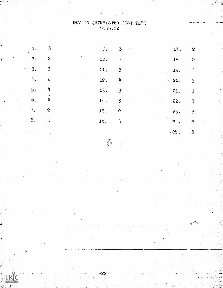
KEY PO UINMESPER POST TEST9055.02
1. 3 17. 2
2. 2 10. 3 18. 2
3. 3 11. 3 19. 3
4. 2 12. 4 , 20. 3
5. 4 13. 3 21. 1
6. 4 14. 3 22. 3
7. 2 15. 2 23. 3
8. 3 16. 3 24. 2
25. 3
-22-