Document number: 72.120 - Fluenta · 5.2.5 IS-Barrier; Intrinsic Safety Barrier Module The...
13
Document number: 72.120.304 Document title: FGM 160 Functional Description Scope: ISO 9001:2008 §7.2.3 Additional Information (when applicable) B 2013.01.25 Removed from User Manual, update of contents, graphics and layout MKJ KH - MW MW A 2007.11.28 Issued for Fluenta release, moved to User Manual MS TM N/A AAJ Rev. index Issue date Reason for issue Author Review Review Review by QA Approved Replacement for: Total pages: 13 Fluenta source doc. (for translations):
Transcript of Document number: 72.120 - Fluenta · 5.2.5 IS-Barrier; Intrinsic Safety Barrier Module The...

Document number: 72.120.304 Document title: FGM 160 Functional Description
Scope: ISO 9001:2008 §7.2.3
Additional Information (when applicable)
B 2013.01.25 Removed from User Manual, update of contents, graphics and layout
MKJ KH - MW MW
A 2007.11.28 Issued for Fluenta release, moved to User Manual
MS TM N/A AAJ
Rev. index
Issue date Reason for issue Author Review Review Review by QA
Approved
Replacement for: Total pages:
13 Fluenta source doc. (for translations):
FGM 160 Functional Description
72.120.304 Page 2 of 13
TABLE OF CONTENTS
1. Purpose ............................................................................................................ 4
2. Abbreviations .................................................................................................... 4
3. General ............................................................................................................ 4
3.1 Reference Conditions ................................................................................... 4
3.2 Units of Measurement .................................................................................. 4
3.3 Language.................................................................................................... 4
4. General Technical Descriptions ............................................................................ 4
4.1 Challenges Involved in Flaregas Metering........................................................ 4
4.2 General Description of FGM 160 ..................................................................... 5
4.3 Detailed Explanation of the Measurement Signals ............................................ 7
4.3.1 Continuous Wave (CW) Measurements ................................................... 8
4.3.2 Chirp Measurements ............................................................................ 8
5. Field Computer Unit ........................................................................................... 9
5.1 General ...................................................................................................... 9
5.2 Field Computer Description ........................................................................... 9
5.2.1 DSP; Digital Signal Processing ............................................................10
5.2.2 AFE; Analog Front End .......................................................................10
5.2.3 P&T; Pressure & Temperature .............................................................10
5.2.4 I/O; Input/Output .............................................................................10
5.2.5 IS-Barrier; Intrinsic Safety Barrier Module ...........................................10
5.3 Operating the Field Computer .......................................................................11
5.3.1 Operator Console ................................................................................11
5.3.2 Remote Console .................................................................................11
5.4 Input Signals..............................................................................................11
5.4.1 Transit Time Input Signal ...................................................................11
5.4.2 Pressure Input Signal ........................................................................11
5.4.3 Temperature Input Signal ..................................................................12
5.5 Output Signals ...........................................................................................12
5.5.1 Pulse/Frequency Output .....................................................................12
5.5.2 Analog 4-20mA Output Signals ...........................................................12
5.5.3 HART Output ....................................................................................12
5.5.4 Modbus Serial Interface .....................................................................12
5.5.5 Foundation Fieldbus Interface .............................................................13
6. Ultrasonic Transducers ..................................................................................... 13
6.1 Transducer Full Size (TFS) ...........................................................................13
6.2 Transducer Full Size, Ball Valves ...................................................................13
FGM 160 Functional Description
72.120.304 Page 3 of 13
TABLE OF FIGURES
Figure 1: The FGM 160 system with one pair of ultrasonic sensors. .................. 5
Figure 2: Transit time measurement principle. ............................................... 6
Figure 3: Continuous Wave (CW) signal (burst). ............................................. 8
Figure 4: Chirp signal, with a varying frequency and a fixed amplitude. ............ 8
Figure 5: FGM 160 Field Computer. .............................................................. 9
FGM 160 Functional Description
72.120.304 Page 4 of 13
1. PURPOSE
This document describes the Fluenta Flare Gas meter, FGM 160. The main
components in the system are described and the measuring techniques are explained.
2. ABBREVIATIONS
FGM Flare Gas Meter TFS Transducer Full Size
TCV Transducer Compact Version
3. GENERAL
3.1 Reference Conditions
The following reference conditions are used as a basis: Pressure: 1.01325 bar a
Temperature: 15 °C = 288.15 K
3.2 Units of Measurement
The following units of measurement are used in the FGM 160:
Measurement SI U.S.
Length mm in
Area m2 ft2
Volume m3 or Sm3 MMCF or MMSCF
Mass kg lb
Volume flow rate m3/h or Sm3/h MMCFD or MMSCFD
Mass flow rate kg/h lb/h
Density kg/m3
Pressure (absolute) bar a psi
Temperature °C F
3.3 Language
The FGM 160 is supplied with English text as standard.
4. GENERAL TECHNICAL DESCRIPTIONS
4.1 Challenges Involved in Flaregas Metering
Challenges that must be overcome in order to measure flare gas are among others:
Large velocity variations for the gas flowing in the flare pipe.
FGM 160 Functional Description
72.120.304 Page 5 of 13
Large pipe diameters. Low pressure situation at the metering point.
Field-mounted sensor shall operate in explosive or potentially explosive areas, thus limited power is available.
The FGM 160 is designed to operate under these difficult conditions and the capability to do so is verified by instruments present in operation. The ultrasonic sensors are wetted but non-intrusive, and will thus not disturb the flowing gas.
The meter has no mechanical moving parts, which makes the instrument less exposed to wear.
The problem associated with high flow velocities is, among others, that the gas flowing in the pipe is a source of noise, which reduces the recognizability of the transmitted, ultrasonic signal. Also, high gas velocities will carry the ultrasonic
pulses along the pipe, which makes it even more difficult for the sensors to communicate.
Low pressures, large pipe diameters and limitations of the amount of electric power that can be applied due to explosive area regulations, are all factors that increase the difficulty while obtaining good measurements. These problems are
solved by using two different types of signals, Continuous Wave and Chirp. This measurement technique is described further in this document.
4.2 General Description of FGM 160
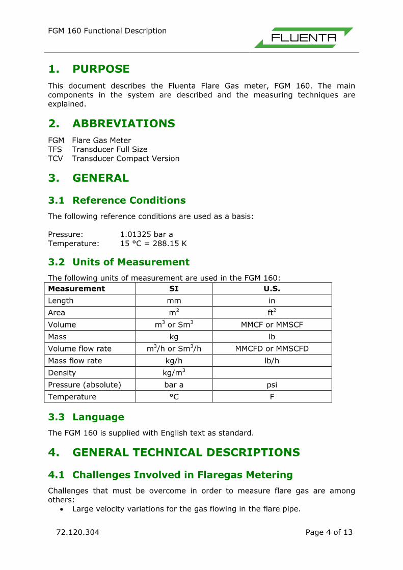
The FGM 160 system consists of a Field Computer and a transducer pair. Transducers are ultrasonic sensors mounted on the flare gas pipes, ref. .
Figure 1: The FGM 160 system with one pair of ultrasonic sensors.
The FGM 160 measures the gas velocity by using the time of flight technique, which means that the ultrasonic transducers communicate with each other by
transmitting and receiving ultrasonic signals.
FGM 160 Functional Description
72.120.304 Page 6 of 13
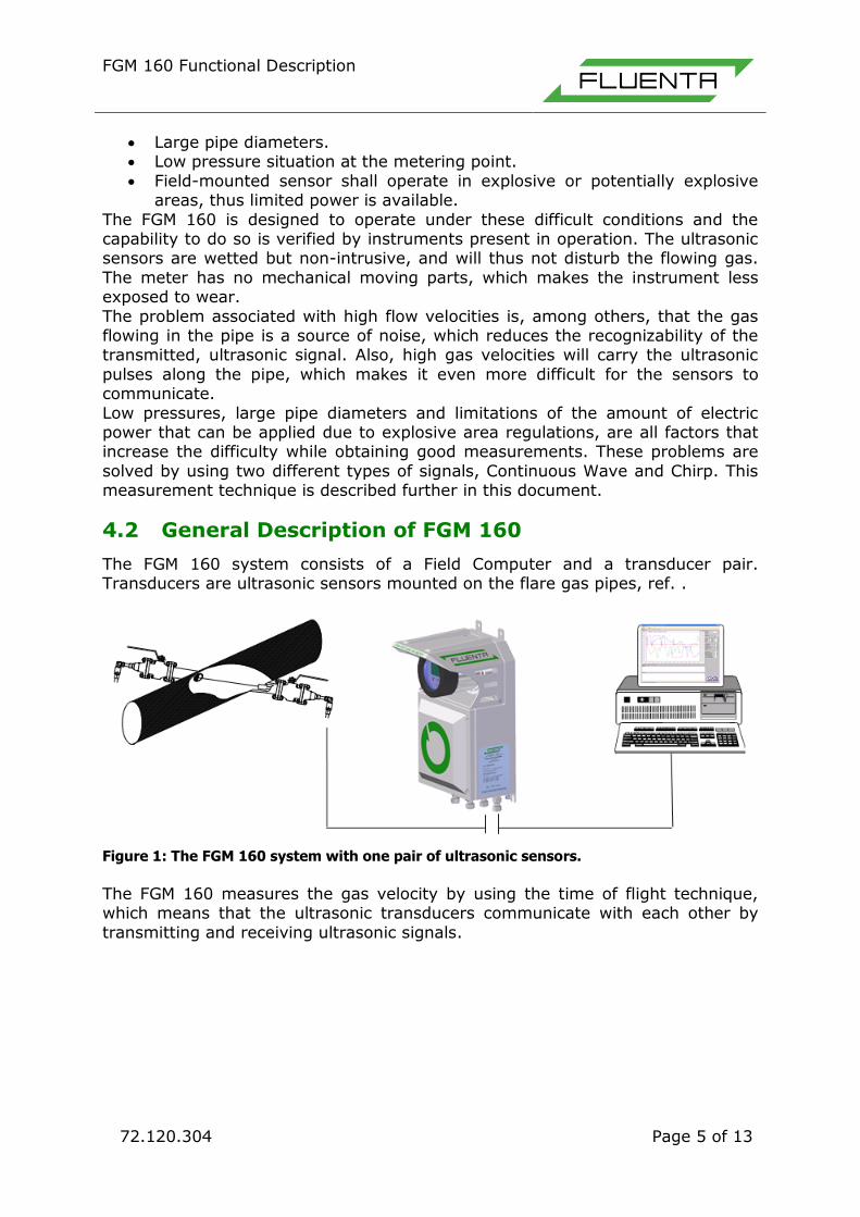
Figure 2: Transit time measurement principle.
With reference to
Figure 2, the measurement principle may be explained as follows:
Both transducers transmit and receive ultrasonic pulses and the difference in
transit time between the downstream pulse (from A to B) and the upstream pulse (from B to A) is measured. When gas is flowing in the pipe, a pulse
travelling against the stream (upstream) will take longer time to reach the opposite transducer than a pulse travelling with the flow (downstream). This time the difference is used to calculate the velocity of the flowing medium by the
following equation:

FGM 160 Functional Description
72.120.304 Page 7 of 13
2112
1221
cos2 tt
ttL
where:
= axial velocity of flowing medium without compensation for Reynolds
Number variation
L = distance between transducer tips
= angle of intertransducer centre line to axis of pipe
12t = transit time (sec) from Transducer (A) to Transducer (B)
(downstream)
21t = transit time (sec) from Transducer (B) to Transducer (A) (upstream)
4.3 Detailed Explanation of the Measurement Signals
As outlined in section 4.2, the measurement principle is based on the transit time difference. This section gives a more detailed description of the signal types used
to perform the measurements. Two different signal types are used, and the combination of these two makes the FGM 160 a unique instrument for flare gas
measurement purposes. The two signal types used are: CW - Continuous Wave (Signal burst)
Chirp - Variable frequency signal
FGM 160 Functional Description
72.120.304 Page 8 of 13
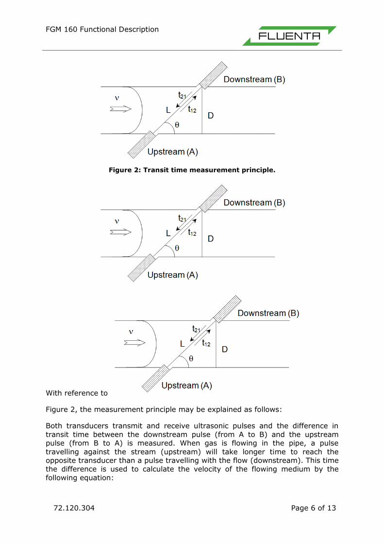
4.3.1 Continuous Wave (CW) Measurements
This CW signal has a constant frequency and amplitude as illustrated in Error! eference source not found..
Figure 3: Continuous Wave (CW) signal (burst).
This is a general signal type used in ultrasonic instruments. When measuring flare gases at high velocities, the medium in the pipe line will generate significant
acoustic noise. This acoustic noise may have equal or higher amplitude than the CW signal, which makes detection difficult, or even impossible. This signal is therefore only suitable for measurements at low gas flow velocities.
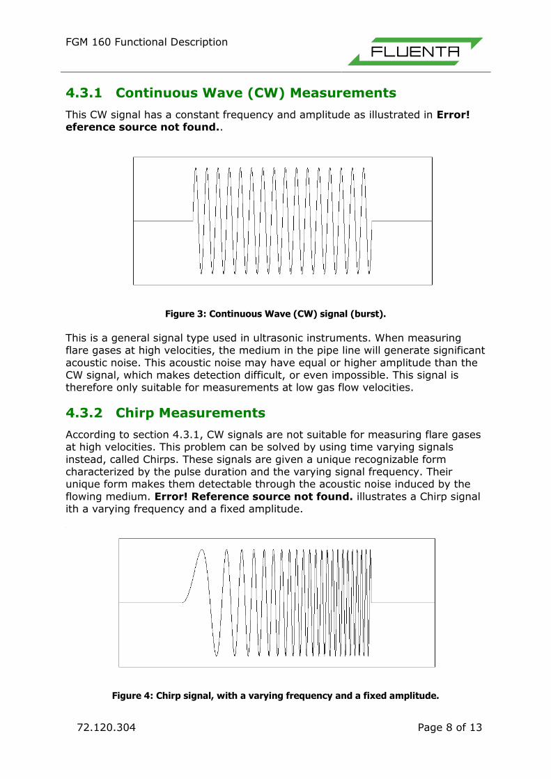
4.3.2 Chirp Measurements
According to section 4.3.1, CW signals are not suitable for measuring flare gases at high velocities. This problem can be solved by using time varying signals
instead, called Chirps. These signals are given a unique recognizable form characterized by the pulse duration and the varying signal frequency. Their unique form makes them detectable through the acoustic noise induced by the
flowing medium. Error! Reference source not found. illustrates a Chirp signal ith a varying frequency and a fixed amplitude.
Figure 4: Chirp signal, with a varying frequency and a fixed amplitude.

FGM 160 Functional Description
72.120.304 Page 9 of 13
Chirp signals are used in combination with CW signals for measuring flare gases
at low velocities. At higher velocities the instrument utilizes only Chirp signals. The combination of Chirp and CW at low velocities enhances the accuracy of the
FGM 160 measurements for these velocities.
5. FIELD COMPUTER UNIT
5.1 General
The processing of the information from the transducers and from the pressure
and temperature transmitters is performed in the FGM 160. The Field Computer controls the transmission to and detection of signals from the transducers and
performs the critical transit time measurements. The Field Computer also performs calculations based on the time measurement results and presents data and alarm messages.
5.2 Field Computer Description
The FGM 160 Unit, shown in Figure 5, consists of two enclosures, the EEx-d enclosure and the EEx-e enclosure. The EEx-d enclosure contains the computer
unit and all the system electronics. The computer unit and the electronics form a stack, with defined and distributed tasks. A distributed system will be more
flexible with respect to future expansions and modifications, as the total processing load for the system can be divided on several modules. Thus, the danger of overloading a single CPU unit is reduced.
The PCB stack module can be divided into five main components or units. A Local Display has been standard for the FGM 160 since 2007, completing the PCB stack
with a total of 6 boards.
Figure 5: FGM 160 Field Computer.
FGM 160 Functional Description
72.120.304 Page 10 of 13
5.2.1 DSP; Digital Signal Processing
The Digital Signal Processing unit is the system master. The DSP unit generates the measurement signals and controls the measurement sequences. It collects
data from other module registers and performs flow calculations based on this data. All calculated parameters are stored in defined registers and made
available for the DCS system and the Operator & Service Console through the I/O unit.
5.2.2 AFE; Analog Front End
The Analog Front End unit is the interface between the DSP unit and the ultrasonic transducer sensors via the IS-Barrier unit. At the AFE unit, measurement signals are multiplexed and switched between CW and Chirp
signals, and upstream and downstream direction.
5.2.3 P&T; Pressure & Temperature
The Pressure & Temperature unit collects pressure and temperature information
from external sensors via 4-20 mA current loop or HART interface. All pressure and temperature data are stored in predefined registers available for the DSP unit. Thus, the DSP unit can retrieve P&T parameters in a minimum of time.
5.2.4 I/O; Input/Output
The Input/Output unit is the interface between the FGM 160 in hazardous area and equipment in safe area. At the I/O unit, 24 VDC supply voltage is converted
to the required operational voltages for other units in the stack. Furthermore, all signals and communication to and from the DCS system and Operator & Service
Console are handled by this unit.
5.2.5 IS-Barrier; Intrinsic Safety Barrier Module
The Intrinsic Safety Barrier Module ensures the intrinsic safety to the ultrasonic sensors mounted in hazardous areas. The total energy is kept within safe limits
to prevent explosions due to excessive heat. In addition, the IS-Barrier unit includes safety barriers for the P&T transmitters. Thus, P&T transmitters with “Ex
i” certification can be interfaced directly to the FC I. The EEx-e enclosure is a junction/connection box. It houses the necessary terminal blocks and is the physical link between the FGM 160 and the
transducers. All communication wiring provided by the FGM 160 and power supply goes via this enclosure.
The entire EEx-d solution will be available on request. The EEx-e housing is then removed, and the terminal blocks and the FGM 160 Unit are integrated in a common EEx-d housing.
FGM 160 Functional Description
72.120.304 Page 11 of 13
5.3 Operating the Field Computer
5.3.1 Operator Console
Operating the FGM 160 from an Operator Console connects from the FC I via a
Modbus RS485 connection. According to the RS485 standard, the Operator Console can be located up to 1200 meters away from the FC I. A DCS system via Modbus RS422 or RS485 gives access to basic parameters and limited system
management. The interface is based on entering commands with corresponding values. These
commands are predefined and described in detail in the User‟s Manual. The corresponding value can be either a new parameter value or only a display value telling the FGM 160 to display a certain parameter or result.
5.3.2 Remote Console
An option for a NetOp server is available if needed. NetOp is a Remote Control Software that gives access to the Operator/Service Console through a TCP/IP
connection. A NetOp server installed locally in the Service Console enables full access to the system for operators off-site with a NetOp client if access is approved on-site.
This solution eliminates the demand for on-site Operator/Service Control since full access and system control is available from any location.
This solution also makes it possible for Fluenta AS to remote the system, assist with diagnostics and offer online software updates and support. Software updates for DSP, P&T and I/O can be upgraded on-the-fly.
A RS 485 to TCP/IP converter enables Fluenta AS to assist with diagnostics and support, but control of the system is not possible with this solution.
5.4 Input Signals
5.4.1 Transit Time Input Signal
The ultrasonic transducer pair supplies the FGM 160 with upstream and downstream transit time measurements, ref. section 4.2. These measurements
in combination with the pressure and temperature measurements, described in section 5.4.2 and 5.4.3, form the foundation for the FGM 160 outputs described in section 5.5.
5.4.2 Pressure Input Signal
The pressure measurement is performed close to the transducers to get the correct pressure at the measuring point. The pressure measurement point is
downstream the transducers relative to flow measurement. The pressure input signal is either in form of a 2-wire 4-20 mA signal or through HART transmitter modem. The locally mounted transmitter is either powered by
the 24 VDC power supply in the FGM 160, or by an external source.
FGM 160 Functional Description
72.120.304 Page 12 of 13
5.4.3 Temperature Input Signal
The temperature probe is installed furthest away (downstream) from the measuring point to limit the effect of potential turbulence.
The FGM 160 collects data from the temperature transmitter through a 4-20 mA or HART interface. The temperature transmitter is connected to the FGM 160 by
2-wire configuration. The locally mounted temperature transmitter is powered in the same manner as the pressure transmitter. The pressure transmitter and the temperature transmitter are connected to the
FGM 160 through internal barriers in the FGM 160 Field Computer. The analogue inputs are realized as floating 20 ohm resistors, through which the loop current
flows. The common mode voltage range is within -10 to +24 volts with respect to the FGM 160‟s ground level.
5.5 Output Signals
5.5.1 Pulse/Frequency Output
The FGM 160 has 3 pulse output channels that can e.g. be configured for totalizing of mass and volume. Two of these pulse output channels can be configured as frequency output
channels with a frequency range from 10Hz to 4 kHz. These outputs can be configured e.g. for a mass or volume flow rate.
5.5.2 Analog 4-20mA Output Signals
The FGM 160 has six analog 4-20 mA output channels. Each of the six output channels can be configured to one of the following parameters:
Standard Volume Flow rate Actual Volume Flow rate Mass Flow rate
Density (Standard Conditions) Density (Actual)
Molecular Weight Pressure Temperature
Alarm = 4 mA (Alarm LOW) Alarm = 20 mA (Alarm HIGH)
Analog outputs are disabled in FGM 160 Foundation Fieldbus configuration.
5.5.3 HART Output
The FGM 160 has one analog output channel that can be configured as a HART output interface. The HART output interface supports function code 0, 1 and 3.
Refer to Fluenta AS doc. no.: 72.120.306 – FGM 160 HART Interface Specification, for a detailed description of the HART interface.
5.5.4 Modbus Serial Interface
Parameters in the FGM 160 are accessible through a serial interface by using the Modbus protocol. All or just a selected range of parameters in an array can be

FGM 160 Functional Description
72.120.304 Page 13 of 13
accessed in a single read or write operation. Single precision floating-point presentation is the implemented format. Some arrays contain „Read only‟
parameters. Others contain „Read / Write‟ parameters. Refer to Fluenta AS doc. no. 72.120.305 – FGM 160 Modbus Interface
Specification for a full description of the Modbus interface. Modbus DCS communication is disabled in FGM 160 Foundation Fieldbus configuration.
5.5.5 Foundation Fieldbus Interface
Maximum 4 parameters can be predefined according to customer requirement. List of parameters available for the customer can be found in Fluenta AS doc. no.
72.120.305 (all parameters available when using Modbus Serial Interface are also accessible when using Foundation Fieldbus output).
6. ULTRASONIC TRANSDUCERS
6.1 Transducer Full Size (TFS)
The ultrasonic transducers mounted onto the flare pipe are approved for operation in Zone 0 with safety class EEx ia IIC T6. They are mounted in
transducer holders that are welded onto the flare pipe at carefully selected angles, positioned with specially designed mounting jigs.
A piezo-electric crystal is mounted inside the titanium housing at the front of the transducer. When the crystal is subjected to an alternating electrical signal, it vibrates with the same frequency as the electrical signal. The crystal is attached
to the front membrane of the titanium housing and this membrane vibrates with the crystal. The membrane movement generates the ultrasonic signals. When a
transducer receives ultrasonic signals, the membrane vibrates and the crystal transfers this movement into an electrical signal. Both transducers in a pair operate as transmitter and receiver. At the
transmitting transducer, an electrical frequency signal is converted to an ultrasonic pulse. At the receiving transducer, the signal is converted back to an
electrical frequency signal, enabling the system to determine the time of travel for the ultrasonic pulse using cross correlation. The measured transit times are used to calculate the axial gas flow velocity and volume flow rate in the pipeline.
6.2 Transducer Full Size, Ball Valves
Ball valves are mounted between the full-size transducer and holder to enable installation and retraction of the transducers during normal process operation.
The pressure sealing is established using a tube fitting solution which, after initial installation, ensures that the transducer position remains constant even after the transducer has been taken out for servicing.