Document No. SES1101213 PPT 001,Rev - My Committeesmycommittees.api.org/standards/ecs/sc8/Meeting...
77
API 4F Design Study: ASD‐89 to LRFD‐05 Mike Effenberger, P.E Sathish Ramamoorthy, Ph.D., P.E. June, 2012; PN 1101213 Preliminary subject to QA check Document No. SES1101213‐PPT‐001,Rev.0a
-
Upload
phunghuong -
Category
Documents
-
view
216 -
download
2
Transcript of Document No. SES1101213 PPT 001,Rev - My Committeesmycommittees.api.org/standards/ecs/sc8/Meeting...
API 4F Design Study: ASD‐89 to LRFD‐05
Mike Effenberger, P.ESathish Ramamoorthy, Ph.D., P.E.June, 2012; PN 1101213
Preliminary subject to QA check
Document No. SES1101213‐PPT‐001,Rev.0a
2
Contents
• API 4F Work • Background• Objectives• Design Study‐Methodology• Model Details• AISC‐05 Analysis Specifications• Rig 1 Design Study Results Detailed Design Results
• Rig 3 Design Study Results Detailed Design Results
3
API 4F
• API Funded Study – Check Effect of Load Factors for Drilling Structures• Paper – Code Conversion Issues Going From ASD to LRFD – Draft Provided
– Comments Due June 24• First Study Meeting – 2‐22‐2012
API 4F Work Group– Mark Trevithick (T&T Engineering) – Chair– Anthony Mannering (Precision Drilling)– Marcus McCoo (NOV)– Paul Landis (Lee C Moore)
First Load Factors – ASCE7 Models Received (last): 03/05/2012 Finish Work Date: 11/05/2012

4
API 4F Design Study‐Status6‐13‐2012
• Paper – Issued as Draft (Close 6-24-2012) Issue to API End of June• Rig 1 Boot-Strap Mast – Complete (Pending Review)
ASD-89 (StruCAD & SAP) ASD-05 – 1st Order & ASD-05- P-Delta LRFD-05
• Rig 3 Derrick ASD-89 & LRFD-05
• Rig 2 Mast & Substructure In progress – Duplicate Plate Element Issues (Removed)
• Rig 4 Dual Derrick – Duplicate Element Issue (Merging Elements)• Rig 5 Workover – Staad Model – Transfer Issues (Working with
Designer)
5
Background
• API 4F, Specification for Drilling and Well Servicing Structures states requirements and gives recommendations for suitable steel
structures for drilling and well‐servicing operations API 4F specifies the steel structures to be designed in accordance with
Allowable Stress Design/Elastic design per AISC 335‐89
• API 4F committee is interested in going from the Allowable Stress Design to the latest strength design Allowable Strength Design (ASD)/Load and Resistance Factor Design (LRFD) provision in AISC 360‐05 specification.
• Latest AISC specification is AISC 360‐10. The 2010 edition supersedes and is an update of the 2005 edition. The 2010 edition is yet to be supported by Computer Programs.
6
Background
• In the LRFD design methodology, design results are affected by the load factors selected for the individual loads (self weight, hook load, and environmental loads) For building design, load factors and load combinations are
specified in ASCE 7, Minimum Design Loads for Buildings and Other Structures
• The load factors are generally estimated using the statistical data for the individual loads and reliability concepts Statistical data for Hook load is not readily available. Therefore,
the load factors given in ASCE 7‐05 will be used for the design study (first case evaluation)
7
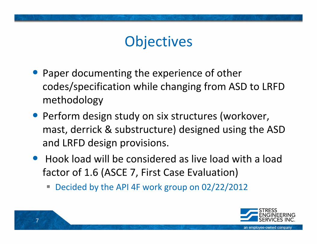
Objectives
• Paper documenting the experience of other codes/specification while changing from ASD to LRFD methodology
• Perform design study on six structures (workover, mast, derrick & substructure) designed using the ASD and LRFD design provisions.
• Hook load will be considered as live load with a load factor of 1.6 (ASCE 7, First Case Evaluation) Decided by the API 4F work group on 02/22/2012
8
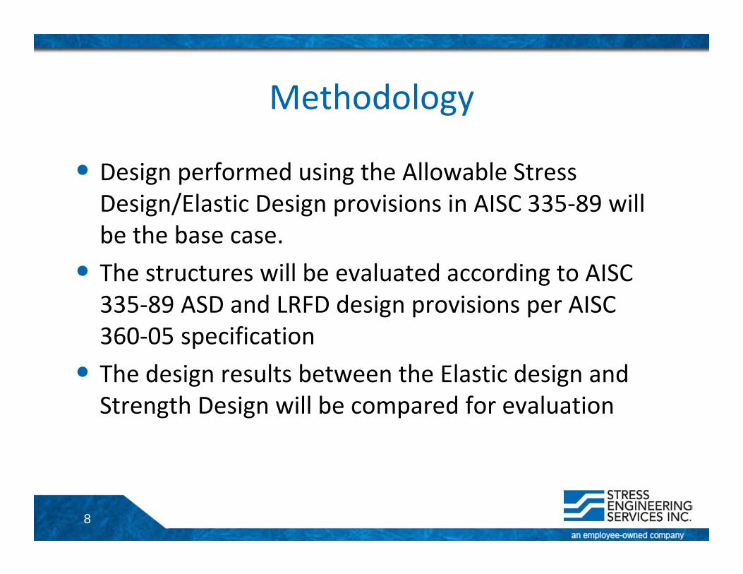
Methodology
• Design performed using the Allowable Stress Design/Elastic Design provisions in AISC 335‐89 will be the base case.
• The structures will be evaluated according to AISC 335‐89 ASD and LRFD design provisions per AISC 360‐05 specification
• The design results between the Elastic design and Strength Design will be compared for evaluation
9
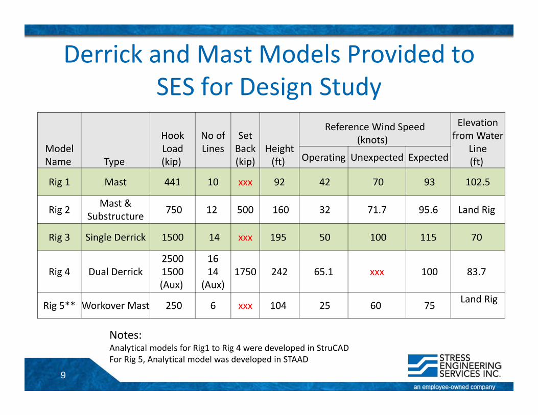
Derrick and Mast Models Provided to SES for Design Study
Model Name Type
Hook Load(kip)
No of Lines
SetBack(kip)
Height (ft)
Reference Wind Speed (knots)
Elevation from Water
Line(ft)Operating Unexpected Expected
Rig 1 Mast 441 10 xxx 92 42 70 93 102.5
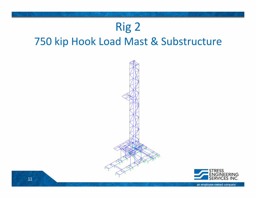
Rig 2 Mast & Substructure 750 12 500 160 32 71.7 95.6 Land Rig
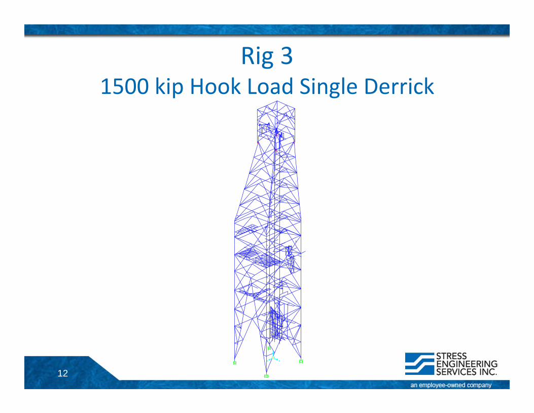
Rig 3 Single Derrick 1500 14 xxx 195 50 100 115 70
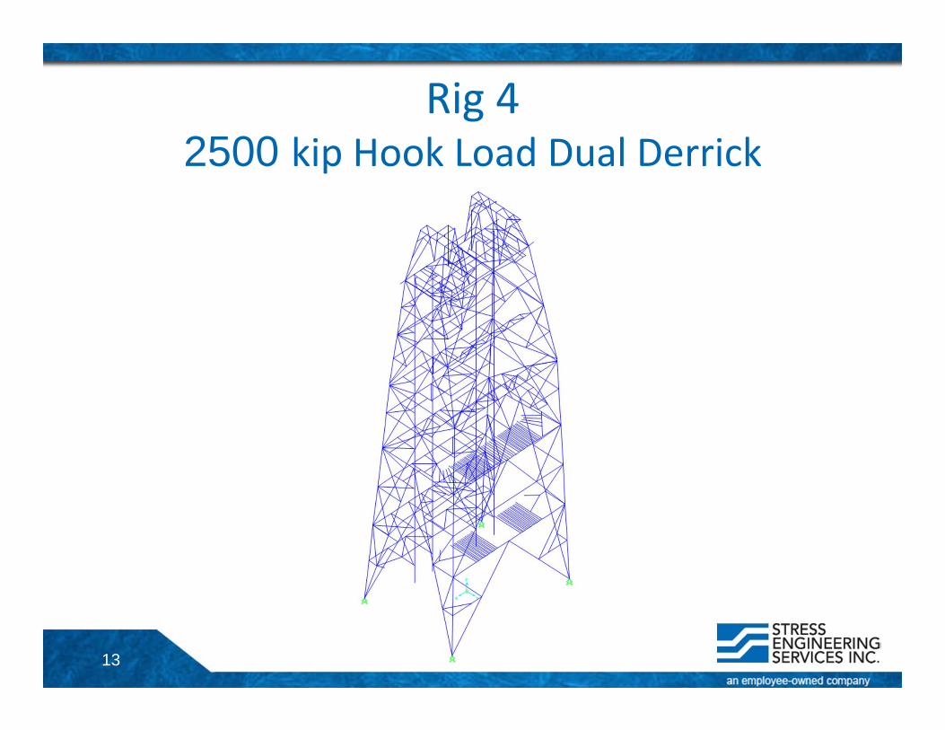
Rig 4 Dual Derrick25001500(Aux)
1614
(Aux)1750 242 65.1 xxx 100 83.7
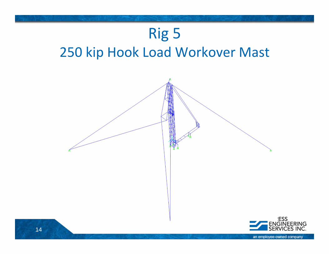
Rig 5** Workover Mast 250 6 xxx 104 25 60 75 Land Rig
Notes:Analytical models for Rig1 to Rig 4 were developed in StruCADFor Rig 5, Analytical model was developed in STAAD
10
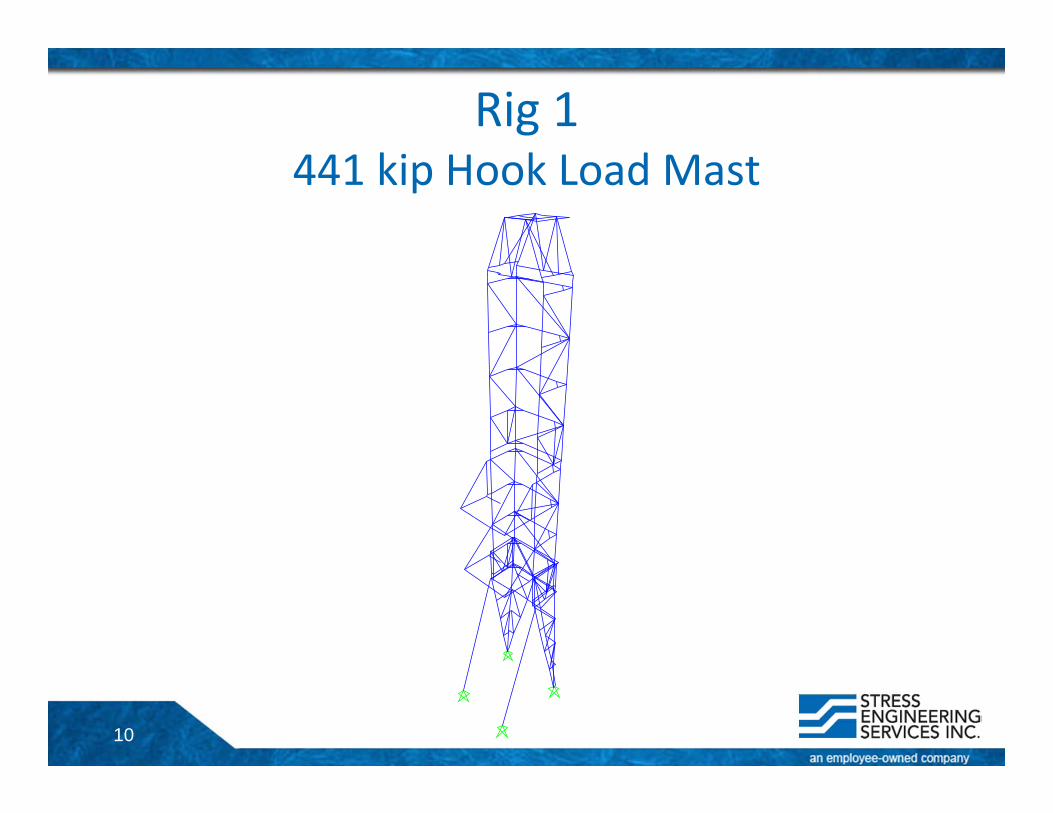
Rig 1441 kip Hook Load Mast
11
Rig 2750 kip Hook Load Mast & Substructure
Y
Z
X
Z
X Y
12
Rig 31500 kip Hook Load Single Derrick
X
Z
Y
Z
X Y
13
Rig 42500 kip Hook Load Dual Derrick
14
Rig 5250 kip Hook Load Workover Mast
15
Software Details
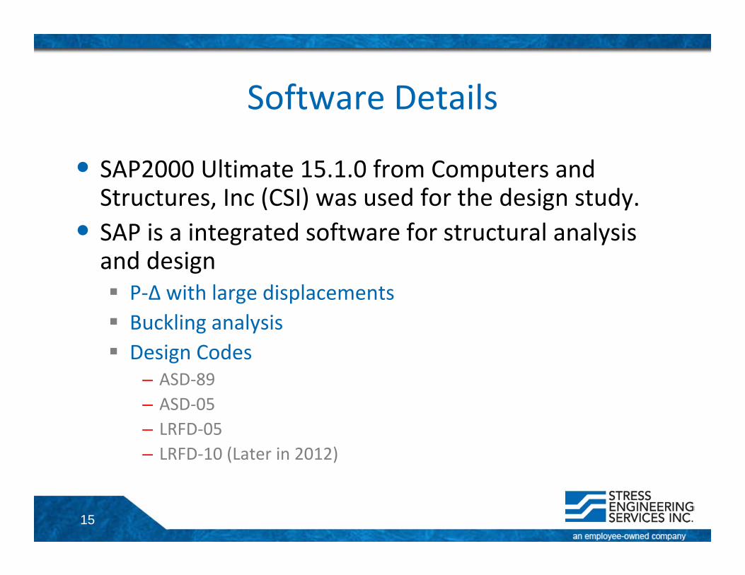
• SAP2000 Ultimate 15.1.0 from Computers and Structures, Inc (CSI) was used for the design study.
• SAP is a integrated software for structural analysis and design P‐Δ with large displacements Buckling analysis Design Codes
– ASD‐89– ASD‐05– LRFD‐05– LRFD‐10 (Later in 2012)
16
StruCAD to SAP2000 Conversion
• StruCAD models were imported in SAP. The imported models were compared with the StruCAD models.
• In general, most of the model features are imported without any issues. However, there are few StruCAD commands/features that are not imported in SAP. These are manually edited in the imported model.
• SAP technical support and development team were notified about the import issues.
17
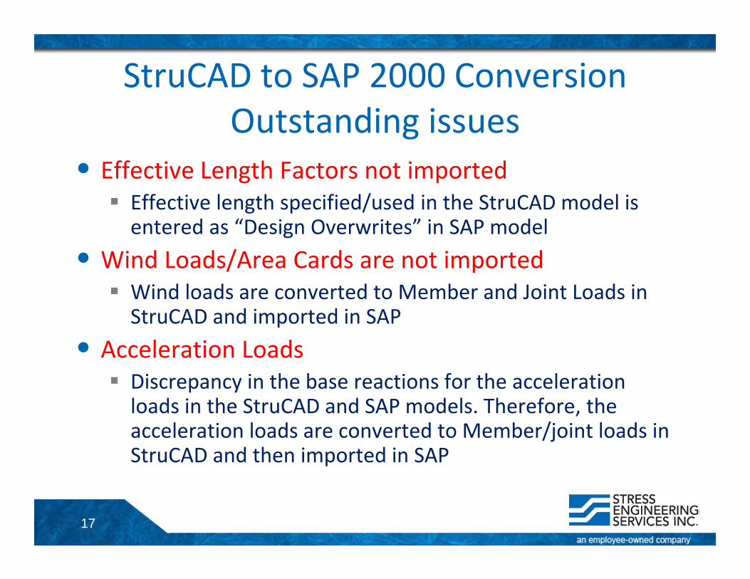
StruCAD to SAP 2000 ConversionOutstanding issues
• Effective Length Factors not imported Effective length specified/used in the StruCAD model is entered as “Design Overwrites” in SAP model
• Wind Loads/Area Cards are not imported Wind loads are converted to Member and Joint Loads in StruCAD and imported in SAP
• Acceleration Loads Discrepancy in the base reactions for the acceleration loads in the StruCAD and SAP models. Therefore, the acceleration loads are converted to Member/joint loads in StruCAD and then imported in SAP
18
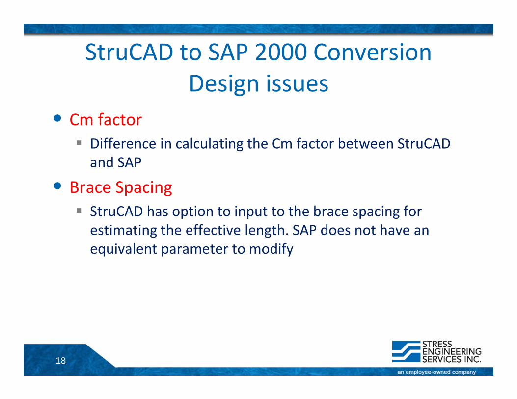
StruCAD to SAP 2000 ConversionDesign issues
• Cm factor Difference in calculating the Cm factor between StruCAD and SAP
• Brace Spacing StruCAD has option to input to the brace spacing for estimating the effective length. SAP does not have an equivalent parameter to modify
19
Design Basis
• AISC‐1989 Specification Allowable Stress Design (ASD‐89)
• AISC‐2005 Specification Load and Resistance Factor Design (LRFD‐05)
20
Design BasisAllowable Stress Design‐89
• The imported models were run in SAP and compared with the StruCAD results In general, the member forces are comparable to the StruCAD member forces. For some members, there is a small discrepancy in the minor and major axis moments.
• Allowable Stress Design (ASD‐89)– Static linear analysis– With 1/3rd increase in allowable stress for expected and
unexpected load case
21
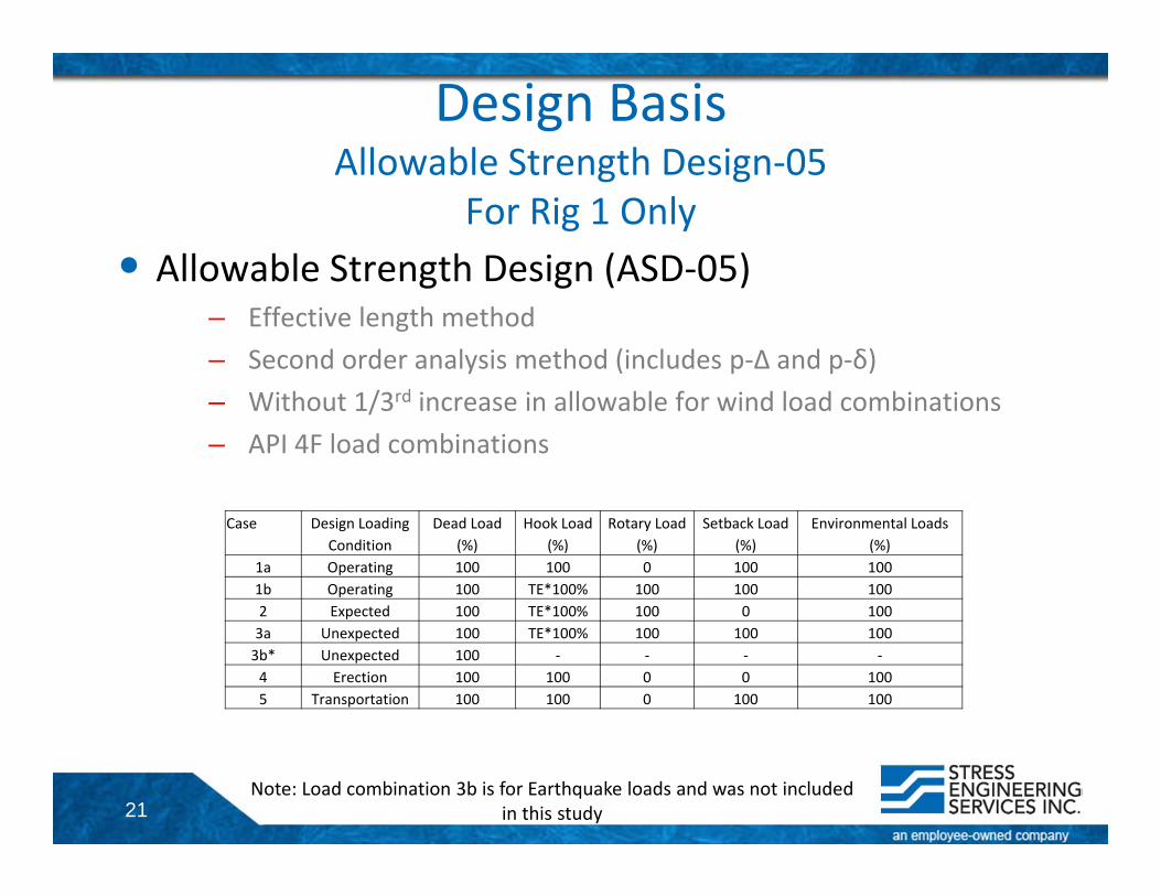
Design BasisAllowable Strength Design‐05
For Rig 1 Only• Allowable Strength Design (ASD‐05)
– Effective length method– Second order analysis method (includes p‐Δ and p‐δ)– Without 1/3rd increase in allowable for wind load combinations– API 4F load combinations
Case Design Loading Dead Load Hook Load Rotary Load Setback Load Environmental LoadsCondition (%) (%) (%) (%) (%)
1a Operating 100 100 0 100 1001b Operating 100 TE*100% 100 100 1002 Expected 100 TE*100% 100 0 1003a Unexpected 100 TE*100% 100 100 1003b* Unexpected 100 ‐ ‐ ‐ ‐4 Erection 100 100 0 0 1005 Transportation 100 100 0 100 100
Note: Load combination 3b is for Earthquake loads and was not included in this study
22
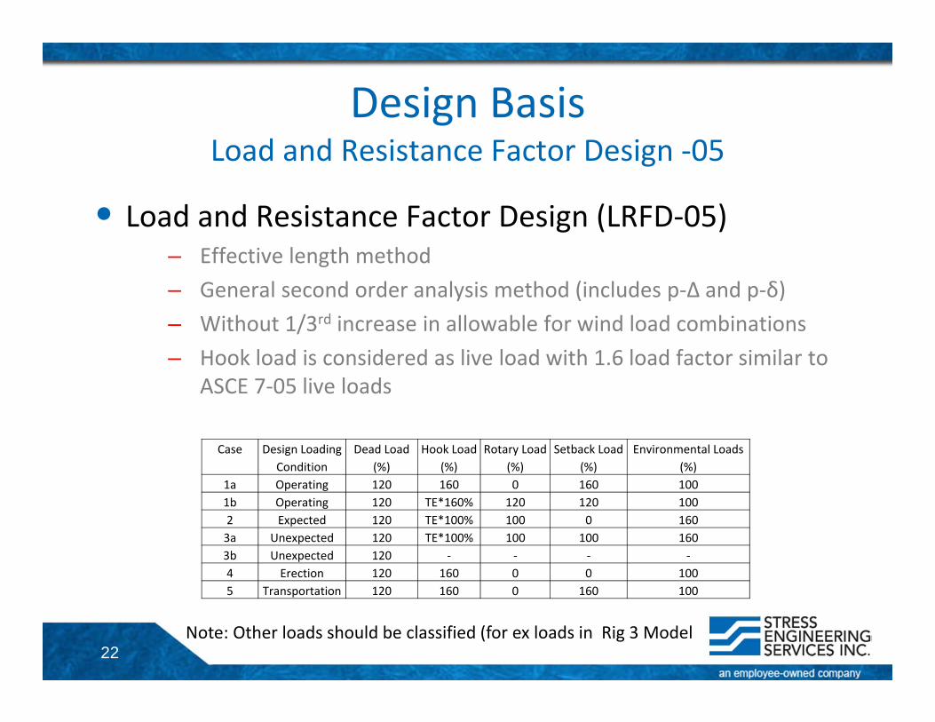
Design BasisLoad and Resistance Factor Design ‐05
• Load and Resistance Factor Design (LRFD‐05)– Effective length method– General second order analysis method (includes p‐Δ and p‐δ)– Without 1/3rd increase in allowable for wind load combinations– Hook load is considered as live load with 1.6 load factor similar to
ASCE 7‐05 live loads
Case Design Loading Dead Load Hook Load Rotary Load Setback Load Environmental LoadsCondition (%) (%) (%) (%) (%)
1a Operating 120 160 0 160 1001b Operating 120 TE*160% 120 120 1002 Expected 120 TE*100% 100 0 1603a Unexpected 120 TE*100% 100 100 1603b Unexpected 120 ‐ ‐ ‐ ‐4 Erection 120 160 0 0 1005 Transportation 120 160 0 160 100
Note: Other loads should be classified (for ex loads in Rig 3 Model
23
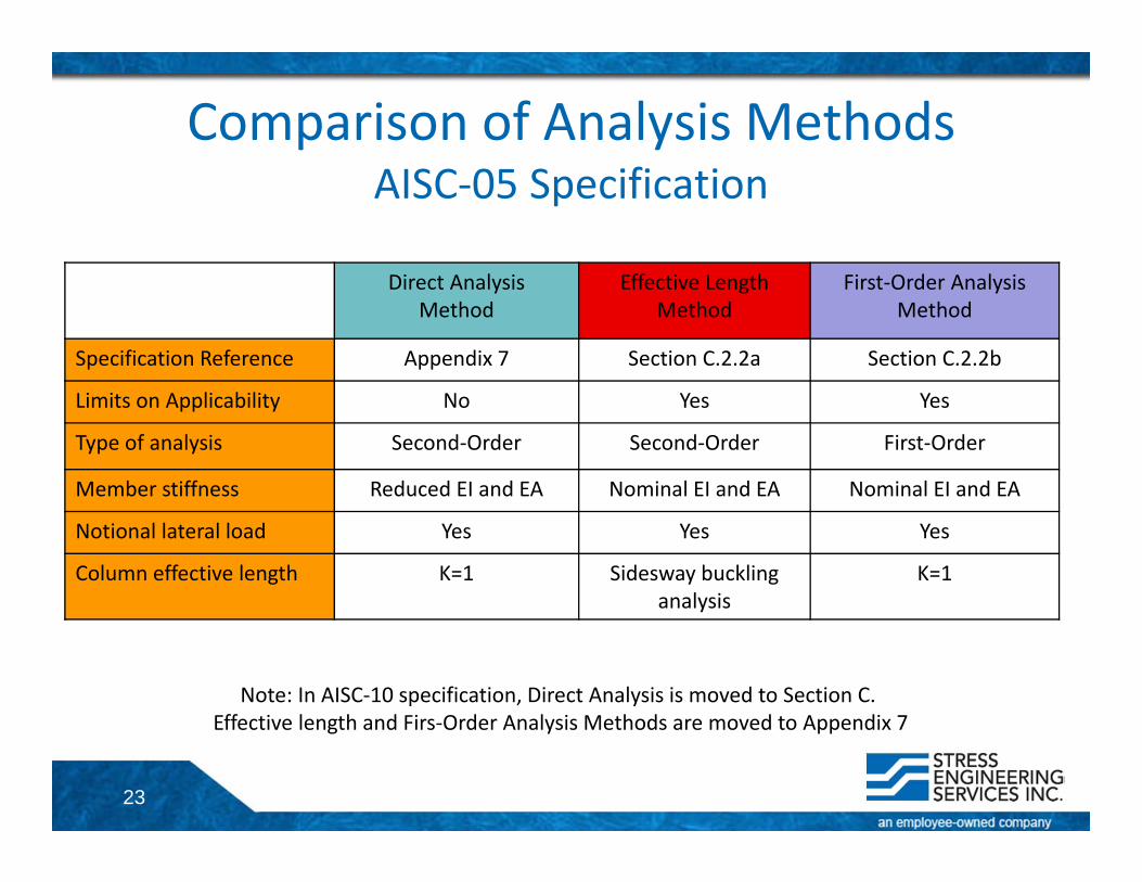
Comparison of Analysis MethodsAISC‐05 Specification
Direct Analysis Method
Effective Length Method
First‐Order Analysis Method
Specification Reference Appendix 7 Section C.2.2a Section C.2.2b
Limits on Applicability No Yes Yes
Type of analysis Second‐Order Second‐Order First‐Order
Member stiffness Reduced EI and EA Nominal EI and EA Nominal EI and EA
Notional lateral load Yes Yes Yes
Column effective length K=1 Sidesway buckling analysis
K=1
Note: In AISC‐10 specification, Direct Analysis is moved to Section C. Effective length and Firs‐Order Analysis Methods are moved to Appendix 7
24
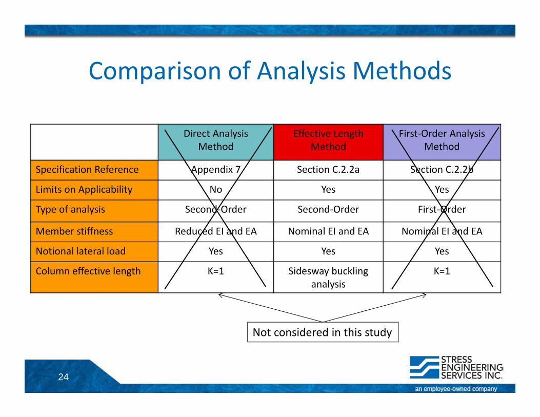
Comparison of Analysis Methods
Direct Analysis Method
Effective Length Method
First‐Order Analysis Method
Specification Reference Appendix 7 Section C.2.2a Section C.2.2b
Limits on Applicability No Yes Yes
Type of analysis Second‐Order Second‐Order First‐Order
Member stiffness Reduced EI and EA Nominal EI and EA Nominal EI and EA
Notional lateral load Yes Yes Yes
Column effective length K=1 Sidesway buckling analysis
K=1
Not considered in this study
25
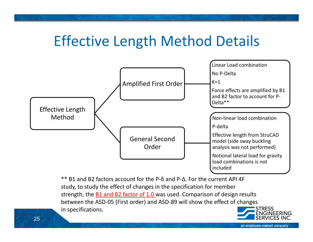
Effective Length Method Details
Effective Length Method
Amplified First Order
Linear Load combinationNo P‐DeltaK=1Force effects are amplified by B1 and B2 factor to account for P‐Delta**
General Second Order
Non‐linear load combinationP‐deltaEffective length from StruCAD model (side sway buckling analysis was not performed)Notional lateral load for gravity load combinations is not included
** B1 and B2 factors account for the P‐δ and P‐Δ. For the current API 4F study, to study the effect of changes in the specification for member strength, the B1 and B2 factor of 1.0 was used. Comparison of design results between the ASD‐05 (First order) and ASD‐89 will show the effect of changes in specifications.
26
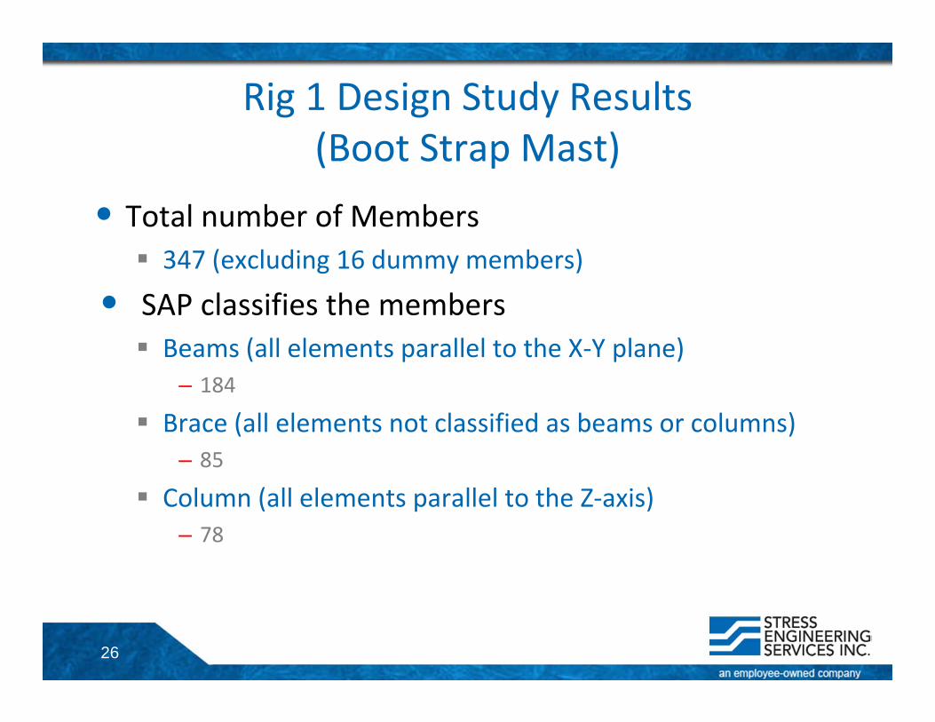
Rig 1 Design Study Results(Boot Strap Mast)
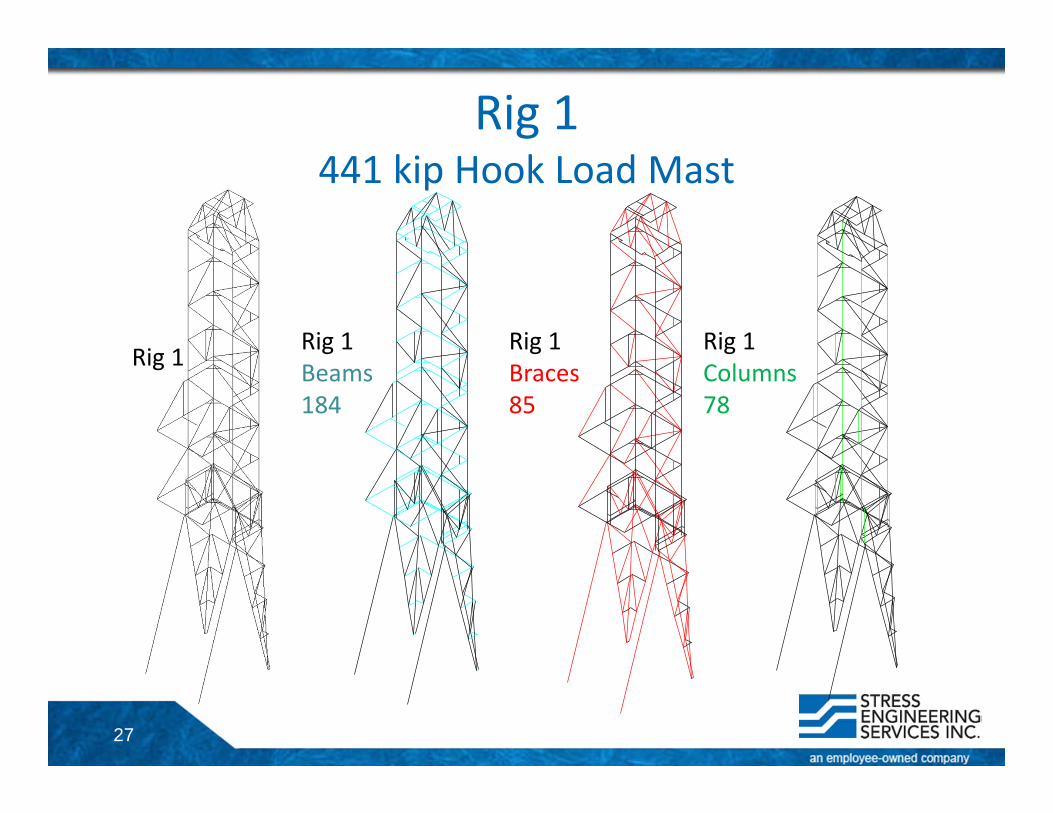
• Total number of Members 347 (excluding 16 dummy members)
• SAP classifies the members Beams (all elements parallel to the X‐Y plane)
– 184
Brace (all elements not classified as beams or columns)– 85
Column (all elements parallel to the Z‐axis)– 78
27
Rig 1441 kip Hook Load Mast
Rig 1 Rig 1Beams184
Rig 1Braces85
Rig 1Columns78
28
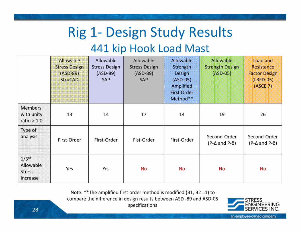
Rig 1‐ Design Study Results441 kip Hook Load Mast
Allowable Stress Design (ASD‐89) StruCAD
Allowable Stress Design (ASD‐89)
SAP
Allowable Stress Design (ASD‐89)
SAP
Allowable Strength Design (ASD‐05)Amplified First Order Method**
Allowable Strength Design
(ASD‐05)
Load and Resistance
Factor Design(LRFD‐05)(ASCE 7)
Members with unity ratio > 1.0
13 14 17 14 19 26
Type of analysis
First‐Order First‐Order Fist‐Order First‐Order Second‐Order(P‐Δ and P‐δ)
Second‐Order(P‐Δ and P‐δ)
1/3rdAllowable Stress Increase
Yes Yes No No No No
Note: **The amplified first order method is modified (B1, B2 =1) to compare the difference in design results between ASD ‐89 and ASD‐05
specifications
29
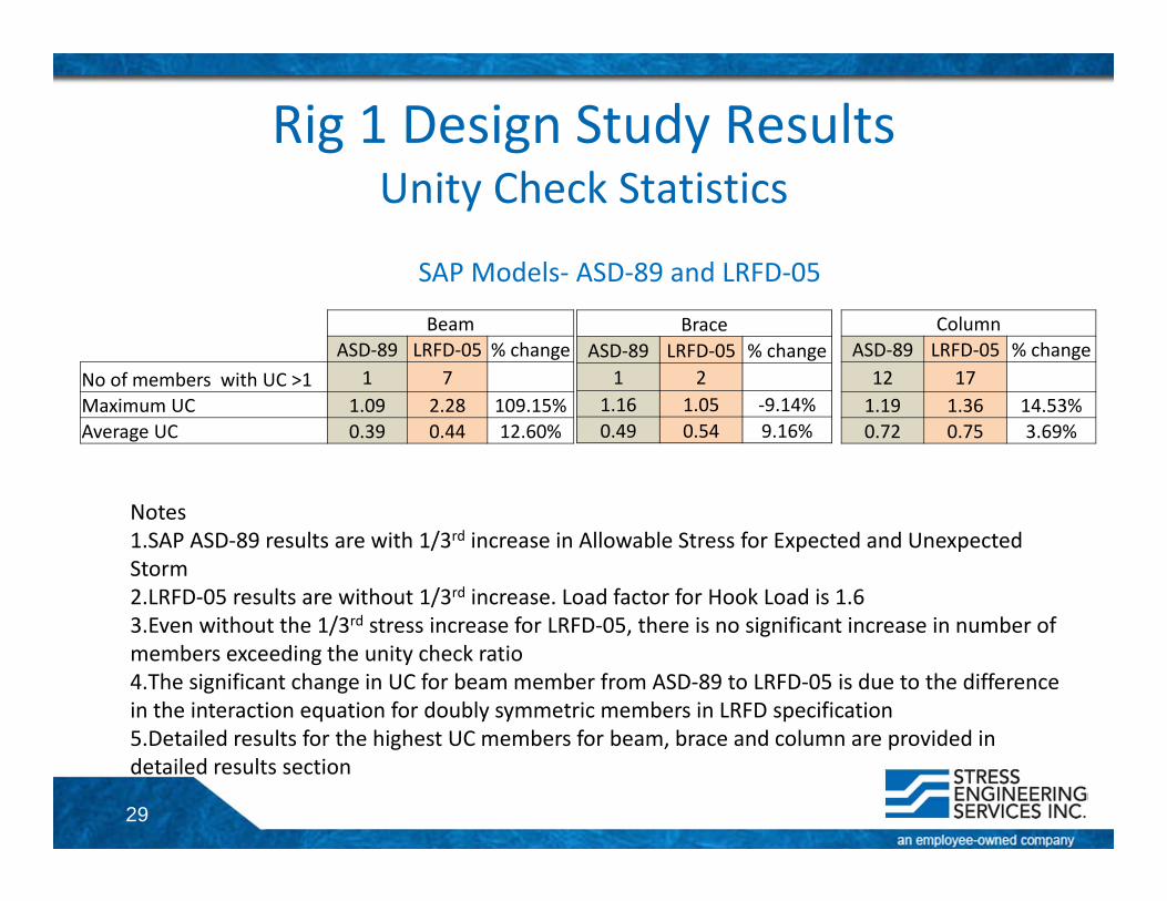
Rig 1 Design Study ResultsUnity Check Statistics
BeamASD‐89 LRFD‐05 % change
No of members with UC >1 1 7Maximum UC 1.09 2.28 109.15%Average UC 0.39 0.44 12.60%
BraceASD‐89 LRFD‐05 % change
1 21.16 1.05 ‐9.14%0.49 0.54 9.16%
ColumnASD‐89 LRFD‐05 % change12 171.19 1.36 14.53%0.72 0.75 3.69%
Notes1.SAP ASD‐89 results are with 1/3rd increase in Allowable Stress for Expected and Unexpected Storm2.LRFD‐05 results are without 1/3rd increase. Load factor for Hook Load is 1.63.Even without the 1/3rd stress increase for LRFD‐05, there is no significant increase in number of members exceeding the unity check ratio4.The significant change in UC for beam member from ASD‐89 to LRFD‐05 is due to the difference in the interaction equation for doubly symmetric members in LRFD specification 5.Detailed results for the highest UC members for beam, brace and column are provided in detailed results section
SAP Models‐ ASD‐89 and LRFD‐05
30
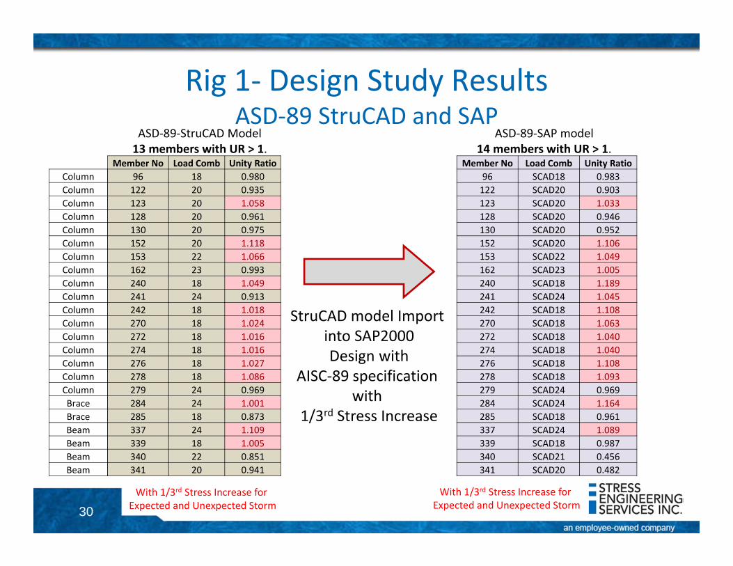
Rig 1‐ Design Study ResultsASD‐89 StruCAD and SAP
ASD‐89‐StruCAD Model13 members with UR > 1.
With 1/3rd Stress Increase for Expected and Unexpected Storm
With 1/3rd Stress Increase for Expected and Unexpected Storm
StruCAD model Import into SAP2000Design with
AISC‐89 specification with
1/3rd Stress Increase
ASD‐89‐SAP model14 members with UR > 1.
Member No Load Comb Unity Ratio96 18 0.980122 20 0.935123 20 1.058128 20 0.961130 20 0.975152 20 1.118153 22 1.066162 23 0.993240 18 1.049241 24 0.913242 18 1.018270 18 1.024272 18 1.016274 18 1.016276 18 1.027278 18 1.086279 24 0.969284 24 1.001285 18 0.873337 24 1.109339 18 1.005340 22 0.851341 20 0.941
Member No Load Comb Unity Ratio96 SCAD18 0.983122 SCAD20 0.903123 SCAD20 1.033128 SCAD20 0.946130 SCAD20 0.952152 SCAD20 1.106153 SCAD22 1.049162 SCAD23 1.005240 SCAD18 1.189241 SCAD24 1.045242 SCAD18 1.108270 SCAD18 1.063272 SCAD18 1.040274 SCAD18 1.040276 SCAD18 1.108278 SCAD18 1.093279 SCAD24 0.969284 SCAD24 1.164285 SCAD18 0.961337 SCAD24 1.089339 SCAD18 0.987340 SCAD21 0.456341 SCAD20 0.482
ColumnColumnColumnColumnColumnColumnColumnColumnColumnColumnColumnColumnColumnColumnColumnColumnColumnBraceBraceBeamBeamBeamBeam
31
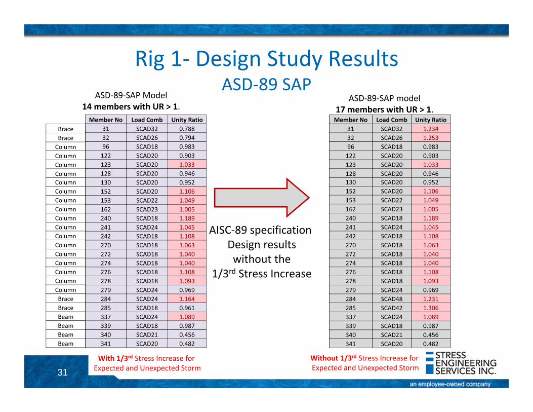
Rig 1‐ Design Study ResultsASD‐89 SAP
ASD‐89‐SAP Model14 members with UR > 1.
With 1/3rd Stress Increase for Expected and Unexpected Storm
Without 1/3rd Stress Increase for Expected and Unexpected Storm
AISC‐89 specification Design resultswithout the
1/3rd Stress Increase
ASD‐89‐SAP model17 members with UR > 1.
Member No Load Comb Unity Ratio31 SCAD32 0.78832 SCAD26 0.79496 SCAD18 0.983122 SCAD20 0.903123 SCAD20 1.033128 SCAD20 0.946130 SCAD20 0.952152 SCAD20 1.106153 SCAD22 1.049162 SCAD23 1.005240 SCAD18 1.189241 SCAD24 1.045242 SCAD18 1.108270 SCAD18 1.063272 SCAD18 1.040274 SCAD18 1.040276 SCAD18 1.108278 SCAD18 1.093279 SCAD24 0.969284 SCAD24 1.164285 SCAD18 0.961337 SCAD24 1.089339 SCAD18 0.987340 SCAD21 0.456341 SCAD20 0.482
Member No Load Comb Unity Ratio31 SCAD32 1.23432 SCAD26 1.25396 SCAD18 0.983122 SCAD20 0.903123 SCAD20 1.033128 SCAD20 0.946130 SCAD20 0.952152 SCAD20 1.106153 SCAD22 1.049162 SCAD23 1.005240 SCAD18 1.189241 SCAD24 1.045242 SCAD18 1.108270 SCAD18 1.063272 SCAD18 1.040274 SCAD18 1.040276 SCAD18 1.108278 SCAD18 1.093279 SCAD24 0.969284 SCAD48 1.231285 SCAD42 1.306337 SCAD24 1.089339 SCAD18 0.987340 SCAD21 0.456341 SCAD20 0.482
BraceBraceColumnColumnColumnColumnColumnColumnColumnColumnColumnColumnColumnColumnColumnColumnColumnColumnColumnBraceBraceBeamBeamBeamBeam
32
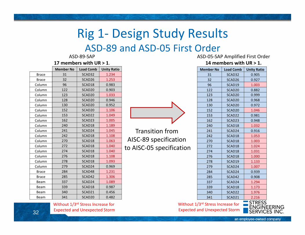
Rig 1‐ Design Study ResultsASD‐89 and ASD‐05 First Order
ASD‐89‐SAP17 members with UR > 1.
ASD‐05‐SAP Amplified First Order14 members with UR > 1.
Without 1/3rd Stress Increase for Expected and Unexpected Storm
Without 1/3rd Stress Increase for Expected and Unexpected Storm
Transition from AISC‐89 specification to AISC‐05 specification
Member No Load Comb Unity Ratio31 SCAD32 1.23432 SCAD26 1.25396 SCAD18 0.983122 SCAD20 0.903123 SCAD20 1.033128 SCAD20 0.946130 SCAD20 0.952152 SCAD20 1.106153 SCAD22 1.049162 SCAD23 1.005240 SCAD18 1.189241 SCAD24 1.045242 SCAD18 1.108270 SCAD18 1.063272 SCAD18 1.040274 SCAD18 1.040276 SCAD18 1.108278 SCAD18 1.093279 SCAD24 0.969284 SCAD48 1.231285 SCAD42 1.306337 SCAD24 1.089339 SCAD18 0.987340 SCAD21 0.456341 SCAD20 0.482
BraceBraceColumnColumnColumnColumnColumnColumnColumnColumnColumnColumnColumnColumnColumnColumnColumnColumnColumnBraceBraceBeamBeamBeamBeam
Member No Load Comb Unity Ratio31 SCAD32 0.90532 SCAD26 0.92796 SCAD19 1.003122 SCAD20 0.882123 SCAD20 0.999128 SCAD20 0.968130 SCAD20 0.972152 SCAD20 1.046153 SCAD22 0.981162 SCAD23 0.948240 SCAD18 1.032241 SCAD24 0.916242 SCAD18 1.053270 SCAD18 1.003272 SCAD18 1.024274 SCAD18 1.031276 SCAD18 1.000278 SCAD19 1.133279 SCAD24 1.007284 SCAD24 0.939285 SCAD42 0.908337 SCAD24 1.294339 SCAD18 1.173340 SCAD22 1.976341 SCAD21 2.216
33
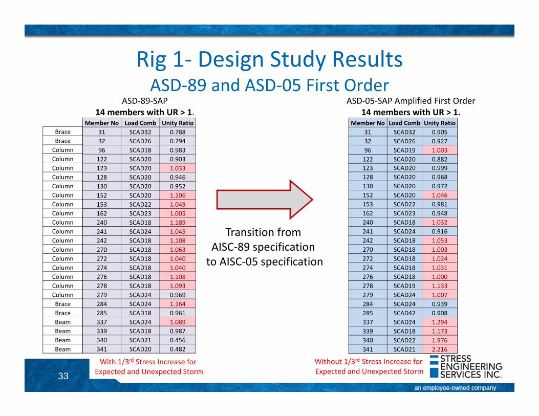
Rig 1‐ Design Study ResultsASD‐89 and ASD‐05 First Order
ASD‐89‐SAP14 members with UR > 1.
ASD‐05‐SAP Amplified First Order14 members with UR > 1.
With 1/3rd Stress Increase for Expected and Unexpected Storm
Without 1/3rd Stress Increase for Expected and Unexpected Storm
Transition from AISC‐89 specification to AISC‐05 specification
Member No Load Comb Unity Ratio31 SCAD32 0.78832 SCAD26 0.79496 SCAD18 0.983122 SCAD20 0.903123 SCAD20 1.033128 SCAD20 0.946130 SCAD20 0.952152 SCAD20 1.106153 SCAD22 1.049162 SCAD23 1.005240 SCAD18 1.189241 SCAD24 1.045242 SCAD18 1.108270 SCAD18 1.063272 SCAD18 1.040274 SCAD18 1.040276 SCAD18 1.108278 SCAD18 1.093279 SCAD24 0.969284 SCAD24 1.164285 SCAD18 0.961337 SCAD24 1.089339 SCAD18 0.987340 SCAD21 0.456341 SCAD20 0.482
Member No Load Comb Unity Ratio31 SCAD32 0.90532 SCAD26 0.92796 SCAD19 1.003122 SCAD20 0.882123 SCAD20 0.999128 SCAD20 0.968130 SCAD20 0.972152 SCAD20 1.046153 SCAD22 0.981162 SCAD23 0.948240 SCAD18 1.032241 SCAD24 0.916242 SCAD18 1.053270 SCAD18 1.003272 SCAD18 1.024274 SCAD18 1.031276 SCAD18 1.000278 SCAD19 1.133279 SCAD24 1.007284 SCAD24 0.939285 SCAD42 0.908337 SCAD24 1.294339 SCAD18 1.173340 SCAD22 1.976341 SCAD21 2.216
BraceBraceColumnColumnColumnColumnColumnColumnColumnColumnColumnColumnColumnColumnColumnColumnColumnColumnColumnBraceBraceBeamBeamBeamBeam
34
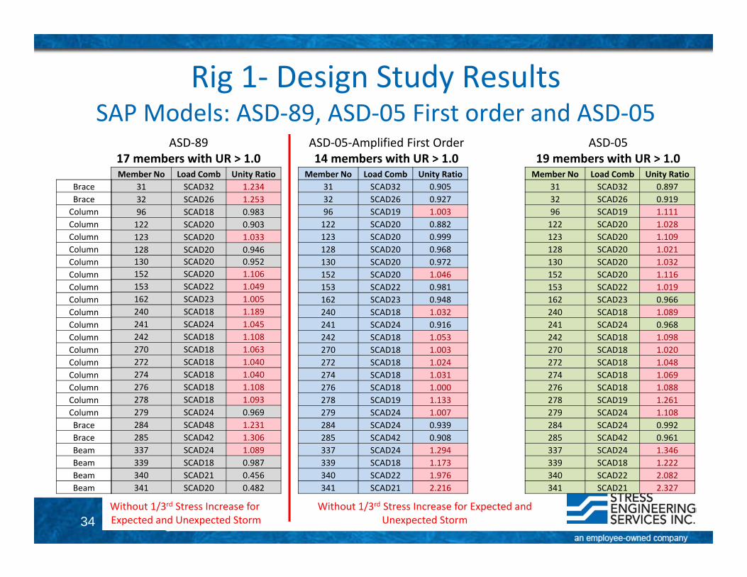
Rig 1‐ Design Study ResultsSAP Models: ASD‐89, ASD‐05 First order and ASD‐05
ASD‐8917 members with UR > 1.0
ASD‐05‐Amplified First Order14 members with UR > 1.0
ASD‐0519 members with UR > 1.0
Without 1/3rd Stress Increase for Expected and Unexpected Storm
Without 1/3rd Stress Increase for Expected and Unexpected Storm
Member No Load Comb Unity Ratio31 SCAD32 1.23432 SCAD26 1.25396 SCAD18 0.983122 SCAD20 0.903123 SCAD20 1.033128 SCAD20 0.946130 SCAD20 0.952152 SCAD20 1.106153 SCAD22 1.049162 SCAD23 1.005240 SCAD18 1.189241 SCAD24 1.045242 SCAD18 1.108270 SCAD18 1.063272 SCAD18 1.040274 SCAD18 1.040276 SCAD18 1.108278 SCAD18 1.093279 SCAD24 0.969284 SCAD48 1.231285 SCAD42 1.306337 SCAD24 1.089339 SCAD18 0.987340 SCAD21 0.456341 SCAD20 0.482
BraceBraceColumnColumnColumnColumnColumnColumnColumnColumnColumnColumnColumnColumnColumnColumnColumnColumnColumnBraceBraceBeamBeamBeamBeam
Member No Load Comb Unity Ratio31 SCAD32 0.90532 SCAD26 0.92796 SCAD19 1.003122 SCAD20 0.882123 SCAD20 0.999128 SCAD20 0.968130 SCAD20 0.972152 SCAD20 1.046153 SCAD22 0.981162 SCAD23 0.948240 SCAD18 1.032241 SCAD24 0.916242 SCAD18 1.053270 SCAD18 1.003272 SCAD18 1.024274 SCAD18 1.031276 SCAD18 1.000278 SCAD19 1.133279 SCAD24 1.007284 SCAD24 0.939285 SCAD42 0.908337 SCAD24 1.294339 SCAD18 1.173340 SCAD22 1.976341 SCAD21 2.216
Member No Load Comb Unity Ratio31 SCAD32 0.89732 SCAD26 0.91996 SCAD19 1.111122 SCAD20 1.028123 SCAD20 1.109128 SCAD20 1.021130 SCAD20 1.032152 SCAD20 1.116153 SCAD22 1.019162 SCAD23 0.966240 SCAD18 1.089241 SCAD24 0.968242 SCAD18 1.098270 SCAD18 1.020272 SCAD18 1.048274 SCAD18 1.069276 SCAD18 1.088278 SCAD19 1.261279 SCAD24 1.108284 SCAD24 0.992285 SCAD42 0.961337 SCAD24 1.346339 SCAD18 1.222340 SCAD22 2.082341 SCAD21 2.327
35
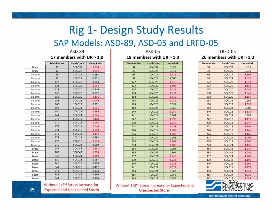
Rig 1‐ Design Study ResultsSAP Models: ASD‐89, ASD‐05 and LRFD‐05
ASD‐8917 members with UR > 1.0
ASD‐0519 members with UR > 1.0
LRFD‐0526 members with UR > 1.0
Without 1/3rd Stress Increase for Expected and Unexpected Storm
Without 1/3rd Stress Increase for Expected and Unexpected Storm
Member No Load Comb Unity Ratio31 SCAD32 1.23432 SCAD26 1.25396 SCAD18 0.98397 SCAD23 0.911122 SCAD20 0.903123 SCAD20 1.033128 SCAD20 0.946130 SCAD20 0.952152 SCAD20 1.106153 SCAD22 1.049160 SCAD23 0.972162 SCAD23 1.005240 SCAD18 1.189241 SCAD24 1.045242 SCAD18 1.108270 SCAD18 1.063272 SCAD18 1.040274 SCAD18 1.040276 SCAD18 1.108277 SCAD24 0.994278 SCAD18 1.093279 SCAD24 0.969284 SCAD48 1.231285 SCAD42 1.306337 SCAD24 1.089339 SCAD18 0.987340 SCAD21 0.456341 SCAD20 0.482342 SCAD48 0.378343 SCAD42 0.399344 SCAD18 0.196
Member No Load Comb Unity Ratio31 SCAD32 0.89732 SCAD26 0.91996 SCAD19 1.11197 SCAD23 1.000122 SCAD20 1.028123 SCAD20 1.109128 SCAD20 1.021130 SCAD20 1.032152 SCAD20 1.116153 SCAD22 1.019160 SCAD23 0.997162 SCAD23 0.966240 SCAD18 1.089241 SCAD24 0.968242 SCAD18 1.098270 SCAD18 1.020272 SCAD18 1.048274 SCAD18 1.069276 SCAD18 1.088277 SCAD24 0.966278 SCAD19 1.261279 SCAD24 1.108284 SCAD24 0.992285 SCAD42 0.961337 SCAD24 1.346339 SCAD18 1.222340 SCAD22 2.082341 SCAD21 2.327354 SCAD24 0.967355 SCAD24 0.965363 SCAD18 0.989
Member No Load Comb Unity Ratio31 SCAD32 0.91132 SCAD26 0.93996 SCAD19 1.19297 SCAD24 1.027122 SCAD20 1.043123 SCAD20 1.135128 SCAD20 1.045130 SCAD20 1.040152 SCAD20 1.157153 SCAD22 0.999160 SCAD23 1.030162 SCAD23 0.980240 SCAD18 1.119241 SCAD24 0.987242 SCAD18 1.117270 SCAD18 1.047272 SCAD18 1.109274 SCAD18 1.146276 SCAD18 1.166277 SCAD24 1.009278 SCAD19 1.361279 SCAD24 1.150284 SCAD48 1.017285 SCAD42 1.058337 SCAD24 1.288339 SCAD42 1.190340 SCAD22 1.990341 SCAD21 2.278354 SCAD24 1.021355 SCAD24 1.020363 SCAD18 1.053
BraceBraceColumnColumnColumnColumnColumnColumnColumnColumnColumnColumnColumnColumnColumnColumnColumnColumnColumnColumnColumnColumnBraceBraceBeamBeamBeamBeamBeamBeamBeam
36
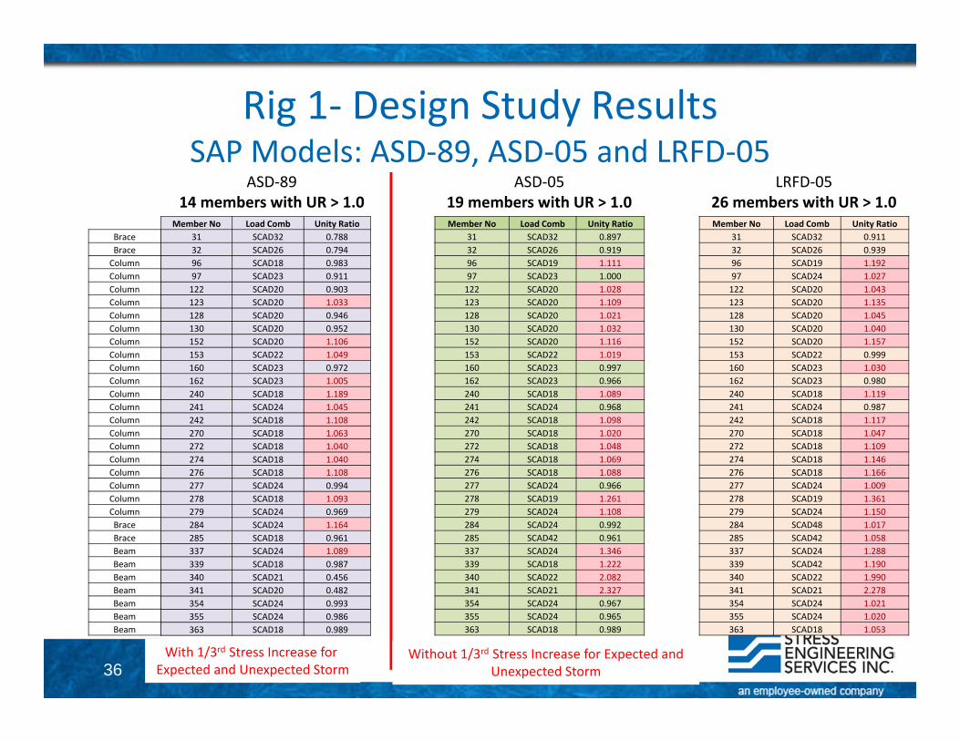
Rig 1‐ Design Study ResultsSAP Models: ASD‐89, ASD‐05 and LRFD‐05
ASD‐8914 members with UR > 1.0
ASD‐0519 members with UR > 1.0
LRFD‐0526 members with UR > 1.0
With 1/3rd Stress Increase for Expected and Unexpected Storm
Without 1/3rd Stress Increase for Expected and Unexpected Storm
Member No Load Comb Unity Ratio31 SCAD32 0.89732 SCAD26 0.91996 SCAD19 1.11197 SCAD23 1.000122 SCAD20 1.028123 SCAD20 1.109128 SCAD20 1.021130 SCAD20 1.032152 SCAD20 1.116153 SCAD22 1.019160 SCAD23 0.997162 SCAD23 0.966240 SCAD18 1.089241 SCAD24 0.968242 SCAD18 1.098270 SCAD18 1.020272 SCAD18 1.048274 SCAD18 1.069276 SCAD18 1.088277 SCAD24 0.966278 SCAD19 1.261279 SCAD24 1.108284 SCAD24 0.992285 SCAD42 0.961337 SCAD24 1.346339 SCAD18 1.222340 SCAD22 2.082341 SCAD21 2.327354 SCAD24 0.967355 SCAD24 0.965363 SCAD18 0.989
Member No Load Comb Unity Ratio31 SCAD32 0.91132 SCAD26 0.93996 SCAD19 1.19297 SCAD24 1.027122 SCAD20 1.043123 SCAD20 1.135128 SCAD20 1.045130 SCAD20 1.040152 SCAD20 1.157153 SCAD22 0.999160 SCAD23 1.030162 SCAD23 0.980240 SCAD18 1.119241 SCAD24 0.987242 SCAD18 1.117270 SCAD18 1.047272 SCAD18 1.109274 SCAD18 1.146276 SCAD18 1.166277 SCAD24 1.009278 SCAD19 1.361279 SCAD24 1.150284 SCAD48 1.017285 SCAD42 1.058337 SCAD24 1.288339 SCAD42 1.190340 SCAD22 1.990341 SCAD21 2.278354 SCAD24 1.021355 SCAD24 1.020363 SCAD18 1.053
BraceBraceColumnColumnColumnColumnColumnColumnColumnColumnColumnColumnColumnColumnColumnColumnColumnColumnColumnColumnColumnColumnBraceBraceBeamBeamBeamBeamBeamBeamBeam
Member No Load Comb Unity Ratio31 SCAD32 0.78832 SCAD26 0.79496 SCAD18 0.98397 SCAD23 0.911122 SCAD20 0.903123 SCAD20 1.033128 SCAD20 0.946130 SCAD20 0.952152 SCAD20 1.106153 SCAD22 1.049160 SCAD23 0.972162 SCAD23 1.005240 SCAD18 1.189241 SCAD24 1.045242 SCAD18 1.108270 SCAD18 1.063272 SCAD18 1.040274 SCAD18 1.040276 SCAD18 1.108277 SCAD24 0.994278 SCAD18 1.093279 SCAD24 0.969284 SCAD24 1.164285 SCAD18 0.961337 SCAD24 1.089339 SCAD18 0.987340 SCAD21 0.456341 SCAD20 0.482354 SCAD24 0.993355 SCAD24 0.986363 SCAD18 0.989

37
Rig 1Detailed Design Results for Selected
Members

38
Rig 1Detailed Design Results for Selected Members• Beam• Brace• Column
39
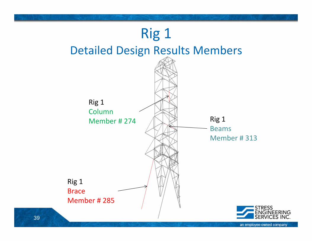
Rig 1 Detailed Design Results Members
Rig 1BeamsMember # 313
Rig 1BraceMember # 285
Rig 1Column Member # 274
40
Rig 1Detailed Design Results for Selected Members• Beam• Brace• Column
41
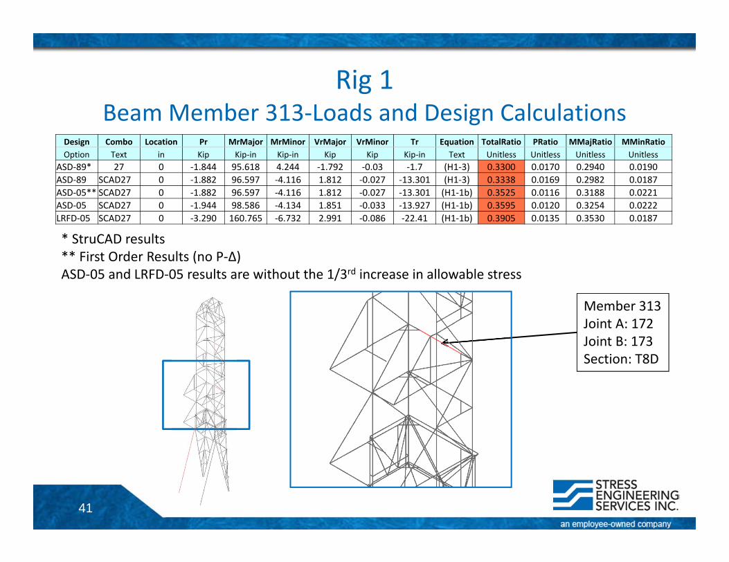
Rig 1Beam Member 313‐Loads and Design Calculations
Design Combo Location Pr MrMajor MrMinor VrMajor VrMinor Tr Equation TotalRatio PRatio MMajRatio MMinRatioOption Text in Kip Kip‐in Kip‐in Kip Kip Kip‐in Text Unitless Unitless Unitless Unitless
ASD‐89* 27 0 ‐1.844 95.618 4.244 ‐1.792 ‐0.03 ‐1.7 (H1‐3) 0.3300 0.0170 0.2940 0.0190ASD‐89 SCAD27 0 ‐1.882 96.597 ‐4.116 1.812 ‐0.027 ‐13.301 (H1‐3) 0.3338 0.0169 0.2982 0.0187ASD‐05** SCAD27 0 ‐1.882 96.597 ‐4.116 1.812 ‐0.027 ‐13.301 (H1‐1b) 0.3525 0.0116 0.3188 0.0221ASD‐05 SCAD27 0 ‐1.944 98.586 ‐4.134 1.851 ‐0.033 ‐13.927 (H1‐1b) 0.3595 0.0120 0.3254 0.0222LRFD‐05 SCAD27 0 ‐3.290 160.765 ‐6.732 2.991 ‐0.086 ‐22.41 (H1‐1b) 0.3905 0.0135 0.3530 0.0187
* StruCAD results** First Order Results (no P‐Δ)ASD‐05 and LRFD‐05 results are without the 1/3rd increase in allowable stress
Member 313Joint A: 172Joint B: 173Section: T8D
42
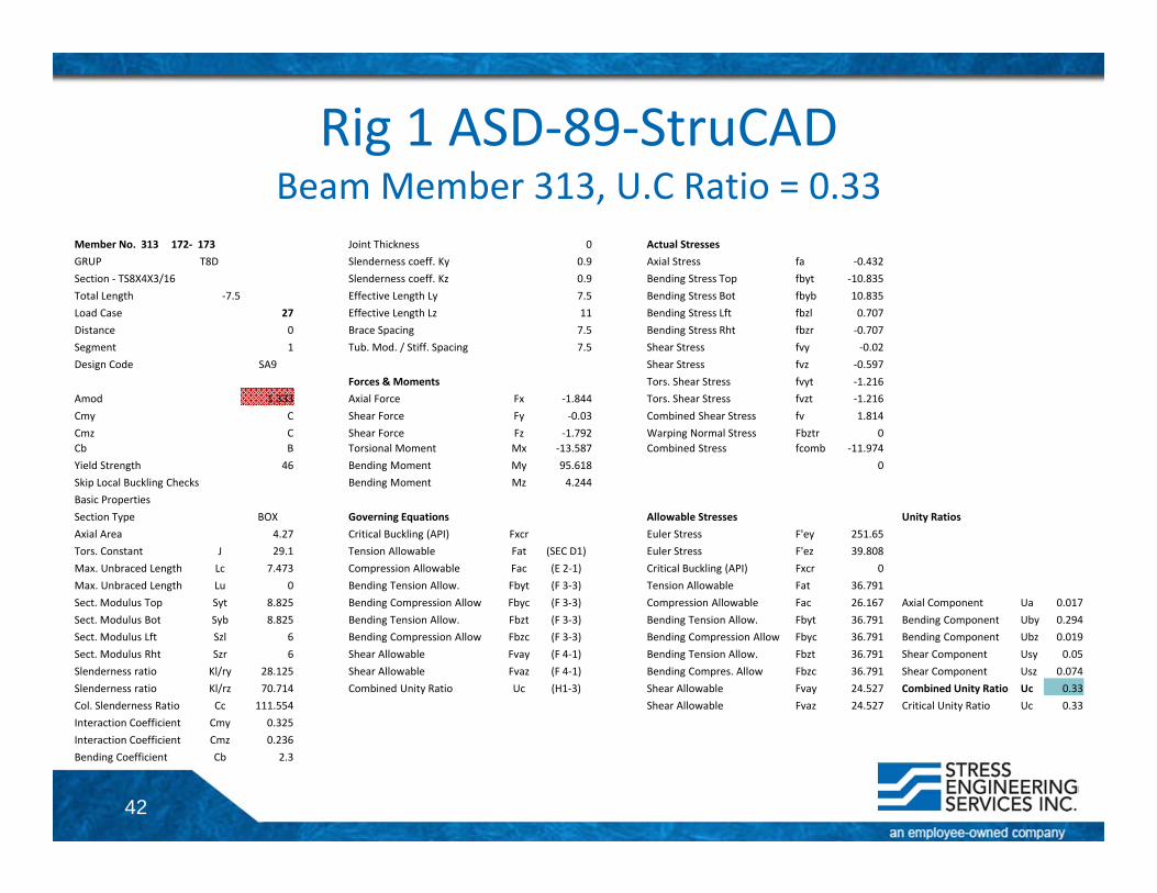
Member No. 313 172‐ 173 Joint Thickness 0 Actual StressesGRUP T8D Slenderness coeff. Ky 0.9 Axial Stress fa ‐0.432Section ‐ TS8X4X3/16 Slenderness coeff. Kz 0.9 Bending Stress Top fbyt ‐10.835Total Length ‐7.5 Effective Length Ly 7.5 Bending Stress Bot fbyb 10.835Load Case 27 Effective Length Lz 11 Bending Stress Lft fbzl 0.707Distance 0 Brace Spacing 7.5 Bending Stress Rht fbzr ‐0.707Segment 1 Tub. Mod. / Stiff. Spacing 7.5 Shear Stress fvy ‐0.02Design Code SA9 Shear Stress fvz ‐0.597
Forces & Moments Tors. Shear Stress fvyt ‐1.216Amod 1.333 Axial Force Fx ‐1.844 Tors. Shear Stress fvzt ‐1.216Cmy C Shear Force Fy ‐0.03 Combined Shear Stress fv 1.814Cmz C Shear Force Fz ‐1.792 Warping Normal Stress Fbztr 0Cb B Torsional Moment Mx ‐13.587 Combined Stress fcomb ‐11.974Yield Strength 46 Bending Moment My 95.618 0Skip Local Buckling Checks Bending Moment Mz 4.244Basic PropertiesSection Type BOX Governing Equations Allowable Stresses Unity RatiosAxial Area 4.27 Critical Buckling (API) Fxcr Euler Stress F'ey 251.65Tors. Constant J 29.1 Tension Allowable Fat (SEC D1) Euler Stress F'ez 39.808Max. Unbraced Length Lc 7.473 Compression Allowable Fac (E 2‐1) Critical Buckling (API) Fxcr 0Max. Unbraced Length Lu 0 Bending Tension Allow. Fbyt (F 3‐3) Tension Allowable Fat 36.791Sect. Modulus Top Syt 8.825 Bending Compression Allow Fbyc (F 3‐3) Compression Allowable Fac 26.167 Axial Component Ua 0.017Sect. Modulus Bot Syb 8.825 Bending Tension Allow. Fbzt (F 3‐3) Bending Tension Allow. Fbyt 36.791 Bending Component Uby 0.294Sect. Modulus Lft Szl 6 Bending Compression Allow Fbzc (F 3‐3) Bending Compression Allow Fbyc 36.791 Bending Component Ubz 0.019Sect. Modulus Rht Szr 6 Shear Allowable Fvay (F 4‐1) Bending Tension Allow. Fbzt 36.791 Shear Component Usy 0.05Slenderness ratio Kl/ry 28.125 Shear Allowable Fvaz (F 4‐1) Bending Compres. Allow Fbzc 36.791 Shear Component Usz 0.074Slenderness ratio Kl/rz 70.714 Combined Unity Ratio Uc (H1‐3) Shear Allowable Fvay 24.527 Combined Unity Ratio Uc 0.33Col. Slenderness Ratio Cc 111.554 Shear Allowable Fvaz 24.527 Critical Unity Ratio Uc 0.33Interaction Coefficient Cmy 0.325Interaction Coefficient Cmz 0.236Bending Coefficient Cb 2.3
Rig 1 ASD‐89‐StruCADBeam Member 313, U.C Ratio = 0.33
43
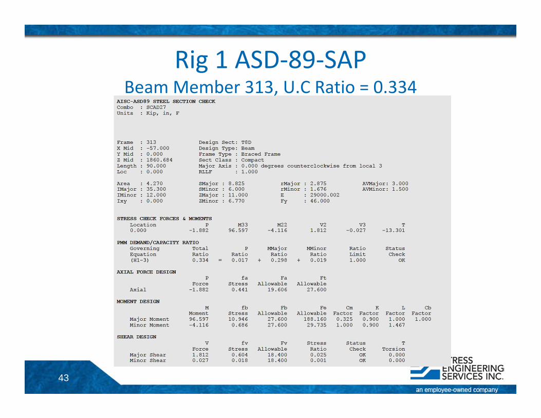
Rig 1 ASD‐89‐SAPBeam Member 313, U.C Ratio = 0.334
44
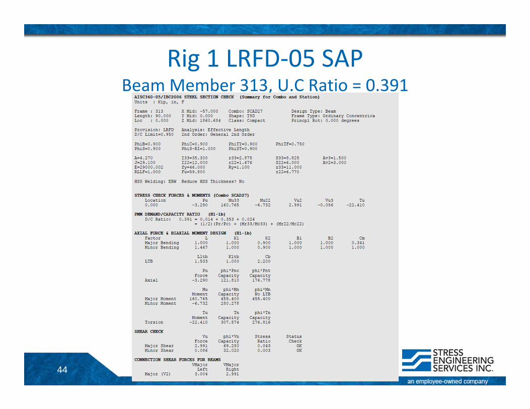
Rig 1 LRFD‐05 SAPBeam Member 313, U.C Ratio = 0.391
45
Rig 1Detailed Design Results for Selected Members• Beam• Brace• Column
46
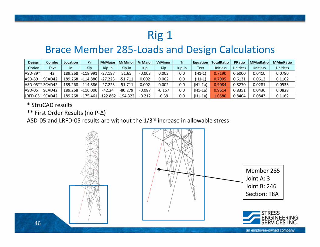
Rig 1Brace Member 285‐Loads and Design Calculations
Design Combo Location Pr MrMajor MrMinor VrMajor VrMinor Tr Equation TotalRatio PRatio MMajRatio MMinRatioOption Text in Kip Kip‐in Kip‐in Kip Kip Kip‐in Text Unitless Unitless Unitless Unitless
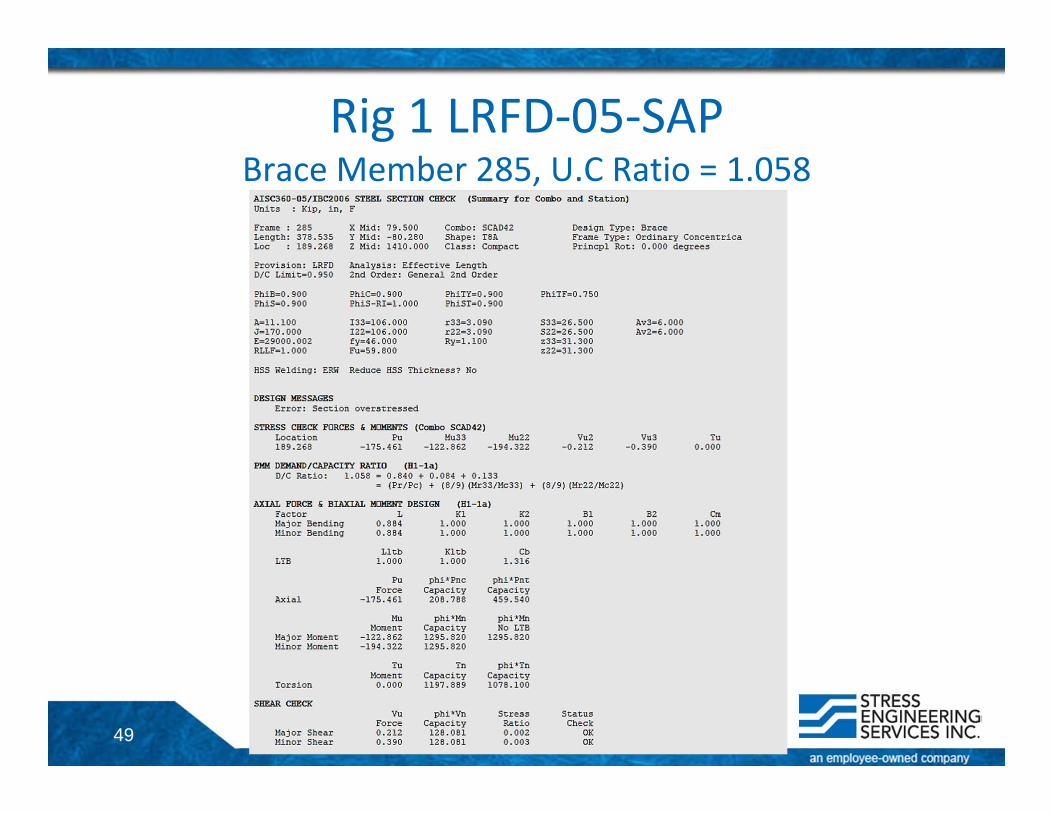
ASD‐89* 42 189.268 ‐118.991 ‐27.187 51.65 ‐0.003 0.003 0.0 (H1‐1) 0.7190 0.6000 0.0410 0.0780ASD‐89 SCAD42 189.268 ‐114.886 ‐27.223 ‐51.711 0.002 0.002 0.0 (H1‐1) 0.7905 0.6131 0.0612 0.1162ASD‐05** SCAD42 189.268 ‐114.886 ‐27.223 ‐51.711 0.002 0.002 0.0 (H1‐1a) 0.9084 0.8270 0.0281 0.0533ASD‐05 SCAD42 189.268 ‐116.006 ‐42.24 ‐80.279 ‐0.087 ‐0.157 0.0 (H1‐1a) 0.9614 0.8351 0.0436 0.0828LRFD‐05 SCAD42 189.268 ‐175.461 ‐122.862 ‐194.322 ‐0.212 ‐0.39 0.0 (H1‐1a) 1.0580 0.8404 0.0843 0.1162
* StruCAD results** First Order Results (no P‐Δ)ASD‐05 and LRFD‐05 results are without the 1/3rd increase in allowable stress
Member 285Joint A: 3Joint B: 246Section: T8A
47
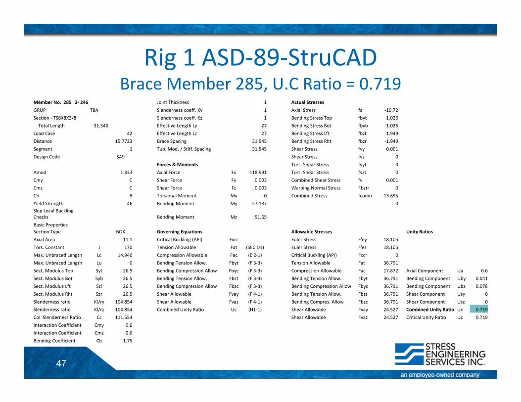
Rig 1 ASD‐89‐StruCADBrace Member 285, U.C Ratio = 0.719
Member No. 285 3‐ 246 Joint Thickness 1 Actual StressesGRUP T8A Slenderness coeff. Ky 1 Axial Stress fa ‐10.72Section ‐ TS8X8X3/8 Slenderness coeff. Kz 1 Bending Stress Top fbyt 1.026Total Length ‐31.545 Effective Length Ly 27 Bending Stress Bot fbyb ‐1.026
Load Case 42 Effective Length Lz 27 Bending Stress Lft fbzl 1.949Distance 15.7723 Brace Spacing 31.545 Bending Stress Rht fbzr ‐1.949Segment 1 Tub. Mod. / Stiff. Spacing 31.545 Shear Stress fvy 0.001Design Code SA9 Shear Stress fvz 0
Forces & Moments Tors. Shear Stress fvyt 0Amod 1.333 Axial Force Fx ‐118.991 Tors. Shear Stress fvzt 0Cmy C Shear Force Fy 0.003 Combined Shear Stress fv 0.001Cmz C Shear Force Fz ‐0.003 Warping Normal Stress Fbztr 0Cb B Torsional Moment Mx 0 Combined Stress fcomb ‐13.695Yield Strength 46 Bending Moment My ‐27.187 0Skip Local Buckling Checks Bending Moment Mz 51.65Basic PropertiesSection Type BOX Governing Equations Allowable Stresses Unity RatiosAxial Area 11.1 Critical Buckling (API) Fxcr Euler Stress F'ey 18.105Tors. Constant J 170 Tension Allowable Fat (SEC D1) Euler Stress F'ez 18.105Max. Unbraced Length Lc 14.946 Compression Allowable Fac (E 2‐1) Critical Buckling (API) Fxcr 0Max. Unbraced Length Lu 0 Bending Tension Allow. Fbyt (F 3‐3) Tension Allowable Fat 36.791Sect. Modulus Top Syt 26.5 Bending Compression Allow Fbyc (F 3‐3) Compression Allowable Fac 17.872 Axial Component Ua 0.6Sect. Modulus Bot Syb 26.5 Bending Tension Allow. Fbzt (F 3‐3) Bending Tension Allow. Fbyt 36.791 Bending Component Uby 0.041Sect. Modulus Lft Szl 26.5 Bending Compression Allow Fbzc (F 3‐3) Bending Compression Allow Fbyc 36.791 Bending Component Ubz 0.078Sect. Modulus Rht Szr 26.5 Shear Allowable Fvay (F 4‐1) Bending Tension Allow. Fbzt 36.791 Shear Component Usy 0Slenderness ratio Kl/ry 104.854 Shear Allowable Fvaz (F 4‐1) Bending Compres. Allow Fbzc 36.791 Shear Component Usz 0Slenderness ratio Kl/rz 104.854 Combined Unity Ratio Uc (H1‐1) Shear Allowable Fvay 24.527 Combined Unity Ratio Uc 0.719Col. Slenderness Ratio Cc 111.554 Shear Allowable Fvaz 24.527 Critical Unity Ratio Uc 0.719Interaction Coefficient Cmy 0.6Interaction Coefficient Cmz 0.6Bending Coefficient Cb 1.75
48
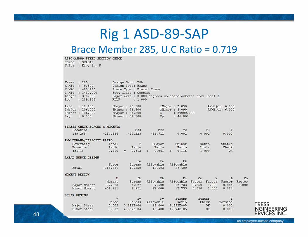
Rig 1 ASD‐89‐SAPBrace Member 285, U.C Ratio = 0.719
49
Rig 1 LRFD‐05‐SAPBrace Member 285, U.C Ratio = 1.058
50
Rig 1Detailed Design Results for Selected Members• Beam• Brace• Column
51
Rig 1Column Member 274‐Loads and Design Calculations
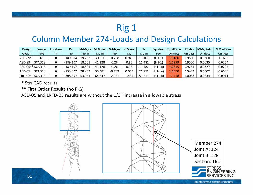
Design Combo Location Pr MrMajor MrMinor VrMajor VrMinor Tr Equation TotalRatio PRatio MMajRatio MMinRatioOption Text in Kip Kip‐in Kip‐in Kip Kip Kip‐in Text Unitless Unitless Unitless Unitless
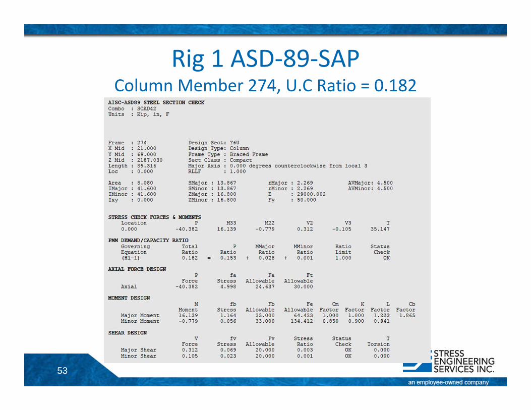
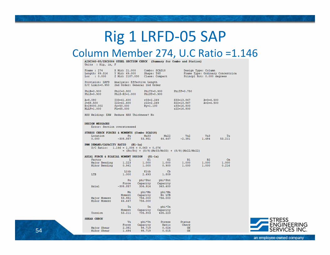
ASD‐89* 18 0 ‐189.804 19.262 ‐41.109 ‐0.268 0.945 13.102 (H1‐1) 1.0160 0.9530 0.0360 0.020ASD‐89 SCAD18 0 ‐189.107 18.501 41.128 0.26 0.95 11.482 (H1‐1) 1.0399 0.9500 0.0635 0.0264ASD‐05** SCAD18 0 ‐189.107 18.501 41.128 0.26 0.95 11.482 (H1‐1a) 1.0315 0.9261 0.0327 0.0727ASD‐05 SCAD18 0 ‐193.827 28.402 39.381 ‐0.703 0.953 26.752 (H1‐1a) 1.0690 0.9492 0.0502 0.0696LRFD‐05 SCAD18 0 ‐308.857 53.951 64.647 ‐2.381 1.484 53.211 (H1‐1a) 1.1458 1.0063 0.0634 0.0011
* StruCAD results** First Order Results (no P‐Δ)ASD‐05 and LRFD‐05 results are without the 1/3rd increase in allowable stress
Member 274Joint A: 124Joint B: 128Section: T6U
52
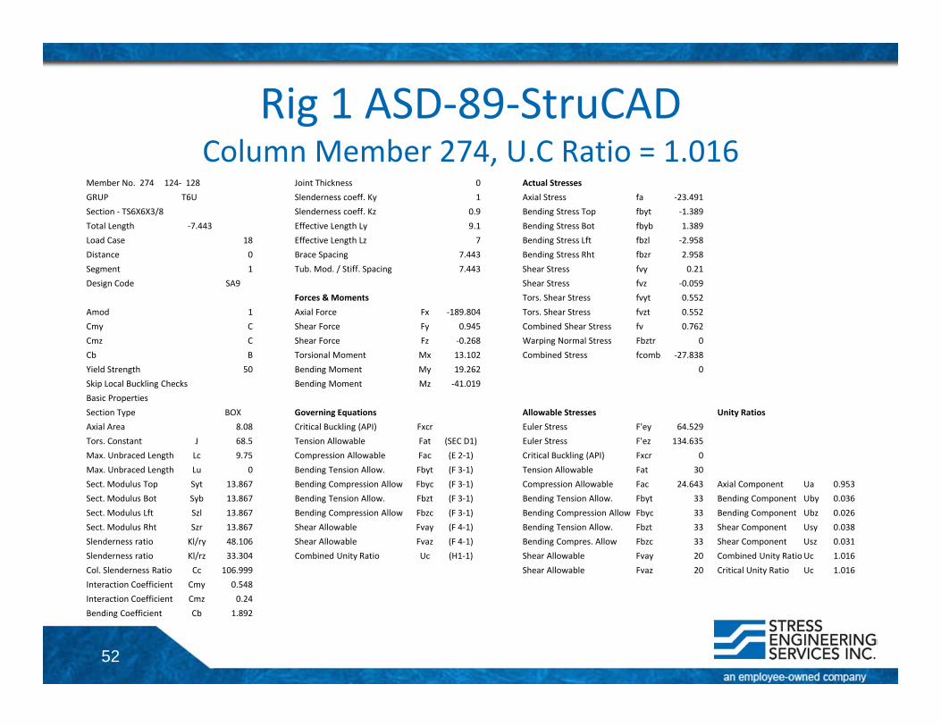
Rig 1 ASD‐89‐StruCADColumn Member 274, U.C Ratio = 1.016
Member No. 274 124‐ 128 Joint Thickness 0 Actual StressesGRUP T6U Slenderness coeff. Ky 1 Axial Stress fa ‐23.491Section ‐ TS6X6X3/8 Slenderness coeff. Kz 0.9 Bending Stress Top fbyt ‐1.389Total Length ‐7.443 Effective Length Ly 9.1 Bending Stress Bot fbyb 1.389Load Case 18 Effective Length Lz 7 Bending Stress Lft fbzl ‐2.958Distance 0 Brace Spacing 7.443 Bending Stress Rht fbzr 2.958Segment 1 Tub. Mod. / Stiff. Spacing 7.443 Shear Stress fvy 0.21Design Code SA9 Shear Stress fvz ‐0.059
Forces & Moments Tors. Shear Stress fvyt 0.552Amod 1 Axial Force Fx ‐189.804 Tors. Shear Stress fvzt 0.552Cmy C Shear Force Fy 0.945 Combined Shear Stress fv 0.762Cmz C Shear Force Fz ‐0.268 Warping Normal Stress Fbztr 0Cb B Torsional Moment Mx 13.102 Combined Stress fcomb ‐27.838Yield Strength 50 Bending Moment My 19.262 0Skip Local Buckling Checks Bending Moment Mz ‐41.019Basic PropertiesSection Type BOX Governing Equations Allowable Stresses Unity RatiosAxial Area 8.08 Critical Buckling (API) Fxcr Euler Stress F'ey 64.529Tors. Constant J 68.5 Tension Allowable Fat (SEC D1) Euler Stress F'ez 134.635Max. Unbraced Length Lc 9.75 Compression Allowable Fac (E 2‐1) Critical Buckling (API) Fxcr 0Max. Unbraced Length Lu 0 Bending Tension Allow. Fbyt (F 3‐1) Tension Allowable Fat 30Sect. Modulus Top Syt 13.867 Bending Compression Allow Fbyc (F 3‐1) Compression Allowable Fac 24.643 Axial Component Ua 0.953Sect. Modulus Bot Syb 13.867 Bending Tension Allow. Fbzt (F 3‐1) Bending Tension Allow. Fbyt 33 Bending Component Uby 0.036Sect. Modulus Lft Szl 13.867 Bending Compression Allow Fbzc (F 3‐1) Bending Compression Allow Fbyc 33 Bending Component Ubz 0.026Sect. Modulus Rht Szr 13.867 Shear Allowable Fvay (F 4‐1) Bending Tension Allow. Fbzt 33 Shear Component Usy 0.038Slenderness ratio Kl/ry 48.106 Shear Allowable Fvaz (F 4‐1) Bending Compres. Allow Fbzc 33 Shear Component Usz 0.031Slenderness ratio Kl/rz 33.304 Combined Unity Ratio Uc (H1‐1) Shear Allowable Fvay 20 Combined Unity RatioUc 1.016Col. Slenderness Ratio Cc 106.999 Shear Allowable Fvaz 20 Critical Unity Ratio Uc 1.016Interaction Coefficient Cmy 0.548Interaction Coefficient Cmz 0.24Bending Coefficient Cb 1.892
53
Rig 1 ASD‐89‐SAPColumn Member 274, U.C Ratio = 0.182
54
Rig 1 LRFD‐05 SAPColumn Member 274, U.C Ratio =1.146
55
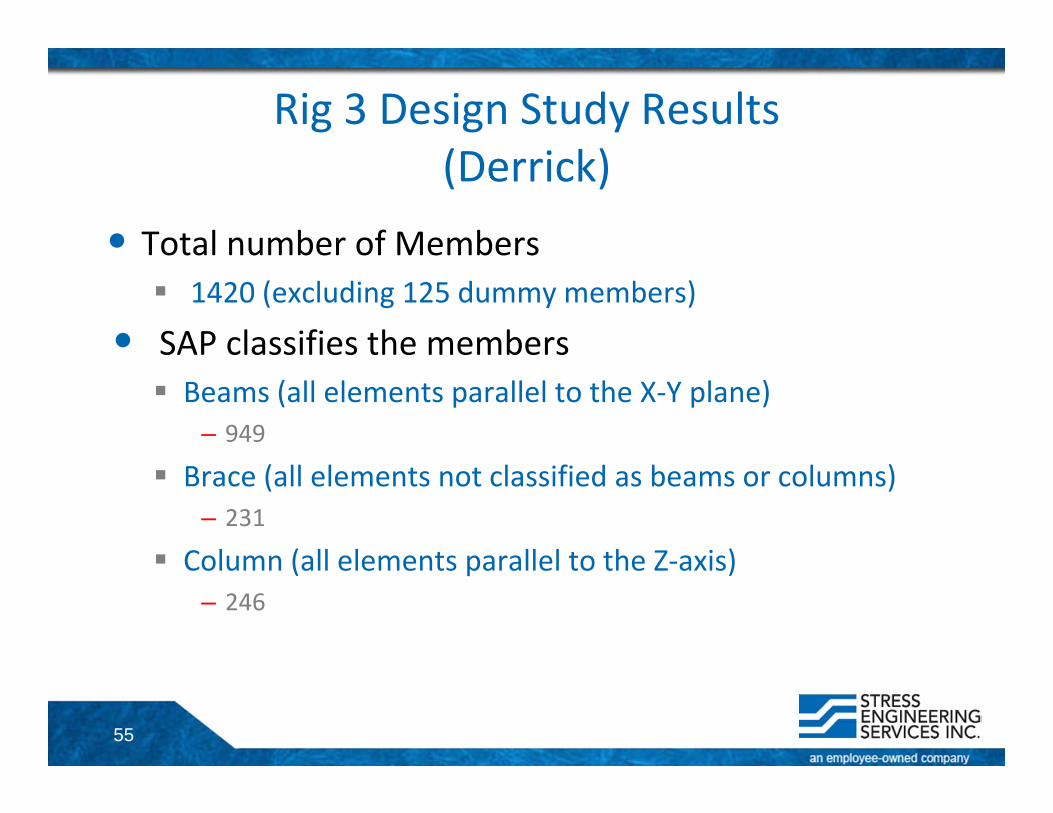
Rig 3 Design Study Results(Derrick)
• Total number of Members 1420 (excluding 125 dummy members)
• SAP classifies the members Beams (all elements parallel to the X‐Y plane)
– 949
Brace (all elements not classified as beams or columns)– 231
Column (all elements parallel to the Z‐axis)– 246
56
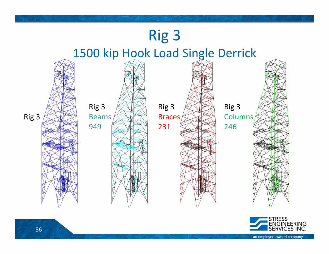
Rig 31500 kip Hook Load Single Derrick
Rig 3Rig 3Beams949
Rig 3Braces231
Rig 3Columns246
57
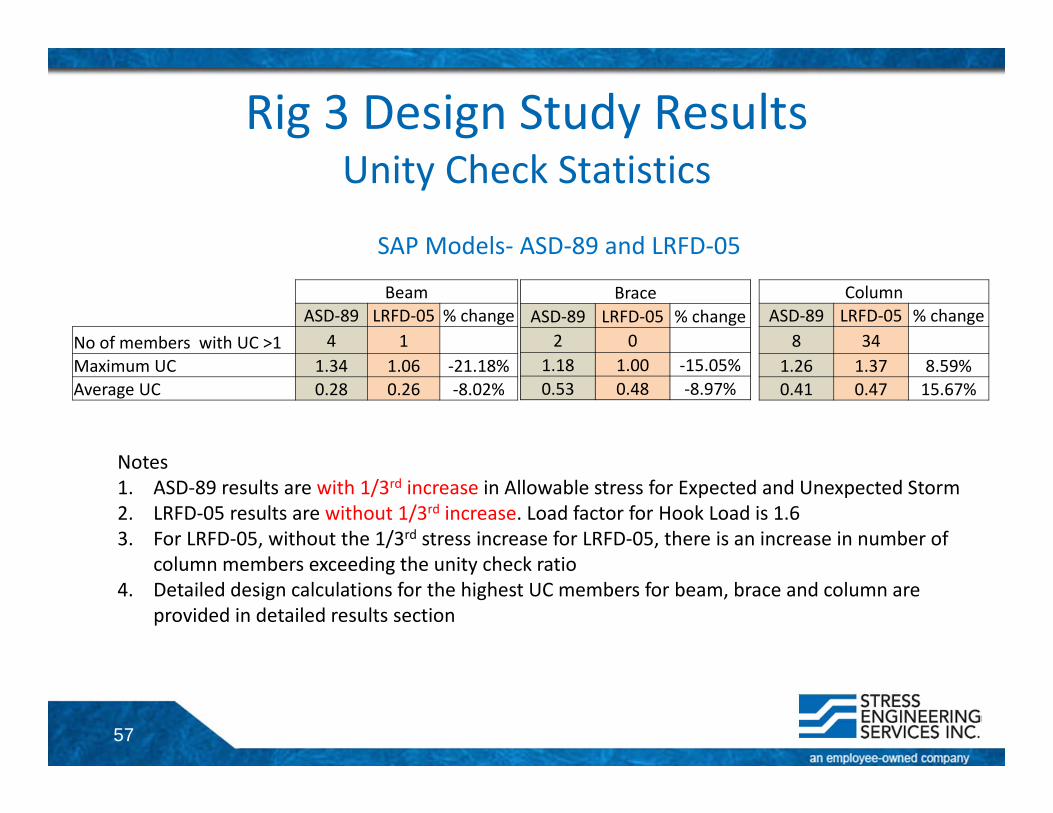
Rig 3 Design Study ResultsUnity Check Statistics
BeamASD‐89 LRFD‐05 % change
No of members with UC >1 4 1Maximum UC 1.34 1.06 ‐21.18%Average UC 0.28 0.26 ‐8.02%
BraceASD‐89 LRFD‐05 % change
2 01.18 1.00 ‐15.05%0.53 0.48 ‐8.97%
ColumnASD‐89 LRFD‐05 % change
8 341.26 1.37 8.59%0.41 0.47 15.67%
Notes1. ASD‐89 results are with 1/3rd increase in Allowable stress for Expected and Unexpected Storm2. LRFD‐05 results are without 1/3rd increase. Load factor for Hook Load is 1.63. For LRFD‐05, without the 1/3rd stress increase for LRFD‐05, there is an increase in number of
column members exceeding the unity check ratio4. Detailed design calculations for the highest UC members for beam, brace and column are
provided in detailed results section
SAP Models‐ ASD‐89 and LRFD‐05
58
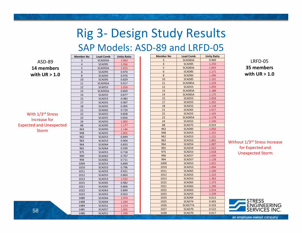
Rig 3‐ Design Study ResultsSAP Models: ASD‐89 and LRFD‐05
ASD‐8914 members with UR > 1.0
LRFD‐0535 members with UR > 1.0
With 1/3rd Stress Increase for
Expected and Unexpected Storm
Without 1/3rd Stress Increase for Expected and Unexpected Storm
Member No Load Comb Unity Ratio3 SCAD93A 1.0634 SCAD95 1.0565 SCAD93A 1.0156 SCAD95 0.9748 SCAD93 0.97610 SCAD95 0.82911 SCAD95A 0.91712 SCAD53 1.01613 SCAD93A 0.85914 SCAD55 0.87715 SCAD53 0.98317 SCAD55 0.90718 SCAD55 0.90521 SCAD65 0.72922 SCAD55 0.85823 SCAD55 0.85624 SCAD55 1.00268 SCAD95 1.177463 SCAD93 1.146948 SCAD55 1.001962 SCAD53 0.849963 SCAD53 0.904964 SCAD64 0.833965 SCAD64 0.939975 SCAD53 0.718990 SCAD62 0.767994 SCAD62 0.7111009 SCAD53 0.8991010 SCAD53 0.7961011 SCAD55 0.9211012 SCAD55 0.8031013 SCAD53 1.0321015 SCAD65 0.9821021 SCAD65 0.8061022 SCAD63 0.8991023 SCAD55 0.9531080 SCAD64 1.0741468 SCAD64 1.2641484 SCAD51 1.2141485 SCAD57 1.0051486 SCAD51 1.340
Member No Load Comb Unity Ratio3 SCAD83A 0.9694 SCAD85 1.2505 SCAD83A 1.0436 SCAD85 1.1718 SCAD83 1.20610 SCAD85 1.10111 SCAD85A 1.22912 SCAD53 1.05913 SCAD83A 1.18814 SCAD85A 1.17515 SCAD53 1.03417 SCAD55 1.26218 SCAD55 1.11821 SCAD65 1.01722 SCAD55 1.10323 SCAD85A 1.17824 SCAD55 1.23068 SCAD75 0.919463 SCAD83 1.056948 SCAD55 1.322962 SCAD53 1.121963 SCAD52 1.001964 SCAD54 1.087965 SCAD54 1.022975 SCAD53 1.018990 SCAD57 1.039994 SCAD57 1.1281009 SCAD53 1.0211010 SCAD53 1.0041011 SCAD65 1.2401012 SCAD55 1.2231013 SCAD53 1.3631015 SCAD65 1.3731021 SCAD65 1.1991022 SCAD63 1.0141023 SCAD55 1.2391024 SCAD94 0.0131025 SCAD74 0.4031026 SCAD77A 0.3331027 SCAD70 0.5221028 SCAD70 0.617
59
Rig 3Detailed Design Results for Selected
Members
60
Rig 3Detailed Design Results for Selected Members• Beam• Brace• Column
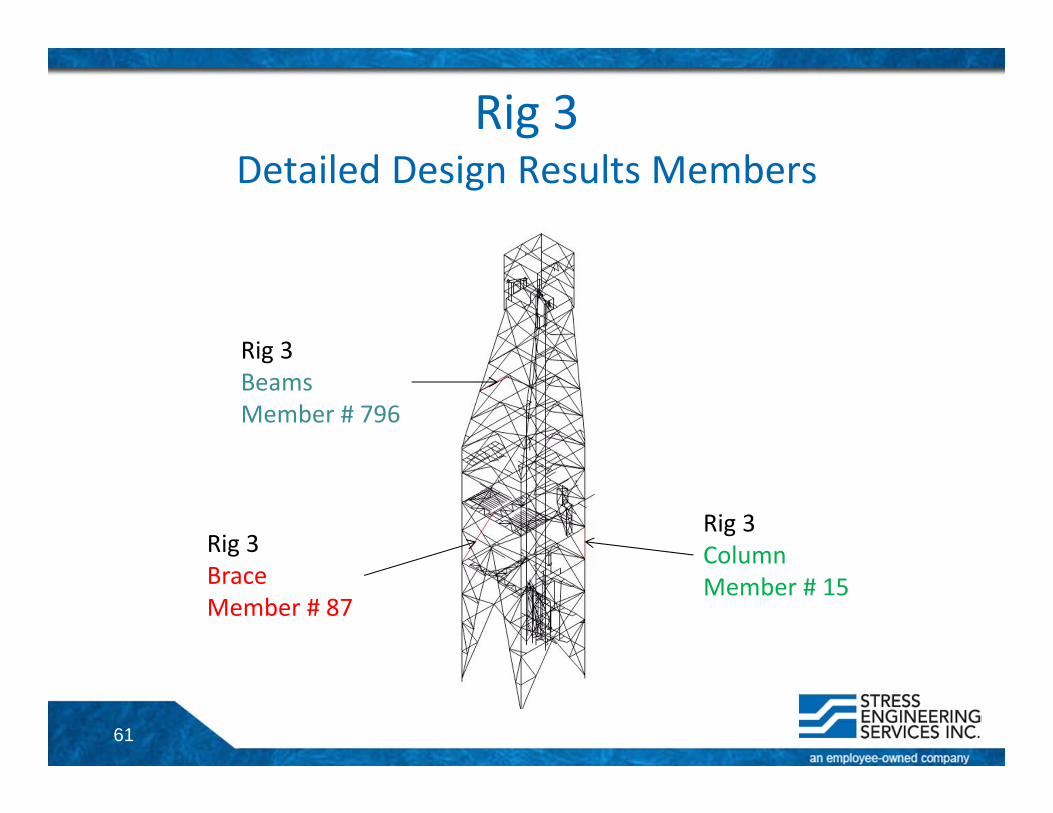
61
Rig 3 Detailed Design Results Members
Rig 3BeamsMember # 796
Rig 3BraceMember # 87
Rig 3Column Member # 15

62
Rig 3Detailed Design Results for Selected Members• Beam• Brace• Column
63
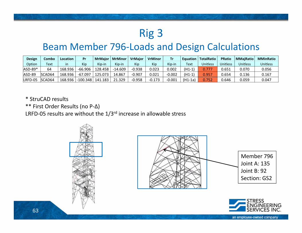
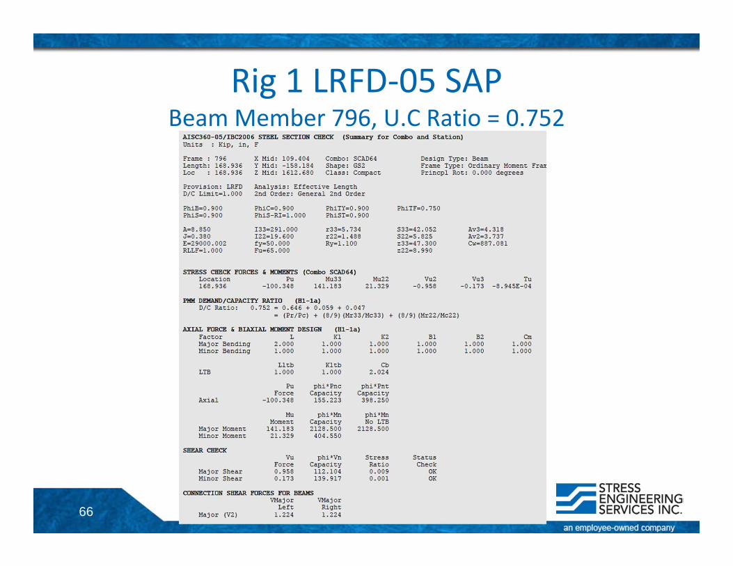
Rig 3Beam Member 796‐Loads and Design Calculations
Design Combo Location Pr MrMajor MrMinor VrMajor VrMinor Tr Equation TotalRatio PRatio MMajRatio MMinRatioOption Text in Kip Kip‐in Kip‐in Kip Kip Kip‐in Text Unitless Unitless Unitless Unitless
ASD‐89* 64 168.936 ‐66.906 128.458 ‐14.609 ‐0.938 0.023 0.002 (H1‐1) 0.777 0.651 0.070 0.056ASD‐89 SCAD64 168.936 ‐67.097 125.073 14.867 ‐0.907 0.021 ‐0.002 (H1‐1) 0.957 0.654 0.136 0.167LRFD‐05 SCAD64 168.936 ‐100.348 141.183 21.329 ‐0.958 ‐0.173 ‐0.001 (H1‐1a) 0.752 0.646 0.059 0.047
* StruCAD results** First Order Results (no P‐Δ)LRFD‐05 results are without the 1/3rd increase in allowable stress
Member 796Joint A: 135Joint B: 92Section: GS2
64
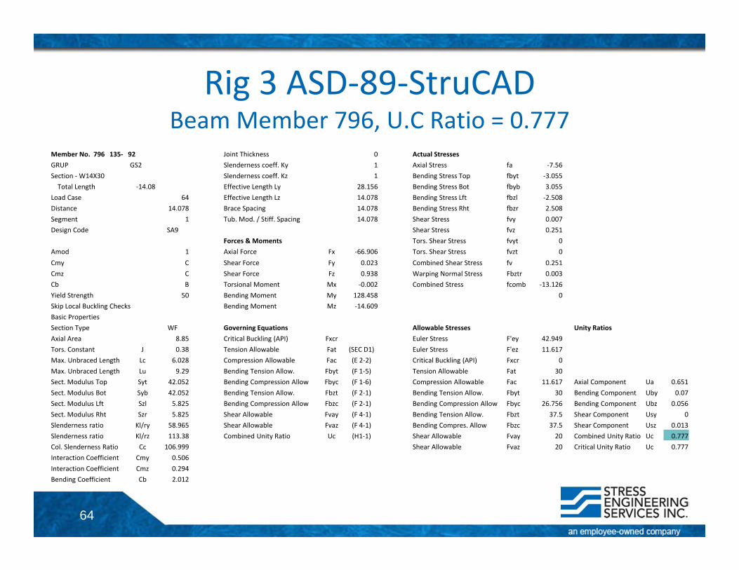
Rig 3 ASD‐89‐StruCADBeam Member 796, U.C Ratio = 0.777
Member No. 796 135‐ 92 Joint Thickness 0 Actual StressesGRUP GS2 Slenderness coeff. Ky 1 Axial Stress fa ‐7.56Section ‐W14X30 Slenderness coeff. Kz 1 Bending Stress Top fbyt ‐3.055Total Length ‐14.08 Effective Length Ly 28.156 Bending Stress Bot fbyb 3.055
Load Case 64 Effective Length Lz 14.078 Bending Stress Lft fbzl ‐2.508Distance 14.078 Brace Spacing 14.078 Bending Stress Rht fbzr 2.508Segment 1 Tub. Mod. / Stiff. Spacing 14.078 Shear Stress fvy 0.007Design Code SA9 Shear Stress fvz 0.251
Forces & Moments Tors. Shear Stress fvyt 0Amod 1 Axial Force Fx ‐66.906 Tors. Shear Stress fvzt 0Cmy C Shear Force Fy 0.023 Combined Shear Stress fv 0.251Cmz C Shear Force Fz 0.938 Warping Normal Stress Fbztr 0.003Cb B Torsional Moment Mx ‐0.002 Combined Stress fcomb ‐13.126Yield Strength 50 Bending Moment My 128.458 0Skip Local Buckling Checks Bending Moment Mz ‐14.609Basic PropertiesSection Type WF Governing Equations Allowable Stresses Unity RatiosAxial Area 8.85 Critical Buckling (API) Fxcr Euler Stress F'ey 42.949Tors. Constant J 0.38 Tension Allowable Fat (SEC D1) Euler Stress F'ez 11.617Max. Unbraced Length Lc 6.028 Compression Allowable Fac (E 2‐2) Critical Buckling (API) Fxcr 0Max. Unbraced Length Lu 9.29 Bending Tension Allow. Fbyt (F 1‐5) Tension Allowable Fat 30Sect. Modulus Top Syt 42.052 Bending Compression Allow Fbyc (F 1‐6) Compression Allowable Fac 11.617 Axial Component Ua 0.651Sect. Modulus Bot Syb 42.052 Bending Tension Allow. Fbzt (F 2‐1) Bending Tension Allow. Fbyt 30 Bending Component Uby 0.07Sect. Modulus Lft Szl 5.825 Bending Compression Allow Fbzc (F 2‐1) Bending Compression Allow Fbyc 26.756 Bending Component Ubz 0.056Sect. Modulus Rht Szr 5.825 Shear Allowable Fvay (F 4‐1) Bending Tension Allow. Fbzt 37.5 Shear Component Usy 0Slenderness ratio Kl/ry 58.965 Shear Allowable Fvaz (F 4‐1) Bending Compres. Allow Fbzc 37.5 Shear Component Usz 0.013Slenderness ratio Kl/rz 113.38 Combined Unity Ratio Uc (H1‐1) Shear Allowable Fvay 20 Combined Unity Ratio Uc 0.777Col. Slenderness Ratio Cc 106.999 Shear Allowable Fvaz 20 Critical Unity Ratio Uc 0.777Interaction Coefficient Cmy 0.506Interaction Coefficient Cmz 0.294Bending Coefficient Cb 2.012
65
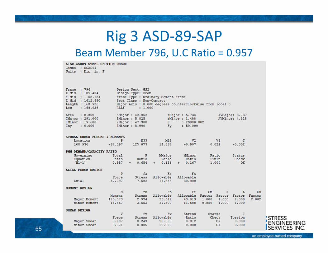
Rig 3 ASD‐89‐SAPBeam Member 796, U.C Ratio = 0.957
66
Rig 1 LRFD‐05 SAPBeam Member 796, U.C Ratio = 0.752

67
Rig 3Detailed Design Results for Selected Members• Beam• Brace• Column
68
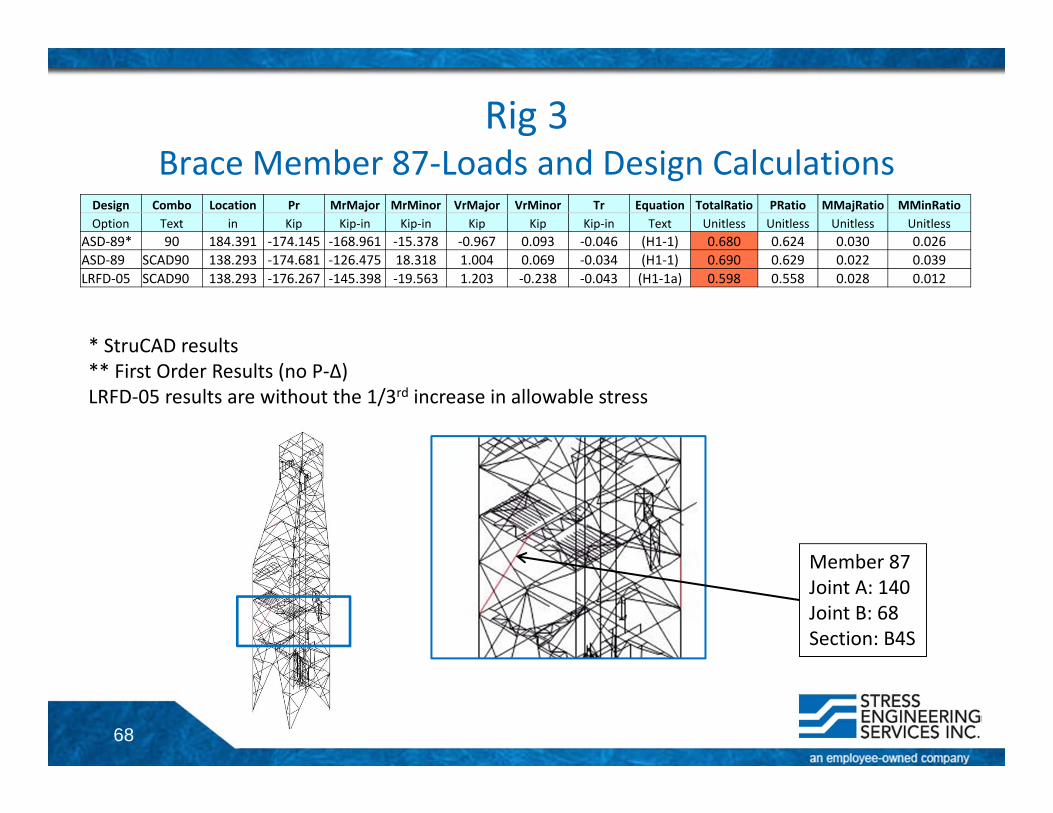
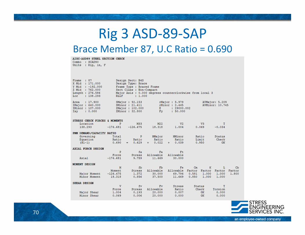
Rig 3Brace Member 87‐Loads and Design Calculations
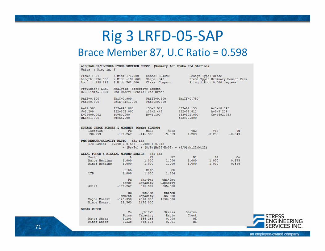
Design Combo Location Pr MrMajor MrMinor VrMajor VrMinor Tr Equation TotalRatio PRatio MMajRatio MMinRatioOption Text in Kip Kip‐in Kip‐in Kip Kip Kip‐in Text Unitless Unitless Unitless Unitless
ASD‐89* 90 184.391 ‐174.145 ‐168.961 ‐15.378 ‐0.967 0.093 ‐0.046 (H1‐1) 0.680 0.624 0.030 0.026ASD‐89 SCAD90 138.293 ‐174.681 ‐126.475 18.318 1.004 0.069 ‐0.034 (H1‐1) 0.690 0.629 0.022 0.039LRFD‐05 SCAD90 138.293 ‐176.267 ‐145.398 ‐19.563 1.203 ‐0.238 ‐0.043 (H1‐1a) 0.598 0.558 0.028 0.012
* StruCAD results** First Order Results (no P‐Δ)LRFD‐05 results are without the 1/3rd increase in allowable stress
Member 87Joint A: 140Joint B: 68Section: B4S
69
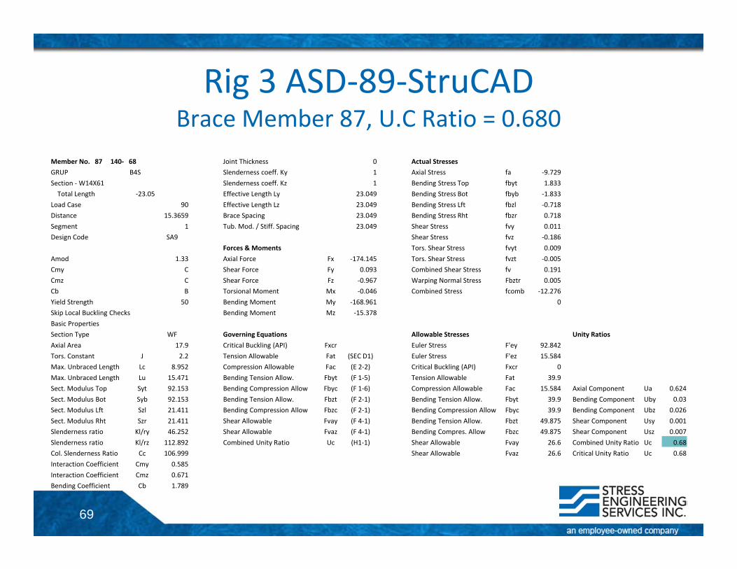
Rig 3 ASD‐89‐StruCADBrace Member 87, U.C Ratio = 0.680
Member No. 87 140‐ 68 Joint Thickness 0 Actual StressesGRUP B4S Slenderness coeff. Ky 1 Axial Stress fa ‐9.729Section ‐W14X61 Slenderness coeff. Kz 1 Bending Stress Top fbyt 1.833Total Length ‐23.05 Effective Length Ly 23.049 Bending Stress Bot fbyb ‐1.833
Load Case 90 Effective Length Lz 23.049 Bending Stress Lft fbzl ‐0.718Distance 15.3659 Brace Spacing 23.049 Bending Stress Rht fbzr 0.718Segment 1 Tub. Mod. / Stiff. Spacing 23.049 Shear Stress fvy 0.011Design Code SA9 Shear Stress fvz ‐0.186
Forces & Moments Tors. Shear Stress fvyt 0.009Amod 1.33 Axial Force Fx ‐174.145 Tors. Shear Stress fvzt ‐0.005Cmy C Shear Force Fy 0.093 Combined Shear Stress fv 0.191Cmz C Shear Force Fz ‐0.967 Warping Normal Stress Fbztr 0.005Cb B Torsional Moment Mx ‐0.046 Combined Stress fcomb ‐12.276Yield Strength 50 Bending Moment My ‐168.961 0Skip Local Buckling Checks Bending Moment Mz ‐15.378Basic PropertiesSection Type WF Governing Equations Allowable Stresses Unity RatiosAxial Area 17.9 Critical Buckling (API) Fxcr Euler Stress F'ey 92.842Tors. Constant J 2.2 Tension Allowable Fat (SEC D1) Euler Stress F'ez 15.584Max. Unbraced Length Lc 8.952 Compression Allowable Fac (E 2‐2) Critical Buckling (API) Fxcr 0Max. Unbraced Length Lu 15.471 Bending Tension Allow. Fbyt (F 1‐5) Tension Allowable Fat 39.9Sect. Modulus Top Syt 92.153 Bending Compression Allow Fbyc (F 1‐6) Compression Allowable Fac 15.584 Axial Component Ua 0.624Sect. Modulus Bot Syb 92.153 Bending Tension Allow. Fbzt (F 2‐1) Bending Tension Allow. Fbyt 39.9 Bending Component Uby 0.03Sect. Modulus Lft Szl 21.411 Bending Compression Allow Fbzc (F 2‐1) Bending Compression Allow Fbyc 39.9 Bending Component Ubz 0.026Sect. Modulus Rht Szr 21.411 Shear Allowable Fvay (F 4‐1) Bending Tension Allow. Fbzt 49.875 Shear Component Usy 0.001Slenderness ratio Kl/ry 46.252 Shear Allowable Fvaz (F 4‐1) Bending Compres. Allow Fbzc 49.875 Shear Component Usz 0.007Slenderness ratio Kl/rz 112.892 Combined Unity Ratio Uc (H1‐1) Shear Allowable Fvay 26.6 Combined Unity Ratio Uc 0.68Col. Slenderness Ratio Cc 106.999 Shear Allowable Fvaz 26.6 Critical Unity Ratio Uc 0.68Interaction Coefficient Cmy 0.585Interaction Coefficient Cmz 0.671Bending Coefficient Cb 1.789
70
Rig 3 ASD‐89‐SAPBrace Member 87, U.C Ratio = 0.690
71
Rig 3 LRFD‐05‐SAPBrace Member 87, U.C Ratio = 0.598
72
Rig 3Detailed Design Results for Selected Members• Beam• Brace• Column
73
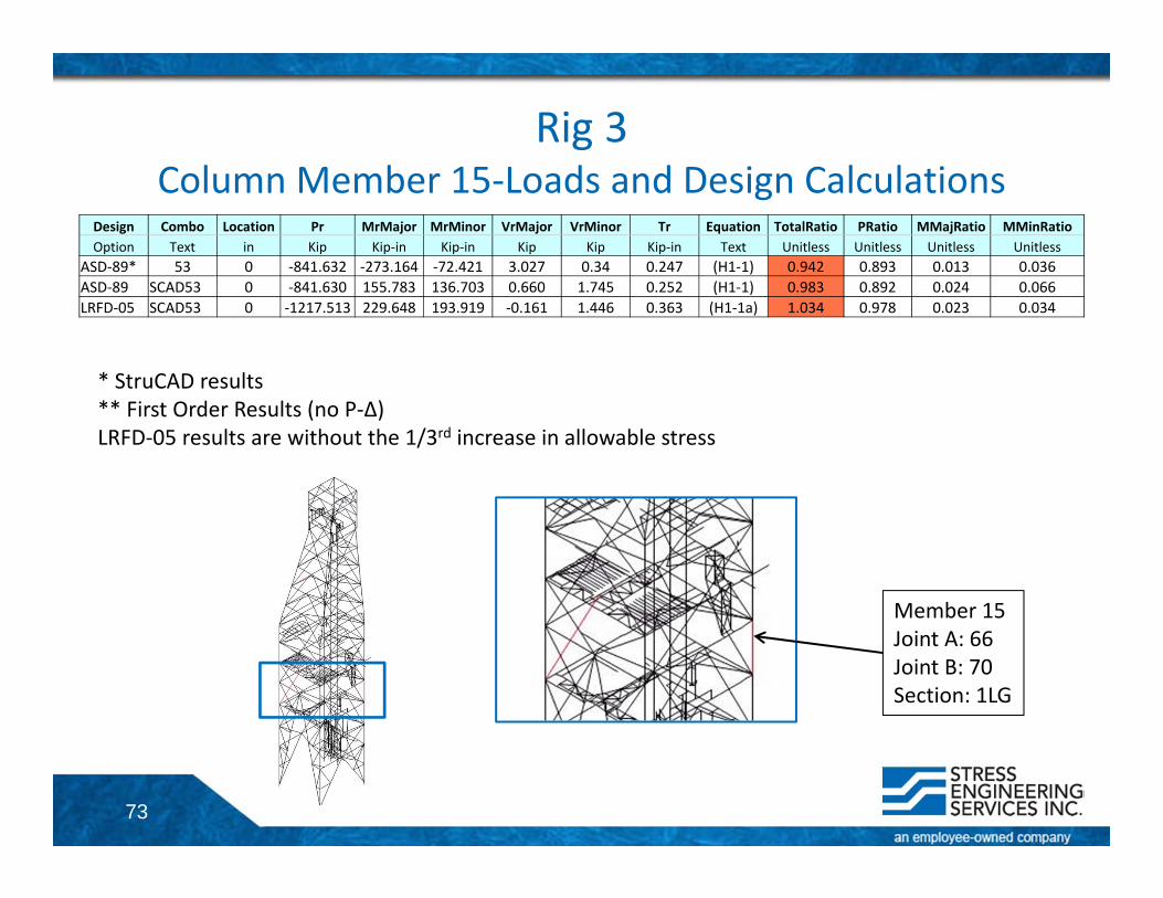
Rig 3Column Member 15‐Loads and Design Calculations
Design Combo Location Pr MrMajor MrMinor VrMajor VrMinor Tr Equation TotalRatio PRatio MMajRatio MMinRatioOption Text in Kip Kip‐in Kip‐in Kip Kip Kip‐in Text Unitless Unitless Unitless Unitless
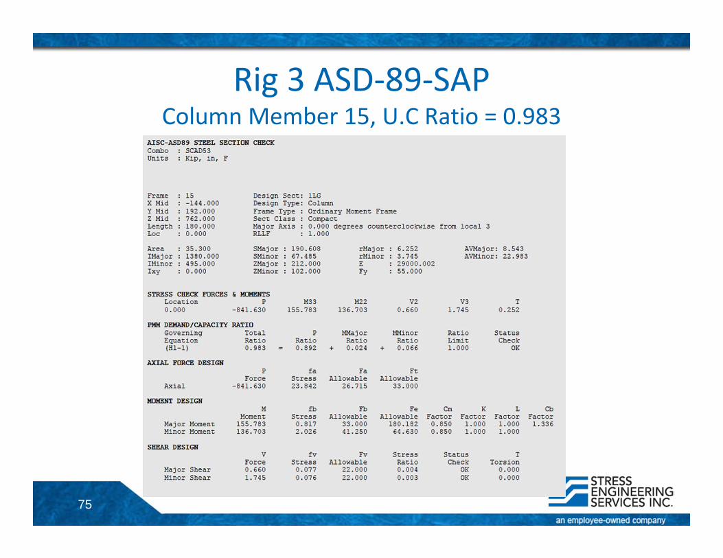
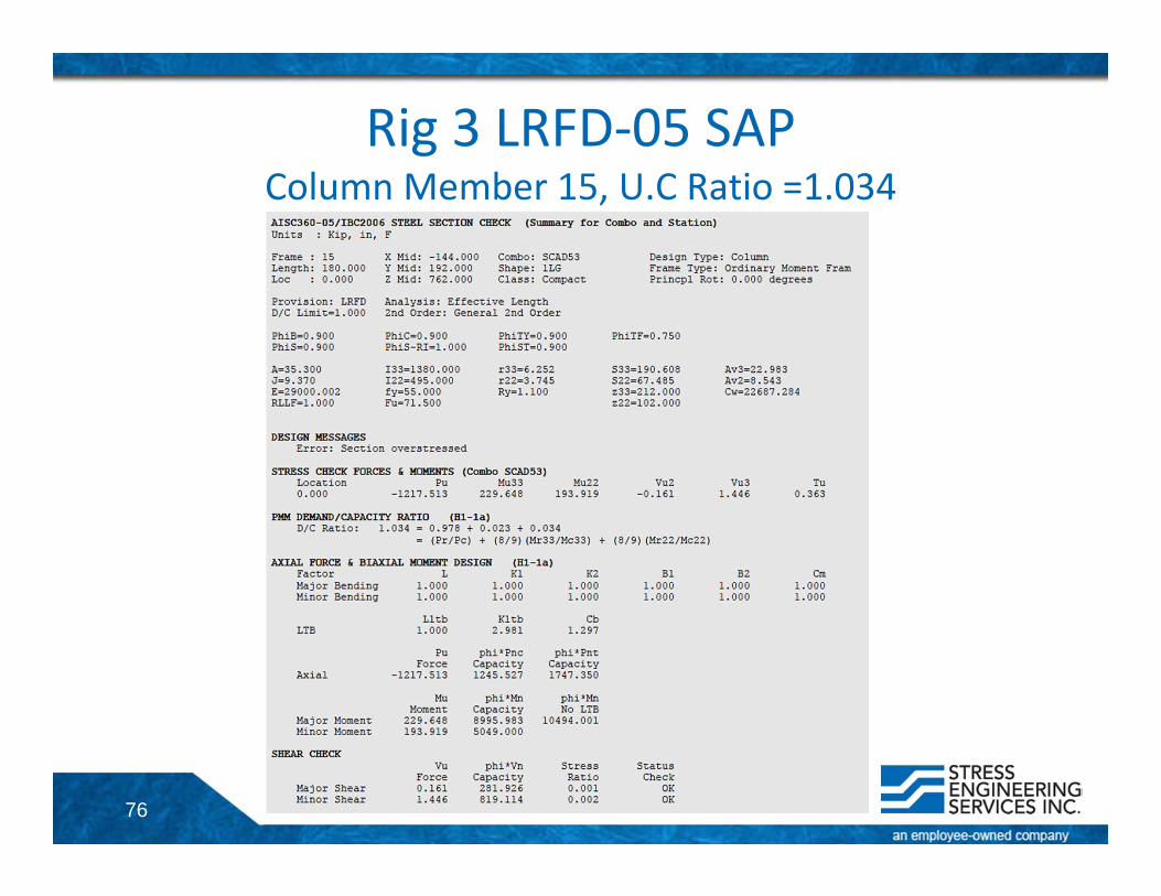
ASD‐89* 53 0 ‐841.632 ‐273.164 ‐72.421 3.027 0.34 0.247 (H1‐1) 0.942 0.893 0.013 0.036ASD‐89 SCAD53 0 ‐841.630 155.783 136.703 0.660 1.745 0.252 (H1‐1) 0.983 0.892 0.024 0.066LRFD‐05 SCAD53 0 ‐1217.513 229.648 193.919 ‐0.161 1.446 0.363 (H1‐1a) 1.034 0.978 0.023 0.034
* StruCAD results** First Order Results (no P‐Δ)LRFD‐05 results are without the 1/3rd increase in allowable stress
Member 15Joint A: 66Joint B: 70Section: 1LG
74
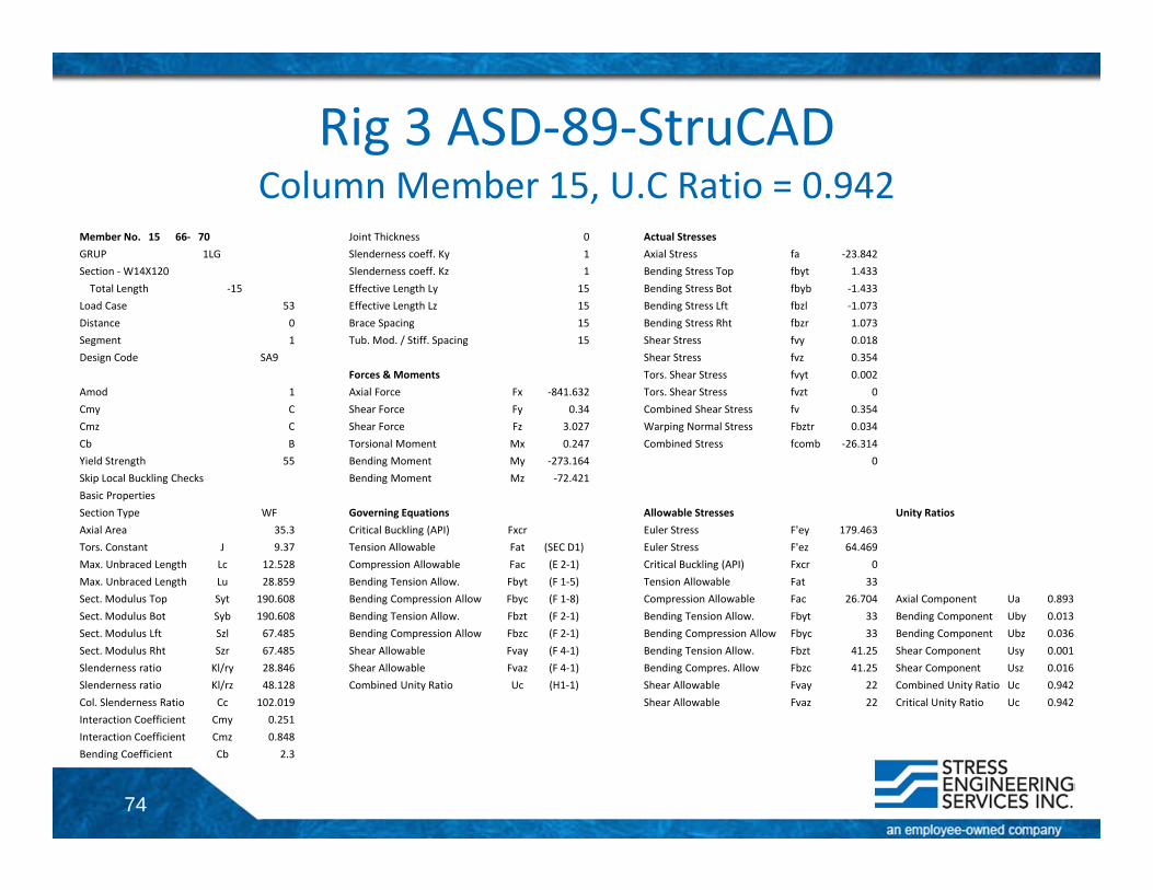
Rig 3 ASD‐89‐StruCADColumn Member 15, U.C Ratio = 0.942
Member No. 15 66‐ 70 Joint Thickness 0 Actual StressesGRUP 1LG Slenderness coeff. Ky 1 Axial Stress fa ‐23.842Section ‐W14X120 Slenderness coeff. Kz 1 Bending Stress Top fbyt 1.433Total Length ‐15 Effective Length Ly 15 Bending Stress Bot fbyb ‐1.433
Load Case 53 Effective Length Lz 15 Bending Stress Lft fbzl ‐1.073Distance 0 Brace Spacing 15 Bending Stress Rht fbzr 1.073Segment 1 Tub. Mod. / Stiff. Spacing 15 Shear Stress fvy 0.018Design Code SA9 Shear Stress fvz 0.354
Forces & Moments Tors. Shear Stress fvyt 0.002Amod 1 Axial Force Fx ‐841.632 Tors. Shear Stress fvzt 0Cmy C Shear Force Fy 0.34 Combined Shear Stress fv 0.354Cmz C Shear Force Fz 3.027 Warping Normal Stress Fbztr 0.034Cb B Torsional Moment Mx 0.247 Combined Stress fcomb ‐26.314Yield Strength 55 Bending Moment My ‐273.164 0Skip Local Buckling Checks Bending Moment Mz ‐72.421Basic PropertiesSection Type WF Governing Equations Allowable Stresses Unity RatiosAxial Area 35.3 Critical Buckling (API) Fxcr Euler Stress F'ey 179.463Tors. Constant J 9.37 Tension Allowable Fat (SEC D1) Euler Stress F'ez 64.469Max. Unbraced Length Lc 12.528 Compression Allowable Fac (E 2‐1) Critical Buckling (API) Fxcr 0Max. Unbraced Length Lu 28.859 Bending Tension Allow. Fbyt (F 1‐5) Tension Allowable Fat 33Sect. Modulus Top Syt 190.608 Bending Compression Allow Fbyc (F 1‐8) Compression Allowable Fac 26.704 Axial Component Ua 0.893Sect. Modulus Bot Syb 190.608 Bending Tension Allow. Fbzt (F 2‐1) Bending Tension Allow. Fbyt 33 Bending Component Uby 0.013Sect. Modulus Lft Szl 67.485 Bending Compression Allow Fbzc (F 2‐1) Bending Compression Allow Fbyc 33 Bending Component Ubz 0.036Sect. Modulus Rht Szr 67.485 Shear Allowable Fvay (F 4‐1) Bending Tension Allow. Fbzt 41.25 Shear Component Usy 0.001Slenderness ratio Kl/ry 28.846 Shear Allowable Fvaz (F 4‐1) Bending Compres. Allow Fbzc 41.25 Shear Component Usz 0.016Slenderness ratio Kl/rz 48.128 Combined Unity Ratio Uc (H1‐1) Shear Allowable Fvay 22 Combined Unity Ratio Uc 0.942Col. Slenderness Ratio Cc 102.019 Shear Allowable Fvaz 22 Critical Unity Ratio Uc 0.942Interaction Coefficient Cmy 0.251Interaction Coefficient Cmz 0.848Bending Coefficient Cb 2.3
75
Rig 3 ASD‐89‐SAPColumn Member 15, U.C Ratio = 0.983
76
Rig 3 LRFD‐05 SAPColumn Member 15, U.C Ratio =1.034
77
Contact InformationMike Effenberger, [email protected]
Sathish Ramamoorthy, [email protected]
Stress Engineering Services13800 Westfair East DriveHouston, Texas 77041
Phone: (281) 955‐2900Fax: (281) 955‐2638www.stress.com