Doctorate Thesis Hannu Peltonen
188
Concepts and an Implementation for Product Data Management Doctorate Thesis Hannu Peltonen Helsinki University of Technology Department of Computer Science and Engineering P.O. Box 9555 FIN-02015 HUT, Finland [email protected]
Transcript of Doctorate Thesis Hannu Peltonen

Concepts and an Implementation for Product Data Management
Doctorate Thesis
Hannu Peltonen
Helsinki University of TechnologyDepartment of Computer Science and Engineering
P.O. Box 9555FIN-02015 HUT, [email protected]

2
Peltonen, H., Concepts and an Implementation for Product Data Manage-ment. Acta Polytechnica Scandinavica, Mathematics and Computing Series No. 105,Espoo 2000, 188 pp. Published by the The Finnish Academies of Technology. ISBN951-666-538-1. ISSN 1456-9418.
Keywords: Product data management, document management, configurable prod-ucts
AbstractShorter product life-cycles, growing product complexity and the need for a largenumber of product variants have made Product Data Management (PDM) increas-ingly important for many manufacturing companies. This thesis provides a survey ofthe most important concepts of PDM technology and illustrates the concepts bydescribing the design and implementation of an advanced document managementsystem.
The survey in the first part of the thesis illustrates the relations between differentconcepts and can be used as a framework for evaluating PDM systems. This partincludes summaries of the STEP standards for product models and the IEC 6130 andISO 13584 standards for component management. The STEP standards are partic-ularly difficult to read, and these sections of the thesis provide accessible introduc-tions to these very complex standards.
The document management system described in the second part of the thesis hasbeen developed in close co-operation with a large manufacturing company, whichnow stores all engineering documents in the system and accesses the system througha global intranet. The main strengths of the system are its versatile document modeland the flexible customisation properties of the system, including dynamic schemamanipulation operations and a programmable authorisation mechanism.
One particular topic in the thesis is product configuration. The first part intro-duces a framework for configurable products in terms of an explicit structure andconstraints. The second part discusses different ways to add product family struc-tures to the implemented system.
© All rights reserved. No part of the publication may be reproduced, stored, or trans-mitted, in any form or by any means, electronic, mechanical, photocopying, record-ing, or otherwise without the prior written permission of the author.

3
PrefaceThe work reported in this thesis was completed between 1991 and 1999 within theProduct Data Management Group (PDMG) at the TAI Research Centre at the Hel-sinki University of Technology. The work was done in multiple projects, which weremainly financed by the National Technology Agency of Finland (Tekes) and KONEElevators. Some projects were part of the Rapid programme co-ordinated by theFederation of Finnish Metal, Engineering and Electrotechnical Industries (MET).
My first thanks go to professor Reijo Sulonen, who has supervised the preparationof this thesis and has guided the research group. I also thank Kim Gunell, Asko Mar-tio, Tomi Männistö, Kati Sarinko, Timo Soininen and Juha Tiihonen for giving methe opportunity to work in a stimulating and pleasant research environment. It hasbeen wunderful to know you and all the other people at our office in Spektri Duo. Ihope we shall work together, and occasionally also meet outside the office, for manymore years.
I would also like to thank Dr. Peter van den Hamer for important comments thatimproved the thesis crucially in its last stages.
I have designed and implemented most of the server of the EDMS documentmanagement system. The original model for generic product structures in EDMSwas developed by Asko Martio. Timo Nyyssönen has implemented the object filtersin the server. Kari Alho implemented the X/Motif user interface of the EDMS. Theoriginal object manager was implemented by Kari Alho, Tomi Männistö and myself.The Java user interface was originally implemented as a student project by JanneKontkanen, Sami Vaarala, Phuoc Tran Minh, Janne Huttunen, Pekka Salmia, KimGunell and Teppo Peltonen. Kim Gunell has joined our research group and contin-ues the development of the interface. Fredrik Nyberg at KONE Elevators has alsowritten some parts of the user interface. The object manager of the Java user interfaceis now being developed by Kim Gunell and myself.
The success of EDMS has depended on the support of people at KONE Eleva-tors. Asko Martio was in charge of the EDMS project at KONE before joining ourresearch group. Without his faith in the project there would be no system to write athesis about. Asko’s work at KONE has been continued by Matti Eskola, who hasbeen the best possible promoter for the system both within and outside the company.Heikki Karhunen and Jorma Heimonen have been responsible for actually makingthe system run at KONE. Jorma Heimonen has also written the Web tools, whichhave been crucial for the success of the whole project.
I have written the Application Programming Interface of EDMS, which has beenused by Jarmo Ukkola and Kalevi Turkia at Vertex Systems Oy to implement a linkbetween EDMS and the Vertex CAD program. At KONE Elevators, the Vertex linkhas been managed by Jussi Nissi.

4
The English language of the thesis has been checked by Ms Kathleen Tipton.Finally, I would like to thank my wife Marja for the most important things in life:
love and companionship.
Helsinki, May 2000
Hannu Peltonen
5
Contents
Abstract . . . . . . . . . . . . . . . . . . . . . . . . . . . . . . . . . . . . . . . . . . . . . . 2Preface . . . . . . . . . . . . . . . . . . . . . . . . . . . . . . . . . . . . . . . . . . . . . . . 3Contents. . . . . . . . . . . . . . . . . . . . . . . . . . . . . . . . . . . . . . . . . . . . . . 5
List of Figures . . . . . . . . . . . . . . . . . . . . . . . . . . . . . . . . . . . . . . . . 11
1 Introduction . . . . . . . . . . . . . . . . . . . . . . . . . . . . . . . . . . . . . 131.1 History of the Thesis . . . . . . . . . . . . . . . . . . . . . . . . . . . . . . . . . . . . . . 131.2 Contributions of the Thesis . . . . . . . . . . . . . . . . . . . . . . . . . . . . . . . . . 141.3 Methods . . . . . . . . . . . . . . . . . . . . . . . . . . . . . . . . . . . . . . . . . . . . . . . . . 151.4 Structure of the Thesis . . . . . . . . . . . . . . . . . . . . . . . . . . . . . . . . . . . . . 15
Part I: Product Data Management Concepts
2 Product Data and Product Data Management . . . . . . . . . . 182.1 Product Data . . . . . . . . . . . . . . . . . . . . . . . . . . . . . . . . . . . . . . . . . . . . . 182.2 Product Data Management. . . . . . . . . . . . . . . . . . . . . . . . . . . . . . . . . . 182.3 Basic Functions of a PDM System. . . . . . . . . . . . . . . . . . . . . . . . . . . . 192.4 PDM Projects . . . . . . . . . . . . . . . . . . . . . . . . . . . . . . . . . . . . . . . . . . . . 21
3 Data Models . . . . . . . . . . . . . . . . . . . . . . . . . . . . . . . . . . . . . 223.1 Metamodels and Company Models . . . . . . . . . . . . . . . . . . . . . . . . . . . 223.2 Basic Data Modelling Concepts . . . . . . . . . . . . . . . . . . . . . . . . . . . . . . 24
3.2.1 Objects and Types . . . . . . . . . . . . . . . . . . . . . . . . . . . . . . . . . 243.2.2 Attributes . . . . . . . . . . . . . . . . . . . . . . . . . . . . . . . . . . . . . . . . 283.2.3 Relations . . . . . . . . . . . . . . . . . . . . . . . . . . . . . . . . . . . . . . . . . 33
3.3 Products. . . . . . . . . . . . . . . . . . . . . . . . . . . . . . . . . . . . . . . . . . . . . . . . . 343.3.1 Product Structures . . . . . . . . . . . . . . . . . . . . . . . . . . . . . . . . . 353.3.2 Configurable Products . . . . . . . . . . . . . . . . . . . . . . . . . . . . . . 37
3.4 Documents . . . . . . . . . . . . . . . . . . . . . . . . . . . . . . . . . . . . . . . . . . . . . . 473.5 Versioning . . . . . . . . . . . . . . . . . . . . . . . . . . . . . . . . . . . . . . . . . . . . . . . 50
3.5.1 Revisions. . . . . . . . . . . . . . . . . . . . . . . . . . . . . . . . . . . . . . . . . 503.5.2 Version Trees and Graphs . . . . . . . . . . . . . . . . . . . . . . . . . . . 523.5.3 Variants . . . . . . . . . . . . . . . . . . . . . . . . . . . . . . . . . . . . . . . . . . 533.5.4 Configurable Documents. . . . . . . . . . . . . . . . . . . . . . . . . . . . 543.5.5 Revisions and Variants Combined. . . . . . . . . . . . . . . . . . . . . 543.5.6 Component Versions . . . . . . . . . . . . . . . . . . . . . . . . . . . . . . . 553.5.7 Larger Versioning Units . . . . . . . . . . . . . . . . . . . . . . . . . . . . . 573.5.8 Configurable Products and Versions. . . . . . . . . . . . . . . . . . . 58

6
4 Design Management. . . . . . . . . . . . . . . . . . . . . . . . . . . . . . . 604.1 Design Transactions . . . . . . . . . . . . . . . . . . . . . . . . . . . . . . . . . . . . . . . 60
4.1.1 Traditional Transactions . . . . . . . . . . . . . . . . . . . . . . . . . . . . 614.1.2 Transactions in PDM. . . . . . . . . . . . . . . . . . . . . . . . . . . . . . . 61
4.2 Check-out/Check-in . . . . . . . . . . . . . . . . . . . . . . . . . . . . . . . . . . . . . . . 624.3 Locking . . . . . . . . . . . . . . . . . . . . . . . . . . . . . . . . . . . . . . . . . . . . . . . . . 634.4 States . . . . . . . . . . . . . . . . . . . . . . . . . . . . . . . . . . . . . . . . . . . . . . . . . . . 644.5 Dependencies . . . . . . . . . . . . . . . . . . . . . . . . . . . . . . . . . . . . . . . . . . . . 644.6 Workflows . . . . . . . . . . . . . . . . . . . . . . . . . . . . . . . . . . . . . . . . . . . . . . . 654.7 Documentation of the Design Process . . . . . . . . . . . . . . . . . . . . . . . . 65
5 System Aspects . . . . . . . . . . . . . . . . . . . . . . . . . . . . . . . . . . . 675.1 System Architecture . . . . . . . . . . . . . . . . . . . . . . . . . . . . . . . . . . . . . . . 675.2 Metamodels and Company Models in Relational Databases . . . . . . . 685.3 Schema Customisation . . . . . . . . . . . . . . . . . . . . . . . . . . . . . . . . . . . . . 725.4 Access Control . . . . . . . . . . . . . . . . . . . . . . . . . . . . . . . . . . . . . . . . . . . 735.5 Integration between PDM and Other Systems . . . . . . . . . . . . . . . . . . 74
5.5.1 PDM and Document Tools . . . . . . . . . . . . . . . . . . . . . . . . . . 745.5.2 PDM and ERP Systems. . . . . . . . . . . . . . . . . . . . . . . . . . . . . 75
6 PDM Standards . . . . . . . . . . . . . . . . . . . . . . . . . . . . . . . . . . . 766.1 STEP Standard . . . . . . . . . . . . . . . . . . . . . . . . . . . . . . . . . . . . . . . . . . . 76
6.1.1 Express Language . . . . . . . . . . . . . . . . . . . . . . . . . . . . . . . . . 766.1.2 External Representation of EXPRESS Data . . . . . . . . . . . . 816.1.3 Integrated Resources . . . . . . . . . . . . . . . . . . . . . . . . . . . . . . . 826.1.4 Application Protocols . . . . . . . . . . . . . . . . . . . . . . . . . . . . . . 856.1.5 STEP and Generic Product Structures . . . . . . . . . . . . . . . . . 86
6.2 Component and Supplier Management . . . . . . . . . . . . . . . . . . . . . . . . 88
Part II: EDMS Document Management System
7 Background on the EDMS Project . . . . . . . . . . . . . . . . . . . 937.1 KONE Elevators . . . . . . . . . . . . . . . . . . . . . . . . . . . . . . . . . . . . . . . . . 937.2 Project Starting Point and Goals . . . . . . . . . . . . . . . . . . . . . . . . . . . . . 937.3 Motivation for an In-house System . . . . . . . . . . . . . . . . . . . . . . . . . . . 94
8 EDMS Data Model . . . . . . . . . . . . . . . . . . . . . . . . . . . . . . . . 968.1 EDMS Administrators . . . . . . . . . . . . . . . . . . . . . . . . . . . . . . . . . . . . . 968.2 Object Kinds . . . . . . . . . . . . . . . . . . . . . . . . . . . . . . . . . . . . . . . . . . . . . 978.3 Documents and Files . . . . . . . . . . . . . . . . . . . . . . . . . . . . . . . . . . . . . . 978.4 Document Versions . . . . . . . . . . . . . . . . . . . . . . . . . . . . . . . . . . . . . . . 97
8.4.1 General Document Version Model . . . . . . . . . . . . . . . . . . . . 988.4.2 Document Versions at KONE . . . . . . . . . . . . . . . . . . . . . . . 98

7
8.5 Subdocuments and Subdocument Versions. . . . . . . . . . . . . . . . . . . . 1008.5.1 Dropped Subdocument Versions . . . . . . . . . . . . . . . . . . . . 1018.5.2 Subdocuments at KONE . . . . . . . . . . . . . . . . . . . . . . . . . . 103
8.6 Representations . . . . . . . . . . . . . . . . . . . . . . . . . . . . . . . . . . . . . . . . . . 1038.7 Document Components . . . . . . . . . . . . . . . . . . . . . . . . . . . . . . . . . . . 1058.8 UML Diagram for Documents. . . . . . . . . . . . . . . . . . . . . . . . . . . . . . 1068.9 Projects . . . . . . . . . . . . . . . . . . . . . . . . . . . . . . . . . . . . . . . . . . . . . . . . 1098.10 Users . . . . . . . . . . . . . . . . . . . . . . . . . . . . . . . . . . . . . . . . . . . . . . . . . . 1108.11 Object Types . . . . . . . . . . . . . . . . . . . . . . . . . . . . . . . . . . . . . . . . . . . . 1108.12 Attributes . . . . . . . . . . . . . . . . . . . . . . . . . . . . . . . . . . . . . . . . . . . . . . . 111
8.12.1 System Attributes . . . . . . . . . . . . . . . . . . . . . . . . . . . . . . . . . 1128.12.2 Type-specific Attributes . . . . . . . . . . . . . . . . . . . . . . . . . . . . 1128.12.3 Common Attributes . . . . . . . . . . . . . . . . . . . . . . . . . . . . . . . 1128.12.4 Object Types and Attributes Seen as a Hierarchy . . . . . . . 1138.12.5 Attribute Value Types . . . . . . . . . . . . . . . . . . . . . . . . . . . . . 1138.12.6 Case-Insensitive Search . . . . . . . . . . . . . . . . . . . . . . . . . . . . 1158.12.7 Attribute Indexing . . . . . . . . . . . . . . . . . . . . . . . . . . . . . . . . 1158.12.8 Default Values . . . . . . . . . . . . . . . . . . . . . . . . . . . . . . . . . . . 1158.12.9 Attribute Management. . . . . . . . . . . . . . . . . . . . . . . . . . . . . 1168.12.10 Class Diagram for Attributes. . . . . . . . . . . . . . . . . . . . . . . . 116
8.13 State Graphs . . . . . . . . . . . . . . . . . . . . . . . . . . . . . . . . . . . . . . . . . . . . 119
9 Product Structures in EDMS . . . . . . . . . . . . . . . . . . . . . . . 1229.1 Product Revisions and Variants . . . . . . . . . . . . . . . . . . . . . . . . . . . . . 122
9.1.1 Parts . . . . . . . . . . . . . . . . . . . . . . . . . . . . . . . . . . . . . . . . . . . 1239.1.2 Revision Resolution and Effectivity . . . . . . . . . . . . . . . . . . 123
9.2 Product Families . . . . . . . . . . . . . . . . . . . . . . . . . . . . . . . . . . . . . . . . . 1259.2.1 Product Families and Product Variants. . . . . . . . . . . . . . . . 1259.2.2 Sales Catalogues, Sales Items and Parameters. . . . . . . . . . . 1269.2.3 Parameter Lists . . . . . . . . . . . . . . . . . . . . . . . . . . . . . . . . . . . 1269.2.4 Sales Catalogues . . . . . . . . . . . . . . . . . . . . . . . . . . . . . . . . . . 1279.2.5 Parts Lists . . . . . . . . . . . . . . . . . . . . . . . . . . . . . . . . . . . . . . . 1279.2.6 Item Parameters . . . . . . . . . . . . . . . . . . . . . . . . . . . . . . . . . . 1299.2.7 Parameters and Attributes . . . . . . . . . . . . . . . . . . . . . . . . . . 1309.2.8 Global Parameter Assignments . . . . . . . . . . . . . . . . . . . . . . 1319.2.9 Versioning within Product Families . . . . . . . . . . . . . . . . . . 1319.2.10 Initial Data Model for Product Structures . . . . . . . . . . . . . 1329.2.11 Limitations of the Parameter-Based Approach . . . . . . . . . 136
10 EDMS Architecture Overview . . . . . . . . . . . . . . . . . . . . . . 13811 EDMS Server. . . . . . . . . . . . . . . . . . . . . . . . . . . . . . . . . . . . 140
11.1 Server Protocol . . . . . . . . . . . . . . . . . . . . . . . . . . . . . . . . . . . . . . . . . . 14011.1.1 Schema and Data Manipulation Requests. . . . . . . . . . . . . . 14011.1.2 Compound Requests . . . . . . . . . . . . . . . . . . . . . . . . . . . . . . 141
8
11.2 Subservers . . . . . . . . . . . . . . . . . . . . . . . . . . . . . . . . . . . . . . . . . . . . . . 14211.3 Server Notifications . . . . . . . . . . . . . . . . . . . . . . . . . . . . . . . . . . . . . . 14311.4 Authorisation Procedures . . . . . . . . . . . . . . . . . . . . . . . . . . . . . . . . . . 14411.5 Commit Procedures . . . . . . . . . . . . . . . . . . . . . . . . . . . . . . . . . . . . . . 14611.6 User Authentication . . . . . . . . . . . . . . . . . . . . . . . . . . . . . . . . . . . . . . 14711.7 Object Filters. . . . . . . . . . . . . . . . . . . . . . . . . . . . . . . . . . . . . . . . . . . . 14711.8 Schema Maintenance. . . . . . . . . . . . . . . . . . . . . . . . . . . . . . . . . . . . . . 14911.9 EDMS Objects in Relational Database . . . . . . . . . . . . . . . . . . . . . . . 150
11.9.1 Object Types . . . . . . . . . . . . . . . . . . . . . . . . . . . . . . . . . . . . 15011.9.2 Set and Sequence Attributes . . . . . . . . . . . . . . . . . . . . . . . . 15211.9.3 Case-insensitive Search . . . . . . . . . . . . . . . . . . . . . . . . . . . . 15311.9.4 Representation Contents . . . . . . . . . . . . . . . . . . . . . . . . . . . 153
12 EDMS Clients . . . . . . . . . . . . . . . . . . . . . . . . . . . . . . . . . . . 15412.1 Access Program. . . . . . . . . . . . . . . . . . . . . . . . . . . . . . . . . . . . . . . . . . 15412.2 User Interface . . . . . . . . . . . . . . . . . . . . . . . . . . . . . . . . . . . . . . . . . . . 155
12.2.1 Object Manager . . . . . . . . . . . . . . . . . . . . . . . . . . . . . . . . . . 15512.2.2 X / Motif User Interface . . . . . . . . . . . . . . . . . . . . . . . . . . . 15712.2.3 Java User Interface . . . . . . . . . . . . . . . . . . . . . . . . . . . . . . . . 15912.2.4 User Interface Scripts. . . . . . . . . . . . . . . . . . . . . . . . . . . . . . 160
12.3 Application Programming Interface. . . . . . . . . . . . . . . . . . . . . . . . . . 16112.4 Web Server. . . . . . . . . . . . . . . . . . . . . . . . . . . . . . . . . . . . . . . . . . . . . . 16112.5 Tool Integration in EDMS . . . . . . . . . . . . . . . . . . . . . . . . . . . . . . . . . 162
13 Additional Applications Based on EDMS . . . . . . . . . . . . . 16413.1 Document Indexing . . . . . . . . . . . . . . . . . . . . . . . . . . . . . . . . . . . . . . 16413.2 Document Subscription Service . . . . . . . . . . . . . . . . . . . . . . . . . . . . . 16413.3 Document Collection Application . . . . . . . . . . . . . . . . . . . . . . . . . . . 164
14 Evaluation of EDMS. . . . . . . . . . . . . . . . . . . . . . . . . . . . . . 16514.1 Data Model . . . . . . . . . . . . . . . . . . . . . . . . . . . . . . . . . . . . . . . . . . . . . 165
14.1.1 Document Model . . . . . . . . . . . . . . . . . . . . . . . . . . . . . . . . . 16514.1.2 New Object Kinds . . . . . . . . . . . . . . . . . . . . . . . . . . . . . . . . 16814.1.3 User-defined Relations. . . . . . . . . . . . . . . . . . . . . . . . . . . . . 16814.1.4 Attributes . . . . . . . . . . . . . . . . . . . . . . . . . . . . . . . . . . . . . . . 16914.1.5 Generalised Type Hierarchies . . . . . . . . . . . . . . . . . . . . . . . 16914.1.6 More Flexible Attribute Definitions . . . . . . . . . . . . . . . . . . 170
14.2 System . . . . . . . . . . . . . . . . . . . . . . . . . . . . . . . . . . . . . . . . . . . . . . . . . 17214.2.1 Server Protocol . . . . . . . . . . . . . . . . . . . . . . . . . . . . . . . . . . 17214.2.2 Storage of Document Files . . . . . . . . . . . . . . . . . . . . . . . . . 17314.2.3 Authorisation and Object Filters. . . . . . . . . . . . . . . . . . . . . 17314.2.4 Flexibility of the User Interface. . . . . . . . . . . . . . . . . . . . . . 17414.2.5 Administrator’s Tool . . . . . . . . . . . . . . . . . . . . . . . . . . . . . . 17514.2.6 Possibilities to Use Relational Extensions. . . . . . . . . . . . . . 17514.2.7 Multiple Servers . . . . . . . . . . . . . . . . . . . . . . . . . . . . . . . . . . 176

9
14.3 Development Project . . . . . . . . . . . . . . . . . . . . . . . . . . . . . . . . . . . . . 17714.3.1 EDMS Implementation . . . . . . . . . . . . . . . . . . . . . . . . . . . . 17714.3.2 Usability Test . . . . . . . . . . . . . . . . . . . . . . . . . . . . . . . . . . . . 178
15 Conclusions and Future Work . . . . . . . . . . . . . . . . . . . . . . 179Appendix A: Transitive Closure in the Object Constraint Language. . . . . . . . . . . . . . . . . . . . . . . . . . . . . . . . . . . . . . . . . . . 180Appendix B: Sample Commit Procedure . . . . . . . . . . . . . . . . . . 181References . . . . . . . . . . . . . . . . . . . . . . . . . . . . . . . . . . . . . . . . . . 184

10

11
List of Figures
1. Metamodel and company models. . . . . . . . . . . . . . . . . . . . . . . . . . . . . . . . . . . . . 232. Class hierarchy in UML notation . . . . . . . . . . . . . . . . . . . . . . . . . . . . . . . . . . . . . 253. Multiple inheritance. . . . . . . . . . . . . . . . . . . . . . . . . . . . . . . . . . . . . . . . . . . . . . . . 274. Attribute refinement . . . . . . . . . . . . . . . . . . . . . . . . . . . . . . . . . . . . . . . . . . . . . . . 325. Two paths to configurable products. . . . . . . . . . . . . . . . . . . . . . . . . . . . . . . . . . . 386. Configuration process . . . . . . . . . . . . . . . . . . . . . . . . . . . . . . . . . . . . . . . . . . . . . . 407. Component type hierarchy . . . . . . . . . . . . . . . . . . . . . . . . . . . . . . . . . . . . . . . . . . 458. Part refinement . . . . . . . . . . . . . . . . . . . . . . . . . . . . . . . . . . . . . . . . . . . . . . . . . . . 469. Structure between components instead of documents . . . . . . . . . . . . . . . . . . . . 4910. Version branching . . . . . . . . . . . . . . . . . . . . . . . . . . . . . . . . . . . . . . . . . . . . . . . . 5311. Two tables for types and instances . . . . . . . . . . . . . . . . . . . . . . . . . . . . . . . . . . . 6812. Two tables for attributes and their values . . . . . . . . . . . . . . . . . . . . . . . . . . . . . 6913. Separate tables for different object types . . . . . . . . . . . . . . . . . . . . . . . . . . . . . . 6914. Dynamic schema and type-specific tables . . . . . . . . . . . . . . . . . . . . . . . . . . . . . 7016. Bill-of-Material and Parts lists in STEP Part 44. . . . . . . . . . . . . . . . . . . . . . . . . 8517. Components, manufacturers and suppliers . . . . . . . . . . . . . . . . . . . . . . . . . . . . 9018. EDMS document versions in general. . . . . . . . . . . . . . . . . . . . . . . . . . . . . . . . . 9919. EDMS document versions at KONE . . . . . . . . . . . . . . . . . . . . . . . . . . . . . . . . 9920. Document versions with shared subdocument versions . . . . . . . . . . . . . . . . . 10521. UML class diagram of the EDMS document model . . . . . . . . . . . . . . . . . . . . 10822. Constraints for document UML diagram. . . . . . . . . . . . . . . . . . . . . . . . . . . . . 10923. EDMS object kinds and types . . . . . . . . . . . . . . . . . . . . . . . . . . . . . . . . . . . . . 11124. Class diagram for EDMS attributes . . . . . . . . . . . . . . . . . . . . . . . . . . . . . . . . . 11825. Constraints for the attribute UML diagram . . . . . . . . . . . . . . . . . . . . . . . . . . . 11926. Sample EDMS state graph . . . . . . . . . . . . . . . . . . . . . . . . . . . . . . . . . . . . . . . . 12027. Class diagram for EDMS state graphs . . . . . . . . . . . . . . . . . . . . . . . . . . . . . . . 12128. Component relationships in EDMS. . . . . . . . . . . . . . . . . . . . . . . . . . . . . . . . . 12429. Example of a parts list with parameters . . . . . . . . . . . . . . . . . . . . . . . . . . . . . . 13030. Initial data model for product structures in EDMS . . . . . . . . . . . . . . . . . . . . 13431. Constraints for the product structure UML diagram . . . . . . . . . . . . . . . . . . . 13532. EDMS system architecture . . . . . . . . . . . . . . . . . . . . . . . . . . . . . . . . . . . . . . . . 13833. Sample schema manipulation request. . . . . . . . . . . . . . . . . . . . . . . . . . . . . . . . 14134. Sample data manipulation request . . . . . . . . . . . . . . . . . . . . . . . . . . . . . . . . . . 14135. Compound request . . . . . . . . . . . . . . . . . . . . . . . . . . . . . . . . . . . . . . . . . . . . . . 14236. Sample authorisation procedure . . . . . . . . . . . . . . . . . . . . . . . . . . . . . . . . . . . . 145

12
37. Sample commit procedure . . . . . . . . . . . . . . . . . . . . . . . . . . . . . . . . . . . . . . . . 14738. Sample object filter . . . . . . . . . . . . . . . . . . . . . . . . . . . . . . . . . . . . . . . . . . . . . . 14839. Three alternative ways to store objects on tables. . . . . . . . . . . . . . . . . . . . . . . 15140. Sample ‘access’ program session . . . . . . . . . . . . . . . . . . . . . . . . . . . . . . . . . . . 15441. User interface client. . . . . . . . . . . . . . . . . . . . . . . . . . . . . . . . . . . . . . . . . . . . . . 15642. Version window in the old EDMS user interface . . . . . . . . . . . . . . . . . . . . . . 15843. Attribute window in the old EDMS user interface . . . . . . . . . . . . . . . . . . . . . 15844. New EDMS user interface . . . . . . . . . . . . . . . . . . . . . . . . . . . . . . . . . . . . . . . . 15945. Document version display in the new EDMS user interface . . . . . . . . . . . . . 16046. Document configurations . . . . . . . . . . . . . . . . . . . . . . . . . . . . . . . . . . . . . . . . . 16747. Attribute value types at KONE . . . . . . . . . . . . . . . . . . . . . . . . . . . . . . . . . . . . 16948. Different attributes with the same name . . . . . . . . . . . . . . . . . . . . . . . . . . . . . 17149. Global attribute definition . . . . . . . . . . . . . . . . . . . . . . . . . . . . . . . . . . . . . . . . 17150. Shared attribute with multiple inheritance . . . . . . . . . . . . . . . . . . . . . . . . . . . . 17251. Tab group for attributes . . . . . . . . . . . . . . . . . . . . . . . . . . . . . . . . . . . . . . . . . . 17552. An association from a class to itself . . . . . . . . . . . . . . . . . . . . . . . . . . . . . . . . . 180

13
1 IntroductionShorter product life cycles, growing product complexity and the need for a largenumber of product variants have made Product Data Management (PDM) increas-ingly important for many manufacturing companies. The growth of the PDM marketis illustrated by the large number of PDM software products; a leading surveydescribes 52 products and estimates that in 1996, companies invested over USD 800million in PDM worldwide (Miller, MacKrell and Mendel 1997: 55).
This thesis analyses the most important concepts of PDM technology and illus-trates the concepts by describing the design and implementation of an advanced doc-ument management system. This introductory chapter includes the history of thethesis, a summary of its methods and contributions, and an outline of its structure.
In addition to being an academic dissertation, this thesis can be read by engineersand software developers in companies that use and develop PDM systems. However,as the thesis concentrates on PDM systems and largely ignores the processes thatshould be supported with the systems, it is not an overall guide for a company thatwants to learn about PDM and possibly launch a PDM project.
There are other terms more or less synonymous with Product Data Management,such as Engineering Data Management, Engineering Document Management, Prod-uct Information Management and Technical Data Management (Miller, MacKrelland Mendel 1997: 1). Nevertheless, this thesis only uses the term ‘PDM’, which isnow the established generic term for this field.
1.1 History of the Thesis
This thesis is based on my work in the Product Data Management Group at the Hel-sinki University of Technology. The group has had many joint projects with Finnishindustry, investigating the present state of PDM at each company and making sug-gestions for future actions. I have been especially involved with KONE Elevators.The co-operation with KONE started in 1991 and eventually resulted in the docu-ment management system described in the second part of the thesis.
After an intensive period of development, the system was roughly in its presentform around 1995 when KONE started the operational use of the system. Althoughthe system has been developed thereafter, with the Java user interface as the mostimportant change, I had more time for other activities. I have mainly been occupiedwith PDM in general and with configurable products and component managementin particular. Some results of this work are reported in this thesis, which has config-urable products in PDM systems as one important theme.
Over the years the topic of the thesis has alternated between configurable prod-ucts and what it is now. The ideas of configurable products presented in this thesisare being developed further by other members of the research group and by me, andcould certainly be a topic for a separate thesis.

14
After the topic of the thesis was determined, it was originally intended to consistof separate papers and a summary. Nevertheless, it gradually became evident that thethesis should be written as a monograph. Many of the separate papers had to intro-duce the same basic concepts repeatedly, and a collection of papers would not haveserved the goal of presenting an overview of PDM technology and a quite detaileddescription of the implemented system. In all honesty, I must also say that my presentpublications, which can be found in the reference list, would not constitute a thesiswithout a “summary” that would include much additional material.
1.2 Contributions of the Thesis
This thesis makes two contributions to PDM: it presents a comprehensive overviewof the most important PDM concepts and industry standards, and it documents thedata model, implementation and usage experiences of a large document managementsystem together with an outline for extending the system to accommodate configura-ble products.
The first contribution consists of a survey of the fundamental concepts and func-tions that should be found in a PDM system. The survey does not cover all possibleaspects of PDM systems but provides a balanced treatment of the most importantones. Although most of the material comes from literature and is as such “old stuff”,a contribution is made by the survey, which illustrates the relations between differentconcepts, and can be used, among other things, as a framework for evaluating PDMsystems.
The overview includes summaries of the STEP standards for product models andthe IEC 6130 and ISO 13584 standards for component management. The STEPstandards in particular are very difficult to read, and these sections of the thesis pro-vide accessible introductions to these quite complex standards.
The second main contribution is a detailed description of a document manage-ment system. The system has been developed in close co-operation with a large man-ufacturing company, which now stores all engineering documents in the system andaccesses the system through a global intranet. The main strengths of the system areits versatile document model and the flexible customisation properties of the system,including dynamic schema manipulation operations and a programmable authorisa-tion mechanism.
The literature contains few case studies of companies with PDM, and althoughthe system does not implement all concepts discussed in the thesis, it is a good exam-ple of the issues to be considered in document management systems—and in PDMsystems in general. At the moment the system mainly deals with documents, but thethesis discusses different ways to add product structures and configurable productsto the system.

15
1.3 Methods
A doctoral thesis is supposed to present new knowledge that has been acquiredthrough scientific methods. The requirement on a proper methodology is a problemin this thesis because results cannot be “proved” by formal means and it is also dif-ficult to achieve “empirical” results.
In the first part of the thesis I present a number of concepts and claim that PDMsystems should be analysed and built using these concepts. This claim is based on lit-erature and the experiences I have gained from my colleagues at the university andfrom people in industry.
The second part of the thesis describes an advanced document management sys-tem with its data model. The quality of the model is shown by the success of the sys-tem as a core for a company-wide document management solution. Nevertheless, thebasic claim of the second part of the thesis is that the data model is in general suitablefor engineering documents. It is again very difficult to validate this claim as the sys-tem has not yet been used in other companies. However, it would be possible to com-pare the system described in this thesis with similar commercial systems. This has notbeen done because it is hard to find detailed information about commercial products,and this kind of survey would have extended the thesis beyond its planned scope.Moreover, commercial products evolve quickly, and the results of a product surveywould soon become obsolete.
I am a software engineer at heart and have implemented a large part of the systemdescribed in the second part of the thesis. Accordingly, the thesis is written from thepoint of view of a system builder, who looks at PDM systems in a different way than,for example, a manager who is responsible for the processes that use the PDM sys-tem, or a product designer to whom a PDM system is at best a supporting tool andat worst only a hindrance to his or her “real” work.
1.4 Structure of the Thesis
As there are few well-established concepts and terms in this field, the thesis startsfrom the basics and can be read as a tutorial. This approach and the wide scope meanthat the thesis is rather long and mentions many topics that could be treated withmuch more detail in a more specialised thesis. This also probably means that somereaders may find the presentation “unscientific” in style.
The thesis is divided into two main parts. The first part provides a summary ofthe concepts and functions of PDM systems. Among other things, the informationin this part should help prospective buyers of PDM systems to evaluate different sys-tems, which typically have identical terms on their feature lists but actually have quitedifferent notions of the concepts.
Chapter 2 delineates the scope of the thesis by analysing what kind of data in acompany is related to products and what part of this data is actually handled by a typ-

16
ical PDM system. The chapter also includes a summary of the basic functions usuallyfound in PDM systems and a very brief section on PDM projects.
Chapter 3 is the core of this part because it describes the basic concepts and cor-responding data models, such as versioning and product structures, which serve asthe foundation of any PDM system.
After the data concepts have been introduced, chapter 4 deals with the processesthat manipulate the data. The fundamental term in this chapter is ‘design transaction’.
Chapter 5 discusses some system aspects, such as the integration between a PDMsystem and other information systems within a company. The first part ends withchapter 6, which describes two important standardisation efforts in the PDM field:the STEP standard for general product data, and the IEC 6130 and ISO 13584 stand-ards for component management.
The second part of the thesis describes a document management system calledEDMS, which has been built by the Product Data Management Group in a jointproject with KONE Elevators. Chapter 7 provides general background on theproject. The data model of EDMS is described in chapter 8.
At the moment EDMS does not support product structures. A simple model forproduct structures has been implemented, but this model has never actually beenused. Chapter 9 describes the implemented model and future plans for product struc-tures that can also represent configurable products.
Chapters 10 to 12 describe the architecture of EDMS, which consists of a rela-tional database accessed through a server program from multiple client programs.
Much of the value EDMS at KONE comes from additional applications that havebeen built on top of the basic system as described in chapter 13. Finally, chapter 14tells how EDMS is used at KONE and discusses possibilities to further improve thesystem.
The whole thesis ends with conclusions and ideas for further work on many top-ics, which deserve a much more thorough treatment than was possible within theconfines of this thesis.

17
Part I:Product Data Management ConceptsThis first part of the thesis provides an overview of the main concepts in productdata management. At least with the current knowledge and experience on PDM sys-tems, it is very difficult to present a comprehensive “integrated model”, which wouldneatly combine all the relevant concepts. Although the individual issues seem rela-tively straightforward, their interaction raises problems. For example, it is by nomeans clear how versioning and product structures should be combined.

18
2 Product Data and Product Data Management
2.1 Product Data
As the subject of this thesis is product data management, it is appropriate to startwith an analysis of the term ‘product data’.
Consider a company in discrete manufacturing industry. The operations of thecompany are divided into a number of functions, which are typically organised in sep-arate departments. Most of these functions involve the products manufactured by thecompany. The following list is by no means complete; it only illustrates the variety ofdata connected to a product.
Product development is the primary source of new product data. For each productthere are market analyses, requirements specifications, 3D models, drawings, testreports, etc.
Marketing prepares brochures, product catalogues and other additional productmaterial.
Sales uses product data during the preparation of tenders. Often the sales functionalso needs information on the inventory levels and production schedules. In the caseof a configurable product, which is adapted to the requirements of a particular cus-tomer, an individual product description is created for each customer order.
Process planning attaches production instructions to the product. These instructionsinclude more detailed drawings, NC programs, quality inspection procedures, etc.
Manufacturing makes the actual products using the data that has been associatedwith the products in process planning. Manufacturing may add its own data to thedescriptions of the manufactured products. For example, if each manufactured prod-uct instance is tested separately, the test reports are attached to the products.
Invoicing has data on sold products, their prices, customers, terms of payment, out-standing invoices, etc.
After-sales services, such as maintenance and product modernisation, are increas-ingly important in many industries. Often the life cycle of each manufactured productinstance must be followed separately. For example, the manufacturer may record allmaintenance operations and component replacements with the product.
2.2 Product Data Management
If product data is understood to encompass all data connected with products, muchof the data managed inside a manufacturing company can be regarded as productdata. Corporate functions that deal with data other than product data include financ-ing and human resources, and possibly also manufacturing resources.
Nevertheless, the term ‘product data management’ usually has a much morerestricted scope. Typically PDM systems have their roots in the engineering aspectsof product development, and accordingly the systems mainly deal with engineering

19
data. Most PDM systems are less concerned with operative manufacturing or salesand delivery processes. Often a PDM system does not deal with costs, prices andother financial issues at all.
Product data outside a PDM system must be managed with other systems. Insteadof using a large number of separate systems, it is becoming increasingly popular tomanage this data in large integrated Enterprise Resource Planning (ERP) systems,such as SAP R/3, Baan IV and Oracle Applications.
As the goal of ERP systems is to manage comprehensively almost all data withina company, the functions typically included in a PDM system should logically befound as part of ERP systems. In fact, ERP systems are beginning to include PDMfunctions, sometimes as separate modules. Nevertheless, at least at the moment thePDM functionality in ERP systems is rather limited, and an ERP system is seldom asubstitute for a PDM system. However, there is obviously overlap between these twokinds of systems and a strong need to share common data. The co-operation betweenPDM and ERP systems is discussed later in the thesis.
Product data management should not be confused with product management. Thelatter term includes business aspects, such as marketing, product policy and the intro-duction of new products.
2.3 Basic Functions of a PDM System
There is a rough general agreement on the basic functions that a PDM system shouldprovide (Katz 1990; van den Hamer and Lepoeter 1996). The terminology anddetails vary considerably.
A list of the basic functions is given below. The term ‘object’ in the list refers toan entity, such as a product or a document, managed by a PDM system.
• Secure storage of documents and other objects in a database with controlled access. In manycompanies the first motivation for considering PDM comes from people frus-trated from not being able to find documents they are looking for. The peoplemay only know that the needed documents are located somewhere in a networkof file servers. There may even be many copies of a document at different loca-tions, and in the worst case two people can make conflicting changes in two copiesof the same document.
• Mechanism for associating objects with attributes. The properties of documents and otherobjects are described by means of attributes. The attributes provide necessaryinformation about an object, and they can also be used for finding objects.
• Management of the temporal evolution of an object through sequential revisions. Many PDMsystems were originally built for design and development environments. In theseenvironments the users typically spend more time modifying existing designs thancreating completely new designs. The evolution of drawings and other designobjects is usually captured in the form of successive revisions.

20
• Management of alternative variants of an object. Many products and documents havealternative variants. For example, a user’s guide for a particular product can beavailable in different languages.
• Management of the inspection and release procedures associated with the objects. Documentsand other objects with engineering data must typically be checked and approvedwith more or less elaborate procedures before the objects are released for generaluse.
• Management of the recursive division of an object into smaller components. Almost any prod-uct has a hierarchical breakdown structure, which divides the product into com-ponents, which are further divided into smaller subcomponents, etc.
• Management of changes that affect multiple related objects. One of the primary functionsof a PDM system is to support change management. In their basic form the revi-sions and variants represent the changes of separate objects. Nevertheless, it isoften also necessary to view a set of related objects as a single unit with respect tochange management.
• Management of multiple views of an object. A PDM system should make it possible tohave different views of an object. For example, a product can be divided into com-ponents in more than one way.
• Management of multiple document representations. A PDM system should also make itpossible to store a document in multiple different presentations. For example, adrawing created with a CAD tool can be available both in the native file format ofthe tool and in a neutral file format for viewing and printing.
• Viewing tools. In addition to simply displaying the read-only representations, someviewing tools allow users to insert textual and graphical annotations on top of thedocuments without modifying the original data.
• Tool integration. From an ordinary user’s point of view, the usability of a PDM sys-tem depends very much on how well the system is integrated with other tools thathe or she needs in his or her daily work.
• Component and Supplier Management. The management of standard componentsbought by a company from external suppliers is a rapidly growing field withinPDM.
The functions are not independent of each other. It is, for example, difficult to dis-cuss sequential revisions without the idea that an object under development isreleased for use after it becomes “ready”.
Many of the items on the above list can be seen as part of configuration management,which is an engineering discipline and a process for maintaining the integrity of prod-ucts while they evolve through development and production cycles (Buckley 1996).The term ‘configuration management’ should not be confused with the terms ‘prod-

21
uct configuration’ and ‘configurable products’, which refer to the concept of ageneric product that can be customised for each order according to the particularrequirements of the customer.
2.4 PDM Projects
This thesis concentrates on the technical aspects of PDM systems. Nevertheless, theyare not the only, or even the most important, issues to be considered in a companythat wants to investigate PDM. This chapter therefore ends with a brief discussionon PDM projects.
The introduction of a PDM system in a company is a large undertaking. Althoughat some level most PDM systems seem to provide similar functions, such as a docu-ment vault and versioning, there are considerable differences between the availablesystems. Although there seems to be a general agreement on the growing importanceof PDM, it seems difficult to define and measure the exact benefits of PDM and torelate PDM to the overall business strategy of a company (Harris 1996). Of course,to a large extent the same comment applies to information systems in general.
Before evaluating various PDM systems and their features in any detail, a com-pany should analyse thoroughly the processes that are going to be supported by thesystem (Peltonen, Pitkänen and Sulonen 1996).
The result of an analysis can even be that no expensive PDM system is needed orthat the introduction of a PDM system must wait till the company has dealt with thenecessary prerequisites, such as establishing an identification and classificationscheme for documents and items.
However, if the analysis shows that the company should continue investigatingPDM technology, the actual PDM project should start with a feasibility study, whichidentifies processes and needs, establishes a target specification, performs a pilot test,and refines the specification for further implementation if the results are positive(Hakelius and Sellgren 1996).
A pilot implementation includes not only a system pilot with the appropriate hard-ware and software but also an organisational pilot, which considers any changes thatmust be made in the organisation to accommodate PDM, and a process pilot, whichreviews and changes any necessary processes (McIntosh 1995: sec. 8.3).
Grudin (1994) has analysed psychological and social issues related to the introduc-tion of groupware software in organisations. Many of the problems and suggestionsfor addressing them apply to PDM systems as well. Typical problems include dispar-ity between work and benefit (i.e., the fact that a system may require additional workfrom users who do not gain direct benefits), lack of a “critical mass” of users, missingcommitment from management, and overly rigid descriptions of office procedureswithout necessary consideration for exceptions.

22
3 Data ModelsIn this thesis a data model is regarded as a definition of the basic concepts of an infor-mation system by means of objects and relationships between objects. A data modelis static in the sense that it describes what kind of a data exists in a system withoutdescribing in detail the operations and processes that manipulate the data. Neverthe-less, the data model defines on a more general level what kind of operations can beavailable.
The description of an information system begins with its data model. As pointedout by Cook (1996: 78), during the development and operation of an information sys-tem, the data models are more stable and thus more important than the processesthat manipulate the data.
This thesis uses the well-established object-oriented concepts as the generalapproach to data models (Rumbaugh et al. 1991). The graphical notation in figures isthat of the Unified Modelling Language (UML) (Fowler 1997). Constraints in UMLdiagrams are written in the Object Constraint Language (Warmer and Kleppe 1999).Some constraints use an extension of the Object Constraint Language, which isdescribed in appendix A.
3.1 Metamodels and Company Models
When the data models for PDM are discussed, it is necessary to distinguish betweentwo levels of models, which are called here metamodels and company models.
A company model defines concepts for products, components, documents andother items in a particular company. The concepts are defined by means of item typesarranged in a class hierarchy, attributes for the types, relationships between items, etc.
A metamodel defines the general concepts that can be used for constructing indi-vidual company models. This thesis mainly deals with metamodels in the sense thatthe goal is not so much to specify, for example, what document types should bedefined in a PDM system, but what general mechanisms are needed for defining thedocument types.
The metamodel of a PDM system should be explicitly available to a company thatuses the system. This means that the metamodel is not only used for describing a par-ticular company model that the maker of a PDM system has implemented. Instead,the company that uses the PDM system should be able to define its own companymodel with the concepts of the metamodel. The company model should also bedynamic so that the model can be modified according to the changing requirementsof the company.
Figure 1 illustrates the relationships between metamodels and company models.The metamodel defines the concept of an object type. Company model 1 defines theobject types ‘drawing’ and ‘manual’, which are instances of the type ‘objecttype’, defined in the metamodel. The PDM system of company 1 stores objects,such as individual drawings and manuals, which are in turn instances of the object

23
types defined in company model 1. Company 2 defines its own object types in itscompany model, again as instances of type ‘object type’ of the metamodel, and thePDM system of company 2 stores instances of these types.
There are thus three kinds of entities: (1) instances of the types of the companymodel, (2) types of the company model, which are at the same time instances of thetypes of the metamodel, and (3) types of the metamodel. Different ways to representthese entities in a relational database are discussed in section 5.2.
In practice, figure 1 would typically be complicated by classification relationsbetween object types (section 3.2.1.2). For example, the object types ‘drawing’ and‘manual’ would be subtypes of the object type ‘document’. In fact all object types indifferent company models could ultimately be subtypes of an object type ‘object’,which could be a “built-in” object type in a PDM system.
Figure 1. Metamodel and company models
object type
drawing manual
drawing 1
drawing 2 manual 2
manual 1 document 1
document 2
companymodel 1
documenttype 1
documenttype 2
companymodel 2
companydata 1
companydata 2
document 3
metamodel
instance-of
instance-of instance-of

24
3.2 Basic Data Modelling Concepts
The data model of a PDM system can be described with the basic object-orientedmodelling concepts discussed in this section. For example, the concept of an objecttype (discussed in detail shortly) can be used for describing the different kinds ofdata, such as ‘product’ or ‘document’, that the developer of a PDM system hasincluded in the system. Moreover, it should also be possible to use the same conceptsfor extending the system according to the requirements of a particular organisationthat wants to use the system. For example, the different kinds of documents neededby the particular organisation should be represented as new object types that are sub-types of the predefined object types defined by the developer of the PDM system.(The predefined object types are in turn instances of types in the metamodel.)
3.2.1 Objects and Types
Typical data managed by a PDMS includes, among other things, documents, prod-ucts, components, parts lists, users and projects. It is convenient to refer to the vari-ous kinds of product data with a generic term.
Often one says that product data is represented as objects. In this context the term‘object’ does not necessarily imply that the objects should exhibit all properties famil-iar from object-oriented programming and data modelling, such as object classes orinheritance (Stefik and Bobrow 1986). The term ‘entity’ would perhaps be more neu-tral in this respect. Nevertheless, in this thesis objects are treated very much accord-ing to ordinary object-oriented concepts.
The various kinds of objects are stored in a PDM database. This does not entailthat the PDM system should be implemented by means of an object-oriented data-base (Cattell 1994; Mattos, Meyer-Wegener and Mitschang 1993). The objects can,for example, be stored in relational databases.
3.2.1.1 Types and Instances
Products, documents and other objects are often organised in object types. For exam-ple, consider documents. There can be a number of different document types, suchas ‘drawing’ and ‘manual’, and whenever a new document is created, one specifies itstype.
Individual objects are often called instances. For example, if a PDM system has dif-ferent document types, each document is an instance of a particular document type.Usually an object is an instance of exactly one object type. The term multiple classifica-tion is sometimes used for referring to the property that a single object can be aninstance of more than one type at the same time (Fowler 1997: 77).
Each object type specifies various common properties of all objects of that type.For example, the type of a document determines what attributes the document has;each document of this type has its own values for the attributes (attributes will be dis-cussed in detail in section 3.2.2).

25
Although most object models are based on object types and their instances, thisdistinction is not absolutely necessary. In the prototype object approach, there are onlyobjects and no object types (Ungar and Smith 1991). All operations are representedas messages between objects. If an object cannot handle a message it receives froman object, it can re-send, or delegate, the message to another object. The commonproperties of a group of objects can thus be stored in an object, which handles par-ticular kinds of messages that are sent to any member of the group (Peltonen et al.1994b).
3.2.1.2 Class Hierarchies
It is useful if a PDM system makes it possible to organise object types in a tree-liketype hierarchy. For example, there can be document types for drawings and manuals,and drawings can further be divided into different types of drawings, such as ‘manu-facturing drawing’ and ‘maintenance drawing’.
This kind of object type hierarchy is sometimes referred to as a class hierarchy (seesection 3.2.1.5 for a discussion on the difference between types and classes). Twotypes related in a class hierarchy are often referred to as subtype and supertype. Forexample, ‘drawing’ and ‘manual’ can be subtypes of ‘document’, and accordingly‘document’ is a supertype of ‘drawing’ and ‘manual’. Similarly, ‘drawing’ is in turn asupertype of ‘manufacturing drawing’.
There are various graphical notations for class hierarchies. Figure 2 shows anexample of the notation of the Unified Modelling Language (UML). Types are rep-resented as boxes and there is an arrow with a hollow head from a type to its super-type.
To be precise, it is necessary to distinguish between subtypes on the “next level”and on “all levels”. There does not seem to be established terminology for this dis-tinction. In this thesis ‘drawing’ and ‘manual’ are called the immediate subtypes of ‘doc-ument’ whereas the subtypes of ‘document’ include ‘manufacturing drawing’ and
Figure 2. Class hierarchy in UML notation
supertype
subtype
document
manual
manufacturing drawing maintenance drawing
drawing

26
‘maintenance drawing’ in addition to ‘drawing’ and ‘manual’. Similarly, both ‘drawing’and ‘document’ are supertypes of ‘manufacturing drawing’, and only ‘drawing’ is animmediate supertype of ‘manufacturing drawing’.
The basic meaning of a class hierarchy is that an instance of an object type is atthe same time an instance of the supertypes of the type and can be used wherever aninstance of any of the supertypes is expected. For example, if object types are organ-ised according to figure 2, an instance of ‘manufacturing drawing’ can be used wher-ever an instance of ‘drawing’ or ‘document’ is expected.
This “substitution” property leads to the notion of inheritance. For example, sup-pose that all documents have an attribute that records the name of the person whohas last modified the document. If ‘drawing’ is a subtype of ‘document’, a drawingcan be used wherever a document is expected, and accordingly drawings must alsohave the attribute that was defined for documents. An object type thus inherits allproperties of its supertypes.
Supertypes and subtypes are sometimes called generalisations and specialisations. Forexample, ‘drawing’ and ‘manual’ are specialisations of ‘document’, and accordingly‘document’ is a generalisation of ‘drawing’ and ‘manual’. One can also say that ‘doc-ument’ is a more general type than ‘manual’. In principle, generalisation and special-isation can be seen as different concepts. Specialisation refers to the “top-down”evolution of types: a system first contains the type ‘document’, and then the designersrealise that documents can further be specialised into drawings and manuals, whichhave their own special properties. Generalisation, on the other hand, corresponds to“bottom-up” evolution: a system first has types for drawings and manuals, and thenthe designers realise that the common properties these two types can be generalisedinto the type ‘document’. Although usually generalisation and specialisation are sim-ply two symmetrical names for the same relation, some models define them as sepa-rate concepts with different semantics (Abiteboul and Hull 1987).
It was said earlier that usually each object is an instance of exactly one object type.Type class hierarchies mean that, in one sense, an object can be an instance of multi-ple object types. For example, every instance of the object type ‘drawing’ is also auto-matically an instance of the object type ‘document’. To be precise with the differenttypes that an object can be an instance of, one must therefore define that each objectis a direct instance of exactly one object type, and that an object that is a direct instanceof an object type is an instance of this type and all its supertypes. In other words, anobject is a direct instance of type T if the object is an instance of T and not aninstance of any subtype of T.
Figure 2 with a class hierarchy looks somewhat similar to figure 1 on page 23,which illustrated different “metalevels” of object types and instances. The importantdifference is that the ‘subtype-of ’ relation in figure 2 is transitive while the ‘instance-of ’ relation in figure 1 is not. For example, in figure 2 the type ‘manufacturing draw-ing’ is a subtype of ‘drawing’, which is a subtype of ‘document’. This means that amanufacturing drawing is also one kind of a drawing, and a drawing is also one kindof document. As a result, a manufacturing drawing is also one kind of a document.

27
Figure 1 contains a similar chain of related entities: ‘drawing 1’ is an instance of‘drawing’, which is an instance of ‘object type’. Nevertheless, the entities are on “dif-ferent metalevels” as ‘drawing 1’ is not an instance of ‘object type’.
All object types in figure 2 are on the same “metalevel” because they all areinstances of the ‘object type’ of figure 1. Moreover, the class hierarchy in figure 2 cancontain an arbitrary number of levels whereas the hierarchy in figure 1 has a fixednumber of levels.
3.2.1.3 Multiple Inheritance
In the class hierarchy of figure 2 each object type except the root type ‘document’ hasexactly one immediate supertype. This arrangement of object types, which results ina tree-like hierarchy, is called single inheritance. Accordingly, multiple inheritance meansthat an object can have multiple immediate supertypes.
Multiple inheritance makes it possible to represent more complex relationsbetween object types. For example, figure 3 shows how a maintenance drawing is atthe same time one kind of drawing and one kind of maintenance document.
3.2.1.4 Abstract and Concrete Types
Consider again the object types in figure 2. Suppose that it does not make sense tocreate an object that is simply a document or a drawing. Instead, each drawing mustbe a manufacturing drawing or a maintenance drawing. To represent this distinctionbetween different kinds of object types, an object type can be designated as abstract(Fowler 1997: 85). There does not seem to be any established term for a non-abstracttype; this thesis refers to such a type as a concrete type.
All objects must be direct instances of concrete types. Abstract types cannot beused directly to create instances; these types only serve as supertypes for other types.In figure 2, the types ‘manufacturing drawing’ and ‘maintenance drawing’ are thus
Figure 3. Multiple inheritance
document
drawing manual manufacturingdocument
maintenancedocument
maintenancedrawing

28
concrete while ‘drawing’ and ‘document’ are abstract. The rule against instances ofabstract types will, however, be relaxed for configurable products in section 3.3.2.7.
Usually the leaves of a class hierarchy (i.e., types without subtypes) are concrete.An abstract type without subtypes does not make much sense because it is impossibleto create any instances of the type.
Moreover, if a type with subtypes is concrete, usually all the subtypes are concrete,too. Nevertheless, there is no technical reason for this rule. As an example, which maybe somewhat artificial, consider again figure 2 and suppose that it should be possibleto create a document without specifying its type more precisely. In other words, it isnot necessary to classify each document as a drawing or as a manual. On the otherhand, it should be impossible to create an object that is simply a drawing withoutspecifying whether it is a manufacturing drawing or a maintenance drawing. Thisbehaviour of different kinds of documents is achieved by designating the object types‘document’, ‘manufacturing drawing’ and ‘maintenance drawing’ as concrete, and theobject type ‘drawing’ as abstract.
3.2.1.5 Types and Classes
Some object-oriented programming languages distinguish between types and classes.For example, in the Eiffel language, a type defines a set of operations that can beapplied to the instances of the type. Type T2 is subtype of type T1 if every operationthat can be applied to an instance of T1 can be applied to an instance of T2. An Eiffelprogram consists of classes, and each class defines a type. A class can be defined tobe a subclass of other classes, and the subclass inherits the properties of the super-classes.1 The type defined by a subclass is thus usually a subtype of the type definedby a superclass. Nevertheless, a class can hide inherited properties, in which case asubclass no longer defines a subtype (Meyer 1992: sec. 22). In the Java language, atype defines an interface, i.e., again a set of operations, and a class implements one ormore types (Arnold and Gosling 1996: 21–22). In PDM systems, however, this kindof distinction between types and classes is usually irrelevant because an object typeonly defines the data to be stored for objects of a particular type, and there are noseparate interfaces and implementations.
3.2.2 Attributes
Database objects, such as products and documents, are associated with data thatdescribes the object. This data is recorded as attributes. For example, a document caninclude attributes for the name and creation time of the document.
In principle attributes could be handled so that any object could directly specify avalue to any attribute. Each object could then have a different set of attributes. Nev-ertheless, usually this approach is too unsystematic because users would have todecide separately for each object what data should be recorded about the particular
1. Actually, the Eiffel language does not use the terms ‘subclass’ and ‘superclass’.
29
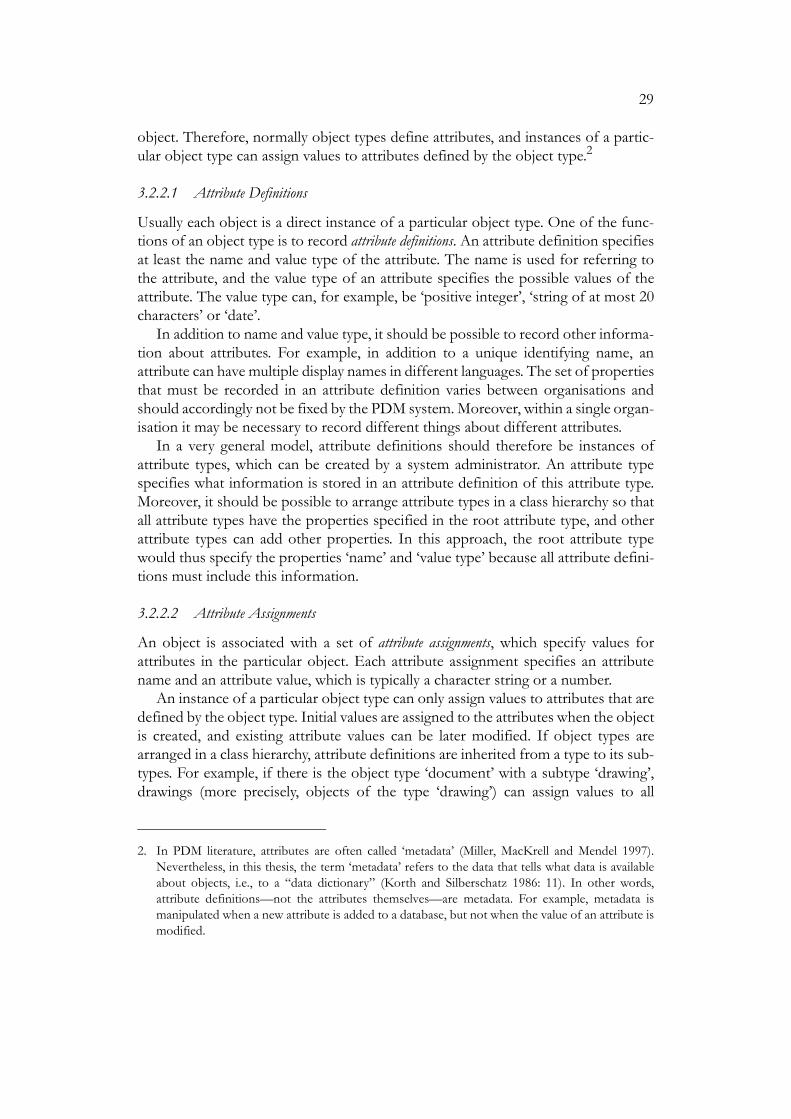
object. Therefore, normally object types define attributes, and instances of a partic-ular object type can assign values to attributes defined by the object type.2
3.2.2.1 Attribute Definitions
Usually each object is a direct instance of a particular object type. One of the func-tions of an object type is to record attribute definitions. An attribute definition specifiesat least the name and value type of the attribute. The name is used for referring tothe attribute, and the value type of an attribute specifies the possible values of theattribute. The value type can, for example, be ‘positive integer’, ‘string of at most 20characters’ or ‘date’.
In addition to name and value type, it should be possible to record other informa-tion about attributes. For example, in addition to a unique identifying name, anattribute can have multiple display names in different languages. The set of propertiesthat must be recorded in an attribute definition varies between organisations andshould accordingly not be fixed by the PDM system. Moreover, within a single organ-isation it may be necessary to record different things about different attributes.
In a very general model, attribute definitions should therefore be instances ofattribute types, which can be created by a system administrator. An attribute typespecifies what information is stored in an attribute definition of this attribute type.Moreover, it should be possible to arrange attribute types in a class hierarchy so thatall attribute types have the properties specified in the root attribute type, and otherattribute types can add other properties. In this approach, the root attribute typewould thus specify the properties ‘name’ and ‘value type’ because all attribute defini-tions must include this information.
3.2.2.2 Attribute Assignments
An object is associated with a set of attribute assignments, which specify values forattributes in the particular object. Each attribute assignment specifies an attributename and an attribute value, which is typically a character string or a number.
An instance of a particular object type can only assign values to attributes that aredefined by the object type. Initial values are assigned to the attributes when the objectis created, and existing attribute values can be later modified. If object types arearranged in a class hierarchy, attribute definitions are inherited from a type to its sub-types. For example, if there is the object type ‘document’ with a subtype ‘drawing’,drawings (more precisely, objects of the type ‘drawing’) can assign values to all
2. In PDM literature, attributes are often called ‘metadata’ (Miller, MacKrell and Mendel 1997).Nevertheless, in this thesis, the term ‘metadata’ refers to the data that tells what data is availableabout objects, i.e., to a “data dictionary” (Korth and Silberschatz 1986: 11). In other words,attribute definitions—not the attributes themselves—are metadata. For example, metadata ismanipulated when a new attribute is added to a database, but not when the value of an attribute ismodified.

30
attributes that are defined for all objects and documents in addition to the attributesdefined specifically for drawings.
If the attribute definition in an object type specifies the attribute as compulsory, allinstances of the type must assign a value to the attribute; if the attribute is optional, anobject can leave the attribute unassigned (or assign a null value, which usually meansthe same).
3.2.2.3 Attribute Value Types
The value type of an attribute specifies what kind of values can be assigned to theattribute. Simple value types include integers, character strings and dates. It is oftennecessary to specify the allowed values for an attribute more precisely than by sayingthat the value must be any number or any string of at most a particular number ofcharacters. In many systems it is possible to create value lists and specify that a par-ticular attribute can only be assigned values from a particular value list.
Sometimes the value of an attribute must be of a particular form, such as two let-ters followed by a hyphen and three digits. This kind of constraint on attribute valuescan for example be described by means of a regular expression (Aho and Ullman1977: sec. 3.3). In more complex cases it is necessary to a write a piece of programcode to check the attribute value. Section 11.4 shows an example of this kind ofmechanism.
It is useful if an attribute can also record a set or list of individual values instead ofa single value. For example, a document can have an attribute that records the namesof users who should be notified when new versions of the document are available, ora product can have a list of market areas as an attribute. Moreover, it should be pos-sible to define attributes that store much larger pieces of data than a single integer ora relatively short character string. For example, it may be useful to have an attributethat stores a bitmap picture or even moving video data.
The allowed values of an attribute in an object may also depend on the values ofother attributes in the object and other data in the database. In this case the routinesthat check attribute values are not necessarily associated with individual attributes.Instead, a single routine may check the values of a group of mutually dependentattributes. Whether an attribute is compulsory or optional may also depend on thevalues of other attributes.
If relations are represented by means of attributes, there are also attributes thathave references to other objects as values. Relations and alternative possibilities fortheir representation are discussed in section 3.2.3.
3.2.2.4 Default Values
It should be possible to specify a default value in an attribute definition. The defaultvalue is assigned to the attribute when a user creates a new object without assigningany value to the attribute.3 If the attribute definition in an object type definition sim-ply includes a specific default value, all objects of this type have the same default value

31
for the attribute. In more elaborate cases the default value again depends on the val-ues of other attributes. The default value may also depend on the user who is creatingthe object. For example, suppose that each document is assigned to a particulardepartment of the company. The default value for the corresponding documentattribute could be the department of the user who creates the document.
3.2.2.5 Derived Attributes
If there is a mechanism for computing a default value for an attribute from otherattribute values and other data, the same mechanism can also be used for derivedattributes. The value of a derived attribute is computed from other data in the data-base. To ensure the correct value of a derived attribute, users are typically not allowedto assign values directly to the attribute.
There are basically two ways to handle derived attributes. One possibility is tocompute the value each time the value is needed; the attribute value is not stored inthe database at all. The view mechanism of relational databases is an example of thisapproach (Korth and Silberschatz 1986: sec. 3.5). The other alternative is to store theattribute value in the database and assign a new value to the attribute whenever thecontents of the database change so that the value of the derived attribute needs to bechanged, too. The latter method is usually more efficient (at least assuming that thevalue of the derived attribute is read more than once before the value changes). Nev-ertheless, if the value of the derived attribute is computed in a complex way, it maybe difficult to ensure that the attribute is updated properly by all database operationsthat affect the attribute. Section 11.5 shows an example of a stored derived attribute.
Attributes in a PDM system may correspond to data in other systems. At worst,data from one system must be manually re-entered in another system. For example,some attributes that a PDM system stores for drawings may directly correspond todata stored in the drawings by the CAD tool. In this case the CAD tool must be inte-grated with the PDM system so that attribute values are automatically transferredbetween the systems.
3.2.2.6 Read-only Attributes
Attributes can be used for representing data that cannot be modified by users, or atleast not with explicit attribute assignments. For example, suppose each objectrecords its creation time. The creation time can be represented as an attribute thatcan be read by users in the same way as other attributes but cannot be assigned a newvalue. As another example, suppose that objects also record their last modificationtimes. This data could be stored as an attribute that can again be read by users butcan be assigned by the system only.
3. Alternatively, one can say that an attribute has a default in an object that does not assign a valueto the attribute.

32
3.2.2.7 Attribute Refinements
If an object type inherits an attribute from a supertype, it should be possible to refinethe attribute in the subtype. Typically an attribute refinement changes the value typeor the default value of an attribute.
An object type can refine the value type of an attribute defined in a supertype. Forexample, suppose the object type ‘document’ defines an attribute with a list ofallowed values. The object type ‘drawing’, which is a subtype of ‘document’, canrefine the attribute value type by further restricting the list of allowed values. A sub-type cannot extend the attribute value type; for example, the attribute in a drawingcannot be assigned a value that would not be allowed in a document.
If an object type inherits multiple refinements for an attribute, the “effective”value type of the attribute in the object type is the “intersection” of all value types.For example, figure 4 shows object type A, which defines attribute ‘i’ with the valuetype ‘integer’. Subtypes B and C refine the value type as ‘integer greater than 100’ and‘even integer’. Object type D, which is an immediate subtype of both B and C, has‘even integer greater than 100’ as the “effective” value type for the attribute.
An attribute refinement can also specify a new default for an inherited attribute.For example, if both the object type ‘document’ and the object type ‘drawing’ definea default value for an attribute, the default value defined by the object type ‘drawing’is used for all drawings. Multiple inheritance obviously poses a problem if conflictingdefault values are inherited from two immediate supertypes. One possibility is tospecify that in this case the subtype itself must define a default value for the attribute.
Figure 4. Attribute refinement
Ai : integer
C{ i mod 2 = 0 }
B{ i > 100 }
D
Effective constraint in D: (i > 100) and (i mod 2 = 0)

33
3.2.3 Relations
So far the discussion has mainly concerned data that is attached to individual objects.For example, products and documents have attributes. Nevertheless, there are alsorelations between objects. Below are some examples, which are discussed in moredetail in other sections.
• Relations between a product and its components (section 3.3.1).
• Relations between products and connected documents (section 3.4).
• Relations between an object and its versions, and between versions (section 3.5).
• Relations between interdependent objects (section 4.5).
In the same way that a PDM system should make it possible to create new objecttypes (e.g., a new document type), the system should allow the creation of new rela-tions. The definition of a new relation must at least specify the name of the relation,the types of objects that can participate in the relation, and the cardinality of the rela-tion. For example, if a particular relation between products and documents has thecardinality ‘[0..1]-[0..*]’, each product can be related to many documents, and eachdocument can be related to at most one product.
There are various ways to represent relations between objects. As an example,suppose there is a relation between documents and products.4
One possibility is that objects have reference attributes. The definition of a refer-ence attribute specifies an object type, and the value of the attribute is a reference toan object of this type or a set of references to objects. In the previous example, doc-uments could include an attribute of the type ‘reference to a product’, and corre-spondingly products could include an attribute of the type ‘set of references todocuments’. This representation of relations is simple because reference attributescan be treated in much the same way as other attributes.
Nevertheless, there are also good reasons for representing relations as “first-classentities” instead of using reference attributes (Rumbaugh 1987). This approach usestwo kinds of entities: objects and relationships. Each relationship entity is an instanceof a relation type in the same way that objects are instances of object types. Each rela-tionship records references to the related objects. In the case of a relation betweenproducts and documents, each related ⟨product, document⟩ pair would thus be rep-resented as a relationship that contains a reference to one product and one docu-ment.
To some extent the choice between representing relations with attributes or rela-tionship entities is only a matter of implementation techniques. Nevertheless, onlyrelationship entities make it possible to add attributes to the relationships. For exam-
4. Note that the term ‘relation’ is defined in mathematics as a subset of the Cartesian product of therelated sets. In the example, the relation would thus consist of all related ⟨product, document⟩-pairs. An individual pair of a relation is here called a ‘relationship’.

34
ple, consider the ‘has-part’ relation between components. An individual relationshipcould for example tell that component X has component Y as a part. The positionand orientation of Y with respect to X could be stored as an attribute of the relation-ship because this data is associated with the particular combination of two compo-nents, not with either of the components.
3.3 Products
The term ‘product’ is ambiguous in more than one way. Firstly, consider the hierar-chical breakdown structure of product, such as a car and its engine. From a cus-tomer’s point of view the car is a product whereas the engine is only a component ofthe product. On the other hand, typically similar PDM functions are needed for both“top-level products” (e.g., the car) and “components” (e.g., the engine). It is thereforerather irrelevant whether items at all levels are called products or components. Thisthesis mainly uses the term ‘component’. When a component is said to consist ofsubcomponents, the component with subcomponents can also be a complete prod-uct. It is possible to make another choice. For example, Part 41 of the STEP standard(section 6.1.3.1) only uses the term ‘product’, and consequently a product can becomposed of other products (ISO 1994d: sec. 2.3.4.1).
Secondly, suppose I have bought a car of the same make and model as my friend.Have we bought the same product? The answer is positive if the term ‘product’ isunderstood to refer to the product design which can be manufactured in multiplecopies. On the other hand, my car and my friend’s car are two separate products ifthe term refers to the actual physical products.
One area where this distinction becomes obvious is the life cycle of a product. Thelife cycle of a physical product extends from manufacture to demolition and recyclingwhereas the life cycle of a product design begins with some initial concept for a newproduct and ends when the design is taken away from production and the existingphysical products can in effect be “forgotten”. The last comment refers to the factthat the manufacturer must often provide spare parts and other after-sales serviceseven when the product is no longer manufactured.
Thirdly, consider a configurable product, which allows some degree of customer-specific variation (section 3.3.2). Again, ‘product’ can mean either a generic productwith all the allowed variation, or a specific product that has been configured for a par-ticular customer order.
The differences between a car design and an individual car, and between a config-urable product and its variants are similar because they both deal with the distinctionbetween a product type and its instances. A physical product is an instance of a prod-uct design, and a product configuration is an instance of a configurable product.Depending on the context, the term product can refer either to a type or one of itsinstances.
The term ‘product’ is so generic that one should not try to reserve one of its pos-sible meanings as the “correct” one. When products are discussed in a more specific

35
context, such as in a particular data model or PDM system, the term must be definedmore precisely. Even then it may be better not to select arbitrarily a particularrestricted meaning for the term. Instead, other terms, such as ‘product family’ and‘product variant’ in chapter 9, should be defined with more precise meaning.
This thesis mainly deals with physical, manufactured products. To some extent theconcepts are also applicable to non-physical products. For example, most of theissues discussed by Cagan (1995) in connection with software configuration manage-ment are valid for PDM, too.
3.3.1 Product Structures
One of the fundamental properties of virtually any product is a hierarchical productbreakdown structure, which describes how the product is divided into components,which are in turn divided into subcomponents, etc. In this thesis, the term ‘productstructure’ refers to this hierarchical arrangement of the components of a product.Another commonly used term is bill-of-material (BOM). The STEP standard dis-cussed in section 6.1 further distinguishes between the BOM structure and the partslist structure of a product. This distinction, however, is not in general use.
The important question of component versions in product structures is addressedtogether with versioning in section 3.5.6.
3.3.1.1 Parts and Components
This thesis refers to the hierarchical connection between components by saying thata component has another component as a part. Moreover, a component is said to real-ise a part in another component. For example, a bicycle can have the parts ‘frontwheel’ and ‘back wheel’, both of which can be realised with the same kind of com-ponent. The distinction between components and parts becomes especially impor-tant in section 3.3.2 in connection with configuration models. A configuration modelcan, for example, specify that a particular part can be realised with either of two alter-native components.
To illustrate the difference between a part and a component that realises the part,one can also regard a part as a “slot” that can be “filled” with an appropriate compo-nent. The name of the part is an identification for the “slot”, and the name of a com-ponent is an identification for the component that “fills” a particular slot in aparticular component. One can also say that a part, such as the front wheel of a bicy-cle, defines a role, which is played by the component that realises the part.
The product structure is sometimes also referred to as the has-part relation. Ifcomponent X has component Y as a part, one can say that X and Y are relatedthrough the ‘has-part’ relation.
Note that sometimes the term ‘part’ is used quite differently. For example, in thedraft ISO standard on Part Libraries, discussed in section 6.2, a part corresponds towhat is called a component in this thesis, and a component in the standard is a part

36
on the “lowest” level of a product structure, i.e., a component cannot be decomposedinto further components.
Some models define a fixed number of product structure levels with differentnames. For example, the American military standard MIL-STD-280A defines the fol-lowing eight item levels: system, subsystem, set, group, unit, assembly, subassemblyand part (Buckley 1996: 10, 270). Each level is given a different definition, but thedefinitions are so vague that one wonders whether it is really possible to assign thecomponents of a product to these levels. The fixed number of levels also seems arbi-trary; why not seven or nine levels instead of eight?
Components, like all objects, are instances of object types. One important ques-tion is how parts relate to component types and instances. A component type definesattributes, and an instance of the component type assigns values to the attributes.Should parts be treated in a similar way so that a component type defines parts, andan instance of the component type realises the part with other component instances?
This approach is taken for configurable products in section 3.3.2. A single config-urable product is represented with a component type. The instances of the type aresimilar in the sense that all instances have the same parts but different in the sensethat in different instances of the type the parts are realised by different componentinstances. As a result there is a large number of component types because every com-ponent with different parts requires its own component type.
Nevertheless, it is not always necessary to represent parts in such detail. Alterna-tively, a component type does not define any parts. A component instance can thenhave any parts regardless of the component type. This approach is typically used insystems that do not support configurable products or generic product structures.
3.3.1.2 Multiple Structures and Views
Thus far the discussion has referred to the product structure of a product, implyingthat each product would have a single breakdown structure. Nevertheless, this is notnecessarily true. For example, a product can have separate manufacturing and main-tenance structures. These different structures are sometimes referred to as views (vanden Hamer and Lepoeter 1996).
A simple approach to multiple views is that a product has a single breakdownstructure, and each component in this structure can be associated with multiple viewsof the component (Cleetus 1995). The problem with this approach is that all viewsof a single product have the same breakdown structure.
If different views of a product should have different structures, a simply solutionis to assume that a product has a single “complete” structure. The different viewsonly display different parts of this structure by filtering out unwanted data.
In general, however, a product can have multiple “truly” different structures,which cannot be created with filters from any single “master” structure. As all thestructures still represent different aspects of the same product, there must be a mech-anism for saying that particular components in two views are related in a particularway, for example by corresponding to the same physical component. The model

37
described by Katz (1990) represents this information with structural objects calledequivalencies.
3.3.1.3 Shared Components
One issue with product structures is the question of shared components, i.e., thequestion whether a single component can realise multiple parts. Here it is importantto understand the level on which things are shared.
It is clearly possible to share component descriptions. A physical product consistsof physical components, which are described by some kind of component objects inthe PDM system. A component object can be shared so that two physical compo-nents are described by the same component object. This means that the physicalcomponents are identical with respect to the properties that are represented with thecomponent objects in the PDM system.
Consider a product with “identical” components. While the components arebeing designed, they are described by a single component object. However, when theproduct is manufactured, it may be necessary to give the components their own“identities” by describing them with two separate component objects. These objectscan store data that is applicable to individual components, such as maintenance his-tories.
What is not so clear is whether there is ever the need for truly shared components.In other words, can a single physical component realise two parts at the same time?If the parts of a product represent functions that must be fulfilled by physical com-ponents, a single component can fulfil two functions and thus realise two parts. Nev-ertheless, in this case it may be more appropriate to introduce functions and theirrelations with components as altogether new concepts.
3.3.2 Configurable Products
Companies are becoming increasingly interested in configurable products, which can beadapted individually for customer requirements (Tiihonen et al. 1996). A configura-ble product represents a set of different but closely related product variants. All variantsof a configurable product can also be called a product family. All possible variants of aconfigurable product are described with a configuration model or a generic product structure(Erens 1996: sec. 4.3), which mean more or less the same.
Figure 5 illustrates two paths that can lead a company towards configurable prod-ucts. First, a company can originally be making non-configurable standard products.The company has a fixed range of products that are first designed and then manufac-tured in large numbers. The production can be made efficient because all “instances”of the product are identical. Many companies, however, want to increase their com-petitiveness with configurable products, which means that the customers can buyproducts that have been adapted individually, within some limits, to their needs.
The second path to configurable products starts from individually designed one-of-a-kind products. These products cater very well for the needs of customers, but

38
the individual design and engineering work involved in each product order is expen-sive. Companies with these products want to reduce costs by eliminating some of thecreative, and expensive, engineering needed for individual product deliveries.
Few of the current PDM systems can manage configurable products. Althoughthere are many separate configurator tools (Haag 1998; Richardson 1997), the addi-tional functionality needed for configurable products is so closely connected with theother functions of PDM systems that support for configurable products should beincluded directly in a PDM system.
Although a PDM system should provide support in the management of config-urable products, it is important to understand that the configurability of a product isbased on the product itself, not on any information system. Usually this means thatthe product must have a modular structure so that a particular variant of the productcan be created by combining a suitable subset of the available modules.
This section defines fundamental concepts for configurable products. The con-cepts and terms are based on the work in the Product Data Management Group (Pel-tonen et al. 1998).
3.3.2.1 Configuration Process
Although this chapter of the thesis deals with data models, the presentation of thedata model for configurable products must begin with a brief description of the proc-esses that provide the context for the data model.
The variants of a configurable product are constructed individually for each cus-tomer order from predefined components on the basis of an order specification anda predefined configuration model.
Figure 5. Two paths to configurable products
level of variation highlow
cost
low
hig
h
mass product
configurable product
one-of-a-kind product

39
As noted earlier, the distinction between products and components is not impor-tant in this thesis. In the definition above, a product is not necessarily an end-productsold to customers. The product can also be a component within a larger product, andthe customer can for example be a manufacturing or assembly unit within the sameor in another company. Although this section, like most of the thesis, is written interms of physical, manufactured products, a configurable product can also be a serv-ice or other immaterial good, such as an insurance policy.
Figure 6 illustrates the sales-delivery process that is carried out for each customerorder, leading from customer requirements to the physical products that are manu-factured for the customer. This section mainly deals with the configuration process,which is one part of the whole sales-delivery process.
The input to the configuration process is an order specification, which is a formal rep-resentation of customer requirements. The specification is created by sales personnel,possibly in a computer-assisted sales configuration process, which may be similar tothe configuration process described here.
The configuration process is controlled by a configuration model. The configurationmodel of a configurable product describes all the possible variants of the product andspecifies how to create an appropriate variant for a given order specification or atleast how to check whether a given variant conforms to a given specification.
The configuration process generates a configuration, which is a description of thespecific product variant that will be manufactured for the particular order. The con-figuration is said to be based on the configuration model that controls the configu-ration process. As illustrated in the figure and explained later in the text, it is assumedhere that the order specification is actually stored as part of the configuration.
A configuration does not only represent the final outcome of the configurationprocess but also its intermediate stages (Peltonen et al. 1994b). A configuration is cre-ated at the beginning of the process, and during the process the configuration recordswhat is known about the product variant. In general a configuration thus representsmany possible product variants. During the configuration process, which is ofteniterative, the configuration becomes more and more detailed representing fewer andfewer variants. Finally the configuration becomes a specific configuration, which repre-sents a single variant.
Before the product is actually manufactured, one creates an individual description ofit. Each individual description corresponds to a single physical product and containsadditional information that is needed and created during the manufacturing process.An individual description can for example record the serial number and the mainte-nance history of a physical product.
Later a configuration may become subject to reconfiguration. This refers to a situa-tion in which an individual configuration must be modified to satisfy new customerrequirements. In general, reconfiguration is more difficult than configuration becauseone must not only consider the desired outcome of a configuration process but alsofind the most suitable (least expensive, fastest, etc.) way to reach this state by modi-fying the existing configuration.

40
3.3.2.2 Explicit Structure
There are many different approaches to configurable products (Sabin and Weigel1998). When configurable products are included in a PDM system, it seems best touse a conventional hierarchical product structure as the basis for the description of aconfigurable product. A configuration model is therefore divided into an explicit struc-ture and constraints (Männistö, Peltonen and Sulonen 1996). Explicit structures arediscussed here, and constraints in section 3.3.2.4.
Figure 6. Configuration process
customer
salesconfigurationprocess
order specification
configuration #123 at time T0
order specification
configuration #123 at time T1
structure
order specification
configuration #123 at time T2
structure
configuration model
productdevelopmentprocess
singleconfiguration
for a singleorder at
different timesduring the
configurationprocess
specific configuration
configuration #123individual #1
individualdescriptions
configuration #123individual #2
physical product physical product
configurationprocess
manufacturingprocess

41
To represent configurable products, product structures must be extended withconcepts like optional and alternative parts and parametric components. A part isoptional if the part need not be realised by any component. An alternative part doesnot need to be realised with a particular kind of component. Instead, the part hasmultiple alternatives for its realisation. A parametric component has parameters,which must be given values during the configuration process. Typical parametersinclude the colour or physical dimensions of a component.
So far it has been assumed that there are relatively few component types. Forexample, there could be a type for standard components bought from outside thecompany, another type for components manufactured by the company itself, etc.There can be a class hierarchy of component types, but in any case the number ofcomponent types is assumed to be in the order of tens rather than hundreds. The setof component types is quite static. Although new instances of the component typesare created constantly, a new component type is created only when there is a need torepresent components that have attributes different from other components and thatmust be processed somehow differently.
Accordingly, in the discussion on product structures in section 3.3.1, the ‘has-part’relation was established between component instances. In other words, a componentinstance has other component instances as parts. The difference between a referenceto a component (instance) and a reference to a component version is ignored herebut will be brought up later.
In configurable products, however, component types play a more important role.For example, a parametric component is represented with a component type thatdefines attributes for the parameters of the component. Whereas an ordinary prod-uct structure records ‘has-part’ relationships between component instances, a com-ponent type in a configuration model has other component types as parts. Moreprecisely, a component type can specify that a valid instance of the type has a partthat must be realised with an instance of a particular component type.
The explicit structure of a configuration model can, for example, be built with thefollowing concepts:
• A configuration model defines component types, which are arranged in a classhierarchy. It should be possible to use multiple inheritance.
• A component type can define attributes.
• A component type can define parts. A part definition specifies the following prop-erties:
• Part name. Part name makes it possible to refer to a part independently of thecomponent type or types that can realise the part.
• Allowed component types. The part can be realised with instances of any of theallowed types.

42
• Cardinality. The cardinality of a part tells the allowed number of instances thatcan realise the part. The can be specified, for example, as an integer range or aset of ranges. A part is optional if its cardinality includes zero, in other words,if “no components” is an allowed realisation for the part.
• One of the component types is designated as a configuration type. The configurationas a whole is represented as a configuration instance, which is an instance of theconfiguration type or its subtype. Other components of the configuration aredirect and indirect parts of the configuration instances.
If the cardinality of the part makes it possible to realise the part with multiple com-ponent instances, and there are multiple allowed component types, it is further nec-essary to specify whether all components in the realisation of the part must be of thesame type or whether it is possible to mix instances of different allowed componenttypes in a realisation of the part.
In addition to the explicit structure, configurable products can also be describedwith other constructs, such as components with ports that must be connected toother ports (Mittal and Frayman 1989). This approach, which is not discussed furtherin this thesis, emphasises the physical and other connections between components;the hierarchical breakdown structure of the product is more or less implicit.
3.3.2.3 Configuration Questions and Completeness
This section introduces the concept of configuration completeness, which is one nec-essary condition for a specific configuration. One way to illustrate completeness andother properties of configurations is to think of the explicit structure of a configura-tion model as “asking questions” that must be answered during a configuration proc-ess. For example, an optional part in the explicit structure asks if the component isincluded in the configuration; an alternative part asks which alternative is chosen; anda parametric component asks what values are given to the parameters.
The explicit structure of a configuration model asks questions, and the answersare recorded in a configuration that is based on the configuration model. As the con-figuration gradually becomes more detailed during a configuration process, in termsof questions and answers this means that the configuration answers an increasingnumber of questions. A configuration that answers all the questions asked by the con-figuration model is a complete configuration.
Note that all questions of an explicit structure do not necessarily have to beanswered during each configuration process. Some questions are “activated” only ifother questions are answered in a particular way.
The questions and answers must only be understood as a metaphor for explainingcompleteness and other concepts related to configuration models and configura-tions. The explicit structure is still represented as an extended bill-of-material, not asa set of questions.

43
3.3.2.4 Constraints
The explicit structure of a configuration model defines a large number of differentpossible complete configurations. Typically not all of them can be accepted as spe-cific configurations resulting from a configuration process. A complete configurationcan, for example, be disallowed because it represents a product variant that cannotbe built for technical reasons. The marketing policy of a company may also dictatethat certain variants are not sold although there are no technical reasons against it.For example, a car may not be available with a leather interior in combination with asmall engine.
Since all complete configurations are not acceptable as specific configurations, aspecific configuration must be both complete and valid. A configuration modeldefines the validity criteria as constraints. Constraints are conditions that can be evalu-ated in a configuration and none of which is false in a valid configuration.
The result of evaluating an individual constraint in a configuration is true, false orunknown. The result can be unknown in an incomplete configuration that does notyet answer a question that the constraint refers to. If a constraint evaluates to true orfalse in a particular configuration, the configuration is said to satisfy or to violate theconstraint, respectively. If the value is unknown, the configuration neither satisfiesnor violates the constraint.
These definitions allow all combinations of completeness and validity. For exam-ple, if a configuration is incomplete and valid, all questions of the explicit structurehave not yet been answered, but the answers given so far violate no constraints.
3.3.2.5 Order Specifications
In this section it is assumed that it is possible to distinguish between an order speci-fication, which serves as input to a configuration process, and the structure of a con-figuration, which represents the output from the process. This distinction ismeaningless for products that are configured without a formal order specification.Their structure is built gradually during the configuration process, and the inclusionof a particular component, for example, can sometimes be “input data” and some-times “output data” determined by other “input data”.
If, however, the product has an order specification, the relations between thespecification and the configuration are also defined with constraints, which are herecalled implementation constraints because they specify how different specificationsshould be “implemented” by means of different configurations. For example, a com-puter could be associated with an implementation constraint saying that if the cus-tomer wants to run a particular application on the computer, the computer must haveat least a particular amount of memory.
To write formal implementation constraints, the description of a configurableproduct must specify the allowed form for an order specification that can be used asinput to a configuration process. For example, a configurable computer could be

44
associated with a set of applications and the order specification could contain somesubset of this set.
One way to organise configuration models and order specifications is to includethe implementation constraints and the description of the order specification in theconfiguration model. The order specification itself is part of a configuration, as wasillustrated in figure 6.
Earlier a configuration was said to contain information for the manufacture of aproduct variant. If the configuration also contains the order specification, a specificconfiguration based on a particular configuration model represents an acceptablevariant of the configurable product that also conforms to the order specificationincluded in the configuration.
There can be many specific configurations for a given configuration model and agiven order specification. In this case one of the specific configurations is selectedfor manufacturing on the basis of some criterion, such as an optimality criterion onprice or delivery time. If possible, the criterion should of course be included in theconfiguration model so that the model does not accept multiple specific configura-tions for any order specification.
3.3.2.6 Constraint Classes
It is now necessary to elaborate on the division of a configuration model into anexplicit structure and constraints. A configuration model consists of an order speci-fication description, an explicit structure and constraints. The constraints are furtherdivided into three classes according to whether they refer to the order specification,to the explicit structure or to both.
• Specification constraints refer to the order specification only. In other words, specifi-cation constraints define the criteria for checking the validity of an order specifi-cation that is going to be used as input in a configuration process. It is useful ifthe product, its configuration model and the configuration process can bedesigned so that a valid order specification always leads to a specific configuration.
• Implementation constraints refer to both the order specification and the explicit struc-ture. They thus define the criteria for checking whether the structure of a givenconfiguration implements the specification of the configuration.
• Structural constraints refer to the explicit structure only. They define the criteria forchecking whether the configuration as such represents a product that the com-pany is able or willing to manufacture without considering any order specification.
The completeness and validity of a configuration must be redefined similarly. A con-figuration can thus be separately complete with respect to the order specification andthe structure. It is also possible to check separately whether a configuration is validwith respect to each of the three constraint groups.

45
3.3.2.7 Abstract Component Types in Configuration Models
When the distinction between abstract and concrete component types was intro-duced in section 3.2.1.4 it was said that all component instances must be instances ofconcrete component types. An instance of an abstract type does not make sense inan ordinary product structure, which does not involve any notion of configuration.Nevertheless, a configuration of a configurable product can reasonably contain aninstance of an abstract component type during a configuration process.
For example, consider figure 7, which shows component types that represent dif-ferent kinds of computers. In this figure the “leaf” component types, i.e., ‘businesscomputer’, ‘entertainment computer’ and ‘educational computer’ are concrete, andthe component types without subtypes are abstract.
This means that a product delivered to a customer must be a business computeror either of the home computer models. One cannot simply order a computer or ahome computer without specifying a particular kind of computer. The componenttypes ‘computer’ and ‘home computer’ thus describe the general properties of allcomputers and of all home computers, respectively. They do not specify a product in“sufficient detail” in the same way as the component type for the business computerand the component types for the two specific home computer models.
In terms of questions asked by an explicit structure one can say that the compo-nent type ‘entertainment computer’ is concrete because the component type(together with its supertypes) asks all questions that need to be answered in a config-uration process to make a specific product variant. A concrete component type alsocontains all necessary constraints for checking the validity of the answers. Theabstract component type ‘home computer’ on the other hand asks “too few” ques-tions; even when all questions have been answered, there is not enough informationto serve as output from a configuration process.
A configuration can contain instances of abstract component types during a con-figuration process. For example, suppose a computer is being configured. The con-
Figure 7. Component type hierarchy
computer
business computer
entertainment computer educational computer
home computer

46
figuration can first contain an instance of the abstract component type ‘homecomputer’, which tells that the computer is going to be some kind of home computer.Later during the configuration process the component instance must be changed tobe an instance of a concrete component type, such as ‘entertainment computer’.
A specific configuration, which is the output from a configuration process, wasearlier required to be both complete and valid. The third and final requirement for aspecific configuration is that all its components are instances of concrete componenttypes.
3.3.2.8 Part Refinement
Section 3.2.2.7 already showed how a component type can refine attributes definedin its supertypes. Similarly, a component type can refine parts. As an example, con-sider figure 8, which shows the component types ‘car’, ‘bus’, ‘engine’ and ‘dieselengine’. The component types ‘bus’ and ‘diesel engine’ are subtypes of ‘car’ and‘engine’, respectively. The component type ‘car’ specifies that it has a part ‘engine’ ofthe component type ‘engine’. The component type ‘bus’ is a subtype of ‘car’, andaccordingly can refine the part by specifying that the part must be of the type ‘dieselengine’, which is a subtype of ‘engine’. In summary, each car has some kind of engine,a bus is one kind of a car, a diesel engine is one kind of an engine, and a bus has adiesel engine.
In the previous example the component type of the engine part was refined whenone moved from component type ‘car’ to its subtype ‘bus’. Parts can also be refinedduring a configuration process. For example, the configuration for a bus may origi-nally specify the engine to be simply a diesel engine. Later during the configurationprocess the part is refined to a subtype of the diesel engine. Typically both ‘engine’and ‘diesel engine’ would be abstract component types. In a specific configuration thepart must have been refined to a concrete component type.
The configuration instance, which represents the configuration as a whole, can berefined in the same way as any of its parts. This means that a configuration that is
Figure 8. Part refinement
bus
car
diesel engine
engineengine
enginepetrol engine

47
originally an instance of one component type can change during a configurationprocess to be an instance of a subtype of the original component type.
The discussion above dealt with the refinement of a part from a component typeto one of the subtypes. A part can also be replaced with an instance of a supertype,which is an example of “backtracking” during a configuration process.
3.3.2.9 Validation and Generation
The constraints are a mechanism for specifying the validity conditions for a configu-ration. Nevertheless, a PDM system that supports configurable products shouldobviously do more than just check the validity of a configuration that the user hassomehow created.
Some constraints can be solved automatically. In other words, given a set of con-straints, one can automatically derive a procedure that generates a configuration thatsatisfies the constraints (Shah and Mäntylä 1995: sec. 8.3.3). Nevertheless, many con-straints in actual configurable products are too complex to make constraint program-ming a general solution to product configuration.
It is therefore necessary to draw a distinction between the validation and generationof a configuration. A configuration is validated with constraints, and generated withprocedures. A procedure can employ various techniques, including conventional pro-cedural language, logic programming and, in some cases, constraint programming. Aprocedure can also be an external program, which is started by the configuration toolwith input values derived from the answers already available in the configuration andwhich adds new answers to the configuration.
Sometimes it is difficult to separate validation and generation. For example, sup-pose part of the configuration is generated with an external stress analysis program.It seems impossible to associate this procedure with a more meaningful validationconstraint than with one that checks that the current output values have been com-puted from the current input values with the correct program.
3.4 Documents
To a large extent product data is represented as documents, which are created andmanipulated with specific tools. Although document management is one of the mostimportant functions of a PDM system, this section on document management israther short because document versioning in discussed separately in the next sectionand document management is the main topic of the second part of the thesis.
Most documents in a manufacturing company are connected to products. Typicalexamples of documents include drawings manipulated with a CAD tool and manualsmanipulated with text processors and desktop publishing tools. A document may nothave any direct representation on paper. For example, a 3-D solid model can also beregarded as a document related to a product.

48
The connection between products and documents is many-to-many. A singleproduct can have many connected documents, and a single document can be con-nected to many products. For instance, a number of similar related products canshare a common service manual. There can also be documents that are not connectedto any product. For example, quality handbooks and other documents that describegeneral procedures within a company are not connected to products.
Sometimes one distinguishes between drawings and other documents (Buckley1996: sec. 8.2). This distinction seems to be motivated by the convention that eachproduct is closely associated with a “main drawing”, which can include other infor-mation in addition to a graphical description of the product. For example, the partslist of a product with a particular identification may be found on a drawing with thesame identification as the product. In this thesis, however, drawings are not distin-guished from other documents. Other information, such as the parts list, is assumedto be associated directly with the product.
In everyday speech, a document is usually understood as a file that can be openedand manipulated with a document tool, such as a word processor. Nevertheless, in aPDM system, a document is a more abstract object. For example, in the systemdescribed in the second part of the thesis, a document is a hierarchical structure ofdocument versions, subdocuments and other entities. Moreover, a document, its ver-sion, etc., have attributes, which are typically managed by the PDM system only andare not seen by the document tools. In this thesis the “actual document”, which ismanipulated with a document tool, is called a document file.
Today virtually all documents are available in digital form. The actual document(i.e., a document file) is thus also stored in a PDM system. Companies often also haveold drawings and other documents on paper only. These documents can be scannedinto digital form and stored in the database, or the database can contain only a refer-ence to the paper copy.
A PDM system typically treats a document file simply as a binary file, i.e., as anarbitrary sequence of bytes. This means that the system can store any kind of docu-ment, which must be manipulated with a separate document tool (see tool integrationin section 5.5.1).
Usually a document file is the smallest unit manipulated with a PDM system. Nev-ertheless, a document file can have a further internal structure. A text file, for exam-ple, can consist of chapters, subsection, paragraphs, figures, etc. Similarly, a drawingcan consist of assemblies, components, lines, points, etc. The fact that the PDM sys-tem does not “understand” the contents of a document file at this level is not a seri-ous problem if the document files are self-contained in the sense that the relationsbetween different components of a document file are always within a single docu-ment file. For example, consider a text file that contains a figure. There is no problemif the figure is embedded in the file so that the figure is stored as part of a single file.
Nevertheless, it is also possible that the figure is stored as a separate document oras a separate document file within the same document, and the text file only containsa link to the figure file. Moreover, the same figure can be used in many documents,

49
all which contain a link to the same document. These links between documents (ordocument files) should also be known by the PDM system. For example, the systemshould prevent a user from deleting the figure as long as there are other documentswith a link to it.
It is difficult for a PDM system to determine these kinds of relations between doc-uments, especially if the documents are stored in the proprietary formats of the toolprograms. The problem becomes somewhat easier if documents are stored in a struc-tured and standardised format, such as SGML or XML (Light 1997).
It is usually assumed that products and other “abstract” entities serve as the main“access points” to product data in a PDM system. The products can then providelinks to associated drawings and other “concrete” documents. However, Dong andAgogino (1998) describe an alternative approach, in which a CAD program and CADdrawings are the primary interface to engineering data. In their system, the graphicalentities in a CAD drawing can contain links to data in a relational database systemand to other documents stored in a document management system. The system thusrelies heavily on documents, or “smart drawings” as they are called in the system.
The use of CAD drawings as a basis for an engineering data system may make thesystem easier to use because of its concreteness and the familiarity to engineers whomainly work with drawings. On the other hand, one wonders how convenient thedocument-based approach is, for example, for describing product structures, inwhich the primary relation seems to be between components and other “abstract”entities rather than between concrete documents.
In general, structural relations among documents should be used only when it isreally a question of document structure. For example, a chapter can be a part of adocument. Otherwise, ‘has-part’ relations should be between components, and com-ponents should be associated with documents (figure 9). It has been said that “Themore there is structure in a document rather than there are documents in a structure,the more inconsistency of views can be the consequence” (Erens 1996: 53).
Figure 9. Structure between components instead of documents
component ‘car’
component ‘engine’
document for ‘car’
document for ‘engine’
document for ‘car’
document for ‘engine’
has-part has-part
Correct: Incorrect:

50
3.5 Versioning
All PDM systems allow an object to have many separate versions. The term version,however, has many meanings in different systems.
Versions are mainly used for two basic concepts. Firstly, versions can represent theevolution of an object through successive stages. These versions are often called revi-sions. Secondly, an object can have a number of parallel alternatives. Versions of thistype are often known as variants.
This section first discusses revisions and then variants as well as the interplaybetween revisions and variants. To make the discussion more concrete, versions areintroduced in the context of engineering documents. Nevertheless, the same con-cepts are applicable to many other objects. Moreover, this section only deals with theversions of a single atomic object. The versioning of components and compositeobjects is discussed in section 3.5.6.
3.5.1 Revisions
An engineering document is typically produced by a single person or a small team ofpeople. After the document becomes ready, it is released for use by a large numberof people. The modification of a released document is very likely to disturb the workof many people and should therefore be avoided.
Nevertheless, usually an engineering document, unlike for example a novel, mustbe modified even after the document has been released. A document typicallydescribes some aspect of a product manufactured by a company, and no companyremains competitive without constantly improving its products through new ver-sions.
When a released document must be modified, the users of the document shouldbe exposed to the modifications in a controlled manner to minimise the inevitabledisruptions. This is usually done by representing the evolution of a document withconsecutive revisions.
During the lifetime of a document the revisions represent milestones that havebeen made available to a group of people. The release of a new document revision istypically associated with procedures that ensure the quality of the revision (e.g.,inspections, reviews, approval procedures).
Controlled release of documents is by no means the only reason for a revisionmechanism. When a product and related documents are modified, it is necessary tosave the old revisions of the documents so that the manufacturer knows what the ear-lier manufactured products were like. This information is essential for after-salesoperations such as maintenance and modernisation. During the development of anew product or product version it is also useful to have older revisions of the designavailable for reference. For example, the developers of computer software are oftenfaced with the problem “My program no longer works after the changes I made yes-terday. What did I actually change?”.

51
3.5.1.1 Successors and Derivations
The basic meaning of revisions is that the new revision of a document replaces theold revisions. Normally the revisions of a document thus form a linear sequence inwhich the latest revision represents the “current state” of the document and the oldrevisions are kept for reference. Each revision of a document, except the first one, istherefore a successor to an earlier revision. (Non-sequential arrangement of versionswill be discussed later.)
To create a new revision of a document, a user usually makes a copy of the latestold revision of the document and makes the necessary modifications. The new revi-sion is said to be derived from the old revision that was used as a basis for the newrevision.
Usually the two relations, ‘revision B is a successor to revision A’ and ‘revision Bhas been derived from revision A’, coincide, and some discussions on versioningmake no distinction between them (Conradi and Westfechtel 1998). Nevertheless, therelations are different because ‘successor’ refers to the “logical reason” why a newrevision was made, and ‘derivation’ refers to the “physical way” a revision was made.
Usually it is a more or less implicit assumption that a document revision with asuccessor cannot be modified because the successor is created on the basis of the ear-lier revision. Nevertheless, sometimes this assumption does not necessarily hold. Itis possible that while changes are still being made to revision n, the designers alreadywant to start to develop revision n+1. This kind of parallel development of successiveproduct revisions is typical of products with fast technological development andshort life cycles, such as mobile phones.
3.5.1.2 Revision Deltas
As revisions represent the incremental evolution of a document, typically two con-secutive revisions are quite similar to each other. For some kinds of documents, suchas text files, it is possible to store revisions by means of deltas. This means that insteadof storing each revision in its entirety, the system only stores a base revision com-pletely, and other revisions are stored as sequences of differences, or deltas, betweenthe base revision and the particular revision.
One well-known example of the use of deltas is the RCS system, which maintainsrevision histories of computer program source files and other plain text files (Tichy1985). RCS uses backward deltas, i.e., the latest revision is stored as such, and oldrevisions are stored as differences to the latest revision. The unit of change is a lineof text; a delta thus records the modified, deleted and inserted lines.
Deltas are feasible for documents in which a “small” change by a user results in acorrespondingly “small” change in the internal representation of the document. Forexample, modifications of program source files typically affect individual lines. How-ever, the 3D geometric models manipulated by CAD tools do not necessarily havethis property, and accordingly deltas are not useful for all geometric models.

52
3.5.1.3 Multi-level Revisions
Sometimes it is useful to be able to distinguish between major and minor revisions,which represent “large” and “small” changes in a document. In general, it is impos-sible to define the line between major and minor revisions, but in an abstract sense aminor revision is created when the contents of a document only change “superfi-cially”. For example, in the case of a user’s manual, a minor revision could be createdto correct a misspelling whereas a new major revision would be created to record thechanges caused by a new product revision with new features.
Consecutive revisions are typically identified with numbers or letters. If major andminor revisions are used, a revision number can for example be ‘7.2’ where ‘7’ is themajor revision and ‘2’ is the minor revision.
Some systems automatically create a new minor revision (e.g., revision 2.4 afterrevision 2.3) whenever a modified document is stored in the database, and a userexplicitly creates a new major revision when the document has reached a stable statethat needs to be released (e.g., revision 3.0 after revision 2.4).
If new document revisions are created automatically, the database will typicallyaccumulate a large number of revisions, all of which are not necessarily interestingfor future reference. The PDM system must therefore allow users to remove unnec-essary revisions in the middle of the revision history.
The terminology is by no means well-established. For example, in some systemsminor revisions are called simply revisions, and major revisions are called versions,whereas other systems use the same terms with opposite meanings.
3.5.2 Version Trees and Graphs
If each version of a document has at most one successor, the versions form a linearsequence of revisions that represent a single line of development. However, the resultis a version tree if branches are allowed, in other words, if a version can have multiplesuccessors (it is still assumed that each version is a successor to at most one version).
A branch can, for example, represent a parallel line of development that will co-exist with the original line as a new variant (figure 10a). Branching can also be usedfor creating multiple tentative alternatives, one of which is eventually chosen for fur-ther development (figure 10b). Versions that were originally created as tentative alter-natives can of course later change to become variants and vice versa.
So far each version has been assumed to be a successor to at most one version. Amerge operation, however, creates a new version as a successor to multiple existingversions (figure 10c). In other words, the new version is formed by combining twoor more old versions. In some cases the operation can be assisted by merge tools,which have been investigated especially in the context of computer program sourcefiles (Buffenbarger 1995). Merging can, for example, be used when two designerswant to modify different parts of a single document at the same time. First two par-allel “temporary” versions are derived from the common base version, then the two

53
designers modify their own versions, which are finally merged into the next “perma-nent” version.
With branching and merging the versions form a directed acyclic graph (DAG).This is the most general way to arrange versions according to the successor relationbetween pairs of versions. However, the rest of this section shows that even in thisgeneral form the successor relation alone is insufficient for representing all relevantinformation about revisions and variants.
3.5.3 Variants
In addition to sequential revisions, an object can have a number of parallel variants.The variants can, for example, represent different customer groups and marketingareas. For instance, a manual can be available in different languages or an electricappliance can be manufactured for different voltages. The basic difference betweenrevisions and variants is that a new revision of a document replaces older revisionswhereas all variants of a document are available at the same time as alternatives.
A document can have variants along multiple dimensions. For example, considera product that has three variants with different features. Suppose further that a user’sguide for the product is available in four languages. As a result, the guide has alto-gether twelve variants, such as ‘user guide for product variant 2 in language 3’.
In addition to the variants with different contents, a digital document may havemultiple alternative representations. For example, a CAD drawing can be stored inthe “native format”, i.e., as a file that can be directly manipulated with the CAD tool.At the same time the drawing can also have read-only representations in generally
Figure 10. Version branching
…
… … …
… ……
(a)Branching fora new variant
(b)Branching fortentative alternatives
(c)Branching andmerging

54
available standard formats that make it possible to display and print the documentwithout the original tool. Popular examples of these formats include PostScript andPortable Document Format (PDF).
Moreover, a document can be stored in a format suitable for printing on paper(e.g., as a PostScript or PDF file) and in a format suitable for viewing with a Webbrowser (i.e., as an HTML file). These formats can be regarded either as differentrepresentations or as different variants of a document.
3.5.4 Configurable Documents
Variation within documents can also be achieved with configurable documents. The ideais similar to configurable products. A configurable document is described by meansof a generic document, which specifies the rules for constructing different documentvariants from a specification.
Configurable documents are especially useful in connection with configurableproducts. Consider a product with alternative and optional components. When a par-ticular variant of the product with particular components is delivered to a customer,the accompanying documentation should correspond to this product variant. Forexample, the maintenance manual delivered to the customer should mention a par-ticular optional component only if the customer has the component in the product.
3.5.5 Revisions and Variants Combined
The revisions and variants of a document can be represented as a version tree inwhich each variant is a separate branch. Nevertheless, often particular revisions indifferent “variant branches” correspond to each other. To properly represent theconnections between revisions and variants, the versions must be arranged in a“matrix” or “grid” instead of a tree based on the derivation relation between versions(Conradi and Westfechtel 1997).
Consider a user’s manual that has variants in Finnish and English, and major andminor revisions. The major revision identifies the contents of the document for bothlanguage variants. Nevertheless, it is not meaningful to relate minor revision numbersbetween different languages or between different major revisions. For example, allminor revisions in both languages with major revision number 3 have in some sensethe same contents; the differences between revisions 3.1 and 3.2 of the Finnish var-iant are not related to the differences between the corresponding revisions of theEnglish variant; and the differences between revisions 2.1 and 2.2 of the Finnish var-iant are not related to the differences between revisions 3.1 and 3.2 of the same var-iant.
In this situation it is possible to recognise a number of meaningful entities, whichshould have their own identities and for which it should be possible to defineattributes. One obvious entity is the document as a whole. As all versions with thesame major revision number have the “same contents”, this common data shouldalso be presented with its own entity type. An attribute of the entity ‘major revision

55
3 of the document’ could for example tell that this major revision of the user manualincludes instructions for using a particular new feature of the product. Finally, eachindividual version, e.g., Finnish revision 3.2, should be a separate entity.
In this example, the derivation relation is meaningful between minor revisions, butnot necessarily between major revisions. Suppose the document has Finnish revi-sions 2.0 and 3.0, and English revision 2.0. There are basically two ways to createEnglish revision 3.0. One possibility is to take a copy of English revision 2.0 andmodify it in the “same” way the Finnish variant was modified to derive revision 3.0from revision 2.0. English revision 3.0 has now been derived from English revision2.0.
Nevertheless, at least in theory it is also possible for revision 3.0 to be so differentfrom revision 2.0 that it is easier to create English revision 3.0 by translating the com-plete corresponding Finnish revision. In this case English revision 3.0 is still a suc-cessor to English revision 2.0, but the derivation relationship is more problematic. Ifthe derivation between revisions is defined as “modification of a copy of an old revi-sion”, English revision 3.0 is not derived from any revision. However, if the deriva-tion of a revision includes the more abstract notion of a new revision being created“on the basis of an old revision”, English revision 3.0 can be said to be derived fromFinnish revision 2.0 In any case, the derivation history of English revision 3.0 is lessimportant than the fact that this version represents the “combination” of ‘Englishvariant’ and ‘major revision 3’.
Note that it does not make sense to ask whether a particular version is a revisionor a variant. Instead, revisions and variants should be seen more as relations betweenversions. A version can be a revision of one version, and at the same time this versioncan be a variant of another version.
3.5.6 Component Versions
The versioning concepts can also be applied to products and components, which canhave consecutive revisions and alternative variants much the same as documents.
When components have versions, it is necessary to re-analyse relations thatinvolve components. The most important of these relations are the ‘has-part’ relationbetween components, and the connection between related documents and compo-nents.
3.5.6.1 Parts and Versions
The versioning of components complicates the part-of relationships because it is nolonger obvious which kinds of objects have which kinds of objects as parts. If a com-ponent is specified to have a particular part, this seems to mean that all versions ofthe component have the part. This kind of specification, however, is too restrictivebecause often different versions of the same component differ by having differentparts. Therefore, it must be possible to define the parts of each component versionseparately.
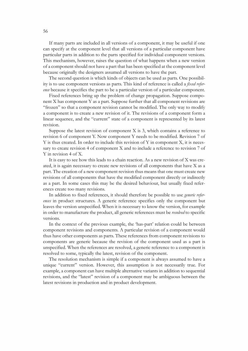
56
If many parts are included in all versions of a component, it may be useful if onecan specify at the component level that all versions of a particular component haveparticular parts in addition to the parts specified for individual component versions.This mechanism, however, raises the question of what happens when a new versionof a component should not have a part that has been specified at the component levelbecause originally the designers assumed all versions to have the part.
The second question is which kinds of objects can be used as parts. One possibil-ity is to use component versions as parts. This kind of reference is called a fixed refer-ence because it specifies the part to be a particular version of a particular component.
Fixed references bring up the problem of change propagation. Suppose compo-nent X has component Y as a part. Suppose further that all component revisions are“frozen” so that a component revision cannot be modified. The only way to modifya component is to create a new revision of it. The revisions of a component form alinear sequence, and the “current” state of a component is represented by its latestrevision.
Suppose the latest revision of component X is 3, which contains a reference torevision 6 of component Y. Now component Y needs to be modified. Revision 7 ofY is thus created. In order to include this revision of Y in component X, it is neces-sary to create revision 4 of component X and to include a reference to revision 7 ofY in revision 4 of X.
It is easy to see how this leads to a chain reaction. As a new revision of X was cre-ated, it is again necessary to create new revisions of all components that have X as apart. The creation of a new component revision thus means that one must create newrevisions of all components that have the modified component directly or indirectlyas a part. In some cases this may be the desired behaviour, but usually fixed refer-ences create too many revisions.
In addition to fixed references, it should therefore be possible to use generic refer-ences in product structures. A generic reference specifies only the component butleaves the version unspecified. When it is necessary to know the version, for examplein order to manufacture the product, all generic references must be resolved to specificversions.
In the context of the previous example, the ‘has-part’ relation could be betweencomponent revisions and components. A particular revision of a component wouldthus have other components as parts. These references from component revisions tocomponents are generic because the revision of the component used as a part isunspecified. When the references are resolved, a generic reference to a component isresolved to some, typically the latest, revision of the component.
The resolution mechanism is simple if a component is always assumed to have aunique “current” version. However, this assumption is not necessarily true. Forexample, a component can have multiple alternative variants in addition to sequentialrevisions, and the “latest” revision of a component may be ambiguous between thelatest revisions in production and in product development.

57
3.5.6.2 Product and Document Versions
A number of documents can be connected to a product. This subsection outlines onepossible arrangement when the products and connected documents have versions.
Suppose a product is connected to some documents. When the product has mul-tiple versions, each version of the product is connected to appropriate versions of theconnected documents. All documents need not be relevant to all versions of theproduct. In this case some version of the product may not be connected to any ver-sion of a particular document although the product as a whole is connected to thedocument.
The creation of a new product version implies a change in at least one documentconnected to the product. Accordingly, new versions are created from one or moredocuments, and these new document versions are connected to the new product ver-sion. As for those documents that were not changed, the new product version is con-nected to the same document versions as the original product version.
On the other hand, a document can be changed without changing the product.For instance, a new version of a user’s guide can be written for an old product version.In this case the connection between a product version and the old version of theuser’s guide is replaced with a connection between the same product version and thenew version of the user’s guide.
The connections between product and document versions as described above arecompletely static in the sense that each product version explicitly defines the docu-ment versions connected to it. One can also speculate with more dynamic connec-tions. Suppose the versioning model distinguishes between major and minorrevisions. A connection between a product version and a document version couldthen specify only the major revision number of the document version. When the sys-tem is asked to find the document versions connected to a particular product version,the system would retrieve the latest minor revision of each connected major revision.In effect, a new minor revision of a document would thus automatically replace theprevious minor revision.
Moreover, a document connected to a product can have multiple variants, forexample in different languages. To find the specific document variants connected toa particular product version, one must also specify a parameter, such as a language,for selecting the correct document variant. The system will then retrieve the latestminor revision of the selected variant of each major document revision connected tothe product.
3.5.7 Larger Versioning Units
Often it is more meaningful to consider a set of related components instead of anindividual component as the unit for versioning. Often the mechanisms for largerversioning units define both a “static” data model, which describes the data stored inthe system, and a “dynamic” operational mode, which describes how the data is
58
manipulated. These mechanisms will therefore be discussed in chapter 4 in connec-tion with design transactions.
3.5.8 Configurable Products and Versions
This section has dealt with versions, which represent the temporal evolution and par-allel alternatives of an object as revisions and variants, respectively. One of the con-cepts was a generic reference, which refers to an object in general and which can beresolved by various means to select a particular version of the object with multiplerevisions and variants.
Section 3.3.2 dealt with configurable products and components. The concept of avariant was fundamental in that section, too. A configurable component correspondsto a set of possible variants, and each configuration of the component represents aparticular variant. It is natural to ask how the configurable products discussed earlierrelate to the revisions and variants of the present section.
In this section the versions of a generic object are supposed to be separate objects.Each version, which represents one revision and variant of a generic object, is anobject of its own. A new variant, or a new version that represents a particular variantand revision, is created explicitly. All variants of an object are thus known and theirnumber is relatively small.
A configurable product also has a number of variants. The set of all variants of aconfigurable product is defined implicitly by an explicit structure and a set of con-straints. Here it is necessary to distinguish between the potential variants of a config-urable product and the variants that have actually been generated for customerorders. A product with many alternative and optional parts can have millions ofpotential variants, of which only a small subset are ever generated.
In general, it is very difficult (and useless) to enumerate all (potential) variants ofa configurable product. Given a configuration model with complex constraints, itmay be difficult to even know if there are any valid configurations of the product atall.
Individual potential variants of a configurable product are not created explicitly.When a configuration model is modified, the corresponding set of variants changes.If the explicit structure of a configuration model is changed, it is usually rather easyto say how the variants are affected. For example, if an optional part is added to aproduct, the number of variants is doubled if constraints are ignored. Nevertheless,if the constraints of a configuration model are changed, it may be very difficult to seethe actual effect of the change.
The section on configurable products ignored the question of revisions. In otherwords, the evolution of configuration models and configurations was not discussed.Unfortunately, not much more can be said within the scope of this thesis. Much morework is needed to include the evolution aspect to the present concepts on configura-ble products. It must be possible to model both the evolution of a configurationmodel as a result of product development and the evolution of individual configura-tions as a result of maintenance and upgrading. There are many interesting, and at the

59
moment unanswered, questions. For example, if a configuration model is modified,is it possible to take a specific configuration based on an earlier revision of the modeland ask how the configuration should be modified to make it complete and valid withrespect to the new revision of the model?

60
4 Design ManagementMany PDM systems support engineering design activities in particular within a com-pany. This chapter briefly deals with those functions of PDM systems that can begrouped under the label Design Management. According to Casotto, Newton andSangiovanni-Vincentelli (1990) the services required from an automatic design man-ager include co-ordination within and between design teams, consistency mainte-nance among data objects, bookkeeping of the design alternatives, policyenforcement, automation of the design flow, documentation of the design process,design estimation, and the verification of design specifications.
This chapter discusses most of the issues of the above list, although not exactlyunder the same headings. For example, the concepts of most subsections can be seenas supporting the co-ordination of team design.
There is a large array of sophisticated concepts for PDM, especially in the contextof design databases (Katz 1990). Nevertheless, it seems that rather few of these con-cepts have actually been in systems that are used in companies, or even if a systemhas an advanced feature, the feature is not necessarily used much.
The gap between theory and practice may be even larger in this chapter than inthe previous one. Although the details vary between PDM systems, there seems tobe some kind of agreement that the data model of a PDM system should include themain concepts discussed in the previous chapter: versions, product structures, linksbetween products and documents, etc. When it comes to the operations that manip-ulate the data, it is more difficult to identify a set of basic concepts that would befound in some form in all PDM systems.
4.1 Design Transactions
A transaction is a fundamental concept in database systems. This concept, however, isnot very useful for PDM systems, which must deal with larger “units of work”. Theterm design transaction (or long transaction) has been coined to refer to the generalidea of a “transaction” that may last for days or weeks as opposed to the seconds ofa traditional transaction and is not based on the “all or nothing” approach of tradi-tional transactions.
This section first briefly describes the properties of traditional transactions. Thisis followed by a discussion on how these properties could be interpreted andextended in PDM systems. The concepts of this section include document versionlife cycles and locking. The term ‘design transaction’ will not be defined in the sameprecise manner in which traditional transactions are defined in database systems. Itmay be a matter of taste whether all issues treated in this section should be includedunder the present heading at all.

61
4.1.1 Traditional Transactions
A transaction is a sequence of database read and update operations that changes adatabase from a consistent state to another consistent state (Korth and Silberschatz1986: sec. 10.2). A classical example is a transaction that transfers money from onebank account to another. The transaction first decreases the amount of money in thefirst account and then increases the amount in the second.
One property of a transaction is atomicity, which means that a transaction is exe-cuted on an “all or nothing” basis. Normally a transaction commits, which means thatthe effects of the update operations within the transaction are permanently recordedin the database. If the transaction cannot be completed for any reason, the transac-tion is aborted and the database is not modified at all. A transaction can be aborted forvarious reasons. For example, the program executing the transaction can explicitlyabort the transaction; the program may be terminated abnormally before the trans-action has committed; or a hardware failure may prevent the database system fromupdating the database. No matter what problems occur in software or hardware, thedatabase system thus guarantees that in the bank account example the database cannever be left in a state where only one of the accounts would be updated.
Another important property of transactions is isolation, which means that theeffects of a transaction are not visible to the other users of the database until thetransaction is committed.
This “traditional” transaction concept is intended for relatively short and simpletransactions, such as the money transfer example, which are executed in large num-bers. In a PDM system, this kind of mechanism is still needed for the database oper-ations at the most basic level, but additional concepts are needed to support typicalproduct data processes, especially in product design (Barghouti and Kaiser 1991).
4.1.2 Transactions in PDM
To illustrate how the concept of a transaction should be extended for PDM, considerthe creation of a new document revision. It is assumed that the new revision is cre-ated in the PDM system immediately when the construction of the revision begins;i.e., not when the finished revision is approved and released for use by everyone. Inthis discussion, the ‘designer’ refers to the person who is responsible for the creationof the new revision.
One basic question is, ‘who sees the new revision and when?’. In traditional trans-actions, the answer is simple: The isolation property means that before the transac-tion has committed, its effects are only seen within the transaction, and after thetransaction hass committed, the effects are seen by all users of the database. How-ever, in a PDM system it is necessary to consider different “levels of commitment”,which determine the set of people who see the effects of the transaction.
A typical process for the creation of a new document revision with related “com-mitments” is outlined below.

62
(1) The transaction is not committed at all. The designer can freely modify the newrevision. The question of whether other users see the new revision is discussedshortly.
(2) The transaction is committed by the designer. The designer has in effect said thatthe new revision is ready as far as he or she is concerned. The revision cannotbe modified, and it must next be checked by someone. As a result, the revisionis either approved or “decommitted” back to step 1.
(3) The revision has been approved. In effect, the transaction is “fully” and irrevo-cably committed. The revision can be seen by all users. If the document needsto be modified, a new revision must be created.
One question is whether other users than the designer can see the new revisionbefore it has been approved. If the answer is positive, the other users must be toldvery clearly that the revision has not been approved. Moreover, the revision itselfshould contain an indication of this fact. For example, if a non-approved documentrevision is printed, one should see from the printout that this revision has not beenapproved.
When discussing the capability of users to see the new revision before its approval,it may be further necessary to distinguish between a user who is only allowed to seethat a new revision exists and a user who is also allowed to see the current contentsof the revision.
This discussion involved two “levels of visibility”: the designer and all other users.There could be additional levels, such as a design team. For example, after a designerhas committed a new revision, the revision could first become visible to the rest of adesign team before the revision is finally approved and made visible to all users. Thistopic is further discussed at the end of the next section.
The atomicity of traditional transactions is also completely infeasible in a PDMenvironment. If the construction of a new document revision were treated as a singletraditional transaction, any problem during this operation, which may last severaldays, could abort the transaction and return the database to the state before the con-struction of the revision was started causing the loss of work already done.
4.2 Check-out/Check-in
Typically the lowest level transactions for the modification of the contents of a doc-ument version are carried out by means of a check-out/check-in mechanism. When auser wants to modify a document version, he or she first checks out the documentversion from the PDM system. Usually this means that the system copies the docu-ment version (more precisely, the document file associated with the document ver-sion) from the PDM database to the user’s workstation. The user then modifies thedocument version in his or her workstation with a suitable tool (see section 5.5.1 on

63
tool integration). Finally the user checks in the document version, i.e., asks the systemto copy the modified document version from the workstation back to the database.
In this section it has been assumed that a single document version can be modifiedrepeatedly with a check-out/check-in cycle during its life cycle. In some systems,however, a check-in operation automatically creates a new document version. In sys-tems that distinguish between major and minor revisions, a check-in operation typi-cally creates a minor revision.
The basic check-out/check-in mechanism has two kinds of “databases” or “work-spaces”: the common shared database, which stores all documents, and the user’s“private” database, to which documents are checked out from the shared database.This two-level model can be extended so that documents are transferred betweenworkspaces, which are arranged in a multilevel hierarchy (Kim et al. 1984).
4.3 Locking
When a user is working on document version, other users must be prevented frommodifying the same version without his or her consent. Users must therefore be ableto lock document versions for their exclusive use with respect to modification.
Suppose revision B is being derived from revision A of a document. If versionbranching is allowed, it is possible to derive another revision B' from revision A.Unless revision B' is going to be a parallel variant of B, revisions B and B' must even-tually be merged to create revision B'', which is the final successor of revision A.
The fact that a user has locked a document revision for himself or herself thusmeans that no one else can unexpectedly interfere with his or her work. Nevertheless,if version branching is allowed and the revision from which the new revision is beingderived has not been “locked” against other derivations, the user cannot be certainthat he or she alone makes the new revision because his or her “version” of the newrevision may have to be merged with other “versions” of the new revision.
The lock and unlock operations can be executed as part of check-out and check-in if the unit to be locked is the same as the unit to be checked out or in. Often, how-ever, there is a set of interdependent objects, and it is necessary to consider the con-sistency of the set of objects as a whole.
A simple example is provided by the EDMS system, which is discussed in the sec-ond part of this thesis. A document version consists of multiple subdocuments, andlock and unlock operations are applied to document versions whereas check-out andcheck-in are applied to individual subdocuments within a locked document version.
The model presented by Cellary, Vossen and Jomier (1994) groups objects intosets called constellations. The objects in a constellation form a meaningful whole fromthe designers’ point of view, and for each constellation there is a designer responsiblefor the constellation. An object can belong to multiple constellations, and the rela-tionships between constellations correspond to the relationships between designerswho are responsible for the constellations. For example, if constellation Y is nestedwithin constellation X (i.e., all objects that belong Y also belong to X), the designer

64
responsible for constellation X as a whole can be seen as having delegated theresponsibility for constellation Y within X to a subordinate designer. The division ofobjects among constellations thus reflects the division of design tasks among design-ers.
4.4 States
The different “levels of commitment” for a document version that were discussed insection 4.1.2 can be described by means of states. One can also say that the states rep-resent different milestones during the life cycle of a document version or other objectthat begins with the creation of a new object and guides the object through variouschecking, approval and release procedures.
The states are often called release levels or promote levels (Miller, MacKrell and Mendel1997: 14). Although this term may imply that the states are arranged in a linearsequence, in general the states can form more complex graphs with branching andmerging.
Usually the current state of an object partly determines the set of operations thatcan be applied to the object. For example, the contents of a document version shouldobviously not be modified if it is in the state ‘waiting to be approved’ or ‘approved’.
4.5 Dependencies
The objects in a PDM database have dependencies between them. Object Y is said todepend on object X if the modification of X may make it necessary to modify Y, too.In some cases it may be possible to define automatic regeneration rules for a depend-ent object so that whenever object X is modified, the system automatically regener-ates Y by executing a suitable program. In most cases, however, after themodification of X, the system can only mark Y as ‘invalid’, or more precisely ‘poten-tially invalid’. A user must then check whether Y needs to be modified and carry outthe modifications if necessary.
Suppose further that object Z depends on object Y, which in turn depends onobject X. When object X is modified, object Y must be checked and possibly modi-fied. It is not immediately necessary to do anything with object Z. Nevertheless,object Z is still in the scope of “potential changes” because it must be checked, andpossibly modified, in case Y is modified as a result of the modification of X.
Dependencies were described here as being recorded between documents. Inpractice this is a rather coarse unit of dependency. For example, consider a specifica-tion document and any of the many drawings of a product. There is a dependencybetween the documents: if the specification is modified, it may be necessary to mod-ify the drawing. Nevertheless, to be useful, the dependency should probably be muchmore detailed. For example, it should be possible to record a dependency between aparticular item in the specification and a particular part in a particular drawing. Obvi-

65
ously the recording and maintenance of dependencies at a useful level requires a con-siderable amount of work, and the whole concept may be infeasible in practice.
4.6 Workflows
Designers need a wide array of tools for their work. Often the tools must be used ina particular order because the output from one tool serves as input to another tool.A tool can require multiple input files and generate multiple output files, creatingcomplex dependencies between files and the tasks in which the tools are executed.After a set of data has been processed with a tool, the next step in a process maydepend on the outcome of the execution of the tool.
In addition to multiple tools, a data object, such as a document, may have to bemanipulated by multiple people in a predetermined manner. For example, an organ-isation can define that a document revision cannot be approved unless it is acceptedby all members of a group. As another example, the processing of an engineeringchange order can involve several steps during which various documents are sent forapproval and processing to different people.
For example, the model by Allen, Rosenthal and Fiduk (1991) is based on processtools The description of a tool specifies input and output files, a command line toexecute the tool, pre-conditions, which must be met before the tool can be executed,and post-conditions, which determine whether the tool was executed successfully.
Especially in a one-of-a-kind-industry, such as ship building or process plant con-struction, it seems necessary to have digital means of communication that are lessformal than workflow procedures. Many companies that work on large projects havecomplemented centralised PDM systems with groupware products, such as LotusNotes (Hameri and Nihtilä 1998).
4.7 Documentation of the Design Process
After the completion of a design task it is obviously important to know the designresults. However, often it is also useful to know how the results were reached. Forexample, when the design of a complex product must be modified, it is useful toknow why particular decisions were made, what alternatives were considered, andwhy they were rejected.
This kind of supplementary information is often called design rationale. Designerscan record design rationale during the design process or the designers can recon-struct the design rationale afterwards by reasoning from their existing knowledge,conducting interviews and examining the finished design and unstructured recordsfrom the design process, such as video tapes from meetings (Lee 1997).
Information on ‘why’ is difficult to capture in a design process because it can onlybe provided by the designers. Information on ‘what’, ‘when’ and ‘by whom’, however,is automatically available in a PDM system. If necessary, a PDM system can create alog file, which records for each database update what data was modified, when and

66
by whom. Obviously the automatically collected information on modifications isoften rather coarse. For example, if a designer modifies a drawing, a PDM system (orCAD system) cannot typically provide much information about what was actuallymodified within the drawing.
It may be possible to compute useful statistics from the automatically collecteddata. For example, a suitable log file allows managers to see how much time typicallyelapses from the moment a designer submits a modified document for approval untilthe moment the document is approved or rejected.
Usually a log file only records information about data modifications. Nevertheless,for security reasons a company may want the PDM system to also record informationabout users who have retrieved data from the system.

67
5 System Aspects
5.1 System Architecture
A PDM system must be built on top of a database management system that stores atleast most of the data handled by the PDM system. This database is usually a rela-tional database system. Of the 52 PDM systems reviewed in a leading survey, 43 sys-tems used a relational database, 2 systems used a commercial object-orienteddatabase, 2 systems used their own “object-oriented” database, and the remaining 5system used some other database (Miller, MacKrell and Mendel 1997: 99). AlthoughPDM systems have been mentioned as a good application for object-oriented data-bases (Cattell 1994), object-oriented databases obviously have made very little impacton the commercial PDM field.
When discussing the possible “object-orientedness” of a PDM system it is impor-tant to distinguish between the properties of the tool that is used for implementingthe system and the properties that the system provides for its users. The fact that asystem is written in an object-oriented programming language does not necessarilymean that there would be much “object-orientedness” in the concepts seen by theuser, such as inheritance between document types. On the other hand, it is also pos-sible to implement object-oriented concepts with a conventional relational database(Barsalou and Wiederhold 1990).
Most PDM systems are based on a client-server architecture, in which the usersexecute a client program on their workstations, and the clients communicate with aserver program, which in turn accesses the database. The system described in detailin the second part of the thesis is an example of this architecture.
Web technology is important for PDM systems because it allows users to accessthe system from standard Web browsers. Some systems make all functions of the sys-tem available through a Web browser; in other systems only the most common oper-ations can be carried out through the Web while the remaining operations require thespecific PDM tool. The system described in the second part of the thesis is an exam-ple of the latter approach.
When a company wants to start using a PDM system, almost all systems requireat least some company-specific customisation. For example, usually a company wantsto define its own document types and attributes. PDM systems differ widely in theamount of customisation that can and must be done. At one extreme there are sys-tems with minimal, if any, needs, and possibilities, for customisation. It is easy for acompany to start using this kind of system as long as the predefined properties satisfythe requirements of the company. At the other extreme there are PDM toolkit sys-tems, which only provide a set of building blocks for constructing a working system.Although toolkits make it possible to build a system to the exact requirements of acompany, the necessary customisation and programming raises the costs considera-bly. Some vendors of PDM toolkits have found it necessary to also sell “ready-made”

68
systems, which reduce the need for customisation at the expense of flexibility (CAD/CAM 1998).
5.2 Metamodels and Company Models in Relational Databases
Section 3.1 introduced the concepts of a metamodel and a company model. This sec-tion describes two alternative ways to implement the models on top of a relationaldatabase.
A relational database has a schema, which defines a set of tables and a set of col-umns for each table. The data are stored as rows of the tables, with each row havinga value (possibly a null value) for each column of the table. To some extent, the rela-tional model can be described in object-oriented terms. The tables and their columnsrepresent object types and their attributes, respectively. The rows in a particular tablerepresent instances of the corresponding type.5
When a PDM system has three levels of entities as explained at the end of section3.1, it is not obvious how the system should be implemented on a relational databasewith two levels.
As a concrete example, suppose a PDM system contains the object types ‘drawing’and ‘manual’, drawings ‘d1’ and ‘d2’, and manual ‘m1’. One way to represent this datain a relational database is to have one table for object types and another table forobject instances. The latter table includes columns for object name and type. Thisalternative is illustrated in figure 11.
Next, one must consider that different object types have different attributes. Forexample, suppose that the object type ‘drawing’ has the attribute ‘drawing_size’,which stores a string (e.g., ‘A3’), and the object type ‘manual’ has the attribute‘page_count’, which stores an integer. One possibility is to store information aboutattributes in one table and the attribute values in another table. The attribute tables,which are used together with the tables of figure 11, are illustrated in figure 12. The
5. Although the relational model does not include the concept of an object, a row of a table can beinterpreted as an object if the table has a column that stores unique object identifiers.
Figure 11. Two tables for types and instances
table ‘object_types’
object_type
drawing
manual
table ‘objects’
name type
d1 drawing
d2 drawing
m1 manual

69
type of the column ‘attribute_value’ in the table ‘attribute_values’ must be ‘string’ sothat the column can store any attribute value that can be represented as a string.
In practice separate tables are needed for different attribute value types. Althoughnumeric values can be stored as strings, strings are compared according to the alpha-betical order, which gives the wrong result for numeric values.
This representation of objects and their attributes is called here the ‘fixed databaseschema’ approach because the database schema, i.e., the set of tables and their col-umns, does not depend on the object types and attributes in the company model.
This representation, however, is not the only possibility. The representationresulted from two assumptions: (1) the object types and their attributes must be rep-resented dynamically as data, and (2) the relational database must have a fixedschema. If the first assumption is removed and one is simply asked to design a data-base that can store drawings and manuals with the given attributes, one probably cre-ates separate tables for drawings and manuals as shown in figure 13.
Figure 12. Two tables for attributes and their values
Figure 13. Separate tables for different object types
table ‘attributes’
object_type attribute_name attribute_type
drawing drawing_size string
manual page_count integer
table ‘attribute_values’
object_name attribute_name attribute_value
d1 drawing_size A4
d2 drawing_size A3
m1 page_count 26
table ‘drawings’
drawing_name drawing_size
d1 A4
d2 A3
table ‘manuals’
manual_name page_count
m1 26

70
Although figure 13 may be a natural representation for a fixed set of object typesand attributes, a PDM system must have dynamic schema and provide operations forcreating new object types and adding attributes to existing types. The tables‘object_types’ and ‘attributes’ of figures 11 and 12 are thus needed. Nevertheless, aPDM system can still store objects and attributes in separate tables in the style of fig-ure 13 because a PDM system is not limited to the data manipulation operations ofa relational database (e.g., ‘insert a row into a table’). A PDM system can equally wellexecute data definition operations, such as ‘create a table’ or ‘add a column to a table’.
This approach, called here the ‘dynamic database schema’, is illustrated in figure14. There are two kinds of tables in a particular database. The fixed metamodel is rep-resented by the tables ‘object_types’, ‘attributes’ and ‘objects’, which exist in everydatabase. The varying object types of a company model are represented by the rowsof the fixed tables and by the tables ‘objects_XXX’. The instances of the object type‘XXX’ are represented by the rows of the tables ‘objects_XXX’. The dual nature ofa particular object type both as an instance with respect to the metamodel and as atype with respect to the company model is obvious when one considers the creationof a new document type. This operation inserts rows into tables ‘object_types’ and‘attributes’, and creates a new table ‘objects_XXX’.
Figure 14. Dynamic schema and type-specific tables
table ‘attributes’
object_type attribute_name attribute_type
drawing drawing_size string
manual page_count integer
table ‘object_types’
object_type
drawing
manual
table ‘objects’
name type
d1 drawing
d2 drawing
m1 manual
table ‘objects_drawing’
object_name drawing_size
d1 A4
d2 A3
table ‘object_manual’
object_name page_count
m1 26
fixed schema
company-specific schema

71
If objects are represented with a dynamic database schema, many of the SQLstatements that manipulate the database must be generated at run-time. For example,consider a query to find objects of a particular type with a particular value for a par-ticular attribute. The names of the table and the column cannot be written directly inprogram code. Instead, the table and column names must be formed at run-timefrom the names of the object type and attribute.
Note that the difference between a fixed and a dynamic database schema onlydeals with the representation of the company model in a relational database. Bothapproaches support dynamic company models, in which, for example, new objecttypes and attributes can be added to an existing database.
The main advantage of the fixed database schema is that it scales well to an arbi-trary large number of object types and attributes. When new object types andattributes are added to the company model, only new rows are added to the fixedtables. In a dynamic database schema, new tables and columns are added. This is nota problem when there are relatively few—a few dozen—object types. Nevertheless,there can be far more object types if, for example, different component types in acomponent class hierarchy (section 6.2) are represented as object types. In this casethe large number of tables may become a problem.
In a dynamic database schema each attribute is stored in its own column. Theproperties of a particular column can thus be specified for the correspondingattribute. For example, each string attribute can have its own maximum length, andthe corresponding column in a database table can have the same width. It is also pos-sible to create indices for individual attributes.
Queries are simpler with a fixed database schema in the sense that the names oftables and columns do not have to be created dynamically. On the other hand, thequeries are shorter with a dynamic database schema. For example, figure 15 shows aquery that finds all objects of the type ‘manual’ with particular values for theattributes ‘page_count’ and ‘create_time’.
The difference in queries is probably not much of an issue when the queries aregenerated by the PDM system. When a system administrator has to execute ad-hocqueries, a dynamic database schema is probably more convenient.
With a dynamic database schema, a query over multiple object types is executedas separate queries to the tables that store objects of different types. Again, this solu-tion works for a relatively small number of object types but is probably infeasiblewhen the number of object types grows.
The system described in the second part of the thesis uses a dynamic databaseschema because the system is developed for a fairly small number of object types.The details are given in section 11.9. This approach works fine in the kind of envi-ronment to which the system was built (about ten object types). Nevertheless, asexplained above, there may be problems with a larger number of object types.
Usually a database application has a fixed schema, which can, for example, be rep-resented as a single UML class diagram. A PDM system is more complicated in thisrespect because two kinds of diagrams are needed. One diagram describes the meta-
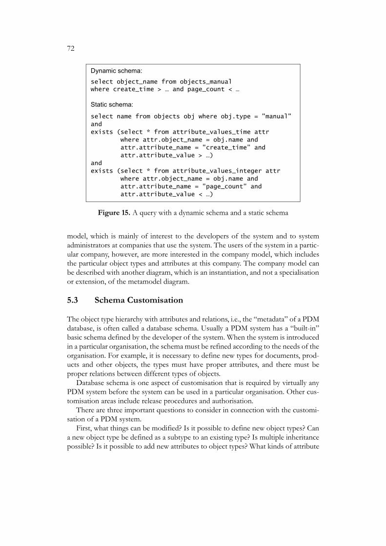
72
model, which is mainly of interest to the developers of the system and to systemadministrators at companies that use the system. The users of the system in a partic-ular company, however, are more interested in the company model, which includesthe particular object types and attributes at this company. The company model canbe described with another diagram, which is an instantiation, and not a specialisationor extension, of the metamodel diagram.
5.3 Schema Customisation
The object type hierarchy with attributes and relations, i.e., the “metadata” of a PDMdatabase, is often called a database schema. Usually a PDM system has a “built-in”basic schema defined by the developer of the system. When the system is introducedin a particular organisation, the schema must be refined according to the needs of theorganisation. For example, it is necessary to define new types for documents, prod-ucts and other objects, the types must have proper attributes, and there must beproper relations between different types of objects.
Database schema is one aspect of customisation that is required by virtually anyPDM system before the system can be used in a particular organisation. Other cus-tomisation areas include release procedures and authorisation.
There are three important questions to consider in connection with the customi-sation of a PDM system.
First, what things can be modified? Is it possible to define new object types? Cana new object type be defined as a subtype to an existing type? Is multiple inheritancepossible? Is it possible to add new attributes to object types? What kinds of attribute
Figure 15. A query with a dynamic schema and a static schema
Dynamic schema:
select object_name from objects_manualwhere create_time > … and page_count < …
Static schema:
select name from objects obj where obj.type = "manual"
and
exists (select * from attribute_values_time attr
where attr.object_name = obj.name and
attr.attribute_name = "create_time” and
attr.attribute_value > …)
and
exists (select * from attribute_values_integer attr
where attr.object_name = obj.name and
attr.attribute_name = "page_count" and
attr.attribute_value < …)

73
value types are available? Is it possible to customise document release procedures?For example, if release procedures are based on state graphs, can completely newgraphs be defined and can new states and state transitions be added to existinggraphs?
Second, who can modify the system? Can the modifications mentioned above bemade by the system administrator at a user organisation, or is it necessary to orderthe modifications from the system vendor? In the latter case the costs are often quitehigh.
Third, when can the system be modified? Must the object types and theirattributes be fixed before the database is created? Is it possible, or easy, to add a newobject type to an existing database or to add a new attribute to an existing object type?
The desired answers to the above questions are obvious. A PDM system shouldallow the system administrator to define object types and their attributes. It shouldalso be possible to add attributes to an object type, remove attributes, and changeattribute value types (e.g., to increase the maximum length of a character stringattribute).
It is clear that the attributes cannot be changed lightly in a large database evenwhen the operation is technically simple. If a new attribute is added to an object type,all existing objects have a null value for this attribute. The attributes needed for var-ious objects in a PDM system must be considered carefully when a company plansthe introduction of a PDM system. An attribute is useless unless the users are pre-pared to enter a value for the attribute when they create objects and maintain thevalue afterwards if necessary.
5.4 Access Control
A PDM system must have a mechanism for controlling who can read and modifydata in the system. There are many more operations than simply ‘read’ and ‘modify’that must be controlled. For example, it may be necessary to distinguish betweenreading the actual contents of a document and reading the attribute values of a doc-ument. Similarly, a document or other object can be modified in many ways: one canmodify attribute values, modify document contents, create a new version, change thestate of an object, etc. Attributes may be controlled in more detail so that particularusers can read and modify particular attributes.
Usually access rights are not granted directly to individual users. Instead, the rightto perform a particular operation is granted to a named user group, and each user canbe a member of one or more user groups. The set of users who have rights to anobject may depend on the properties of the object. For example, a document canhave an attribute for the name of the department that the document belongs to, andeach department can be associated with the names of users who can approve the doc-uments of that department.

74
The operations that can be applied to an object can also depend on the propertiesof the object, such as its current state. For example, it is usually forbidden to modifyan approved document.
Section 11.4 in the second part of the thesis contains one example of a powerfulaccess control mechanism.
5.5 Integration between PDM and Other Systems
The usability of a PDM system greatly depends on how well the PDM system workstogether with other systems that must exchange data with it. This section briefly dis-cusses the integration of PDM with document tools and ERP systems.
5.5.1 PDM and Document Tools
Usually the user of a PDM system does his or her “real work” with a document tool,which manipulates the document files associated with documents or document ver-sions. It is convenient if at least the most common PDM operations, such as check-out and check-in, can be carried out directly within the document tool. This way theuser does not have to switch between the document tool and the PDM system; infact, some users may never use the PDM system as a separate tool.
What is needed is thus an interface between a document tool and the documentmanagement functions of a PDM system. One way to avoid developing this interfaceseparately for all combinations of document tools and PDM systems is the OpenDocument Management API (ODMA) standard (AIIM 1997).
Basically ODMA defines an interface that allows the ‘open’ and ‘save’ operationsof a document tool to retrieve a document file from a PDM system and store a mod-ified document file back to the PDM system. When an “ODMA enabled” documenttool executes an ‘open’ operation, the tool first checks if it has an ODMA connectionto a PDM system. If a connection is present, the tool issues a ‘select’ command tothe PDM system, which asks the user to select a document (or document version orsomething similar) from its database. Instead of selecting a document from the PDMsystem, the user can also cancel the whole operation or say that he or she wants toselect a file using the regular file selection facilities of the document tool.
If, however, the user has selected a document from the PDM system, the ‘select’operation returns a document identifier to the document tool, which issues an ‘open’command with the document identifier as a parameter. In response to ‘open’, thePDM system executes check-out and copies the document file associated with thedocument to a temporary file that can be accessed by the document tool and returnsthe name of the file to the document tool. The tool then opens the temporary file inthe normal way.
When document tool executes ‘save’ on a document retrieved from the PDM sys-tem, it writes the document to the temporary file and issues a ‘save’ command to thePDM system, which copies the contents of the temporary file to the PDM system.

75
After a ‘save’ operation the PDM system returns a new document identifier becausethe identifier may have changed, for example, because the PDM system has createda new document version.
In addition to ‘select’, ‘open’ and ‘save’, ODMA defines typical additional docu-ment management operations, such as ‘cancel check-out’, ‘create major version’, ‘cre-ate minor version’ and ‘show document history’. The PDM system does not have toinclude all additional functions because ODMA allows the document tool to checkwhich operations are supported by the PDM system it is connected to.
ODMA also defines a number of document attributes, such as the name of theuser who has checked out the document, the time of the check-out operation, thename of the latest version of the document, etc. A document tool can again checkwhich attributes are supported by the PDM system and then read and write the avail-able attributes of a document.
5.5.2 PDM and ERP Systems
If a company has both a PDM system and an ERP system, data must be sharedbetween the two systems. For example, consider the parts list of a product. This datais needed in both systems, and possibly in further other systems, such as CAD tools.To keep the data consistent, it is necessary to define the system, or systems, that storethe modifiable “master copy” of the data, and how the modified data is transferredto other systems that use the data. The integration between systems is often furthercomplicated by the fact that product data is divided between the systems so that nosingle system stores all data needed by other systems. For example, a new productmay first be created in a PDM system, which supports product development. Part ofthe product data is transferred from the PDM system to an ERP system, which addsits own data. As a result, data about a single product is stored in two systems, andsome data must be maintained consistent between the systems. It may also be neces-sary to transfer some of the data managed by the ERP system back to the PDM sys-tem.
Data exchange and sharing between PDM and ERP becomes even more complexif a product has multiple product structures. In this case some structures, such as an‘as-designed’ structure, may be manipulated in a PDM system while other structures,such as an ‘as-built’ structure, are manipulated in an ERP system (IPDMUG 1995).
A survey by Hameri and Nihtilä (1998) found that many companies were pilotingintegration between PDM systems and ERP systems. Although integration was inmost cases technically feasible, there were often organisational problems relating tothe question of whether the integration should be based on PDM or ERP.

76
6 PDM Standards
6.1 STEP Standard
As should become obvious from this thesis, PDM systems use a large number of con-cepts that are more or less related but for which there are no universally acceptedstandards. For example, practically all PDM systems have some notion of versions,but there is no agreement on the meaning of the terms ‘version’, ‘revision’, ‘variant’,etc.
One standardisation effort is the international standard for the Exchange of prod-uct Data, officially known as ISO 10303 and generally referred to as the STEP stand-ard (Owen 1997). The scope of the standard is very large because the goal is todevelop a standard for the representation of all data related to products.
The first parts of the standard were accepted in 1994, and new parts are continu-ously being developed and accepted as standards. In spite of the many years of hardwork to develop STEP, the effect of STEP on the PDM field is still rather marginal.Time will tell whether STEP ever meets the high expectations in wider industrial use.
This section very briefly outlines the structure of the STEP standard and in par-ticular the representation of product structures. STEP has a number of parts; in 1997there were 14 approved parts and over 40 additional parts under development. Theparts are divided into several classes, the most important of which are described here.
A very large portion of STEP deals with the representation of geometric data. Atthe moment this is probably the most successful part of STEP. The brief discussionin this thesis, however, mainly deals with the mechanisms that STEP provides forproduct structures. If STEP is to serve as a universal basis for product modellingtools of the future, it must clearly support generic product structures. Nevertheless,section 6.1.5 explains why it is presently difficult to incorporate generic productstructures in the general STEP framework.
6.1.1 Express Language
STEP defines a number of data models for various aspects of product data. All datamodels are defined by means of a schema definition language called EXPRESS (ISO1994a). EXPRESS can be regarded as a semantic database modelling language (Hulland King 1987). This means that EXPRESS can be used for defining a databaseschema that consists of object types, their attributes, relations between objects andvalidity constraints. These concepts will be discussed in slightly more detail shortly.
It is important to understand that EXPRESS only describes the structure of data,not any behaviour. Given a population of objects (i.e., a database instance) and anEXPRESS schema, one can say whether the object population is valid with respectto the schema. EXPRESS is not a programming language and does not include anymechanism for defining operations or methods for the objects described in theschema. A superficial glance at EXPRESS may be misleading in this respect because

77
the language includes procedures and functions, which can contain familiar program-ming constructions, such as variables, conditional statements and loop statements.Nevertheless, these constructions can only be used in validity constraints and defini-tions of derived attributes. A validity constraint can thus be an arbitrarily complexalgorithm written in a “programming language” but all the same the algorithm onlydefines a test for determining whether an object or a population of objects is valid.
6.1.1.1 Entities and Classification
An EXPRESS schema basically defines a number of object classes, called entities inEXPRESS. An entity declaration can specify attributes, uniqueness rules and domainrules (rules will be discussed later).
In section 3.2.1 the word ‘entity’ was suggested as a substitute for the word‘object’. In EXPRESS, however, the word ‘entity’ corresponds to an object type oran object class, and an individual object is an entity instance (i.e., an instance of anentity).
Compared to the classification mechanisms of section 3.2.1.2, EXPRESS hasexceptionally powerful concepts for building class hierarchies. An entity declarationcan specify one or more entities as the immediate supertypes of the new entity.EXPRESS thus allows multiple inheritance. What distinguishes EXPRESS frommost object-oriented programming languages is the possibility to specify whethersubtypes of an entity are mutually exclusive or mutually inclusive. Consider firstmutually exclusive subtypes. Suppose that the entity ‘computer’ should be an abstracttype with the subtypes ‘portable computer’ and ‘desktop computer’. Each computeris thus either a laptop computer or a desktop computer. In EXPRESS this would bewritten as follows (reserved EXPRESS words are conventionally written in upper-case letters):
ENTITY computer
ABSTRACT SUPERTYPE OF (ONEOF(portable_computer,
desktop_computer));
…
END_ENTITY;
ENTITY portable_computer
SUBTYPE OF (computer);
…
END_ENTITY;
ENTITY desktop_computer
SUBTYPE OF (computer);
…
END_ENTITY;

78
The ‘ONEOF(…)’ subtype constraint thus specifies that a ‘computer’ entity is alwaysexactly one of the listed entities. As ‘computer’ is abstract, no entity can be “just acomputer”.
Exclusive ‘ONEOF’ subtypes are the familiar case, which is usually the only alter-native in object-oriented systems. EXPRESS, however, makes it possible to specifymutually inclusive subtypes. For example, suppose all computers are represented withthe concrete entity type ‘computer’, and portable computers are a special case ofcomputers represented with their own subtype. Moreover, a PC is another specialcase of a computer. Now, the two subtypes of computer are mutually inclusivebecause a computer can be a portable PC. These entities would be modelled as fol-lows:
ENTITY computer
SUPERTYPE OF (portable_computer ANDOR PC);
…
END_ENTITY;
ENTITY portable_computer
SUBTYPE OF (computer);
…
END_ENTITY;
ENTITY PC
SUBTYPE OF (computer);
…
END_ENTITY;
As a third example, suppose a computer is either a portable computer or desktopcomputer, and at the same time either a home computer or a business computer. Thisclassification according to two orthogonal dimensions would be represented as fol-lows:
ENTITY computer
SUPERTYPE OF (ONEOF(portable_computer, desktop_computer)
AND
ONEOF(home_computer, business_computer));
…
END_ENTITY;
6.1.1.2 Attributes
An attribute declaration within an entity declaration specifies the name and (value)type of the attribute. The possible attribute types include integer numbers, floatingpoint numbers, strings, logical values (true, false and unknown) and references toentities. An attribute type can also be a list, set or bag (set with multiple identical val-

79
ues) of values. An attribute can be declared optional, which means that an instanceof the entity does not have to have a value for the attribute.
The declaration of a derived attribute includes an expression that tells how thevalue of the attribute is computed from the values of other attributes.
An attribute can be declared to record a reference to an entity of a particular type.If an entity refers to another entity through an attribute, the second entity can declarean inverse attribute, which refers back to the first entity. In the following example theentity ‘person’ has the attribute ‘hometown’, which refers to an entity ‘town’. Theentity ‘town’ in turn declares an inverse attribute ‘citizens’, which records the peopleof the town.
ENTITY person;
hometown : town;
…
END_ENTITY;
ENTITY town;
citizens : SET OF person FOR hometown;
…
END_ENTITY;
The cardinality of a relation established with reference attributes is specified throughthe cardinalities of the attributes that create the relation. In the previous example,each person is related to exactly one town, and each town is related to any numberof people. If, for example, each town must have at least one citizen, the correspond-ing attribute should be declared as follows:
INVERSE
citizens : SET [1..?] OF person FOR hometown;
Entities inherit attributes in the usual way from their supertypes. An entity can alsoredeclare an inherited attribute. The new type of a redeclared attribute must be a spe-cialisation (subtype) of the original attribute type. For example, if the entity ‘cus-tomer’ declares an attribute of the type ‘computer’, then a subtype of ‘customer’, suchas the entity ‘business customer’, can redeclare the type of the attribute to be a sub-type of ‘computer’, such as ‘business computer’. Redeclaration of a referenceattribute thus corresponds to the part refinement discussed in section 3.3.2.8.
6.1.1.3 Relations
As seen in the previous example, EXPRESS basically represents a relation betweenentities with reference attributes, optionally supplemented with inverse attributes torecord the references “in the other direction”. As discussed in section 3.2.3, the rep-resentation of relations as attributes means that relations are not “first-class citizens”and cannot, for example, have attributes. Therefore many parts of STEP represent

80
relations by means of “relationship entities” that contain references to the actual enti-ties that participate in a particular relation.
For example, consider the relation between people and towns in the previousexample. The fact that a particular person lives in a particular town could also be rep-resented with an entity ‘residence’ that has attributes referring to the related personand town. The ‘residence’ entity can now define additional attributes and it is possibleto declare new entities as subtypes to this entity.
ENTITY residence;
citizen : person;
hometown : town;
…
END_ENTITY;
6.1.1.4 Constraints
An entity can specify domain rules, which are conditions that must be satisfied byevery individual instance of the entity. A domain rule is a logical expression, whichcan refer to the attributes of the entity and which always yields the value ‘true’ or‘unknown’ in an instance of the entity. The value of the logical expression can be‘unknown’ if the expression refers to an optional attribute that has no value in theinstance.
Whereas a domain rule is a condition for individual instances of an entity, unique-ness constraints and global rules are conditions for an object population as a whole.
An entity declaration can include uniqueness constraints, which specify that allinstances of the entity must have different values for a particular attribute or attributecombination (within a particular object population). For example, the entity ‘compo-nent’ with attribute ‘id’ could specify that all instances of the entity must have a dif-ferent value for this attribute, and the entity ‘component version’ with attributes‘component id’ and ‘version id’ could specify that the combination of the values ofthe two values must be unique in the instances of the entity in an object population.
Domain rules and uniqueness constraints declared in an entity are inherited by thesubtypes of the entity. An instance of an entity thus also satisfies all domain rules anduniqueness constraints of its supertypes.
An EXPRESS schema can include global rules, which, unlike domain rules anduniqueness constraints, are not defined within a particular entity declaration. A globalrule can make queries on the object population and, for example, say that there is atleast one instance of a particular entity that satisfies a particular condition. A globalrule can use all the “programming language” constructs of EXPRESS, and it is there-fore possible to write any kind of algorithmic rule.
Consider the following EXPRESS entity, which defines an integer attribute and adomain rule that says that the value of the attribute is positive.
ENTITY E;
i : INTEGER;

81
WHERE
i > 0;
END_ENTITY;
It seems natural to imagine an object population that contains an instance of entity‘E’ where the value of the attribute ‘i’ is negative and to say that this is an invalidinstance of entity ‘E’. Nevertheless, strictly speaking EXPRESS has no notion of aninvalid instance of an entity. As EXPRESS is a data modelling language, a schemaonly describes what kind of objects can be found in an object population. In princi-ple, it is as meaningless to talk about an instance of ‘E’ with a negative value ofattribute ‘i’ as it is meaningless to talk about an instance of ‘E’ in which the value of‘i’ is a string instead of an integer or which has value for some attribute ‘x’ instead ofattribute ‘i’.
The fact that EXPRESS does not recognise “different kinds of invalidity” is nat-ural when one considers the original goal of EXPRESS and STEP in general.EXPRESS is a tool for describing product data that is exchanged between computersystems. It does not make sense to specify how a system should behave if it receivesdata that does not fully conform to the schema that it is supposed to conform to.Nevertheless, as will be seen later in this section, this property of EXPRESS causesproblems if one tries to use EXPRESS outside its original domain of data exchange.
6.1.1.5 EXPRESS-G
EXPRESS-G is a graphical notation for schemas defined in EXPRESS. AnEXPRESS-G diagram can only show entities and their attributes (including refer-ences to other entities) but not any rules. An EXPRESS-G diagram thus gives anincomplete but comprehensible overview of a schema, which must be described indetail with the textual EXPRESS language.
6.1.2 External Representation of EXPRESS Data
The original goal of STEP is to make it possible to exchange product data betweenorganisations. STEP Part 21, called ‘Clear text encoding of the exchange structure’therefore specifies how a set of instances of entities defined in an EXPRESS schemaare represented as a textual physical file (ISO 1994c).
As a very simple example, consider the following schema:
SCHEMA residences;
ENTITY person;
name : STRING;
hometown : town;
END_ENTITY;
ENTITY town;
name : STRING;

82
country : STRING;
INVERSE
citizens : SET OF person FOR hometown;
END_ENTITY;
A physical file with a couple instances of these entities could look as follows:
ISO-10303-21;
HEADER;
FILE_DESCRIPTION(…);
FILE_NAME(…);
FILE_SCHEMA(('residences'));
ENDSEC;
DATA;
#1 = TOWN('Helsinki', 'Finland');
#2 = TOWN('Washington, D.C.', 'USA');
#3 = PERSON('Hannu', #1);
#4 = PERSON('Bill', #2);
ENDSEC;
END-ISO-10303-21;
Inverse (and derived) attributes do not appear in the physical file because their valuesare automatically determined from the values of the explicit attributes.
In addition to a text file, EXPRESS data can be stored in a repository, which can,for example, be implemented as a file or a database. The contents of a repository areaccessed by means of operations defined as a Standard Data Access Interface (SDAI)in STEP Part 22. The SDAI is thus an Application Programmers’ Interface (API) toan EXPRESS repository.
Part 22 is independent of any programming language. Further parts define lan-guage bindings, which tell how the operations of the SDAI are used from an applica-tion written in different programming languages such as C, C++ and Java.
6.1.3 Integrated Resources
The next subsection explains how the STEP standard ultimately defines a number ofapplication protocols for exchanging product data between applications. Many appli-cation protocols must represent similar data. For example, almost all application pro-tocols include some kind of geometric data.
The application protocols are built from integrated resources, which are dividedinto generic integrated resources and application integrated resources. As the namessuggest, the former ones are intended for all kinds of applications while the latterhave been developed for a range of similar applications.
The rest of this subsection briefly describes the generic integrated resources ofParts 41 and 44, which are the main resources for product structures.

83
6.1.3.1 STEP Part 41
STEP Part 41 is called ‘fundamentals of product description and support’ (ISO1994d). Among other things, this part defines an application context in which prod-uct data can be defined. Each application context is associated with one or moreapplication context elements, which can define the following aspects of the applica-tion context:
• Product context, which defines a discipline type, such as ‘electrical’ or ‘mechani-cal’.
• Product definition context, which defines a life cycle stage, such as ‘as designed’or ‘as specified’.
• Product concept context, which defines a market segment type, such as ‘luxuryautomobiles’.
• Library context, which defines a library reference, such as ‘the products of com-pany XYZ’.
STEP defines that “a product is the identification and description, in an applicationcontext, of a physically realisable object that is produced by a process” (ISO 1994d:13). A product is associated with one or more product contexts within which theproduct is defined.
A product is described by means of product definitions, each of which is associ-ated with a single product definition context (i.e., a life cycle stage). A product, how-ever, is not directly related to product definitions. Instead, a product is associatedwith a set of product definition formations, which can for example represent differ-ent versions of the product, and each product definition formation is associated witha set of product definitions.
A product definition can be associated with properties, such as shape, which arefurther associated with property representations, such as a particular kind of geomet-ric representation of a shape property. A product definition can also be associatedwith documents.
It is necessary to establish various relationships between product definitions, oneobvious example being the ‘has-part’ relationship for a hierarchical product break-down structure. Part 41 only defines a product definition relationship, which is anentity for representing any relationship between two product definitions. Since therelationship has no particular meaning at this level, the two product definitions aresimply designated as ‘relating product definition’ and ‘related product definition’. Thenext subsection shows an example of how other integrated resources and applicationprotocols define subtypes of the relation entity for more specific relationshipsbetween product definitions.

84
6.1.3.2 STEP Part 44
STEP Part 44 is called ‘product structure configuration’ and defines a mechanism forthe presentation of hierarchical product breakdown structures (ISO 1994e). Sincethis part is a generic integrated resource, the mechanism is used in all parts of STEP.
As mentioned earlier, Part 41 defines the entity ‘product definition relationship’to represent a relationship between a ‘relating’ and a ‘related’ product definition. Part44 defines the entity ‘product definition usage’ as a subtype of this entity. The entity‘product definition usage’ has further two subtypes.
The entity ‘make from usage option’ is used for representing the fact that productP is made from product Q through machining or some other process. Product P isrepresented by the ‘relating’ product definition, and product Q is represented by the‘related’ product definition.
The entity ‘assembly component usage’ is similar, and it represents the fact thatproduct P has product Q as a part. Product P is again represented by the ‘relating’product definition, and product Q is represented by the ‘related’ product definition.6
The entity ‘assembly component usage’ has further subtypes because Part 44makes a distinction between the bill-of-material (BOM) structure of a product andparts list structure of a product. This is illustrated in figure 16 (which does not usethe UML notation). Suppose a house has two floors, each floor has three rooms, andeach room has four walls. The rectangles in the figure represent the correspondingproduct definition instances. The diamond shapes labelled with ‘N’ representinstances of the entity ‘next assembly usage occurrence’, which record the BOMstructure of the product. As seen in the figure, there is only one instance of eachproduct definition entity although the product contains multiple instances of the cor-responding component. Nevertheless, there are multiple instances of ‘next assemblyusage occurrence’ to record the fact that a floor, for example, has three rooms.
Sometimes it is necessary to refer to individual component instances. In STEP, theindividual components are stored as a parts list structure, which is represented bymeans of the entity ‘specified higher usage occurrence’. The entity has two attributes.The attribute ‘upper usage’ refers either to a ‘next assembly usage occurrence’ or toanother ‘specified higher usage occurrence’, and the attribute ‘next usage’ refers to a‘next assembly usage occurrence’. In figure 16 the diamond shape ‘S1’ is a ‘specifiedhigher usage occurrence’ that represents the third room of the second floor, and ‘S2’represents the fourth wall of the third room of the second floor. The complete partslist structure requires altogether 2 × 3 × 4 = 24 similar ‘specified higher usage occur-rence’ entity instances.
6. Here it might be convenient if EXPRESS would allow a subtype entity to rename inheritedattributes. For example, it might be easier to read the descriptions of the use of the entity ‘assem-bly component usage’ if it could rename the inherited attribute ‘relating product definition’ as‘assembly product definition’. On the other hand, when examining the data at the level of ageneric product definition relationship, it might be confusing if the same attribute could bereferred to with different names in different subtypes.

85
6.1.4 Application Protocols
The actual standardised product data models are defined as STEP application proto-cols (AP). Basically the definition of an application protocol consists of two parts.The first part is an application reference model (ARM), which defines the necessaryconcepts for the application domain to be covered by the application protocol. Theapplication reference model is in principle written regarding its eventual implemen-tation. The second part of an application protocol is an application interpreted model(AIM), which shows how the application reference model is implemented with theintegrated resources.
An application interpreted model gives an interpretation to entities defined in theintegrated resources. An application interpreted model can also define entities as sub-types of entities in the integrated resources.
What STEP basically standardises are the application protocols. In order for twoapplications to exchange STEP product data, the data must be exchanged with someapplication protocol “understood” by both applications. Sometimes a software tool,such as a PDM system, is advertised as “STEP compliant”, “STEP compatible” orsomething similar. These statements do not make much sense unless one specifies
Figure 16. Bill-of-Material and Parts lists in STEP Part 44.The notation is explained in the text.
house
floor
room
wall
N
relating product definition
N
related product definition
NN N
NN NN
S1
S2
upper_usage
next_usageupper_usage
next_usage
N = next assembly usage ocurrenceSi = specified higher usage occurrence

86
that the tool can manipulate data according to a particular application protocol. Inextreme cases, the fact that the data model of a system has been described inEXPRESS may be used as a justification for touting the system as “STEP based”.
There are problems with application protocols. The most immediate observationthat can be made from an application protocol standard, such as AP203 for config-uration controlled design (ISO 1994b), is the almost incomprehensible format of thestandard. For example, the bulk of AP203 consists of the specification of the appli-cation interpreted model in the form of over 200 pages of mapping tables and rules.Most concepts are presented in alphabetical order, which makes it almost impossibleto form an overall picture of the standard.
Application protocols are independent of each other. All application protocols arebased on the same integrated resources but the application level concepts that arebuilt on top of the integrated resources can be quite different in different applicationprotocols. This causes problems if different application protocols should be usedtogether (Teeuw et al. 1996).
STEP was originally designed for data exchange. The problems with integratingdifferent application protocols become especially pressing when STEP is used as abasis for sharing and archiving product data within an organisation (Owen 1997:133).
6.1.5 STEP and Generic Product Structures
The present subsection examines the possibilities of STEP in the description ofgeneric product structures (Männistö et al. 1998).
The EXPRESS language as such seems suitable for describing generic productstructures. As seen earlier, the language provides many useful constructs for this pur-pose, such as a powerful subtyping mechanism, reference attributes with redeclara-tion in subtypes, and rules. Given a configurable product, in many cases it is probablyfairly convenient to model the product as an EXPRESS schema with entities and ref-erence attributes representing components and parts, respectively.
Nevertheless, EXPRESS cannot be used in this way within the general STEPframework. Applications exchange data that conforms to a particular schema definedin a STEP standard. In other words, applications read and write instances of prede-fined entities using, for example, the external data representation methods men-tioned in section 6.1.2.
Suppose a company describes its configurable products directly in EXPRESS.Whenever the company creates a new configurable product or modifies an existingproduct, the company creates new entities and modifies existing entities in its owncompany-specific schema. In order to access a configurable product, an applicationmust thus also access the declaration of appropriate entities instead of accessing onlyinstances of some fixed entities. This whole notion of representing informationabout individual products as part of a schema is completely against the very basicprinciples of STEP, which does not say anything about the possibility of applicationsexchanging entity declarations and other schema data.

87
Some application protocols, such as AP214 for the automotive industry andAP221 for the process industry, include a product classification mechanism. Concep-tually the application protocols deal with product classes and instances of the classes.As all data in STEP must be represented as instances of standardised entities, theapplication protocols define entities both for the product classes and for theirinstances. Basically, the entity for a product class has attributes to record the classifi-cation relationships between classes, and the entity for product instances has anattribute to record the product class that the product instance is an instance of. Ignor-ing all details, the entities look roughly as follows:
ENTITY product_class;
superclass: OPTIONAL product_class;
INVERSE
subclasses: SET OF product_class FOR superclass;
END_ENTITY;
ENTITY product_instance;
class: product_class;
END_ENTITY;
To represent generic product structures, the product classes must include attributesand constraints. The entity ‘product_class’ must be extended with EXPRESSattributes so that an instance of ‘product_class’ stores information about theattributes and constraints of the product class represented by the instance of‘product_class’. If the attributes and constraints of product classes are similar to theattributes and rules in EXPRESS, in the end this approach must represent a consid-erable subset of EXPRESS as EXPRESS data.
As an alternative to implementing “EXPRESS in EXPRESS”, it might be possibleto extend STEP so that configurable products could be described directly inEXPRESS. Roughly speaking, a STEP standard would define an entity for a genericproduct structure, and individual organisations would describe their products bydefining new entities as subtypes to the standard entity.
This approach to generic product structures would require fundamental changesin the STEP framework. Above all, if would be necessary to define a mechanism forexchanging EXPRESS entities in addition to instances. Another problem is thenotion of validity discussed at the end of section 6.1.1.4. If a particular generic prod-uct structure is represented with its own EXPRESS entity, and the configuration con-straints are represented as EXPRESS rules in the entities, a configuration is aninstance of such an entity. During a configuration process it is necessary to representincomplete and invalid configurations, and accordingly it is necessary to have invalidinstances of an entity that represents a generic product structure.
There are many other difficult questions with the approach outlined above. Forexample, there should probably be some restrictions on the entity declarations cre-ated to represent individual generic product structures. These restrictions should be

88
defined in the standard entity. This seems to imply a need for a mechanism for writing“EXPRESS metarules”, which specify validity conditions for entity declarations thatare subtypes of a given entity.
6.2 Component and Supplier Management
One field within PDM to have recently gained an increasing amount of attention iscomponent and supplier management (CSM). This functionality can be implementedas part of a PDM system or it can be provided by a separate system, which must beable to communicate with a PDM system.
Component supplier management within a company deals with the standard com-ponents bought by the company from outside suppliers. For example, in electronicsit is typical that a particular component, such as a particular kind of transistor, is avail-able from many manufacturers. Although the components from different manufac-tures can have the same specifications, often the company does not want to use aparticular component from a particular manufacturer until the company has testedthe component for quality and other suitability in its products.
One important issue with standard components is their identification. Althoughdifferent manufacturers of the “same” component identify their components withtheir own codes, the company that uses the components must be able to refer to thecomponents with a single code as long as the components from different manufac-turers are interchangeable from the company’s point of view. Different codes for the“same” component can also be found within different departments of a single com-pany. Unless a company identifies the “same” components from different manufac-turers with the same codes, it is very difficult to answer important questions on thecomponents, such as “how much of component X do we buy?” or “how much ofcomponent X do we have in stock?”.
CSM systems make it possible to search a company’s own catalogues and fromcatalogues provided by the component manufacturers. The search capabilities arebased on component class hierarchies and attributes. These concepts are in principlethe same as the ones already discussed in section 3.2. Nevertheless, then it was moreor less tacitly assumed that different object types represent different kinds of objectsin regard to the processes that manipulate the objects. Therefore one could perhapsexpect to have at most dozens of types. A component database, however, can havehundreds of types because classification is the primary way to search for componentsin a component database. For example, the IEC 61360 standard for electric compo-nents defines a component class hierarchy with almost 200 component types (IEC1997). One can perhaps also say that there is more variation among different typesof components than among different kinds of documents when one considers whatkind of information can be represented as attributes.
There are various standardisation efforts for component management. The IEC61360 standard, which was already mentioned, is closely related to the ISO 13584Parts Library standard. Whereas IEC 61360 defines a class hierarchy for electric com-
89
ponents, ISO 13584 defines a general mechanism for the representation andexchange of part library data. According to the standard, components from differentsuppliers are described in supplier libraries. A company that wants to access the com-ponent data creates a user library by integrating, and possibly adapting, one or moresupplier libraries. Library end users, such as product designers, access the user libraryby means of a library management system (ISO 1997).
A part library is organised in a familiar class hierarchy. Each component types(called a part family in the standard) can define attributes (called properties). Never-theless, there is an interesting addition to the normal inheritance of attributes in aclass hierarchy. If an object type defines an attribute, all instances of the type and ofits subtypes usually have the attribute. In the parts library, attributes are “defined” intwo steps. A component type first specifies a number of visible attributes. Theseattributes are visible in this component type and in its subtypes. The fact that anattribute is visible in a particular component types does not yet mean that instancesof the component type could have a value for the attribute. If an attribute is visiblein a component type, the component type can specify the attribute as applicable, andonly then can instances of this component type and of its subtypes have a value forthe attribute (ISO 1996).
ISO 13589 deals extensively with components and suppliers. Nevertheless, thestandard fails to distinguish between component manufacturers and component sup-pliers. The distinction is important because a particular component made by a partic-ular manufacturer can often be bought from many different suppliers, and often fordifferent prices.
The relations between components, manufacturers and suppliers, and the mostimportant attributes and of the entities and the relations are illustrated in figure 17.The figure is based on a similar figure by Asko Martio and Tomi Männistö at theProduct Data Management Group. The figure shows the data from the point of viewof a particular company that buys the components and uses them in its products. The“owner” of the database is here referred to simply as ‘the company’.
In the figure, ‘generic component’ represents the notion of an “abstract” compo-nent with a particular specification. The attributes of a generic component include acode used by the company to identify the component, and a specification, which maybe based on a classification standard such as the IEC 61360 standard for electriccomponents.
Each generic component is related to one or more manufacturer’s components,each of which represents a “concrete” component made by a particular manufac-turer. The attributes include the code that the manufacturer uses for the component,and testing status, which tells whether the company has tested the manufacturer’scomponent and found it suitable to be used by the company. There can also be anattribute that records statistical quality about the manufacturer’s component.
A manufacturer’s component represents a particular component made by a par-ticular manufacturer. Usually a manufacturer’s component is related to exactly onegeneric component, for which the manufacturer’s component is one of the available

90
alternative “realisations” that fulfil the specification of the generic component. In away the manufacturer’s components related to a generic component can be seen asvariants of the generic component.
It is possible to imagine situations in which a single manufacturer’s componentshould be related to more than one generic component because the manufacturer’scomponent fulfils multiple specifications. As an imaginary example, suppose thatthere are three generic components that only differ in the allowed operating temper-ature. One component is specified to operate in normal temperature only, while thesecond and third component also operate in low and high temperatures, respectively.If a manufacturer has a component that operates in all temperatures within the threespecifications, the single manufacturer’s component should be related to all threegeneric components.
Each manufacturer’s component is related to exactly one manufacturer, and to themultiple suppliers that sell the manufacturer’s component. Each supplier is alsorelated to multiple manufacturer’s components. The price of a component is anattribute of the relation between a manufacturer’s component and a supplier becausedifferent suppliers can have a different price for the same component.
The above discussion and most CSM systems deal with atomic components,which are not considered to be composed of subcomponents. Nevertheless, some-times this is too restrictive an assumption. For example, consider two generic com-ponents ‘basic A’ and ‘A with B’.7 At one manufacturer, X, the generic componentscorrespond to two distinct manufacturer’s components. Another manufacturer, Y,however, has manufacturer’s components A' and B'. The generic component ‘basic
Figure 17. Components, manufacturers and suppliers
GenericComponent
codespecification
ManufacturersComponent
manufacturersCodetestingStatusqualityData
Manufacturer
name
Supplier
name
1 (or possibly 1..*, see the text)
*
1..*
*
price
1..* 1..*

91
A’ corresponds to manufacturer Y’s component A', and the generic component ‘Awith B’ corresponds to a combination of manufacturer Y’s components A' and B'.
Assembled components complicate component management considerably. Forexample, if a company has a certain number of manufacturer’s components A' andB', it is impossible to say that the inventory contains a certain number of generic com-ponents ‘basic A’ and ‘A with B’.
The ISO 13584 Part Library standard addresses the issue of assembled compo-nents by distinguishing between level 1 and level 2 libraries. A level 1 library can onlycontain atomic components, whereas a level 2 library can also contain assembledcomponents (ISO 1995: sec. 4.3.12). Note that the terminology in the standard dif-fers from the one in this thesis. The terms ‘component’ and ‘atomic component’ inthis thesis correspond to the terms ‘part’ and ‘component’ in the standard.
In addition to the lack of assembled components, the model discussed so far suf-fers from another simplification. The testing status of a manufacturer’s componentnow records whether the company has approved the use of the component. Some-times, however, it is necessary for a company to test whether a particular manufac-turer’s component can be used in a particular product. The data model becomes quitecomplicated because a product uses a number of generic components, each genericcomponent is related to a number of manufacturer’s components, and the testing sta-tus is associated with the combination of a particular product and a particular man-ufacturer’s component, which is related to a generic component used in the product.
7. This is a real example kindly provided by Asko Martio. The components A and B are actuallysome electrical contactors. As the author of the thesis is unfamiliar with the technical details ofthese components, it seems best to refer to abstract components A and B.

92
Part II:EDMS Document Management SystemThis second part of the thesis describes a document data management system,known as EDMS, that was built by the Product Data Management Group at HelsinkiUniversity of Technology in a joint project with KONE Elevators, which is a largeFinnish lift manufacturer.
In its present form the system is more a document management system than acomplete PDM system. Above all, the implemented system does not support productstructures. However, chapter 9 describes product structures, which will be added tothe system.
This part first describes the concepts of the system. The system is built around aversatile document data model with document versions, subdocuments and multiplerepresentations of document files. The concepts are followed by a description of thesystem architecture and the implementation. The core of the system is a server pro-gram built on top of a commercial relational database system. The server communi-cates with client programs using a protocol that refers to the concepts of the datamodel. The most important clients are a graphical user interface program, an Appli-cation Programming Interface that is used for the integration between EDMS and aCAD system, and a Web server.
Chapter 14 contains a summary of the strengths and weaknesses of the system.On the whole the system has been a success at KONE. Although part of the successcan certainly be attributed to the properties of the system, one must remember thatthe overall success of a PDM project—like any information system project—alsodepends on many organisational issues, such as the commitment of company man-agement and training for the users.

93
7 Background on the EDMS Project
7.1 KONE Elevators
KONE Elevators is the fourth largest lift manufacturing company in the world withan annual revenue of over 2 billion USD. KONE sells lifts, escalators and relatedservices world-wide, and has mainly grown by acquisitions as most nationally oper-ated lift companies have merged into global corporations.8
KONE offers a comprehensive product range from simple two stop hydraulic liftsto sophisticated fast lift groups for high rise buildings. As KONE manufactures itsproducts on a make-to-order basis, information processes related to products anddeliveries are fundamentally important. The production of high-quantity lift compo-nents (doors, gears, etc.) is centralised in component factories, whereas lift deliveriesto installation sites start from delivery centres, which are distributed closer to cus-tomers. The delivery centres are also responsible for engineering the products to cus-tomer specifications.
The last step in the delivery chain is installation, which accounts for about a thirdof total lift costs. This phase demands accurate product information because theenvironment is managed by the constructor.
More than half of the revenue comes from the maintenance of lifts and escalatorsmade by KONE and other manufacturers.
7.2 Project Starting Point and Goals
At the beginning of the 1990s, KONE was global but operated locally with very fewcommon processes. Consequently, the product range was very wide and difficult tomanage due to local variations.
Although the importance of technical information was acknowledged, there wasno common document management system. Drawings were archived on microfilms,and there was no centralised file backup system. Since 1982, the factory in Hyvinkääin Finland had used a custom-built mainframe-based drawing information system(DIS), which managed drawing numbers and about 80 characters of attribute data foreach drawing. Other KONE sites had no comparable systems.
In the late 1980s KONE decided to get a new document management system,which was to provide much more functionality than DIS and to serve as a basis forthe overall improvement of product data management.
The main function of the new system was to provide a document vault, i.e., a data-base for both the attributes and the actual contents of all types of documents. Usershad to be able to view the documents in the database without the original documentcreation tool. The database was also to replace microfilming with a safe documentbackup archiving system.
8. Asko Martio has provided most of the material in this chapter.

94
Change management is essential for technical documents. Whereas the old docu-ment system only stored information about the latest approved version of a docu-ment, the new system had to store the complete version history of a document andtrack its release status to support product development processes.
Most of the documents in the system are associated with products. Although theproject started with document management, the long-term goal was a system forboth products and related documents. In particular, the system was required to main-tain hierarchical product structures with product versions and variants. A prototypeof this functionality was built in EDMS and demonstrated. Although this work wasdiscontinued when KONE decided to buy a new ERP (Enterprise Resource Plan-ning) system, product structures are now being added to the system in a moreadvanced form.
Finally, to support KONE globally, the system had to be scalable and use client-server technology. Licence fees were expected to be less than 50 % of medium pricedCAD package fees.
Because several companies had contacted KONE and offered commercial docu-ment management products, KONE thought it would be easy to find a system meet-ing its goals.
7.3 Motivation for an In-house System
Introduction to Product Data Management was easy with the PDM Buyer’s Guide(Miller, MacKrell and Mendel 1997). However, the early discussions with vendors in1991 showed that there were no turn-key PDM or document management systems.A lot of specification work was needed before system implementation.
The system suppliers were found to sell concepts instead of solutions. It wasimpossible to get clear answers even to the most basic questions such as ‘If I have aFinnish document variant, how can I find the corresponding English variant?’ or ‘Wehave about 100 000 bilingual documents. How could we manage those with your sys-tem?’.
The prices were also far too high unless KONE had ordered a large number oflicences (minimum 1000). For a distributed company this kind of commitment wasimpossible. Even to learn about the functionality of the systems, KONE was askedto buy consultant services.
Finally KONE broke up the negotiations to get away from fruitless discussionslike ‘Can your system do this? It might be possible but …’. KONE felt that productdata management products were not yet mature for manufacturing companies oper-ating in a competitive market-place. KONE wanted to give vendors time to improvetheir products and lower their prices, clarify its own requirements and raise the aware-ness of document management within the company, which was still at a very low levelin the early 1990s. In spite of several internal seminars, lectures and demos the inter-est and feedback from potential users were very modest.
95
KONE started a research project with the Product Data Management Group atHelsinki University of Technology to learn more about product data management.The project, which was originally only aimed at a prototype system but eventuallyresulted in the EDMS system described here, was under the responsibility of theEngineering Systems Department, a corporate function at KONE. As a researchproject its structure was loose and communication with other departments informal.This method was chosen because both qualitative and quantitative results wereuncertain in the beginning.
The project gave the research group a valuable opportunity to study PDM in reallife. Often the concrete requirements of KONE resulted in more general concepts,which were eventually implemented in the system.
At the moment the system is maintained and developed further by the researchgroup. The group is starting a new project, which will above all extend the systemwith products structures discussed in chapter 9. The new project is planned to havetwo or three new industrial partners in addition to KONE. The result of the newproject should be a system that can be used as a basis for commercial operations out-side the university (e.g., a new company).

96
8 EDMS Data ModelThis chapter describes the data model of EDMS. The data model is the core of thesystem because it determines the data that can be stored in the system and the oper-ations for manipulating the data.
The model is in some respects very fixed. The basic object types, called objectkinds in EDMS, and the related operations are fixed. On the other hand, within eachobject kind the model is flexible because the administrator can define new objecttypes, which can have many different kinds of attributes.
Although the present system lacks product structures, plans for them have beenmade. Logically product structures should be described in this chapter together withthe rest of the data model. Nevertheless, as product structures have not yet even beenproperly specified, the present state of product structures is discussed separately inchapter 9.
EDMS defines five object kinds related to documents. They are described in moredetail in sections 8.3 to 8.6. Section 8.8 contains a UML diagram of the documentmodel.
In addition to documents, an EDMS database also stores information aboutprojects and users of the system. This information is described in sections 8.9 and8.10.
The administrator must define different object types for each object kind. Forexample, the administrator defines a number of document types. Object types are dis-cussed in section 8.11. The main purpose of an object type is to define attributes,which are discussed in section 8.12.
The life cycles of documents and other objects are modelled by means of stategraphs, which are described in section 8.13.
This chapter describes the current EDMS data model. Shortcomings and possibleextensions of the model are discussed in chapter 14.
8.1 EDMS Administrators
EDMS makes a clear distinction between properties that are programmed in the sys-tem and properties that can be modified by a system administrator.
Object kinds are examples of programmed properties. If a new object kind wereto be added to the system, the developers of the system would have to do a consid-erable amount of programming. Object types, on the other hand, are defined by a sys-tem administrator without any programming.
In principle, EDMS does not distinguish between administrators and other usersof the system. In practice, only a single user (or a small group of users) is supposedto carry out “administrative” operations, such as to create a new object type or to adda new attribute to an object type. When this thesis says that the administrator can per-form an operation, it means that the operation can be performed by an EDMS userand typically the operation is performed by the administrator instead of an “ordi-

97
nary” user. The authorisation mechanism in EDMS makes it possible to specify thatonly particular users can perform the “administrative” operations.
8.2 Object Kinds
Each object belongs to one of the following object kinds:
• document
• document version
• subdocument
• subdocument version
• representation
• user
• project
There is also an object kind ‘product’. Nevertheless, this object kind has only beenused for a simple material register. As the current ‘product’ objects have not beenused for product structures, they are not discussed here. However, chapter 9describes the future product structures.
8.3 Documents and Files
In EDMS, the term ‘document’ refers to a structure of document versions, subdocu-ments and other elements described shortly. The “concrete document” correspondsto a single document file, which can for example contain a drawing or a 3D geometricmodel created with a CAD tool. Document files are stored within representations(section 8.6) and are accessed through check-out and check-in operations, whichcopy document files out from the database for modification and return the modifiedfiles back to the database.
From the system’s point of view, a document file is simply a sequence of bytes.The basic system does not “understand” anything about the contents of a documentfile. However, the attributes of a document file can specify an application that shouldbe started to open the document file. There are also additional tools, such as theindexing tool described in section 13.1, for processing particular kinds of documentfiles in the system.
8.4 Document Versions
Here it is important to distinguish between the general version model of EDMS andthe way the model is used at KONE. For example, EDMS as such has no concept of

98
a language variant for documents. Nevertheless, the versions are arranged and namedat KONE in a particular way to represent language variants.
8.4.1 General Document Version Model
A document has a number of versions. There are three ways to create a new version ofa document:
(1) The new version can be created as a child to an existing version, called the parentversion, of the same document. Initially the new version has the same contents asthe parent version. The document files associated with the parent version cannotbe modified after the child version has been created. (See section 14.1.1.4)
As will be seen later, no data is copied when the child version is created.Instead, the new version is marked to share its contents with the parent version.
(2) The new version can be created without a parent version. There are two furtheralternatives for the initial contents of the new version:
(2.1) The new version is initially empty.
(2.2) The new version can be created without a parent so that the initial con-tents of the new version are copied from an existing version, called thesource version, of the same or another document. The name of the sourceversion is stored in the attributes of the new version, but there is no otherconnection remains between the new version and its source version. Forexample, the source version can be freely modified or deleted.
The source version must be of the same type as the new version sothat they have the same attributes that can be copied from the sourceversion to the new version.
As illustrated in figure 18, the versions of a single document thus form a number oftrees so that each version without a parent is the root of a tree, and other versionshave exactly one parent. In this structure it is irrelevant whether a version without aparent was initially empty or whether its initial contents were copied from a sourceversion. The system does not support version merging.
In general, EDMS allows document versions to have arbitrary names as long asall versions of a single document have different names. The parent-child relationbetween versions is not recorded in version names. The version naming conventionat KONE will be described shortly.
8.4.2 Document Versions at KONE
One of the requirements of EDMS was to support documents that are available indifferent languages. In general, the versions of a document in EDMS form a numberof trees. At KONE, each language variant of a document is stored as a separate ver-sion tree. As there is no branching within the trees at KONE, each tree is actually a

99
sequence of versions in the same language. The resulting structure is illustrated in fig-ure 19.
At KONE, the name of a document version is composed of a code that tells thelanguage in which the version is written, a revision letter and an edition number. Sec-tion 3.5.1.3 introduced the distinction between the major and minor revisions. AtKONE, the major and minor revision are specified by the revision letter and edition,respectively.
Edition numbers and language variants are not supported directly by EDMS. Ver-sions are simply arranged and named in a particular way at KONE. The system doesnot “know” that versions ‘fi.C.1’ and ‘en.C.1’ contain in some sense the same data orthat the difference between versions ‘fi.A.1’ and ‘fi.A.2’ is “smaller” than betweenversions ‘fi.A.2’ and ‘fi.B.1’. However, the authorisation mechanism (section 11.4)can be programmed to check that versions are named correctly.
Figure 18. EDMS document versions in general
Figure 19. EDMS document versions at KONE
fi.-.1
fi.A.1
fi.B.1
fi.C.1
en.-.1
en.A.1fi.A.1
language edition
revision

100
8.5 Subdocuments and Subdocument Versions
In addition to having multiple versions, each document is composed of one or moresubdocuments. Each subdocument has in turn a number of subdocument versions.
The document structure always has a fixed number of levels; a subdocument can-not be composed of further subdocuments. This means, for example, that subdocu-ments cannot be used for representing a hierarchical document in which a documentconsists of chapters, which consist of sections, which consist of paragraphs, etc.Other limitations of the current subdocument model are discussed in section14.1.1.3.
The behaviour of document versions, subdocuments, and subdocument versionsis the most complex part of the data model. The following example illustrates theevolution of a single document. To simplify the presentation, versions are namedwith single letters. The notation ‘d/X’ means ‘document version X’ and ‘si/X’ means‘version X of subdocument si’.
The description refers to the modification of a subdocument in a document ver-sion. As will be explained in the next subsection, each subdocument version has anumber of representations. The modification of a subdocument means that the usermodifies the contents of a representation of the subdocument version associatedwith the particular document version and subdocument.
The sample document consists of two subdocuments ‘s1’ and ‘s2’. Each subdocu-ment is versioned separately so that a document version can contain a particular ver-sion of each subdocument of the document. At first the document has a singleversion A, which is composed of version A of both subdocuments:
The user then creates document version B, which originally consists of the samesubdocument versions as the parent version:
When the user modifies subdocument ‘s2’ in document version B, the system cre-ates a new subdocument version B of subdocument ‘s2’ with the modified data andincludes it in the document version B:
document version subdocument ‘s1’ subdocument ‘s2’
d/A s1/A s2/A
document version subdocument ‘s1’ subdocument ‘s2’
d/A s1/A s2/A
d/B s1/A s2/A
document version subdocument ‘s1’ subdocument ‘s2’
d/A s1/A s2/A
d/B s1/A s2/B

101
If subdocument ‘s2’ is subsequently modified in document version B, no new sub-document version is created because the document version already has its “own” ver-sion of the subdocument.
Document version A cannot be modified after version B has been created as itschild. Typically the modification of a document version is further restricted with stategraphs and the authorisation mechanism to be described later.
The user then creates document version C:
When the user modifies subdocument ‘s1’ in document version C, a new subdocu-ment version is again created:
In summary, a user creates a new document version explicitly when the work onthe new version begins, not when the version is ready. Information about whetherthe version is ready or not is recorded by means of state graphs discussed in section8.13.
Subdocument versions, on the other hand, are created automatically by the systemwhen users modify subdocuments. A new subdocument version always gets its namefrom the document version in which the subdocument version is created. This meansthat the composition of a document version directly shows which subdocumentshave been modified in the document version. This also means that the subdocumentversions are not necessarily named with consecutive letters. For example, subdocu-ment ‘s1’ of the previous example has versions A and C, but no version B. KONEhas found this naming practice convenient.
8.5.1 Dropped Subdocument Versions
A document version does not have to contain a version of each subdocument of thedocument. When a new subdocument is added to a document, no version of the doc-ument contains any version of the subdocument. A document version without chil-dren can then be modified with an operation that adds an empty version of the newsubdocument to the document version. Similarly, a subdocument can be dropped froma document version that does not have children.
document version subdocument ‘s1’ subdocument ‘s2’
d/A s1/A s2/A
d/B s1/A s2/B
d/C s1/A s2/B
document version subdocument ‘s1’ subdocument ‘s2’
d/A s1/A s2/A
d/B s1/A s2/B
d/C s1/C s2/B

102
Suppose a document has subdocuments ‘s1’ and ‘s2’. Document version A con-tains version A of both subdocuments.
Document version B is created and should only contain subdocument ‘s1’. Onepossibility would be to simply say that document version B does not contain any ver-sion of subdocument ‘s2’. (Subdocument ‘s1’ has also been modified in the new doc-ument version):
No concept of a dropped subdocument would be needed. In the present model,however, subdocument ‘s2’ is marked as dropped in document version B. The docu-ment thus looks as follows (subdocument version name in parentheses indicates herea dropped subdocument):
The “composition row” for document version B thus reveals that this documentversion does not contain any version of subdocument ‘s2’, and the last time an ances-tor of this document contained a version of ‘s2’, it contained version ‘s2/A’.
Next, the user creates document version C:
The user decides that the document should after all contain subdocument ‘s2’,too. Accordingly, the user adds subdocument ‘s2’ back to document version C:
document version subdocument ‘s1’ subdocument ‘s2’
d/A s1/A s2/A
document version subdocument ‘s1’ subdocument ‘s2’
d/A s1/A s2/A
d/B s1/B
document version subdocument ‘s1’ subdocument ‘s2’
d/A s1/A s2/A
d/B s1/B (s2/A)
document version subdocument ‘s1’ subdocument ‘s2’
d/A s1/A s2/A
d/B s1/B (s2/A)
d/C s1/B (s2/A)
document version subdocument ‘s1’ subdocument ‘s2’
d/A s1/A s2/A
d/B s1/B (s2/A)
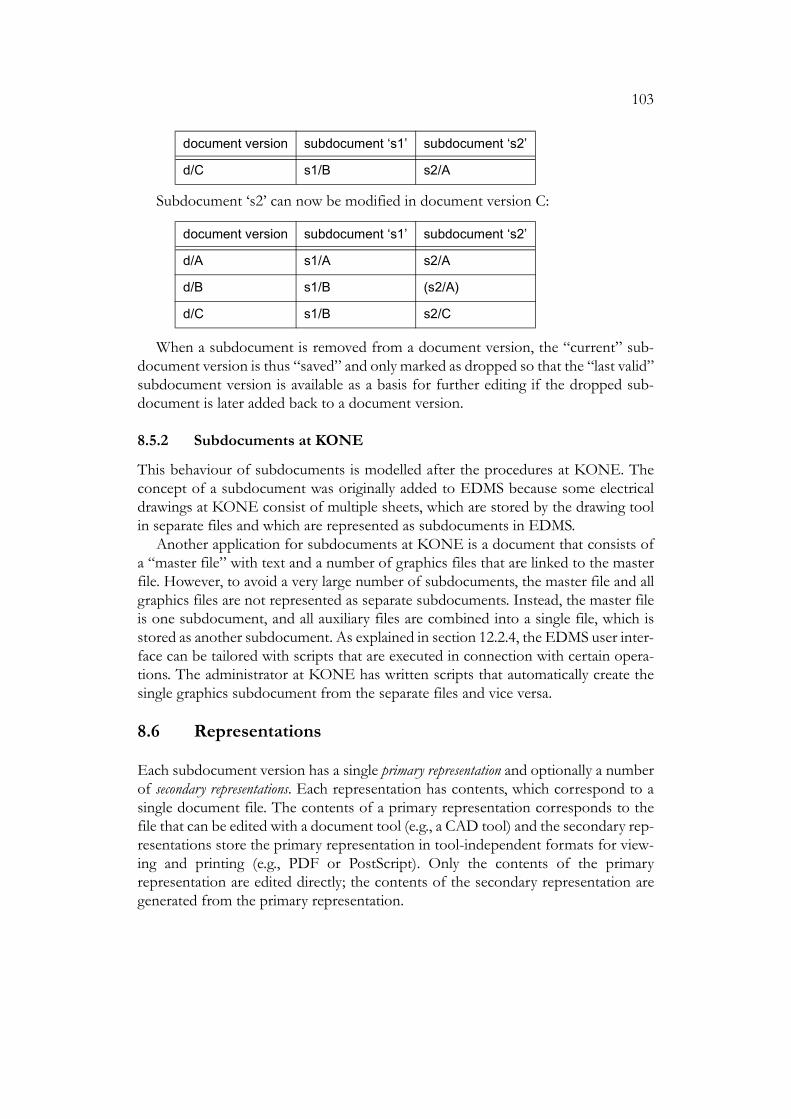
103
Subdocument ‘s2’ can now be modified in document version C:
When a subdocument is removed from a document version, the “current” sub-document version is thus “saved” and only marked as dropped so that the “last valid”subdocument version is available as a basis for further editing if the dropped sub-document is later added back to a document version.
8.5.2 Subdocuments at KONE
This behaviour of subdocuments is modelled after the procedures at KONE. Theconcept of a subdocument was originally added to EDMS because some electricaldrawings at KONE consist of multiple sheets, which are stored by the drawing toolin separate files and which are represented as subdocuments in EDMS.
Another application for subdocuments at KONE is a document that consists ofa “master file” with text and a number of graphics files that are linked to the masterfile. However, to avoid a very large number of subdocuments, the master file and allgraphics files are not represented as separate subdocuments. Instead, the master fileis one subdocument, and all auxiliary files are combined into a single file, which isstored as another subdocument. As explained in section 12.2.4, the EDMS user inter-face can be tailored with scripts that are executed in connection with certain opera-tions. The administrator at KONE has written scripts that automatically create thesingle graphics subdocument from the separate files and vice versa.
8.6 Representations
Each subdocument version has a single primary representation and optionally a numberof secondary representations. Each representation has contents, which correspond to asingle document file. The contents of a primary representation corresponds to thefile that can be edited with a document tool (e.g., a CAD tool) and the secondary rep-resentations store the primary representation in tool-independent formats for view-ing and printing (e.g., PDF or PostScript). Only the contents of the primaryrepresentation are edited directly; the contents of the secondary representation aregenerated from the primary representation.
d/C s1/B s2/A
document version subdocument ‘s1’ subdocument ‘s2’
d/A s1/A s2/A
d/B s1/B (s2/A)
d/C s1/B s2/C
document version subdocument ‘s1’ subdocument ‘s2’

104
The document file associated with a primary representation is updated with a con-ventional check-out / check-in mechanism. The user must first lock a document ver-sion. He or she can then check out a primary representation of a subdocument in thelocked document version. This operation copies the contents of the representationfrom the database to a document file, which is an ordinary file typically located in theuser’s own workstation. The user then manipulates the file with appropriate tools,such as a CAD application in the case of a drawing. When the file is ready, the userchecks in the representation, causing the system to copy the document file to the data-base as the new contents of the primary representation. As explained earlier, at thisstage the system may create a new subdocument version. Finally, the user unlocks thedocument version.
A representation can be in three different states with respect to the check-outoperation. The contents of a primary representation can be empty (no document filehas been stored in the database), checked out (the document file is being edited by auser) or checked in (the document is not being edited). If a document has multiplesubdocuments, the primary representations of multiple subdocuments can be in the‘checked out’ state at the same time. In this case the document version cannot beunlocked until all representations have been checked in.
The ‘lock’ and ‘unlock’ operations are not necessary for the consistency of thedatabase. Without locking, the ‘check-out’ and ‘check-in’ operations would still pre-vent two users from modifying the contents of the same subdocument of the samedocument version at the same time. Nevertheless, the subdocuments are usually soclosely related that it seems better that the whole document version must be lockedfor a particular user before he or she can modify the contents of any subdocumentwithin document version.
In the original user interface the user must explicitly lock and unlock documentversions as explained above. The new user interface is easier to use because it auto-matically locks the document version before a check-out operation and tries tounlock the version after a check-in operation (the unlock operation fails if the pri-mary representation of another subdocument of the same document version is stillchecked out).
A primary representation in the ‘checked out’ state can also be updated and dis-carded. Like check-in, the ‘update’ operation copies a document file to the database.Nevertheless, the representation remains in the ‘checked out’ state for further mod-ifications. The ‘discard’ operation changes the representation back to the ‘checked in’state without updating its contents in the database.
A secondary representation is updated with a replace operation, which is similar tothe ‘check-in’ operation of primary representations and copies a document file to thedatabase as the new contents of the secondary representation. There is no corre-sponding ‘check-out’ operation for secondary representations because their contentsare not edited directly.
A secondary representation records whether its contents are valid with respect tothe primary representation. When the primary representation of a subdocument ver-

105
sion is checked in, all secondary representations of the subdocument version aremarked as invalid. When the contents of a secondary representation are replaced, therepresentation is marked as valid.
Both primary and secondary representations have the operation ‘check out read-only’. This operation simply copies the current contents of the representation fromthe database to a file. This operation leaves no record in the database, and the oper-ation can also be done for a primary representation in the ‘checked out’ state.
At KONE some documents have a PDF file as a secondary representation. A doc-ument tool that does not create a PDF file may create a PostScript file instead. A reg-ularly executed batch program examines all latest document versions in the databaseand replaces PostScript representations with PDF representations.
8.7 Document Components
The target of a ‘check-out’ or a ‘check-in’ operation is not only a particular represen-tation, which belongs to a particular subdocument version. For example, considerfigure 20, which shows the versions of a document and their composition. Documentversion A has child versions B1 and B2. The document has subdocuments ‘s1’ and‘s2’. The second subdocument has been modified in document versions B1 and B2.For example, document version B1 contains subdocument version B1 of subdocu-ment ‘s2’. The first subdocument has not been modified in B1 or B2. All documentversions therefore still contain version A of subdocument ‘s1’.
Suppose a user wants to modify the first subdocument in document version B1.The user locks the document version and checks out the primary representation ofsubdocument ‘s1’ in document version B1. If the ‘check-out’ operation only specifiedthe representation to be checked out, it would be impossible to know which docu-ment version should be modified because all document versions contain the samesubdocument version (i.e., version A of subdocument ‘s1’) with the specified repre-sentation.
Figure 20. Document versions with shared subdocument versions
A
B1 B2
documentversion
subdocuments
s1 s2
d/A s1/A s2/A
d/B1 s1/A s2/B1
d/B2 s1/A s2/B2

106
The document model may be easier to understand if one regards each combina-tion of a document version and a subdocument as a “virtual object” called documentcomponent. A document component is either associated with a single subdocumentversion (which is always a version of the subdocument associated with the documentcomponent) or not associated with any subdocument version. In other words, a doc-ument component represents a cell in the “document composition table”, and eachcell is either empty or occupied with a subdocument version. If a subdocument hasbeen dropped from a document version, the cell is occupied with a subdocument ver-sion but the cell has been marked as dropped.
The document component is a “virtual object” because such objects do not existin the EDMS database. Document components do not have attributes and one can-not make queries on them. Nevertheless, the implementation of the graphical userinterface of the system is based on an object manager (section 12.2.1), which repre-sents document components as a class in the same way as it represents documents,subdocuments and other “real” objects.
8.8 UML Diagram for Documents
Figures 21 and 22 show a UML class diagram and the corresponding constraints forthe document model. The diagram only shows the objects in the database; the “vir-tual” document component objects, which were discussed in the previous section,are not shown.
Constraint 1 says that all documents have different names. Constraints 2 and 3 saythat all versions of a document have different names and all subdocuments of a doc-ument have different names.
As will be explained in section 8.11, each document is of a particular documenttype with a particular name. Constraint 4 says that each version of a document is ofa document version type with the same name as the type of the document. For exam-ple, if a document is of the document type ‘drawing’, all its versions are of the docu-ment version type ‘drawing’.
Constraint 5 says that a document version cannot be its own ancestor. In otherwords, the parent-child relation between document versions must not contain cycles.This constraint uses a non-standard extension to the Object Constraint Language,which is described in appendix A.
Each document version is associated with the subdocument versions that the doc-ument version is composed of. Constraint 6 says that a version of a document canonly be associated with a version of a subdocument of the same document. Con-straint 7 says that a document version cannot be associated with two different ver-sions of the same subdocument. Note that a version of a document does not have tobe associated with a version of every subdocument of the document. Constraint 8says that a subdocument version associated with a particular document version hasthe same name as the document version or the same name as some ancestor of thedocument version. This constraint also uses the non-standard extension.

107
Constraint 9 is similar to constraint 4 and says, for example, that if a document isof a particular document type, all its subdocuments are of a subdocument type withthe same name. Constraint 10 says that all subdocuments of a document have differ-ent names.
Constraint 11 is again similar to constraint 4 and says that all subdocument ver-sions within a document are of the same subdocument version type, which has thesame name as the type of the document. Constraint 12 says that all representationsof a subdocument version have different names. Constraint 13 says that a subdocu-ment version can have secondary representations only if it has a primary representa-tion. Constraint 14 says that a secondary representation is valid if and only if it hasbeen modified (i.e., been given new contents with a ‘replace’ operation) after the cor-responding primary representation has been modified (i.e., has been given new con-tents with a ‘check-in’ operation).

108
Figure 21. UML class diagram of the EDMS document model.Constraints are shown in figure 22.
1
*
1
*parent
0..1
*child
1
*
ObjectType
name
1 1 1
11
**
1..*
*SubdocumentVersion
name
DocumentVersion
name
Subdocument
name
Document
name
dropped: Boolean
*
Representation
namecontentslastModificationTime
*
SecondaryRepresentation
valid: Boolean
PrimaryRepresentation
1 1
0..1
*
*

109
8.9 Projects
EDMS provides very primitive support for projects. A system administrator candefine project types, and attributes (sections 8.11 and 8.12) for each project type.Users can then create projects in the database, store attribute data on the projects andsearch for projects according to the attributes. Nevertheless, the system does not pro-vide any special project management operations. The system should probably not beextended in this direction even in the future.
Database objects can contain attributes that always have the name of a project astheir value. A document, for example, can include an attribute that stores the nameof the project to which the document is connected. One can then make a databasequery that finds all documents with a particular project name for this attribute.
Figure 22. Constraints for document UML diagram.Constraints 5 and 8 use a non-standard notation described in appendix A.
Document(1) Document.allInstances->forAll(d1, d2 | d1 <> d2 implies d1.name <> d2.name)(2) self.documentVersion->forAll(dv1, dv2 | dv1 <> dv2 implies dv1.name <> dv2.name)(3) self.subdocument->forAll(sd1, sd2 | sd1 <> sd2 implies sd1.name <> sd2.name)
DocumentVersion(4) self.objectType.name = self.document.objectType.name(5) not self.(parent+)->includes(self)(6) self.subdocumentVersion->forAll(sdv | sdv.subdocument.document = self.document)(7) self.subdocumentVersion->forAll(sdv1, sdv2 | sdv1 <> sdv2 implies sdv1.subdocument <> sdv2. subdocument)(8) self.subdocumentVersion->forAll(sdv | sdv.name = self.name or self.(parent+)->exists(dv | sdv.name = dv.name))
Subdocument(9) self.objectType.name = self.document.objectType.name(10) self.subdocumentVersion->forAll(sdv1, sdv2 | sdv1 <> sdv2 implies sdv1.name <> sdv2.name)
SubdocumentVersion(11) self.objectType.name = self.subdocument.document.objectType.name(12) (self.primaryRepresentation->union(self.secondaryRepresentation)) ->forAll(r1, r2 | r1 <> r2 implies r1.name <> r2.name)(13) self.primaryRepresentation->isEmpty implies self.secondaryRepresentation->isEmpty(14) self.secondaryRepresentation->forAll(sr | sr.valid = (sr.lastModificationTime > self.primaryRepresentation.lastModificationTime))

110
8.10 Users
The database also stores data about users. The data for a user includes a Unix loginname, which can be empty. If the login name in the database is not empty, a user withthis login name can access the system. A user with an empty login name in the data-base cannot access the system, but the database can contain references to the user.
User names can be used as attribute values in the same way as project names. Forexample, a document can have an attribute that stores a list of users to whom newversions of the document should be delivered. This list can only contain names ofusers who are found in the database.
8.11 Object Types
The administrator must define object types for each object kind. For example, theobject kind ‘document’ could have the object types ‘drawing’ and ‘manual’.
Each object in an EDMS database is of a particular object kind and type. Forexample, each document is of some document type defined by the administrator.
Object types cannot be organised in a class hierarchy. The possibilities to extendthe system in this direction are discussed in section 14.1.5.
The object kinds ‘document’, ‘subdocument’, ‘document version’ and ‘subdocu-ment version’ are related so that when the administrator creates or removes a docu-ment type, the system automatically creates or removes a subdocument type, adocument version type and subdocument version type with the same name.
Related objects always have related types. For example, suppose there is a docu-ment type ‘drawing’ and consider a document of this document type. All subdocu-ments of the document are of the subdocument type ‘drawing’, all versions of thedocument are of the document version type ‘drawing’, and all versions of the sub-documents are of the subdocument version type ‘drawing’. When a new document iscreated, one must specify its type. The type of a subdocument, document version orsubdocument version, however, is never specified by a user because the type is deter-mined by the type of the “containing” document.
Representation types, however, are created and removed independently of docu-ment types. When a new representation is created, its type must be specified becauseit does not depend on the type of the document it is part of.
Object kinds, object types and their relations are illustrated in figure 23. The upperpart of the figure shows the UML classes for object kinds and types. The associationbetween object kinds represents the fact that an object kind (e.g., ‘document’) canserve as a “master kind” to a number of “dependent kinds”. Each object kind is asso-ciated with a number of object types. Constraint 1 says that the object types associ-ated with a single object kind must have different names. Constraint 2 says that anobject kind cannot be both a “master kind” and a “dependent kind”. Constraint 3says for each object type of a “master kind”, each “dependent kind” must have an

111
object type with the same name, and the “dependent kind” cannot have other objecttypes. The lower part of the figure shows the available object kinds and their relations.
8.12 Attributes
Each object in the database, such as a document version or a user, has a number ofattributes, which store various information on the object. Users can set and retrieveattribute values for individual objects and make database queries on the basis of theattributes (e.g., ‘find all document versions that have been approved by user X’).
Each attribute has the following properties:
Figure 23. EDMS object kinds and types
ObjectKind
ObjectType
name
dependentKind
masterKind
*
0..11
*
ObjectKind(1) self.objectType ->forAll(t1, t2 | t1 <> t2 implies t1.name <> t2.name)(2) self.masterKind->isEmpty or self.dependentKind->isEmpty(3) self.dependentKind->forAll(d | self.objectType->collect(name) = d.objectType->collect(name))
document: ObjectKind
subdocument: ObjectKind
documentVersion: ObjectKind
subdocumentVersion: ObjectKind
masterKind
representation: ObjectKind
user: ObjectKind
project: ObjectKind
dependentKind
dependentKind
dependentKind

112
• Name. The name of an attribute is used for referring to the attribute within thesystem. The name is similar to an identifier in programming languages and canonly contain letters, digits and underline characters.
• Title. The graphical user interface of the system displays the titles of the attributesinstead of their names. The attribute title can contain any characters (includingspaces) and be given in different languages.
• Description. The description of an attribute is a longer piece of arbitrary text, whichis displayed by the user interface when a user wants to have more information onthe attribute. The description can be given in different languages in the same wayas the title.
• Value type. The value type of an attribute specifies the allowed values of theattribute. Value types are discussed in section 8.12.5.
• Default value and copy action indicator. Default values are discussed in section 8.12.8.
8.12.1 System Attributes
One of the main goals in the design of EDMS is a flexible database schema definitionmechanism. The system itself only defines a minimal set of system attributes for thevarious object kinds (documents, document versions, etc.). For example, the systemattributes of a document include document name, creation time, and the name of theuser who has created the document.
8.12.2 Type-specific Attributes
As explained in the previous subsection, the EDMS administrator can define anumber of object types. The main purpose of an object type is to define type-specificattributes for objects of that type. An object type definition therefore contains a listof attribute definitions. The previous subsection also explained that certain objectkinds are related. For example, when creating the document type ‘drawing’, theadministrator also creates subdocument type, a document version type and a sub-document version type with the same name. During the creation of a document typethe administrator must therefore supply four attribute lists to specify the attributesof the document type, the attributes of the subdocument type, etc.
8.12.3 Common Attributes
In addition to the type-specific attributes, the administrator can define commonattributes for each object kind. All objects of a particular object kind have the samecommon attributes regardless of the object type.
The system attributes and common attributes of an object kind are collectivelycalled the base attributes of the object kind.

113
8.12.4 Object Types and Attributes Seen as a Hierarchy
The system and common document attributes and the different document types withtheir type-specific attributes can be regarded as a two-level type hierarchy with inher-itance. The system and common attributes are attributes of the type ‘document’. Thedifferent document types defined by the administrator can be seen as subtypes of thesupertype ‘document’ and they can define their own attributes in addition to the“inherited” system and common attributes. Moreover, the supertype ‘document’ isan abstract supertype because no document object is directly an instance of this type.Instead, every document in the database must be of a particular document type.
An object thus has a set of base attributes determined by the object kind (e.g.,‘document’), and a set of type-specific attributes determined by the object type (e.g.,the document type ‘drawing’).
This view on document types and attributes immediately raises the question of amore generalised type mechanism with an arbitrary number of levels. As alreadymentioned, the issue will be discussed in section 14.1.5.
8.12.5 Attribute Value Types
The values that can be given to an attribute are determined by the value type of theattribute. The available value types include the types supported directly by SQL (inte-gers, strings, dates, etc.) and some additional types.
Section 3.2.2.1 mentioned the idea of an ‘attribute type’, which would specify whatinformation is needed in the definition of an attribute of a particular attribute type.EDMS does not have multiple attribute types in this sense because all attribute defi-nitions specify the same information: attribute name, value type, default value, etc.
8.12.5.1 Numeric Value Types
Numeric value types include 32 bit integers and 64 bit floating point numbers. Anumeric value type can optionally specify a minimum and maximum value for theattribute.
8.12.5.2 String Value Type
A character string value type must specify the maximum length of the attribute value.
8.12.5.3 Date and Time Value Type
The value of an attribute with the value type ‘date’ consists of year, month and day.The value of an attribute with the value type ‘time’ consists of year, month, day, hours,minutes and seconds.

114
8.12.5.4 Value Lists and List Item Value Types
If the value type of an attribute is ‘list item’, the value of the attribute is selected froma named value list created by the administrator. For example, the administrator canfirst define the value list ‘languages’ that contains the names of the available lan-guages. A document type can then be defined to include an attribute with the valuetype ‘list-item languages’, which stores any available language name.
Each item in a value list consists of a string that is the actual attribute value, a stringthat describes the value, and an indicator that tells if the item has been deactivated.Consider an attribute with value type ‘list-item L’, and suppose an item with value ‘X’in the value list ‘L’ has been deactivated. The database can now contain objects inwhich the value of the attribute is ‘X’ while it is impossible to give ‘X’ as a new valueto the attribute.
8.12.5.5 User and Project Names
The value type ‘user name’ is similar to ‘list item’. The value of an attribute of thistype is the name of some user in the database. If the value type specifies an optionaluser type, the value of an attribute of this type is the name of a user of the specifieduser type in the database. If the value type does not specify a user type, the name ofany user can be used as a value for the attribute.
Users can be deactivated in the same way as items in a value list. If a user has beendeactivated, the name of the user can remain the value of an attribute but the namecannot be assigned as a new value to an attribute. A user cannot be deleted if thename of the user is used as the value of any attribute with the value type ‘user name’.
Value type ‘project name’ is analogous to the value type ‘user name’.
8.12.5.6 Long Text
A string attribute has a specific maximum length (e.g., 20 characters). An attribute ofthe value type ‘text’ can store a string of arbitrary length. The contents of a textattribute, however, cannot be tested in database queries because the underlying data-base system does not support this operation.
8.12.5.7 Collections
The value types discussed so far have been scalar types, which means that an attributein a particular object stores a single value, such as a single integer or a single string.One of the most important advantages of EDMS over many other similar systems isthe possibility to define the value type of an attribute to be a collection. This meansthat the value of an attribute can consist of multiple elements, and the type of the ele-ments is one of the basic types described above. A single attribute can, for example,store multiple user names instead of a single name.
There are two kinds of collection attributes: sets and sequences. A set does notrecord the order of the elements, nor can it contain duplicates. A sequence is similar

115
to a set except that the order of the elements in a sequence is maintained and dupli-cates are allowed.
8.12.5.8 Multilingual Strings
In a multilingual environment one also needs attributes that store text in multiple lan-guages. For example, the title of a document may be given in Finnish and English.The system therefore has a special value type ‘multilingual string’. The value of anattribute of this type is a set of strings, and each string in the set is of the form ‘lan-guage:text’ where language is an item from the value list ‘languages’. For example,suppose that the title of a document must be stored in different languages. The cor-responding attribute could be a multilingual string and the value of this attributecould be a set with strings “en:Lift cabin” and “fi:Hissin kori”.
8.12.6 Case-Insensitive Search
An attribute stores a string value if its value type is ‘string’, ‘list item’, ‘user name’ or‘project name’. The definition of such an attribute can specify that the attribute allowsa case-insensitive search. For example, if an attribute allows a case-insensitive search,for the string ‘AB’ it finds the values ‘ab’, ‘aB’, ‘Ab’ and ‘AB’ while an ordinary case-sensitive search only finds ‘AB’.
8.12.7 Attribute Indexing
To make object queries faster, the administrator can create indexes on attributes.Indexes are created automatically on attributes that identify the objects. For example,document versions always have indexes on the document name and the versionname.
8.12.8 Default Values
The administrator can specify default values for common and type-specific attributes.In fact, each common and type-specific attribute always has a default value, but thedefault value is a null value if the administrator has not specified any other defaultvalue.
When a user creates a new object and does not supply a value for an attribute, theattribute will usually have the default value. Nevertheless, sometimes a new object ispartly created as a copy of an existing object. For example, suppose that a documentversion has an attribute for the language in which the version is written and anotherattribute for the name of the user who has approved the version. When a new docu-ment version is created as a child to an existing parent version, the value of the ‘lan-guage’ attribute should be copied from the parent version to the new version becausethe attribute probably has the same value in the new version as in the parent version.On the other hand, the value of the ‘approved by’ attribute should obviously not be

116
copied. Instead, the attribute should have the default value (in this case null) in thenew version.
This difference in the behaviour of attributes is specified in an attribute definitionwith a ‘copy action’ setting, which can be either ‘default’ (use the default value) or‘copy’ (copy the attribute value if the new object is created as a partial copy of anexisting object).
8.12.9 Attribute Management
The administrator can add new common and type-specific attributes to an existingdatabase and its object types. Attributes can also be deleted.
The value type of an existing attribute can be changed if the new type is “compat-ible” with the old one. For example, the value type of an attribute can be changedfrom ‘integer’ to ‘floating point number’. Moreover, the value type cannot bechanged if the attribute value in any object is invalid for the new value type. For exam-ple, the maximum length of a string attribute can always be increased, but the maxi-mum length can be decreased only if the current value of the attribute does notexceed the new maximum length in any object (that has the attribute).
8.12.10 Class Diagram for Attributes
A UML diagram and constraints for attributes are shown in figures 24 and 25. Notethat an attribute can be associated with multiple default values because a commonattribute, which is associated with an object kind, has a separate default for eachobject type of the object kind.
Constraint 1 says that an attribute is either a system attribute, a common attributeor a type-specific attribute. Constraint 2 says that all system and common attributesof an object kind must have different names. Constraint 3 says that all type-specificattributes of a particular object type must have different names. Constraint 4 says thata system attribute or a common attribute of an object kind must not have the samename as a type-specific attribute of any object type of the object kind. Constraint 5says that a multilingual string attribute or a text attribute must always be a scalarattribute (i.e., cannot be a set or sequence). Constraint 6 says that an attribute defaultvalue is associated with a type-specific attribute or a common attribute. Constraint 7says that if a default value is associated with a type-specific attribute, then the defaultvalue must be associated with the same object type as the attribute. Similarly, con-straint 8 says that if a default value is associated with a common attribute, then thedefault value must be associated with an object type that is associated with the sameobject kind as the attribute. Finally, constraint 9 says that there cannot be multipledefault values for the same object type and attribute.

117
[This page is left empty to place the following two figures on facing pages.]

118
Figure 24. Class diagram for EDMS attributes.Constraints are shown in figure 25.
0..1
Attribute
nametitledescriptioncopyAction: enum {default, copy}
AttributeType
cardinality: enum {scalar, set, sequence}
AttributeBaseType
TimeAttributeType
DateAttributeType
UserNameAttributeType
ProjectNameAttributeType
ListItemAttributeType
ValueList
namemaxValueLengthmaxDescriptionLength
ValueListItem
value: Stringdescription: Stringdeactivated: Boolean
1*
*1
StringAttributeType
maxLength
1
1
1
1
Multilingual-StringAttributeType
maxLength
system*
common*
*
ObjectKind
ObjectType
0..10..1
*
1
system
Kin
d
com
monK
ind
0..1
*
0..1
*
DefaultValuevalue 1
*
1
*
Text-AttributeType
Integer-AttributeType
IntegerRange-AttributeType
min: Integermax: Integer
Float-AttributeType
FloatRange-AttributeType
min: Realmax: Real

119
8.13 State Graphs
One of the main functions of EDMS is to support document life cycle processes,which typically involve formal approval and release procedures. In many companiesthese well-established procedures have been neglected after the introduction of CADand other computerised document tools.
To model document life cycles, the administrator can define state graphs. Figure26 shows the state graph for document versions at KONE.
In this particular graph the document version is initially in the state ‘draft’. Whenthe version is ready for checking, it is moved to the state ‘ready’. If the version passesthe check, it is moved to the state ‘checked’; otherwise it is returned to the state ‘draft’for corrections. Finally a checked document version must be approved before it isreleased for general use.
The definition of a state graph consists of a set of states, an initial state (which isone of the states in the set), and a set of pairs ⟨old, new⟩ where old and new are two
Figure 25. Constraints for the attribute UML diagram
Attribute(1) self.systemKind->size + self.commonKind->size + self.objectType->size = 1
ObjectKind(2) (self.system->union(self.common))-> forAll(a1, a2 | a1 <> a2 implies a1.name <> a2.name)
ObjectType(3) self.attribute->forAll (a1, a2 | a1 <> a2 implies a1.name <> a2.name)(4) self.attribute->forAll (a | self.objectKind.system->forAll(s | a.name <> s.name) and self.objectKind.common->forAll(c | a.name <> c.name))
AttributeType(5) (self.attributeBaseType->oclIsKindOf(MultilingualStringAttributeType) or self.attributeBaseType->oclIsKindOf(TextAttributeType)) implies self.cardinality = #scalar
DefaultValue(6) self.attribute.objectType->notEmpty or self.attribute.commonKind->notEmpty(7) self.attribute.objectType->notEmpty implies self.objectType = self.attribute.objectType(8) self.attribute.commonKind ->notEmpty implies self.objectType.objectKind = self.attribute.commonKind(9) DefaultValue.allInstances->forAll(d1, d2 | d1 <> d2 implies (d1.objectType <> d2.objectType or d1.attribute <> d2.attribute)

120
states and which means that it possible to move from the state old to the state new.All states must be reachable from the initial state.
The state of a document version is important for determining which operationscan be applied to it. For example, only a draft document version can be modified, andonly an approved document version can be used as a parent for a new version. Theserules are specified with an authorisation mechanism. The state graphs can thus beregarded as a simple workflow mechanism.
The previous state graph is defined for document versions. There can also be aseparate state graph for documents as a whole. Furthermore, different state graphscan be defined for different document types. Actually, the state graph defined for adocument type is only a default graph because it is possible to assign a particulargraph to an individual document or document version regardless of its type. Never-theless, this possibility has not been used at KONE.
Object kinds that support states have system attributes for the name of the stategraph assigned to the object, the name of the current state, the time the object wasmoved to its current state and the name of the user who moved the object to its cur-rent state. At the moment states can be used with documents and document versions.It is easy to add states to other object kinds.
The system attributes only record the current state of an object. There is no built-in mechanism for recording a log of state transitions. A commit procedure (section11.5), however, can be programmed to write an entry to a file or to the database whenthe state of an object is changed.
Figure 27 shows a UML diagram for state graphs. The numbers in parentheses infront of the constraints are not part of the actual constraints; the numbers are onlyfor referring to the constraints in the following description. Constraint 1 says that ifan object type has a default graph, the graph must be associated with the same objectkind as the object type. Constraint 2 says that all state graphs must have differentnames. Constraint 3 says that all states in a particular graph must have differentnames. Constraint 4 says that the initial state of a graph must be one of the states ofthe graph. Constraint 5 says that all states of a graph must be reachable from the ini-tial state. This constraint uses the non-standard extension of the constraint languagedescribed in appendix A. Constraint 6 says that the states that can be reached from astate in a particular graph must belong to the same graph. Constraint 7 says that anobject is associated with a state graph if and only the object is also associated with astate. Constraint 8 says that if an object is associated with a state graph, the graph
Figure 26. Sample EDMS state graph
draft ready checked approved

121
must be associated with the same object kind as the object. Constraint 9 says that ifan object is associated with a state, the state must belong to the graph that is associ-ated with the object. (Constraint 7 guarantees that the object is also associated witha state graph.)
Figure 27. Class diagram for EDMS state graphs.Constraint 5 uses a non-standard extension described in appendix A.
0..1
1
1
1ObjectKind
ObjectType
Object
1*
1*
StateGraph
name
prevState
State
name
initialState
containingGraph1
* containedState
** nextState
0..1*
0..1defaultGraph
*
*
ObjectType(1) self.defaultGraph->notEmpty implies (self.objectKind = self.defaultGraph.objectKind)
StateGraph(2) StateGraph.allInstances->forAll(g1, g2 | g1 <> g2 implies g1.name <> g2.name)(3) self.containedState->forAll(s1, s2 | s1 <> s2 implies s1.name <> s2.name)(4) self.initialState.containingGraph = self(5) self.containedState->forAll(s | s = self.initialState or self.initialState.(nextState+)->includes(self)
State(6) self.nextState->forAll(next | next.containingGraph) = self.containingGraph
Object(7) self.stateGraph->notEmpty = self.State->notEmpty(8) self.stateGraph->notEmpty implies (self.stateGraph.objectKind = self.objectType.objectKind)(9) self.state->notEmpty implies (self.state.containingGraph = self.stateGraph)

122
9 Product Structures in EDMSThe original goal of the project was to develop a system for managing products andrelated documents. The project started with document management because of themore pressing needs and more easily definable requirements in this area. A model forproducts and product structures was developed only much later in the project.
Actually, two different models for product structures have been considered duringthe history of EDMS. Section 9.1 describes the first model, which is based on prod-uct revisions and variants. This model was developed according to the requirementsof KONE and a preliminary implementation was included in the system. Neverthe-less, these product structures were never used at KONE because the companybought the SAP R/3 ERP system, which will eventually store the product structures.However, as mentioned in section 5.5.2, the fact that a company uses an ERP systemthat stores product structures does not necessarily mean that a separate PDM shouldnot deal with product structures. What is needed is a mechanism for sharing productstructures between the two systems.
The model of section 9.1 contains no concept of configurable products or com-ponents with parameters. It is therefore of little interest for the further developmentof EDMS and is described here mainly as historical background to the moreadvanced model.
Section 9.2 outlines the second, more recent, model, which supports configurableproducts and is very similar to Generic Product Structures described by Erens (1996:sec. 4.3). Although the model has not yet been implemented, it has been developedin close co-operation with Rocla Oyj, a Finnish company that manufactures config-urable battery-operated fork-lifts, and some real products of the company have beensuccessfully described with the model. The currently specified product structures aremainly intended to represent the manufacturing structure of a product.
At the moment it seems that the implementation of product structures in EDMSwill be based on the second model with the addition of many details and new con-cepts for managing product evolution. Preliminary ideas on this are given in section9.2.9.
The configuration concepts in this chapter are simpler than those discussed in sec-tion 3.3.2. The more elaborate concepts are also being implemented by the ProductData Management Group. At least initially, however, this implementation will beindependent of EDMS and will mainly serve as a research tool for investigating anddemonstrating the concepts.
9.1 Product Revisions and Variants
The concepts of successive and alternative versions can also be applied to productsand components. The product data model described here, however, is somewhat dif-ferent from the document model. Whereas document versions in EDMS representboth the evolution and different variants of a document, components have separate

123
object kinds for these two purposes. The evolution is represented with componentrevisions, and alternatives with component variants.
Typically the variants of a single component differ only in small details. If one con-siders a drawing or other description of the component, most of the description iscommon to all variants. Revisioning therefore treats all variants of the component asa single unit. When creating a new revision of a component, one actually creates newrevisions of all variants of the component. A component thus has a number of revi-sions, and each revision has a number of variants, as illustrated in figure 22.
9.1.1 Parts
A fundamental property of components is that a component can have other compo-nents as parts, which can again have their own parts, etc. A component that has partsis called an assembly. The terms ‘part’ and ‘assembly’ are relative to the componentbeing considered; a component can be a part in an assembly and at the same time bean assembly of lower level parts.
Different revisions and variants of a component can have different parts. Parts aretherefore connected to component variants, which can contain a number of part ref-erences. Each reference specifies
• the part component (i.e., the component that is used as a part in the assemblycomponent that contains the part reference),
• optionally the variant of the part component,
• the number of part instances, and
• an indicator that tells whether the part is compulsory or optional.
Roughly speaking, the variant of the part component must be specified if the partcomponent has more than one variant.
The number of part instances is a positive integer and tells how many identicalinstances of the part component are included in the assembly.
A compulsory part is always included in the assembly (more precisely, in eachinstance of the assembly in a manufactured product), while an optional part can, butneed not, be included in the assembly.
Figure 28 shows component 12345 with revisions A and B. Variant V3 of revisionB has a single instance of component 45678 and two instances of component 7777as parts. The first part reference further specifies variant V2 of the component; thesecond reference does not specify a variant because the revisions of component 7777have only one variant.
9.1.2 Revision Resolution and Effectivity
A part reference does not specify the revision of the part component. When a prod-uct instance is manufactured, the part reference must be resolved, i.e., the system

124
must select proper component revision for the part components. The reference isresolved each time a product instance is manufactured, and the result depends on theavailable revisions at that time.
A simple (and probably simplistic) method for reference resolution is to use prod-uct revision effectivity. Consider a single component with revisions. In a simplemodel only one of the revisions is effective at any time. The effective revisions can,for example, be found using effectivity dates, i.e., each revision has an effectivity startdate, and possibly also an end date.
Consider again figure 28 and suppose that the revision with the last letter in alpha-betical order is always the effective revision of a component. The system can now beasked to generate the structure of variant V3 of component 12345. The effective revi-sion of component 12345 is B. Variant V3 is thus selected from this revision. Thisvariant has altogether three instances of two kinds of parts. The effective revisions ofboth part components are selected, yielding 45678/C and 7777/B. The first part ref-erence also specifies variant V2. Variant V2 of revision 45678/C is thus selected.
Suppose that a new revision, D, of the component 45678 is created, and this revi-sion no longer has variant V2. An attempt to resolve the part reference to component45678 and variant V2 fails when the new revision becomes effective. Similarly, sup-pose a new revision of component 7777 has more than one variant. The part refer-
Figure 28. Component relationships in EDMS
12345
A
V1
B
V2 V3
component
revisions
variants
45678
A
V1 V1
B
V2
45678
A
V1 V1
B
V1
C
V2
components
revisions
variants
part referencewith variant = V2
part referencewith quantity = 2

125
ence to product 7777 can no longer be resolved because it does not specify thevariant to be selected from the effective revision.
9.2 Product Families
The simple model of the previous subsection will probably not be used as such inEDMS. Instead, product structures will be added according to the ideas presented inthis subsection. The central concept is a product family, which is composed ofgeneric items. A generic item is similar to a configurable product, and a particular var-iant of a generic item is generated by means of parameters, which are used for select-ing correct parts from a conditional parts list.
The basic concepts of this model are by no means new (van Veen 1991;Schönsleben and Oldenkott 1992; Erens 1996). Nevertheless, even today few PDMsystems seem to support configurable products properly.
Sections 9.2.1 to 9.2.5 describe a simple model in which parameters are associatedwith a product family as a whole. This model, however, is probably too simple. Sec-tions 9.2.6 to 9.2.9 therefore outline a more realistic model in which parameters areassociated with individual items. Section 9.2.10 contains a UML diagram of themodel. Finally, section 9.2.11 discusses the limitations of the model.
9.2.1 Product Families and Product Variants
The product range of a company can be grouped into product families. A productfamily consists of product variants, which are in general similar to each other but atthe same time differ from each other with respect to properties that can be specifiedby customers when they make orders.
Note that the term ‘variant’ is used here in the same sense as in section 3.3.2 inconnection with configurable products. A product family can thus have thousands oreven millions of variants, of which typically only a small percentage is ever manufac-tured. This use of the term ‘variant’ differs from sections 3.5.3 and 9.1 in which allvariants of a product or other object are identified and stored explicitly.
Each product variant has its own variant structure, which consists of itemsarranged in the normal fashion into a hierarchical breakdown structure. Each itemrepresents a physical component of the product variant, or work to be done to man-ufacture the product variant, or a document connected to the product variant.
When ordering a product from a product family, the customer must specify thedesired properties of the product. A product family specifies both the input dataneeded for the generation of a variant structure and the rules for generating the var-iant structure from this data.

126
9.2.2 Sales Catalogues, Sales Items and Parameters
A product is ordered by means of a sales catalogue. A sales catalogue presents anumber of alternatives and options to a customer, and the choices made by the cus-tomer guide the generation of a proper variant structure.
Ideally the choices available for customers would correspond directly to the phys-ical components to be included in a product variant. Nevertheless, in practice therelation between the choices made by a customer and the components of a productare more complex. The generation of a variant structure is therefore based on param-eters. A product family has a number of parameters, which must be given valuesbefore a variant structure can be generated. Parameters are discussed in more detailin the next subsection.
Moreover, the sales catalogue does not present parameters to a customer. Instead,the customer selects sales items from the sales catalogue. Each sales item specifies avalue for one or more parameters. The rules that describe the generation of a variantstructure refer to the parameters, not to the sales items.
One benefit of using sales items instead of parameters in a sales catalogue is thatthe sales catalogue can contain predefined “option packages”, which specify valuesfor multiple parameters in the same way as a set of separate sales items. As the variantstructure is generated according to parameter values, it does not matter during thegeneration how the parameter values have been specified. Nevertheless, as prices areconnected to sales items, the price of an “option package” can differ from the totalprice of corresponding separate sales items.
9.2.3 Parameter Lists
Usually a company has many product families with different parameters. Someparameters are specific to a single product family but some parameters are used inmore than one family. To ensure consistent usage of parameters across product fam-ilies within a company, a company has a global parameter list. The definition of aparameter is similar to an attribute definition (section 3.2.2.1) and specifies at leastthe name and value type of the parameter.
As all product families do not have the same parameters, each product has its ownfamily-specific parameter list, which selects parameters from the global parameterlist. When a product family selects a parameter for its parameter list, the product fam-ily can optionally restrict the value type so that the set of allowed values of the param-eter within the product family is a subset of the allowed values in the originalparameter definition in the global list. A product family can also specify a fixed valuefor a parameter, which means that the parameter always has this value within theproduct family and the value cannot be specified in a custom order.

127
9.2.4 Sales Catalogues
A product family is associated with one or more sales catalogues. As mentioned ear-lier, a sales catalogue consists of sales items, and each sales item specifies a value forone or more parameters. A sales item can give a value to a parameter only if theparameter is included in the parameter list of the product family and the family-spe-cific parameter list does not specify a fixed value for the parameter. A sales cataloguecan also specify default values for parameters that do not have a fixed value.
A sales catalogue can contain optional and alternative items. It is also useful if asales catalogue can include additional validity constraints, such as ‘optional item Ccan be selected only if optional items A and B are selected’.
All valid combinations of sales items selected from a sales catalogue must specifya unique value for every parameter of the product family that does not have a fixedor default value.
9.2.5 Parts Lists
When all parameters of a product family have values, it is possible to generate a var-iant structure. As already mentioned, a variant structure is a hierarchically arrangedcollection of items, which represent physical components, work and documents. Aproduct family is associated with a particular item, called the root item of the productfamily, which represents the product as a whole.
Each item can have a parts list, which is basically very much like an ordinary partslist. Each row of a parts list thus contains a position code (e.g., a position number),the code of an item to be included as a part, and a quantity. However, an item and itsparts list are generic in the sense that the variant parts list of an item depends onparameter values, which select a subset of all rows in the generic parts list of the item.To generate a variant structure, one creates a new empty structure, adds the root itemand the items on its variant parts list to the structure, and then recursively processesthe variant parts lists of the new items that were added to the structure.
A parts list of a generic item contains a number of positions, which are identifiedwith the position codes on the rows of the parts list. A variant parts list, whichdescribes a particular variant of the generic item, associates each position with exactlyone item or no item at all.
One simple way to define a generic parts list is to include a selection condition oneach row of the parts list. A selection condition is a logical expression that can referto parameters and use comparison operators (‘=’, ‘<’, etc.) and logical operators(‘and’, ‘or’, etc.). The meaning of a selection condition on a parts list row is that therow is included in the variant parts list only if the present parameter values satisfy thecondition. The condition can also be missing, which means that the row is alwaysincluded regardless of parameter values.
A selection condition on a row makes it easy to represent an optional component,which is either taken to a variant structure or left out depending on parameter values.To represent alternative components, the rows of a parts list are divided into groups,

128
each of which is called a ‘generic part’. All rows that constitute a single generic parthave the same position code, and different generic parts must have different positioncodes. In other words, a generic part as a whole is associated with a single positioncode.
If a generic part contains a single row, this row can contain a selection conditionif the part is optional and should only be selected with particular parameter values. Ifa generic part contains more than one row, each row must have a selection condition.As not more than one item can be associated with a position in a variant parts list, atmost one selection condition within a generic part can be satisfied with any parame-ter value combination.
It must be possible to specify that with some parameter values no item is selectedfor the position associated with a generic part. There are at least two ways to do this.One possibility is to write the selection conditions within a generic part so that anyparameter condition satisfies exactly one condition or no condition at all. In the lattercase, no item is selected for the position.
This rule for selection conditions, however, has the drawback that a generic partdoes not explicitly specify whether the selection conditions are supposed to selectexactly one item or whether the position can also be left empty. In other words, ifparticular values of the parameters do not satisfy any selection condition, it is impos-sible to know whether this is a mistake in the conditions or whether the position isleft empty on purpose.
It therefore seems better to say that the parameter values must always satisfyexactly one selection condition within a generic part (unless the generic part containsa single row, which case is discussed shortly). To represent the case in which a posi-tion is to be left empty, a row in a generic part with multiple rows does not have tospecify an item. If this kind of row is selected, the corresponding position in the var-iant parts list is left empty.
If a generic part contains a single row, and this row has a selection condition, it isnot true that exactly one condition of a group is always satisfied. Nevertheless, thepurpose of the rule “exactly one satisfied condition” is to distinguish between thecases “one of N alternatives” and “one or none of N alternatives”, and this distinc-tion is meaningful only if N > 1.
Given a combination of parameter values, it is easy to check that exactly one ofthe conditions within a group is satisfied. Nevertheless, in general it is impossible tocheck if all parameter value combinations satisfy exactly one condition. In otherwords, this kind of error in the parts list is not detected until a variant structure withparticular parameter values is being generated.
In the approach described above, the selection of parts does not depend on theorder of the rows. Sometimes the conditions would be simpler if the rows in a genericpart were processed in the order in which they are specified in the parts list, and therow with the first satisfied condition was selected to the variant structure. Moreover,the last row could have the code ‘otherwise’ as its condition, meaning that this row isselected if the condition is not satisfied on an earlier row. In other words, the selection

129
of a part would be similar to the ‘if-elseif-else’ construction found in many program-ming languages. Although this construction simplifies the selection conditions, itdoes not record explicitly the condition for selecting a particular part. Therefore, atleast until practical experience is available, it seems better to have unordered rows andrequire that exactly one condition is satisfied.
In addition to an item code and an optional selection condition, a row in a partslist specifies the quantity of the selected item (e.g., ‘1 piece’ or ‘2 m’). The row canalso specify a role for the selected part. For example, the role of a document can be‘installation drawing’, ‘operating instructions’, ‘maintenance manual’, etc.
9.2.6 Item Parameters
The model outlined in the previous section associates all parameters with productfamilies instead of individual items. An item is said to be used by a product family ifthe item is the root item of the family or the item is mentioned in the parts list of anitem used by the family. In other words, a product family uses an item if the item canbe reached from the root item by following the references on the parts lists.
Suppose a product family uses an item, and the parts list of the item has a selectioncondition that refers to a particular parameter. The parameter must then be amongthe parameters of the product family and it must be given a value when a product isordered (unless the product family specifies a fixed value for the parameter).
This simple model assumes that all parameters correspond to properties that arespecified in a customer order. Nevertheless, sometimes an item has a parameter,which is “internal” to the product so that it is unnatural to specify its value directlyin a customer order. Instead, the value of the parameter depends on the values ofother parameters.
It is thus better to associate parameters with individual items. Basically, an item candefine a number of parameters. When a reference to an item B appears on the partslist of item A, the reference must assign values to the parameters of item B. Theassigned parameter value can be specified as a constant or it can be computed fromthe values of the parameters of item A. Parameters that must be given a value whenordering a product from a product family can be represented as parameters of theroot item of the product family. Parameter assignments correspond to conversionfunctions described by Erens (1996: sec. 4.3.9).
For example, item 111 in figure 29 defines parameters A and B. The parts list ofitem 111 contains two rows. The first row selects item 222 if parameter B of item 111equals ‘X’. The second row unconditionally selects item 333 so that the value ofparameter C of item 333 is always 1, and the value of parameter D of item 333 is com-puted from the value of parameter A of item 111.
Many details of this model are still open. For example, it may be convenient if theselection conditions on the parts list of an item can also directly refer to the param-eters of “higher level” items that have this item as a part. This mechanism avoids theneed to write parameter assignments that only copy parameter values from one levelof product structure to lower levels. On the other hand, if the selection conditions in

130
an item refer to the parameters of other items, the first item makes assumptionsabout the context in which it is used. This notion of items having access to a param-eter defined by higher-level items in a product structure is called an external param-eter by Erens (1996: 72, 138).
If an item has a (non-empty) parts list, the parameters of the item are used in selec-tion conditions to select rows from the parts list. Parameters can also be used inparameter assignments to specify values for the parameters of the selected items. If,however, an item is primitive in the sense that is does not have a parts list, the itemcan still have parameters. In this case the parameters together with their values areincluded in the variant structure, which is used as a basis for manufacturing the prod-uct variant. For example, a product can contain a steel rod, which can be manufac-tured to an arbitrary length within certain limits and with certain precision (e.g., 100–200 cm in steps of 1 cm). The steel rod can be represented as an item that has aparameter for the length. The parameter is not used for selecting an appropriate rodfrom a predefined set of rods with different lengths. Instead, the value is included assuch in the variant structure.
If items have parameters, one must also decide whether the items still select theirparameters from a global parameter list. If not, two items can probably define param-eters with the same name. If the selection conditions on a parts list can refer to theparameters of other items, as suggested in the previous paragraph, and two items canhave parameters with the same name, a reference to a parameter must specify theitem in which the parameter is defined in addition to the name of the parameter.
9.2.7 Parameters and Attributes
If items define parameters as described above, what is the relation between attributesdefined by object types and parameters defined by items? One possibility would beto represent each item as an object type, which could then define the parameters of
Figure 29. Example of a parts list with parameters
item 111parameters: A:int, B:choice{X, Y}parts list
item 222parameters: -
item 333parameters: C:int, D:int
position item parameter assignments selection condition
1 222 B = ‘X’
2 333 C = 1, D = A + 2

131
the item as attributes. In principle this could be an elegant solution because parame-ters could then be manipulated with the existing attribute mechanism. Nevertheless,a database would then contain thousands of object types, and as was discussed in sec-tion 5.2, the present implementation of object types and attributes is designed for amuch smaller number of object types.
It thus seems that there must be a relatively small number of item types. Each itemis an instance of some item type and has values for the attributes defined by the itemtype. Each item can then define parameters.
If a variant structure contains items that have parameters, the structure must actu-ally contain an item instance, which has values for all parameters of the item. If anitem does not have parameters, there is no difference between the item and itsinstances.
9.2.8 Global Parameter Assignments
The idea that parameters are associated with items instead of product families wasmotivated by the fact that it should be possible to determine the values of “derived”parameters on the basis of “primary” parameters, which are given values in a cus-tomer order.
There are other ways to compute parameter values from other parameters. Sup-pose that parameters are associated with product families as in the first model. Partslists could be extended so that in addition to selecting items as parts, a row in a partslist could give a value to a parameter of the product family This kind of row wouldhave the same kind of selection condition as rows that select items.
Now all parameters of the product do not have to be given values before the prod-uct variant is generated because additional values are determined while the parts listsare examined.
Although this model may seem a simple extension to the original model, it hasproblems. One problem is to ensure that all parameters that need a value have anunambiguous value. If a selection condition refers to a parameter, this parametermust have been given a value before the condition is tested. If a parameter has beengiven a value, either in the customer order or through a value assignment in a partslist, no parts list must try to give another value to the parameter. The “global valueassignments” also make it impossible to have two instances of the same item with dif-ferent parameter values in a single product variant.
9.2.9 Versioning within Product Families
The product family model outlined in this section must be extended by some mech-anism to deal with the evolution of product families and the items they are composedof. No definite solution is proposed here, as even the details of the basic model with-out versioning are still open.
Before the versioning of items can be discussed, one must know what informationis associated with an item and which part of this information, if any in addition to the

132
item code, is common to all versions of an item and what information can differbetween versions. If an item is associated with a set of parameters and a parts list, atleast the parts list, and probably also the parameters, can be different in different ver-sions of the item.
The two basic versioning concepts are revisions and variants, which are treatedseparately in the following discussion.
As a result of the parameters, an item has a number of “implicit” variants, whichare generated with different combinations of the possible parameter values. In the-ory, this parameter-based variation could be combined with the “explicit” variants ofsection 9.1. Each variant of an item would have its own parts list, and a reference toan item in a parts list would specify both an item and its variant. In practice, however,this kind of model is only confusing because the same effect can be achieved withparameters. After all, the code for identifying different explicit variants is simply aparameter, which can be used in the parts list in the same way as other parameters.
As parameters take care of variants, the versioning of items is reduced to the ques-tion of dealing with revisions, which represent the evolution of items. Basically, theissues are very similar to those already discussed in section 9.1. An item consists of asequence of revisions. Each revision has its own set of parameters and parts list. If areference to an item on a parts list does not specify a revision, the reference is genericand must be resolved when the reference is encountered during the generation of avariant structure. The resolution can, for example, be based on revision effectivity.
A reference to an item on a parts list does not have to specify a revision. As dif-ferent revisions of an item can have different parameters, it is possible that a refer-ence that specifies a value to a particular parameter becomes invalid because thereference is resolved to a new item revision that does not have the parameter. Simi-larly, the new revision may have a new parameter, which is not given a value in thereference.
9.2.10 Initial Data Model for Product Structures
This section contains a data model for product structures in which parameters areassociated with individual items. The model must be regarded as an initial versionbecause it has not yet been implemented. The model does not support the idea thata selection condition could refer to parameters defined by items higher in the productstructure. The model includes constraints for checking whether a reference to a par-ticular item can be bound to a particular revision of the item as far as parameterassignments are concerned. Nevertheless, the model does not say anything abouthow the revision is actually selected.
Figures 30 and 31 show the initial UML class diagram for product family struc-tures. Each item has a number of revisions. Each item revision can define parameters.A parameter definition associated with an item revision specifies a parameter andoptionally a default value for the parameter.
An item revision is associated with a sales catalogue if the item represents a prod-uct that can be sold to customers. A sales catalogue contains sales item groups, which

133
in turn consist of sales items. A sales item group specifies the minimum and maxi-mum number of items that can be selected from the items in the group. For example,if the minimum number is 0 and the maximum number is 1, the group selects a setof alternative sales items from which a user can optionally select at most one item.Each sales item specifies a code and a price and assigns values to one or more param-eters defined by the item revision. A sales catalogue can include constraints that fur-ther restrict the selection of sales items. The detailed format of the constraints is stillunspecified.
Constraint 1 specifies the allowed range for the minimum and maximum numberof choices in a sales item group. Constraint 2 says that a sales item cannot assign twovalues to a single parameter, and constraint 3 says that a sales item can only assignvalues to parameters that are defined by the item revision associated with the salescatalogue.
An item revision can also be associated with parameter constraints. Each param-eter constraint is a logical expression (i.e., an expression that evaluates to true orfalse), which must be satisfied by the parameter values when the item revision is usedin a variant structure. Each parameter constraint is associated with the parametersthat the expression refers to. UML constraint 4 of figure 25 says that a parameter con-straint can only refer to parameters defined by the item revision that the constraint isassociated with.
An item revision is associated with zero or more generic parts, which togetherconstitute the parts list of the item revision. Each generic part has a position code,and the generic parts in a single parts list must have different position codes (con-straint 5). A generic part contains one or more parts, which correspond to the rowsof a parts list. A part has a role as an attribute. Unless a part specifies that the corre-sponding position in the parts list should be left empty, a part is associated with anitem reference. At least one part in a generic part must refer to an item (constraint 6),and if a generic part contains more than one part, all parts in the group must have aselection condition (constraint 7). A part specifies a quantity if and only if it also spec-ifies an item (constraint 8).
An item reference specifies an item and assigns values to the parameters of thespecified item. A parameter assignment in an item reference specifies a single param-eter to which a value is assigned. The assigned value is specified by means of anexpression that can refer to other parameters.
When a variant structure is created, an item reference is bound to some revisionof the item specified in the reference. As different revisions of an item can define dif-ferent parameters, the parameter assignments in an item reference are not necessarilyvalid for all revisions of the item specified by the reference (the validity rules are givenshortly). The dashed line represents the association between an item reference andthe item revisions that the reference can be bound to. This association is marked witha dashed line because an item reference does not directly specify the possible itemrevisions, and the association is not stored explicitly in the system. Instead, the valid-ity of parameter assignments is probably only checked after an item revision has beenselected as a “candidate” for the target of an item reference.

134
Figure 30. Initial data model for product structures in EDMS. The dashed line, which is not part of the standard UML notation, is explained in the text.
Constraints for the diagram are shown in figure 31.
Parameter
namevalueType
Item
ItemRevision
GenericPart
positionCode
Part
role
1*
1
**
ParameterConstraint
constraint:LogicalExpression
ParameterDefinition
ParameterDefaultValue
value: Literal
1
0..1
1 * 1*
1
*
*
1
1..*
ItemReference
ParameterAssignment
value: Expression
assig
ned
Para
mete
r
1 used
Para
mete
r
*
* *10..1
1 *
*
**
1
Quantity
unitnumber: NumericExpression
0..1
SelectionCondition
condition: LogicalExpression
11
0..1
*
*
*
*
SalesCatalogue
SalesItemGroup
minChoices: IntegermaxChoices: Integer
SalesItem
codeprice
SalesParameterAssignment
value: Literal
1..*1
1..*1
SalesItemConstraint
*1
1..*
11
*
1
*

135
Figure 31. Constraints for the product structure UML diagram
SalesItemGroup(1) self.minChoices >= 0 and self.maxChoices >= self.minChoices and self.maxChoices <= self.salesItem->size
SalesItem(2) self.salesParameterAssignment->forAll(a1, a2 | a1 <> a2 implies a1.parameter <> a2.parameter)
SalesParameterAssignment(3) self.salesItem.salesItemGroup.salesCatalogue.itemRevision .parameterDefinition.parameter->includes(self.parameter)
ParameterConstraint(4) self.ItemRevision.parameterDefinition.parameter ->includesAll(self.parameter)
ItemRevision(5) self.GenericPart->forAll(g1, g2 | g1 <> g2 implies g1.positionCode <> g2.positionCode)
GenericPart(6) self.part->exists(p | p.itemReference->notEmpty) (7) self.part->size > 1 implies self.part->forAll(p | p.selectionCondition->notEmpty)
Part(8) self.itemReference->notEmpty = self.quantity->notEmpty
ItemReference(9) self.itemRevision->forAll(r | r.item = self.item)(10) self.parameterAssignment->forAll(a1, a2 | a1 <> a2 implies a1.assignedParameter <> a2.assignedParameter)(11) self.itemRevision.parameterDefinition.parameter ->includesAll(self.parameterAssignment.assignedParameter)(12) self.itemRevision->forAll(r | r.parameterDefinition->forAll(d | d.parameterDefaultValue->notEmpty or self.parameterAssignment.assignedParameter->includes(d.parameter)))
ParameterAssignment(13) self.itemReference.part.GenericPart.itemRevision. parameterDefinition.parameter->includesAll(self.usedParameter)
Quantity(14) self.part.GenericPart.itemRevision .parameterDefinition.parameter->includesAll(self.parameter)
SelectionCondition(15) self.part.GenericPart.itemRevision .parameterDefinition.parameter->includesAll(self.parameter)

136
Constraint 9 says that an item reference can be bound to a revision of the itemspecified in the reference. Constraint 10 says that an item reference cannot assignmultiple values to a parameter. Constraint 11 says that an item reference can onlyassign values to parameters that are defined by the item revision that the reference isbound to. Finally, constraint 12 says that when an item reference is bound to an itemrevision, the item reference must assign a value to all those parameters defined by theitem revision that do not have a default value.
The parameter value in a parameter assignment is specified with an expressionthat can refer to the parameters defined by the item revision that contains the partwith the assignment (constraint 13). Similarly, the quantity and selection condition ofa part can refer to the parameters of the item revision that contains the part (con-straints 14 and 15).
In section 3.3.2, a configuration model was said to consist of an explicit structure,constraints and generation procedures. Constraints were further divided into specifi-cation constraints, implementation constraints and structural constraints. TheEDMS product model represents the explicit structure as parts lists, generic partsand parts. Specification constraints are represented as parameter constraints. TheEDMS model does not contain implementation constraints because the selectionconditions should rather be interpreted as simple generation procedures. The modelpresented so far does not contain structural constraints either, but their possibleaddition to the model will be discussed shortly.
9.2.11 Limitations of the Parameter-Based Approach
The parameter-based method described in this section is straightforward and itshould be suitable for the description of many configurable products. Nevertheless,the method has its limitations.
Section 3.3.2 on configurable products introduced (1) an explicit structure, whichdescribes the unrestricted set of potential configurations, (2) constraints, whichdefine the valid configurations within the set defined by the explicit structure, and (3)procedures, which help a user to create valid configurations.
The parameter-based approach to product families deals mainly with issues 1 and3 above. The explicit structure is defined by the generic parts and the parts. The selec-tion conditions define a simple mapping from parameter values, which represent thedesired properties of a product variant, to a variant structure, which describes thecomponents of a product variant.
Nevertheless, the parameter method provides no way to define explicit constraintsfor the variant structure. For example, it is impossible to specify that a single variantstructure cannot contain both item A and item B, or that if a variant structure con-tains item C, it must also contain item D. It remains the responsibility of the authorof the selection conditions to make sure that, for example, no combination of param-eter values satisfies the selection conditions of the two incompatible items A and B.
It may be useful to add “structural” constraints, such as ‘items A and B are incom-patible’ or ‘item C requires item D’, to the present model. These constraints make it

137
possible to define additional validity checks for a variant structure, which is generatedwith the selection conditions. If the system notices that a variant structure violates astructural constraint, the system cannot do more than inform the user on the prob-lem, which indicates an error in the selection conditions.
Obviously it would be better if the system could directly check the selection con-ditions, instead of individual generated variant structures, against the structural con-straints. However, this task is difficult in the same way as the task of checking thatevery parameter value combination satisfies exactly one selection condition in eachgeneric part.
The selection conditions are a straightforward way to define configuration proce-dures. If the product is simple enough, as many products are, this mechanism is prob-ably quite good because of its simplicity. Nevertheless, there are configurationproblems that cannot be solved with such means.
The parameter approach assumes that for any customer specification, representedwith parameters, there is exactly one variant structure. However, there are productsin which a specification can be fulfilled with a number of alternative product struc-tures, and the final choice between the alternatives is made with some additional cri-terion, such as cost or delivery time, which may depend on the inventories anddelivery times of different components.
In this case it is often impossible to write a “deterministic” procedure that gener-ates the “best” configuration. Instead, the configuration must be searched for with“trial and error” methods, such as backtracking, investigated in artificial intelligenceand logic programming.

138
10 EDMS Architecture OverviewThe main components of the system are shown in figure 32. All data, including therepresentation contents, are stored in a commercial relational database. The databaseis accessed through the EDMS server program, which accepts service requests fromclient programs. The clients communicate with the server using a protocol developedfor this purpose. The server is discussed in more detail in chapter 11. The mostimportant clients include the ‘access’ program (section 12.1), graphical user interfaces(sections 12.2 ), an Application Programming Interface to integrate EDMS with doc-ument tools (section 12.3) and a Web server (section 12.4).
In addition to clients, the server can also be contacted by ‘monitor’ programs,which send simple commands to the server. The monitor commands include com-mands for printing information about the clients that are currently connected to the
Figure 32. EDMS system architecture
design tool
monitor
database
EDMS server
EDMS API
user interface
object manager
relational database system
filesystem
Web server
Web browser
access
client machine
server machine
administrator’smachine

139
server, and debug commands for setting the server in a mode in which it prints allservice requests received by all clients or a selected client.
The client programs and monitor programs communicate with the server overTCP/IP socket connections. An encryption facility, such as SSL (Secure SocketLayer), will probably be added later.

140
11 EDMS ServerThe server program implements the EDMS data model on a relational database.EDMS clients access the server by sending service requests defined in the server pro-tocol.
11.1 Server Protocol
The server protocol defines about 120 requests and corresponding replies (Peltonen1993). The communication between the clients and the server is synchronous. Theserver basically executes a loop in which it reads a request from a client, carries outthe operation specified by the request, sends a reply to the client, and is ready to readthe next request from the same or another client.
The protocol defines a new abstraction level on top of a relational database. Allrequests refer to the concepts of the EDMS data model, such as documents and doc-ument versions. The implementation of these concepts in a relational database is hid-den within the server. If the present database is replaced with another database, theserver has to be modified, but no changes are needed in the protocol. Since the userinterface and other clients access the database through the protocol, the clients neednot be modified either.
Set-valued attributes are a good example of the higher abstraction level of the pro-tocol. The complexity of implementing sets in a relational database does not show upin the server protocol, which handles set-valued attributes in much the same way assimple attributes. The server protocol has proved very useful as an abstraction mech-anism for concepts that are not found directly in relational databases but can be con-veniently implemented in the server.
The requests and replies consist of plain text with a syntax similar to the Lisp lan-guage. Each request and reply is a parenthesised list that contains strings, numbersand parenthesised sublists.
11.1.1 Schema and Data Manipulation Requests
The protocol contains requests that modify and query the database schema, such asobject types and their attributes, and requests that modify and query the actual data,such as documents and their versions. Figure 33 shows an example of a schema mod-ification request, which adds a common attribute to documents. A type-specificattribute would be added by replacing the word ‘COMMON’ with the name of a doc-ument type. The attributes have a specific order, and the new attribute is added afteran attribute with name ‘department’. The name of the attribute is ‘person_in_charge’,its title is ‘Person in charge’ in English and ‘Vastuuhenkilö’ in Finnish. The descrip-tion of the attribute is also given in English and Finnish. The value type of theattribute is ‘user name’.

141
Figure 34 shows an example of a data manipulation request, which creates a newdocument version. The version is created in document ‘1234’. The name of the newversion is ‘fi.C.1’ and is created as a child to version ‘fi.B.1’. The attribute ‘priority’ ofthe new version is given the value ‘urgent’. The value type of this kind of attributewould typically be ‘list item’. The attribute ‘completion_date’ of the value type ‘date’is given the value ‘31 March 2000’. As can be seen from the request, date and timevalues are represented in the protocol in Unix format (seconds after 1 January 1970).
11.1.2 Compound Requests
A single server request may involve several updates in the database. The server proc-esses each request as a single database transaction. The database is thus never left inan inconsistent state after any failure during the processing of a request. Neverthe-less, sometimes a single logical operation consists of several separate requests. Forinstance, the user interface provides an operation that creates a new documenttogether with a subdocument and the first document version. This operation takesseveral requests: ‘create document’, ‘create subdocument’, etc.
It would be convenient for the server protocol to include a mechanism for exe-cuting an arbitrary sequence of requests as a single transaction. The protocol would
Figure 33. Sample schema manipulation request
Figure 34. Sample data manipulation request
(add-attribute document COMMON after department
(person_in_charge
("Person in charge" (fi "Vastuuhenkilö"))
("The name of the person …" (fi "…"))
(user-name)))
object object type or name ofkind “COMMON” existing attribute
name of thenew attribute
title in Englishand in Finnish
description
value type
(create-document-version "1234" fi.C.1 (fi.B.1)
((priority "urgent") (completion_date 954460800) …))
name ofparent version
name ofnew version
name ofdocument
name ofattribute
value ofattribute

142
include two new requests for starting and committing a transaction, and requestsbetween these two requests would constitute a single transaction.
Unfortunately, it is impossible to implement this kind of mechanism with a nor-mal database system. If the clients could start and commit transactions with separaterequests, there could be several active transactions at the same time. However, theserver is a single database application and the database systems usually allow eachapplication to execute only a single transaction at a time.
Although separate requests for starting and committing transactions are infeasi-ble, a simpler mechanism is included in the server. A request sent by a client to theserver can be a compound request, which consists of a number separate requests that areexecuted as a single transaction. Figure 35 shows a compound request that corre-sponds to the operation ‘create document with structure’ in the user interface.
If a compound request fails, all its effects in the server and in the database mustbe rolled back. Database updates are easy to cancel because this operation is directlyavailable as the database roll-back operation. It is, however, more difficult to roll backthe modifications made in the internal data structures of the server application.
A compound request can therefore only contain requests that only update thedatabase but do not modify any server data structures. In practice this means thatcompound requests can contain data manipulation operations (e.g., ‘create a newdocument’) but cannot contain schema manipulation operations (e.g., ‘create a newdocument type’).
11.2 Subservers
Most requests are executed “quickly”; more precisely, if access to a relational databasethrough an indexed column is considered to take a constant time, most server
Figure 35. Compound request
((create-document "1234" drawing (…))
(create-subdocument "1234" main (…))
(create-document-version "1234" fi.-.1 () (…))
(create-subdocument-version "1234" fi.-.1 main (…))
(lock-document-version "1234" fi.-.1)
(create-representation "1234" fi.-.1 main CAD
primary CAD_rep (…))
(unlock-document-version "1234" fi.-.1))
‘1234’ = document name‘drawing’ = document type‘…’ = attribute names and values‘main’ = subdocument name
‘fi.-.1’ = document version name‘CAD’ = representation name‘primary’ = create primary rep‘CAD_rep’ = representation type

143
requests are executed in roughly constant time. Some requests, however, can take amuch longer time. The protocol includes a request for an arbitrary query. If the querycontains a condition for an attribute that has not been indexed, the query has to makea sequential scan over the whole database. The check-out and check-in operations,which transfer representation contents between clients and the server, may also takea long time depending on the representation size and the data transfer rate betweenthe client and the server. It would be unacceptable if the server did not accept anyrequests from other clients during these long operations.
This problem has been solved with subservers. Queries and copy operations arenot executed directly by the server. Instead, the server launches a separate subserverprocess, which executes the time-consuming operations. Each client has its own sub-server process. The process is started when the client sends the first request thatrequires the subserver and terminated when the client connection is closed. Whenthe main server is started, one can specify the maximum number of concurrent sub-servers. If the server has to start a new subserver for a client and the maximumnumber of subservers has been reached, the server first terminates the subserver thathas been idle for the longest time.
After the main server has forwarded a request to a subserver, the main server canprocess requests from other clients. To avoid conflicting access, the main servermaintains a data structure that tells which representations are currently being copiedby subservers.
The contents of an EDMS representation are copied from the database to a user’sfile with a check-out operation, and from a file to the database with a check-in oper-ation. The copying can take a long time depending on the amount of data to be cop-ied and the speed of the network between the server and the client. Representationsare therefore copied by the subserver over a direct socket connection between theclient and the subserver.
To reduce the amount of data to be transferred, the contents of representationsare compressed with the publicly available ‘gzip’ program before they are transferredfrom the server to a client or vice versa. The contents are also stored in the databasein the compressed format.
11.3 Server Notifications
In the basic client-server model the server sends replies to requests from the clientsbut never sends anything to the clients on its own initiative. The EDMS server, how-ever, sends server notifications to the clients. A client can register an object, e.g. adocument or a document version. When the server modifies the object, e.g., a docu-ment by creating a new version of it or a document version by locking it, the serversends a notification message to all clients that have registered the affected object.Server notifications are sent over a separate socket connection between a client anda server.

144
Server notifications are not sent for any schema modifications, such as the crea-tion of a document type or modification of an attribute type.
Although this notification mechanism is elegant, its implementation is somewhatunreliable. It also seems difficult to make the new Java user interface client read theasynchronous notification messages over a separate socket connection. The presentnotification mechanism will probably be replaced with a simpler mechanism in whichthe clients receive the notifications as part of ordinary server replies. This means thata client does not become aware of the relevant modifications until the next time itsends a request to the server.
11.4 Authorisation Procedures
An engineering management system must include a flexible authorisation mechanismfor specifying which users are allowed to perform various operations under variouscircumstances.
In the Unix operating system, each file is assigned to an owner, i.e., a user, and auser group. The owner of the file can specify read and write privileges separately forthe owner, for the group and all other users. A much more flexible mechanism wasneeded for EDMS.
For example, whether a document version can be changed, depends not only onthe user and the identity of the document, but also on the current status of the doc-ument version. As another example, suppose each document is assigned to a depart-ment and each department has a manager. One could then have a rule that adocument version can only be approved by the manager of the department to whichthe document whose version is being approved has been assigned.
EDMS handles authorisation by means of an authorisation program. The pro-gram can contain an authorisation procedure for each server request that modifiesthe database. The procedures, which are written in a special language designed forthis purpose, can read attribute values and make database queries (Peltonen et al.1994a). In addition to modification requests, an authorisation procedure is executedwhen a user wants to have a read-only copy of the contents of a representation (i.e.,a copy of a document file). Although the present authorisation mechanism cannotcontrol users’ rights to read individual attribute values, it is possible to define filterconditions, which completely hide particular documents and projects from particularusers.
When the server is started, it reads the authorisation program from a file specifiedas command line argument. Whenever the server receives a request from a client, theserver first executes the corresponding authorisation procedure, which must eventu-ally execute either an ‘accept’ or a ‘reject’ statement. If the procedure executes a‘reject’ statement, the server does not perform the operation requested by the clientand sends an error reply, which includes an error message specified in the ‘reject’statement.

145
As an example of authorisation procedures used at KONE, suppose documentversions are associated with the state graph that was shown in figure 26 on page 120.The authorisation program should enforce the rule that a document version can nor-mally be locked only when it is in the state ‘draft’. As an exception, the user‘edms_admin’ can lock a document version regardless of its current state. The rulewould be described with the authorisation procedure in figure 36.
As a more complex example from KONE, consider the creation of a new docu-ment version in the versioning scheme that was illustrated in figure 19 on page 99.The authorisation procedure for document version creation does the followingchecks:
• If the new version with the name ‘xx.Y.n’ is created as a child to an existing parentversion, the name of the parent version must begin with the same language code‘xx’.
• If the new version is created without a parent (i.e., as the first version of a newlanguage), no existing version of the document is allowed to have a name thatbegins with the same language code as the new version.
The authorisation procedures are executed by the server when it receives a requestfrom a client. For instance, suppose a user is creating a new document and entersattribute values in the ‘create document’ dialogue of the user interface. When the userhas filled the dialogue, the user interface client sends a single ‘create document’request with the attribute values to the server. The server then executes an authori-sation procedure, which can check the attribute values and reject the request if nec-essary.
In addition to constructs for accessing the attributes of documents and otherEDMS objects, authorisation procedures can query the database by means of arbi-trary SQL ‘select’ statements. This mechanism allows the administrator to create
Figure 36. Sample authorisation procedure
event lockDocVersion (user, version)
if user = "edms_admin" then
accept;
end;
if version.current_state = "draft"
then
accept;
else
reject "must be in state 'draft'";
end;
end;

146
additional tables with data that can be read by the authorisation procedures. The que-ries can also read the tables that contain the EDMS objects. Nevertheless, to readthese tables, the administrator must know how the EDMS objects and attributes arerepresented as tables and columns in the relational database. It would of course bemore convenient if the queries could be formulated in some “extended SQL” thatwould correspond more directly to the concepts of the EDMS data model (Keim,Kriegel and Miethsam 1993).
The authorisation procedures thus have the disadvantage that they cannot checkanything immediately after the user has entered a value in the user interface. On theother hand, now that the authorisation procedures are implemented in the server, theprocedures are always applied to all requests from all clients.
There are separate authorisation procedures for the data manipulation requests‘create document’, ‘create document version’, ‘change attribute values’, etc. Allschema manipulations, such as ‘create document type’, call a single authorisation pro-cedure ‘modifySchema’, which has no other arguments than the name of the user thatissued the request. Typically only the system administrator is allowed to modify theschema, and it is not necessary to distinguish between different kinds of schemamodifications within the authorisation procedure.
Typically a graphical user interface allows a user to select an object and then dis-plays the available operations as (activated) push buttons and menu items. Even whenthe user interface determines that a particular operation can be executed accordingto the general rules of EDMS, the operation may still be rejected by an authorisationprocedure. A client can determine if an operation is available to the user by means ofa request called ‘check-request’ that has another request as a parameter. When theserver receives a ‘check-request’ request, it checks if the request given as a parametercould be executed. If not, ‘check-request’ returns the same error reply that would bereturned by the parameter request; otherwise, the server returns ‘ok’ without actuallyexecuting the parameter request.
11.5 Commit Procedures
Commit procedures are similar to authorisation procedures. Whereas an authorisa-tion procedure checks whether an operation is allowed, a commit procedure canmodify attribute values. The name comes from the fact that the server executes theseprocedures immediately before committing a transaction, i.e., before storing themodified data permanently in the database.
At KONE, document versions have been defined to contain the attributes‘checked_by’ and ‘approved_by’ that disclose the names of the users who havechecked and approved the version. When a document version is moved to a newstate, the commit procedure in figure 37 automatically updates the attributes as nec-essary.
Appendix B contains a more complex example of a real commit procedure usedat KONE.

147
Commit procedures, as well as authorisation procedures, can also send e-mail,write messages to a log file and insert log records into the database. This mechanismcan, for example, be used for creating an audit trail of database updates.
11.6 User Authentication
While the purpose of an authorisation mechanism is to determine whether user ‘xyz’is allowed to carry out a particular operation, the purpose of an authentication mech-anism is to determine reliably that the person who logs into the system as user ‘xyz’really is that person.
User authentication in EDMS is based on passwords. When a client program con-nects to the server, the client must first send a ‘set-user’ request, which specifies auser name and a password. The server then compares the password in the requestwith the password stored in the database.
When the server is started, one can optionally specify the address of a WindowsNT authentication server and a domain name. In this case, the server first checks thepassword in the ‘set-user’ with the NT server. A user who has already been registeredin the NT server thus does not need a separate password for EDMS.
11.7 Object Filters
Authorisation procedures only control operations that modify the database as well asthe operation that copies the contents of a representation to a client for read-onlyuse. However, a company may also want to restrict users’ rights to see attribute valuesin the database.
In principle, an authorisation procedure could be called before the server sendsan attribute value to a client. Nevertheless, if would be far too inefficient to call an
Figure 37. Sample commit procedure
event changeState (user, obj, newState)
if kind(obj) = "doc-version" then
test newState
when "draft":
update obj.checked_by := NULL;
update obj.approved_by := NULL;
when "checked":
update obj.checked_by := user;
when "approved":
update obj.approved_by := user;
end;
end;
end;

148
authorisation procedure for every attribute of every object returned by a databasequery.
Although access to individual attributes cannot currently be controlled, theadministrator can define object filters, which hide selected documents, users andprojects from selected users. To define a filter, an authorisation procedure can call thebuilt-in procedure ‘set_filter_condition’ with arguments that specify an object kind,optionally an object type, and a condition on the attributes of the specified objectkind and type. (If object type is not specified, the filter applies to all objects of thespecified kind.) As a result of the call, a filter condition is added to all queries on thespecified objects in the client session in which the filter was defined. If the attributevalues of an object do not satisfy the filter condition, the server behaves from the cli-ent’s point of view as if the object did not exist. An object that does not satisfy thefilter condition is thus “hidden” from the client (with some exceptions discussedshortly). The procedure ‘set_filter_condition’ is usually called in the event procedure‘userLogin’, which is always called at the beginning of a client session.
The filter condition is an SQL condition. The notation ‘$X’ within the conditionrefers to the attribute with the name ‘X’. If the attribute is a scalar attribute, ‘$X’ isreplaced with a reference to the column that stores the value of the attribute. If theattribute is a collection attribute, ‘$X’ is replaced with a subquery that retrieves all ele-ments in the value of the attribute.
As an example, suppose that documents have the attribute ‘classification’. If thevalue of this attribute in a document is ‘secret’, the document is hidden from a userunless the attribute ‘sec_clear’ (for “security clearance”) of the user has value‘trusted’. Figure 38 shows the event procedure ‘userLogin’ that defines a documentfilter if necessary. The first argument of the event procedure is the name of a user,which is given as an argument to the function ‘user’, which returns the correspondinguser object. The filter condition tests separately for a null value because in SQL acomparison yields ‘false’ for a null value.
If a document is hidden from a client, almost all requests behave as if the docu-ment did not exist. For example, a query on document versions does not find ver-
Figure 38. Sample object filter
event userLogin (userName, …)
if user(userName).sec_clear != "trusted" then
set_filter_condition("document", "",
"$classification is null or " +
"$classification != \"secret\"");
end;
accept;
end;

149
sions of a hidden document. Nevertheless, the existence of a hidden document isrevealed to a client in the following cases:
• If a client tries to create a new object and a hidden object with the same namealready exists, the server returns an error reply for duplicate name.
• Even if a user or project is hidden from a client, the client is able to assign thename of the user or project as a value to an attribute of value type ‘user name’ or‘project name’.
If a client tries to create a new object that would be hidden from the client, no objectis created and the server sends an error reply.
11.8 Schema Maintenance
The administrator must perform various schema maintenance tasks, such as createnew object types, add attributes, and add values to value lists. The administrator usesthe ‘access’ program (section 12.1) and the server protocol as a simple “commandlanguage”. For example, to add a new common attribute to documents, the adminis-trator sends the ‘add-attribute’ request from figure 33 on page 141 to the server.
The system has no separate administrator’s tool apart from the simple ‘access’program by which one can send protocol requests to the server. A prototype of agraphical administrator’s tool has been built as a student project, but the tool has notactually been used. The tool provided a graphical interface for the basic administra-tion tasks, such as ‘create a new attribute’ or ‘add a value to a value list’. Nevertheless,there has been no pressing need for this kind of tool because the server protocoldirectly serves as a simple “command language” interface.
There is thus no separate file that would describe the database schema (documenttypes, attributes, value lists, etc.) as a whole. Instead, the schema is built incrementallyfrom an empty database with the server requests ‘create-document-type’, ‘add-attribute’, etc. Nevertheless, if the requests are stored in a single file, the file is ineffect a “schema definition file”.
There is also a utility program that examines a database and prints the requeststhat would create a new database with the same schema. The same program can alsoprint the schema in a more human-readable format.
The administrators at KONE have been technically competent and have notminded using the protocol directly with the ‘access’ program. In the future a propergraphical administrator’s tool is probably necessary. The question also depends onwhether these kinds of administration tasks will be carried out by the personnel ofthe end-user organisation or-possibly in the future-by a company that sells the systemand configures it according to the requirements of the end-user organisation.

150
11.9 EDMS Objects in Relational Database
This section describes how the server represents the object types, attributes andother concepts in the EDMS data model in a relational database.
Section 5.2 described ‘fixed database schema’ and ‘dynamic database schema’ astwo alternative ways to store object types and instances in a relational database.EDMS uses the latter approach. Basically each object type is represented as a table,and the attributes of the object type are represented as columns of the table. Thetables are complicated by the “class hierarchy” with common and type-specificattributes and by the set and sequence valued attributes.
11.9.1 Object Types
As explained in section 8.12, all objects of the same object kind (e.g., ‘document’)have the same base attributes, which consist of the “built-in” system attributes andthe common attributes defined by the administrator. Each object is of a particularobject type (e.g., document type ‘drawing’) and has additional type-specific attributesalso defined by the administrator.
EDMS stores each attribute in its own column. After this decision is made, thereare three alternative ways to store objects in a relational database. In the first alterna-tive, all objects of the same kind are stored in a single table, which has an additionalcolumn for the type of the object.9 In the second alternative the base attributes andthe system-specific attributes of an object are stored in separate tables. In the thirdalternative, actually used in EDMS, all objects of the same kind and type are storedin a single table with all attributes. All alternatives have their advantages and disad-vantages.
As an example, consider a database with the document types ‘drawing’ and ‘man-ual’. Suppose that the only common document attribute is ‘department’; drawingshave the type-specific attribute ‘paper_size’, and manuals have the attribute‘no_of_pages’. For simplicity’s sake, consider only the system attributes ‘name’ and‘create_user’ (the name of the user who has created the document). As all attributeshave a scalar value type (i.e., not a set or sequence), they can be represented simplyas table columns in the database.
In the first alternative, all documents with all attributes are stored in a single table.As illustrated at the top of figure 39, the table has columns for the base attributes andfor the type-specific attributes of all document types. An additional column stores thetype of the document. A document of a particular type is stored as a single row withthe document type and the base attributes and the type-specific attributes in theappropriate columns. The columns for the type-specific attributes of other document
9. The author realised the existence of this alternative only from the slides of Michael Carey pre-sented at a seminar on Post-Modern Database Systems at Berkeley on 27 January 1999 (‘http://db.cs.berkeley.edu/postmodern/stonelecture’, accessed on 3 September 1999).

151
types remain empty. Queries and other operations are straightforward in this alterna-tive but storage space is wasted because of the many empty columns.
Figure 39. Three alternative ways to store objects on tables
Alternative 1: All objects in a single table.table ‘documents’
name type create_user department paper_size no_of_pages
1 drawing John manufacturing A4
2 drawing Mary maintenance A3
3 manual Mary sales 137
Alternative 2: Base attributes and type-specific attributes in separate tables.table ‘documents’
name type create_user department
1 drawing John manufacturing
2 drawing Mary maintenance
3 manual Mary sales
table ‘d_drawing’
name paper_size
1 A4
2 A3
table ‘d_manual’
name no_of_pages
3 137
Alternative 3: All attributes of objects of the same type in a single table.table ‘documents’
name type
1 drawing
2 drawing
3 manual
d_drawing
name create_user department paper_size
1 John manufacturing A4
2 Mary maintenance A3
d_manual
name create_user department paper_size
3 Mary sales 137

152
In the second alternative the documents are stored in three tables. The table ‘doc-uments’ has a column for each base attribute and an additional column for documenttype. Each document corresponds to one row of this table. For each document typeT there is table ‘d_T’ with columns for document name and type-specific attributes.For example, the middle of figure 39 shows how two drawings and one manual couldbe stored in the three tables.
In this alternative the attributes of a particular document are read with two que-ries. First the document type and the base attributes are read from the table ‘docu-ments’. The type-specific attributes are then read from the appropriate table.
A query over all objects of a particular kind is simple because the query can onlyrefer to base attributes, which are stored in a single table. For example, to find all doc-uments with particular values for the attributes ‘create_user’ and ‘department’, onlythe table ‘documents’ needs to be examined. On the other hand, to find all drawingswith particular values for ‘department’ and ‘page_size’, it is necessary to make a morecomplicated query that joins the tables ‘documents’ and ‘d_drawing’.
The bottom of figure 39 illustrates the third alternative, which is actually used inEDMS. This time only document names and types are stored in the “master” table.In the same as in the first alternative, there is a separate table for each document type.This time, however, a type-specific table, called an object table, stores all attributes.Each object table thus has the same columns for the base attributes and different col-umns for the type-specific attributes.
If only the name of a document is known, the type of the document is firstretrieved from the ‘documents’ table, and all attributes of the document can then beretrieved from the appropriate object table. If the type of the document is known, allattributes can be retrieved directly from an object table.
Queries that were easy in the second alternative are now difficult and vice versa.To find all documents with particular values for some base attributes, it is necessaryto make the same query separately in each object table. On the other hand, all docu-ments of a single type together with all attributes are found in a single query, and thequery can refer to both base attributes and type-specific attributes.
In the first and second alternative each attribute is represented with a single col-umn. If an attribute is added or removed, or the type of an existing attribute ischanged, it is only necessary to add, remove or modify a single column in a singletable. In the third alternative the columns for the base attributes are repeated in allobject tables for the object kind. If a common attribute is added, removed orchanged, the corresponding column must be added, removed or modified in eachobject table.
11.9.2 Set and Sequence Attributes
Whereas scalar attributes can be represented directly as columns of the object tables,sets and sequences must be stored in separate tables.
The first column of each object table actually contains an integer called the objectnumber. All rows in a table have a different value in this column.

153
Collection attributes (sets and sequences) are stored in separate tables. Eachattribute has a unique attribute number. The values of a type-specific set-valuedattribute are stored in the table ‘set_999’, where 999 is the attribute number. One col-umn of the table stores the object number, while the other column stores one ele-ment of the attribute value.
Similarly, the elements of a type-specific sequence-valued attribute are stored inthe table ‘seq_999’, where 999 is the attribute number. The table is similar to ‘set_999’except for an extra column which records the order of the elements in a singleattribute value.
The values of a common or system set-valued attribute are stored in separatetables for each object type. Values for a single type are stored in the table‘set_111_222’ where 111 is the attribute number and ‘222’ is the type number (eachobject type has its own internal number). Common and system sequence-valuedattributes are stored in the table ‘seq_111_222’.
11.9.3 Case-insensitive Search
If a string attribute is specified to allow case-insensitive search, an object table ortable ‘set_999’ or ‘seq_999’ contains two columns for the attribute. The first columncontains the attribute value as such, while the second column contains the attributevalue in upper case letters. Whenever the attribute value is updated, the serverupdates the values in both columns. If a query condition for the attribute specifiescase-insensitive search, the server changes the letters in the condition into upper caseletters and then examines the column with the upper case values.
11.9.4 Representation Contents
The contents of a representation correspond to a document file which can be copiedbetween the server and a client. To store the contents, an object table for represen-tations has a column of the type ‘Binary Large Object’ (BLOB), which means thatthe column can store an arbitrary sequence of bytes.10 Section 14.2.2 explains whythis was not a good choice.
10. Within the server the contents of a representation are represented as a special system attribute,which is hidden from the client programs.

154
12 EDMS Clients
12.1 Access Program
The simplest client program is the ‘access’ program. The program simply reads pro-tocol requests from standard input (i.e., keyboard) or from a file, sends the requeststo the server, and prints the replies returned by the server. An example of the use ofthe program is shown in figure 40.
In addition to being an essential tool during the development of the system, the‘access’ program also serves as a simple administrator’s tool (section 11.8).
Figure 40. Sample ‘access’ program session
% edms_access
request?
(create-value-list countries 2 40)
(
"ok"
""
)
request?
(add-to-value-list countries "fi" "Finland")
(
"ok"
""
)
request?
(add-to-value-list "se" "Sweden")
(
"*ERROR*"
"invalid-parameters"
)
request?
(add-to-value-list countries "se" "Sweden")
(
"ok"
""
)
request?
*
%

155
12.2 User Interface
This project has again proved that the success of a program depends not only on theoperations provided by the program but to a large extent also on the way these oper-ations are made available through the user interface. A feature is worthless if the usersdo not know how to use it.
Users who enter new data and modify existing data in the database access the sys-tem through a graphical user interface client. Users who only read data from the data-base use the Web interface described in section 12.4. The user interface client allowsa user to make more complex queries than the Web interface.
During its history, EDMS has had three user interface clients. The first graphicaluser interface was written in C++ for the X/Motif environment on Unix. The pro-gram communicated directly with the server. For example, whenever the user inter-face wanted to display the versions of a document, it sent a ‘get-document-versions’request to the server.
The largest rewrite effort during the development of EDMS was made for the sec-ond user interface client. The client was divided into the object manager (the nextsubsection) and the actual graphical user interface. The second user interface was alsowritten in C++ for X/Motif.
The biggest problem with the Motif user interface was that it only ran in Unixalthough people at KONE, like in many other companies, were increasingly movingto the MS Windows environment (Windows 95, 98 and NT). Some users also foundthe Motif user interface too complex. The current user interface is written in Java andcan thus be used on a large range of platforms.
All EDMS user interfaces read the database schema from the server. No informa-tion on object types or their attributes (except system attributes) is present in the pro-gram code of the user interfaces. When the administrator adds a new document typeor a new attribute to the database, the type or attribute automatically appears on theuser interface the next time the user interface is started.
12.2.1 Object Manager
Both the second X/Motif user interface and the current Java user interface are basedon an object manager, which communicates with the server using the server protocoland provides a higher level interface to the actual graphical user interface (figure 41).
The object manager of the X/motif client was a set of C++ classes. The objectmanager was rewritten in Java for the current client, but its structure has largelyremained the same.
The object manager contains classes that represent the basic concepts of the datamodel, such as documents and subdocuments. The document class, for example,includes a method that returns a reference to the first subdocument within the doc-ument (represented by an instance of the subdocument class) and a method in the

156
subdocument class returns a reference to the next subdocument of the same docu-ment.
The introduction of a separate object manager has brought two important advan-tages: firstly, it is much more convenient for the actual user interface to access thedocument database using the classes than by sending the server requests directly. Theuser interface knows nothing about the server protocol and operates on a higher andmore natural abstraction level.
Secondly, the object manager increases performance significantly by means of acache mechanism. As an example, consider the retrieval of subdocuments. The doc-ument class has a variable that tells whether the names of the subdocuments of thedocument have already been retrieved from the server, and another variable thatpoints to the first subdocument. When a new instance of the document class is cre-ated, the subdocuments are marked as unknown. The function that returns thepointer to the first subdocument checks if the subdocuments are known, and sendsa request to the server only if the subdocuments are still unknown.
The obvious problem with this scheme is the maintenance of cache consistency.What happens when a client adds a new subdocument to a document whose sub-documents have already been retrieved in the cache of another client? The problemwas solved in the X/Motif object manager with the server notification mechanismdescribed in section 11.3. When an object manager inserted a document to its cache,it also registered the document with the server. When the server added a new sub-document to a document, it sent a server notification message to all clients that hadregistered the document. When an object manager received the notification, itmarked the subdocuments of the affected document as unknown in the cache. The
Figure 41. User interface client
server
object manager
graphical user interface
user interface client
classes and methods
protocol requests and replies

157
new subdocuments were thus not retrieved from the server until this informationwas needed.
As was already mentioned, server notifications are not used in the Java client. Atthe moment the object manager of the Java client provides an explicit ‘refresh’ oper-ation on documents. The operation makes the object manager read the current dataof the document from the server and is initiated manually from the graphical userinterface. In the future there must be a more automatic mechanism, such as the “noti-fications in replies” mechanism that was outlined at the end of section 11.3.
Although the object manager was written for the user interface client, it can beused with any client that wants a Java class interface for the server. Alternatively, aclient can use the much more primitive Application Programming Interfacedescribed in section 12.3.
12.2.2 X / Motif User Interface
Figure 42 shows the most important window of the old X / Motif user interface. Inthis sample, the window shows document ‘1234’ with its six versions in three lan-guages. The top pane corresponds to figure 19 on page 99 and shows the versionsand their parent–child relationships. The icon next to the document version nameindicates the state of the version. The lock icon next to version ‘fi.B.1’ indicates thatthe version is locked by the user running the system; a lock without a key next to ver-sion ‘de.-.1’ indicates that the version has been locked by someone else (the name ofthis user is available in one of the system attributes of the version). Incidentally, otherpeople have come up with the same idea of representing version locking status witha picture of a lock with or without a key (Reichenberger 1995: fig. 3.6-1).
The middle pane shows the subdocuments and the composition of the documentversion. For example, document version ‘fi.B.1’ contains versions ‘fi.B.1’ and ‘fi.-.1’of subdocuments ‘main’ and ‘sub1’, respectively.
The bottom pane shows the representations of the selected subdocument version.The icon under the heading ‘status’ indicates that the contents of the representationare currently checked out.
Figure 43 shows the attribute window that the user interface generates automati-cally from the attributes that are defined in the database. For each object type, a usercan select a subset of the attributes of the object type. When the attributes of anobject of a particular type are displayed, the user can choose whether the user inter-face displays all attributes of the type or only the selected ones.
The attribute list always displays the system attributes, the common attributes andthe type-specific attributes in this order. Within each group the attributes are dis-played in the order specified in the database. The administrator can change the posi-tion of a common or type-specific attribute in the database with a server request. Auser, however, cannot have the attributes displayed in his or her personal order.

158
Figure 42. Version window in the old EDMS user interface
Figure 43. Attribute window in the old EDMS user interface
state‘approved’
state‘draft’
lockedby me
subdocumentversion
lockedby someoneelse
systemattribute
scalar attribute attribute type‘user name’

159
12.2.3 Java User Interface
The main advantage of the Java user interface is that it runs on a large number of plat-forms, including Windows and various Unix environments. The new client is a Javaapplication instead of an applet that could be started from a Web browser. The clientis not an applet because the check-out and check-in operations must read and writefiles on the machine that runs the client program, and a Java applet is not allowed toperform local file operations. There were also doubts that it might be too slow to loadthe client as an applet over a network.
Although the object manager was only rewritten in Java for the new client, the newgraphical user interface was written from scratch. The new interface has far fewerwindows than the old one, and the main window uses the familiar “outline” presen-tation to display documents and their version, subdocuments, etc. Figure 44 showsthe versions and subdocuments of the same document ‘1234’ that was shown in fig-ure 42 on page 158.
Figure 44. New EDMS user interface

160
The “outline” displays all versions of a document as a list on the same level. Whenthe user presses the text ‘Versions’, which appears in bold above the list of versions,the right hand side of the window displays the actual version structure of a document(figure 45).
Initially there was concern about the execution speed of Java programs. Althoughthe Java implementation techniques are improving, the dynamic nature of Java maymake it inherently slower than more static languages, such as C++ (Tyma 1998). Nev-ertheless, the speed of the Java client seems adequate on today’s powerful PCs.
12.2.4 User Interface Scripts
The X/Motif user interface was linked with the publicly available Tcl (Tool Com-mand Language) interpreter (Ousterhout 1994). The administrator was thus able towrite Tcl scripts for typical operation sequences within the user interface.
Tcl scripts could be executed by the user through menus. Some user interfaceoperations automatically called functions that were defined in a Tcl file that was read
Figure 45. Document version display in the new EDMS user interface

161
by the user interface program when the program started. For example, when the userinterface copied the contents of a representation into the database, the program triedto call the Tcl function ‘copy_in_callback’ that could be defined in the Tcl file. Asmentioned in section 8.5.2, at KONE Elevators this feature was used for the auto-matic generation of secondary representations of documents created with a desktoppublishing program.
The Tcl scripts of the X/Motif user interface cannot be used in the Java user inter-face. Instead, the EDMS administrator can write additional Java methods, which arecalled from the “main” user interface. The dynamic code loading mechanism in Javameans that the administrator can add new methods to the user interface applicationwithout having access to the source code of the whole application.
12.3 Application Programming Interface
The EDMS Application Programming Interface (API) is a function library written inthe C language for Unix and Windows NT environments. The API allows an appli-cation, such as a CAD program, to communicate with an EDMS server by calling Cfunctions instead of sending and receiving protocol requests and replies directly.
The API is much simpler than the object manager of the graphical user interface.Most functions correspond directly to protocol requests. The library does have anycache mechanism, and at the moment there are no functions for schema queries, suchas ‘get information on all attributes of document type XYZ’.
It is easier to call C functions than to use the protocol directly. As the parametersof the requests are represented as C data structures, the application does not have toconvert data between the internal representation in a C program and the external rep-resentation in the protocol. Moreover, when API functions are used, the correctnumber of parameters and their types are checked when the application is compiled.If a program uses the protocol directly, this kind of error is not detected until theapplication is executed.
12.4 Web Server
KONE has written a Web server that allows users to view EDMS documents froma Web browser. Users can make queries to find documents and then view theattributes and contents of the latest approved versions of selected documents in dif-ferent languages. The Web server accesses the EDMS server in the same way as otherEDMS clients.
A tool-specific viewer program is only used for CAD drawings. Other documents,which are mainly made with FrameMaker or have been scanned, have a representa-tion in Portable Document Format (PDF). This simplified the implementation ofWeb clients because usually only a PDF plug-in was needed in addition to the stand-ard browser.

162
The EDMS Web server is implemented as CGI scripts written in the Tcl language.The present Web pages and scripts are partly based on the database schema atKONE and can only be used with a database that contains particular object types andattributes. The server will probably be rewritten in generic form to remove depend-encies on any particular database schema. It is still unclear whether the new serverwill be based on the existing Tcl scripts or whether a completely new implementationwill be made as a Java servlet.
12.5 Tool Integration in EDMS
The actual document contents (more precisely, the contents of representations) aremanipulated with various tool programs (e.g., CAD and DTP). The term ‘tool inte-gration’ refers to the means by which the document management system and thetools work together.
The basic mechanism for accessing document contents is to employ the check-outand check-in operations of the EDMS user interface. Check-out copies the contentsof a representation from the database to an ordinary user’s file which can then bemanipulated with tools like any other file. Check-in is the reverse operation; data iscopied from user’s file the database as the new contents of a representation. After afile has been copied in, the original file should no longer be modified because the“master” copy of the file is now in the database. To prevent accidental modificationof the file, the user interface can optionally remove or rename the original file after asuccessful check-in operation.
During a check-out operation the user can ask the user interface to start an appro-priate tool for the document. Representations have a ‘tool command’ attribute forthis purpose. After check-out the user interface executes a command formed by thevalue of the tool attribute followed by the name of the file to which the contents ofthe representation were copied. Typically the value of the tool attribute is a simplename of a command script that actually starts the tool program with proper optionsand environment settings.
It might be better to replace the tool command attribute with an attribute thatwould tell the file format of the representation contents. There would then be a sep-arate mechanism for specifying which tool to start for a particular file format.
Once a tool program has been started a user should be able to perform check-inand check-out operations directly from the tool without having to switch between thetool and the EDMS user interface. In some tool programs it is possible to add newpush-button and menu items that execute user-defined commands. These commandscould for example be simple EDMS client programs for check-in and check-outoperations.
Tighter integration between a tool and EDMS is possible by means of the EDMSAPI library (section 12.3), which was supplied to the company that has developed theCAD program used by KONE. The company then made a special version of theCAD program that communicates directly with the EDMS server.

163
Many attributes that KONE have defined for EDMS documents and relatedobjects correspond to values that are already stored in CAD drawings. During check-in and check-out, the special version of the CAD tool also copies these valuesbetween the CAD drawings and the EDMS database.
One possibility for further integration between EDMS and document tools wouldbe to add an ODMA interface (section 5.5.1) to EDMS.

164
13 Additional Applications Based on EDMSKONE has built additional applications on top of the basic system. Although theyare described very briefly here, they are very important because it is these kinds ofapplications that typically produce the concrete financial benefits from a PDM sys-tem.
13.1 Document Indexing
KONE has added a full text search capability to the system. A program regularlyscans the database for representations with contents in the PDF format. The pro-gram creates a text file from the PDF file using publicly available tools and processesthe text file with the publicly available Harvest system (Bowman et al. 1995), whichcreates a search index for the files. After the index has been created, all documentsthat contain a particular word can be found with the Harvest search program.
13.2 Document Subscription Service
A Web service allows a user to subscribe to documents. The system checks the doc-ument database at regular intervals selected by the user (e.g., once a week). If the data-base contains a new approved version of a document subscribed to by the user, thesystem sends an e-mail message to the user, who can then load the new documentversion via the Web if necessary.
13.3 Document Collection Application
Each delivery of a lift order includes a large amount of various documents. KONEElevators are building a separate application that helps users to collect and print thedocuments for a particular order. The user still has to select the documents, but theapplication automatically finds the correct versions and representations from thedatabase. In addition to printing the documents, the application also generates andprints a cover page, separator pages between sections, and tables of contents.

165
14 Evaluation of EDMSThis chapter contains a brief evaluation of EDMS. The evaluation is mainly based onthe experiences at KONE and identifies strengths and weaknesses of the present sys-tem and suggests possibilities for its further development. The evaluation is writtenfrom the system developers’ perspective and concentrates on technical aspects. Aseparate study would be needed to investigate properly how the EDMS has influ-enced the work of its users. As was already mentioned in the introduction, it wouldalso be interesting to evaluate EDMS against other similar systems.
In general, the system has been a success at KONE. In spring 1999, the databasecontained about 300 000 documents. At the moment most documents are still legacydata from an old, much simpler document system and contain only attribute data.Almost all new documents that have been created after the introduction of the sys-tem (about 80 000 documents) also have a document file. The database contains 0.9Gb of attribute data and 27 Gb document files (occupying about 12 Gb of disk spaceafter compression). There are about 150 active users who update the data in the sys-tem. About 3000 users access the database through the Web tool.
The success has critically depended on the introduction of the EDMS Web toolsand intranet as a document searching and viewing tool. It is also important that as anin-house system there are no license fees to be paid by users. This has encouragedoccasional use of the system, which contributes to the increase of regular users.
14.1 Data Model
14.1.1 Document Model
The document data model has evolved according to the requirements of KONE. Itremains to be seen how well the model fits the needs of other organisations.
It is conceivable that an organisation finds the present model unnecessarily com-plicated. For example, the multiple subdocuments or representations, or both, couldbe superfluous in some cases. Various ways to accommodate such needs are consid-ered below.
One possibility is to remove the unnecessary concepts completely from the sys-tem. This would lead to four versions of the system: one with subdocuments and rep-resentations, another with subdocuments but without representations, etc. Therewould be considerable differences between the versions. For example, the databasewould contain different tables depending on whether the document contents werestored in document versions, subdocument versions, or representations. This alter-native is obviously rather unattractive, especially to the developers of the system.
It might be better to make no changes in the actual database, and only modify theuser interface to hide the unwanted concepts. For example, if multiple subdocumentsare not needed, all documents would have exactly one subdocument, and the userinterface would not show the single subdocument at all.

166
Nevertheless, rather than completely hiding unused features, such as multiple sub-documents, it seems better to build the user interface so that the unused features arevisible but do not require any extra actions from the user. For example, if a documenthas a single subdocument, the user should never have to select the subdocument.This design principle is useful even at KONE because many documents have a singlesubdocument although it must be possible to have documents with multiple sub-documents.
14.1.1.1 Independent Subdocument Types
The treatment of document and representation types is somewhat arbitrary. Theoriginal use of subdocuments was to store the separate files of a document that con-sists of multiple sheets. In this usage it makes sense that all subdocuments of a doc-ument have the same type because the subdocuments are “similar”. Nevertheless,subdocuments can be used for other purposes. For example, suppose that one sub-document of a document stores the “main” document and other subdocuments storefigures used in the “main” document. In this case it might be more natural if the typeof each subdocument could be specified separately.
14.1.1.2 Document Components
As explained in section 8.7, each combination of a document version and a subdocu-ment (within a single document) corresponds to a “virtual” document componentobject. As the objects are not real objects in the database, it is impossible to make aquery that finds all versions of a particular document that contain a particular sub-document version. More precisely, this kind of query is not available in the serverprotocol or the user interface. Internally the compositions of the document versionsare stored in a single database table, in which it is easy to make the query.
14.1.1.3 Document Configurations
The present document model may also be too restricted for some companies. Thelack of hierarchical subdocuments has already been mentioned. As another exampleof the limitations of the present subdocument model, suppose a document with sep-arate text and graphics files also has versions in different languages. The documentthus contains several subdocuments with the same text in different languages andseveral graphics files that are used in identical form with all texts. For example, a doc-ument could contain a Finnish text file, an English text file and a common graphicsfile.
To manage this situation, the model would have to be further extended with a newconcept that could for example be called a configuration. Then it would be possibleto say that the document has two configurations: configuration ‘Finnish document’with subdocuments ‘Finnish text’ and ‘graphics’, and configuration ‘English docu-ment’ with subdocuments ‘English text’ and ‘graphics’ (figure 46). Furthermore, one

167
would have to be able to directly create new versions of the subdocuments and com-bine subdocument versions into configuration versions.
14.1.1.4 Modification of Document Version with Children
Document files associated with a document version cannot be modified after newversions have been created as its children. The users of EDMS at KONE, however,have found this rule too restricting. It is sometimes necessary to modify a documentversion that describes the current product in production although the databasealready contains a document version for the next product version. This kind of oper-ation has not yet been added to the system because it is by no means obvious howthe operation should treat shared subdocument versions. For example, consider thefollowing situation:
Suppose that it should be possible to modify subdocument ‘s2’ in document ver-sion B, which already has child C. This operation cannot create a new version B ofthe subdocument because such a subdocument version already exists. Nevertheless,if the existing subdocument version B is modified, the modification also affects doc-ument version C, which contains the same version of the subdocument.
One possibility would be to relax the rule that a subdocument version always hasthe same name as the document version in which the subdocument version has beencreated. For example, if a user modifies subdocument ‘s2’ in document version B of
Figure 46. Document configurations
document version subdocument ‘s1’ subdocument ‘s2’
d/A s1/A s2/A
d/B s1/A s2/B
d/C s1/C s2/B
Finnish text English text
graphicsFinnish configuration
English configuration

168
the previous example, the system could create a new subdocument version with thename ‘Bx’ (or something similar).
14.1.2 New Object Kinds
The set of object kinds (document, document version, product, project, etc.) is fixedin EDMS. Consider, for example, the potential new object kind ‘document configu-ration’ discussed in section 14.1.1.3. The new object kind would need many newoperations in the system. It is difficult to imagine a mechanism by which the EDMSadministrator, as opposed to the developers, could define the behaviour and the newoperations for this object kind.
On the other hand, consider the object kind ‘project’ described in section 8.9. Inthe present system projects do not have any specific operations in addition to thegeneric operations available for all object kinds: the administrator can define com-mon project attributes and project types with different attributes, and the users cancreate projects, retrieve and change attribute values, and make queries on projects.The system could be extended so that the administrator would be able to define newsimilar object kinds.
As an example of the need for new object kinds, consider ‘access control groups’,which are used at KONE as a basis for defining access rights to documents and otherobjects. Access control groups are now represented—rather arbitrarily—as a partic-ular project type, although it would more natural to define a new object kind for thispurpose.
14.1.3 User-defined Relations
At some time the developers of the system had thoughts about a generic mechanismthat would allow the administrator to define new relations. The definition of a rela-tion would include the object kinds that are associated with the relation and a list ofattributes for the relation. The relations could be binary, in which case the definitionwould always specify exactly two object kinds, or general, in which case the definitionwould specify a list of two or more object kinds. The definition of a binary relationwould also specify the cardinality of the relation as ‘one-to-one’, ‘one-to-many’ or‘many-to-many’. The operations provided by the system for user-defined relationscould include ‘create relationship’, ‘delete relationship’, ‘find all objects relatedthrough a given relation to a given object’ and ‘find all objects related through thetransitive closure of a given relation to a given object’.
Nevertheless, there did not seem to be real need for this kind of extension. Themechanism is perhaps more appropriate as a part of a PDM Toolkit. Relations arethen defined by the developer of a particular customised PDM system instead of theadministrator of the PDM system.

169
14.1.4 Attributes
Figure 47 shows how many attributes of different value types are presently definedfor document types at KONE. Many of the string attributes are supposed to have avalue of a particular format. The value that a user tries to give to an attribute can bechecked with the authorisation mechanism.
One useful extension to value lists and ‘list item’ attributes would be the idea ofhierarchical value lists. A value list is now a flat list with all items in alphabetical order.A hierarchical value list could arrange the items in separate groups under appropriateheadings. For example, consider a value list that stores names of countries. In a hier-archical value list the countries could be grouped under headings ‘Europe’, ‘Asia’, etc.
The attribute value types ‘user name’ and ‘project name’ make it possible to defineattributes that store references to users and projects. It would be simple to add ananalogous value type ‘document name’. Nevertheless, these value types are used forcreating relations between objects, and as was mentioned in section 3.2.3, it mightbetter to represent relationships as entities of their own rather than as referenceattributes. In some sense, the attribute types ‘user name’ and ‘project name’ shouldthus be replaced with user-defined relations (section 14.1.3).
14.1.5 Generalised Type Hierarchies
An object kind in EDMS has a set of base attributes and a number of object types,each with its own set of type-specific attributes. This model can be regarded as a class
Figure 47. Attribute value types at KONE
Base type Scalar attributes Sets Sequences
string 36 6 2
list item 16 26 0
integer 1 0 0
date 15 0 0
time 0 0 0
user name 12 8 0
project name 3 1 0
multilingual string 12 not applicable not applicable
text 9 not applicable not applicable

170
hierarchy with inheritance between two fixed levels of classes. It is natural to ask howthis model could be extended to allow an arbitrary number of levels (Gunell 1999).
In fact, the extension to multiple levels should be relatively easy although it hasnot yet been implemented. In the present system an operation that applies to anobject kind as a whole is carried out separately on each object type. For example,when a common attribute is added to an object kind, the corresponding column isadded to all tables that represent the types of the object kind. Similarly, when a queryis made on all objects of a particular kind, an identical query is made on all objecttables.
The operations can be generalised in a quite straightforward way when any objecttype can have further subtypes. Each object type is designated either as abstract orconcrete, and for each concrete type there is an object table with columns for theattributes defined in the type itself and in its supertypes. The attributes of an objectinstance are stored in the object table that corresponds to the type of the object.
When an attribute is added to an object type, the corresponding column is addedto the object table that corresponds to the type itself (provided that the type is con-crete) and to all object tables that correspond to the concrete subtypes of this type.Similarly, a query must examine the object tables of all concrete types.
This method can be used equally well with single inheritance and multiple inher-itance. Multiple inheritance creates the usual problems with name conflicts but thesolution does not affect the representation of the objects and their attributes.
14.1.6 More Flexible Attribute Definitions
So far it has been assumed that a query on objects of a particular type can only referto attributes that are found in all instances of the type. In other words, if a query onan object type refers to an attribute, the attribute must be defined in the object typeor in one of its supertypes.
Sometimes it is, however, useful to find all such instances of an object type inwhich some attribute has a particular value even when some instances of the type donot have the attribute at all. More precisely, an object instance is selected by the queryonly if the instance has the attribute and the attribute value satisfies the query condi-tion.
These kinds of queries make it necessary to change the way attributes are defined.Consider first “ordinary” queries. If objects that are direct instances of two differentobject types have the same attribute, either one of the object types defines theattribute and the other object type is a subtype of this type, or the attribute is definedby a third type, which is a supertype of both object types that have the attribute. Forexample, in figure 48, object type T defines attribute ‘a’ with value type ‘integer’. SinceT1, T2 and T3 are subtypes of T, instances of all these types have attribute ‘a’. Objecttype T2 defines attribute ‘b’ with value type ‘integer’, and object type T3 definesattribute ‘b’ with value type ‘string’. The two attributes defined by T2 and T3 are twodistinct attributes, which simply happen to have the same name.

171
Now consider the kinds of queries considered useful for component manage-ment. A query could be something like ‘find all instances of object type T which haveattribute ‘b’ and in which the value of the attribute satisfies a particular condition’.This query does not make sense in the situation of figure 48. Although object typesT2 and T3 both have an attribute with the name ‘b’, one cannot say that the objecttypes have the same attribute ‘b’, which could be referred to in a query as a singleattribute ‘b’. In the example the attributes even have different value types, making itimpossible to write a query condition that would be meaningful for the instances ofT2 and T3 alike.
If it is necessary for object types T2 and T3 to really have the same attribute, theremust be a single definition of the attribute with its name and value type. Componenttypes T2 and T3 must then specify that they have this attribute, which is defined “glo-bally” outside all component types.
One further question is whether all attributes must be defined in this way or cana component type still define directly those attributes that are not shared with other“unrelated” component types (i.e., with component types that are not subtypes of thecomponent type that defines the attribute). If this is allowed, an object type candefine its “own” attributes and contain references to globally defined attributes asillustrated in figure 49.
Figure 48. Different attributes with the same name
Figure 49. Global attribute definition
T2
b: Integer
T3
b: String
T1
T
a: Integer
T2 T3
c: String
T1
T
a: Integerb: Integer

172
The situation is further complicated by the fact that some properties of theattributes can be meaningfully defined differently in different object types thatinclude the shared attribute. For example, object types T2 and T3 in figure 32 coulddefine different default values for attribute ‘b’.
Unrelated component types can also have the same attribute by means of multipleinheritance. If an attribute is to be added to a number of object types, the idea is tocreate a new object type that defines the attribute and then add this object type as asupertype to all component types that should have the attribute. Figure 50 shows howattribute ‘b’ is added to object types T2 and T3 through component type Tb, whichdefines the attribute.
Compared to the separate global attribute definitions, this technique may seem tolead to superfluous object types. Nevertheless, usually the attribute is defined for theobject types because the object types have some common “property”, and this prop-erty implies that the object types have the common attribute. Even if the common“property” is originally represented with a single attribute, it is quite possible that the“property” will later be associated with more attributes. In this case it is only goodthat the common “property” is represented with an object type instead of an individ-ual attribute. When a new attribute is added to the object type that represents thecommon “property”, all object types that have the object type as a supertype willautomatically have the attribute.
14.2 System
14.2.1 Server Protocol
The server protocol defines a clear interface between the server and the client (i.e.,the user interface). The interface has made it easy to divide the development workbetween members of the development team. As long as the protocol remains intact,the server and the user interface can be developed independently. When a new fea-
Figure 50. Shared attribute with multiple inheritance
T2 T3
c
T1
T
aTb
b

173
ture had to be added, it was often necessary to add new requests to the protocol.After the extensions were discussed and agreed upon by the team members, it wasagain possible to proceed separately with the server, which implemented the newrequest, and the user interface, which used the request to provide new functionalityto the user.
Although more concise coding of protocol requests could be slightly more effi-cient, the “human-readable” (at least to EDMS developers and administrators) syntaxhas proved very useful. The access program allows a user to send service requests tothe server directly from the keyboard or from a file. During debugging it is also veryconvenient that the clients and the server can directly print the requests and replies.
14.2.2 Storage of Document Files
The main architectural mistake was to store the contents of representations (i.e., thedocument files) in the relational database as Binary Large Objects (BLOBs). Thisdecision was motivated by the advantage of having all data in one place under thecontrol of the transaction mechanism of the database system.
Most PDM systems, however, store document files in ordinary files and only storereferences, such as the names of the files, in the database. The files are stored in adirectory that cannot be accessed by ordinary users except through the PDM system.
Owing to the experiences at KONE, EDMS will also be changed to use separatedocument files. The main problem with BLOBs is that it is impossible to restore indi-vidual document files from a database backup. Now that the server stores documentfiles as table columns in the database, the whole database must be returned to its ear-lier state from a backup tape. If the server stored document files as ordinary files, anindividual document file could be restored from an ordinary file backup tape.
Another disadvantage of BLOBs is that although they are available in all widelyused database systems, their manipulation is not part of the SQL standard. If thepresent EDMS server were to be ported to another database system, very littlechanges would be expected in the program code except in those parts that deal withBLOBs. When BLOBs are no longer used, all SQLprogram code in the EDMSserver should conform to the SQL standard and be directly portable.
The change from BLOBs to separate document files does not affect the serverprotocol, and accordingly the client programs are not aware of this change at all.
14.2.3 Authorisation and Object Filters
Authorisation procedures are used extensively at KONE. User rights at KONE arebased on ‘access control groups’. Each group has rights to particular operations onparticular objects, and each user belongs to one or more groups. As mentioned insection 14.1.2, access control groups are represented as projects.
One can argue that it would be easier to use a publicly available scripting languagefor the authorisation procedures. One obvious candidate would be ‘Tcl’, which wasused in the original EDMS user interface as a scripting language (section 12.2.4).

174
Nevertheless, the authorisation system was built before the development teambecame aware of Tcl. If the system were to be written now, Tcl would probably beused for authorisation procedures, too. This would eliminate quite a complex com-ponent from the server, and the administrators would not have to learn a new lan-guage.
The present mechanism still has some advantages over Tcl. Tcl is a purely inter-pretative language and many errors, such as an unknown command or the wrongnumber of arguments for a command, are not detected until the program is executed.The present server, on the other hand, reads the authorisation program when theserver is started and translates the program to an internal representation. If there aresyntax errors in the authorisation program, the server reports the errors immediatelyand terminates.
Object filters (section 11.7) are implemented, but they have not yet been used atKONE. To some extent it is against the design principles of EDMS to write the filterconditions directly in the query language of the underlying database system. Forexample, the administrator can write filter conditions that use non-standard exten-sions of SQL and work only as long as EDMS is used with the present database sys-tem. Nevertheless, from the implementor’s point of view it is much simpler to writefilter conditions directly in the query language rather than to write the conditions inanother language, which would then have to be translated to the query language.
There should perhaps also be a mechanism for hiding particular attributes insteadof particular objects. For example, if the system stores product data, there can beattributes for costs and prices, and the management may want to hide these attributesfrom most users.
14.2.4 Flexibility of the User Interface
Both the X/Motif user interface and the newer Java user interface are in some sensevery dynamic and flexible and at the same time static and inflexible.
The user interfaces are flexible because the database schema does not have to bedescribed in the user interface. When started, the user interfaces read all schema data,such as object types and their attributes, from the server. The administrator can thusmodify the database schema without changing anything in the user interface.
This kind of dynamic behaviour has been from the beginning a leading designprinciple in the EDMS user interfaces. On the other hand, it also means that theadministrator cannot control how the attributes are displayed on the user interface.The system attributes, common attributes and type-specific attributes are always dis-played in this order as a vertical list as shown in figures 43 (page 158) and 44 (page159). The administrator can only specify the order of the common attributes and theorder of the type-specific attributes in the database.
However, it might be more convenient for a user to manipulate attributes if theywere arranged more freely on the screen. For example, related frequently usedattributes could be grouped together, and attributes with short values could be dis-played side by side.

175
One relatively simple way to improve the present user interface would be to alloweach user to arrange the attributes in “tab groups” illustrated in figure 51. (The formin this figure has not been created with the same tool as the present user interfaceand only illustrates the general idea of a tab group.) Each user could define a numberof tab groups and specify for each group the attributes to be shown in the group. Toensure that all attributes of the database are always shown, the user would have todesignate one of the tab groups as the default group for attributes that have not beenspecified in any group.
14.2.5 Administrator’s Tool
The system has no separate administrator’s tool apart from the simple ‘access’ pro-gram by which the administrator can send protocol requests to the server. So far thishas been enough because the administrators at KONE have been technically compe-tent and have not minded using the protocol directly.
In the future a proper graphical administrator’s tool is probably necessary. In fact,a prototype of such a tool was once built as a student project, but the tool was neveractually used. The sophistication of the tool also depends on whether these kinds ofadministration tasks will be carried out by the personnel of the end-user organisationor—possibly in the future—by a company that sells the system and configures itaccording to the requirements of the end-user organisation.
14.2.6 Possibilities to Use Relational Extensions
As seen from section 11.9, it is rather complicated to implement inheritance hierar-chies and set-valued attributes in an ordinary relational database. However, some newrelational database systems directly support these concepts.
The EDMS server is implemented with an Informix database. This subsectionexamines if inheritance and sets could be implemented more easily with Informix
Figure 51. Tab group for attributes

176
Version 9.1, which contains some of the extensions included in the coming SQL3standard (Melton 1996).
With this version of Informix, a table can be created as a subtable of another table,called a supertable (Informix 1997b: 10-20…10-38). This means that the subtableautomatically has the columns of the supertable in addition to the columns explicitlydefined for the subtable. A subtable hierarchy can contain an arbitrary number of lev-els. A query on a table either only examines the rows of the specified table or exam-ines the rows both in the specified table and in all its subtables.
Although the model itself provides exactly what is needed for EDMS, the presentInformix implementation has a serious limitation. After a table hierarchy has beencreated, it is impossible to add or remove columns in the tables or modify the existingcolumns (Informix 1997b: 10-37). If document types were implemented with tablehierarchies, it would be impossible to implement operations that add and removeattributes and modify attribute types in existing attribute types.
In Informix 9.1, the type of a column can be a collection (Informix 1997b: 10-14…10-19). There are three kinds of collections: sets, multisets and lists. Columntypes ‘set’ and ‘list’ correspond directly to set and sequence attributes in EDMS. Nev-ertheless, there are again limitations in the Informix implementation.
In Informix 9.1, the contents of a collection must not exceed 32 kilobytes(Informix 1997b: 10-15). It is also impossible to create an index on a column that hasa collection as its data type (Informix 1997a: 1-140). These restrictions suggest thatinternally Informix may implement a collection column as an “ordinary” column. Oneach row, the column stores the elements of a single collection as a single datasequence of varying length.
In any case, the lack of indexing means that a query on a collection, such as ‘findall objects in which a particular collection contains a particular element’, is alwaysslow. In EDMS, on the other hand, it is possible to create an index for a set orsequence attribute. The index is then created on the ‘value’ column in the table thatstores the elements of the attributes.
14.2.7 Multiple Servers
So far, all of KONE has managed throughout with a single EDMS database andserver for the whole company. The server is accessed from offices round the world(e.g., Finland, Italy, the U.K., China). Earlier in the project is was assumed that ifEDMS were to be used outside Finland, it would soon be necessary to have multipleservers located closer to the users. Nevertheless, the speed and reliability of interna-tional data connections has advanced so rapidly that it is feasible to have a singleserver with global access.
Although EDMS now has a single centralised database, in the future there maystill be a need for separate databases that are connected in some fashion. At themoment there are no plans to build a single logical database that would allow usersto access any document without knowing its location. Instead, users are expected tousually access documents in their local databases. When a document or other data in

177
another database is needed, a user must use specific operations to copy the databetween databases.
There are many issues to consider, such as:
• Is the right to modify a document transferred along with the document betweendatabases?
• If a document is moved for modification from a database to another database, isit also possible to create new document versions in the destination database oronly to modify existing versions?
• Is it possible to modify different versions (e.g., different language variants) of asingle document at the same time in different databases?
14.3 Development Project
14.3.1 EDMS Implementation
Towards the end of the project, the publicly available ‘gnats’ system was installed tosubmit and record error reports and change requests. It is clear that the systemshould have been introduced earlier.
Another tool that should have been made earlier is a server test program. Com-pared to the user interface, it is easy to test the server, which has a very clear interface.The server accepts requests, and sends a reply for each request. In spite of the use-fulness of a test program, such a program was only written towards the end of theproject. The input file to the program contains a list of requests and expected repliesto the requests. The test program connects to the server, sends each request to theserver and compares the actual replies from the server to the expected replies in theinput file. In addition to requests and replies, the input file can contain commandsfor testing check-in and check-out operations. There are, for example, commands forcreating files with random contents and for comparing the contents of two files.
The test files now contain about 750 requests that test the most important func-tions of the server. The test program can be run with a single command and thisshould be done after any changes to the server. The test program will be especiallyuseful when the server is ported to a new environment. At the same time the test filesmust of course be extended.
The different components of the system were developed quite independently bydifferent people. The developers should have agreed on coding standards, such as thecapitalisation of the various identifiers in the C++ programs and indentation of theprograms.
If the duration and extent of the project had been known when the project started,many things might have been done differently. Significantly more resources in partic-ular should have been devoted to quality assurance (error reporting, systematic test-ing, regression testing, peer reviews). On the other hand, one can question whether

178
a university is the proper place at all for a project so close to industrial software devel-opment.
14.3.2 Usability Test
The complexity of the system makes great demands on the design of the user inter-face. A usability test was conducted on the X/Motif user interface by a student groupas an assignment for a usability course. During the test, end-users from KONE wereasked to perform some typical tasks on the system while the students videotaped thesessions. The users also filled in questionnaires.
The test revealed a number of inconsistencies in the current user interface. Forexample, after entering text in a field, users must in some cases press the ENTER keyon the keyboard while in other cases users click on a screen push-button with themouse. On the whole, these problems were relatively easy to fix. Nevertheless, userinterface can hardly change the fact that it is difficult to use the system without under-standing the concepts behind the user interface. For example, the behaviour of sub-document versions remains mysterious for a user who is unfamiliar with thecomplete document structure.
The problems with the user interface are aggravated by the fact that the system isalso used by people other than those that the developers originally had in mind. Thedevelopers believed that the system would be used mainly by the same people whouse CAD programs and other tools to create and edit the documents that are storedin the system. Accordingly, the users were supposed to be familiar with the basic con-cepts such as documents and document versions. Nevertheless, the system is nowalso used by secretaries who work with detailed instructions of the form “first do this,then do that” without really understanding the meaning of the operations.

179
15 Conclusions and Future WorkThere are many different PDM systems on the market. One reason for this hetero-geneity is the lack of a “general standard model of products”. If the STEP standardwith its multitude of different and partly overlapping application protocols is anyindication, such standard model is unlikely to ever emerge. Nevertheless, the first partof this thesis introduced a set of “core concepts”, which are common to at least mostPDM systems. Although the concepts were not presented in sufficient detail to serveas a specification for a PDM system, they constitute a minimal set of issues to be con-sidered when evaluating or designing any PDM system.
Much further work is needed on configurable products and especially on the long-term evolution of configuration models and individual configurations. In otherwords, one must investigate the relations between versioning and configurable prod-ucts. On a more practical level, one important question, which probably has no single“correct” solution, is the integration between PDM systems and other informationsystems, such as CAD tools, ERP systems and product configurators. For example,only time will tell whether PDM systems survive as separate systems or whether alltheir functions will eventually be included within ERP systems. It will also be inter-esting to see the effect of standards, such as STEP, on PDM systems.
The second main topic of the thesis was a document management system calledEDMS, which implements some of the concepts discussed in the first part. Althoughthe overall functionality of the system is relatively limited compared to many com-mercial PDM systems, the document model is elaborate and has served the needs ofKONE quite well. The flexible schema manipulation operations and powerfulauthorisation mechanism have proved useful.
The experiences of KONE demonstrate how the wider acceptance of a PDM sys-tem depends on access through the Web. In the future, EDMS will be extended withproduct structures that will also support configurable products. To make it possibleto use the system in other companies, the company-specific Web tools developed atKONE will be rewritten to work with the more general data model. The thesis alsodiscussed different ways to generalise the present two-level object type hierarchy, forexample, to support component and supplier management functions. Generalisedtype hierarchies may be implemented in the future.

180
Appendix A: Transitive Closure in the Object Constraint LanguageThe UML diagrams in this thesis are accompanied with constraints written in theObject Constraint Language (Warmer and Kleppe 1999). This appendix describes anextension to the language, which is used in some constraints. The extension makes itpossible to refer to the transitive closure of an association that relates an object of aclass to other objects of the same class.
Suppose there is a class and an association from the class to itself. As both endsof the association refer to the same class, the ends must be given role names. Forexample, figure 52 shows the class ‘City’ and the association ‘flight’. An associationbetween a city in the role ‘source’ and a city in the role ‘destination’ means that thereis a flight from from the former city to the latter city.
The new construction
⟨object⟩.(⟨navigation⟩+)
refers to the set of all objects that can be reached from the given object by followingthe given navigation one or more times. In other words,
obj.(nav+)
means the same as
obj.nav->union(obj.nav.nav->union(obj.nav.nav.nav->union(…)))
For example, if ‘c’ is an object of class ‘City’ in figure 52, all cities that can be reachedfrom city ‘c’ by one or more flights are found with the expression
c->(destination+)
Figure 52. An association from a class to itself
City flight
1..*
1..*
destination
source

181
Appendix B: Sample Commit ProcedureThis appendix shows a real-life example of commit procedures (section 11.5). In thisexample it is assumed that both document and document versions have an attributewith the name ‘main_title’ and the type ‘multilingual string’. The values of theseattributes are thus sets of strings of the form ‘lang:text’ where ‘lang’ is a languagecode from the value list with the name ‘languages’. All language codes are assumedto be two characters in this example.
The commit procedures should have the following effect: Whenever a new docu-ment version is created or the main title of an existing document version is modified,the version title is “added” to the main title of the corresponding document. If thetitle of the document version contains text in a language which does not appear inthe document title, the text from the version title is simply added to the documenttitle. If the document title already contains text in the same language as the versiontitle, the text in the document title is replaced with the text in the version title.
For example, suppose the attribute ‘main_title’ of a document has the followingvalue (‘fi’ is the code for ‘Finnish’):
{ “en:elevator” “fi:hissi” }A new version of the document is then created, or the attributes of an existing ver-
sion are modified. The attribute ‘main_title’ of the created or modified documentversion has the following value (‘de’ is the code for ‘German’—from the Germanword ‘deutsch’):
{ “de:Fahrstuhl” “en:lift” }The commit procedures should give the following value to the attribute
‘main_title’ of the document:{ “de:Fahrstuhl” “en:lift” “fi:hissi” }
As can be seen, the German text has been added, the English text has beenreplaced, and the Finnish text has remained as it was.
A commit program to achieve this effect is shown below. The modification ofattribute values and the creation of a new document version makes the server call thecommit procedures ‘changeAttributeValues’ and ‘createDocVersion’, respectively.Since the main title must be treated identically in both cases, the commit programcontains the procedure ‘checkMainTitleUpdate’, which is called from both commitprocedures. Note that the second argument of ‘changeAttributeValues’ is a list ofobject identifiers, which is passed as such to ‘checkMainTitleUpdate’. The secondargument of ‘createDocVersion’, however, is a single object identifier of the new doc-ument version. The identifier is turned into a list with the list expression ‘{…}’ online 5.
(1) event changeAttributeValues (user, objs, attrNames, attrValues)
(2) checkMainTitleUpdate(objs, attrNames, attrValues);
(3) end;

182
(4) event createDocVersion (user, newVersion, parentType, parent,
attrNames, attrValues)
(5) checkMainTitleUpdate({newVersion}, attrNames, attrValues);
(6) end;
The procedure ‘checkMainTitleUpdate’ first checks that the objects whose attributesare being examined are document versions (the first object in the list is extracted withthe built-in function ‘element’ and its kind is examined with the built-in function‘kind’). The attribute name list must also contain the name ‘main_title’.
(7) procedure checkMainTitleUpdate (objs, attrNames, attrValues)
(8) if length(objs) = 0 or
(9) kind(element(objs, 0)) != "doc-version" or
(10) not ("main_title" in attrNames) then
(11) return;
(12) end;
The main title of the document version is then copied to the local variable ‘version-Title’.
(13) foreach name, val in attrNames, attrValues do
(14) if name = "main_title" then
(15) versionTitle := val;
(16) break;
(17) end;
(18) end;
The languages of the version title are collected as a list to ‘versionLanguages’. (In thisexample the language is always in the first two characters of an element of a multilin-gual string.)
(19) versionLanguages := {};
(20) foreach text in versionTitle do
(21) versionLanguages := versionLanguages + sequence(text, 0, 1);
(22) end;
All objects, which are now known to be document versions, are examined.
(23) foreach version in objs do
Next, the procedure generates an object identifier for the document. Variable ‘ver-sion’ contains an object identifier for the document version, expression ‘version.doc’gives the value of the system attribute ‘doc’ that stores the name of the correspondingdocument, and the built-in function ‘document’ gives an object identifier to a docu-ment with that name.
(24) doc := document(version.doc);

183
The old document title is retrieved to a variable. If this title contains all texts (thecomplete texts, not only the same languages) from the document version title, thedocument title need not be updated.
(25) oldDocTitle := doc.main_title;
(26) anyChange := 0;
(27) foreach text in versionTitle do
(28) if not (text in oldDocTitle) then
(29) anyChange := 1;
(30) break;
(31) end;
(32) end;
(33) if not anyChange then
(34) return;
(35) end;
The new document title is formed into variable ‘newDocTitle’. First the procedurecopies all those texts from the old title that are written in a language that does notappear in the document version title. Then all texts from the document version titleare added to this set.
(36) newDocTitle := {};
(37) foreach text in oldDocTitle do
(38) if not (sequence(text, 0, 1) in versionLanguages) then
(39) newDocTitle := newDocTitle + text;
(40) end;
(41) end;
(42) newDocTitle := newDocTitle + versionTitle;
Finally the main title of the document is updated. The first ‘end’ closes the ‘foreach’loop started on line 23; the second ‘end’ finishes the whole procedure.
(43) update doc.main_title := newDocTitle;
(44) end;
(45) end;

184
ReferencesAbiteboul, Serge, and Richard Hull. 1987. IFO: A formal semantic database model.
ACM Transactions on Database Systems 12, no. 4: 525–565.Aho, Alfred V., and Jeffrey D. Ullman. 1977. Principles of Compiler Design. Addison-
Wesley.AIIM (The Association for Information and Image Management International).
1997. Open Document Management API Version 2.0.Allen, Wayne, Douglas Rosenthal, and Kenneth Fiduk. 1991. The MCC CAD frame-
work methodology management system. In Proc. of the 28th ACM/IEEE DesignAutomation Conference, 694–698. ACM.
Arnold, Ken, and James Gosling. 1996. The Java programming language. Addison-Wesley.Barghouti, Naser S., and Gail E. Kaiser. 1991. Concurrency control in advanced data-
base applications. ACM Computing Surveys 23, no. 3: 269–317.Barsalou, T., and G. Wiederhold. 1990. Complex objects for relational databases.
Computer-Aided Design 22, no. 8: 458–468.Bowman, C. Mic., Peter B. Danzig, Darren R. Hardy, Udi Manber, Michael F.
Schwartz, and Duane P. Wessels. 1995. Harvest: A scalable, customizable dis-covery and access system. Technical report CU-CS-732-94. Department ofComputer Science, University of Colorado – Boulder.
Buckley, Fletcher J. 1996. Implementing configuration management: Hardware, software andfirmware. Second edition. IEEE Press.
Buffenbarger, Jim. 1995. Syntactic software merging. In Software Configuration Manage-ment: ICSE SCM-4 and SCM-5 Workshops: Selected Papers. Lecture Notes in Com-puter Science 1005, ed. Jacky Estublier, 153–172. Springer-Verlag.
CAD/CAM. 1998. Is Metaphase out of the box? Product Data Management Report 2, no.11: 1–3. CAD/CAM Publishing, Inc.
Cagan, Martin. 1995. Untangling configuration management: Mechanism and meth-odology in SCM systems. In Software Configuration Management: ICSE SCM-4 andSCM-5 Workshops: Selected Papers. Lecture Notes in Computer Science 1005, ed.Jacky Estublier, 35–52. Springer-Verlag.
Casotto, Andrea, A. Richard Newton, and Alberto Sangiovanni-Vincentelli. 1990.Design management based on design traces. In Proc. of the 27th ACM/IEEEDesign Automation Conference, 136–141.
Cattell, R. G. G. 1994. Object data management: Object-oriented and extended relational data-base systems. Revised edition. Addison-Wesley.
Cellary, W., G. Vossen, and G. Jomier. 1994. Multiversion object constellations: Anew approach to support a designer’s database work. Engineering with Computers10, no. 4: 230–244.
Cleetus, K. J. 1995. Modeling evolving product data for concurrent engineering. Engi-neering with Computers 11, no. 3: 167–172.
Conradi, Reidar, and Bernhard Westfechtel. 1997. Towards a Uniform Version Modelfor Software Management. In Proc. of the 7th International Workshop on Software

185
Configuration Management (SCM97), Boston, MA, LNCS 1235, 1–17. SpringerVerlag.
Conradi, Reidar, and Bernhard Westfechtel. 1998. Version models for software con-figuration management. ACM Computing Surveys 30, no. 2: 232–282.
Cook, Melissa A. 1996. Building enterprise information architectures: Reengineering informationsystems. Prentice-Hall.
Dong, Andy, and Alice M. Agogino. 1998. Managing design information in enter-prise-wide CAD using ‘smart drawings’. Computer-Aided Design 30, no. 6: 425–435.
Erens, Frederik. 1996. The Synthesis of Variety-Developing Product Families. PhDthesis, Eindhoven University of Technology.
Fowler, Martin. 1997. UML distilled: Applying the standard object modeling language. Addi-son-Wesley.
Grudin, Jonathan. 1994. Groupware and social dynamics: Eight challenges for devel-opers. Communications of the ACM 37, no. 1 (January): 92–105.
Gunell, Kim. 1999. A Classification Model for a Product Data Management System.Master’s thesis. Helsinki University of Technology.
Haag, Albert. 1998. Sales configuration in business processes. IEEE intelligent systems& their applications 13, no. 4: 78–85.
Hakelius, Cecilia, and Ulf Sellgren. 1996. PDM projects in Swedish industry—Expe-riences from six engineering and manufacturing companies. KTH/MMK/R-96/6-SE. Department of Machine Design, The Royal Institute of Technology(KTH), Sweden.
Hameri, Ari-Pekka, and Jukka Nihtilä. 1998. Product data management—Explora-tory study on state-of-the-art in one-of-a-kind industry. Computers in Industry 35,no. 3: 195–206.
Harris, S. B. 1996. Business strategy and the role of engineering product data man-agement: a literature review and summary of the emerging research questions.Proceedings of the Institution of Mechanical Engineers, Part B: Journal of Engineering Man-ufacture 210, no. B3: 207–220.
Hull, Richard, and Roger King. 1987. Semantic database modeling: Survey, applica-tions and research issues. ACM Computing Surveys 19, no. 3: 201–260.
IEC (International Electrotechnical Commission). 1997. International Standard61360-4: Standard data element types with associated classification scheme forelectric components-Part 4: IEC reference collection of standard data elementtypes, component classes and terms.
Informix. 1997a. Informix Guide to SQL: Syntax. Version 9.1. Informix Software,Inc.
Informix. 1997b. Informix Guide to SQL: Tutorial. Version 9.1. Informix Software,Inc.
IPDMUG (International Product Data Management Users Group). 1995. Integrat-ing/Interfacing PDM with MRP II.

186
ISO. 1994a. ISO Standard 10303-11: Industrial automation systems and integra-tion—Product data representation and exchange—Part 11: Description meth-ods: The EXPRESS language reference manual.
ISO. 1994b. ISO Standard 10303-203: Industrial automation systems and integra-tion—Product data representation and exchange—Part 203: Application pro-tocol: Configuration controlled design.
ISO. 1994c. ISO Standard 10303-21: Industrial automation systems and integra-tion—Product data representation and exchange—Part 21: Implementationmethods: Clear text encoding of the exchange structure.
ISO. 1994d. ISO Standard 10303-41: Industrial automation systems and integra-tion—Product data representation and exchange—Part 41: Integrated genericresources: Fundamentals of product description and support.
ISO. 1994e. ISO Standard 10303-44: Industrial automation systems and integra-tion—Product data representation and exchange—Part 44: Integrated genericresources: Product structure configuration.
ISO. 1995. ISO Draft International Standard 13584-10: Industrial automation sys-tems and integration—Parts Library—Part 10: Conceptual model of partslibrary.
ISO. 1996. ISO Draft International Standard 13584-42: Industrial automation sys-tems and integration—Parts Library—Part 42: Methodology for structuringpart families.
ISO. 1997. ISO Draft International Standard 13584-1: Industrial automation systemsand integration—Parts Library—Part 1: Overview and fundamental principles.
Katz, Randy H. 1990. Toward a unified framework for version modeling in engineer-ing databases. ACM Computing Surveys 22, no. 4: 375–408.
Keim, Daniel A., Hans-Peter Kriegel, and Andreas Miethsam. 1993. Object-orientedquerying of existing relational databases. In Proc. of the 4th International Conferenceon Database and Expert Systems Applications (DEXA). Lecture Notes in Compu-ter Science 720, ed. Validimir Marik, Jiri Lazansky, and Roland R. Wagner, 325–336. Springer-Verlag.
Kim, Won, Raymond Lorie, Dan McNabb, and Wil Plouffe. 1984. A transactionmechanism for engineering design databases. In Proc. of the 10th International Con-ference on Very Large Databases (VLDB), 355–362.
Korth, Henry F., and Abraham Silberschatz. 1986. Database system concepts. McGraw-Hill.
Lee, Jintai. 1997. Design rationale systems: Understanding the issues. IEEE Expert12, no. 3 (May/June): 78–85.
Light, Richard. 1997. Presenting XML. Sams.net Publishing.Männistö, Tomi, Hannu Peltonen, and Reijo Sulonen. 1996. View to product config-
uration knowledge modelling and evolution. In Configuration—papers fromthe 1996 AAAI Fall Symposium (AAAI technical report FS-96-03), ed. BoiFaltings and Eugene C. Freuder, 111–118. AAAI Press.

187
Männistö, Tomi, Hannu Peltonen, Asko Martio, and Reijo Sulonen. 1998. Modellinggeneric product structures in STEP. Computer-Aided Design 30, no. 14: 1111–1118.
Mattos, Nelson M., Klaus Meyer-Wegener, and Bernhard Mitschang. 1993. Grandtour of concepts for object-orientation from a database point of view. Data &Knowledge Engineering 9, no. 3: 321–352.
McIntosh, Kenneth G. 1995. Engineering data management: a guide to successful implementa-tion. McGraw-Hill.
Melton, Jim. 1996. SQL3 snapshot. In Proc. of the 12th International Conference on DataEngineering, 666–672. IEEE Computer Society Press.
Meyer, Bertrand. 1992. Eiffel: The language. Prentice Hall.Miller, Ed, John MacKrell, and Alan Mendel. 1997. PDM buyer’s guide. 6th edition.
2 vols. CIMdata Corporation.Mittal, Sanjay, and Felix Frayman. 1989. Towards a generic model of configuration
tasks. In Proc. of the 11th International Joint Conference on Artificial Intelligence(IJCAI), 1395–1401.
Ousterhout, John K. 1994. Tcl and the Tk Toolkit. Addison-Wesley.Owen, Jon. 1997. STEP—An introduction. Information Geometers.Peltonen, Hannu. 1993. EDMS engineering data management system—Administra-
tor’s guide. Technical report TKO-C60. Laboratory of Information ProcessingScience, Helsinki University of Technology.
Peltonen, Hannu, Kari Alho, Tomi Männistö, and Reijo Sulonen. 1994a. An author-ization mechanism for a document database. In Proc. of the ASME Database Sym-posium, ed. Peggy Bocks and Biren Prasad, 137–143. The American Society ofMechanical Engineers.
Peltonen, Hannu, Tomi Männistö, Kari Alho, and Reijo Sulonen. 1994b. Productconfigurations—An application for prototype object approach. In Proc. of the8th European Conference on Object-Oriented Programming (ECOOP ’94), ed. MarioTokoro and Remo Pareschi, 513–534. Springer-Verlag.
Peltonen, Hannu, Tomi Männistö, Timo Soininen, Juha Tiihonen, Asko Martio, andReijo Sulonen. 1998. Concepts for modelling configurable products. In Proc. ofthe Product Data Technology Days, 189–196. Sandhurst, UK: Quality MarketingServices.
Peltonen, Hannu, Olli Pitkänen, and Reijo Sulonen. 1996. Process-based view ofproduct data management. Computers in Industry 31, no. 3: 195–203.
Reichenberger, Christoph. 1995. VOODOO A Tool for orthogonal version manage-ment. In Software Configuration Management: ICSE SCM-4 and SCM-5 Workshops:Selected Papers. Lecture Notes in Computer Science 1005, ed. Jacky Estublier,61-79. Springer-Verlag.
Richardson, Tomed. 1997. Using Information Technology During the Sales Visit. Cam-bridge, UK: Hewson Group.

188
Rumbaugh, James. 1987. Relations as semantic constructs in an object-oriented data-base. In Proc. of the Conference on Object-Oriented Programming Systems, Languages andApplications (OOPSLA ’87), ed. Norman Meyrovitz, 466–481. ACM Press.
Rumbaugh, James E., Michael R. Blaha, William J. Premerlani, Frederick Eddy, andWilliam Lorensen. 1991. Object-oriented modeling and design. Prentice-Hall.
Sabin, Daniel, and Rainer Weigel. 1998. Product configuration Frameworks—a sur-vey. IEEE intelligent systems & their applications 13, no. 4: 42–49.
Schönsleben, Paul, and Hendrik Oldenkott. 1992. Enlarging CAD and interfacesbetween PPC and CAD to respond to product configuration requirements. InIntegration in production management systems, ed. H. J. Pels and J. C. Wortmann, 53–69. Elsevier Science Publishers.
Shah, Jami J., and Martti Mäntylä. 1995. Parametric and feature-based CAD/CAM. JohnWiley & Sons.
Stefik, Mark J., and Daniel G. Bobrow. 1986. Object-oriented programming: Themesand variations. AI Magazine 6, no. 4: 40–62.
Teeuw, Wouter B., J. Reinoud Liefting, Roger H. J. Demkes, and Maurice A. W. Hout-sma. 1996. Experiences with product data interchange: On product models,integration, and standardisation. Engineering with Computers 31, no. 3: 205–221.
Tichy, Walter F. 1985. RCS—A system for version control. Software Practice & Experi-ence 15, no. 7: 637–654.
Tiihonen, Juha, Timo Soininen, Tomi Männistö, and Reijo Sulonen. 1996. State-of-the-practice in product configuration—A survey of 10 cases in the Finnishindustry. In Knowledge intensive CAD, vol. 1, ed. Tetsuo Tomiyama, MarttiMäntylä, and Susan Finger, 95–114. Chapman & Hall.
Tyma, Paul. 1998. Why are we using Java again? Communications of the ACM 41, no. 6:38–42.
Ungar, David, and Randall B. Smith. 1991. SELF: The power of simplicity. LISP andSymbolic Computation 4, no. 3.
van den Hamer, Peter, and Kees Lepoeter. 1996. Managing design data: The fivedimensions of CAD frameworks, configuration management, and productdata management. Proceedings of the IEEE 84, no. 1: 42–56.
van Veen, Eelco Anthonie. 1991. Modelling product structures by generic Bills-of-Material. PhD thesis, Eindhoven University of Technology.
Warmer, Jos, and Anneke Kleppe. 1999. The object constraint language—Precise modelingwith UML. Addison-Wesley.