DocM~Sbli R - US Department of Energy · 2.2.2.3 DivE~rsmed Scientific Services, Inc. .. .. ... 4-2...
41
11 . - ..... . - ... .,. ..... .. :,! ENVIRONMENTAL ASSESSMENT DOE/EA-0821 FOR THE OPERATION OF THE GLASS MELTER THERMAL TREATMENT UNIT AT THE U.S. DEPARTMENT OF ENERGY'S MOUND PLANT, MIAMISBURG, OHIO. JUNE,1995 U.S. DEPARTMENT OF ENERGY L..-____________ _ _ _ DIS _ TRI BunON OF !HIS R
Transcript of DocM~Sbli R - US Department of Energy · 2.2.2.3 DivE~rsmed Scientific Services, Inc. .. .. ... 4-2...
11 . - ..... . -... .,. ..... .. :,! ~
ENVIRONMENTAL ASSESSMENT
DOE/EA-0821
FOR THE OPERATION OF THE GLASS MELTER THERMAL TREATMENT UNIT
AT THE U.S. DEPARTMENT OF ENERGY'S MOUND PLANT, MIAMISBURG, OHIO.
JUNE,1995
U.S. DEPARTMENT OF ENERGY
L..-____________ _ _ _ DIS_TRIBunON OF !HIS DocM~Sbli R


DISCLAIMER
Portions of this document may be illegible in electronic image products. Images are produced from the best available original document.
, ' ..
TABLE OF CONTENTS
PREFACE . . . .. ..... . .. . ...... .. . . .. .. . . ... . ....... ..•..... ... 1
1.0 INTRODUCTION ...... .. . .. . . ...... . .. . .. •.. .. . . . •••....... 1·1 1.1 PURPOSE AND NEED FOR ACTION .. . . • . . . . . . . . . . • . . . . . .. 1-1 1.2 BACKGROUND . . . . . . . . . . . . . . . . . • . • . . . . • • . • • . . . . . . .. 1·2 1.3 THE PROPOSED ACTION .. .... ... • • ...... . . ....... ... 1·4
2.0 PROPOSED ACTION AND ALTERNATIVES. . . . . . .. . . •• . . . . . . . . ... 2-1 2.1 PROPOSED ACTION . .. .......... . .. . .. . • . .... . ...... 2-1
2.1.1 Engineerin>! Descrip1ion ...... , ................... 2-1 2.1.2 Source Terms .............•... ...• • . .......... 2-5
2.1.2.1 Gas:eous Emissions . . . . . . . . . . . . . . . . . . . . . . .. 2-7 2.1 .2.2 Solid Wastes . . . . . . . . . . . . . . . . . . . . . . . . . . . . . 2-7 2.1.2.3 Stac:i< Emissions of Heavy Metals and Radioactivity . 2·8
2.1.3 Maximum C",dible Accident Scenario. . . . . . . . . . . . . . . .. 2-10 2.2 ALTERNATIVES . . ...... . .... .. .. . .. ....... . . . ... . .. . 2-21
2.2.1 On-Site Alternatives . . . . . . . . . . . . . . . . . • • . . . . . . . . .. 2-21 2 .2 .1.1 No-Action Alternative . . . • . . . . . . . . • . . . . . . . . . 2-21 2.2 .1.2 Administrative Action . . . . . . . . . . . . . . . . . . . . .. 2-21
2 .2 .2 Off-Site Alternatives . . . . . . . . . . . . . . . . . . . . . . . . . . . .. 2-22 2.2.2.1 Off-Site Hazardous Waste Disposal ........ . .. 2-22 2.2.2.2 Quadrex HPS. Inc. ............. . .. .... ... 2-23 2.2.2.3 DivE~rsmed Scientific Services, Inc. .. .. ... . .... 2·23 2.2.2.4 Idaho National Engineering Laboratory .. . . . . . .. 2-24 2.2.2.5 Los Alamos National Laboratory . . . . . . . . . . . . .. 2-24 2.2.2.6 Savannah River Site ...... . . . . . ..... .. ••.. 2-26 2.2.2.7 Oak: Ridge Gaseous Diffusion Plant .. .. ...• ... 2-26 2.2.2 .8 Nevada Test Site ........ .... . .. .. . .... . . . 2-26
3 .0 EXISTING ENVIRONMENT ......... .. . ... .....•...... ... • . ... 3-1 3 .1 ATMOSPHERIC RESOURCES . . . . . .• . . . . . .• •. . . . . .. . . . . .. 3-1 3.2 WATER RESOURCES . . . . . . . . . . • . . . . . . . . . . . . . . . . . . . . .. 3-14 3.3 BIOLOGICAL. RESOURCES . . . . . . . . . . . . . . • • . . . . . . . . . • • .. 3-22
3 .3.1 . Terrestrial Biota . . . . . . . . . . . . . . . . . . . . . . . . . . . . . . .. 3-22 3 .3.2 Aquatic Biota . .. .. ............. . .•... . . . ...... 3-22 3 .3 .3 Endangered and Threatened Species .. . . . . . . . . . . . . . . 3-23
4.0 IMPACTS OFTHE PROPOSED ACTION AND ALTERNATIVES ... . • . .. . 4-1 4.1 THE PROPOSED ACTION . . . . . . . . . . . . . . . . . . . . . . . . . . . . . .. 4-1
4.1.1 Air Quality . . . . . . . . . . . . . . . . . . . . . . . . . . . . . . . • • . . .. 4-1 4.1.1.1 Impact of Nonradioactive Emissions . . . . . . • • • . .. 4-2 4.1.1.2 Imp:3ct of Radioactive Emissions ........•••.. 4-10
4.1.2 Surface Wat,er Quality . ........ .. ...... ..• .• • •• . . 4-11 4.1.3 Biological R"sources .. . . . ... ... . ............... . 4-11
":STfli8UilO,'l OF frilS DOCUMENT IS UNUf.iITED OK:.
4.2
. , .
4.1.4 Human Health and Safety During Routine Operations ... . 4.1.4.1 On-Site Popula~on . ........... . ..... .. .. . 4.1.4.2 General Public .......... . . . . ........... .
4.1 .5 Human Health and Safety During Nonroutine Operations ., 4.1.5.1 Response and Prevention of Accident Conditions . 4.1 .5.2 Impacts Under Maximum Credible Accident
Conditions . . . . . . . . . . . . . . . . . . . . . . . . . . . . . .. 4.1.5.3 Co-Location Considerations . ..... . . .. . ..... .
4.1 .6 Conserva~on . .. .. .. .... ... ....... _ , • . ... . . . ... 4.1.7 Solid Waste : ... .. .. . .. .. .. . . .. ... _ ... . .. .. ... . ' 4.1 .8 Ecological Resources ... . ...... ..... . ..•... ...... 4.1.9 Transpor1ation ... .. ...... ... ... .. . . .. " ... .. .. . 4.1.10 Archaeological and Historical Resources . ..••.• . ... ..
EVALUATION OF ALTERNATIVES .. . .... .. .. . .. • .. ...... . 4.2.1 No-A~on Alterna~ve . . .... . ... ........•. . ....... . 4.2.2 On-Site Alternative ............•... . ...... . .. 4.2.3 Off-Site Altematives .... . .. . . • •. . .. .. .•.. . .. . .... .
4-11 4-12 4-15 4-18 4-19
4-22 4-25 4-26 4-27 4-27 4-29 4-29 4-30 4-30 4-30 4-30
5.0 SUMMARY . . . . . . . . . . . . . . . . . . . . . . . • . . . . . . . . . . . . . . . • • . . . . . . . 5-1
6.0 REFERENCES . . ...• • .. . . . • . . . . .. • • . . . • • • .. . ... .. . ••. . .... 6·1
FONSI . .. . ..... . ..... . ...... . .. . .. . ..•. ... ..••. ... ..... . .......
APPENDIX A AGENCY CONSULTATIONS .. .. . .. .. . . . . ......... . . . ... .
APPENDIX B: HEALTH AND ENVIRONMENTAL RISK OF POLYCHLORINATED DIBENZO-P-DIOXINS .......... . .. . . . ... . ......... . ......... .
APPENDIX C: HUMAN HEALTH AND SAFETY .. . . . . . ..... .. ... . ... . ... .
APPENDIX D: PERMITTING FOR THE GLASS MELTER THERMAL TREATMENT UNIT . . .. . . . ..... . .... . ........ ... ..... . ...... . ........ . .
DISCLAIMER
This N:poft ..... prepared 1 5 an l.ocoont of work sponsored by an agency of the United States Government. Neither the United Statu Government nor lOy agency tb.:reof. nor any of their ~~.pI°r h makes I ny Wlrlllnt)'. «press or imp/ied, or assumes I ny legal liability or I'C:8porui-
II)' or .1 e accuracy, completeness,. or uscfu/DeS.S of any information, apparatus. product, 01'
pl'ODcU d~scloscd. or n:~esenu thaI 115 IlJe would not u,(ringe prin tely owned rigbu. Rcferenoe hereIn to I ny lipllC1r.C commercial produet, process, or servia: by tnode n. me, Irackm.rk, manllrl~lln:r. oc ot~nrise does not necessarily constitute Of imply its endonemenl, reoommend.~? or ravonDg by lbc United S tates Government or any agcncy thereof. The vieWl a~ opuuons or lutbon u prew!d herein do not nea::uariJy 5tllc or reflect thOle or tbc UnIted SlalCl ~rDmcnt or any agcney thcreof.
ii
. , '>

UST OF FiGURES
Figure 1.1-1 . Southwestern Ohio and Location of Mound Plant . .. ...... .... . . 3 Figure 2.1-1. Location of Glass Melter System 'and Waste Storage Buildings .... . 2 Figure 2.1-2. Schematic of Glass Melter . . . . . . . . . . . . . . . _ . . . . . . . . . . . . . . .. 3 Figure 3.1-1. RAPCA Air Sampling Locations ... . . . . . . . . . . . . . .. . . . . . . . . . .. 4 Figure 3.1-2. Location of Mound On-Site Environmental Monitoring Stations . . . . .. 7 Figure 3.1-3. Location of Off-Site Environmental Monitoring Stations Near
Mound ............. . ..... . .. . .. . .. . ... . . ...... ... . .. . . . .. 8 Figure 3.1-4. Measured Background 238.2"PU Air Concentrations in Southwestern Ohio, 1974-1985 .. ... .... . ... . . . ... . ..... , ., . . ..... 15 Figure 3.1-5. Measured Background 3H Air Concentrations in Southwestern Ohio. 1974-1984 .... .............. . ......... .. . .... 16 Figure 3.1 -6. Distribution of Population Within 50 Miles of Mound . . . . . . . . . . . .. 17 Figure 3.2-1. Surtace Water Features . . . . . . . . . . . . . . . . . . . . . . . . . . . . . . . .. 21 Figure C-1 . Natural Gas Explosion Event Tree ... . .. . . .. .... . .... .. .. . . C-10 Figure C-2. Glass Melter Criticality Event Tree .. . .. • ... . . •• . ....... . ... C-13 Figure C-3. Screw Feeder Fire Event Tree . . . . . . . . . . . . . . . . • • . . . . . . . . . . C-15 Figure C-4. Waste Feed Hopper Event Tree ........ . . . . . . .... . . .... . .. C-16 Figure C-5. Loss of Offgas Cooling Event Tree ....... ... .. . . .. . ...... . . C-.18 Figure 0-1. Incinerator Permitting Process - Existing Facilities . . . . . . . . . . . . .. 0-2
iii

UST OF TABLES
Table 2.1-1. Glass Melter Operational Conditions .. . ,. . . . ... . .......... . 2-10 Table 2.1-2 Process Safeguard SyStem .. . .. ... .. . . ..... ..... . .. . . .. . 2-11 Table 2.1-3 Typical Wastes to be Processed through the Glass Me~er Annually 2-12 Table 2.1-4 Existing Waste Backlog to be Processed through the Glass Me~er . 2-13 Table 2.1-5 Source Terms ..... . . . .... . . . . .. . .. .. . .. ..... ... ... . . 2-14 Table 2.1-6 Summary of Gaseous Pre-Scrubber Concentrations . . .. .. . ... .. 2-16 Table 2.1-7 Heavy Metals that are Expected to be Present In
Wastes Processed by the Glass Melter . . . . . . . . . . . . . • • . • • . . . 2-17 Table 2.1-8 Radionuciides that are Expected to be Present in
Radioactive Wastes Processed by the Glass Melter .. .. . .. . .... 2-18 Table 2.1-9 Distribution of Radioactive Isotopes in Melter System .......... . 2-19 Table 3.1-1 Percent Frequency of Wind Direction and Wind Speed at Mound
0~1~9~ . .. .. . .............. . . ... .. . ............ N Table 3.1-2 Regional Pollutant Levels . . . ......... .... . ... .. . . . . . .. . .. 3-3 Table 3.1-3 National Ambient Air Quality Standards . . ... .. . .. .. . ... .. •... 3-5 Table 3.1-4 Ambient Air Concentration of Total Suspended Particulates,
1~1-1985 .. . .. . . . . . . . .... . .... .. . . .. .. ........... . . 3-9 Table 3.1-5 Toxic Air Pollutants, State of Ohio . .......... . . ..... . ... ... 3-11 Table 3.1-6 Summary of Point Source Toxic Emissions in the Dayton
Area for 1~6 .... . . ... .. . . ... . .. .. , .. . ... .. .. . .. ... . 3-12 Table 3.1-7 Estimated Annual Usage of Chemicals at Mound . ... . .... . .... 3-13 Table 3.1-8 Ambient Annual Average Plutonium Concentrations, 1974-1985 . .. 3-18 Table 3.1-9 Ambient Annual Average Tritium Concentrations, 1974-1985 ..... 3-20 Table 4.1-1 Maximum Short-Term Ground-Level Concentrations of
Pollutants Emitted by the Glass Melter . ......... . ... .... . . . . 4-3 Table 4.1-2 Limits for Metals Concentrations in Waste Feed Streams .... .. ... 4-5 Table 4.1-3 ORE Test Burns Conducted with the Glass Melter System
January 14-31, 1985 .... . . . ..... . . .. . . .. .. ... . .. .. 4-7 Table 4.1-4 Glass Melter Facility Hazard Identification . . ... . . . .... .. .. .. . 4-15 Table 4.1-5 Heavy Metal Vapor Pressures ... .. .. ..... .... . . . . . . . . .. . . 4-16 Table 4.1 .6 Downwind Concentrations of Toxic Compounds from Drum Fire . . . 4-24 Table 4.2-1 Transportation Requirements for Off-Site Altematives ........... 4-31 Table 4.2-2 Transportation Requirements for Proposed Action . ...... ...... 4-32 Table B-1 TCDD Cancer Risk Estimates by Different Agencies . .. . ... . ... .. . B-3 Table B-2 Heats of Combustion for PCDDs, PCDFs, and POHCs ............ B-5 Table B-3 Test Burn Conducted w~h the Glass Melter System June 2-5, 1987 .. B-6 Table C-1 Thermal Decomposition Byproducts . . . . . . . . . . . . . . . . . . . . . . . .. C-4 Table C-2 Chemical Components/Exposure Data . . . . . . ... . ....... . ..... C-21
iv ..
, '

ACFM ACGIH ACN ALARA aq.dis. AQCR atm avg. AZS bldg. Btu C "c carcin. CCA CDC COD CDF CERCLA CFR cfs Ci CIF cm CNS CO Co CO, CO, COCI, comb. cone. CRC Cs CVS d DAPC DCG decomp. dlmin DOE DOT dP
ACRONYMS AND ABBREVIATIONS
actual cubic feet per minute American Conference of Govemmental Industrial Hygienists acrylonitrile as low as reasonably achievable aqueous discharge /'dr Quality Control Region atmosphere average aluminum zirconiurn silicate building British thermal unit Celsius carbon-14 carcinogen criticality control area Centers for Disease Control chlorinated dibenzo-p-dioxins chlorinated dibenzofuran Comprehensive Environmental Response, Compensation and Uability Act Code of Federal Regulations cubic feet per second curle(s) consolidated incine!rator facility centimeter central nervous system carbon monoxide cobalt carbon dioxide oxide of carbon phosgene combustible concentration Chemical Rubber Company cesium cardiovascular system day Division of /'dr Pollution Control, Ohio EPA derived concentration guideline decomposition disintegrations per minute U.S. Department of Energy U.S. Department of Transportation differential pressun~
v
----------------------------------------------------------------------------
DRE DSm' E EA EG&G EIS ENE EPA ESE F FDA FEMA FIRM FONSI Ips ft FWS g gal GI GM gpd gpm GSX h 'H HARM H, HCI HCN HEPA HMTA H,CDD ID IDLH in. INEL ISC K kcal kg km "Kr kW
ACRONYMS AND ABBREVIATIONS, continued
destruction and removal efficiency dry standard cubic meter east Environmental Assessment Edgerton, Germeshausen and Grier Environmental Impact Statement east - northeast Environmental Protection Agency east - southeast Fahrenheit Food and Drug Administration Federal Emergency Management Act flood insurance rate map Finding of No Significant Impact feet per second foot (feet) Fish and Wildlife Service gram(s) gallon(s) gastrointestinal glass melter gallons per day gallons per minute Chemical Services, Inc. hour tritium Hazardous Atrnos,heric Release Model heat of combustion hydrogen chloride hydrogen cyanide high efficiency particulate air Hazardous Materials Transportation Act hexachlorodibenzo-p-dioxins identification Immediately dangerous to I~e and health inch Idaho National Engineering Laboratory Industrial Source Complex Kelvin kilocalorie(s) kilogram(s) kilometer(s) krypton-as kilowatt(s)
vi

L Ib LOS) LSA m m, 0, p MAGLC max mg mi min mL Mn mph MRC mrem MWI N NMQS nCi NE NEPA NESHAP NFPA NIOSH NNE NNW NO NO. NO, NOM NPDES NRC NTS NW 0 3 ORGDP OSH OSHA PAG part. Pb PCDD PCDF
• ACRONYMS AND ABBREVIATIONS, continued
liter(s} pound(s} dose that is lethal for 50% of the test subjects low specific activity meter(s} meta, ortho, para maximum acceptable ground level concentration maximum milligram(s} mile(s} minute(s} milliliter manganese miles per hour Monsanto Research Corporation millirem municipaJ waste incinerators north National Ambient Air Quality Standards nanocurie(s} northeast National Environmental Policy Act National Emission Standards for Hazardous Air Pollutants National Fire Protection Act National Institute of Occupational Safety and Health north - northeast north - northwest nitrous e»<ide nitrogen dioxide oxides of nitrogen· National Oceanic and Atmospheric Administration National Pollutant Discharge Elimination System Nuclear Regulatory Commission Nevada Test Site northwest ozone Oak Ridge Gaseous Diffusion Plant Occupational Safety and Health Occupational Safety and Health Administration EPA Protective Action Guides particulate lead polychlorinated dibenzo-p-dioxin polychlorinated dibenzofuran
vii
•
pCi PEL pg pH PHA PM-10 PNS POHC ppb ppm psi PTPLU Pu Pub. L q, RAPCA RBC RCRA resp. sys. R&D S sec SAiC SARA SCBA SD SE SHPO SNLA SO, sp. wt. SRS SSE SSW stnd. SW TC TCDD TEMA temp Th TLD TLV TLV-TWA
ACRONYMS AND ABBREVIATIONS, continued
picocurie(s) permissible exposure limit picogram symbol for degree of acidity or alkalinity of a solution preliminary hazards analysis particulate matter of less than 10-micron diameter peripheral nervous system principal organic hazardous constituent parts per billion parts per million pounds per square inch Point-Plume plutonium public law potency factor or unit cancer risk Regional Air Pollution Control Agency red blood cells Resource Conservation and Recovery Act respiratory system research and development south second(s) Science Applications International Corporation Superfund Amendments and Reauthorization Act self-contained breathing apparatus sanitary disposal southeast
. State Historic Preservation Office Sandia National Laboratory, Albuquerque sulfur dioxide specific weight Savannah River Site south - southeast south - southwest standard southwest thermocouple tetrachlorodibenzo-p-dioxin Tennessee Emergency Management Agency temperature thorium thermoluminescent dosimeter threshold limit value threshold limiting value as a time weighted average
viii
. . '

TNT T/S/D TSP U UCR unsat. hy USGS W WB WD wk WNW WSW wt WTF WWTF Y mCi mg
ACRONYMS AND ABBREVIATIONS, continued
trinitrotoluene treatment, storage and disposal total suspended particulates uranitlm unit cancer risk unsaturated hydrocarbons U.S. Geological Survey west whole body waste disposal week west - northwest west - southwest weight waste treatment facility waste water treatment facility year(s) microcurie(s) microgram(s)
ix

•
PREFACE
The Department of Energy has prepared an environmental assessment, DOE/EA-0821 , for the operation of the Glass Melter Thermal Treatment Unit at the Mound Plant in Miamisburg, Ohio . As originally proposed by the Department, and as analyzed in this environmental assessment, the glass melter would have processed mixed (radioactive and hazardous) waste stored at the Mound Plant I"backlog" waste) and hazardous and mixed waste generated from Plant operations . Since the analysis in the environmental assessment was conducted, however, the Department has decided to close the Mound Plant. The Department now proposes to use the glass melter only for mixed waste backlog.
The environmental assessment states that the backlog could have taken as long as six years to process. The backlog waste has not been fully characterized for radioactive contamination levels. however, and, if after characterization, the radiation level of the waste is low enough to be well within the National Emission Standards for Hazardous Air Pollutants and Mound 's health physics limitations, the schedule for treatment of the backlog waste could be as short as one year (i.e .• could be controlled by the capacity of the glass melter).
The environmental impacts of the proposed treatment of only Mound Plant mixed waste backlog are adequately covered and are bounded by the analysis in the environmental assessment. as calculations of radiological exposures and impacts were based on conservative assumptions of waste radioactivity content. (The annual source terms for tritium and plutonium-238 used in the analysis are greater than estimates of their total activity in the mixed, waste backlog).
If the Department Jater proposed to use the glass melter to treat other than the mixed waste backlog. it will undertake further review under the National Environmental Policy Act.
1

•
1.0 INTRODUCTION
This environmental assessment evaluates the proposed use of an existing glass melter thermal treatment unit (also known as a Penberthy Pyro-Converter joule-heated glass furnace) for the treatment of hazardous and mixed wastes (waste containing both hazardous and radioactive material) at the U.S. Department of Energy's (DOE's) Mound Plant in Miamisburg, Ohio. The glass melter thermal treatment unit will be referred to hereafter as the glass melter.
In a series of test operations funded by the Department of Energy, Mound Plant has demonstrated the capability of the glass melter to thermally treat waste organic materials defined as hazardous by the Resource Conservation and Recovery Act (RCRA) . Glass melter treatment not only destroys RCRA hazardous organics to the degree necessary to meet hazardous waste incinerator standards, but also immobilizes most toxic metals and radioactive isotopes by incorporating them into a glass by-product.
On the basis of these demonstrations, Mound Plant is proposing to apply this treatment technology to problem wastes which are currently in storage at Mound, and, as excess capacity and efficiency of operation dictates, to other wastes presently being generated at the plant. '
The analysis presented in this assessment considers the no-action alternative (continuance of existing practices at Mound for the handling of hazardous and mixed wastes) , as well as other alternatives involving on-site treatment and off-site treatment and disposal.
1.1 PURPOSE AND NEED FOR ACTION
As will be described in Section 2, the Mound Plant has an inventory of radioactive mixed waste. Although being stored in a RCRA "interim status' storage facility, this material presents a degree of risk to human health and the environment, since most of the waste is in the liquid state and much of it is combustible. A fire, although an unlikely event, would present the danger of significant radioactivity and hazardous material
, Since this EA was written, DOE has decided to close the Mound Plant. The Glass Melter would, therefore, only be used for backlog waste. The impacts 01 the new proposed mission would be bounded by the impacts discussed in this EA.
1-1

release to the environment as a result both of the fire, and of ensuing fire fighting operations.
Mound's stored radioactive mixed waste not only poses environmental concerns, but also presents legal problems for the Plant. This RCRA hazardous waste is being stored at Mound for the sole reason that no treatment and disposal options for it have yet been identified. RCRA Land Disposal Restriction (LOR) regulations as recorded in 40 CFR 268.50 do not allow storage of LOR waste for this reason unless a specific storage extension for the waste has been granted by the Environmental Protection Agency. Such extensions, even if granted, are by law of limited duration.
Treatment of Mound radioactive mixed waste by means of the glass melter offers a route toward correction of Mound's RCRA waste storage violation, and also a means to greatly minimize hazards associated with temporary storage of mixed waste by destruction of organic material and immobilization of many inorganic RCRA hazardous and radioactive constituents.
1.2 BACKGROUND
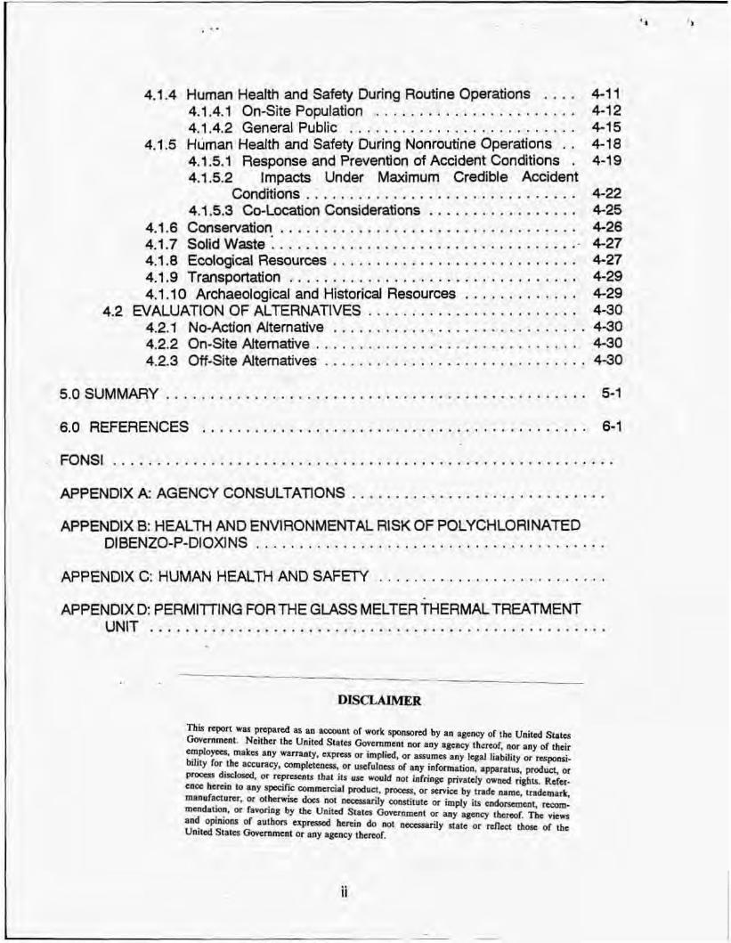
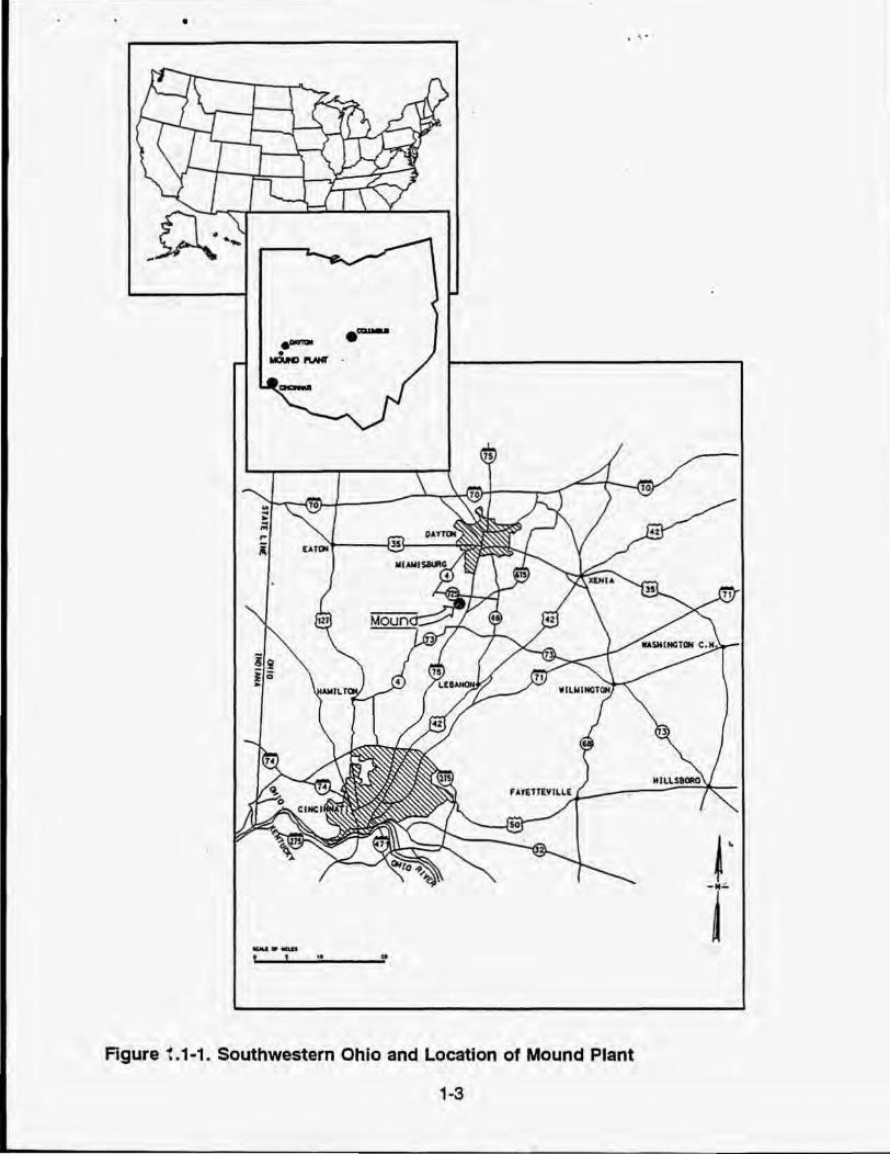
The Mound Plant occupies a 30G-acre site in Montgomery County in southwestern Ohio. The site is located on the southern boundary of the .city of Miamisburg, 16 km (10 mil south-southwest of Dayton, Ohio, and 50 km (31 mil north-northeast of Cincinnati, Ohio, at 39° 37' 42'N, and 84° 17' 15"W (Figure 1.1-1). Mound was previously operated by Monsanto Research Corporation, a subsidiary of the Monsanto Company, for the DOE Albuquerque Operations Office. Since October 1, 1988, the facility has been operated by EG&G Mound Applied Technologies.
In October 1980, at the request of the Low-Level Waste Management Program branch office of DOE, Mound began a study to determine the feasibility of using a glass melter for treatment of low-level radioactive wastes generated at commercial nuclear power facilities (Alexander and Klingler, 1981 ). As a result of this study, the glass melter was put into operation at Mound in early January 1982. Except for a downtime of 24 weeks preparing for radioactive experiments and another downtime of 4 weeks for furnace repair, the melter was in operation or was being maintained at an idle temperature for a period of nearly 3 years. During that time, 2,000 kg (2.2 tons) of materials were successfully processed in the furnace (Klingler and Armstrong, 1985). This evaluation of the glass melter demonstrated that the unit, coupled with an appropriate offgas system, can provide an effective and desirable means of treating low-level radioactive wastes.
The use of the glass melter for treating hazardous wastes was evaluated in later studies. In January 1985, while operating under Resource Conservation and Recovery
1-2
• . , .
. -
_.-f ! - •
Agure 1.1-1. Southwestern Ohio and Location 01 Mound Plant
1-3
f T

---------------------------------------------------------• . ', .
Act (RCRA) Interim Status, a series of experimental bums was conducted in which RCRA Appendix VIII-listed hazardous constituents were included in simulated wastes that were treated in the glass melter. During these experiments, full process monitoring and offgas monitoring were conducted, pursuant to Environmental Protection Agency (EPA) protocol for a trial bum. During these experimental burns, RCRA hazardous organic waste component destruction and removal efficiencies (DREs), as well as hydrogen chloride and particulate removal efficiencies, readily met regulatory requirements for incinerators.
In June 1987, Mound processed other mixtures in the glass melter which simulated the waste streams generated at the Mound Plant explosive powder production facility. Methylene chloride was selected as a principal organiC hazardous constituent (POHC) for these tests. Results again showed that the glass me~er could meet regulatory incinerator standards, including that of destruction of difficult-to-burn hazardous organics, even with highly aqueous waste. Destruction and removal efficiencies and hydrogen chloride removal efficiencies met regulatory standards (Mound, 1987). Following these studies the glass melter was placed in cold shutdown mode at Department of Energy direction pending completion of the NEPA process. It has been maintained in this state since June 1987.
Glass Melter test resu~ effectively demonstrated the util~ of the glass melter in the treatment of both hazardous and low-level radioactive wastes. While the glass melter has never been used to treat mixed wastes, the fact that it has been used successfully to treat both hazardous and low-level radioactive materials indicates that it will also be useful for treatment of mixed wastes.
1_3 THE PROPOSED ACTION
Because of the demonstrated effectiveness of the glass melter, DOE is now considering incorporating this facility into its hazardous and mixed-waste treatment and disposal program for Mound operations. The present document helps meet the National Environmental Policy Act (NEPA) compliance requirements by providing an evaluation of environmental impacts associated with the proposed action (the operation of the glass melter for hazardous and mixed-waste treatment) compared with the no-action alternative (the continuance of existing practices at Mound for the treatment of hazardous and mixed wastes) and other on-site treatment and off-site disposal alternatives.
1-4

2.0 PROPOS,ED ACTION AND ALTERNATIVES
2.1 PROPOSED ACTION
DOE operations at Mound Plant result in the generation of hazardous and radioactive mixed wastes. Haza.rdous wastes are currently being shipped 011 site for treatment and disposal. There are, however, no suitable disposal options for the radioactive mixed wastes, and this material is being stored on site. Since current mixed-waste storage capacity at Mound Plant has been exhausted and present storage of the waste is in violation of RCFlA land disposal restriction regulations, other options for handling this material have been examined. One option available to DOE is to make use of the Mound Plant glass melter. This una has been in cold shutdown mode since June 1987 when the last set of expe,rimentai tests of the unit were completed. Under the proposed action, DOE would bring this unit out of cold shutdown mode and use it for treating both hazardous and mixed wastes generated at Mound Plant The following subsections provide a general engineering description of the proposed action, a detailed characterization of wastes to be processed, and resulting emissions and effluents (source terms).
2.1.1 Engineering Description
The glass melter is designed to destroy hazardous organiC constituents in radioactive mixed waste and haz,ardous waste streams and to convert the waste residue into a form suitable for ultimate disposal. Its proposed operation is intended solely for use in the treatment of wastes generated at Mound Plant. The glass melter unit is housed in an annex of the liquid waste disp'osal (WD) building (Figure 2.1-1) and consists of a burn chamber of stainless steel lined with refractory material (Figure 2.1-2) connected to an ollgas scrub train.
In the proposed operational mode, waste in sealed drums would be transported by truck as needed from either the hazardous waste storage building (Building 72) or the radioactive mixed-waste storage building (Building 23). The drums would be temporarily staged on a concrete pad adjacent to the annex, then moved individually to a fume hood in the WD annex (WDA) so that contents could be transferred into a feed system, ready for processing in the melter. Waste would be transferred to a glass melter feed system either manually or by pumping, depending on the drum's contents.
2-1

Figure 2.1-1. Location of Glass Melter System and Waste Storage Buildings
2·2

o o
,
~ ICII oorSlM
• "R""IC~
Agure 2_1-2_ Schematic of Gla,;s Melter
2-3

During cold startup of the glass melter, soda-lime silica glass cullet (glass manufacturing scrap) is heated in the burn chamber by means of a propane burner. Once the glass has been melted, it is maintained in the molten state by electrode heating. For waste processing, when the melt has reached a temperature of 1,800 - 2,400°F, waste would be introduced into the burn chamber via the feed-port opening on the glass melter roof. Ash from the combustion process falls to the glass surface, where it would be incorporated into the melt When glass chemistry or radioactivity loading dictates, waste glass would be discharged from the melter into 5-gal containers.
The gaseous combustion products exit the furnace and continue on to the offgas wet scrubbing system. Scrubbed gases from the offgas system would be discharged through an existing high efficiency particulate air (HEPA) filter with a removal efficiency of 99.97% (0.3-micron particulates). Scrubbing solution would be filtered, cooled, pH adjusted. and recirculated to the scrubbing equipment. Particulate matter removed by the scrubbing system filter would be pressure backwashed from the filter. The sludge generated would be sampled for hazardous components as required on the basis of waste feed composition and relevant treatment standards, then transferred by pipeline 1) back to a glass melter feed port for reprocessing through the glass melter, 2,. to an existing cementation process for immobilization in concrete, or 3) to container storage for any subsequent additional treatment required by RCRA land disposal restrictions (LOR) .
Filtered liquid effiuent would be characterized as required on the basis of feed composition and treatment standard$. Depending on the components present, it would then be 1) pumped to an existing wastewater treatment facility, 2) pumped to a cementation process for immobilization as concrete, or 3) containerized for subsequent additional treatment as required to meet RCRA land disposal restrictions. For most waste processing it is anticipated that sludge would meet LOR treatment standards and could be land disposed as generated. It is expected that most liquid effluent could be treated at Mound's radioactive wastewater treatment facility and released via an NPOES regulated outfall. Liquid effluent cementation would be required for scrub liquid generated during the processing of waste with significant tritium contamination. Facilities for cementation of both scrubber system residue and triUum contaminated wastewater are currently in use at Mound Plant and would not be significantly impacted by the additional feed from glass melter operations.
By-products of radioactive mixed waste treatment would in some cases also be defined as radioactive mixed waste by application of the RCRA "derived from" rule [45 Fed. Reg. 33096 (May 19, 1980)]. Present planning calls for the shipment of some glass and other solidified by-product waste to a radioactive mixed waste land disposal facility as treatment by-product meeting LOR requirements. Since no land disposal facilities meeting DOE requirements are currently available, it might be necessary to temporarily store this by-product waste on site until suitable facilities are permitted (see Section 2.2.2). Storage of RCRA hazardous waste which has been treated to meet LOR treatment standards. however, would no longer be subject to LOR storage time limitations, and would, in addition, no longer present fire, explosion, or leakage concerns.
2-4

• As an alternative to the need to dispose of certain radioactive mixed waste by
products in a mixed waste landfill, regulations provide the opportunity to petition the EPA to 'delist" the waste, allowing it to be disposed of at a site authorized to accept low-level wastes. Unless the delisting process is modified, however, the process is so cumbersome at present as to be an impractical option. Modifications to the RCRA 'derived from" rule currently under EPA consideration are expected to offer new alternatives for glass melter treatment residue disposal.
Table 2.1-1 summarizes operational conditions which have been selfor the glass melter, based. on past performance experience (Mound, 1987). The glass melter and offgas system process parameters would be monitored on a continuous basis during operation. Waste feed cutoff would be initiated automatically when selected measurements fall outside prescribed ranges. Table 2.1-2 summarizes proposed cutoff limits for the process safeguard system. Final limits would be established as part of the RCRA permitting process. System ventilation is designed to ensure that negative pressures relative to the glass melter room are maintained at all times in the hoppers, furnace chamber, and offgas system.
2.1.2 Source Terms
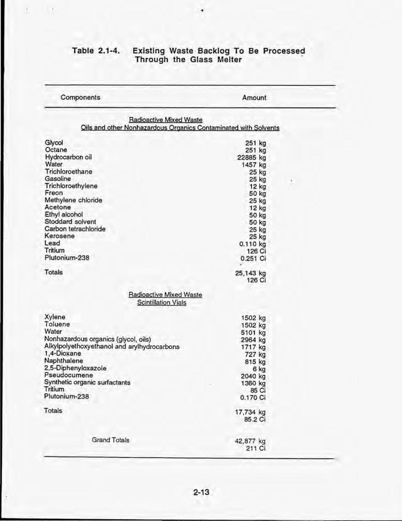
Mound Plant currently generates approximately 39,000 kg/year of mixed wastes and nonradioactive solvent wastes suitable for processing by the glass melter. Table 2.1-3 characterizes these wastes. Mound Plant has an existing backlog of approximately 43,000 kg of mixed wastes (Table 2.1-4). llis Mound Planfs proposal to use the glass melter to process this backlog mixed waste at a rate consistent with . radioactive safety requirements, and to use excess treatment capacity to process suitable newly generated plant wastes. 2 Annual capacity of the glass melter is estimated at 48,000 kg of wastes (based on an average throughput of 23 kg/h, and a 2.080-h work year). On the basis of conservative estimates of backlog waste radioactivity content, and applicable worker safety standards and emission limits. it is anticipated that the backlog can be eliminated within approximately 6 years, while continuing to process new wastes as generated.
Routine operation of the glass melter will result in the generation of treated offgas, caustic scrubber liquid effluent, and several solid waste streams. Mound personnel have generated substantial data characterizing the discharges from glass melter operation. These data are presented in several documents, notably Klingler and Armstrong (1985) and Klingler (1990). Table 2.1-5 summarizes the results of these studies as applied to the proposed operation of the glass melter. The following subsections further characterize the gaseous and solid waste discharges from the glass melter. and the heavy metal and radioactive material content of the discharges.
2 Since this EA was written, DOE has decided to close the Mound Plant. The Glass Melter would, therefore, only be used for backlog waste. The impacts of the new proposed mission would be bounded by the impacts discussed in this EA.
2-5

--- - -----------------------------------------------------------
•
2.1.2.1 Gaseous Emissions
Gaseous emissions (Le., offgas) from the glass melter vary depending on the composition of the wastes being fed to the glass melter. Table 2.1-6 summarizes the results of a series of tests conducted using a range of feed materials characteristic of wastes generated at Mound, as reported by Klingler and Armstrong (1985). This study indicated that for every kilogram of waste processed, the glass melter will generate 10 kg of offgas. These results serve to provide an upper bound on the chemical composition of the oftgas. With respect to particulate matter entering the offgas scrubber system, the highest concentration reported was 2,499 mgIDSm'. Based on observed scrubber removal efficiencies in the range of 61 to 95% (Mound, 1987), the discharge to the HEPA filters will be in the 1,000 to 125 mg/OSm' range. The HEPA filters have a rated efficiency of 99.97% removal for 0.3 micron particulates (Mound, 1987). Assuming an overall efficiency of 99.9%, after the HEPA filter the particulate levels for atmospheric emission will be in the 1.0 to 0.1 mg/OSm' range.
The RCRA Part B Permit Application reports results of a series of test runs conducted to investigate the POHC destruction by the glass melter. Various hazardous waste mixtures (acetonitrile, kerosene, xylene, chlorobenzene, carbon tetrachloride, phenol, and water), wastewater sludges, and solvent wastes (ethylene chloride, acetone, ethanol, and water) were evaluated. OREs were at least 99.999% for all materials tested except for xylene. The averaged xylene OREs ranged from 99.99 to 99.999%. The EPA performance standard for POHCs is >99.99% ORE [40 CFR Part 264.343 (a) (i)l.
The removal efficiencies for gaseous hydrogen chloride (HCI) and other chlorides were also measured during these tests. Minimum removal efficiencies were 99.5% for HCI and 99.9% for chlorides. The EPA performance minimum is 99% for HCI removal [40 CFR Part 264.343 (b)].
2.1.2.2 Solid Wastes
Operation of the glass melter results in four solid waste streams: glass blocks, scrubber sludge, scrubber effluent liquid, and maintenance wastes. The ratio of byproduct generated to waste feed varies greatly as a function of the chemical composition of the waste feed. Data from a study by Klingler and Armstrong (1965) for one waste stream indicated that for every 1,000 kg (1 ,036 L volume for this waste) of waste feed processed, the glass melter will produce 66 kg (26 L) of waste glass block, 16 kg (14 L) of 25% solids sludge, and 750 kg (600 L) of scrubber liquid effluent Based on this data, if 48,000 kg of Mound waste were treated per year, 3,168 kg (1,248 L) of glass, 768 kg (672 L) of 25% solids sludge, and 36,000 kg (28,800 L) of liquid scrubber effluent would be generated. It is anticipated that the glass by-product of the process would meet treatment standards for land disposal for most waste components and be suitable for radioactive disposal in either a Subtitle C or a Subtitle 0 landfill, depending on waste feed composition. Residual sludge from offgas scrUbbing would either be piped back to the glass melter for reprocessing or immobilized by means of a cementation process. It is anticipated that the cement product would meet treatment standards for most feeds, and
2-6
. ,

would be suitable for land disposal in either a Subtitle C or Subtitle D landfill. The cementation process would generate approximately 1,309 kg (923 L) of immobilized sludge.
Scrubber liquid disposition would be dependent on waste radioactivity contamination. It is expected that scrubber liquid generated from the processing of waste contaminated with transuranic isotopes could be effectively treated in Mound's wastewater treatment facility, and then could be subsequently released via an NPDES outfall. Tritiumcontaminated scrubber effluent liquid, however, would require immobilization of the liquid in cement prior to disposal in a radioactive SubtiUe C or SubtiUe D landfill. Based on an assumption that one-half of Mound Plant's radioactive waste contains tritium, and onesixth of this waste would be treated per year, approximately 5,670 kg (4,894 L) of cement immobilized tritium scrub liquid would be generated annually. Residue from treatment of other wastewater would generate apprOximately 1,947 kg (1,681 L) of cement immobilized sludge at the treatment facility. In addition to these process streams, historical data for the offgas system (Klingler, 1981), and projections of glass melter refractory life indicate that routine maintenance of the melter would result in an annual production of 1,926 kg (6,714 L) of maintenance wastes (filters, replacement parts, etc.). Thus, operation of the glass melter at full capacity could be expected to result in an approximated total of 14,020 kg (15,460 L) of wastes. By the RCRA by-product rule, som!, of this by-product waste would potentially be listed as hazardous, and require disposal in a RCRA regulated Subti~e C radioactive landfill. Until such time as a mixed waste disposal facility is available for DOE wastes, RCRA hazardous by-product wastes resulting from the processing of listed mixed wastes would be stored onsite (see section 2.2.2). The immediate value of glass melter treatment for this waste would be its conversion from a form which is primarily liquid and combustible to a safe, stable, inorganic state, which can be stored onsite indefinitely without violation of RCRA land disposal regulations.
Most of the waste generated by glass melter processing would eventually require transportation to a radioactive waste land disposal facility. The projected transport would require one partial shipment (approximately 76 drums) per year. The trip distance would be approximately 2,750 km (1,709 miles) if the waste is shipped to the Nevada Test Site (see subsection 2.2.2.8) .
2.1.2.3 Stack Emissions of Heavy Metals and Radioactivity
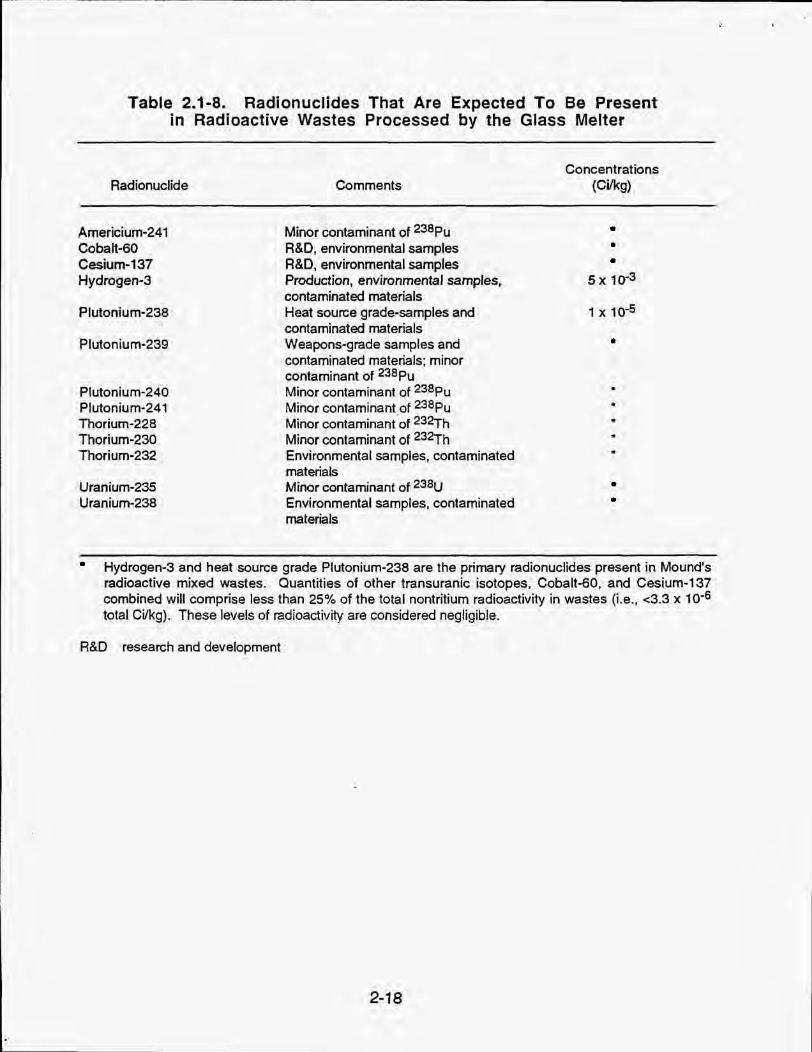
Table 2.1-7 provides data on heavy metals and Table 2.1-8 lists radionuclide species which may be present in wastes processed by the glass melter. Some data are available for certain species whose redistribution was studied in radioactive-waste burning tests (Klingler an~ Armstrong, 1985, 1988). Table 2.1-9 presents data from these experiments. The mass balance boundary for the purposes of these radionuclide distribution runs is at the furnace proper. The offgas was sampled as it left the furnace prior to entering the offgas treatment system. No sampling was done downstream of the offgas treatment system. By comparing metal vaporization temperatures for the four species considered in these tests with those for the species potentially
2-7

present in the waste, some idea of the redistribution of heavy metal and radionuclide species through the glass melter system can be obtained. On this basis, two primary distribution types can be recognized. These are:
Cs distribution type - arsenic, mercury, osmium, cesium, selenium, silver, polonium;
ColMn distribution type - antimony, cadmium, copper, lead, manganese, iridium; and nonvolatile elements as barium, beryllium, chromium, cobalt, nickel, thallium, vanadium, zinc, plutonium, thorium, uranium, actinium, americium, californium, and curium.
Based on these groupings, one can project metal behavior for distoibution throughout the glass melter/offgas system. The heavy metal and radionuclide species distribution should parallel the corresponding results given in Table 2.1-9. The nonvolatile type should follow the ColMn grouping. The unknown vapor-pressure metals would most likely fall in the ColMn grouping. Although not quantifiable with the available data, the result of metal solubility in the sodium hydroxide aqueous offgas spray solution would be to remove metals from the offgas stream.
The potential exists for radionuclide-containinated offgas scrub solution to be entrained in the exiting offgas. In particular, the cesium-type metals would be potentially susceptible to such entrainment. The venturi scrubber system has been shown to have a particulate removal efficiency in the 61 to 95% range (Mound, 1987). Downstream of this scrubber system is a HEPA filter system with 99.97% removal efficiency for 0.3 micron particles. In order to upper bound the otfgas release of metals by entrainment, a worst-ease-condition scenario approach was taken. It was assumed that all of the metal not trapped in the glass or scrub solution would be released to the environment by offgas entrainment. Thus, no credit was given for refractory retention of metals or scrubber system removal of refractory released metals. It was further assumed that the overall HEPA particulate removal efficiency was 99.9% instead of 99.97%. Under this conservative worst-case scenario, the percentage metal stack release to the atmosphere would be:
Cs-type: 0.02%
Co/Mn-type: 0.02%
Thus, downstream of the HEPA system the worst-case level for metals release would be 0.02% of the glass melter waste-feed level.
The tritium ('H) radionuclide component of Mound waste would also leave the glass melter as a gas or vapor. This gaseous species would be effectively captured by the offgas scrub system, but could be re-entrained as water vapor in flue gases. Losses would be relative to scrub liquor concentration and offgas temperatures. Based on a series of test runs using 'H-contaminated dry solid waste (Klingler and Armstrong, 1988),
2-8
'.
the tritium distribution was characterized for the system. Tritium loss to the stack is estimated at 14% of feed (Table 2.1-9).
In light of the waste metal and radioactive constituent levels estimates in Tables 2.1-7 and 2.1-8, the distribution prediCtions provided in Table 2.1-9, the above grouping and assumptions, and a system throughput of approximately 48,000 kg of waste per year (2,080 h/year x 23 kg/h) , release quantities resulting from glass melter operation should not exceed the values provided in Table 2.1-5. It should be noted that the expected waste feed influent 3H and plu1onium-238 (ZI8pu) curies (Ci) per year, based on burning one-sixth of the backlog per year (Table 2.1-4) combined with the annual waste volume (Table 2.1-3), are at the 47 and 0.09 Ci levels, respectively, as compared to the respective upper boundary 240 and 0.5 Ci levels assumed by the Table 2.1-5 approach. Thus, the source terms for 3H and ""Pu in Table 2.1-5 are a factor offive higher than the planned waste inventory burning.
2.1.3 Maximum Credible Accident Scenario
Possible accident scenarios were developed to identify the conditions and the event which would result in the most harmful releases to the environment. The accident with the maximum harmful release is termed the maximum credible accident From an analysis of potential events, the maximum credible accident scenario was determined to be that which would involve the largest accumulation of waste materials, at the location providing the least protection for waste containers. Under planned operation, the only point at which waste will accumulate outside of permitted storage facilities at Buildings 23 and 72 (locations where the wastes are currently stored), is at the staging pad adjacent to WDA. The maximum credible number of waste containers which could be in that location under any foreseeable conditions was selected as ten 55-gallon drums. The accident selected was that of a fire in this drum staging area resu~ing in the complete vaporization of all contents of the ten drums. This accident would result in airbome releases of both radioactive and nonradioactive contaminants. Section 4 .1.5.2 provides a quantitative and qualitative estimate of those releases. The probability of occurrence for this accident is estimated at 0.00001 (Appendix 0).
2-9

Table 2.1-1 . Glass Melter Operational Conditions
Item
CO in Stack Gas
Waste Feed Rate
•
Combustion Zone Temperature
FumaceGas;
Velocity
AowRate
Residence Time
Hel Removal EffICiency
Operational Conditions
<100 ppm
<106 Blulh
1500·2750 of
<50 fps
600 ACFM (max)
>1 .56 sec
>99%
Note: Fugitive emissions and radioactive releases are controlled by negalN's furnace pressure.
2-10

•
Table 2.1-2. Process Safeguard System
Parameter
High CO
Low furnace. chamber: room dP
High furnace, chamber: room dP
Low furnace, chamber temperature (offgas end TC)
High furnace chamber temperature (offgas end TC)
High furnace chamber temperature (feed end TC)
Low scrub pH
Low venturi dP
High venturi dP
High offgas temperature (after spray tank)
High offgas temperature (after ventur~
High liquid feed How
Low liquid feed flow
low flue gas flow rale
dP differential pressure TC thermocouple
Warning
500 ppm peak
7.0
2-11
Warning and Feed Shutdown
1000 ppm peak 100 ppm one hour rolling average
(or equivalent)
0.25 In. water column
6.00 in. water column
26000 F
27500 F
3 .0
25 in. water column
55 in. water column
0.4 gaVmin
0.03 gaVmin
100 ftlmin
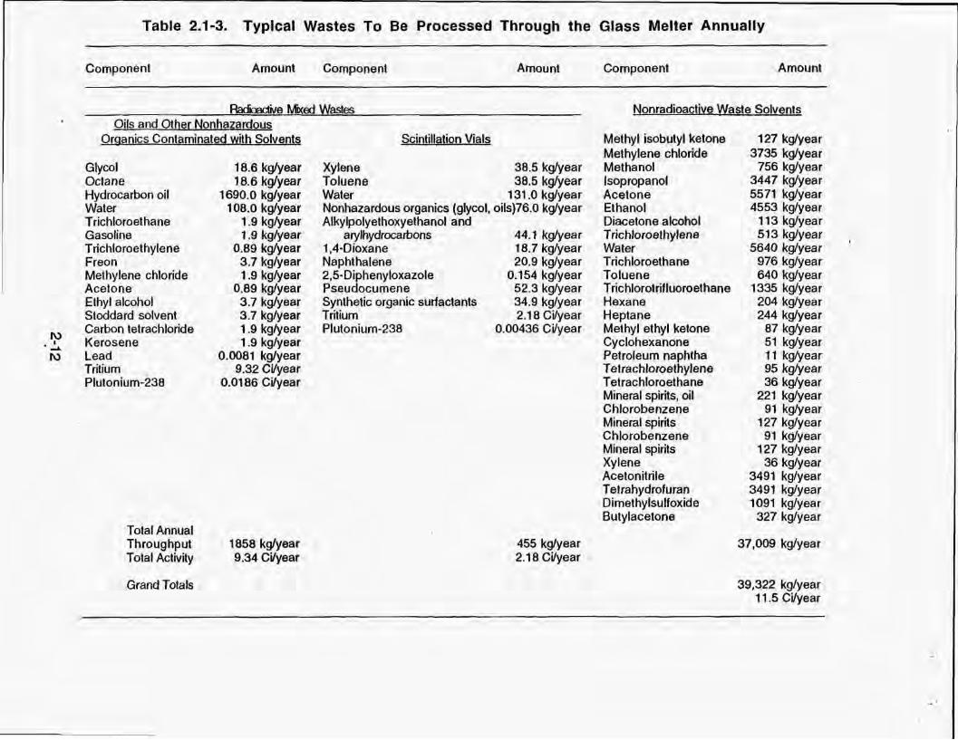
Table 2.1·3. Typical Wastes To Be Processed Through the Glass Melter Annually
Component Amount
Oils and Qther Nonhazardous Organics Contaminated w~h Solvents
Glycol Oclane Hydrocarbon oil Water Trichloroethane Gasoline Trichloroethylene Freon Methylene chloride Acetone Ethyl alcohol Stoddard solvent Carbon tetrachloride Kerosene Lead Trilium PIUlonium-238
T alai Annual Throughput Tolal Activity
Grand T oIals
16.6 kg/year 18.6 kglyeer
1690.0 kg/year 108.0 kg/year
1.9 kglyear 1.9 kglyear
0,89 kg/year 3.7 kglyear 1.9 kglyear
0,89 kg/year 3 .7 kglyear 3 .7 kglyear 1.9 kglyear 1.9 kglyear
0.0081 kg/year 9.32 CVyear
0.0186 CVyear
1856 kg/year 9.34 Cilyear
Component Amount
Scintillation Vials
Xylene 38.5 kglyear Toluene 38.5 kg/year Waler 131.0 kg/year Nonhazardous organics (glycol, oils}76.0 kg/year Alkylpolyelhoxyethanol and
arylhydrocalbons l,4-0ioxane Naphthalene 2,S·Oiphenyloxazole Pseudocumene Synthetic organic surfaclants Tritium Plutonium-238
44.1 kglyear 18.7 kg/year 20.9 kg/year
0.154 kg/year 52.3 kg/year 34.9 kg/year 2.18 CVyear
0.00436 CVyear
455 kg/year 2.18CVyear
Componenl Amount
Nonradioac1jye Waste Solyents
Methyl isobutyl ketone Methylene chloride Methanol Isopropanol Acetone Ethanol Diacetone alcohol T richloroelhylene Water Trichloroethane Toluene Trichlorotrilluoroelhane Hexane Heptane Methyl ethyl ketone Cyclohexanone Petroleum naphtha T elrachloroelhylene Tetrachloroethane Mineral spirits, oil Chlorobenzene Mineral spirits Chlorobenzene Mineral spirits Xylene Acetonitrile T elrahydrofuran Dimethylsulfoxide Butylacetone
127 kg/year 3735 kg/year
756 kwyear 3447 kg/year 5571 kg/year 4553 kg/year
113 kg/y .. r 513 kg'year
5640 kg/year 976 kg/year 640 kglyear
1335 kwyear 204 kglyear 244 kwyear
87 kglyear 51 kwyear 11 kglyear 95 kglyear 36 kg/year
221 kg/year 91 kglyear
127 kg/year 91 kg/year
127 kglyear 36 kg/year
3491 kg/year 3491 kg/year 1091 kg/year
327 kg/year
37,009 kg/year
39,322 kg/year 11.5 CVyear
•
Table 2.1·4. Existing Waste Backlog To Be Processed Through the Glass Meller
Components Amount
Radjoactjye Mixed Waste Oils and other Nonhazardous Qrganics Contamjnated wilh Solvents
Glycol Octane Hydrocarbon oil Water Trichloroethane Gasoline Trichloroethylene Freon Methylene chloride Acetone Ethyl alcohol Stoddard solvent Carbon tetrachloride Kerosene Lead Tritium Plutonium-238
Tolals
Radioactive Mixed Waste Scintillation Vials
Xylene Toluene Water Nonhazardous organics (glycol, oils) Alkylpolyelhoxyelhano[ and arylhydrocarbons , ,4-Dioxane Naphthalene 2.S-0 iphenyloxazole Pseudocumene Synthetic organic surfactants Tritium Plutonium-238
Totals
Grand T otats
2·13
251 kg 251 kg
22885 kg 1457 kg
25 kg 25 kg 12 kg 50 kg 25 kg 12 kg 50 kg 50 kg 25 kg 25 kg
0.110 kg 126 Ci
0.251 Ci
25.143 kg 126 Cj
1502 kg 1502 kg 5101 kg 2964 kg 1717 kg
727 kg 815 kg
6 kg 2040 kg 1360 kg
85 Ci 0.170 Ci
17.734 kg 85.2 Cj
42.sn kg 2" Ci

•
Table 2.1-5 Source Terms
Melter tnfluent Melter Discharge Content
Category Item Content Offgas to Offgas to Aqueous Solid scrubber HEPA
POHC (al <0.1% ~ <0.1%C <0.1%"
HAZARDOUS HCI • •• <0.01 Ib/hr" •• WASTE NO, • •• <100 ppm ' ••
AND CO • •• <1 ppm· •• COMPONENT Unsaturated • •• <1 ppm •• hydrocarbons
OF Particulate • •• <1 mg •• MIXED Aqueous • •• <0.0001%
Discha!ge WASTE Polychlorinated 0.0 SDL SDL •• Cibenzodioxins
pH • •• 8-10
ppm g/year I ~g/L 0
Arsenic 5.0 56 •• 1.8
Cadmium. 2.0 22 •• 0.034
Chromium 10 110 •• 0.17
Lead 100 1100 •• 1.7
Notes:
NA = Not Applicable BOl = Below Detection Umits a = The potential organic hazardous constituent (POHC) composition of the waste feed stream is
given in Tables 2.1-3 and 2.1-4. b = The distribution of inorganic waste h~d constituent in discharge is based on EA Section 2.1.2
assumptions. c = Based on EA section 2.1.2 ORE reslults. d = Based on Table 2.1-1. e = Based on Table 2.1-6. As an upper bound, a value of <1 was assumed for ppm values. f = Based on 99.9% HEPA efficiency . • = Values w ill vary for each drum . •• = Insufficient data collected to characterize .
2-14
NA
NA
NA
NA
NA
NA
NA
NA
ppm o
43
23
120
1200
. ', '

Table 2.1-5 Source Terms (Continued)
Category Item Melter Melter Discharge Content Influent Content Gas Aqueous Solid
CilKg CWea, CiIL Ci/Kg
Americium-241 • - -- --RADIOACTIVE Cobalt·50 • - '- -
Cesium-137 • - ••• -COMPONENT Hydrogen-3 5x10-llV) 3.4x10·' {II.! 7.4x10.J(J\) 0
Plutonium-238 1x10~g} 1.0x10~ 2.4x10·'(~ 1.2x10""
OF MIXED Plutonium-239 • •• --Plutonium-240 • •• .-
WASTE Plutonium-241 • •• _.
Thorium-228 • •• --Thorium-230 • •• .-Thorium-232 • •• .:.
Uranium-235 • •• .-Uranium-23B • - _.
Notes:
9= Sased on Table 2.1-8
h = 5x10'" CilKg x 4.8x10'" Kg burned (max)/year = 240 Cilyear. From Table 2.1-9, 86% in liquid, 14% in gas. 3H content in liquid = 86% x 240 = 206 Ci/year= 20612.8x10'" Uyear = 7.4x10'" Ci/L ]H content in gas = 14% x 240 = 34 Cilyear.
i = Based on Table 2.1-9 and the worst-case approach as discussed in Section 2.1.2.3, the distribution for lJIpu would be 78% in glass Block, 21% in gas, and 1.4% in liquid. 1.0x1005 CVKg x 4.8x10'" Kg waste bumed (max)/year = 0.5 Ci/year. 23&pu in liquid = 1.0x1005 x 4.8x10'" x O.01412.8x10'" = 2.4x10·1. l'38pu in gas = 1.0x1005 x 4.8x10'" x O.21x(1-D.999) = 1 .0x10~ Ci/year .
• = Based on Table 2.1-8, the combined radionuclide content for these nuclides will be <3.3x10'" Ci/Kg .
... = The combined radionuclide release for these nuclides will be <3.3x1005 Ci/year
.- = The combined radionuclide release for these nuclides will be <6.0x10" Ci/year
........ " = The combined radionuclide release for these nuclides will be <4.0x10·5 Cilyear of glass.
2-15
.-.
.-'-'
.--------..-

Table 2.1-6. Summary of Gaseous, Pre-Scrubber Concentrations
AueGas
C02
CO NOx
Unsaturated Hydrocarbons
Combustibles
Concentration
3% 8Vg. (8.3" .. max)
<100 ppm averagea
35 ppm 8Vg. (O.OS% Iblh)b
z~ro ppm C
zero ppm C
Nole: Normal waste feed rate was 23 kgfh and air flow rate was 12 10 415 OSm31h (dry standard cubic meters per hour) .
•
b
c
In a separate series of tests (Mound, 1987). the 4·minute averages of CO levels before the scrubber ranged between 1.4 and 16.8 ppm.
Without dilution air, concentration could be up to 2.8 times higher. but totallblh would be the same.
At standard operating conditions . (Conditions which will be imposed by the Part B pennit.)
2-16

Table 2.1·7. Heavy Metals That Are Expected To Be Present in Wastes Processed by the Glass Melter
Heavy Metal
Arsenic Cadmium Chromium Lead
Source: Weston SelVices, Inc., 1990.
Content· (ppm)
5 2
10 100
* Values are based on EPA not-to-exceed limits for classifying waste oils as nonhazardous.
2·17
.------- -- --- --------------------------------------------------------------------------
Table 2.1-8. Radionuclides That Are Expected To Be Present in Radioactive Wastes Processed by the Glass Melter
Radionuclide
Americium-241 Cobalt-GO Cesium-137 Hydrogen-3
Plutonium-238
Plutonium-239
Plutonium-24Q Plutonium-241 Thorium·228 Thorium-230 Thorium-232
Uranium-235 Uranium-238
Comments
Minor contaminant of 238pu R&D, environmental samples R&D, environmental samples Production, environmental samples. contaminated materials Heat source grade-samples and contaminated materials Weapons-grade samples and contaminated materials: minor contaminant of 238pu Minor contaminant of 238pu Minor contaminant of 238pu Minor contaminant ·of 232Th Minor contaminant of 232Th Environmental samples, contaminated materials Minor contaminant of 238U Environmental samples, contaminated malerials
Concentrations (Cilkg)
• • •
1 x 10⁻⁵
•
• •
• Hydrogen-3 and heat source grade Plutonium-238 are the primary radionucJides present in Mound's radioactive mixed wastes. Quantities of other transuranic isotopes, Cobalt-60, and Cesium-137 combined will comprise less than 25% of the total nontritium radioactivi ty in wastes (i.e., <3.3 x 10⁻⁶
total Ci/kg). These levels of radioactivity are considered negligible.
R&D research and development
2-18

, .
Table 2.1-9. Distr ibution of Radioactive Isotopes in Melter System
% of Total Curies
Scrub Refractory Glass Solution Canyover Uptake"
t37Cs 58b 21 .1d _ .. 20.9"
eDCo 78s ,b l Ac -- 20.6" S4Mn 79b l .4c -- 19.6" 3H 86 14
Sources: Klingler and Armstrong, February 1985.
•
Klingler and Armstrong, first draft 1988.
Based on difference (e.g., 100 - (58 + 21.1) :::: 20.9] By difference definition there is no value for this item
Notes:
a
b
c
d
Spike retention data were used .. Cobalt apparently absorbs rapidly onto the lower floor refractory.
Only runs prior to the electrode replacement were used. There were obvious short-term mixing problems after installation of larger electrodes.
The larger average resuKing from Method 5 sampling was used since the insolubility of the oxide in alkaline scrub solution introduces scrubber sampling errors.
Due to high solubility of cesium in the scrub solution, the scrub solution sample data were selected as the most accurate indicator of furnace loss. The loss is obviously one of continuing vaporization. Only runs prior to the electrode replacement were used.
2-19

2.2 ALTERNATIVES
Mound personnel have reviewed their waste disposal requirements and have consolidated several disposal options. Based on this review, alternatives to the proposed action have been considered. These include both on·site and off-site alternatives. These alternatives are briefly described in the following sections.
2.2.1 On-Site Alternatives
2.2.1.1 No-Action Alternative
The no-action alternative assumes the continuation of present practices of waste storage and disposal. With respect to wastes that would be fed to the glass melter under the proposed action, a total of 143 m' of hazardous waste is presently being shipped off site each year. Currently, these hazardous wastes are being shipped to disposal facilities in Pinewood and Roebuck, South Carolina; Eldorado, Arkansas; and Pecatonica, Illinois.
An additional eight 55-gal drums of mixed waste (approximately 1.6 m', or 56 It'} are curren~y being generated annually and stored on site in Building 23. The storage capacity of Building 23 based on spill capacity has been exhausted. Mound personnel indicate that at the rate mixed wastes are likely to be generated as a result of lab cleanouts and decontamination/decommissioning activity, physical storage capacity will also be exhausted in the near future unless some consolidation of wastes can be accomplished. Since no other storage capacity suitable for these wastes is available on site, adoption of the no-action alternative would require the construction of additional storage capacity. If 55-gal drums have a base diameter of 0.6 m and are stored four to a pallet, stacked two pallets high, then the total annual storage requirement for the mixed wastes is about 1.5 m'. A structure the size of the existing mixed-waste storage building (approximately 23 m', or 247 It~ would provide about 15 years of storage capacity. Under normal Circumstances, a minimum of six years are required to plan, obtain funding, complete safety and environmental studies, and complete such new construction. RCRA pemnitting activity may take additional time.
2.2.1 .2 Administrative Action
The initiation of administrative actions to reduce the generation of radioactive mixed waste provides an alternative for waste control. The Mound Plant has established and formalized a waste minimization and pollution prevention awareness program (EG&G, 1990). A Waste Minimization Committee and Chairman have been selected from members of management. A waste minimization plan (Waste Minimization and Pollution Prevention Awareness Plan, MD·81501) has been developed and issued plant-wide. Training needs have been identified, and a training and communication program has been developed to ensure that all employees understand their obligation to minimize waste generation in all processes and operations.
A program for reviewing all plant processes to fully characterize waste generation and individual waste streams has been put into place at Mound Plant. Technical Manual
2-20
~. .'

MD-81502, 'Process Waste Assessment Plan," specifies activities and methods that will be employed for this program. The primary goal of the program will be to identify, screen, and analyze options to reduce the generation of waste. This program has resulted in the elimination of RCRA hazardous scintillation cocktail waste and a number of solvents, and is expected to significantly reduce all new radioactive mixed waste generation at Mound Plant.
Efforts to reduce waste generation at Mound cannot totally eliminate the generation of radioactive mixed wastes, however. Hazardous waste generating materials are already in radioactive systems, and will eventually become waste. Replacement of some hazardous materials will not be easy to accomplisH under Mound's DOE mission requirements. Waste reduction will not affect waste already in storage. The need for disposal options will persist.
2.2.2 Off-Site Alternatives
All of the following off-site alternatives require transportation from the Mound facility to the designated option site. Transportation of hazardous and radioactive wastes is conducted in compliance with Department of Transportation (001) and state regulations regarding the shipment of such wastes. Annual off-site disposal of approximately 39,000 kg of wastes would require approximately four shipments. These shipments would include three hazardous waste shipments and one mixed-waste Shipment. These materials would be shipped from Mound to one or more of the designated option sites.
The Mound Plant retains a share of the legal responsibility for any environmental problems resulting from transportation, storage, treatment, and land disposal of wastes shipped off-site.
2.2.2.1 Off-Site Hazardous Waste Disposal
Hazardous wastes not contaminated with radioactivity could be shipped off-site for treatment and disposal. Mound currenijy uses the services of Laidlaw Environmental Inc. which is a full service waste treatment company specializing in the disposal of hazardous wastes. This service handles the evaluation, transportation, temporary storage, and disposal (or subcontracting for disposal) of all hazardous wastes, including those not suitable for glass melter treatment Mound currently makes three to five shipments of hazardous waste annually. Laidlaw does not handle mixed wastes, so this disposal option . does not address Mound's primary concern, that of,stored and newly generated mixed wastes.
Use of the Laidlaw option would involve shipment of hazardous wastes to any of several sites used by Laidlaw. Trip distance for these sites ranges from 1,240 km (771 miles) to 3,000 km (1,865 miles). The average distance traveled per trip is 1,100 km (684 miles). This results in an approximate total travel distance of 3,300 km (2,050 miles) for
2-21

the three hazardous waste shipments (of glass melter suitable waste) required to meet Mound Plant's disposal requirements.
2.2.2.2 Quadrex HPS, Inc.
Quadrex HPS, Inc., located in Gainesville, Rorida, is a waste-handling and storage company that can offer the disposal of scintillation fluids and nonradioactive ignitable hazardous wastes. The facility cannot accept non-scintillation mixed wastes, and could accept only those scintillation fluid wastes containing carbon-14, tritium, and other shortlived hospital/research lab type isotopes of concentrations no greater than 0.05 microcuries per gram of medium. Quadrex contracts with waste brokers to transport the various waste components to Gainesville. The liquid scintillation vials are shredded, rinsed, and transported to a sanitary landfill. The fluids are collected, analyzed, and used for fuel in a rotary kiln incineration system. The ignitable hazardous wastes are collected, tested, and used for fuels. The following Mound waste constituents could be burned at the Quadrex facility provided they are components of scintillation fluid which meet the restrictions above, or are not radioactively contaminated:
acetone, carbon disulfide, chlorobenzene, cyclohexanone, ethanol, 1,4-dioxane, hexane, methanol, methyl ethyl ketone, methyl isobutyl ketone, methylene chlOride, naphthalene, tetrachloroethylene, toluene, 1,1,1-trichloroethane, trichloroethylene, and xylene (m,o,p types).
While the Quadrex facility cannot accept non-scintillation mixed wastes, and could accept only a portion of Mound's tritium contaminated scintillation fluid waste, it could accept the three annual shipments of glass melter suitable waste currentiy being sent to the Laidlaw Environmental facilities (Section 2.2.2.1). The Quadrex facility is located approximately 1,450 km (900 miles) from Mound Plant. Transport of the three annual hazardous waste shipments to Quadrex would involve a total annual travel distance of 4,350 km (2,703 miles) .
2-22
2.2.2.3 Diversified Scientific Services, Inc.
Diversified Scientific Services, Inc. (DSSI), located in Kingston, Tennessee, operates an industrial boiler and expects to accept a variety of listed and characteristic RCRA • hazardous wastes as fuel for electricity generation. DSSI has a RCRA pennit for storage of hazardous and radioactive mixed waste. DSSl's radioactive materials license allows it to accept most of the hazardous and radioactive mixed wastes generated and stored at Mound. Treatment of the Mound waste by DSSI, however, may be greaUy restricted by DSSI air penn it conditions, and by impacts of the new Boiler and Industrial Furnace (BIF) regulations. An operating permit issued by the Tennessee Air Pollution Control Board in October, 1990, specifically limits the types of fuel that may be used by DSSI for its boiler to 0001 solvents, natural gas, and liquid propane, and specifically forbids the use of solvents containing halogens or heavy metals. A temporary operating permit issued August, 1991, allowed the addition of F001-FOOS solvents to the fuel lis!, but specifies that it is not a permit to operate. New BIF rules effective August, 1991 require boiler burners to meet the destruction and removal efficiency standards for hazardous waste incinerators. The ability of the DSSI unit to meet those standards and obtain the required BIF license is unknown at this time.
In addition to the permitting unknowns, system capacities are extremely limited at the present time, and the waste acceptance priorities have not been defined. For DSSI and all othe[ commercial facilities, the requirements of DOE Order 5820.2A restricting DOE radioactive waste disposal to DOE facilities must be considered.
2.2.2.4 Idaho National Engineering Laboratory
The Idaho National Engineering Laboratory (I NEL) has a permitted incinerator facility, the Waste Experimental Reduction Facility (WERF), capable of burning low-specific-activity (LSA) radioactive material and hazardous waste. The current waste acceptance criteria (WAC) for WERF prohibit receipt of wastes containing alpha emitters at levels greater than 0.1 nanocuries per gram media, PCBs at levels greater than 50 parts per million, or any free liquids. Waste chloride content must be controlled to limit the chloride release rate to no more than four pounds per hour. These criteria would prohibit the acceptance at WERF of almost all of the waste proposed for treatment in the Glass Melter (Tables 2.1-3 and 2.1-4). The WAC for alpha emittens cannot be increased without substantial upgrades to address safety concerns. The WAC for chlorinated solvents are limited for corrosion protection and cannot be increased without the add~ion of further protective devices to the stack. Finally, the current liquid injection system would also require substantial upgrades to accept free liquids. WERF was shut down in February 1991 to correct potential safety problems. Operation of WERF is contingent on completion of NEPA review and approval of a Safety AnalysiS Report.
2.2.2.5 Los Alamos National Laboratory
The Los Alamos incinerator facility in New Mexico is in the process of being permitted. A RCRA trial burn is currently planned for 1994. The priority for this facility will be the burning of transuranic waste, although some low-level radioactive mixed wastes
2-23
•

generated on site may be treated. Current operational plans do not include acceptance of off-site wastes, and the current LANL RCRA permit prohibits treatment of off-site waste.
• 2.2.2.6 Savannah River Site
The Savannah River Site is currenUy constructing the Consolidated Incinerator Facility (CIF). The CIF will be capable of handling both solid and liquid wastes that are RCRA hazardous, radioactive, or radioactive mixed (including scintillation fluids). DOE is preparing an EIS on waste management at SRS, which will include further analysis of operation of the CIF and other volume reduction alternatives. Trial bums and operation of the CI F are being deferred until the completion of the EI S process. The construction permit from the State of South Carolina, however, does not allow out-of-state waste to be treated in the CIF.
2.2.2.7 Oak Ridge Gaseous Diffusion Plant
The incinerator at the Oak Ridge Gaseous Diffusion Plant (ORGDP) facility in Oak Ridge, Tennessee is currently in use for the disposal of mixed wastes. Priorities for handling waste in this facility are as follows:
1. Use the incinerator for wastes generated within the immediate ORGDP complex.
2. Accept other wastes generated in Oak Ridge.
3. Make the incinerator available for the acceptance of DOE wastes generated in the region.
The ORGDP incinerator has a substantial backlog of wastes that will take several years to destroy. Thus, this alternative would not be available to Mound Plant for several years and will not meet the Mound immediate needs.
2.2.2.8 Nevada Test Site
Disposal of mixed waste at the Nevada Test Site is considered a possible alternative to treatment in the Glass Melter. Land disposal restriction under the Resource Conservation and Recovery Act would require, however, that any mixed waste be treated before disposal. The Nevada Test Site would only, therefore, be a reasonable alternative for Mound waste already treated at another facility. DOE has not yet decided to what extent the Nevada Test Site would be used for future disposal of offsite waste; such decisions will be made after completion of the Environmental Management Programmatic Environmental Impact Statement and the Nevada Test Site Sitewide Environmental Impact Statement.
2-24
" . "