DocLib_1170_Groth 3000 Series Bulletin 700-710
12
3011H cutaway shown Patented US 5,238,021 and 5,931,188 FEATURES • Variable Orifice Sleeve, Field Adjustable • Single Stage Regulation from 200 psig to 0.5" WC • Bubble-Tight Shut-Off • Setting Ranges from 0.5" WC to 15 psig • Modulating Design • Reliability-Tested to 5,000 Cycles • Simple Operation, Spring-Loaded "Push-Push" Balanced Piston Design • Low Maintenance Cost SERIES 3000 BLANKET GAS REGULATORS
-
Upload
sergio-andres-rivera-jaramillo -
Category
Documents
-
view
243 -
download
1
description
manual
Transcript of DocLib_1170_Groth 3000 Series Bulletin 700-710
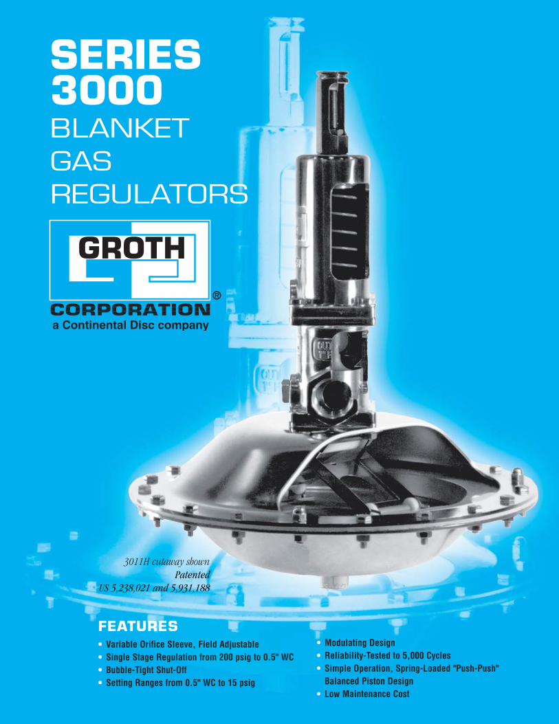
3011H cutaway shownPatented
US 5,238,021 and 5,931,188
FEATURES• Variable Orifice Sleeve, Field Adjustable• Single Stage Regulation from 200 psig to 0.5" WC• Bubble-Tight Shut-Off• Setting Ranges from 0.5" WC to 15 psig
• Modulating Design• Reliability-Tested to 5,000 Cycles• Simple Operation, Spring-Loaded "Push-Push"
Balanced Piston Design• Low Maintenance Cost
SERIES3000BLANKETGASREGULATORS
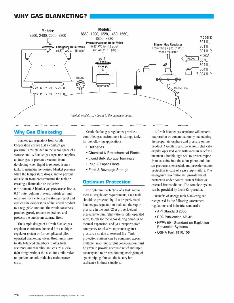
Why Gas Blanketing
Blanket gas regulators from GrothCorporation ensure that a constant gaspressure is maintained in the vapor space of astorage tank. A blanket gas regulator suppliesan inert gas to prevent a vacuum fromdeveloping when liquid is removed from atank, to maintain the desired blanket pressurewhen the temperature drops, and to preventoutside air from contaminating the tank orcreating a flammable or explosiveenvironment. A blanket gas pressure as low as0.5" water column prevents outside air andmoisture from entering the storage vessel andreduces the evaporation of the stored productto a negligible amount. The result conservesproduct, greatly reduces emissions, andprotects the tank from external fires.
The simple design of a Groth blanket gasregulator eliminates the need for a multipleregulator system or for complicated pilotoperated blanketing valves. Groth units havetotally balanced chambers to offer highaccuracy and reliability, and ensure a leak-tight design without the need for a pilot valveto operate the unit, reducing maintenancecosts.
Groth blanket gas regulators provide acontrolled gas environment in storage tanksfor the following applications:
• Refineries
• Chemical & Petrochemical Plants
• Liquid Bulk Storage Terminals
• Pulp & Paper Plants
• Food & Beverage Storage
Optimum Protection
For optimum protection of a tank and tomeet all regulatory requirements, each tankshould be protected by 1) a properly-sizedblanket gas regulator, to maintain the vaporpressure in the tank, 2) a properly-sizedpressure/vacuum relief valve or pilot operatedvalve, to release the vapor during pump-in orthermal expansion, and 3) a properly-sizedemergency relief valve to protect againstpressure rise due to external fire. Tankprotection systems can be combined acrossmultiple tanks, but careful consideration mustbe given to provide adequate relief and inputcapacity and to prevent fouling or clogging ofsystem piping. Consult the factory forassistance in these situations.
A Groth blanket gas regulator will preventevaporation or contamination by maintainingthe proper atmosphere and pressure on theproduct. A Groth pressure/vacuum relief valveor pilot operated valve with vacuum relief willmaintain a bubble-tight seal to prevent vaporfrom escaping into the atmosphere until theset pressure is exceeded, and provide vacuumprotection in case of a gas supply failure. Theemergency relief valve will provide vesselprotection under control system failure orexternal fire conditions. The complete systemcan be provided by Groth Corporation.
Benefits of storage tank blanketing arerecognized by the following governmentregulations and industrial standards:
• API Standard 2000
• EPA Publication AP-42
• NFPA 69 - Standard on ExplosionPrevention Systems
• OSHA Part 1910.106
700 Groth Corporation, a Continental Disc company, Stafford, TX, USA
Models:2500, 2400, 2000, 2300
Models:8860, 1200, 1220, 1460, 1660,
8800, 8820Pressure/Vacuum Relief Valve
0.87" WC to +15 psig/-.87" WC to -12 psig*
Models:3011L,3011H,3011HP,3020A,3070,3041L,3041H,3041HP
WHY GAS BLANKETING?
Emergency Relief Valve+0.87” WC to +15 psig*
Blanket Gas RegulatorFrom 200 psig to .5" WC*
w/one regulator
* Not all models may be set to the complete range.
Features
Groth gas blanket regulators have thefollowing features:
• Direct acting, modulating valves witha patented force multiplying linkage(not used in 3011HP, 3041HP, or3020A models)
• Balanced forces acting on piston(setting is not affected by supplypressure)
• Compact size and weight
• Setting range is from –10 psig to+15 psig (Consult the factory forother settings)
• Molded Teflon® 1 (FEP) ActuatorDiaphragm
• NPT or flange connections
• Wide selection of elastomer sealmaterials
• Field adjustable flow capacity(5%-100%)
• Remote installation configurationavailable
• Available for vacuum service
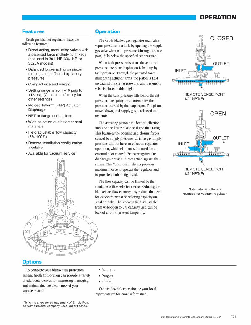
Operation
The Groth blanket gas regulator maintainsvapor pressure in a tank by opening the supplygas valve when tank pressure (through a senseport) falls below the specified set pressure.
When tank pressure is at or above the setpressure, the plate diaphragm is held up bytank pressure. Through the patented force-multiplying actuator arms, the piston is held up against the spring pressure, and the supplyvalve is closed bubble-tight.
When the tank pressure falls below the setpressure, the spring force overcomes thepressure exerted by the diaphragm. The pistonmoves down, and supply gas is released intothe tank.
The actuating piston has identical effectiveareas on the lower piston seal and the O-ring.This balances the opening and closing forcescaused by supply pressure; variable gas supplypressure will not have an effect on regulatoroperation, which eliminates the need for anexternal pilot control. Pressure against thediaphragm provides direct action against thespring. This “push-push” design providesmaximum force to operate the regulator and to provide a bubble-tight seal.
The flow capacity can be limited by therotatable orifice selector sleeve. Reducing theblanket gas flow capacity may reduce the needfor excessive pressure relieving capacity onsmaller tanks. The sleeve is field adjustablefrom wide-open to 5% capacity, and can belocked down to prevent tampering.
Groth Corporation, a Continental Disc company, Stafford, TX, USA 701
OPERATION
Options
To complete your blanket gas protectionsystem, Groth Corporation can provide a varietyof additional devices for measuring, managing,and maintaining the cleanliness of your storage system:
• Gauges
• Purges
• Filters
Contact Groth Corporation or your localrepresentative for more information.
Note: Inlet & outlet arereversed for vacuum regulator.
1 Teflon is a registered trademark of E.I. du Pontde Nemours and Company used under license.
REMOTE SENSE PORT1/2" NPT(F)
REMOTE SENSE PORT1/2" NPT(F)
702 Groth Corporation, a Continental Disc company, Stafford, TX, USA
PISTON DETAIL
TOP VIEW
31
37
38
39
12
40
14
41 8
8
6
7
29 30
37
31 31a
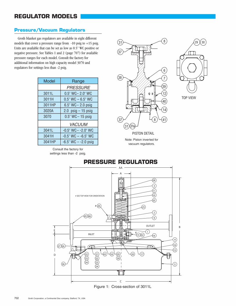
Figure 1: Cross-section of 3011L
Pressure/Vacuum Regulators
Groth blanket gas regulators are available in eight differentmodels that cover a pressure range from -10 psig to +15 psig.Units are available that can be set as low as 0.5" WC positive ornegative pressure. See Tables 1 and 2 (page 707) for availablepressure ranges for each model. Consult the factory foradditional information on high capacity model 3070 andregulators for settings less than -2 psig.
Model Range
PRESSURE3011L 0.5" WC– 2.0" WC3011H 0.5" WC – 6.5" WC3011HP 6.5" WC– 2.0 psig3020A 2.0 psig – 15 psig3070 0.5" WC– 15 psig
VACUUM3041L -0.5" WC– -2.0" WC3041H -0.5" WC – -6.5" WC3041HP -6.5" WC – -2.0 psig
REGULATOR MODELS
Consult the factory forsettings less than -2 psig.
Note: Piston inverted forvacuum regulators.
PRESSURE REGULATORS
14.00
A
1.63
8.38
19.38 +_
INLET
OUTLET
#
# SEE TOP VIEW FOR ORIENTATION
1/2" FNPT REMOTE SENSE PORT
#
2
42 13
1
26
21
46 45 9
10
35
25
28
11
3
19 4
36
16
32
33
34
17 20 23
22
24 29
30
18 43
15
5
26 2727.1
3.75
39
12
40
14
418
2
6
7
4213
1
26
9
10
35
25
28
11
3
415
5
26 27
36
32
33
34
Ø14.00
29
20
17.88
INLET
OUTLET
6.88
1.63
4645
Ø13.00 ±.25
TOP VIEW
#
#
1/2" FNPT REMOTESENSE PORT
27.116 17 18
19
43
REGULATOR MODELS
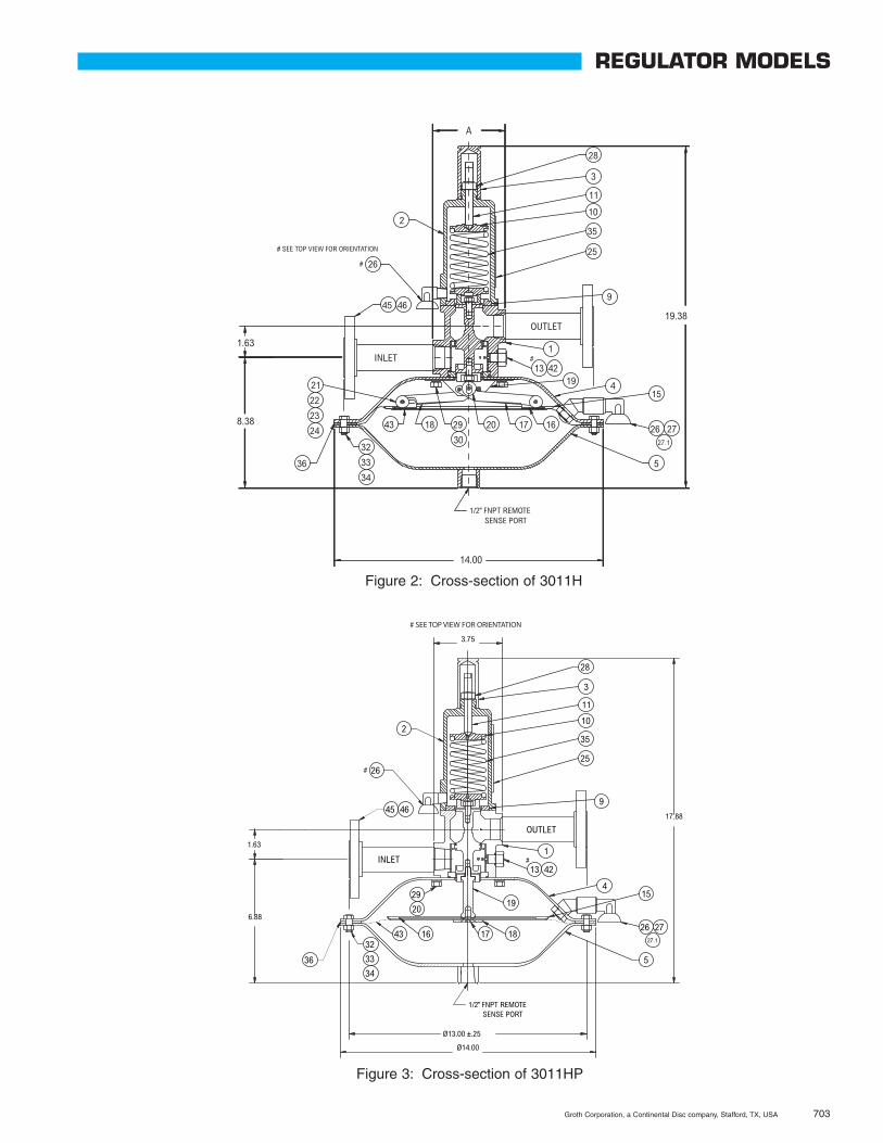
Figure 3: Cross-section of 3011HP
Groth Corporation, a Continental Disc company, Stafford, TX, USA 703
Figure 2: Cross-section of 3011H
704 Groth Corporation, a Continental Disc company, Stafford, TX, USA
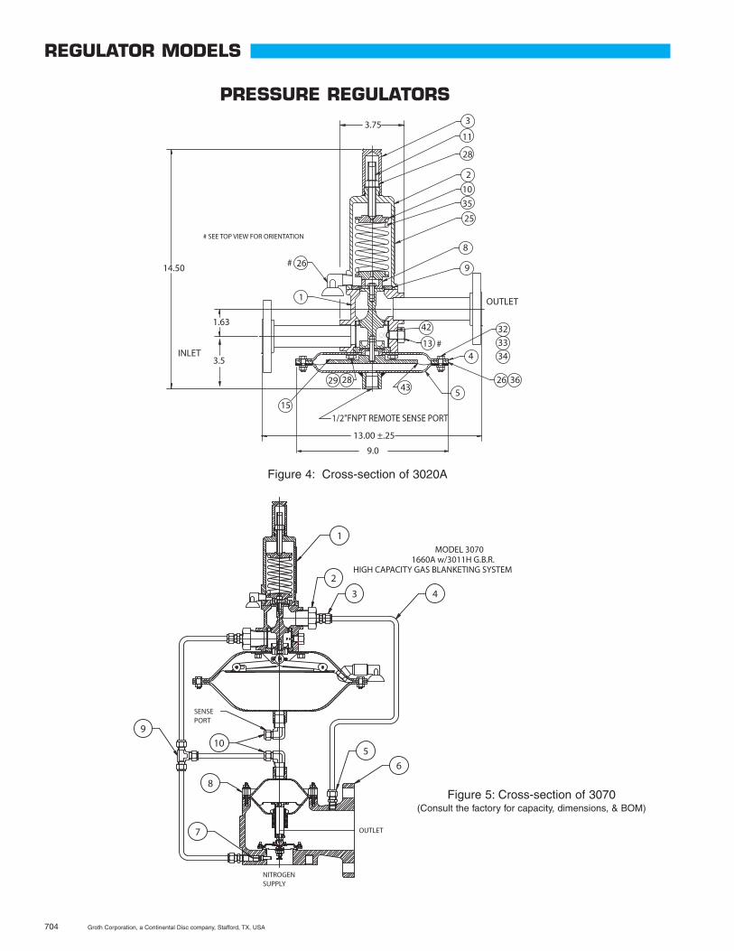
Figure 4: Cross-section of 3020A
Figure 5: Cross-section of 3070(Consult the factory for capacity, dimensions, & BOM)
REGULATOR MODELS
PRESSURE REGULATORS
Groth Corporation, a Continental Disc company, Stafford, TX, USA 705
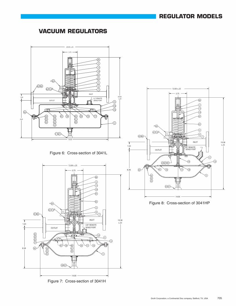
Figure 6: Cross-section of 3041L
Figure 7: Cross-section of 3041H
Figure 8: Cross-section of 3041HP
REGULATOR MODELS
VACUUM REGULATORS
706 Groth Corporation, a Continental Disc company, Stafford, TX, USA
COMPONENT LIST
3011
L
3011
H
3011
HP
3020
A
3041
L
3041
H
3041
HPBILL OF MATERIALS
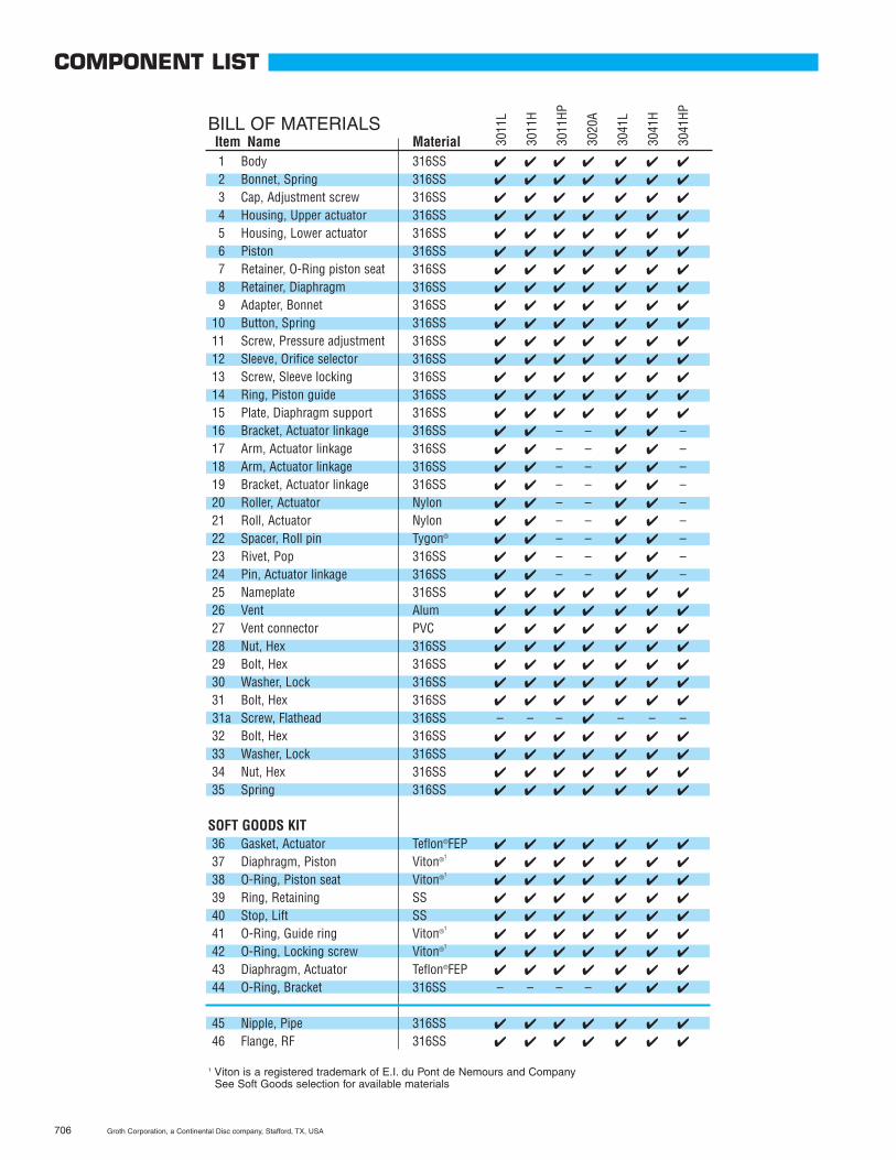
1 Body 316SS � � � � � � �
2 Bonnet, Spring 316SS � � � � � � �
3 Cap, Adjustment screw 316SS � � � � � � �
4 Housing, Upper actuator 316SS � � � � � � �
5 Housing, Lower actuator 316SS � � � � � � �
6 Piston 316SS � � � � � � �
7 Retainer, O-Ring piston seat 316SS � � � � � � �
8 Retainer, Diaphragm 316SS � � � � � � �
9 Adapter, Bonnet 316SS � � � � � � �
10 Button, Spring 316SS � � � � � � �
11 Screw, Pressure adjustment 316SS � � � � � � �
12 Sleeve, Orifice selector 316SS � � � � � � �
13 Screw, Sleeve locking 316SS � � � � � � �
14 Ring, Piston guide 316SS � � � � � � �
15 Plate, Diaphragm support 316SS � � � � � � �
16 Bracket, Actuator linkage 316SS � � – – � � –17 Arm, Actuator linkage 316SS � � – – � � –18 Arm, Actuator linkage 316SS � � – – � � –19 Bracket, Actuator linkage 316SS � � – – � � –20 Roller, Actuator Nylon � � – – � � –21 Roll, Actuator Nylon � � – – � � –22 Spacer, Roll pin Tygon® � � – – � � –23 Rivet, Pop 316SS � � – – � � –24 Pin, Actuator linkage 316SS � � – – � � –25 Nameplate 316SS � � � � � � �
26 Vent Alum � � � � � � �
27 Vent connector PVC � � � � � � �
28 Nut, Hex 316SS � � � � � � �
29 Bolt, Hex 316SS � � � � � � �
30 Washer, Lock 316SS � � � � � � �
31 Bolt, Hex 316SS � � � � � � �
31a Screw, Flathead 316SS – – – � – – –32 Bolt, Hex 316SS � � � � � � �
33 Washer, Lock 316SS � � � � � � �
34 Nut, Hex 316SS � � � � � � �
35 Spring 316SS � � � � � � �
SOFT GOODS KIT36 Gasket, Actuator Teflon®FEP � � � � � � �
37 Diaphragm, Piston Viton®1� � � � � � �
38 O-Ring, Piston seat Viton®1� � � � � � �
39 Ring, Retaining SS � � � � � � �
40 Stop, Lift SS � � � � � � �
41 O-Ring, Guide ring Viton®1� � � � � � �
42 O-Ring, Locking screw Viton®1� � � � � � �
43 Diaphragm, Actuator Teflon®FEP � � � � � � �
44 O-Ring, Bracket 316SS – – – – � � �
45 Nipple, Pipe 316SS � � � � � � �
46 Flange, RF 316SS � � � � � � �
1 Viton is a registered trademark of E.I. du Pont de Nemours and CompanySee Soft Goods selection for available materials
Item Name Material
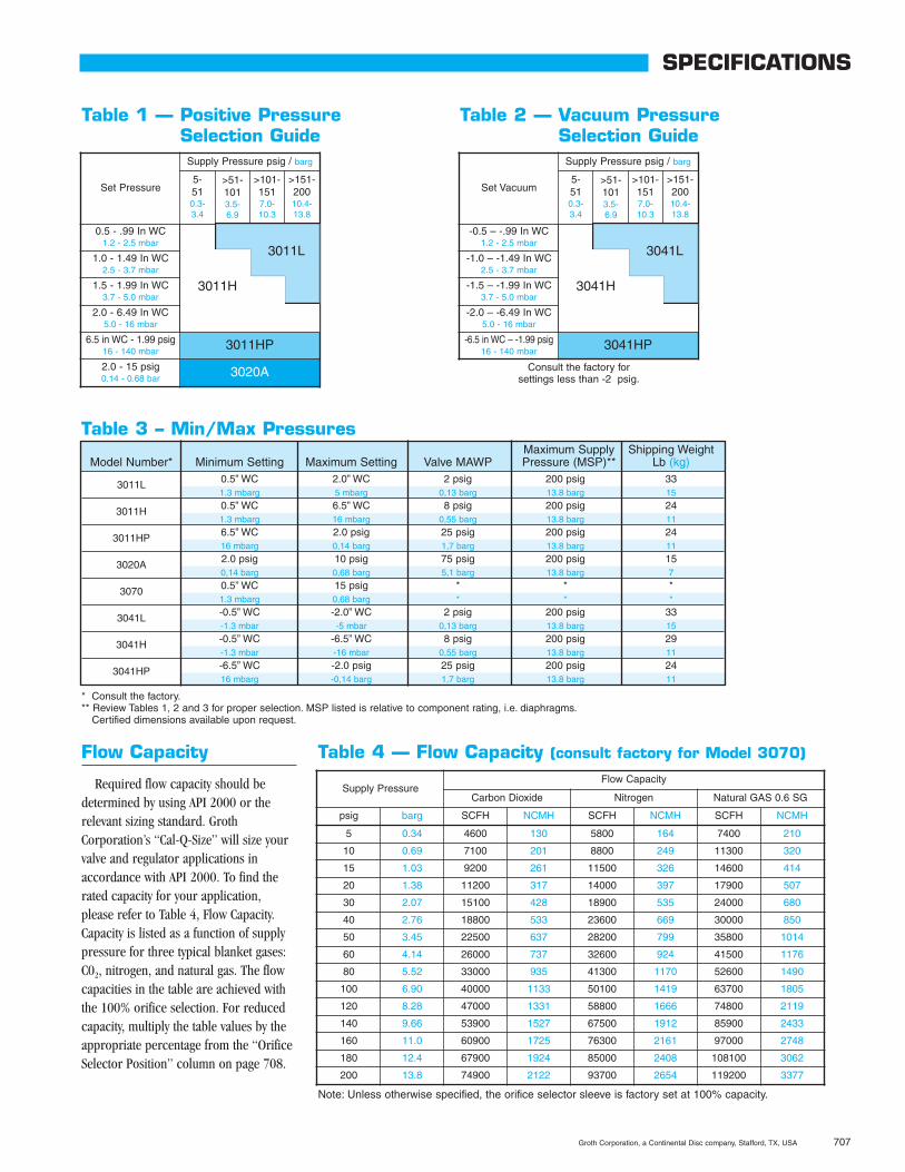
Table 1 — Positive PressureSelection Guide
Supply PressureFlow Capacity
Carbon Dioxide Nitrogen Natural GAS 0.6 SG
psig barg SCFH NCMH SCFH NCMH SCFH NCMH
5 0.34 4600 130 5800 164 7400 210
10 0.69 7100 201 8800 249 11300 320
15 1.03 9200 261 11500 326 14600 414
20 1.38 11200 317 14000 397 17900 507
30 2.07 15100 428 18900 535 24000 680
40 2.76 18800 533 23600 669 30000 850
50 3.45 22500 637 28200 799 35800 1014
60 4.14 26000 737 32600 924 41500 1176
80 5.52 33000 935 41300 1170 52600 1490
100 6.90 40000 1133 50100 1419 63700 1805
120 8.28 47000 1331 58800 1666 74800 2119
140 9.66 53900 1527 67500 1912 85900 2433
160 11.0 60900 1725 76300 2161 97000 2748
180 12.4 67900 1924 85000 2408 108100 3062
200 13.8 74900 2122 93700 2654 119200 3377
Note: Unless otherwise specified, the orifice selector sleeve is factory set at 100% capacity.
Flow Capacity
Required flow capacity should bedetermined by using API 2000 or therelevant sizing standard. GrothCorporation’s “Cal-Q-Size” will size yourvalve and regulator applications inaccordance with API 2000. To find therated capacity for your application,please refer to Table 4, Flow Capacity.Capacity is listed as a function of supplypressure for three typical blanket gases:C02, nitrogen, and natural gas. The flowcapacities in the table are achieved withthe 100% orifice selection. For reducedcapacity, multiply the table values by theappropriate percentage from the “OrificeSelector Position” column on page 708.
Set Pressure
Supply Pressure psig / barg
0.5 - .99 In WC1.2 - 2.5 mbar
1.0 - 1.49 In WC2.5 - 3.7 mbar
1.5 - 1.99 In WC3.7 - 5.0 mbar
2.0 - 6.49 In WC5.0 - 16 mbar
6.5 in WC - 1.99 psig16 - 140 mbar 3011HP
2.0 - 15 psig0.14 - 0.68 bar 3020A
Table 4 — Flow Capacity (consult factory for Model 3070)
3011H
3011L
>151-20010.4-13.8
>101-1517.0-10.3
>51-1013.5-6.9
5-510.3-3.4
Groth Corporation, a Continental Disc company, Stafford, TX, USA 707
SPECIFICATIONS
* Consult the factory.** Review Tables 1, 2 and 3 for proper selection. MSP listed is relative to component rating, i.e. diaphragms.
Certified dimensions available upon request.
Table 3 – Min/Max PressuresMaximum Supply Shipping Weight
Model Number* Minimum Setting Maximum Setting Valve MAWP Pressure (MSP)** Lb (kg)
3011L 0.5” WC 2.0” WC 2 psig 200 psig 331.3 mbarg 5 mbarg 0,13 barg 13.8 barg 15
3011H 0.5” WC 6.5” WC 8 psig 200 psig 241.3 mbarg 16 mbarg 0,55 barg 13.8 barg 11
3011HP 6.5” WC 2.0 psig 25 psig 200 psig 2416 mbarg 0,14 barg 1,7 barg 13.8 barg 11
3020A 2.0 psig 10 psig 75 psig 200 psig 150,14 barg 0,68 barg 5,1 barg 13.8 barg 7
3070 0.5” WC 15 psig * * *1.3 mbarg 0,68 barg * * *
3041L -0.5” WC -2.0” WC 2 psig 200 psig 33-1.3 mbar -5 mbar 0,13 barg 13.8 barg 15
3041H -0.5” WC -6.5” WC 8 psig 200 psig 29-1.3 mbar -16 mbar 0,55 barg 13.8 barg 11
3041HP -6.5” WC -2.0 psig 25 psig 200 psig 2416 mbarg -0,14 barg 1,7 barg 13.8 barg 11
Table 2 — Vacuum PressureSelection Guide
Set Vacuum
Supply Pressure psig / barg
-0.5 – -.99 In WC1.2 - 2.5 mbar
-1.0 – -1.49 In WC2.5 - 3.7 mbar
-1.5 – -1.99 In WC3.7 - 5.0 mbar
-2.0 – -6.49 In WC5.0 - 16 mbar
-6.5 in WC – -1.99 psig16 - 140 mbar 3041HP
3041H
3041L
>151-20010.4-13.8
>101-1517.0-10.3
>51-1013.5-6.9
5-510.3-3.4
Consult the factory forsettings less than -2 psig.
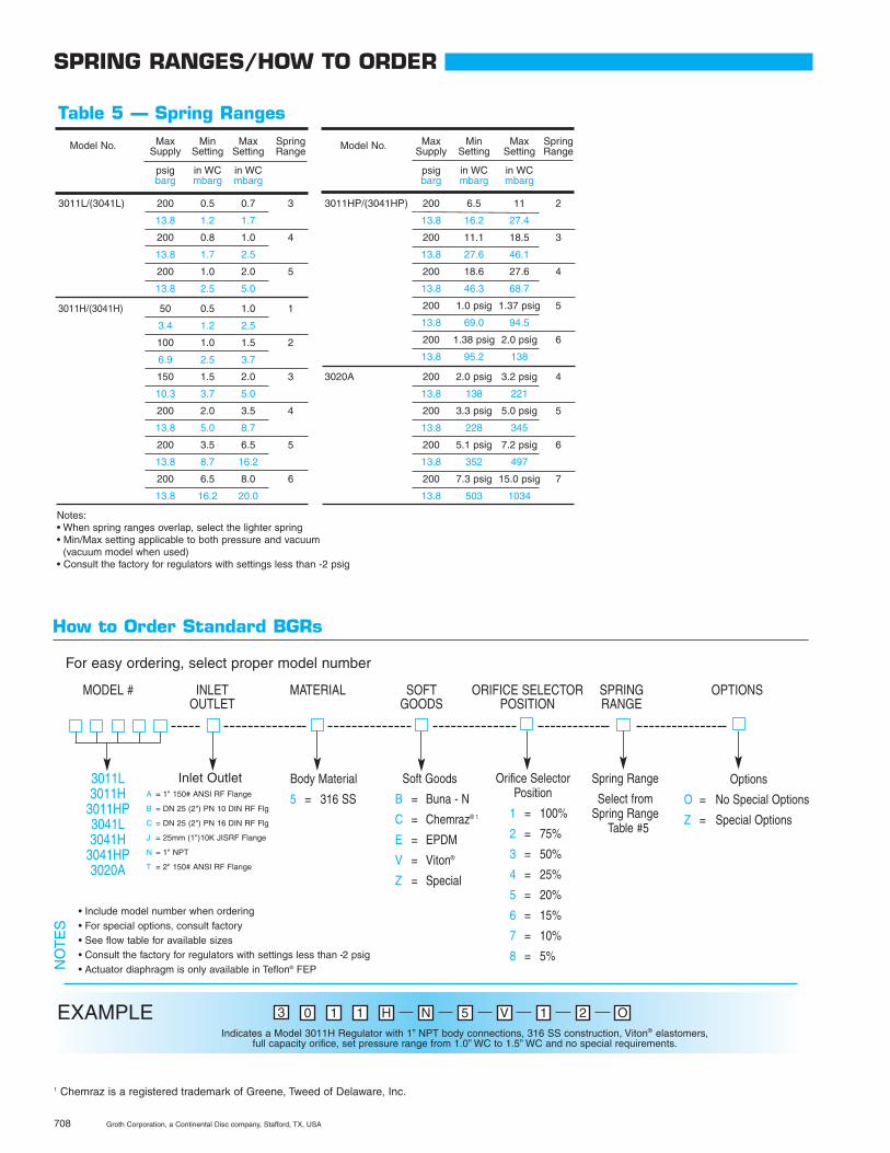
0 1 1 H NEXAMPLE
MODEL # INLET MATERIAL SOFT ORIFICE SELECTOR SPRING OPTIONSOUTLET GOODS POSITION RANGE
3011L3011H
3011HP3041L3041H
3041HP3020A
Inlet OutletA = 1" 150# ANSI RF Flange
B = DN 25 (2") PN 10 DIN RF Flg
C = DN 25 (2") PN 16 DIN RF Flg
J = 25mm (1")10K JISRF Flange
N = 1" NPT
T = 2" 150# ANSI RF Flange
• Include model number when ordering• For special options, consult factory• See flow table for available sizes• Consult the factory for regulators with settings less than -2 psig• Actuator diaphragm is only available in Teflon® FEPN
OT
ES
For easy ordering, select proper model number
Body Material
5 = 316 SS
Soft Goods
B = Buna - N
C = Chemraz® 1
E = EPDM
V = Viton®
Z = Special
Orifice SelectorPosition
1 = 100%
2 = 75%
3 = 50%
4 = 25%
5 = 20%
6 = 15%
7 = 10%
8 = 5%
Spring Range
Select fromSpring Range
Table #5
Options
O = No Special Options
Z = Special Options
Indicates a Model 3011H Regulator with 1” NPT body connections, 316 SS construction, Viton® elastomers,full capacity orifice, set pressure range from 1.0” WC to 1.5” WC and no special requirements.
5 V 1 2 O3
SPRING RANGES/HOW TO ORDER
How to Order Standard BGRs
708 Groth Corporation, a Continental Disc company, Stafford, TX, USA
Notes:• When spring ranges overlap, select the lighter spring• Min/Max setting applicable to both pressure and vacuum
(vacuum model when used)• Consult the factory for regulators with settings less than -2 psig
Model No. Max Min Max SpringSupply Setting Setting Range
psig in WC in WCbarg mbarg mbarg
3011L/(3041L) 200 0.5 0.7 3
13.8 1.2 1.7
200 0.8 1.0 4
13.8 1.7 2.5
200 1.0 2.0 5
13.8 2.5 5.0
3011H/(3041H) 50 0.5 1.0 1
3.4 1.2 2.5
100 1.0 1.5 2
6.9 2.5 3.7
150 1.5 2.0 3
10.3 3.7 5.0
200 2.0 3.5 4
13.8 5.0 8.7
200 3.5 6.5 5
13.8 8.7 16.2
200 6.5 8.0 6
13.8 16.2 20.0
Table 5 — Spring Ranges
Model No. Max Min Max SpringSupply Setting Setting Range
psig in WC in WCbarg mbarg mbarg
3011HP/(3041HP) 200 6.5 11 2
13.8 16.2 27.4
200 11.1 18.5 3
13.8 27.6 46.1
200 18.6 27.6 4
13.8 46.3 68.7
200 1.0 psig 1.37 psig 5
13.8 69.0 94.5
200 1.38 psig 2.0 psig 6
13.8 95.2 138
3020A 200 2.0 psig 3.2 psig 4
13.8 138 221
200 3.3 psig 5.0 psig 5
13.8 228 345
200 5.1 psig 7.2 psig 6
13.8 352 497
200 7.3 psig 15.0 psig 7
13.8 503 1034
1 Chemraz is a registered trademark of Greene, Tweed of Delaware, Inc.
Groth Corporation, a Continental Disc company, Stafford, TX, USA 709
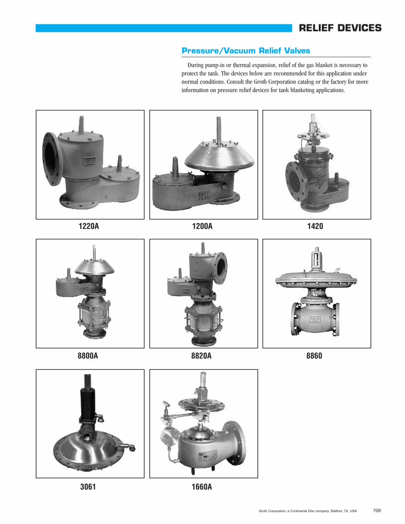
RELIEF DEVICES
Pressure/Vacuum Relief Valves
During pump-in or thermal expansion, relief of the gas blanket is necessary toprotect the tank. The devices below are recommended for this application undernormal conditions. Consult the Groth Corporation catalog or the factory for moreinformation on pressure relief devices for tank blanketing applications.
1220A 1200A 1420
8800A 8820A 8860
3061 1660A
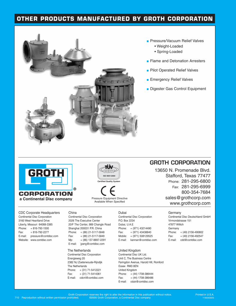
Pressure/Vacuum Relief Valves• Weight-Loaded• Spring-Loaded
Flame and Detonation Arresters
Pilot Operated Relief Valves
Emergency Relief Valves
Digester Gas Control Equipment
GROTH CORPORATION13650 N. Promenade Blvd.
Stafford, Texas 77477Phone: 281-295-6800
Fax: 281-295-6999800-354-7684
Groth Corporation reserves the right to alter the information in this publication without notice. Printed in U.S.A.710 Reproduction without written permission prohibited. ©2006 Groth Corporation, a Continental Disc company 11063500DG
CDC Corporate HeadquartersContinental Disc Corporation3160 West Heartland DriveLiberty, Missouri 64068-3385Phone: + 816-792-1500Fax: + 816-792-2277E-mail: [email protected]: www.contdisc.com
ChinaContinental Disc Corporation2026 The Executive Center20/F The Center, 989 Changle RoadShanghai 200031 P.R. ChinaPhone: + (86) 21-5117-5848Fax: + (86) 21-5117-5849Mp: + (86) 137-8897-2291E-mail: [email protected]
DubaiContinental Disc CorporationP.O. Box 2234Dubai, U.A.EPhone: + (971) 43214490Fax: + (971) 43438840Mobile: + (971) 508129525E-mail: [email protected]
GermanyContinental Disc Deutschland GmbHVirmondstrasse 15147877 WillichGermanyPhone: + (49) 2156-490802Fax: + (49) 2156-492547E-mail: [email protected]
Pressure Equipment DirectiveAvailable When Specified
OTHER PRODUCTS MANUFACTURED BY GROTH CORPORATION
The NetherlandsContinental Disc CorporationEnergieweg 202382 NJ Zoeterwoude-RijndijkThe NetherlandsPhone: + (31) 71-5412221Fax: + (31) 71-5414361E-mail: [email protected]
United KingdomContinental Disc UK Ltd.Unit C, The Business CentreFaringdon Avenue, Harold Hill, RomfordEssex RM3 8ENUnited KingdomPhone: + (44) 1708-386444Fax: + (44) 1708-386486E-mail: [email protected]