Doc.: IEEE 802.15- Submission Some Challenges for Visible Light Communications Dominic O’Brien...
25
doc.: IEEE 802.15- <doc#> Submiss ion Some Challenges for Visible Light Communications Dominic O’Brien Lubin Zeng Hoa Le Minh Grahame Faulkner Department of Engineering Science, University of Oxford
-
Upload
raymond-mccarthy -
Category
Documents
-
view
214 -
download
0
Transcript of Doc.: IEEE 802.15- Submission Some Challenges for Visible Light Communications Dominic O’Brien...
doc.: IEEE 802.15-<doc#>
Submission
Some Challenges for Visible Light Communications
Dominic O’BrienLubin ZengHoa Le MinhGrahame FaulknerDepartment of Engineering Science, University of Oxford
doc.: IEEE 802.15-<doc#>
Submission
Introduction
• Typical VLC link characteristics• Challenges
– Technical• Bandwidth limitations• Providing an uplink
– Regulatory• Compatibility with Lighting Control systems• Illumination systems
• Conclusions
doc.: IEEE 802.15-<doc#>
Submission
Typical link characteristics
• Source
• Channel
• Receiver

doc.: IEEE 802.15-<doc#>
Submission
LED Modulation
• Opto-electronic response
0 10 20 30 40 50-25
-20
-15
-10
-5
0
freq ( MHz)
Rel
ativ
e re
spon
se (
dB)
White response
Blue response
Measured LED small-signal bandwidth
sR dVL
sC
dC
V
I
Luxeon LED
Rs = 0.9727 L = 33.342 nHCs = 2.8 nFCd = 2.567 nFtt = 1.09 ns
SPICE Model
3
doc.: IEEE 802.15-<doc#>
Submission
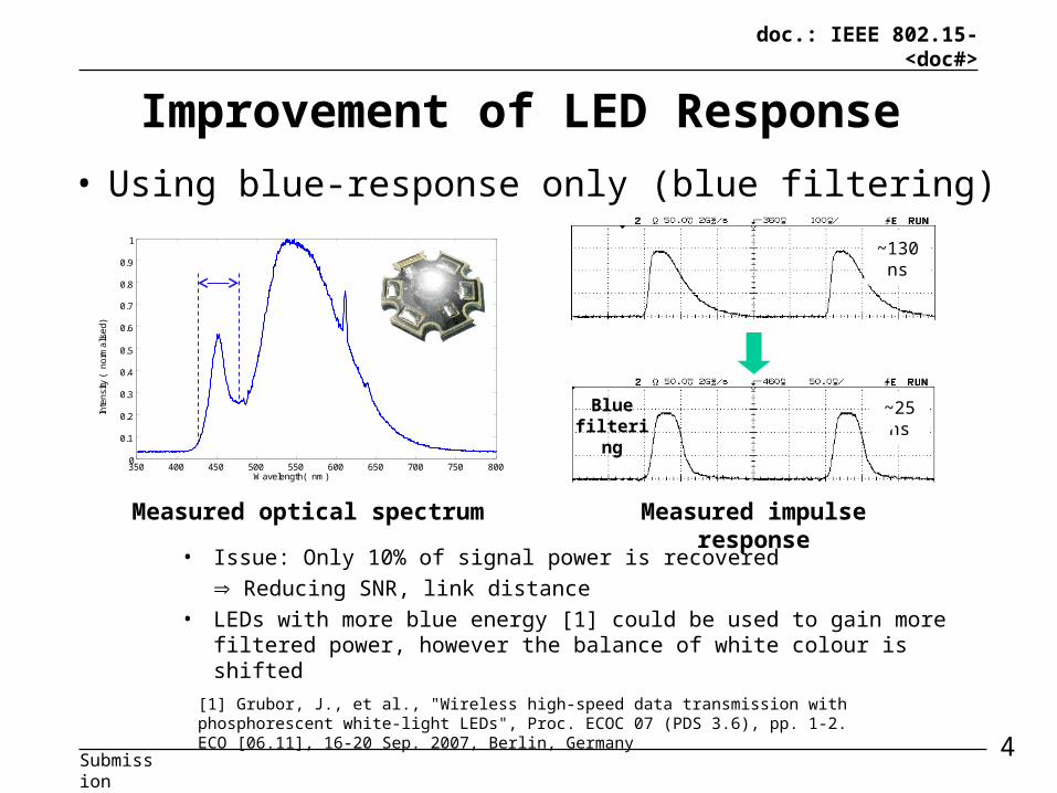
Improvement of LED Response
• Using blue-response only (blue filtering)
350 400 450 500 550 600 650 700 750 8000
0.1
0.2
0.3
0.4
0.5
0.6
0.7
0.8
0.9
1
Wavelength( nm)
Inte
nsity
(no
rmal
ised
)
~130 ns
~25 ns
Measured optical spectrum Measured impulse response
• Issue: Only 10% of signal power is recovered
Reducing SNR, link distance
• LEDs with more blue energy [1] could be used to gain more filtered power, however the balance of white colour is shifted
Blue filtering
[1] Grubor, J., et al., "Wireless high-speed data transmission with phosphorescent white-light LEDs", Proc. ECOC 07 (PDS 3.6), pp. 1-2. ECO [06.11], 16-20 Sep. 2007, Berlin, Germany
4
doc.: IEEE 802.15-<doc#>
Submission
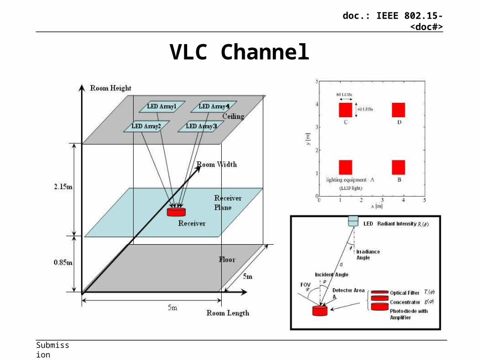
VLC Channel
8

doc.: IEEE 802.15-<doc#>
Submission
Room Power Distribution
• Assume – 1% modulation of
typical illumination power
– Typical receiver performance
• Conclusions– Very high SNR
available• SNRmin = 38.50dB• SNRmax = 49.41dB
– Modulation limited by source bandwidth
9
doc.: IEEE 802.15-<doc#>
Submission
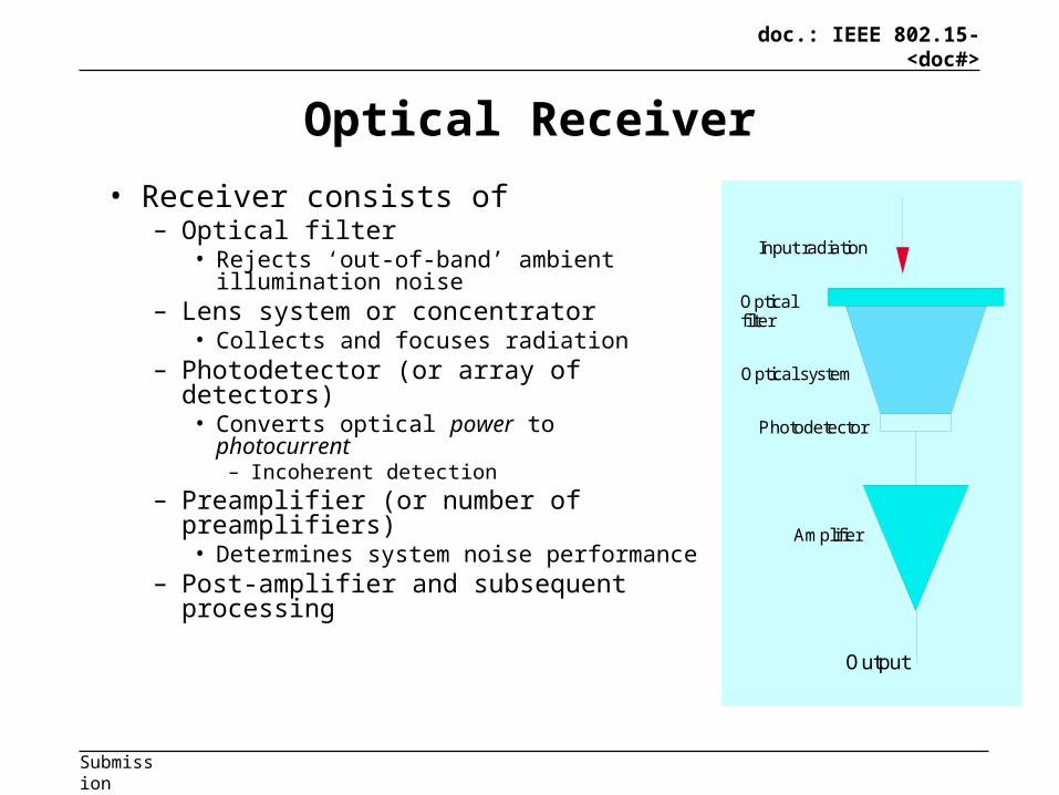
Optical Receiver
• Receiver consists of– Optical filter
• Rejects ‘out-of-band’ ambient illumination noise
– Lens system or concentrator• Collects and focuses radiation
– Photodetector (or array of detectors)• Converts optical power to photocurrent
– Incoherent detection– Preamplifier (or number of
preamplifiers)• Determines system noise performance
– Post-amplifier and subsequent processing
Optical filter
Optical system
Photodetector
Amplifier
Output
Input radiation
11
doc.: IEEE 802.15-<doc#>
Submission
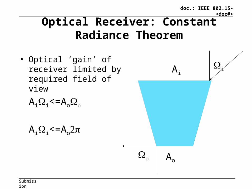
Optical Receiver: Constant Radiance Theorem
• Optical ‘gain’ of receiver limited by required field of view
i
Ai
Ao
Aii<=Ao
Aii<=Ao
12
doc.: IEEE 802.15-<doc#>
Submission
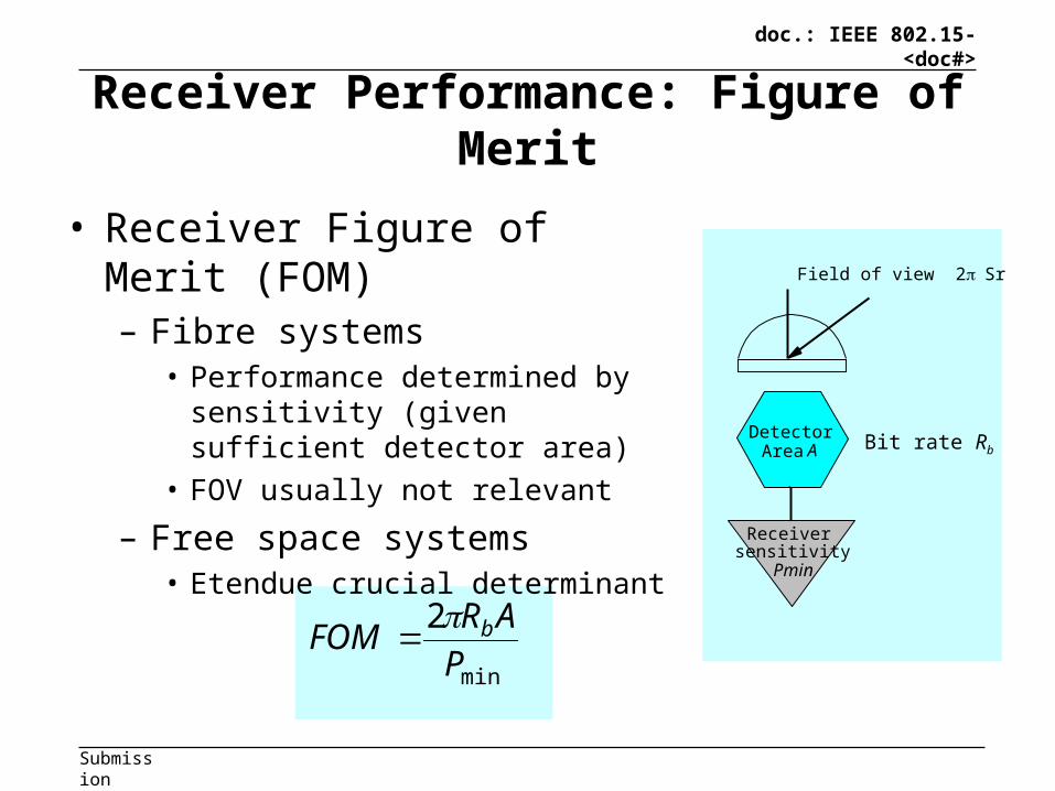
Receiver Performance: Figure of Merit
• Receiver Figure of Merit (FOM)– Fibre systems
• Performance determined by sensitivity (given sufficient detector area)
• FOV usually not relevant
– Free space systems• Etendue crucial determinant
min
2
P
ARFOM b
Detector Area A
Receiver sensitivity Pmin
Field of view 2Sr
Bit rate Rb
13

doc.: IEEE 802.15-<doc#>
Submission
Improving data rate: equalisation
• Transmitter equalisation– High bandwidth– Energy efficiency
• Blue filtering– Lose low frequency energy from phosphor
• Receiver– Simple analogue equalisation– More complex also

doc.: IEEE 802.15-<doc#>
Submission
Typical waveforms for RX equalisation
Data rate 33Mb/s
0 500 1000 1500 2000 2500 3000 3500-0.2
0
0.2
0.4
0.6
0.8
1
1.2
time(ns)
Sig
nal
Recovered datatransmitted data
Data rate 14Mb/s
0 500 1000 1500 2000 2500 3000 3500 4000-0.2
0
0.2
0.4
0.6
0.8
1
1.2
time(ns)
Sig
nal
Recovered datatransmitted data
NRZ data Manchester data
doc.: IEEE 802.15-<doc#>
Submission
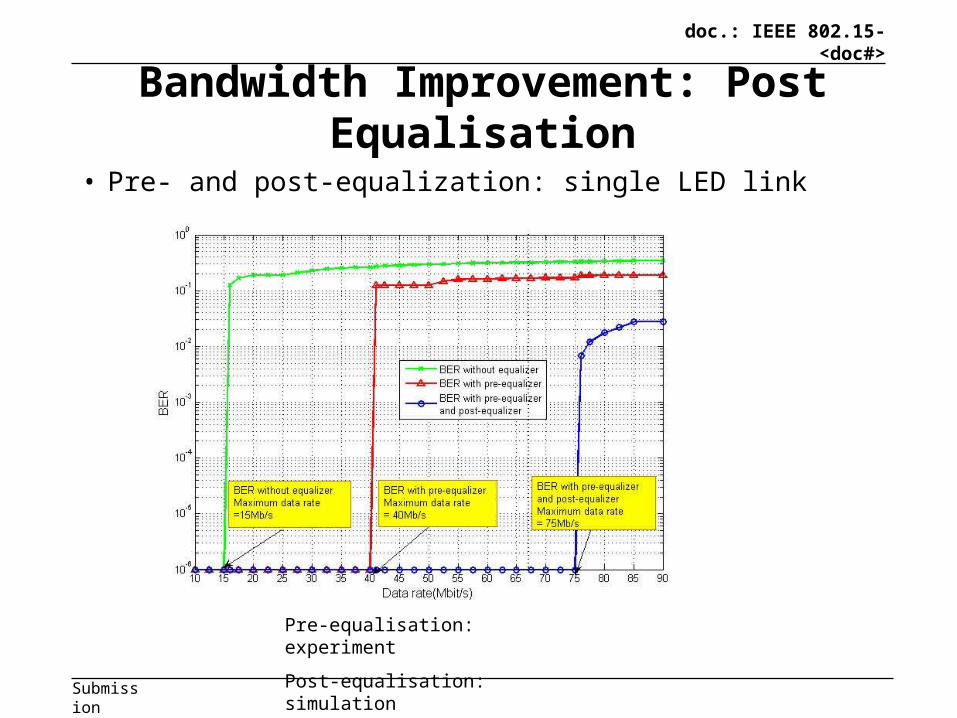
Bandwidth Improvement: Post Equalisation
Pre-equalisation: experiment
Post-equalisation: simulation17
• Pre- and post-equalization: single LED link

doc.: IEEE 802.15-<doc#>
Submission
Improving data rate: complex modulation
• High SNR channel– Complex modulation attractive
• OFDM– 100Mb/s over 20MHz channel [1]
• PAM – Simulations show LED characteristics not
optimal
[1] Grubor, J., et al., "Wireless high-speed data transmission with phosphorescent white-light LEDs", Proc. ECOC 07 (PDS 3.6), pp. 1-2. ECO [06.11], 16-20 Sep. 2007, Berlin, Germany
doc.: IEEE 802.15-<doc#>
Submission
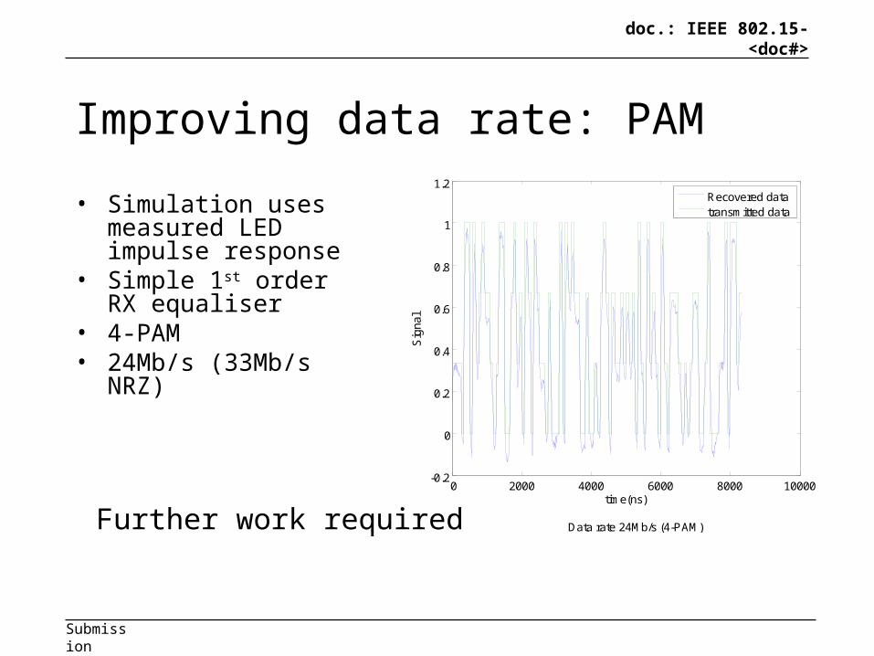
Improving data rate: PAM
• Simulation uses measured LED impulse response
• Simple 1st order RX equaliser
• 4-PAM• 24Mb/s (33Mb/s NRZ)
Data rate 24Mb/s (4-PAM)
time(ns)0 2000 4000 6000 8000 10000
-0.2
0
0.2
0.4
0.6
0.8
1
1.2
Sig
nal
Recovered datatransmitted data
Further work required
doc.: IEEE 802.15-<doc#>
Submission
Improving data rate: MIMO
• Parallel ‘alignment free’ data links
• Simulations show linear capacity growth
• Experimental results for a simple IR system
• Simulations of in-room VLC system

doc.: IEEE 802.15-<doc#>
Submission
Simple IR system
1x2 Laser array
3x3 photodiode array
0.4 0.6 0.8 1 1.2 1.4 1.6 1.8
x 10 -6
0
0.5
0.4 0.6 0.8 1 1.2 1.4 1.6 1.8
x 10 -6
0
0.5
1
Nor
mal
ised
Am
plitu
deN
orm
alis
ed A
mpl
itude
Channel 1
Channel 2
Experimental system
Recovered data Transmitted data
x

doc.: IEEE 802.15-<doc#>
Submission
MIMO VLC: Simulation System
24

doc.: IEEE 802.15-<doc#>
Submission
MIMO VLC: Preliminary Results
Position of the receiverAggregate data rate is linearly proportional to the
number of channels and channel rate
25

doc.: IEEE 802.15-<doc#>
Submission
Providing an uplink
• VLC good at broadcast
• Uplink difficult to achieve– Retro-reflectors
• Low speed• Low cost
– IR uplink• Separate system• Infrastructure complex and expensive
doc.: IEEE 802.15-<doc#>
Submission
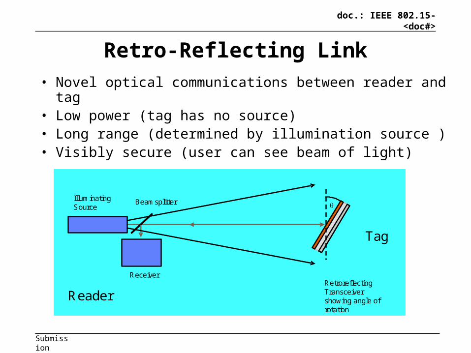
Retro-Reflecting Link
• Novel optical communications between reader and tag• Low power (tag has no source)• Long range (determined by illumination source )• Visibly secure (user can see beam of light)
Illuminating Source
Beamsplitter
ReceiverRetroreflectingTransceiver showing angle of rotation
Reader
Tag
Illuminating Source
Beamsplitter
ReceiverRetroreflectingTransceiver showing angle of rotation
Illuminating Source
Beamsplitter
ReceiverRetroreflectingTransceiver showing angle of rotation
Reader
Tag
18

doc.: IEEE 802.15-<doc#>
Submission
Cooperative communications
O'Brien, D.C.: ‘Cooperation and cognition in optical wireless communications’, in Fitzek, M.K.a.F. (Ed.): ‘Cognitive Wireless Networks: Concepts, Methodologies and Visions - Inspiring the Age of Enlightenment of Wireless Communications -’ (Springer, 2007)
RF transceiver
Base station
VLC transmitter
RF communications
Optical com
munications
RF transceiver
Terminal
VLC receiver
Terminal outside hotspot Terminal within hotspot
RF transceiver 1
Terminal
VLC receiver
RF
comm
unications

doc.: IEEE 802.15-<doc#>
Submission
Providing an uplink: Cooperative systems
• Combine VLC with RF• Optical downlink only• RF uplink/downlink
– 100Mb/s downlink/10Mb/s RF LAN– Fuzzy logic decision making– Typical traffic asymmetry– Significant performance benefits using combination
Hou-J, and O'Brien-Dc: ‘Vertical handover-decision-making algorithm using fuzzy logic for the integrated Radio-and-OW system’, IEEE Transactions on Wireless Communications, 2006, 5, (1), pp. 176-185

doc.: IEEE 802.15-<doc#>
Submission
Compatibility with lighting• Most modern systems use PWM dimming
– Channel does not exist when light is dimmed
• Solutions– Use modulation scheme that ‘incorporates’ PWM
dimming (PPM-like)– Use sensing to only transmit in active regions– But both reduce overall data rate
• Requirement for closer collaboration with lighting industry.

doc.: IEEE 802.15-<doc#>
Submission
Conclusions
• VLC offers high SNR low bandwidth channel– Naturally suited to broadcast
• Challenges– Data rate– Uplink– Compatibility
• If overcome possibility of low cost method to augment wireless capacity