doc.: IEEE 802.11-16/0024r1 · Web viewThe Length subfield of the Common Info field indicates...
215
CTPClassification=CTP_PUBLIC, VisualMarkings= doc.: IEEE 802.11-16/0024r1 IEEE P802.11 Wireless LANs Proposed TGax draft specification Date: 2016-03-02 Author(s): Proposd TGax draft specificationpage 1 1 2 1
Transcript of doc.: IEEE 802.11-16/0024r1 · Web viewThe Length subfield of the Common Info field indicates...

CTPClassification=CTP_PUBLIC, VisualMarkings=doc.: IEEE 802.11-16/0024r1
IEEE P802.11Wireless LANs
Proposed TGax draft specification
Date: 2016-03-02Author(s):
Proposd TGax draft specification page 1
1
2
1
CTPClassification=CTP_PUBLIC, VisualMarkings=doc.: IEEE 802.11-16/0024r1
Proposd TGax draft specification page 2
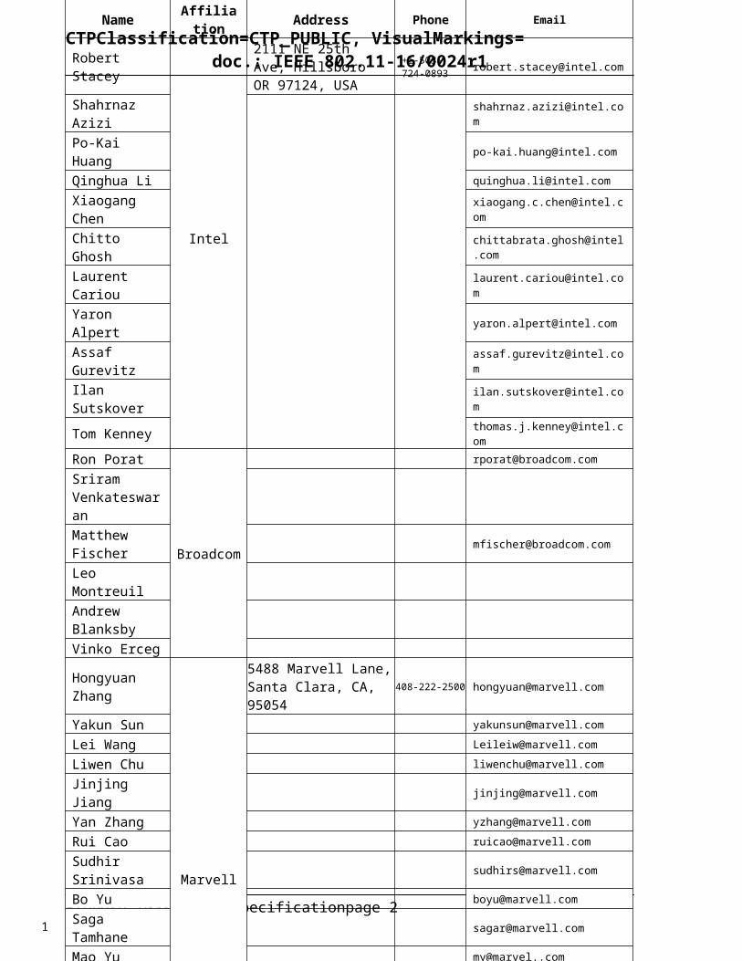
Name Affiliation Address Phone Email
Robert Stacey
Intel
2111 NE 25th Ave, Hillsboro OR 97124, USA
+1-503-724-0893 [email protected]
Shahrnaz Azizi [email protected]
Po-Kai Huang [email protected]
Qinghua Li [email protected]
Xiaogang Chen [email protected]
Chitto Ghosh [email protected]
Laurent Cariou [email protected]
Yaron Alpert [email protected]
Assaf Gurevitz [email protected]
Ilan Sutskover [email protected]
Tom Kenney [email protected]
Ron Porat
Broadcom
Sriram Venkateswaran Matthew Fischer [email protected]
Leo MontreuilAndrew BlanksbyVinko Erceg
Hongyuan Zhang
Marvell
5488 Marvell Lane,Santa Clara, CA, 95054
408-222-2500 [email protected]
Yakun Sun [email protected]
Lei Wang [email protected]
Liwen Chu [email protected]
Jinjing Jiang [email protected]
Yan Zhang [email protected]
Rui Cao [email protected]
Sudhir Srinivasa [email protected]
Bo Yu [email protected]
Saga Tamhane [email protected]
Mao Yu [email protected]
Xiayu Zheng [email protected]
Christian Berger [email protected]
Niranjan Grandhe [email protected]
Hui-Ling Lou [email protected]
Alice Chen 5775 Morehouse Dr. San Diego, CA, USA
Albert Van ZelstStraatweg 66-S Breukelen, 3621 BR Netherlands
Alfred Asterjadhi
5775 Morehouse Dr. San Diego, CA, USA
Arjun Bharadwaj
5775 Morehouse Dr. San Diego, CA, USA
Bin Tian 5775 Morehouse Dr. San Diego, CA, USA
Carlos Aldana1700 Technology Drive San Jose, CA 95110, USA
George Cherian 5775 Morehouse Dr. San Diego, CA, USA
Gwendolyn Barriac
5775 Morehouse Dr. San Diego, CA, USA
Hemanth 5775 Morehouse Dr. San
1

CTPClassification=CTP_PUBLIC, VisualMarkings=doc.: IEEE 802.11-16/0024r1
Proposd TGax draft specification page 3
AbstractThis document contains a proposal for the TGax draft amendment. It captures the feature requirements outlined in the TGax specification framework document (11-15/0132) in detailed draft text.
1
2
3
4
5
1

CTPClassification=CTP_PUBLIC, VisualMarkings=doc.: IEEE 802.11-16/0024r1
1 Preface
1.1 Revision historyRevision Date Changes0 January 15, 2016 Initial draft1 March 2, 2016 Created a new MAC clause and moved most of the MAC stuff there. Added text
contributions for recent SFD additions. Additional authors.
1.2 NotationEditing instructions are shown in bold italic.
Editor’s notes in red bold italics are provided to aid in drafting the document. For example, missing text or indicating the placement of future text.
1.3 Baseline documentThis document is written as an amendment to the Draft P802.11-REVmc/D5.00 revision of the 802.11 specification as amended by Draft P802.11ai/D6.3 and Draft P802.11ah/D6.0.
2 Normative references
3 Definitions, acronyms, and abbreviations
3.1 Definitions
3.2 Definitions specific to IEEE Std 802.11
3.3 Definitions specific to IEEE 802.11 operation in some regulatory domains
3.4 Abbreviations and acronyms
Insert the following acronym definitions:
DL DowlinkDL MU Downlink multi-userHE High EfficiencyOFDMA Orthogonal Frequency-Division Multiple AccessMU-RTS Multi-user request to sendUL Uplink
Proposd TGax draft specification page 4
1
2
34567
89
10
11
12
13
14
15
16
17181920212223242526
1

CTPClassification=CTP_PUBLIC, VisualMarkings=doc.: IEEE 802.11-16/0024r1
3.5 Abbreviations and acronyms in some regulatory domains
4 General description
4.3 Components of the IEEE Std 802.11 architecture
4.3.12a High efficiency (HE) STAThe IEEE Std 802.11 HE STA operates in frequency bands between 1 GHz and 6 GHz.
An HE STA is VHT STA that, in addition to the features supported as a VHT STA, supports the MAC features defined in Clause 25 and the PHY features defined in Clause 26.
5 MAC service definition
6 Layer management
6.3 MLME SAP interface
6.3.7 Associate6.3.7.2 MLME-ASSOCIATE.request6.3.7.2.2 Semantics of the service primitiveInsert the following new parameter into the primitive:
HE Capabilities
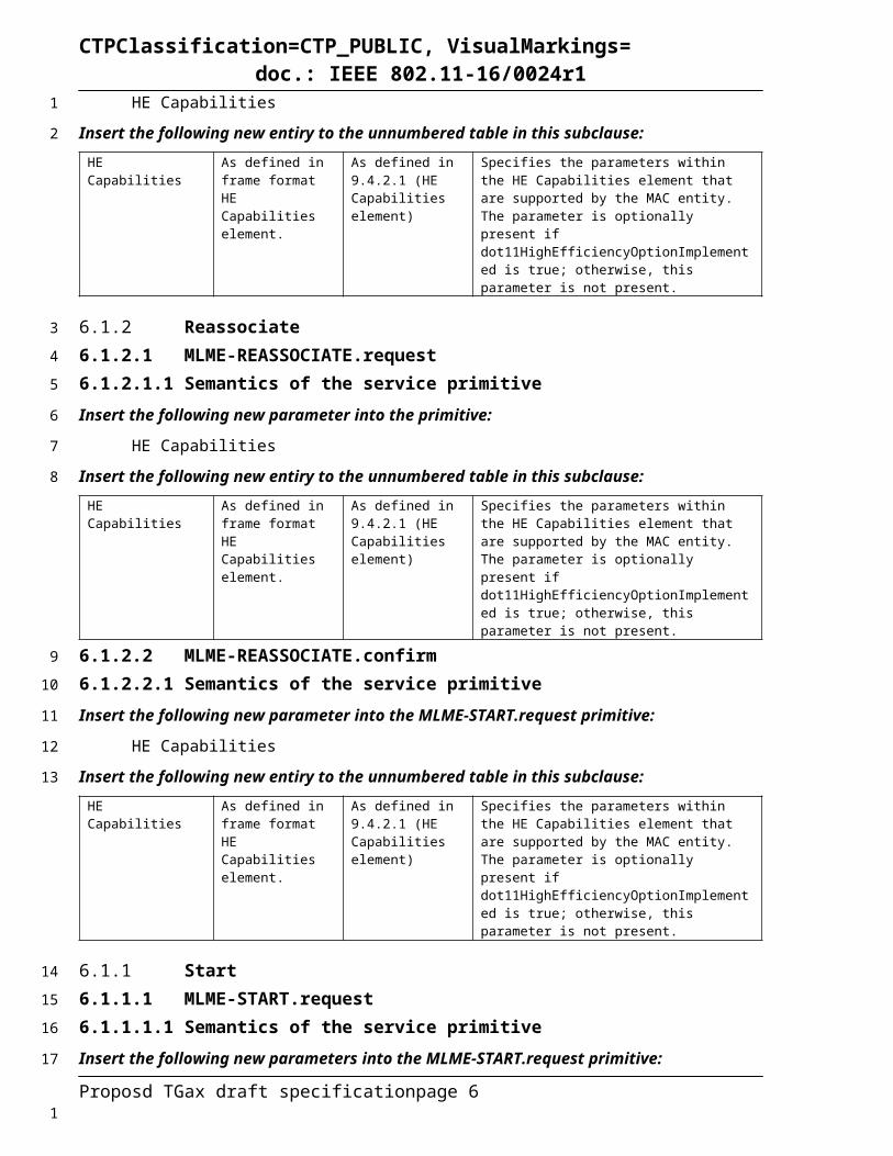
Insert the following new entiry to the unnumbered table in this subclause:HE Capabilities As defined in frame
format HE Capabilities element.
As defined in 9.4.2.213 (HE Capabilities element)
Specifies the parameters within the HE Capabilities element that are supported by the MAC entity. The parameter is optionally present if dot11HighEfficiencyOptionImplemented is true; otherwise, this parameter is not present.
6.3.7.3 MLME-ASSOCIATE.confirm6.3.7.3.2 Semantics of the service primitiveInsert the following new parameter into the primitive:
HE Capabilities
Insert the following new entiry to the unnumbered table in this subclause:HE Capabilities As defined in frame
format HE Capabilities element.
As defined in 9.4.2.213 (HE Capabilities element)
Specifies the parameters within the HE Capabilities element that are supported by the MAC entity. The parameter is optionally present if dot11HighEfficiencyOptionImplemented is true; otherwise, this parameter is not present.
6.3.8 Reassociate6.3.8.2 MLME-REASSOCIATE.request6.3.8.2.2 Semantics of the service primitiveInsert the following new parameter into the primitive:
HE Capabilities
Proposd TGax draft specification page 5
1
2
3
4
5
67
8
9
10
11
12
13
14
15
16
17
18
19
20
21
22
23
24
25
26
1
CTPClassification=CTP_PUBLIC, VisualMarkings=doc.: IEEE 802.11-16/0024r1
Insert the following new entiry to the unnumbered table in this subclause:HE Capabilities As defined in frame
format HE Capabilities element.
As defined in 9.4.2.213 (HE Capabilities element)
Specifies the parameters within the HE Capabilities element that are supported by the MAC entity. The parameter is optionally present if dot11HighEfficiencyOptionImplemented is true; otherwise, this parameter is not present.
6.3.8.3 MLME-REASSOCIATE.confirm6.3.8.3.1 Semantics of the service primitiveInsert the following new parameter into the MLME-START.request primitive:
HE Capabilities
Insert the following new entiry to the unnumbered table in this subclause:HE Capabilities As defined in frame
format HE Capabilities element.
As defined in 9.4.2.213 (HE Capabilities element)
Specifies the parameters within the HE Capabilities element that are supported by the MAC entity. The parameter is optionally present if dot11HighEfficiencyOptionImplemented is true; otherwise, this parameter is not present.
6.3.11 Start6.3.11.2 MLME-START.request6.3.11.2.2 Semantics of the service primitiveInsert the following new parameters into the MLME-START.request primitive:
HE Capbilities
HE Operation
Insert the following new entires to the unnumbered table in this subclause:Name Type Valid Range DescriptionHE Capabilities As defined in frame
format HE Capabilities element.
As defined in 9.4.2.213 (HE Capabilities element)
The HE capabilities to be advertised for the BSS. The parameter is present if dot11HighEfficiencyOptionImplemented is true; otherwise, this parameter is not present.
HE Operation As defined in frame format HE Operation element.
As defined in 9.4.2.214 (HE Operation element)
The additional HE capabilities to be advertised for the BSS. The parameter is present if BSSType = INFRASTRUCTURE and dot11HighEfficiencyOptionImplemented is true; otherwise, this parameter is not present.
Proposd TGax draft specification page 6
1
2
3
4
5
6
7
8
9
10
11
12
13
1

CTPClassification=CTP_PUBLIC, VisualMarkings=doc.: IEEE 802.11-16/0024r1
7 DS SAP specification
8 PHY service specification
9 Frame formats
9.1 General requirements
9.2 MAC frame formats
1.1.1
1.1.2
1.1.3
9.22.1
9.22.2
9.22.3
9.2.4 Frame fields9.2.4.1 Frame Control field9.2.4.1.3 Type and Subtype fieldsChange the row below and insert a new row immediately after it in Table 8-1 as follows:
Table 9-1 - Valid type and subtype combinations
Type valueB3 B2
Type Subtype valueB7 B6 B5 B4
Subtype description
01 Control 0000-0011<ANA> Reserved01 Control <ANA> Trigger
9.2.4.1.10 Order fieldChange as follows:
The Order field is 1 bit in length. It is used for two purposes:
— It is set to 1 in a non-QoS Data frame transmitted by a non-QoS STA to indicate that the frame contains an MSDU, or fragment thereof, that is being transferred using the StrictlyOrdered service class.
— It is set to 1 in a QoS Data or Management frame transmitted with a value of HT_GF, HT_MF, or VHT, or HE for the FORMAT parameter of the TXVECTOR to indicate that the frame contains an HT Control field.
Otherwise, the Order field is set to 0.NOTE—The Order field is always set to 0 for frames transmitted by a DMG STA.
Proposd TGax draft specification page 7
1
2
3
4
5
6
7
8
9
10
11
12
13
14
15
16
17
18
19
20
212223
242526
27
28
1

CTPClassification=CTP_PUBLIC, VisualMarkings=doc.: IEEE 802.11-16/0024r1
1.1.3.11.1.3.21.1.3.31.1.3.41.1.3.59.22.3.19.22.3.29.22.3.39.22.3.49.22.3.59.2.4.6 HT Control field9.2.4.6.1 GeneralRemove Figure 9-7 (HT Control field).
Insert Table 9-9a (HT Control field) as follows:Table 9-9a – HT Control field
Variant Bit 0 (value) Bit 1 (value) Bit 2-29 Bit 30 Bit 31
HT variant VHT (0) HT Control Middle AC Constraint RDG/More PPDU
VHT variant VHT (1) HE (0) VHT Control Middle AC Constraint RDG/More PPDU
HE variant VHT(1) HE (1) Aggregated Control
Change the paragraphs below of 9.2.4.6.1 as follows:
The HT Control field has two different forms, the HT variant, and the VHT variant, and the HE variant. These forms differ in the values of the VHT and/or HE subfields and in their formats, which are shown in Table 8-9a (HT Control field).
The VHT subfield is set to 0 to indicate a HT variant HT Control field. The VHT subfield is set to 1 and the HE subfield is set to 0 to indicate a VHT variant HT Control field. The VHT subfield is set to 1 and the HE subfield is set to 1 to indicate a HE variant HE Control field.
The two forms differ in the format of tThe HT Control Middle subfield, described is defined in 8.2.4.6.2 (HT variant) for the HT variant and
The VHT Control Middle subfield is defined in 8.2.4.6.3 (VHT variant) for the VHT variant and in the value of the VHT subfield.
The Aggregated Control subfield is defined in 8.2.4.6.4 (HE variant).
The VHT subfield of the HT Control field indicates whether the HT Control Middle subfield is the VHT Variant or the HT Variant. The VHT subfield is set to 1 to indicate that the HT Control Middle subfield is the VHT Variant and is set to 0 to indicate that the HT Control Middle subfield is the HT Variant.
1.1.3.5.11.1.3.5.29.22.3.5.19.2.4.6.3 VHT variantChange the paragraph below as follows:
Proposd TGax draft specification page 8
1
2
3
4
5
6
7
8
9
10
11
12
13
14
15
16
17
181920
212223
2425
2627
28
293031
32
33
34
35
36
1

CTPClassification=CTP_PUBLIC, VisualMarkings=doc.: IEEE 802.11-16/0024r1
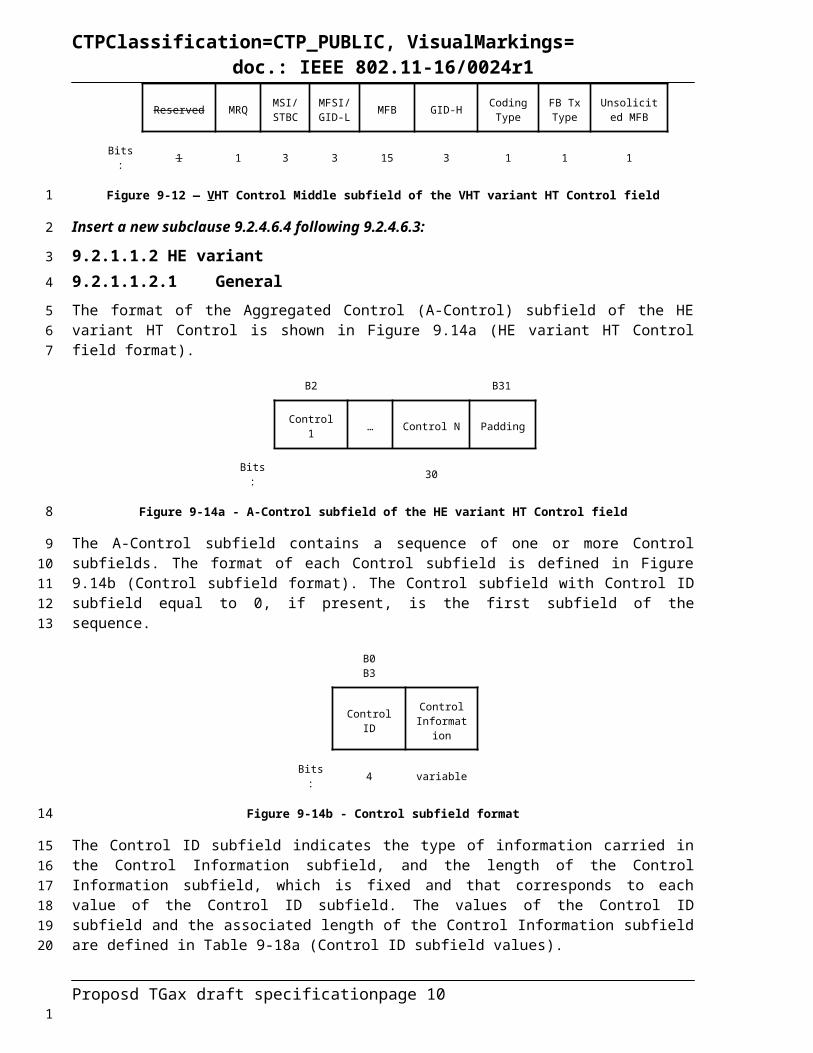
The format of the VHT Control Middle subfield of the VHT variant HT Control field is shown in Figure 9-12 (VHT Control Middle subfield of the VHT variant HT Control field).
Change Figure 9-12 as follows:
B1 B2 B3 B5 B6 B8 B9 B23 B24 B26 B27 B28 B29
Reserved MRQ MSI/STBC
MFSI/GID-L MFB GID-H Coding
TypeFB Tx Type
Unsolicited MFB
Bits: 1 1 3 3 15 3 1 1 1
Figure 9-12 — VHT Control Middle subfield of the VHT variant HT Control field
Insert a new subclause 9.2.4.6.4 following 9.2.4.6.3:
9.2.4.6.4 HE variant9.2.4.6.4.1 GeneralThe format of the Aggregated Control (A-Control) subfield of the HE variant HT Control is shown in Figure 9.14a (HE variant HT Control field format).
B2 B31
Control 1 … Control N Padding
Bits: 30
Figure 9-14a - A-Control subfield of the HE variant HT Control field
The A-Control subfield contains a sequence of one or more Control subfields. The format of each Control subfield is defined in Figure 9.14b (Control subfield format). The Control subfield with Control ID subfield equal to 0, if present, is the first subfield of the sequence.
B0 B3
Control ID Control Information
Bits: 4 variable
Figure 9-14b - Control subfield format
The Control ID subfield indicates the type of information carried in the Control Information subfield, and the length of the Control Information subfield, which is fixed and that corresponds to each value of the Control ID subfield. The values of the Control ID subfield and the associated length of the Control Information subfield are defined in Table 9-18a (Control ID subfield values).
Table 9-18a - Control ID subfield values
Control ID value Meaning Length, in bits, of the
Control Information subfieldContents of the
Control Information subfield
0 UL MU response scheduling TBD See 8.2.4.6.4.2 (UL MU response scheduling)
1 Receive operation mode indication TBD See 8.2.4.6.4.3 (Receive operation mode indication)
Proposd TGax draft specification page 9
12
3
4
5
6
7
89
10
111213
14
15161718
19
1
CTPClassification=CTP_PUBLIC, VisualMarkings=doc.: IEEE 802.11-16/0024r1
2 HE link adaptation TBD See 8.2.4.6.4.4 (HE link adaptation)
TBD …
8-15 Reserved
The Control Information subfield carries control information that depends on the Control ID value, as defined in Table 9-18a (Control ID subfield values).
The Padding subfield follows the last Control subfield and is set to a sequence of zeros so that the length of the A-Control subfield is 30 bits.
9.2.4.6.4.2 UL MU response schedulingThe Control Information subfield, when the Control ID subfield is 0, contains scheduling information for an HE trigger-based PPDU that carries an immediate acknowledgement, which is sent as a response to the soliciting A-MPDU (see 9.42.2 (UL MU operation)).
The format of the Control Information subfield is defined in Figure 9-14c (Control Information subfield format when Control ID subfield is 0).
B0 B8 B9 B8+X B9+X B8+X+Y
UL PPDU Length RU Allocation TBD
Bits: 9 X Y
Figure 9-14c - Control Information subfield format when Control ID subfield is 0
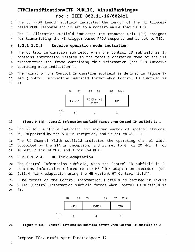
The UL PPDU Length subfield indicates the length of the HE trigger-based PPDU response and is set to a nonzero value that is TBD.
The RU Allocation subfield indicates the resource unit (RU) assigned for transmitting the HE trigger-based PPDU response and is set to TBD.
9.2.4.6.4.3 Receive operation mode indicationThe Control Information subfield, when the Control ID subfield is 1, contains information related to the receive operation mode of the STA transmitting the frame containing this information (see 25.8 (Receive operating mode indication)).
The format of the Control Information subfield is defined in Figure 9-14d (Control Information subfield format when Control ID subfield is 1).
B0 B2 B3 B4 B5 B4+X
RX NSS RX Channel Width TBD
Bits: 3 2 X
Figure 9-14d - Control Information subfield format when Control ID subfield is 1
The RX NSS subfield indicates the maximum number of spatial streams, NSS, supported by the STA in reception, and is set to NSS – 1.
The RX Channel Width subfield indicates the operating channel width supported by the STA in reception, and is set to 0 for 20 MHz, 1 for 40 MHz, 2 for 80 MHz, and 3 for 160 MHz.
Proposd TGax draft specification page 10
12
34
5
678
910
11
1213
1415
16
171819
2021
22
2324
2526
1

CTPClassification=CTP_PUBLIC, VisualMarkings=doc.: IEEE 802.11-16/0024r1
9.2.4.6.4.4 HE link adaptationThe Control Information subfield, when the Control ID subfield is 2, contains information related to the HE link adaptation procedure (see 9.31.4 (Link adaptation using the HE variant HT Control field)).
The format of the Control Information subfield is defined in Figure 9-14e (Control Information subfield format when Control ID subfield is 2).
B0 B2 B3 B6 B7 B6+X
NSS HE-MCS TBD
Bits: 3 4 X
Figure 9-14e - Control Information subfield format when Control ID subfield is 2
The NSS subfield indicates the recommended number of spatial streams, NSS, and is set to NSS – 1.
The HE-MCS subfield indicates the recommended HE-MCS, and is set to the HE-MCS Index value (defined in 26.5 (Parameters for HE-MCSs)).
9.2.5 Duration/ID field (QoS STA)9.2.5.2 Setting for single and multiple protection under enhanced distributed
channel access (EDCA)Change item a) of the 2nd paragraph of this subclause as follows:
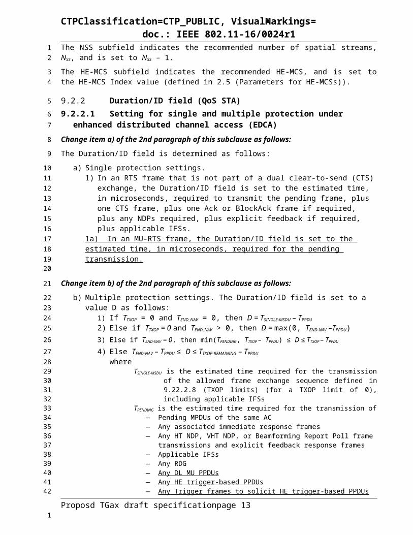
The Duration/ID field is determined as follows:
a) Single protection settings.1) In an RTS frame that is not part of a dual clear-to-send (CTS) exchange, the Duration/ID field
is set to the estimated time, in microseconds, required to transmit the pending frame, plus one CTS frame, plus one Ack or BlockAck frame if required, plus any NDPs required, plus explicit feedback if required, plus applicable IFSs.
1a) In an MU-RTS frame, the Duration/ID field is set to the estimated time, in microseconds, required for the pending transmission.
Change item b) of the 2nd paragraph of this subclause as follows:
b) Multiple protection settings. The Duration/ID field is set to a value D as follows:1) If TTXOP = 0 and TEND_NAV = 0, then D = TSINGLE-MSDU – TPPDU
2) Else if TTXOP = 0 and TEND_NAV > 0, then D = max(0, TEND-NAV –TPPDU)3) Else if TEND-NAV = 0, then min(TPENDING, TTXOP – TPPDU) ≤ D ≤ TTXOP – TPPDU 4) Else TEND-NAV – TPPDU ≤ D ≤ TTXOP-REMAINING – TPPDU
whereTSINGLE-MSDU is the estimated time required for the transmission of the allowed frame
exchange sequence defined in 9.22.2.8 (TXOP limits) (for a TXOP limit of 0), including applicable IFSs
TPENDING is the estimated time required for the transmission of— Pending MPDUs of the same AC— Any associated immediate response frames— Any HT NDP, VHT NDP, or Beamforming Report Poll frame transmissions and
explicit feedback response frames— Applicable IFSs— Any RDG— Any DL MU PPDUs — Any HE trigger-based PPDUs
Proposd TGax draft specification page 11
1
23
45
6
7
89
10
1112
13
14
1516171819202122
23
242526
272829303132333435363738394041
1
CTPClassification=CTP_PUBLIC, VisualMarkings=doc.: IEEE 802.11-16/0024r1
— Any Trigger frames to solicit HE trigger-based PPDUs TTXOP is the duration given by dot11EDCATable-TXOPLimit (dot11QAP-
EDCATableTXOPLimit for the AP) for that ACTTXOP-REMAINING is TTXOP less the time already used time within the TXOPTEND-NAV is the remaining duration of any NAV set by the TXOP holder, or 0 if no NAV
has been establishedTPPDU is the time required for transmission of the current PPDU
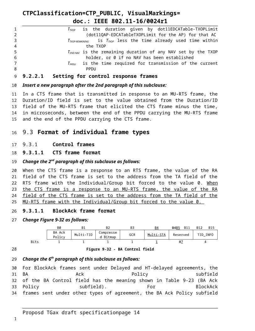
9.2.5.7 Setting for control response framesInsert a new paragraph after the 2nd paragraph of this subclause:
In a CTS frame that is transmitted in response to an MU-RTS frame, the Duration/ID field is set to the value obtained from the Duration/ID field of the MU-RTS frame that elicited the CTS frame minus the time, in microseconds, between the end of the PPDU carrying the MU-RTS frame and the end of the PPDU carrying the CTS frame.
9.3 Format of individual frame types
9.3.1 Control frames9.3.1.3 CTS frame formatChange the 2nd paragraph of this subclause as follows:
When the CTS frame is a response to an RTS frame, the value of the RA field of the CTS frame is set to the address from the TA field of the RTS frame with the Individual/Group bit forced to the value 0. When the CTS frame is a response to an MU-RTS frame, the value of the RA field of the CTS frame is set to the address from the TA field of the MU-RTS frame with the Individual/Group bit forced to the value 0.
9.3.1.9 BlockAck frame formatChange Figure 9-32 as follows:
B0 B1 B2 B3 B4 B4B5 B11 B12 B15BA AckPolicy Multi-TID Compressed
Bitmap GCR Multi-STA Reserved TID_INFO
Bits 1 1 1 1 1 87 4
Figure 9-32 - BA Control field
Change the 6th paragraph of this subclause as follows:
For BlockAck frames sent under Delayed and HT-delayed agreements, the BA Ack Policy subfieldof the BA Control field has the meaning shown in Table 9-23 (BA Ack Policy subfield). For BlockAckframes sent under other types of agreement, the BA Ack Policy subfield is reserved. A BlockAck frame with the Multi-STA subfield equal to 1 is not sent under Delayed and HT-delayed agreements.
Change Table 9-24 as follows:Table 9-24 - Block Ack frame variant encoding
Multi-TIDsubfield
value
Compressed Bitmap
subfield value
GCRsubfield
value
Multi-STASubfield
value
BlockAck frame variant
0 0 0 0 Basic BlockAck0 1 0 0 Compressed BlockAck
1 0 0 0Extended CompressedBlockAck
1 1 0 0 Multi-TID BlockAck0 0 1 0 Reserved0 1 1 0 GCR Block Ack1 0 1 0 Reserved1 1 1 0 Reserved
Proposd TGax draft specification page 12
12345678
9
10111213
14
15
16
17
18192021
22
23
24
25
26272829
30
31
1
CTPClassification=CTP_PUBLIC, VisualMarkings=doc.: IEEE 802.11-16/0024r1
0 0 0 1 Reserved0 1 0 1 Reserved1 0 0 1 Reserved1 1 0 1 Multi-STA BlockAck0 0 1 1 Reserved0 1 1 1 Reserved1 0 1 1 Reserved1 1 1 1 Reserved
Change the 7th paragraph of this subclause as follows:
The values of the Multi-TID, Compressed Bitmap, and GCR and Multi-STA subfields of the BA Control field determine which of the BlockAck frame variants is represented, as indicated in the Table 9-24.
9.3.1.9.3 Compressed BlockAck variantChange subclause 9.3.1.9.3 as follows:
The TID_INFO subfield of the BA Control field of the Compressed BlockAck frame contains the TID for which this BlockAck frame is sent.
The BA Information field of the Compressed BlockAck frame comprises the Block Ack Starting Sequence Control subfield and the Block Ack Bitmap subfield, as shown in Figure 9-34 (BA Information field (Compressed BlockAck)). The Starting Sequence Number subfield of the Block Ack Starting Sequence Control subfield contains the sequence number of the first MSDU or A-MSDU for which this BlockAck frame is sent. The value of this subfield is defined in 10.24.7.5 (Generation and transmission of BlockAck frames by an HT STA or DMG STA). The Fragment Number subfield of the Block Ack Starting Sequence Control subfield is set to 0.
When the Fragment Number subfield is 0, Tthe Block Ack Bitmap subfield of the BA Information field of the Compressed BlockAck frame is 8 octets in length and is used to indicate the received status of up to 64 MSDUs and A-MSDUs. Each bit that is equal to 1 in the compressed Block Ack Bitmap field acknowledges the successful reception of a single MSDU or A-MSDU in the order of sequence number, with the first bit of the Block Ack Bitmap field corresponding to the MSDU or A-MSDU with the sequence number that matches the value of the Starting Sequence Number subfield of the Block Ack Starting Sequence Control subfield.
When the Fragment Number subfield is 1, the Block Ack Bitmap subfield of the BA Information field of the Compressed BlockAck frame is used to indicate the receive status of up to 16 MSDUs and A-MSDUs. Bit position n of the Block Ack Bitmap field, if equal to 1, acknowledges receipt of an MPDU with sequence number value, SN and fragment number value, FN with n equal to 4 × ( SN – SSN ) + FN , where SSN is the value of the Starting Sequence Number subfield of the Block Ack Starting Sequence Control subfield and the operations on the sequence numbers are performed modulo 4096. When bit position n of the Block Ack Bitmap field is equal to 0 it indicates that the MPDU has not been received. NOTE—When the Fragment Number subfield is equal to 1 then the BlockAck Bitmap field is split into 16 subbitmaps, each of which indicates receive status for 4 fragments of each of the 16 MSDUs.
Insert a new subclause after 9.3.1.9.6:
9.3.1.9.7 Multi-STA BlockAck variantThe TID_INFO subfield of the BA Control field of the Multi-STA BlockAck frame is reserved.
The BA Information field of the Multi-STA BlockAck frame comprises one or more instances of the Per STA Info subfields. The Per STA Info subfield is shown in Figure 9-37a.
Per-AID TID Info Block Ack Starting Sequence Control Block Ack Bitmap
Octets 2 0 or 2 0 or 8
Proposd TGax draft specification page 13
1
2
34
5
6
78
9101112131415
16171819202122
23242526272829
3031
32
33
34
3536
1
CTPClassification=CTP_PUBLIC, VisualMarkings=doc.: IEEE 802.11-16/0024r1
Figure 9-37a - Per STA Info subfield format
The Per AID TID Info subfield is shown in Figure 9-37b.B0 B10 B11 B12-B15
AID ACK Type TIDBits 11 1 4
Figure 9-37b - Per AID TID Info subfield format
The AID field carries the AID of the STA for which the Per STA Info field is intended.
The TID field contains the TID for which the acknowledgement or block acknowledgement applies.
If the ACK Type field is 0, then the Block Ack Starting Sequence Control and Block Ack Bitmap are not present and the Per STA Info field indicates the acknowledgement of successful reception of either a single MPDU or of all the MPDUs carried in the eliciting (A-) MPDU. If the ACK Type subfield is 1, then the Block Ack Starting Sequence Control and Block Ack Bitmap fields are present.
When the Fragment Number subfield is 1, the Block Ack Starting Sequence Control subfield is as shown in Figure 9-27. The Block Ack Bitmap subfield of the BA Information field of the Multi-STA BlockAck frame contains an 8-octet block ack bitmap. Each bit that is equal to 1 in the Block Ack Bitmap subfield acknowledges the successful reception of a single MSDU or A-MSDU in the order of sequence number with the first bit of the Block Ack Bitmap subfield corresponding to the MSDU or A-MSDU with the sequence number that matches the value of the Starting Sequence Number subfield of the Block Ack Starting Sequence Control subfield.When the Fragment Number subfield is 1, the Block Ack Bitmap subfield of the BA Information field of the Multi-STA Block Ack frame is used to indicate the receive status of up to 16 MSDUs and A-MSDUs. Bit position n of the Block Ack Bitmap field, if equal to 1, acknowledges receipt of an MPDU with sequence number value, SN and fragment number value, FN with n equal to 4 × (SN – SSN) + FN, where SSN is the value of the Starting Sequence Number subfield of the Block Ack Starting Sequence Control subfield and the operations on the sequence numbers are performed modulo 4096. When bit position n of the Block Ack Bitmap field is equal to 0 it indicates that the MPDU has not been received.NOTE—When the Fragment Number subfield is equal to 1 then the BlockAck Bitmap field is split into 16 subbitmaps, each of which indicates receive status for 4 fragments of each of the 16 MSDUs.
Insert a new subclause after 9.3.1.22:
9.3.1.23 Trigger frameThe Trigger frame is used to allocate resource for UL MU transmission and to solicit an UL MU transmission at [TBD IFS] after the PPDU that carries the Trigger frame. The Trigger frame also carries other information required by the responding STA to send UL MU.
The frame format for the Trigger frame is as defined in Figure 9-51a (Trigger frame).
Frame Control Duration (RA) TA Common
InfoPer User
Info… Per User
InfoPadding FCS
Octets: 2 2 6 6 TBD TBD TBD 4
Figure 9-51a - Trigger frame
The Duration/ID field is set as defined in 9.2.5 (Duration/ID field (QoS STA)).
The RA field of the Trigger frame is the address of the recipient STA. Whether RA is not part of Trigger frame is TBD.
The TA field value is the address of the STA transmitting the Trigger frame.
Proposd TGax draft specification page 14
1
2
3
4
5
6789
10111213141516
17181920212223
2425
26
27
282930
31
32
33
34
3536
37
1

CTPClassification=CTP_PUBLIC, VisualMarkings=doc.: IEEE 802.11-16/0024r1
The Common Info field is defined in Figure 9-51b.Length Cascade
IndicationCS
RequiredHE-SIG-A
InfoCP and LTF
TypeTrigger Type Trigger-
dependent Common Info
Bits: 12 1 1 TBD TBD TBD variable
Figure 9-51b - Common Info field
The Length subfield of the Common Info field indicates the value of the L-SIG Length field of the HE trigger-based PPDU that is the response to the Trigger frame.
If the Cascade Indication subfield is 1, then a subsequent Trigger frame follows the current Trigger frame. Otherwise the Cascade Indication subfield is 0.
The CS Required subfield is set to 1 to indicate that the STAs identified in the Per User Info fields are required to use ED to sense the medium and to consider the medium state and the NAV in determining whether or not to repond. The CS Requred subfield is set to 0 to indicate that the STAs identified in the Per User Info fields are not required consider the medium state or the NAV in determining whether or not to respond.
The HE-SIG-A Info subfield of the Common Info field indicates the content of the HE-SIG-A field of the HE trigger-based PPDU response. The TBD bits in HE-SIG-A of the HE trigger-based PPDU that may be implicitly known by all responding STAs can be excluded.
The CP and LTF Type subfield of the Common Info field indicates the CP and HE-LTF type of the HE trigger-based PPDU response. The CP and LTF field encoding is defined in Table 9-2.
Table 9-2 - CP and LTF field encoding
CP and LTF field value
Description
0 2x LTF + 0.8 µs CP1 2x LTF + 1.6 µs CP2 4x LTF + 3.2 µs CP3-TBD Reserved
The Trigger Type subfield indicates the type of the Trigger frame. The Trigger frame can include an optional type-specific Common Info and optional type-specific Per User Info. Table 9-3 defines the valid Trigger Type.
Table 9-3 - Trigger Type field encoding
Trigger Type value Trigger Type description0 Basic Trigger1 Beamforming Report Poll Trigger2 MU-BAR3 MU-RTS4-TBD Reserved
The Per User Info field is defined in Figure 9-1.
User Indentifier
RU Allocation
Coding Type
MCS DCM SS Allocation
Trigger dependent
Per User InfoBits: 12 TBD TBD TBD TBD TBD variable
Figure 9-1 - Per User Info field
The User Identifier subfield of the Per User Info field indicates the AID of the STA allocated the RU to transmit the MPDU(s) in the HE trigger-based PPDU.
Proposd TGax draft specification page 15
1
2
34
56
789
1011
121314
1516
17
181920
21
22
23
24
25
2627
1

CTPClassification=CTP_PUBLIC, VisualMarkings=doc.: IEEE 802.11-16/0024r1
The RU Allocation subfield of the Per User Info field indicates the RU used by the HE trigger-based PPDU of the STA identified by User Identifier subfield. The length and coding of RU Allocation subfield are TBD.
The Coding Type subfield of the Per User Info field indicates the code type of the HE trigger-based PPDU response of the STA identified by User Identifier subfield. Set to 0 for BCC and set to 1 for LDPC.
The MCS subfield of the Per User Info field indicates the MCS of the HE trigger-based PPDU response of the STA identified by User Identifier field. The encoding of the MCS field is as defined in Section XXX.
The DCM subfield of the Per User Info field indicates dual carrier modulation of the HE trigger-based PPDU response of the STA identified by User Identifier subfield. A value of 1 indicates that the HE trigger-based PPDU response shall use DCM as defined in section XXX. Set to 0 to indicate that DCM shall not be used.
The SS Allocation subfield of the Per User Info field indicates the spatial streams of the HE trigger-based PPDU response of the STA identified by User Identifier field.
The Padding field extends the frame length to give the recipient STAs more time to prepare a response. The length and the content of Padding field are TBD.
9.3.1.23.1 MU-BAR variantIf the Trigger frame is an MU-BAR vaiant, then the Trigger-dependent Common Info field is define in Figure 9-2.
GCR indication GCR Address
Bits: 48
Figure 9-2 – Trigger-dependent Common Info field for MU-BAR variant
If the Trigger frame is an MU-BAR vaiant, then the Trigger-dependent Per User Info field is define in Figure 9-3.
BAR Control BAR Information
Bits:
Figure 9-3 - Trigger-dependent Per User Info field for MU-BAR variant
The BAR Control subfield is defined in 9.3.1.8 (BlockAckReq frame format).
The BAR Information subfield is defined in 9.3.1.8 (BlockAckReq frame format).
9.3.1.23.2 MU-RTS variantThe MU-RTS frame format is a variant of Trigger frame format as shown in Figure 9-51a.
If an MU-RTS frame requests a STA to respond with a CTS frame carried in a non-HT or non-HT duplicate PPDU, the RU Allocation subfield in the Per-User Info field addressed to the STA indicates whether the CTS frame is transmitted on the primary 20 MHz channel, primary 40 MHz channel, primary 80 MHz channel, 160 MHz channel, or 80+80 MHz channel.
The Duration/ID field is defined in 9.2.5.2 Duration/ID field (QoS STA).
Proposd TGax draft specification page 16
123
45
678
9101112
1314
1516
17
1819
20
2122
23
24
25
26
27
28293031
32
1

CTPClassification=CTP_PUBLIC, VisualMarkings=doc.: IEEE 802.11-16/0024r1
9.3.2 Data frames
9.3.3 Management frames9.3.3.2 Beacon frame formatInsert the following new rows (header row shown for convenience) into Table 9-27 (Beacon frame body):
Order Information NotesTBD HE Capabilities The HE Capabilities element is present when the
dot11HEOptionImplemented is true; otherwise it is not present.TBD HE Operation The HE Operation element is present when the
dot11HEOptionImplemented is true; otherwise it is not present.TBD TWT The TWT element is optionally present when the
dot11TWTOptionActivated is true; otherwise it is not present.
9.3.3.5 Association Request frame formatInsert the following new rows (header row shown for convenience) into Table 9-29 (Association frame body):
Order Information NotesTBD HE Capabilities The HE Capabilities element is present when the
dot11HEOptionImplemented is true; otherwise it is not present.TBD HE Operation The HE Operation element is present when the
dot11HEOptionImplemented is true; otherwise it is not present.
9.3.3.6 Association Response frame formatInsert the following new rows (header row shown for convenience) into Table 9-30 (Beacon frame body):
Order Information NotesTBD HE Capabilities The HE Capabilities element is present when the
dot11HEOptionImplemented is true; otherwise it is not present.TBD HE Operation The HE Operation element is present when the
dot11HEOptionImplemented is true; otherwise it is not present.
9.3.3.7 Reassociation Request frame formatOrder Information NotesTBD HE Capabilities The HE Capabilities element is present when the
dot11HEOptionImplemented is true; otherwise it is not present.TBD HE Operation The HE Operation element is present when the
dot11HEOptionImplemented is true; otherwise it is not present.
9.3.3.8 Reassociation Response frame formatInsert the following new rows (header row shown for convenience) into Table 9-32 (Reassociation Response frame body):
Order Information NotesTBD HE Capabilities The HE Capabilities element is present when the
dot11HEOptionImplemented is true; otherwise it is not present.TBD HE Operation The HE Operation element is present when the
dot11HEOptionImplemented is true; otherwise it is not present.
9.3.3.9 Probe Request frame formatInsert the following new rows (header row shown for convenience) into Table 9-33 (Probe Request frame body):
Order Information NotesTBD HE Capabilities The HE Capabilities element is present when the
dot11HEOptionImplemented is true; otherwise it is not present.TBD HE Operation The HE Operation element is present when the
dot11HEOptionImplemented is true; otherwise it is not present.
Proposd TGax draft specification page 17
1
2
3
45
6
78
9
1011
12
13
1415
16
1718
1

CTPClassification=CTP_PUBLIC, VisualMarkings=doc.: IEEE 802.11-16/0024r1
9.3.3.10 Probe Response frame formatInsert the following new rows (header row shown for convenience) into Table 9-34 (Probe Response frame body):
Order Information NotesTBD HE Capabilities The HE Capabilities element is present when the
dot11HEOptionImplemented is true; otherwise it is not present.TBD HE Operation The HE Operation element is present when the
dot11HEOptionImplemented is true; otherwise it is not present.
9.4 Management and Extension frame body components
9.4.1 Fields that are not elementsInsert the following two sublauses:
9.4.1.62 HE Compressed Beamforming Report fieldThe format of the HE Compressed Beamforming Report field is based on the VHT Compressed Beamforming Report field in 9.4.1.48 (VHT Compressed Beamforming Report field) except for the following modifications.
The supported values for the tone grouping factor Ng shall be Ng = 4 and Ng = 16 for SU-MIMO, MU-MIMO and OFDMA. Here, the tone grouping factor Ng is defined with respect to data tones of the HE PPDU.
Other modification are TBD.
9.4.1.63 HE MU Exclusive Beamforming Report fieldThe HE MU Exclusive Beamforming Report Field is based on the VHT Exclusive Beamforming Report Field in 9.4.1.50, except for the following modifications.
The MU Exclusive Beamforming Report information consists of Delta SNR subfields for each space-time stream (1 to Nc) of a subset of the subcarriers spaced Ng apart (where Ng is the tone grouping factor). Specifically, the locations of the feedback tones for delta SNR subfields shall be identical to the tone locations of the compressed V matrices fed back.
Other modification are TBD.
9.4.2 Elements9.4.2.1 GeneralInsert the following new rows into Table 9-75 Element IDs (header row shown for convenience):
Element Element ID Element ID Extension ExtensibleHE Capabilities (see 9.4.2.213 (HE Capabilities element))
<ANA> N/A Yes
HE Operation (see 9.4.2.214 (HE Operation element))
<ANA> N/A Yes
Proposd TGax draft specification page 18
1
23
4
5
6
7
89
10
111213
14
15
1617
18192021
22
23
24
25
26
1

CTPClassification=CTP_PUBLIC, VisualMarkings=doc.: IEEE 802.11-16/0024r1
1.1.3.61.1.3.71.1.3.81.1.3.91.1.3.101.1.3.111.1.3.121.1.3.131.1.3.141.1.3.151.1.3.161.1.3.171.1.3.181.1.3.191.1.3.201.1.3.211.1.3.221.1.3.231.1.3.241.1.3.251.1.3.261.1.3.271.1.3.281.1.3.291.1.3.301.1.3.311.1.3.321.1.3.331.1.3.341.1.3.351.1.3.361.1.3.371.1.3.381.1.3.391.1.3.401.1.3.411.1.3.421.1.3.431.1.3.441.1.3.45
Proposd TGax draft specification page 19
1
2
3
4
5
6
7
8
9
10
11
12
13
14
15
16
17
18
19
20
21
22
23
24
25
26
27
28
29
30
31
32
33
34
35
36
37
38
39
40
1

CTPClassification=CTP_PUBLIC, VisualMarkings=doc.: IEEE 802.11-16/0024r1
1.1.3.461.1.3.471.1.3.481.1.3.491.1.3.501.1.3.511.1.3.521.1.3.531.1.3.541.1.3.551.1.3.561.1.3.571.1.3.581.1.3.591.1.3.601.1.3.611.1.3.621.1.3.631.1.3.641.1.3.651.1.3.661.1.3.671.1.3.681.1.3.691.1.3.701.1.3.711.1.3.721.1.3.731.1.3.741.1.3.751.1.3.761.1.3.771.1.3.781.1.3.791.1.3.801.1.3.811.1.3.821.1.3.831.1.3.841.1.3.85
Proposd TGax draft specification page 20
1
2
3
4
5
6
7
8
9
10
11
12
13
14
15
16
17
18
19
20
21
22
23
24
25
26
27
28
29
30
31
32
33
34
35
36
37
38
39
40
1

CTPClassification=CTP_PUBLIC, VisualMarkings=doc.: IEEE 802.11-16/0024r1
1.1.3.861.1.3.871.1.3.881.1.3.891.1.3.901.1.3.911.1.3.921.1.3.931.1.3.941.1.3.951.1.3.961.1.3.971.1.3.981.1.3.991.1.3.1001.1.3.1011.1.3.1021.1.3.1031.1.3.1041.1.3.1051.1.3.1061.1.3.1071.1.3.1081.1.3.1091.1.3.1101.1.3.1111.1.3.1121.1.3.1131.1.3.1141.1.3.1151.1.3.1161.1.3.1171.1.3.1181.1.3.1191.1.3.1201.1.3.1211.1.3.1221.1.3.1231.1.3.1241.1.3.125
Proposd TGax draft specification page 21
1
2
3
4
5
6
7
8
9
10
11
12
13
14
15
16
17
18
19
20
21
22
23
24
25
26
27
28
29
30
31
32
33
34
35
36
37
38
39
40
1

CTPClassification=CTP_PUBLIC, VisualMarkings=doc.: IEEE 802.11-16/0024r1
1.1.3.1261.1.3.1271.1.3.1281.1.3.1291.1.3.1301.1.3.1311.1.3.1321.1.3.1331.1.3.1341.1.3.1351.1.3.1361.1.3.1371.1.3.1381.1.3.1391.1.3.1401.1.3.1411.1.3.1421.1.3.1431.1.3.1441.1.3.1451.1.3.1461.1.3.1471.1.3.1481.1.3.1491.1.3.1501.1.3.1511.1.3.1521.1.3.1531.1.3.1541.1.3.1551.1.3.1561.1.3.1571.1.3.1581.1.3.1591.1.3.1601.1.3.1611.1.3.1621.1.3.1631.1.3.1641.1.3.165
Proposd TGax draft specification page 22
1
2
3
4
5
6
7
8
9
10
11
12
13
14
15
16
17
18
19
20
21
22
23
24
25
26
27
28
29
30
31
32
33
34
35
36
37
38
39
40
1

CTPClassification=CTP_PUBLIC, VisualMarkings=doc.: IEEE 802.11-16/0024r1
1.1.3.1661.1.3.1671.1.3.1681.1.3.1691.1.3.1701.1.3.1711.1.3.1721.1.3.1731.1.3.1741.1.3.1751.1.3.1761.1.3.1771.1.3.1781.1.3.1791.1.3.1801.1.3.1811.1.3.1821.1.3.1831.1.3.1841.1.3.1851.1.3.1861.1.3.1871.1.3.1881.1.3.1891.1.3.1901.1.3.1911.1.3.1921.1.3.1931.1.3.1941.1.3.1951.1.3.1961.1.3.1971.1.3.1981.1.3.1999.4.2.196 TWT elementChange bit B3 from “Reserved” to “Broadcast” in Figure 8-577ax (Control field format).
Insert the following paragraph after Table 9-248l (TWT Setup Command field values):
The Broadcast field indicates if the TWT SP indicated by the TWT element is a broadcast TWT as defined in 9.44.3 (Broadcast TWT Operation). The Broadcast field is set to 1 to indicate that the TWT(s) defined by the TWT element are broadcast TWT(s); otherwise, it is set to 0.
Proposd TGax draft specification page 23
1
2
3
4
5
6
7
8
9
10
11
12
13
14
15
16
17
18
19
20
21
22
23
24
25
26
27
28
29
30
31
32
33
34
35
36
37
383940
1
CTPClassification=CTP_PUBLIC, VisualMarkings=doc.: IEEE 802.11-16/0024r1
Change bit B4 from “Reserved” to “Trigger” in Figure 9-577ay (Request Type field format).
Insert the following paragraph after Table 9-248l (TWT Setup Command field values):
The Trigger field indicates if the TWT SP indicated by the TWT element includes Trigger frames as defined in 10.44 (Target wake time (TWT)). The Trigger field is set to 1 to indicate that at least one Trigger frame is transmitted during the TWT SP. The Trigger field is set to 0 otherwise.
Change the text as shown in subclause 9.4.2.196 TWT element:
For a TWT SP that is not a broadcast TWT SP, Tthe TWT Flow Identifier subfield contains a 3-bit value which identifies the specific information for this TWT request uniquely from other requests made between the same TWT requesting STA and TWT responding STA pair. For a TWT SP that is a broadcast TWT SP, the TWT Flow Identifier subfield contains a value that indicates recommendations on the types of frames that are transmitted during the broadcast TWT SP, encoded according to Table 9-248l1 (TWT Flow Identifier field for a broadcast TWT element).
Table 9-248l1 - TWT Flow Identifier field for a broadcast TWT element
TWT Flow Identifier field value
Description when transmitted in a broadcast TWT element
0 No constraints on the frames transmitted during a broadcast TWT SP.1 Frames transmitted during a broadcast TWT SP are recommended to be limited to:
PS-Poll, CQI, QoS Null with buffer status, Sounding Feedback, Management ActionTrigger frames transmitted by the AP during the broadcast TWT SP do not contain RUs for random access.
2 Frames transmitted during a broadcast TWT SP are recommended to be limited to:PS-Poll, CQI, QoS Null with buffer status, Sounding Feedback, Management Action, (Re)Association RequestTrigger frames transmitted by the AP during the broadcast TWT SP contain at least one RU for random access.
3-7 Reserved
Change the paragraph below as follows:
In a TWT element transmitted by a TWT requesting STA, the TWT wake interval is equal to the average time that the TWT requesting STA expects to elapse between successive TWT SPs. In a TWT element transmitted by a TWT responding STA, the TWT wake interval is equal to the average time that the TWT-responding STA expects to elapse between successive TWT SPs. In a TWT element contained in a TWT request/response that is sent to negotiate the wake intervals for beacon frames containing broadcast TWT, the TWT wake interval indicates the value of the listen interval (see 10.44.3.4 (Negotiation of TBTT and listen interval).
The TWT Wake Interval Exponent subfield is set to the value of the exponent of the TWT wake interval value in microseconds, base 2. The TWT wake interval of the requesting STA is equal to (TWT Wake Interval Mantissa) × 2^(TWT Wake Interval Exponent).
Change the paragraph below as follows:
When transmitted by a TWT requesting STA or a TWT scheduled STA, the Target Wake Time field contains a positive integer which corresponds to a TSF time at which the STA requests to wake, or a value of zero when the TWT Setup Command subfield contains the value corresponding to the command “Request TWT”. When a TWT responding STA or a TWT scheduling STA with dot11TWTGroupingSupport equal to 0 transmits a TWT element to the TWT requesting STA, the TWT element contains a value in the Target Wake Time field which corresponds to a TSF time at which the TWT responding STA requests the TWT requesting STA or TWT scheduled STA to wake and it does not contain the TWT Group Assignment field.
Proposd TGax draft specification page 24
1
2
345
6
789
101112
13
14
15
16171819202122
232425
26
2728293031323334
1

CTPClassification=CTP_PUBLIC, VisualMarkings=doc.: IEEE 802.11-16/0024r1
Change Table 9-248l – TWT Setup Command field values by adding two new columns as shown:Table 9-248l – TWT Setup Command field values
TWT Setup Command field value
Command name
Description when transmitted by a TWT requesting STA
Description when transmitted by a TWT responding STA
Description when transmitted by a TWT scheduled STA
Description when transmitted by a TWT scheduling STA
0 Request TWT
The Target Wake Time field of the TWT element contains 0s as the TWT responding STA specifies the target wake time value for this case, other TWT parameters* are suggested by the TWT requesting STA in the TWT request.
N/A The Target Wake Time field of the TWT element contains 0s as the TWT scheduling STA specifies the target wake time value for this case, other TWT parameters* are suggested by the TWT scheduled STA in the TWT request.
N/A
1 Suggest TWT
TWT requesting STA includes a set of TWT parameters such that if the requested target wake time value and/or other TWT parameters cannot be accommodate, then the TWT setup might still be accepted.
N/A N/A
2 Demand TWT
TWT requesting STA includes a set of TWT parameters such that if the requested target wake time value and/or other TWT parameters cannot be accommodate, then the TWT setup will be rejected.
N/A N/A
3 TWT Grouping
N/A N/A N/A
4 Accept TWT
N/A TWT responding STA accepts the TWT request with the TWT parameters* indicated in the TWT element transmitted by the responding STA.
N/A TWT scheduling STA accepts the TWT request with the TWT parameters* indicated in the TWT element transmtted by the TWT scheduled STA.
5 Alternate N/A TWT responding STA N/A N/A
Proposd TGax draft specification page 25
1
2
1

CTPClassification=CTP_PUBLIC, VisualMarkings=doc.: IEEE 802.11-16/0024r1
TWT suggests TWT parameters that are different from TWT requesting STA suggested or demanded TWT parameters
6 Dictate TWT
N/A TWT responding STA demands TWT parameters that are different from TWT requesting STA TWT suggested or demanded parameters
N/A
7 Reject TWT
N/A TWT responding STA rejects TWT setup
N/A TWT scheduling STA rejects TWT setup
*TWT Parameters are: TWT, Nominal Minimum Wake Duration, TWT Wake Interval and TWT Channel subfield values indicated in the element.
Insert the following new subclauses after the last subclause in 9.4.2:
1.1.3.2001.1.3.2011.1.3.2029.4.2.213 HE Capabilities elementAn HE STA declares that it is an HE STA by transmitting the HE Capabilities element.
The HE Capabilities element contains a number of fields that are used to advertise the HE capabilities of an HE STA. The HE Capabilities element is defined in Figure 9-554aa (HE Capabilities element format).
Element ID Length HE Capabilities Information
PPE Thresholds(optional)
Octets: 1 1 2 variable
Figure 9-554aa - HE Capabilities element format
The Element ID and Length fields are defined in 9.4.2.1 (General).
The format of the HE Capabilities Information field is defined in Figure 9-554ab (HE Capabilities field format).
B0 B1 B2 B3 B4 B5 B15PPE Thresholds
PresentTWT Requester
SupportTWT Responder
SupportFragmentation
SupportReserved
Bits: 1 1 1 2 12
Figure 9-554b - HE Capabilities field format
The PPE Thresholds Present field indicates if the HE PPE Thresholds field is present or not. A value of 1 in this field means that the PPE Thresholds field is present. A value of 0 in this field means that the HE PPE Thresholds field is not present because no packet extension is ever required for the STA transmitting this field.
The TWT Requester Support field indicates support by an HE STA for the role of TWT requesting STA as described in 10.44 (Target wake time (TWT)). The field is set to 1 if dot11TWTOptionActivated is true, the STA is an HE STA and the STA supports TWT requester STA functionality (see 10.44 (Target wake time (TWT))). Set to 0 otherwise.
Proposd TGax draft specification page 26
1
2
3
4
5
6
7
89
10
11
12
1314
15
16171819
20212223
1

CTPClassification=CTP_PUBLIC, VisualMarkings=doc.: IEEE 802.11-16/0024r1
The TWT Responder Support field indicates support by an HE STA for the role of TWT responder STA as described in 10.44 (Target wake time (TWT)). The field is set to 1 if dot11TWTOptionActivated is true, the STA is an HE STA and the STA supports TWT responder STA functionality (see 10.44 (Target wake time (TWT))). Set to 0 otherwise.
The Fragmentation Support field indicates the level of HE fragmentation that is supported by a STA. The encoding of this field is described in Table 9-554ae (Fragmentation Support field encoding).
Table 9-554ae - Fragmentation Support field encoding
Fragmentation Support field value
Meaning
0 No support for HE Fragmentation1 Support for fragments that are contained within a
VHT single MPDU, no support for fragments within an A-MPDU
2 Support for up to one fragment per MSDU within a single A-MPDU
3 Support for multiple fragments per MSDU within an A-MPDU
The format of the PPE Thresholds field is defined in Figure 9-554ac (PPE Thresholds field format).B0 B1 B2 B3
NSS M1 RU Count PPE Threshold Info PPE PadBits: 3 2 variable variable
Figure 9-554ac -- PPE Thresholds field format
The NSS M1 subfield contains an unsigned integer that is equal to the number of NSS values minus one for which PPE threshold information is included in the PPE Thresholds field. For example, if the number of NSS values represented is 4, then the NSS M1 subfield contains the value 3.
The RU Count subfield contains an unsigned integer that is equal to the number of RU allocation values for which HE PPE threshold information is included in the PPE Thresholds field. The value of zero for this field is reserved. The value of three for this field is reserved.
The PPE Threshold Info field is (NSS M1 + 1) x RU Count x 6 bits in length. The format of the PPE Threshold Info field is defined in Figure 8-554ae (PPE Threshold Info field format).
PPET16 for NSS1 for
RU1
PPET8 for NSS1 for
RU1
… PPET16 for NSS1 for RUm
PPET8 for
NSS1 for RUm
… PPET16 for NSSn for
RUm
PPET8 for NSSn for
RUm
Bits: 3 3 3 3 3 3
Figure 9-554ae - PPE Threshold Info field format
Each PPET8 for NSSn for RUm subfield contains a Constellation Index value.
Each PPET16 for NSSn for RUm subfield contains a Constellation Index value.
All the PPET8 for NSSn for RUm subfield and PPET16 for NSSn for RUm subfield values are combined to encode the minimum duration of the post-FEC padding and packet extension for HE PPDUs that are transmitted to the STA sending this field, for each value of NSS and RU specified by the field and implicitly, for values of NSS and RU not explicitly indicated in the field. The encoding is described in Table 9-554af (PPET8 and PPET16 encoding).
Table 9-554af - PPET8 and PPET16 encoding
Result of comparison of the constellation index x of an HE PPDU with NSS value n and RU value m to the value in the PPET8 for NSSn for
Result of comparison of the constellation index of an HE PPDU with NSS value n and RU value m to the value in the PPET16 for NSSn for
Combined minimum total duration of the post-FEC padding and packet extension requirement for an HE PPDU transmitted to this STA using
Proposd TGax draft specification page 27
1234
56
7
8
9
101112
131415
1617
18
19
20
21
2223242526
27
1
CTPClassification=CTP_PUBLIC, VisualMarkings=doc.: IEEE 802.11-16/0024r1
RUm subfield RUm subfield the constellation index = x, NSS = n and RU = m
X < PPET8 or PPET8 == NONE X < PPET16 or PPET16 == NONE 0 µsX > PPET8 X < PPET16 or PPET16 == NONE 8 µsX > PPET8 or PPET8 == NONE X > PPET16 16 µsPPET8 == NONE PPET16 == NONE 0 µsPPET8 not present PPET16 not present 0 µs
The RU Allocation Index encoding is indicated in Table 9-554ag (RU Allocation Index encoding).Table 9-554ag - RU Allocation Index encoding
RU Allocation Index value RU allocation value0 2x9961 9962 4843 242
The Constellation Index encoding is indicated in Table 9-554ah (Constellation Index encoding).Table 9-554ah - Constellation Index encoding
Constellation Index value Corresponding Transmission Constellation
0 BPSK1 QPSK2 16-QAM3 64-QAM4 256-QAM5 1024-QAM6 Reserved7 NONE
The PPE Pad field contains all zeros. The number of bits in the PPE Pad field is the number of bits required to round the length of the PPE Thresholds field up to the next integer quantity of octets.
STA that declare support for HE trigger-based PPDU shall also declare whether they belong to class A or class B. Class A STAs that are high capability devices and Class B STAs are low capability devices.
9.4.2.214 HE Operation elementThe operation of HE STAs in an HE BSS is controlled by the HT Operation element, the VHT Operation element and the HE Operation element. The format of the HE Operation element is defined in Figure 9-554ba (HE Operation element format).
Element ID Length HE Operation Parameters
Octets: 1 1 2
Figure 9-554ba - HE Operation element format
The Element ID and Length fields are defined in 9.4.2.1 (General).
The format of the HE Operation Parameters field is defined in Figure 9-554bb (HE Operation Parameters field format).
B0 B15BSS Color Reserved
Bits: TBD TBD
Figure 9-554bb - HE Operation Parameters field format
The BSS Color field is an unsigned integer whose value is the BSS Color of the BSS corresponding to the AP which transmitted this element, except that a value of 0 in this field indicates that there is no BSS Color for this BSS.
Proposd TGax draft specification page 28
1
2
3
4
56
78
9
101112
13
14
1516
17
181920
1

CTPClassification=CTP_PUBLIC, VisualMarkings=doc.: IEEE 802.11-16/0024r1
9.4.3 Subelements
9.4.4 TLV encodings
9.4.5 Access network query protocol (ANQP) elements
9.4.6 Registered location query protocol (RLQP) elements
9.5 Fields used in Management and Extension frame bodies and Control frames
9.6 Action frame format details
9.7 Aggregate MPDU (A-MPDU)
9.7.3 A-MPDU contentsChange the first paragraph as follows:
In a non-DMG PPDU, an A-MPDU is a sequence of A-MPDU subframes carried in a single PPDU with one of the following combinations of RXVECTOR or TXVECTOR parameter values:
— The FORMAT parameter set to VHT
— The FORMAT parameter set to HT_MF or HT_GF and the AGGREGATION parameter set to 1
— The FORMAT parameter set to HE
Insert the following paragraph:
An A-MPDU carried in a HE MU PPDU may include MPDUs with different values of the TID field. Additional rules are TBD.
Insert the following three rows in Table 9-420 (A-MPDU Contexts):Name of Context Definition of Context Table defining permitted
contentData Enabled Immediate Response with Multiple TID Support
The multiple TID A-MPDU is transmitted outside a PSMP sequence by a TXOP holder in DL/UL MU frame exchange or a STA in UL MU frame exchange sequence including potential immediate responses.
Table 9-426a (Multiple TID A-MPDUcontents in the data enabled immediateresponse context)
Data Enabled No Immediate Response with Multiple TID Support
The multiple TID A-MPDU is transmitted outside a PSMP sequence by a TXOP holder in DL/UL MU frame exchange or a STA in UL MU frame exchange sequence that does not solicit immediate responses.
Table 8-426b (Multiple TID A-MPDUcontents in the data enabled no immediate response context)
UL MU Context An A-MPDU intended for a STA that is UL MU capable
Table 9-426c (A-MPDU content in the UL MU Context)
Insert the following two tables at the end of the subclause: Table 9-426a - Multiple TID A-MPDU contents in the data enabled immediate response context
MPDU Description ConditionsTrigger frame If the AP schedule resource for following UL MU
transmission and HE A-Control field in data/management frames don’t include trigger
Proposd TGax draft specification page 29
1
2
3
4
5
6
7
8
9
10
1112
13
14
15
16
1718
19
20
21
22
1

CTPClassification=CTP_PUBLIC, VisualMarkings=doc.: IEEE 802.11-16/0024r1
information.Ack frame If the preceding PPDU contains an
MPDU that requires an Ack frame response.
At most one of the MPDUs is present
BlockAck frame If the preceding PPDU contains an implicit or explicit block ack request for a TID for which an HT-immediate block ack agreement exists, at most one BlockAck frame for this TID.
Multi-STA BlockAck frame If the preceding PPDU contains implicit or explicit block ack request for multiple TIDs for which an HT-immediate block ack agreement exists, at most one Multi-TID BA frame.
Action No Ack Action No Ack framesData frames sent under an HTimmediate block ack agreement
QoS Data frames with the multiple TIDs, with TID being corresponding to an HT-immediate block ack agreement
QoS Null MPDUs with Ack Policy set to No Acknowledgment
In an HE BSS, QoS Null MPDUs with Ack Policy set to No Acknowledgment.
Action frame At most one Action frameData frame whith TID that has no block ack agreement and with Ack Policy set to Normal Ack
At most one data frame of the TID
Immediate BlockAckReq frames At most one data frame for one TID that there is no data frames sent under
Table 9-426b – Multiple TID A-MPDU contents in the data enabled no immediate response context
MPDU Description ConditionsTrigger frame If the AP schedule resource for following UL MU
transmission and HE A-Control field in data/management frames don’t include trigger information.
Ack frame If the preceding PPDU contains an MPDU that requires an Ack frame response.
At most one of the MPDUs is present
BlockAck frame If the preceding PPDU contains an implicit or explicit block ack request for a TID for which an HT-immediate block ack agreement exists, at most one BlockAck frame for this TID.
Multi-STA BlockAck frame If the preceding PPDU contains implicit or explicit block ack request for multiple TIDs for which an HT-immediate block ack agreement exists, at most one Multi-TID BA frame.
Action No Ack Action No Ack framesData frames without immediate block ack agreement and with Ack Policy set to No Ack
QoS Data frames with TIDs that does not correspond to a block ack agreement. These have the Ack Policy field equal to No Ack.
QoS Null MPDUs with Ack Policy set to No Acknowledgment
In an HE BSS, QoS Null MPDUs with Ack Policy set to No Acknowledgment.
Table 9-426c – A-MPDU content in the UL MU context
MPDU Description ConditionA control frame of subtype Trigger One or more Trigger frames can be included. MPDU with trigger information in the MAC header
One or more MPDUs with trigger information in the MAC header may be included
Proposd TGax draft specification page 30
1
2
3
4
5
1

CTPClassification=CTP_PUBLIC, VisualMarkings=doc.: IEEE 802.11-16/0024r1
10MAC sublayer functional description
10.1 Introduction
10.2 MAC architecture
10.3 DCF
10.3.1 GeneralChange as follows:
The virtual CS mechanism is achieved by distributing reservation information announcing the impending use of the medium. The exchange of RTS and CTS frames prior to the actual Data frame is one means of distribution of this medium reservation information. The RTS and CTS frames contain a Duration field that defines the period of time that the medium is to be reserved to transmit the actual Data frame and the returning Ack frame. A STA receiving either the RTS frame (sent by the originating STA) or the CTS frame (sent by the destination STA) shall process the medium reservation. Thus, a STA might be unable to receive from the originating STA and yet still know about the impending use of the medium to transmit a Data frame. The exchange of MU-RTS and simultaneous CTS responses by HE STAs prior to the actual Data frames as defined in 10.3.2.8a is one means of distribution of this medium reservation information.
1.1.4
10.3.2 Procedures common to the DCF and EDCAF10.3.2.1 CS mechanismChange as follows:
A virtual CS mechanism shall be provided by the MAC. This mechanism is referred to as the NAV. The NAV maintains a prediction of future traffic on the medium based on duration information that is announced in RTS/CTS frames by non-DMG STAs, MU-RTS/CTS by HE STAs as defined in 10.3.2.8a, and RTS/DMG CTS frames by DMG STAs prior to the actual exchange of data. The duration information is also available in the MAC headers of all frames sent during the CP other than PS-Poll frames, and during the BTI, the A-BFT, the ATI, the CBAP, and the SP. The mechanism for setting the NAV using RTS/CTS or MU-RTS/CTS or RTS/DMG CTS in the DCF is described in 10.3.2.4 (Setting and resetting the NAV), use of the NAV in PCF is described in 10.4.3.3 (NAV operation during the CFP), and use of the NAV in HCF is described in 10.22.2.2 (EDCA backoff procedure) and 10.22.3.4 (NAV operation of a TXOP under HCCA). Additional details regarding NAV use appear in 10.3.2.5 (RTS/CTS with fragmentation), 10.3.2.13 (NAV distribution), 10.36.10 (Updating multiple NAV timers), and 10.26 (Protection mechanisms).
1.1.4.11.1.4.21.1.4.310.3.2.4 Setting and resetting the NAVInsert the following at the end of 10.3.2.4:
An HE AP may use a TBD mechanism to configure the use of RTS/CTS initiated by non-AP STA.
Insert a new subclause following 10.3.2.8:
Proposd TGax draft specification page 31
1
2
3
4
5
6
789
101112131415
16
17
18
19
202122232425262728293031
32
33
34
35
36
37
38
1

CTPClassification=CTP_PUBLIC, VisualMarkings=doc.: IEEE 802.11-16/0024r1
10.3.2.8a MU RTS/CTS procedureThe MU-RTS/CTS procedure allows an AP to protect MU transmission for HE STAs. An HE AP may transmit an MU-RTS frame to solicit simultaneous CTS responses from one or more HE STAs.
Figure 10-4 shows an example of the exchange of MU-RTS and simultaneous CTS responses to protect DL MU PPDU and acknowledgement responses.
MU-RTS to
STA1 and STA2DL MU PPDU to STA1 and STA2
NAV (MU-RTS)
NAV (CTS)
Other
Figure 1 – Example of MU-RTS/CTS/DL MU PPDU/Acknowledgement Response and NAV setting
Simultaneous CTS responses
to AP
Acknowledgement Responses to AP
AP
STA1 and STA2
Figure 10-4 – Example of MU-RTS/CTS/DL MU PPDU/Acknowledgement Response and NAV setting
Figure 10-5 shows an example of the exchange of MU-RTS and simultaneous CTS responses to protect the scheduled HE trigger-based PPDU and Multi-STA BlockAck frame.
MU-RTS to
STA1 and STA2Trigger to STA1
and STA2
NAV (MU-RTS)
NAV (CTS)
Other
Figure 2 – Example of MU-RTS/CTS/Trigger/HE_TRIG PPDU/Multi-STA BlockAck and NAV setting
Simultaneous CTS responses
to AP
HE_TRIG PPDU to AP
AP
STA1 and STA2
Multi-STA BlockAck to
STA1 and STA2
Figure 10-5 - Example of MU-RTS/CTS/Trigger/HE trigger-based PPDU/Multi-STA BlockAck and NAV setting
9.3.2.8a.1 MU-RTS procedureAn MU-RTS frame shall not request a STA to send CTS responses in any 20 MHz channel that is not occupied by the immediately preceding DL PPDU that contains an MU-RTS frame. In each 20 MHz channel occupied by the immediately preceding DL PPDU that contains an MU-RTS frame, there is at least one STA that is requested to send CTS responses on the 20 MHz channel.
If an MU-RTS frame requests a STA to send CTS responses in a non-HT or non-HT duplicate PPDU, the RU Allocation subfield in the Per-User Info field addressed to the STA shall be set to a value indicating either primary 20 MHz channel, primary 40 MHz channel, primary 80 MHz channel, 160 MHz channel, or 80+80 MHz channel. Other indications are TBD.
9.3.2.8a.2 CTS Repsonse to MU-RTSIf a HE STA receives an MU-RTS frame, the HE STA shall commence the transmission of a CTS response at the SIFS time boundary after the end of a received PPDU when all the following conditions are met:
— The MU-RTS frame has one of the Per-User Info fields addressed to the STA.
Proposd TGax draft specification page 32
1
23
45
67
89
1011
12
13141516
17181920
21
222324
25
1

CTPClassification=CTP_PUBLIC, VisualMarkings=doc.: IEEE 802.11-16/0024r1
— The UL MU CS condition described in 25.5.2.4 (UL MU CS mechanism) indicates the medium is idle
— Other transmission conditions TBD are met.
HE STAs may transmit CTS responses to an MU-RTS frame in a non-HT or non-HT duplicate PPDU with frame format as defined in 9.3.1.3 based on the request in MU-RTS frame. The method of request is TBD.
The Scrambler Initialization in the SERVICE field of the CTS sent in response to an MU-RTS frame shall be copied from the Scrambler Initialization in the SERVICE field of the MU-RTS frame. The rate of the CTS response is defined in 10.7.6.
The CTS sent in response to an MU-RTS frame shall be transmitted on one or more 20 MHz channels.
If the CTS sent in response to an MU-RTS frame is transmitted in a non-HT or non-HT duplicate PPDU, then the CTS response shall be transmitted on the indicated 20 MHz channels identified in the RU Allocation subfield of the Per-User Info field.
Figure 10-6 shows an example of the exchange of MU-RTS and simultaneous CTS responses on primary 40 MHz channel. In this example, MU-RTS is transmitted in a 40 MHz non-HT duplicate PPDU on primary 40 MHz channel. Further, MU-RTS requests STA1 to transmit CTS response in a non-HT PPDU on primary 20 MHz channel and STA2 to transmit CTS response in a 40 MHz non-HT duplicate PPDU on primary 40 MHz channel.
Figure 3 - Example of MU-RTS and CTS Responses on Primary 40MHz Channel
AP
Primary
40MH
z
STA1
Primary
20MH
z
CTS to AP transmitted in a non-HT PPDU as
indicated by MU-RTS
Primary
40MH
z
Primary
20MH
zMU-RTS to STA1 and STA2 transmitted in a
40MHz non-HT duplicate PPDU
Primary
40MH
z
STA2
Primary
20MH
z
CTS to AP transmitted in a 40MHz non-HT
duplicate PPDU as indicated by MU-RTS
Figure 10-6 - Example of MU-RTS and CTS responses on the primary 40 MHz channel
10.3.2.11 MU acknowledgment procedureInsert a new subclause heading before the first paragraph of 10.2.3.11:
10.3.2.11.1 GeneralInsert a new subclauses at the end of 10.2.3.11:
10.3.2.11.2 MU acknowledgement procedure for DL MU PPDU in SU formatThe acknowledgment procedure performed by a STA that receives MPDUs that were transmitted within a VHT MU PPDU or an HE MU PPDU is the same as the acknowledgment procedure for MPDUs that were not transmitted within a VHT MU PPDU or an HE MU PPDU.
Proposd TGax draft specification page 33
12
3
456
789
10
111213
1415161718
1920
21
22
23
24
25
262728
1

CTPClassification=CTP_PUBLIC, VisualMarkings=doc.: IEEE 802.11-16/0024r1
NOTE—All MPDUs transmitted within a VHT MU PPDU or an HE MU PPDU are contained within A-MPDUs, and the rules specified in 9.7.3 (A-MPDU contents) prevent an immediate response to more than one of the A-MPDUs.
Responses to A-MPDUs within a VHT MU PPDU or an HE MU PPDU that are not immediate responses to the VHT MU PPDU or the HE MU PPDU are transmitted in response to explicit BlockAckReq frames by the AP. Examples of VHT MU PPDU frame exchange sequences are shown in Figure 10-11 (An example of a TXOP containing a VHT MU PPDU transmission with an immediate acknowledgment to the VHT MU PPDU) and Figure 10-12 (An example of a TXOP containing a VHT MU PPDU transmission with no immediate acknowledgment to the VHT MU PPDU).
Recovery within the TXOP that contains a VHT MU PPDU or an HE MU PPDU can be performed according to the rules of 10.22.2.7 (Multiple frame transmission in an EDCA TXOP). BlockAckRequest frames related to A-MPDUs within a VHT MU PPDU or an HE MU PPDU can be transmitted in a TXOP separate from the one that contained the VHT MU PPDU or the HE MU PPDU.NOTE 1—A BlockAck frame or an Ack frame is sent in immediate response to the BlockAckReq frame for HT-immediate or HT-delayed Block Ack, respectively. An Ack frame might be sent in immediate response to a VHT single MPDU in the VHT MU PPDU or the HE MU PPDU.
10.3.2.11.3 MU acknowledgement procedure for HE MU PPDU in MU formatA non-AP STA that is the recipient, within a HE MU PPDU, of an MPDU that solicits an immediate response with Ack Policy ‘01’ in QoS Control field, shall send the immediate response according to the scheduling information defined by the UL trigger information that is carried either in the Trigger frame(s) or in MAC header. If no valid Trigger frame(s) or MAC header containing UL trigger information is received, then the STA shall not respond. An example of UL OFDMA acknowledgement to an HE MU PPDU is shown in Figure 10-7.
Figure 10-7 - An example of a TXOP containing an HE MU PPDU transmission with an immediate UL OFDMA acknowledgement
An AP shall not set Ack Policy to “01” in QoS Control field in MPDUs of HE MU PPDU if both UL MU OFDMA Capable subfield and UL MU MIMO Capable subfield of the HE Capabilities element of the receiver of the MPDUs are set to 0.
10.3.2.11.4 MU acknowledgement procedure for an UL MU transmissionWhen receiving multiple frames from more than one STA that are part of an UL MU transmission (Clause 9.42.2) and that require an immediate acknowledgement, an AP may send multiple BlockAck frames (or ACK frames) in an OFDMA HE MU PPDU or a Multi-STA BlockAck (M-BA) frame. Additional conditions to transmit multiple BlockAck frames (or ACK frames) in an OFDMA HE MU PPDU or Multi-STA BlockAck are TBD. After a successful reception of an UL frame requiring acknowledgment, transmission of the DL acknowledgement shall commence after a SIFS, without regard to the busy/idle state of the medium.
Proposd TGax draft specification page 34
12
345678
9101112
131415
16
171819202122
232425
262728
29
30313233343536
1

CTPClassification=CTP_PUBLIC, VisualMarkings=doc.: IEEE 802.11-16/0024r1
The example of DL OFDMA BA shown in Figure 10-8, and examples for Multi-STA BlockAck frame acknowledgement to a UL MU PPDU is given in Figure 10-9, Figure 10-10 and Figure 10-11.
UL MU Data STA1
UL MU Data STA4
UL MU Data STA3
SIFSxIFS
UL MU Data STA2
UL MU Data STA n
DL UL DLTXOP
Backoff orPIFS
BA
BA
BA
BA
BA
TF
TF
TF
TF
TF
Figure 10-8 - An example of a TXOP containing an UL MU transmission with an immediate DL MU transmission containing unicast BlockAck frames acknowledging the frames received from the respective
STAs
UL MU Data STA1
UL MU Data STA4
UL MU Data STA3
SIFSxIFS
Trigger
UL MU Data STA2
UL MU Data STA n
M-BA
DL UL DL
TXOP
Backoff orPIFS
Figure 10-9 - An example of a TXOP containing UL MU transmissions with an immediate Multi-STA BlockAck (M-BA) frame acknowledging the MPDUs that were correctly received from each STA. The UL MU
transmission may be OFDMA or MU-MIMO
UL MU Data STA1
UL MU Data STA4UL MU Data STA3
SIFSxIFS
TriggerUL MU Data STA2
DL UL DLTXOP
Backoff orPIFS M-BA
M-BAM-BAM-BA
non-HT Duplicatetransmission
Figure 10-10 - An example of a TXOP containing UL MU transmissions with an immediate DL
non-HT duplicate PPDU containing the M-BA frame. The UL MU transmissions may be OFDMA or MU-MIMO.
UL MU Data STA1
UL MU Data STA4
UL MU Data STA3
SIFSxIFS
Trigger
UL MU Data STA2
UL MU Data STA n
DL UL DL
TXOP
Backoff orPIFS
UL MU Data STA n-1
M-BA
M-BA
M-BA
Figure 10-11 - An example of a TXOP containing UL MU transmissions with an immediate OFDMA HE MU PPDU containing Multi-STA BlockAck frames. The UL MU transmissions may be OFDMA or MU-MIMO.
Proposd TGax draft specification page 35
12
3456
789
10
1112
13
141516
1

CTPClassification=CTP_PUBLIC, VisualMarkings=doc.: IEEE 802.11-16/0024r1
10.7 Multirate support
10.7.6 Rate selection for Control frames10.7.6.5 Rate selection for control response frames10.7.6.5.2 Selection of a rate or MCSInsert the following at the end of the subclause:
Within a MU RTS/CTS exchange, the simultaneous CTS shall be transmitted with the primary rate based on the rate or MCS of the MU-RTS frame that triggers the simultaneous CTS. The primary rate is defined to be the highest rate in the BSSBasicRateSet parameter that is less than or equal to the rate (or non-HT reference rate; see 10.7.10 (Non-HT basic rate calculation)) of the previous MU-RTS frame. If no rate in the BSSBasicRateSet parameter meets these conditions, the primary rate is defined to be the highest mandatory rate of the attached PHY that is less than or equal to the rate (or non-HT reference rate; see 10.7.10 (Non-HT basic rate calculation)) of the previous frame.
If a Multi-STA BlockAck frame or DL OFDMA ackowlegement frame is sent as an immediate response to an UL HE PPDU, the AP may ignore the <HE-MCS, NSS> tuples that are used for MPDUs in UL HE PPDU from non-AP STAs that elicits the DL acknowledgement.
A Multi-STA BlockAck frame is carried in a non-HT PPDU shall be transmitted by the AP using a rate supported by all the recipients.
A Multi-STA BlockAck frame is carried in an HT or VHT PPDU shall be transmitted by the AP using an HT-MCS or <VHT-MCS, NSS> tuple supported by all the recipients.
A Multi-STA BlockAck frame is carried in an HE PPDU shall be transmitted by the AP using an <HE-MCS, NSS> tuple supported by all the recipients.
10.9 HT Control field operationIf the value of dot11HTControlFieldSupported is true, a STA shall set the +HTC Support subfield of the HT Extended Capabilities field of the HT Capabilities element to 1 in HT Capabilities elements that it transmits. If the value of dot11VHTControlFieldOptionImplemented is true, a STA shall set the +HTC-VHT Support subfield of the VHT Capabilities Information field of the VHT Capabilities element to 1 in VHT Capabilities elements that it transmits. If the value of the dot11HEControlFieldOptionImplemented is true, a STA shall set the +HTC-HE Support subfield of the HE Capabilies Information field of the HE Capabilities element to 1 in HE Capabilities elements that it transmits.
A STA that has a value of true for at least one of dot11RDResponderOptionImplemented, dot11MCSFeedbackOptionImplemented, and dot11AlternateEDCAActivated shall set dot11HTControlFieldSupported or dot11VHTControlFieldOptionImplemented or both to true. A STA that has a value of true for at least one of dot11ULMUOFDMAOptionImplemented, dot11MCSFeedbackOptionImplemented, and dot11ROMIOptionImplemented shall set the dot11HEControlFieldOptionImplemented to true.
An HT variant HT Control field shall not be present in a frame addressed to a STA unless that STA declares support for +HTC-HT in the HT Extended Capabilities field of its HT Capabilities element (see 9.4.2.55 (HT Capabilities element)).
A VHT variant HT Control field shall not be present in a frame addressed to a STA unless that STA declares support for +HTC-VHT in the VHT Capabilities Information field of its VHT Capabilities element.NOTE—An HT STA that does not support +HTC (HT or VHT variant) that receives a +HTC frame addressed to another STA still performs the CRC on the actual length of the MPDU and uses the Duration/ID field to update the NAV, as described in Error: Reference source not found.
Proposd TGax draft specification page 36
1
2
3
4
5
6789
101112
131415
1617
1819
2021
22
23242526272829
303132333435
363738
394041
424344
1

CTPClassification=CTP_PUBLIC, VisualMarkings=doc.: IEEE 802.11-16/0024r1
An HE variant HT Control field shall not be present in a frame addressed to a STA unless that STA declares support for +HTC-HE in the HE Capabilities Information field of its HE Capabilities element. The HE variant HT Control field carried in the frame may contain aControl subfield supported by the intended receiver that has:
— A value of 0 in the Control ID subfield when the transmitting STA expects an UL MU PPDU that carries an immediate acknowledgement, as described in 9.42.2 (UL MU operation).
— A value of 1 in the Control ID subfield when the transmitting STA changes the receive operation mode, as described in 10.45.2 (Receive operating mode indication).
— A value of 2 in the Control ID subfield when the transmitting STA follows the HE link adaptation procedure, as described in 10.31.4 (Link adaptation using the HE variant HT Control field).
— ...
If the HT Control field is present in an MPDU aggregated in an A-MPDU, then all MPDUs of the same frame type (i.e., having the same value for the Type subfield of the Frame Control field) aggregated in the same A-MPDU shall contain an HT Control field. The HT Control field of all MPDUs containing the HT Control field aggregated in the same A-MPDU shall be set to the same value.
Proposd TGax draft specification page 37
1234
56
78
910
11
12131415
1

CTPClassification=CTP_PUBLIC, VisualMarkings=doc.: IEEE 802.11-16/0024r1
1.2
1.3
1.4
1.5
1.6
1.7
1.8
1.9
1.10
1.11
1.12
1.13
1.14
1.15
1.16
1.17
10.22HCF
1.17.1
10.22.2 HCF contention based channel access (EDCA)1.17.1.11.17.1.21.17.1.31.17.1.41.17.1.51.17.1.61.17.1.7
Proposd TGax draft specification page 38
1
2
3
4
5
6
7
8
9
10
11
12
13
14
15
16
17
18
19
20
21
22
23
24
25
26
1
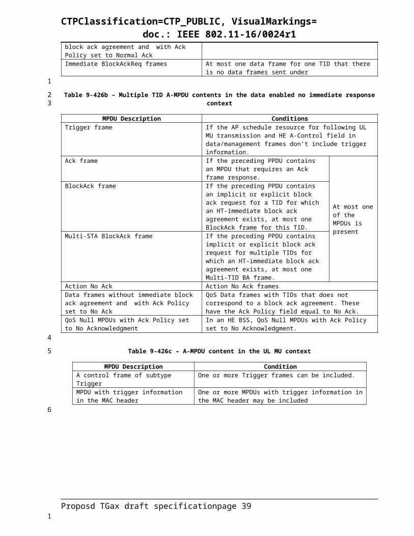
CTPClassification=CTP_PUBLIC, VisualMarkings=doc.: IEEE 802.11-16/0024r1
1.17.1.810.22.2.9 Truncation of TXOPInsert the following at the end of subclause 10.22.2.9:
An HE STA that receives a CF-End frame should not reset its NAV if:
— The CF-End did not originate from the STA’s associated BSS or any BSS of a multi-BSSID set that the STA’s associated BSS belongs to and the most recent NAV update was due to a PPDU originating from the STA’s associated BSS or any BSS of a multi-BSSID set that the STA’s associated BSS belongs to.
— The CF-End originated from the STA’s associated BSS or any BSS of a multi-BSSID set that the STA’s associated BSS belongs to and the most recent NAV update was not due to a PPDU originating from the STA’s associated BSS or any BSS of a multi-BSSID set that the STA’s associated BSS belongs to.
10.24Block acknowledgment (block ack)
1.17.2
1.17.3
1.17.4
1.17.5
1.17.6
1.17.7
1.17.8
1.17.9
1.17.10
10.24.10 GCR block ackInsert the following sentences at the end of 2nd paragraph of section 10.24.10.3:
The originator may send a MU-BAR frame (MU-BAR Trigger variant of UL-Trigger Frame) to one or more of the HE STAs that have a GCR block ack agreement for this group address. Upon reception of the BlockAck frame, an originator may send a MU-BAR frame to other one or more HE STAs that have a block ack agreement for this group address, and this process may be repeated multiple times.
Insert the following sentences at the end of 4th paragraph of section 10.24.10.3:
When HE STA receives a MU-BAR frame with User identifier field set to the AID of the HE STA, the HE STA shall transmit BlockAck frame in the indicated resource unit SIFS after the Trigger frame. The BlockAck frames acknowledge the HE STA’s reception status of the block of group addressed frames requested by the MU-BAR frame.
Insert the following sentences and a picture at the end of 5th paragraph of section 10.24.10.3:
Figure 10-12 (Example of a frame exchange with GCR block ack retransmission policy) shows another example of a frame exchange when the GCR block ack retransmission policy is used. The HE AP sends
Proposd TGax draft specification page 39
1
2
3
4
5678
9101112
13
14
15
16
17
18
19
20
21
22
23
24
25262728
29
30313233
34
3536
1

CTPClassification=CTP_PUBLIC, VisualMarkings=doc.: IEEE 802.11-16/0024r1
several A-MSDUs using the GCR block ack retransmission policy. The HE AP then sends a MU-BAR to group member 1 and 2 of the GCR group, waits for the BlockAck frames, and then sends a MU-BAR to group member 3. After receiving the BlockAck frame from GCR group member 3, the HE AP determines whether any A-MSDUs need to be retransmitted and sends additional A-MSDUs (some of which might be retransmissions of previous A-MSDUs) using the GCR block ack retransmission policy.
Figure 10-12 - Example of a frame exchange with GCR block ack retransmission policy
Change the following sentences in 6th paragraph of section 10.24.10.3:
After completing the BlockAckReq and BlockAck frame exchanges or the MU-BAR and BlockAck frame exchanges, the originator determines from the information provided in the BlockAck bitmap and from the missing BlockAck frames which, if any, A-MSDUs need to be retransmitted.
Change the following sentences in 7th paragraph of section 10.24.10.3
An originator adopting the GCR block ack retransmission policy for a GCR group address chooses a lifetime limit for the group address. The originator may vary the lifetime limit for the group address at any time and may use different lifetime limits for different GCR group addresses. The originator transmits and retries each A-MSDU until the appropriate lifetime limit is reached or until each one has been received by all group members to which a BlockAckReq frame or an MU-BAR frame has been sent, whichever occurs first.
Insert the following sentences at the end of 8th paragraph of section 10.24.10.3
An originator may also regularly send an MU-BAR frame with User identifier field set to AIDs of HE STAs that transmit the BlockAck frames and the Block Ack Starting Sequence Control subfield set to the Sequence Number field of the earliest A-MSDU of the GCR stream that has not been acknowledged by all group members and has not expired due to lifetime limits, in order to minimize buffering latency at receivers in the GCR group.
Change the following in 12th paragraph of section 10.24.10.3
If the beginning of such reception does not occur during the first slot time following a SIFS in case of a BlockAckReq frame or a [TBD IFS] in case of an MU-BAR, then the originator may perform error recovery by retransmitting a BlockAckReq frame or an MU-BAR PIFS after the previous BlockAckReq frame or an MU-BAR frame when both of the following conditions are met:
— The carrier sense mechanism (see 10.3.2.1 (CS mechanism)) indicates that the medium is idle at the TxPIFS slot boundary (defined in 10.3.7 (DCF timing relations)) after the expected start of a BlockAck frame, and
— The remaining duration of the GCR TXOP is longer than the total time required to retransmit the GCR BlockAckReq frame or an MU-BAR frame plus one slot time.
10.44Target wake time (TWT)
10.44.1 TWT overviewChange the 2nd paragraph of 9.44.1 as follows:
Proposd TGax draft specification page 40
12345
67
8
91011
12
131415161718
19
2021222324
25
26272829
303132
3334
35
36
37
1
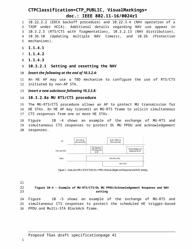
CTPClassification=CTP_PUBLIC, VisualMarkings=doc.: IEEE 802.11-16/0024r1
A TWT requesting STA communicates wake scheduling information to its TWT responding STA and the TWT responding STA devises a schedule and delivers TWT values to the TWT requesting STA when a TWT agreement has been established between them as described in 10.44.2 (Individual TWT agreements). When explicit TWT is employed, a TWT requesting STA wakes and performs a frame exchange and receives the next TWT information in a response from the TWT responding STA as described in 10.44.2.2 (Explicit TWT operation). When implicit TWT is used, the TWT requesting STA calculates the Next TWT by adding a fixed value to the current TWT value as described in 10.44.3 (Implicit TWT operation). An HE AP can additionally devise schedules and deliver TWT values to HE non-AP STAs without requiring that an individual TWT agreement has been established between them, as described in 10.44.4 (Broadcast TWT operation).
Insert a subclause heading after the 2nd paragraph of 10.44.1 (rest of dependent subclauses become dependent of this new subclause):
10.44.2 Individual TWT agreementsChange the 2 paragraphs (4th, 5th) of 9.44.1 as follows:
A STA with dot11TWTOptionActivated equal to true and that operates in the role of TWT requesting STA shall set the TWT Requester Support subfield to 1 in all S1G Capabilities or HE Capabilities elements that it transmits. A STA with dot11TWTOptionActivated equal to true and that operates in the role of TWT responding STA shall set the TWT Responder Support subfield to 1 in all S1G Capabilities or HE Capabilities elements that it transmits.
If the TWT Responder Support subfield of the S1G Capabilities or of the HE Capabilities element received from its associated AP is equal to 1, a non-AP STA with dot11TWTOptionActivated equal to true may transmit a TWT element to the AP with a value of Request TWT, Suggest TWT or Demand TWT in the TWT Command field and with the TWT Request field equal to 1.
Insert a new paragraph after the 9th paragraph as follows:
A STA that transmits a frame carrying a TWT element to an HE STA may set the Trigger subfield of the element to 1. Otherwise, the STA shall set the Trigger subfield to 0. In a TWT response, a Trigger field equal to 1 indicates a trigger-enabled TWT. The TWT responding STA of a trigger-enabled TWT agreement shall schedule for transmission a Trigger frame to the TWT requesting STA, as described in Error: Reference source not found (UL MU operation), within each TWT SP for that TWT agreement. The TWT responding STA that intends to transmit additional Trigger frames during a trigger-enabled TWT SP shall set the Cascade Indicaion field of the Trigger frame to 1 to indicate that it will transmit another Trigger frame within the same TWT SP. Otherwise, it shall set the Cascade Indicaion field to 0.
Insert a sentence at the end of the 10th paragraph of 10.44.1 as follows:
An HE STA that transmits a TWT element to another HE STA shall set the Implicit subfield of the element to 1 and the NDP Paging Indicator subfield of the element to 0.
Insert a sentence at the end of the 12th paragraph of 10.44.1 as follows:
A TWT requesting STA transmits a frame during a trigger-enabled TWT SP in response to a Trigger frame (see 25.5.2 (UL MU operation)).
Change the last 2 paragraphs of 10.44.1 as follows:
The Flow Type field in the TWT response that successfully set up a TWT agreement indicates the type of interaction between the TWT requesting STA and the TWT responding STA within each TWT SP for that TWT agreement. Flow Type field equal to 0 indicates an announced TWT. The TWT responding STA of an announced TWT agreement shall not transmit a frame, except for a Trigger frame within a trigger-enabled TWT SP, to the TWT requesting STA within a TWT SP until it has successfully received a PS-Poll frame or APSD trigger frame (see 10.2.2.5 (Power management with APSD)) from the TWT requesting STA. Flow Type field equal to 1 indicates an unannounced TWT. The TWT responding STA
Proposd TGax draft specification page 41
123456789
10
1112
13
14
1516171819
20212223
24
2526272829303132
33
3435
36
3738
39
40414243444546
1

CTPClassification=CTP_PUBLIC, VisualMarkings=doc.: IEEE 802.11-16/0024r1
of an unannounced TWT agreement may transmit a frame to the TWT requesting STA within a TWT SP before it has successfully received a frame from the TWT requesting STA.
An S1G TWT requesting STA indicates which single channel it desires to use as a temporary primary channel during a TWT SP by setting a single bit to 1 within the TWT Channel field of the TWT element, according to the mapping described for that field. An S1G TWT responding STA indicates which single channel the TWT requesting STA is permitted to use as a temporary primary channel during a TWT SP by setting a single bit to 1 within the TWT Channel field of the TWT element, according to the mapping described for that field. During a TWT SP, access to a channel which is not the primary channel of the BSS shall be performed according to the procedure described in 9.49 (Subchannel Selective Transmission (SST)). An HE STA indicates TBD .
1.17.11
10.44.3 Implicit TWT operationChange the 3rd paragraph of 9.44.4 of as follows:
A TWT requesting STA awake for an implicit TWT SP may transition to the doze state after AdjustedMinimumTWTWakeDuration time has elapsed from the TWT SP start time as identified by the TWT requesting STA. A TWT requesting STA awake for a trigger-enabled TWT SP may transition to the doze state if it receives a Trigger frame from the TWT responding STA with a Cascade Indicaion field equal to 0 that is not intended to it.
Insert a sentence at the end of the 4rd paragraph of 10.44.4 as follows:
An HE STA shall not generate BAT, TACK, or STACK frames.
Insert a new subclause, and dependent subclauses, at the end of 10.44 as follows:
10.44.4 Broadcast TWT operation10.44.4.1 GeneralA TWT scheduling STA is an HE AP with dot11TWTOptionActivated equal to true that includes a TWT element in the Beacon frame, and follows the rules described in 9.44.3.2 (Rules for TWT scheduling STA).
A TWT scheduled STA is an HE non-AP STA that:
— TBD: Declares support of being a TWT scheduled STA
— Receives a broadcast TWT element transmitted by an HE AP that is a TWT scheduling STA and,
— Has not negotiated any implicit TWT agreement with the HE AP as described in 10.44.2 (Individual TWT agreements).
A TWT scheduled STA follows the schedule provided by the TWT scheduling STA as described in Error:Reference source not found (Rules for TWT scheduled STA). A TWT scheduled STA can negotiate the TBTT and listen interval for Beacon frames it intends to receive as described in 10.44.4.3 (Negotiation of TBTT and listen interval).
An example of broadcast TWT operation is shown in Figure 10-13 (Example of broadcast TWT operation), where the AP is the TWT scheduling STA and STA 1 and STA 2 are the TWT scheduled STAs.
Proposd TGax draft specification page 42
12
3456789
10
11
12
13
1415161718
19
20
21
22
23
242526
27
28
29
3031
32333435
363738
1

CTPClassification=CTP_PUBLIC, VisualMarkings=doc.: IEEE 802.11-16/0024r1
AP
STA 1
STA 2
Beac
on
TWT
req.
TWT
resp
.
First TBTT Listen Interval
Beac
on
... ...
Optional TBTT Negotiation (First TBTT, Listen Interval)
TWT IE
PS-P
oll
PS-P
oll
M-B
A
Trigger-enabled TWT SP Unannounced TWT SP
DL MU PPDU
BABA
Doze Doze Doze Doze
Trig
ger
Beac
on
DozeDozeDozeDoze
TWT 1 TWT 2
Figure 10-13 - Example of broadcast TWT operation
10.44.4.2 Rules for TWT scheduling STAA TWT scheduling STA may include a TWT element in a Beacon frame scheduled at a TBTT (see 10.1.3.2 (Beacon generation in non-DMG infrastructure networks)). The TWT scheduling STA shall include one or more TWT parameter sets in the TWT element, and each TWT parameter set may indicate a periodic occurrence of TWTs. Each TWT parameter set specifies the TWT parameters of a broadcast TWT that are valid within a broadcast TWT SP.
The TWT scheduling STA sets the TWT parameters of each set as described below:
— The TWT scheduling STA shall set the Trigger field to 1 to indicate a trigger-enabled TWT. Otherwise, it shall set the Trigger field to 0. The TWT scheduling STA shall schedule for transmission a Trigger frame intended to one or more TWT scheduled STAs during a trigger-enabled TWT SP. The TWT scheduling STA that intends to transmit additional Trigger frames during a trigger-enabled TWT SP shall set the Cascade Indicaion field of the Trigger frame to 1 to indicate that it will transmit another Trigger frame within the same TWT SP. Otherwise, it shall set the Cascade Indicaion field to 0.
— The TWT scheduling STA shall set the TWT Flow Identifier field according to Table 8.248n1 (TWT Flow Identifier field for a broadcast TWT element). The TWT scheduling STA should only send frames that satisfy the TWT flow identifier recommendations listed in Table 8.248n1 (TWT Flow Identifier field for a broadcast TWT element) during the TWT SP(s).
— The TWT scheduling STA shall set the TWT field to the TSF[TBD X: TBD Y] time at which the first TWT is scheduled.
— The TWT scheduling STA shall include the value of the TWT wake interval in the TWT Wake Interval Exponent and TWT Wake Interval Mantissa fields for a periodic TWT. The TWT parameters are valid for each successive TWT of the periodic TWT.
— TBD
10.44.4.3 Negotiation of TBTT and listen intervalA TWT scheduled STA that intends to operate in power save mode (see 10.2.2.2 (STA Power Management modes)) may transmit a TWT request frame to the TWT scheduling STA that identifies the TBTT of the next Beacon frame the STA intends to receive and the interval between subsequent Beacon frames it intends to receive. The TWT request frame shall contain:
— The value of the requested first TBTT in the Target Wake Time field when the TWT Command field is Suggest TWT or Demand TWT.
— The value of the listen interval between consecutive TBTTs in the TWT Wake Interval Mantissa and TWT Wake Interval Exponent fields.
Proposd TGax draft specification page 43
12
3
45678
9
10111213141516
17181920
2122
232425
26
27
28293031
32333435
1

CTPClassification=CTP_PUBLIC, VisualMarkings=doc.: IEEE 802.11-16/0024r1
A TWT scheduling STA that receives a TWT request frame from a STA whose value of the TWT wake interval is equal to the STA’s listen interval shall respond with a TWT response frame that contains either Accept TWT or Reject TWT in the TWT Command field and, in the case of an Accept TWT, it shall also contain:
— The value of the allocated first TBTT in the Target Wake Time field, and
— The value of the listen interval between consecutive TBTTs in the TWT Wake Interval Mantissa and TWT Wake Interval Exponent fields.
After successfully completing the negotiation, the TWT scheduled STA may go to doze state until its TSF matches the next negotiated TBTT provided that the STA is in power save mode, and no other condition requires the STA to remain awake. The TWT scheduled STA shall be in the awake state to listen to Beacon frames transmitted at negotiated TBTTs and shall operate as described in in Error: Referencesource not found (Rules for TWT scheduled STA).
Either STA can tear down an established negotiation following the tear down procedure described in 10.44.8 (TWT Teardown).
25High Efficiency (HE) MAC specification
25.1 Introduction
25.2 Channel access
25.2.1 Updating two NAVsMandatory or optional support of two NAVs is TBD.
For the two NAVs maintained by a HE STA, one is identified as Intra-BSS NAV, and the second one is identified as regular NAV.
A STA that receives at least one valid frame in a PSDU and identifies the frame as Intra-BSS can update its Intra-BSS NAV with the information from any valid Duration field in the PSDU.
A STA that receives at least one valid frame in a PSDU and identifies the frame as Inter-BSS can update its regular NAV with the information from any valid Duration field in the PSDU.
A STA that receives at least one valid frame in a PSDU and cannot identify the frame as Intra-BSS or Inter-BSS can update its regular NAV with the information from any valid Duration field in the PSDU.
A STA that receives a valid HE-SIG-A in a HE PPDU and identifies the HE-SIG-A as Intra-BSS can update its Intra-BSS NAV with the information from the TXOP Duration field in the HE-SIG-A.
A STA that receives a valid HE-SIG-A in a HE PPDU and identifies the HE-SIG-A as Inter-BSS can update its regular NAV with the information from the TXOP Duration field in the HE-SIG-A.
When the received frame's RA is equal to the STA's own MAC address, the STA shall not update its Intra-BSS NAV or regular NAV with the information from the Duration field.
When a STA receives both a valid HE-SIG-A in a HE PPDU and a valid frame in the PSDU of the HE PPDU, the STA shall not update its Intra-BSS NAV or regular NAV with the information from the TXOP Duration field in the HE-SIG-A.
For all other received frames that are identified by the STA as Intra-BSS, the STA shall update its Intra-BSS NAV when the received value of the Duration field is greater than the STA's current Intra-BSS NAV value.
Proposd TGax draft specification page 44
1234
5
67
89
101112
1314
15
16
17
18
19
2021
2223
2425
2627
2829
3031
3233
343536
373839
1

CTPClassification=CTP_PUBLIC, VisualMarkings=doc.: IEEE 802.11-16/0024r1
For all other received frames that are identified by the STA as Inter-BSS or cannot be identified as Intra-BSS or Inter-BSS, the STA shall update its regular NAV when the received value of the Duration field is greater than the STA's current regular NAV value.
For all other received HE-SIG-As that are identified by the STA as Intra-BSS, the STA shall update its Intra-BSS NAV when the received value of the TXOP Duration field is greater than the STA's current Intra-BSS NAV value.
For all other received HE-SIG-As that are identified by the STA as Inter-BSS, the STA shall update its Inter-BSS NAV when the received value of the TXOP Duration field is greater than the STA's current regular NAV value.
25.3 Fragmentation
25.3.1 GeneralAn HE STA can dynamically fragment individually addressed MSDUs or MMPDUs and defragment received MPDUs as defined in this subclause, and using the fragmentation/defragmentation processes defined in 10.2.7 (Fragmentation/defragmentation overview) without being subject to the rules defined in that subclause.
25.3.2 Procedure at the originatorA dynamic fragment is an MPDU, the payload of which carries a portion of an MSDU or MMPDU, which generation follows the rules defined in 9.5 (Fragmentation), except for:
— Reception of dynamic fragments is not mandatory. An HE STA declares its capability of receiving dynamic fragments by setting the HE Fragmentation Support field of the HE Capabilities element it transmits to a nonzero value as described below.
— The length of each fragment is not required to be equal for all fragments. The length of each fragment may be of any nonzero value. Other conditions may be TBD.
An HE STA may transmit to a receiver STA an individually addressed (A)-MPDU that contains:
— One dynamic fragment of an MSDU or MMPDU in a VHT single MPDU if the receiver STA has indicated a nonzero value in the HE Fragmentation Support field of its HE Capabilities element
o The originator STA shall follow the rules defined in 9.13.8 (Transport of VHT single MPDUs) for generating the VHT single MPDU
— Up to one dynamic fragment for each MSDU in an A-MPDU if the receiver STA has indicated a value of 2 in the HE Fragmentation Support field of its HE Capabilities element
o The originator STA shall follow the rules defined in in 9.24.7 (HT-immediate block ack extensions) for generating the A-MPDU
— Up to four dynamic fragments for each MSDU in an A-MPDU if the receiver STA has indicated a value of 3 in the HE Fragmentation Support field of its HE Capabilities element
o The originator STA shall set the Fragment Number subfield of each MPDU to a value less than 4
o The originator STA shall follow the rules defined in 10.24.7 (HT-immediate block ack extensions) for generating the A-MPDU with the following exceptions:
The A-MPDU should contain MPDUs whose range of the Sequence Number subfields does not exceed 16. Other conditions may be TBD.
An HE STA shall not transmit a PSDU that contains dynamic fragments of an MSDU or MMPDU whose number is greater than the maximum number of fragments or that are carried in an A-MPDU format that
Proposd TGax draft specification page 45
123
456
789
10
11
12131415
16
1718
192021
2223
24
2526
2728
2930
3132
3334
3536
3738
3940
4142
1

CTPClassification=CTP_PUBLIC, VisualMarkings=doc.: IEEE 802.11-16/0024r1
is not supported by the receiver STA, as determined by the value of the HE Fragmentation Support field of the HE Capabilities element sent by the receiver STA.
25.3.3 Procedure at the receiverAn HE STA that transmits an HE Capabilities element with a nonzero value in the HE Fragmentation Support subfield shall set dot11DynamicFragmentation to true. Otherwise, the HE STA may set dot11DynamicFragmentation to false.
Defragmentation of dynamic fragments shall follow the rules defined in 10.6 (Defragmentation), except for:
— The receiver STA may support the concurrent reception of dynamic fragments of TBD number of MSDUs/MMPDUs under TBD conditions
NOTE— The receiver STA is still subject to the Receive Timer rules for each fo the MSDUs/MMPDUs as defined in 9.6 (Defragmentation).
Upon reception of a PSDU that carries one or more dynamic fragments, the receiver STA responds with:
— An Ack frame when the received fragment is contained in a VHT single MPDU that solicits the immediate response
o The receiver STA shall follow the rules defined in 10.3.2.9 (Ack procedure) for generating the Ack frame
— A BlockAck frame when the received fragments, up to one fragment for each MSDU, are contained in the A-MPDU that solicits the immediate response and is sent by an HE STA whose HE Fragmentation Support subfield in its HE Capabilities element is 2
o The receiver STA shall follow the rules defined in 10.24.7 (HT-immediate block ack extensions) for generating the BlockAck frame, except that the STA shall:
Set to 1 each bit of the Block Ack Bitmap field that corresponds to a Sequence Number subfield of a successfully received fragment contained in the soliciting A-MPDU
Update the corresponding block acknowledgement record when an MSDU that is received in fragments is successfully reconstructed (see 10.6 (Defragmentation)).
— A BlockAck frame when the received fragments, one or more fragments for each MSDU, are contained in an A-MPDU that solicits the immediate response and is sent by an HE STA whose HE Fragmentation Support subfield in its HE Capabilities element is 3
o The receiver STA shall follow the rules in 10.24.7.5 (Generation and transmission of BlockAck frames by an HT STA or DMG STA) for generating the BlockAck frame, except that the STA shall:
Set to 1 the Fragment Number subfield in the Block Ack Starting Sequence Control subfield of the BlockAck frame
Set to 1 each bit in location B of the Block Ack Bitmap field that corresponds to a successfully received fragment and shall set it to 0 otherwise, with B calculated as:B = SC – SSN, where SC and SSN are treated as 14-bit unsigned integersSC is the value of the Sequence Control subfield of an MPDU containing the fragment for which the receive status is indicated SSN is the value of the Starting Sequence Number subfield of the Block Ack Starting Sequence Control subfield of the BlockAck frame
Update the corresponding block acknowledgement record when an MSDU that is received in fragments is successfully reconstructed (see 9.6 (Defragmentation)).
Proposd TGax draft specification page 46
12
3
456
78
910
1112
13
1415
1617
181920
2122
232425
2627
282930
313233
3435
3637383940414243
4445
1

CTPClassification=CTP_PUBLIC, VisualMarkings=doc.: IEEE 802.11-16/0024r1
25.4 Block acknowledgement
25.4.1 Selection of BlockAck and BlockAckReq variantsAn HE STA may send a Multi-STA BlockAck frame in response to an HE trigger-based PPDU. A Multi-STA BlockAck frame contains one or more BA Information fields with one or more AIDs and one or more different TIDs. A Multi-STA BlockAck frame with BA Information for multiple AIDs shall have RA field set to the broadcast address.
An HE STA that supports Multi-STA BA shall examine each received Mulit-STA sent by an STA with which it has a BA agreement. On receiving such a Multi-STA BlockAck frame a STA performs the following for each BA Information field with its AID:
— If the ACK type field is 1 then the BA Start Sequence Control, TID and BA Bitmap of the BA information field are processed according the procedure given in 10.24.7.
— If the ACK type field is 0, the field indicates an ACK of either a single MPDU or all MPDUs carried in the eliciting PPDU that was transmitted by the STA.
25.5 MU operation
25.5.1 HE DL MU operation25.5.1.1 GeneralHE DL MU operation allows an AP to transmit simultaneously to one or more non-AP STAs in DL OFDMA, DL MU-MIMO or both.
An AP shall not transmit to a STA an HE MU PPDU with the HE-SIG-B allocating more than one RUs (see 25.3.9.8.3), unless the STA set the DL OFDMA Capable subfield of the HE Capabilities element to 1.
An AP shall not transmit to a STA a HE MU PPDU with the HE-SIG-B allocating spatial streams to more than one recipient STA, unless the STA set the DL MU MIMO Capable subfield of the HE Capabilities element to 1.
The transmission for all the STAs in an HE MU PPDU in either DL OFDMA or DL MU MIMO shall end at the same time, indicated by the L-SIG field as described in 26.3.9.5.
The padding procedure for each A-MPDU in an HE MU PPDU is the same as for an A-MPDU in a VHT PPDU and defined in 10.13.6 (A-MPDU padding for VHT PPDU).
25.5.1.2 HE MU PPDU payloadThe content of each individual A-MPDU in an HE MU PPDU is based on the rules specified in 10.13.1 (A-MPDU contents).
The frame type and address type (unicast, groupcast) of MPDUs may be different across A-MPDUs within a same HE MU PPPDU.
A groupcast frame in a groupcast RU of an HE MU PPDU shall not include information intended for a STA that is identified as the recipient of another RU in the same HE MU PPDU.
25.5.2 UL MU operation25.5.2.1 GeneralThe UL MU operation allows an AP to solicit immediate simultaneous response frames from one or more non-AP STAs. Non-AP STAs transmit their response frames in HE trigger-based PPDU format, in either UL MU OFDMA UL MU-MIMO, or both.
Proposd TGax draft specification page 47
1
2
3456
789
1011
1213
14
15
16
1718
192021
222324
2526
2728
29
3031
3233
3435
36
37
383940
1

CTPClassification=CTP_PUBLIC, VisualMarkings=doc.: IEEE 802.11-16/0024r1
An HE STA with dot11ULMUOFDMAOptionImplemented set to true shall set the UL MU OFDMA Capable subfield of the HE Calabilities element it transmits to 1; otherwise, the STA shall set it to 0.
An HE STA with dot11ULMUMIMOOptionImplemented set to true shall set the UL MU MIMO Capable subfield of the HE Calabilities element it transmits to 1; otherwise, the STA shall set it to 0.
A non-AP STA with dot11ULMUOFDMAOptionImplemented or dot11ULMUMIMOOptionImplemented equal to true is referred to as an UL MU capable STA.
25.5.2.2 Rules for soliciting UL MU frames25.5.2.2.1 GeneralAn AP shall not send to a STA a frame soliciting the transmission of a PPDU with the TXVECTOR parameter FORMAT set to HE_TRIG, unless the STA is UL MU Capable.
An AP may transmit a PPDU that elicits elicits an HE trigger-based PPDU from one or more UL MU capable STAs by including in the PPDU at least one of:
— A Trigger frame that includes one or more per-User Info field addressed to the recipient STA(s).
o For recipient STAs that are associated with the AP, the per-User Info field is addressed to a recipient STA if the value of the AID subfield of the Per-User Info field is equal to the AID of the STA.
o For recipient STAs that are not associated with the AP, TBD
— An “Trigger Information TBD contained in the MAC Header” of individually addressed MPDUs contained in the PPDU
The following two frames shall not be present at the same time in an A-MPDU
— A Trigger frame with a per-User Info field addressed to a STA
— an MPDU addressed to the same STA that includes “Trigger Information Field info in MAC header TBD”
If a Trigger frame is aggregsated with other frames in an A-MPDU, the Trigger frame shall be the first frame in the A-MPDU.
25.5.2.2.2 Allowed settings of the Trigger frame fieldsIf dot11MultiBSSIDActivated is true and at least two of the Trigger frame recipient STAs are associated with two different BSSIDs, then the TA shall be set to a common address TBD; in all other cases the TA shall be set to the BSSID of the AP to which all recipient STAs are associated.
An AP shall not set any subfields of the Commin Info field to a value that is not supported by all the recipient STAs of the Trigger frame.
An AP shall not set any subfields of a Per User Info field to a value that is not supported by the recipient STAs of the Per User Info field.
If a Trigger frame is transmitted in a broadcast RU of a HE MU PPDU, then the Trigger frame shall not include any Per User Info fields addressed to a STA that is identified as recipient of another RU or spatial stream of the same HE MU PPDU.
25.5.2.2.3 AP access procedures for UL MU operationAn UL OFDMA MPDU/A-MPDU is the acknowledgement of the Trigger frame. When the AP receives MPDU correctly from at least one STA indicated by trigger frame, the frame exchange initiated by the trigger frame is successful.
Proposd TGax draft specification page 48
12
34
56
7
8
910
1112
13
141516
17
1819
20
21
2223
2425
26
272829
3031
3233
343536
37
383940
1
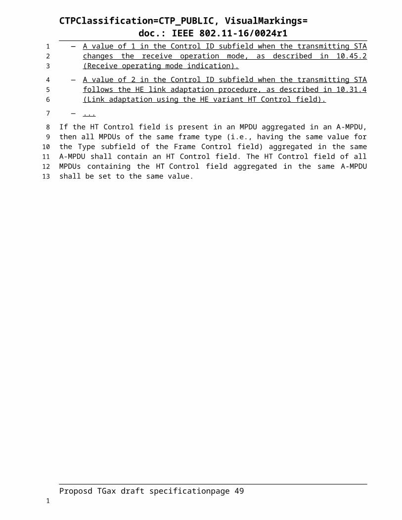
CTPClassification=CTP_PUBLIC, VisualMarkings=doc.: IEEE 802.11-16/0024r1
25.5.2.3 STA behaviorA STA shall not transmit an HE trigger-based PPDU unless is it explicitly enabled by an AP in one of the operation modes described in this section.
The inter frame space between a PPDU that contains a Trigger frame and the triggered HE trigger-based PPDU is SIFS.
A STA shall commence the transmission of an HE trigger-based PPDU at the SIFS time boundary after the end of a received PPDU, when all the following conditions are met
— The received PPDU contains a Trigger Frame with a Per User Info field addressed to the STA, or the PPDU contains an MPDU addressed to the STA which carries a “Trigger Information Field info in MAC header TBD”. The Per User Info field is addressed to a STA if the AID subfield is equal to the AID of the STA, if the STA is associated with the AP. If the STA is not associated with the AP, TBD.
— The UL MU CS Condition described in 25.5.2.4 (UL MU CS mechanism) indicates the medium is idle, or the CS Required subfield in a Trigger frame is 0.
A STA transmitting an HE trigger-based PPDU shall set the TXVECTOR parameter as follows:
— The L_LENGTH parameter shall be set to the value indicated by the L-SIG Length field of the eliciting Trigger frame or of the “Trigger Information Field info in MAC header TBD”.
— The CP_LTF_TYPE parameter shall be set to the value indicated by the CP-LTF subfield of the Common Info field of the eliciting Trigger frame
— The SIG-A_CONT parameter shall be set to the value indicated by the SIG-A subfield of the Common Info field of the eliciting Trigger frame [TBD, depending on how the TXVECTOR is defined we may spell out all the subfields of SIG-A]
— The DCM parameter shall be set to the value indicated by the DCM subfield of the per-User Info field of the eliciting Trigger frame
— The CODING_TYPE parameter shall be set to the value indicated by the Coding Type subfield of the Per User Info field of the eliciting Trigger frame
— The RU parameter shall be set to the value indicated by the RU Allocation field of the trigger frame
— The NSTS parameter shall be set to TBD
The MAC padding procedure is descried in 10.42.2.1.2
The content of each individual A-MPDU in an HE MU PPDU is based on the rules specified in 9.13.1 (A-MPDU contents) and the additional rules described in this clause.
If the Trigger Type value of a Trigger frame is not equal to 0, the STA shall include in the reponse A-MPDU at least one MPDU of the required type. If the STA does not have a frame of the required type, the STA should transmit QoS Null frame.NOTE--The frame type of MPDUs may be different across A-MPDUs within a same HE trigger-based PPPDU
25.5.2.4 UL MU CS mechanismThe ED-based CCA and virtual CS functions are used to determine the state of the medium if CS is required before responding to a received Trigger frame. ED-based CCA is described in and virtual CS is defined in 10.3.2.1 (CS mechanism).
When two NAVs are supported by a STA, if one or both of the NAVs are considered and the considered NAV’s counter is nonzero, then the virtual CS indicates busy. Otherwise, the virtual CS is idle.
Proposd TGax draft specification page 49
1
23
45
67
89
101112
1314
15
1617
1819
202122
2324
2526
2728
29
30
3132
333435
36
37
383940
4142
1

CTPClassification=CTP_PUBLIC, VisualMarkings=doc.: IEEE 802.11-16/0024r1
When only one NAV is supported by a STA, if the NAV is considered and the NAV counter is nonzero, then virtual CS is busy. Otherwise, the virtual CS is idle.
Note that the previous sentence is only needed if support for two NAVs is optional. Mandatory or optional support for two NAVs is still TBD.
A NAV is considered in virtual CS for a STA that is polled from a Trigger frame for UL MU transmission unless one of the following conditions is met:
— The NAV was set by a frame originating from the AP sending the Trigger frame
— The response generated by the STA contains an Ack frame or a BlockAck frame and the duration of the HE trigger-based PPDU is less than a TBD value
— The NAV was set by a frame originating from an intra-BSS STA
— The CS Required subfield in the Trigger frame is 0
— Other condition TBD
If the CS Required subfield in a Trigger frame is set to 1, the STA shall consider the status of the CCA (using Energy Detect) and the virtual carrier sense (NAV) before UL MU transmission in response to the Trigger Frame. In this case, the STA shall sense the medium using energy-detect (ED) after receiving the PPDU that contains the Trigger frame (i.e. during the SIFS time), and it shall perform the energy-detect (ED) at least in the subchannel that contains the STA’s UL allocation, where the sensed subchannel consists of either a single 20 MHz channel or multiple of 20 MHz channels. The STA may transmit an HE trigger-based PPDU when the 20 MHz channels containing the allocated UL RUs in the Trigger frame are considered idle; if the STA detects that the 20 MHz channels containing the allocated UL RUs are not all idle, then the STA shall not transmit anything in the allocated UL RUs.
If the CS Required subfield in a Trigger frame is set to 0, the STA may transmit an HE trigger-based PPDU without the carrier sense.
The AP shall set the CS Required subfield to 1 except under the following conditions:
— All HE trigger-based PPDU(s) solicited by the Trigger frame containing ACK/BA and the length of the HE trigger-based PPDU is below a TBD threshold.
— Other conditions are TBD.
25.5.2.5 HE buffer status feedback operation for UL MUThe buffer status report from HE STAs may be utilized to support the efficient UL MU operation. An AP may poll HE STAs for buffer status reports using the frame carrying the trigger information. The frame may be a broadcast Trigger frame, a unicast Trigger frame, a Trigger frame for random access, or a Data type of frame carrying the trigger information. An AP may request an HE STA to send its buffer status information by TBD indication in the Trigger frame or in the HE A-Control field in a Data type of frame. In this case, an AP may indicate TBD granularity of the Queue Size for an HE STA to report (signalling method TBD). Upon reception of the frame including the TBD indication in the Trigger frame or in the HE A-Control field, the HE STA may respond with the frame including the Queue Size subfield in a QoS Control field or TBD HE A-Control field. To report the buffer status for a given TID, an HE STA shall set the Queue Size subfield in a QoS Data or a QoS Null frame to the amount of queued traffic present in the output queue belonging to the TID.
25.5.2.6 UL OFDMA-based random accessUL OFDMA-based distributed random access is a random access mechanism for HE STAs that randomly select resource units (RUs) assigned by an AP for transmission of UL PPDUs. The HE AP indicates a TBD parameter in the Trigger frame for HE STAs to initiate random access following the Trigger frame transmission.
Proposd TGax draft specification page 50
12
34
56
7
89
10
11
12
131415161718192021
2223
24
2526
27
28
2930313233343536373839
40
41424344
1

CTPClassification=CTP_PUBLIC, VisualMarkings=doc.: IEEE 802.11-16/0024r1
25.5.2.6.1 Random access procedureIn this sub-section, the random access procedure is described with respect to UL OFDMA contention parameters. The procedure is also illustrated in Figure 25-14. An HE STA that uses the random access procedure maintains an internal counter termed as OBO counter. The OFDMA contention window (OCW) is an integer with an initial value of OCWmin. Other parameters for random access are TBD.
Figure 25-14 - Illustration of the UL OFDMA-based random access procedure
An HE AP indicates the value of OCWmin for the random access operation. The method of indication of the OCWmin value is TBD.
The random access procedure initiates with an HE STA receiving a Trigger frame for random access.
For an initial UL PPDU transmission, when an HE STA obtains the value of OCWmin from the HE AP, it shall set the value of OCW to the OCWmin and shall initialize its OBO counter to a random value in the range of 0 and OCWmin.
If the OBO counter for an HE STA is smaller than the number of RUs assigned to AID value TBD in a Trigger frame, then the HE STA shall decrement its OBO counter to zero. Otherwise, the HE STA decrements its OBO counter by a value equal to the number of RUs assigned to AID value TBD in a Trigger frame. For instance, as shown in Figure 25-14, HE STA 1 and HE STA 2 decrement their non-zero OBO counters by 1 in every RU assigned to AID value TBD for random access within the Trigger frame.
If the OBO counter for an HE STA is a zero value or if the OBO counter decrements to 0, it randomly selects any one of the assigned RUs for random access and transmits its UL PPDU in the selected RU. Otherwise, the STA resumes with its OBO counter in the next Trigger frame for random access.
25.5.3 HE MU cascading operationA TXOP can include both DL MU and UL MU transmissions.
A HE AP can initiate a cascading sequence of MU PPDUs in a TXOP, allowing alternating HE MU PPDUs and HE trigger-based PPDUs starting with a DL MU PPDU in the same TXOP, as illustrated in Figure 25-15.
t
DL MU PPDU UL MU PPDU(s)
xIFS
…
TXOP
…
Figure 25-15 - An example of cascading sequence of MU PPDUs
Proposd TGax draft specification page 51
1
2345
67
89
10
111213
141516171819
202122
23
24
252627
2829
1

CTPClassification=CTP_PUBLIC, VisualMarkings=doc.: IEEE 802.11-16/0024r1
The cascading sequence has only one DL transmitter. The cascading sequence may have different UL transmitters within each HE trigger-base PPDU. The cascading sequence may have a different set of transmitters in HE trigger-based PPDUs as compared to the DL HE MU PPDU that follows the HE trigger-based PPDUs within the same TXOP.
25.6 HE sounding protocolThe HE sounding protocol is initiated by an AP sending an NDP Announcement frame (TBD) followed by an HE NDP transmitted a SIFS after the end of the PPDU carrying the NDP Announcement (TBD).
An HE AP may use the Trigger frame to solicit HE beamforming feedback from a STA provided that the UL MU Capable field of the most recently received HE Capabilities element from that STA is 1 (see 25.5.2 (UL MU operation)).
An HE AP may solicit beamforming feedback from multiple STAs sequentially through SU transmission.
An example of the HE sounding protocol using MU operation to solicit feedback is shown in Figure 25-16.
Figure 25-16 – An example of the HE sounding protocol using MU operation
25.7 TWT operation
25.8 Receive operating mode
25.8.1 GeneralAn HE STA can change its operating mode setting either using the procedure described in 10.41 (Notificaion of operating mode changes), or the procedure describes in this subclause. Receive operating mode (ROM) indication is a procedure for a first HE STA to indicate the maximum operating channel width and the maximum number of spatial streams it can receive to a second HE STA.
When the first HE STA chooses to indicate its ROM setting, this can be signaled using the ROM subfield in the HE variant HT Control field sent in a frame of type Data. The ROM subfield is set to indicate that the first HE STA supports receiving frames with a bandwidth up to and including the value indicated by the Channel Width subfield and with a number of spatial streams up to and including the value indicated by the Rx NSS subfield (see [HE variant HT Control field]). The dot11ROMIOptionImplemented defines whether the HE AP implements the reception of the ROM setting and the AP transmits according to the ROM setting to the transmitter of the ROM setting. An HE AP shall set dot11ROMIOptionImplemented to true.
ROM indication allows an HE STA to adapt the maximum operating channel width or the maximum number of spatial streams it can receive. In doing so, an HE STA may save power by changing to a ROM setting that consumes less power, or by changing to a ROM setting that supports higher throughput operation. Unlike 11.41 (Notification of operating mode changes), ROM indication can be signaled in the
Proposd TGax draft specification page 52
1234
5
67
89
10
11
1213
1415
16
17
18
19202122
2324252627282930
31323334
1

CTPClassification=CTP_PUBLIC, VisualMarkings=doc.: IEEE 802.11-16/0024r1
MAC header of a Data frame as opposed to a management frame exchange. Hence, there is minimal impact on channel efficiency.
25.8.2 Rules for ROM indicationAn HE STA may transmit an individually address frame of type Data that contains the ROM subfield to indicate that the transmitting HE STA supports receiving frames with a bandwidth up to and including the value indicated by the Channel Width subfield and with a number of spatial streams up to and including the value indicated by the Rx NSS subfield of the ROM subfield.
The transmitting HE STA shall support for receiving frames with a bandwidth up to and including the value indicated by the Channel Width subfield and with a number of spatial streams up to and including the value indicated by the Rx NSS subfield of the ROM subfield indicated in the eliciting frame immediately after receiving a successful acknowledgement from the responding HE STA.
If there is a change to the current maximum operating channel width or the maximum number of spatial streams, the transmitting HE shall adjust to the most recently sent ROM settings within a time TBD [Outage Time] following the receipt of an immediate acknowledgement response. The transmitting HE STA shall support receiving frames with a bandwidth up to and including the most recent value indicated by the Channel Width subfield and with a number of spatial streams up to and including the most recent value indicated by the Rx NSS subfield of the ROM subfield.NOTE—In the event of transmission failures, the transmitting HE STA can attempt recovery procedure as defined in 9.19.2.4 (Multiple frame transmission in an EDCA TXOP), and can defer from changing to the new ROM settings indicated in the eliciting frame until a successful acknowledgement from the responding STA is received.
The responding HE STA shall use the value indicated by the Channel Width subfield most recently received from the transmitting HE STA as the current maximum operating channel width that the transmitting HE STA indicated as supported for receiving frames.
The responding HE STA shall use the value indicated by the Rx NSS subfield most recently received from the transmitting HE STA as the current maximum number of spatial streams that the transmitting HE STA indicated as supported for receiving frames.
The responding HE STA shall not transmit a subsequent PPDU to the transmitting HE STA that uses a bandwith or a number of spatial stream not indicated as currently supported by the transmitting HE STA.
If there is a change to the current maximum operating channel width or the maximum number of spatial stream that the transmistting STA is capable of receiving, the responding HE STA shall not sent any PPDU to the transmitting HE STA within a time TBD [Outage Time] following the transmission of an immediate acknowledgement response.
25.9 Spatial reuse operation
25.9.1 GeneralThe objective of the HE spatial reuse operation is to improve the system level performance and the utilization of the spectrum resources in dense deployment scenarios by early identification of signals from overlapping basic service sets (OBSSs) and interference management.
25.9.2 Color code based CCA rulesAn STA determines whether a detected frame is an inter-BSS or an intra-BSS frame by using BSS color or MAC address in the MAC header. The detected frame is intra-BSS frame if one of the following conditions is true:
— The BSS color in the detected PPDUis same as the BSS color announced by its associated AP,
— The RA or TA of the detected frame is same as the BSSID or its bandwidth signalling variant of its associated AP
Proposd TGax draft specification page 53
12
3
4567
89
1011
121314151617
181920
212223
242526
2728
29303132
33
34
353637
38
394041
42
4344
1

CTPClassification=CTP_PUBLIC, VisualMarkings=doc.: IEEE 802.11-16/0024r1
— Its associated AP is identified by TBD Multiple BSSID element and the RA or TA of the detected frame is same as one of the BSSID or its bandwidth signalling variant defined by TBD Multiple BSSID element
If the detected frame is an inter-BSS frame, under TBD condition, uses TBD OBSS PD level that is greater than the minimum receives sensitivity level.
A STA should regard an inter-BSS PPDU with a valid PHY header and that has receiving power/RSSI below the OBSS PD level used by the receiving STA and that meets additional TBD conditions, as not having been received at all (e.g., should not update its NAV), except that the medium condition shall indicate BUSY during the period of time that is taken by the receiving STA to validate that the PPDU is from an inter-BSS, but not longer than the time indicated as the length of the PPDU payload.
A STA should revise the NAV depending on TBD conditions at the recipient of the ongoing OBSS frame.
25.9.3 Adaptive CCA and transmit power controlWhen the color code based CCA rule is used, as described in Error: Reference source not found, an HE STA is allowed to adjust the OBSS_PD threshold in conjunction with transmit power control to improve the system level performance and the utilization of the spectrum resources.
To further improve the possibilities of spatial reuse, an STA is allowed to adjust the setting of one or more following parameters, CCA ED level, 802.11 signal detect CCA or TXPWR threshold values. The constraints on selecting threshold values are TBD.
25.10A-MPDU operation
25.10.1 GeneralA-MPDU operation for an HE PPDU is as defined in 10.13 (A-MPDU operation), except for A-MPDU padding, which is defined in 25.10.2 and except for an A-MPDU that includes QoS Data frames from from two or more different TSs, the rules for which are defined in 25.10.3.
25.10.2 A-MPDU paddingThe A-MPDU padding per each HE STA in an HE MU PPDU follows the same procedure as for VHT STA11ac procedure as defined in Section 10.13.6 (A-MPDU padding for VHT PPDU).
A non-AP STA that transmits an HE trigger-based PPDU shall construct the PSDU carried in the HE trigger-based PPDU as follows.
The STA computes the PSDU_LENGTH based on the TXVECTOR parameters.
The STA may add A-MPDU subframes to the A-MPDU contained in the PSDU provided that the following constraints are fullfilled:
— The A-MPDU content constraints (see 10.13.1 (A-MPDU contents)) for the intended recipient
— The Length limit constraints (see 9.7.1 (A-MPDU format) and 10.13.2 (A-MPDU length limit rules)) for the intended recipient
— The MPDU start spacing constraints (see 10.13.3 (Minimum MPDU Start Spacing field)) for the intended recipient
And provided that
— The A-MPDU subframes have a value greater than 0 in the MPDU Length field, or have a value 0 in the MPDU Length field and a value 0 in the EOF field.
— After incrementing the A-MPDU_Length with the length of each such added A-MPDU subframe, the relationship A-MPDU_Length ≤ PSDU_LENGTH is true.
Proposd TGax draft specification page 54
123
45
6789
10
11
12
131415
161718
19
20
212223
24
2526
2728
29
3031
32
3334
3536
37
3839
4041
1

CTPClassification=CTP_PUBLIC, VisualMarkings=doc.: IEEE 802.11-16/0024r1
Then, padding shall be added such that the resulting A-MPDU contains exactly PSDU_LENGTH octets as follows:
— First, while A-MPDU_Length < PSDU_LENGTH and A-MPDU_Length mod 4 != 0, add an octet to the final A-MPDU subframe's Padding subfield and increment A-MPDU_Length by 1.
— Then, while A-MPDU_Length + 4 < PSDU_LENGTH, add an EOF padding subframe to the EOF Padding Subframes field and increment A-MPDU_Length by 4.
— Finally, while A-MPDU_Length < PSDU_LENGTH, add an octet to the EOF Padding Octets subfield and increment A-MPDU_Length by 1.
The STA shall not add an A-MPDU subframe with EOF equal to 0 after any A-MPDU subframe with EOF set to 1. The STA shall not add an an A-MPDU subframe with EOF equal to 1 and with MPDU Length field equal to 0 before an A-MPDU subframe that contains a VHT single MPDU (see 10.13.7 (Setting the EOF field of the MPDU delimiter)).
25.10.3 A-MPDU with multiple TIDsAn HE STA with dot11AMPDUwithMultipleTIDOptionImplemented set to true shall set the A-MPDU with Multiple TIDs Capable subfield of the HE Calabilities element it transmits to 1; otherwise, the HE STA shall set it to 0.
An HE AP shall not send A-MPDU with multiple TIDs to an HE non-AP STA that associates with the AP, unless the HE non-AP STA is A-MPDU With Multiple TIDs capable.
An HE non-AP STA shall not send an A-MPDU with multiple TIDs to its associated HE AP, unless the HE AP is A-MPDU With Multiple TIDs capable.
In an HE MU PPDU, an HE STA may aggregate the frames in an A-MPDU with multiple TIDs as defined in Table 9-426a (Multiple TID A-MPDU contents in the data enabled immediate response context) or Table 9-426b (Multiple TID A-MPDU contents in the data enabled no immediate response context). An A-MPDU with multiple TIDs shall not be transmitted in an SU PPDU.
Multi-STA BlockAck frame shall be used to acknowledge the Multi-TID A-MPDU in MU PPDU. The value of TID field in Multi-STA BlockAck frame is TBD.
25.11TXVECTOR parameters STA_ID_LIST, UPLINK_FLAG and BSS_COLOR for an HE PPDU
Each element of the TXVECTOR parameter STA_ID_LIST identifies the STA or group of STAs that is the recipient of an RU in the HE MU PPDU. If an RU is intended for a single STA, then the STA_ID_LIST element for that RU is set to the STA’s AID. If an RU is intended for a group of STAs then the STA_ID_LIST element is set as follows:
— For a single BSS AP, if the RU is intended for all STAs in the BSS, the STA_ID_LIST element is set to 0;
— For a multiple BSS AP, if the RU is intended for all STAs in one of its BSSs, the STA_ID_LIST element is set to the group addressed AID assignment in the TIM according to the existing Multi-BSSID TIM operation;
— For a multiple BSS AP, if the RU is intended for all STAs on all its BSSs, the STA_ID_LIST element is set to 2047.
The Uplink Flag is carried in the TXVECTOR parameter UPLINK_FLAG of an HE SU PPDU, HE extended range SU PPDU, and HE MU PPDU and is set as follows:
— A STA transmitting an HE PPDU that is addressed to an AP shall set the TXVECTOR parameter UPLINK_FLAG to 1
Proposd TGax draft specification page 55
12
34
56
78
9101112
13
141516
1718
1920
21222324
2526
27
28
29303132
3334
353637
3839
4041
4243
1

CTPClassification=CTP_PUBLIC, VisualMarkings=doc.: IEEE 802.11-16/0024r1
— An AP transmitting an HE PPDU that is addressed to a non-AP STA shall set the TXVECTOR parameter UPLINK_FLAG to 0
— A STA transmitting an HE PPDU in a direct path to a (T)DLS peer STA, or to a member of an IBSS, shall set the TXVECTOR parameter UPLINK_FLAG to 0
NOTE—The (T) DLS peer STA or the member of an IBSS can identify that the HE PPDU is sent in a direct path from the To DS and From DS fields of the MAC header of its MPDU(s)
The TXVECTOR parameter UPLINK_FLAG is not present for HE trigger-based PPDUs.
The BSS Color is an identifier of the BSS and is used to assist a receiving STA in identifying the BSS from which a PPDU originates so that the STA can use the channel access rules as described in 9.X.Y (Spatial Reuse) or reduce power consumption as described in 25.13.1 (Intra-PPDU power save for HE non-AP STAs).
An HE AP shall select a value in the range 1 to TBD to include in the BSS Color subfield of the HE Operation elements that it transmits and shall maintain that single value of the BSS Color subfield for the duration of the existence of the BSS. An HE AP transmitting an HE PPDU shall set the TXVECTOR parameter BSS_COLOR to the value indicated in the BSS Color subfield of its HE Operation element.
A non-AP HE STA transmitting an HE PPDU shall set the TXVECTOR parameter BSS_COLOR to the value indicated in the BSS Color subfield of the HE Operation element received from the AP with which it is associated.
The virtual APs which are defined by TBD Multiple BSSID element shall select a same BSS Color.
25.12HE PPDU post FEC padding and packet extensionAn HE STA with dot11PPEThresholdsRequired set to false may set the PPE Thresholds Present subfield in HE Capabilities elements that it transmits to 0.
An HE STA with dot11PPEThresholdsRequired set to true shall set the PPE Thresholds Present subfield in HE Capabilities elements that it transmits to 1.
A STA that sets the PPE Thresholds Present subfield in HE Capabilities elements that it transmits to 1 shall indicate its minimum post-FEC padding and packet extension duration value per constellation, NSS and RU allocation by setting the subfields of the PPE Thresholds field according to 9.4.2.213 (HE Capabilities element) and using the corresponding values from dot11PPEThresholdsMappingTable.
A STA transmitting an HE PPDU to a receiving STA shall include a minimum post-FEC padding asetermined by the post-FEC padding a-factor (see 26.3.10 (Data field) and after including the post-FEC padding, the transmitting STA shall include a packet extension that yields a total post-FEC padding plus packet extension that corresponds to at least the value indicated in the HE Capabilities element received from the receiving STA.
25.13Power management
25.13.1 Intra-PPDU power save for HE non-AP STAsAn HE non-AP STA that is in awake state (see 11.2.2.2 (STA Power Management modes)) and has dot11IntraPPDUPowerSaveOptionActivated equal to true operates in intra-PPDU power save mode.
An HE non-AP STA that is in intra-PPDU power save mode may enter the doze state until the end of a received PPDU when one of the following conditions is met:
— The PPDU is an HE MU PPDU with:
o The value of the RXVECTOR parameter BSS_COLOR equal to the BSS color of the BSS with which the STA is associated and,
Proposd TGax draft specification page 56
12
34
56
7
89
1011
12131415
161718
19
20
2122
2324
25262728
2930313233
34
35
3637
3839
40
4142
1

CTPClassification=CTP_PUBLIC, VisualMarkings=doc.: IEEE 802.11-16/0024r1
o The value of the RXVECTOR parameter UL_FLAG is equal to 0 and,
o The values obtained from the RXVECTOR parameter STA_ID_LIST do not match the identifier of the STA or the broadcast identifier(s) intended for the STA
— The PPDU is an HE MU PPDU, HE SU PPDU, or HE extended range SU PPDU with:
o The value of the RXVECTOR parameter BSS_COLOR equal to the BSS color of the BSS with which the STA is associated and,
o The value of the RXVECTOR parameter UL_FLAG is equal to 1
— The PPDU is an HE trigger-based PPDU with:
o The value of the RXVECTOR parameter BSS_COLOR equal to the BSS color of the BSS with which the STA is associated
An HE STA that is in intra-PPDU power save mode and has entered doze state shall continue to operate its NAV timer and consider the medium busy during doze state and shall transition into awake state at the end of the PPDU.NOTE—The STA can contend for access to the medium immediately on the expiry of the NAV timer.
25.13.2 Power save with UL OFDMA-based random accessThis section illustrates the power save mechanisms for HE STAs using random access procedure (see 25.5.2.6.1).
An HE AP may indicate values of one or multiple Trigger frame start time(s) for random access in the Beacon. The power save operation with the indication of one value of Trigger frame start time in a Beacon for random access is shown in Figure 25-17.
Figure 25-17 - Illustration of Trigger frame (TF) Start Time in Beacon frame for power save operation with random access operation
When an HE STA receives a Beacon with the value of Trigger frame start time for random access, it may enter the doze state till the expiration of the value indicated in the Beacon.
If random acces is enabled by a sequence of Trigger frames, then all the Trigger frames in the sequence shall have the Cascade Indication field set to 1, except for the last Trigger frame in the sequence that shall have the Cascade Indication field set to 0.
An HE STA may use the value indicated in the Cascade Indication field in a Trigger frame to enter the doze state. If the OBO counter decrements to a non-zero value with the random access procedure in a Trigger frame with Cascade Indication field set to 0, it may enter the doze state immediately. If the OBO counter decrements to a non-zero value with the random access procedure in a Trigger frame with Cascade Indication field set to 1, it may remain awake for random access in the cascaded Trigger frame.
Proposd TGax draft specification page 57
1
23
4
56
7
8
910
111213
14
15
1617
181920
21
222324
2526
272829
3031323334
1

CTPClassification=CTP_PUBLIC, VisualMarkings=doc.: IEEE 802.11-16/0024r1
26High Efficiency (HE) PHY specification
26.1 Introduction
26.1.1 Introduction to the HE PHYClause 26 specifies the PHY entity for a high efficiency (HE) orthogonal frequency division multiplexing (OFDM) system. In addition to the requirements in Clause 26, an HE STA shall be capable of transmitting and receiving PPDUs that are compliant with the mandatory PHY specifications defined in Clause 20 and Clause 22.
The HE PHY is based on the VHT PHY defined in Clause 22, which in turn is based on the HT PHY defined in Clause 20, which in turn is further based on the OFDM PHY defined in Clause 18. The HE PHY extends the maximum number of users supported for downlink multi-user MIMO (MU-MIMO) transmissions to eight and provides support for downlink and uplink orthogonal frequency divisional multiple access (OFDMA) as well as for uplink MU-MIMO. Both downlink and uplink MU-MIMO transmissions are supported on portions of the PPDU bandwidth (on resource units greater than or equal to 106 tones) and in an MU-MIMO resource unit, there is support for up to eight users with up to four space-time streams per user with the total number of space-time streams not exceeding eight.NOTE—An HE SU PPDU includes individually addressed and group addressed transmissions.
The HE PHY provides support for 20 MHz, 40 MHz, 80 MHz and 160 MHz contiguous channel widths and support for 80+80 MHz non-contiguous channel width. Tones of one or more secondary channels in 80 MHz and 160 (80+80) MHz could be nulled when using OFDMA PPDU transmission. The modes of non-contiguous channel bonding are TBD. The non-contiguous channels within primary or secondary 80 MHz only exists at AP side.
The HE PHY provides support for 800 ns, 1600 ns, and 3200 ns guard interval durations.
The HE PHY provides support for 3.2 s (1x LTF), 6.4 s (2x LTF), and 12.8s (4x LTF) LTF symbol durations (symbol duration not including the guard interval).
The HE PHY data subcarriers are modulated using binary phase shift keying (BPSK), quadrature phase shift keying (QPSK), 16-quadrature amplitude modulation (16-QAM), 64-QAM, 256-QAM and 1024-QAM. Forward error correction (FEC) coding (convolutional or LDPC coding) is used with coding rates of 1/2, 2/3, 3/4 and 5/6.
An HE STA shall support the following Clause 26 features:
— Binary convolutional coding for RU sizes less than or equal to 242 tones (transmit and receive)
— LDPC as the only coding scheme for RU sizes of 484 tones, 996 tones (transmit and receive)
— LDPC when declaring support for at least one of HE 80/160/80+80 SU-PPDU bandwidths, or declaring support for more than 4 spatial streams (transmit and receive)
— A combination of 2x LTF with 0.8 µs GI duration on both LTF and data
— A combination of 2x LTF with 1.6 µs GI duration on both LTF and data
— A combination of 4x LTF with 3.2 µs GI duration on both LTF and data
An HE STA may support the following Clause 26 features:
— Other combinations of LTF durations and GI durations
— LDPC (transmit and receive) for RU sizes less than or equal to 242 tones
— LDPC (transmit and receive) when declaring support for less than or equal to 4 spatial streams
— Dual carrier modulation (transmit and receive)
Proposd TGax draft specification page 58
1
2
3
4567
89
101112131415
16
1718192021
22
2324
25262728
29
30
31
3233
34
35
36
37
38
39
40
41
1

CTPClassification=CTP_PUBLIC, VisualMarkings=doc.: IEEE 802.11-16/0024r1
NOTE--Once mandatory vs optional TBDs are decided, above text will have additions.
26.1.2 ScopeThe services provided to the MAC by the HE PHY consist of the following protocol functions:
a) A function that defines a method of mapping the PSDUs into a framing format (PPDU) suitable for sending and receiving PSDUs between two or more STAs.
b) A function that defines the characteristics and method of transmitting and receiving data through a wireless medium between two or more STAs. Depending on the PPDU format, these STAs support a mixture of HE, Clause 22 (Very High Throughput (VHT) PHY specification), Clause 20 (High Throughput (HT) PHY specification) and Clause 18 (Orthogonal frequency division multiplexing (OFDM) PHY specification) PHYs.
26.1.3 HE PHY functions26.1.3.1 GeneralThe HE PHY contains two functional entities: the PHY function, and the physical layer management function (i.e., the PLME). Both of these functions are described in detail in 26.3 (HE PHY) and 26.4 (HE PLME). The HE PHY service is provided to the MAC through the PHY service primitives defined in Clause 7 (PHY service specification). The HE PHY service interface is described in 26.2 (HE PHY service interface).
26.1.3.2 PHY management entity (PLME)The PLME performs management of the local PHY functions in conjunction with the MLME.
26.1.3.3 Service specification methodThe models represented by figures and state diagrams are intended to be illustrations of the functions provided. It is important to distinguish between a model and a real implementation. The models are optimized for simplicity and clarity of presentation; the actual method of implementation is left to the discretion of the HE-PHY-compliant developer.
The service of a layer is the set of capabilities that it offers to a user in the next higher layer. Abstract services are specified here by describing the service primitives and parameters that characterize each service. This definition is independent of any particular implementation.
26.1.4 HE PPDU formatsThe structure of the PPDU transmitted by an HE STA is determined by the TXVECTOR parameters as defined in Table 25-1 (TXVECTOR and RXVECTOR parameters).
The FORMAT parameter determines the overall structure of the PPDU:
— HE SU PPDU format (HE_SU) carries a single PSDU. With this format the HE-SIG-A field is not repeated. Support for the HE SU PPDU format is mandatory.
— HE MU PPDU format (HE_MU) carries one or more PSDUs to one or more users. It is similar to the SU format, except that an HE-SIG-B field is present. Support for the HE MU PPDU format is mandatory.
— HE extended range SU PPDU format (HE_EXT_SU) carries a single PSDU. It is similar to the SU format, except that the HE-SIG-A field is repeated. Support for the HE extended range SU PPDU format is TBD (mandatory or optional).
— HE trigger-based PPDU format (HE_TRIG) carries a single PSDU and is sent in response to a PPDU that carries a Trigger frame. The preamble format prior to the HE-STF field is identical to the HE SU PPDU. Support for the HE trigger-based PPDU format is TBD (mandatory or optional).
Proposd TGax draft specification page 59
1
23
45
6789
10
11
12
1314151617
18
19
20
21222324
252627
28
2930
31
3233
343536
373839
40414243
1
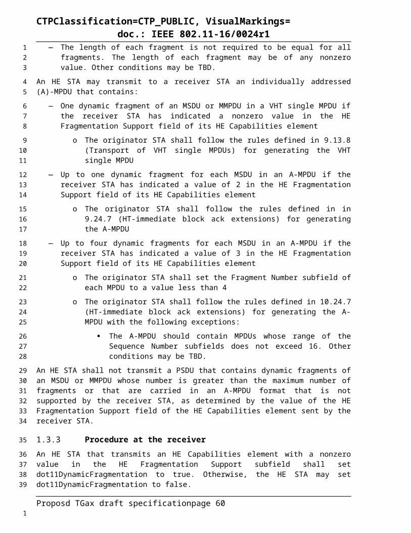
CTPClassification=CTP_PUBLIC, VisualMarkings=doc.: IEEE 802.11-16/0024r1
26.2 HE PHY service interace
26.2.1 Introduction
26.2.2 TXVECTOR and RXVECTOR parametersThe parameters in Table 26-4 (TXVECTOR and RXVECTOR parameters) are defined as part of the TXVECTOR parameter list in the PHY-TXSTART.request primitive and/or as part of the RXVECTOR parameter list in the PHY-RXSTART.indication primitive.
Table 26-4 - TXVECTOR and RXVECTOR parameters
Para
met
er
Condition Value
TX
VE
CT
OR
RX
VE
CT
OR
FOR
MA
T
Determines the format of the PPDU.Enumerated type:
NON_HT indicates Clause 18 (Orthogonal frequency division multiplexing (OFDM) PHY specification) or non-HT duplicate PPDU format. In this case, the modulation is determined by the NON_HT_MODULATION parameter.HT_MF indicates HT-mixed format.HT_GF indicates HT-greenfield format.VHT indicates VHT format.HE_SU indicates HE SU PPDU format.HE_MU indicates HE MU PPDU formatHE_EXT_SU indicates HE extended range SU PPDU formatHE_TRIG indicates HE trigger-based PPDU format
Y Y
PE_D
UR
ATI
ON
FORMAT is HE_SU or HE_MU or
HE_EXT_SU or HE_TRIG.
Determines the duration of PE field in an HE PPDU.Possible values are 0 µs, 4 µs, 8 µs, 12 µs and 16 µs.
BEA
M_C
HA
NG
E
FORMAT is HE_SU
Indicates beam change between pre-HE and HE modulated fields. 1 indicates that the beam is changed between the two portions.NOTE—BEAM_CHANGE shall be set to 1 if NSS > 2 or the PPDU is the first PPDU in a TXOP.
Otherwise Set to 1
Proposd TGax draft specification page 60
1
2
3
456
7
1
CTPClassification=CTP_PUBLIC, VisualMarkings=doc.: IEEE 802.11-16/0024r1
(To be added)
BSS
_CO
LOR FORMAT is HE_SU or
HE_MU or HE_EXT_SU or
HE_TRIG.
Set to a value of the AP’s choosing within the range 0 to TBD (see 25.11 (STA ID, Uplink Flag and BSS Color in HE PPDUs)).
Y Y
Otherwise Not present N N
UPL
INK
_FL
AG
FORMAT is HE_SU or HE_MU or
HE_EXT_SU
Set to 1 if the HE PPDU is addressed to an APSet to 0 otherwise (see 25.11 (STA ID, Uplink Flag and BSS Color in HE PPDUs)).
Y Y
Otherwise Not present N N
STA
_ID
_LIS
T
FORMAT is HE_MU Indicates the list of STA IDs for an HE MU PPDU (see 25.11 (STA ID, Uplink Flag and BSS Color in HE PPDUs)).
MU
Y
Otherwise Not present N N
NOTE 1—In the “TXVECTOR” and “RXVECTOR” columns, the following apply:
Y = Present;
N = Not present;
O = Optional;
MU indicates that the parameter is present once for an HE SU PPDU, HE extended range SU PPDU and HE trigger-based PPDU and present per user for an HE MU PPDU. Parameters specified to be present per user are conceptually supplied as an array of values indexed by u, where u takes values 0 to NUM_USERS-1.
26.3 HE PHY
26.3.1 Introduction
26.3.2 HE PPDU formatsFour HE PPDU formats are defined: HE SU PPDU, HE MU PPDU, HE extended range SU PPDU and HE trigger-based PPDU.
The format of the HE SU PPDU is defined as in Figure 26-18. This PPDU is used for SU transmission and in this format the HE-SIG-A field is not repeated.
L-STF L-LTF L-SIG RL-SIG HE-SIG-A HE-STF HE-LTF HE-LTF Data...8µs 8µs 4µs 4µs 8µs 4µs
Variable durations per HE-LTF symbol
PE
Figure 26-18 - HE SU PPDU format
Proposd TGax draft specification page 61
1
2
3
4
56
78
910
1

CTPClassification=CTP_PUBLIC, VisualMarkings=doc.: IEEE 802.11-16/0024r1
The format of the HE MU PPDU is defined as in Figure 26-19. This format is used for MU transmission that is not a response of a Trigger frame. An HE-SIG-B field is present in this format.
L-STF L-LTF L-SIG RL-SIG HE-SIG-A HE-STF HE-LTF HE-LTF Data...8µs 8µs 4µs 4µs 8µs 4µs
PEHE-SIG-B
4µs per symbol
Variable durations per HE-LTF symbol
Figure 26-19 - HE MU PPDU format
The format of the HE extended range SU PPDU is defined as in Figure 26-20. This format is used for SU transmission and in this format the HE-SIG-A field is repeated.
L-STF L-LTF L-SIG RL-SIG HE-SIG-A HE-STF HE-LTF HE-LTF Data...8µs 8µs 4µs 4µs 16µs 4µs
Variable durations per HE-LTF symbol
PE
Figure 26-20 - HE extended range SU PPDU format
The format of the HE trigger-based PPDU is defined as in Figure 26-21. This format is used for a transmission that is a response to a Trigger frame. The HE trigger-based PPDU format is identical to the HE SU PPDU format for the L-STF, L-LTF, L-SIG, RL-SIG, HE-SIG-A fields. The duration of the HE-STF field is 8 µs.
L-STF L-LTF L-SIG RL-SIG HE-SIG-A HE-STF HE-LTF HE-LTF Data...8µs 8µs 4µs 4µs 8µs 8µs
Variable durations per HE-LTF symbol
PE
Figure 26-21 - HE trigger-based PPDU format
The fields of the HE PPDU formats are summarized in Table 26-5.Table 26-5 - HE PPDU fields
Field DescriptionL-STF Non-HT Short Training fieldL-LTF Non-HT Long Training fieldL-SIG Non-HT SIGNAL fieldRL-SIG Repeated Non-HT SIGNAL field HE-SIG-A
HE Signal A field
HE-SIG-B HE Signal B field HT-STF HE Short Training fieldHE-LTF HE Long Training fieldData The Data field carrying the PSDU(s)PE Packet Extension field
The RL-SIG, HE-SIG-A, HE-SIG-B, HE-STF, HE-LTF, and PE fields exist only in HE PPDUs. In the HE NDP PPDU the Data field is not present. The number of OFDM symbols in the HE-LTF field, NHE-LTF, is 1, 2, 4, 6, or 8 and the duration of each symbol in the HE-LTF field is 3.2 µs, 6.4 µs, or 12.8 µs plus the GI duration. The HE-SIG-B field is present only in the HE MU PPDU. The duration of the PE field is determined by the TXVECTOR parameter PE_DURATION.
DL HE NDP is one DL HE sounding format.
The format of a HE NDP PPDU is shown in Figure 26-22.
Figure 26-22 - HE NDP PPDU format
Proposd TGax draft specification page 62
Packet ExtensionHE-LTFsHE-STFHE-SIG-ARL-SIGL-SIGL-LTFL-STF
12
3
45
67
89
10111213
1415
16
17
18
1920212223
24
25
26
2728
1

CTPClassification=CTP_PUBLIC, VisualMarkings=doc.: IEEE 802.11-16/0024r1
NOTE 1—The number of HE-LTF OFDM symbols, NHE-LTF in the NDP is a function of the total number of space-time streams NSTS as shown in Table 26-9.
NOTE 2—The combination of HE-LTF modes and GI duration is indicated in HE-SIG-A field.
NOTE 3—The duration of each HE-LTF OFDM symbol, THE-LTF, is defined in Table 26-6.
NOTE 4—The presence and duration of PE are TBD.
The HE NDP PPDU has the following properties:
— It uses the HE SU PPDU format but without the Data field— is an HE SU PPDU as implied by the value of L-Length field in L-SIG field
26.3.3 Transmitter block diagramThe generation of each field in a HE PPDU uses many of the following blocks:
a) pre-FEC PHY padding
b) Scrambler
c) FEC (BCC or LDPC) encoders
d) post-FEC PHY padding
e) Stream parser
f) Segment parser (for contiguous 160 MHz and noncontiguous 80+80 MHz transmissions)
g) BCC interleaver
h) Constellation mapper
i) DCM tone mapper
j) Pilot insertion
k) Replicate over multiple 20 MHz (if BW > 20 MHz)
l) Multiply by 1st column of PVHTLTF
m) LDPC tone mapper
n) Segment deparser
o) Space time block code (STBC) encoder
p) Cyclic shift diversity (CSD) per STS insertion
q) Spatial mapper
r) Inverse discrete Fourier transform (IDFT)
s) Cyclic shift diversity (CSD) per chain insertion
t) Guard interval (GI) insertion
u) Windowing
Figure 26-23 to Figure 26-30 show example transmitter block diagrams. The actual structure of the transmitter is implementation dependent.
In particular, Figure 26-23 shows the transmit process for the L-SIG, RL-SIG, and HE-SIG-A fields of a HE PPDU using one frequency segment, when the Beam Change subfield in HE-SIG-A field is set to 1. These transmit blocks are also used to generate the other pre-HE-SIG-B fields of the HE PPDU when the Beam Change subfield in HE-SIG-A field is set to 1, with the following exceptions applied:
— The BCC encoder and interleaver are not used when generating the L-STF and L-LTF fields.
Proposd TGax draft specification page 63
12
3
4
5
6
78
9
10
11
12
13
14
15
16
17
18
19
20
21
22
23
24
25
26
27
28
29
30
31
3233
34353637
38
1

CTPClassification=CTP_PUBLIC, VisualMarkings=doc.: IEEE 802.11-16/0024r1
— The BCC interleaver is not applied in the repeated HE-SIG-A symbols (i.e. the 2 nd and the 4th
OFDM symbols of HE-SIG-A field) in the HE extended range SU PPDU.
B
CC
Enc
oder
BC
C In
terle
aver
Con
stel
latio
n M
appe
r
IDFT
Insert GI and
Window
Analog and RF
CSD per
chain
CSD per
chain
Insert GI and
Window
Insert GI and
Window
Analog and RF
Analog and RF
Single Spatial Stream
NTX Transmit Chains...
Dup
licat
e ov
er m
ultip
le20
MH
z if
BW
> 2
0 M
Hz
Figure 26-23 - Transmitter block diagram for the L-SIG, RL-SIG and HE-SIG-A fields when the Beam Change field is 1
Figure 26-24 shows the transmit process for the L-SIG, RL-SIG, and HE-SIG-A fields of a HE PPDU using one frequency segment, when the Beam Change subfield in HE-SIG-A field is set to 0. These transmit blocks are also used to generate the other pre-HE-SIG-B fields of the HE PPDU when the Beam Change subfield in HE-SIG-A field is set to 0, with the following exceptions:
— The BCC encoder and interleaver are not used when generating the L-STF and L-LTF fields.
— The BCC interleaver is not applied in the repeated HE-SIG-A field OFDM symbols (i.e., the 2 nd
and the 4th OFDM symbols of HE-SIG-A field) in the HE extended range SU PPDU.
Figure 26-24 – Transmitter block diagram for the L-SIG, RL-SIG and HE-SIG-A fields when the Beam Change field is 0
Figure 26-25 shows the transmit process for the HE-SIG-B field of an HE MU PPDU using one frequency segment. This block diagram is for transmitting HE-SIG-B in one 20 MHz subchannel. Refer
Proposd TGax draft specification page 64
12
345
6789
10
1112
13
141516
1718
1

CTPClassification=CTP_PUBLIC, VisualMarkings=doc.: IEEE 802.11-16/0024r1
to 26.3.9.8.1 for the methods of transmitting HE-SIG-B in 40 MHz, 80 MHz and 160 MHz. The DCM tone mapper is applied only if the DCM indication in HE-SIG-A field is set to 1. (TBD: MCS0-DCM)
BC
C E
ncod
er
BC
C In
terle
aver
Con
stel
latio
n M
appe
r
IDFT
Insert GI and
Window
Analog and RF
CSD per
chain
CSD per
chain
Insert GI and
Window
Insert GI and
Window
Analog and RF
Analog and RF
Single Spatial Stream
NTX Transmit Chains
...
DC
M T
one
Map
per
Pre
-FE
C P
HY
Pad
ding
Figure 26-25 - Transmitter block diagram for the HE-SIG-B field
Figure 26-26 shows the transmitter blocks used to generate the Data field of a single user HE transmission within a 26-, 52-, 106-, or 242-RU with BCC encoding for a single frequency segment when the number of spatial stream is less than or equal to 4. This also includes the SU transmission in an RU that is part of a downlink or uplink OFDMA PPDU, and a transmission from one STA that is part of an UL MU-MIMO transmission in current RU. The STBC block may be applied only for single spatial stream and only when DCM is not applied. The DCM tone mapper is applied only when the DCM indication for the RU is set to 1. A subset of these transmitter blocks consisting of the constellation mapper and CSD blocks, as well as the blocks to the right of, and including, the spatial mapping block, are also used to generate the HE-LTF fields. This is illustrated in Figure 26-46. A subset of these transmitter blocks consisting of the constellation mapper and CSD blocks, as well as the blocks to the right of, and including, the spatial mapping block, are also used to generate the HE-STF field. (TBD: MCS0-DCM). This figure also applies to the data field with BCC encoding in a HE trigger-based PPDU.
Pre
-FE
C P
HY
P
addi
ng
Scr
ambl
er
BC
C
Inte
rleav
er
CSD per STS
CSD per STS
Stre
am P
arse
r
Con
stel
latio
n m
appe
r
STB
C (F
or o
ne s
patia
l stre
am o
nly)
Spa
tial a
nd F
requ
ency
Map
ping
......
BC
C E
ncod
er
BC
C
Inte
rleav
erB
CC
In
terle
aver
Con
stel
latio
n m
appe
rC
onst
ella
tion
map
per
DC
M T
one
Map
per
DC
M T
one
Map
per
DC
M T
one
Map
per
IDFTInsert GI
and Window
Analog and RF
IDFTInsert GI
and Window
Analog and RF
IDFTInsert GI
and Window
Analog and RF
...
NTX Transmit ChainsNSTS (≤4) Space-Time Streams
NSS Spatial Streams
Pos
t-FE
C P
HY
P
addi
ng
Figure 26-26 - Transmitter block diagram for the Data field of an HE SU transmission in a 26-, 52-, 106- or 242-RU with BCC encoding
Figure 26-27 shows the transmitter blocks used to generate the Data field of a single user HE transmission within a 26-, 52-, 106-, 242-, 484-, or 996-RU with LDPC encoding for a single frequency segment. This
Proposd TGax draft specification page 65
12
34
56789
10111213141516
171819
2021
1

CTPClassification=CTP_PUBLIC, VisualMarkings=doc.: IEEE 802.11-16/0024r1
also includes the SU transmission in an RU that is part of a downlink or uplink OFDMA PPDU, and a transmission from one STA that is part of an UL MU-MIMO transmission in current RU. The STBC block may be applied only for single spatial stream and only when DCM is not applied. The DCM tone Mapper is applied only when the DCM indication for the RU is set to 1. (TBD: MCS0-DCM) This figure also applies to the data field with LDPC encoding in a HE trigger-based PPDU.
Figure 26-27 - Transmitter block diagram for the Data field of an HE SU transmission in 26-, 52-, 106-, 242-, 484- or 996-RU with LDPC encoding
Figure 26-28 shows the transmitter blocks used to generate the Data field of a HE downlink MU-MIMO transmission within a 106-, 242-, 484-, or 996-RU with LDPC encoding. This also includes the downlink MU-MIMO transmission in an RU that is part of a downlink or uplink OFDMA PPDU.
Figure 26-28 - Transmitter block diagram for the Data field of an HE downlink MU-MIMO transmission in 106-, 242-, 484- or 996-RU with LDPC encoding
Proposd TGax draft specification page 66
12345
678
91011
121314
1

CTPClassification=CTP_PUBLIC, VisualMarkings=doc.: IEEE 802.11-16/0024r1
Figure 26-29 shows the transmitter blocks used to generate the Data field of a single-user HE transmission in 160 MHz with LDPC encoding.
Interleaver
Constellation mapper
Constellation mapper
DCM tone mapper
Stre
am P
arse
r
Seg
men
tP
arse
rS
egm
ent
Par
ser
LDPC tone mapper
LDPC tone mapper
Constellation mapper
CSDper STS
STB
C (F
or O
ne S
patia
l Stre
am O
nly)
Constellation mapper
Spa
tial M
appi
ng
DCM tone mapper
DCM tone mapper
LDPC tone mapper
LDPC tone mapper
IDFTInsert GI
and Window
Analog and RF
IDFTInsert GI
and Window
Analog and RF
Segment Deparser
Segment Deparser
Pre
-FE
C P
HY
P
addi
ng
Scr
ambl
er
LDP
C E
ncod
er
Pos
t-FE
C P
HY
P
addi
ng
CSDper STS
Figure 26-29 - Transmitter block diagram for the Data field of an HE SU PPDU in 160 MHz with LDPC encoding
Figure 26-30 shows the transmitter blocks used to generate the Data field of a single-user HE transmission in 80+80 MHz with LDPC encoding.
Interleaver
CSDper STS
STB
C
Spa
tial M
appi
ng
Constellation mapper
Constellation mapper
Pre
-FE
C P
HY
P
addi
ng
Scr
ambl
er
Stre
am P
arse
r
LDP
C E
ncod
er
Seg
men
tP
arse
rS
egm
ent
Par
ser
LDPC tone mapper
CSDper STS
STB
C (F
or O
ne S
patia
l Stre
am O
nly)
Spa
tial M
appi
ng
Constellation mapper
Constellation mapper
LDPC tone mapper
LDPC tone mapper
IDFTInsert GI
and Window
Analog and RF
IDFTInsert GI
and Window
Analog and RF
IDFTInsert GI
and Window
Analog and RF
IDFTInsert GI
and Window
Analog and RF
Pos
t-FE
C P
HY
P
addi
ng
DCM tone mapper
DCM tone mapper
DCM tone mapper
CSDper STS
Figure 26-30 - Transmitter block diagram for the Data field of an HE SU PPDU in 80+80 MHz with LDPC encoding
Proposd TGax draft specification page 67
12
345
67
89
10
1
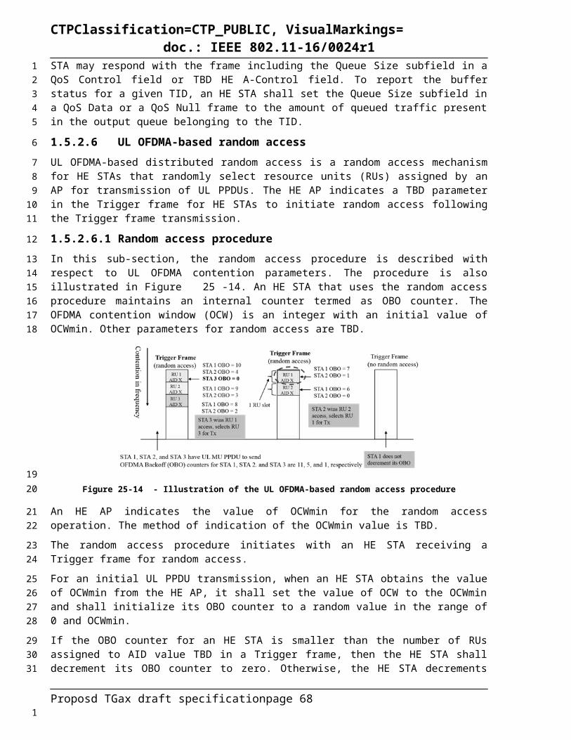
CTPClassification=CTP_PUBLIC, VisualMarkings=doc.: IEEE 802.11-16/0024r1
26.3.4 Overview of the PPDU encoding process
26.3.5 HE modulation and coding schemes (HE-MCSs)The HE-MCS is a value that determines the modulation and coding used in the HE-SIG-B field and the Data field of the PPDU. It is a compact representation that is carried in the HE-SIG-A field for the HE-SIG-B field in an HE MU PPDU and for the Data field in an HE SU PPDU and HE extended range SU PPDU and carried in the HE-SIG-B field for the Data field in an HE MU PPDU. Rate-dependent parameters for the full set of HE-MCSs are shown in Table 25-x (HE-MCSs for TBD mandatory/optional 26-tone RU, NSS = 1) to Table 25-y (HE-MCSs for optional non-OFDMA 160 MHz and 80+80 MHz, NSS = 8) (in 26.5 (Parameters for HE-MCSs)). These tables give rate-dependent parameters for HE-MCSs with indices 0 to 11, with number of spatial streams from 1 to 8, RU options of 26-tone, 52-tone, 106-tone, 242-tone, 484-tone and 996-tone, and bandwidth options of 20 MHz, 40 MHz, 80 MHz, and either 160 MHz or 80+80 MHz. HE-MCSs with indices 10 and 11 (1024-QAM) are optionally applied to the Data field of an HE PPDU with RUs equal to or larger than 242-tone. The HE extended range SU PPDU can only be transmitted with MCS0, MCS1, MCS2 and only with 1 spatial stream on the primary 20 MHz channel.
DCM is an optional modulation scheme used for the HE-SIG-B field and the Data field in an HE PPDU. It is indicated in the HE-SIG-A field for the HE-SIG-B field in an HE MU PPDU and for the Data field in HE SU PPDU, HE trigger-based PPDU and HE extended range SU PPDU and indicated in the HE-SIG-B field for the Data field in an HE MU PPDU. It is only applied for the HE-MCSs with indices 0, 1, 3 and 4.
26.3.6 Timing related parametersRefer to Table 20-6 and Table 22-5 (Timing-related constants) for timing-related parameters for non-HE PPDU formats.
Table 26-6 defines the timing-related parameters for HE PPDU formats.Table 26-6 – Timing related constants
Parameter Values Description312.5 kHz Subcarrier frequency spacing for the pre-HE portion.
78.125 kHz Subcarrier frequency spacing for the HE portion.
TDFT,Pre-HE 3.2 µs IDFT/DFT period for the pre-HE portion.TDFT,HE 12.8 µs IDFT/DFT period for the HE portion.TGI,Pre-HE 0.8 µs Guard interval duration for the legacy preamble, RL-
SIG, HE-SIG-A and HE-SIG-BTGI,HE-LTF TGI1,Data, TGI2,Data or TGI4,Data depending on the GI
used for dataGuard interval duration for the HE-LTF field, same as TGI,Data
TGI,Data TGI1,Data, TGI2,Data or TGI4,Data depending on the GI used for data
Guard interval duration for the HE-Data field
TGI1,Data 0.8 µs Base guard interval duration for the HE-Data field.TGI2,Data 1.6 µs Double guard interval duration for the HE-Data field. TGI4,Data 3.2 µs Quadruple guard interval duration for the HE-Data field. TSYM1 13.6 µs = TDFT,HE + TGI1.Data = 1.0625 × TDFT.HE Normal GI symbol intervalTSYM2 14.4 µs = TDFT,HE + TGI2.Data = 1.125 × TDFT,HE Double GI symbol intervalTSYM4 16 µs = TDFT,HE + TGI4.Data = 1.25 × TDFT,HE Quadruple GI symbol intervalTSYM TSYM1,TSYM2, or TSYM4 depending on the GI used
(see Table xx-x (Tone scaling factor and guard interval duration values for PHY fields))
Symbol interval
TL-STF 8 µs = 10 x TDFT, Pre-HE /4 Non-HT Short Training field durationTL-LTF 8 µs = 2 x TDFT,Pre-HE + TGI2,Data Non-HT Long Training field durationTL-SIG 4 µs Non-HT SIGNAL field durationTRL-SIG 4 µs Repeated non-HT SIGNAL field durationTHE-SIG-A 8 µs = 2 × 4 µs HE-SIG-Afield duration in an HE SU PPDU, HE MU
PPDU and HE trigger-based PPDU
Proposd TGax draft specification page 68
1
2
3456789
101112131415
16171819
20
2122
23
24
1

CTPClassification=CTP_PUBLIC, VisualMarkings=doc.: IEEE 802.11-16/0024r1
Parameter Values DescriptionTHE-SIG-A-R 8 µs or 16 µs (TBD) HE-SIG-A field duration in an HE extended range SU
PPDUTHE-STF-T 8 µs = 5 × 1.6 µs HE-STF field duration for an HE trigger-based PPDUTHE-STF-NT 4 µs = 5 × 0.8 µs HE-STF field duration for an HE SU PPDU, HE
extended range SU PPDU and HE MU PPDUTHE-LTF THE-LTF-1X , THE-LTF-2X or THE-LTF-4X depending upon
the LTF duration used Duration of each HE-LTF field OFDM symbol without GI
THE-LTF-1X 3.2 µs Duration of each 1x HE-LTF OFDM symbol without GITHE-LTF-2X 6.4 µs Duration of each 2x HE-LTF OFDM symbol without GITHE-LTF-4X 12.8 µs Duration of each 4x HE-LTF OFDM symbol without GITHE-LTF,SYM sum of THE-LTF and TGI,HE-LTF Duration of each HE-LTF OFDM symbol including GITHE-SIG-B 4 µs = TDFT,Pre-HE + TGI,Pre-HE Duration of each HE-SIG-B field OFDM symbolTPE 0, 4 µs, 8 µs, 12 µs, 16 µs depending on actual
extension duration usedDuration of the Packet Extension field
Nservice 16 Number of bits in the SERVICE fieldNtail 6 Number of tail bits per BCC encoderTSYML 4 µs Symbol duration including GI prior to the HE-STF field
Table 26-7 defines tone allocation related parameters for a non-OFDMA HE PPDU.Table 26-7 - Tone allocation related constants for Data field in a non-OFDMA HE PPDU
Parameter CBW20 CBW40 CBW80 CBW80+80 CBW160 Description
NSD 234 468 980 980 1960 Number of complex data numbers per frequency segment
NSP 8 16 16 16 32 Number of pilot values per frequency segment
NST 242 484 996 996 1992 Total number of subcarriers per frequency segment
NSR 122 244 500 500 1012 Highest data subcarrier index per frequency segment
NSeg 1 1 1 2 1 Number of frequency segmentsNDC 3 5 5 5 23 Number of null tones at DC per segment
NGuard,Left 6 12 12 12 12 Number of guard tones at the lower side of the spectrum
NGuard,Right 5 11 11 11 11 Number of guard tones at the higher end of the spectrum
NOTE: NST = NSD + NSP
Table 26-8 defines tone allocation related parameters for an OFDMA HE PPDU.Table 26-8 - Tone allocation related constants for RUs in an OFDMA HE PPDU
ParameterRU Size (Tones)
Description26 52 106 242 484 996
NSD 24 48 102 234 468 980 Number of complex data numbers per RU
NSP 2 4 4 8 16 16 Number of pilot values per RU
NST 26 52 106 242 484 996 Total number of subcarriers per RU
NOTE: NST = NSD + NSP
Table 26-9 defines parameters used frequently in Clause 26.Table 26-9 - Frequently used parameters
Symbol Explanation
NCBPS, NCBPS,r,u Number of coded bits per symbol at r-th RU for user u, r = 0, …, NRU – 1, u = 0, ..., Nuser,r – 1.For an HE SU PPDU, NCBPS = NCBPS,0,0
For an HE MU PPDU, NCBPS is undefined
Proposd TGax draft specification page 69
1
2
3
4
5
6
7
1

CTPClassification=CTP_PUBLIC, VisualMarkings=doc.: IEEE 802.11-16/0024r1
NCBPSS, NCBPSS,r,u Number of coded bits per symbol per spatial stream.For the Data field, NCBPSS,r,u equals the number of coded bits per symbol per spatial stream at r-th RU for user u, r = 0, …, NRU-1, u = 0, ..., Nuser,r–1.For the Data field of an HE SU PPDU, NCBPSS = NCBPSS,0,0
For the Data field of an HE MU PPDU, NCBPSS is undefined
NDBPS, NDBPS,r,u Number of data bits per symbol at r-th RU for user u, r = 0, …, NRU – 1, u = 0, ..., Nuser,r – 1.For an HE SU PPDU, NDBPS = NDBPS,0,0
For an HE MU PPDU, NDBPS is undefined
NBPSCS, NBPSCS,r,u Number of coded bits per subcarrier per spatial stream at r-th RU for user u, r = 0, …, NRU – 1, u = 0, ..., Nuser,r – 1.For an HE SU PPDU, NBPSCS = NBPSCS,0,0
For an HE MU PPDU, NBPSCS is undefined
NRX Number of receive chains
NRU For pre-HE modulated fields, NRU = 1. For HE modulated fields, NRU represents the number of RUs in the transmission (equal to the TXVECTOR parameter NUM_RUS).
Nuser,r For pre-HE modulated fields, Nuser,r = 1. For HE modulated fields, Nuser,r represents the number of users at r-th RU in the transmission (summing over all RUs equals to the TXVECTOR parameter NUM_USERS_TOTAL).
Nuser_total For pre-HE modulated fields, Nuser_total = 1. For HE modulated fields, Nuser_total represents the number of users in the transmission (equal to the TXVECTOR parameter NUM_USERS_TOTAL).
NSTS, NSTS,r,u For pre-HE modulated fields, NSTS,r,u = 1 (see NOTE 2). For HE modulated fields, NSTS,r,u the number of space-time streams at r-th RU for user u, u = 0,…, Nuser,r – 1. In case of STBC, NSTS,r,u = 2
For an HE SU PPDU, NSTS = NSTS,0,0
For an HE MU PPDU, NSTS=max r=0N RU−1 N STS, r ,total
NSTS,r,total For HE modulated fields, NSTS,r,total is the total number of space-time streams at the r-th RU in a PPDU.
N STS ,r ,total= ∑u=0
Nuser ,r−1
N STS, r ,u
For pre-HE modulated fields, NSTS,r,total is undefined.
Note that NSTS,r,total = NSTS for an HE SU PPDU.
NSS, NSS,r,u Number of spatial streams. For the Data field, NSS,r,u is the number of spatial streams at r-th RU for user u, u = 0,…,Nuser,r – 1
For the Data field of an HE SU PPDU, NSS = NSS,0,0
For the Data field of an HE MU PPDU,N SS=maxr=0NRU−1 N SS ,r , total
NSS,r,total For HE modulated fields, NSS,r,total is the total number of spatial streams at r-th RU in a PPDU.
N SS , r , total= ∑u=0
N user,r−1
NSS , r , u
For pre-HE modulated fields, NSS,r,total is undefined.
Note that NSS,r,total = NSS for an HE SU PPDU.
Proposd TGax draft specification page 701
CTPClassification=CTP_PUBLIC, VisualMarkings=doc.: IEEE 802.11-16/0024r1
NTX Number of transmit chains
NES, NES,r,u The number of BCC encoders. This parameter should be 1 in all BCC cases in 11ax.
For a Data field encoded using BCC, NES,r,u is the number of BCC encoders at r-th RU for user u, u = 0,…, Nuser,r – 1.
For the Data field encoded using LDPC, NES= 1 for an HE SU PPDU and NES,r,u = 1 for an HE MU PPDU at r-th RU for user u, u = 0, …Nuser,r – 1.
For the Data field of an HE SU PPDU, NES = NES,0,0
For the Data field of an HE MU PPDU, NES is undefined.
NHE-LTF The number of OFDM symbols in the HE-LTF field (see 26.3.9.10 (HE-LTF))
NHE-SIG-B The number of OFDM symbols in the HE-SIG-B field
Kr Set of subcarrier indices in the r-th RU
R, Rr,u Rr,u is the coding rate at r-th RU for user u, u = 0, ..., Nuser – 1.For an HE SU PPDU, R = R0,0
For an HE MU PPDU, R is undefined
Mr,u For pre-HE modulated fields, Mr,u = 0. For HE modulated fields, Mr,0 = 0 for u = 0
and M r , u=∑u'=0
u−1
NSTS, r ,u ' for u = 1, …Nuser,r – 1.
NOTE 1—Pre-HE modulated fields refer to the L-STF, L-LTF, L-SIG, RL-SIG, HE-SIG-A, HE-SIG-A-R, and HE-SIG-B fields, while HE modulated fields refer to the HE-STF, HE-LTF, and Data fields (see Timing boundaries for HE PPDU fields).
NOTE 2—For pre-HE modulated fields, u and r are zeros only since Nuser,r = 1 and NRU = 1.
26.3.7 OFDMA and SU tone allocationOrthogonal Frequency Division Multiple Access (OFDMA) is the multi-user variant of the OFDM scheme where multiple-access is achieved by assigning subsets of subcarriers to different users, allowing simultaneous data transmission by several users. In OFDMA, the resources are allocated in two dimensional regions over time and frequency. In HE, the time region covers the entire data portion of an HE PPDU, and the frequency region includes a number of contiguous subcarriers with the exception of the RUs which straddle DC where nulls are placed in the middle of the band. The difference between OFDM and OFDMA is illustrated in Figure 26-31. Similar to OFDM, OFDMA employs multiple subcarriers, but the subcarriers are divided into several groups of subcarriers where each group is denoted as a resource unit (RU). The grouping of subcarriers into groups of resource units is referred to as subchannelization. In HE, the subcarriers that form a RU are physically adjacent (contiguous except at the middle of the band where nulls are placed at DC).
Subchannelization defines subchannels that can be allocated to stations depending on their channel conditions and service requirements. Using subchannelization, an OFDMA system can potentially allocate different transmit powers to different allocations.
Proposd TGax draft specification page 71
1
2
3456789
10111213
141516
1

CTPClassification=CTP_PUBLIC, VisualMarkings=doc.: IEEE 802.11-16/0024r1
Figure 26-31 - Illustration of OFDM and OFDMA Concepts
OFDMA is a method to add multiple access in OFDM systems and has been adopted by other wireless standards, and the HE amendment introduces OFDMA into 802.11 WLAN networks. The OFDMA parameters in HE satisfy general design criteria for OFDM systems as follows:
(26-1)
In OFDMA, an OFDM symbol is constructed of subcarriers, the number of which is a function of the FFT size. There are several subcarrier types: 1) Data subcarriers which are used for data transmission; defined in section 25.3.7.1, 2) Pilot subcarriers which are utilized for phase information and parameter tracking; defined in section 25.3.7.3, and 3) unused subcarriers which are not used for data/pilot transmission. The unused subcarriers are the DC subcarrier (defined in section 23.3.7.1), the Guard band subcarriers at the band edges (defined in section 23.3.7.1), and the Null subcarriers (defined in section 25.3.7.2).
26.3.7.1 Resource unit, edge and DC tonesThe OFDMA structure consists of a 26-subcarrier resource unit (RU), 52-subcarrier RU, 106-subcarrier RU, 242-subcarrier RU, 484-subcarrier RU and 996-subcarrier RU. Resource allocations for single user (SU) consist of a 242 subcarrier RU, 484-subcarrier RU, 996-subcarrier RU and 2x996-subcarrier RU.
The 26-subcarrier RU and 52-subcarrier RU are used in the 20 MHz, 40 MHz, 80 MHz, 160 MHz and 80+80 MHz OFDMA HE PPDU formats. The 106-subcarrier RU is used in the 20 MHz, 40 MHz, 80 MHz, 160 MHz and 80+80 MHz OFDMA and MU-MIMO HE PPDU formats. The 242-subcarrier RU is used in the 40 MHz, 80 MHz, 160 MHz and 80+80 MHz OFDMA and MU-MIMO HE PPDU formats. The 484-subcarrier RU is used in the 80 MHz, 160 MHz and 80+80 MHz OFDMA and MU-MIMO HE PPDU formats. The 996-subcarrier RU is used in the 160 MHz and 80+80 MHz OFDMA and MU-MIMO HE PPDU formats.
The 242-subcarrier and larger RUs are used in the HE SU PPDU and non-OFDMA, MU-MIMO HE PPDU formats. The 242-subcarrier RU is used in the 20 MHz HE SU PPDU and MU-MIMO HE PPDU formats. The 484-subcarrier RU is used in the 40 MHz HE SU PPDU and MU-MIMO HE PPDU formats. The 996-subcarrier RU is used in the 80 MHz HE SU PPDU and MU-MIMO HE PPDU formats. The 2x996-subcarrier RU is used in the 160 MHz and 80+80 MHz HE SU PPDU and MU-MIMO HE PPDUs.
The maximum numbers of RUs in the 20 MHz, 40 MHz, 80 MHz, 160 MHZ and 80+80 MHz HE PPDU formats are defined in Table 26-10. Cases of 1 RU indicate the HE SU and a HE MU-MIMO PPDU allocation.
Proposd TGax draft specification page 72
12
345
6789
1011
12
131415
16171819202122
2324252627
282930
1
CTPClassification=CTP_PUBLIC, VisualMarkings=doc.: IEEE 802.11-16/0024r1
Table 26-10 - Total number of RUs for BWs
RU type CBW20 CBW40 CBW80 CBW160 and CBW80+80
26-subcarrier RU 9 18 37 74
52-subcarrier RU 4 8 16 32
106-subcarrier RU 2 4 8 16
242-subcarrier RU 1-SU/MU-MIMO 2 4 8
484-subcarrier RU N/A 1-SU/MU-MIMO 2 4
996-subcarrier RU N/A N/A 1-SU/MU-MIMO 2
2x996 subcarrier RU N/A N/A N/A 1-SU/MU-MIMO
An OFDMA HE PPDU can carry a mixture of 26-subcarrier, 52-subcarrier and 106-subcarrier RUs within any of the 242-subcarrier RU boundaries.
Table 26-11 - Subcarrier indices for RUs in a 20 MHz HE PPDU
RU type
26-subcarrier
RU 1[-121 : -96]
RU 2[-95 : -70]
RU 3[-68 : -43]
RU 4[-42 : -17]
RU 5[-16 : -4, 4 : 16]
RU 6[17 : 42]
RU 7[43 : 68]
RU 8[70 : 95]
RU 9[96 : 121]
-
52-subcarrier RU 1[-121 : -70]
RU 2[-68 : -17]
RU 3[17: 68]
RU 4[70 : 121]
-
106-subcarrier RU 1[-122 : -17]
RU 2[17: 122]
-
242-subcarrier RU 1[-122 : -2, 2:122]
Table 26-12 - Subcarrier indices for RUs in a 40 MHz HE PPDU
RU type
26-subcarrier
RU 1[-243 : -218]
RU 2[-217 : -192]
RU 3[-189 : -164]
RU 4[-163 : -138]
RU 5[-136 : -111]
RU 6[-109 : -84]
RU 7[-83 : -58]
RU 8[-55 : -30]
RU 9[-29 : -4]
-
RU 10[4 : 29]
RU 11[30 : 55]
RU 12[58 : 83]
RU 13[84: 109]
RU 14[111 : 136]
RU 15[138 : 163]
RU 16[164 : 189]
RU 17[192 : 217]
RU 18[218 : 243]
-
52-subcarrier
RU 1[-243 : -192]
RU 2[-189 : -138]
RU 3[-109: -58]
RU 4[-55: -4]
-
RU 5[4 : 55]
RU 6[58 : 109]
RU 7[138 : 189]
RU 8[192 : 243]
-
106-subcarrier RU 1[-243:-138]
RU 2[-109 : -4]
RU 3[4 : 109]
RU 4[138 : 243]
-
242-subcarrierRU 1
[-244 : -3]RU2
[3 : 244]
484-subcarrier RU 1[-244 : -3, 3 : 244]
Table 26-13 - Subcarrier indices for RUs in a 80 MHz HE PPDU
RU type
Proposd TGax draft specification page 73
1
23
4
5
6
7
8
1

CTPClassification=CTP_PUBLIC, VisualMarkings=doc.: IEEE 802.11-16/0024r1
26-subcarrier
RU 1[-499 : -474]
RU 2[-473 : -448]
RU 3[-445 : -420]
RU 4[-419 : -394]
RU 5[-392 : -367]
RU 6[-365 : -340]
RU 7[-339 : -314]
RU 8[-311 : -286]
RU 9[-285 : -260]
-
RU 10[-257 : -232]
RU 11[-231 : -206]
RU 12[-203 : -178]
RU 13[-177 : -152]
RU 14[-150 : -125]
RU 15[-123 : -98]
RU 16[-97 : -72]
RU 17[-69 : -44]
RU 18[-43 : -18]
RU 19[-16 : -4, 4:16]
RU 20[18 : 43]
RU 21[44 : 69]
RU 22[72 : 97]
RU 23[98 : 123]
RU 24[125 : 150]
RU 25[152 : 177]
RU 26[178 : 203]
RU 27[206 : 231]
RU28[232 : 257]
-
RU 29[260 : 285]
RU 30[286 : 311]
RU 31[314 : 339]
RU 32[340 : 365]
RU 33[367 : 392]
RU 34[394 : 419]
RU 35[420 : 445]
RU 36[448 : 473]
RU37[474 : 499]
-
52-subcarrier
RU 1[-499: -448]
RU 2[-445: -394]
RU 3[-365: -314]
RU 4[-311: -260]
-
RU 5[-257: -206]
RU 6[-203: -152]
RU 7[-123 : -72]
RU 8[-69: -18]
-
RU 9[18: 69]
RU 10[72: 123]
RU 11[152: 203]
RU 12[206: 257]
RU 13[260: 311]
RU 14[314: 365]
RU 15[394: 445]
RU 16[448: 499]
106-subcarrier
RU 1[-499 : -394]
RU 2[-365 : -260]
RU 3[-257 : -152]
RU 4[-123 : -18]
-
RU 5[18 : 123]
RU 6[152 : 257]
RU 7[260 : 365]
RU 8[394 : 499]
242-subcarrier RU 1[-500: -259]
RU 2[-258: -17]
RU 3[17: 258]
RU 4[259: 500]
484-subcarrier RU 1[-500 : -17]
RU 2[17 , 500]
996-subcarrier RU 1[-500 : -3 , 3: 500]
A 26-subcarrier RU consists of 24 data subcarriers and 2 pilot subcarriers. The position of the pilots for the 26-subcarrier RU is defined in 26.3.7.3. The location of the 26-subcarrier RUs are fixed as defined in Table 26-11 and shown in Figure 26-32, Figure 26-33 and Figure 26-34 for the 20 MHz, 40 MHz and 80 MHz OFDMA HE PPDU formats, respectively. The same structure as used for the 80 MHz OFDMA HE PPDU is used for each 80 MHz frequency segment of the 160 MHz and 80+80 MHz OFDMA HE PPDU. The center 26-subcarrier RU in the 20 MHz and 80 MHz OFDMA HE PPDU (Figure 26-32 and Figure26-34) is located on subcarriers [-16:-4, 4:16].
Proposd TGax draft specification page 74
1
2345678
1

CTPClassification=CTP_PUBLIC, VisualMarkings=doc.: IEEE 802.11-16/0024r1
Figure 26-32 - RU locations in a 20 MHz HE PPDU
Figure 26-33 - RU locations in a 40 MHz HE PPDU
Proposd TGax draft specification page 75
12
34
1

CTPClassification=CTP_PUBLIC, VisualMarkings=doc.: IEEE 802.11-16/0024r1
Figure 26-34 - RU locations in an 80 MHz HE PPDU
A 52-subcarrier RU consists of 48 data subcarriers and 4 pilot subcarriers. The position of the pilots for the 52-subcarrier RU is defined in 25.3.7.3. The locations of the 52-subcarrier RUs are fixed as defined in Table 26-11, Table 26-12 and Table 26-13 and illustrated in Figure 26-32, Figure 26-33 and Figure 26-34 for the 20 MHz, 40 MHz and 80 MHz OFDMA HE PPDU formats, respectively. The same structure as used in the 80 MHz OFDMA HE PPDU format is used for each 80 MHz frequency segment of the 160 MHz and 80+80 MHz OFDMA HE PPDU formats.
A 106-subcarrier RU consists of 102 data subcarriers and 4 pilot subcarriers. The position of the pilots for the 106-subcarrier RU is defined in 25.3.7.3. The locations of the 106-subcarrier RUs are fixed as defined in Table 26-11, Table 26-12 and Table 26-13 and illustrated in Figure 26-32, Figure 26-33 and Figure 26-34 for the 20 MHz, 40 MHz and 80 MHz OFDMA HE PPDU formats, respectively. The same structure as used in the 80 MHz OFDMA HE PPDU formats is used for each 80 MHz frequency segment of the 160 MHz and 80+80 MHz OFDMA HE PPDU formats.
A 242-subcarrier RU consists of 234 data subcarriers and 8 pilot subcarriers. The position of pilots for the 242-subcarrier RU is defined in 25.3.7.3. The locations of the 242-subcarrier RUs are fixed as defined in Table 26-12 and Table 26-13 and illustrated in Figure 26-33 and Figure 26-34 for the 40 MHz, 80 MHz OFDMA HE PPDU formats, respectively. The same structure as used in the 80 MHz OFDMA HE PPDU formats is used for each 80 MHz frequency segment of the 160 MHz and 80+80 MHz OFDMA HE PPDU formats. A 20 MHz HE SU PPDU and MU-MIMO HE PPDU with a 242-subcarrier RU is shown in Figure 26-32.
A 484-subcarrier RU consists of 468 data subcarriers and 16 pilot subcarriers. The position of the pilots for the 484-subcarrier RU is defined in 25.3.7.3. The locations of the 484-subcarrier RUs are fixed as defined in Table 26-13 and illustrated in Figure 26-34 for the 80 MHz HE PPDU. The same structure as used for the 80 MHz OFDMA HE PPDU is used for for each 80 MHz frequency segment of the 160 MHz and 80+80 MHz OFDMA HE PPDU. The 40 MHz HE SU PPDU and MU-MIMO HE PPDU with a 484-subcarrier RU is shown in Figure 26-33.
A 996-subcarrier RU consists of 980 data subcarriers and 16 pilot subcarriers. The position of the pilots for the 996-subcarrier RU is defined in 25.3.7.3. The locations of the 996-subcarrier RUs are fixed and located on subcarrier [-1012:-515, -509:-12] and [12:509, 515:1012] for each half of the BW, respectively, for 160/80+80 MHz HE OFDMA PPDUs.
Proposd TGax draft specification page 76
12
345678
91011121314
15161718192021
222324252627
28293031
1

CTPClassification=CTP_PUBLIC, VisualMarkings=doc.: IEEE 802.11-16/0024r1
The 20 MHz OFDMA HE PPDU has 7 DC subcarriers located at [-3:3]. The 20 MHz HE SU PPDU and 20 MHz MU-MIMO HE PPDU with a 242 subcarrier RU has 3 DC subcarriers located at [-1:1]. The 40 MHz OFDMA HE PPDU, HE SU PPDU and a HE MU-MIMO PPDU with 484 subcarries have 5 DC subcarriers located at [-2:2]. An 80 MHz HE OFDMA PPDU has 7 DC subcarriers located at [-3:3]. The 80 MHz HE SU PPDU and 80 MHz HE MU-MIMO PPDU with 996 a subcarrier allocation have 5 DC subcarriers located at [-2:2]. The same structure as used in the 80 MHz OFDMA HE PPDU is used for each 80 MHz frequency segment of the 160 MHz and 80+80 MHz OFDMA HE PPDU. The DC tones are located on subcarriers [-11:11]. The same structure as used in the 80 MHz HE SU PPDU is used for each 80 MHz frequency segment of the 160 MHz and 80+80 MHz OFDMA HE PPDU.
The 20 MHz HE PPDU format has 11 guard subcarriers (6, 5) located at [-128:-123] and [123:127] as shown in Figure 26-32. The 40 MHz HE PPDU has 23 guard subcarriers (12, 11) located at [-256:-245] and [245:255] as shown in Figure 26-33. The 80 MHz HE PPDU has 23 guard subcarriers (12, 11) located at [-512:-501] and [501:511] as shown in Figure 26-34. For 160 MHz and 80+80 MHz HE PPDUs, the same number of leftmost and rightmost guard subcarriers as 80 MHz are defined at each edge of the 160 MHz.
26.3.7.2 Null subcarriersThere are null subcarriers between the 26-, 52- and 106-subcarrier RU locations as illustrated in Figure26-32, Figure 26-33 and Figure 26-34. The null subcarriers have zero energy. The indices of the null subcarrier are enumerated in Table 26-14.
Table 26-14 – Null subcarrier indices
Channel Width
RU size Null Subcarrier Indices
20 MHz 26, 52 ±69, ±122106 none242 none
40 MHz 26, 52 ±3, ±56, ±57, ±110, ±137, ±190, ±191, ±244106 ±3, ±110, ±137, ±244242, 484 none
80 MHz 26, 52 ±17, ±70, ±71, ±124, ±151, ±204, ±205, ±258, ±259, ±312, ±313, ±366, ±393, ±446, ±447, ±500
106 ±17, ±124, ±151, ±258, ±259, ±366, ±393, ±500242, 484 none996 none
26.3.7.3 Pilot tonesIf pilot tones are present in the HE-LTF field, the pilot tone locations in the HE-LTF field and Data field shall be the same. The pilot tone locations for 20 MHz, 40 MHz and 80 MHz bandwidth are as shown in Figure 26-35, Figure 26-36 and Figure 26-37, respectively. All pilot tones are at the even indices enumerated in Table 26-15.
52
26
106
262626
52
26262626
52
106
52
242 + 3 DC
13
13
13
13
13
13
-10
-22
-116
-102 -9
0-7
6
-62
-48
-36
+116
+102+1
0+2
2+3
6+4
8+6
2
+76
+90
Figure 26-35 - Pilot tone locations for 20 MHz
Proposd TGax draft specification page 77
123456789
101112131415
16
171819
20
21
22
23242526
2728
1

CTPClassification=CTP_PUBLIC, VisualMarkings=doc.: IEEE 802.11-16/0024r1
52
26
106
262626
52
26262626
52
106
52
242
26
26
26
52
26
106
262626
52
26262626
52
106
52
242
26
26
26
484 + 5 DC
-238
-224
-212
-198
-104 -9
0-7
8-6
4
-184
-158
-170
-144
-130
-116 -5
0
-24
-36
-10
+10
+24
+36
+50
+144
+158
+170
+184+6
4
+90
+78
+104
+116
+130
+198
+224
+212
+238
Figure 26-36 - Pilot tone locations for 40 MHz
106 106
242
26 106 106
242
26
484 13
13
13
1313 52
26
106
262626
52
26262626
52
106
52
242
26
26
26
52
26
106
262626
52
26262626
52
106
52
242
26
26
26
48413
13
13
1313
996 + 5 DC
52
26262626
52
26262626
5252
26
26 52
26262626
52
26262626
5252
26
26
13
13
13
13
13
-494
-480
-468
-454
-360
-346
-334
-320
-440
-414
-426
-400
-386
-372
-306
-280
-292
-266
-252
-238
-226
-212
-118
-104 -9
2-7
8
-198
-172
-184
-158
-144
-130 -6
4
-38
-50
-24
+24
+38
+50
+64
+158
+172
+184
+198+7
8
+104+9
2
+118
+130
+144
+212
+238
+226
+252-1
0
+266
+280
+292
+306
+400
+414
+426
+440
+320
+346
+334
+360
+372
+386
+454
+480
+468
+494+1
0
Figure 26-37 - Pilot tone locations for 80 MHz
Table 26-15 - Pilot tone indices
Channel Width
RU size Pilot Tone Indices
20 MHz 26, 52 ±10, ±22, ±36, ±48, ±62, ±76, ±90, ±102, ±116106, 242 ±22, ±48, ±90, ±116
40 MHz26, 52 ±10, ±24, ±36, ±50, ±64, ±78, ±90, ±104, ±116, ±130, ±144, ±158, ±170, ±184, ±198,
±212, ±224, ±238106, 242, 484 ±10, ±36, ±78, ±104, ±144, ±170, ±212, ±238
80 MHz
26, 52 ±10, ±24, ±38, ±50, ±64, ±78, ±92, ±104, ±118, ±130, ±144, ±158, ±172, ±184, ±198, ±212, ±226, ±238, ±252, ±266, ±280, ±292, ±306, ±320, ±334, ±346, ±360, ±372, ±386, ±400, ±414, ±426, ±440, ±454, ±468, ±480, ±494
106, 242, 484 ±24, ±50, ±92, ±118, ±158, ±184, ±226, ±252, ±266, ±292, ±334, ±360, ±400, ±426, ±468, ±494
996 ±24, ±92, ±158, ±226, ±266, ±334, ±400, ±468
The pilot tones locations for 160 MHz or 80+80 MHz shall use the same 80 MHz locations for both 80 MHz.
26.3.8 Mathematical description of the signalsFor a description of the conventions used for the mathematical description of the signals, see 18.3.2.5 (Mathematical conventions in the signal descriptions). In addition, the following notational conventions are used in Clause 25 (High Efficiency (HE) PHY specification):
[Q ]m,n indicates the element in row m and column n of matrix , where 1≤m ≤ N row, 1 ≤n ≤ N col
N row and N col are the number of rows and columns, respectively, of the matrix Q.
[Q ]M : N indicates a matrix consisting of columns M to N of matrix Q.
For a description on subcarrier indices over which the signal is transmitted for non-HT, HT and VHT PPDUs, see 22.3.7 (Mathematical description of signals).
Proposd TGax draft specification page 78
12
34
5
67
8
91011
12
13
1415
1617
1

CTPClassification=CTP_PUBLIC, VisualMarkings=doc.: IEEE 802.11-16/0024r1
For a 20 MHz HE Non-OFDMA PPDU transmission, the 20 MHz is divided into 256 subcarriers. The signal is transmitted on subcarriers –122 to –2 and 2 to 122, with 0 being the center (DC) subcarrier.
For a 20 MHz HE OFDMA PPDU transmission, the 20 MHz is divided into 256 subcarriers. The signal is transmitted on subcarriers –122 to –4 and 4 to 122, with 0 being the center (DC) subcarrier.
For a 40 MHz HE Non-OFDMA or OFDMA PPDU transmission, the 40 MHz is divided into 512 subcarriers. The signal is transmitted on subcarriers –244 to –3 and 3 to 244.
For an 80 MHz HE Non-OFDMA PPDU transmission, the 80 MHz is divided into 1024 subcarriers. The signal is transmitted on subcarriers –500 to –3 and 3 to 500.
For an 80 MHz HE OFDMA PPDU transmission, the 80 MHz is divided into 1024 subcarriers. The signal is transmitted on subcarriers –500 to –4 and 4 to 500.
For a 160 MHz HE PPDU transmission or a noncontiguous 80+80 MHz transmission, and each half 80 MHz bandwidth is divided into 1024 subcarriers, and the subcarriers on which the signal is transmitted in each 80 MHz bandwidth is identical to a 80 MHz HE PPDU transmission, depending on Non-OFDMA or OFDMA transmission within the correspond 80 MHz.
The transmitted signal is described in complex baseband signal notation. The actual transmitted signal is related to the complex baseband signal by the relation shown in Equation (26-2).
(26-2)
where
NSeg represents the number of frequency segments in the transmit signal, as defined in Table 26-6;
r PPDU( iSeg ,iTX ) represents the complex baseband signal of frequency segment iSeg and transmit chain iTX;
f c(iSeg) represents the center frequency of the portion of the PPDU transmitted in frequency segment iSeg.
The transmitted RF signal is derived by up-converting the complex baseband signal, which consists of several fields. The timing boundaries for the various fields are shown in Figure 26-38, where NHE-LTF is the number of HE-LTF symbols and is defined in Table 26-9, NHE-SIG-B is the number of symbols in the HE-SIG-B field, and NSYM is the number of symbols in the Data field.
L-STF L-LTF L-SIG RL-SIG HE-SIG-A HE-SIG-B HE-STF ……...HE-LTF symbol
HE-LTF symbol
HE-LTF symbol Data Symbol Data Symbol……... PE
0t L LTFt L SIGt RL SIGt HE SIG At HE SIG Bt HE STFt HE LTFt HE Datat PEt
HE-LTF Data
Non-HE Portion HE PortionPre-HE-modulated fields HE modulated fields
HELTFN SYMNHE SIG BN
Figure 26-38 - TIming boundaries for HE PPDU fields
The time offset, , determines the starting time of the corresponding field relative to the start of L-STF (t = 0).
The signal transmitted on frequenct segment iSeg of transmit chain shall be as shown in Equation (26-3).
Proposd TGax draft specification page 79
12
34
56
78
910
11121314
1516
17
18
19
2021
22232425
2627
2829
3031
1

CTPClassification=CTP_PUBLIC, VisualMarkings=doc.: IEEE 802.11-16/0024r1
(26-3)
where
where NHE-SIG-B is the number of OFDM symbols in the HE-SIG-B field
In an HE SU PPDU, HE MU PPDU and HE extended range SU PPDU, each field, , is defined as the summation of one or more subfields, where each subfield is defined to be an inverse discrete Fourier transform as specified in Equation (26-4).
Proposd TGax draft specification page 80
1
2
3
4
5
6
7
8
910
11
12
13
141516
1

CTPClassification=CTP_PUBLIC, VisualMarkings=doc.: IEEE 802.11-16/0024r1
(26-4)
In an HE trigger-based PPDU, transmitted by user-u in the r-th RU, each field, , is defined in Equation (26-5).
(26-5)
In the remainder of this subclause, pre-HE modulated fields refer to the L-STF, L-LTF, L-SIG, RL-SIG, HE-SIG-A, and HE-SIG-B fields, while HE modulated fields refer to the HE-STF, HE-LTF, Data, and PE fields, as shown in Figure 26-38. The total power of the time domain HE modulated field signals summed over all transmit chains should not exceed the total power of the time domain pre-HE modulated field signals summed over all transmit chains. For notational simplicity, the parameter BW is omitted from some bandwidth dependent terms.
In Equation (26-4) the following notions are used:
N FieldTone Table 26-16 summarizes the various values of N Field
Tone as a function of bandwidth per frequency segment. In the case of an HE OFDMA PPDU, the N Field
Tone value of HE-STF, HE-LTF and HE-Data fields is variable, and is determined by which RUs of the current full bandwidth are transmitted in the PPDU.
Table 26-16 - Tone scaling factor and guard interval duration values for HE PPDU fields
Field
N FieldTone as a function of bandwidth, and RU size per
frequency segment Guard interval duration
20 MHz 40 MHz 80 MHz 160 MHz
L-STF 12 24 48 96 -
L-LTF 52 104 208 416 TGI2,Data
L-SIG 56 112 224 448 TGI,LegacyPreamble
RL-SIG 56 112 224 448 TGI,LegacyPreamble
HE-SIG-A 56 112 224 448 TGI,LegacyPreamble
HE-SIG-B 56 112 224 448 TGI,LegacyPreamble
HE-STF not in HE_TRIG 14 30 62 126 -
HE-STF in HE_TRIG 30 60 124 248 -
HE-LTF 1x Duration 60 122 250 500 TGI,HE-LTF1
HE-LTF 2x 122 242 498 996 TGI,HE-LTF2
Proposd TGax draft specification page 81
12
345678
9
10
111213
14
1

CTPClassification=CTP_PUBLIC, VisualMarkings=doc.: IEEE 802.11-16/0024r1
Duration
HE-LTF 4x Duration 242 484 996 1992 TGI,HE-LTF4
HE-Data 242 484 996 1992 TGI,Data or TGI2,Data or TGI4,Data
NON_HT_DUP_OFDM-Data 56 112 224 448 TGI,LegacyPreamble
NOTE--in the case of an HE OFDMA PPDU, the N FieldTone value of HE-STF, HE-LTF and HE-Data fields
is variable, and is determined by which RUs of the current full bandwidth are transmitted in the PPDU.
If the TXVECTOR parameter BEAM_CHANGE is 1, then for pre-HE modulated fields,
. If the TXVECTOR parameter BEAM_CHANGE is 0, then for pre-HE
modulated fields , where is given in Table 26-9. For HE
modulated fields .
is a windowing function. An example function, , is given in 18.3.2.5 (Mathematical conventions in the signal descriptions).
Kr For pre-HE modulated fields, Kr is the set of subcarriers indices from –NSR to NSR. For HE modulated fields in a non-OFDMA HE PPDU, Kr is the set of subcarriers indices from –NSR to NSR. For HE modulated fields in an OFDMA HE PPDU, Kr is the set of subcarrier indices for the tones in the r-th RU.
is the power boost factor per OFDM symbol, which is √2 for the L-STF and L-LTF fields in the HE extended range SU PPDU, and 1 otherwise.
is the power boost factor for the r-th RU, where
is the per-RU power normalization factor and is defined in Equation (26-6)
(26-6)
is the cardinality of the set of subcarriers Kr
is the set of subcarriers that have non-zero values within Kr in the HE-STF and Data fields, and defined in Equation (26-7) for the HE-LTF field.
(26-7)
Proposd TGax draft specification page 82
1
2
3
4
5
67
89
1011
1213
14
15
16
1718
1

CTPClassification=CTP_PUBLIC, VisualMarkings=doc.: IEEE 802.11-16/0024r1
Qk(iSeg)is the spatial mapping matrix for the subcarrier k in frequency segment iSeg. For HE modulated
fields, Qk(iSeg)is a matrix with NTX rows and N STS ,totalcolumns. If the TXVECTOR parameter
BEAM_CHANGE is 1, then for pre-HE modulated fields Qk(iSeg)is a column vector with NTX
elements with element iTX being exp (− j 2πk ∆F, Pre−HE T CSiTX ), where T CS
iTX represents the cyclic shift for the transmitter chain whose values are TBD; otherwise it is identical to the spatial mapping Qk
(iSeg) for HE modulation fields.
is the subcarrier frequency spacing. For pre-HE modulated fields, given in
Table 26-6. For HE modulated fields, given in Table 26-6.
is the frequency-domain symbol in subcarrier k of user u in the r-th RU for frequency segment
iSegof space-time stream m. Some of the within have a value of zero. Examples of such cases include the DC tones, guard tones on each side of the transmit spectrum, the leftover tones in an HE OFDMA PPDU, as well as the unmodulated tones of L-STF, HE-STF, and HE-LTF fields. Note that the multiplication matrices AHE−LTF
k are included in the
calculation of for the HE-STF and HE-LTF fields. When the TXVECTOR parameter BEAM_CHANGE is 0, the first column of the multiplication matrices AHE−LTF
k
are included in the calculation of for the pre-HE modulated fields.
is the guard interval duration used for each OFDM symbol in the field. The value for each field is as defined in Table 25-2 (Tone scaling factor and guard interval duration values for PHY fields).
For pre-HE modulated fields, . For HE modulated fields, represents the cyclic shift per space-time stream, whose value is defined in Table 25-xx (Cyclic shift values for the HE modulated fields of a PPDU).
is used to represent a rotation of the tones. In HE modulated fields, in all the
subcarriers. In pre-HE modulated fields, BW in is determined by the TXVECTOR parameter CH_BANDWIDTH as defined in Table 26-17.
Table 26-17 - CH_BANDWIDTH and for pre-HE modulated fields
CH_BANDWIDTH k BW
CBW20
CBW40
Proposd TGax draft specification page 83
1
2
3
456
7
8
9
10111213
1415
1617
18192021
22232425
26
272829
30
1

CTPClassification=CTP_PUBLIC, VisualMarkings=doc.: IEEE 802.11-16/0024r1
CBW80
CBW160
CBW80+80per frequency segments
For a 20 MHz PPDU transmission,
ϒk,20 = 1(26-8)
For a 40 MHz PPDU transmission,
ϒk,40 = TBD(26-9)
For an 80 MHz PPDU transmission,
ϒk,80 = TBD(26-10)
For a noncontiguous 80+80 MHz PPDU transmission, each 80 MHz frequency segment shall use the phase rotation for 80 MHz PPDU transmissions as defined in Equation (26-10).
For a contiguous 160 MHz PPDU transmission,
ϒk,160 = TBD(26-11)
26.3.9 HE preamble26.3.9.1 IntroductionThe HE portion of HE format preamble consists of pre-HE modulated fields and HE modulated fields. The HE modulated fields consist of HE-STF and HE-LTF fields. The pre-HE modulated fields depend on the structure of the PPDU and consist of the following:
— RL-SIG and HE-SIG-A fields of an HE SU PPDU
— RL-SIG, HE-SIG-A and HE-SIG-B fields of an HE MU PPDU
— RL-SIG, HE-SIG-A and repeated HE-SIG-A fields of an HE Extended Range SU PPDU
— RL-SIG and HE-SIG-A fields of an HE Trigger-based PPDU
26.3.9.2 Cyclic shift for Pre-HE modulated fields26.3.9.3 L-STFIf the TXVECTOR parameter BEAM_CHANGE is 1, the time domain representation of the L-STF field shall be as specified in Equation (26-12). The equation applies to all contiguous signals up to 160 MHz and non contiguous 80+80 MHz.
Proposd TGax draft specification page 84
1
2
3
4
56
7
8
9
101112
13
14
15
16
17
18
192021
1

CTPClassification=CTP_PUBLIC, VisualMarkings=doc.: IEEE 802.11-16/0024r1
(26-12)
where
η is an PPDU format dependent scaling factor, with the following value
η={√2 , HE extended range PPDU1 , otherwise
(26-13)
N20MHz is defined in 22.3.8.3.4 (L-SIG definition)KShift i( ) N20MHz 1– 2i– 32=
represents the cyclic shift for transmitter chain with a value given in 26.3.9.2 (Cyclic shift for Pre-HE modulated fields).
is defined by Equation (22-14), Equation (22-15), Equation (22-16) and Equation (22-17).
has the value given in Table 22-8 (Tone scaling factor and guard interval duration values for PHY fields(11ac)).
If the TXVECTOR parameter BEAM_CHANGE is 0, the time domain representation of the L-STF field of contiguous 20 MHz, 40 MHz, 80 MHz and 160 MHz transmission shall be as specified in Equation (26-14). The equation applies to all contiguous signals up to 160 MHz and non contiguous 80+80 MHz.
(26-14)
where
is given in 26.3.9.2 (Cyclic shift for Pre-HE modulated fields).
is defined in Error: Reference source not found
is defined in Equation (26-57)26.3.9.4 L-LTFIf the TXVECTOR parameter BEAM_CHANGE is 1, the time domain representation of the L-LTF field shall be as specified in Equation (26-15). The equation applies to all contiguous signals up to 160 MHz and non contiguous 80+80 MHz.
Proposd TGax draft specification page 85
1
2
3
4
56
7
89
101112
13
14
15
1617
181920
1
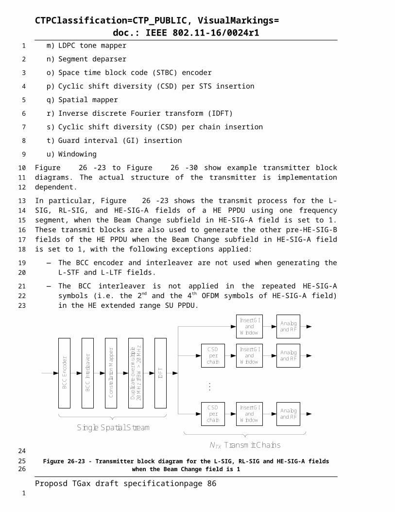
CTPClassification=CTP_PUBLIC, VisualMarkings=doc.: IEEE 802.11-16/0024r1
(26-15)
where
η is an PPDU format dependent scaling factor, as defined in Equation (26-13).
N20MHz is defined in 21.3.7.3 (Channel frequencies)KShift i( ) N20MHz 1– 2i– 32=
represents the cyclic shift for transmitter chain with a value given in 26.3.9.2 (Cyclic shift for Pre-HE modulated fields).
is defined by Equation (22-14), Equation (22-15), Equation (22-16) and Equation (22-17).
has the value given in Table 22-8 (Tone scaling factor and guard interval duration values for PHY ields(11ac)).
If the TXVECTOR parameter BEAM_CHANGE is 0, the time domain representation of the L-LTF field of contiguous 20 MHz, 40 MHz, 80 MHz and 160 MHz transmission shall be as specified in Equation (26-16). The equation applies to all contiguous signals up to 160 MHz and non contiguous 80+80 MHz.
(26-16)
where
is given in 26.3.9.2 (Cyclic shift for Pre-HE modulated fields).
is defined in Error: Reference source not found
is defined in Equation (26-57)26.3.9.5 L-SIGThe L-SIG field is used to communicate rate and length information. The structure of the L-SIG field is defined in Figure 18-5 (SIGNAL field bit assignment).
In a HE PPDU, the RATE field shall be set to the value representing 6 Mb/s in the 20 MHz channel spacing column of Table 18-6 (Contents of the SIGNAL field). In a non-HT duplicate PPDU, the RATE field is defined in 18.3.4.2 (RATE field) using the L_DATARATE parameter in the TXVECTOR.
The LENGTH field shall be set to the value given by Equation (26-17).
(26-17)
where
TXTIME (in µs) is defined in 26.4.3 (TXTIME and PSDU_LENGTH calculation).
Proposd TGax draft specification page 86
1
2
3
4
56
7
89
101112
13
14
15
1617
1819
202122
23
24
25
1

CTPClassification=CTP_PUBLIC, VisualMarkings=doc.: IEEE 802.11-16/0024r1
m is 1 for an HE MU PPDU and HE extended range SU PPDU, and 2 otherwise.
The LSB of the binary expression of the Length value shall be mapped to B5. In a non-HT duplicate PPDU, the LENGTH field is defined in 18.3.4.3 (LENGTH field) using the L_LENGTH parameter in the TXVECTOR.
The Reserved (R) field shall be set to 0.
The Parity (P) field has the even parity of bits 0-16.
The SIGNAL TAIL field shall be set to 0.
The L-SIG field shall be encoded, interleaved, and mapped following the steps described in 18.3.5.6 (Convolutional encoder), 18.3.5.7 (Data interleaving), and 18.3.5.8 (Subcarrier modulation mapping). The stream of 48 complex numbers generated by these steps is denoted by . Pilots shall be inserted as described in 18.3.5.9 (Pilot subcarriers). Extra 4 BPSK modulated tones are added, two at each edge of the subcarriers used by data and pilot tones. The 4 extra tones [-28, -27, 27, 28] of L-SIG in 20 MHz HE PPDU is [-1, -1, -1, 1].
If the TXVECTOR parameter BEAM_CHANGE is 1, the time domain waveform of the L-SIG field shall be as given by Equation (26-18).
(26-18)
whereN20MHz is defined in 21.3.7.3 (Channel frequencies)KShift i( ) N20MHz 1– 2i– 32=
M20r k
k 26 26 k 22– –+k 25 20 k 8– –+k 24 6 k 1– –+k 23 1 k 6 +k 22 8 k 20 +k 21 22 k 26 +
=
Pk is defined in 18.3.5.10 (OFDM modulation)p0 is the first pilot value in the sequence defined in 18.3.5.10 (OFDM modulation)
NL-SIGTone
has the value given in Error: Reference source not foundk BW is defined in Equation (26-8), Equation (26-9), Equation (26-10) and Equation (26-11).
TCSiTX
represents the cyclic shift for transmitter chain iTX with a value given in 26.3.9.2 (Cyclic shift for Pre-HE modulated fields)
Proposd TGax draft specification page 87
1
234
5
6
7
89
10111213
1415
16
17
18
19
20
21
22
23
24
2526
1
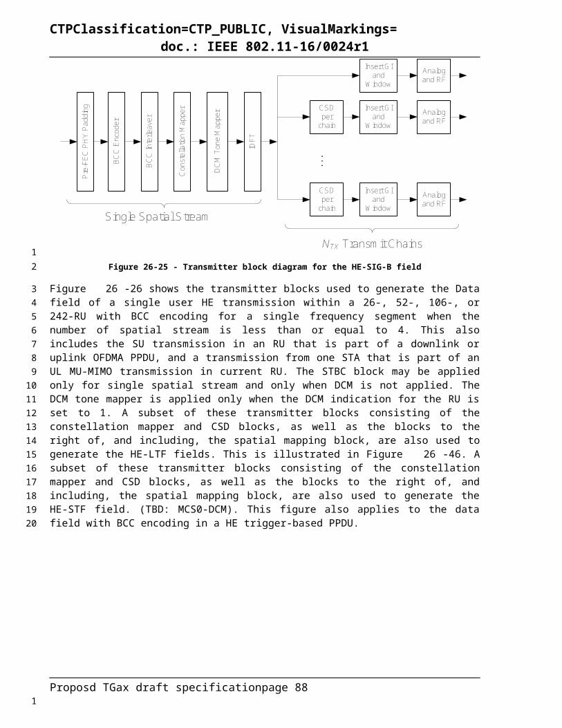
CTPClassification=CTP_PUBLIC, VisualMarkings=doc.: IEEE 802.11-16/0024r1
NOTE— is a “reverse” function of the function M(k) defined in 18.3.5.10 (OFDM modulation).
If the TXVECTOR parameter BEAM_CHANGE is 0, the time domain waveform of the L-SIG field shall be as given by Equation (26-19).
(26-19)
where
is given in 26.3.9.2 (Cyclic shift for Pre-HE modulated fields)
is defined in Error: Reference source not found
is defined in Error: Reference source not found
26.3.9.6 RL-SIGThe RL-SIG field is used to identify a HE PPDU.
The time domain waveform of the RL-SIG field is generated by repeating the time domain waveform of the L-SIG field, as defined in (26-20).
(26-20)
26.3.9.7 HE-SIG-A26.3.9.7.1 GeneralThe HE-SIG-A field carries information required to interpret HE PPDUs. The structure of the HE-SIG-A field for the first part (HE-SIG-A1) and for the second part (HE-SIG-A2) is TBD.
26.3.9.7.2 ContentThe HE-SIG-A field for an HE SU PPDU or an HE extended range SU PPDU contains the fields listed in Table 26-18.
Table 26-18 - Fields in the HE-SIG-A for an HE SU PPDU and HE extended range SU PPDU
Two Parts of HE-SIG-A
Bit Field Number of bits
Description
TBD
TBD DL/UL 1 Indicates whether the PPDU is sent UL or DL. This field indicates DL for TDLS.
NOTE—The TDLS peer can identify the TDLS frame by To DS and From DS fields in the MAC header of the MPDU.
TBD Format 1 Differentiate between an HE SU PPDU and an HE trigger-based PPDU or between an HE extended range SU PPDU and an HE trigger-based PPDU
TBD BSS Color 6 The BSS Color field is an identifier of the BSSTBD Spatial Reuse TBD TBDTBD TXOP Duration TBD Indicates the remaining time in the current TXOP.
Details TBD.
Proposd TGax draft specification page 88
1
23
4
5
6
78
9
10
1112
13
14
1516
17
1819
20
1
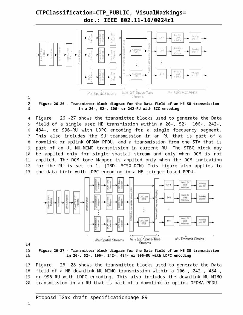
CTPClassification=CTP_PUBLIC, VisualMarkings=doc.: IEEE 802.11-16/0024r1
TBD Bandwidth 2 Set to 0 for 20 MHz, 1 for 40 MHz, 2 for 80 MHz, 3 for 160 MHz and 80+80 MHz
TBD MCS 4 HE-MCS indexTBD CP+LTF Size 3 To indicate the CP length and HE-LTF size, the
current combinations are 1x HE-LTF + 0.8 µs, 2x HE-LTF + 0.8 µs, 2x HE-LTF + 1.6 µs and 4x HE-LTF + 3.2 µs. Other combinations are TBD.
TBD Coding 2 Indication of BCC/LDPC and presence of the extra OFDM symbol for LDPC. Detailed indication is TBD.
TBD Nsts 3 Indicates the number of spatial streams: Set to 0 for 1 space time streamSet to 1 for 2 space time streamsSet to 2 for 3 space time streamsSet to 3 for 4 space time streamsSet to 4 for 5 space time streamsSet to 5 for 6 space time streamsSet to 6 for 7 space time streamsSet to 7 for 8 space time streams
TBD STBC 1 Set to 1 if space time block coding is used and set to 0 otherwise.
TBD TxBF 1 Set to 1 if a Beamforming steering matrix is applied to the waveform in an SU transmission, set to 0 otherwise.
TBD DCM 1 Set to 1 indicates that the payload of the SU PPDU is modulated with dual sub-carrier modulation for the MCS. Set to 0 indicates that the payload of the PPDU is not modulated with dual sub-carrier modulation for the MCS.
TBD Packet Extension 3 The first two bits indicate the “a-factor” and the third bit indicates the PE-Disambiguity.
TBD Beam Change 1 Set to 1 indicates that the pre-HE-STF portion of the SU PPDU is spatially mapped differently from HE-LTF1.Set to 0 indicates that the pre-HE-STF portion of the SU PPDU is spatially mapped the same way as HE-LTF1 on each tone.
TBD CRC 4 CRC of bits 0–41 in HT-SIG-A. See 22.3.9.7.1 (CRC calculation for HE-SIG-A). The first bit to be transmitted is bit C3 as explained in 20.3.9.7.1 (CRC calculation for HE-SIG).
TBD Tail 6 Used to terminate the trellis of the convolutional decoder.Set to 0.
NOTE—The HE-SIG-A field contents for the HE extended range SU PPDU may be subject to change.
The HE-SIG-A field of an HE MU PPDU contains the fields listed in Table 26-19.Table 26-19 - Fields in the HE-SIG-A for a HE MU PPDU
Two Parts of HE-SIG-A
Bit Field Number of Bits
Description
TBD DL/UL 1 Indicates whether the HE MU PPDU is UL or DL. This field indicates DL for TDLS.
NOTE—The TDLS peer can identify the TDLS frame by To DS and From DS fields in the MAC header of the 11ax MPDU.
TBD BSS Color 6 The BSS Color field is an identifier of the BSSTBD Spatial Reuse TBD TBDTBD TXOP Duration TBD Indicates the remaining time in the current TXOP.
Details TBD.
Proposd TGax draft specification page 89
1
2
3
4
1

CTPClassification=CTP_PUBLIC, VisualMarkings=doc.: IEEE 802.11-16/0024r1
TBD
TBD Bandwidth ≥ 2 Set to 0 for 20 MHz, 1 for 40 MHz, 2 for 80 MHz, 3 for 160 MHz and 80+80 MHz
TBD SIGB MCS 3 Indication the MCS of HE-SIG-B. Set to 0 for MCS0Set to 1 for MCS1Set to 2 for MCS2Set to 3 for MCS3Set to 4 for MCS4Set to 5 for MCS5
TBD SIGB DCM 1 Set to 1 indicates that the HE-SIG-B is modulated with dual sub-carrier modulation for the MCS. Set to 0 indicates that the HE-SIB-B is not modulated with dual sub-carrier modulation for the MCS.
TBD SIGB Number Of Symbols
4 Indciates the number of HE-SIG-B symbols.
TBD SIGB Compression
1 Set to 1 for full BW MU-MIMO.Set to 0 otherwise.
TBD Number of HE-LTF Symbols
3 Indicates the number of HE-LTF symbols.
TBD CP+LTF Size 3 To indicate the CP length and HE-LTF size, the current combinations are 1x HE-LTF + 0.8 µs, 2x HE-LTF + 0.8 µs, 2x HE-LTF + 1.6 µs and 4x HE-LTF + 3.2 µS. Other combinations are TBD.
TBD LPDC Extra Symbol
1 Indication of the presence of the extra OFDM symbol for LDPC.
TBD Packet Extension 3 The first two bits indicate the “a-factor” and the third bit indicates the PE-Disambiguity.
TBD CRC 4 CRC of bits 0–41 in HT-SIG-A. See 22.3.9.7.1 (CRC calculation for HE-SIG-A). The first bit to be transmitted is bit C3 as explained in 20.3.9.7.1 (CRC calculation for HE-SIG).
TBD Tail 6 Used to terminate the trellis of the convolutional decoder.Set to 0.
The HE-SIG-A field for an HE trigger-based PPDU contains the fields listed in Table 26-20.Table 26-20 - HE Fields in the HE-SIG-A for a HE trigger-based PPDU
Two Parts of HE-SIG-A
Bit Field Number of Bits
Description
TBD
TBD Format 1 Set to 0 for an HE SU PPDU Set to 1 for an HE trigger-based PPDU
TBD BSS Color 6 The BSS Color field is an identifier of the BSSTBD Spatial Reuse TBD TBDTBD TXOP Duration TBD Indicates the remaining time in the current TXOP.
Details TBD.TBD Bandwidth TBD TBDTBD Reserved TBD TBDTBD CRC 4 CRC of bits 0–41 in HT-SIG-A. See 22.3.9.7.1 (CRC
calculation for HE-SIG-A). The first bit to be transmitted is bit C3 as explained in 20.3.9.7.1 (CRC calculation for HE-SIG).
TBD Tail 6 Used to terminate the trellis of the convolutional decoder.Set to 0.
26.3.9.7.3 CRC computationThe CRC computation defined in this subclause applies to HE-SIG-A, the Common field of HE-SIG-B and the User Specific field of HE-SIG-B.
Proposd TGax draft specification page 90
1
2
3
45
1

CTPClassification=CTP_PUBLIC, VisualMarkings=doc.: IEEE 802.11-16/0024r1
The CRC protects bits 0–L of the HE-SIG (L=41 for HE-SIG-A, or L=x for each HE-SIG-B common block fields, or L=x for HE-SIG-B user specific fields). The value of the CRC field shall be the 1s complement of
crc ( D )=(M (D )+ I ( D ) )D 8mod G ( D )
where
M (D )=∑i=0
L
mL−i Di
where
mi is bit i in the field
I ( D )= ∑i=L−7
L
Di
G(D) and crc(D) are defined in Equation (20-18).
The CRC field is transmitted from c5 to c7 with c7 first.Figure 20-8 (HT-SIG CRC calculation) shows the operation of the CRC, where the serial input are from mL to m0, and the output is stopped at c4.26.3.9.7.4 Encoding and modulationFor an HE SU PPDU, HE MU PPDU and HE trigger-based PPDU, the HE-SIG-A field is composed of two parts, HE-SIG-A1 and HE-SIG-A2, each containing 26 data bits. HE-SIG-A1 is transmitted before HE-SIG-A2. The HE-SIG-A symbols shall be BCC encoded at rate, R = 1/2, interleaved, mapped to a BPSK constellation, and have pilots inserted following the steps described in 18.3.5.6 (Convolutional encoder), 18.3.5.7 (Data interleaving), 18.3.5.8 (Subcarrier modulation mapping), and 18.3.5.9 (Pilot subcarriers), respectively. The constellation mappings of HE-SIG-A in HE SU PPDU, HE MU PPDU and HE trigger-based PPDU are shown in Figure 26-39. The first and second half of the stream of 104 complex numbers generated by these steps (before pilot insertion) is divided into two groups of 52 complex numbers, where respectively, the first 52 complex numbers form the first symbol of HE-SIG-A and the second 52 complex numbers form the second symbol of HE-SIG-A. If the TXVECTOR parameter BEAM_CHANGE is 1, the time domain waveform for the HE-SIG-A field of an HE SU PPDU, HE MU PPDU and HE trigger-based PPDU shall be as specified in Equation (26-21).
(26-21)
where
N20MHz is defined in 21.3.7.3 (Channel frequencies)KShift i( ) N20MHz 1– 2i– 32=
Proposd TGax draft specification page 91
123
4
5
6
7
8
9
10
11
121314
151617181920212223242526
27
28
2930
3132
1

CTPClassification=CTP_PUBLIC, VisualMarkings=doc.: IEEE 802.11-16/0024r1
Pk and pn are defined in 18.3.5.10 (OFDM modulation).
N HE−SIG−ATone has the value given in Error: Reference source not found
k BW is defined in Equation (26-8), Equation (26-9), Equation (26-10) and Equation (26-11).
TCSiTX
represents the cyclic shift for transmitter chain iTX with a value given in 26.3.9.2 (Cyclic shift for Pre-HE modulated fields)
If the TXVECTOR parameter BEAM_CHANGE is 0, the time domain waveform of the HE-SIG-A field shall be as given by Equation (26-22).
(26-22)
where
is given in 26.3.9.2 (Cyclic shift for Pre-HE modulated fields)
is defined in Error: Reference source not found
is defined in Equation (26-57)
For an HE extended range SU PPDU, the HE-SIG-A field is composed of four parts, i.e. HE-SIG-A1, HE-SIG-A2, HE-SIG-A3 and HE-SIG-A4, each part containing 26 data bits. These four parts are transmitted sequentially from HE-SIG-A1 to HE-SIG-A4. HE-SIG-A1 and HE-SIG-A2 have the same data bits. HE-SIG-A3 and HE-SIG-A4 have same data bits. The data bits of HE-SIG-A1 and HE-SIG-A3 shall be BCC encoded at rate, R = 1/2, interleaved, mapped to a BPSK constellation, and have pilots inserted. HE-SIG-A2 shall be BCC encoded at rate, R=1/2, mapped to a QBPSK constellation and have pilots inserted. The constellation mappings of the HE-SIG-A field in an HE extended range SU PPDU is shown in Figure 26-39. QBPSK constellation on HE-SIG-A2 is used to differentiate between an HE extended range SU PPDU and an HE MU PPDU. HE-SIG-A4 shall be BCC encoded at rate, R=1/2, mapped to a BPSK constellation and have pilots inserted. BCC encoding, Data interleaving, constellation mapping and pilot insertion follow the steps described in 18.3.5.6 (Convolutional encoder), 18.3.5.7 (Data interleaving), 18.3.5.8 (Subcarrier modulation mapping), and 18.3.5.9 (Pilot subcarriers), respectively.
If the TXVECTOR parameter BEAM_CHANGE is 1, the time domain waveform for the HE-SIG-A field in an HE extended range SU PPDU, shall be as specified in Equation (26-23).
Proposd TGax draft specification page 92
1
2
3
4
56
78
9
10
11
12
131415161718192021222324
2526
1
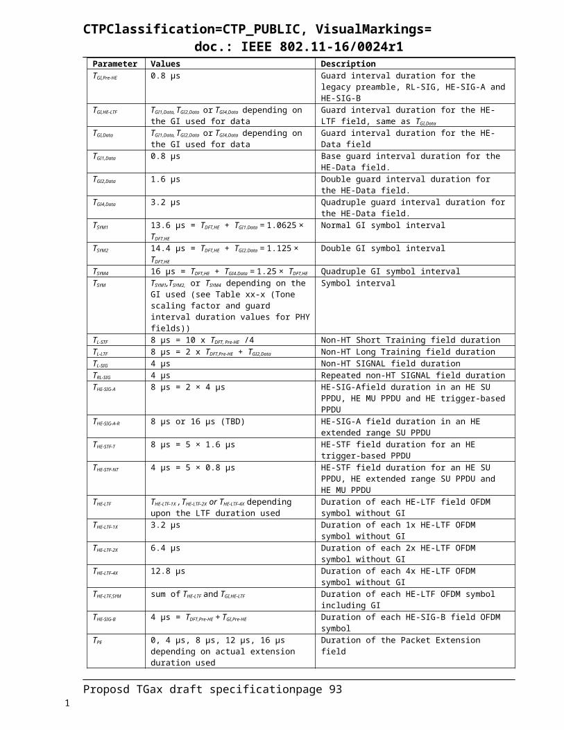
CTPClassification=CTP_PUBLIC, VisualMarkings=doc.: IEEE 802.11-16/0024r1
(26-23)
where
R is a phase rotation vector defined as [1 , j , 1,1 ].If the TXVECTOR parameter BEAM_CHANGE is 0, the time domain waveform for the HE-SIG-A field in an HE extended range SU PPDU, shall be as specified in Equation (26-24).
(26-24)
HE-SIG-A1 symbol with
BPSK
HE-SIG-A2symbol with
BPSK
HE_SU PPDU, HE_TRIG PPDU
and HE_MU PPDU
I
Q
+1 -1 I
Q
+1 -1
HE-SIG-A1 symbol with
BPSK
HE-SIG-A2symbol with
QBPSK
HE_EXT_SU PPDU
I
Q
+1 -1 I
Q +1
-1
HE-SIG-A3symbol with
BPSK
HE-SIG-A4symbol with
BPSK
I
Q
+1 -1 I
Q
+1 -1
Figure 26-39 - Data tone constellation of HE-SIG-A symbols
26.3.9.8 HE-SIG-B26.3.9.8.1 Encoding and modulationThe HE-SIG-B field is separately encoded on each 20 MHz band. The encoding structure in one such 20 MHz band is shown in Figure 26-40. It consists of a Common Block field followed by a User Specific field.
Proposd TGax draft specification page 93
1
2
34
56
78
9
10
111213
14
1

CTPClassification=CTP_PUBLIC, VisualMarkings=doc.: IEEE 802.11-16/0024r1
Figure 26-40 – HE-SIG-B field encoding structure in each 20 MHz
The Common Block field contains information regarding the resource unit allocation such as the RU arrangement in frequency domain, the RUs allocated for MU-MIMO and the number of users in MU-MIMO allocations. The Common Block field is described in detail in 25.3.9.2.5.2
The User Specific field consists of multiple User Block fields. Each User Block field contains information for two STAs to decode their payloads. The last User Block field may contain information for only one STA, if the number of user fields indicated by the RU allocation signaling in the common block is odd. See 25.3.9.2.5.3 for a description of the contents of the User Block field.
26.3.9.8.1.1 Frequency domain mappingFor 20 MHz and 40 MHz PPDUs, the Common Block field and the User field for a STA are transmitted in the same 20 MHz band as the STA’s data as shown in Figure 26-41 and Figure 26-42.
Figure 26-41 HE-SIG-B content channel for a 20 MHz PPDU
Figure 26-42 - HE-SIG-B content channels for a 40 MHz PPDU
For an 80 MHz PPDU, the default frequency mapping of the Common Block field and User Specific fields is shown in Figure 26-43. The HE-SIG-B field content in the 1st and 3rd 20 MHz bands from the top are identical. The information carried in either of these bands is called HE-SIG-B content channel 1. HE-SIG-B content channel 1 carries signaling information for all STAs whose payloads occupy some tones in A242 or C242. Similarly, the HE-SIG-B contents on the 2nd and 4th 20 MHz bands are identical. The information carried in either of these bands is called HE-SIG-B content channel 2. HE-SIG-B content channel 2 carries signaling information for all STAs whose payloads occupy some tones in B242 or D242.
Figure 26-43 - Default mapping of the two HE-SIG-B channels and their duplication in an 80 MHz PPDU
For a 160 MHz PPDU, the default frequency mapping of the Common Block field and User Specific fields is shown in Figure 26-44. The HE-SIG-B content in the 1st, 3rd, 5th and 7th 20 MHz bands from
Proposd TGax draft specification page 94
12
345
6789
10
1112
1314
1516
1718192021222324
2526
2728
1

CTPClassification=CTP_PUBLIC, VisualMarkings=doc.: IEEE 802.11-16/0024r1
top are all identical. The information carried in any of these bands is called HE-SIG-B content channel 1. HE-SIG-B content channel 1 carries signaling information for all STAs whose payloads occupy some tones in A1-242 or C1-242 or A2-242 or C2-242. Similarly, the HE-SIG-B contents in the 2nd, 4th, 6th and 8th 20 MHz bands from top are identical. The information carried in any of these bands is called HE-SIG-B content channel 2. HE-SIG-B content channel 2 carries signaling information for all STAs whose payloads occupy some tones in B1-242 or D1-242 or B2-242 or D2-242.
Figure 26-44 - Default mapping of the two HE-SIG-B channels and their duplication in a 160 MHz PPDU
For MU-MIMO allocation of RU size > 20 MHz, the User Block subfields are dynamically split between the two HE-SIG-B content channels (1/2) and the split is decided by the AP (on a per case basis). See 25.3.9.2.5.2 and 25.3.9.2.5.3 for more details.
26.3.9.8.1.2 Time domain encodingIn each 20 MHz band, the bits in the Common Block field shall have CRC and tail bits added and then be BCC encoded at rate R = ½. Padding bits are not added after the common block.
In the User Specific field, in any 20 MHz band, the bits corresponding to two STAs (i.e. two User fields) are encoded together. Specifically, the STAs scheduled in the HE-MU-PPDU are split into groups of two. Each group of two User fields shall have CRC and tail bits added and then BCC encoded at rate R = ½ using the encoder described in 18.3.5.6. If the number of users is even, padding bits are added to round up the number of symbols to the nearest integer. If the number of users is odd, the User Block field corresponding to the last user, who is not grouped, is encoded after adding tail and CRC bits and only then are any padding bits added. The padding bits added ensure that both content channels have the same number of symbols. The specific method of generating padding bits is TBD. When the code rate is not equal to ½, the convolutional encoder output bits for each field (including padding bits) are concatenated, then the concatenated bit streams are punctured continuously as described in 18.3.5.6 (Convolutional encoder).
The number of data tones in each symbol is NSD = 52. The coded bits are interleaved as in 22.3.10.8, with the parameter Ncol = 13 (as in Table 22-17, for 20 MHz). The interleaved bits are mapped to constellation points from the MCS specified in HE-SIG-A and have pilots inserted following the steps described in 18.3.5.7 (Data Interleaving), 18.3.5.8 (Subcarrier modulation mapping) and 18.3.5.9 (Pilot subcarriers) respectively.
The cyclic prefix used for HE-SIG-B shall be 0.8 μs. The number of symbols in HE-SIG-B, denoted by NSYM,HE-SIG-B, shall be signaled in HE-SIG-A in the default mode (see Section 25.3.9.2.4). For the cth content channel (c = 1 or 2), denote the sample on the kth subcarrier of the nth symbol by dk,n,c
. The time domain waveform for the HE-SIG-B follows Equation (26-25).
Proposd TGax draft specification page 95
123456
78
91011
12
1314
1516171819202122232425
2627282930
31323334
1

CTPClassification=CTP_PUBLIC, VisualMarkings=doc.: IEEE 802.11-16/0024r1
(26-25)
26.3.9.8.2 HE-SIG-B common contentThe Common block field in the HE-SIG-B carries RU allocation subfields. Depending on the PPDU bandwidth, the Common block field can contain multiple RU allocation subfields.
An RU allocation subfield in the Common block field of HE-SIG-B consists of 8 bits that indicates the following for a 20 MHz PPDU BW:
— The RU arrangement in the frequency domain: indexes the size of the RUs and their placement in the frequency domain.
— Number of user fields in each RU in the HE-SIG-B content channel: the number of users multiplexed in the RUs indicated by the arrangement; for RUs of size greater than or equal to 106 tones that support MU-MIMO, it indicates the number of users multiplexed using MU-MIMO.
The mapping of the 8-bit RU allocation subfield to the RU arrangement and the number of user fields per RU is defined in the Table 26-21. In the table, the number of entries column refers to the number of 8-bit indices that refer to the same RU arrangement in the frequency domain but differ in the number of users fields per RU. The RU arrangement and the number of user fields per RU together indicate the number of user-fields in the User specific field of HE-SIG-B. Signaling for the center 26 unit in 80 MHz is [TBD].
Table 26-21 - RU allocation signalling: Arrangement and number of MU-MIMO allocations
8 bits indices #1 #2 #3 #4 #5 #6 #7 #8 #9 Number of entries
000 0 0000 26 26 26 26 26 26 26 26 26 1000 0 0001 26 26 26 26 26 26 26 52 1000 0 0010 26 26 26 26 26 52 26 26 1000 0 0011 26 26 26 26 26 52 52 1000 0 0100 26 26 52 26 26 26 26 26 1000 0 0101 26 26 52 26 26 26 52 1000 0 0110 26 26 52 26 52 26 26 1
Proposd TGax draft specification page 96
12
34
56
78
91011
1213141516
17
1

CTPClassification=CTP_PUBLIC, VisualMarkings=doc.: IEEE 802.11-16/0024r1
000 0 0111 26 26 52 26 52 52 1000 0 1000 52 26 26 26 26 26 26 26 1000 0 1001 52 26 26 26 26 26 52 1000 0 1010 52 26 26 26 52 26 26 1000 0 1011 52 26 26 26 52 52 1000 0 1100 52 52 26 26 26 26 26 1000 0 1101 52 52 26 26 26 52 1000 0 1110 52 52 26 52 26 26 1000 0 1111 52 52 26 52 52 1000 1 xxxx Definition TBD 1600100 yyy 26 26 26 26 26 106 800101 yyy 26 26 52 26 106 800110 yyy 52 26 26 26 106 800111 yyy 52 52 26 106 801000 yyy 106 26 26 26 26 26 801001 yyy 106 26 26 26 52 801010 yyy 106 26 52 26 26 801011 yyy 106 26 52 52 8011 xxxxx Definition TBD 3210 yyy yyy 106 26 106 6411 0 00yyy 242 811 0 01yyy 484 811 0 10yyy 996 811 0 11yyy 2*996 811 1 xxxxx Definition TBD 32
NOTE: yyy’ = 000~111 indicates number of STAs multiplexed in an RU. Binary vector yyy is indexed as [ y [3 ] y [2 ] y [1 ]] indicates
22× y [3 ]+21 × y [2 ]+ y [1] + 1 STAs multiplexed in the RU.
The definition for entries with ‘x’ bits is TBD.
The number of RU allocation subfields in the HE-SIG-B common block field depends on the total PPDU bandwidth
— In the default mode, for 20 MHz and 40 MHz PPDU, each HE-SIG-B content channel contains one RU allocation subfield followed by multiple user fields. The position of the user-field in the user-specific field together with the 8-bit RU allocation subfield indicates the RU assignment to the user.
— In the default mode for the 80 MHz PPDU, each HE-SIG-B content channel contains two RU allocation subfields for a total of 16 bits of RU allocation signaling, one each for the RUs in the two 20 MHz segments of the HE-SIG-B content channel. The user fields corresponding to the first RU allocation signaling field are followed by the user fields indicated by the second RU allocation signaling field in the user specific field.
In the default mode for the 160 MHz PPDU, each HE-SIG-B content channel contains four RU allocation signaling fields for a total of 32 bits of RU allocation signaling, one each for the RUs in the four 20 MHz segments of the HE-SIG-B content channel. The user fields for each of the 20 MHz segments in the content channel are arranged by the order in which their RU allocation signaling fields appear in the common field.
26.3.9.8.3 HE-SIG-B per-user contentThe user-specific field consists of multiple user fields. The user fields follow the common block field of HE-SIG-B. The RU allocation subfield in the Common block field and the position of the user field in the HE-SIG-B user specific field together identify the RU used to transmit a STA’s data. An example for the mapping of the 8-bit RU allocation subfield and the position of the user field to an STA’s data is illustrated in Figure 26-45. The RU arrangement signaling indicates an arrangement of 106 tone RU
Proposd TGax draft specification page 97
12
3456
789
1011
1213141516
17
1819202122
1

CTPClassification=CTP_PUBLIC, VisualMarkings=doc.: IEEE 802.11-16/0024r1
followed by five 26-tone RUs and that the 106-tone RU contains three user-fields, i.e., the 106-tone RU supports multiplexing of three users using MU-MIMO. The eight user fields in the HE-SIG-B user-specific field thus map to the 6 RUs, with the first three user fields indicating MU-MIMO allocations in the first 106-tone RU followed by user fields corresponding to the each of the five 26-tone RUs.
RU Allocation Sub-field01000yyy = 0100011
106 26 26 26 26 26
Number of user-fields per RU
RU Arrangement in Frequency domain
3 1 1 1 1 1
User Field #1
User Field #2
User Field #3
User Field #4
User Field #8
User Field #5
User Field #6
User Field #7
HE-SIG-B Common Block Field HE-SIG-B User Specific Fields
MU-MIMO Allocations
Figure 26-45 - Illustration for the mapping of the 8-bit RU allocation subfield and the position of the user-field to the STA's assignment
The contents of the user field differ based on whether the field addresses a single-STA in an RU or a STA in a MU-MIMO allocation in an RU. Irrespective of whether the allocation is for a STA in a SU or an MU-MIMO allocation, the size of the userfield is the same.
The HE-SIG-B user field for a SU allocation contain the subfields shown in Table 26-22.Table 26-22 - Fields of the HE-SIG-B user field for a SU allocation
Bit Subfield Number of bits
Description
TBD
STA-ID 11 The STA identifier that addresses a STA – reference to MAC section(?). For RUs that carry a broadcast allocation:For single BSS AP, the STAID for Broadcast will be 0; For Multiple BSS AP, the STAID for Broadcast to a specific BSS will follow the group addressed AID assignment in the TIM according to the existing Multi-BSSID TIM operation; For Multiple BSS AP, the STAID for Broadcast to all BSS of the AP will have a special STAID value reserved.
TBD
NSTS 3 Number of spatial streams
TBD
Tx Beamforming
1 Use of transmit beamforming
TBD
MCS 4 Modulation and Coding Scheme
TBD
DCM 1 Indication for use of dual carrier modulation
TBD
Coding 1 Indication for use of LDPC
The HE-SIG-B user field for an STA in MU-MIMO allocation contain the subfields shown in Table 26-23.
Table 26-23 - Fields of the HE-SIG-B user field for a MU-MIMO allocation
Bit Subfield Number of bits
Description
TBD
STA-ID 11 The STA identifier that addresses an STA – reference to MAC section(?)
TBD
Spatial Configuration
4 Indication for the number of spatial streams for a STA in a MU-MIMO allocation. See Table 26-24.
TBD
MCS 4 Modulation and Coding Scheme
Proposd TGax draft specification page 98
1234
567
89
10
11
12
13
1415
16
1

CTPClassification=CTP_PUBLIC, VisualMarkings=doc.: IEEE 802.11-16/0024r1
TBD
DCM 1 Use of dual carrier modulation
TBD
Coding 1 Use of LDPC
A user field for an MU-MIMO allocation includes a Spatial Configuration subfield consisting of 4 bits that indicates the number of spatial streams for each STA and the total number of spatial streams in the MU-MIMO allocation. The subfield shown in Table 26-24 is constructed by using the entries corresponding to the value of number of users (Nuser) multiplexed using MU-MIMO in an RU. When MU-MIMO is used in an RU of size ≤ 20 MHz, the number of users (Nuser) in an MU-MIMO allocation is equal to the number of user-fields per RU signalled for the RU in the RU allocation subfield of an HE-SIG-B Common block field. When MU-MIMO is used in RUs of size 20 MHz or greater, the number of users (Nuser) in an MU-MIMO allocation is computed as the sum of the number of user-fields per RU indicated for the RU by the 8-bit RU allocation subfield in each HE-SIG-B content channel. For a given value of Nuser, the four bits of the spatial configuration subfield are used as follows: A STA with a STA-ID that matches the 11-bit ID signalled in the user field for an MU-MIMO allocation derives the number of spatial streams allocated to it using the row corresponding to the signalled 4-bit spatial configuration subfield and the column corresponding to the position of the user-field in the user-specific field. The starting stream index for the STA is computed by summing the Nsts in the columns prior to the column indicated by the STA’s user-field position. In the case of load balancing for RUs of size > 20 MHz where user fields corresponding to the same MU-MIMO allocations are split into two HE-SIG-B content channels, the user-field positions are logically continuous with the user-field in the second HE-SIG-B content channel updating its position (and therefore, column index) from that of the last user-field in the first HE-SIG-B content channel.
Table 26-24 - Spatial Configuration subfield encoding
Nuser B0…B3 Nsts[1]
Nsts[2]
Nsts[3]
Nsts[4]
Nsts[5]
Nsts[6]
Nsts[7]
Nsts[8]
TotalNsts
Number of Entries
2 0000~0011 1~4 1 2~5 10
0100~0110 2~4 2 4~6
0111~1000 3~4 3 6~7
1001 4 4 8
3 0000~0011 1~4 1 1 3~6 13
0100~0110 2~4 2 1 5~7
0111~1000 3~4 3 1 7~8
1001~1011 2~4 2 2 6~8
1100 3 3 2 8
4 0000~0011 1~4 1 1 1 4~7 11
0100~0110 2~4 2 1 1 6~8
0111 3 3 1 1 8
1000~1001 2~3 2 2 1 7~8
1010 2 2 2 2 8
5 0000~0011 1~4 1 1 1 1 5~8 6
0100~0101 2~3 2 1 1 1 7~8
6 0000~0010 1~3 1 1 1 1 1 6~8 4
0011 2 2 1 1 1 1 8
Proposd TGax draft specification page 99
123456789
10111213141516171819
20
1

CTPClassification=CTP_PUBLIC, VisualMarkings=doc.: IEEE 802.11-16/0024r1
7 0000~0001 1~2 1 1 1 1 1 1 7~8 2
8 0000 1 1 1 1 1 1 1 1 8 1
26.3.9.9 HE-STFThe main purpose of the HE-STF field is to improve automatic gain control estimation in a MIMO transmission. The duration of the HE-STF field for HE PPDUs except HE trigger-based PPDUs is THE-STF-
NT (peridiocity of 0.8 µs with 5 periods) and the duration of the HE-STF field for an HE trigger-based PPDU is THE-STF-T (peridiocity of 1.6 µs with 5 periods). The tone indices for HE-STF field for HE PPDUs except HE trigger-based PPDUs is defined in Equation (26-26).
(26-26)
The tone indices for HE-STF fields for an HE trigger-based PPDU are defined in Equation (26-27).
(26-27)
For the HE-STF field, the M sequence is defined by Equation (26-28).
M = {-1, -1, -1, 1, 1, 1, -1, 1, 1, 1, -1, 1, 1, -1, 1}(26-28)
The HE-STF field is constructed from the M sequence(s) by multiplying integer coefficient(s) to each 20 MHz subchannel and inserting appropriate coefficients into tone indices which are null after mapping M sequences.
For a 20 MHz transmission, the frequency domain sequence for HE PPDUs except HE trigger-based PPDUs is given by Equation (26-29).
(26-29)
where HESa:b:c means coefficients of the HE-STF on every b tone indices from a to c tone indices and coefficients on other tone indices are set to zero.
For a 40 MHz transmission, the frequency domain sequence for HE PPDUs except HE trigger-based PPDUs is given by Equation (26-30).
(26-30)
For an 80 MHz transmission, the frequency domain sequence for HE PPDUs except HE trigger-based PPDUs is given by Equation (26-31).
(26-31)
For a 20 MHz transmission, the frequency domain sequence for HE trigger-based PPDUs is given by Equation (26-32).
(26-32)
Proposd TGax draft specification page 100
1
2
34567
8
9
101112
1314
1516
1718
1920
2122
1

CTPClassification=CTP_PUBLIC, VisualMarkings=doc.: IEEE 802.11-16/0024r1
For a 40 MHz transmission, the frequency domain sequence for HE trigger-based PPDUs is given by Equation (26-33).
(26-33)
For an 80 MHz transmission, the frequency domain sequence for HE trigger-based PPDUs is given by Equation (26-34).
(26-34)
For an OFDMA transmission, the coefficients in Equation (25-3) to (25-8) are set to zero if those values are corresponding to tone indices on which no RUs defined in 25.3.7.1 are assigned.
The time domain representation of the signal for HE PPDUs except HE trigger-based PPDUs on frequency segment iSeg of transmit chain iTX shall be as specified in Equation (26-35).
(26-35)
where
is the power boost factor for the r-th RU, where ηEXT is an PPDU format dependent scaling factor, with the following value
ηEXT={√2 , HE extended range SU PPDU1 , otherwise
is the per-RU power normalization factor and defined by
is the cardinality of the set of subcarriers Kr
is the set of subcarriers that have non-zero values within Kr in the HE-STF field
is given in 26.3.9.2 (Cyclic shift for Pre-HE modulated fields)
is defined in 25.3.10.10.x (Transmission in HE format)
is the windowing function for HE-STF field in the non-HE trigger-based PPDU.
Proposd TGax draft specification page 101
12
345
67
89
10
11
12
13
14
15
16
17
18
19
20
1
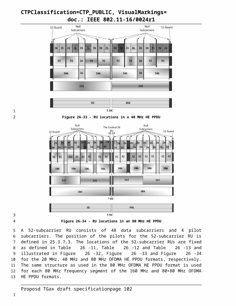
CTPClassification=CTP_PUBLIC, VisualMarkings=doc.: IEEE 802.11-16/0024r1
The time domain representation of the signal for HE trigger-based PPDUs on frequency segment iSeg of transmit chain iTX shall be as specified in Equation (26-36).
(26-36)
where
is the windowing function for HE-STF field in the HE trigger-based PPDU.26.3.9.10 HE-LTFThe HE Long Training field (HE-LTF) field provides a means for the receiver to estimate the MIMO channel between the set of constellation mapper outputs (or, if STBC is applied, the STBC encoder outputs) and the receive chains. In an HE SU PPDU, HE MU PPDU or HE extended range SU PPDU, the transmitter provides training for NSTS,r,total space-time streams (spatial mapper inputs) used for the transmission of the PSDU(s) in the r-th RU; in an HE trigger-based PPDU, the transmitter of user-u in the r-th RU provides training for NSTS,r,u space-time streams used for the transmission of the PSDU. For each tone in the r-th RU, the MIMO channel that can be estimated is an NRX NSTS,r,total matrix. A HE transmission has a preamble that contains HE-LTF symbols, where the data tones of each HE-LTF symbol are multiplied by entries belonging to a matrix PHE-LTF, to enable channel estimation at the receiver. The pilot tones of each HE-LTF symbol are multiplied by the entries of a matrix RHE-LTF defined in the following text. The multiplication of the pilot tones in the HE-LTF symbol by the RHE-LTF matrix instead of the PHE-LTF matrix allows receivers to track phase and frequency offset during MIMO channel estimation using the HE-LTF. In an HE SU PPDU and HE extended range SU PPDU, the number of HE-LTF symbols, NHE-LTF, is a function of the total number of space-time streams NSTS as shown in Error:Reference source not found. In an HE trigger-based PPDU, NHE-LTF is indicated in the Trigger frame that triggers the transmission of the PPDU. In an HE MU PPDU, NHE-LTF is indicated in the HE-SIG-A field. In an HE MU PPDU and HE trigger-based PPDU, NHE-LTF is selected to be not smaller than the maximum value of the functions for each NSTS,r,total. As a result the HE-LTF field consists of one, two, four, six or eight symbols.
A HE PPDU supports 3 HE-LTF modes, which are 1x HE-LTF, 2x HE-LTF, and 4x HE-LTF. It is optional to support 1x HE-LTF in an HE SU PPDU, HE extended range SU PPDU and HE MU PPDU. In an HE SU PPDU, HE MU PPDU or HE extended range SU PPDU, the combination of HE-LTF modes and GI duration is indicated in HE-SIG-A field. In an HE trigger-based PPDU, the combination of HE-LTF modes and GI duration is indicated in the Trigger frame that triggers the transmission of the PPDU. The mandatory combinations of HE-LTF modes and GI duration are:
— 2x HE-LTF, TGI,Data — 2x HE-LTF, TGI,Data2
— 4x HE-LTF, TGI,Data4
The optional combinations of HE-LTF mode and GI duration are:
— 1x HE-LTF, TGI,Data in a HE SU PPDU or HE extended SU PPDU— 1x HE-LTF, T GI,Data in a non-OFDMA, MU-MIMO HE MU PPDU— 1x HE-LTF, T GI,Data2 in a non-OFDMA, MU-MIMO HE trigger-based PPDU
The duration of each HE-LTF symbol is THE-LTF is defined in Equation (26-37). In an HE SU PPDU, HE MU PPDU or HE extended range SU PPDU, the HE-LTF symbol duration is indicated in HE-SIG-A
Proposd TGax draft specification page 102
12
3
45
6789
101112131415161718192021222324
252627282930
313233
34
353637
3839
1

CTPClassification=CTP_PUBLIC, VisualMarkings=doc.: IEEE 802.11-16/0024r1
field. In an HE trigger-based PPDU, the HE-LTF symbol duration is indicated in the Trigger frame that triggers the transmission of the PPDU.
(26-37)
where THE-LTF-1X, THE-LTF-2X,THE-LTF-4x are defined in Table 26-6 (Timing related constants).
In a 20 MHz transmission, the 1x HE-LTF sequence transmitted is given by Equation (26-38).
HELTF-122,122 =
{0, 0, -1, 0, 0, 0, +1, 0, 0, 0, +1, 0, 0, 0, -1, 0, 0, 0, +1, 0, 0, 0, -1, 0, 0, 0, +1, 0, 0, 0, +1, 0, 0, 0, +1, 0, 0, 0, +1, 0, 0, 0, -1, 0, 0, 0, -1, 0, 0, 0, +1, 0, 0, 0, +1, 0, 0, 0, +1, 0, 0, 0, -1, 0, 0, 0, -1, 0, 0, 0, -1, 0, 0, 0, +1, 0, 0, 0, -1, 0, 0, 0, -1, 0, 0, 0, +1, 0, 0, 0, +1, 0, 0, 0, -1, 0, 0, 0, -1, 0, 0, 0, +1, 0, 0, 0, -1, 0, 0, 0, -1, 0, 0, 0, +1, 0, 0, 0, -1, 0, 0, 0, 0, 0, 0, 0, -1, 0, 0, 0, +1, 0, 0, 0, +1, 0, 0, 0, +1, 0, 0, 0, +1, 0, 0, 0, +1, 0, 0, 0, +1, 0, 0, 0, -1, 0, 0, 0, -1, 0, 0, 0, -1, 0, 0, 0, -1, 0, 0, 0, -1, 0, 0, 0, +1, 0, 0, 0, -1, 0, 0, 0, -1, 0, 0, 0, -1, 0, 0, 0, +1, 0, 0, 0, -1, 0, 0, 0, -1, 0, 0, 0, +1, 0, 0, 0, -1, 0, 0, 0, -1, 0, 0, 0, +1, 0, 0, 0, -1, 0, 0, 0, +1, 0, 0, 0, -1, 0, 0, 0, -1, 0, 0, 0, -1, 0, 0, 0, -1, 0, 0, 0, -1, 0, 0}
(26-38)
In a 20 MHz transmission, the 2x HE-LTF sequence transmitted is given by Equation (26-39).
HELTF-122,122 = {-1, 0, -1, 0, -1, 0, +1, 0, +1, 0, -1, 0, +1, 0, -1, 0, -1, 0, -1, 0, -1, 0, +1, 0, -1, 0, +1, 0, -1, 0, -1, 0, +1, 0, +1, 0, -1, 0, +1, 0, +1, 0, +1, 0, +1, 0, +1, 0, -1, 0, +1, 0, -1, 0, +1, 0, -1, 0, -1, 0, +1, 0, +1, 0, -1, 0, +1, 0, -1, 0, -1, 0, -1, 0, -1, 0, +1, 0, -1, 0, +1, 0, +1, 0, +1, 0, -1, 0, -1, 0, +1, 0, -1, 0, -1, 0, -1, 0, -1, 0, -1, 0, +1, 0, -1, 0, -1, 0, -1, 0, +1, 0, +1, 0, +1, 0, -1, 0, -1, 0, +1, 0, 0, 0, +1, 0, -1, 0, +1, 0, +1, 0, -1, 0, +1, 0, +1, 0, -1, 0, +1, 0, +1, 0, -1, 0, -1, 0, +1, 0, -1, 0, +1, 0, +1, 0, +1, 0, +1, 0, -1, 0, +1, 0, -1, 0, +1, 0, +1, 0, -1, 0, -1, 0, +1, 0, -1, 0, -1, 0, -1, 0, -1, 0, -1, 0, +1, 0, -1, 0, +1, 0, +1, 0, -1, 0, -1, 0, +1, 0, +1, 0, -1, 0, +1, 0, -1, 0, -1, 0, -1, 0, -1, 0, +1, 0, -1, 0, +1, 0, +1, 0, +1, 0, -1, 0, -1, 0, +1, 0, -1, 0, -1, 0, -1, 0, -1, 0, -1, 0, +1, 0, -1, 0, +1}
(26-39)
In a 20 MHz transmission, the 4x HE-LTF sequence transmitted is given by Equation (26-40).
HELTF-122, 122 = {-1, -1, +1, -1, +1, -1, +1, +1, +1, -1, +1, +1, +1, -1, -1, +1, -1, -1, -1, -1, -1, +1, +1, -1, -1, -1, -1, +1, +1, -1, +1, -1, +1, +1, +1, +1, -1, +1, -1, -1, +1, +1, -1, +1, +1, +1, +1, -1, -1, +1, -1, -1, -1, +1, +1, +1, +1, -1, +1, +1, -1, -1, -1, -1, +1, -1, -1, +1, +1, -1, +1, -1, -1, -1, -1, +1, -1, +1, -1, -1, -1, -1, -1, -1, +1, +1, -1, -1, -1, -1, -1, +1, -1, -1, +1, +1, +1, -1, +1, +1, +1, -1, +1, -1, +1, -1, -1, -1, -1, -1, +1, +1, +1, -1, -1, -1, +1, -1, +1, +1, +1, 0, 0, 0, -1, +1, -1, +1, -1, +1, +1, -1, +1, +1, +1, -1, -1, +1, -1, -1, +1, -1, +1, -1, +1, +1, +1, -1, +1, +1, +1, -1, -1, +1, -1, -1, -1, -1, -1, +1, +1, -1, -1, -1, -1, -1, -1, +1, -1, +1, -1, -1, -1, -1, +1, -1, +1, +1, -1, -1, +1, -1, -1, -1, -1, +1, +1, -1, +1, +1, +1, +1, +1, +1, +1, -1, +1, +1, -1, -1, -1, -1, +1, -1, -1, +1, +1, -1, +1, -1, -1, -1, -1, +1, -1, +1, -1, -1, +1, +1, +1, +1, -1, -1, +1, +1, +1, +1, +1, -1, +1, +1, -1, -1, -1, +1, -1, -1, -1, +1, -1, +1, -1, +1, +1}
(26-40)
In a 40 MHz transmission, the 1x HE-LTF sequence transmitted is given by Equation (26-41).
HELTF-244,244 = { +1, 0, 0, 0, +1, 0, 0, 0, +1, 0, 0, 0, +1, 0, 0, 0, -1, 0, 0, 0, +1, 0, 0, 0, +1, 0, 0, 0, -1, 0, 0, 0, -1, 0, 0, 0, +1, 0, 0, 0, -1, 0, 0, 0, +1, 0, 0, 0, -1, 0, 0, 0, +1, 0, 0, 0, -1, 0, 0, 0, -1, 0, 0, 0, +1, 0, 0, 0, -1, 0, 0, 0, +1, 0, 0, 0, +1, 0, 0, 0, +1, 0, 0, 0, -1, 0, 0, 0, -1, 0, 0, 0, +1, 0, 0, 0, +1, 0, 0, 0, +1, 0, 0, 0, +1, 0, 0, 0, +1, 0, 0, 0, +1, 0, 0, 0, +1, 0, 0, 0, +1, 0, 0, 0, -1, 0, 0, 0, +1, 0, 0, 0, +1, 0, 0, 0, -1, 0, 0, 0, -1, 0, 0, 0,
(26-41)
Proposd TGax draft specification page 103
12
3
4
5
6
7
1

CTPClassification=CTP_PUBLIC, VisualMarkings=doc.: IEEE 802.11-16/0024r1
+1, 0, 0, 0, -1, 0, 0, 0, +1, 0, 0, 0, -1, 0, 0, 0, +1, 0, 0, 0, -1, 0, 0, 0, -1, 0, 0, 0, +1, 0, 0, 0, -1, 0, 0, 0, +1, 0, 0, 0, +1, 0, 0, 0, +1, 0, 0, 0, -1, 0, 0, 0, -1, 0, 0, 0, +1, 0, 0, 0, +1, 0, 0, 0, +1, 0, 0, 0, +1, 0, 0, 0, -1, 0, 0, 0, +1, 0, 0, 0, -1, 0, 0, 0, +1, 0, 0, 0, -1, 0, 0, 0, -1, 0, 0, 0, -1, 0, 0, 0, 0, 0, 0, 0, +1, 0, 0, 0, +1, 0, 0, 0, -1, 0, 0, 0, -1, 0, 0, 0, +1, 0, 0, 0, -1, 0, 0, 0, +1, 0, 0, 0, +1, 0, 0, 0, +1, 0, 0, 0, +1, 0, 0, 0, +1, 0, 0, 0, +1, 0, 0, 0, -1, 0, 0, 0, +1, 0, 0, 0, +1, 0, 0, 0, -1, 0, 0, 0, -1, 0, 0, 0, +1, 0, 0, 0, -1, 0, 0, 0, +1, 0, 0, 0, +1, 0, 0, 0, +1, 0, 0, 0, +1, 0, 0, 0, +1, 0, 0, 0, -1, 0, 0, 0, +1, 0, 0, 0, -1, 0, 0, 0, -1, 0, 0, 0, -1, 0, 0, 0, +1, 0, 0, 0, +1, 0, 0, 0, -1, 0, 0, 0, -1, 0, 0, 0, -1, 0, 0, 0, +1, 0, 0, 0, -1, 0, 0, 0, -1, 0, 0, 0, -1, 0, 0, 0, -1, 0, 0, 0, +1, 0, 0, 0, -1, 0, 0, 0, -1, 0, 0, 0, +1, 0, 0, 0, +1, 0, 0, 0, -1, 0, 0, 0, +1, 0, 0, 0, -1, 0, 0, 0, -1, 0, 0, 0, -1, 0, 0, 0, -1, 0, 0, 0, -1, 0, 0, 0, +1, 0, 0, 0, -1, 0, 0, 0, +1, 0, 0, 0, +1, 0, 0, 0, +1, 0, 0, 0, -1, 0, 0, 0, -1, 0, 0, 0, +1, 0, 0, 0, +1, 0, 0, 0, +1}
In a 40 MHz transmission, the 2x HE-LTF sequence transmitted is given by Equation (26-42).
HELTF-244,244 = {+1, 0, -1, 0, -1, 0, -1, 0, -1, 0, -1, 0, +1, 0, +1, 0, -1, 0, -1, 0, +1, 0, -1, 0, +1, 0, -1, 0, -1, 0, -1, 0, -1, 0, -1, 0, -1, 0, +1, 0, +1, 0, +1, 0, +1, 0, -1, 0, +1, 0, -1, 0, +1, 0, +1, 0, -1, 0, -1, 0, -1, 0, -1, 0, -1, 0, +1, 0, +1, 0, -1, 0, -1, 0, +1, 0, -1, 0, +1, 0, -1, 0, +1, 0, +1, 0, +1, 0, +1, 0, +1, 0, -1, 0, -1, 0, -1, 0, -1, 0, +1, 0, -1, 0, +1, 0, -1, 0, +1, 0, +1, 0, +1, 0, +1, 0, +1, 0, -1, 0, +1, 0, -1, 0, -1, 0, +1, 0, -1, 0, +1, 0, -1, 0, -1, 0, +1, 0, +1, 0, +1, 0, +1, 0, +1, 0, -1, 0, -1, 0, +1, 0, +1, 0, -1, 0, +1, 0, -1, 0, +1, 0, +1, 0, +1, 0, +1, 0, +1, 0, +1, 0, -1, 0, -1, 0, -1, 0, -1, 0, +1, 0, -1, 0, +1, 0, -1, 0, -1, 0, -1, 0, -1, 0, -1, 0, -1, 0, -1, 0, +1, 0, +1, 0, -1, 0, -1, 0, +1, 0, -1, 0, +1, 0, -1, 0, +1, 0, +1, 0, +1, 0, +1, 0, +1, 0, -1, 0, -1, 0, -1, 0, -1, 0, +1, 0, -1, 0, +1, 0, -1, 0, 0, 0, 0, 0, 0, 0, -1, 0, -1, 0, -1, 0, -1, 0, -1, 0, +1, 0, +1, 0, -1, 0, -1, 0, +1, 0, -1, 0, +1, 0, -1, 0, -1, 0, -1, 0, -1, 0, -1, 0, -1, 0, +1, 0, -1, 0, +1, 0, +1, 0, -1, 0, +1, 0, -1, 0, +1, 0, +1, 0, +1, 0, +1, 0, +1, 0, +1, 0, +1, 0, -1, 0, -1, 0, +1, 0, +1, 0, -1, 0, +1, 0, -1, 0, +1, 0, -1, 0, -1, 0, -1, 0, -1, 0, -1, 0, +1, 0, -1, 0, +1, 0, +1, 0, -1, 0, +1, 0, -1, 0, +1, 0, +1, 0, +1, 0, +1, 0, +1, 0, +1, 0, +1, 0, -1, 0, -1, 0, +1, 0, +1, 0, -1, 0, +1, 0, -1, 0, +1, 0, -1, 0, -1, 0, -1, 0, -1, 0, -1, 0, +1, 0, +1, 0, -1, 0, -1, 0, +1, 0, -1, 0, +1, 0, -1, 0, -1, 0, -1, 0, -1, 0, -1, 0, -1, 0, +1, 0, -1, 0, +1, 0, +1, 0, -1, 0, +1, 0, -1, 0, +1, 0, +1, 0, -1, 0, -1, 0, -1, 0, -1, 0, -1, 0, +1, 0, +1, 0, -1, 0, -1, 0, +1, 0, -1, 0, +1, 0, -1, 0, +1, 0, +1, 0, +1, 0, +1, 0, +1, 0, -1, 0, +1, 0, -1, 0, -1, 0, +1, 0, -1, 0, +1, 0, -1, 0, +1}
(26-42)
In a 40 MHz transmission, the 4x HE-LTF sequence transmitted is given by Equation (26-43).
HELTF−244,244 ={+1, -1, -1, -1, -1, +1, -1, -1, +1, +1, -1, +1, -1, +1, -1, +1, +1, -1, +1, -1, -1, -1, +1, +1, -1, -1, -1, -1, -1, -1, -1, +1, -1, -1, +1, +1, -1, +1, -1, -1, -1, -1, -1, +1, -1, +1, +1, +1, -1, -1, +1, +1, +1, -1, -1, +1, +1, +1, +1, -1, +1, +1, -1, -1, +1, -1, +1, -1, +1, -1, -1, +1, -1, +1, +1, +1, -1, -1, +1, +1, +1, -1, -1, -1, -1, +1, -1, -1, +1, +1, -1, +1, -1, -1, -1, -1, -1, +1, -1, +1, +1, +1, -1, -1, +1, +1, +1, +1, +1, +1, +1, +1, -1, +1, +1, -1, -1, +1, -1, +1, +1, +1, +1, +1, -1, +1, -1, -1, -1, +1, +1, -1, -1, -1, -1, -1, -1, -1, -1, +1, -1, -1, +1, +1, -1, +1, -1, +1, -1, +1, +1, -1, +1, -1, -1, -1, +1, +1, -1, -1, -1, -1, -1, -1, -1, +1, -1, -1, +1, +1, -1, +1, -1, -1, -1, -1, -1, +1, -1, +1, +1, +1, -1, -1, +1, +1, +1, -1, -1, -1, -1, -1, -1, +1, -1, -1, +1, +1, -1, +1, -1, +1, -1, +1, +1, -1, +1, -1, -1, -1, +1, +1, -1, -1, -1, +1, +1, +1, +1, -1, +1, +1, -1, -1, +1, -1, +1, +1, +1, +1, +1, -1, +1, -1, -1, -1, +1, +1, -1, -1, -1, +1, 0, 0, 0, 0, 0, -1, +1, +1, +1, +1, -1, +1, +1, -1, -1, +1, -1, +1, -1, +1, -1, -1, +1, -1, +1, +1, +1, -1, -1, +1, +1, +1, +1, +1, +1, +1, -1, +1, +1, -1, -1, +1, -1, +1, +1, +1, +1, +1, -1, +1, -1, -1, -1, +1, +1, -1, -1, -1, +1, +1, -1, -1, -1, -1, +1, -1, -1, +1, +1, -1, +1, -1, +1, -1, +1, +1, -1, +1, -1, -1, -1, +1, +1, -1, -1, -1, +1, +1, +1, +1, -1, +1, +1, -1, -1, +1, -1, +1, +1, +1, +1, +1, -1, +1, -1, -1, -1, +1, +1, -1, -1, -1, +1, -1, -1, -1, -1, +1, -1, -1, +1, +1, -1, +1, -1, +1, -1, +1, +1, -1, +1, -1, -1, -1, +1, +1, -1, -1, -1, +1, -1, -1, -1, -1, +1, -1, -1, +1, +1, -1, +1, -1, +1, -1, +1, +1, -1, +1, -1, -1, -1, +1, +1, -1, -1, -1, -1, -1, -1, -1, +1, -1, -1, +1, +1, -1, +1, -1, -1, -1, -1, -1, +1, -1, +1, +1, +1, -1, -1, +1, +1, +1, -1, +1, -1, -1, -1, -1, +1, -1, -1, +1, +1, -1, +1, -1, +1, -1, +1, +1, -1, +1, -1, -1, -1, +1, +1, -1, -1, -1, +1, +1, +1, +1, -1, +1, +1, -1, -1, +1, -1, +1, +1, +1, +1, +1, -1, +1, -1, -1, -1, +1, +1, -1, -1, -1, -1}
(26-43)
In an 80 MHz transmission, the 1x HE-LTF sequence transmitted is given by Equation Equation (26-44).
Proposd TGax draft specification page 104
1
2
3
1
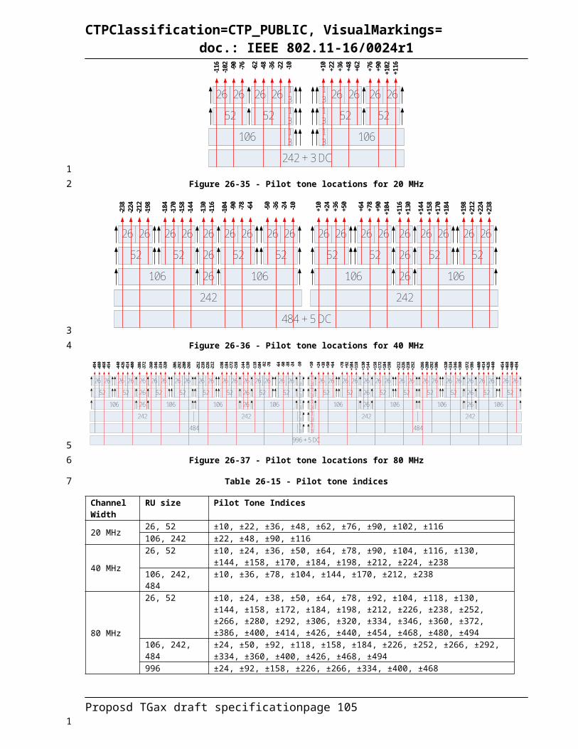
CTPClassification=CTP_PUBLIC, VisualMarkings=doc.: IEEE 802.11-16/0024r1
HELTF-500,500 = { -1, 0, 0, 0, -1, 0, 0, 0, +1, 0, 0, 0, +1, 0, 0, 0, +1, 0, 0, 0, +1, 0, 0, 0, +1, 0, 0, 0, -1, 0, 0, 0, -1, 0, 0, 0, -1, 0, 0, 0, +1, 0, 0, 0, +1, 0, 0, 0, -1, 0, 0, 0, -1, 0, 0, 0, +1, 0, 0, 0, -1, 0, 0, 0, +1, 0, 0, 0, -1, 0, 0, 0, -1, 0, 0, 0, -1, 0, 0, 0, -1, 0, 0, 0, -1, 0, 0, 0, -1, 0, 0, 0, +1, 0, 0, 0, +1, 0, 0, 0, -1, 0, 0, 0, -1, 0, 0, 0, +1, 0, 0, 0, -1, 0, 0, 0, +1, 0, 0, 0, -1, 0, 0, 0, -1, 0, 0, 0, -1, 0, 0, 0, -1, 0, 0, 0, -1, 0, 0, 0, +1, 0, 0, 0, +1, 0, 0, 0, -1, 0, 0, 0, -1, 0, 0, 0, +1, 0, 0, 0, -1, 0, 0, 0, +1, 0, 0, 0, -1, 0, 0, 0, +1, 0, 0, 0, +1, 0, 0, 0, +1, 0, 0, 0, +1, 0, 0, 0, +1, 0, 0, 0, -1, 0, 0, 0, -1, 0, 0, 0, +1, 0, 0, 0, +1, 0, 0, 0, -1, 0, 0, 0, +1, 0, 0, 0, -1, 0, 0, 0, +1, 0, 0, 0, -1, 0, 0, 0, -1, 0, 0, 0, -1, 0, 0, 0, -1, 0, 0, 0, +1, 0, 0, 0, -1, 0, 0, 0, -1, 0, 0, 0, -1, 0, 0, 0, -1, 0, 0, 0, -1, 0, 0, 0, -1, 0, 0, 0, +1, 0, 0, 0, +1, 0, 0, 0, +1, 0, 0, 0, -1, 0, 0, 0, -1, 0, 0, 0, +1, 0, 0, 0, +1, 0, 0, 0, -1, 0, 0, 0, +1, 0, 0, 0, -1, 0, 0, 0, +1, 0, 0, 0, +1, 0, 0, 0, +1, 0, 0, 0, +1, 0, 0, 0, +1, 0, 0, 0, +1, 0, 0, 0, -1, 0, 0, 0, -1, 0, 0, 0, +1, 0, 0, 0, +1, 0, 0, 0, -1, 0, 0, 0, +1, 0, 0, 0, -1, 0, 0, 0, +1, 0, 0, 0, +1, 0, 0, 0, +1, 0, 0, 0, +1, 0, 0, 0, -1, 0, 0, 0, +1, 0, 0, 0, +1, 0, 0, 0, -1, 0, 0, 0, -1, 0, 0, 0, +1, 0, 0, 0, -1, 0, 0, 0, +1, 0, 0, 0, -1, 0, 0, 0, +1, 0, 0, 0, +1, 0, 0, 0, +1, 0, 0, 0, +1, 0, 0, 0, +1, 0, 0, 0, -1, 0, 0, 0, -1, 0, 0, 0, +1, 0, 0, 0, +1, 0, 0, 0, -1, 0, 0, 0, +1, 0, 0, 0, -1, 0, 0, 0, +1, 0, 0, 0, -1, 0, 0, 0, -1, 0, 0, 0, -1, 0, 0, 0, -1, 0, 0, 0, +1, 0, 0, 0, -1, 0, 0, 0, +1, 0, 0, 0, -1, 0, 0, 0, -1, 0, 0, 0, 0, 0, 0, 0, -1, 0, 0, 0, +1, 0, 0, 0, +1, 0, 0, 0, -1, 0, 0, 0, -1, 0, 0, 0, +1, 0, 0, 0, +1, 0, 0, 0, -1, 0, 0, 0, -1, 0, 0, 0, +1, 0, 0, 0, +1, 0, 0, 0, -1, 0, 0, 0, +1, 0, 0, 0, -1, 0, 0, 0, +1, 0, 0, 0, +1, 0, 0, 0, +1, 0, 0, 0, +1, 0, 0, 0, +1, 0, 0, 0, +1, 0, 0, 0, -1, 0, 0, 0, -1, 0, 0, 0, +1, 0, 0, 0, +1, 0, 0, 0, -1, 0, 0, 0, +1, 0, 0, 0, -1, 0, 0, 0, +1, 0, 0, 0, +1, 0, 0, 0, +1, 0, 0, 0, +1, 0, 0, 0, +1, 0, 0, 0, -1, 0, 0, 0, -1, 0, 0, 0, +1, 0, 0, 0, +1, 0, 0, 0, -1, 0, 0, 0, +1, 0, 0, 0, -1, 0, 0, 0, +1, 0, 0, 0, -1, 0, 0, 0, -1, 0, 0, 0, -1, 0, 0, 0, -1, 0, 0, 0, -1, 0, 0, 0, +1, 0, 0, 0, +1, 0, 0, 0, -1, 0, 0, 0, -1, 0, 0, 0, +1, 0, 0, 0, -1, 0, 0, 0, +1, 0, 0, 0, -1, 0, 0, 0, +1, 0, 0, 0, +1, 0, 0, 0, +1, 0, 0, 0, +1, 0, 0, 0, -1, 0, 0, 0, +1, 0, 0, 0, -1, 0, 0, 0, -1, 0, 0, 0, +1, 0, 0, 0, -1, 0, 0, 0, -1, 0, 0, 0, +1, 0, 0, 0, +1, 0, 0, 0, +1, 0, 0, 0, -1, 0, 0, 0, -1, 0, 0, 0, +1, 0, 0, 0, +1, 0, 0, 0, -1, 0, 0, 0, +1, 0, 0, 0, -1, 0, 0, 0, +1, 0, 0, 0, +1, 0, 0, 0, +1, 0, 0, 0, +1, 0, 0, 0, +1, 0, 0, 0, +1, 0, 0, 0, -1, 0, 0, 0, -1, 0, 0, 0, +1, 0, 0, 0, +1, 0, 0, 0, -1, 0, 0, 0, +1, 0, 0, 0, -1, 0, 0, 0, +1, 0, 0, 0, +1, 0, 0, 0, +1, 0, 0, 0, +1, 0, 0, 0, -1, 0, 0, 0, +1, 0, 0, 0, +1, 0, 0, 0, -1, 0, 0, 0, -1, 0, 0, 0, +1, 0, 0, 0, -1, 0, 0, 0, +1, 0, 0, 0, -1, 0, 0, 0, +1, 0, 0, 0, +1, 0, 0, 0, +1, 0, 0, 0, +1, 0, 0, 0, +1, 0, 0, 0, -1, 0, 0, 0, -1, 0, 0, 0, +1, 0, 0, 0, +1, 0, 0, 0, -1, 0, 0, 0, +1, 0, 0, 0, -1, 0, 0, 0, +1, 0, 0, 0, -1, 0, 0, 0, -1, 0, 0, 0, -1, 0, 0, 0, -1, 0, 0, 0, +1, 0, 0, 0, -1, 0, 0, 0, +1, 0, 0, 0, -1, 0, 0, 0, -1, 0, 0, 0, -1, 0, 0, 0, +1, 0, 0, 0, +1}
(26-44)
In an 80 MHz transmission, the 2x HE-LTF sequence transmitted is given by Equation (26-45).
HELTF-500,500 = {+1, 0, +1, 0, -1, 0, +1, 0, +1, 0, +1, 0, -1, 0, +1, 0, +1, 0, +1, 0, +1, 0, -1, 0, -1, 0, -1, 0, +1, 0, -1, 0, -1, 0, +1, 0, +1, 0, -1, 0, +1, 0, +1, 0, +1, 0, -1, 0, -1, 0, -1, 0, -1, 0, +1, 0, +1, 0, +1, 0, +1, 0, -1, 0, +1, 0, +1, 0, +1, 0, -1, 0, +1, 0, -1, 0, -1, 0, +1, 0, -1, 0, -1, 0, -1, 0, +1, 0, +1, 0, -1, 0, -1, 0, -1, 0, +1, 0, -1, 0, -1, 0, +1, 0, -1, 0, +1, 0, +1, 0, -1, 0, +1, 0, +1, 0, -1, 0, +1, 0, -1, 0, -1, 0, -1, 0, +1, 0, -1, 0, -1, 0, -1, 0, -1, 0, +1, 0, -1, 0, -1, 0, +1, 0, +1, 0, -1, 0, +1, 0, +1, 0, +1, 0, -1, 0, -1, 0, -1, 0, -1, 0, +1, 0, -1, 0, +1, 0, +1, 0, +1, 0, -1, 0, +1, 0, +1, 0, +1, 0, +1, 0, -1, 0, -1, 0, -1, 0, +1, 0, +1, 0, +1, 0, -1, 0, -1, 0, +1, 0, +1, 0, +1, 0, -1, 0, +1, 0, +1, 0, -1, 0, +1, 0, -1, 0, -1, 0, -1, 0, -1, 0, +1, 0, -1, 0, -1, 0, -1, 0, +1, 0, -1, 0, +1, 0, +1, 0, -1, 0, +1, 0, +1, 0, -1, 0, -1, 0, -1, 0, +1, 0, -1, 0, -1, 0, -1, 0, +1, 0, -1, 0, +1, 0, +1, 0, -1, 0, +1, 0, +1, 0, +1, 0, -1, 0, -1, 0, +1, 0, +1, 0, +1, 0, -1, 0, +1, 0, +1, 0, -1, 0, +1, 0, -1, 0, -1, 0, +1, 0, -1, 0, +1, 0, +1, 0, +1, 0, -1, 0, +1, 0, +1, 0, +1, 0, +1, 0, -1, 0, -1, 0, -1, 0, +1, 0, -1, 0, -1, 0, +1, 0, +1, 0, -1, 0, +1, 0, +1, 0, +1, 0, -1, 0, -1, 0, -1, 0, -1, 0, +1, 0, +1, 0, +1, 0, -1, 0, -1, 0, -1, 0, -1, 0, +1, 0, -1, 0, -1, 0, -1, 0, +1, 0, -1, 0, +1, 0, +1, 0, +1, 0, -1, 0, -1, 0, +1, 0, +1, 0, +1, 0, -1, 0, +1, 0, +1, 0, -1, 0, +1, 0, -1, 0, -1, 0, -1, 0, -1, 0, +1, 0, -1, 0, -1, 0, -1, 0, +1, 0, -1, 0, +1, 0, +1, 0, -1, 0, +1, 0, +1, 0, -1, 0, +1, 0, +1, 0, -1, 0, -1, 0, +1, 0, -1, 0, -1, 0, -1, 0, +1, 0, +1, 0, +1, 0, +1, 0, -1, 0, +1, 0, -1,
(26-45)
Proposd TGax draft specification page 105
1
1

CTPClassification=CTP_PUBLIC, VisualMarkings=doc.: IEEE 802.11-16/0024r1
0, -1, 0, -1, 0, +1, 0, -1, 0, -1, 0, -1, 0, -1, 0, +1, 0, +1, 0, +1, 0, +1, 0, -1, 0, -1, 0, -1, 0, +1, 0, +1, 0, +1, 0, 0, 0, 0, 0, 0, 0, +1, 0, -1, 0, -1, 0, +1, 0, +1, 0, -1, 0, +1, 0, -1, 0, -1, 0, -1, 0, +1, 0, +1, 0, +1, 0, +1, 0, -1, 0, +1, 0, +1, 0, +1, 0, -1, 0, +1, 0, -1, 0, -1, 0, -1, 0, -1, 0, +1, 0, +1, 0, +1, 0, -1, 0, +1, 0, +1, 0, -1, 0, -1, 0, +1, 0, -1, 0, -1, 0, +1, 0, -1, 0, -1, 0, +1, 0, -1, 0, +1, 0, +1, 0, +1, 0, -1, 0, +1, 0, +1, 0, +1, 0, +1, 0, -1, 0, +1, 0, -1, 0, -1, 0, +1, 0, -1, 0, -1, 0, -1, 0, +1, 0, +1, 0, -1, 0, -1, 0, -1, 0, +1, 0, -1, 0, +1, 0, +1, 0, +1, 0, -1, 0, +1, 0, +1, 0, +1, 0, +1, 0, -1, 0, -1, 0, -1, 0, +1, 0, +1, 0, +1, 0, +1, 0, -1, 0, -1, 0, -1, 0, +1, 0, -1, 0, -1, 0, +1, 0, +1, 0, -1, 0, +1, 0, +1, 0, +1, 0, -1, 0, -1, 0, -1, 0, -1, 0, +1, 0, -1, 0, -1, 0, -1, 0, +1, 0, -1, 0, +1, 0, +1, 0, -1, 0, +1, 0, -1, 0, -1, 0, +1, 0, -1, 0, -1, 0, -1, 0, +1, 0, +1, 0, -1, 0, -1, 0, -1, 0, +1, 0, -1, 0, -1, 0, +1, 0, -1, 0, +1, 0, +1, 0, +1, 0, -1, 0, +1, 0, +1, 0, +1, 0, -1, 0, +1, 0, -1, 0, +1, 0, +1, 0, -1, 0, +1, 0, -1, 0, -1, 0, -1, 0, +1, 0, -1, 0, -1, 0, -1, 0, -1, 0, +1, 0, -1, 0, +1, 0, +1, 0, -1, 0, +1, 0, +1, 0, +1, 0, -1, 0, -1, 0, +1, 0, +1, 0, +1, 0, -1, 0, -1, 0, -1, 0, +1, 0, +1, 0, +1, 0, +1, 0, -1, 0, +1, 0, +1, 0, +1, 0, -1, 0, +1, 0, -1, 0, -1, 0, -1, 0, -1, 0, +1, 0, +1, 0, +1, 0, -1, 0, +1, 0, +1, 0, -1, 0, -1, 0, +1, 0, -1, 0, -1, 0, -1, 0, -1, 0, +1, 0, -1, 0, -1, 0, -1, 0, +1, 0, -1, 0, +1, 0, +1, 0, -1, 0, +1, 0, +1, 0, -1, 0, +1, 0, -1, 0, -1, 0, +1, 0, -1, 0, -1, 0, -1, 0, +1, 0, +1, 0, -1, 0, -1, 0, -1, 0, +1, 0, -1, 0, -1, 0, +1, 0, -1, 0, +1, 0, +1, 0, +1, 0, -1, 0, +1, 0, +1, 0, +1, 0, +1, 0, -1, 0, -1, 0, -1, 0, -1, 0, +1, 0, +1, 0, +1, 0, -1, 0, +1, 0, +1, 0, -1, 0, -1, 0, +1, 0, -1, 0, -1, 0, -1, 0, +1, 0, +1, 0, +1, 0, +1, 0, -1, 0, +1, 0, +1, 0, +1, 0, -1, 0, +1, 0, +1}
In an 80 MHz transmission, the 4x HE-LTF sequence transmitted is given by Equation (26-46).
HELTF-500,500 = {+1, +1, -1, +1, -1, +1, -1, -1, -1, +1, -1, -1, -1, +1, +1, -1, +1, +1, +1, +1, +1, -1, -1, +1, +1, +1, +1, -1, +1, -1, +1, -1, -1, +1, +1, -1, +1, +1, +1, -1, -1, +1, -1, -1, -1, -1, +1, +1, +1, -1, -1, -1, -1, -1, -1, +1, +1, +1, +1, +1, +1, -1, +1, +1, +1, -1, +1, +1, -1, -1, -1, +1, -1, +1, -1, -1, +1, +1, -1, +1, -1, +1, +1, +1, +1, +1, -1, -1, +1, +1, +1, -1, +1, +1, -1, -1, -1, +1, -1, +1, +1, -1, +1, +1, -1, +1, -1, -1, +1, +1, +1, +1, -1, -1, +1, +1, +1, +1, +1, -1, +1, +1, -1, -1, -1, +1, -1, -1, -1, +1, -1, +1, -1, +1, +1, -1, +1, -1, +1, -1, +1, +1, +1, -1, +1, +1, +1, -1, -1, +1, -1, -1, -1, -1, -1, +1, +1, -1, -1, -1, -1, +1, -1, +1, -1, +1, +1, -1, -1, +1, -1, -1, -1, +1, +1, -1, +1, +1, +1, +1, -1, -1, -1, +1, +1, +1, +1, -1, +1, +1, +1, +1, +1, +1, +1, -1, +1, +1, +1, -1, +1, +1, -1, -1, -1, +1, -1, +1, -1, -1, +1, +1, -1, +1, -1, +1, +1, +1, +1, +1, -1, -1, +1, +1, +1, -1, +1, +1, -1, -1, -1, +1, -1, +1, +1, -1, +1, +1, -1, +1, -1, -1, +1, -1, +1, -1, +1, -1, +1, +1, +1, -1, +1, +1, +1, -1, -1, +1, -1, -1, -1, -1, -1, +1, +1, -1, -1, -1, -1, +1, -1, +1, -1, +1, +1, -1, -1, +1, -1, -1, -1, +1, +1, -1, +1, +1, +1, +1, -1, -1, -1, +1, +1, +1, +1, -1, +1, -1, -1, -1, -1, -1, -1, +1, -1, -1, -1, +1, -1, -1, +1, +1, +1, -1, +1, -1, +1, +1, -1, -1, +1, -1, +1, -1, -1, -1, -1, -1, +1, +1, -1, -1, -1, +1, -1, -1, +1, +1, +1, -1, +1, -1, -1, +1, -1, -1, +1, -1, +1, +1, +1, +1, +1, +1, -1, -1, +1, +1, +1, +1, +1, -1, +1, +1, -1, -1, -1, +1, -1, -1, -1, +1, -1, +1, -1, +1, +1, -1, +1, -1, +1, -1, +1, +1, +1, -1, +1, +1, +1, -1, -1, +1, -1, -1, -1, -1, -1, +1, +1, -1, -1, -1, -1, +1, -1, +1, -1, +1, +1, -1, -1, +1, -1, -1, -1, +1, +1, -1, +1, +1, +1, +1, -1, -1, -1, +1, +1, +1, +1, -1, -1, +1, +1, +1, +1, +1, +1, -1, +1, +1, +1, -1, +1, +1, -1, -1, -1, +1, -1, +1, -1, -1, +1, +1, -1, +1, -1, +1, +1, +1, +1, +1, -1, -1, +1, +1, +1, -1, +1, +1, -1, -1, -1, +1, -1, +1, +1, -1, +1, +1, -1, +1, -1, -1, -1, +1, -1, +1, -1, -1, -1, -1, +1, +1, +1, -1, -1, +1, 0, 0, 0, 0, 0, +1, -1, -1, -1, -1, -1, -1, +1, -1, +1, +1, -1, -1, +1, +1, -1, +1, -1, +1, +1, -1, -1, +1, -1, +1, -1, -1, -1, +1, +1, -1, +1, +1, +1, -1, +1, +1, +1, +1, +1, +1, +1, -1, +1, -1, -1, +1, -1, -1, +1, -1, +1, +1, +1, -1, -1, +1, -1, -1, -1, +1, +1, -1, -1, -1, -1, -1, +1, -1, -1, -1, -1, -1, +1, +1, -1, -1, -1, -1, -1, +1, -1, -1, +1, +1, +1, -1, +1, +1, +1, -1, +1, -1, +1, -1, -1, -1, -1, -1, +1, +1, +1, -1, -1, -1, -1, +1, -1, -1, +1, +1, +1, -1, +1, +1, -1, -1, +1, -1, +1, -1, -1, -1, -1, -1, -1, -1, +1, +1, -1, -1, -1, +1, -1, -1, +1, +1, +1, -1, +1, -1, -1, +1, -1, -1, +1, -1, +1, +1, +1, -1, +1, -1, -1, +1, +1, -1, +1, -1, +1, +1, +1, -1, -1, +1, -1, -1, -1, +1, -1, -1, -1, -1, -1, -1, -1, +1, -1, +1, +1, -1, +1, +1, -1, +1, -1, -1, -1, +1, +1, -1, +1, +1, +1, -1, -1, +1, +1, +1, +1, +1, -1, +1, -1, -1, -1, -1, +1, +1, -1, -1, -1, -1, -1, +1, -1, -1, +1, +1, +1, -1, +1, +1, +1, -1, +1, -1, +1, -1, -1, -1, -1, -1, +1, +1, +1, -1, -1, -1, -1, +1, -1, -1, +1, +1, +1, -1, +1, +1, -1, -1, +1, -1, +1, -1, +1, +1, +1, -1, +1, -1, -1, +1, +1, -1, +1, -1, +1, +1, +1, -1, -1, +1, -1, -1, -1, +1, -1, -1, -1, -1, -1, -1, -1, +1, -1, +1, +1, -1, +1, +1, -1, +1, -1, -1, -1, +1, +1, -1, +1, +1, +1, -1, -1, +1, +1, +1, +1, +1, -1, +1, +1, +1, +1, +1, -1, -1, +1, +1, +1, +1, +1, -1, +1, +1, -1, -1, -1, +1, -1, -1, -1, +1, -1, +1, -1, +1, +1, +1, +1, +1, -1, -1, -1, +1, +1, +1, +1, -1, +1, +1, -1, -1, -1, +1, -1, -1, +1, +1, -1, +1, -1, +1, -1, -1, -1, -1, -1, -1, +1, +1, -1, -1, -1, +1, -1, -1, +1, +1,
(26-46)
Proposd TGax draft specification page 106
1
1
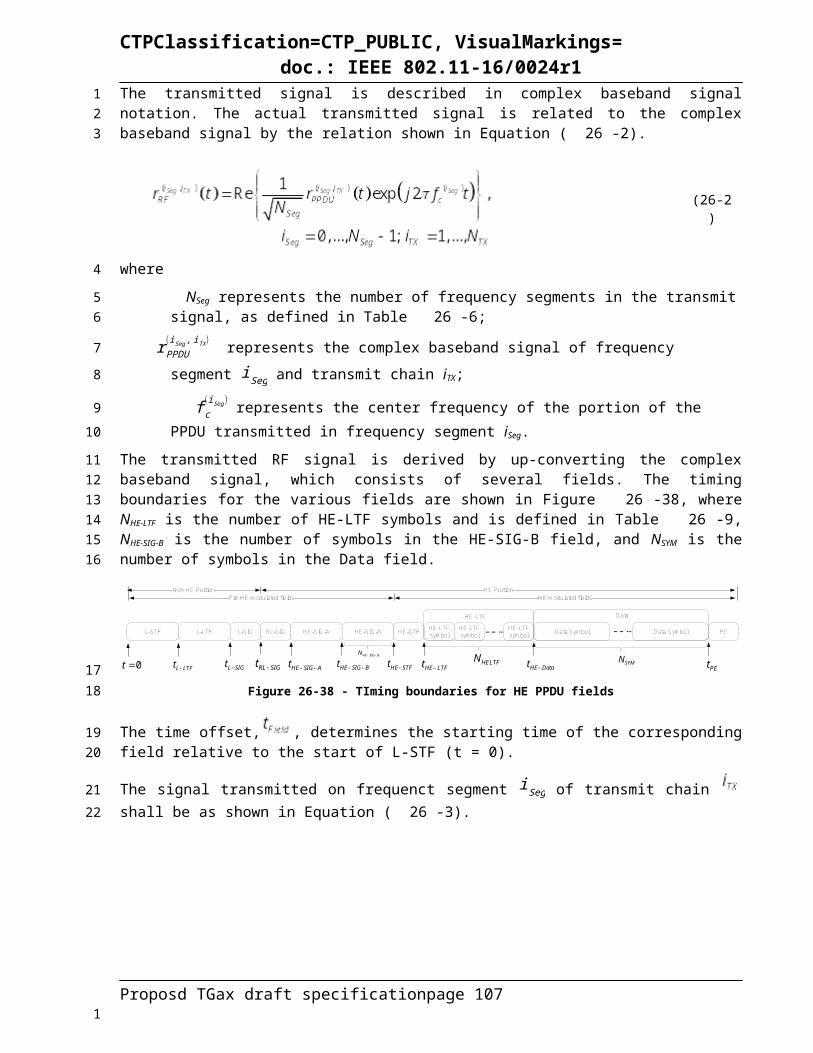
CTPClassification=CTP_PUBLIC, VisualMarkings=doc.: IEEE 802.11-16/0024r1
+1, -1, +1, -1, -1, +1, -1, -1, +1, -1, +1, -1, +1, -1, +1, -1, -1, +1, +1, -1, +1, -1, +1, +1, +1, -1, -1, +1, -1, -1, -1, +1, -1, -1, -1, -1, -1, -1, -1, +1, -1, +1, +1, -1, +1, +1, -1, +1, -1, -1, -1, +1, +1, -1, +1, +1, +1, -1, -1, +1, +1, +1, +1, +1, -1, +1, -1, -1, -1, -1, +1, +1, -1, -1, -1, -1, -1, +1, -1, -1, +1, +1, +1, -1, +1, +1, +1, -1, +1, -1, +1, -1, -1, -1, -1, -1, +1, +1, +1, -1, -1, -1, -1, +1, -1, -1, +1, +1, +1, -1, +1, +1, -1, -1, +1, -1, +1, -1, +1}
In a 160 MHz transmission, the 1x HE-LTF sequence transmitted is given by Equation (26-47).
HELTF-1012,1012 = { 1x LTF80MHz_primary, zeros(1,23), 1x LTF80MHz_secondary } (26-47)
where 1x LTF80MHz_primary = {L-LTF80MHz_1x, 0, R-LTF80MHz_1x}, 1x LTF80MHz_ secondary = {L-LTF80MHz_1x, 0, (-1)*R-LTF80MHz_1x}.
In a 160 MHz transmission, the 2x HE-LTF sequence transmitted is given by Equation (26-48).
HELTF-1012,1012 = { 2x LTF80MHz_primary, zeros(1,23), 2x LTF80MHz_secondary } (26-48)
where
2x LTF80MHz_primary = { {1st 242-RU}, {2nd 242-RU}, {central 26-RU}, {3rd 242-RU}, {4th 242-RU}
(26-49)
2x LTF80MHz_secondary = { {1st 242-RU}, (-1)*{2nd 242-RU}, {central 26-RU}, {3rd 242-RU}, (-1)*{4th
242-RU} }(26-50)
In a 160 MHz transmission, the 4x HE-LTF sequence transmitted is given by Equation (26-51).
HELTF-1012,1012 = { 4x LTF80MHz_primary, zeros(1,23), 4x LTF80MHz_secondary } (26-51)
where
4x LTF80MHz_primary = {L-LTF80MHz_4x, 0, R-LTF80MHz_4x} (26-52)
4x LTF80MHz_ secondary = {L-LTF80MHz_4x, 0, (-1)*R-LTF80MHz_4x} (26-53)
For a noncontiguous 80+80 MHz transmission, the 1x HE-LTF sequence is given by Equation (26-54).
HELTF80+80MHz = { 1x LTF80MHz_primary, 1x LTF80MHz_secondary } (26-54)
For a noncontiguous 80+80 MHz transmission, the 2x HE-LTF sequence is given by Equation (26-55).
HELTF80+80MHz = { 2x LTF80MHz_primary, 2x LTF80MHz_secondary } (26-55)
For a noncontiguous 80+80 MHz transmission, the 4x HE-LTF sequence is given by Equation (26-56).
HELTF80+80MHz = { 4x LTF80MHz_primary, 4x LTF80MHz_secondary } (26-56)
The generation of the time domain HE-LTF symbols per frequency segment in an HE SU PPDU, HE MU PPDU, HE extended range SU PPDU, HE trigger-based PPDU using single stream pilots is shown in
Figure 26-46 where AVHT -LTFk
is given by Equation (26-57).
Proposd TGax draft specification page 107
1
23
4
5
6
7
8
9
10
1112
13
1

CTPClassification=CTP_PUBLIC, VisualMarkings=doc.: IEEE 802.11-16/0024r1
CSD
IDFTX
X
. . .
. . .
. . .
IDFT
1,
kHELTF n
A
, , ,STS r total
kHELTF N n
A
, ,1: STS r total
kHELTF N
Q
kHELTF
Figure 26-46 – Generation of HE-LTF symbols per frequency segment in an HE SU PPDU, HE MU PPDU, HE extended range SU PPDU, and HE trigger-based PPDU using single stream pilots
The generation of time domain symbol of 1x HE-LTF is equivalent to modulating every 4 tones in an OFDM symbol of 12.8 µs excluding GI, and then only transmit the first ¼ of the OFDM symbol in the time domain, as shown in Figure 26-47.
Insert GI and
Window
Analog and RF
...
Mod
ulat
e ev
ery
4 to
nes
AH
ELT
F CSD per STS
CSD per STS
...
IDFT
IDFT
IDFTTruncate ¼ of time symbol
...
Truncate ¼ of time symbol
Truncate ¼ of time symbol
Insert GI and
Window
Analog and RF
Insert GI and
Window
Analog and RF
... ...
Spa
tial M
appi
ng
...
Figure 26-47 - Generation of 1x HE-LTF symbols per frequency segment
The generation of time domain symbol of 2x HE-LTF is equivalent to modulating every other tone in an OFDM symbol of 12.8 µs excluding GI, and then only transmit the first half of the OFDM symbol in time domain, as shown in Figure 26-48.
Insert GI and
Window
Analog and RF
...
Mod
ulat
e ev
ery
2 to
nes
AH
ELT
F CSD per STS
CSD per STS
...
IDFT
IDFT
IDFTTruncate ½ of time symbol
...
Truncate ½ of time symbol
Truncate ½ of time symbol
Insert GI and
Window
Analog and RF
Insert GI and
Window
Analog and RF
... ...
Spa
tial M
appi
ng
...
Figure 26-48 - Generation of 2x HE-LTF symbols per frequency segment
is given by Equation (26-57).
Proposd TGax draft specification page 108
123
456
78
91011
1213
14
1

CTPClassification=CTP_PUBLIC, VisualMarkings=doc.: IEEE 802.11-16/0024r1
(26-57)
where KPilot is the set of subcarrier indices for the pilot tones as defined in 25.x (xx).
is a matrix whose elements are defined in Equation (26-58).
(26-58)
is defined in (26-59).
(26-59)
where P4is defined in Equation (20-17), P6is defined in Equation (22-45), and P8is defined in Equation (22-46).
In an HE SU PPDU, HE MU PPDU, HE extended range SU PPDU and HE trigger-based PPDU using single stream pilots, the time domain representation of the waveform transmitted on frequency segment iSeg of transmit chain iTX shall be as described by Equation (26-60).
(26-60)
where
αr is the power boost factor for the r-th RU, where α r∈ [TB D1 ,TB D2 ]ηEXT is an PPDU format dependent scaling factor, with the following value
ηEXT={√2 , HE extended range SU PPDU1 , otherwise
has the value given in Table 25-xx (Tone scaling factor and guard interval duration values for PHY fields)
is given in 26.3.9.2 (Cyclic shift for Pre-HE modulated fields)
is defined in 25.xx (Transmission in HE format)
is defined in Equation (26-57)
Kr is the set of subcarrier indices for the tones in the r-th RU as defined in 25.x.ηHELTF is the power scaling factor as defined in (25-xx)
Proposd TGax draft specification page 109
1
2
3
45
678
9
10
11
12
1314
15
16
17
18
19
1

CTPClassification=CTP_PUBLIC, VisualMarkings=doc.: IEEE 802.11-16/0024r1
26.3.10 Data field26.3.10.1 GeneralThe number of OFDM symbols in the Data field is determined by the Length field in L-SIG (see Equation (25-x)), the preamble duration and the setting of the CP+LTF Size field in HE-SIG-A (see 25.3.9.2.4.x HE-SIG-A definition). Data symbols in an HE PPDU shall use a DFT period of 12.8 µs and subcarrier spacing of 78.125 kHz. Data symbols in an HE PPDU shall support guard interval durations of 0.8 µs, 1.6 µs and 3.2 µs. HE PPDUs shall have single stream pilots in the Data field. In UL MU-MIMO transmissions, all streams use the same pilot sequence. The Data field in UL MU transmissions shall immediately follow the HE-LTF section.
When BCC encoding is used, the Data field shall consist of the SERVICE field, the PSDU, the tail bits, the post-FEC padding bits and the packet extension (bits for SU and bits for each user u in MU). When LDPC encoding is used, the Data field shall consist of the SERVICE field, the PSDU, the post-FEC padding bits and the packet extension. No tail bits are present when LDPC encoding is used.
The Data field of the HE PPDU contains data for one or more users.
26.3.10.1.1 Pre-FEC encoding processA two-step padding process is applied on all HE PPDUs. A pre-FEC padding with both MAC and PHY padding is applied before conducting FEC coding, and a post-FEC PHY padding is applied on the FEC encoded bits.
The pre-FEC padding may pad torward 4 possible boundaries in the last one (in the case of non STBC), or two (in the case of STBC) OFDM symbols of a HE PPDU, the 4 possible boundaries participate the FEC output bit stream of the last OFDM symbol(s) into 4 symbol segments. The 4 possible boundaries are represented by a parameter a, called a-factor.
Figure 26-49 illustrates these 4 possible symbol segments in the last OFDM symbol of a non STBC case, and the general padding process assuming the desired pre-FEC padding boundary, a-factor, is 1. In the case of STBC, the FEC output bits and post-FEC padding bits as shown in Figure 26-50, are modulated into the last two OFDM symbols by STBC encoding, each with the same number of effective symbol segments, a-factor, being 1.
FEC output bits
Bit stream in the last OFDM symbola = 1
Excess information bits
Pre-FEC padding bits
Scrambler
FEC post-FEC padding bits
NCBPS bitsNCBPS.LAST bits
Figure 26-49 - HE PPDU padding process in the last OFDM symbol (non STBC) when a = 1
Proposd TGax draft specification page 110
1
2
3456789
10
11121314
15
16
171819
20212223
2425262728
29
30
1
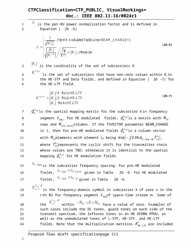
CTPClassification=CTP_PUBLIC, VisualMarkings=doc.: IEEE 802.11-16/0024r1
FEC output bitsBit stream in the second
last OFDM symbol
a = 1
Excess information bits
Pre-FEC padding bits
Scrambler
FEC
NCBPS bitsNCBPS.LAST bits
post-FEC padding bits
FEC output bits
post-FEC padding bits
Bit stream in the last OFDM symbol
1st half
2nd half
Figure 26-50 – HE PPDU padding process in the last OFDM symbol (STBC) when a = 1
The pre-FEC padding process is described in this subclause, and the encoding and post-FEC padding process are described in 26.3.10.3. While this subclause describes the pre-FEC padding processing of an SU transmission, its extension to MU transmission is described in 25.3.10.3.4 (Encoding Process for HE MU PPDUs).
In an HE SU PPDU transmission, the transmitter first computes the number of excess bits in the last OFDM symbol(s). Specifically, for HE SU PPDU with BCC encoding, the number of excess bits is calculated based on Equation (26-61).
(26-61)
where
mSTBC is 2 when STBC is used, and 1 otherwise;
APEP_LENGTH is the TXVECTOR parameter APEP_LENGTH.
For a HE SU PPDU with LDPC encoding, the number of excess bits is calculated based on Equation (26-62):
(26-62)
Then based on NExcess, compute the initial number of symbol segments in the last OFDM symbol(s), a-factor value or ainit, as shown in Equation (26-63):
(26-63)
where
N DBPS. SHORT=NCBPS .SHORT . R , in which R is the coding rate, and
NCBPS . SHORT=N SD .SHORT . NSS .N BPSCS;
Proposd TGax draft specification page 111
12
3456
789
10
11
12
1314
1516
17
18
19
1

CTPClassification=CTP_PUBLIC, VisualMarkings=doc.: IEEE 802.11-16/0024r1
The parameter NSD .SHORT values for different RU sizes are as shown in Table 26-25.
Table 26-25 - N SD .SHORT values
RU Size NSD.SHORT
DCM = 0 DCM = 126 6 2 (TBD)52 12 6 (TBD)
106 24 12 (TBD)242 60 30 (TBD)484 120 60 (TBD)996 240 120 (TBD)
996x2 492 246 (TBD)
Given the a init values, the initial number of data bits per symbol and the initial number of coded bits per symbol in the last OFDM symbol(s) are defined in Equation (26-64):
(26-64)
For a HE SU PPDU with BCC encoding, the number of pre-FEC pad bits is calculated using Equation (26-65).
(26-65)
where N SYM . init is defined as in Equation (26-68) for BCC encoding, and Equation (26-73) for LDPC encoding.
For a HE SU PPDU with LDPC encoding, the number of pre-FEC pad bits is calculated using Equation (26-66).
(26-66)
Among the pre-FEC padding bits, the MAC delivers a PSDU that fills the available octets in the Data field of the HE PPDU, toward the desired pre-FEC padding boundary, represented by a init value, in the the last OFDM symbol(s). The PHY then determines the number of pad bits to add and appends them to the PSDU. The number of pre-FEC pad bits added by PHY will always be 0 to 7. The procedure is defined in Equation (26-67).
(26-67)
26.3.10.2 SERVICE fieldThe SERVICE field of HE PPDU is as shown in Table 26-26.
Proposd TGax draft specification page 112
1
2
34
56
78
910
1112131415
16
17
18
1

CTPClassification=CTP_PUBLIC, VisualMarkings=doc.: IEEE 802.11-16/0024r1
Table 26-26 – SERVICE field
Bits Field DescriptionB0-B6 Scrambler Initialization Set to 0B7-B15 Reserved Set to 0
26.3.10.3 CodingThe Data field shall be encoded using either the binary convolutional code (BCC) defined in 26.3.10.3.1 or the low density parity check (LDPC) code defined in 25.3.10.3.2 (LDPC coding). The encoder is selected by the Coding field in HE-SIG-A in an HE SU PPDU or an HE extended range SU PPDU, or HE-SIG-B per-user subfield(s) in a HE MU PPDU, as defined in 26.3.9.7 and 26.3.9.8 respectively.
When conducting BCC FEC encoding for an HE PPDU, the number of encoders is always 1.
LDPC is the only FEC coding scheme in the HE PPDU Data field for a 484-RU, a 996-RU or a 996x2-RU. Support of BCC code is limited to less than or equal to four spatial streams (per user in case of MU-MIMO), and is mandatory (for both transmit and receive) for RU sizes less than or equal to a 242-RU. Support of LDPC code (for both transmit and receive) is mandatory for HE STAs declaring support for at least one of HE 40/80/160/80+80 SU PPDU bandwidths, or for HE STAs declaring support for more than 4 spatial streams, according to HE capabilities field as defined in clause 8.4.2.1 (HE Capabilities Element). Otherwise, support of LDPC code for either transmit or receive is optional.
26.3.10.3.1 Binary convolutional coding and puncturingThe information bits and pre-FEC padding bits of user u are encoded by a rate R = ½ convolutional encoder defined in 18.3.5.6 (Convolutional encoder). After encoding, the encoded data is punctured by the method defined in 18.3.5.6 (Convolutional encoder) (except for rate 5/6), to achieve the rate selected by the modulation and coding scheme. In the case that rate 5/6 coding is selected, the puncturing scheme will be the same as described in 20.3.11.6 (Binary convolutional coding and puncturing).
The initial number of OFDM symbols in the Data field with BCC encoding in a HE SU PPDU is calculated as in Equation (26-68),
(26-68)
For a HE SU PPDU with BCC encoding,
(26-69)
and
(26-70)
The number of coded bits per symbol in the last OFDM symbol(s) of a HE SU PPDU is
(26-71)
26.3.10.3.2 LDPC codingFor a HE SU PPDU using LDPC coding to encode the Data field, the LDPC code and encoding process described in 20.3.11.7 (LDPC codes) shall be used with the following modifications. First, all bits in the
Proposd TGax draft specification page 113
1
2
3
4567
8
9101112131415
16
1718192021
2223
24
25
26
27
2829
1

CTPClassification=CTP_PUBLIC, VisualMarkings=doc.: IEEE 802.11-16/0024r1
Data field including the scrambled SERVICE, PSDU, and pre-FEC pad bits are encoded. Thus, Npld for HE PPDUs shall be computed using Equation (26-72) instead of Equation (20-35).
(26-72)
where
N SYM . init is given by Equation (26-73):
(26-73)
Following the calculation of N pld, Navbitsshall be computed using (26-74) instead of Equation (20-36).
(26-74)
In addition, in step d) of LDPC encoding process as described in clause 20.3.11.7.5 (LDPC PPDU encoding process) , if the following condition is met:
is true OR if
is true,
then the LDPC Extra OFDM Symbol field of HE-SIG-A shall be set to 1, and increment Navbits by the following Equation (26-75) instead of Equations (20-39), followed by recomputing N punc as in Equation (20-40):
(26-75)
and then update a and NSYM values by the following Equation (26-76):
(26-76)
If in step d) of LDPC encoding process as described in clause 20.3.11.7.5 (LDPC PPDU encoding process), the above mentioned condition is not met, then the LDPC Extra OFDM Symbol field of HE-SIG-A shall be set to 0, and:
(26-77)
With the final a-factor value a, update the NCBPS of the last symbol as:
(26-78)
Proposd TGax draft specification page 114
12
3
4
5
67
8
9
101112
13
141516
17
1
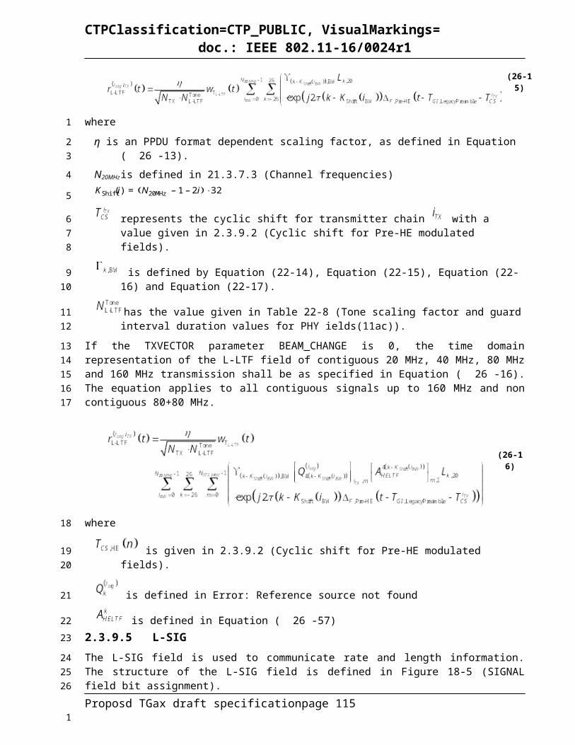
CTPClassification=CTP_PUBLIC, VisualMarkings=doc.: IEEE 802.11-16/0024r1
LDPC codes used in HE MU PPDUs shall also follow the definitions in 20.3.11.7 (LDPC codes). Refer to 25.3.10.3.4 (Encoding process for HE MU PPDUs) for a description of the LDPC encoding process for HE MU PPDUs.
26.3.10.3.3 Post-FEC paddingThe number of post-FEC padding bits in each of the last mSTBC symbol(s) is computed by:
(26-79)
NPAD.POST-FEC bits with arbitrary 0 or 1 values (TBD) are appended after the FEC output bits in each of the last mSTBCOFDM symbols.
26.3.10.3.4 Encoding process for an HE MU PPDUFor an HE MU PPDU, all the users shall use a common a-factor value and a common N SYM value. The padding process is described as follows:
First compute initial a-factor value (a init ,u) for each user u using Equation (26-63), and the initial number of OFDM symbols (N init ,u) for each user u using Equation (26-68) if user u is BCC encoded, or Equation (26-73) if user u is LDPC encoded. Among all the users, derive the user index with the longest encoded packet duration, as in Equation (26-80):
(26-80)
where mSTBC is the common STBC setting among all the users, as described in 26.3.10.8.
Then the common a init and N init values among all the users are derived by Equation (26-81):
(26-81)
Update each user’s initial number of coded bits in its last symbol as below:
(26-82)
For each user with LDPC encoding, the number of pre-FEC padding bits is computed as in Equation (26-83):
(26-83)
For each user with LDPC encoding, the parameters N pld ,u and N avbits , uare computed using Equations (26-84) and (26-85) respectively:
(26-84)
Proposd TGax draft specification page 115
123
4
5
67
8
910
11121314
15
16
17
1819
2021
1
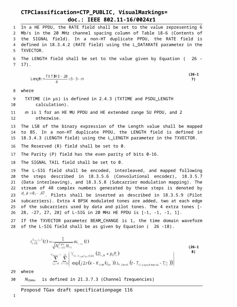
CTPClassification=CTP_PUBLIC, VisualMarkings=doc.: IEEE 802.11-16/0024r1
(26-85)
Each user with LDPC encoding continue LDPC encoding process as in clause 20.3.11.7.5 (LDPC PPDU encoding process) starting with the parameters N pld ,u and Navbits , u. If there is at least one user with LDPC encoding, where step d) of its LDPC encoding process of clause 20.3.11.7.5 (LDPC PPDU encoding process), meets the following condition:
is true OR if
is true, where N punc , u, NCW ,u, LLDPC ,u, N shrt ,u are the LDPC encoding paraters for user u, as defined in 20.3.11.7.5 (LDPC PPDU encoding process), and Ru is the coding rate of user u, then the LDPC Extra symbol bit in HE-SIG-A shall be set to 1, and all the users with LDPC encoding shall increment Navbits and recomputed Npunc, by the following two equations once:
(26-86)
(26-87)
Update the common a-factor and NSYM values for all users by the following equation:
(26-88)
Note that users with BCC encoding shall also use the common N SYM and a parameters as in Equation (26-76).
If among all the users with LDPC encoding, in step d) of clause 20.3.11.7.5 (LDPC PPDU encoding process), the above mentioned condition is not met, or if all the users in the HE MU PPDU are BCC encoded, then the LDPC Extra symbol bit in HE-SIG-A shall be set to 0, and:
(26-89)
Update the NCBPS and NDBPS of the last symbol for each user as:
(26-90)
For the users with BCC encoding, the number of pre-FEC padding bits is shown in Equation (26-91).
(26-91)
Proposd TGax draft specification page 116
1234
5
6789
10
1112
131415
16
17
1

CTPClassification=CTP_PUBLIC, VisualMarkings=doc.: IEEE 802.11-16/0024r1
For each user with either LDPC or BCC encoding, the number of post-FEC padding bits in each of the last mSTBC symbol(s) is computed as in Equation (26-92):
(26-92)
26.3.10.3.5 Encoding process for an HE trigger-based PPDUThe AP indicates the common NSYM, a-factor, STBC indication and LDPC Extra Symbol in the Trigger frame.
For an HE trigger-based PPDU with BCC encoding, follow the HE SU PPDU padding and encoding process as introduced in clause 25.3.10.1.1 (pre-FEC padding process), clause 25.3.10.3.1 (Binary convolutional coding and puncturing), and 25.3.10.3.3 (Post-FEC Padding), with initial parameters setting to N SYM . init=NSYM, and a init=a, where N SYM and a are the common number of symbols and a-factor parameters indicated in the Trigger frame, respectively.
For an HE trigger-based PPDU with LDPC encoding, follow the HE SU PPDU padding and encoding process as introduced in 26.3.10.1.1 (pre-FEC encoding process), 26.3.10.3.2 (LDPC coding), and 26.3.10.3.3 (Post-FEC padding), with the following exceptions:
When the Trigger frame indicates LDPC Extra Symbol = 1, set the initial parameters following Equation (26-93):
(26-93)
where NSYM and a are the common number of symbols and a-factor parameters indicated in the Trigger frame respectively, and mSTBC is 2 if the Trigger frame indicates STBC and 1 otherwise. Then continue with the LDPC encoding process as in clause 20.3.11.7.5 (LDPC PPDU encoding process), during which in step d) of clause 20.3.11.7.5 (LDPC PPDU encoding process), always increment Navbits as in Equation (26-75), and always recompute N punc as in Equation (20-40), followed by updating a = ainit + 1 if ainit<4, or a=1 if ainit=4.
When the Trigger frame indicates LDPC Extra Symbol = 0, set initial parameters to NSYM . init=NSYM , and a init=a, where N SYM and a are the common number of symbols and a-factor parameters indicated in the Trigger frame respectively. Then continue with the LDPC encoding process as in clause 20.3.11.7.5 (LDPC PPDU encoding process), during which in step d) of clause 20.3.11.7.5 (LDPC PPDU encoding process), Navbits and N punc are not changed, and a=ainit .
26.3.10.4 Stream parserAfter coding, puncturing and post-FEC padding, the data bit streams at the output of the FEC encoder are processed in groups of NCBPS bits. Each of these groups is re-arranged into NSS blocks of NCBPSS bits (NSS,u
blocks of NCBPSS,u bits in the case of a HE MU transmission). This operation is referred to as “stream parsing” and is described in this section.
The description is given in terms of an SU transmission. For MU transmissions, the rearrangements are carried out in the same way per user.
The number of bits assigned to a single axis (real or imaginary) in a constellation point in a spatial stream is denoted by Equation (26-94).
(26-94)
Proposd TGax draft specification page 117
12
3
45
6789
10
111213
1415
161718192021
2223242526
27
28293031
3233
3435
1
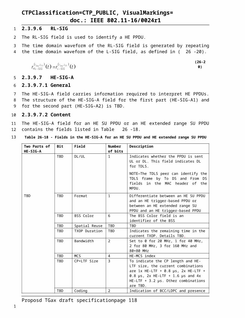
CTPClassification=CTP_PUBLIC, VisualMarkings=doc.: IEEE 802.11-16/0024r1
The sum of these over all streams is S=N SS . s.
Consecutive blocks of s bits are assigned to different spatial streams in a round robin fashion.
Let
(26-95)
For the NBlock . S bits of each OFDM symbol, S bits from the output of the encoder are divided among all spatial streams, s bits per stream.
Note that in all the different RU sizes, NCBPS=NBlock . S, therefore the coded bits of each OFDM symbol are always evenly allocated to Nss spatial streams.
The following equations are an equivalent description to the above procedure. Bit i at the output of the encoder is assigned to input bit k of spatial stream iSS where
where
26.3.10.5 Segment parserFor a 160 MHz and 80+80 MHz HE SU PPDU, a 160 MHz and 80+80 MHz HE MU PPDU, and a HE trigger-based PPDU with the RU spanning the entire PPDU bandwidth, the output bits of each stream parser are segment parsed as specified in 22.3.10.7.
26.3.10.6 BCC interleaversThere is some duplication here. I think we need to delete the Table 25-24 and its reference sentence.
The BCC interleaver parameters are defined in Table 26-27.Table 26-27 - BCC interleaver and LDPC tone mapper parameters
RU size (tones) BCC LDPCNcol Nrot DTM
26 8 2 152 16 11 3106 17 29 6242 26 58 9484 - - 12996 - - 20
For ease of explanation, the operation of the interleaver is described only for the SU case. For user u in the r-th RU of an MU transmission, the interleaver operates in the same way on the output bits for the user from the stream parser by replacing NSS, NCBPSS, NCBPSSI, and NBPSCS with NSS,r,u, NCBPSS,r,u, NCBPSSI,r,u, and NBPSCS,r,u, respectively. That is, the operation of the interleaver is the same as if the transmission were an SU one, consisting of bits from only that user.
The BCC interleaver operation is specified in 22.3.10.8 (BCC interleaver). The values of the interleaver parameters, NCOL, NROW, and NROT are selected based on the RU size of the user, and are given in Table 26-28.
Proposd TGax draft specification page 118
1
2
3
45
67
89
10
11
1213
141516
17
18
19
20
2122232425
262728
1
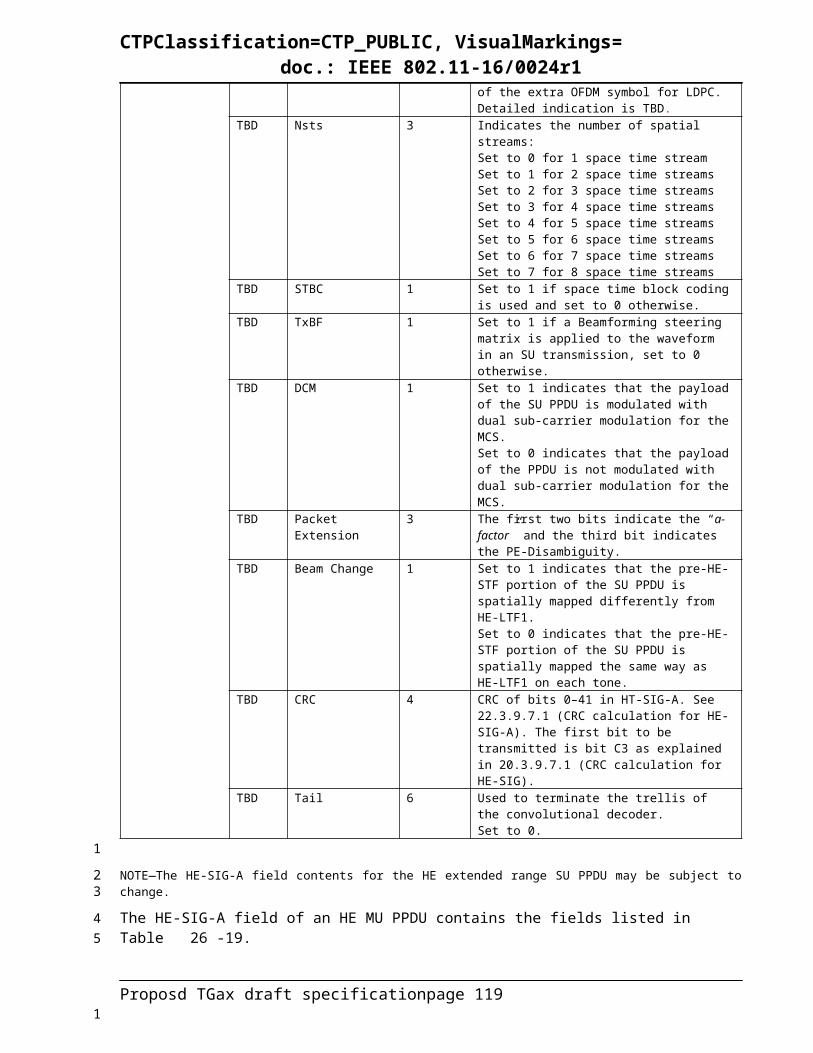
CTPClassification=CTP_PUBLIC, VisualMarkings=doc.: IEEE 802.11-16/0024r1Table 26-28 - BCC interleaver parameters
ParameterRU Size (tones)
26 52 106 242
NCOL 8 16 17 26
NROW 3 × NBPSCS 3 × NBPSCS 6 × NBPSCS 9 × NBPSCS
NROT (NSS ≤ 4) 2 11 29 58
26.3.10.7 Constellation mappingThe mapping between the input bits of the constellation mapper and complex constellation points for BPSK, QPSK, 16-QAM, 64-QAM and 256-QAM is as defined in 22.3.10.9 (constellation mapping).
1024-QAM is used as an optional feature for SU and MU using resource units equal to or larger than 242 tones in 11ax. For 1024-QAM, the constellation mapping is TBD.
Dual sub-carrier modulation (DCM) is an optional modulation scheme for the HE-SIG-B and Data fields. DCM is only applied to BPSK, QPSK and 16-QAM modulations.
When DCM is employed, bit sequences are mapped to a pair symbols where is in the range
of and is in the range of in order to exploit frequency
diversity. To maximize the frequency diversity, the indices of a pair of DCM subcarriers is
.
For QPSK modulation with DCM, the input stream is broken into groups of NCBPS or NCBPS,ru bits
. Each pair of bits is QPSK modulated to a symbol . This generates the constellation points for the lower half the data subcarriers in the RU. For the upper half of the data
sub-carriers in the RU, .
For BPSK and 16-QAM modulation with DCM, the constellation mapping is TBD.
26.3.10.8 Space-time block codingThis subclause defines a set of optional robust transmission techniques that are applicable only when using STBC coding. For an HE PPDU, STBC is allowed only with single spatial stream and two space-time streams, and its application is as indicated by the STBC bit in HE-SIG-A (TBD: undecided whether in HE-SIG-A for HE_MU). In an HE MU PPDU, STBC coding is used in all RUs or not used in any of the RUs. If in an RU, DL MU-MIMO is applied, STBC shall not be used in any RU in the HE MU PPDU.
The STBC encoding process is as described in clause 22.3.10.9.4 (Space-time block coding), with N SS , 0=1 and NSTS ,0=2.
26.3.10.9 LDPC tone mapperThe LDPC tone mapper parameters are defined in Table 26-27.
The LDPC tone mapping shall be performed on all LDPC encoded streams mapped in a RU as described in this subclause. LDPC tone mapping shall not be performed on streams that are encoded using BCC.
Proposd TGax draft specification page 119
1
2
3
45
67
89
10
11
12
13
14
1516
17
18
19
202122232425
2627
28
29
3031
1
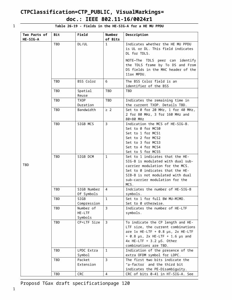
CTPClassification=CTP_PUBLIC, VisualMarkings=doc.: IEEE 802.11-16/0024r1
When DCM is applied to LDPC encoded streams, DTM_DCM shall be applied on both the lower half data subcarriers in a RU and the upper half data subcarriers of the RU. The LDPC tone-mapping distance parameter DTM and DTM_DCM are constant for each RU size and the values for different RU sizes are given in Table 26-29.
Table 26-29 – LDPC tone mapping distance for each RU size
ParameterRU Size (tones)
26 52 106 242 484 996 2x996
DTM 1 3 6 9 12 20 20
DTM_DCM 1 1 3 9 9 14 20
For an HE PPDU without DCM, the LDPC tone mapping for the LDPC encoded stream for user u in the r-th RU is done by permuting the stream of complex numbers generated by the constellation mappers (see 26.3.10.7) to
(26-96)
where NSD is the number of data tones in the r-th RU.
(26-97)
For a HE PPDU with DCM, the LDPC tone mapping for the LDPC encoded stream corresponding to user u in the r-th RU is done by permuting the stream of complex numbers generated by the constellation mappers (see 25.3.10.7) to
(26-98)
where
Proposd TGax draft specification page 120
1234
5
6
789
10
111213
14
1

CTPClassification=CTP_PUBLIC, VisualMarkings=doc.: IEEE 802.11-16/0024r1
NSD is the number of data tones in the r-th RU and
(26-99)
DTM_DCM is the LDPC tone mapping distance for the r-th RU when DCM is applied.NOTE—LDPC tone mapper for a 26-, 52-, 106-, 242-, 484- and 996-tone RU is defined as one segement. LDPC tone mapping is performed separately for the upper and lower 80 MHz frequency segments of a 2x996-tone RU as indicated by the frequency subblock index l in Error! Reference source not found. and Error! Reference source not found.
Since LDPC tone apping is not performed on BCC-coded streams, for BCC-coded streams, the following applies:
(26-100)
26.3.10.10 Segment deparserIn a transmission over a RU of 26, 52, 106, 242, 484 and 996 subcarriers, the segment deparsing is not performed (see Equation (22-90)).
For a 160 MHz HE SU PPDU, or a 160 MHz HE MU PPDU or HE trigger-based PPDU with the RU spanning the entire PPDU bandwidth, the two frequency subblocks at the output of the LDPC tone mapper are combined into one frequency segment as specified in Equation (22-89).
In an 80+80 MHz HE PPDU transmission, the segment deparsing is not performed (see Equation (22-91)).
Proposd TGax draft specification page 121
12
3
456
78
9
1011
121314
1516
1
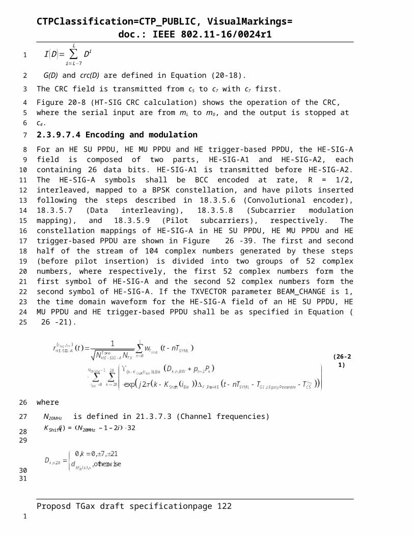
CTPClassification=CTP_PUBLIC, VisualMarkings=doc.: IEEE 802.11-16/0024r1
26.3.10.11 Pilot subcarriersFor a user transmitting on the i-th 26-tone RU in a given PPDU BW, two pilot tones shall be inserted in subcarriers k∈K R26i
, where K R 26i is given by i-th pilot index set in the row of given PPDU BW of Table
26-30.Table 26-30 - Pilot indices for 26-tone RU transmission
PPDU BW K R 26i
20 MHz, i=1:9 -116/-102, -90/-76, -62/-48, -36/-22, -10/10, 22/36, 48/62, 76/90, 102/116 40 MHz, i=1:18 -238/-224, -212/-198, -184/-170, -158/-144, -130/-116, -104/-90, -78/-64, -50/-36, -24/-10, 10/24,
36/50, 64/78, 90/104, 116/130, 144/158, 170/184, 198/212, 224/238 80 MHz, i=1:37 -494/-480, -468/-454, -440/-426, -414/-400, -386/-372, -360/-346, -334/-320, -306/-292, -280/-266,
-252/-238, -226/-212, -198/-184, -172/-158, -144/-130, -118/-104, -92/-78, -64/-50, -38/-24, -10/10, 24/38, 50/64, 78/92, 104/118, 130/144, 158/172, 184/198, 212/226, 238/252, 266/280, 292/306, 320/334, 346/360, 372/386, 400/414, 426/440, 454/468, 480/494
160 MHz, i=1:74 {pilot tone indices in 80 MHz -512, pilot tone indices in 80 MHz +512}
The pilot mapping Pnk for subcarrier k for symbol n shall be as specified in Equation (26-101).
Pn
KR26 i=¿¿¿¿
¿ (26-101)
where
Ψ i ,m is TBD for Pilot values for i-th 26-tone RU in a given PPDU BW.
For a user transmitting on the i-th 52-tone RU in a given PPDU BW, four pilot tones shall be inserted in subcarriers k∈K R52i
, where K R 52i is given by i-th pilot index set in the row of given PPDU BW of Table
26-31.Table 26-31 - Pilot indices for 52-tone RU transmission
PPDU BW K R 52i
20 MHz, i=1:4 -116/-102/-90/-76, -62/-48/-36/-22, 22/36/48/62, 76/90/102/11640 MHz, i=1:8 -238/-224/-212/-198, -184/-170/-158/-144, -104/-90/-78/-64, -50/-36/-24/-10, 10/24/36/50,
64/78/90/104, 144/158/170/184, 198/212/224/238 80 MHz, i=1:16 -494/-480/-468/-454, -440/-426/-414/-400, -360/-346/-334/-320, -306/-292/-280/-266, -252/-238/-
226/-212, -198/-184/-172/-158, -118/-104/-92/-78, -64/-50/-38/-24, 24/38/50/64, 78/92/104/118, 158/172/184/198, 212/226/238/252, 266/280/292/306, 320/334/346/360, 400/414/426/440, 454/468/480/494
160 MHz, i=1:32 {pilot tone indices in 80 MHz -512, pilot tone indices in 80 MHz +512}
The pilot mapping Pnk for subcarrier k for symbol n shall be as specified in Equation (26-102).
Pn
KR52i =¿¿¿¿
¿ (26-102)
where
Ψ i ,m is TBD for Pilot values for i-th 52-tone RU in a given PPDU BW.
For a user transmitting on the i-th 106-tone RU in a given PPDU BW, four pilot tones shall be inserted in subcarriers k∈K R 106 i
, where K R 106i is given by i-th pilot index set in the row of given PPDU BW of
Table 26-32.
Proposd TGax draft specification page 122
1
234
5
6
7
8
91011
12
13
14
15
161718
1

CTPClassification=CTP_PUBLIC, VisualMarkings=doc.: IEEE 802.11-16/0024r1
Table 26-32 - Pilot indices for 106-tone RU transmission
PPDU BW K R 106i
20 MHz, i=1:2 -116/-90/-48/-22, 22/48/90/11640 MHz, i=1:4 -238/-212/-170/-144, -104/-78/-36/-10, 10/36/78/104, 144/170/212/238 80 MHz, i=1:8 -494/-468/-426/-400, -360/-334/-292/-266, -252/-226/-184/-158, -118/-92/-50/-24, 24/50/92/118,
158/184/226/252, 266/292/334/360, 400/426/468/494160 MHz, i=1:16 {pilot tone indices in 80MHz -512, pilot tone indices in 80MHz +512}
The pilot mapping Pnk for subcarrier k for symbol n shall be as specified in Equation (26-103).
Pn
KR106 i=¿¿¿¿
¿ (26-103)
where
Ψ i , m is TBD for Pilot values for i-th 106-tone RU in a given PPDU BW.
For a user transmitting on the i-th 242-tone RU in a given PPDU BW, eight pilot tones shall be inserted in subcarriers k∈K R 242 i
, where K R 242i is given by i-th pilot index set in the row of given PPDU BW of
Table 26-33.Table 26-33 - Pilot indices for 242-tone RU transmission
PPDU BW K R 242i
20 MHz, i=1 -116/-90/-48/-22/22/48/90/11640 MHz, i=1:2 -238/-212/-170/-144/-104/-78/-36/-10, 10/36/78/104/144/170/212/23880 MHz, i=1:4 -494/-468/-426/-400/-360/-334/-292/-266,-252/-226/-184/-158/-118/-92/-50/-24,
24/50/92/118/158/184/226/252, 266/292/334/360/ 400/426/468/494160 MHz, i=1:8 {pilot tone indices in 80 MHz -512, pilot tone indices in 80 MHz +512}
The pilot mapping Pnk for subcarrier k for symbol n shall be as specified in Equation (26-104).
Pn
KR242i =¿¿¿¿
¿ (26-104)
where
Ψ i , m is TBD for Pilot values for i-th 242-tone RU in a given PPDU BW.
For a user transmitting on the i-th 484-tone RU in a given PPDU BW, sixteen pilot tones shall be inserted in subcarriers k∈K R484 i
, where K R 484 i is given by i-th pilot index set in the row of given PPDU BW of
Table 26-34.Table 26-34 - Pilot indices for 484-tone RU transmission
PPDU BW K R 484 i
20 MHz N/A40 MHz, i=1 -238/-212/-170/-144/-104/-78/-36/-10/10/36/78/104/144/170/212/23880 MHz, i=1:2 -494/-468/-426/-400/-360/-334/-292/-266/-252/-226/-184/-158/-118/-92/-50/-24,
24/50/92/118/158/184/226/252/266/292/334/360/400/426/468/494160 MHz, i=1:4 {pilot tone indices in 80 MHz -512, pilot tone indices in 80 MHz +512}
The pilot mapping Pnk for subcarrier k for symbol n shall be as specified in Equation (26-105).
Proposd TGax draft specification page 123
1
2
3
4
567
8
9
10
11
121314
15
16
1
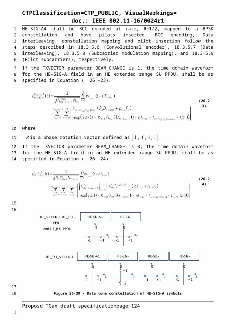
CTPClassification=CTP_PUBLIC, VisualMarkings=doc.: IEEE 802.11-16/0024r1
Pn
KR484 i=¿¿¿¿
¿ (26-105)
where
Ψ i ,m is TBD for Pilot values for i-th 484-tone RU in a given PPDU BW.
For a user transmitting on the i-th 996-tone RU in a given PPDU BW, sixteen pilot tones shall be inserted in subcarriers k∈K R996 i
, where K R 996i is given by i-th pilot index set in the row of given PPDU BW of
Table 26-35.Table 26-35 - Pilot indices for 996-tone RU transmission
PPDU BW K R 996i
20 MHz N/A40 MHz N/A80 MHz, i=1 -468/-400/-334/-266/-226/-158/-92/-24/24/92/158/226/266/334/400/468160 MHz, i=1:2 {pilot tone indices in 80 MHz -512, pilot tone indices in 80 MHz +512}:
-980/-912/-846/-778/-738/-670/-604/-536/-488/-420/-354/-286/-246/-178/-112/-44, 44/112/178/246/286/354/420/488/536/604/670/738/778/846/912/980
The pilot mapping Pnk for subcarrier k for symbol n shall be as specified in Equation (26-106).
Pn
KR996 i=¿¿¿¿
¿(26-10
6)
where
Ψ i ,m is TBD for Pilot values for 996-tone RU in 80 MHz PPDU BW.
For a 160 MHz transmission, the 80 MHz pilot mapping is replicated in the two 80 MHz subchannels
of the 160 MHz transmission. Specifically, thirty-two pilot tones shall be inserted in subcarriers k ∈K R2x996
, where K R 2×996 is given by {-980, -912, -846, -778, -738, -670, -604, -536, -488, -420, -354, -286, -246, -178, -112, -44, 44, 112, 178, 246, 286, 354, 420, 488, 536, 604, 670, 738, 778, 846, 912, 980}. The pilot mapping Pn
k for subcarrier k for symbol n shall be as specified in Equation (26-107) .
Pn
KR2x996={Ψ i , nmod 8¿,Ψ i ,(n+1) mod 8 ,Ψ i ,(n+2 )mod 8 , Ψ i ,(n+3) mod 8 ,Ψ i , (n+4 )mod 8 ,Ψ i ,(n+5 )mod 8,Ψ i ,(n +6 )mod8 ,Ψ i ,(n+7 )mod 8 ,. ..¿ ¿Ψ i ,(n+8)mod 8 ,Ψ i,(n+9 )mod 8 ,Ψ i ,(n+10 )mod 8 ,Ψ i ,(n+11)mod 8 ,Ψ i ,(n+12 )mod 8, Ψ i ,(n+13 )mod8 ,Ψ i ,(n+14 )mod 8 ,Ψ i ,(n+15 )mod 8 ,. .. ¿Ψ i ,n mod 8 ,Ψ i, (n+1 )mod 8 , Ψ i, (n+2)mod 8 ,Ψ i ,(n+3 )mod 8, Ψ i, (n+ 4)mod8 ,Ψ i ,(n+5)mod 8 ,Ψ i ,(n+6)mod 8 ,Ψ i, (n+7 )mod 8 , .. .¿Ψ i ,(n+8)mod 8 ,Ψ i, (n+9 )mod 8 ,Ψ i ,(n+10 )mod 8 ,Ψ i ,(n+11)mod 8 ,Ψ i ,(n+12 )mod 8 , Ψ i ,(n+13)mod8 ,Ψ i,(n+14 )mod 8 ,Ψ i ,(n+15 )mod 8}¿Pn
k∉K R2x996 =0 ¿ (26-107)
where
Ψ i ,m is TBD for Pilot values for 996-tone RU in 80 MHz PPDU BW.
Proposd TGax draft specification page 124
1
2
345
6
7
8
9
10
11121314
15
16
1
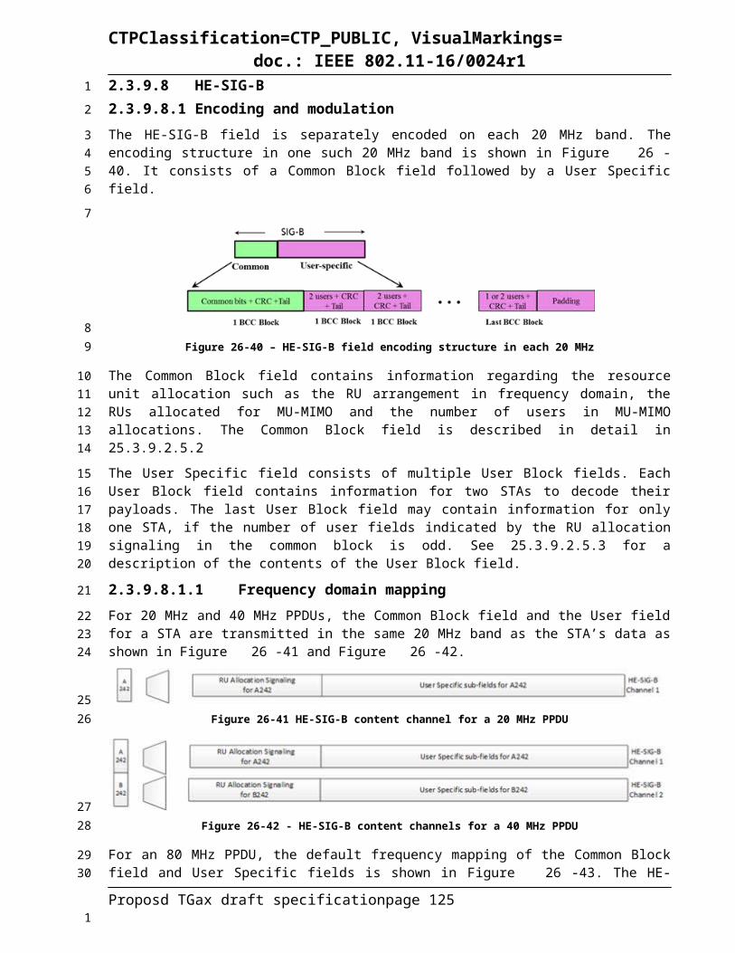
CTPClassification=CTP_PUBLIC, VisualMarkings=doc.: IEEE 802.11-16/0024r1
For a noncontiguous 80+80 MHz transmission, each frequency segment shall follow the 80 MHz pilot tone allocation and values defined for 996-tone RU in 80 MHz transmission as specified in Equation (26-106) and TBD Pilot values for 996-tone RU in 80 MHz PPDU BW.
The above pilot mapping shall be copied to all space-time streams before the space-time stream cyclic shifts are applied.
26.3.10.12 OFDM ModulationThe time domain waveform of the Data field of an HE PPDU that is not an HE trigger-based PPDU, from transmit chain iTX, 1 iTX NTX , shall be as defined in Equation (26-108).
(26-108)
where
pn is defined in 18.3.5.10 (OFDM modulation)Pn
kis defined in Error: Reference source not found
is the transmitted constellation for user u in the r-th RU at subcarrier k, space-time stream m, and Data field OFDM symbol n and is defined in Error: Reference source not found.
has the value given in Error: Reference source not found
is given in 26.3.9.2 (Cyclic shift for Pre-HE modulated fields)TGI Data is the guard interval duration as defined in Table 25-xxx (Timing related constants) of 25.3.6
(Timing related parameters).
(26-109)
where
KPilot is the set of subcarrier indices of pilot tones, as defined in 25.3.7.3 (Pilot tones).
is defined in Equation (26-110).
(26-110)
where
Kr,min is the minimum value of the set Kr;
is the cardinality of a set Ф.NOTE – Mr(k) translates a subcarrier index k (−NSR ≤ k ≤ NSR) into the index of data symbols in a transmission over a RU (0 ≤ Mr(k) ≤ NSD,r). The subcarrier index k for the data tone is first offset by the minimum value of subcarrier index Kr,min (for the lower edge tone) in this RU, and then subtracted by the number of pilot tones falling in between the data tone and the edge tone.
Proposd TGax draft specification page 125
123
45
6
78
9
10
11
1213
14
15
1617
18
19
20
21
22
23
242526
1
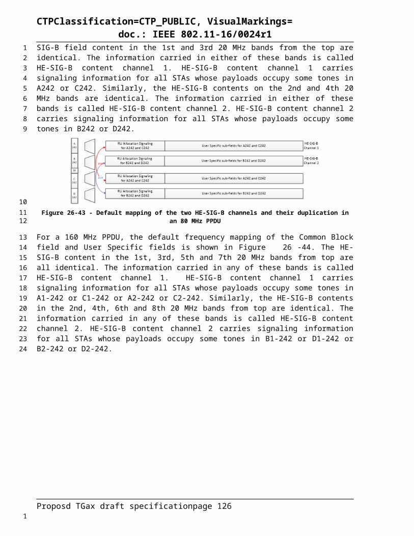
CTPClassification=CTP_PUBLIC, VisualMarkings=doc.: IEEE 802.11-16/0024r1
In a noncontiguous 80+80 MHz transmission, each frequency segment shall follow the 80 MHz HE subcarrier mapping as specified in 26.3.7 (OFDMA and SU tone allocation).
The time domain waveform of the Data field of an HE trigger-based PPDU for user u in the r-th RU from transmit chain iTX, 1 iTX NTX shall be as defined in Equation (26-111).
(26-111)
where
is a spatial mapping/steering matrix with NTX rows and NSTS,r,total columns for subcarrier k in freque
ncy segment iSeg. may be frequency dependent, and the dimension may be variant in each RU. Refer to the descriptions in 22.3.10.11.1 (Transmission in VHT format) for examples of .
26.3.10.13 Dual carrier modulationDual sub-carrier modulation (DCM) modulates the same information on a pair of sub-carriers. DCM is an optional modulation scheme for the HE-SIG-B and Data fields. DCM is only applied to BPSK, QPSK and 16-QAM modulations.
The constellation mapper for DCM is defined in 25.3.10.6. The DCM tone mapper is TBD.
26.3.10.14 Packet extensionA HE PPDU may have a Packet Extension (PE) field appended at the end of the PPDU, with possible durations being 0 µs, 4 µs, 8 µs, 12 µs, or 16 µs. The PE field, when present, shall be transmitted with the same average power as the Data field, and its content is arbitrary (PE content TBD).
The PE field is applied for the recipient of the PPDU to obtain longer processing time at the end of a HE PPDU, and its duration is determined by both the a-factor value in the last OFDM symbol(s) of the Data field, and the maximum PE duration requested by the recipient for the signal bandwidth (or RU size), the number of spatial streams, and the constellation size of the current PPDU, which is based on the Maximum PE capabilities as defined in HE capabilities field (8.4.2.1 (HE Capabilities Element)).
For a HE PPDU, the maximum PE durations as defined by the Maximum PE capabilities in HE capabilities (8.4.2.1 (HE Capabilities Element)) are 0 µs, 8 µs and 16 µs.
— A 0 µs maximum PE duration means no PE is present.
— A 8 µs maximum PE duration means that a PE field of 0 µs, 0 µs, 4 µs, and 8 µs are appended at the end of the PPDU, corresponding to a-factor being 1, 2, 3 and 4, respectively, as shown in Figure 25.3.10.9-1 (PE field when maximum PE duration is 8 µs (non STBC)).
— A 16 µs maximum PE duration means that a PE field of 4 µs, 8 µs, 12 µs, and 16 µs are appended at the end of the PPDU, corresponding to a-factor being 1, 2, 3 and 4, respectively, as shown in Figure 25.3.10.9-2 (PE field when maximum PE duration is 16 µs (non STBC)).
Proposd TGax draft specification page 126
12
34
5
6
78
910
111213
14
15
161718
1920212223
2425
26
272829
303132
1

CTPClassification=CTP_PUBLIC, VisualMarkings=doc.: IEEE 802.11-16/0024r1
FEC output bits Post FEC Padding bits
a = 1
OFDM modulation
Symbol NSYM
FEC output bits Post FEC Padding bits
a = 2
OFDM modulation
Symbol NSYM
FEC output bits Post FEC Padding bits
a = 3
OFDM modulation
Symbol NSYM
FEC output bits
a = 4
OFDM modulation
Symbol NSYM
PE
PE
4 us
8 us
Data Field
Data Field
Data Field
Data Field
Figure 26-51 - PE field when maximum PE duration is 8 µs (non STBC)
FEC output bits Post FEC Padding bits
a = 1
OFDM modulation
Symbol NSYM
FEC output bits Post FEC Padding bits
a = 2
OFDM modulation
Symbol NSYM
FEC output bits Post FEC Padding bits
a = 3
OFDM modulation
Symbol NSYM
FEC output bits
a = 4
OFDM modulation
Symbol NSYM
PE
PE
4 us
8 us
Data Field
Data Field
Data Field
Data Field
PE
12 us
PE
16 us
Figure 26-52 - PE field when maximum PE duration is 16 µs (non STBC)
For an HE MU PPDU, the AP computes the PE duration, T PE , u, for each user u, according to the common a-factor value among all users as described in 26.3.10.3.4, the Maximum PE Duration capabilities, the RU size, the number of spatial streams and constellation size for user u. The AP shall choose the largest PE duration among all the users as the common PE duration of the current HE MU PPDU as:
(26-112)
and then append the PE field at the end of the current HE MU PPDU, with duration T PE.
For an HE trigger-based PPDU, the AP indicates the common PE duration, T PE, for all the users in the Trigger frame. Each user, when responding the Trigger frame with an HE trigger-based PPDU, shall
Proposd TGax draft specification page 127
12
34
5678
9
1011
1
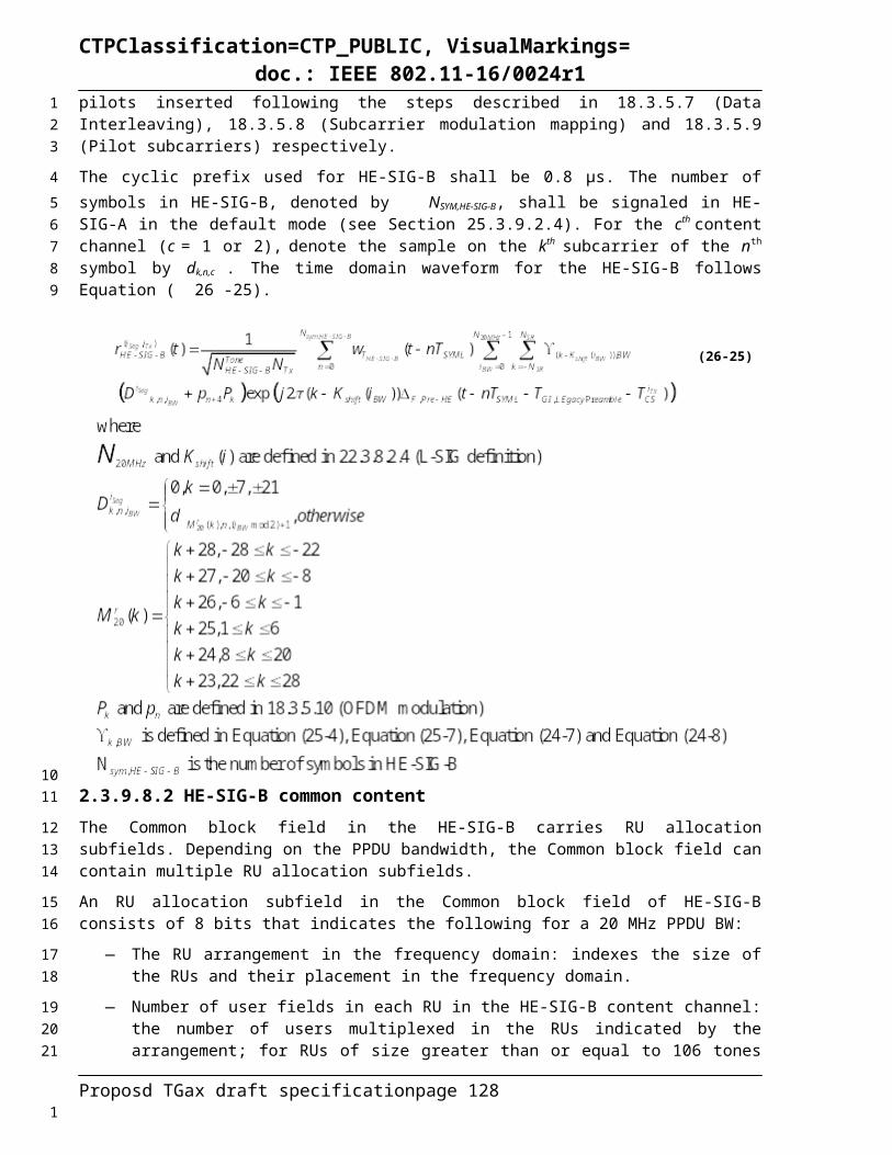
CTPClassification=CTP_PUBLIC, VisualMarkings=doc.: IEEE 802.11-16/0024r1
append PE field at the end of the current HE trigger-based PPDU, with a duration T PE. The value of TPE is TBD.
Should the HE-SIG-A bits definition below be moved into 25.3.9.2.4 (HE-SIG-A)?
The 3-bit Packet Extension field in HE-SIG-A are defined as in Table 26-36.Table 26-36 - Packet Extension field in HE-SIG-A
Name bits Definitiona-factor b0-b1 Indicates a-factor value of current PPDUPE Disambiguity b2 Indicates PE disambiguity
The a-factor subfield of the Packet Extension field is encoded as shown in Table 26-37.Table 26-37 - a-factor subfield encoding
a-factor value a-factor subfield encoding1 b012 b103 b114 b00
The PE Disabmbituity subfield of the Packet Extension field shall be set to 1 if the condition in Equation (26-113) is met, otherwise it shall be set to 0.
(26-113)
where
T PE is the PE field duration
T SYM is the symbol duration of the Data field as defined in 26.3.6 (Timing related parameters)
TXTIME (in µs) is defined in 26.4.3.
Based on PE disambiguity field and a-factor field, the recipient shall compute NSYM and TPE listed in 26.3.15.
26.3.11 Non-HT Duplicate TransmissionWhen the TXVECTOR parameter FORMAT is NON_HT and the TXVECTOR parameter NON_HT_MODULATION is NON_HT_DUP_OFDM, the transmitted PPDU is a non-HT duplicate. Non-HT duplicate transmission is used to transmit to non-HT OFDM STAs, HT STAs, VHT STAs, HE STAs that may be present in a part of a 40 MHz, 80 MHz, or 160 MHz channel (see Error: Referencesource not found). The RL-SIG, HE-SIG-A, HE-SIG-B, HE-STF, and HE-LTF fields are not transmitted. The L-STF, L-LTF, and L-SIG fields shall be transmitted in the same way as in the HE transmission when the TXVECTOR parameter BEAM_CHANGE is 0, with the exceptions for the Rate and Length fields which shall follow 18.3.4 (SIGNAL field).
In a 40 MHz non-HT duplicate transmission, the Data field shall be as defined by Equation (20-61).
For 80 MHz and 160 MHz non-HT duplicate transmissions, the Data field shall be as defined by Error:Reference source not found.
In a noncontiguous 80+80 MHz non-HT duplicate transmission, data transmission in each frequency segment shall be as defined for an 80 MHz non-HT duplicate transmission in Error: Reference source notfound.
Proposd TGax draft specification page 128
12
3
4
5
6
7
8
910
11
12
13
14
1516
17
1819202122232425
26
2728
293031
1
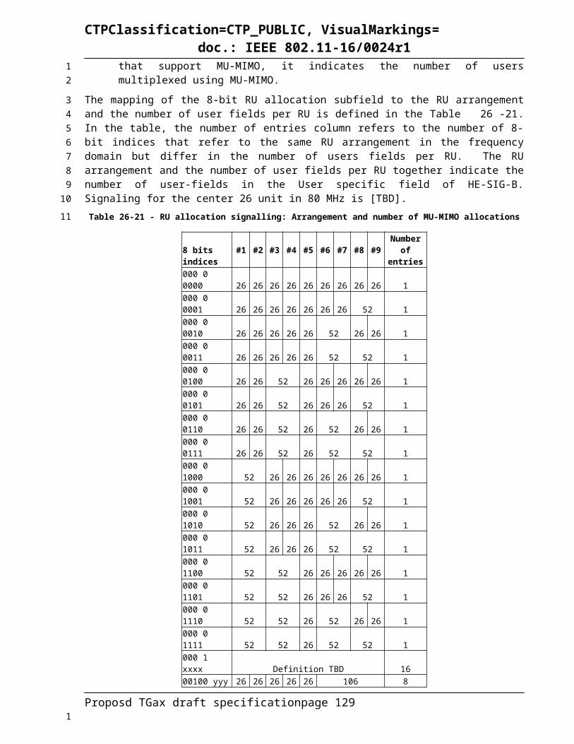
CTPClassification=CTP_PUBLIC, VisualMarkings=doc.: IEEE 802.11-16/0024r1
26.3.12 MU-MIMO26.3.12.1 IntroductionDL MU MIMO is specified in 22.3.11 for full band transmission. In this amendment, MU-MIMO is also applicable on a subset of active RUs within PPDU bandwidth in both DL and UL. The non-AP STAs in the same MU-MIMO group are allocated the same resource unit. The combination of SU-MIMO and MU-MIMO on different RU for different non-AP STA in one PPDU is supported.
26.3.12.2 Minimum RU size in MU MIMO transmissionBoth DL and UL MU MIMO shall transmit on the RU of at least 106 tones.
26.3.12.3 DL MU-MIMO26.3.12.3.1 IntroductionFor DL MU-MIMO beamforming in RU r, the receive signal vector in subcarrier k (where subcarrier k is one of the subcarriers in RU r, k∈K r) at beamformee u, yk , u=[ yk , 0 , yk , 1 ,⋯ , y k ,N R Xu
−1 ]T , is shown in
Equation (26-114), where xk=[xk , 0T , xk ,1
T ,⋯ , xk , Nuser ,r−1T ]T denotes the transmit signal vector in subcarrier
k for all Nuser beamformees, with xk ,u=[ xk ,0 , xk , 1,⋯ , xk , N STS, r ,u−1 ]T being the transmit signal for beamformee u.
yk , u=H k ,u × [Q k ,0 ,Q k ,1 ,⋯ , Qk , Nuser−1 ] × xk+n (26-114)
where
Hk,u is the channel matrix from the beamformer to beamformee u in subcarrier k with dimensions N R Xu
× NTX
N R Xuis the number of receive antennas at beamformee u
Qk , u is a steering matrix for beamformee u in subcarrier k with dimensions NTX × NSTS ,r ,u
Nuser,r is the number of HE MU PPDU recipients in RU r (see Table 26-9)
n is a vector of additive noise and may include interference
The DL MU-MIMO steering matrix Qk= [Qk ,0 , Qk ,1 ,⋯ , Qk , Nuser ,r−1 ] can be determined by the beamformer using the beamforming feedback for subcarrier k from beamformee u, where u=0,1 ,⋯ , Nuser ,r−1. The feedback report format is TBD. The steering matrix that is computed (or updated) using new beamforming feedback from some or all of participating beamformees might replace the existing steering matrix Qk for the next DL MU-MIMO data transmission. The beamformee group for the DL MU transmission is signaled in HE-SIG-B (see 26.3.9.8.3 and 26.3.12.3.4).
26.3.12.3.2 Beamforming feedbackTBD
26.3.12.3.3 Maximum number of total spatial streams in a VHT MU PPDUA DL MU-MIMO capable STA shall support reception of DL MU PPDUs with the total number of space-time streams across the N_user users being less than or equal to its DL MU-MIMO STS Capability in the HE Capabilities.
Proposd TGax draft specification page 129
1
2
3456
7
8
9
10
11
12
13
14
15
16
17
1819
20
21
22
2324
252627282930
31
32
33
343536
1

CTPClassification=CTP_PUBLIC, VisualMarkings=doc.: IEEE 802.11-16/0024r1
26.3.12.3.4 Resource indication and STA self identificationAP shall transmit HE MU PPDU. The UL/DL field in the HE-SIG-A shall be set TBD (for DL). If the value of SIGB Compression field in HE-SIG-A is 0, the RU allocation signaling in the HE-SIG-B common field indicates the combination of RUs in current PPDU bandwidth and the number of STAs on each RU for SU/MU MIMO transmission. The number of users in RU r for MU-MIMO transmission, Nuser,r is indicated together with the RU allocation as defined in Table 26-21. If the value of SIGB Compression field in HE-SIG-A is 1, there is no RU allocation signaling in HE-SIG-B common field. The number of STAs in the MU MIMO group is indicated in the TBD field in HE-SIG-A. the number of spatial streams Nss,r,u is indicated by NSTS field in user specific block as defined in Table 26-22 and Table26-23.The allocated spatial streams for a designated MU MIMO user and the total number of spatial streams on the RU are indicated in spatial configuration field of user specific block containing the STA ID of designated MU MIMO STA as defined in Table 26-24.
When processing the HE-SIG-B, a STA will look at information of each RU to find out its Membership Status, i.e., if it belongs to a beamformee group in a certain RU. If Nuser,r STAs are scheduled in RU r, there are Nuser,r user specific blocks for RU r. Each user specific block has an 11-bit field indicating the STA ID. A STA identifies itself as a member in the beamformee group in the RU, if its STA ID matches one of the STA IDs. The user position is indicated by the block index. From a multiplexing information lookup table for Nuser,r, the ordered number of spatial streams for all members in the beamformee group in RU r, Nss,r,u, u=1,…, Nusers,u, could be obtained. The spatial streams of different users are ordered in accordance to user position values, i.e., the spatial streams for the user in user position 0 come first, followed by the spatial streams for the user in position 1, followed by the spatial streams for the user in position 2, and followed by the spatial streams for the user in position 3, and so on.
A STA is also able to identify the space-time streams intended for other STAs that act as interference. HE-LTF symbols in the HE DL MU PPDU are used to measure the channel for the space-time streams intended for the STA and can also be used to measure the channel for the interfering space-time streams. To successfully demodulate the space-time streams intended for the STA, it is recommended that the STA uses the channel knowledge for all space-time streams to reduce the effect of interfering space-time streams.
If a STA finds that it is a member of the beamformee group in RU r, its corresponding NSTS,r,u interpreted from the HE-SIG-B user specific blocks shall not be zero for the STA in the PPDU. If a STA finds that it is not a member of the beamformee group in RU r, then the STA may elect not to process RU r in the remainder of the PPDU.
26.3.12.4 UL MU-MIMO26.3.12.4.1 IntroductionUL MU-MIMO is a technique to allow multiple STAs to transmit simultaneously over the same frequency resource to the receiver. The concept is very similar to SU-MIMO where multiple space-time streams are transmitted simultaneously over the same frequency resource utilizing spatial multiplexing through multiple antennas at the transmitter and receiver. The key difference from SU-MIMO is that in UL MU-MIMO, the transmitted streams originate at multiple transmitters.
For UL MU-MIMO transmissions, support for both single stream pilots and the masking the LTF sequence of each spatial stream by a distinct orthogonal code is mandatory at the transmitter side (non-AP STA).
26.3.12.4.2 Resource Indication and STA Self IdentificationUL MU-MIMO transmissions are preceded by a Trigger frame from the AP. Similar as UL OFDMA cases, the Trigger frame indicates the transmitting STAs in the common part about when to transmit the UL MU-MIMO PPDUs, the duration of the payload, and packet-extension. The CP length for UL OFDMA/MU-MIMO transmissions shall also be explicitly indicated by AP in the Trigger frame. The value of CP length for all users addressed by the Trigger frame shall be the same. The Trigger frame shall use 1 bit to indicate whether the UL MU-MIMO transmission following it uses single stream pilots or a
Proposd TGax draft specification page 130
1
23456789
101112
13141516171819202122
232425262728
29303132
33
34
3536373839
404142
43
444546474849
1
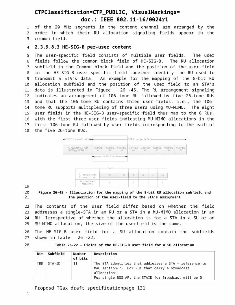
CTPClassification=CTP_PUBLIC, VisualMarkings=doc.: IEEE 802.11-16/0024r1
mask on each spatial stream of the LTF sequence by a distinct orthogonal code. When single stream pilot is used, no masking is applied to the HE LTF. The allocated RU and spatial streams are carried in the fields of RU allocation info and SS allocation of Per User Info field, where Address field is set as the AID of designated MU MIMO STA. Details TBD.
If a STA finds that there is no Per User Info field in Trigger frame carrying the STA’s AID in the Address field, then the STA will not transmit in the following HE trigger-based PPDU.
26.3.12.4.3 Pre-corrections in UL MU-MIMOSince multiple transmitters take part in an UL MU-MIMO transmission, it requires time, frequency, sampling clock and power pre-correction by the participating STAs to mitigate the synchronization related issues at the AP. Frequency and sampling clock pre-corrections are needed to prevent inter-carrier interference. Power pre-correction is done through power control described in Error: Reference source notfound. The Trigger frame serves as a reference DL frame for the STAs to do the aforementioned pre-corrections to the UL PPDUs. The accuracy requirements on these pre-corrections are specified in section x.x.x.
26.3.12.4.4 Power control in UL MU-MIMOTBD
26.3.12.4.5 Maximum number of spatial streams in UL MU-MIMO PPDUsAn UL MU-MIMO capable STA shall support transmission of UL MU PPDUs with the number of space-time streams being less than or equal to its UL MU-MIMO STS Capability in HE Capabilities.
26.3.12.4.6 Requirements for STAs transmitting HE trigger-based PPDUsA STA that transmits an HE trigger-based PPDU shall support per chain max(P-32, -10 dBm) as the minimum transmit power, with P the maximum power the STA can transmit at the antenna connector of that chain using MCS0 while meeting the TX EVM and spectral mask requirements. A STA transmitting at and above the minimum power shall support the EVM requirements for MCS7 (TBD whether support for higher MCS).
A STA that transmits an HE trigger-based PPDU shall support the absolute transmit power requirements and the RSSI measurement accuracy requirements defined in Table 26-38.
Table 26-38 - Transmit power and RSSI measurement accuracy
ParameterMinimum Requirement
CommentsClass A Class B
Absolute transmit power accuracy ±3 dB ±9 dB Accuracy of achieving a specified transmit
power
RSSI measurement accuracy
±2 dB ±5 dB
Difference between the actual RSSI and the measured RSSI
Requirements are valid from minimum Rx to maximum Rx input power
A STA that transmits an HE trigger-based PPDU shall pre-compensate for carrier frequency offset (CFO) error and timing drift. After compensation, the absolute value of residual CFO error with respect to the PPDU carrying the associated Trigger frame shall not exceed 350 Hz for data subcarriers when measured as the 10% point of CCDF of CFO errors in AWGN at a received power of -60 dBm in the primary 20MHz. The residual CFO error measurement shall be made on the HE trigger-based PPDU following the HE-SIG-A field.
Proposd TGax draft specification page 131
1234
56
7
89
1011121314
15
16
17
1819
20
2122232425
2627
28
293031323334
1

CTPClassification=CTP_PUBLIC, VisualMarkings=doc.: IEEE 802.11-16/0024r1
A STA that transmits an HE trigger-based PPDU shall have timing accuracy of ±0.4 µs relative to the PPDU carrying the Trigger frame. This requirement does not include round trip delay.
26.3.13 Transmit specification26.3.13.1 Transmit spectral mask26.3.13.2 Spectral flatness26.3.13.3 Transmit center frequency and symbol clock frequency toleranceTransmit center frequency and the symbol clock frequency for all transmit antennas and frequency segments shall be derived from the same reference oscillator.
26.3.13.4 Modulation accuracy26.3.13.4.1 Introduction to modulation accuracy tests26.3.13.4.2 Transmit center frequency leakageThe TX LO leakage requirement for all transmission modes shall be the following. The power measured at the location of the RF LO using resolution BW 78.125 kHz shall not exceed the maximum of –32 dB relative to the total transmit power and −20 dBm, or equivalently max(P−32, −20), where P is the transmit power per antenna in dBm. The transmit center frequency leakage is specified per antenna.
26.3.13.4.3 Transmitter constellation error
26.3.14 HE transmit procedureTBD
26.3.15 HE receive procedureTBD
26.4 HE PLME
26.4.1 PLME_SAP sublayer management primitivesTable 25-1 (HE PHY MIB attributes (11ax)) lists the MIB attributes that may be accessed by the PHY entities and the intralayer of higher level LMEs. These attributes are accessed via the PLME-GET, PLME-SET, PLME-RESET, and PLME-CHARACTERISTICS primitives defined in 6.5 (PLME SAP interface).
26.4.2 PHY MIBTBD
26.4.3 TXTIME and PSDU_LENGTH calculationThe value of the TXTIME parameter returned by the PLME-TXTIME.confirm primitive shall be calculated for a HE PPDU using Equation (26-115) for an HE SU PPDU and HE trigger-based PPDU, Equation (26-116) for an HE MU PPDU and Equation (26-117) for an HE extended range SU PPDU.
(26-115)
(26-116)
Proposd TGax draft specification page 132
12
3
4
5
6
78
9
10
11
12131415
16
17
18
19
20
21
22
23242526
27
28
29
303132
1

CTPClassification=CTP_PUBLIC, VisualMarkings=doc.: IEEE 802.11-16/0024r1
(26-117)
where
, , , , , , , , , and
are defined in Table 26-6 (Timing-related constants)
and are defined in Table 26-9 (Frequently used parameters)
For an HE NDP PPDU, there is no Data field and .
For an HE SU PPDU and HE extended range SU PPDU using BCC encoding, the total number of OFDM symbols in the Data field is given by Equation (26-118).
(26-118)
where
is equal to 2 when STBC is used, and 1 otherwise.
For an HE SU PPDU and HE extended range SU PPDU using LDPC encoding, the total number of OFDM symbols in the Data field, NSYM, is given in 26.3.10.3.2 (LDPC coding).
For an HE MU PPDU (including both MU-MIMO and OFDMA), the total number of OFDM symbols in the Data field, NSYM, is given in 26.3.10.3.4 (Encoding process for an HE MU PPDU).
For an HE trigger-based PPDU, the total number of OFDM symbols in the Data field, NSYM, is given in 26.3.10.3.5 (Encoding process for an HE trigger-based PPDU).
is given by Equation (26-112).
The value of the PSDU_LENGTH parameter returned in the PLME-TXTIME.confirm primitive for an HE SU PPDU and HE extended range SU PPDU is calculated using Equation (26-119).
(26-119)
where
is given by Equation (26-68) for BCC encoding and by Equation (26-73) for LDPC encoding;
is 2 when STBC is used, and 1 otherwise;
is given in 26.5 (Parameters for HE-MCSs);
Proposd TGax draft specification page 133
1
2
3
4
5
6
7
89
10
11
12
1314
1516
1718
19
2021
22
23
24
25
1

CTPClassification=CTP_PUBLIC, VisualMarkings=doc.: IEEE 802.11-16/0024r1
is given by Equation (26-64)
The value of the PSDU_LENGTH parameter for user u returned in the PLME-TXTIME.confirm primitive and in the RXVECTOR for a HE MU PPDU is calculated using Equation (26-120).
(26-120)
where
is given by Equation (26-81)
is given by Equation (26-82)
The value of the PSDU_LENGTH parameter returned in the PLME-TXTIME.confirm primitive for an HE NDP PPDU is 0.
26.4.4 HE PHYThe static HE PHY characteristics, provided through the PLME-CHARACTERISTICS service primitive, shall be as shown in Table 20-25 (HT PHY characteristics) unless otherwise listed in Table 26-39. The definitions for these characteristics are given in 6.5 (PLME SAP interface).
Table 26-39 - HE PHY characteristics
Characteristics Value aTxPHYDelay Implementation dependent aRxPHYDelay Implementation dependent aCCAMidTime 25 µs aPPDUMaxTime 5.484 ms aPSDUMaxLength TBD
26.5 Parameters for HE-MCSsThe rate-dependent parameters for 26-tone RU, 52-tone RU, 106-tone RU, 242-tone RU and non-OFDMA 20 MHz, 484-tone RU and non-OFDMA 40 MHz, 996-tone RU and non-OFDMA 80 MHz, non-OFDMA 160 MHz and 80+80 MHz Nss = 1, …, 8 are given in Table 26-88 through Table 26-95. Support for HE-MCS 8, 9, 10, and 11 (when valid) is optional in all cases. HE-MCS 10 and 11 (1024-QAM) are applicable only to RU sizes equal to or larger than 242 tones.
Dual sub-carrier modulation (DCM) is an optional modulation scheme for any OFDMA and non OFDMA transmissions. DCM is only applicable to MCS 0, 1, 3 and 4 with up to TBD number of streams and for TBD RU sizes. A HE STA shall support single spatial stream HE-MCSs within the range HE-MCS 0 to HE-MCS 7 for all channel widths for which it has indicated support regardless of the Tx or Rx Highest Supported Long GI Data Rate subfield values in the Supported HE-MCS and NSS Set field. When more than one spatial stream is supported, the Tx or Rx Highest Supported Long GI Data Rate subfield values in the Supported HE-MCS and NSS Set field may result in a reduced HE-MCS range (cut-off) for Nss = 2, …, 8. Support for OFDMA 26-tone RU, 52-tone RU, 106-tone RU, 242-tone RU, and 996-tone RU with Nss = 1 is TBD mandatory/optional. Support for non-OFDMA 20 MHz, 40 MHz, and 80 MHz with Nss =1 is mandatory. Support for more than one spatial stream is optional in all cases. Support for OFDMA and non-OFDMA 160 MHz and 80+80 MHz with Nss = 1, …, 8 is optional. NES values were chosen to yield an integer number of punctured blocks for each BCC encoder per OFDM symbol.
Proposd TGax draft specification page 134
1
23
4
5
6
78
9
101112
13
14
1516171819
202122232425262728293031
1
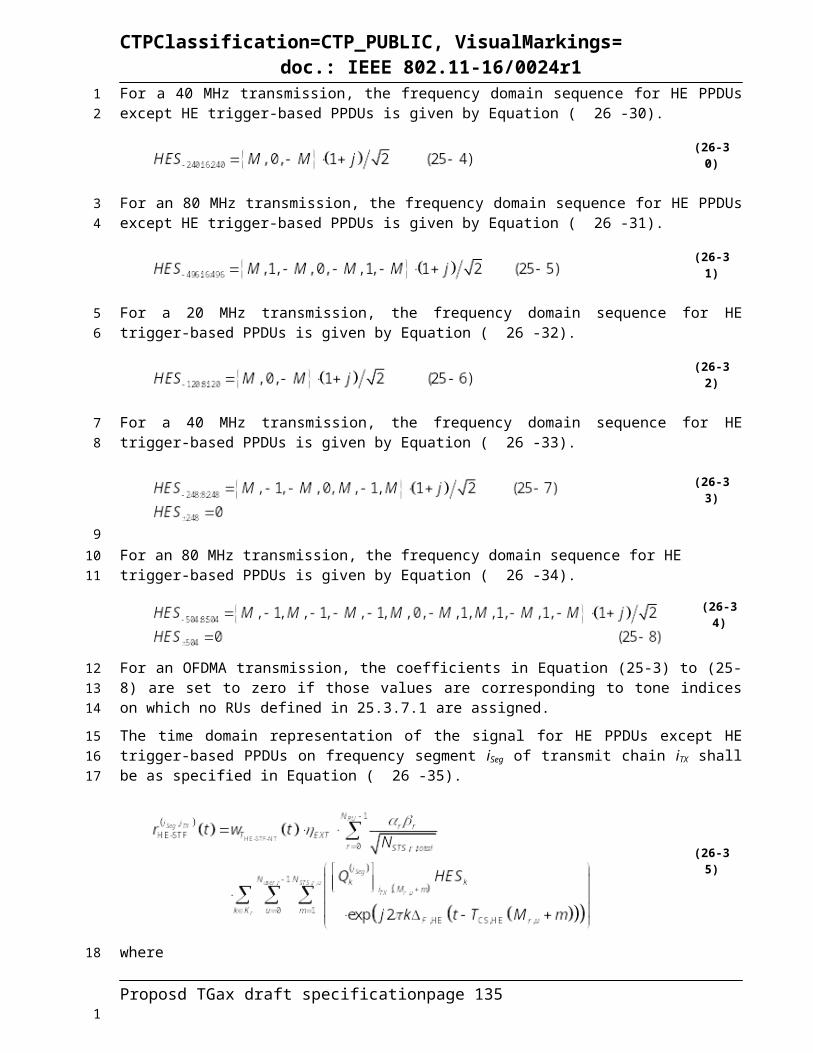
CTPClassification=CTP_PUBLIC, VisualMarkings=doc.: IEEE 802.11-16/0024r1
Table 26-40 to Table 26-95 define HE-MCSs not only for SU transmission but also for user u at r-th RU of an MU transmission. In the case of HE-MCSs for MU transmissions, the parameters, NSS, R, NBPSCS, NCBPS, NDBPS, and NES are replaced with NSS,r,u, Rr,u, NBPSCS,r,u, NCBPS,r,u, NDBPS,r,u, and NES,r,u, respectively.
In the tables below, the number of streams and RU sizes that DCM is applicable to are TBD.Table 26-40 - HE-MCSs for TBD mandatory/optional 26-tone RU, NSS = 1
0.8 usec GI
1.6 usec GI
3.2 usec GI
0 1 1/4 1 24 6 1 0.4 0.4 0.40 0 1/2 1 24 12 1 0.9 0.8 0.81 1 1/4 2 48 12 1 0.9 0.8 0.81 0 1/2 2 48 24 1 1.8 1.7 1.52 N/A 3/4 2 48 36 1 2.6 2.5 2.33 1 1/4 4 96 24 1 1.8 1.7 1.53 0 1/2 4 96 48 1 3.5 3.3 3.04 1 3/8 4 96 36 1 2.6 2.5 2.34 0 3/4 4 96 72 1 5.3 5.0 4.55 2/3 6 144 96 1 7.1 6.7 6.06 3/4 6 144 108 1 7.9 7.5 6.87 5/6 6 144 120 1 8.8 8.3 7.58 3/4 8 192 144 1 10.6 10.0 9.09 5/6 8 192 160 1 11.8 11.1 10.0
Data rate (Mb/s)
BPSK
24 2
64-QAM
256-QAM
Modulation R N BPSCS N SD N SP N CBPS N DBPS N ESHE-MCS
IndexDCM
16-QAM
QPSK
N/A
Table 26-41 HE-MCSs for TBD mandatory/optional 26-tone RU, NSS = 2
0.8 usec GI
1.6 usec GI
3.2 usec GI
0 1 1/4 1 48 12 1 0.9 0.8 0.80 0 1/2 1 48 24 1 1.8 1.7 1.51 1 1/4 2 96 24 1 1.8 1.7 1.51 0 1/2 2 96 48 1 3.5 3.3 3.02 N/A 3/4 2 96 72 1 5.3 5.0 4.53 1 1/4 4 192 48 1 3.5 3.3 3.03 0 1/2 4 192 96 1 7.1 6.7 6.04 1 3/8 4 192 72 1 5.3 5.0 4.54 0 3/4 4 192 144 1 10.6 10.0 9.05 2/3 6 288 192 1 14.1 13.3 12.06 3/4 6 288 216 1 15.9 15.0 13.57 5/6 6 288 240 1 17.6 16.7 15.08 3/4 8 384 288 1 21.2 20.0 18.09 5/6 8 384 320 1 23.5 22.2 20.0
N SD N SP N CBPS N DBPS N ES
Data rate (Mb/s)Modulation R N BPSCS
BPSK
24 2
64-QAM
256-QAM
HE-MCS Index
DCM
QPSK
16-QAM
N/A
Table 26-42 HE-MCSs for TBD mandatory/optional 26-tone RU, NSS = 3
Proposd TGax draft specification page 135
123
4
5
67
8
9
1011
12
1

CTPClassification=CTP_PUBLIC, VisualMarkings=doc.: IEEE 802.11-16/0024r1
0.8 usec GI
1.6 usec GI
3.2 usec GI
0 1 1/4 1 72 18 1 1.3 1.3 1.10 0 1/2 1 72 36 1 2.6 2.5 2.31 1 1/4 2 144 36 1 2.6 2.5 2.31 0 1/2 2 144 72 1 5.3 5.0 4.52 N/A 3/4 2 144 108 1 7.9 7.5 6.83 1 1/4 4 288 72 1 5.3 5.0 4.53 0 1/2 4 288 144 1 10.6 10.0 9.04 1 3/8 4 288 108 1 7.9 7.5 6.84 0 3/4 4 288 216 1 15.9 15.0 13.55 2/3 6 432 288 1 21.2 20.0 18.06 3/4 6 432 324 1 23.8 22.5 20.37 5/6 6 432 360 1 26.5 25.0 22.58 3/4 8 576 432 1 31.8 30.0 27.09 5/6 8 576 480 1 35.3 33.3 30.0
Data rate (Mb/s)
BPSK
24 2
64-QAM
N SP
256-QAM
HE-MCS Index
Modulation R N BPSCS N SD N CBPS N DBPS N ESDCM
QPSK
16-QAM
N/A
Table 26-43 HE-MCSs for TBD mandatory/optional 26-tone RU, NSS = 4
0.8 usec GI
1.6 usec GI
3.2 usec GI
0 1 1/4 1 96 24 1 1.8 1.7 1.50 0 1/2 1 96 48 1 3.5 3.3 3.01 1 1/4 2 192 48 1 3.5 3.3 3.01 0 1/2 2 192 96 1 7.1 6.7 6.02 N/A 3/4 2 192 144 1 10.6 10.0 9.03 1 1/4 4 384 96 1 7.1 6.7 6.03 0 1/2 4 384 192 1 14.1 13.3 12.04 1 3/8 4 384 144 1 10.6 10.0 9.04 0 3/4 4 384 288 1 21.2 20.0 18.05 2/3 6 576 384 1 28.2 26.7 24.06 3/4 6 576 432 1 31.8 30.0 27.07 5/6 6 576 480 1 35.3 33.3 30.08 3/4 8 768 576 1 42.4 40.0 36.09 5/6 8 768 640 1 47.1 44.4 40.0
HE-MCS Index
Modulation R N BPSCS
N/A
N SD N SP N CBPS N DBPS N ES
Data rate (Mb/s)DCM
16-QAM
BPSK
24
QPSK
2
64-QAM
256-QAM
Table 26-44 HE-MCSs for TBD mandatory/optional 26-tone RU, NSS = 5
Proposd TGax draft specification page 136
1
2
3
4
5
1

CTPClassification=CTP_PUBLIC, VisualMarkings=doc.: IEEE 802.11-16/0024r1
0.8 usec GI
1.6 usec GI
3.2 usec GI
0 1 1/4 1 120 30 1 2.2 2.1 1.90 0 1/2 1 120 60 1 4.4 4.2 3.81 1 1/4 2 240 60 1 4.4 4.2 3.81 0 1/2 2 240 120 1 8.8 8.3 7.52 N/A 3/4 2 240 180 1 13.2 12.5 11.33 1 1/4 4 480 120 1 8.8 8.3 7.53 0 1/2 4 480 240 1 17.6 16.7 15.04 1 3/8 4 480 180 1 13.2 12.5 11.34 0 3/4 4 480 360 1 26.5 25.0 22.55 2/3 6 720 480 1 35.3 33.3 30.06 3/4 6 720 540 1 39.7 37.5 33.87 5/6 6 720 600 1 44.1 41.7 37.58 3/4 8 960 720 1 52.9 50.0 45.09 5/6 8 960 800 1 58.8 55.6 50.0
256-QAM
N/A
2
64-QAM
N SP
QPSK
16-QAM
N CBPS N DBPS N ES
Data rate (Mb/s)HE-MCS
IndexModulation R N BPSCS N SDDCM
BPSK
24
Table 26-45 HE-MCSs for TBD mandatory/optional 26-tone RU, NSS = 6
0.8 usec GI
1.6 usec GI
3.2 usec GI
0 1 1/4 1 144 36 1 2.6 2.5 2.30 0 1/2 1 144 72 1 5.3 5.0 4.51 1 1/4 2 288 72 1 5.3 5.0 4.51 0 1/2 2 288 144 1 10.6 10.0 9.02 N/A 3/4 2 288 216 1 15.9 15.0 13.53 1 1/4 4 576 144 1 10.6 10.0 9.03 0 1/2 4 576 288 1 21.2 20.0 18.04 1 3/8 4 576 216 1 15.9 15.0 13.54 0 3/4 4 576 432 1 31.8 30.0 27.05 2/3 6 864 576 1 42.4 40.0 36.06 3/4 6 864 648 1 47.6 45.0 40.57 5/6 6 864 720 1 52.9 50.0 45.08 3/4 8 1152 864 1 63.5 60.0 54.09 5/6 8 1152 960 1 70.6 66.7 60.0
BPSK
24 2
64-QAM
256-QAM
QPSK
16-QAM
N/A
N ES
Data rate (Mb/s)HE-MCS
IndexModulation R N BPSCSDCM N SD N SP N CBPS N DBPS
Table 26-46 HE-MCSs for TBD mandatory/optional 26-tone RU, NSS = 7
Proposd TGax draft specification page 137
1
2
3
4
5
6
1

CTPClassification=CTP_PUBLIC, VisualMarkings=doc.: IEEE 802.11-16/0024r1
0.8 usec GI
1.6 usec GI
3.2 usec GI
0 1 1/4 1 168 42 1 3.1 2.9 2.60 0 1/2 1 168 84 1 6.2 5.8 5.31 1 1/4 2 336 84 1 6.2 5.8 5.31 0 1/2 2 336 168 1 12.4 11.7 10.52 N/A 3/4 2 336 252 1 18.5 17.5 15.83 1 1/4 4 672 168 1 12.4 11.7 10.53 0 1/2 4 672 336 1 24.7 23.3 21.04 1 3/8 4 672 252 1 18.5 17.5 15.84 0 3/4 4 672 504 1 37.1 35.0 31.55 2/3 6 1008 672 1 49.4 46.7 42.06 3/4 6 1008 756 1 55.6 52.5 47.37 5/6 6 1008 840 1 61.8 58.3 52.58 3/4 8 1344 1008 1 74.1 70.0 63.09 5/6 8 1344 1120 1 82.4 77.8 70.0
256-QAM
N/A
N CBPS N DBPS N ES
Data rate (Mb/s)
BPSK
24 2
64-QAM
QPSK
16-QAM
HE-MCS Index
Modulation R N BPSCS N SD N SPDCM
Table 26-47 HE-MCSs for TBD mandatory/optional 26-tone RU, NSS = 8
0.8 usec GI
1.6 usec GI
3.2 usec GI
0 1 1/4 1 192 48 1 3.5 3.3 3.00 0 1/2 1 192 96 1 7.1 6.7 6.01 1 1/4 2 384 96 1 7.1 6.7 6.01 0 1/2 2 384 192 1 14.1 13.3 12.02 N/A 3/4 2 384 288 1 21.2 20.0 18.03 1 1/4 4 768 192 1 14.1 13.3 12.03 0 1/2 4 768 384 1 28.2 26.7 24.04 1 3/8 4 768 288 1 21.2 20.0 18.04 0 3/4 4 768 576 1 42.4 40.0 36.05 2/3 6 1152 768 1 56.5 53.3 48.06 3/4 6 1152 864 1 63.5 60.0 54.07 5/6 6 1152 960 1 70.6 66.7 60.08 3/4 8 1536 1152 1 84.7 80.0 72.09 5/6 8 1536 1280 1 94.1 88.9 80.0
24 2
64-QAM
256-QAM
N SD N SP
QPSK
16-QAM
N CBPS N DBPS N ES
Data rate (Mb/s)HE-MCS
IndexModulation R N BPSCSDCM
N/A
BPSK
Table 26-48 HE-MCSs for TBD mandatory/optional 52-tone RU, NSS = 1
Proposd TGax draft specification page 138
1
2
3
4
5
6
1

CTPClassification=CTP_PUBLIC, VisualMarkings=doc.: IEEE 802.11-16/0024r1
0.8 usec GI
1.6 usec GI
3.2 usec GI
0 1 1/4 1 48 12 1 0.9 0.8 0.80 0 1/2 1 48 24 1 1.8 1.7 1.51 1 1/4 2 96 24 1 1.8 1.7 1.51 0 1/2 2 96 48 1 3.5 3.3 3.02 N/A 3/4 2 96 72 1 5.3 5.0 4.53 1 1/4 4 192 48 1 3.5 3.3 3.03 0 1/2 4 192 96 1 7.1 6.7 6.04 1 3/8 4 192 72 1 5.3 5.0 4.54 0 3/4 4 192 144 1 10.6 10.0 9.05 2/3 6 288 192 1 14.1 13.3 12.06 3/4 6 288 216 1 15.9 15.0 13.57 5/6 6 288 240 1 17.6 16.7 15.08 3/4 8 384 288 1 21.2 20.0 18.09 5/6 8 384 320 1 23.5 22.2 20.0
Data rate (Mb/s)
BPSK
48 4
64-QAM
256-QAM
Modulation R N BPSCS N SD N SP N CBPS N DBPS N ESHE-MCS
IndexDCM
QPSK
16-QAM
N/A
Table 26-49 HE-MCSs for TBD mandatory/optional 52-tone RU, NSS = 2
0.8 usec GI
1.6 usec GI
3.2 usec GI
0 1 1/4 1 96 24 1 1.8 1.7 1.50 0 1/2 1 96 48 1 3.5 3.3 3.01 1 1/4 2 192 48 1 3.5 3.3 3.01 0 1/2 2 192 96 1 7.1 6.7 6.02 N/A 3/4 2 192 144 1 10.6 10.0 9.03 1 1/4 4 384 96 1 7.1 6.7 6.03 0 1/2 4 384 192 1 14.1 13.3 12.04 1 3/8 4 384 144 1 10.6 10.0 9.04 0 3/4 4 384 288 1 21.2 20.0 18.05 2/3 6 576 384 1 28.2 26.7 24.06 3/4 6 576 432 1 31.8 30.0 27.07 5/6 6 576 480 1 35.3 33.3 30.08 3/4 8 768 576 1 42.4 40.0 36.09 5/6 8 768 640 1 47.1 44.4 40.0
N SD N SP N CBPS N DBPS N ES
Data rate (Mb/s)Modulation R N BPSCS
BPSK
48 4
64-QAM
256-QAM
HE-MCS Index
DCM
QPSK
16-QAM
N/A
Table 26-50 HE-MCSs for TBD mandatory/optional 52-tone RU, NSS = 3
Proposd TGax draft specification page 139
1
2
3
4
5
6
1

CTPClassification=CTP_PUBLIC, VisualMarkings=doc.: IEEE 802.11-16/0024r1
0.8 usec GI
1.6 usec GI
3.2 usec GI
0 1 1/4 1 144 36 1 2.6 2.5 2.30 0 1/2 1 144 72 1 5.3 5.0 4.51 1 1/4 2 288 72 1 5.3 5.0 4.51 0 1/2 2 288 144 1 10.6 10.0 9.02 N/A 3/4 2 288 216 1 15.9 15.0 13.53 1 1/4 4 576 144 1 10.6 10.0 9.03 0 1/2 4 576 288 1 21.2 20.0 18.04 1 3/8 4 576 216 1 15.9 15.0 13.54 0 3/4 4 576 432 1 31.8 30.0 27.05 2/3 6 864 576 1 42.4 40.0 36.06 3/4 6 864 648 1 47.6 45.0 40.57 5/6 6 864 720 1 52.9 50.0 45.08 3/4 8 1152 864 1 63.5 60.0 54.09 5/6 8 1152 960 1 70.6 66.7 60.0
Data rate (Mb/s)
BPSK
48 4
64-QAM
N SP
256-QAM
N CBPS N DBPS N ES
QPSK
16-QAM
HE-MCS Index
Modulation R N BPSCS N SDDCM
N/A
Table 26-51 HE-MCSs for TBD mandatory/optional 52-tone RU, NSS = 4
0.8 usec GI
1.6 usec GI
3.2 usec GI
0 1 1/4 1 192 48 1 3.5 3.3 3.00 0 1/2 1 192 96 1 7.1 6.7 6.01 1 1/4 2 384 96 1 7.1 6.7 6.01 0 1/2 2 384 192 1 14.1 13.3 12.02 N/A 3/4 2 384 288 1 21.2 20.0 18.03 1 1/4 4 768 192 1 14.1 13.3 12.03 0 1/2 4 768 384 1 28.2 26.7 24.04 1 3/8 4 768 288 1 21.2 20.0 18.04 0 3/4 4 768 576 1 42.4 40.0 36.05 2/3 6 1152 768 1 56.5 53.3 48.06 3/4 6 1152 864 1 63.5 60.0 54.07 5/6 6 1152 960 1 70.6 66.7 60.08 3/4 8 1536 1152 1 84.7 80.0 72.09 5/6 8 1536 1280 1 94.1 88.9 80.0
4
64-QAM
256-QAM
HE-MCS Index
Modulation R N BPSCS
QPSK
16-QAM
N/A
BPSK
48
N SD N SP N CBPS N DBPS N ES
Data rate (Mb/s)DCM
Table 26-52 HE-MCSs for TBD mandatory/optional 52-tone RU, NSS = 5
Proposd TGax draft specification page 140
1
2
3
4
5
6
1

CTPClassification=CTP_PUBLIC, VisualMarkings=doc.: IEEE 802.11-16/0024r1
0.8 usec GI
1.6 usec GI
3.2 usec GI
0 1 1/4 1 240 60 1 4.4 4.2 3.80 0 1/2 1 240 120 1 8.8 8.3 7.51 1 1/4 2 480 120 1 8.8 8.3 7.51 0 1/2 2 480 240 1 17.6 16.7 15.02 N/A 3/4 2 480 360 1 26.5 25.0 22.53 1 1/4 4 960 240 1 17.6 16.7 15.03 0 1/2 4 960 480 1 35.3 33.3 30.04 1 3/8 4 960 360 1 26.5 25.0 22.54 0 3/4 4 960 720 1 52.9 50.0 45.05 2/3 6 1440 960 1 70.6 66.7 60.06 3/4 6 1440 1080 1 79.4 75.0 67.57 5/6 6 1440 1200 1 88.2 83.3 75.08 3/4 8 1920 1440 1 105.9 100.0 90.09 5/6 8 1920 1600 1 117.6 111.1 100.0
N DBPS N ES
Data rate (Mb/s)
BPSK
48 4
64-QAM
N SP
256-QAM
N CBPSHE-MCS
IndexModulation R N BPSCS N SDDCM
QPSK
16-QAM
N/A
Table 26-53 HE-MCSs for TBD mandatory/optional 52-tone RU, NSS = 6
0.8 usec GI
1.6 usec GI
3.2 usec GI
0 1 1/4 1 288 72 1 5.3 5.0 4.50 0 1/2 1 288 144 1 10.6 10.0 9.01 1 1/4 2 576 144 1 10.6 10.0 9.01 0 1/2 2 576 288 1 21.2 20.0 18.02 N/A 3/4 2 576 432 1 31.8 30.0 27.03 1 1/4 4 1152 288 1 21.2 20.0 18.03 0 1/2 4 1152 576 1 42.4 40.0 36.04 1 3/8 4 1152 432 1 31.8 30.0 27.04 0 3/4 4 1152 864 1 63.5 60.0 54.05 2/3 6 1728 1152 1 84.7 80.0 72.06 3/4 6 1728 1296 1 95.3 90.0 81.07 5/6 6 1728 1440 1 105.9 100.0 90.08 3/4 8 2304 1728 1 127.1 120.0 108.09 5/6 8 2304 1920 1 141.2 133.3 120.0
48 4
64-QAM
256-QAM
HE-MCS Index
Modulation R N BPSCS N SD N SP N CBPS N DBPS N ES
Data rate (Mb/s)DCM
QPSK
16-QAM
N/A
BPSK
Table 26-54 HE-MCSs for TBD mandatory/optional 52-tone RU, NSS = 7
Proposd TGax draft specification page 141
1
2
3
4
5
6
1

CTPClassification=CTP_PUBLIC, VisualMarkings=doc.: IEEE 802.11-16/0024r1
0.8 usec GI
1.6 usec GI
3.2 usec GI
0 1 1/4 1 336 84 1 6.2 5.8 5.30 0 1/2 1 336 168 1 12.4 11.7 10.51 1 1/4 2 672 168 1 12.4 11.7 10.51 0 1/2 2 672 336 1 24.7 23.3 21.02 N/A 3/4 2 672 504 1 37.1 35.0 31.53 1 1/4 4 1344 336 1 24.7 23.3 21.03 0 1/2 4 1344 672 1 49.4 46.7 42.04 1 3/8 4 1344 504 1 37.1 35.0 31.54 0 3/4 4 1344 1008 1 74.1 70.0 63.05 2/3 6 2016 1344 1 98.8 93.3 84.06 3/4 6 2016 1512 1 111.2 105.0 94.57 5/6 6 2016 1680 1 123.5 116.7 105.08 3/4 8 2688 2016 1 148.2 140.0 126.09 5/6 8 2688 2240 1 164.7 155.6 140.0
N/A
N ES
Data rate (Mb/s)
BPSK
48 4
64-QAM
QPSK
16-QAM
256-QAM
N SP N CBPS N DBPSHE-MCS
IndexModulation R N BPSCS N SDDCM
Table 26-55 HE-MCSs for TBD mandatory/optional 52-tone RU, NSS = 8
0.8 usec GI
1.6 usec GI
3.2 usec GI
0 1 1/4 1 384 96 1 7.1 6.7 6.00 0 1/2 1 384 192 1 14.1 13.3 12.01 1 1/4 2 768 192 1 14.1 13.3 12.01 0 1/2 2 768 384 1 28.2 26.7 24.02 N/A 3/4 2 768 576 1 42.4 40.0 36.03 1 1/4 4 1536 384 1 28.2 26.7 24.03 0 1/2 4 1536 768 1 56.5 53.3 48.04 1 3/8 4 1536 576 1 42.4 40.0 36.04 0 3/4 4 1536 1152 1 84.7 80.0 72.05 2/3 6 2304 1536 1 112.9 106.7 96.06 3/4 6 2304 1728 1 127.1 120.0 108.07 5/6 6 2304 1920 1 141.2 133.3 120.08 3/4 8 3072 2304 1 169.4 160.0 144.09 5/6 8 3072 2560 1 188.2 177.8 160.0
HE-MCS Index
Modulation R N BPSCSDCM
BPSK
48 4
64-QAM
256-QAM
N SD N SP
QPSK
16-QAM
N CBPS N DBPS N ES
Data rate (Mb/s)
N/A
Table 26-56 HE-MCSs for TBD mandatory/optional 106-tone RU, NSS = 1
Proposd TGax draft specification page 142
1
2
3
4
5
6
1
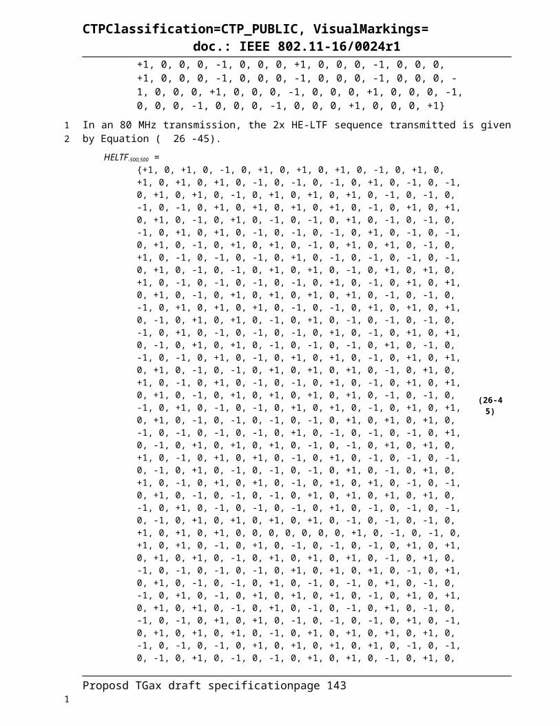
CTPClassification=CTP_PUBLIC, VisualMarkings=doc.: IEEE 802.11-16/0024r1
0.8 usec GI
1.6 usec GI
3.2 usec GI
0 1 1/4 1 102 25 1 1.8 1.7 1.60 0 1/2 1 102 51 1 3.8 3.5 3.21 1 1/4 2 204 51 1 3.8 3.5 3.21 0 1/2 2 204 102 1 7.5 7.1 6.42 N/A 3/4 2 204 153 1 11.3 10.6 9.63 1 1/4 4 408 102 1 7.5 7.1 6.43 0 1/2 4 408 204 1 15.0 14.2 12.84 1 3/8 4 408 153 1 11.3 10.6 9.64 0 3/4 4 408 306 1 22.5 21.3 19.15 2/3 6 612 408 1 30.0 28.3 25.56 3/4 6 612 459 1 33.8 31.9 28.77 5/6 6 612 510 1 37.5 35.4 31.98 3/4 8 816 612 1 45.0 42.5 38.39 5/6 8 816 680 1 50.0 47.2 42.5
Data rate (Mb/s)
BPSK
102 4
64-QAM
256-QAM
Modulation R N BPSCS N SD N SP N CBPS N DBPS N ESHE-MCS
IndexDCM
QPSK
16-QAM
N/A
Table 26-57 HE-MCSs for TBD mandatory/optional 106-tone RU, NSS = 2
0.8 usec GI
1.6 usec GI
3.2 usec GI
0 1 1/4 1 204 51 1 3.8 3.5 3.20 0 1/2 1 204 102 1 7.5 7.1 6.41 1 1/4 2 408 102 1 7.5 7.1 6.41 0 1/2 2 408 204 1 15.0 14.2 12.82 N/A 3/4 2 408 306 1 22.5 21.3 19.13 1 1/4 4 816 204 1 15.0 14.2 12.83 0 1/2 4 816 408 1 30.0 28.3 25.54 1 3/8 4 816 306 1 22.5 21.3 19.14 0 3/4 4 816 612 1 45.0 42.5 38.35 2/3 6 1224 816 1 60.0 56.7 51.06 3/4 6 1224 918 1 67.5 63.8 57.47 5/6 6 1224 1,020 1 75.0 70.8 63.88 3/4 8 1632 1,224 1 90.0 85.0 76.59 5/6 8 1632 1,360 1 100.0 94.4 85.0
N SD N SP N CBPS N DBPS N ES
Data rate (Mb/s)Modulation R N BPSCS
BPSK
102 4
256-QAM
HE-MCS Index
DCM
QPSK
16-QAM
N/A64-QAM
Table 26-58 HE-MCSs for TBD mandatory/optional 106-tone RU, NSS = 3
Proposd TGax draft specification page 143
1
2
3
4
5
6
7
1

CTPClassification=CTP_PUBLIC, VisualMarkings=doc.: IEEE 802.11-16/0024r1
0.8 usec GI
1.6 usec GI
3.2 usec GI
0 1 1/4 1 306 76 1 5.6 5.3 4.80 0 1/2 1 306 153 1 11.3 10.6 9.61 1 1/4 2 612 153 1 11.3 10.6 9.61 0 1/2 2 612 306 1 22.5 21.3 19.12 N/A 3/4 2 612 459 1 33.8 31.9 28.73 1 1/4 4 1224 306 1 22.5 21.3 19.13 0 1/2 4 1224 612 1 45.0 42.5 38.34 1 3/8 4 1224 459 1 33.8 31.9 28.74 0 3/4 4 1224 918 1 67.5 63.8 57.45 2/3 6 1836 1,224 1 90.0 85.0 76.56 3/4 6 1836 1,377 1 101.3 95.6 86.17 5/6 6 1836 1,530 1 112.5 106.3 95.68 3/4 8 2448 1,836 1 135.0 127.5 114.89 5/6 8 2448 2,040 1 150.0 141.7 127.5
Data rate (Mb/s)
BPSK
102 4
64-QAM
N SP
256-QAM
N/A
HE-MCS Index
Modulation R N BPSCS N SD N CBPS N DBPS N ESDCM
QPSK
16-QAM
Table 26-59 HE-MCSs for TBD mandatory/optional 106-tone RU, NSS = 4
0.8 usec GI
1.6 usec GI
3.2 usec GI
0 1 1/4 1 408 102 1 7.5 7.1 6.40 0 1/2 1 408 204 1 15.0 14.2 12.81 1 1/4 2 816 204 1 15.0 14.2 12.81 0 1/2 2 816 408 1 30.0 28.3 25.52 N/A 3/4 2 816 612 1 45.0 42.5 38.33 1 1/4 4 1632 408 1 30.0 28.3 25.53 0 1/2 4 1632 816 1 60.0 56.7 51.04 1 3/8 4 1632 612 1 45.0 42.5 38.34 0 3/4 4 1632 1,224 1 90.0 85.0 76.55 2/3 6 2448 1,632 1 120.0 113.3 102.06 3/4 6 2448 1,836 1 135.0 127.5 114.87 5/6 6 2448 2,040 1 150.0 141.7 127.58 3/4 8 3264 2,448 1 180.0 170.0 153.09 5/6 8 3264 2,720 1 200.0 188.9 170.0
4
64-QAM
256-QAM
HE-MCS Index
Modulation R N BPSCS
16-QAM
N/A
N SD N SP N CBPS N DBPS N ES
Data rate (Mb/s)DCM
QPSK
BPSK
102
Table 26-60 HE-MCSs for TBD mandatory/optional 106-tone RU, NSS = 5
Proposd TGax draft specification page 144
1
2
3
4
5
6
7
1

CTPClassification=CTP_PUBLIC, VisualMarkings=doc.: IEEE 802.11-16/0024r1
0.8 usec GI
1.6 usec GI
3.2 usec GI
0 1 1/4 1 510 127 1 9.3 8.8 7.90 0 1/2 1 510 255 1 18.8 17.7 15.91 1 1/4 2 1020 255 1 18.8 17.7 15.91 0 1/2 2 1020 510 1 37.5 35.4 31.92 N/A 3/4 2 1020 765 1 56.3 53.1 47.83 1 1/4 4 2040 510 1 37.5 35.4 31.93 0 1/2 4 2040 1,020 1 75.0 70.8 63.84 1 3/8 4 2040 765 1 56.3 53.1 47.84 0 3/4 4 2040 1,530 1 112.5 106.3 95.65 2/3 6 3060 2,040 1 150.0 141.7 127.56 3/4 6 3060 2,295 1 168.8 159.4 143.47 5/6 6 3060 2,550 1 187.5 177.1 159.48 3/4 8 4080 3,060 1 225.0 212.5 191.39 5/6 8 4080 3,400 1 250.0 236.1 212.5
256-QAM
N CBPS N DBPS N ES
Data rate (Mb/s)
BPSK
102 4
64-QAM
N SPHE-MCS
IndexModulation R N BPSCS N SDDCM
QPSK
16-QAM
N/A
Table 26-61 HE-MCSs for TBD mandatory/optional 106-tone RU, NSS = 6
0.8 usec GI
1.6 usec GI
3.2 usec GI
0 1 1/4 1 612 153 1 11.3 10.6 9.60 0 1/2 1 612 306 1 22.5 21.3 19.11 1 1/4 2 1224 306 1 22.5 21.3 19.11 0 1/2 2 1224 612 1 45.0 42.5 38.32 N/A 3/4 2 1224 918 1 67.5 63.8 57.43 1 1/4 4 2448 612 1 45.0 42.5 38.33 0 1/2 4 2448 1,224 1 90.0 85.0 76.54 1 3/8 4 2448 918 1 67.5 63.8 57.44 0 3/4 4 2448 1,836 1 135.0 127.5 114.85 2/3 6 3672 2,448 1 180.0 170.0 153.06 3/4 6 3672 2,754 1 202.5 191.3 172.17 5/6 6 3672 3,060 1 225.0 212.5 191.38 3/4 8 4896 3,672 1 270.0 255.0 229.59 5/6 8 4896 4,080 1 300.0 283.3 255.0
BPSK
102 4
64-QAM
256-QAM
N SD N SP N CBPS N DBPS N ES
Data rate (Mb/s)HE-MCS
IndexModulation R N BPSCSDCM
QPSK
16-QAM
N/A
Table 26-62 HE-MCSs for TBD mandatory/optional 106-tone RU, NSS = 7
Proposd TGax draft specification page 145
1
2
3
4
5
6
7
1

CTPClassification=CTP_PUBLIC, VisualMarkings=doc.: IEEE 802.11-16/0024r1
0.8 usec GI
1.6 usec GI
3.2 usec GI
0 1 1/4 1 714 178 1 13.1 12.4 11.10 0 1/2 1 714 357 1 26.3 24.8 22.31 1 1/4 2 1428 357 1 26.3 24.8 22.31 0 1/2 2 1428 714 1 52.5 49.6 44.62 N/A 3/4 2 1428 1,071 1 78.8 74.4 66.93 1 1/4 4 2856 714 1 52.5 49.6 44.63 0 1/2 4 2856 1,428 1 105.0 99.2 89.34 1 3/8 4 2856 1,071 1 78.8 74.4 66.94 0 3/4 4 2856 2,142 1 157.5 148.8 133.95 2/3 6 4284 2,856 1 210.0 198.3 178.56 3/4 6 4284 3,213 1 236.3 223.1 200.87 5/6 6 4284 3,570 1 262.5 247.9 223.18 3/4 8 5712 4,284 1 315.0 297.5 267.89 5/6 8 5712 4,760 1 350.0 330.6 297.5
256-QAM
N/A
N CBPS N DBPS N ES
Data rate (Mb/s)
BPSK
102 4
64-QAM
QPSK
16-QAM
HE-MCS Index
Modulation R N BPSCS N SD N SPDCM
Table 26-63 HE-MCSs for TBD mandatory/optional 106-tone RU, NSS = 8
0.8 usec GI
1.6 usec GI
3.2 usec GI
0 1 1/4 1 816 204 1 15.0 14.2 12.80 0 1/2 1 816 408 1 30.0 28.3 25.51 1 1/4 2 1632 408 1 30.0 28.3 25.51 0 1/2 2 1632 816 1 60.0 56.7 51.02 N/A 3/4 2 1632 1,224 1 90.0 85.0 76.53 1 1/4 4 3264 816 1 60.0 56.7 51.03 0 1/2 4 3264 1,632 1 120.0 113.3 102.04 1 3/8 4 3264 1,224 1 90.0 85.0 76.54 0 3/4 4 3264 2,448 1 180.0 170.0 153.05 2/3 6 4896 3,264 1 240.0 226.7 204.06 3/4 6 4896 3,672 1 270.0 255.0 229.57 5/6 6 4896 4,080 1 300.0 283.3 255.08 3/4 8 6528 4,896 1 360.0 340.0 306.09 5/6 8 6528 5,440 1 400.0 377.8 340.0
102 4
64-QAM
256-QAM
N SD N SP
QPSK
16-QAM
N CBPS N DBPS N ES
Data rate (Mb/s)HE-MCS
IndexModulation R N BPSCSDCM
N/A
BPSK
Table 26-64 HE-MCSs for TBD mandatory/optional 242-tone RU and mandatory non-OFDMA 20MHz, NSS = 1
Proposd TGax draft specification page 146
1
2
3
4
5
6
7
1

CTPClassification=CTP_PUBLIC, VisualMarkings=doc.: IEEE 802.11-16/0024r1
0.8 usec GI
1.6 usec GI
3.2 usec GI
0 1 1/4 1 234 58 1 4.3 4.0 3.60 0 1/2 1 234 117 1 8.6 8.1 7.31 1 1/4 2 468 117 1 8.6 8.1 7.31 0 1/2 2 468 234 1 17.2 16.3 14.62 N/A 3/4 2 468 351 1 25.8 24.4 21.93 1 1/4 4 936 234 1 17.2 16.3 14.63 0 1/2 4 936 468 1 34.4 32.5 29.34 1 3/8 4 936 351 1 25.8 24.4 21.94 0 3/4 4 936 702 1 51.6 48.8 43.95 2/3 6 1404 936 1 68.8 65.0 58.56 3/4 6 1404 1,053 1 77.4 73.1 65.87 5/6 6 1404 1,170 1 86.0 81.3 73.18 3/4 8 1872 1,404 1 103.2 97.5 87.89 5/6 8 1872 1,560 1 114.7 108.3 97.5
10 3/4 10 2340 1,755 1 129.0 121.9 109.711 5/6 10 2340 1,950 1 143.4 135.4 121.9
QPSK
16-QAM
N/A
Data rate (Mb/s)N ESN SP N CBPS N DBPS
HE-MCS Index
Modulation R N BPSCS N SDDCM
234 8
BPSK
64-QAM
256-QAM
1024-QAM
Table 26-65 HE-MCSs for TBD mandatory/optional 242-tone RU and mandatory non-OFDMA 20MHz, NSS = 2
0.8 usec GI
1.6 usec GI
3.2 usec GI
0 1 1/4 1 468 117 1 8.6 8.1 7.30 0 1/2 1 468 234 1 17.2 16.3 14.61 1 1/4 2 936 234 1 17.2 16.3 14.61 0 1/2 2 936 468 1 34.4 32.5 29.32 N/A 3/4 2 936 702 1 51.6 48.8 43.93 1 1/4 4 1872 468 1 34.4 32.5 29.33 0 1/2 4 1872 936 1 68.8 65.0 58.54 1 3/8 4 1872 702 1 51.6 48.8 43.94 0 3/4 4 1872 1,404 1 103.2 97.5 87.85 2/3 6 2808 1,872 1 137.6 130.0 117.06 3/4 6 2808 2,106 1 154.9 146.3 131.67 5/6 6 2808 2,340 1 172.1 162.5 146.38 3/4 8 3744 2,808 1 206.5 195.0 175.59 5/6 8 3744 3,120 1 229.4 216.7 195.0
10 3/4 10 4680 3,510 1 258.1 243.8 219.411 5/6 10 4680 3,900 1 286.8 270.8 243.8
256-QAM
1024-QAM
N/A
DCM N CBPS N DBPS N ES
Data rate (Mb/s)
BPSK
234 8
64-QAM
QPSK
16-QAM
HE-MCS Index
Modulation R N BPSCS N SD N SP
Table 26-66 HE-MCSs for TBD mandatory/optional 242-tone RU and mandatory non-OFDMA 20MHz, NSS = 3
Proposd TGax draft specification page 147
1
2
3
4
1

CTPClassification=CTP_PUBLIC, VisualMarkings=doc.: IEEE 802.11-16/0024r1
0.8 usec GI
1.6 usec GI
3.2 usec GI
0 1 1/4 1 702 175 1 12.9 12.2 10.90 0 1/2 1 702 351 1 25.8 24.4 21.91 1 1/4 2 1404 351 1 25.8 24.4 21.91 0 1/2 2 1404 702 1 51.6 48.8 43.92 N/A 3/4 2 1404 1,053 1 77.4 73.1 65.83 1 1/4 4 2808 702 1 51.6 48.8 43.93 0 1/2 4 2808 1,404 1 103.2 97.5 87.84 1 3/8 4 2808 1,053 1 77.4 73.1 65.84 0 3/4 4 2808 2,106 1 154.9 146.3 131.65 2/3 6 4212 2,808 1 206.5 195.0 175.56 3/4 6 4212 3,159 1 232.3 219.4 197.47 5/6 6 4212 3,510 1 258.1 243.8 219.48 3/4 8 5616 4,212 1 309.7 292.5 263.39 5/6 8 5616 4,680 1 344.1 325.0 292.5
10 3/4 10 7020 5,265 1 387.1 365.6 329.111 5/6 10 7020 5,850 1 430.1 406.3 365.6
BPSK
234 8
64-QAM
256-QAM
1024-QAM
QPSK
16-QAM
N/A
N SD N SP N CBPS N DBPS N ES
Data rate (Mb/s)HE-MCS
IndexModulation R N BPSCSDCM
Table 26-67 HE-MCSs for TBD mandatory/optional 242-tone RU and mandatory non-OFDMA 20MHz, NSS = 4
0.8 usec GI
1.6 usec GI
3.2 usec GI
0 1 1/4 1 936 234 1 17.2 16.3 14.60 0 1/2 1 936 468 1 34.4 32.5 29.31 1 1/4 2 1872 468 1 34.4 32.5 29.31 0 1/2 2 1872 936 1 68.8 65.0 58.52 N/A 3/4 2 1872 1,404 1 103.2 97.5 87.83 1 1/4 4 3744 936 1 68.8 65.0 58.53 0 1/2 4 3744 1,872 1 137.6 130.0 117.04 1 3/8 4 3744 1,404 1 103.2 97.5 87.84 0 3/4 4 3744 2,808 1 206.5 195.0 175.55 2/3 6 5616 3,744 1 275.3 260.0 234.06 3/4 6 5616 4,212 1 309.7 292.5 263.37 5/6 6 5616 4,680 1 344.1 325.0 292.58 3/4 8 7488 5,616 1 412.9 390.0 351.09 5/6 8 7488 6,240 1 458.8 433.3 390.0
10 3/4 10 9360 7,020 1 516.2 487.5 438.811 5/6 10 9360 7,800 1 573.5 541.7 487.5
256-QAM
1024-QAM
N/A
N CBPS N DBPS N ES
Data rate (Mb/s)
BPSK
234 8
64-QAM
QPSK
16-QAM
HE-MCS Index
Modulation R N BPSCS N SD N SPDCM
Table 26-68 HE-MCSs for TBD mandatory/optional 242-tone RU and mandatory non-OFDMA 20MHz, NSS = 5
Proposd TGax draft specification page 148
1
2
3
4
1
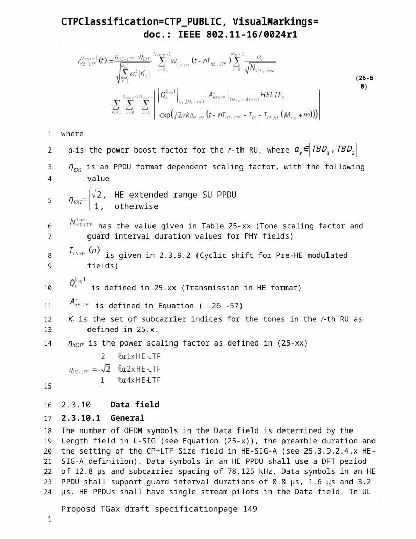
CTPClassification=CTP_PUBLIC, VisualMarkings=doc.: IEEE 802.11-16/0024r1
0.8 usec GI
1.6 usec GI
3.2 usec GI
0 1 1/4 1 1170 292 1 21.5 20.3 18.30 0 1/2 1 1170 585 1 43.0 40.6 36.61 1 1/4 2 2340 585 1 43.0 40.6 36.61 0 1/2 2 2340 1,170 1 86.0 81.3 73.12 N/A 3/4 2 2340 1,755 1 129.0 121.9 109.73 1 1/4 4 4680 1,170 1 86.0 81.3 73.13 0 1/2 4 4680 2,340 1 172.1 162.5 146.34 1 3/8 4 4680 1,755 1 129.0 121.9 109.74 0 3/4 4 4680 3,510 1 258.1 243.8 219.45 2/3 6 7020 4,680 1 344.1 325.0 292.56 3/4 6 7020 5,265 1 387.1 365.6 329.17 5/6 6 7020 5,850 1 430.1 406.3 365.68 3/4 8 9360 7,020 1 516.2 487.5 438.89 5/6 8 9360 7,800 1 573.5 541.7 487.5
10 3/4 10 11700 8,775 1 645.2 609.4 548.411 5/6 10 11700 9,750 1 716.9 677.1 609.4
BPSK
234 8
64-QAM
256-QAM
1024-QAM
QPSK
16-QAM
N/A
N SD N SP N CBPS N DBPS N ES
Data rate (Mb/s)HE-MCS
IndexModulation R N BPSCSDCM
Table 26-69 HE-MCSs for TBD mandatory/optional 242-tone RU and mandatory non-OFDMA 20MHz, NSS = 6
0.8 usec GI
1.6 usec GI
3.2 usec GI
0 1 1/4 1 1404 351 1 25.8 24.4 21.90 0 1/2 1 1404 702 1 51.6 48.8 43.91 1 1/4 2 2808 702 1 51.6 48.8 43.91 0 1/2 2 2808 1,404 1 103.2 97.5 87.82 N/A 3/4 2 2808 2,106 1 154.9 146.3 131.63 1 1/4 4 5616 1,404 1 103.2 97.5 87.83 0 1/2 4 5616 2,808 1 206.5 195.0 175.54 1 3/8 4 5616 2,106 1 154.9 146.3 131.64 0 3/4 4 5616 4,212 1 309.7 292.5 263.35 2/3 6 8424 5,616 1 412.9 390.0 351.06 3/4 6 8424 6,318 1 464.6 438.8 394.97 5/6 6 8424 7,020 1 516.2 487.5 438.88 3/4 8 11232 8,424 1 619.4 585.0 526.59 5/6 8 11232 9,360 1 688.2 650.0 585.0
10 3/4 10 14040 10,530 1 774.3 731.3 658.111 5/6 10 14040 11,700 1 860.3 812.5 731.3
256-QAM
1024-QAM
N/A
N CBPS N DBPS N ES
Data rate (Mb/s)
BPSK
234 8
64-QAM
QPSK
16-QAM
HE-MCS Index
Modulation R N BPSCS N SD N SPDCM
Table 26-70 HE-MCSs for TBD mandatory/optional 242-tone RU and mandatory non-OFDMA 20MHz, NSS = 7
Proposd TGax draft specification page 149
1
2
3
4
1

CTPClassification=CTP_PUBLIC, VisualMarkings=doc.: IEEE 802.11-16/0024r1
0.8 usec GI
1.6 usec GI
3.2 usec GI
0 1 1/4 1 1638 409 1 30.1 28.4 25.60 0 1/2 1 1638 819 1 60.2 56.9 51.21 1 1/4 2 3276 819 1 60.2 56.9 51.21 0 1/2 2 3276 1,638 1 120.4 113.8 102.42 N/A 3/4 2 3276 2,457 1 180.7 170.6 153.63 1 1/4 4 6552 1,638 1 120.4 113.8 102.43 0 1/2 4 6552 3,276 1 240.9 227.5 204.84 1 3/8 4 6552 2,457 1 180.7 170.6 153.64 0 3/4 4 6552 4,914 1 361.3 341.3 307.15 2/3 6 9828 6,552 1 481.8 455.0 409.56 3/4 6 9828 7,371 1 542.0 511.9 460.77 5/6 6 9828 8,190 1 602.2 568.8 511.98 3/4 8 13104 9,828 1 722.6 682.5 614.39 5/6 8 13104 10,920 1 802.9 758.3 682.5
10 3/4 10 16380 12,285 1 903.3 853.1 767.811 5/6 10 16380 13,650 1 1,003.7 947.9 853.1
BPSK
234 8
64-QAM
256-QAM
1024-QAM
QPSK
16-QAM
N/A
N SD N SP N CBPS N DBPS N ES
Data rate (Mb/s)HE-MCS
IndexModulation R N BPSCSDCM
Table 26-71 HE-MCSs for TBD mandatory/optional 242-tone RU and mandatory non-OFDMA 20MHz, NSS = 8
0.8 usec GI
1.6 usec GI
3.2 usec GI
0 1 1/4 1 1872 468 1 34.4 32.5 29.30 0 1/2 1 1872 936 1 68.8 65.0 58.51 1 1/4 2 3744 936 1 68.8 65.0 58.51 0 1/2 2 3744 1,872 1 137.6 130.0 117.02 N/A 3/4 2 3744 2,808 1 206.5 195.0 175.53 1 1/4 4 7488 1,872 1 137.6 130.0 117.03 0 1/2 4 7488 3,744 1 275.3 260.0 234.04 1 3/8 4 7488 2,808 1 206.5 195.0 175.54 0 3/4 4 7488 5,616 1 412.9 390.0 351.05 2/3 6 11232 7,488 1 550.6 520.0 468.06 3/4 6 11232 8,424 1 619.4 585.0 526.57 5/6 6 11232 9,360 1 688.2 650.0 585.08 3/4 8 14976 11,232 1 825.9 780.0 702.09 5/6 8 14976 12,480 1 917.6 866.7 780.0
10 3/4 10 18720 14,040 1 1,032.4 975.0 877.511 5/6 10 18720 15,600 1 1,147.1 1,083.3 975.0
256-QAM
1024-QAM
N CBPS N DBPS N ES
Data rate (Mb/s)
BPSK
234 8
64-QAM
QPSK
16-QAM
HE-MCS Index
Modulation R N BPSCS N SD N SPDCM
N/A
Table 26-72 HE-MCSs for TBD mandatory/optional 484-tone RU and mandatory non-OFDMA 40MHz, NSS = 1
Proposd TGax draft specification page 150
1
2
3
4
1

CTPClassification=CTP_PUBLIC, VisualMarkings=doc.: IEEE 802.11-16/0024r1
0.8 usec GI
1.6 usec GI
3.2 usec GI
0 1 1/4 1 468 117 1 8.6 8.1 7.30 0 1/2 1 468 234 1 17.2 16.3 14.61 1 1/4 2 936 234 1 17.2 16.3 14.61 0 1/2 2 936 468 1 34.4 32.5 29.32 N/A 3/4 2 936 702 1 51.6 48.8 43.93 1 1/4 4 1872 468 1 34.4 32.5 29.33 0 1/2 4 1872 936 1 68.8 65.0 58.54 1 3/8 4 1872 702 1 51.6 48.8 43.94 0 3/4 4 1872 1,404 1 103.2 97.5 87.85 2/3 6 2808 1,872 1 137.6 130.0 117.06 3/4 6 2808 2,106 1 154.9 146.3 131.67 5/6 6 2808 2,340 1 172.1 162.5 146.38 3/4 8 3744 2,808 1 206.5 195.0 175.59 5/6 8 3744 3,120 1 229.4 216.7 195.010 3/4 10 4680 3,510 1 258.1 243.8 219.411 5/6 10 4680 3,900 1 286.8 270.8 243.8
Data rate (Mb/s)
BPSK
468 16
64-QAM
256-QAM
1024-QAM
Modulation R N BPSCS N SD N SP N CBPS N DBPS N ESHE-MCS
IndexDCM
QPSK
16-QAM
N/A
Table 26-73 HE-MCSs for TBD mandatory/optional 484-tone RU and mandatory non-OFDMA 40MHz, NSS = 2
0.8 usec GI
1.6 usec GI
3.2 usec GI
0 1 1/4 1 936 234 1 17.2 16.3 14.60 0 1/2 1 936 468 1 34.4 32.5 29.31 1 1/4 2 1872 468 1 34.4 32.5 29.31 0 1/2 2 1872 936 1 68.8 65.0 58.52 N/A 3/4 2 1872 1,404 1 103.2 97.5 87.83 1 1/4 4 3744 936 1 68.8 65.0 58.53 0 1/2 4 3744 1,872 1 137.6 130.0 117.04 1 3/8 4 3744 1,404 1 103.2 97.5 87.84 0 3/4 4 3744 2,808 1 206.5 195.0 175.55 2/3 6 5616 3,744 1 275.3 260.0 234.06 3/4 6 5616 4,212 1 309.7 292.5 263.37 5/6 6 5616 4,680 1 344.1 325.0 292.58 3/4 8 7488 5,616 1 412.9 390.0 351.09 5/6 8 7488 6,240 1 458.8 433.3 390.010 3/4 10 9360 7,020 1 516.2 487.5 438.811 5/6 10 9360 7,800 1 573.5 541.7 487.5
N SD N SP N CBPS N DBPS N ES
Data rate (Mb/s)Modulation R N BPSCS
BPSK
468 16
64-QAM
256-QAM
1024-QAM
HE-MCS Index
DCM
QPSK
16-QAM
N/A
Table 26-74 HE-MCSs for TBD mandatory/optional 484-tone RU and mandatory non-OFDMA 40MHz, NSS = 3
Proposd TGax draft specification page 151
1
2
3
4
1

CTPClassification=CTP_PUBLIC, VisualMarkings=doc.: IEEE 802.11-16/0024r1
0.8 usec GI
1.6 usec GI
3.2 usec GI
0 1 1/4 1 1404 351 1 25.8 24.4 21.90 0 1/2 1 1404 702 1 51.6 48.8 43.91 1 1/4 2 2808 702 1 51.6 48.8 43.91 0 1/2 2 2808 1,404 1 103.2 97.5 87.82 N/A 3/4 2 2808 2,106 1 154.9 146.3 131.63 1 1/4 4 5616 1,404 1 103.2 97.5 87.83 0 1/2 4 5616 2,808 1 206.5 195.0 175.54 1 3/8 4 5616 2,106 1 154.9 146.3 131.64 0 3/4 4 5616 4,212 1 309.7 292.5 263.35 2/3 6 8424 5,616 1 412.9 390.0 351.06 3/4 6 8424 6,318 1 464.6 438.8 394.97 5/6 6 8424 7,020 1 516.2 487.5 438.88 3/4 8 11232 8,424 1 619.4 585.0 526.59 5/6 8 11232 9,360 1 688.2 650.0 585.010 3/4 10 14040 10,530 1 774.3 731.3 658.111 5/6 10 14040 11,700 1 860.3 812.5 731.3
Data rate (Mb/s)
BPSK
468 16
64-QAM
N SP
256-QAM
1024-QAM
N CBPS N DBPS N ES
QPSK
16-QAM
HE-MCS Index
Modulation R N BPSCS N SDDCM
N/A
Table 26-75 HE-MCSs for TBD mandatory/optional 484-tone RU and mandatory non-OFDMA 40MHz, NSS = 4
0.8 usec GI
1.6 usec GI
3.2 usec GI
0 1 1/4 1 1872 468 1 34.4 32.5 29.30 0 1/2 1 1872 936 1 68.8 65.0 58.51 1 1/4 2 3744 936 1 68.8 65.0 58.51 0 1/2 2 3744 1,872 1 137.6 130.0 117.02 N/A 3/4 2 3744 2,808 1 206.5 195.0 175.53 1 1/4 4 7488 1,872 1 137.6 130.0 117.03 0 1/2 4 7488 3,744 1 275.3 260.0 234.04 1 3/8 4 7488 2,808 1 206.5 195.0 175.54 0 3/4 4 7488 5,616 1 412.9 390.0 351.05 2/3 6 11232 7,488 1 550.6 520.0 468.06 3/4 6 11232 8,424 1 619.4 585.0 526.57 5/6 6 11232 9,360 1 688.2 650.0 585.08 3/4 8 14976 11,232 1 825.9 780.0 702.09 5/6 8 14976 12,480 1 917.6 866.7 780.010 3/4 10 18720 14,040 1 1,032.4 975.0 877.511 5/6 10 18720 15,600 1 1,147.1 1,083.3 975.0
16
64-QAM
256-QAM
1024-QAM
HE-MCS Index
Modulation R N BPSCS
QPSK
16-QAM
N/A
BPSK
468
N SD N SP N CBPS N DBPS N ES
Data rate (Mb/s)DCM
Table 26-76 HE-MCSs for TBD mandatory/optional 484-tone RU and mandatory non-OFDMA 40MHz, NSS = 5
Proposd TGax draft specification page 152
1
2
3
4
1

CTPClassification=CTP_PUBLIC, VisualMarkings=doc.: IEEE 802.11-16/0024r1
0.8 usec GI
1.6 usec GI
3.2 usec GI
0 1 1/4 1 2340 585 1 43.0 40.6 36.60 0 1/2 1 2340 1,170 1 86.0 81.3 73.11 1 1/4 2 4680 1,170 1 86.0 81.3 73.11 0 1/2 2 4680 2,340 1 172.1 162.5 146.32 N/A 3/4 2 4680 3,510 1 258.1 243.8 219.43 1 1/4 4 9360 2,340 1 172.1 162.5 146.33 0 1/2 4 9360 4,680 1 344.1 325.0 292.54 1 3/8 4 9360 3,510 1 258.1 243.8 219.44 0 3/4 4 9360 7,020 1 516.2 487.5 438.85 2/3 6 14040 9,360 1 688.2 650.0 585.06 3/4 6 14040 10,530 1 774.3 731.3 658.17 5/6 6 14040 11,700 1 860.3 812.5 731.38 3/4 8 18720 14,040 1 1,032.4 975.0 877.59 5/6 8 18720 15,600 1 1,147.1 1,083.3 975.010 3/4 10 23400 17,550 1 1,290.4 1,218.8 1,096.911 5/6 10 23400 19,500 1 1,433.8 1,354.2 1,218.8
N DBPS N ES
Data rate (Mb/s)
BPSK
468 16
64-QAM
N SP
256-QAM
1024-QAM
N CBPSHE-MCS
IndexModulation R N BPSCS N SDDCM
QPSK
16-QAM
N/A
Table 26-77 HE-MCSs for TBD mandatory/optional 484-tone RU and mandatory non-OFDMA 40MHz, NSS = 6
0.8 usec GI
1.6 usec GI
3.2 usec GI
0 1 1/4 1 2808 702 1 51.6 48.8 43.90 0 1/2 1 2808 1,404 1 103.2 97.5 87.81 1 1/4 2 5616 1,404 1 103.2 97.5 87.81 0 1/2 2 5616 2,808 1 206.5 195.0 175.52 N/A 3/4 2 5616 4,212 1 309.7 292.5 263.33 1 1/4 4 11232 2,808 1 206.5 195.0 175.53 0 1/2 4 11232 5,616 1 412.9 390.0 351.04 1 3/8 4 11232 4,212 1 309.7 292.5 263.34 0 3/4 4 11232 8,424 1 619.4 585.0 526.55 2/3 6 16848 11,232 1 825.9 780.0 702.06 3/4 6 16848 12,636 1 929.1 877.5 789.87 5/6 6 16848 14,040 1 1,032.4 975.0 877.58 3/4 8 22464 16,848 1 1,238.8 1,170.0 1,053.09 5/6 8 22464 18,720 1 1,376.5 1,300.0 1,170.010 3/4 10 28080 21,060 1 1,548.5 1,462.5 1,316.311 5/6 10 28080 23,400 1 1,720.6 1,625.0 1,462.5
468 16
64-QAM
256-QAM
1024-QAM
HE-MCS Index
Modulation R N BPSCS N SD N SP N CBPS N DBPS N ES
Data rate (Mb/s)DCM
QPSK
16-QAM
N/A
BPSK
Table 26-78 HE-MCSs for TBD mandatory/optional 484-tone RU and mandatory non-OFDMA 40MHz, NSS = 7
Proposd TGax draft specification page 153
1
2
3
4
1

CTPClassification=CTP_PUBLIC, VisualMarkings=doc.: IEEE 802.11-16/0024r1
0.8 usec GI
1.6 usec GI
3.2 usec GI
0 1 1/4 1 3276 819 1 60.2 56.9 51.20 0 1/2 1 3276 1,638 1 120.4 113.8 102.41 1 1/4 2 6552 1,638 1 120.4 113.8 102.41 0 1/2 2 6552 3,276 1 240.9 227.5 204.82 N/A 3/4 2 6552 4,914 1 361.3 341.3 307.13 1 1/4 4 13104 3,276 1 240.9 227.5 204.83 0 1/2 4 13104 6,552 1 481.8 455.0 409.54 1 3/8 4 13104 4,914 1 361.3 341.3 307.14 0 3/4 4 13104 9,828 1 722.6 682.5 614.35 2/3 6 19656 13,104 1 963.5 910.0 819.06 3/4 6 19656 14,742 1 1,084.0 1,023.8 921.47 5/6 6 19656 16,380 1 1,204.4 1,137.5 1,023.88 3/4 8 26208 19,656 1 1,445.3 1,365.0 1,228.59 5/6 8 26208 21,840 1 1,605.9 1,516.7 1,365.010 3/4 10 32760 24,570 1 1,806.6 1,706.3 1,535.611 5/6 10 32760 27,300 1 2,007.4 1,895.8 1,706.3
N/A
N ES
Data rate (Mb/s)
BPSK
468 16
64-QAM
QPSK
16-QAM
256-QAM
1024-QAM
N SP N CBPS N DBPSHE-MCS
IndexModulation R N BPSCS N SDDCM
Table 26-79 HE-MCSs for TBD mandatory/optional 484-tone RU and mandatory non-OFDMA 40MHz, NSS = 8
0.8 usec GI
1.6 usec GI
3.2 usec GI
0 1 1/4 1 3744 936 1 68.8 65.0 58.50 0 1/2 1 3744 1,872 1 137.6 130.0 117.01 1 1/4 2 7488 1,872 1 137.6 130.0 117.01 0 1/2 2 7488 3,744 1 275.3 260.0 234.02 N/A 3/4 2 7488 5,616 1 412.9 390.0 351.03 1 1/4 4 14976 3,744 1 275.3 260.0 234.03 0 1/2 4 14976 7,488 1 550.6 520.0 468.04 1 3/8 4 14976 5,616 1 412.9 390.0 351.04 0 3/4 4 14976 11,232 1 825.9 780.0 702.05 2/3 6 22464 14,976 1 1,101.2 1,040.0 936.06 3/4 6 22464 16,848 1 1,238.8 1,170.0 1,053.07 5/6 6 22464 18,720 1 1,376.5 1,300.0 1,170.08 3/4 8 29952 22,464 1 1,651.8 1,560.0 1,404.09 5/6 8 29952 24,960 1 1,835.3 1,733.3 1,560.010 3/4 10 37440 28,080 1 2,064.7 1,950.0 1,755.011 5/6 10 37440 31,200 1 2,294.1 2,166.7 1,950.0
HE-MCS Index
Modulation R N BPSCSDCM
BPSK
468 16
64-QAM
256-QAM
1024-QAM
N SD N SP
QPSK
16-QAM
N CBPS N DBPS N ES
Data rate (Mb/s)
N/A
Table 26-80 HE-MCSs for TBD mandatory/optional 996-tone RU and mandatory non-OFDMA 80MHz, NSS = 1
Proposd TGax draft specification page 154
1
2
3
4
1
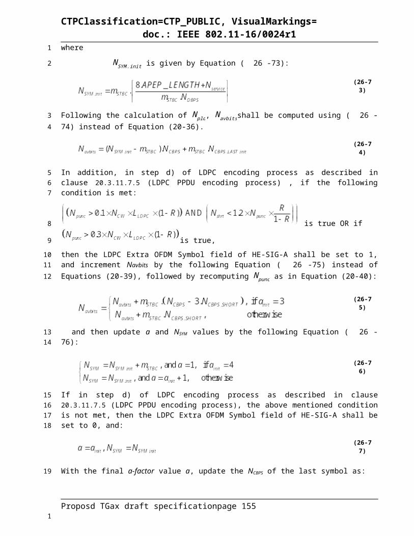
CTPClassification=CTP_PUBLIC, VisualMarkings=doc.: IEEE 802.11-16/0024r1
0.8 usec GI
1.6 usec GI
3.2 usec GI
0 1 1/4 1 980 245 1 18.0 17.0 15.30 0 1/2 1 980 490 1 36.0 34.0 30.61 1 1/4 2 1960 490 1 36.0 34.0 30.61 0 1/2 2 1960 980 1 72.1 68.1 61.32 N/A 3/4 2 1960 1,470 1 108.1 102.1 91.93 1 1/4 4 3920 980 1 72.1 68.1 61.33 0 1/2 4 3920 1,960 1 144.1 136.1 122.54 1 3/8 4 3920 1,470 1 108.1 102.1 91.94 0 3/4 4 3920 2,940 1 216.2 204.2 183.85 2/3 6 5880 3,920 1 288.2 272.2 245.06 3/4 6 5880 4,410 1 324.3 306.3 275.67 5/6 6 5880 4,900 1 360.3 340.3 306.38 3/4 8 7840 5,880 1 432.4 408.3 367.59 5/6 8 7840 6,533 1 480.4 453.7 408.3
10 3/4 10 9800 7,350 1 540.4 510.4 459.411 5/6 10 9800 8,166 1 600.4 567.1 510.4
N CBPS N DBPS N ESHE-MCS
IndexDCM
Data rate (Mb/s)
BPSK
980 16
64-QAM
256-QAM
1024-QAM
Modulation R N BPSCS
QPSK
16-QAM
N SD N SP
N/A
Table 26-81 HE-MCSs for TBD mandatory/optional 996-tone RU and mandatory non-OFDMA 80MHz, NSS = 2
0.8 usec GI
1.6 usec GI
3.2 usec GI
0 1 1/4 1 1960 490 1 36.0 34.0 30.60 0 1/2 1 1960 980 1 72.1 68.1 61.31 1 1/4 2 3920 980 1 72.1 68.1 61.31 0 1/2 2 3920 1,960 1 144.1 136.1 122.52 N/A 3/4 2 3920 2,940 1 216.2 204.2 183.83 1 1/4 4 7840 1,960 1 144.1 136.1 122.53 0 1/2 4 7840 3,920 1 288.2 272.2 245.04 1 3/8 4 7840 2,940 1 216.2 204.2 183.84 0 3/4 4 7840 5,880 1 432.4 408.3 367.55 2/3 6 11760 7,840 1 576.5 544.4 490.06 3/4 6 11760 8,820 1 648.5 612.5 551.37 5/6 6 11760 9,800 1 720.6 680.6 612.58 3/4 8 15680 11,760 1 864.7 816.7 735.09 5/6 8 15680 13,066 1 960.7 907.4 816.6
10 3/4 10 19600 14,700 1 1,080.9 1,020.8 918.811 5/6 10 19600 16,333 1 1,201.0 1,134.2 1,020.8
BPSK
980 16
64-QAM
256-QAM
1024-QAM
HE-MCS Index
N SD N SP N CBPS N DBPS N ES
Data rate (Mb/s)Modulation R N BPSCSDCM
QPSK
16-QAM
N/A
Table 26-82 HE-MCSs for TBD mandatory/optional 996-tone RU and mandatory non-OFDMA 80MHz, NSS = 3
Proposd TGax draft specification page 155
1
2
3
4
1

CTPClassification=CTP_PUBLIC, VisualMarkings=doc.: IEEE 802.11-16/0024r1
0.8 usec GI
1.6 usec GI
3.2 usec GI
0 1 1/4 1 2940 735 1 54.0 51.0 45.90 0 1/2 1 2940 1,470 1 108.1 102.1 91.91 1 1/4 2 5880 1,470 1 108.1 102.1 91.91 0 1/2 2 5880 2,940 1 216.2 204.2 183.82 N/A 3/4 2 5880 4,410 1 324.3 306.3 275.63 1 1/4 4 11760 2,940 1 216.2 204.2 183.83 0 1/2 4 11760 5,880 1 432.4 408.3 367.54 1 3/8 4 11760 4,410 1 324.3 306.3 275.64 0 3/4 4 11760 8,820 1 648.5 612.5 551.35 2/3 6 17640 11,760 1 864.7 816.7 735.06 3/4 6 17640 13,230 1 972.8 918.8 826.97 5/6 6 17640 14,700 1 1,080.9 1,020.8 918.88 3/4 8 23520 17,640 1 1,297.1 1,225.0 1,102.59 5/6 8 23520 19,600 1 1,441.2 1,361.1 1,225.0
10 3/4 10 29400 22,050 1 1,621.3 1,531.3 1,378.111 5/6 10 29400 24,500 1 1,801.5 1,701.4 1,531.3
HE-MCS Index
Modulation R N BPSCS N SD N CBPS N DBPS N ES
Data rate (Mb/s)
BPSK
980 16
64-QAM
N SP
256-QAM
1024-QAM
DCM
QPSK
16-QAM
N/A
Table 26-83 HE-MCSs for TBD mandatory/optional 996-tone RU and mandatory non-OFDMA 80MHz, NSS = 4
0.8 usec GI
1.6 usec GI
3.2 usec GI
0 1 1/4 1 3920 980 1 72.1 68.1 61.30 0 1/2 1 3920 1,960 1 144.1 136.1 122.51 1 1/4 2 7840 1,960 1 144.1 136.1 122.51 0 1/2 2 7840 3,920 1 288.2 272.2 245.02 N/A 3/4 2 7840 5,880 1 432.4 408.3 367.53 1 1/4 4 15680 3,920 1 288.2 272.2 245.03 0 1/2 4 15680 7,840 1 576.5 544.4 490.04 1 3/8 4 15680 5,880 1 432.4 408.3 367.54 0 3/4 4 15680 11,760 1 864.7 816.7 735.05 2/3 6 23520 15,680 1 1,152.9 1,088.9 980.06 3/4 6 23520 17,640 1 1,297.1 1,225.0 1,102.57 5/6 6 23520 19,600 1 1,441.2 1,361.1 1,225.08 3/4 8 31360 23,520 1 1,729.4 1,633.3 1,470.09 5/6 8 31360 26,133 1 1,921.5 1,814.8 1,633.3
10 3/4 10 39200 29,400 1 2,161.8 2,041.7 1,837.511 5/6 10 39200 32,666 1 2,401.9 2,268.5 2,041.6
16
N SD N SP N CBPS N DBPS N ES
Data rate (Mb/s)HE-MCS
IndexModulation R N BPSCSDCM
N/A
980
BPSK
64-QAM
256-QAM
1024-QAM
QPSK
16-QAM
Table 26-84 HE-MCSs for TBD mandatory/optional 996-tone RU and mandatory non-OFDMA 80MHz, NSS = 5
Proposd TGax draft specification page 156
1
2
3
4
5
1

CTPClassification=CTP_PUBLIC, VisualMarkings=doc.: IEEE 802.11-16/0024r1
0.8 usec GI
1.6 usec GI
3.2 usec GI
0 1 1/4 1 4900 1,225 1 90.1 85.1 76.60 0 1/2 1 4900 2,450 1 180.1 170.1 153.11 1 1/4 2 9800 2,450 1 180.1 170.1 153.11 0 1/2 2 9800 4,900 1 360.3 340.3 306.32 N/A 3/4 2 9800 7,350 1 540.4 510.4 459.43 1 1/4 4 19600 4,900 1 360.3 340.3 306.33 0 1/2 4 19600 9,800 1 720.6 680.6 612.54 1 3/8 4 19600 7,350 1 540.4 510.4 459.44 0 3/4 4 19600 14,700 1 1,080.9 1,020.8 918.85 2/3 6 29400 19,600 1 1,441.2 1,361.1 1,225.06 3/4 6 29400 22,050 1 1,621.3 1,531.3 1,378.17 5/6 6 29400 24,500 1 1,801.5 1,701.4 1,531.38 3/4 8 39200 29,400 1 2,161.8 2,041.7 1,837.59 5/6 8 39200 32,666 1 2,401.9 2,268.5 2,041.6
10 3/4 10 49000 36,750 1 2,702.2 2,552.1 2,296.911 5/6 10 49000 40,833 1 3,002.4 2,835.6 2,552.1
HE-MCS Index
Modulation R N BPSCS N SDDCM N CBPS N DBPS N ES
Data rate (Mb/s)
BPSK
980 16
64-QAM
QPSK
16-QAM
N SP
256-QAM
1024-QAM
N/A
Table 26-85 HE-MCSs for TBD mandatory/optional 996-tone RU and mandatory non-OFDMA 80MHz, NSS = 6
0.8 usec GI
1.6 usec GI
3.2 usec GI
0 1 1/4 1 5880 1,470 1 108.1 102.1 91.90 0 1/2 1 5880 2,940 1 216.2 204.2 183.81 1 1/4 2 11760 2,940 1 216.2 204.2 183.81 0 1/2 2 11760 5,880 1 432.4 408.3 367.52 N/A 3/4 2 11760 8,820 1 648.5 612.5 551.33 1 1/4 4 23520 5,880 1 432.4 408.3 367.53 0 1/2 4 23520 11,760 1 864.7 816.7 735.04 1 3/8 4 23520 8,820 1 648.5 612.5 551.34 0 3/4 4 23520 17,640 1 1,297.1 1,225.0 1,102.55 2/3 6 35280 23,520 1 1,729.4 1,633.3 1,470.06 3/4 6 35280 26,460 1 1,945.6 1,837.5 1,653.87 5/6 6 35280 29,400 1 2,161.8 2,041.7 1,837.58 3/4 8 47040 35,280 1 2,594.1 2,450.0 2,205.09 5/6 8 47040 39,200 1 2,882.4 2,722.2 2,450.0
10 3/4 10 58800 44,100 1 3,242.6 3,062.5 2,756.311 5/6 10 58800 49,000 1 3,602.9 3,402.8 3,062.5
N SD N SP N CBPS N DBPS N ES
Data rate (Mb/s)HE-MCS
IndexModulation R N BPSCSDCM
BPSK
980 16
64-QAM
256-QAM
1024-QAM
QPSK
16-QAM
N/A
Table 26-86 HE-MCSs for TBD mandatory/optional 996-tone RU and mandatory non-OFDMA 80MHz, NSS = 7
Proposd TGax draft specification page 157
1
2
3
4
1

CTPClassification=CTP_PUBLIC, VisualMarkings=doc.: IEEE 802.11-16/0024r1
0.8 usec GI
1.6 usec GI
3.2 usec GI
0 1 1/4 1 6860 1,715 1 126.1 119.1 107.20 0 1/2 1 6860 3,430 1 252.2 238.2 214.41 1 1/4 2 13720 3,430 1 252.2 238.2 214.41 0 1/2 2 13720 6,860 1 504.4 476.4 428.82 N/A 3/4 2 13720 10,290 1 756.6 714.6 643.13 1 1/4 4 27440 6,860 1 504.4 476.4 428.83 0 1/2 4 27440 13,720 1 1,008.8 952.8 857.54 1 3/8 4 27440 10,290 1 756.6 714.6 643.14 0 3/4 4 27440 20,580 1 1,513.2 1,429.2 1,286.35 2/3 6 41160 27,440 1 2,017.6 1,905.6 1,715.06 3/4 6 41160 30,870 1 2,269.9 2,143.8 1,929.47 5/6 6 41160 34,300 1 2,522.1 2,381.9 2,143.88 3/4 8 54880 41,160 1 3,026.5 2,858.3 2,572.59 5/6 8 54880 45,733 1 3,362.7 3,175.9 2,858.3
10 3/4 10 68600 51,450 1 3,783.1 3,572.9 3,215.611 5/6 10 68600 57,166 1 4,203.4 3,969.9 3,572.9
HE-MCS Index
Modulation R N BPSCS N SD N SPDCM N CBPS N DBPS N ES
Data rate (Mb/s)
BPSK
980 16
64-QAM
QPSK
16-QAM
256-QAM
1024-QAM
N/A
Table 26-87 HE-MCSs for TBD mandatory/optional 996-tone RU and mandatory non-OFDMA 80MHz, NSS = 8
0.8 usec GI
1.6 usec GI
3.2 usec GI
0 1 1/4 1 7840 1,960 1 144.1 136.1 122.50 0 1/2 1 7840 3,920 1 288.2 272.2 245.01 1 1/4 2 15680 3,920 1 288.2 272.2 245.01 0 1/2 2 15680 7,840 1 576.5 544.4 490.02 N/A 3/4 2 15680 11,760 1 864.7 816.7 735.03 1 1/4 4 31360 7,840 1 576.5 544.4 490.03 0 1/2 4 31360 15,680 1 1,152.9 1,088.9 980.04 1 3/8 4 31360 11,760 1 864.7 816.7 735.04 0 3/4 4 31360 23,520 1 1,729.4 1,633.3 1,470.05 2/3 6 47040 31,360 1 2,305.9 2,177.8 1,960.06 3/4 6 47040 35,280 1 2,594.1 2,450.0 2,205.07 5/6 6 47040 39,200 1 2,882.4 2,722.2 2,450.08 3/4 8 62720 47,040 1 3,458.8 3,266.7 2,940.09 5/6 8 62720 52,266 1 3,843.1 3,629.6 3,266.6
10 3/4 10 78400 58,800 1 4,323.5 4,083.3 3,675.011 5/6 10 78400 65,333 1 4,803.9 4,537.0 4,083.3
N CBPS N DBPS N ES
Data rate (Mb/s)HE-MCS
IndexModulation R N BPSCSDCM
980 16
64-QAM
256-QAM
1024-QAM
N SD N SP
QPSK
16-QAM
N/A
BPSK
Table 26-88 HE-MCSs for optional non-OFDMA 160/80+80MHz, NSS = 1
Proposd TGax draft specification page 158
1
2
3
4
5
1

CTPClassification=CTP_PUBLIC, VisualMarkings=doc.: IEEE 802.11-16/0024r1
0.8 usec GI
1.6 usec GI
3.2 usec GI
0 1 1/4 1 1960 490 1 36.0 34.0 30.60 0 1/2 1 1960 980 1 72.1 68.1 61.31 1 1/4 2 3920 980 1 72.1 68.1 61.31 0 1/2 2 3920 1,960 1 144.1 136.1 122.52 N/A 3/4 2 3920 2,940 1 216.2 204.2 183.83 1 1/4 4 7840 1,960 1 144.1 136.1 122.53 0 1/2 4 7840 3,920 1 288.2 272.2 245.04 1 3/8 4 7840 2,940 1 216.2 204.2 183.84 0 3/4 4 7840 5,880 1 432.4 408.3 367.55 2/3 6 11760 7,840 1 576.5 544.4 490.06 3/4 6 11760 8,820 1 648.5 612.5 551.37 5/6 6 11760 9,800 1 720.6 680.6 612.58 3/4 8 15680 11,760 1 864.7 816.7 735.09 5/6 8 15680 13,066 1 960.7 907.4 816.610 3/4 10 19600 14,700 1 1,080.9 1,020.8 918.811 5/6 10 19600 16,333 1 1,201.0 1,134.2 1,020.8
256-QAM
1024-QAM
N CBPS N DBPS N ES
Data rate (Mb/s)
BPSK
1960 32
64-QAM
HE-MCS Index
Modulation R N BPSCS N SD N SPDCM
QPSK
16-QAM
N/A
Table 26-89 HE-MCSs for optional non-OFDMA 160/80+80MHz, NSS = 2
0.8 usec GI
1.6 usec GI
3.2 usec GI
0 1 1/4 1 3920 980 1 72.1 68.1 61.30 0 1/2 1 3920 1,960 1 144.1 136.1 122.51 1 1/4 2 7840 1,960 1 144.1 136.1 122.51 0 1/2 2 7840 3,920 1 288.2 272.2 245.02 N/A 3/4 2 7840 5,880 1 432.4 408.3 367.53 1 1/4 4 15680 3,920 1 288.2 272.2 245.03 0 1/2 4 15680 7,840 1 576.5 544.4 490.04 1 3/8 4 15680 5,880 1 432.4 408.3 367.54 0 3/4 4 15680 11,760 1 864.7 816.7 735.05 2/3 6 23520 15,680 1 1,152.9 1,088.9 980.06 3/4 6 23520 17,640 1 1,297.1 1,225.0 1,102.57 5/6 6 23520 19,600 1 1,441.2 1,361.1 1,225.08 3/4 8 31360 23,520 1 1,729.4 1,633.3 1,470.09 5/6 8 31360 26,133 1 1,921.5 1,814.8 1,633.310 3/4 10 39200 29,400 1 2,161.8 2,041.7 1,837.511 5/6 10 39200 32,666 1 2,401.9 2,268.5 2,041.6
N ES
Data rate (Mb/s)HE-MCS
IndexModulation R N BPSCS
1960 32
64-QAM
256-QAM
1024-QAM
N SD N SP N CBPS N DBPS
N/A
DCM
QPSK
16-QAM
BPSK
Table 26-90 HE-MCSs for optional non-OFDMA 160/80+80MHz, NSS = 3
Proposd TGax draft specification page 159
1
2
3
4
5
1

CTPClassification=CTP_PUBLIC, VisualMarkings=doc.: IEEE 802.11-16/0024r1
0.8 usec GI
1.6 usec GI
3.2 usec GI
0 1 1/4 1 5880 1,470 1 108.1 102.1 91.90 0 1/2 1 5880 2,940 1 216.2 204.2 183.81 1 1/4 2 11760 2,940 1 216.2 204.2 183.81 0 1/2 2 11760 5,880 1 432.4 408.3 367.52 N/A 3/4 2 11760 8,820 1 648.5 612.5 551.33 1 1/4 4 23520 5,880 1 432.4 408.3 367.53 0 1/2 4 23520 11,760 1 864.7 816.7 735.04 1 3/8 4 23520 8,820 1 648.5 612.5 551.34 0 3/4 4 23520 17,640 1 1,297.1 1,225.0 1,102.55 2/3 6 35280 23,520 1 1,729.4 1,633.3 1,470.06 3/4 6 35280 26,460 1 1,945.6 1,837.5 1,653.87 5/6 6 35280 29,400 1 2,161.8 2,041.7 1,837.58 3/4 8 47040 35,280 1 2,594.1 2,450.0 2,205.09 5/6 8 47040 39,200 1 2,882.4 2,722.2 2,450.010 3/4 10 58800 44,100 1 3,242.6 3,062.5 2,756.311 5/6 10 58800 49,000 1 3,602.9 3,402.8 3,062.5
N CBPS N DBPS N ES
Data rate (Mb/s)
BPSK
1960 32
64-QAM
HE-MCS Index
Modulation R N BPSCS N SD N SP
256-QAM
1024-QAM
DCM
QPSK
16-QAM
N/A
Table 26-91 HE-MCSs for optional non-OFDMA 160/80+80MHz, NSS = 4
0.8 usec GI
1.6 usec GI
3.2 usec GI
0 1 1/4 1 7840 1,960 1 144.1 136.1 122.50 0 1/2 1 7840 3,920 1 288.2 272.2 245.01 1 1/4 2 15680 3,920 1 288.2 272.2 245.01 0 1/2 2 15680 7,840 1 576.5 544.4 490.02 N/A 3/4 2 15680 11,760 1 864.7 816.7 735.03 1 1/4 4 31360 7,840 1 576.5 544.4 490.03 0 1/2 4 31360 15,680 1 1,152.9 1,088.9 980.04 1 3/8 4 31360 11,760 1 864.7 816.7 735.04 0 3/4 4 31360 23,520 1 1,729.4 1,633.3 1,470.05 2/3 6 47040 31,360 1 2,305.9 2,177.8 1,960.06 3/4 6 47040 35,280 1 2,594.1 2,450.0 2,205.07 5/6 6 47040 39,200 1 2,882.4 2,722.2 2,450.08 3/4 8 62720 47,040 1 3,458.8 3,266.7 2,940.09 5/6 8 62720 52,266 1 3,843.1 3,629.6 3,266.610 3/4 10 78400 58,800 1 4,323.5 4,083.3 3,675.011 5/6 10 78400 65,333 1 4,803.9 4,537.0 4,083.3
N CBPS N DBPS N ES
Data rate (Mb/s)HE-MCS
IndexModulation R N BPSCS
BPSK
1960 32
64-QAM
256-QAM
1024-QAM
QPSK
16-QAM
N SD N SPDCM
N/A
Table 26-92 HE-MCSs for optional non-OFDMA 160/80+80MHz, NSS = 5
Proposd TGax draft specification page 160
1
2
3
4
5
1
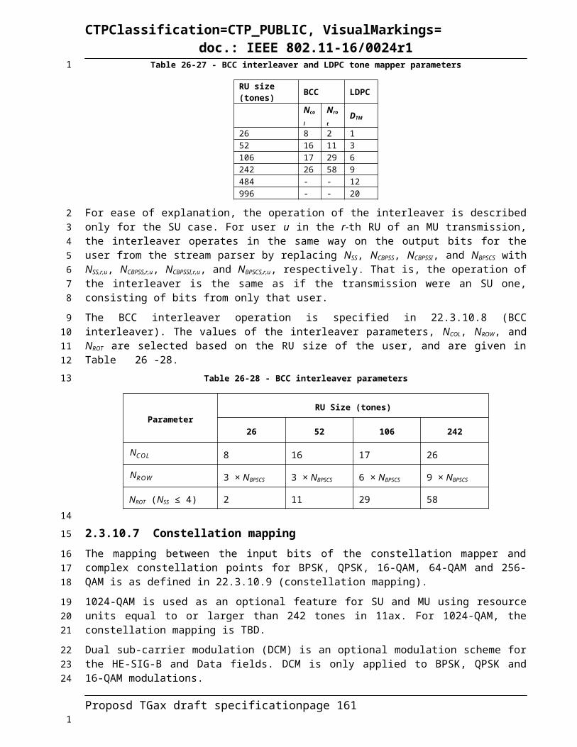
CTPClassification=CTP_PUBLIC, VisualMarkings=doc.: IEEE 802.11-16/0024r1
0.8 usec GI
1.6 usec GI
3.2 usec GI
0 1 1/4 1 9800 2,450 1 180.1 170.1 153.10 0 1/2 1 9800 4,900 1 360.3 340.3 306.31 1 1/4 2 19600 4,900 1 360.3 340.3 306.31 0 1/2 2 19600 9,800 1 720.6 680.6 612.52 N/A 3/4 2 19600 14,700 1 1,080.9 1,020.8 918.83 1 1/4 4 39200 9,800 1 720.6 680.6 612.53 0 1/2 4 39200 19,600 1 1,441.2 1,361.1 1,225.04 1 3/8 4 39200 14,700 1 1,080.9 1,020.8 918.84 0 3/4 4 39200 29,400 1 2,161.8 2,041.7 1,837.55 2/3 6 58800 39,200 1 2,882.4 2,722.2 2,450.06 3/4 6 58800 44,100 1 3,242.6 3,062.5 2,756.37 5/6 6 58800 49,000 1 3,602.9 3,402.8 3,062.58 3/4 8 78400 58,800 1 4,323.5 4,083.3 3,675.09 5/6 8 78400 65,333 1 4,803.9 4,537.0 4,083.310 3/4 10 98000 73,500 1 5,404.4 5,104.2 4,593.811 5/6 10 98000 81,666 1 6,004.9 5,671.3 5,104.1
N CBPS N DBPS N ES
Data rate (Mb/s)
BPSK
1960 32
64-QAM
HE-MCS Index
Modulation R N BPSCS N SD N SP
256-QAM
1024-QAM
DCM
QPSK
16-QAM
N/A
Table 26-93 HE-MCSs for optional non-OFDMA 160/80+80MHz, NSS = 6
0.8 usec GI
1.6 usec GI
3.2 usec GI
0 1 1/4 1 11760 2,940 1 216.2 204.2 183.80 0 1/2 1 11760 5,880 1 432.4 408.3 367.51 1 1/4 2 23520 5,880 1 432.4 408.3 367.51 0 1/2 2 23520 11,760 1 864.7 816.7 735.02 N/A 3/4 2 23520 17,640 1 1,297.1 1,225.0 1,102.53 1 1/4 4 47040 11,760 1 864.7 816.7 735.03 0 1/2 4 47040 23,520 1 1,729.4 1,633.3 1,470.04 1 3/8 4 47040 17,640 1 1,297.1 1,225.0 1,102.54 0 3/4 4 47040 35,280 1 2,594.1 2,450.0 2,205.05 2/3 6 70560 47,040 1 3,458.8 3,266.7 2,940.06 3/4 6 70560 52,920 1 3,891.2 3,675.0 3,307.57 5/6 6 70560 58,800 1 4,323.5 4,083.3 3,675.08 3/4 8 94080 70,560 1 5,188.2 4,900.0 4,410.09 5/6 8 94080 78,400 1 5,764.7 5,444.4 4,900.010 3/4 10 117600 88,200 1 6,485.3 6,125.0 5,512.511 5/6 10 117600 98,000 1 7,205.9 6,805.6 6,125.0
N CBPS N DBPS N ES
Data rate (Mb/s)HE-MCS
IndexModulation R N BPSCS
1960 32
64-QAM
256-QAM
1024-QAM
QPSK
16-QAM
N SD N SP
N/A
DCM
BPSK
Table 26-94 HE-MCSs for optional non-OFDMA 160/80+80MHz, NSS = 7
Proposd TGax draft specification page 161
1
2
3
4
5
1

CTPClassification=CTP_PUBLIC, VisualMarkings=doc.: IEEE 802.11-16/0024r1
0.8 usec GI
1.6 usec GI
3.2 usec GI
0 1 1/4 1 13720 3,430 1 252.2 238.2 214.40 0 1/2 1 13720 6,860 1 504.4 476.4 428.81 1 1/4 2 27440 6,860 1 504.4 476.4 428.81 0 1/2 2 27440 13,720 1 1,008.8 952.8 857.52 N/A 3/4 2 27440 20,580 1 1,513.2 1,429.2 1,286.33 1 1/4 4 54880 13,720 1 1,008.8 952.8 857.53 0 1/2 4 54880 27,440 1 2,017.6 1,905.6 1,715.04 1 3/8 4 54880 20,580 1 1,513.2 1,429.2 1,286.34 0 3/4 4 54880 41,160 1 3,026.5 2,858.3 2,572.55 2/3 6 82320 54,880 1 4,035.3 3,811.1 3,430.06 3/4 6 82320 61,740 1 4,539.7 4,287.5 3,858.87 5/6 6 82320 68,600 1 5,044.1 4,763.9 4,287.58 3/4 8 109760 82,320 1 6,052.9 5,716.7 5,145.09 5/6 8 109760 91,466 1 6,725.4 6,351.8 5,716.610 3/4 10 137200 102,900 1 7,566.2 7,145.8 6,431.311 5/6 10 137200 114,333 1 8,406.8 7,939.8 7,145.8
N CBPS N DBPS N ES
Data rate (Mb/s)
BPSK
1960 32
64-QAM
HE-MCS Index
Modulation R N BPSCS N SD N SP
256-QAM
1024-QAM
DCM
QPSK
16-QAM
N/A
Table 26-95 HE-MCSs for optional non-OFDMA 160/80+80MHz, NSS = 8
0.8 usec GI
1.6 usec GI
3.2 usec GI
0 1 1/4 1 15680 3,920 1 288.2 272.2 245.00 0 1/2 1 15680 7,840 1 576.5 544.4 490.01 1 1/4 2 31360 7,840 1 576.5 544.4 490.01 0 1/2 2 31360 15,680 1 1,152.9 1,088.9 980.02 N/A 3/4 2 31360 23,520 1 1,729.4 1,633.3 1,470.03 1 1/4 4 62720 15,680 1 1,152.9 1,088.9 980.03 0 1/2 4 62720 31,360 1 2,305.9 2,177.8 1,960.04 1 3/8 4 62720 23,520 1 1,729.4 1,633.3 1,470.04 0 3/4 4 62720 47,040 1 3,458.8 3,266.7 2,940.05 2/3 6 94080 62,720 1 4,611.8 4,355.6 3,920.06 3/4 6 94080 70,560 1 5,188.2 4,900.0 4,410.07 5/6 6 94080 78,400 1 5,764.7 5,444.4 4,900.08 3/4 8 125440 94,080 1 6,917.6 6,533.3 5,880.09 5/6 8 125440 104,533 1 7,686.3 7,259.2 6,533.310 3/4 10 156800 117,600 1 8,647.1 8,166.7 7,350.011 5/6 10 156800 130,666 1 9,607.8 9,074.0 8,166.6
N CBPS N DBPS N ES
Data rate (Mb/s)HE-MCS
IndexModulation R N BPSCS
1960 32
64-QAM
256-QAM
1024-QAM
QPSK
16-QAM
N SD N SP
N/A
DCM
BPSK
Proposd TGax draft specification page 162
1
2
345
1

CTPClassification=CTP_PUBLIC, VisualMarkings=doc.: IEEE 802.11-16/0024r1
Annex C
26.6 C.3 MIB Detail
Insert the following (after getting some sucker to validate MIB compilation, etc.):
dot11PPEThresholdsRequired OBJECT-TYPESYNTAX TruthValueMAX-ACCESS read-onlySTATUS currentDESCRIPTION
"This is a capability variable.Its value is determined by device capabilities.This attribute, when true, indicates that Post-FEC Padding and Packet Extension Thresholds exist and are provided in the dot11PPEThresholdsTable MIB."
DEFVAL { false }::= { dot11StationConfigEntry <ANA> }
**********************************************************************-- **********************************************************************-- * dot11PPEThresholdsMappings TABLE-- **********************************************************************dot11PPEThresholdsMappingsTable OBJECT-TYPE
SYNTAX SEQUENCE OF Dot11PPEThresholdsMappingsEntryMAX-ACCESS not-accessibleSTATUS currentDESCRIPTION
"Conceptual table for PPE Thresholds Mappings. The MIB supports the ability to share separate PPE Thresholds for each NSS/RU pair. The Thresholds Mappings Table contains one entry for each NSS/RU pair and contains two fields for each entry: PPET8 and PPET16. The PPE Thresholds mappings are logically WRITE-ONLY. Attempts to read the entries in this table return unsuccessful status and values of null or 0. The default value for all PPET8 fields is NONE."
REFERENCE "IEEE Std 802.11-<year>, 9.47 (HE Post-FEC Padding and Packet Extension)"
::= { dot11smt 4 }
dot11PPEThresholdsMappingsEntry OBJECT-TYPE
Proposd TGax draft specification page 163
1
23
4
56789
10111213141516171819202122232425262728293031323334353637383940414243444546
1

CTPClassification=CTP_PUBLIC, VisualMarkings=doc.: IEEE 802.11-16/0024r1
SYNTAX Dot11PPEThresholdsMappingsEntryMAX-ACCESS not-accessibleSTATUS currentDESCRIPTION
"An Entry (conceptual row) in the PPE Thresholds Mappings Table. ifIndex - Each IEEE Std 802.11 interface is represented by an ifEntry. Interface tables in this MIB module are indexed by ifIndex."
INDEX { ifIndex, dot11PPEThresholdsMappingIndex }::= { dot11PPEThresholdsMappingsTable 1 }
Dot11PPEThresholdsMappingsEntry ::=SEQUENCE {
dot11PPEThresholdsMappingIndex Unsigned32, dot11PPEThresholdsMappingNSS Integer,dot11PPEThresholdsMappingRUIndex Integer,dot11PPEThresholdsMappingPPET8 Integer, dot11PPEThresholdsMappingPPET16 Integer, dot11PPEThresholdsMappingStatus RowStatus }
dot11PPEThresholdsMappingIndex OBJECT-TYPESYNTAX Unsigned32MAX-ACCESS not-accessibleSTATUS currentDESCRIPTION
"The auxiliary variable used to identify instances of the columnar objects in the PPE Thresholds Mappings Table."
::= { dot11PPEThresholdsMappingsEntry 1 }
dot11PPEThresholdsMappingNSS OBJECT-TYPESYNTAX IntegerMAX-ACCESS read-createSTATUS currentDESCRIPTION
"The NSS value portion of the NSS/RU pair for which the values from this Thresholds mapping entry are to be used."
::= { dot11PPEThresholdsMappingsEntry 2 }
dot11PPEThresholdsMappingRUIndex OBJECT-TYPESYNTAX IntegerMAX-ACCESS read-createSTATUS currentDESCRIPTION
"The index of the RU value portion of the NSS/RU pair for which the values from this Thresholds mapping entry are to be used. The index values map to an RU as follows: RU Index of 0 is 996 tones, 1 is 448 tones, 2 is TBD tones, 3 is reserved."
Proposd TGax draft specification page 164
123456789
1011121314151617181920212223242526272829303132333435363738394041424344454647484950
1

CTPClassification=CTP_PUBLIC, VisualMarkings=doc.: IEEE 802.11-16/0024r1
::= { dot11PPEThresholdsMappingsEntry 3 }
dot11PPEThresholdsMappingPPET8 OBJECT-TYPESYNTAX TruthValueMAX-ACCESS read-createSTATUS currentDESCRIPTION
"An index that determines a constellation value at or above which a Post FEC Padding and Packet Extension value of at least 8 us is required for the given NSS/RU pair corresponding to the row of the entry. The index values are mapped as follows: 0 is BPSK, 1 is QPSK, 2 is 16QAM, 3 is 64QAM, 4 is 256QAM, 5 is 1024QAM, 6 is reserved, 7 is the special value of NONE."
::= { dot11PPEThresholdsMappingsEntry 4 }
dot11PPEThresholdsMappingPPET16 OBJECT-TYPESYNTAX TruthValueMAX-ACCESS read-createSTATUS currentDESCRIPTION
"An index that determines a constellation value at or above which a Post FEC Padding and Packet Extension value of 16 us is required for the given NSS/RU pair corresponding to the row of the entry. The index values are mapped as follows: 0 is BPSK, 1 is QPSK, 2 is 16QAM, 3 is 64QAM, 4 is 256QAM, 5 is 1024QAM, 6 is reserved, 7 is the special value of NONE."
::= { dot11PPEThresholdsMappingsEntry 5 }
dot11PPEThresholdsMappingStatus OBJECT-TYPESYNTAX RowStatusMAX-ACCESS read-createSTATUS currentDESCRIPTION
"The status column used for creating, modifying, and deleting instances of the columnar objects in the PPE Thresholds mapping Table."
DEFVAL { active }::= { dot11PPEThresholdsMappingsEntry 6 }
**********************************************************************-- * End of dot11PPEThresholdsMappings TABLE-- **********************************************************************
Proposd TGax draft specification page 165
123456789
101112131415161718192021222324252627282930313233343536373839404142434445464748
1