
Doc 00 Rev D 2019-16-Oct
20
Doc 00-HTX03 Rev D 2019-16-Oct
Transcript of Doc 00 Rev D 2019-16-Oct

Doc 00-HTX03 Rev D 2019-16-Oct

Contents
Shipping Preparation, Storage & Handling 4 Transport 4
Storage 4
Handling 4
Pre-Installation Preparation 4 Survey the Installation 4
Inspect the Thermocouple and Accessories 5
Inspect the Nozzle 6
Resolving Dimensional Problems 7
Installing the Thermocouple 8 Vertical Installation 8
Non-Vertical Installation 11
Non-Vertical Installation - Using the HMB Mounting Bars 12
Wiring 13
Purge Gas Connection 14
Purge/Element Well Integrity Test 15
Technical Operation and Maintenance 15 Using Multiple Thermocouples within the HTX 15
Pre-Commissioning/Commissioning Procedure (Startup) 15
Shutdown 15
Operation 15
Maintenance 16
Troubleshooting 16
Specifications 17
A brief video presentation of the steps of the
complete HTP/HTX installation may be found at
www.claustemp.com/
INSTALLATION GUIDE
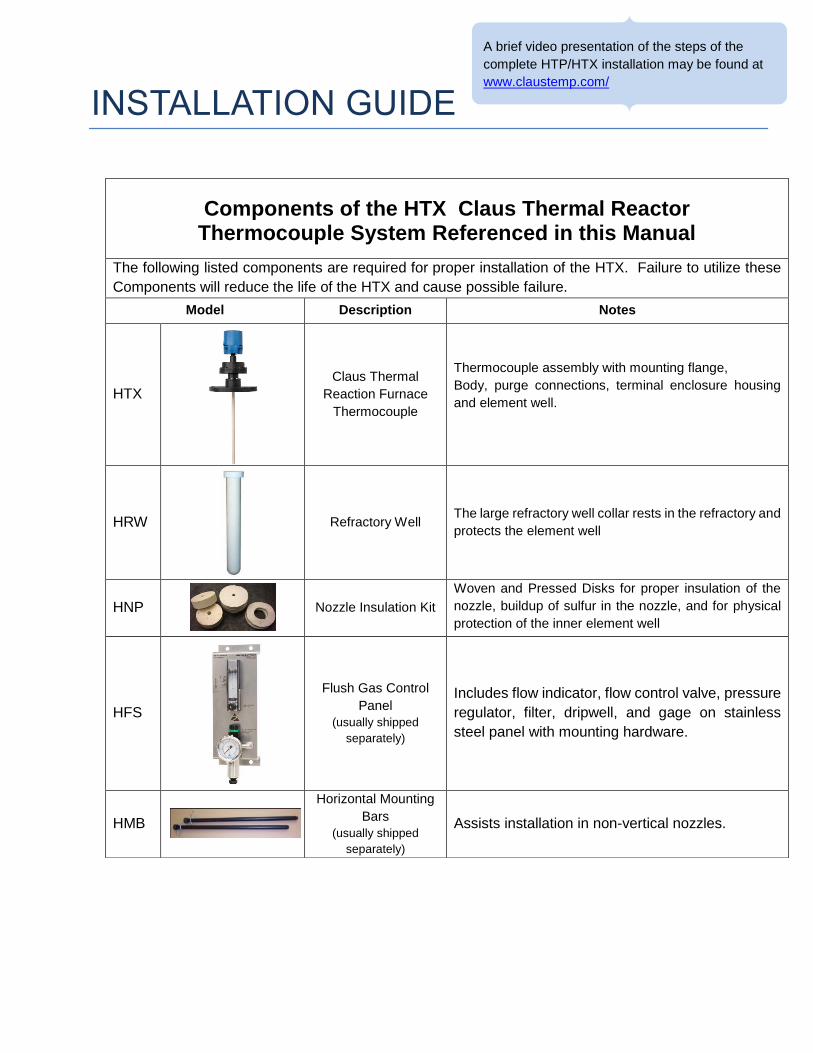
Components of the HTX Claus Thermal Reactor Thermocouple System Referenced in this Manual
The following listed components are required for proper installation of the HTX. Failure to utilize these
Components will reduce the life of the HTX and cause possible failure.
Model Description Notes
HTX
Claus Thermal
Reaction Furnace
Thermocouple
Thermocouple assembly with mounting flange,
Body, purge connections, terminal enclosure housing
and element well.
HRW
Refractory Well The large refractory well collar rests in the refractory and
protects the element well
HNP
Nozzle Insulation Kit
Woven and Pressed Disks for proper insulation of the
nozzle, buildup of sulfur in the nozzle, and for physical
protection of the inner element well
HFS
Flush Gas Control
Panel
(usually shipped
separately)
Includes flow indicator, flow control valve, pressure
regulator, filter, dripwell, and gage on stainless
steel panel with mounting hardware.
HMB
Horizontal Mounting
Bars
(usually shipped
separately)
Assists installation in non-vertical nozzles.
Shipping Preparation, Storage & Handling
Transport
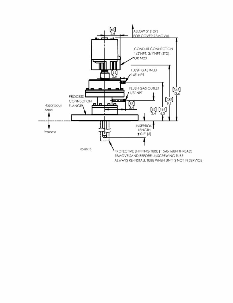
Care should be used in carrying, moving, and shipping the HTX thermocouple. A significant portion of the HTX is constructed of ceramic. Ceramics are very brittle at ambient temperature and can be damaged by mechanical shock. The unit is equipped with a sand-filled protective shipping tube when it leaves the factory. This tube and its sand packing should be left in place until the persons installing the unit have arrived at the installation site and are ready to insert the HTX and make up the flange. The shipping tube and shipping crate should be retained for re-shipment and storage of the HTX assembly.
Storage
Store equipment in a clean, dry place. It is recommended that the equipment remain packaged until ready for installation to prevent breakage or misplacing of components. When storing a unit or preparing it for shipment, the shipping tube should be reinstalled and filled with clean, fine #1 blasting sand.
Handling
Unit(s) are constructed with ceramic material that is susceptible to damage from rough handling. Unit(s) should only be handled with their protective shipping pipes in place, and, whenever possible transported to/from the installation site in their original shipping containers.
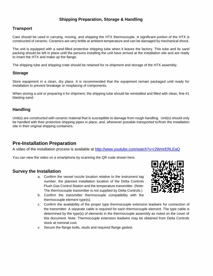
Pre-Installation Preparation A video of the installation process is available at http://www.youtube.com/watch?v=r2WmrERLEaQ
You can view the video on a smartphone by scanning the QR code shown here.
Survey the Installation a. Confirm the vessel nozzle location relative to the instrument tag
number, the planned installation location of the Delta Controls
Flush Gas Control Station and the temperature transmitter. (Note:
The thermocouple transmitter is not supplied by Delta Controls.)
b. Confirm the transmitter thermocouple compatibility with the
thermocouple element type(s).
c. Confirm the availability of the proper type thermocouple extension leadwire for connection of
the transmitter. A separate cable is required for each thermocouple element. The type cable is
determined by the type(s) of elements in the thermocouple assembly as noted on the cover of
this document. Note: Thermocouple extension leadwire may be obtained from Delta Controls
stock at nominal cost.
d. Secure the flange bolts, studs and required flange gasket.
Inspect the Thermocouple and Accessories
a. Open the carton and carefully remove the top layer of the packing materials. b. Visually inspect the HTX Assembly for damage. c. Visually inspect the large ceramic HRW Refractory Well for damage. Be very careful not to drop
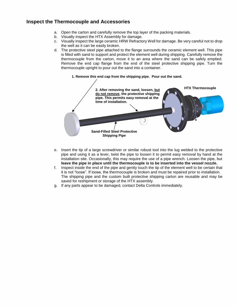
the well as it can be easily broken. d. The protective steel pipe attached to the flange surrounds the ceramic element well. This pipe
is filled with sand to support and protect the element well during shipping. Carefully remove the thermocouple from the carton, move it to an area where the sand can be safely emptied. Remove the end cap flange from the end of the steel protective shipping pipe. Turn the thermocouple upright to pour out the sand into a container.
e. Insert the tip of a large screwdriver or similar robust tool into the lug welded to the protective pipe and using it as a lever, twist the pipe to loosen it to permit easy removal by hand at the installation site. Occasionally, this may require the use of a pipe wrench. Loosen the pipe, but leave the pipe in place until the thermocouple is to be inserted into the vessel nozzle.
f. Inspect inside the end of the pipe and gently touch the tip of the element well to be certain that it is not “loose”. If loose, the thermocouple is broken and must be repaired prior to installation. The shipping pipe and the custom built protective shipping carton are reusable and may be saved for reshipment or storage of the HTX assembly.
g. If any parts appear to be damaged, contact Delta Controls immediately.
Sand-Filled Steel Protective Shipping Pipe
HTX Thermocouple 2. After removing the sand, loosen, but do not remove, the protective shipping pipe. This permits easy removal at the time of installation.
1. Remove this end cap from the shipping pipe. Pour out the sand.

Inspect the Nozzle
Because the “as-built” dimensions of the refractory and nozzle can (and often do) differ from the design specifications, it is important to verify these dimensions before installing the thermocouple. Installing a thermocouple that is not properly sized for the nozzle and refractory can result in breakage or inaccurate measurements.
Inspect the inside of the vessel nozzle. The inside
of the nozzle should be clean and free from debris and
welding slag. The hole cut through the vessel shell at
the base of the nozzle should be a minimum 3-1/2” (90
mm) diameter. The top refractory surface should be
even and free from extensive damage. The bored hole
through the refractory should be clean, 2.2” to 2.4” (56-
61mm) diameter, centered in the nozzle and in
perpendicular alignment relative to the nozzle flange
face. If the hole does not meet the above criteria, the
thermocouple can become broken shortly after start up
as refractory begins to shift.
Check the nozzle and refractory dimensions.
(Refer to the drawing on the cover of this document)
To ascertain Insertion Length “F”, lay a straight edge
across the flange face and with a measuring tape,
hook the inside surface (hot face) of the refractory
inside the vessel and measure up to the straight edge.
Confirm this dimension is the same as the length of
the thermocouple element well as measured from the
thermocouple flange to the tip of the well.
(If the thermocouple element well is too long, it will
contact the refractory well when it is inserted, causing
it to become broken. If the thermocouple is too short,
it may read erroneously low.
Measure the Refractory Thickness with a
measuring tape. Confirm that this distance matches
the length of the straight portion of the HRW Refractory
Well as shown.
(If the HRW well is too short, the thermocouple will
contact it during thermocouple insertion, causing it to
break. If the HRW well is too long, there is an
increased possibility of breakage due to thermal
shock)
If there is a discrepancy of more than
0.5in (12 mm) on the above
measurements, DO NOT install the
thermocouple until the discrepancy
is resolved. (see below)
Insertion
Length ”F” Insertion
Length ”F”
HRW Refractory Well
Refractory
Thickness
Refractory
Thickness
Note: The HRW Refractory Well is intended to
protrude approximately 1in (25 mm) beyond the
refractory hot face
Resolving Dimensional Problems
Carefully measure the nozzle and refractory dimensions and compare them to the dimensions on the front
cover of this manual. Dimensional discrepancies are commonly caused by the following conditions:
1. Nozzle inner diameter is not as specified – If the nozzle I.D. is too small, the hard insulating rings
will not fit. These rings can be cut down to size. This is best done in a lathe with a tapered arbor to
fit the center hole. Use a dust collector when cutting these rings to avoid breathing the dust.
2. Nozzle height is not as specified – If the nozzle is too tall, the thermocouple will not extend all the
way into the vessel and may report erroneously low temperatures. If the nozzle is too short, the
thermocouple may contact the bottom of the refractory well causing it to break. (See Note “4”,
below). Contact Delta Controls to arrange for a thermocouple correctly sized for the installation.
3. Incorrectly specified thermocouple dimensions – The design intent is for the thermocouple
element tip to be positioned even with the refractory hot face, and for the HRW Refractory Well to
extend approximately 1 inch (2.5 cm) past the refractory hot face. If these conditions are not met,
the result may be inaccurate measurement and/or breakage due to mechanical interference or
thermal shock. Contact Delta Controls to arrange for a thermocouple that is correctly sized for the
installation.
4. Refractory has entered the base of the nozzle – The top surface of the refractory should be even
with the inside surface of the vessel shell. If it is not, the HRW Refractory Well will not rest at the
proper position and may cause it to be broken when the thermocouple is inserted into the nozzle. If
there is refractory material inside the base of the nozzle, it must be removed to restore a flat surface
that is even with the inner surface of the vessel shell.
5. Refractory is not installed at the specified thickness – If the overall refractory is thicker than
specified, the thermocouple will not extend all the way into the vessel and may report erroneously
low temperatures. If the refractory is thinner than specified, the thermocouple will extend past the
refractory hot face. This could increase the possibility of breakage due to thermal shock. Contact
Delta Controls to arrange for a thermocouple that is correctly sized for the installation.
6. Refractory firebrick has separated from the insulating castable – It is not uncommon for the
firebrick to sag and form a gap between the firebrick and the castable or insulating brick. Often,
thermal expansion will cause this gap to close by itself when the furnace reaches operating
temperature. If this is the only cause of dimensional discrepancy, thermocouple installation may
proceed.
7. Refractory has separated from the vessel shell – This condition is not common, but it is possible
for a gap to appear between the insulating refractory and the vessel shell. The result is that the
thermocouple may not extend far enough into the vessel to reach the refractory hot face and may
report erroneously low temperatures. In general, this gap will not close up at operating
temperatures. The thermocouple must be re-sized to account for the gap. Contact Delta Controls to
arrange for a thermocouple that is correctly sized for the installation.
Installing the Thermocouple
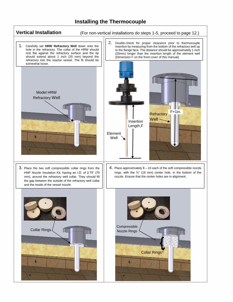
Vertical Installation (For non-vertical installations do steps 1-5, proceed to page 12.)
1. Carefully set HRW Refractory Well down onto the hole in the refractory. The collar of the HRW should rest flat against the refractory surface and the tip should extend about 1 inch (25 mm) beyond the refractory into the reactor vessel. The fit should be somewhat loose.
Model HRW
Refractory Well
F+1in.
Insertion Length,F
Element Well
Refractory
Well
3. Place the two soft compressible collar rings from the
HNP Nozzle Insulation Kit, having an I.D. of 2.75” (70
mm), around the refractory well collar. They should fill
the gap between the outside of the refractory well collar
and the inside of the vessel nozzle.
Collar Rings
4. Place approximately 8 – 10 each of the soft compressible nozzle
rings, with the ¾” (19 mm) center hole, in the bottom of the
nozzle. Ensure that the center holes are in alignment.
Compressible
Nozzle Rings
Collar Rings
2. Double-check for proper clearance prior to thermocouple insertion by measuring from the bottom of the refractory well up to the flange face. The distance should be approximately 1 inch (25mm) longer than the insertion length of the element well (Dimension F on the front cover of this manual).
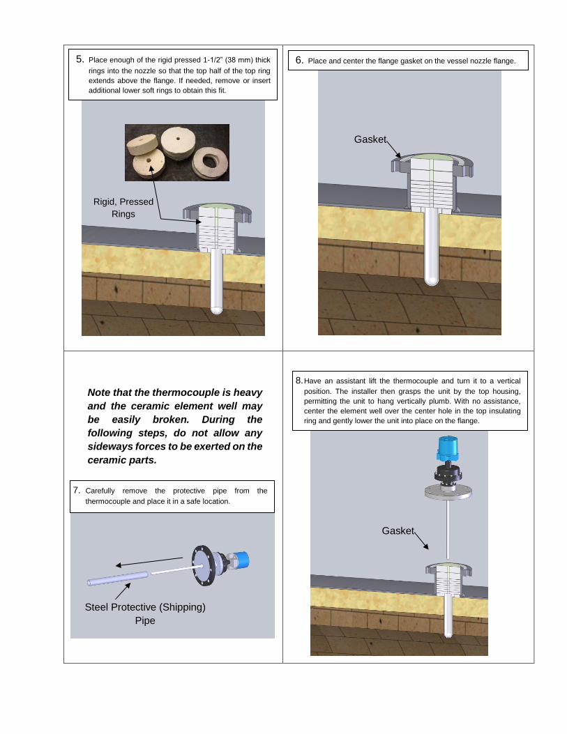
Note that the thermocouple is heavy
and the ceramic element well may
be easily broken. During the
following steps, do not allow any
sideways forces to be exerted on the
ceramic parts.
5. Place enough of the rigid pressed 1-1/2” (38 mm) thick
rings into the nozzle so that the top half of the top ring
extends above the flange. If needed, remove or insert
additional lower soft rings to obtain this fit.
Rigid, Pressed
Rings
Gasket
6. Place and center the flange gasket on the vessel nozzle flange.
7. Carefully remove the protective pipe from the
thermocouple and place it in a safe location.
Steel Protective (Shipping)
Pipe
8. Have an assistant lift the thermocouple and turn it to a vertical
position. The installer then grasps the unit by the top housing,
permitting the unit to hang vertically plumb. With no assistance,
center the element well over the center hole in the top insulating
ring and gently lower the unit into place on the flange.
Gasket

After installation and before reactor startup, perform
the Purge / Element Well Integrity Test on page 15.
This will verify that the element well was not broken
during installation, and that there are no problems with
the purge connections.
Performing this test as soon as possible prior to
reactor startup will allow time to obtain replacements
in the event of element well breakage. In general,
replacement is not possible while the reactor is
running. A thermocouple that has a broken element
well or that is improperly purged will only operate for
a short time before failing.
9. The soft compressible nozzle rings will
compress as the thermocouple is positioned into
place.
Compressible
Nozzle Rings
10. Keeping the unit centered on the flange, gently
rotate it to the desired position for electrical and
purge connections. Install and tighten the flange
studs.
11. Install instrument conduit, wiring and purge gas
tubing as described below.

Non-Vertical Installation
In non-vertical installations, insertion of the thermocouple unit can be difficult. The installer must attempt to
support the full weight of the thermocouple unit while fully inserting it into the centerline of the nozzle insulating
materials at the appropriate angle without allowing the weight of the unit to impart side-loads on the element
protective well.
The Model HMB Thermocouple Mounting Guide Bars provide an easy and safe means of inserting the heavy
thermocouple in non-vertical nozzles. The use of the guide bars minimizes the risk of breakage of the element
protective well due to misalignment of the unit with the nozzle centerline as it is being inserted into position.
A video showing the use of the HMB mounting bars is available at
http://www.youtube.com/watch?v=r2WmrERLEaQ
You can view the video on a smartphone by scanning the QR code shown here.
This space intentionally left blank

Non-Vertical Installation - Using the HMB Mounting Bars
1. Install the HRW refractory well and nozzle insulation rings as described in steps 1-5 beginning on page 8.
This hole for
150# flanges
2. Insert an R-Clip into the appropriate hole near the
threaded end of one of the mounting bars.
R-Clip
This hole for
300# flanges
Nozzle Flange
Mounting Bars
4. Similarly, install the other mounting bar on the opposite
bolt hole.
Stud with nut Flange Gasket
5. Place studs in 3 places as shown. Place the flange
gasket in position. The studs will temporarily hold
the flange gasket in position.
Purge connections
6. Making sure the thermocouple unit is correctly
rotated so that the purge and wiring connections are
oriented in the desired direction; allow the mounting
bars to support the weight of the thermocouple as it
is carefully guided into position.
Wiring connections
7. Loosely install studs and nuts in all empty holes to
hold the thermocouple in place as the guide bars
are removed.
9. Install the remaining studs and nuts. Assure the
flange and gasket is centered; tighten all to
specification.
10. Install instrument conduit, wiring and purge gas
connections as below.
8. Remove the mounting bar nuts. Using a large
screwdriver or pliers, pull the R-clips and remove
the mounting bars.
3. Place the threaded end of the mounting bar into a
vessel nozzle flange bolt hole as shown. Secure
the bar to the flange with the provided nut.
Wiring
The conduit connection to the terminal enclosure should be equipped with a union and a flexible conduit for ease of maintenance and to reduce strain on the terminal enclosure.
Verify that the insulation on thermocouple extension lead wire is rated for 400°F (200°C) continuous service.
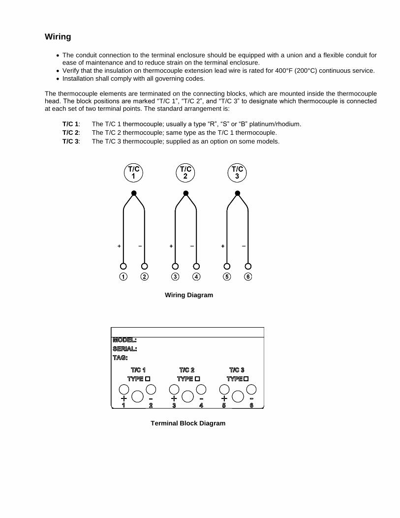
Installation shall comply with all governing codes. The thermocouple elements are terminated on the connecting blocks, which are mounted inside the thermocouple head. The block positions are marked “T/C 1”, “T/C 2”, and “T/C 3” to designate which thermocouple is connected at each set of two terminal points. The standard arrangement is:
T/C 1: The T/C 1 thermocouple; usually a type “R”, “S” or “B” platinum/rhodium.
T/C 2: The T/C 2 thermocouple; same type as the T/C 1 thermocouple.
T/C 3: The T/C 3 thermocouple; supplied as an option on some models.
Wiring Diagram
Terminal Block Diagram
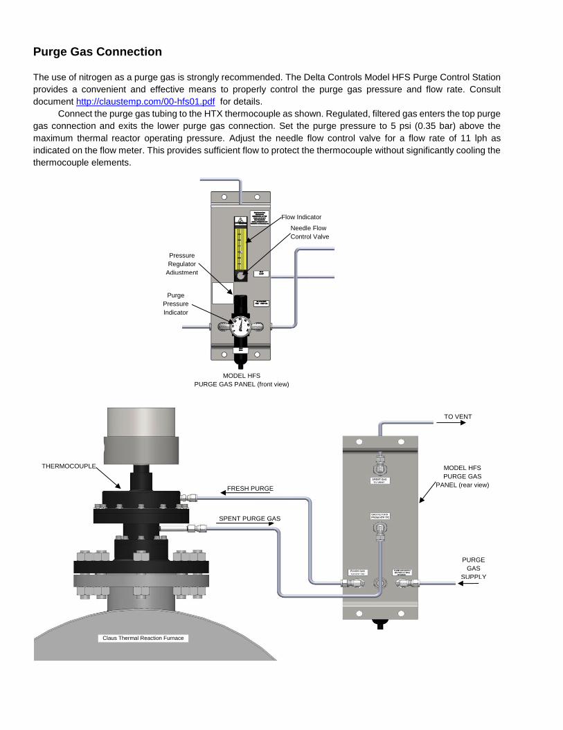
Purge Gas Connection
The use of nitrogen as a purge gas is strongly recommended. The Delta Controls Model HFS Purge Control Station
provides a convenient and effective means to properly control the purge gas pressure and flow rate. Consult
document http://claustemp.com/00-hfs01.pdf for details.
Connect the purge gas tubing to the HTX thermocouple as shown. Regulated, filtered gas enters the top purge
gas connection and exits the lower purge gas connection. Set the purge pressure to 5 psi (0.35 bar) above the
maximum thermal reactor operating pressure. Adjust the needle flow control valve for a flow rate of 11 lph as
indicated on the flow meter. This provides sufficient flow to protect the thermocouple without significantly cooling the
thermocouple elements.
TO VENT
PURGE
GAS
SUPPLY
MODEL HFS
PURGE GAS
PANEL (rear view)
FRESH PURGE
GAS
SPENT PURGE GAS
THERMOCOUPLE
Claus Thermal Reaction Furnace
Pressure
Regulator
Adjustment
Purge
Pressure
Indicator
Flow Indicator
Needle Flow
Control Valve
MODEL HFS
PURGE GAS PANEL (front view)
Purge/Element Well Integrity Test The following procedure should be performed after thermocouple installation to identify installation problems, and to verify that
the thermal well was not broken during installation. It should also be performed periodically (suggested weekly or bi-weekly) as
routine preventative maintenance.
1. Purge Pressure Setting – Verify that the purge pressure is at least 5 psi above the maximum operating pressure of the
reactor (normally 15 to 20 PSIG is suitable.) Adjust if necessary.
2. Purge Flow Setting – Verify the purge flow rate is correct: 11 LPH as indicated on the flow indicator. Adjust if necessary.
3. Check for Purge Integrity - Elevate the pressure on the HFS Purge Panel Pressure regulator by approximately 10 - 15
PSIG. Verify that the flow rate on the flow indicator increases. Reduce the pressure to its previous setting and verify
that the flow rate returns to its previous value. Note: depending on the amount of flow rate increase, cooling of
the thermocouple by the purge gas could show up as an apparent drop of a few degrees in reported temperature.
Failure of the flow indicator to respond to changes in purge pressure can indicate:
Leaks – which will allow the purge gas to escape to atmosphere and not return to the flow indicator.
Breakage of the element well – Which allows purge gas to escape into the reaction vessel and allows reaction gases
to contact the thermocouple element, leading to increasing inaccuracy and ultimately complete failure from
contamination and corrosion.
Plugging of the purge lines – usually, this is caused by an element well breakage. Sulfur condenses in the purge lines
and plugs them. Such a condition is often accompanied by a visible yellow sulfur deposit on the inside surface of the
glass flow indicator.
Technical Operation and Maintenance
Using Multiple Thermocouples within the HTX The model HTX can be equipped with up to 3 independent thermocouples in the same thermowell. On multiple
thermocouple units, thermocouple 1 is exposed to the interior of the thermowell. Thermocouple 2 is located adjacent
to thermocouple 1, but is encased in ceramic. In the event of a loss of purge or other conditions that could corrode
the thermocouple, thermocouple 1 will be begin to deteriorate due to exposure to corrosive gases. Thermocouple 2,
being somewhat protected by ceramic, will deteriorate at a slower rate. This will cause a widening difference in
reported temperature between the two thermocouples as deterioration progresses. Any discrepancy between the
thermocouple measurements is an indication that one or more junctions has been damaged.
Thermocouple 3 is typically one that offers a different range of temperatures than thermocouples 1 and 2. For
example, it is common to use type R or S for thermocouples 1 and 2 and use a type B for thermocouple 3. This will
allow the maximum possible range of measurement, since type R or S can read down to ambient temperatures, and
Type B can survive temperatures higher than types R or S, though type B cannot be used below about 100 °C.
Pre-Commissioning/Commissioning Procedure (Startup) Make sure that the purge is properly supplied to the thermocouple prior to reactor startup.
Use the Pressure Regulator adjustment on the HFS purge panel to set the Purge Pressure to approximately
5 psi above the maximum operating pressure of the reactor.
Using the Needle Flow Control Valve on the HFS purge panel, adjust the purge flow rate to 11 LPH as shown
on the flow indicator.
Shutdown Continue purging the thermocouple during shutdown until the reactor has cooled and reaction gases are no longer
present in the reactor.
Operation

The thermocouple has no adjustments or controls. Operation consists of maintaining purge gas flow to the
thermocouple.
Maintenance No periodic maintenance is required on the thermocouple. It is recommended that the Purge/Element Well Integrity
Test on page 15 be performed on a weekly or bi-weekly basis in order to assure that purge is maintained to the
thermocouple and to detect any breakage of the thermal well (which would lead to subsequent failure of the
thermocouple due to exposure to corrosive gases.) Such breakage is sometimes cause by shifting of the refractory
due to thermal expansion. When properly installed, the thermal well can withstand some shifting of the refractory,
but large shifts can cause failures.
The Model HTX is not intended to be repaired by unqualified persons. Do not open either of the purge chambers.
Doing so could compromise the reliability and safety of the product.
Troubleshooting For diagnostic procedures, see Delta Controls document AN-HTP39, available at www.claustemp.com/.

Specifications
Absolute Maximum Ratings: Maximum Process Pressure: 150psig (10 bar) Maximum Nitrogen Purge Pressure 30psig (2 bar) Maximum Process Temperature: 3272ºF (1800ºC)* Maximum Process Temperature (measured at Process Flange) 650 °F (343 °C) Maximum Rate of Temperature Change 200 °C / HR Minimum Operating Temperature: -4ºF (-20ºC) Maximum Process Flange Temperature: 446ºF (230ºC) see “X” below Maximum Terminal Enclosure Temperature 383ºF (195ºC)
Ingress Protection IP65 Hazardous Location Rating II 2 G Ex db IIB+H2 T2B Gb Applied Hazardous Location Standards IECEx: IEC 60079-0:2011 Ed. 6
IEC 60079-1:2014 Ed. 7 ATEX: EN 60079-0:2012/A11:2013;
EN 60079-1:2014
T/C types: B,S,R,K,T (“C” non-standard) Materials:
Main Body: 1117 or 1141 Carbon Steel Process Flange: SA-516-70 Carbon Steel Terminal Housing: Aluminum or Stainless Steel Trim/Bolting/Seats: Stainless Steel Protective well: Blended alumina, ceramic
Purge Requirements: dry nitrogen, 0.4scfh (11l/h) * type ‘B’ thermocouple. Max operating temperature is limited by the thermocouple melting point.

MODEL
BASIC TYPE
- T/C 1 - T/C 2 - T/C 3 -
INSERTION LENGTH
-
PROCESS CONNECTION
- OPTIONS
EXAMPLE HTX - B
- B
- R - 18.0” - 6”/150RS - AA
M/N OPTION
AA Aluminum Terminal Housing
XPB 304 SS Terminal Housing
Distance from
flange face to
inside face of
the refractory
M/N DESCRIPTION
HTX Basic Thermocouple
M/N PROCESS CONNECTION
6”/150RS ANSI 6in 150# Raised Face Flange Carbon Steel (SA516 70)
6"/150RY ANSI 6in 150# Raised Face Flange Stainless Steel (316)
6”/300RS ANSI 6in 300# Raised Face Flange Carbon Steel (SA516 70)
6”/300RY ANSI 6in 300# Raised Face Flange Stainless Steel (316)
specify
Other Sizes and Types (DIN, BS, etc.)
Carbon Steel or Stainless Steel
Min OD 228 mm Min thickness 23.8mm
Max OD 318mm Max thickness 36.6mm
M/N DESCRIPTION RANGE1
B Platinum +6% Rh (-) ─ Platinum +30% Rh (+) 212 - 3270°F (100 - 1800°C)
R Platinum (-) ─ Platinum +13% Rh (+) 32 - 3200°F (0 - 1760°C)
S Platinum (-) ─ Platinum +10% Rh (+) 32 - 3200°F (0 - 1760°C)
O None (T/C 2, T/C 3 only)
Auxiliary Components M/N DESCRIPTION – SEE SEPARATE DATA SHEETS
HRW Refractory Well
HNP Nozzle Packing Kit
HFS Flush Gas Control Station
H6G Refractory Drilling Kit
HRS Nozzle Refractory Stop
HMB Horizontal Mounting Bars
“X” behind the approval number indicates special conditions for safe use: Flamepath joints are not intended to
be repaired. Unit must only be disassembled or repaired by manufacturer. Flange temperature shall not
exceed 230˚C. Use Fasteners with M6 x 1mm 6g, 25 mm long 18-8 stainless steel with tolerance strength of ≥
70KPSI bolts. Fasteners incorporated in both lower and upper flange joints. Assembly shall be used with at
least minimum 124.24 mm [4.89”] high steel Nozzle with maximum wall thickness 11.252 mm[0.443”] and
maximum nozzle diameter 174.625 mm [6.875”]. Minimum 131.940 mm [5.1945”] refractory below the nozzle
shall be provided by the end user. Thermowell shall not extend more than 25.1 mm [1”] beyond the refractory
hot face. Temperature insulating material provided by manufacturer shall be installed inside the nozzle.
Refractory well provided by manufacturer shall be installed in the refractory bore hole. This equipment shall be
installed so that the flanged joints are not within 40 mm of a solid object that is not part of the equipment.
Terminal housing threaded conduit entries = ¾” NPT. Threaded adaptors size for Nitrogen connection = 1/8”
NPT
Model Numbering System

585 Fortson Street Shreveport, La. 71107 - USA P: +1(318) 424-8471 F: +1(318) 425-2421 [email protected] www.deltacnt.com