DNVGL-ST-E272 2.7-2 Offshore service...
50
STANDARD DNV GL AS The electronic pdf version of this document found through http://www.dnvgl.com is the officially binding version. The documents are available free of charge in PDF format. DNVGL-ST-E272 Edition February 2016 2.7-2 Offshore service modules
Transcript of DNVGL-ST-E272 2.7-2 Offshore service...
STANDARD
DNVGL-ST-E272 Edition February 2016
2.7-2 Offshore service modules
DNV GL AS
The electronic pdf version of this document found through http://www.dnvgl.com is the officially binding version. The documents are available free of charge in PDF format.

FOREWORD
DNV GL standards contain requirements, principles and acceptance criteria for objects, personnel,organisations and/or operations.© DNV GL AS February 2016
Any comments may be sent by e-mail to [email protected]
This service document has been prepared based on available knowledge, technology and/or information at the time of issuance of this document. The use of thisdocument by others than DNV GL is at the user's sole risk. DNV GL does not accept any liability or responsibility for loss or damages resulting from any use ofthis document.
C
hang
es –
cur
rent
CHANGES – CURRENTGeneralThis document supersedes DNV Standard for Certification 2.7-2, May 2013.
Text affected by the main changes in this edition is highlighted in red colour. However, if the changes
On 12 September 2013, DNV and GL merged to form DNV GL Group. On 25 November 2013 Det NorskeVeritas AS became the 100% shareholder of Germanischer Lloyd SE, the parent company of the GL Group,and on 27 November 2013 Det Norske Veritas AS, company registration number 945 748 931, changed itsname to DNV GL AS. For further information, see www.dnvgl.com. Any reference in this document to “DetNorske Veritas AS”, “Det Norske Veritas”, “DNV”, “GL”, “Germanischer Lloyd SE”, “GL Group” or any otherlegal entity name or trading name presently owned by the DNV GL Group shall therefore also be considereda reference to “DNV GL AS”.
On 12 September 2013, DNV and GL merged to form DNV GL Group. On 25 November 2013 Det NorskeVeritas AS became the 100% shareholder of Germanischer Lloyd SE, the parent company of the GL Group,and on 27 November 2013 Det Norske Veritas AS, company registration number 945 748 931, changed itsname to DNV GL AS. For further information, see www.dnvgl.com. Any reference in this document to “DetNorske Veritas AS”, “Det Norske Veritas”, “DNV”, “GL”, “Germanischer Lloyd SE”, “GL Group” or any otherlegal entity name or trading name presently owned by the DNV GL Group shall therefore also be considereda reference to “DNV GL AS”.
involve a whole chapter, section or sub-section, normally only the title will be in red colour.
Main changes February 2016• Title— Addition of 2.7-2 in title of document.
• All sections— Reference to DNV has been changed to DNV GL.— Reference to DNV Offshore Service Module Certificate has been changed to DNV GL product certificate.— All sections (except Sec.3): Addition of guidance notes, comments or clarification of existing
requirements within the standard.
• Sec.3 Structural technical requirements— Sec.3 has been restructured to present requirements in a more user friendly format.
In addition to the above stated main changes, editorial corrections may have been made.
Editorial corrections
Standard, DNVGL-ST-E272 – Edition February 2016 Page 3
DNV GL AS
C
onte
nts
CONTENTSCHANGES – CURRENT .................................................................................................. 3
Sec.1 Introduction................................................................................................. 71.1 Relationship with other standards, codes and regulations .....................7
1.1.1 The International Maritime Organization (IMO)...................................71.1.2 DNV Rules for Classification of Ships / DNV Offshore Standards............71.1.3 Relationship to previous revisions of this standard..............................7
Sec.2 General ......................................................................................................... 82.1 Objective................................................................................................82.2 Definitions .............................................................................................82.3 Referenced class rules, regulations and standards...............................102.4 Abbreviations .......................................................................................11
Sec.3 Structural technical requirements .............................................................. 123.1 General.................................................................................................123.2 Lifting ..................................................................................................13
3.2.1 Additional fittings for lifting ...........................................................13
3.3 Offshore installation induced loads .....................................................133.3.1 General ......................................................................................133.3.2 External / environmental loads ......................................................143.3.3 Other in-service & accidental loads.................................................16
3.4 Securing to offshore installation ..........................................................163.5 Fatigue .................................................................................................16
Sec.4 Safety related technical requirements ........................................................ 174.1 General.................................................................................................17
4.1.1 Detailed requirements ..................................................................174.1.2 Hazardous vs safe area.................................................................174.1.3 Alternative solutions.....................................................................17
4.2 Environmental requirements ................................................................174.3 Noise....................................................................................................184.4 Asbestos declarations ..........................................................................184.5 Electrical systems.................................................................................18
4.5.1 Safety requirements.....................................................................184.5.2 Components and equipment ..........................................................184.5.3 Arrangement & location of equipment .............................................194.5.4 Ingress protection........................................................................204.5.5 Electrical system main characteristics .............................................204.5.6 Earthing .....................................................................................204.5.7 Cables ........................................................................................224.5.8 Batteries.....................................................................................244.5.9 Equipment located external to module ............................................244.5.10 Programmable controllers ............................................................25
4.6 Ignition prevention ..............................................................................254.6.1 Requirements for electrical equipment exposed to hazardous
atmospheres ...............................................................................25
4.7 Fire & gas detection .............................................................................264.7.1 Gas detection and alarm system ....................................................264.7.2 Fire detection and alarm system ....................................................274.7.3 Emergency shutdown initiated from offshore installation ...................28
Standard, DNVGL-ST-E272 – Edition February 2016 Page 4
DNV GL AS
C
onte
nts
4.8 Communications ..................................................................................284.8.1 Public address and general alarm system (PA/GA) ............................284.8.2 Telephone / two way communication ..............................................28
4.9 Fire fighting..........................................................................................284.9.1 Portable extinguishers ..................................................................294.9.2 Fixed extinguishing systems ..........................................................29
4.10 Passive fire protection..........................................................................304.10.1 General ......................................................................................304.10.2 Restricted use of combustible materials ..........................................31
4.11 Escape..................................................................................................314.11.1 Doors .........................................................................................314.11.2 Emergency exits and escape routes ................................................314.11.3 Emergency lighting ......................................................................32
4.12 Heating, ventilation and air conditioning..............................................324.12.1 Air inlets/ outlets .........................................................................324.12.2 Natural ventilation .......................................................................324.12.3 Mechanical ventilation ..................................................................324.12.4 Over-pressurised ventilation systems..............................................34
Sec.5 Module Service Types................................................................................. 365.1 Modules for important services ............................................................365.2 Module types ........................................................................................375.3 Specific requirements for functional groups ........................................38
5.3.1 Combustion engines .....................................................................385.3.2 Air Compressors ..........................................................................395.3.3 Steam generators ........................................................................395.3.4 Well intervention equipment ..........................................................415.3.5 Diving systems ...........................................................................415.3.6 Hydrocarbon containing equipment ................................................415.3.7 Drilling service equipment .............................................................41
5.4 Offshore installations not intended for hydrocarbon related activities .425.4.1 Inclination on non-important service equipment ...............................425.4.2 Batteries.....................................................................................425.4.3 Gas detection ..............................................................................425.4.4 Combustion engines and steam generators......................................42
Sec.6 Installation and hook-up............................................................................ 436.1 General.................................................................................................436.2 Interfaces between module and offshore installation...........................43
6.2.1 Signal from module or equipment to CCR ........................................436.2.2 Signals from CCR to module or equipment.......................................43
6.3 Instructions for hook-up/installation...................................................44Sec.7 Marking and instructions............................................................................ 45
7.1 Information plate .................................................................................457.2 Marking of equipment ..........................................................................45
Sec.8 Approval and certification procedures........................................................ 478.1 General.................................................................................................478.2 Application for certification ..................................................................478.3 Approval schemes ................................................................................478.4 Design assessment...............................................................................488.5 Survey and testing ..............................................................................48
Standard, DNVGL-ST-E272 – Edition February 2016 Page 5
DNV GL AS
C
onte
nts
8.6 Certification of existing containers.......................................................488.7 Retention of certificates ......................................................................488.7.1 Maintenance of certificates /periodic inspections...............................488.7.2 Modifications ...............................................................................498.7.3 Withdrawal of certification.............................................................49
Standard, DNVGL-ST-E272 – Edition February 2016 Page 6
DNV GL AS
This standard for certification has been issued in order to collect into one document a suitable collection of requirements with relevant appropriate references to various international codes and standards which are applicable to the design and installation of offshore service modules.
Offshore service modules are designed to perform temporary services on offshore installations and may be placed on different offshore installations and units in different national waters.
This standard for certification applies basic requirements from other DNV GL rules and standards to offshore service modules and has been based primarily on recognised practices for the offshore industry. It is intended that the standard will be suitable for global usage. It should, however, be noted that some shelf or flag states may have stricter or other requirements than those given in this standard.
Modules designed and manufactured in compliance with DNV 2.7-2 are intended to meet the basic requirements of SOLAS, MODU code and DNV Offshore Standards relevant to the functions of the equipment and as applicable at date this standard was issued. All subject to adequate installation of the equipment when located on the offshore installation (which is out with the scope of this standard).
DNV, DNV GL and associated logos are registered trademarks of DNV GL AS and may not be used without prior permission of DNV GL.
1.1 Relationship with other standards, codes and regulations
1.1.1 The International Maritime Organization (IMO)The requirements in the SOLAS Code apply for Offshore Service Modules utilised on ships and certain floating offshore installations. The requirements in the MODU Code apply for offshore service modules utilised on floating offshore drilling units, including jack-up installations. This applies irrespective of the time such modules are installed and used.
DNV 2.7-2 is intended to meet the basic safety requirements of SOLAS and MODU code with regard to escape provision, fire detection and fire protection.
1.1.2 DNV Rules for Classification of Ships / DNV Offshore Standards.Offshore service modules that are installed on a DNV GL classed offshore Installation may be subject to classification requirements, either in main class or other class notations. DNV 2.7-2 includes the basic requirements of these documents, for main class items, when applied to temporary installations. DNV 2.7-2 is not intended to replace certification to the DNV Rules for Classification of Ships/DNV Offshore Standards for permanently installed equipment or conversions. Equipment needing type approval or product certification or type approval certificate (as defined in DNV Rules for Ships or Offshore Standards) shall be certified in accordance with the relevant rules/ standard prior to commissioning and use in a DNV 2.7-2 module.
When equipment is located on a DNV GL classed offshore installation it is required to be assessed by DNV GL to ensure any aspects which interface with a class systems have been correctly installed and to ensure that general safety principles have been adhered. This considers the location/integration of the equipment and confirms that relevant installation and hook-up requirements specified in the DNV GL product certificate have been satisfied. It is not the intention of this standard to address the requirements for commissioning on a DNV GL class unit, these remain the responsibility of the vessel/offshore unit owner/manager.
1.1.3 Relationship to previous revisions of this standardThis revision has been published to provide additional information and clarifications on a limited number of existing requirements, as presented in the May 2013 edition, with the intention of simplifying the implementation of these requirements. Minor typing errors have also been corrected in this revision.
Design assessment and certification to the previous revision of this standard shall not be conducted six months following release of this revision.
Standard, DNVGL-ST-E272 – Edition February 2016 Page 7
DNV GL AS
2.1 ObjectiveThe objective of this standard for certification is to set requirements for offshore service modules focussed on the safety impact to the offshore installation upon which the equipment is installed.
When installed and used on floating offshore installations, service containers are subject to the regulations applicable to an offshore installation (i.e., IMO MODU/SOLAS, Class, flag state and national regulations). When offshore service containers are installed and used on fixed offshore installations, national regulations will apply.
It has been recognised that individual interpretations of all the various codes and standards may sometimes lead to conflicting requirements. This standard for certification intends to prescribe solutions which will provide an equivalent level of safety as the codes and standards referred to throughout this document.
Certification by DNV GL provides a document which may be presented to users of the module to document its technical standard and safety performance. The certificate also defines conditions for transportation to, and installation on, an offshore installation.
2.2 Definitions Accommodation space
Those used for public spaces, corridors, lavatories, cabins, offices, hospitals, cinemas, games and hobbies rooms, pantries containing no cooking appliances and similar spaces. Public spaces are those portions of the accommodation which are used for halls, dining rooms, lounges and similar permanently enclosed spaces.
Guidance note:The term “cabins” relates to sleeping areas. “Offices” are considered as spaces for paperwork/administrative tasks only. Facilities for office work incorporated into the same space as low voltage control/monitoring equipment or laboratories, without an internal source of release, would not be considered an office/accommodation space.
---e-n-d---of---g-u-i-d-a-n-c-e---n-o-t-e---
Category A machinery space:
All spaces which contain internal combustion-type machinery used either for main propulsion or for other purposes where such machinery has in the aggregate a total power of not less than 375 kW or which contain any oil-fired boiler or oil fuel unit; and trunks to such spaces.
Certified safe equipment:
Certified safe equipment is equipment certified by an independent national test institution or competent body to be in accordance with a recognised standard for electrical apparatus in hazardous areas.
Essential/safety system:
Module integrated systems including required utilities, which are provided to prevent, detect or warn of an accidental event and/or mitigate its effect. This may include;
— fire and gas detection systems— shutdown systems— PA/GA systems— supplies from emergency power or UPS sources— fire protection and extinguishing system.
Extreme location:
Areas which are out with the range of locations defined for Mid-point location.
Gas tight:
Doors, walls or dampers which will maintain a pressure differential between adjacent areas, the allowable leakage rate will not exceed 0.5 m3/ m2h at +50Pa.
Standard, DNVGL-ST-E272 – Edition February 2016 Page 8
DNV GL AS
Services provided by the module to the offshore installation which are critical to the safety of the offshore installation or modules that prevent, protect or mitigate from the effects of an accidental event. Examples may include accommodation units, emergency generator units, well intervention equipment.
Low flame spread:
A surface, which in accordance with the IMO Fire Test Procedures (FTP) Code, will adequately restrict the spread of flame.
Manned:
Manned for more than 2-hours in a 24-hour period. If manning is provided and located externally requirements for emergency lighting and ventilation are not considered mandatory.
Maximum operational weight
Maximum weight of the module during operation on deck, including materials, fluids (e.g. diesel, water or hydraulic fluid) or process materials (e.g. mud, cuttings) contained in the unit during operation (this may be different to the Maximum Rating defined for the purposes of transportation and lifting).
Mid-point location:
Area between 0.2 and 0.7 times the offshore installation/vessel length, measured from the aft.
Non-combustible material:
Material which neither burns nor gives off flammable vapours in sufficient quantity for self-ignition when heated to approximately 750°C, this being determined in accordance with the IMO Fire Test Procedures (FTP) Code.
Offshore container:
A portable container with a maximum gross mass not exceeding 25,000 kg, for repeated use in the transport of goods or equipment, handled in open seas, to, from or between fixed and/or floating offshore installations and ships. See DNV 2.7-1 for a more detailed definition.
Offshore installation:
This is used as a short term and may be a fixed offshore installation, a mobile offshore unit or a ship on which the module may be located.
Offshore service module:
A unit built and equipped for a special service task, mainly for temporary installation, on offshore installations.
This applies equally to offshore frames with equipment but for ease of reference we will refer throughout the standard to offshore service modules.
Portable offshore unit:
A “POU” (portable offshore unit) is a package or unit intended for repeated or single offshore transportation and installation/lifting. POU’s may also be designed for subsea lifting. See DNV 2.7-3 for more detailed definition.
Primary deck covering:
Deck covering which will not readily ignite in accordance with the IMO Fire Test Procedures (FTP) Code.
Short circuit proof
Installation following one of the following methods:
— bare conductors mounted on isolating supports— single core cables (i.e. conductors with both insulation and overall jacket) without metallic screen or
armour or braid, or with the braid fully insulated by heat shrink sleeves in both ends— insulated conductors (wires) from different phases kept separated from each other and from earth by
supports of insulating materials, or by the use of outer extra sleeves
Standard, DNVGL-ST-E272 – Edition February 2016 Page 9
DNV GL AS
Source of release
Point or location from which a flammable substance may be released into the room or building such that an explosive gas atmosphere could be formed.
Standard fire test:
A test in which specimens of the relevant bulkheads or decks are exposed in a test furnace to temperatures corresponding approximately to the standard time-temperature in accordance with the test method specified in the IMO Fire Test Procedures (FTP) code.
Unmanned:
Areas not ‘manned’ in accordance with the definition in this standard.
2.3 Referenced class rules, regulations and standardsThe following standards include provisions which, through reference in the text, constitute provisions of this standard. The latest issue of the references will be used unless otherwise agreed. Where the referenced DNV standard in this document has been superseded by a DNV GL version, the DNV GL version shall be considered as the latest issue. Other recognised standards may be used provided it can be demonstrated that these meet or exceed the requirements of the standards referenced below:
— IMO requirements:
— CSC, IMO Convention for Safe Containers — IMO FSS, International Code for Fire Safety Systems — IMO FTP, International Code for Application of Fire Test Procedures— MSC.1/Circ. 1275 – Unified Interpretation of SOLAS Chapter II-2 on the number and arrangement
of portable fire extinguishers on board ships— MODU, IMO Code Mobile Offshore Drilling Units — SOLAS, IMO Convention Safety of Life at Sea.
— DNV Classification Note No. 8 Conversion Of Ships— DNV Offshore Standards:
— DNV-OS-A101- Safety Principles and Arrangements— DNV-OS-D101- Marine and Machinery Systems and Equipment— DNV-OS-D201- Electrical Installations— DNV-OS-D301- Fire Protection— DNV-OS-E101- Drilling Plant— DNV-OS-E201- Oil and Gas Processing Systems— DNV-OS-E402- Offshore Standard for Diving Systems.
— DNV Rules for Ships Pt.3, Ch.1 - Hull Structural Design— DNV Service Specification DNV-DSS-105- Rules for Classification of Diving Systems— DNV Standard DNV-DS-E403- Standard for Surface Diving Systems— DNV Standard for Certification:
— DNV STC 1.2 Type Approval— DNV STC 2.22 Lifting Appliances— DNV STC 2.4 Environmental Test Specification for Instrumentation and Automation Equipment— DNV STC 2.7-1 Offshore Containers— DNV STC 2.7-3 Portable Offshore Units.
Standard, DNVGL-ST-E272 – Edition February 2016 Page 10
DNV GL AS
— IEC 60079 Series - Explosive atmospheres— IEC 60092 Series - Electrical installations in Ships— IEC 61892 Series - Mobile and fixed offshore units – Electrical installations.
— NORSOK publications:
— Norsok E-001 – Electrical Systems— Norsok Z-015 – Temporary Equipment.
2.4 AbbreviationsTable 2-1 Abbreviation
Abbreviation DescriptionCCR central control room
DNV DNV GL
DNV 2.7-1 Offshore Containers
DNV 2.7-2 Offshore Service Modules
DNV 2.7-3 Portable Offshore Units
EMC electro magnetic compatibility
EN European Normative Standard
ESD emergency shutdown
EU/EEA European Union / European Economic Area
F&G fire and gas
FSS fire safety systems
FTP fire test procedure
IEC International Electro-technical Commission
IMDG The International Maritime Dangerous Goods Code
IMO International Maritime Organisation
IP ingress protection
LEL lower explosive limit
MODU IMO Code Mobile Offshore Drilling Units
MOU mobile offshore unit
P & ID piping and instrumentation diagram
PA/GA public address / general alarm
PFP passive fire protection
PLC programmable logic controller
POU portable offshore unit
SOLAS IMO Convention Safety of Life at Sea
STC DNV standard for certification
UPS uninterruptable power supply
Standard, DNVGL-ST-E272 – Edition February 2016 Page 11
DNV GL AS
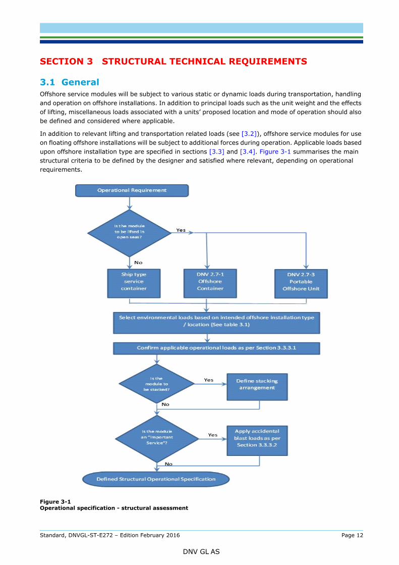
3.1 GeneralOffshore service modules will be subject to various static or dynamic loads during transportation, handling and operation on offshore installations. In addition to principal loads such as the unit weight and the effects of lifting, miscellaneous loads associated with a units’ proposed location and mode of operation should also be defined and considered where applicable.
In addition to relevant lifting and transportation related loads (see [3.2]), offshore service modules for use on floating offshore installations will be subject to additional forces during operation. Applicable loads based upon offshore installation type are specified in sections [3.3] and [3.4]. Figure 3-1 summarises the main structural criteria to be defined by the designer and satisfied where relevant, depending on operational requirements.
Figure 3-1 Operational specification - structural assessment
Standard, DNVGL-ST-E272 – Edition February 2016 Page 12
DNV GL AS
Units certified to DNV 2.7-2 shall also be approved and certified by DNV GL using one of the three following schemes:
— Standard for Certification No. DNV 2.7-1, (including IMO/MSC/Circ.860) Offshore Containers
— Standard for Certification No. DNV 2.7-3, Portable Offshore Units
— Ship type service containers – These will not be used for lifting between vessels and/or offshore installations at sea.
Guidance note 1:Offshore containers and portable offshore units certified by another organisation shall be considered on a case by case basis following verification of the design and surveillance of the container/unit.
---e-n-d---of---g-u-i-d-a-n-c-e---n-o-t-e---
Guidance note 2:Units should be certified as ISO/CSC containers if sea-transportation as a freight container is required.
Building units as ISO/CSC containers will facilitate international transport by sea, since such units can be carried as standardized cargo units on container carriers and other dry cargo ships. Modules that are not ISO/CSC containers will normally be transported as special cargo.
Modules built according to ISO freight container standards, ISO 1496 must be certified to IMO’s Convention for Safe containers, CSC. The structural requirements in ISO 1496 and CSC are related to transport and handling, and are not generally relevant for units when installed on ships or offshore installations and as such will be subject to the additional requirements outlined in this Section.
---e-n-d---of---g-u-i-d-a-n-c-e---n-o-t-e---
Guidance note 3:Modules which are based on ship type service containers may not require certification of the primary frame with respect to lifting; these modules are not subject to lifting in open seas. The requirements for certification will be dictated by the end user and/or local regulations prevalent in the country in which it is lifted. Unless explicitly requested, lifting aspects will not be addressed during the certification process for ship type service containers.
---e-n-d---of---g-u-i-d-a-n-c-e---n-o-t-e---
3.2.1 Additional fittings for liftingIn addition to the pad eyes and slings used for offshore handling, some Offshore Containers and Portable Offshore Units are built with extra sets of fittings for lifting and handling. These may include pad eyes, tugger points, etc used for handing the module on an offshore installation only. Such equipment, including the supporting structure, must be dimensioned according to DNV 2.7-1, DNV 2.7-3 or DNV Standard for Certification No. 2.22, Lifting Appliances.
These additional fittings must not be used to lift a module unit to or from a supply vessel. This will be stated in the certificate and shall be clearly marked on the module.
3.3 Offshore installation induced loads
3.3.1 GeneralInstallation induced and other miscellaneous loads should be defined and documented by the Designer and/or Customer – realistic values may be specified for generic operational conditions. Additional loads shall be considered applicable for “important service” modules (see section [3.3.3.2]). Operational limitations used as the basis for approval will be specified in the DNV GL product certificate.
It is recommended that the thickness of the module outer walls be a minimum of 4 mm however shall be demonstrated as sufficient to withstand the loads specified in this section. Special attention should be paid to buckling control of thin-plated structures subject to compressive stresses.
Allowable bending and shear stresses shall be taken as 160f1 and 90f1 N/mm2 respectively where f1 is the relevant material factor (reference DNV Rules for Classification of Ships, Pt.3 Ch.1).
Standard, DNVGL-ST-E272 – Edition February 2016 Page 13
DNV GL AS
The plate flanges of corrugated/stiffened-plates should be checked for buckling in accordance with DNV Rules for Ships Pt.3 Ch.1 Sec. 13. The compression stress σb in the plate flange, induced by lateral pressure and local bending of the plate profile, should not exceed the critical buckling stress times utilisation factor for normal load level σc x η. For loads applied on normal load level η = 0.80.
---e-n-d---of---g-u-i-d-a-n-c-e---n-o-t-e---
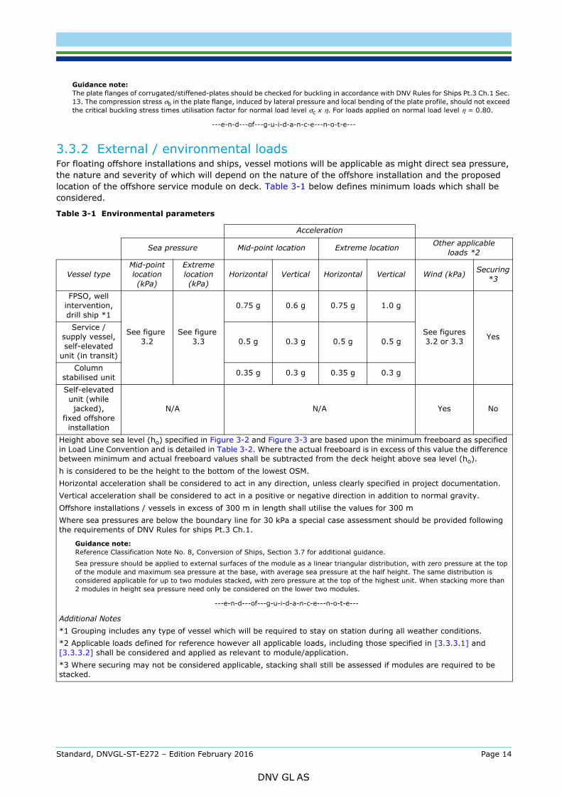
3.3.2 External / environmental loadsFor floating offshore installations and ships, vessel motions will be applicable as might direct sea pressure, the nature and severity of which will depend on the nature of the offshore installation and the proposed location of the offshore service module on deck. Table 3-1 below defines minimum loads which shall be considered.
Table 3-1 Environmental parameters
Acceleration
Sea pressure Mid-point location Extreme location Other applicable loads *2
Vessel typeMid-point location (kPa)
Extreme location (kPa)
Horizontal Vertical Horizontal Vertical Wind (kPa) Securing *3
FPSO, well intervention, drill ship *1
See figure 3.2
See figure 3.3
0.75 g 0.6 g 0.75 g 1.0 g
See figures 3.2 or 3.3 Yes
Service / supply vessel, self-elevated
unit (in transit)
0.5 g 0.3 g 0.5 g 0.5 g
Column stabilised unit 0.35 g 0.3 g 0.35 g 0.3 g
Self-elevated unit (while jacked),
fixed offshore installation
N/A N/A Yes No
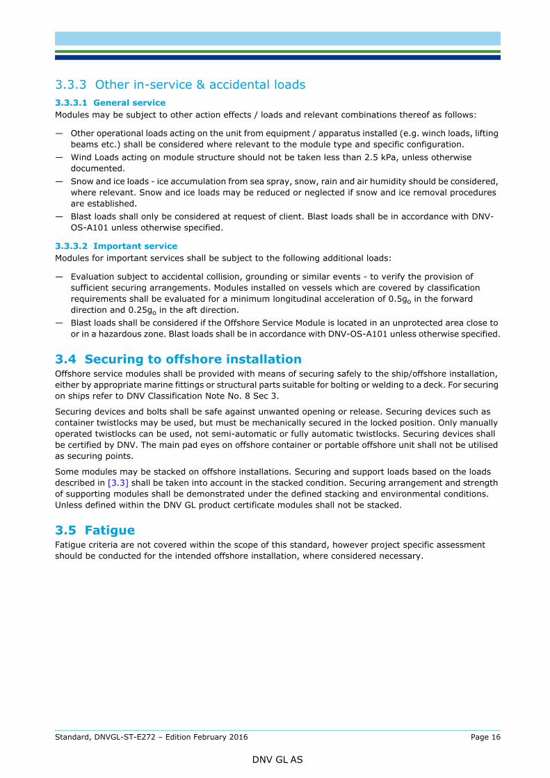
Height above sea level (ho) specified in Figure 3-2 and Figure 3-3 are based upon the minimum freeboard as specified in Load Line Convention and is detailed in Table 3-2. Where the actual freeboard is in excess of this value the difference between minimum and actual freeboard values shall be subtracted from the deck height above sea level (ho).h is considered to be the height to the bottom of the lowest OSM.Horizontal acceleration shall be considered to act in any direction, unless clearly specified in project documentation.Vertical acceleration shall be considered to act in a positive or negative direction in addition to normal gravity.Offshore installations / vessels in excess of 300 m in length shall utilise the values for 300 mWhere sea pressures are below the boundary line for 30 kPa a special case assessment should be provided following the requirements of DNV Rules for ships Pt.3 Ch.1.
Guidance note:Reference Classification Note No. 8, Conversion of Ships, Section 3.7 for additional guidance.
Sea pressure should be applied to external surfaces of the module as a linear triangular distribution, with zero pressure at the top of the module and maximum sea pressure at the base, with average sea pressure at the half height. The same distribution is considered applicable for up to two modules stacked, with zero pressure at the top of the highest unit. When stacking more than 2 modules in height sea pressure need only be considered on the lower two modules.
---e-n-d---of---g-u-i-d-a-n-c-e---n-o-t-e---
Additional Notes*1 Grouping includes any type of vessel which will be required to stay on station during all weather conditions.*2 Applicable loads defined for reference however all applicable loads, including those specified in [3.3.3.1] and [3.3.3.2] shall be considered and applied as relevant to module/application.*3 Where securing may not be considered applicable, stacking shall still be assessed if modules are required to be stacked.
Standard, DNVGL-ST-E272 – Edition February 2016 Page 14
DNV GL AS
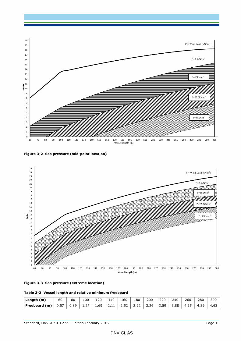
Figure 3-2 Sea pressure (mid-point location)
Figure 3-3 Sea pressure (extreme location)
Table 3-2 Vessel length and relative minimum freeboard
Length (m) 60 80 100 120 140 160 180 200 220 240 260 280 300
Freeboard (m) 0.57 0.89 1.27 1.69 2.11 2.52 2.92 3.26 3.59 3.88 4.15 4.39 4.63
P=7.5kN/m2
P = Wind Load (kN/m2)
P=15kN/m2
P=22.5kN/m2
P=30kN/m2
P=30kN/m2
P=22.5kN/m2
P=15kN/m2
P=7.5kN/m2
P = Wind Load (kN/m2)
Standard, DNVGL-ST-E272 – Edition February 2016 Page 15
DNV GL AS
3.3.3.1 General serviceModules may be subject to other action effects / loads and relevant combinations thereof as follows:
— Other operational loads acting on the unit from equipment / apparatus installed (e.g. winch loads, lifting beams etc.) shall be considered where relevant to the module type and specific configuration.
— Wind Loads acting on module structure should not be taken less than 2.5 kPa, unless otherwise documented.
— Snow and ice loads - ice accumulation from sea spray, snow, rain and air humidity should be considered, where relevant. Snow and ice loads may be reduced or neglected if snow and ice removal procedures are established.
— Blast loads shall only be considered at request of client. Blast loads shall be in accordance with DNV-OS-A101 unless otherwise specified.
3.3.3.2 Important serviceModules for important services shall be subject to the following additional loads:
— Evaluation subject to accidental collision, grounding or similar events - to verify the provision of sufficient securing arrangements. Modules installed on vessels which are covered by classification requirements shall be evaluated for a minimum longitudinal acceleration of 0.5go in the forward direction and 0.25go in the aft direction.
— Blast loads shall be considered if the Offshore Service Module is located in an unprotected area close to or in a hazardous zone. Blast loads shall be in accordance with DNV-OS-A101 unless otherwise specified.
3.4 Securing to offshore installationOffshore service modules shall be provided with means of securing safely to the ship/offshore installation, either by appropriate marine fittings or structural parts suitable for bolting or welding to a deck. For securing on ships refer to DNV Classification Note No. 8 Sec 3.
Securing devices and bolts shall be safe against unwanted opening or release. Securing devices such as container twistlocks may be used, but must be mechanically secured in the locked position. Only manually operated twistlocks can be used, not semi-automatic or fully automatic twistlocks. Securing devices shall be certified by DNV. The main pad eyes on offshore container or portable offshore unit shall not be utilised as securing points.
Some modules may be stacked on offshore installations. Securing and support loads based on the loads described in [3.3] shall be taken into account in the stacked condition. Securing arrangement and strength of supporting modules shall be demonstrated under the defined stacking and environmental conditions. Unless defined within the DNV GL product certificate modules shall not be stacked.
3.5 FatigueFatigue criteria are not covered within the scope of this standard, however project specific assessment should be conducted for the intended offshore installation, where considered necessary.
Standard, DNVGL-ST-E272 – Edition February 2016 Page 16
DNV GL AS
4.1 General
4.1.1 Detailed requirementsThe details given in this chapter describe the technical requirements which apply to an Offshore Service Module; some requirements are generic and will apply to all units. Others are specific and shall only be applied when defined in 5.
4.1.2 Hazardous vs safe areaModules located on open deck on an offshore installation shall be suitably rated for the actual rating of zone in which they are located, but it is important to recognise that all equipment is required to be made safe in case of accidental release of gas. This means that any equipment which remains electrically energised or has the potential to have surface temperatures in excess of 200°C following shutdown on gas detection shall be designed and installed to meet the requirements of minimum zone 2 and in some cases zone 1.
Equipment which remains energised during gas detection or produces a hot surface shall meet a minimum of Gas Group IIA and Temperature Class T3.
4.1.3 Alternative solutionsAlternative solutions may be substituted where shown to provide an equivalent or higher level of integrity or safety than the requirements under this standard. Justification of alternative solutions shall be documented.
Where alternative solutions have been accepted this shall be documented on the DNV GL product certificate.
4.2 Environmental requirementsModules shall be suitable for defined environmental conditions. Table 4-1 is applicable to all modules, Table 4-2 shall be considered for particular modules designed for important services as defined in [2.2].
Table 4-1 Environmental conditions – all modules
Outside ambient temperature: –20oC to +45°C
Humidity: Up to 96% without condensation when heating is provided (mounted indoors) or 100% with condensation when mounted outdoors.
Electromagnetic compatibility
All electrical equipment shall be selected and installed so as to avoid EMC problems. Reference standards which can be used to demonstrate compliance:IEC 61000-6-2 (Immunity)IEC 61000-6-4 (Emissions)
Inclination
The maximum operational inclination for the module should be specified. This maximum shall be defined at the point where continued operation of the equipment changes to a level where it presents a risk to the operator, offshore installation or if there is an increase in surface temperature beyond 200°C. Should no inclination values be specified the module shall be marked on the certificate as suitable for use on a fixed offshore installation only.
Standard, DNVGL-ST-E272 – Edition February 2016 Page 17
DNV GL AS
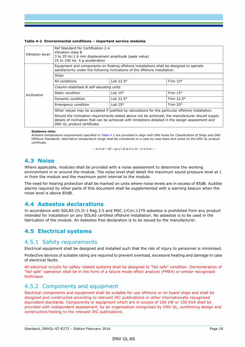
Guidance note:Ambient temperature requirements specified in Table 4-1 are provided to align with DNV Rules for Classification of Ships and DNV Offshore Standards. Alternative temperature range shall be considered on a case by case basis and noted on the DNV GL product certificate.
---e-n-d---of---g-u-i-d-a-n-c-e---n-o-t-e---
4.3 NoiseWhere applicable, modules shall be provided with a noise assessment to determine the working environment in or around the module. The noise level shall detail the maximum sound pressure level at 1 m from the module and the maximum point internal to the module.
The need for hearing protection shall be marked on units where noise levels are in excess of 85dB. Audible alarms required by other parts of this document shall be supplemented with a warning beacon when the noise level is above 85dB.
4.4 Asbestos declarationsIn accordance with SOLAS Ch.II-1 Reg.3.5 and MSC.1/Circ.1379 asbestos is prohibited from any product intended for installation on any SOLAS certified offshore installation. No asbestos is to be used in the fabrication of the module. An Asbestos free declaration is to be issued by the manufacturer.
4.5 Electrical systems
4.5.1 Safety requirementsElectrical equipment shall be designed and installed such that the risk of injury to personnel is minimised.
Protective devices of suitable rating are required to prevent overload, excessive heating and damage in case of electrical faults.
All electrical circuits for safety related systems shall be designed to “fail safe” condition. Demonstration of “fail safe” operation shall be in the form of a failure mode effect analysis (FMEA) or similar recognised technique.
4.5.2 Components and equipmentElectrical components and equipment shall be suitable for use offshore or on board ships and shall be designed and constructed according to relevant IEC publications or other internationally recognised equivalent standards. Components or equipment which are in excess of 100 kW or 100 kVA shall be provided with independent assessment, by an organisation recognised by DNV GL, confirming design and construction/testing to the relevant IEC publications.
Table 4-2 Environmental conditions – important service modules
Vibration level:
Ref Standard for Certification 2.4Vibration class B 3 to 25 Hz:1.6 mm displacement amplitude (peak value)25 to 100 Hz: 4 g acceleration
Inclination
Equipment and components on floating offshore installations shall be designed to operate satisfactorily under the following inclinations of the offshore installation: Ships
All conditions List 22.5° Trim 10°
Column-stabilised & self-elevating units
Static condition List 15° Trim 15°
Dynamic condition List 22.5° Trim 22.5°
Emergency condition List 25° Trim 25°
Other values may be accepted if justified by calculations for the particular offshore installation.Should the inclination requirements stated above not be achieved, the manufacturer should supply details of inclination that can be achieved with limitations detailed in the design assessment and DNV GL product certificate.
Standard, DNVGL-ST-E272 – Edition February 2016 Page 18
DNV GL AS
while the circuits are live shall have covers or otherwise be arranged such that touching or short circuiting of live parts is not possible.
Component insulating materials shall be flame retardant according to IEC 60092-101 or equivalent.
In instances where a specific requirement is not detailed for electrical installation/equipment within the standard the IEC 61892 series of standards, current at time of publication of this standard, shall be utilised to determine the applicable requirement.
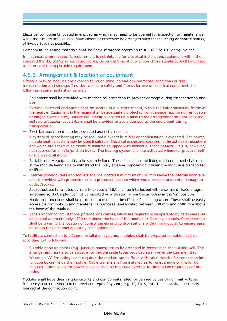
4.5.3 Arrangement & location of equipmentOffshore Service Modules are exposed to rough handling and environmental conditions during transportation and storage. In order to ensure safety and fitness for use of electrical equipment, the following requirements shall be met:
— Equipment shall be provided with mechanical protection to prevent damage during transportation and use.
— External electrical enclosures shall be located in a suitable recess, within the outer structural frame of the module. Equipment in the recess shall be adequately protected from damage (e.g. use of removable or hinged cover plates). Where equipment is located on a base frame arrangement and not enclosed, suitable protection covers/bars shall be provided to avoid damage to the equipment during transportation.
— Electrical equipment is to be protected against corrosion.— A system of space heating may be required if excess humidity or condensation is expected. The normal
module heating system may be used if suitable. Electrical enclosures exposed to the outside atmosphere and which are sensitive to moisture shall be equipped with individual space heaters. This is, however, not required for simple junction boxes. The heating system shall be activated whenever practical both onshore and offshore.
— Portable utility equipment is to be securely fixed. The construction and fixing of all equipment shall result in the module being able to withstand the likely stresses imposed on it when the module is transported or lifted.
— Internal power outlets and sockets shall be located a minimum of 300 mm above the internal floor level unless provided with protection or in a protected location which would prevent accidental damage to outlet /socket.
— Socket outlets for a rated current in excess of 16A shall be interlocked with a switch or have integral switching so that a plug cannot be inserted or withdrawn when the switch is in the ‘on’ position.
— Hook-up connections shall be protected to minimise the effects of splashing water. These shall be easily accessible for hook-up and maintenance purposes, and located between 600 mm and 1500 mm above the base of the module.
— Panels and/or control stations (internal or external) which are required to be operated by personnel shall be located approximately 1500 mm above the base of the module or floor level panels. Consideration shall be given to the location of control panels and control stations within the module, to ensure ease of access for personnel operating the equipment.
To facilitate connection to offshore installation systems, modules shall be prepared for cable hook-up according to the following:
— Suitable hook up points (e.g. junction boxes) are to be arranged in recesses on the outside wall. This arrangement may also be suitable for flexible cable types provided strain relief devices are fitted.
— Where an “A” fire rating is not required the module can be fitted with cable transits for connection into junction boxes inside the module. Cable transits shall be installed as to resist smoke or fire for 60 minutes. Connections for power supplies shall be mounted external to the module regardless of fire rating.
Modules shall have their in-take circuits and components rated for defined values of nominal voltage, frequency, current, short circuit level and type of system, e.g. IT, TN-S, etc. This data shall be clearly marked at the connection point.
Standard, DNVGL-ST-E272 – Edition February 2016 Page 19
DNV GL AS
connected, i.e. without excessive bending of the conductor ends and without having to unscrew terminals or other parts.
Guidance note:The offshore installation should have pre-installed junction boxes or socket outlets within a reasonable vicinity such that the modules can be conveniently connected.
---e-n-d---of---g-u-i-d-a-n-c-e---n-o-t-e---
A load switch shall be mounted at the main power intake. The switch may be a suitable circuit breaker, a manual switch, isolator or similar, and shall be certified safe equipment rated for the hazardous area in which it is located (minimum zone 2). If the module has several power sources, one switch for each power source shall be installed. Switches shall be readily accessible, external to the module and marked in a suitable manner, providing a means for manual emergency shutdown. Each switch shall be housed in a separate enclosure or shall otherwise be arranged to enable work without accidental touching of live parts.
Guidance note:The load switch would be considered acceptable as the external hook-up point without the need for an additional hook-up junction box for the electrical supply.
---e-n-d---of---g-u-i-d-a-n-c-e---n-o-t-e---
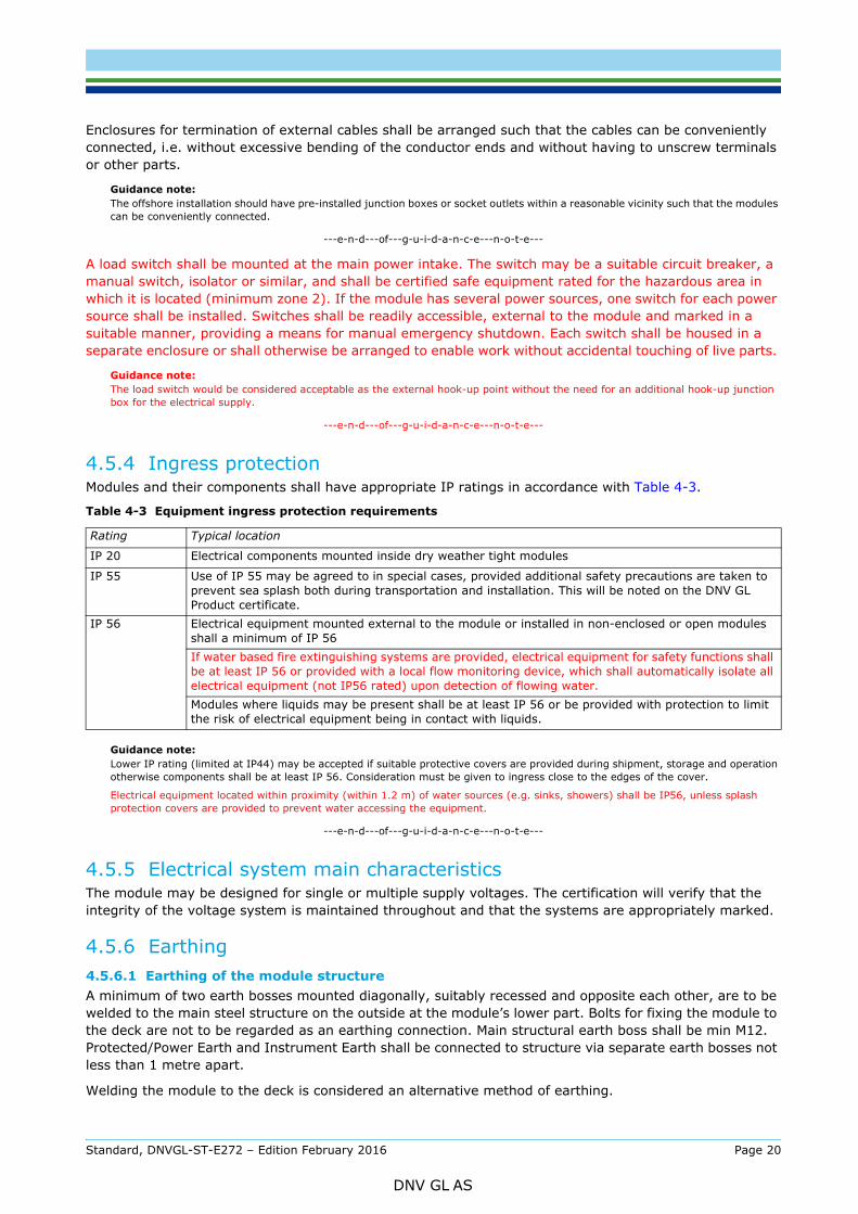
4.5.4 Ingress protectionModules and their components shall have appropriate IP ratings in accordance with Table 4-3.
Guidance note:Lower IP rating (limited at IP44) may be accepted if suitable protective covers are provided during shipment, storage and operation otherwise components shall be at least IP 56. Consideration must be given to ingress close to the edges of the cover.
Electrical equipment located within proximity (within 1.2 m) of water sources (e.g. sinks, showers) shall be IP56, unless splash protection covers are provided to prevent water accessing the equipment.
---e-n-d---of---g-u-i-d-a-n-c-e---n-o-t-e---
4.5.5 Electrical system main characteristicsThe module may be designed for single or multiple supply voltages. The certification will verify that the integrity of the voltage system is maintained throughout and that the systems are appropriately marked.
4.5.6 Earthing4.5.6.1 Earthing of the module structureA minimum of two earth bosses mounted diagonally, suitably recessed and opposite each other, are to be welded to the main steel structure on the outside at the module’s lower part. Bolts for fixing the module to the deck are not to be regarded as an earthing connection. Main structural earth boss shall be min M12. Protected/Power Earth and Instrument Earth shall be connected to structure via separate earth bosses not less than 1 metre apart.
Welding the module to the deck is considered an alternative method of earthing.
Table 4-3 Equipment ingress protection requirements
Rating Typical location
IP 20 Electrical components mounted inside dry weather tight modules
IP 55 Use of IP 55 may be agreed to in special cases, provided additional safety precautions are taken to prevent sea splash both during transportation and installation. This will be noted on the DNV GL Product certificate.
IP 56 Electrical equipment mounted external to the module or installed in non-enclosed or open modules shall a minimum of IP 56If water based fire extinguishing systems are provided, electrical equipment for safety functions shall be at least IP 56 or provided with a local flow monitoring device, which shall automatically isolate all electrical equipment (not IP56 rated) upon detection of flowing water.Modules where liquids may be present shall be at least IP 56 or be provided with protection to limit the risk of electrical equipment being in contact with liquids.
Standard, DNVGL-ST-E272 – Edition February 2016 Page 20
DNV GL AS
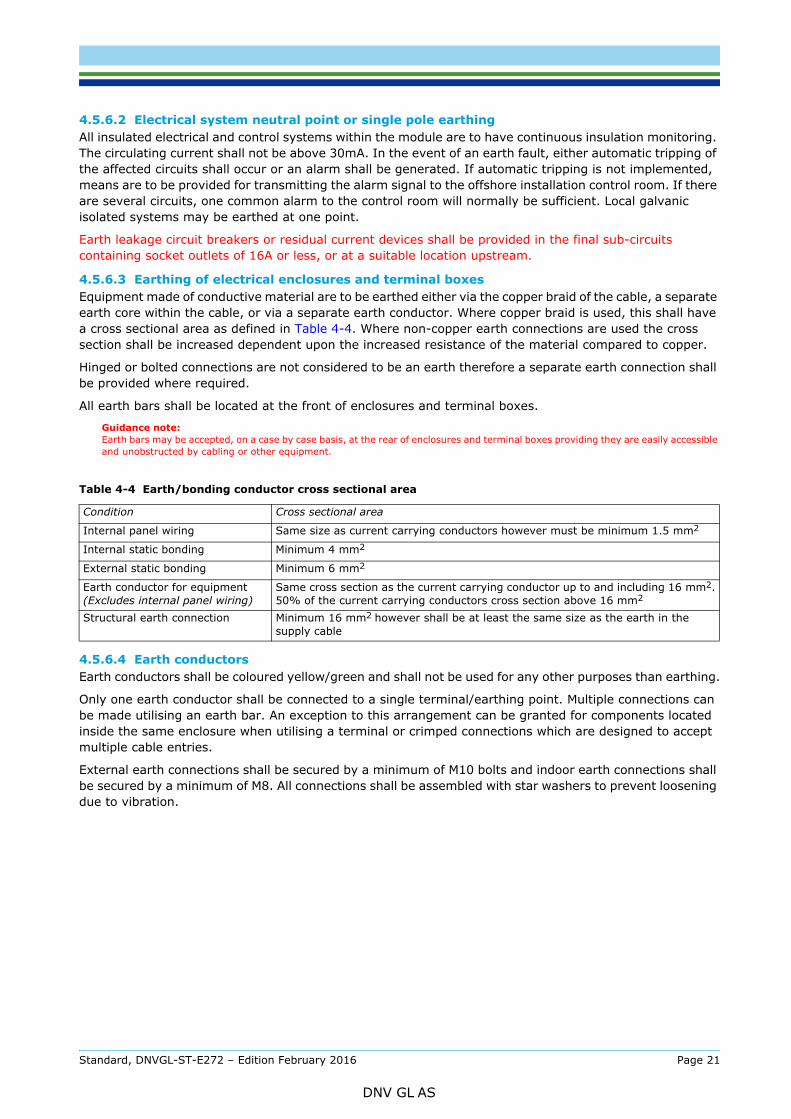
All insulated electrical and control systems within the module are to have continuous insulation monitoring. The circulating current shall not be above 30mA. In the event of an earth fault, either automatic tripping of the affected circuits shall occur or an alarm shall be generated. If automatic tripping is not implemented, means are to be provided for transmitting the alarm signal to the offshore installation control room. If there are several circuits, one common alarm to the control room will normally be sufficient. Local galvanic isolated systems may be earthed at one point.
Earth leakage circuit breakers or residual current devices shall be provided in the final sub-circuits containing socket outlets of 16A or less, or at a suitable location upstream.
4.5.6.3 Earthing of electrical enclosures and terminal boxesEquipment made of conductive material are to be earthed either via the copper braid of the cable, a separate earth core within the cable, or via a separate earth conductor. Where copper braid is used, this shall have a cross sectional area as defined in Table 4-4. Where non-copper earth connections are used the cross section shall be increased dependent upon the increased resistance of the material compared to copper.
Hinged or bolted connections are not considered to be an earth therefore a separate earth connection shall be provided where required.
All earth bars shall be located at the front of enclosures and terminal boxes.
Guidance note:Earth bars may be accepted, on a case by case basis, at the rear of enclosures and terminal boxes providing they are easily accessible and unobstructed by cabling or other equipment.
4.5.6.4 Earth conductorsEarth conductors shall be coloured yellow/green and shall not be used for any other purposes than earthing.
Only one earth conductor shall be connected to a single terminal/earthing point. Multiple connections can be made utilising an earth bar. An exception to this arrangement can be granted for components located inside the same enclosure when utilising a terminal or crimped connections which are designed to accept multiple cable entries.
External earth connections shall be secured by a minimum of M10 bolts and indoor earth connections shall be secured by a minimum of M8. All connections shall be assembled with star washers to prevent loosening due to vibration.
Table 4-4 Earth/bonding conductor cross sectional area
Condition Cross sectional area
Internal panel wiring Same size as current carrying conductors however must be minimum 1.5 mm2
Internal static bonding Minimum 4 mm2
External static bonding Minimum 6 mm2
Earth conductor for equipment (Excludes internal panel wiring)
Same cross section as the current carrying conductor up to and including 16 mm2.50% of the current carrying conductors cross section above 16 mm2
Structural earth connection Minimum 16 mm2 however shall be at least the same size as the earth in the supply cable
Standard, DNVGL-ST-E272 – Edition February 2016 Page 21
DNV GL AS
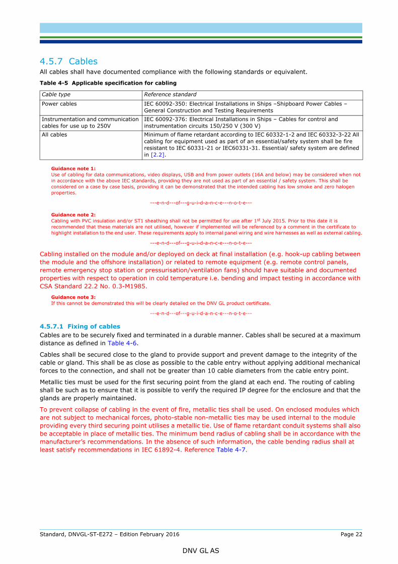
All cables shall have documented compliance with the following standards or equivalent.
Guidance note 1:Use of cabling for data communications, video displays, USB and from power outlets (16A and below) may be considered when not in accordance with the above IEC standards, providing they are not used as part of an essential / safety system. This shall be considered on a case by case basis, providing it can be demonstrated that the intended cabling has low smoke and zero halogen properties.
---e-n-d---of---g-u-i-d-a-n-c-e---n-o-t-e---
Guidance note 2:Cabling with PVC insulation and/or ST1 sheathing shall not be permitted for use after 1st July 2015. Prior to this date it is recommended that these materials are not utilised, however if implemented will be referenced by a comment in the certificate to highlight installation to the end user. These requirements apply to internal panel wiring and wire harnesses as well as external cabling.
---e-n-d---of---g-u-i-d-a-n-c-e---n-o-t-e---
Cabling installed on the module and/or deployed on deck at final installation (e.g. hook-up cabling between the module and the offshore installation) or related to remote equipment (e.g. remote control panels, remote emergency stop station or pressurisation/ventilation fans) should have suitable and documented properties with respect to operation in cold temperature i.e. bending and impact testing in accordance with CSA Standard 22.2 No. 0.3-M1985.
Guidance note 3:If this cannot be demonstrated this will be clearly detailed on the DNV GL product certificate.
---e-n-d---of---g-u-i-d-a-n-c-e---n-o-t-e---
4.5.7.1 Fixing of cablesCables are to be securely fixed and terminated in a durable manner. Cables shall be secured at a maximum distance as defined in Table 4-6.
Cables shall be secured close to the gland to provide support and prevent damage to the integrity of the cable or gland. This shall be as close as possible to the cable entry without applying additional mechanical forces to the connection, and shall not be greater than 10 cable diameters from the cable entry point.
Metallic ties must be used for the first securing point from the gland at each end. The routing of cabling shall be such as to ensure that it is possible to verify the required IP degree for the enclosure and that the glands are properly maintained.
To prevent collapse of cabling in the event of fire, metallic ties shall be used. On enclosed modules which are not subject to mechanical forces, photo-stable non-metallic ties may be used internal to the module providing every third securing point utilises a metallic tie. Use of flame retardant conduit systems shall also be acceptable in place of metallic ties. The minimum bend radius of cabling shall be in accordance with the manufacturer’s recommendations. In the absence of such information, the cable bending radius shall at least satisfy recommendations in IEC 61892-4. Reference Table 4-7.
Table 4-5 Applicable specification for cabling
Cable type Reference standard
Power cables IEC 60092-350: Electrical Installations in Ships –Shipboard Power Cables – General Construction and Testing Requirements
Instrumentation and communication cables for use up to 250V
IEC 60092-376: Electrical Installations in Ships – Cables for control and instrumentation circuits 150/250 V (300 V)
All cables Minimum of flame retardant according to IEC 60332-1-2 and IEC 60332-3-22 All cabling for equipment used as part of an essential/safety system shall be fire resistant to IEC 60331-21 or IEC60331-31. Essential/ safety system are defined in [2.2].
Standard, DNVGL-ST-E272 – Edition February 2016 Page 22
DNV GL AS
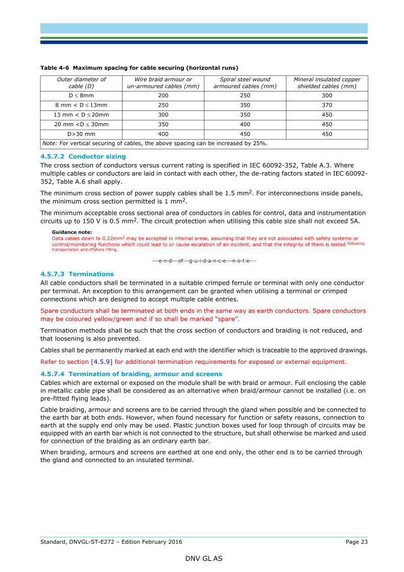
4.5.7.2 Conductor sizingThe cross section of conductors versus current rating is specified in IEC 60092-352, Table A.3. Where multiple cables or conductors are laid in contact with each other, the de-rating factors stated in IEC 60092-352, Table A.6 shall apply.
The minimum cross section of power supply cables shall be 1.5 mm2. For interconnections inside panels, the minimum cross section permitted is 1 mm2.
The minimum acceptable cross sectional area of conductors in cables for control, data and instrumentation circuits up to 150 V is 0.5 mm2. The circuit protection when utilising this cable size shall not exceed 5A.
Guidance note:Data cables down to 0.22mm2 may be accepted in internal areas, assuming that they are not associated with safety systems or control/monitoring functions which could lead to or cause escalation of an incident, and that the integrity of them is tested following transportation and offshore lifting..
---e-n-d---of---g-u-i-d-a-n-c-e---n-o-t-e---
4.5.7.3 TerminationsAll cable conductors shall be terminated in a suitable crimped ferrule or terminal with only one conductor per terminal. An exception to this arrangement can be granted when utilising a terminal or crimped connections which are designed to accept multiple cable entries.
Spare conductors shall be terminated at both ends in the same way as earth conductors. Spare conductors may be coloured yellow/green and if so shall be marked “spare”.
Termination methods shall be such that the cross section of conductors and braiding is not reduced, and that loosening is also prevented.
Cables shall be permanently marked at each end with the identifier which is traceable to the approved drawings.
Refer to section [4.5.9] for additional termination requirements for exposed or external equipment.
4.5.7.4 Termination of braiding, armour and screensCables which are external or exposed on the module shall be with braid or armour. Full enclosing the cable in metallic cable pipe shall be considered as an alternative when braid/armour cannot be installed (i.e. on pre-fitted flying leads).
Cable braiding, armour and screens are to be carried through the gland when possible and be connected to the earth bar at both ends. However, when found necessary for function or safety reasons, connection to earth at the supply end only may be used. Plastic junction boxes used for loop through of circuits may be equipped with an earth bar which is not connected to the structure, but shall otherwise be marked and used for connection of the braiding as an ordinary earth bar.
When braiding, armours and screens are earthed at one end only, the other end is to be carried through the gland and connected to an insulated terminal.
Table 4-6 Maximum spacing for cable securing (horizontal runs)
Outer diameter of cable (D)
Wire braid armour or un-armoured cables (mm)
Spiral steel wound armoured cables (mm)
Mineral insulated copper shielded cables (mm)
D ≤ 8mm 200 250 300
8 mm < D ≤ 13mm 250 350 370
13 mm < D ≤ 20mm 300 350 450
20 mm <D ≤ 30mm 350 400 450
D>30 mm 400 450 450
Note: For vertical securing of cables, the above spacing can be increased by 25%.
Standard, DNVGL-ST-E272 – Edition February 2016 Page 23
DNV GL AS
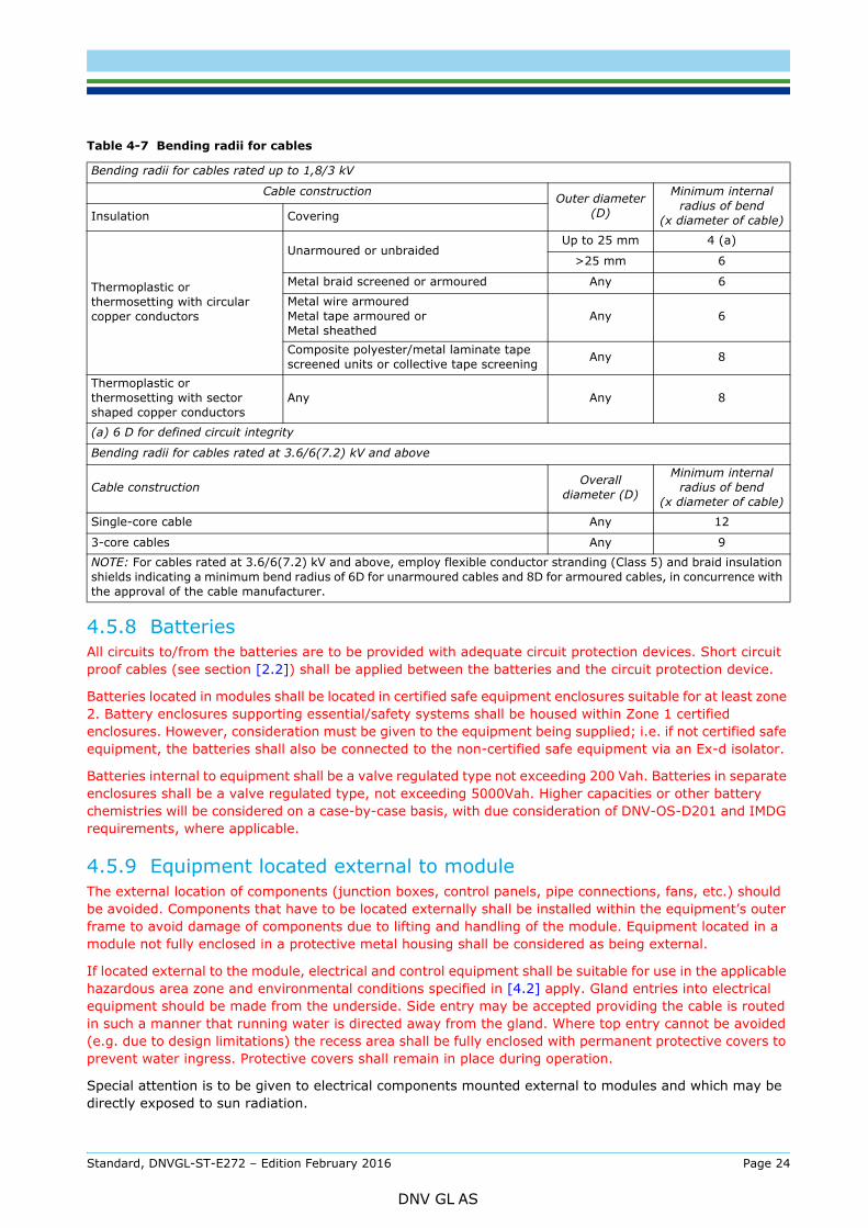
4.5.8 BatteriesAll circuits to/from the batteries are to be provided with adequate circuit protection devices. Short circuit proof cables (see section [2.2]) shall be applied between the batteries and the circuit protection device.
Batteries located in modules shall be located in certified safe equipment enclosures suitable for at least zone 2. Battery enclosures supporting essential/safety systems shall be housed within Zone 1 certified enclosures. However, consideration must be given to the equipment being supplied; i.e. if not certified safe equipment, the batteries shall also be connected to the non-certified safe equipment via an Ex-d isolator.
Batteries internal to equipment shall be a valve regulated type not exceeding 200 Vah. Batteries in separate enclosures shall be a valve regulated type, not exceeding 5000Vah. Higher capacities or other battery chemistries will be considered on a case-by-case basis, with due consideration of DNV-OS-D201 and IMDG requirements, where applicable.
4.5.9 Equipment located external to moduleThe external location of components (junction boxes, control panels, pipe connections, fans, etc.) should be avoided. Components that have to be located externally shall be installed within the equipment’s outer frame to avoid damage of components due to lifting and handling of the module. Equipment located in a module not fully enclosed in a protective metal housing shall be considered as being external.
If located external to the module, electrical and control equipment shall be suitable for use in the applicable hazardous area zone and environmental conditions specified in [4.2] apply. Gland entries into electrical equipment should be made from the underside. Side entry may be accepted providing the cable is routed in such a manner that running water is directed away from the gland. Where top entry cannot be avoided (e.g. due to design limitations) the recess area shall be fully enclosed with permanent protective covers to prevent water ingress. Protective covers shall remain in place during operation.
Special attention is to be given to electrical components mounted external to modules and which may be directly exposed to sun radiation.
Table 4-7 Bending radii for cables
Bending radii for cables rated up to 1,8/3 kV
Cable construction Outer diameter (D)
Minimum internal radius of bend
(x diameter of cable)Insulation Covering
Thermoplastic or thermosetting with circular copper conductors
Unarmoured or unbraidedUp to 25 mm 4 (a)
>25 mm 6
Metal braid screened or armoured Any 6
Metal wire armouredMetal tape armoured orMetal sheathed
Any 6
Composite polyester/metal laminate tape screened units or collective tape screening Any 8
Thermoplastic orthermosetting with sector shaped copper conductors
Any Any 8
(a) 6 D for defined circuit integrity
Bending radii for cables rated at 3.6/6(7.2) kV and above
Cable construction Overall diameter (D)
Minimum internal radius of bend
(x diameter of cable)
Single-core cable Any 12
3-core cables Any 9
NOTE: For cables rated at 3.6/6(7.2) kV and above, employ flexible conductor stranding (Class 5) and braid insulation shields indicating a minimum bend radius of 6D for unarmoured cables and 8D for armoured cables, in concurrence with the approval of the cable manufacturer.
Standard, DNVGL-ST-E272 – Edition February 2016 Page 24
DNV GL AS
not to have an external cooling fan unless the fan has been assessed as not being an ignition source and the overall equipment, including the fan, meets the ingress protection requirements.
4.5.10 Programmable controllers When programmable controllers (PLCs) are used for safety functions, they shall be of types suitable for the environmental conditions as given in [4.2].
Programmable controllers (including the specific firmware/software) which are used for safety functions shall be demonstrated as “fail safe”. The manufacturer shall be able to demonstrate the following fail safe conditions:
— failure of hardware— failure of input / output devices— failure of software / firmware— loss of electrical supply.
4.6 Ignition prevention
4.6.1 Requirements for electrical equipment exposed to hazardous atmospheres4.6.1.1 Certification of equipmentElectrical equipment for hazardous areas shall be designed, certified and categorised according to the IEC 60079 series publications or equivalent standards.
Guidance note:Independent certification issued to EN 60079 series having the same technical requirements as the IEC 60079 series are considered an acceptable equivalent however a comment will be included on the DNV GL product certificate highlighting acceptance of EN 60079 series as these standards may not recognised in all regions.
Use of self-declaration or voluntary certification is not considered equivalent to independent certification.
Where electrical equipment has been provided/ assessed in accordance with hazardous area equipment requirements for a specific region, certification may still be granted; however may detail limitations for the module with regard use on offshore installations which apply alternative requirements.
---e-n-d---of---g-u-i-d-a-n-c-e---n-o-t-e---
Independent certification shall be carried out by a notified body, competent body or other independent recognised institution.
If included as part of the marking or certificate number, the letter “X” denotes that special conditions have been defined for the safe use of the equipment. Special conditions that are dependent upon final offshore installation shall be listed in the DNV GL product certificate.
Guidance note:Certified safe equipment certificates may be invalidated by un-qualified repairs or modifications.
---e-n-d---of---g-u-i-d-a-n-c-e---n-o-t-e---
Optical sources are considered as electrical equipment and shall be certified in accordance with IEC 60079-28.
4.6.1.2 Non electrical equipment in hazardous areas.In addition to ignition risk from electrical equipment, assessments are required to ensure equipment does not present an ignition risk from mechanical (i.e. surface temperature, impact or friction), static discharge or lightening. Assessment for non-electrical ignition risk shall follow the requirements of IEC 80079 pt 36 and 37 or equivalent.
4.6.1.3 Inspection and installationSelection / installation of hazardous area equipment shall be in accordance with IEC 60079-14. An inspection plan shall be provided in accordance with IEC 60079-17. Records shall be retained to demonstrate that this inspection plan has been met during the life of the module. Operational manual shall include for need to conduct detailed inspection to IEC 60079-17 of any hook-up connections during installation.
Standard, DNVGL-ST-E272 – Edition February 2016 Page 25
DNV GL AS
request to the satisfaction of DNV GL.
4.7 Fire & gas detection
4.7.1 Gas detection and alarm system4.7.1.1 GeneralAll air inlets shall be fitted with a gas detector upstream of the fire or gastight damper unless all installations are of certified safe equipment and the use of tools or equipment in the area will not create any ignition potential. As a minimum, gas detection equipment shall be suitable for detection of methane (CH4) gas. If other flammable or toxic gases are considered likely additional detectors suitable for detection of these gases shall be provided at the intake and (if present) in the airlock (if installed).
In certain cases it may be necessary to interface the gas system in the module with the offshore installation. Details should be provided within the operational manual on required hook-up, operation and testing.
Non-enclosed modules with equipment containing a source of hydrocarbon release shall be fitted with a minimum of one gas detector. Where this is not possible special requirements shall be noted on the DNV GL Product Certificate detailing need for suitable gas detection to be provided by the offshore installation.
4.7.1.2 Gas detection inside the moduleGas detectors will be required inside the module if the following situations exist:
— At all ventilation outlets, if an internal source of release is present.— Inside module, if a source of release is present (e.g. paint stores, gas turbine enclosures, laboratory)
or if the module contains equipment which develops a hot surface. — Inside module, if disconnection of battery supplied equipment is delayed on loss of pressurisation.
Gas detection inside the module does not replace the need for gas detection at the air inlet. The air inlet, for ventilation, is the point within the non-hazardous area from which the air is drawn.
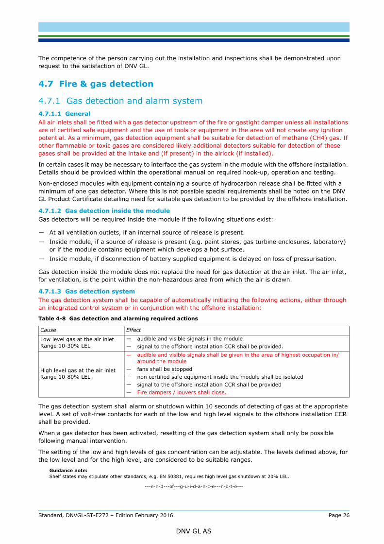
4.7.1.3 Gas detection systemThe gas detection system shall be capable of automatically initiating the following actions, either through an integrated control system or in conjunction with the offshore installation:
The gas detection system shall alarm or shutdown within 10 seconds of detecting of gas at the appropriate level. A set of volt-free contacts for each of the low and high level signals to the offshore installation CCR shall be provided.
When a gas detector has been activated, resetting of the gas detection system shall only be possible following manual intervention.
The setting of the low and high levels of gas concentration can be adjustable. The levels defined above, for the low level and for the high level, are considered to be suitable ranges.
Guidance note:Shelf states may stipulate other standards, e.g. EN 50381, requires high level gas shutdown at 20% LEL.
---e-n-d---of---g-u-i-d-a-n-c-e---n-o-t-e---
Table 4-8 Gas detection and alarming required actions
Cause Effect
Low level gas at the air inletRange 10-30% LEL
— audible and visible signals in the module— signal to the offshore installation CCR shall be provided.
High level gas at the air inletRange 10-80% LEL
— audible and visible signals shall be given in the area of highest occupation in/around the module
— fans shall be stopped — non certified safe equipment inside the module shall be isolated— signal to the offshore installation CCR shall be provided— Fire dampers / louvers shall close.
Standard, DNVGL-ST-E272 – Edition February 2016 Page 26
DNV GL AS
detector manufacturer.
The gas detection and alarm system shall be active at all times including during periods when power sources within the module are shut down. The local gas alarm station shall be connected to the same source used to supply the offshore installation fire & gas detection system or have a battery backed supply sufficient for 24-hour operation.
Guidance note:Should the gas detection system be powered from the offshore installation emergency switchboard the requirement for supply from the battery backed supply can be reduced to 2 hrs. However, the battery supply (transitional power) run time should be confirmed by as being of the same discharge duration as the offshore installation main F&G detection system (when running on battery/UPS supply).
---e-n-d---of---g-u-i-d-a-n-c-e---n-o-t-e---
Where facilities are provided for the by-pass of gas detection, these shall only be used for maintenance purposes onshore and shall not be utilised when on an offshore installation.
4.7.2 Fire detection and alarm system4.7.2.1 Fire detectors and alarmAt least one fire detector shall be located in each area of the module which presents a fire risk. This may be omitted in small airlocks which contain only minimal certified safe equipment or no combustible materials.
The type of detector shall be selected as the best suitable for early and reliable detection according to the actual fire risk.
The fire alarm system shall be designed and installed with certified safe equipment for operation in a zone 1 hazardous area regardless of intended location on the offshore installation.
4.7.2.2 Modules fitted with an integral fire alarm systemA fire alarm push button connected to the integral fire alarm system shall be mounted at a suitable place on a manned module and shall be marked “Fire alarm.”
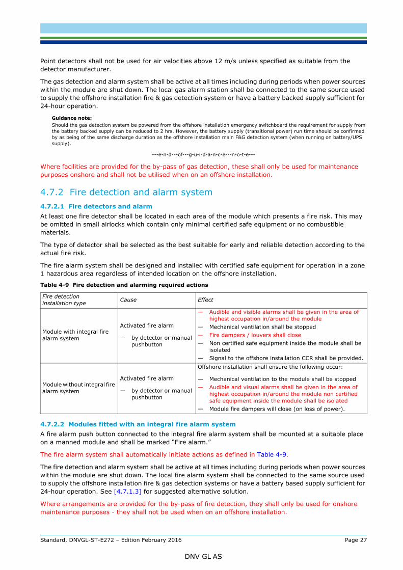
The fire alarm system shall automatically initiate actions as defined in Table 4-9.
The fire detection and alarm system shall be active at all times including during periods when power sources within the module are shut down. The local fire alarm system shall be connected to the same source used to supply the offshore installation fire & gas detection systems or have a battery based supply sufficient for 24-hour operation. See [4.7.1.3] for suggested alternative solution.
Where arrangements are provided for the by-pass of fire detection, they shall only be used for onshore maintenance purposes - they shall not be used when on an offshore installation.
Table 4-9 Fire detection and alarming required actions
Fire detection installation type Cause Effect
Module with integral fire alarm system
Activated fire alarm
— by detector or manual pushbutton
— Audible and visible alarms shall be given in the area of highest occupation in/around the module
— Mechanical ventilation shall be stopped — Fire dampers / louvers shall close— Non certified safe equipment inside the module shall be
isolated— Signal to the offshore installation CCR shall be provided.
Module without integral fire alarm system
Activated fire alarm
— by detector or manual pushbutton
Offshore installation shall ensure the following occur:
— Mechanical ventilation to the module shall be stopped — Audible and visual alarms shall be given in the area of
highest occupation in/around the module non certified safe equipment inside the module shall be isolated
— Module fire dampers will close (on loss of power).
Standard, DNVGL-ST-E272 – Edition February 2016 Page 27
DNV GL AS
The fire detector(s) may be connected directly to the offshore installation main fire detection system. In such cases, the module shall be arranged with suitable junction boxes for hook-up to the offshore installation system.
Mounting of appropriate types of detectors may be carried out as part of the installation on board.
A fire alarm push button shall be mounted at a suitable place on manned module and shall be marked “Fire alarm”. The push button shall be wired to a suitable junction box for connection to the offshore installation.
Upon the detection of fire actions described in accordance with Table 4-9 shall be automatically initiated by the offshore installation’s system.
4.7.3 Emergency shutdown initiated from offshore installationThe module shall be provided with a means to receive an ESD signal from the offshore installation to isolate all ignition sources. This may be conducted by tripping of supply to the module.
Equipment intended to stay energised after an offshore installation ESD signal shall be certified safe equipment for a zone 1 hazardous area.
4.8 Communications
4.8.1 Public address and general alarm system (PA/GA)Modules that are manned shall be fitted with loudspeaker(s) that can be connected to the offshore installation’s PA/GA system.
Guidance note:Unless stated otherwise in this standard a minimum of one PA/GA speaker shall be provided per module. However consideration should be given to offshore installations/vessels which have a dual PA/GA system and flexibility for inclusion of a second PA/GA speaker is recommended.
---e-n-d---of---g-u-i-d-a-n-c-e---n-o-t-e---
All equipment for public address and alarm systems shall be certified safe equipment for operation in zone 1 hazardous areas.
In modules with noise levels are above 85 dBA, the audible alarm shall be supplemented by light signals as per the offshore installation’s requirements.
Guidance note:The provision of additional PA/GA systems should be considered in unmanned modules containing equipment with noise levels exceeding 85dBA i.e. where the effectiveness of the offshore installations systems may be reduced.
---e-n-d---of---g-u-i-d-a-n-c-e---n-o-t-e---
4.8.2 Telephone / two way communicationAll manned modules shall have equipment suitable for effective two way communication with the offshore installation CCR.
Telephone systems, if installed, are to be connected via the module emergency shutdown system. Certified safe equipment circuits are to be used for those parts not being shut down. PA/GA Loudspeakers and telephones shall not share the same cable. Use of suitable rated portable radios shall also be considered acceptable for communication with the offshore installation CCR.
4.9 Fire fightingModules containing equipment considered to be a category ‘A’ machinery space or accommodation space (as defined by SOLAS) shall be fitted with a fixed fire-extinguishing system.
This document has considered the typical fire risk for each of the defined module groups and defines minimum requirements for fire fighting equipment in each case. (See [5.1]) When considering fire risk the categories detailed in Table 4-10 shall be utilised.
Standard, DNVGL-ST-E272 – Edition February 2016 Page 28
DNV GL AS
4.9.1 Portable extinguishersAt least one portable extinguisher shall be located inside of the module in an easily accessible position. For modules required to have several means of escape, one portable fire extinguisher shall be available near each exit (normally not required for emergency exits).
The type and quantity of extinguishing systems shall be in accordance with MSC.1/Circ 1275 and MODU code table 9.3.
Minimum capacities for each fire extinguisher shall be:
— 5 kg for CO2 or dry powder — 9 ltr or 9 Kg for foam or water based extinguishers.
4.9.2 Fixed extinguishing systemsAll fixed fire extinguishing systems shall comply with the provisions of the Fire Safety System code.
Manual release facility shall be located at an easily accessible position outside the module. It should have suitable protection against unintentional operation and shall be clearly marked.
Automatic release is recommended for modules containing high fire risk equipment. The automatic release mechanism may be, e.g., a direct temperature sensitive device or may be operated by a signal from the fire detection system. Fire-extinguishing systems which have a gaseous fire-fighting medium shall be manually activated only.
Should the fire-extinguishing medium be a gaseous type harmful to personnel the system shall be designed according to DNV OS D301 Appendix A Section C and shall not be within the protected space. Where the fire suppression medium contains an equivalent fixed gas fire-fighting system (e.g. gaseous system which is non-harmful and certified in accordance with FSS code) this can be considered within the protected space providing the requirements of IMO MSC/Circ. 848(as amended by 1267) Item 11 are satisfied.
Water based systems shall have automatic activation only.
Guidance note:In order to make the system more resistant to false alarms, it is recommended that two or more fire detectors be used, and that the design logic be such that activation of one detector only will not release the system, but will give an alarm only.
---e-n-d---of---g-u-i-d-a-n-c-e---n-o-t-e---
Control circuits for the fire extinguishing system release and corresponding alarms shall be active continuously, including periods when other power sources within the module are shut down. The system shall utilise certified safe equipment for operation in a zone 1 hazardous area regardless of intended location on the offshore installation and shall be connected to the same source used to supply the offshore installation fire & gas detection systems or have a battery backed supply sufficient for 24-hour operation. See [4.7.1.3] for suggested alternative solution.
Table 4-10 Categorisation of fire risk
Categorisation Definition
No fire risk Modules containing no energy sources (i.e. electrical, chemical or mechanical)
Low fire riskModule for storage of non-flammable equipment such as tools, mechanical parts and electrical equipment not connected to power. The module itself contains only a minimum of necessary electrical equipment for lighting, heating, etc. A fire is not likely to be supported.
Medium fire risk Modules containing electrical panels, testing equipment, work space for paper work. Modules which are normally manned (not accommodation modules).
High fire risk Modules containing category ‘A’ machinery spaces, accommodation modules and stores for flammable liquids. Also high power electrical machinery.
Standard, DNVGL-ST-E272 – Edition February 2016 Page 29
DNV GL AS
4.10 Passive fire protection
4.10.1 GeneralThe objectives of passive fire protection (PFP) are to prevent or mitigate the serious consequences from a fire, such as to:
— prevent escalation of fire from one area to an adjacent area— protect personnel from the fire (heat and smoke) and make escape or evacuation possible— protect systems and equipment of essential importance for safety.
Materials to be used for the purpose of passive fire protection shall be supplied with an approval certificate documenting compliance with an appropriate Fire resistant test code; e.g. FTP Code. Detailed information supporting the certificates showing required construction methods and limitations shall also be available.
Heat transmissions at intersections and termination points of required thermal barriers in fire rated divisions shall be specially considered.
Guidance note 1:Any such heat bridge should be insulated to the same rating as the thermal barrier for a distance of not less than 900 mm, typically 450 mm on each side.
---e-n-d---of---g-u-i-d-a-n-c-e---n-o-t-e---
Openings and penetrations in fire-rated divisions shall be arranged so as to maintain the fire rating of the divisions. Penetrations shall be of an approved type for the fire rating of the divisions where they are to be installed. Louvers / dampers shall be operable from outside the module and configured for automatic closure on fire detection as well as manual closure. Louvers / dampers for external ventilation openings shall be provide through external bulkheads. The louver / damper does not require to be ‘A’ rated when passing through an external ‘A’ rated bulkhead. Conductive materials in contact with external bulkheads are considered part of the bulkhead and shall meet the requirements of the division. The extent of the insulation shall be sufficient to cover all exposed thermally conductive surfaces fitted to the bulkhead for a distance of at least 900 mm; however ducting does not require to be 900 mm if not required by the design of the module or contains non thermally conductive materials. Alternative insulation length in accordance with ‘A’ certified materials/equipment can be accepted upon confirmation of insulation lengths in accordance with the certificate.
Guidance note 2:Refer to SOLAS Ch II-2 Reg 9 for details on internal ducting and cable/pipe penetrations through fire rated bulkheads.
---e-n-d---of---g-u-i-d-a-n-c-e---n-o-t-e---
For equipment located on open deck a continuous steel construction is required to satisfy SOLAS / MODU code fire rating divisions. For certain applications (e.g. winches / lifting equipment) this may not be possible or practical to enclose the module. The use of modules which do not satisfy continuous steel construction may be permitted, however to meet the intent of SOLAS / MODU code requirements the end user shall be responsible for detecting and reacting to a fire event on the module prior to it spreading to deck. This will be clearly defined in the DNV GL Product Certificate.
Guidance note 3:Modules not meeting the minimum fire rating divisions as specified in SOLAS / MODU code shall be considered when the function of the equipment necessitates the need for an opening in the fire rated division. Where it is possible to enclose the module to meet the
Table 4-11 Required actions following release of fixed fire system
Cause Effect
Activated fixed fire fighting installation
— Automatic or manual
— Audible release alarm activated inside module, signal shall be different and distinguishable from other signals
— Mechanical ventilation shall be stopped — Fire dampers/ louvers/closing device will close— Confirmed release alarm to offshore installation control room— Non certified safe equipment inside the module shall be isolated
Standard, DNVGL-ST-E272 – Edition February 2016 Page 30
DNV GL AS
under table 4.10 as high fire risk shall always meet the minimum fire rating.
---e-n-d---of---g-u-i-d-a-n-c-e---n-o-t-e---
4.10.2 Restricted use of combustible materialsExposed surfaces in ceilings or any surfaces in concealed or inaccessible spaces for accommodation, service spaces and control stations shall have documented low flame-spread characteristics according to the IMO FTP Code Parts 2.
Primary deck coverings shall not readily ignite or give rise to toxic or explosive hazards at elevated temperatures in accordance with the IMO FTP Code Part 5.
Paint / surface coatings applied internally or externally shall meet the requirements for primary deck coverings.
4.11 Escape
4.11.1 DoorsA personnel door shall be fitted where users are expected to enter the equipment including for planned maintenance. All personnel access doors shall be self-closing. Container doors are not considered personnel doors unless they are fitted with a self-closing device and are capable of latching into a closed position.
Modules with mechanical ventilation containing ignition sources shall have self-closing doors. All other hatches and doors shall be closed when the module is energised.
All external doors shall open outwards.
The self-closing mechanism is to be capable of closing the door with an over- pressure ventilation system in operation. This requirement does not apply to transport doors or emergency exits. Doors fitted with self-closing mechanisms shall not be fitted with latching mechanisms to hold the door open.
Guidance note:This requirement supersedes the requirements within DNV 2.7-1 for doors to be able to be latched in the open position.
---e-n-d---of---g-u-i-d-a-n-c-e---n-o-t-e---
Where necessary to prevent unauthorised access, doors may be fitted with a lock. In such cases provision shall be made for safe egress from inside without a key.
Modules which present additional danger if locked in, e.g. air tight modules or refrigeration/freezer modules, an alarm shall be provided to raise attention of personnel trapped within the module. The alarm shall be supplied from an emergency source of power from the offshore installation or provided with a battery back-up should main power be lost. The alarm shall provide a visual and audible warning external to the module when activated.
4.11.2 Emergency exits and escape routesModules that are manned, and either have an internal area exceeding 20 m2 or the escape route length to the external exit door exceeds 5 m, shall have a separate emergency exit. Any separate emergency exit shall be located in an easily accessible position and as widely spaced from the main exit as possible. Escape hatches shall have a minimum size of 800 mm x 800 mm and be possible to open from both sides by one person. Clearance shall be provided within the module to allow for manoeuvre of a stretcher through the emergency exit. Consideration shall be given to the arrangement and position of the emergency escape with regard to ease of access and distance to deck when egressing though the exit. Any considerations for the user shall be specified in the operational manual and if necessary marked on the emergency exit.
An unobstructed route (minimum 650 mm wide) shall be provided between areas where personnel access may be possible and emergency exits. The module design shall consider sufficient height for ease of egress to the escape exits / hatches.
Escape exits shall be marked with photo luminescent material on both sides with the words “EMERGENCY EXIT” and “NOT TO BE OBSTRUCTED”.
Standard, DNVGL-ST-E272 – Edition February 2016 Page 31
DNV GL AS
Manned modules shall be fitted with emergency lighting which shall be certified safe equipment to zone 1 requirements and fitting with integral battery sufficient for at least 60 minutes operation.
At least one emergency light shall be installed in each room of the module where persons may be present.
Battery backed emergency lighting shall be fitted above main and emergency exits. Where an airlock or two entry doors are utilised, the emergency lighting can be positioned either in the airlock/entrance space or above the internal door within the main room, providing the internal door is provided with a vision panel.
Emergency lighting may be omitted in secondary rooms if there is no closable door and no part of the floor is more than 2 m from the main room.
Guidance note:Appropriate procedures or some automatic means is to be implemented to ensure that the emergency lighting battery is readily available and fully charged when the module is taken into operation.
---e-n-d---of---g-u-i-d-a-n-c-e---n-o-t-e---
4.12 Heating, ventilation and air conditioning
4.12.1 Air inlets/ outletsAll air inlets shall be fitted with a gas detector before the fire or gastight damper unless all equipment installed in the module is certified safe equipment and the use of tools or equipment in the area will not create any ignition sources.
Closure mechanisms shall be fail safe, i.e. de-energise to close. Simultaneous stop of all ventilation fans should be possible by manual activation of one handle, push button or similar control.
This manual facility may also isolate and/or initiate other functions, e.g., module shutdown/ electrical isolation.
The position of dampers/louvers shall be visible locally at the damper and to the offshore installation’s ventilation control system/CCR.
The inlet and outlet openings shall be arranged for connection of ducts which can be routed for a fresh air supply/exhaust from/to a non-hazardous area. Modules incorporating over pressure ventilation systems shall be arranged to allow location of the fan at the inlet end of the duct in the non-hazardous area, thus keeping the duct at an over-pressure relative to the surroundings.
If a fire risk exists inside the module all ventilation openings, including louvers shall have facilities to be closed from outside the module.
4.12.2 Natural ventilationNatural ventilation may be applied for modules intended only for storage of non-hazardous/non-flammable materials and which are not manned.
The module shall be provided with suitable ventilation openings, located at the top and bottom of the bulkheads.
If the module is designed as an open skid or frame, a ventilation system is not necessary however reference is made to section [4.10.1].
4.12.3 Mechanical ventilationThe requirements for heating and ventilation systems for offshore containers are based on the following:
— Personnel shall have sufficient fresh air and comfortable working temperatures.
— Ventilation may be used to keep the atmosphere free from explosive gasses and vapours. If the source of hazard is outside the container, the applicable means of ensuring this is to apply internal over-pressure with respect to the external environment.
Standard, DNVGL-ST-E272 – Edition February 2016 Page 32
DNV GL AS
The statutory regulations may require a ventilation rate of minimum 12 litres per second of fresh air per person.
---e-n-d---of---g-u-i-d-a-n-c-e---n-o-t-e---
The following modules require mechanical ventilation:
a) Modules in which ignition sources are present.b) Modules that are manned (For requirements for fresh air refer to [4.12.3.1]). c) Modules in which equipment emits large amounts of heat.d) Modules with an internal source of release.
The flow of ventilation air shall be continuously monitored. During operation upon the detection of inadequate ventilation, a local alarm shall be initiated within a safe period of time unless the supply is automatically restored from alternative fans or any alternative power supply. It is recommended that this safe period should be less than 15 minutes however maximum time shall not exceed the value based on the following calculation:
Time (minutes) = Free volume of module (m3)/ (0.72 × number of occupants)
Where arrangements are provided for the by-pass of ventilation/pressurisation facilities, they shall only be used for onshore maintenance purposes and shall not be utilised on an offshore installation.
4.12.3.1 Manned areas (heating and air condition)For modules which are manned, sufficient heating and/or cooling is to be provided to ensure comfort. The system is to be designed such that the inlet air is not distributed to the work places unless it is conditioned (hot / cold / humidity).
The minimum required ventilation rate for working areas is 12 l/s of outside air per person. The module shall be marked with the maximum occupancy.
4.12.3.2 Cooling of equipmentOutside air intended for cooling of non-certified equipment shall not be fed directly onto the equipment being cooled. The air should instead be fed into the module in order to allow for the response time of gas detection systems.
4.12.3.3 Heating elements and air fansHeating elements (including heating elements within space heaters, water heaters and ovens) and air fans located in the inlet air duct shall be of certified safe type. This also applies to space heaters for modules intended for location in zone 1 hazardous areas. The fan blades are to be non-sparking and shall have suitable protection against mechanical damage.
Guidance note:Fans for ventilation may be accepted when not of a certified safe type when located in a non-hazardous area and gas detection is provided locally on the fan assembly. Demonstration of no residual ignition risks (e.g. dissimilar metals in fan blades or gap between blades and housing to prevent sparks when fan is slowing) shall be required.
---e-n-d---of---g-u-i-d-a-n-c-e---n-o-t-e---
For modules intended for location in zone 2 and non-hazardous areas, non-certified safe space heaters may be used provided the exposed temperatures have been tested and confirmed to be below 200°C and suitable assessment of ignition risk has been demonstrated.
Heaters are to be interlocked with the ventilation fan switch or a flow switch such that they cannot be energised unless the fan is running
Heaters are to have at least one safety temperature sensor in addition to the normal service working temperature regulating devices and shall be in contact with the heating element to accurately determine the temperature of the surface.
Guidance note:For testing of the maximum temperature, the test voltage should be 110%. Where relevant, the temperature rise shall be included after a built-in fan has stopped. The temperature is to be measured directly on the heating elements. If the elements are encapsulated in metal pipes or similar, which are gas tight also at the ends, the temperature may be measured on the pipes.
The following combinations of materials and clearances between impeller and duct are considered to be non-sparking:
— impellers and/or housing of non-metallic material, due regard being paid to the elimination of static electricity
Standard, DNVGL-ST-E272 – Edition February 2016 Page 33
DNV GL AS
— impellers of aluminium alloys or magnesium alloys and a ferrous (including austenitic stainless steel) housing on which a ring of suitable thickness of non- ferrous materials is fitted, due regard being paid to static electricity and corrosion between ring and housing
— impellers and housing of austenitic stainless steel— any combination of ferrous (including austenitic stainless steel) impellers and housing with not less than a 13 mm tip design
clearance.
Any combination of an aluminium or magnesium alloy fixed or rotating component, and a ferrous fixed or rotating component, regardless of tip clearance, is considered a spark hazard and is not to be used.
---e-n-d---of---g-u-i-d-a-n-c-e---n-o-t-e---
4.12.4 Over-pressurised ventilation systemsModules with ignition sources (e.g., non-certified hazardous area equipment) located in a hazardous area shall have over-pressure with monitoring. The value of the overpressure inside a module shall be kept above 50 Pa but shall not exceed 200 Pa.
Guidance note:It should be noted that for pressurised modules built within EU/EEA countries this standard has not been fully aligned with the essential health and safety requirements of EN 50381. Where requirements differ between EN 50381 and DNV 2.7-2 guidance notes have been inserted. When pressurised equipment is intended for use in an EU/EEA member country it is recommended for the client to specify additional review to EN 50381 allowing this to be incorporated within the Offshore Service Module Certificate.
---e-n-d---of---g-u-i-d-a-n-c-e---n-o-t-e---
Boundary doors shall be self-closing and gas-tight.
Enclosed spaces (e.g., panels, cupboards, cable ducting) shall not exceed 10% of the volume of the module without being provided with additional means of ventilation e.g. louvers. If an internal source of release exists in these enclosed spaces they shall be provided with additional ventilation regardless of volume.
An automatic system for control of the purging shall be implemented. The necessary time for purging shall be established based on tests and measurements of air flow on the built module.
A pressure drop for a limited period of 30 seconds during the purge phase may be acceptable. If the pressure drops for more than 30 seconds, the purge cycle should be automatically restarted.
Regardless of safe area or hazardous location, a purge cycle of minimum 6 air changes is to be performed before non-hazardous area certified equipment inside the module is energised. Calculation of purge time shall be based upon set point of minimum air flow during purge and not nominal air flow.
Guidance note:Shelf states may stipulate other requirements, e.g., EN 50381 which requires a minimum of ten or five volumetric air changes per hour for zone 1 and zone 2 hazardous areas respectively, and that air changes shall be doubled unless representative gas testing is conducted.
---e-n-d---of---g-u-i-d-a-n-c-e---n-o-t-e---
Failure of over-pressure ventilation shall be alarmed at a manned location (local and remote). A pre-set time delay of up to 30 seconds may be applied to minimise spurious alarms when doors are intentionally opened.
Guidance note:Shelf states may stipulate other requirements, e.g., EN 50381, which requires instantaneous shutdown of zone 1 modules or modules with an internal source of release unless an external door switch is fitted indicating the door has been left open.
An allowable delay time of 30 seconds for opening the module door has proved to be a practical compromise and has been commonly used.
On loss of over-pressure, isolation of the batteries may be delayed for up to 10 minutes. This requires an internal gas detector to be fitted for immediate isolation of batteries on gas detection.
---e-n-d---of---g-u-i-d-a-n-c-e---n-o-t-e---
Ignition sources shall be isolated where ventilation cannot be restored within a short time, typically within 30 seconds and at a maximum 90 seconds, or if gas is detected within the area during ventilation failure.
The following automatic actions shall then be initiated:
— All electrical equipment inside the module which is not certified safe equipment for the corresponding outside hazardous area shall be isolated.
Standard, DNVGL-ST-E272 – Edition February 2016 Page 34
DNV GL AS
— A loss of pressurisation alarm is initiated to the offshore installation control room.
Guidance note:Shelf states may stipulate other requirements, e.g., EN 50381, which requires shutdown of inlet and extract dampers upon the occurrence of ventilation failure and/or loss of pressurisation.
---e-n-d---of---g-u-i-d-a-n-c-e---n-o-t-e---
The switch for isolating non-certified equipment for the above shall be certified safe equipment for use in a hazardous area.
An indicating instrument showing the actual differential pressure relative to atmosphere shall be installed within the module.
4.12.4.1 Air locksModules for use in zone 1 which contain ignition sources shall have overpressure ventilation and an air lock. In an air lock, the inner door should open into the module. (i.e. both doors open away from the airlock)
Guidance note:Arrangements where the inner door of the airlock opens into the airlock shall also be considered providing there is sufficient space for the internal door to be closed prior to the external door being opened.
---e-n-d---of---g-u-i-d-a-n-c-e---n-o-t-e---
Air locks shall consist of gas tight bulkheads and gas tight self-closing doors. The air lock shall be mechanically ventilated at a positive pressure against the adjacent hazardous area or outside atmosphere, and the air lock shall at a minimum be classified zone 2.
Where the airlock is gas tight use of a gas detector within the airlock in place of mechanical ventilation shall also be accepted. Gas detector shall be set to shutdown module at 25% LEL.
There are no requirements for an air lock in modules placed in non-hazardous and zone 2 areas. However, where an inner door is installed suitable purging of the space between the external door and the internal door shall be demonstrated in order to ensure that the accumulation of hazardous atmospheres cannot occur.
Guidance note 1:Modules with internal and external doors with the space between not fitted with mechanical ventilation a control procedure shall be implemented to ensure that the internal door is open prior to purging commencing.
---e-n-d---of---g-u-i-d-a-n-c-e---n-o-t-e---
Guidance note 2:For modules intended for use in areas classified as zone 2, additional requirements may be applicable when also complying with requirements of IEC 60079-13 with regard to maintaining minimum pressure / air flow with external door open.
---e-n-d---of---g-u-i-d-a-n-c-e---n-o-t-e---
4.12.4.2 Non certified safe equipment in pressurised modulesTo ensure full isolation of ignition sources within the module the following shall be applied:
— No battery operated devices (e.g. laptops, data recorders etc.) unless batteries are removed and adequately stored to prevent short circuit.
— No fibre optic equipment other than that specified in the design assessment shall be added.— No signal (including data) or power connection are to be brought directly into the module unless they
are intrinsically safe, as this will cause an ignition source to be present in a hazardous area following any shutdown of the pressurisation system with the exception of signals specified within the hook-up requirements in the design assessment / DNV GL product certificate.
— Exposed surface temperatures on equipment shall be assessed and confirmed to be below 200°C (e.g. ovens, heaters, display monitors, computers, etc.). For zone 1 application, two levels of safety shutdown device, in addition to normal operational controls/thermostat, must be provided.
The above requirements are to be included in the modules operational manual to highlight the need for the end user to comply with the above when adding or using equipment within an approved module.
Standard, DNVGL-ST-E272 – Edition February 2016 Page 35
DNV GL AS
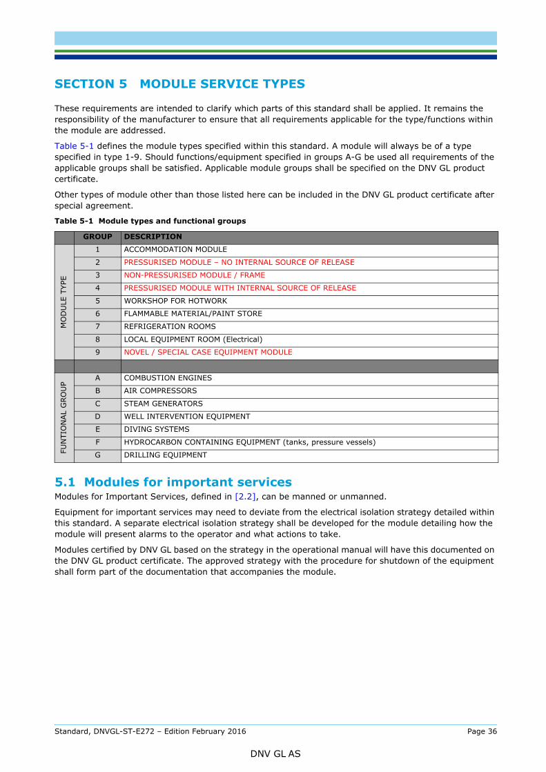
These requirements are intended to clarify which parts of this standard shall be applied. It remains the responsibility of the manufacturer to ensure that all requirements applicable for the type/functions within the module are addressed.
Table 5-1 defines the module types specified within this standard. A module will always be of a type specified in type 1-9. Should functions/equipment specified in groups A-G be used all requirements of the applicable groups shall be satisfied. Applicable module groups shall be specified on the DNV GL product certificate.
Other types of module other than those listed here can be included in the DNV GL product certificate after special agreement.
5.1 Modules for important servicesModules for Important Services, defined in [2.2], can be manned or unmanned.
Equipment for important services may need to deviate from the electrical isolation strategy detailed within this standard. A separate electrical isolation strategy shall be developed for the module detailing how the module will present alarms to the operator and what actions to take.
Modules certified by DNV GL based on the strategy in the operational manual will have this documented on the DNV GL product certificate. The approved strategy with the procedure for shutdown of the equipment shall form part of the documentation that accompanies the module.
Table 5-1 Module types and functional groups
GROUP DESCRIPTION
MO
DU
LE T
YPE
1 ACCOMMODATION MODULE
2 PRESSURISED MODULE – NO INTERNAL SOURCE OF RELEASE
3 NON-PRESSURISED MODULE / FRAME
4 PRESSURISED MODULE WITH INTERNAL SOURCE OF RELEASE
5 WORKSHOP FOR HOTWORK
6 FLAMMABLE MATERIAL/PAINT STORE
7 REFRIGERATION ROOMS
8 LOCAL EQUIPMENT ROOM (Electrical)
9 NOVEL / SPECIAL CASE EQUIPMENT MODULE
FUN
TIO
NAL
GRO
UP
A COMBUSTION ENGINES
B AIR COMPRESSORS
C STEAM GENERATORS
D WELL INTERVENTION EQUIPMENT
E DIVING SYSTEMS
F HYDROCARBON CONTAINING EQUIPMENT (tanks, pressure vessels)
G DRILLING EQUIPMENT
Standard, DNVGL-ST-E272 – Edition February 2016 Page 36
DNV GL AS
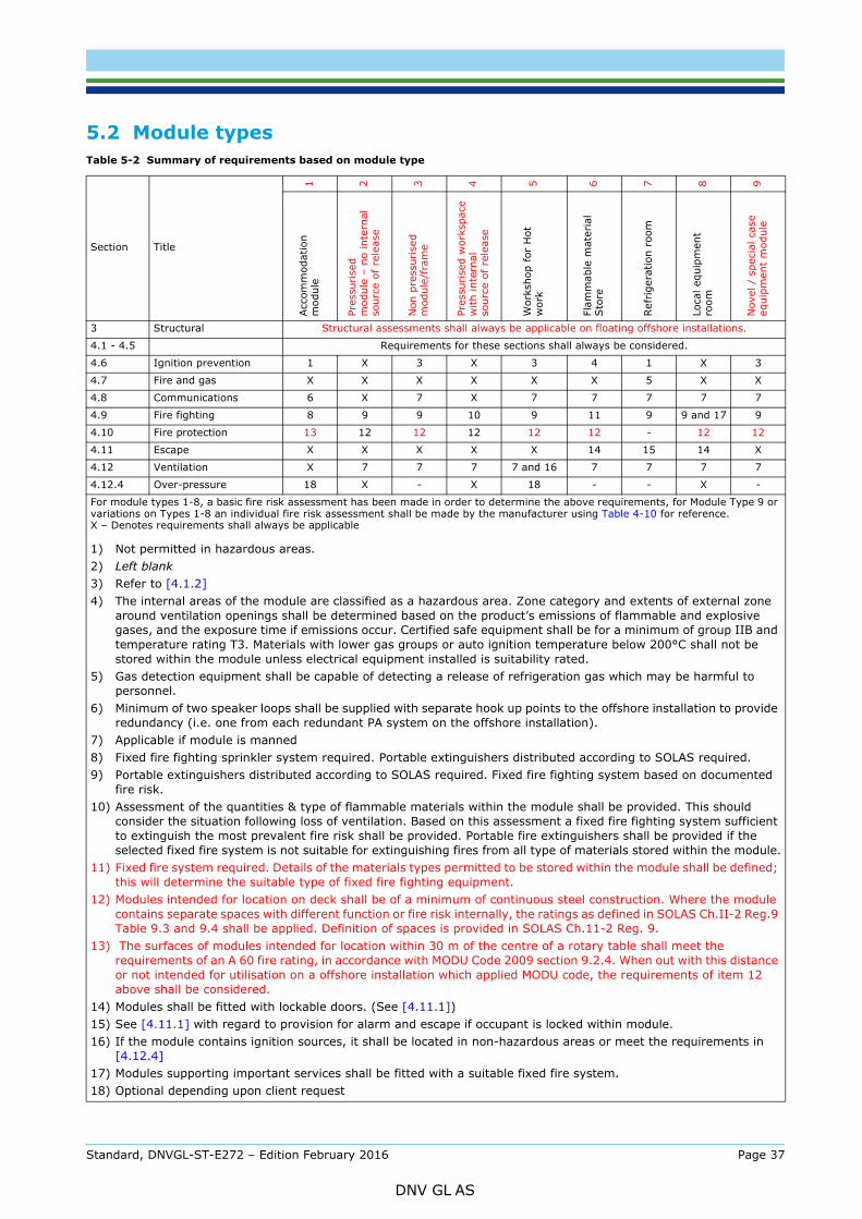
Table 5-2 Summary of requirements based on module type
Section Title
1 2 3 4 5 6 7 8 9
Acc
omm
odat
ion
mod
ule
Pres
suri
sed
mod
ule
– no
inte
rnal
so
urce
of
rele
ase
Non
pre
ssur
ised
m
odul
e/fr
ame
Pres
suri
sed
wor
kspa
ce
with
inte
rnal
so
urce
of
rele
ase
Wor
ksho
p fo
r H
ot
wor
k
Flam
mab
le m
ater
ial
Sto
re
Ref
rige
ratio
n ro
om
Loca
l equ
ipm
ent
room
Nov
el /
spe
cial
cas
eeq
uipm
ent
mod
ule
3 Structural Structural assessments shall always be applicable on floating offshore installations.
4.1 - 4.5 Requirements for these sections shall always be considered.
4.6 Ignition prevention 1 X 3 X 3 4 1 X 3
4.7 Fire and gas X X X X X X 5 X X
4.8 Communications 6 X 7 X 7 7 7 7 7
4.9 Fire fighting 8 9 9 10 9 11 9 9 and 17 9
4.10 Fire protection 13 12 12 12 12 12 - 12 12
4.11 Escape X X X X X 14 15 14 X
4.12 Ventilation X 7 7 7 7 and 16 7 7 7 7
4.12.4 Over-pressure 18 X - X 18 - - X -
For module types 1-8, a basic fire risk assessment has been made in order to determine the above requirements, for Module Type 9 or variations on Types 1-8 an individual fire risk assessment shall be made by the manufacturer using Table 4-10 for reference. X – Denotes requirements shall always be applicable
1) Not permitted in hazardous areas.2) Left blank3) Refer to [4.1.2]4) The internal areas of the module are classified as a hazardous area. Zone category and extents of external zone
around ventilation openings shall be determined based on the product’s emissions of flammable and explosive gases, and the exposure time if emissions occur. Certified safe equipment shall be for a minimum of group IIB and temperature rating T3. Materials with lower gas groups or auto ignition temperature below 200°C shall not be stored within the module unless electrical equipment installed is suitability rated.
5) Gas detection equipment shall be capable of detecting a release of refrigeration gas which may be harmful to personnel.
6) Minimum of two speaker loops shall be supplied with separate hook up points to the offshore installation to provide redundancy (i.e. one from each redundant PA system on the offshore installation).
7) Applicable if module is manned8) Fixed fire fighting sprinkler system required. Portable extinguishers distributed according to SOLAS required.9) Portable extinguishers distributed according to SOLAS required. Fixed fire fighting system based on documented
fire risk.10) Assessment of the quantities & type of flammable materials within the module shall be provided. This should
consider the situation following loss of ventilation. Based on this assessment a fixed fire fighting system sufficient to extinguish the most prevalent fire risk shall be provided. Portable fire extinguishers shall be provided if the selected fixed fire system is not suitable for extinguishing fires from all type of materials stored within the module.
11) Fixed fire system required. Details of the materials types permitted to be stored within the module shall be defined; this will determine the suitable type of fixed fire fighting equipment.
12) Modules intended for location on deck shall be of a minimum of continuous steel construction. Where the module contains separate spaces with different function or fire risk internally, the ratings as defined in SOLAS Ch.II-2 Reg.9 Table 9.3 and 9.4 shall be applied. Definition of spaces is provided in SOLAS Ch.11-2 Reg. 9.
13) The surfaces of modules intended for location within 30 m of the centre of a rotary table shall meet the requirements of an A 60 fire rating, in accordance with MODU Code 2009 section 9.2.4. When out with this distance or not intended for utilisation on a offshore installation which applied MODU code, the requirements of item 12 above shall be considered.
14) Modules shall be fitted with lockable doors. (See [4.11.1])15) See [4.11.1] with regard to provision for alarm and escape if occupant is locked within module.16) If the module contains ignition sources, it shall be located in non-hazardous areas or meet the requirements in
[4.12.4]17) Modules supporting important services shall be fitted with a suitable fixed fire system. 18) Optional depending upon client request
Standard, DNVGL-ST-E272 – Edition February 2016 Page 37
DNV GL AS
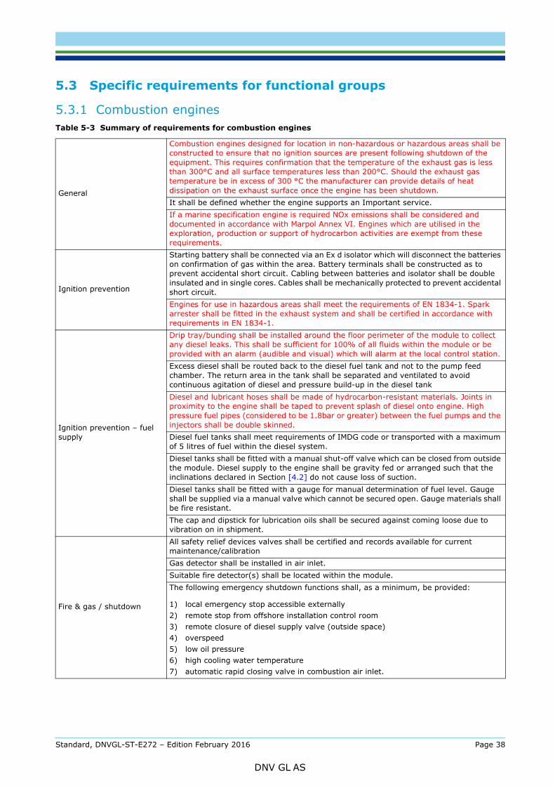
5.3.1 Combustion enginesTable 5-3 Summary of requirements for combustion engines
General
Combustion engines designed for location in non-hazardous or hazardous areas shall be constructed to ensure that no ignition sources are present following shutdown of the equipment. This requires confirmation that the temperature of the exhaust gas is less than 300°C and all surface temperatures less than 200°C. Should the exhaust gas temperature be in excess of 300 °C the manufacturer can provide details of heat dissipation on the exhaust surface once the engine has been shutdown.It shall be defined whether the engine supports an Important service.If a marine specification engine is required NOx emissions shall be considered and documented in accordance with Marpol Annex VI. Engines which are utilised in the exploration, production or support of hydrocarbon activities are exempt from these requirements.
Ignition prevention
Starting battery shall be connected via an Ex d isolator which will disconnect the batteries on confirmation of gas within the area. Battery terminals shall be constructed as to prevent accidental short circuit. Cabling between batteries and isolator shall be double insulated and in single cores. Cables shall be mechanically protected to prevent accidental short circuit.Engines for use in hazardous areas shall meet the requirements of EN 1834-1. Spark arrester shall be fitted in the exhaust system and shall be certified in accordance with requirements in EN 1834-1.
Ignition prevention – fuel supply
Drip tray/bunding shall be installed around the floor perimeter of the module to collect any diesel leaks. This shall be sufficient for 100% of all fluids within the module or be provided with an alarm (audible and visual) which will alarm at the local control station.Excess diesel shall be routed back to the diesel fuel tank and not to the pump feed chamber. The return area in the tank shall be separated and ventilated to avoid continuous agitation of diesel and pressure build-up in the diesel tankDiesel and lubricant hoses shall be made of hydrocarbon-resistant materials. Joints in proximity to the engine shall be taped to prevent splash of diesel onto engine. High pressure fuel pipes (considered to be 1.8bar or greater) between the fuel pumps and the injectors shall be double skinned.Diesel fuel tanks shall meet requirements of IMDG code or transported with a maximum of 5 litres of fuel within the diesel system.Diesel tanks shall be fitted with a manual shut-off valve which can be closed from outside the module. Diesel supply to the engine shall be gravity fed or arranged such that the inclinations declared in Section [4.2] do not cause loss of suction.Diesel tanks shall be fitted with a gauge for manual determination of fuel level. Gauge shall be supplied via a manual valve which cannot be secured open. Gauge materials shall be fire resistant.The cap and dipstick for lubrication oils shall be secured against coming loose due to vibration on in shipment.
Fire & gas / shutdown
All safety relief devices valves shall be certified and records available for current maintenance/calibrationGas detector shall be installed in air inlet.Suitable fire detector(s) shall be located within the module.The following emergency shutdown functions shall, as a minimum, be provided:
1) local emergency stop accessible externally2) remote stop from offshore installation control room 3) remote closure of diesel supply valve (outside space)4) overspeed5) low oil pressure6) high cooling water temperature7) automatic rapid closing valve in combustion air inlet.
Standard, DNVGL-ST-E272 – Edition February 2016 Page 38
DNV GL AS
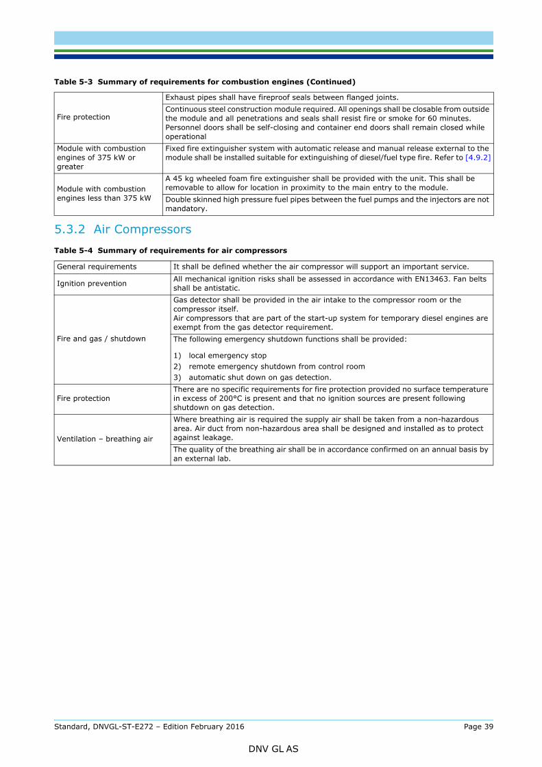
5.3.2 Air Compressors
Fire protection
Exhaust pipes shall have fireproof seals between flanged joints. Continuous steel construction module required. All openings shall be closable from outside the module and all penetrations and seals shall resist fire or smoke for 60 minutes. Personnel doors shall be self-closing and container end doors shall remain closed while operational
Module with combustion engines of 375 kW or greater
Fixed fire extinguisher system with automatic release and manual release external to the module shall be installed suitable for extinguishing of diesel/fuel type fire. Refer to [4.9.2]
Module with combustion engines less than 375 kW
A 45 kg wheeled foam fire extinguisher shall be provided with the unit. This shall be removable to allow for location in proximity to the main entry to the module. Double skinned high pressure fuel pipes between the fuel pumps and the injectors are not mandatory.
Table 5-4 Summary of requirements for air compressors
General requirements It shall be defined whether the air compressor will support an important service.
Ignition prevention All mechanical ignition risks shall be assessed in accordance with EN13463. Fan belts shall be antistatic.
Fire and gas / shutdown
Gas detector shall be provided in the air intake to the compressor room or the compressor itself. Air compressors that are part of the start-up system for temporary diesel engines are exempt from the gas detector requirement.The following emergency shutdown functions shall be provided:
1) local emergency stop2) remote emergency shutdown from control room3) automatic shut down on gas detection.
Fire protectionThere are no specific requirements for fire protection provided no surface temperature in excess of 200°C is present and that no ignition sources are present following shutdown on gas detection.
Ventilation – breathing air
Where breathing air is required the supply air shall be taken from a non-hazardous area. Air duct from non-hazardous area shall be designed and installed as to protect against leakage. The quality of the breathing air shall be in accordance confirmed on an annual basis by an external lab.
Table 5-3 Summary of requirements for combustion engines (Continued)
Standard, DNVGL-ST-E272 – Edition February 2016 Page 39
DNV GL AS
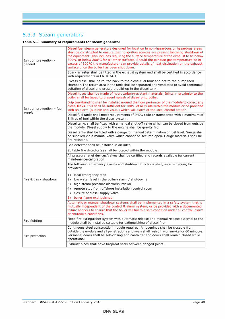
Table 5-5 Summary of requirements for steam generator
Ignition prevention - general
Diesel fuel steam generators designed for location in non-hazardous or hazardous areas shall be constructed to ensure that no ignition sources are present following shutdown of the equipment. This includes requiring the surface temperature of the exhaust to be below 300°C or below 200°C for all other surfaces. Should the exhaust gas temperature be in excess of 300°C the manufacturer can provide details of heat dissipation on the exhaust surface once the boiler has been shut down.Spark arrester shall be fitted in the exhaust system and shall be certified in accordance with requirements in EN 1834-1.
Ignition prevention – fuel supply
Excess diesel shall be routed back to the diesel fuel tank and not to the pump feed chamber. The return area in the tank shall be separated and ventilated to avoid continuous agitation of diesel and pressure build-up in the diesel tank.Diesel hoses shall be made of hydrocarbon-resistant materials. Joints in proximity to the boiler shall be taped to prevent splash of diesel onto boiler. Drip tray/bunding shall be installed around the floor perimeter of the module to collect any diesel leaks. This shall be sufficient for 100% of all fluids within the module or be provided with an alarm (audible and visual) which will alarm at the local control station.Diesel fuel tanks shall meet requirements of IMDG code or transported with a maximum of 5 litres of fuel within the diesel system.Diesel tanks shall be fitted with a manual shut-off valve which can be closed from outside the module. Diesel supply to the engine shall be gravity fed.Diesel tanks shall be fitted with a gauge for manual determination of fuel level. Gauge shall be supplied via a manual valve which cannot be secured open. Gauge materials shall be fire resistant.
Fire & gas / shutdown
Gas detector shall be installed in air inlet.
Suitable fire detector(s) shall be located within the module.
All pressure relief devices/valves shall be certified and records available for current maintenance/calibrationThe following emergency alarms and shutdown functions shall, as a minimum, be provided:
1) local emergency stop2) low water level in the boiler (alarm / shutdown)3) high steam pressure alarm/shutdown4) remote stop from offshore installation control room 5) closure of diesel supply valve 6) boiler flame extinguished.Automatic or manual shutdown systems shall be implemented in a safety system that is mutually independent of the control & alarm system, or be provided with a documented failure analysis to ensure that the boiler will fail to a safe condition under all control, alarm or shutdown conditions.
Fire fighting Fixed fire extinguisher system with automatic release and manual release external to the module shall be installed suitable for extinguishing of diesel fire.
Fire protection
Continuous steel construction module required. All openings shall be closable from outside the module and all penetrations and seals shall resist fire or smoke for 60 minutes. Personnel doors shall be self-closing and container end doors shall remain closed while operational
Exhaust pipes shall have fireproof seals between flanged joints.
Standard, DNVGL-ST-E272 – Edition February 2016 Page 40
DNV GL AS
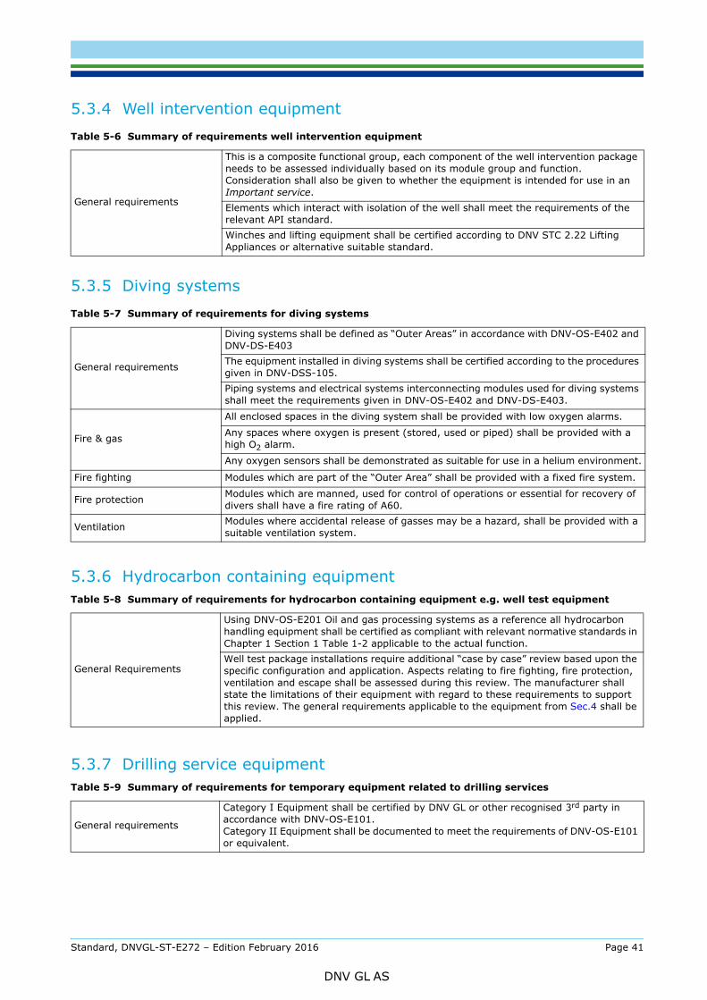
5.3.5 Diving systems
5.3.6 Hydrocarbon containing equipment
5.3.7 Drilling service equipment
Table 5-6 Summary of requirements well intervention equipment
General requirements
This is a composite functional group, each component of the well intervention package needs to be assessed individually based on its module group and function. Consideration shall also be given to whether the equipment is intended for use in an Important service.Elements which interact with isolation of the well shall meet the requirements of the relevant API standard.Winches and lifting equipment shall be certified according to DNV STC 2.22 Lifting Appliances or alternative suitable standard.
Table 5-7 Summary of requirements for diving systems
General requirements
Diving systems shall be defined as “Outer Areas” in accordance with DNV-OS-E402 and DNV-DS-E403The equipment installed in diving systems shall be certified according to the procedures given in DNV-DSS-105.Piping systems and electrical systems interconnecting modules used for diving systems shall meet the requirements given in DNV-OS-E402 and DNV-DS-E403.
Fire & gas
All enclosed spaces in the diving system shall be provided with low oxygen alarms.
Any spaces where oxygen is present (stored, used or piped) shall be provided with a high O2 alarm.
Any oxygen sensors shall be demonstrated as suitable for use in a helium environment.
Fire fighting Modules which are part of the “Outer Area” shall be provided with a fixed fire system.
Fire protection Modules which are manned, used for control of operations or essential for recovery of divers shall have a fire rating of A60.
Ventilation Modules where accidental release of gasses may be a hazard, shall be provided with a suitable ventilation system.
Table 5-8 Summary of requirements for hydrocarbon containing equipment e.g. well test equipment
General Requirements
Using DNV-OS-E201 Oil and gas processing systems as a reference all hydrocarbon handling equipment shall be certified as compliant with relevant normative standards in Chapter 1 Section 1 Table 1-2 applicable to the actual function.Well test package installations require additional “case by case” review based upon the specific configuration and application. Aspects relating to fire fighting, fire protection, ventilation and escape shall be assessed during this review. The manufacturer shall state the limitations of their equipment with regard to these requirements to support this review. The general requirements applicable to the equipment from Sec.4 shall be applied.
Table 5-9 Summary of requirements for temporary equipment related to drilling services
General requirements
Category I Equipment shall be certified by DNV GL or other recognised 3rd party in accordance with DNV-OS-E101. Category II Equipment shall be documented to meet the requirements of DNV-OS-E101 or equivalent.
Standard, DNVGL-ST-E272 – Edition February 2016 Page 41
DNV GL AS
activitiesEquipment intended for use on an offshore installation where hydrocarbon liquids or gasses will never be present are permitted to replace certain requirements in this standard with the alternatives listed in [5.4.1] to [5.4.4].
Where alternatives are applied according to this clause, such limitations shall be noted on the DNV GL product certificate.
Guidance note:Proximity to hydrocarbons where accidental release may reach the offshore installation (i.e. work relating to subsea wells or platform support vessels) shall be considered as areas where hydrocarbons can occur.
---e-n-d---of---g-u-i-d-a-n-c-e---n-o-t-e---
5.4.1 Inclination on non-important service equipmentInclination angles do not impact the safe operation of the equipment under the following conditions:
— equipment is not used for an important service and
— hydrocarbon gasses or liquids are not present.
Under these conditions the requirements for Inclination in Table 4-1 are not applicable.
5.4.2 BatteriesBatteries are not required to be in zone 2 certified safe equipment enclosures when hydrocarbons do not occur. Batteries shall be located in a battery box or locker.
5.4.3 Gas detectionGas detection on the equipment or at air intakes is not required where hydrocarbon gasses do not occur.
5.4.4 Combustion engines and steam generatorsWhen hydrocarbon gasses or liquids do not occur the maximum surface temperature of a combustion engine or steam generator shall be 220°C and spark arrestors are not required.
Standard, DNVGL-ST-E272 – Edition February 2016 Page 42
DNV GL AS
6.1 GeneralBefore the module is taken into service, it shall be safely secured to the deck or supporting structure (See Sec.3).
Cables for power supply and other hook-ups are excluded from certification to this standard however should be suitably protected, mechanically and electrically, when installed on site. Cabling shall be adequately secured to prevent mechanical damage or short circuit and shall not cause a hazard to the offshore installation.
6.2 Interfaces between module and offshore installationTo ensure correct and suitable connections to the module, the certification shall specify all relevant interfaces between the module and the offshore installation. These interfaces may include hook up of:
— electric power supplies— telephones and PA/GA systems— signals to and from the control room — utility systems, e.g., air, nitrogen, steam, hydraulics, water, drains, diesel.
The specification of interfaces shall be sufficiently detailed and unambiguous that the equipment can be safely and correctly hooked up to the permanent utilities on the offshore installation.
6.2.1 Signal from module or equipment to CCRDepending on the configuration of the module, the following signals shall be transmittable:
— Gas detection.— Fire detection / fire alarm push button.— Fire extinguishing medium released.— Loss of pressurisation.— Fire damper position indication (if fire damper used)— Status of monitoring /control systems on the module. These may be connected to a common alarm
signal. — Condition monitoring alarms.
Guidance note:This includes alarms from monitoring systems for machinery, processes and similar alarms. Equipment, which has this local monitoring system, may have a condition monitoring signal output to the control room if the equipment can be operated unmanned.
---e-n-d---of---g-u-i-d-a-n-c-e---n-o-t-e---
Suitably certified termination facilities should be provided at a convenient location to allow hook-up to the offshore installation cables. Signals from modules to the CCR shall be voltage-free contacts. Regardless of location, such termination facilities should be suitably certified safe equipment rated for the area in which it is located but minimum of zone 2.
Where voltages remain on internal components following shutdown, such equipment is to be marked:
“WARNING, INTERNAL VOLTAGES MAY REMAIN AFTER MODULE SHUTDOWN:ENSURE THAT ATMOSPHERE IS NON-HAZARDOUS BEFORE OPENING.”
6.2.2 Signals from CCR to module or equipmentDepending on the configuration of the module or equipment, the following signals shall be transmittable:
— Emergency stop (e.g., rotating/moving machinery).— Emergency Shutdown, e.g., non-certified equipment and/or safety/battery systems.— Information via the offshore installations alarm system (PA/GA system/Telephone).
Standard, DNVGL-ST-E272 – Edition February 2016 Page 43
DNV GL AS
Instructions for hook-up/installation of the module shall always accompany the module detailing, at a minimum, the following:
— Instructions on hook-up of equipment incorporating input voltages and required protection settings from the offshore installation.
— Description of the conditions/functions the module shall perform and any safety precautions required to operate within prescribed condition.
— Maintenance requirements and periodic checks.— Valid certificate of lifting equipment.
Instruction for hook-up/installation shall be provided for approval as part of the design assessment.
Copy of the design assessment documentation and referenced drawings shall be available for each module to allow confirmation of “as built” condition at time of certification.
Standard, DNVGL-ST-E272 – Edition February 2016 Page 44
DNV GL AS
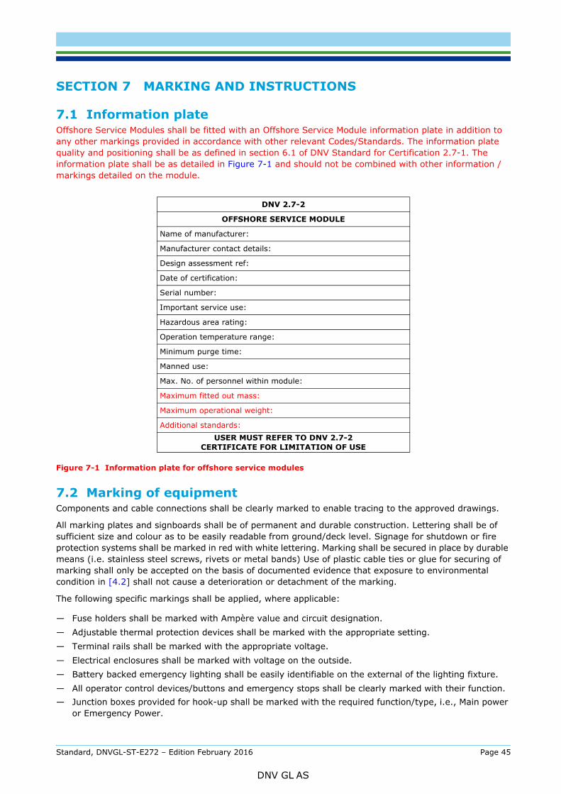
7.1 Information plateOffshore Service Modules shall be fitted with an Offshore Service Module information plate in addition to any other markings provided in accordance with other relevant Codes/Standards. The information plate quality and positioning shall be as defined in section 6.1 of DNV Standard for Certification 2.7-1. The information plate shall be as detailed in Figure 7-1 and should not be combined with other information /markings detailed on the module.
Figure 7-1 Information plate for offshore service modules
7.2 Marking of equipmentComponents and cable connections shall be clearly marked to enable tracing to the approved drawings.
All marking plates and signboards shall be of permanent and durable construction. Lettering shall be of sufficient size and colour as to be easily readable from ground/deck level. Signage for shutdown or fire protection systems shall be marked in red with white lettering. Marking shall be secured in place by durable means (i.e. stainless steel screws, rivets or metal bands) Use of plastic cable ties or glue for securing of marking shall only be accepted on the basis of documented evidence that exposure to environmental condition in [4.2] shall not cause a deterioration or detachment of the marking.
The following specific markings shall be applied, where applicable:
— Fuse holders shall be marked with Ampère value and circuit designation.— Adjustable thermal protection devices shall be marked with the appropriate setting.— Terminal rails shall be marked with the appropriate voltage.— Electrical enclosures shall be marked with voltage on the outside.— Battery backed emergency lighting shall be easily identifiable on the external of the lighting fixture.— All operator control devices/buttons and emergency stops shall be clearly marked with their function.— Junction boxes provided for hook-up shall be marked with the required function/type, i.e., Main power
or Emergency Power.
DNV 2.7-2
OFFSHORE SERVICE MODULE
Name of manufacturer:
Manufacturer contact details:
Design assessment ref:
Date of certification:
Serial number:
Important service use:
Hazardous area rating:
Operation temperature range:
Minimum purge time:
Manned use:
Max. No. of personnel within module:
Maximum fitted out mass:
Maximum operational weight:
Additional standards:USER MUST REFER TO DNV 2.7-2
CERTIFICATE FOR LIMITATION OF USE
Standard, DNVGL-ST-E272 – Edition February 2016 Page 45
DNV GL AS
power isolator.— Enclosures containing intrinsically safe circuits shall be marked.— Warning for internal voltages shall be marked. — Portable fire extinguisher holder shall be marked with the extinguisher type and size.
Modules intended for connection to platform power supply systems shall have the following data clearly marked at the connection point:
— system voltage(s)— maximum supply protection value— frequency— short circuit current— rated short circuit breaking capacity— type of distribution system, e.g. IT, TN, etc.
Standard, DNVGL-ST-E272 – Edition February 2016 Page 46
DNV GL AS
8.1 GeneralCertification consists of the following steps as applicable:
— design assessment
— production inspection & testing
— inspection of the completed installation
— functional testing (if applicable)
— plating and marking
— issuance of certificates.
DNV GL may issue a DNV GL product certificate for modules which are designed, manufactured and tested according to the requirements of this standard.
The DNV GL product certificate shall state the scope of DNV GL’s involvement and any requirements or limitations for the use of the offshore service module. The DNV GL product certificate will include reference to the applicable certification for the lifting structure.
To ensure consistent application of this standard and for the quality and safety of the products Certified to it, no company other than DNV GL shall provide any formal interpretations relating to its, or the requirements described in the standard. Approval engineers and/or surveyors undertaking certification or Surveillance activities in accordance with this standard (either in whole or part) shall be confirmed competent to do so via a documented training and competence scheme considered acceptable and equivalent to that used by DNV GL.
8.2 Application for certificationAn application for approval and certification should be sent to the local DNV GL office. The following information shall be included:
— A description of the type of module (See Sec.5).
— Whether the module is for important service as defined in Section [5.1].
— Whether the container structure is already approved and which standard has been used.
— The hazardous area in which the container may be located.
— Whether the module is going to be manned or unmanned.
— The place of manufacture.
— Details of other standards and regulations to be covered.
8.3 Approval schemesDNV GL can provide an individual (case) approval if the manufacturer intends to build one unit or a limited batch of modules. The manufacturer shall specify the number of modules to be covered by the approval. The maximum number of modules to be covered under one case approval shall normally be limited to 20.
If series production is intended, or if further orders for the same module design are expected in the future, type approval will normally be given. Type Approval Certificates are normally issued to the manufacturer of the module. If modules are made by a manufacturer on behalf of the owner of a design type, both the owner of the design type and the manufacturer will be listed in the Type Approval Certificate.
For further details on type approval process please refer to DNV Standard for Certification 1.2 Type Approval
Modules types satisfying the requirements of DNV GL type approvals are listed on the DNV GL website, www.dnvgl.com for external viewing.
Standard, DNVGL-ST-E272 – Edition February 2016 Page 47
DNV GL AS
Documentation for design assessment shall be submitted electronically (in a PDF format) to the local DNV GL station prior to manufacturing. Documentation required for review shall be clarified based on the module design/functions following contact with DNV GL.
In cases where experience and/or other findings show that safety hazards may arise in connection with items not covered directly by the existing requirements, DNV GL may determine and advise supplementary requirements which shall be met in order to reach and maintain the overall safety standard.
8.5 Survey and testing Surveys are undertaken to confirm assembly and functionality of the module in accordance with the approved drawings. Surveys may be delayed should design documentation not be submitted in sufficient time to allow the assessment to be concluded.
Depending upon the assembly or functions within the module (e.g. passive fire protection) interim surveys may be required to confirm assembly to the approved design.
Table 8-1 details typical survey, functional test and documentation review requirements. Additional requirements may apply depending upon the function of the module.
8.6 Certification of existing containersExisting modules which have previously been certified by DNV GL may be re-certified after modification or upgrading. Such re-certification will be based on already existing certificates as far as applicable, in addition to approval and inspection of new installations.
Existing modules that have not previously been certified by DNV GL may in certain cases be considered for certification. All relevant documentation shall be submitted for verification including design assessment and associated technical documentation. If the documentation is incomplete, additional requirements may be specified by DNV GL. Each module is to be thoroughly inspected and tested as appropriate.
8.7 Retention of certificates
8.7.1 Maintenance of certificates /periodic inspectionsOffshore service modules which are installed or intended for installation on a DNV GL classed offshore Installation are considered part of the class scope and shall be inspected by a DNV GL surveyor at the inspection intervals applicable to the offshore installation.
Modules which are also certified to DNV 2.7-1 or 2.7-3 require annual inspection according to these standards. Modules which are based on a ship service container must be subject to structural inspections at the same intervals as hull structures.
Guidance note:Shelf state legislation or client specific requirements may require periodic inspection of the Offshore Service Module.
---e-n-d---of---g-u-i-d-a-n-c-e---n-o-t-e---
Table 8-1 Typical production survey and testing requirements
Survey
Confirm assembly of the unit in accordance with approved drawings and accordance with requirements in this standard.Confirm certified safe equipment is installed as per certificate and accurate to hazardous area schedule.Review manufacturing records to determine suitable insulation and testing of electrical equipment. Records of competency for installation/inspection personnel to nationally recognised procedures may be requested.Operating instructions where relevant for safe operation of the module. Ensure any special precautions for use and limitations are clearly identified.
Functional testingFunction tests of essential-/safety systems including, e.g., electrical, alarm and HVAC systems.
Function tests of shut-down actions as per approved shutdown arrangement.
Standard, DNVGL-ST-E272 – Edition February 2016 Page 48
DNV GL AS
A module is considered as having been modified when;
— Components not on approved design are used.— Modification of equipment from the approved design.— Function or performance is changed.
In such cases re-certification shall be undertaken to ensure continued validity of the certificate, the scope of which shall be agreed on a case by case basis.
Repair or modification of structural aspects shall be surveyed according to the requirements of the original structural standard. Note any hot work to the primary structure shall be especially considered.
Guidance note:Replacement of components or minor repairs to original approved condition - DNV GL involvement is not necessary.
---e-n-d---of---g-u-i-d-a-n-c-e---n-o-t-e---
8.7.3 Withdrawal of certificationShould a module issued with a DNV GL product certificate be subsequently found not to comply with the requirements of this standard, DNV GL may withdraw the certificate for that module.
Detailed justification shall be provided to the manufacturer or owner of the module describing the reasons for withdrawal of certification. Following rectification of any nonconformity, the DNV GL product certificate may be re-instated.
Standard, DNVGL-ST-E272 – Edition February 2016 Page 49
DNV GL AS

SAF
DNV GLDriven by our purpose of safeguarding life, property and the environment, DNV GL enables organizations to advance the safety and sustainability of their business. We provide classification and technical assurance along with software and independent expert advisory services to the maritime, oil and gas, and energy industries. We also provide certification services to customers across a wide range of industries. Operating in more than 100 countries, our 16 000 professionals are dedicated to helping our customers make the world safer, smarter and greener.
ER, SMARTER, GREENER


![AUT QUALIFICATION OF APPLUS+ RTD IWEX SYSTEM ...1a1b8052-a937-4261-9a38...DNV GL AS, and follows the requirements of DNVGL-ST-F101 [1] and DNVGL-RP-F118 [2]. DNV GL has witnessed all](https://static.fdocuments.in/doc/165x107/6102fcc2f64e88228972191f/aut-qualification-of-applus-rtd-iwex-system-1a1b8052-a937-4261-9a38-dnv.jpg)