Performance Evaluation of Mutual Funds in India-Jaiprakash-0478
The electronic pdf version of this document, available free of chargefrom http://www.dnvgl.com, is the officially binding version.
DNV GL AS
SERVICE SPECIFICATION
DNVGL-SE-0478 Edition July 2017
Verification of subsea facilities
FOREWORD
DNV GL service specifications contain procedural requirements for obtaining and retainingcertificates and other conformity statements to the objects, personnel, organisations and/oroperations in question.
© DNV GL AS July 2017
Any comments may be sent by e-mail to [email protected]
This service document has been prepared based on available knowledge, technology and/or information at the time of issuance of thisdocument. The use of this document by others than DNV GL is at the user's sole risk. DNV GL does not accept any liability or responsibilityfor loss or damages resulting from any use of this document.
Cha
nges
- c
urre
nt
Service specification — DNVGL-SE-0478. Edition July 2017 Page 3Verification of subsea facilities
DNV GL AS
CHANGES – CURRENT
GeneralThis document supersedes the June 2004 edition of DNV-OSS-306.The purpose of the revision of this service document is to comply with the new DNV GL document reference code system and profile requirements following the merger between DNV and GL in 2013. Changes mainly consist of updated company name and references to other documents within the DNV GL portfolio.
Some references in this service document may refer to documents in the DNV GL portfolio not yet published (planned published within 2017). In such cases please see the relevant legacy DNV or GL document. References to external documents (non-DNV GL) have not been updated.
Editorial correctionsIn addition to the above stated changes, editorial corrections may have been made.
Con
tent
s
Service specification — DNVGL-SE-0478. Edition July 2017 Page 4Verification of subsea facilities
DNV GL AS
CONTENTS
Changes – current.................................................................................................. 3
Section 1 General....................................................................................................51.1 General............................................................................................. 51.2 Risk based verification..................................................................... 71.3 Defining a verification plan...............................................................81.4 DNV GL subsea facility statements of compliance.............................81.5 Definitions/abbreviations................................................................. 81.6 References...................................................................................... 11
Section 2 Service overview................................................................................... 122.1 General........................................................................................... 122.2 Service process...............................................................................122.3 Project initiation............................................................................. 142.4 Project realization.......................................................................... 142.5 Project operation............................................................................ 202.6 Verification documents................................................................... 21
Appendix A Selection of verification level.............................................................22A.1 General........................................................................................... 22A.2 Trigger questions............................................................................22
Appendix B Detailed example scope of work tables for verification...................... 25B.1 General........................................................................................... 25B.2 Description of terms used in the verification lists...........................25B.3 Overall project management.......................................................... 27B.4 Design.............................................................................................27B.5 Construction................................................................................... 47
Appendix C Examples of verification documents...................................................67C.1 Verification documents................................................................... 67C.2 Use of quality management systems.............................................. 69C.3 Document forms............................................................................. 71
Changes – historic................................................................................................77

Service specification — DNVGL-SE-0478. Edition July 2017 Page 5Verification of subsea facilities
DNV GL AS
SECTION 1 GENERAL
1.1 General
1.1.1 Introduction
1.1.1.1 This DNV GL service specification gives criteria for and guidance on verification of the integrity andfunction of parts or phases of subsea facilities. The suite of inter-related DNVGL-SE documents consist of ageneral description of the verification systematics (DNVGL-SE-0474) and object specific documents - thisdocument (DNVGL-SE-0478) offers the reader the application of the common framework and overview ofprocesses in risk verification, to subsea facilities.
— It introduces a levelled description of verification involvement during all phases of an asset's life.— The document facilitates a categorisation into risk levels high, medium and low, assisting in an evaluation
of the risk level.— The document assists in planning the verification through the making of a verification plan, and describes
the DNV GL documentation of the process throughout.
The document provides an international standard allowing transparent and predictable verification scope, aswell as defining terminology for verification involvement.
1.1.1.2 This specification falls under the top level document DNVGL-SE-0474 Risk based verification.
1.1.1.3 The descriptions in this specification directly support a simplified verification planning as describedin DNVGL-SE-0474 Sec.2. When using the advanced or combined planning, the descriptions will give goodreferences and starting points.
Guidance note:The latest revision of all DNV GL documents may be found in the publications list in the DNV GL web site www.dnvgl.com.
---e-n-d---o-f---g-u-i-d-a-n-c-e---n-o-t-e---
1.1.2 Objectives
1.1.2.1 The objectives of this specification are to describe the following for a subsea facility:
— preparation of a verification plan using DNV GL’s risk differentiated levels of verification activities anddetailed example scope of work tables
— DNV GL’s implementation and reporting of the verification plan.
1.1.3 Scope of application for verification
1.1.3.1 This specification may be adopted for the verification of parts of subsea facilities or selected projectphases.
1.1.3.2 Subsea facilities typically comprise the following systems:
— downhole system— subsea wellhead and tree system (including: choke, tubing hanger and connection systems)— manifold, foundations and template— flowlines and risers (including dynamic umbilical risers)— subsea control umbilicals— subsea production control system— subsea processing system
Service specification — DNVGL-SE-0478. Edition July 2017 Page 6Verification of subsea facilities
DNV GL AS
— well intervention/completion/workover system— ROT intervention system.
which are applied in various configurations and tailored to each particular project’s specific requirements.
1.1.3.3 This specification describes the principles of a levelled verification involvement. These principles maybe applied both for planning of any need or obligations for independent external verification (third party) aswell as internal company verification (second party).
1.1.4 Structure of this document— This section explains the relationship between this document and DNV GL’s overall risk based verification
systematics.— Sec.2 describes the activities for each project and the project phases for a subsea system.— App.A poses trigger questions to assist in the selection of verification level example.— App.B gives detailed scope of work tables for the different phases and levels of involvement. These tables
are the basis for the development of project specific scope of work tables.— App.C gives example verification documents and describes the documents issued during and as a result of
the verification process. The use of quality management systems is addressed here also.
Service specification — DNVGL-SE-0478. Edition July 2017 Page 7Verification of subsea facilities
DNV GL AS
1.2 Risk based verification
1.2.1 Elements of the service
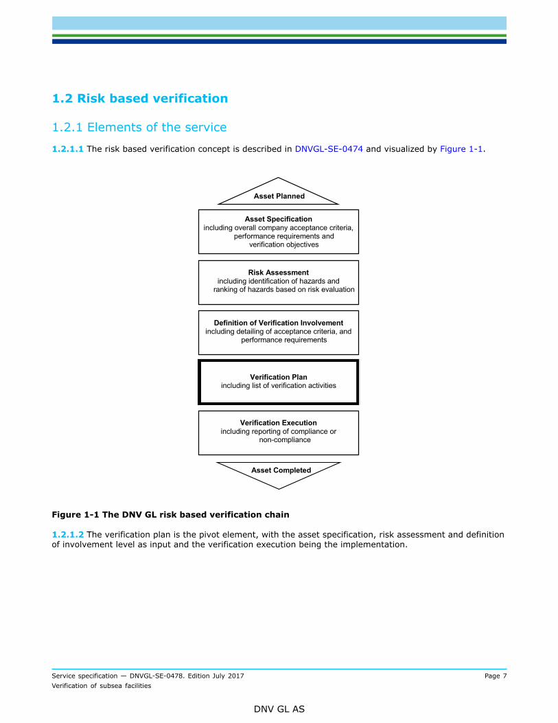
1.2.1.1 The risk based verification concept is described in DNVGL-SE-0474 and visualized by Figure 1-1.
Figure 1-1 The DNV GL risk based verification chain
1.2.1.2 The verification plan is the pivot element, with the asset specification, risk assessment and definitionof involvement level as input and the verification execution being the implementation.

Service specification — DNVGL-SE-0478. Edition July 2017 Page 8Verification of subsea facilities
DNV GL AS
1.3 Defining a verification plan
1.3.1 Risk based verification planning
1.3.1.1 The selection of the level of verification shall depend on the risk level of each element having animpact on the management of hazards and associated risk levels of the asset. The planning can be simplifiedor detailed. This is further described in DNVGL-SE-0474.
1.3.1.2 This specification mainly aids in a simplified preparation of the verification plan.Guidance note:Risk can be evaluated based on safety, environmental impact, economics, schedule, public relations, reputation or other criteriaset by the owner. The example tables are mainly generated on the basis of safety and integrity risks. With business risk being thedriver for verification involvement this will normally warrant a need to use the analytical approach and no the simplified one.
---e-n-d---o-f---g-u-i-d-a-n-c-e---n-o-t-e---
1.4 DNV GL subsea facility statements of compliance
1.4.1 General on verification
1.4.1.1 Verification describes the individual activities undertaken by DNV GL at the various stages of design,construction and operation of the subsea facility. The scope of the verification plan is ultimately determinedby the owner.
1.4.2 Statement of conformity
1.4.2.1 A statement of conformity may be issued by DNV GL to confirm compliance according to the scope ofwork.
1.4.3 General on certification
1.4.3.1 Certification describes the totality of verification activities leading up to the issue of a certification ofconformity. The scope of work and verification plan, called a certification plan, is set by DNV GL. All designand construction aspects, related to subsea facility safety and integrity, must be covered by the certificationplan.
1.4.3.2 This service specification does not define the scope of work necessary to achieve a DNV GLcertificate of conformity.
1.5 Definitions/abbreviations
1.5.1 General
1.5.1.1 Relevant definitions in ISO 13620-8 also apply to this document.

Service specification — DNVGL-SE-0478. Edition July 2017 Page 9Verification of subsea facilities
DNV GL AS
1.5.2 AbbreviationsTable 1-1 Abbreviations
Abbreviation Description
DCS distributed control system
EDU electrical distribution unit
EPU electrical power unit
ETU electronic test unit
HPU hydraulic power unit
HTP hydraulic test panel
MCC motor control centre
MCS master control station
MQC multi quick connector
PT pressure transmitter
SCM subsea control module
SCMMB SCM mounting base
SCR subsea control room
SCU subsea control unit
SDU subsea distribution unit
SEM subsea electronic module
SPCU subsea power and communication unit
TT temperature transmitter
TUTU topside umbilical termination unit
UPS uninterrupted power supply
1.5.3 Verbal formsTable 1-2 Definitions of verbal forms
Term Definition
shall indicates requirements strictly to be followed in order to conform to this document and fromwhich no deviation is permitted
should indicates that among several possibilities, one is recommended as particularly suitable,without mentioning or excluding others, or that a certain course of action is preferred but notnecessarily required, other possibilities may be applied subject to agreement
may verbal form used to indicate a course of action permissible within the limits of the document
Service specification — DNVGL-SE-0478. Edition July 2017 Page 10Verification of subsea facilities
DNV GL AS
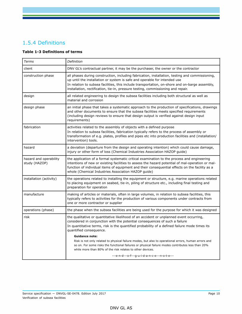
1.5.4 DefinitionsTable 1-3 Definitions of terms
Terms Definition
client DNV GL’s contractual partner, it may be the purchaser, the owner or the contractor
construction phase all phases during construction, including fabrication, installation, testing and commissioning,up until the installation or system is safe and operable for intended useIn relation to subsea facilities, this include transportation, on-shore and on-barge assembly,installation, rectification, tie-in, pressure testing, commissioning and repair.
design all related engineering to design the subsea facilities including both structural as well asmaterial and corrosion
design phase an initial phase that takes a systematic approach to the production of specifications, drawingsand other documents to ensure that the subsea facilities meets specified requirements(including design reviews to ensure that design output is verified against design inputrequirements)
fabrication activities related to the assembly of objects with a defined purposeIn relation to subsea facilities, fabrication typically refers to the process of assembly ortransformation of e.g. plates, profiles and pipes etc into production facilities and (installation/intervention) tools.
hazard a deviation (departure from the design and operating intention) which could cause damage,injury or other form of loss (Chemical Industries Association HAZOP guide)
hazard and operabilitystudy (HAZOP)
the application of a formal systematic critical examination to the process and engineeringintentions of new or existing facilities to assess the hazard potential of mal-operation or mal-function of individual items of equipment and their consequential effects on the facility as awhole (Chemical Industries Association HAZOP guide)
installation (activity) the operations related to installing the equipment or structure, e.g. marine operations relatedto placing equipment on seabed, tie-in, piling of structure etc., including final testing andpreparation for operation
manufacture making of articles or materials, often in large volumes, in relation to subsea facilities, thistypically refers to activities for the production of various components under contracts fromone or more contractor or supplier
operations (phase) the phase when the subsea facilities are being used for the purpose for which it was designed
risk the qualitative or quantitative likelihood of an accident or unplanned event occurring,considered in conjunction with the potential consequences of such a failureIn quantitative terms, risk is the quantified probability of a defined failure mode times itsquantified consequence.
Guidance note:Risk is not only related to physical failure modes, but also to operational errors, human errors andso on. For some risks the functional failures or physical failure modes contributes less than 20%while more than 80% of the risk relates to other devices.
---e-n-d---o-f---g-u-i-d-a-n-c-e---n-o-t-e---

Service specification — DNVGL-SE-0478. Edition July 2017 Page 11Verification of subsea facilities
DNV GL AS
Terms Definition
risk reduction measures those measures taken to reduce the risks to the operation of subsea facilities and to thehealth and safety of personnel associated with it or in its vicinity by:
— reduction in the probability of failure— mitigation of the consequences of failure.
Guidance note:The usual order of preference of risk reduction measures is:
a) inherent safety
b) prevention
c) detection
d) control
e) mitigation
f) emergency response.
---e-n-d---o-f---g-u-i-d-a-n-c-e---n-o-t-e---
safety objectives the safety goals for the construction, operation and decommissioning of the subsea facilitiesincluding acceptance criteria for the level of risk acceptable to the owner
statement of conformity a statement or report signed by a qualified party affirming that, at the time of assessment,the defined subsea facilities phase, or collection of activities, met the requirements stated bythe owner
verification an examination to confirm that an activity, a product or a service is in accordance withspecified requirements
Guidance note:The examination shall be based on information, which can be proved true, based on factsobtained through observation, measurement, test or other means. ISO 8402: 1994: Verification:Confirmation by examination and provision of objective evidence that specified requirements havebeen fulfilled.
---e-n-d---o-f---g-u-i-d-a-n-c-e---n-o-t-e---
1.6 ReferencesTable 1-4 References
Document code Title
A Guide to Hazard andOperability Studies
Chemical Industries Association Limited, London (1979)
ISO 8402 Quality – Vocabulary, 1994, International Organization for Standardization, Geneva
BS 4778 Quality Vocabulary, Part 2 Quality Concepts and Related Definitions, 1991, BritishStandards Institute, London
EN 45011 General Criteria for Certification Bodies Operating Product Certification, 1998, EuropeanCommittee for Standardization, Brussels
EN ISO 13628 Design and operation of subsea production systems - series
Service specification — DNVGL-SE-0478. Edition July 2017 Page 12Verification of subsea facilities
DNV GL AS
SECTION 2 SERVICE OVERVIEW
2.1 General
2.1.1 Objectives
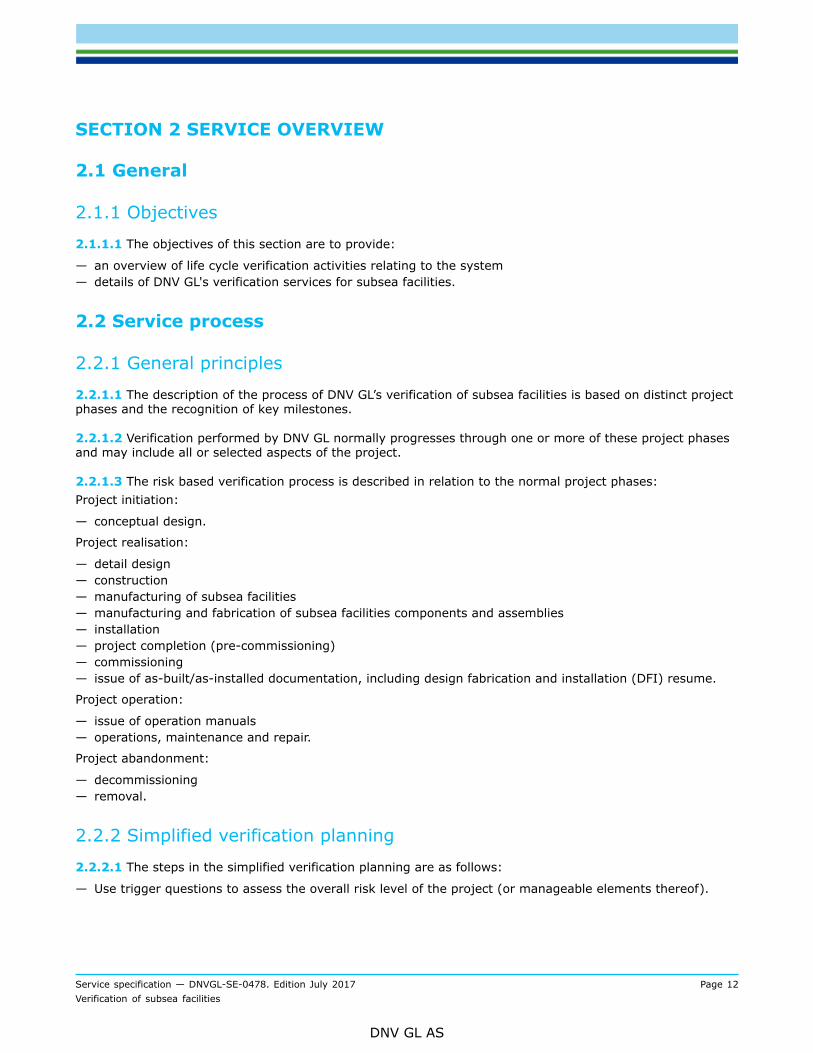
2.1.1.1 The objectives of this section are to provide:
— an overview of life cycle verification activities relating to the system— details of DNV GL's verification services for subsea facilities.
2.2 Service process
2.2.1 General principles
2.2.1.1 The description of the process of DNV GL’s verification of subsea facilities is based on distinct projectphases and the recognition of key milestones.
2.2.1.2 Verification performed by DNV GL normally progresses through one or more of these project phasesand may include all or selected aspects of the project.
2.2.1.3 The risk based verification process is described in relation to the normal project phases:Project initiation:
— conceptual design.
Project realisation:
— detail design— construction— manufacturing of subsea facilities— manufacturing and fabrication of subsea facilities components and assemblies— installation— project completion (pre-commissioning)— commissioning— issue of as-built/as-installed documentation, including design fabrication and installation (DFI) resume.
Project operation:
— issue of operation manuals— operations, maintenance and repair.
Project abandonment:
— decommissioning— removal.
2.2.2 Simplified verification planning
2.2.2.1 The steps in the simplified verification planning are as follows:
— Use trigger questions to assess the overall risk level of the project (or manageable elements thereof).

Service specification — DNVGL-SE-0478. Edition July 2017 Page 13Verification of subsea facilities
DNV GL AS
— Evaluate the risk against the relevant owner or project acceptance criteria (often this can be directly tiedto the owner core values or a sub-set of these) and decide whether the general verification involvementshall be low, medium or high.
— Use the example detailed scope of work tables in App.B to make a first draft of a verification plan— Generate the project specific verification plan by including a project specific engineering judgment or risk
analysis to adjust the table to suit the project.— Perform the verification execution according to the verification plan, making revision to the plan if and
when necessary.— Report the verification.
2.2.2.2 The trigger questions are included in App.A.
2.2.2.3 Generic scopes of work for verification at the three levels of verification, low (L), medium (M) andhigh (H), are given in the tables in this section.
2.2.2.4 Project specific detailed scope of work descriptions, based on the generic scopes of work tables andshowing all the activities to be verified, should be made. Examples of the level of detail are given in App.B.
2.2.2.5 It is the tables in this section that give the principle difference between the levels of verificationinvolvement. The detailed example tables are to be treated as examples only. They shall not be used withouta project specific confirmation of their completeness.
2.2.2.6 The project specific scope of work definition, derived from the tables in App.B (or similar), shall bepart of the final DNV GL verification report.
2.2.3 Selection of level of verification
2.2.3.1 The selection of the level of verification for the simplified verification planning is facilitated by thetrigger questions included in App.A.
2.2.4 Codes, standards and reference documents
2.2.4.1 The verification process described in this document is not tailored to a specific technical standard,code or reference document.
2.2.4.2 It is recommended to use internationally recognised codes or standards. Where combinations ofstandards and external criteria are used the exact terms of reference and documents to be issued shall beagreed at the beginning of the project and formally defined in the contract.
2.2.4.3 It is recommended strongly not to mix standards due to the possible differences in safetyphilosophies.
Guidance note:Most standards are a coherent collection of requirements for all the relevant aspects of a pipeline system. These aspects, e.g. loadand resistance, are normally among themselves adjusted to give an overall acceptable safety level. To pick requirements fromdifferent standards can then easily result in unpredictable (low) levels of safety, and non-uniform level of safety.
---e-n-d---o-f---g-u-i-d-a-n-c-e---n-o-t-e---

Service specification — DNVGL-SE-0478. Edition July 2017 Page 14Verification of subsea facilities
DNV GL AS
2.3 Project initiation
2.3.1 Verification during conceptual design
2.3.1.1 Verification during the conceptual and/or feasibility studies of a project and in the early stages of aproject can reduce the need for verification during the design and construction phases, and can reduce costsduring the long term operation, inspection and maintenance phases.
2.3.1.2 It is recommended to combine the mechanical design verification during project initiation phase withadditional review of:
— environmental aspects— project schedule— cost.
2.3.1.3 During this phase it can be beneficial to make an initial verification plan. Risk evaluations are carriedout during this phase and should be used to get an indication of the general verification level: low, mediumor high.
2.4 Project realization
2.4.1 General
2.4.1.1 All design and construction aspects, relevant to subsea facility, may be covered by the life cycleverification.
2.4.1.2 In this specification the split in the scope of work between design and construction is made betweensets of requirements (specifications) developed during design and description of the steps necessary tosatisfy the specification (procedures) showing how construction will be implemented.
Guidance note:The split between design and construction may vary, but it is useful spend some time on the definition to reduce interfaceproblems later.
---e-n-d---o-f---g-u-i-d-a-n-c-e---n-o-t-e---
2.4.2 Verification of overall project management
2.4.2.1 Verification of the overall project management is the examination of the means of controlling theentire subsea development project, or the phase for which verification is undertaken.
2.4.2.2 This verification should confirm that the necessary controls are in place to ensure information flowacross the various interfaces. It is especially important where separate contractors have been employed fordifferent phases of the project such as design and installation.
2.4.2.3 Typically the documentation is expected to be in line with ISO 9000 requirements.
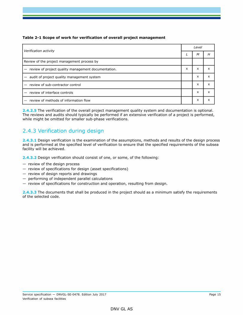
2.4.2.4 Definition of scope of work for verification of overall project management should follow Table 2-1.
Service specification — DNVGL-SE-0478. Edition July 2017 Page 15Verification of subsea facilities
DNV GL AS
Table 2-1 Scope of work for verification of overall project management
LevelVerification activity
L M H
Review of the project management process by
— review of project quality management documentation. x x x
— audit of project quality management system x x
— review of sub-contractor control x x
— review of interface controls x x
— review of methods of information flow x x
2.4.2.5 The verification of the overall project management quality system and documentation is optional.The reviews and audits should typically be performed if an extensive verification of a project is performed,while might be omitted for smaller sub-phase verifications.
2.4.3 Verification during design
2.4.3.1 Design verification is the examination of the assumptions, methods and results of the design processand is performed at the specified level of verification to ensure that the specified requirements of the subseafacility will be achieved.
2.4.3.2 Design verification should consist of one, or some, of the following:
— review of the design process— review of specifications for design (asset specifications)— review of design reports and drawings— performing of independent parallel calculations— review of specifications for construction and operation, resulting from design.
2.4.3.3 The documents that shall be produced in the project should as a minimum satisfy the requirementsof the selected code.
Service specification — DNVGL-SE-0478. Edition July 2017 Page 16Verification of subsea facilities
DNV GL AS
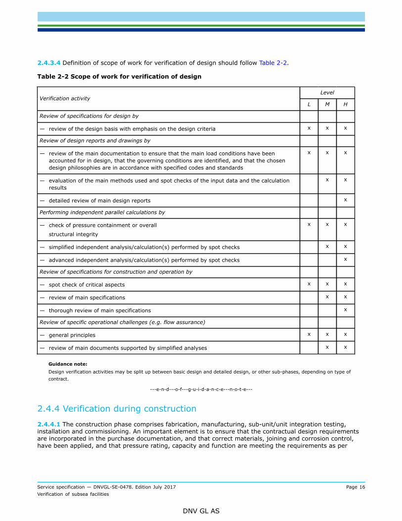
2.4.3.4 Definition of scope of work for verification of design should follow Table 2-2.
Table 2-2 Scope of work for verification of design
LevelVerification activity
L M H
Review of specifications for design by
— review of the design basis with emphasis on the design criteria x x x
Review of design reports and drawings by
— review of the main documentation to ensure that the main load conditions have beenaccounted for in design, that the governing conditions are identified, and that the chosendesign philosophies are in accordance with specified codes and standards
x x x
— evaluation of the main methods used and spot checks of the input data and the calculationresults
x x
— detailed review of main design reports x
Performing independent parallel calculations by
— check of pressure containment or overall
structural integrity
x x x
— simplified independent analysis/calculation(s) performed by spot checks x x
— advanced independent analysis/calculation(s) performed by spot checks x
Review of specifications for construction and operation by
— spot check of critical aspects x x x
— review of main specifications x x
— thorough review of main specifications x
Review of specific operational challenges (e.g. flow assurance)
— general principles x x x
— review of main documents supported by simplified analyses x x
Guidance note:Design verification activities may be split up between basic design and detailed design, or other sub-phases, depending on type ofcontract.
---e-n-d---o-f---g-u-i-d-a-n-c-e---n-o-t-e---
2.4.4 Verification during construction
2.4.4.1 The construction phase comprises fabrication, manufacturing, sub-unit/unit integration testing,installation and commissioning. An important element is to ensure that the contractual design requirementsare incorporated in the purchase documentation, and that correct materials, joining and corrosion control,have been applied, and that pressure rating, capacity and function are meeting the requirements as per
Service specification — DNVGL-SE-0478. Edition July 2017 Page 17Verification of subsea facilities
DNV GL AS
approved specifications and procedures. It is imperative that relevant preparations for this is started as earlyas possible, e.g. by the appointment of a vendor supply verification co-ordinator.
2.4.4.2 Verification during construction is carried out by means of full time attendance, audits, inspection orspot checks of the work, as appropriate, in sufficient detail to ensure that the specified requirements of thesubsea facility will be achieved.
2.4.4.3 Verification of these activities relates not only to the contractor’s work but also to the monitoring ofthis work carried out by others.
2.4.4.4 During construction verification should consist of one, or some, of the following:
— reviewing the construction process— reviewing construction procedures— reviewing qualification process— surveillance during construction activities— reviewing final documentation.
2.4.4.5 The documents that should be produced in the project and submitted for review prior to start up aretypically:
— manufacturing procedure specification (MPS)— manufacturing procedures, including test requirements and acceptance criteria, repairs, personnel
qualification records etc.— material specifications— quality plans— welding procedure specifications (WPS)/welding procedure qualification record (WPQR)— NDT procedures— manufacturing procedure qualification test (MPQT) results— manufacturer’s/fabricator’s quality system manual.
2.4.4.6 Particularly for installation it is highly recommended to prepare a formal ‘ready for start ofinstallation’ document to be verified prior to commencement.
2.4.4.7 The as-built documentation to be submitted after manufacturing should include but not be limited to:
— manufacturing procedures including test requirements and acceptance criteria, repairs, personnelqualification records etc.
— material certificates— production test records (visual, NDT, test samples, dimensional, heat treatment etc.)— hydrostatic test report— commissioning report— relevant statistics of chemical composition, mechanical properties and dimensions for the deliveries— relevant logs.
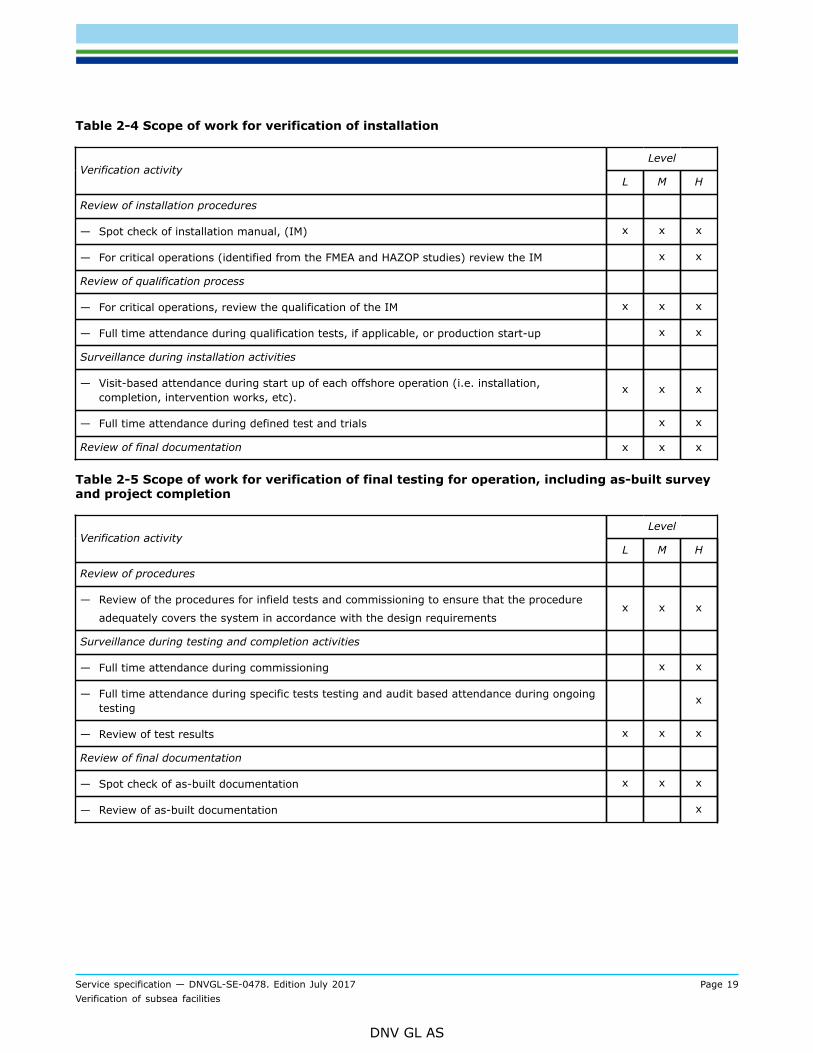
2.4.4.8 Definition of scope of work for verification of manufacturing and fabrication Table 2-3 and Table 2-4for installation and Table 2-5 for final testing and completion.

Service specification — DNVGL-SE-0478. Edition July 2017 Page 18Verification of subsea facilities
DNV GL AS
Table 2-3 Scope of work for verification of manufacturing and fabrication
LevelVerification activity
L M H
Review of the manufacturing and fabrication process
— Review of manufacturing and fabrication management systems x x x
— Audit of the quality management system (x) x
Review of manufacturing and fabrication procedures
— Review manufacturing, fabrication and inspection procedures for confirmation of compliancewith the manufacturing specification
x x x
— Review method statements x x
Review of qualification process
— Review the manufacturing procedure specification, (MPS), manufacturing procedurequalification test (MPQT), as applicable
x x x
— Full time attendance during MPQT, as applicable, or first day production x x
Surveillance during manufacturing and fabrication activities
— Visit-based attendance during testing, to ensure, based on spot checks, that the deliveredproducts have been produced in accordance with the
manufacturing specificationx x x
— Visit-based or full-time attendance during manufacturing and fabrication to ensure, based onspot checks, that the delivered products have been produced in accordance with the
manufacturing specification x x
— Full-time attendance during manufacturing and fabrication to ensure, based on spot checks,that the delivered products have been produced in
accordance with the manufacturing specification x
Review of final documentation x x x
Guidance note:Materials may be ordered with certificates of varying degrees of independent 3rd party verification (e.g. 3.1C according to EN10204). This can this be integrated in the overall verification activities, so not to duplicate work.
---e-n-d---o-f---g-u-i-d-a-n-c-e---n-o-t-e---
Service specification — DNVGL-SE-0478. Edition July 2017 Page 19Verification of subsea facilities
DNV GL AS
Table 2-4 Scope of work for verification of installation
LevelVerification activity
L M H
Review of installation procedures
— Spot check of installation manual, (IM) x x x
— For critical operations (identified from the FMEA and HAZOP studies) review the IM x x
Review of qualification process
— For critical operations, review the qualification of the IM x x x
— Full time attendance during qualification tests, if applicable, or production start-up x x
Surveillance during installation activities
— Visit-based attendance during start up of each offshore operation (i.e. installation,completion, intervention works, etc).
x x x
— Full time attendance during defined test and trials x x
Review of final documentation x x x
Table 2-5 Scope of work for verification of final testing for operation, including as-built surveyand project completion
LevelVerification activity
L M H
Review of procedures
— Review of the procedures for infield tests and commissioning to ensure that the procedure
adequately covers the system in accordance with the design requirementsx x x
Surveillance during testing and completion activities
— Full time attendance during commissioning x x
— Full time attendance during specific tests testing and audit based attendance during ongoingtesting
x
— Review of test results x x x
Review of final documentation
— Spot check of as-built documentation x x x
— Review of as-built documentation x
Service specification — DNVGL-SE-0478. Edition July 2017 Page 20Verification of subsea facilities
DNV GL AS
2.5 Project operation
2.5.1 Verification during operation
2.5.1.1 Verification during operation is carried out by audit or spot check of the work in sufficient detail toensure that the specified requirements of the subsea facilities continue to be achieved.
2.5.1.2 Assessment of these activities will relate to the owner’s, as well as any contractor’s, work.
2.5.1.3 During operations, these assessments should consist of:
— review of operations processes:
— review of operations management systems— audit of the quality management system, if necessary
— review of operations specifications and procedures:
— confirmation of design assumptions— method statements— inspection plans— inspection methods— procedures for evaluation of inspection results
— attendance during operations activities:
— attendance during inspections— review of inspection records.
2.5.1.4 In order to be able to carry out periodical surveys, the minimum documentation should include:
— personnel responsible for the operation of the subsea facilities— history of the subsea facilities operation with reference to events that may have significance with respect
to safety and functionality— installation condition data as required— physical and chemical characteristics of transported media including sand and sand detection measures— inspection and maintenance/intervention philosophy, schedules and records— inspection/intervention procedures and results as appropriate.
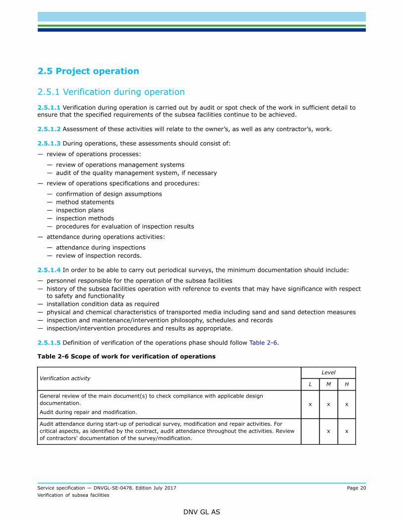
2.5.1.5 Definition of verification of the operations phase should follow Table 2-6.
Table 2-6 Scope of work for verification of operations
LevelVerification activity
L M H
General review of the main document(s) to check compliance with applicable designdocumentation.
Audit during repair and modification.x x x
Audit attendance during start-up of periodical survey, modification and repair activities. Forcritical aspects, as identified by the contract, audit attendance throughout the activities. Reviewof contractors' documentation of the survey/modification.
x x
Service specification — DNVGL-SE-0478. Edition July 2017 Page 21Verification of subsea facilities
DNV GL AS
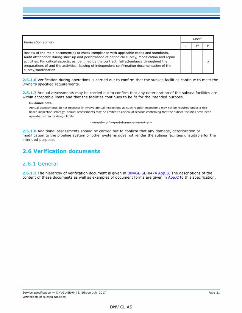
LevelVerification activity
L M H
Review of the main document(s) to check compliance with applicable codes and standards.Audit attendance during start-up and performance of periodical survey, modification and repairactivities. For critical aspects, as identified by the contract, full attendance throughout thepreparations of and the activities. Issuing of independent confirmation documentation of thesurvey/modification.
x
2.5.1.6 Verification during operations is carried out to confirm that the subsea facilities continue to meet theOwner’s specified requirements.
2.5.1.7 Annual assessments may be carried out to confirm that any deterioration of the subsea facilities arewithin acceptable limits and that the facilities continues to be fit for the intended purpose.
Guidance note:Annual assessments do not necessarily involve annual inspections as such regular inspections may not be required under a risk-based inspection strategy. Annual assessments may be limited to review of records confirming that the subsea facilities have beenoperated within its design limits.
---e-n-d---o-f---g-u-i-d-a-n-c-e---n-o-t-e---
2.5.1.8 Additional assessments should be carried out to confirm that any damage, deterioration ormodification to the pipeline system or other systems does not render the subsea facilities unsuitable for theintended purpose.
2.6 Verification documents
2.6.1 General
2.6.1.1 The hierarchy of verification document is given in DNVGL-SE-0474 App.B. The descriptions of thecontent of these documents as well as examples of document forms are given in App.C to this specification.
Service specification — DNVGL-SE-0478. Edition July 2017 Page 22Verification of subsea facilities
DNV GL AS
APPENDIX A SELECTION OF VERIFICATION LEVEL
A.1 General
A.1.1 General principles
A.1.1.1 The selection of the level of verification depends on the risk level of each of the elements that havean impact on the management of risks to the asset.
A.1.1.2 Verification shall direct greatest effort at those elements of the asset where the risk is highest andwhose failure or reduced performance will have the most significant impact on the project objective andgoals, e.g.:
— safety risks— environmental risks— economic risks.
A.1.1.3 Suitable selection factors include, but are not limited to, the:
— overall safety and other objectives for the asset— assessment of the risks associated with the asset and the measures taken to reduce these risks— degree of technical innovation in the asset— experience of the contractors in carrying out the work— quality management systems of the owner and its contractors.
A.1.1.4 Due to the diversity of various subsea systems, their contents, their degree of innovation, thegeographic location, et cetera, it is not possible to give precise guidelines on how to decide what level ofverification is appropriate for each particular subsea system.
A.1.1.5 Therefore, guidance is given as a series of questions that should be answered when deciding theappropriate level of verification for a subsea system. This list is not exhaustive and other questions should beadded to the list if appropriate for a particular subsea system.
A.1.1.6 It must be emphasised that the contribution of each element should be judged qualitatively and/or quantitatively. Wherever possible quantified risk assessment data should be used to provide a justifiablebasis for any decisions made.
A.1.1.7 Depending of the stage of the project, the activities may not have taken place yet in which case thequestions can also be posed in another form, i.e. Is …. planned to be?
A.2 Trigger questions
A.2.1 Overall project objective and goals— Does the safety objective address the main safety goals?— Does the safety objective establish acceptance criteria for the level of risk acceptable to the owner?— Is this risk (depending on the subsea system and its location) measured in terms of human injuries as
well as environmental, economic and political consequences?Guidance note:Substitute safety objective with other relevant objectives for the project, and go through all of them.
---e-n-d---o-f---g-u-i-d-a-n-c-e---n-o-t-e---

Service specification — DNVGL-SE-0478. Edition July 2017 Page 23Verification of subsea facilities
DNV GL AS
A.2.2 Assessment of risk— Has a systematic review been carried out to identify and evaluate the probabilities and consequences of
failures in the subsea system?— Has this review judged the contribution of each element qualitatively and/or quantitatively and used,
where possible, quantified risk assessment data to provide a justifiable basis for any decisions made?— Does the extent of the review reflect the risk level of the subsea system, the planned operation and
previous experience with similar subsea systems?— Does this review identify the risk to the operation of the subsea system and to the health and safety of
personnel associated with it or in its vicinity?— Has the extent of the identified risks been reduced to a level as low as reasonably practicable by means of
one or both of:
— Reduction in the probability of failure?— Mitigation of the consequences of failure?
— Has the result of the systematic review of the risks been measured against the owner’s safety (or other)objective?
— Has the result of this review been used in the selection of the appropriate verification activity level?
A.2.3 Technical innovation— Has the degree of technical innovation in the subsea system been considered?— Has it been considered that risks to the subsea system are likely to be greater with a high degree of
technical innovation than with a subsea system designed, manufactured and installed to well-knowncriteria in well-known waters?
— Have factors been considered in the selection of the appropriate verification level such as:
— degree of difficulty in achieving technical requirements— knowledge of similar subsea systems— effect of the new subsea system on the surrounding area.
A.2.4 Contractors’ experience— Has the degree of risk to the subsea system been considered where design, construction or installation
contractors are inexperienced?— Has the degree of risk been considered where the contractors are experienced but not in similar work?— Has the degree of risk been considered where the work schedule is tight?
Service specification — DNVGL-SE-0478. Edition July 2017 Page 24Verification of subsea facilities
DNV GL AS
A.2.5 Quality management systems— Have all parties involved in the subsea system implemented an adequate quality management system to
ensure that gross errors in the work are limited?— Do these parties include the:
— Owner?— Design contractor?— Construction contractors?— Installation contractor?— Operator?
— Do the factors being considered when evaluating the adequacy of the quality management systeminclude:
— Whether or not an ISO 9000 or equivalent certified system is in place?— Results from external audits?— Results from internal audits?— Experience with contractors’ previous work?— Project work force familiarity with the quality management system?
Service specification — DNVGL-SE-0478. Edition July 2017 Page 25Verification of subsea facilities
DNV GL AS
APPENDIX B DETAILED EXAMPLE SCOPE OF WORK TABLES FORVERIFICATION
B.1 General
B.1.1 General introduction
B.1.1.1 This appendix provides the format of the detailed verification lists (tables), generated for typicalsystems comprising a subsea facility:
1) downhole system2) subsea wellhead and tree system (including: choke, tubing hanger and connection systems)3) manifold, foundations and template4) flowlines and risers (including dynamic umbilical risers)5) subsea control umbilicals6) subsea production control system7) subsea processing system8) well intervention/completion/workover system9) ROT intervention systems.
which shall be made for each particular project.
B.1.1.2 The detailed project-specific verification lists for the chosen level of verification shall be based onthese tables. For project scenarios or components not covered in this appendix, similar lists with the samedegree of detail shall be made.
Guidance note:Descriptions of these systems can be found on top of the design tables.
---e-n-d---o-f---g-u-i-d-a-n-c-e---n-o-t-e---
B.1.1.3 If any of the activities are moved from one phase to another, then this must be identified clearlyidentified on the list where it is removed. Similarly, the detailed list for the phase to where it is moved shallbe amended.
Guidance note:Typically, contractual boundaries may give natural splits of activities between phases. However, then it is then even more importantto ensure that there is a traceably as to which phases what activity belong and that this is also conveyed to the contractors also.
---e-n-d---o-f---g-u-i-d-a-n-c-e---n-o-t-e---
B.2 Description of terms used in the verification lists
B.2.1 General
B.2.1.1 The following abbreviations have been used. The definition contents of which are given subsequentlygiven:
A = auditS = surveillanceH = hold pointR = review
Service specification — DNVGL-SE-0478. Edition July 2017 Page 26Verification of subsea facilities
DNV GL AS
B.2.1.2 These abbreviations are DNV GL’s preferred terms and will normally be used in DNV GL-generateddocuments. However, other terms, for example monitoring or witnessing, will be used by DNV GL if theseare the terms commonly used in documents, such as inspection and test plans, generated by others. In thatcase, it is expected that these other terms are defined in these documents.
B.2.2 Audit
B.2.2.1 Systematic and independent examination to determine whether quality activities and related resultscomply with planned arrangements and whether these arrangements are implemented effectively and aresuitable to achieve objectives (ISO 8402:1994).
Guidance note:This activity differs from the surveillance by being focused on the adherence to and completeness and robustness of theprocedures and not on the actual result of the procedure (although this is not ignored). Further, the audit is normally a one-offactivity as opposed to the continuity in monitoring.
---e-n-d---o-f---g-u-i-d-a-n-c-e---n-o-t-e---
B.2.3 Surveillance
B.2.3.1 Continual monitoring and verification of the status of an entity and analysis of records to ensure thatspecified requirements are being fulfilled (ISO 8402:1994).
Guidance note:Other commonly used terms for surveillance are monitoring or witnessing.
---e-n-d---o-f---g-u-i-d-a-n-c-e---n-o-t-e---
B.2.3.2 The amount of work involved in surveillance is not described in detail in the tables. This shall be partof the final contractual scope of work which shall define the frequency of surveillance based on the overallsurveillance and the quality control performed by other parties as well as DNV GL’s experience.
B.2.3.3 The following shall be used to describe the frequency if nothing else is specifically defined:
S1 = surveillance on a visit basis, e.g. frequency minimum once per week
S2 = surveillance frequency minimum once per day
S3 = surveillance frequency minimum once per shift.
Guidance note:These surveillance frequencies may be modified to correspond with production work flow.
---e-n-d---o-f---g-u-i-d-a-n-c-e---n-o-t-e---
B.2.4 Hold point witnessing
B.2.4.1 A point, defined in an appropriate document, beyond which an activity must not proceed without theapproval of a designated organization or authority (ISO 8402:1994).
B.2.5 Review
B.2.5.1 Systematic examination of reports and documentation. The depth of review will depend both on thetype of document and the level of involvement.

Service specification — DNVGL-SE-0478. Edition July 2017 Page 27Verification of subsea facilities
DNV GL AS
B.2.5.2 The following shall be used to describe the extent of the review if nothing else is specifically defined:
I = for information only
R1 = review of principles and general aspects
R2 = comprehensive review
Guidance note:Review of production records does not guarantee their correctness. It is a confirmation to DNV GL that the manufacturer and/orsub-contractor has preformed the required activity and issued a report.
---e-n-d---o-f---g-u-i-d-a-n-c-e---n-o-t-e---
B.2.5.3 Documents that are reviewed by DNV GL will, unless otherwise agreed, not be signed and stamped.
B.3 Overall project management
B.3.1 General
B.3.1.1 The project quality management documentation, if part of scope, should be available at the earlystages of the project, preferably before design is underway, to ensure that the necessary controls are inplace.
Table B-1 Overall project management
LevelItem Description
Low Medium High
1 review of project quality management documentation. R1 R2 R2
2 audit of project quality management system R1 R2 R2
3 review of sub-contractor control R1 R2 R2
4 review of interface controls R1 R2 R2
5 review of methods of information flow R1
B.4 Design
B.4.1 General
B.4.1.1 For design verification a list similar to that given in Table B-2 to Table B-11 shall be made for thespecifics of the minimum requirement to documentation for each subsea facility.
B.4.2 Design verification
B.4.2.1 Table B-2 to Table B-11describe issues to be verified. Table B-12 to Table B-20 identifies relevantindependent analyses/calculations included in the three verification levels.
Service specification — DNVGL-SE-0478. Edition July 2017 Page 28Verification of subsea facilities
DNV GL AS
B.4.3 Low level design verification
B.4.3.1 The initial low level design verification consists of a detailed document review of the design basis,risk assessment/analysis documentation, quality management documentation and (if they exist) methodor design philosophy documents. The presumed high risk aspects of the project shall be identified by DNVGL from the initial review and conveyed to the owner and designer for discussion and agreement on correctunderstanding.
B.4.3.2 The subsequent verification consists of document review of the calculations analysis methods usedto conclude the high risk aspects. Other design documents are used as information and a few will be spotchecked for confirmation of the quality control.
B.4.3.3 Implementation of the transfer of conclusions from design calculations and or reports into drawingsand specifications is not included.
B.4.4 Medium level design verification
B.4.4.1 Medium level design verification consists of a review of all main design documents related to subseafacilities safety and integrity. Less critical aspects will be spot checked. The review will be detailed for highrisk aspects and independent checks will be performed.
B.4.4.2 A design quality management system audit will be performed.
B.4.4.3 Implementation of the conclusions from design calculations/reports into drawings and specificationswill be or is included on a spot check basis.
B.4.5 High level design verification
B.4.5.1 High level design verification consists of a full review of most of the produced documents related tointegrity. The review will be detailed for all high risk aspects and independent checks shall be performed.
B.4.5.2 Implementation of the conclusions from design calculations reports into drawings and specificationsis included.
Service specification — DNVGL-SE-0478. Edition July 2017 Page 29Verification of subsea facilities
DNV GL AS
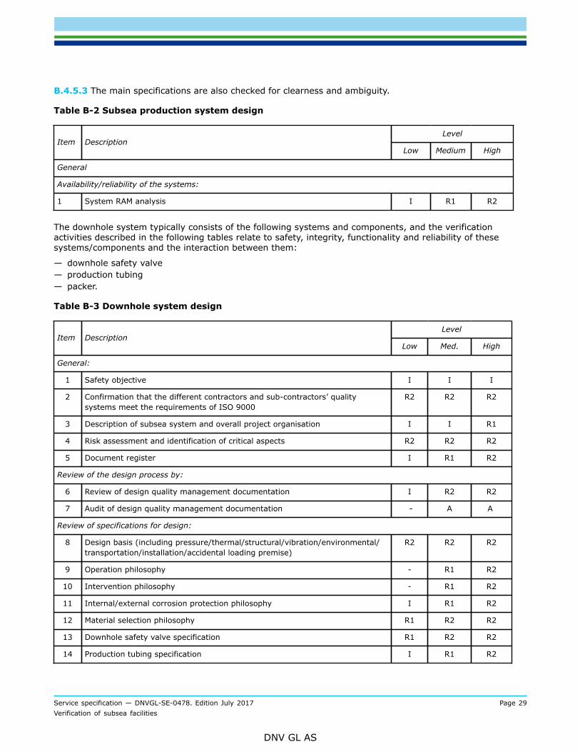
B.4.5.3 The main specifications are also checked for clearness and ambiguity.
Table B-2 Subsea production system design
LevelItem Description
Low Medium High
General
Availability/reliability of the systems:
1 System RAM analysis I R1 R2
The downhole system typically consists of the following systems and components, and the verificationactivities described in the following tables relate to safety, integrity, functionality and reliability of thesesystems/components and the interaction between them:
— downhole safety valve— production tubing— packer.
Table B-3 Downhole system design
LevelItem Description
Low Med. High
General:
1 Safety objective I I I
2 Confirmation that the different contractors and sub-contractors’ qualitysystems meet the requirements of ISO 9000
R2 R2 R2
3 Description of subsea system and overall project organisation I I R1
4 Risk assessment and identification of critical aspects R2 R2 R2
5 Document register I R1 R2
Review of the design process by:
6 Review of design quality management documentation I R2 R2
7 Audit of design quality management documentation - A A
Review of specifications for design:
8 Design basis (including pressure/thermal/structural/vibration/environmental/transportation/installation/accidental loading premise)
R2 R2 R2
9 Operation philosophy - R1 R2
10 Intervention philosophy - R1 R2
11 Internal/external corrosion protection philosophy I R1 R2
12 Material selection philosophy R1 R2 R2
13 Downhole safety valve specification R1 R2 R2
14 Production tubing specification I R1 R2
Service specification — DNVGL-SE-0478. Edition July 2017 Page 30Verification of subsea facilities
DNV GL AS
LevelItem Description
Low Med. High
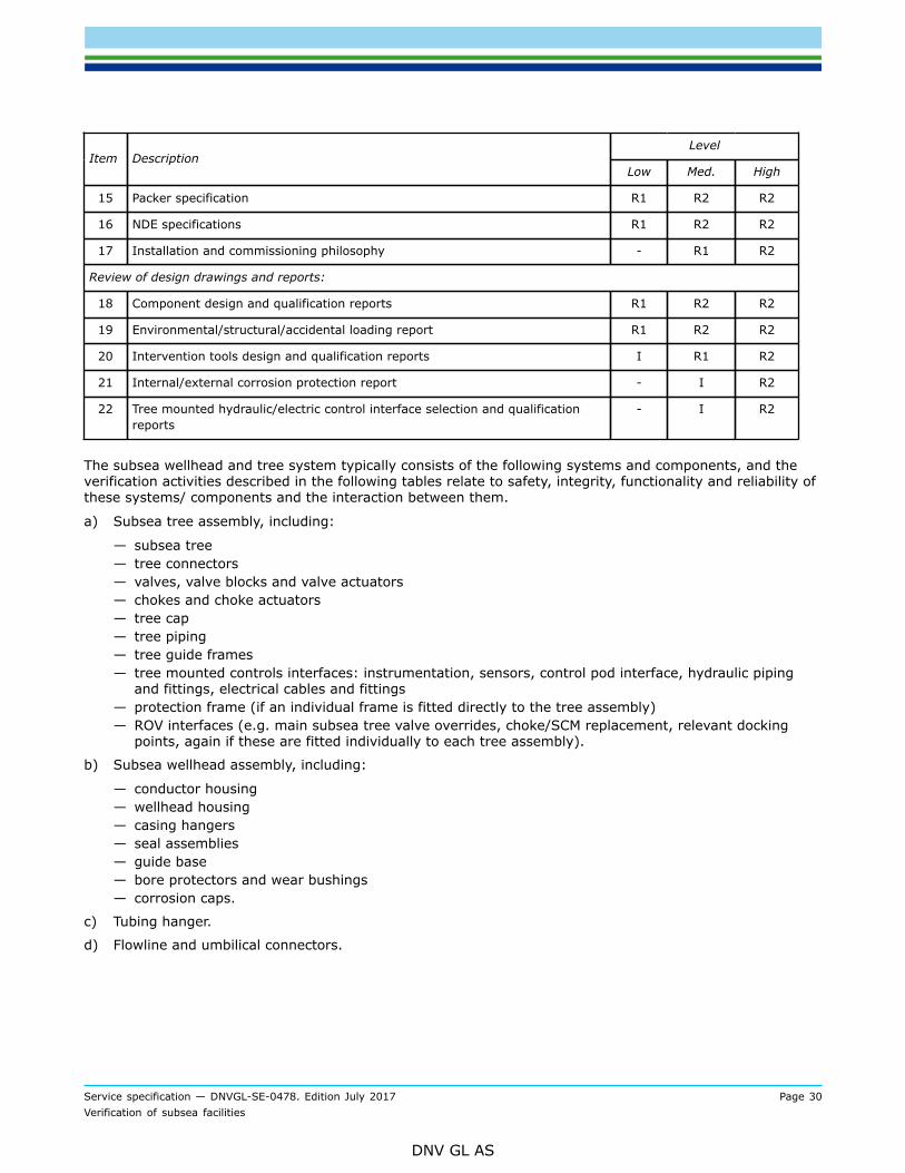
15 Packer specification R1 R2 R2
16 NDE specifications R1 R2 R2
17 Installation and commissioning philosophy - R1 R2
Review of design drawings and reports:
18 Component design and qualification reports R1 R2 R2
19 Environmental/structural/accidental loading report R1 R2 R2
20 Intervention tools design and qualification reports I R1 R2
21 Internal/external corrosion protection report - I R2
22 Tree mounted hydraulic/electric control interface selection and qualificationreports
- I R2
The subsea wellhead and tree system typically consists of the following systems and components, and theverification activities described in the following tables relate to safety, integrity, functionality and reliability ofthese systems/ components and the interaction between them.
a) Subsea tree assembly, including:
— subsea tree— tree connectors— valves, valve blocks and valve actuators— chokes and choke actuators— tree cap— tree piping— tree guide frames— tree mounted controls interfaces: instrumentation, sensors, control pod interface, hydraulic piping
and fittings, electrical cables and fittings— protection frame (if an individual frame is fitted directly to the tree assembly)— ROV interfaces (e.g. main subsea tree valve overrides, choke/SCM replacement, relevant docking
points, again if these are fitted individually to each tree assembly).
b) Subsea wellhead assembly, including:
— conductor housing— wellhead housing— casing hangers— seal assemblies— guide base— bore protectors and wear bushings— corrosion caps.
c) Tubing hanger.
d) Flowline and umbilical connectors.
Service specification — DNVGL-SE-0478. Edition July 2017 Page 31Verification of subsea facilities
DNV GL AS
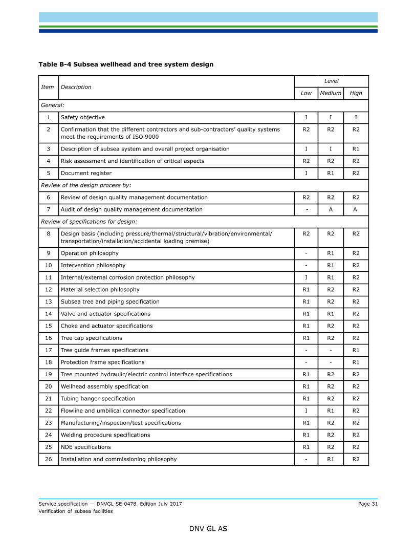
Table B-4 Subsea wellhead and tree system design
LevelItem Description
Low Medium High
General:
1 Safety objective I I I
2 Confirmation that the different contractors and sub-contractors’ quality systemsmeet the requirements of ISO 9000
R2 R2 R2
3 Description of subsea system and overall project organisation I I R1
4 Risk assessment and identification of critical aspects R2 R2 R2
5 Document register I R1 R2
Review of the design process by:
6 Review of design quality management documentation R2 R2 R2
7 Audit of design quality management documentation - A A
Review of specifications for design:
8 Design basis (including pressure/thermal/structural/vibration/environmental/transportation/installation/accidental loading premise)
R2 R2 R2
9 Operation philosophy - R1 R2
10 Intervention philosophy - R1 R2
11 Internal/external corrosion protection philosophy I R1 R2
12 Material selection philosophy R1 R2 R2
13 Subsea tree and piping specification R1 R2 R2
14 Valve and actuator specifications R1 R1 R2
15 Choke and actuator specifications R1 R2 R2
16 Tree cap specifications R1 R2 R2
17 Tree guide frames specifications - - R1
18 Protection frame specifications - - R1
19 Tree mounted hydraulic/electric control interface specifications R1 R2 R2
20 Wellhead assembly specification R1 R2 R2
21 Tubing hanger specification R1 R2 R2
22 Flowline and umbilical connector specification I R1 R2
23 Manufacturing/inspection/test specifications R1 R2 R2
24 Welding procedure specifications R1 R2 R2
25 NDE specifications R1 R2 R2
26 Installation and commissioning philosophy - R1 R2
Service specification — DNVGL-SE-0478. Edition July 2017 Page 32Verification of subsea facilities
DNV GL AS
LevelItem Description
Low Medium High
Review of design drawings and reports:
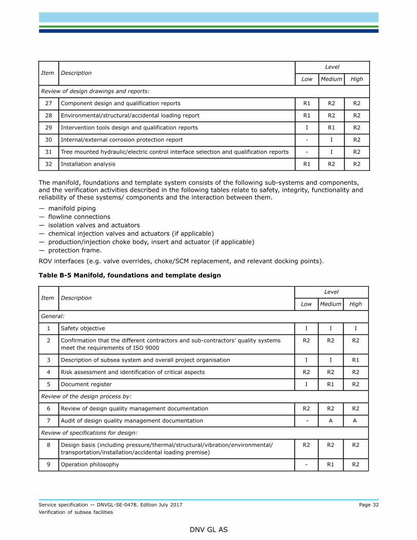
27 Component design and qualification reports R1 R2 R2
28 Environmental/structural/accidental loading report R1 R2 R2
29 Intervention tools design and qualification reports I R1 R2
30 Internal/external corrosion protection report - I R2
31 Tree mounted hydraulic/electric control interface selection and qualification reports - I R2
32 Installation analysis R1 R2 R2
The manifold, foundations and template system consists of the following sub-systems and components,and the verification activities described in the following tables relate to safety, integrity, functionality andreliability of these systems/ components and the interaction between them.
— manifold piping— flowline connections— isolation valves and actuators— chemical injection valves and actuators (if applicable)— production/injection choke body, insert and actuator (if applicable)— protection frame.
ROV interfaces (e.g. valve overrides, choke/SCM replacement, and relevant docking points).
Table B-5 Manifold, foundations and template design
LevelItem Description
Low Medium High
General:
1 Safety objective I I I
2 Confirmation that the different contractors and sub-contractors’ quality systemsmeet the requirements of ISO 9000
R2 R2 R2
3 Description of subsea system and overall project organisation I I R1
4 Risk assessment and identification of critical aspects R2 R2 R2
5 Document register I R1 R2
Review of the design process by:
6 Review of design quality management documentation R2 R2 R2
7 Audit of design quality management documentation - A A
Review of specifications for design:
8 Design basis (including pressure/thermal/structural/vibration/environmental/transportation/installation/accidental loading premise)
R2 R2 R2
9 Operation philosophy - R1 R2
Service specification — DNVGL-SE-0478. Edition July 2017 Page 33Verification of subsea facilities
DNV GL AS
LevelItem Description
Low Medium High
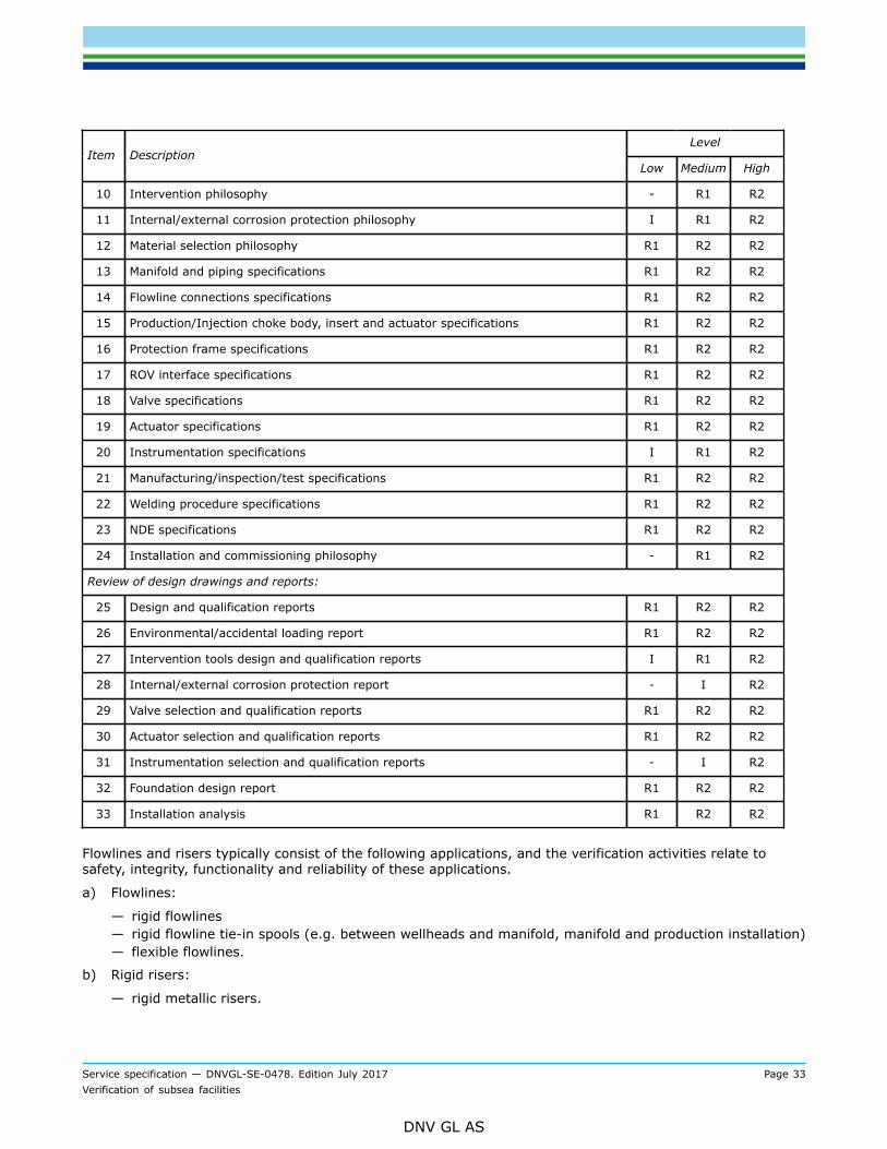
10 Intervention philosophy - R1 R2
11 Internal/external corrosion protection philosophy I R1 R2
12 Material selection philosophy R1 R2 R2
13 Manifold and piping specifications R1 R2 R2
14 Flowline connections specifications R1 R2 R2
15 Production/Injection choke body, insert and actuator specifications R1 R2 R2
16 Protection frame specifications R1 R2 R2
17 ROV interface specifications R1 R2 R2
18 Valve specifications R1 R2 R2
19 Actuator specifications R1 R2 R2
20 Instrumentation specifications I R1 R2
21 Manufacturing/inspection/test specifications R1 R2 R2
22 Welding procedure specifications R1 R2 R2
23 NDE specifications R1 R2 R2
24 Installation and commissioning philosophy - R1 R2
Review of design drawings and reports:
25 Design and qualification reports R1 R2 R2
26 Environmental/accidental loading report R1 R2 R2
27 Intervention tools design and qualification reports I R1 R2
28 Internal/external corrosion protection report - I R2
29 Valve selection and qualification reports R1 R2 R2
30 Actuator selection and qualification reports R1 R2 R2
31 Instrumentation selection and qualification reports - I R2
32 Foundation design report R1 R2 R2
33 Installation analysis R1 R2 R2
Flowlines and risers typically consist of the following applications, and the verification activities relate tosafety, integrity, functionality and reliability of these applications.
a) Flowlines:
— rigid flowlines— rigid flowline tie-in spools (e.g. between wellheads and manifold, manifold and production installation)— flexible flowlines.
b) Rigid risers:
— rigid metallic risers.
Service specification — DNVGL-SE-0478. Edition July 2017 Page 34Verification of subsea facilities
DNV GL AS
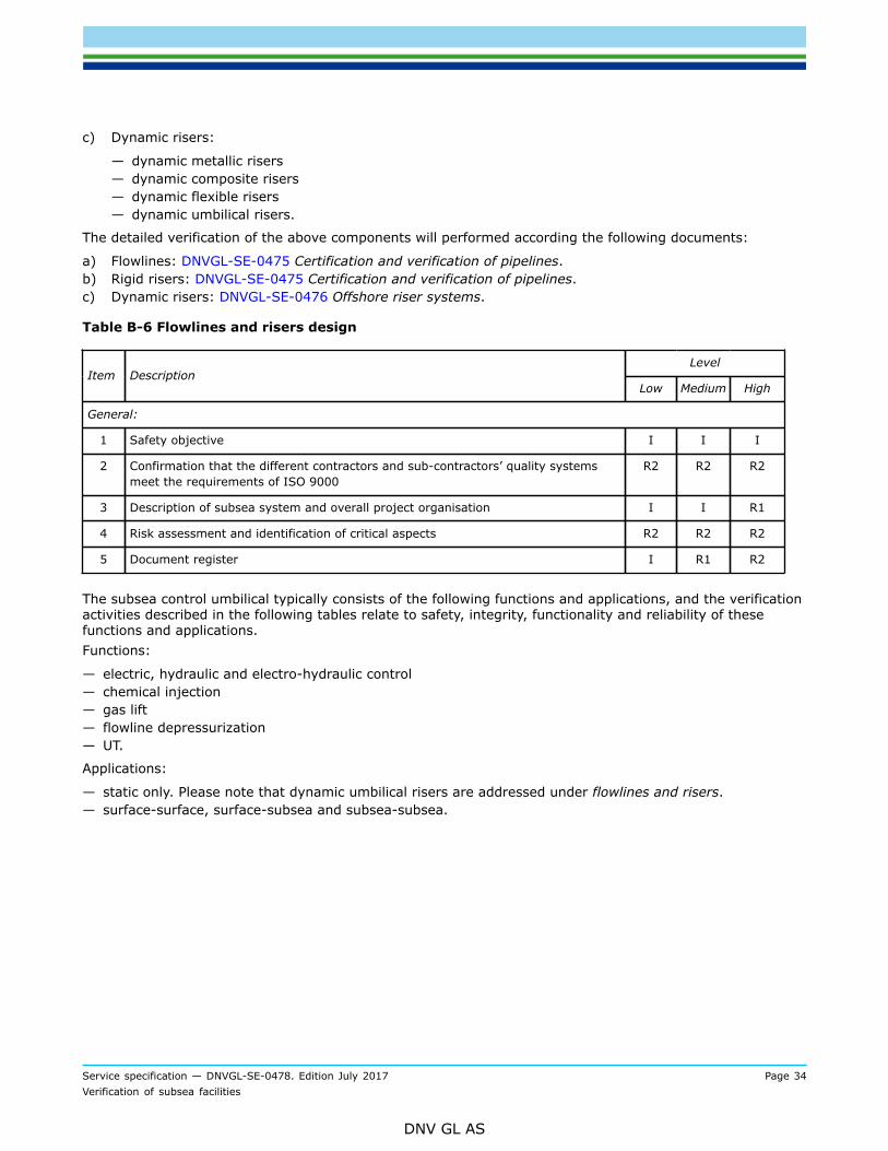
c) Dynamic risers:
— dynamic metallic risers— dynamic composite risers— dynamic flexible risers— dynamic umbilical risers.
The detailed verification of the above components will performed according the following documents:
a) Flowlines: DNVGL-SE-0475 Certification and verification of pipelines.b) Rigid risers: DNVGL-SE-0475 Certification and verification of pipelines.c) Dynamic risers: DNVGL-SE-0476 Offshore riser systems.
Table B-6 Flowlines and risers design
LevelItem Description
Low Medium High
General:
1 Safety objective I I I
2 Confirmation that the different contractors and sub-contractors’ quality systemsmeet the requirements of ISO 9000
R2 R2 R2
3 Description of subsea system and overall project organisation I I R1
4 Risk assessment and identification of critical aspects R2 R2 R2
5 Document register I R1 R2
The subsea control umbilical typically consists of the following functions and applications, and the verificationactivities described in the following tables relate to safety, integrity, functionality and reliability of thesefunctions and applications.Functions:
— electric, hydraulic and electro-hydraulic control— chemical injection— gas lift— flowline depressurization— UT.
Applications:
— static only. Please note that dynamic umbilical risers are addressed under flowlines and risers.— surface-surface, surface-subsea and subsea-subsea.
Service specification — DNVGL-SE-0478. Edition July 2017 Page 35Verification of subsea facilities
DNV GL AS
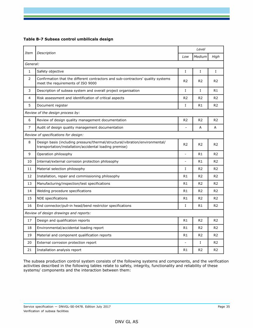
Table B-7 Subsea control umbilicals design
LevelItem Description
Low Medium High
General:
1 Safety objective I I I
2 Confirmation that the different contractors and sub-contractors’ quality systemsmeet the requirements of ISO 9000 R2 R2 R2
3 Description of subsea system and overall project organisation I I R1
4 Risk assessment and identification of critical aspects R2 R2 R2
5 Document register I R1 R2
Review of the design process by:
6 Review of design quality management documentation R2 R2 R2
7 Audit of design quality management documentation - A A
Review of specifications for design:
8 Design basis (including pressure/thermal/structural/vibration/environmental/transportation/installation/accidental loading premise) R2 R2 R2
9 Operation philosophy - R1 R2
10 Internal/external corrosion protection philosophy - R1 R2
11 Material selection philosophy I R2 R2
12 Installation, repair and commissioning philosophy R1 R2 R2
13 Manufacturing/inspection/test specifications R1 R2 R2
14 Welding procedure specifications R1 R2 R2
15 NDE specifications R1 R2 R2
16 End connector/pull-in head/bend restrictor specifications I R1 R2
Review of design drawings and reports:
17 Design and qualification reports R1 R2 R2
18 Environmental/accidental loading report R1 R2 R2
19 Material and component qualification reports R1 R2 R2
20 External corrosion protection report - I R2
21 Installation analysis report R1 R2 R2
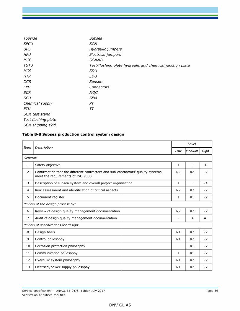
The subsea production control system consists of the following systems and components, and the verificationactivities described in the following tables relate to safety, integrity, functionality and reliability of thesesystems/ components and the interaction between them:
Service specification — DNVGL-SE-0478. Edition July 2017 Page 36Verification of subsea facilities
DNV GL AS
TopsideSPCUUPSHPUMCCTUTUMCSHTPDCSEPUSCRSCUChemical supplyETUSCM test standTest flushing plateSCM shipping skid
SubseaSCMHydraulic jumpersElectrical jumpersSCMMBTest/flushing plate hydraulic and chemical junction plateSDUEDUSensorsConnectorsMQCSEMPTTT
Table B-8 Subsea production control system design
LevelItem Description
Low Medium High
General:
1 Safety objective I I I
2 Confirmation that the different contractors and sub-contractors’ quality systemsmeet the requirements of ISO 9000
R2 R2 R2
3 Description of subsea system and overall project organisation I I R1
4 Risk assessment and identification of critical aspects R2 R2 R2
5 Document register I R1 R2
Review of the design process by:
6 Review of design quality management documentation R2 R2 R2
7 Audit of design quality management documentation - A A
Review of specifications for design:
8 Design basis R1 R2 R2
9 Control philosophy R1 R2 R2
10 Corrosion protection philosophy - R1 R2
11 Communication philosophy I R1 R2
12 Hydraulic system philosophy R1 R2 R2
13 Electrical/power supply philosophy R1 R2 R2
Service specification — DNVGL-SE-0478. Edition July 2017 Page 37Verification of subsea facilities
DNV GL AS
LevelItem Description
Low Medium High
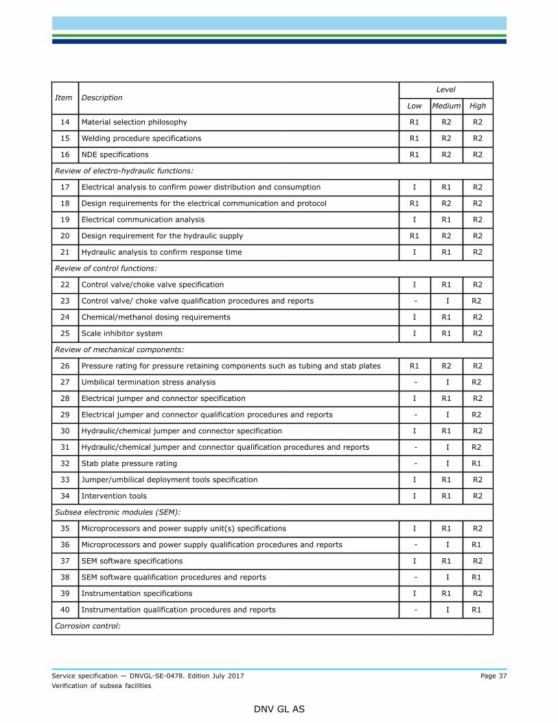
14 Material selection philosophy R1 R2 R2
15 Welding procedure specifications R1 R2 R2
16 NDE specifications R1 R2 R2
Review of electro-hydraulic functions:
17 Electrical analysis to confirm power distribution and consumption I R1 R2
18 Design requirements for the electrical communication and protocol R1 R2 R2
19 Electrical communication analysis I R1 R2
20 Design requirement for the hydraulic supply R1 R2 R2
21 Hydraulic analysis to confirm response time I R1 R2
Review of control functions:
22 Control valve/choke valve specification I R1 R2
23 Control valve/ choke valve qualification procedures and reports - I R2
24 Chemical/methanol dosing requirements I R1 R2
25 Scale inhibitor system I R1 R2
Review of mechanical components:
26 Pressure rating for pressure retaining components such as tubing and stab plates R1 R2 R2
27 Umbilical termination stress analysis - I R2
28 Electrical jumper and connector specification I R1 R2
29 Electrical jumper and connector qualification procedures and reports - I R2
30 Hydraulic/chemical jumper and connector specification I R1 R2
31 Hydraulic/chemical jumper and connector qualification procedures and reports - I R2
32 Stab plate pressure rating - I R1
33 Jumper/umbilical deployment tools specification I R1 R2
34 Intervention tools I R1 R2
Subsea electronic modules (SEM):
35 Microprocessors and power supply unit(s) specifications I R1 R2
36 Microprocessors and power supply qualification procedures and reports - I R1
37 SEM software specifications I R1 R2
38 SEM software qualification procedures and reports - I R1
39 Instrumentation specifications I R1 R2
40 Instrumentation qualification procedures and reports - I R1
Corrosion control:
Service specification — DNVGL-SE-0478. Edition July 2017 Page 38Verification of subsea facilities
DNV GL AS
LevelItem Description
Low Medium High
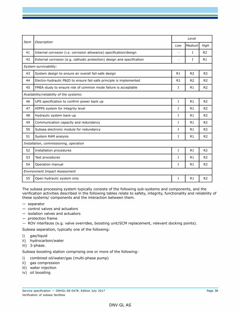
41 Internal corrosion (i.e. corrosion allowance) specification/design - I R2
42 External corrosion (e.g. cathodic protection) design and specification - I R1
System survivability:
43 System design to ensure an overall fail-safe design R1 R2 R2
44 Electro-hydraulic P&ID to ensure fail-safe principle is implemented R1 R2 R2
45 FMEA study to ensure risk of common mode failure is acceptable I R1 R2
Availability/reliability of the systems:
46 UPS specification to confirm power back up I R1 R2
47 HIPPS system for integrity level I R1 R2
48 Hydraulic system back-up I R1 R2
49 Communication capacity and redundancy I R1 R2
50 Subsea electronic module for redundancy I R1 R2
51 System RAM analysis I R1 R2
Installation, commissioning, operation
52 Installation procedures I R1 R2
53 Test procedures I R1 R2
54 Operation manual I R1 R2
Environment Impact Assessment
55 Open hydraulic system only I R1 R2
The subsea processing system typically consists of the following sub-systems and components, and theverification activities described in the following tables relate to safety, integrity, functionality and reliability ofthese systems/ components and the interaction between them.
— separator— control valves and actuators— isolation valves and actuators— protection frame— ROV interfaces (e.g. valve overrides, boosting unit/SCM replacement, relevant docking points).
Subsea separation, typically one of the following:
i) gas/liquidii) hydrocarbon/wateriii) 3-phase.
Subsea boosting station comprising one or more of the following:
i) combined oil/water/gas (multi-phase pump)ii) gas compressioniii) water injectioniv) oil boosting

Service specification — DNVGL-SE-0478. Edition July 2017 Page 39Verification of subsea facilities
DNV GL AS
v) oil/water boosting (multi-phase pump)vi) combined gas/water injection (multi-phase pump).
Table B-9 Subsea processing system design
LevelItem Description
Low Medium High
General
1 Safety objective I I I
2 Confirmation that the different contractors and sub-contractors’ quality systemsmeet the requirements of ISO 9000
R2 R2 R2
3 Description of subsea system and overall project organisation I I R1
4 Risk assessment and identification of critical aspects R2 R2 R2
5 Document register I R1 R2
Review of the design process by:
6 Review of design quality management documentation R2 R2 R2
7 Audit of design quality management documentation - A A
Review of specifications for design:
8 Design basis (including pressure/thermal/structural/vibration/environmental/transportation/installation/accidental loading premise)
R2 R2 R2
9 Operation philosophy I R1 R2
10 Installation and commissioning philosophy - R1 R2
11 Internal/external corrosion protection philosophy I R1 R2
12 Intervention philosophy I R1 R2
13 Material selection philosophy R1 R2 R2
14 Separator specifications R1 R2 R2
15 Boosting station specification {could split into smaller components e.g. pump,filter, cooler, seals, compressor, lube oil system, etc.}
R1 R2 R2
16 Valve/actuator specifications I R1 R2
17 Instrumentation specifications I R1 R2
18 Protection frame specifications I R1 R2
19 ROV interfaces specifications I R1 R2
20 Manufacturing/inspection/test specifications R1 R2 R2
21 Welding procedure specifications R1 R2 R2
22 NDE specifications R1 R2 R2
Review of design drawings and reports:
23 Design report R1 R2 R2
Service specification — DNVGL-SE-0478. Edition July 2017 Page 40Verification of subsea facilities
DNV GL AS
LevelItem Description
Low Medium High
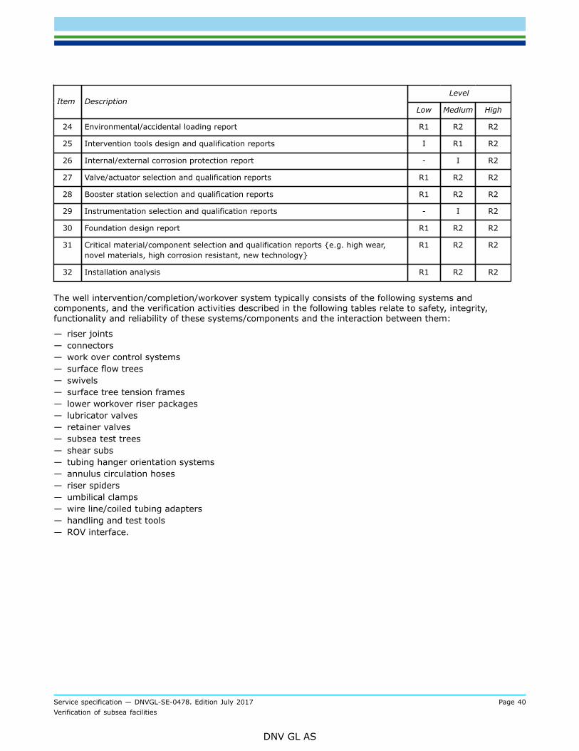
24 Environmental/accidental loading report R1 R2 R2
25 Intervention tools design and qualification reports I R1 R2
26 Internal/external corrosion protection report - I R2
27 Valve/actuator selection and qualification reports R1 R2 R2
28 Booster station selection and qualification reports R1 R2 R2
29 Instrumentation selection and qualification reports - I R2
30 Foundation design report R1 R2 R2
31 Critical material/component selection and qualification reports {e.g. high wear,novel materials, high corrosion resistant, new technology}
R1 R2 R2
32 Installation analysis R1 R2 R2
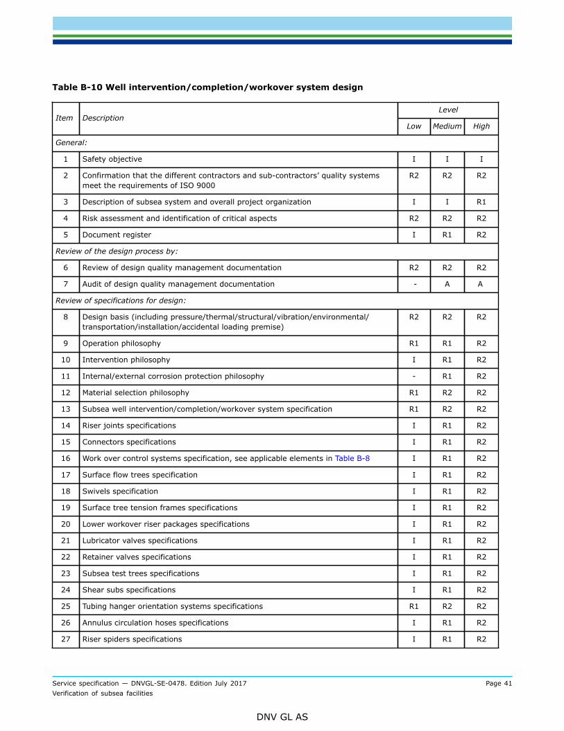
The well intervention/completion/workover system typically consists of the following systems andcomponents, and the verification activities described in the following tables relate to safety, integrity,functionality and reliability of these systems/components and the interaction between them:
— riser joints— connectors— work over control systems— surface flow trees— swivels— surface tree tension frames— lower workover riser packages— lubricator valves— retainer valves— subsea test trees— shear subs— tubing hanger orientation systems— annulus circulation hoses— riser spiders— umbilical clamps— wire line/coiled tubing adapters— handling and test tools— ROV interface.
Service specification — DNVGL-SE-0478. Edition July 2017 Page 41Verification of subsea facilities
DNV GL AS
Table B-10 Well intervention/completion/workover system design
LevelItem Description
Low Medium High
General:
1 Safety objective I I I
2 Confirmation that the different contractors and sub-contractors’ quality systemsmeet the requirements of ISO 9000
R2 R2 R2
3 Description of subsea system and overall project organization I I R1
4 Risk assessment and identification of critical aspects R2 R2 R2
5 Document register I R1 R2
Review of the design process by:
6 Review of design quality management documentation R2 R2 R2
7 Audit of design quality management documentation - A A
Review of specifications for design:
8 Design basis (including pressure/thermal/structural/vibration/environmental/transportation/installation/accidental loading premise)
R2 R2 R2
9 Operation philosophy R1 R1 R2
10 Intervention philosophy I R1 R2
11 Internal/external corrosion protection philosophy - R1 R2
12 Material selection philosophy R1 R2 R2
13 Subsea well intervention/completion/workover system specification R1 R2 R2
14 Riser joints specifications I R1 R2
15 Connectors specifications I R1 R2
16 Work over control systems specification, see applicable elements in Table B-8 I R1 R2
17 Surface flow trees specification I R1 R2
18 Swivels specification I R1 R2
19 Surface tree tension frames specifications I R1 R2
20 Lower workover riser packages specifications I R1 R2
21 Lubricator valves specifications I R1 R2
22 Retainer valves specifications I R1 R2
23 Subsea test trees specifications I R1 R2
24 Shear subs specifications I R1 R2
25 Tubing hanger orientation systems specifications R1 R2 R2
26 Annulus circulation hoses specifications I R1 R2
27 Riser spiders specifications I R1 R2
Service specification — DNVGL-SE-0478. Edition July 2017 Page 42Verification of subsea facilities
DNV GL AS
LevelItem Description
Low Medium High
28 Umbilical clamps specifications - R1 R2
29 Handling and test tools specification I R1 R2
30 Wire line/coiled tubing adapters specification I R1 R2
31 ROV interface specifications I R1 R2
32 Manufacturing/inspection/test specification R1 R2 R2
33 Welding procedure specification R1 R2 R2
34 NDE specifications R1 R2 R2
35 System design to ensure an overall fail-safe system R1 R1 R2
Review of design drawings and reports:
36 Component design and qualification reports R1 R2 R2
37 Environmental/structural/accidental loading report R1 R2 R2
38 Intervention tools design and qualification reports I R1 R2
39 Internal/external corrosion protection report - I R2
40 Tree mounted hydraulic/electric control interface selection and qualification reports - I R2
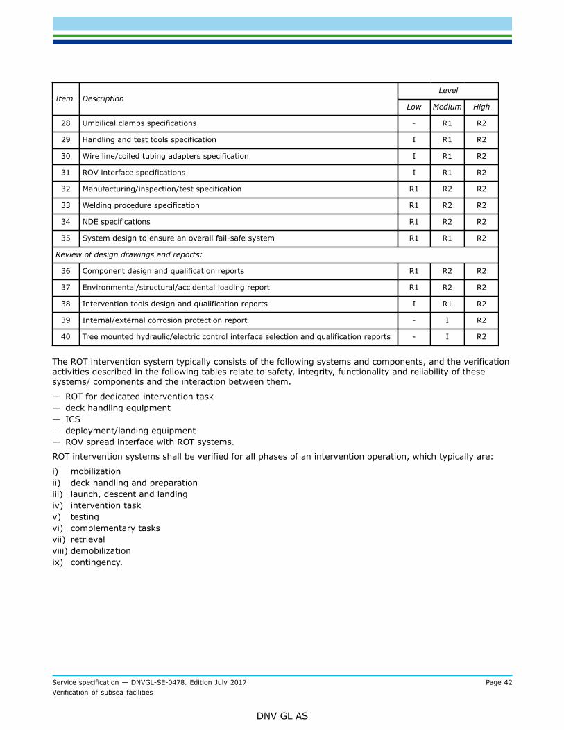
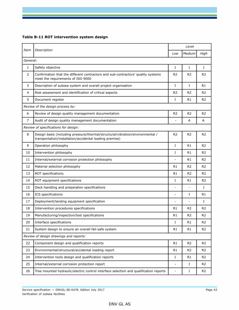
The ROT intervention system typically consists of the following systems and components, and the verificationactivities described in the following tables relate to safety, integrity, functionality and reliability of thesesystems/ components and the interaction between them.
— ROT for dedicated intervention task— deck handling equipment— ICS— deployment/landing equipment— ROV spread interface with ROT systems.
ROT intervention systems shall be verified for all phases of an intervention operation, which typically are:
i) mobilizationii) deck handling and preparationiii) launch, descent and landingiv) intervention taskv) testingvi) complementary tasksvii) retrievalviii) demobilizationix) contingency.
Service specification — DNVGL-SE-0478. Edition July 2017 Page 43Verification of subsea facilities
DNV GL AS
Table B-11 ROT intervention system design
LevelItem Description
Low Medium High
General:
1 Safety objective I I I
2 Confirmation that the different contractors and sub-contractors’ quality systemsmeet the requirements of ISO 9000
R2 R2 R2
3 Description of subsea system and overall project organisation I I R1
4 Risk assessment and identification of critical aspects R2 R2 R2
5 Document register I R1 R2
Review of the design process by:
6 Review of design quality management documentation R2 R2 R2
7 Audit of design quality management documentation - A A
Review of specifications for design:
8 Design basis (including pressure/thermal/structural/vibration/environmental /transportation/installation/accidental loading premise)
R2 R2 R2
9 Operation philosophy I R1 R2
10 Intervention philosophy I R1 R2
11 Internal/external corrosion protection philosophy - R1 R2
12 Material selection philosophy R1 R2 R2
13 ROT specifications R1 R2 R2
14 ROT equipment specifications I R1 R2
15 Deck handling and preparation specifications - - I
16 ICS specifications - I R1
17 Deployment/landing equipment specification - - I
18 Intervention procedures specifications R1 R2 R2
19 Manufacturing/inspection/test specifications R1 R2 R2
20 Interface specifications I R1 R2
21 System design to ensure an overall fail-safe system R1 R1 R2
Review of design drawings and reports:
22 Component design and qualification reports R1 R2 R2
23 Environmental/structural/accidental loading report R1 R2 R2
24 Intervention tools design and qualification reports I R1 R2
25 Internal/external corrosion protection report - I R2
26 Tree mounted hydraulic/electric control interface selection and qualification reports - I R2
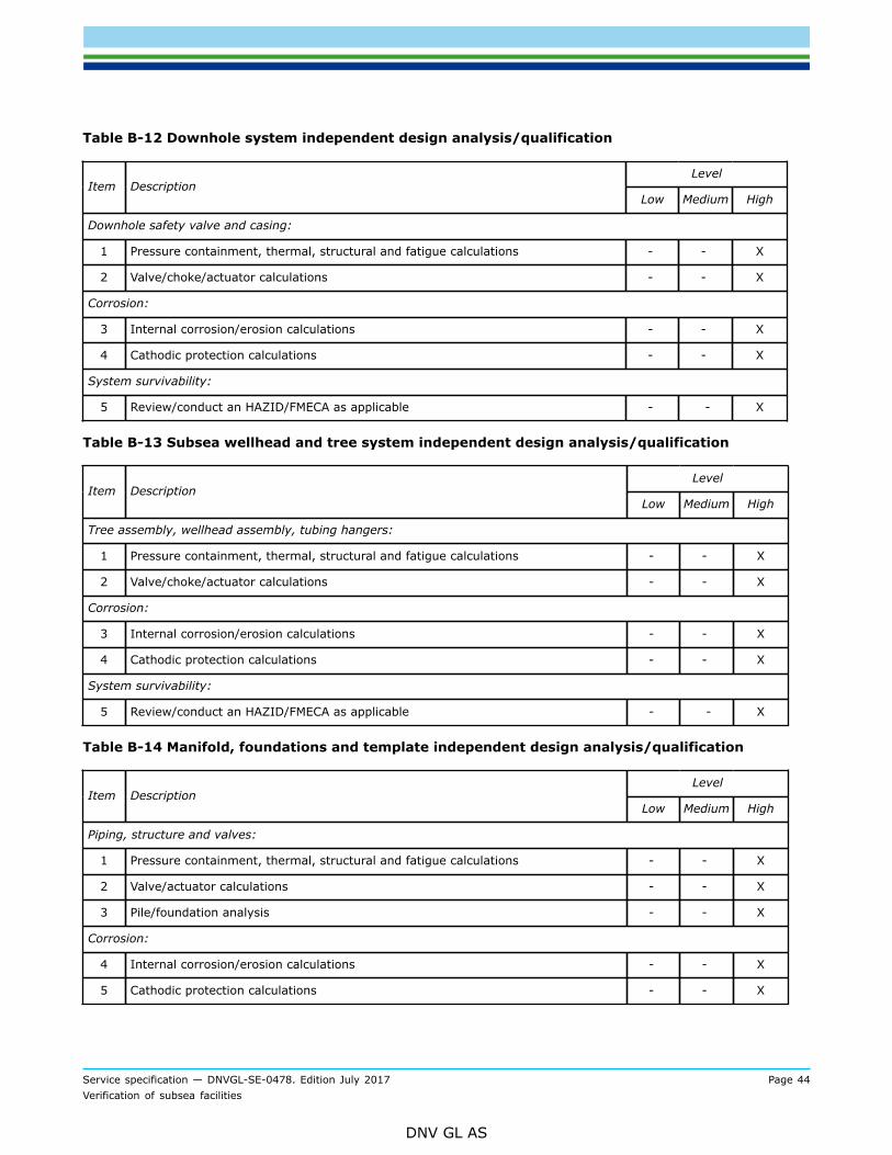
Service specification — DNVGL-SE-0478. Edition July 2017 Page 44Verification of subsea facilities
DNV GL AS
Table B-12 Downhole system independent design analysis/qualification
LevelItem Description
Low Medium High
Downhole safety valve and casing:
1 Pressure containment, thermal, structural and fatigue calculations - - X
2 Valve/choke/actuator calculations - - X
Corrosion:
3 Internal corrosion/erosion calculations - - X
4 Cathodic protection calculations - - X
System survivability:
5 Review/conduct an HAZID/FMECA as applicable - - X
Table B-13 Subsea wellhead and tree system independent design analysis/qualification
LevelItem Description
Low Medium High
Tree assembly, wellhead assembly, tubing hangers:
1 Pressure containment, thermal, structural and fatigue calculations - - X
2 Valve/choke/actuator calculations - - X
Corrosion:
3 Internal corrosion/erosion calculations - - X
4 Cathodic protection calculations - - X
System survivability:
5 Review/conduct an HAZID/FMECA as applicable - - X
Table B-14 Manifold, foundations and template independent design analysis/qualification
LevelItem Description
Low Medium High
Piping, structure and valves:
1 Pressure containment, thermal, structural and fatigue calculations - - X
2 Valve/actuator calculations - - X
3 Pile/foundation analysis - - X
Corrosion:
4 Internal corrosion/erosion calculations - - X
5 Cathodic protection calculations - - X
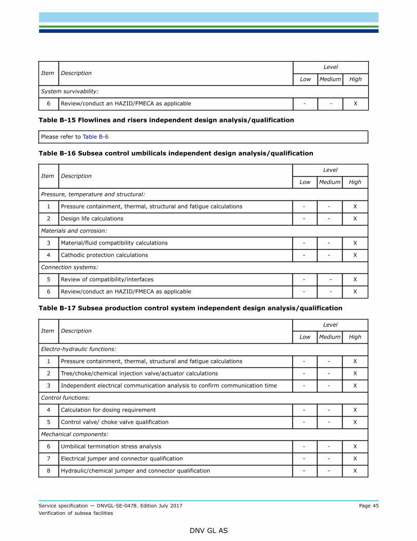
Service specification — DNVGL-SE-0478. Edition July 2017 Page 45Verification of subsea facilities
DNV GL AS
LevelItem Description
Low Medium High
System survivability:
6 Review/conduct an HAZID/FMECA as applicable - - X
Table B-15 Flowlines and risers independent design analysis/qualification
Please refer to Table B-6
Table B-16 Subsea control umbilicals independent design analysis/qualification
LevelItem Description
Low Medium High
Pressure, temperature and structural:
1 Pressure containment, thermal, structural and fatigue calculations - - X
2 Design life calculations - - X
Materials and corrosion:
3 Material/fluid compatibility calculations - - X
4 Cathodic protection calculations - - X
Connection systems:
5 Review of compatibility/interfaces - - X
6 Review/conduct an HAZID/FMECA as applicable - - X
Table B-17 Subsea production control system independent design analysis/qualification
LevelItem Description
Low Medium High
Electro-hydraulic functions:
1 Pressure containment, thermal, structural and fatigue calculations - - X
2 Tree/choke/chemical injection valve/actuator calculations - - X
3 Independent electrical communication analysis to confirm communication time - - X
Control functions:
4 Calculation for dosing requirement - - X
5 Control valve/ choke valve qualification - - X
Mechanical components:
6 Umbilical termination stress analysis - - X
7 Electrical jumper and connector qualification - - X
8 Hydraulic/chemical jumper and connector qualification - - X

Service specification — DNVGL-SE-0478. Edition July 2017 Page 46Verification of subsea facilities
DNV GL AS
LevelItem Description
Low Medium High
9 Stab plate qualification - - X
10 Jumper/umbilical deployment tools qualification - - X
11 Intervention tools qualification - - X
Subsea electronic modules (SEM):
12 Microprocessors and power supply qualification - - X
13 SEM software qualification - - X
14 Instrumentation qualification - - X
Corrosion:
15 Calculation of cathodic protection - - X
System survivability:
16 Review/conduct an HAZID/FMECA as applicable - - X
Table B-18 Subsea processing system independent design analysis/qualification
LevelItem Description
Low Medium High
Separators, rotating equipment and valves:
1 Pressure containment, thermal, structural and fatigue calculations - - X
2 Pump/compressor mechanics/fluid dynamics - - X
3 Valve/actuator calculations - - X
Corrosion:
4 Internal corrosion/erosion calculations - - X
5 Cathodic protection calculations - - X
System survivability:
6 Review/conduct an HAZID/FMECA as applicable - - X
Table B-19 Well intervention/completion/workover system independent design analysis/qualification
LevelItem Description
Low Medium High
Well intervention/completion/workover assembly:
1 Pressure containment, thermal, structural and fatigue calculations - - X
2 Valve/choke/actuator calculations - - X
Mechanical components
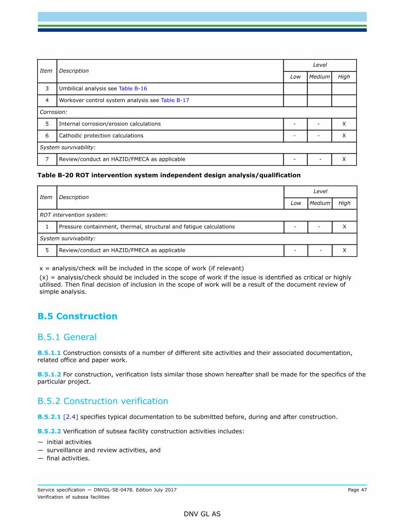
Service specification — DNVGL-SE-0478. Edition July 2017 Page 47Verification of subsea facilities
DNV GL AS
LevelItem Description
Low Medium High
3 Umbilical analysis see Table B-16
4 Workover control system analysis see Table B-17
Corrosion:
5 Internal corrosion/erosion calculations - - X
6 Cathodic protection calculations - - X
System survivability:
7 Review/conduct an HAZID/FMECA as applicable - - X
Table B-20 ROT intervention system independent design analysis/qualification
LevelItem Description
Low Medium High
ROT intervention system:
1 Pressure containment, thermal, structural and fatigue calculations - - X
System survivability:
5 Review/conduct an HAZID/FMECA as applicable - - X
x = analysis/check will be included in the scope of work (if relevant)(x) = analysis/check should be included in the scope of work if the issue is identified as critical or highlyutilised. Then final decision of inclusion in the scope of work will be a result of the document review ofsimple analysis.
B.5 Construction
B.5.1 General
B.5.1.1 Construction consists of a number of different site activities and their associated documentation,related office and paper work.
B.5.1.2 For construction, verification lists similar those shown hereafter shall be made for the specifics of theparticular project.
B.5.2 Construction verification
B.5.2.1 [2.4] specifies typical documentation to be submitted before, during and after construction.
B.5.2.2 Verification of subsea facility construction activities includes:
— initial activities— surveillance and review activities, and— final activities.
Service specification — DNVGL-SE-0478. Edition July 2017 Page 48Verification of subsea facilities
DNV GL AS
B.5.2.3 The initial activities include the review of procedures, attendance during qualification of procedures(e.g. MPQT) and personnel (e.g. welders) and other start-up activities. The surveillance and reviewactivitiesare the site attendance and the final activities are the (continuous) review of production results/records andthe completion of documentation and reports.
B.5.3 Low level construction verification
B.5.3.1 For low level verification, the procedure review consists of a review of the construction managementprocedures and confirmation that the most important aspects of the main specifications have been includedin the procedures. For the qualification of procedures and personnel DNV GL will not attend the actualqualification, but will review the results.
B.5.3.2 During the construction, DNV GL’s verification will be performed during site visits. The verificationwill focus on the critical items/aspects identified in the detailed scope of work tables.
B.5.3.3 The subsequent verification of the final activities will be by spot-checks of the production recordsincluding non-conformance logs, and results from audits, both contractors internal audits or audits performedby other parties.
B.5.4 Medium level construction verification
B.5.4.1 For medium level verification, the procedure review consists of a detailed review of constructionmanagement procedures. Other important procedures will be spot checked to confirm that the mostimportant aspects of the specifications have been included.
B.5.4.2 A quality system audit of relevant installation vessel(s) will be performed.
B.5.4.3 For the qualification of procedures and personnel DNV GL will visit the main qualifications and reviewthe results.
B.5.4.4 During construction, DNV GL’s verification will be performed by full time attendance at the mainsites. The verification will focus on the critical items/aspects as identified in the detailed scope of work tables.
B.5.4.5 Verification of the final activities will be by review of the production records including non-conformance logs, and results from audits, both contractor’s internal audits or audits performed by otherparties, from the main sites and spot checks of the same from other important sites.
B.5.5 High level construction verification
B.5.5.1 For high level verification, the procedure review consists of a detailed review of constructionmanagement procedures. Other procedures will be spot checked to confirmation that important aspects ofthe specifications have been included.
B.5.5.2 A quality system audit of relevant installation vessel(s) will be performed.
B.5.5.3 For qualification of procedures and personnel DNV GL will attend the main qualifications, visit otherqualifications and review the results.
B.5.5.4 During construction, DNV GL’s verification will be performed by full time attendance at the main sitesand by visits to the other important sites. Verification will focus on the critical items/aspects as identified inthe detailed scope of work tables.
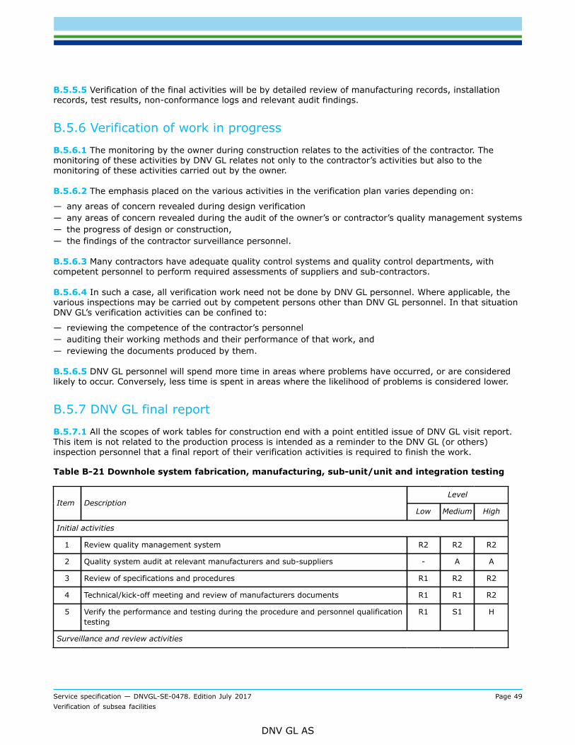
Service specification — DNVGL-SE-0478. Edition July 2017 Page 49Verification of subsea facilities
DNV GL AS
B.5.5.5 Verification of the final activities will be by detailed review of manufacturing records, installationrecords, test results, non-conformance logs and relevant audit findings.
B.5.6 Verification of work in progress
B.5.6.1 The monitoring by the owner during construction relates to the activities of the contractor. Themonitoring of these activities by DNV GL relates not only to the contractor’s activities but also to themonitoring of these activities carried out by the owner.
B.5.6.2 The emphasis placed on the various activities in the verification plan varies depending on:
— any areas of concern revealed during design verification— any areas of concern revealed during the audit of the owner’s or contractor’s quality management systems— the progress of design or construction,— the findings of the contractor surveillance personnel.
B.5.6.3 Many contractors have adequate quality control systems and quality control departments, withcompetent personnel to perform required assessments of suppliers and sub-contractors.
B.5.6.4 In such a case, all verification work need not be done by DNV GL personnel. Where applicable, thevarious inspections may be carried out by competent persons other than DNV GL personnel. In that situationDNV GL’s verification activities can be confined to:
— reviewing the competence of the contractor’s personnel— auditing their working methods and their performance of that work, and— reviewing the documents produced by them.
B.5.6.5 DNV GL personnel will spend more time in areas where problems have occurred, or are consideredlikely to occur. Conversely, less time is spent in areas where the likelihood of problems is considered lower.
B.5.7 DNV GL final report
B.5.7.1 All the scopes of work tables for construction end with a point entitled issue of DNV GL visit report.This item is not related to the production process is intended as a reminder to the DNV GL (or others)inspection personnel that a final report of their verification activities is required to finish the work.
Table B-21 Downhole system fabrication, manufacturing, sub-unit/unit and integration testing
LevelItem Description
Low Medium High
Initial activities
1 Review quality management system R2 R2 R2
2 Quality system audit at relevant manufacturers and sub-suppliers - A A
3 Review of specifications and procedures R1 R2 R2
4 Technical/kick-off meeting and review of manufacturers documents R1 R1 R2
5 Verify the performance and testing during the procedure and personnel qualificationtesting
R1 S1 H
Surveillance and review activities

Service specification — DNVGL-SE-0478. Edition July 2017 Page 50Verification of subsea facilities
DNV GL AS
LevelItem Description
Low Medium High
6 Confirm items manufactured according to specifications:
— review manufacturing records are in accordance with manufacturing quality planand relevant specifications/procedures
— review non-conformance logs
R1 R2 R2
7 Confirm valve functions by:
— witness FAT on all valve functions
S2 S3 S3
9 Confirm cleanliness of hydraulic systems by:
— review of cleanliness report
I R1 R2
10 Confirm pressure integrity of components by:
— review of pressure test certificates for each component
R1 R2 R2
11 Confirm corrosion control by:
— correct application of paint systems— inspection of anode locations in accordance with approved drawings
S1 S2 S3
12 Confirm correct markings by:
— inspection of markings in accordance with approved drawings— correct application of paint systems
S1 S2 S2
13 Confirm correct system function. Monitor factory acceptance tests (FAT) withparticular attention to:
— pressure tests— structural loading tests— valve operation— integration with control system— hydraulic fitness
S1 S3 S3
14 Confirm correct integration with subsea tools and equipment. Monitor systemintegration tests (SIT) with particular attention to:
— systems assembly/fit-up— well intervention tool interfacing— integration with subsea control system
S1 S2 S3
Final activities
15 Confirm downhole system functions by review of:
— FAT records
I R1 R2
16 Confirm integration with subsea tools and equipment by review of:
— SIT reports
I R1 R2
17 Issue DNV GL visit/close-out report H H H
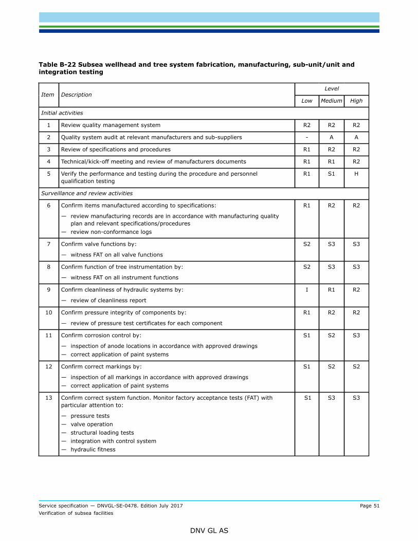
Service specification — DNVGL-SE-0478. Edition July 2017 Page 51Verification of subsea facilities
DNV GL AS
Table B-22 Subsea wellhead and tree system fabrication, manufacturing, sub-unit/unit andintegration testing
LevelItem Description
Low Medium High
Initial activities
1 Review quality management system R2 R2 R2
2 Quality system audit at relevant manufacturers and sub-suppliers - A A
3 Review of specifications and procedures R1 R2 R2
4 Technical/kick-off meeting and review of manufacturers documents R1 R1 R2
5 Verify the performance and testing during the procedure and personnelqualification testing
R1 S1 H
Surveillance and review activities
6 Confirm items manufactured according to specifications:
— review manufacturing records are in accordance with manufacturing qualityplan and relevant specifications/procedures
— review non-conformance logs
R1 R2 R2
7 Confirm valve functions by:
— witness FAT on all valve functions
S2 S3 S3
8 Confirm function of tree instrumentation by:
— witness FAT on all instrument functions
S2 S3 S3
9 Confirm cleanliness of hydraulic systems by:
— review of cleanliness report
I R1 R2
10 Confirm pressure integrity of components by:
— review of pressure test certificates for each component
R1 R2 R2
11 Confirm corrosion control by:
— inspection of anode locations in accordance with approved drawings— correct application of paint systems
S1 S2 S3
12 Confirm correct markings by:
— inspection of all markings in accordance with approved drawings— correct application of paint systems
S1 S2 S2
13 Confirm correct system function. Monitor factory acceptance tests (FAT) withparticular attention to:
— pressure tests— valve operation— structural loading tests— integration with control system— hydraulic fitness
S1 S3 S3
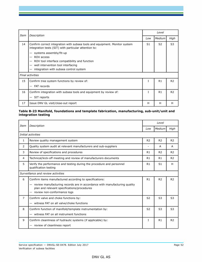
Service specification — DNVGL-SE-0478. Edition July 2017 Page 52Verification of subsea facilities
DNV GL AS
LevelItem Description
Low Medium High
14 Confirm correct integration with subsea tools and equipment. Monitor systemintegration tests (SIT) with particular attention to:
— systems assembly/fit-up— ROV access— ROV tool interface compatibility and function— well intervention tool interfacing— integration with subsea control system
S1 S2 S3
Final activities
15 Confirm tree system functions by review of:
— FAT records
I R1 R2
16 Confirm integration with subsea tools and equipment by review of:
— SIT reports
I R1 R2
17 Issue DNV GL visit/close-out report H H H
Table B-23 Manifold, foundations and template fabrication, manufacturing, sub-unit/unit andintegration testing
LevelItem Description
Low Medium High
Initial activities
1 Review quality management system R2 R2 R2
2 Quality system audit at relevant manufacturers and sub-suppliers - A A
3 Review of specifications and procedures R1 R2 R2
4 Technical/kick-off meeting and review of manufacturers documents R1 R1 R2
5 Verify the performance and testing during the procedure and personnelqualification testing
R1 S1 H
Surveillance and review activities
6 Confirm items manufactured according to specifications:
— review manufacturing records are in accordance with manufacturing qualityplan and relevant specifications/procedures
— review non-conformance logs
R1 R2 R2
7 Confirm valve and choke functions by:
— witness FAT on all valve/choke functions
S2 S3 S3
8 Confirm function of manifold/template instrumentation by:
— witness FAT on all instrument functions
S2 S3 S3
9 Confirm cleanliness of hydraulic systems (if applicable) by:
— review of cleanliness report
I R1 R2
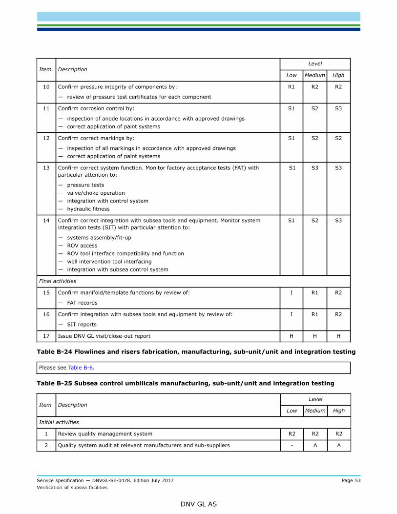
Service specification — DNVGL-SE-0478. Edition July 2017 Page 53Verification of subsea facilities
DNV GL AS
LevelItem Description
Low Medium High
10 Confirm pressure integrity of components by:
— review of pressure test certificates for each component
R1 R2 R2
11 Confirm corrosion control by:
— inspection of anode locations in accordance with approved drawings— correct application of paint systems
S1 S2 S3
12 Confirm correct markings by:
— inspection of all markings in accordance with approved drawings— correct application of paint systems
S1 S2 S2
13 Confirm correct system function. Monitor factory acceptance tests (FAT) withparticular attention to:
— pressure tests— valve/choke operation— integration with control system— hydraulic fitness
S1 S3 S3
14 Confirm correct integration with subsea tools and equipment. Monitor systemintegration tests (SIT) with particular attention to:
— systems assembly/fit-up— ROV access— ROV tool interface compatibility and function— well intervention tool interfacing— integration with subsea control system
S1 S2 S3
Final activities
15 Confirm manifold/template functions by review of:
— FAT records
I R1 R2
16 Confirm integration with subsea tools and equipment by review of:
— SIT reports
I R1 R2
17 Issue DNV GL visit/close-out report H H H
Table B-24 Flowlines and risers fabrication, manufacturing, sub-unit/unit and integration testing
Please see Table B-6.
Table B-25 Subsea control umbilicals manufacturing, sub-unit/unit and integration testing
LevelItem Description
Low Medium High
Initial activities
1 Review quality management system R2 R2 R2
2 Quality system audit at relevant manufacturers and sub-suppliers - A A
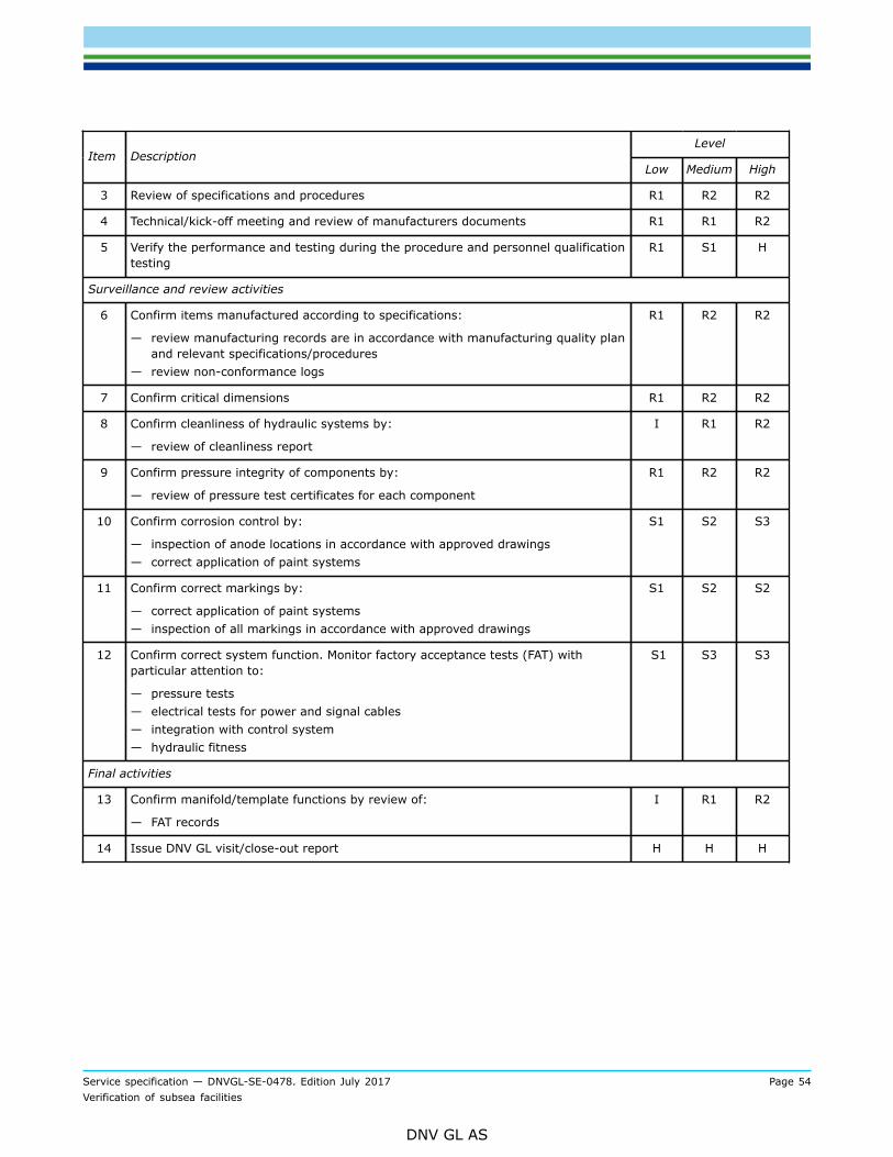
Service specification — DNVGL-SE-0478. Edition July 2017 Page 54Verification of subsea facilities
DNV GL AS
LevelItem Description
Low Medium High
3 Review of specifications and procedures R1 R2 R2
4 Technical/kick-off meeting and review of manufacturers documents R1 R1 R2
5 Verify the performance and testing during the procedure and personnel qualificationtesting
R1 S1 H
Surveillance and review activities
6 Confirm items manufactured according to specifications:
— review manufacturing records are in accordance with manufacturing quality planand relevant specifications/procedures
— review non-conformance logs
R1 R2 R2
7 Confirm critical dimensions R1 R2 R2
8 Confirm cleanliness of hydraulic systems by:
— review of cleanliness report
I R1 R2
9 Confirm pressure integrity of components by:
— review of pressure test certificates for each component
R1 R2 R2
10 Confirm corrosion control by:
— inspection of anode locations in accordance with approved drawings— correct application of paint systems
S1 S2 S3
11 Confirm correct markings by:
— correct application of paint systems— inspection of all markings in accordance with approved drawings
S1 S2 S2
12 Confirm correct system function. Monitor factory acceptance tests (FAT) withparticular attention to:
— pressure tests— electrical tests for power and signal cables— integration with control system— hydraulic fitness
S1 S3 S3
Final activities
13 Confirm manifold/template functions by review of:
— FAT records
I R1 R2
14 Issue DNV GL visit/close-out report H H H
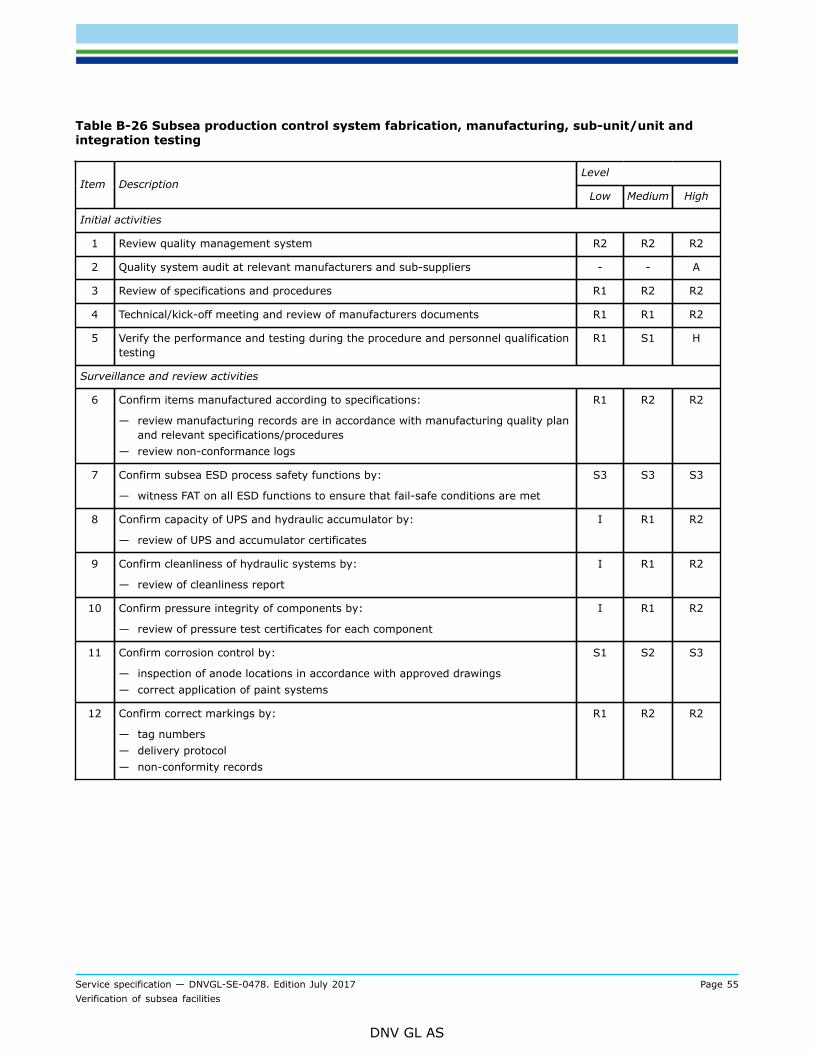
Service specification — DNVGL-SE-0478. Edition July 2017 Page 55Verification of subsea facilities
DNV GL AS
Table B-26 Subsea production control system fabrication, manufacturing, sub-unit/unit andintegration testing
LevelItem Description
Low Medium High
Initial activities
1 Review quality management system R2 R2 R2
2 Quality system audit at relevant manufacturers and sub-suppliers - - A
3 Review of specifications and procedures R1 R2 R2
4 Technical/kick-off meeting and review of manufacturers documents R1 R1 R2
5 Verify the performance and testing during the procedure and personnel qualificationtesting
R1 S1 H
Surveillance and review activities
6 Confirm items manufactured according to specifications:
— review manufacturing records are in accordance with manufacturing quality planand relevant specifications/procedures
— review non-conformance logs
R1 R2 R2
7 Confirm subsea ESD process safety functions by:
— witness FAT on all ESD functions to ensure that fail-safe conditions are met
S3 S3 S3
8 Confirm capacity of UPS and hydraulic accumulator by:
— review of UPS and accumulator certificates
I R1 R2
9 Confirm cleanliness of hydraulic systems by:
— review of cleanliness report
I R1 R2
10 Confirm pressure integrity of components by:
— review of pressure test certificates for each component
I R1 R2
11 Confirm corrosion control by:
— inspection of anode locations in accordance with approved drawings— correct application of paint systems
S1 S2 S3
12 Confirm correct markings by:
— tag numbers— delivery protocol— non-conformity records
R1 R2 R2
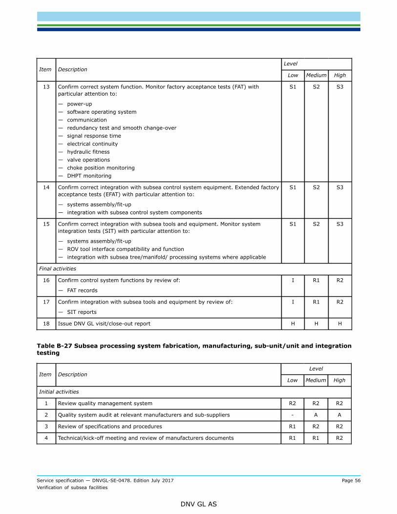
Service specification — DNVGL-SE-0478. Edition July 2017 Page 56Verification of subsea facilities
DNV GL AS
LevelItem Description
Low Medium High
13 Confirm correct system function. Monitor factory acceptance tests (FAT) withparticular attention to:
— power-up— software operating system— communication— redundancy test and smooth change-over— signal response time— electrical continuity— hydraulic fitness— valve operations— choke position monitoring— DHPT monitoring
S1 S2 S3
14 Confirm correct integration with subsea control system equipment. Extended factoryacceptance tests (EFAT) with particular attention to:
— systems assembly/fit-up— integration with subsea control system components
S1 S2 S3
15 Confirm correct integration with subsea tools and equipment. Monitor systemintegration tests (SIT) with particular attention to:
— systems assembly/fit-up— ROV tool interface compatibility and function— integration with subsea tree/manifold/ processing systems where applicable
S1 S2 S3
Final activities
16 Confirm control system functions by review of:
— FAT records
I R1 R2
17 Confirm integration with subsea tools and equipment by review of:
— SIT reports
I R1 R2
18 Issue DNV GL visit/close-out report H H H
Table B-27 Subsea processing system fabrication, manufacturing, sub-unit/unit and integrationtesting
LevelItem Description
Low Medium High
Initial activities
1 Review quality management system R2 R2 R2
2 Quality system audit at relevant manufacturers and sub-suppliers - A A
3 Review of specifications and procedures R1 R2 R2
4 Technical/kick-off meeting and review of manufacturers documents R1 R1 R2
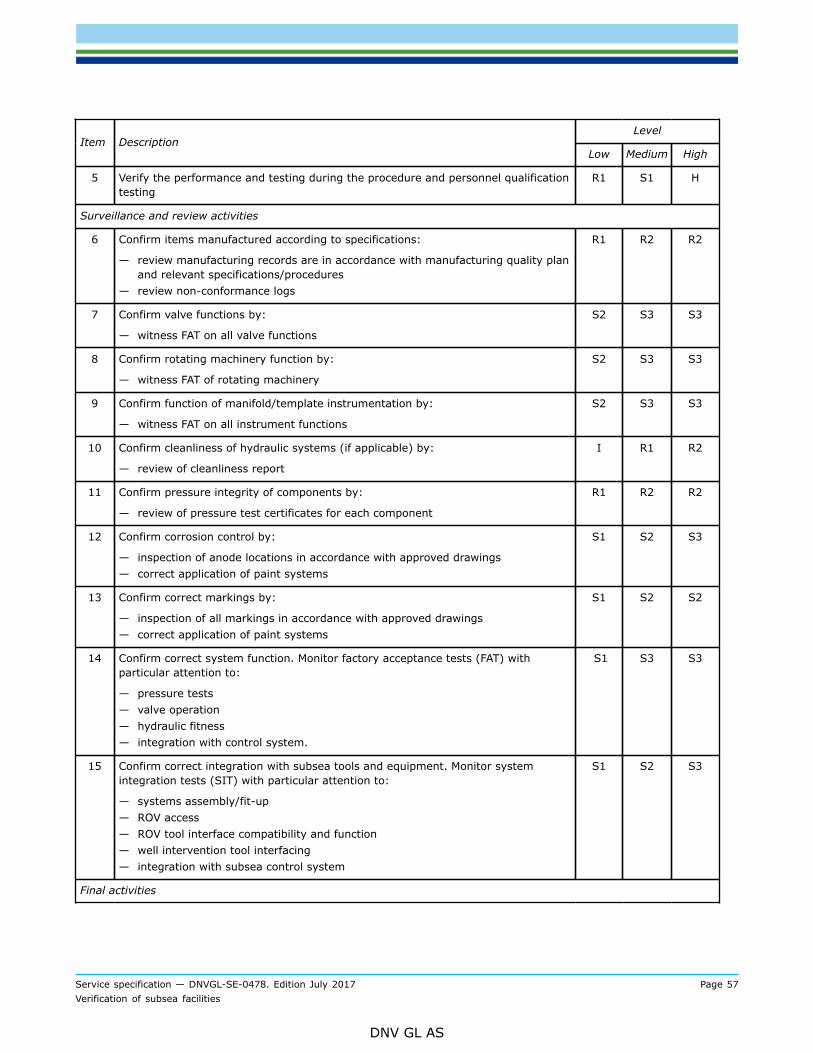
Service specification — DNVGL-SE-0478. Edition July 2017 Page 57Verification of subsea facilities
DNV GL AS
LevelItem Description
Low Medium High
5 Verify the performance and testing during the procedure and personnel qualificationtesting
R1 S1 H
Surveillance and review activities
6 Confirm items manufactured according to specifications:
— review manufacturing records are in accordance with manufacturing quality planand relevant specifications/procedures
— review non-conformance logs
R1 R2 R2
7 Confirm valve functions by:
— witness FAT on all valve functions
S2 S3 S3
8 Confirm rotating machinery function by:
— witness FAT of rotating machinery
S2 S3 S3
9 Confirm function of manifold/template instrumentation by:
— witness FAT on all instrument functions
S2 S3 S3
10 Confirm cleanliness of hydraulic systems (if applicable) by:
— review of cleanliness report
I R1 R2
11 Confirm pressure integrity of components by:
— review of pressure test certificates for each component
R1 R2 R2
12 Confirm corrosion control by:
— inspection of anode locations in accordance with approved drawings— correct application of paint systems
S1 S2 S3
13 Confirm correct markings by:
— inspection of all markings in accordance with approved drawings— correct application of paint systems
S1 S2 S2
14 Confirm correct system function. Monitor factory acceptance tests (FAT) withparticular attention to:
— pressure tests— valve operation— hydraulic fitness— integration with control system.
S1 S3 S3
15 Confirm correct integration with subsea tools and equipment. Monitor systemintegration tests (SIT) with particular attention to:
— systems assembly/fit-up— ROV access— ROV tool interface compatibility and function— well intervention tool interfacing— integration with subsea control system
S1 S2 S3
Final activities

Service specification — DNVGL-SE-0478. Edition July 2017 Page 58Verification of subsea facilities
DNV GL AS
LevelItem Description
Low Medium High
16 Confirm process system functions by review of:
— FAT records
I R1 R2
17 Confirm integration with subsea tools and equipment by review of:
— SIT reports
I R1 R2
18 Issue DNV GL visit/close-out report H H H
Table B-28 Well intervention/completion/workover system fabrication, manufacturing, sub-unit/unit and integration testing
LevelItem Description
Low Medium High
Initial activities
1 Review quality management system R2 R2 R2
2 Quality system audit at relevant manufacturers and sub-suppliers - A A
3 Review of specifications and procedures R1 R2 R2
4 Technical/kick-off meeting and review of manufacturers documents R1 R1 R2
5 Verify the performance and testing during the procedure and personnel qualificationtesting
R1 S1 H
Surveillance and review activities
6 Confirm items manufactured according to specifications:
— review manufacturing records are in accordance with manufacturing quality planand relevant specifications/procedures
— review non-conformance logs
R1 R2 R2
7 Confirm valve functions by:
— witness FAT on all valve functions
S2 S3 S3
8 Confirm function of intervention instrumentation by:
— witness FAT on all instrument functions
S2 S3 S3
9 Confirm cleanliness of hydraulic systems by:
— review of cleanliness report
I R1 R2
10 Confirm pressure integrity of components by:
— review of pressure test certificates for each component
R1 R2 R2
11 Confirm corrosion control by:
— inspection of anode locations in accordance with approved drawings— correct application of paint systems
S1 S2 S3
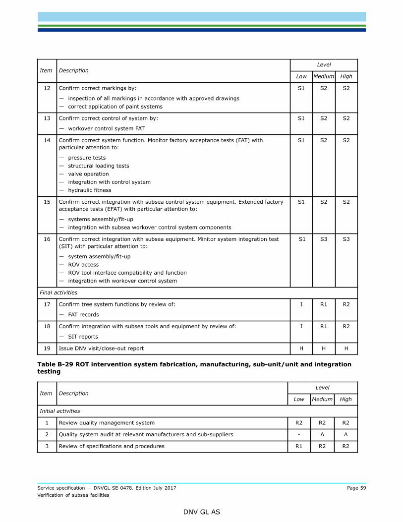
Service specification — DNVGL-SE-0478. Edition July 2017 Page 59Verification of subsea facilities
DNV GL AS
LevelItem Description
Low Medium High
12 Confirm correct markings by:
— inspection of all markings in accordance with approved drawings— correct application of paint systems
S1 S2 S2
13 Confirm correct control of system by:
— workover control system FAT
S1 S2 S2
14 Confirm correct system function. Monitor factory acceptance tests (FAT) withparticular attention to:
— pressure tests— structural loading tests— valve operation— integration with control system— hydraulic fitness
S1 S2 S2
15 Confirm correct integration with subsea control system equipment. Extended factoryacceptance tests (EFAT) with particular attention to:
— systems assembly/fit-up— integration with subsea workover control system components
S1 S2 S2
16 Confirm correct integration with subsea equipment. Minitor system integration test(SIT) with particular attention to:
— system assembly/fit-up— ROV access— ROV tool interface compatibility and function— integration with workover control system
S1 S3 S3
Final activities
17 Confirm tree system functions by review of:
— FAT records
I R1 R2
18 Confirm integration with subsea tools and equipment by review of:
— SIT reports
I R1 R2
19 Issue DNV visit/close-out report H H H
Table B-29 ROT intervention system fabrication, manufacturing, sub-unit/unit and integrationtesting
LevelItem Description
Low Medium High
Initial activities
1 Review quality management system R2 R2 R2
2 Quality system audit at relevant manufacturers and sub-suppliers - A A
3 Review of specifications and procedures R1 R2 R2
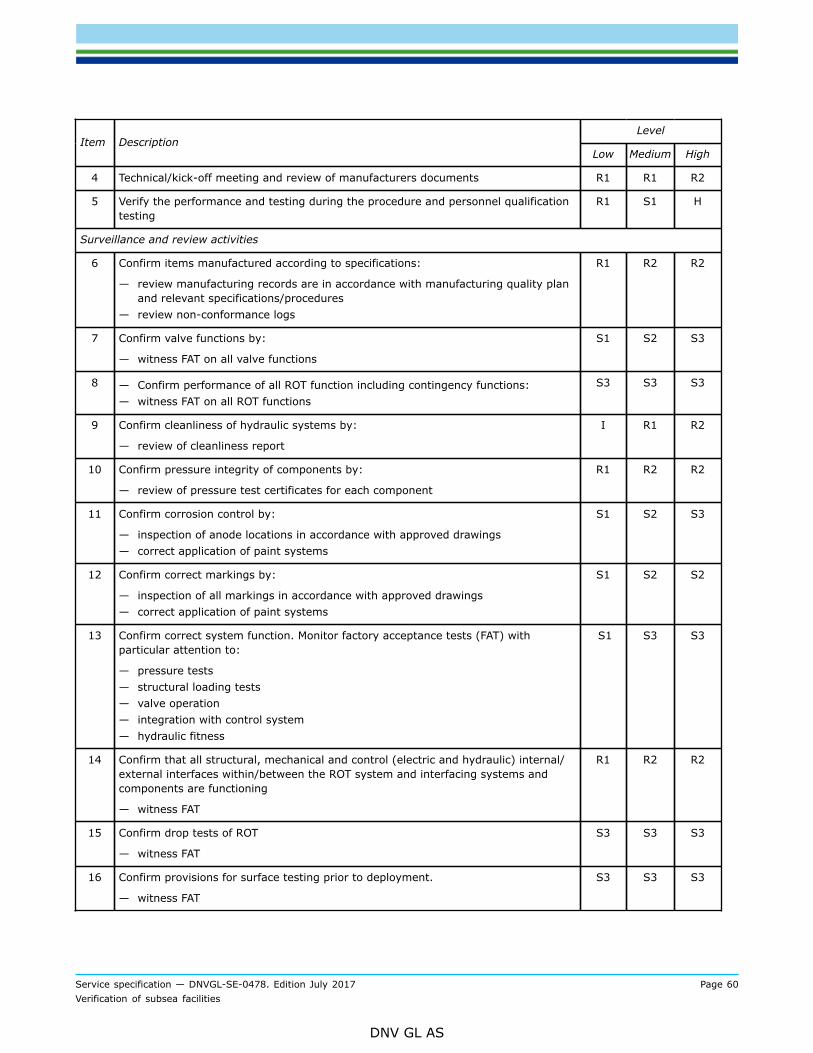
Service specification — DNVGL-SE-0478. Edition July 2017 Page 60Verification of subsea facilities
DNV GL AS
LevelItem Description
Low Medium High
4 Technical/kick-off meeting and review of manufacturers documents R1 R1 R2
5 Verify the performance and testing during the procedure and personnel qualificationtesting
R1 S1 H
Surveillance and review activities
6 Confirm items manufactured according to specifications:
— review manufacturing records are in accordance with manufacturing quality planand relevant specifications/procedures
— review non-conformance logs
R1 R2 R2
7 Confirm valve functions by:
— witness FAT on all valve functions
S1 S2 S3
8 — Confirm performance of all ROT function including contingency functions:— witness FAT on all ROT functions
S3 S3 S3
9 Confirm cleanliness of hydraulic systems by:
— review of cleanliness report
I R1 R2
10 Confirm pressure integrity of components by:
— review of pressure test certificates for each component
R1 R2 R2
11 Confirm corrosion control by:
— inspection of anode locations in accordance with approved drawings— correct application of paint systems
S1 S2 S3
12 Confirm correct markings by:
— inspection of all markings in accordance with approved drawings— correct application of paint systems
S1 S2 S2
13 Confirm correct system function. Monitor factory acceptance tests (FAT) withparticular attention to:
— pressure tests— structural loading tests— valve operation— integration with control system— hydraulic fitness
S1 S3 S3
14 Confirm that all structural, mechanical and control (electric and hydraulic) internal/external interfaces within/between the ROT system and interfacing systems andcomponents are functioning
— witness FAT
R1 R2 R2
15 Confirm drop tests of ROT
— witness FAT
S3 S3 S3
16 Confirm provisions for surface testing prior to deployment.
— witness FAT
S3 S3 S3
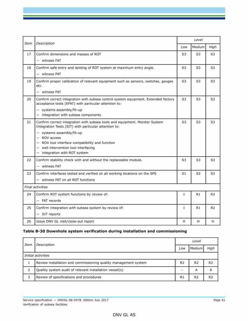
Service specification — DNVGL-SE-0478. Edition July 2017 Page 61Verification of subsea facilities
DNV GL AS
LevelItem Description
Low Medium High
17 Confirm dimensions and masses of ROT
— witness FAT
S3 S3 S3
18 Confirm safe entry and landing of ROT system at maximum entry angle.
— witness FAT
S3 S3 S3
19 Confirm proper calibration of relevant equipment such as sensors, switches, gaugesetc.
— witness FAT
S3 S3 S3
20 Confirm correct integration with subsea control system equipment. Extended factoryacceptance tests (EFAT) with particular attention to:
— systems assembly/fit-up— integration with subsea components
S3 S3 S3
21 Confirm correct integration with subsea tools and equipment. Monitor SystemIntegration Tests (SIT) with particular attention to:
— systems assembly/fit-up— ROV access— ROV tool interface compatibility and function— well intervention tool interfacing— integration with ROT system
S3 S3 S3
22 Confirm stability check with and without the replaceable module.
— witness FAT
S3 S3 S3
23 Confirm interfaces tested and verified on all working locations on the SPS
— witness FAT on all ROT functions
S1 S2 S3
Final activities
24 Confirm ROT system functions by review of:
— FAT records
I R1 R2
25 Confirm integration with subsea system by review of:
— SIT reports
I R1 R2
26 Issue DNV GL visit/close-out report H H H
Table B-30 Downhole system verification during installation and commissioning
LevelItem Description
Low Medium High
Initial activities
1 Review installation and commissioning quality management system R2 R2 R2
2 Quality system audit of relevant installation vessel(s) - A A
3 Review of specifications and procedures R1 R2 R2

Service specification — DNVGL-SE-0478. Edition July 2017 Page 62Verification of subsea facilities
DNV GL AS
LevelItem Description
Low Medium High
4 Technical/kick-off meeting and review of installer’s documents R1 R1 R2
5 Verify the performance and testing during the procedure and personnel qualificationtesting
R1 S1 H
Surveillance and review activities
6 Review installation records, including non-conformance logs, to confirm correctequipment hook-up.
R1 R2 R2
7 Review pressure test records R1 R2 R2
8 Monitor installation to confirm correct equipment hook-up - - S3
9 Confirm by review of commissioning records that all actuated valves fail to a safeposition as per the P&IDs
R1 R1 R2
10 Witness operation of tree and choke valves - S3 S3
11 Witness testing to confirm that all actuated valves fail to a safe position as per theP&IDs
- S3 S3
Final activities
12 Issue DNV GL visit/close-out report H H H
Table B-31 Subsea tree and choke system verification during installation and commissioning
LevelItem Description
Low Medium High
Initial activities
1 Review installation and commissioning quality management system R2 R2 R2
2 Quality system audit of relevant installation vessel(s) - A A
3 Review of specifications and procedures R1 R2 R2
4 Technical/kick-off meeting and review of installer’s documents R1 R1 R2
5 Verify the performance and testing during the procedure and personnel qualificationtesting
R1 S1 H
Surveillance and review activities
6 Review installation records, including non-conformance logs, to confirm correctequipment hook-up.
R1 R2 R2
7 Review pressure test records R1 R2 R2
8 Monitor installation to confirm correct equipment hook-up - - S3
9 Confirm by review of commissioning records that all actuated valves fail to a safeposition as per the P&IDs
R1 R1 R2
10 Witness operation of tree and choke valves - S3 S3

Service specification — DNVGL-SE-0478. Edition July 2017 Page 63Verification of subsea facilities
DNV GL AS
LevelItem Description
Low Medium High
11 Witness testing to confirm that all actuated valves fail to a safe position as per theP&IDs
- S3 S3
Final activities
12 Issue DNV GL visit/close-out report H H H
Table B-32 Manifold, foundations and template verification during installation and commissioning
LevelItem Description
Low Medium High
Initial activities
1 Review installation and commissioning quality management system R2 R2 R2
2 Quality system audit of relevant installation vessel(s) - A A
3 Review of specifications and procedures R1 R2 R2
4 Technical/kick-off meeting and review of installer’s documents R1 R1 R2
5 Verify the performance and testing during the procedure and personnel qualificationtesting
R1 S1 H
Surveillance and review activities
6 Review installation records, including non-conformance logs, to confirm correctequipment hook-up.
R1 R2 R2
7 Review pressure test records R1 R2 R2
8 Monitor installation to confirm correct equipment hook-up - - S3
9 Confirm by review of commissioning records that all actuated valves fail to a safeposition as per the P&IDs
R1 R1 R2
10 Witness operation of all remotely operated valves - S3 S3
11 Witness testing to confirm that all actuated valves fail to a safe position as per theP&IDs
- S3 S3
Final activities
12 Issue DNV GL visit/close-out report H H H
Table B-33 Flowlines and risers verification during installation and commissioning
Please see Table B-6
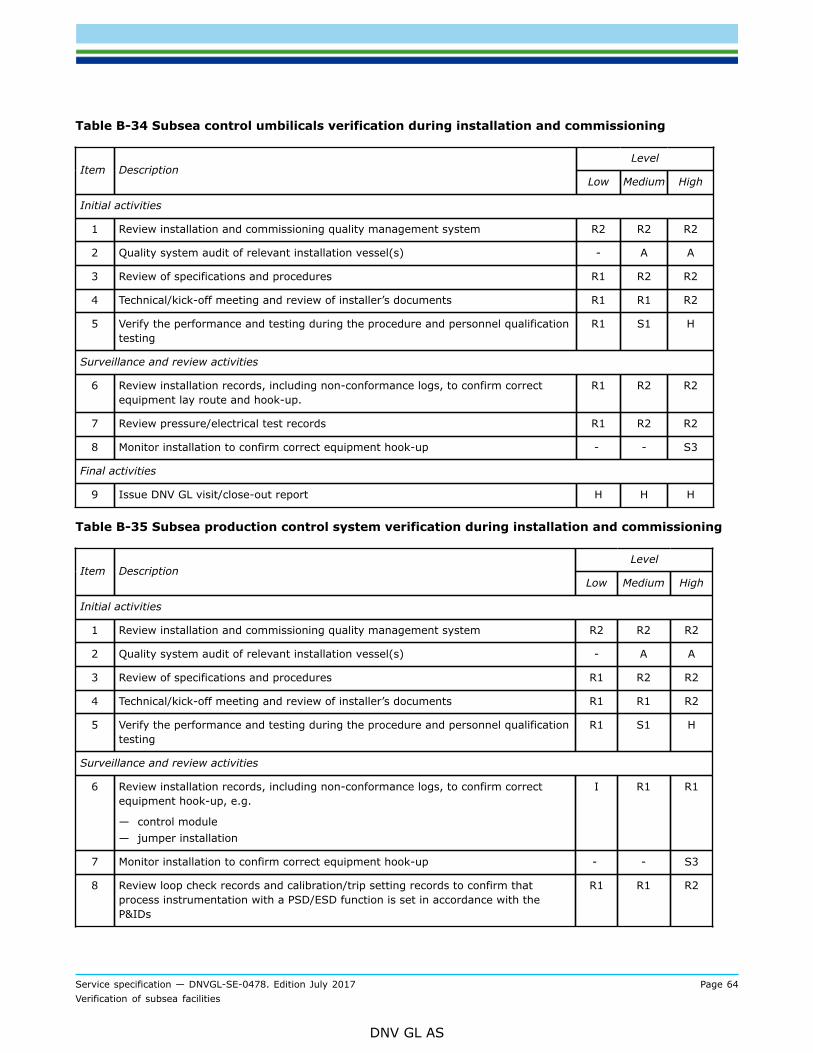
Service specification — DNVGL-SE-0478. Edition July 2017 Page 64Verification of subsea facilities
DNV GL AS
Table B-34 Subsea control umbilicals verification during installation and commissioning
LevelItem Description
Low Medium High
Initial activities
1 Review installation and commissioning quality management system R2 R2 R2
2 Quality system audit of relevant installation vessel(s) - A A
3 Review of specifications and procedures R1 R2 R2
4 Technical/kick-off meeting and review of installer’s documents R1 R1 R2
5 Verify the performance and testing during the procedure and personnel qualificationtesting
R1 S1 H
Surveillance and review activities
6 Review installation records, including non-conformance logs, to confirm correctequipment lay route and hook-up.
R1 R2 R2
7 Review pressure/electrical test records R1 R2 R2
8 Monitor installation to confirm correct equipment hook-up - - S3
Final activities
9 Issue DNV GL visit/close-out report H H H
Table B-35 Subsea production control system verification during installation and commissioning
LevelItem Description
Low Medium High
Initial activities
1 Review installation and commissioning quality management system R2 R2 R2
2 Quality system audit of relevant installation vessel(s) - A A
3 Review of specifications and procedures R1 R2 R2
4 Technical/kick-off meeting and review of installer’s documents R1 R1 R2
5 Verify the performance and testing during the procedure and personnel qualificationtesting
R1 S1 H
Surveillance and review activities
6 Review installation records, including non-conformance logs, to confirm correctequipment hook-up, e.g.
— control module— jumper installation
I R1 R1
7 Monitor installation to confirm correct equipment hook-up - - S3
8 Review loop check records and calibration/trip setting records to confirm thatprocess instrumentation with a PSD/ESD function is set in accordance with theP&IDs
R1 R1 R2
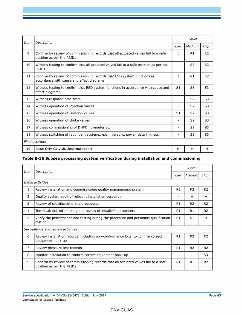
Service specification — DNVGL-SE-0478. Edition July 2017 Page 65Verification of subsea facilities
DNV GL AS
LevelItem Description
Low Medium High
9 Confirm by review of commissioning records that all actuated valves fail to a safeposition as per the P&IDs
I R1 R2
10 Witness testing to confirm that all actuated valves fail to a safe position as per theP&IDs
- S3 S3
11 Confirm by review of commissioning records that ESD system functions inaccordance with cause and effect diagrams
I R1 R2
12 Witness testing to confirm that ESD system functions in accordance with cause andeffect diagrams
S1 S3 S3
13 Witness response time tests - S2 S3
14 Witness operation of injection valves - S2 S3
15 Witness operation of isolation valves S1 S2 S3
16 Witness operation of choke valves - S2 S3
17 Witness commissioning of DHPT, flowmeter etc. - S2 S3
18 Witness switching of redundant systems, e.g. hydraulic, power, data link, etc. - S2 S3
Final activities
19 Issue DNV GL visit/close-out report H H H
Table B-36 Subsea processing system verification during installation and commissioning
LevelItem Description
Low Medium High
Initial activities
1 Review installation and commissioning quality management system R2 R2 R2
2 Quality system audit of relevant installation vessel(s) - A A
3 Review of specifications and procedures R1 R2 R2
4 Technical/kick-off meeting and review of installer’s documents R1 R1 R2
5 Verify the performance and testing during the procedure and personnel qualificationtesting
R1 S1 H
Surveillance and review activities
6 Review installation records, including non-conformance logs, to confirm correctequipment hook-up
R1 R2 R2
7 Review pressure test records R1 R2 R2
8 Monitor installation to confirm correct equipment hook-up - - S3
9 Confirm by review of commissioning records that all actuated valves fail to a safeposition as per the P&IDs
R1 R1 R2
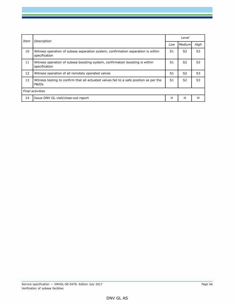
Service specification — DNVGL-SE-0478. Edition July 2017 Page 66Verification of subsea facilities
DNV GL AS
LevelItem Description
Low Medium High
10 Witness operation of subsea separation system, confirmation separation is withinspecification
S1 S2 S3
11 Witness operation of subsea boosting system, confirmation boosting is withinspecification
S1 S2 S3
12 Witness operation of all remotely operated valves S1 S2 S3
13 Witness testing to confirm that all actuated valves fail to a safe position as per theP&IDs
S1 S2 S3
Final activities
14 Issue DNV GL visit/close-out report H H H

Service specification — DNVGL-SE-0478. Edition July 2017 Page 67Verification of subsea facilities
DNV GL AS
APPENDIX C EXAMPLES OF VERIFICATION DOCUMENTS
C.1 Verification documents
C.1.1 Validity of verification documents
C.1.1.1 Verification documents are, in principle, documents confirming that an examination has been carriedout, and are valid only at the time of issue.
C.1.2 Statement of conformity
C.1.2.1 A statement of conformity can be issued on completion of each particular project phase, or naturalpart thereof, and shall be based on a dedicated verification report.
C.1.2.2 A statement of conformity shall be issued as a formal statement confirming that verification ofdocuments and/or activities, has found that the subsea facility, a part thereof, or a verification activity,complies with the requirements applicable for that particular project phase.
C.1.2.3 The technical information on a statement of conformity shall contain:
— subsea facility description and item number, if relevant— application (operational limitations and conditions of use) for which the subsea facility is intended— codes and standards with which the subsea facilities have been found to comply— level of verification— an appendix containing the accompanying dedicated verification report.
C.1.2.4 A statement of conformity shall be signed by the DNV GL project manager.An example of a typical statement of conformity is shown at the end of the document.
C.1.3 Verification reports
C.1.3.1 Verification reports are issued to confirm that the relevant product or service has been completed inaccordance with specified requirements.
C.1.3.2 The report shall include information such as:
— product or service description and item number, if relevant— application (operational limitations and conditions of use) for which the product or service is intended— codes and standards with which the product or service has been verified against— clear statement of the conclusion from the verification (does it or does it not meet the specified
requirements)— codes and standards used as reference— documentation on which the verification report is based (documents, drawings, correspondence, including
revision numbers)— project-specific scope of work tables— any comments— identification of any non-conformances.
C.1.3.3 The verification report shall always be dated and have two signatures, the originator and the DNV GLinternal verifier.
Service specification — DNVGL-SE-0478. Edition July 2017 Page 68Verification of subsea facilities
DNV GL AS
C.1.4 Verification comments
C.1.4.1 Reviews of documents shall be reported using verification comment sheets (often called VerComs).These documents give details to the client of aspects of subsea facilities design and construction that DNVGL:
— considers do not meet the specified requirements— does not have enough information to make a decision— offers advice based on its own experience.
C.1.4.2 Only in the first two instances does DNV GL expect a response from the owner or its contractors.
C.1.4.3 An example of a typical verification comment sheet is shown at the end of the document.
C.1.5 Audit report
C.1.5.1 Audit reports are issued to confirm that a company’s quality management system has been reviewedto confirm compliance (or not) with the nominated standard and project requirements. In addition, the auditreports confirm compliance with the documented procedures and that these procedures are effective.
C.1.5.2 Audit reports shall contain information such as whether:
— the company has a documented quality system— this quality system been certified by an accredited certification body for the product (or service) in
question— the quality system covers the following quality assurance elements adequately for the product:
— organisation— authority/responsibility— job descriptions for key persons— internal quality audits— documentation change control— job instructions/procedures— non-conformance/corrective action
— there are adequate procedures for activities such as:
— calibration of equipment— material identification and marking— control of special processes such as welding, NDT, PWHT— non-conformance identification and handling— inspection status— final inspection
— the company’s facilities are, in general, considered adequate for the scope of supply
— a quality plan been prepared for the order concerned
— the purchaser or their appointed inspection agency are planned to attend the works
— there are any problem areas identified.
C.1.5.3 An example of a typical audit report is shown at the end of the document.
Service specification — DNVGL-SE-0478. Edition July 2017 Page 69Verification of subsea facilities
DNV GL AS
C.1.6 Visit reports
C.1.6.1 Visit reports are documentation/recording of attendance activity by DNV GL.Guidance note:Visit reports are and may be called by different names. Examples are inspection release note, survey report, inspection certificate,site report, etc.
---e-n-d---o-f---g-u-i-d-a-n-c-e---n-o-t-e---
C.1.6.2 A visit report shall contain enough information to identify clearly the product or service that hasbeen examined, the operating conditions or specifications to which it has been examined and the conclusionreached by DNV GL.
C.1.6.3 The visit report shall be printed on the relevant form and shall contain as much information aspossible in accordance with the standard headings in the form. In addition, the report number shall beshown.
C.1.6.4 An example of a typical visit report is shown at the end of the document.
C.2 Use of quality management systems
C.2.1 General
C.2.1.1 The assurance of subsea facility integrity and function requires that gross errors during design,construction and operation be minimised. The likelihood of gross errors shall be reduced in a systematicmanner by the operation of a quality management system adequate for the work being carried out.
C.2.1.2 Quality management systems frequently are documented at three levels:
— the quality manual and related procedures document how the organisation, as a whole, manages thequality of all its products and services
— the quality plan documents the specific procedures related to a particular project— the inspection and test plan documents how the quality control activities for a particular project shall be
carried out and recorded.
C.2.2 Quality plans
C.2.2.1 The basic function of a quality plan is as a memory aid in the management of a project. In anorganisation with many quality procedures for a variety of functions the quality plan states those thatare applicable to that particular project. The quality plan acts as a route map through the complexities ofmanagement of the project and highlights those activities relevant to quality management.
C.2.2.2 The project quality plan normally consists of two parts; firstly, a narrative description of the meansof controlling the project, and secondly, a tabular description of the inspections and tests to be carried outduring the work.
C.2.2.3 The quality plan should address:
— organisational details of the project— authorities and responsibilities of key personnel— interfaces between, the client, contractors, sub-contractors and third parties— quality assurance activities placed on sub-contractors
Service specification — DNVGL-SE-0478. Edition July 2017 Page 70Verification of subsea facilities
DNV GL AS
— cross references to existing company procedures.
C.2.2.4 The narrative part of the quality plan should include a description of:
— the applicable standards— project organisation and responsibilities— review of the contractual requirements— project planning and progress reporting— procedures for such activities as design control, purchasing, construction, installation, commissioning,
interface control and auditing— procedures for inspection and maintenance as well as normal operation— emergency response issues.
C.2.2.5 Additionally, the narrative part of the plan should describe the documentation requirements. Itshould be specified:
— what documents are required— at what stage these documents are required— who is responsible for preparing the documents— relevant parties to whom documents are submitted— how any necessary approvals are acquired— who has originals and who has copies,— if copies have to be certified copies— the length of time documents are to be retained and by whom.
C.2.3 Inspection and test plans
C.2.3.1 The tabular description of the inspections and tests to be carried out during the work is frequentlyknown as the inspection and test plan.
C.2.3.2 The following items should be checked for inclusion within the inspection and test plan:
— each inspection and test point and its relative location in the production cycle should be shown,— the characteristics to be inspected and tested at each point should be identified— the use of sub-contractors should be indicated and details of how the verification of sub-contractor’s
quality shall be carried out should be shown— hold points established by the constructor, the operator or a third party, where witness or review of the
selected inspection or test is required, should be shown.
C.2.4 Review of quality management programme
C.2.4.1 The contractor’s quality manual shall be reviewed for compliance with ISO 9001 or 9002 asappropriate. The contractor’s operations should be audited to establish compliance with the documentedsystem.
C.2.4.2 If the contractor has a quality system certified by an accredited third party certification body,this may be taken as evidence of a satisfactory quality system provided the certificate is relevant to thecontractor’s scope of work for the project. However, the last two years’ periodical audit reports shall bereviewed to identify if any recurring non-conformities have been revealed.
C.2.4.3 Any weaknesses revealed during this audit, or review of periodical audit reports, shall be consideredwhen planning the contractor monitoring activities.
Service specification — DNVGL-SE-0478. Edition July 2017 Page 71Verification of subsea facilities
DNV GL AS
C.2.4.4 Surveillance of the continuing acceptability of the contractor’s quality management system is carriedout by observing a selection of audits carried out by the contractor as part of its internal audit system. Theaudits to be observed should be selected over the length of the project at suitable intervals and should coveras wide a selection of activities as possible.
C.2.4.5 Contractors’ inspection and test plans for the various activities undertaken during their scope of workfor the pipeline shall be reviewed and accepted, if adequate.
C.3 Document forms
C.3.1 Introduction
C.3.1.1 The end of this appendix includes example forms for use by DNV GL in verification.
C.3.1.2 The following forms are included:
— statement of conformity— verification comments sheet— audit report— visit report.

Service specification — DNVGL-SE-0478. Edition July 2017 Page 72Verification of subsea facilities
DNV GL AS
C.3.2 Statement of conformity
EXAMPLE
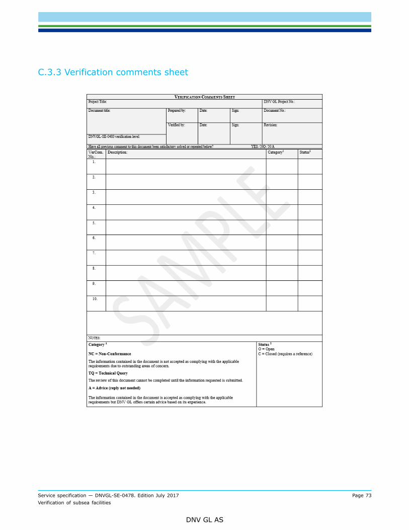
Service specification — DNVGL-SE-0478. Edition July 2017 Page 73Verification of subsea facilities
DNV GL AS
C.3.3 Verification comments sheet
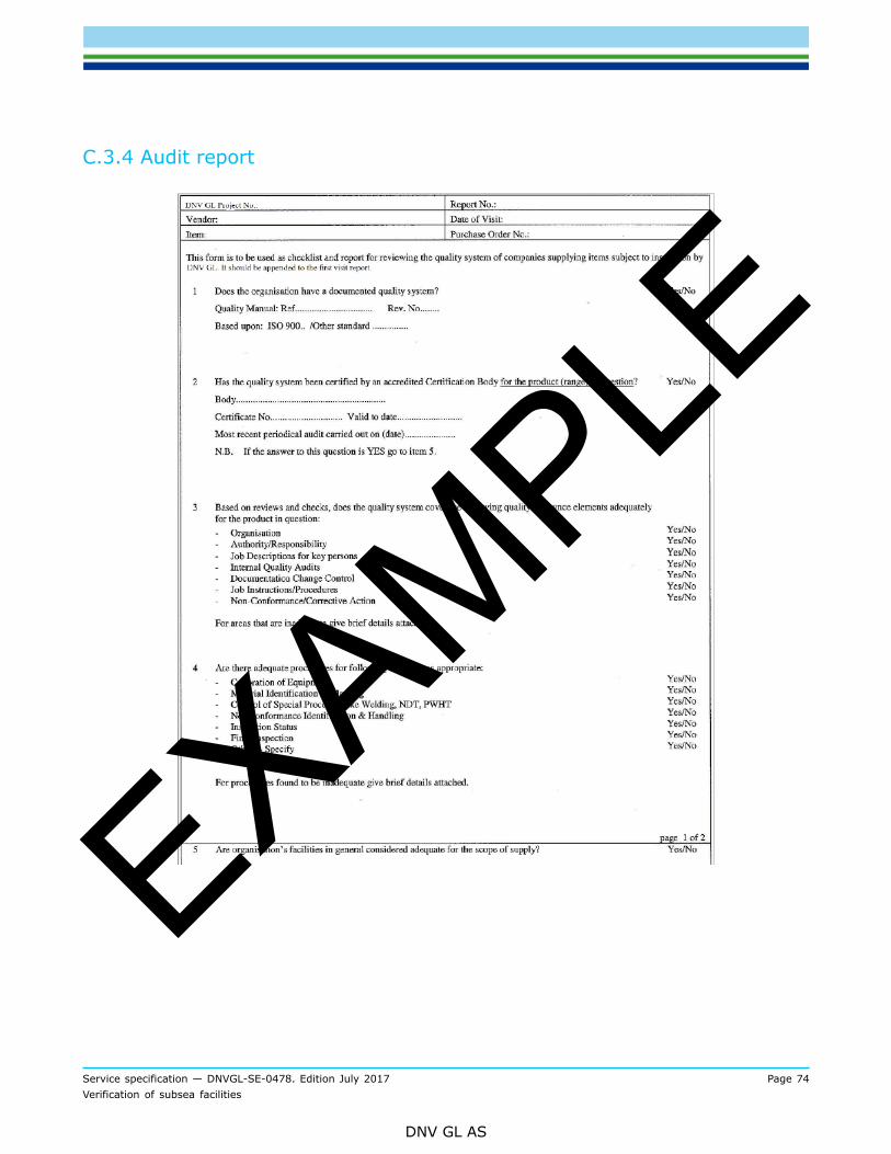
Service specification — DNVGL-SE-0478. Edition July 2017 Page 74Verification of subsea facilities
DNV GL AS
C.3.4 Audit report
EXAMPLE
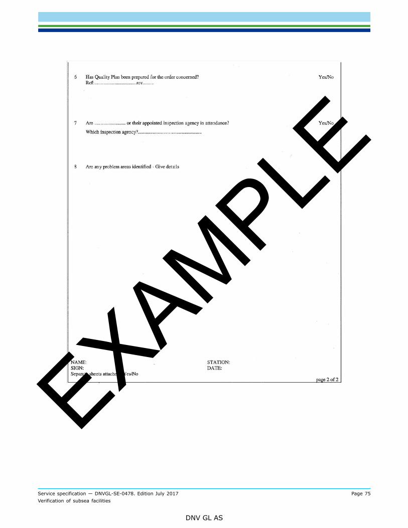
Service specification — DNVGL-SE-0478. Edition July 2017 Page 75Verification of subsea facilities
DNV GL AS
EXAMPLE
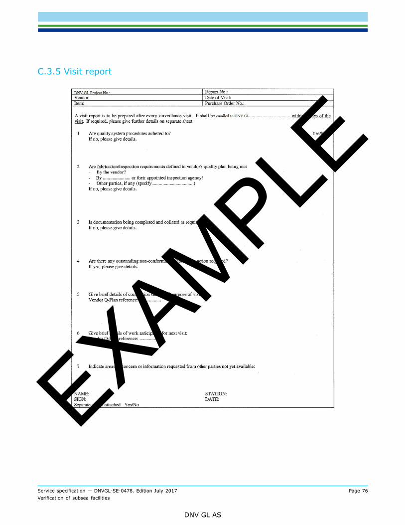
Service specification — DNVGL-SE-0478. Edition July 2017 Page 76Verification of subsea facilities
DNV GL AS
C.3.5 Visit report
EXAMPLE

Cha
nges
– h
isto
ric
Service specification — DNVGL-SE-0478. Edition July 2017 Page 77Verification of subsea facilities
DNV GL AS
CHANGES – HISTORICThere are currently no historical changes for this document.

About DNV GLDriven by our purpose of safeguarding life, property and the environment, DNV GL enablesorganizations to advance the safety and sustainability of their business. We provide classification,technical assurance, software and independent expert advisory services to the maritime, oil & gasand energy industries. We also provide certification services to customers across a wide rangeof industries. Operating in more than 100 countries, our experts are dedicated to helping ourcustomers make the world safer, smarter and greener.
SAFER, SMARTER, GREENER