DNV Ship rules Pt.5 Ch.3 - Oil Carriers · H. Chain Locker and Anchor Windlass ... B 500 Oil Record...
67
RULES FOR CLASSIFICATION OF DET NORSKE VERITAS Veritasveien 1, NO-1322 Høvik, Norway Tel.: +47 67 57 99 00 Fax: +47 67 57 99 11 SHIPS NEWBUILDING SPECIAL SERVICE AND TYPE ADDITIONAL CLASS PART 5 CHAPTER 3 OIL CARRIERS JANUARY 2011 CONTENTS PAGE Sec. 1 General Requirements .......................................................................................................... 8 Sec. 2 Materials and Hull Strength ............................................................................................... 14 Sec. 3 Ship Arrangement and Stability ......................................................................................... 21 Sec. 4 Piping Systems in Cargo Area .......................................................................................... 28 Sec. 5 Gas-freeing and Venting of Cargo Tanks .......................................................................... 33 Sec. 6 Ventilation Systems within the Cargo Area outside the Cargo Tanks............................... 35 Sec. 7 Fire Protection and Extinction ........................................................................................... 38 Sec. 8 Area Classification and Electrical Installations ................................................................. 39 Sec. 9 Instrumentation and Automation ...................................................................................... 43 Sec. 10 Ships for Alternate Carriage of Oil Cargo and Dry Cargo ................................................ 46 Sec. 11 Inert Gas Plants ................................................................................................................. 50 Sec. 12 Protected Slop Tank .......................................................................................................... 56 Sec. 13 Crude Oil Washing Arrangements ..................................................................................... 58 Sec. 14 Offshore Loading Arrangements ...................................................................................... 59 Sec. 15 Single Point Moorings ...................................................................................................... 64 App. A List of Cargoes ................................................................................................................... 66
Transcript of DNV Ship rules Pt.5 Ch.3 - Oil Carriers · H. Chain Locker and Anchor Windlass ... B 500 Oil Record...

RULES FORCLASSIFICATION OF
SHIPS
NEWBUILDING
SPECIAL SERVICE AND TYPEADDITIONAL CLASS
PART 5 CHAPTER 3
OIL CARRIERSJANUARY 2011
CONTENTS PAGE
Sec. 1 General Requirements.......................................................................................................... 8Sec. 2 Materials and Hull Strength ............................................................................................... 14Sec. 3 Ship Arrangement and Stability......................................................................................... 21Sec. 4 Piping Systems in Cargo Area .......................................................................................... 28Sec. 5 Gas-freeing and Venting of Cargo Tanks .......................................................................... 33Sec. 6 Ventilation Systems within the Cargo Area outside the Cargo Tanks............................... 35Sec. 7 Fire Protection and Extinction ........................................................................................... 38Sec. 8 Area Classification and Electrical Installations ................................................................. 39Sec. 9 Instrumentation and Automation ...................................................................................... 43Sec. 10 Ships for Alternate Carriage of Oil Cargo and Dry Cargo ................................................ 46Sec. 11 Inert Gas Plants ................................................................................................................. 50Sec. 12 Protected Slop Tank .......................................................................................................... 56Sec. 13 Crude Oil Washing Arrangements..................................................................................... 58Sec. 14 Offshore Loading Arrangements ...................................................................................... 59Sec. 15 Single Point Moorings ...................................................................................................... 64App. A List of Cargoes................................................................................................................... 66
DET NORSKE VERITASVeritasveien 1, NO-1322 Høvik, Norway Tel.: +47 67 57 99 00 Fax: +47 67 57 99 11

CHANGES IN THE RULES
GeneralThe present edition of the rules includes additions and amendments approved by the Executive Committee as of November2010, and supersedes the January 2009 edition of the same chapter.The rule changes come into force as indicated below.This chapter is valid until superseded by a revised chapter.
Main changes coming into force 1 January 2011• Sec.2 Materials and hull strength— A101 has been updated— A203 Reference to Pt.2 Ch.3 Sec.8 “Structural and Tightness Testing” has been added.
Corrections and ClarificationsIn addition to the above stated rule requirements, a number of corrections and clarifications have been made in the existingrule text.
The electronic pdf version of this document found through http://www.dnv.com is the officially binding version© Det Norske Veritas
Any comments may be sent by e-mail to [email protected] subscription orders or information about subscription terms, please use [email protected] Typesetting (Adobe Frame Maker) by Det Norske Veritas
If any person suffers loss or damage which is proved to have been caused by any negligent act or omission of Det Norske Veritas, then Det Norske Veritas shall pay compensation tosuch person for his proved direct loss or damage. However, the compensation shall not exceed an amount equal to ten times the fee charged for the service in question, provided thatthe maximum compensation shall never exceed USD 2 million.In this provision "Det Norske Veritas" shall mean the Foundation Det Norske Veritas as well as all its subsidiaries, directors, officers, employees, agents and any other acting on behalfof Det Norske Veritas.

Rules for Ships, January 2011 Pt.5 Ch.3 Contents – Page 3
CONTENTS
Sec. 1 General Requirements ....................................................................................................................... 8
A. Classification.................................................................................................................................................................. 8A 100 Scope..................................................................................................................................................................... 8A 200 Application............................................................................................................................................................ 8A 300 Class notations ..................................................................................................................................................... 8A 400 Special features notations ..................................................................................................................................... 9A 500 Register information ........................................................................................................................................... 10A 600 Structural and leak testing................................................................................................................................... 10
B. Definitions .................................................................................................................................................................... 10B 100 Terms .................................................................................................................................................................. 10
C. Documentation ............................................................................................................................................................ 11C 100 General................................................................................................................................................................ 11C 200 Plans and particulars ........................................................................................................................................... 11
D. Surveys and Testing .................................................................................................................................................... 12D 100 General................................................................................................................................................................ 12
E. Signboards ................................................................................................................................................................... 13E 100 References........................................................................................................................................................... 13
Sec. 2 Materials and Hull Strength............................................................................................................ 14
A. General ......................................................................................................................................................................... 14A 100 Application.......................................................................................................................................................... 14A 200 Common Structural Rules................................................................................................................................... 14A 300 Definitions .......................................................................................................................................................... 14
B. Materials and Corrosion Prevention......................................................................................................................... 14B 100 Selection and testing ........................................................................................................................................... 14
C. Hull Strength ............................................................................................................................................................... 15C 100 General................................................................................................................................................................ 15C 200 Design loads........................................................................................................................................................ 15C 300 Girders ................................................................................................................................................................ 15C 400 Lower hopper knuckle ........................................................................................................................................ 15C 500 Emergency towing .............................................................................................................................................. 15
D. Direct Strength Calculations...................................................................................................................................... 16D 100 General................................................................................................................................................................ 16D 200 Load conditions................................................................................................................................................... 16D 300 Acceptance criteria.............................................................................................................................................. 17
Sec. 3 Ship Arrangement and Stability ..................................................................................................... 21
A. Intact and Damage Stability....................................................................................................................................... 21A 100 Intact stability ..................................................................................................................................................... 21A 200 Damage stability ................................................................................................................................................. 21A 300 Watertight integrity............................................................................................................................................. 22
B. Location and Separation of Spaces............................................................................................................................ 22B 100 General................................................................................................................................................................ 22B 200 Arrangements of barges ...................................................................................................................................... 22
C. Tank and Pump Room Arrangement........................................................................................................................ 22C 100 Segregated ballast tanks...................................................................................................................................... 22C 200 Protection of cargo tanks .................................................................................................................................... 23C 300 Cargo tanks and slop tanks ................................................................................................................................. 24C 400 Double bottom in pump rooms ........................................................................................................................... 25
D. Arrangement of Access and Openings to Spaces and Tanks .................................................................................. 25D 100 Accommodation and non-hazardous spaces ....................................................................................................... 25D 200 Access to and within hazardous spaces .............................................................................................................. 25
E. Guard Rails and Bulwarks ........................................................................................................................................ 26E 100 Arrangement ....................................................................................................................................................... 26
F. Cofferdams and Pipe Tunnels.................................................................................................................................... 26F 100 Cofferdams.......................................................................................................................................................... 26F 200 Pipe tunnels......................................................................................................................................................... 26
DET NORSKE VERITAS

Rules for Ships, January 2011 Pt.5 Ch.3 Contents – Page 4
G. Diesel Engines for Emergency Fire Pumps............................................................................................................... 26G 100 General................................................................................................................................................................ 26
H. Chain Locker and Anchor Windlass ........................................................................................................................ 27H 100 General................................................................................................................................................................ 27
I. Equipment in Tanks and Cofferdams....................................................................................................................... 27I 100 General................................................................................................................................................................ 27
J. Surface Metal Temperatures in Hazardous Areas .................................................................................................. 27J 100 General................................................................................................................................................................ 27
Sec. 4 Piping Systems in Cargo Area ........................................................................................................ 28
A. Piping Materials .......................................................................................................................................................... 28A 100 Selection and testing ........................................................................................................................................... 28A 200 Special requirements for cargo piping system.................................................................................................... 28A 300 Plastic pipes in cargo area................................................................................................................................... 28A 400 Aluminium coatings............................................................................................................................................ 28
B. Bilge, Ballast and Fuel Oil Systems .......................................................................................................................... 28B 100 General................................................................................................................................................................ 28B 200 Drainage of pump rooms, cofferdams, pipe tunnels, ballast and fuel oil tanks.................................................. 28B 300 Fore peak ballast tank ......................................................................................................................................... 29B 400 Oil discharge monitoring and control systems ................................................................................................... 29B 500 Oil Record Book and SOPEP ............................................................................................................................. 29B 600 Air, sounding and filling pipes .......................................................................................................................... 29
C. Cargo Systems ............................................................................................................................................................. 30C 100 General................................................................................................................................................................ 30C 200 Piping systems .................................................................................................................................................... 30C 300 Cargo piping systems for barges......................................................................................................................... 31C 400 Testing ................................................................................................................................................................ 31
D. Cargo Heating ............................................................................................................................................................. 31D 100 General................................................................................................................................................................ 31D 200 Steam heating...................................................................................................................................................... 31D 300 Thermal oil heating ............................................................................................................................................. 32D 400 Heating of cargo with temperatures above 120°C ............................................................................................. 32
E. Bow and Stern Loading and Unloading Arrangements .......................................................................................... 32E 100 General................................................................................................................................................................ 32E 200 Piping arrangement ............................................................................................................................................. 32
Sec. 5 Gas-freeing and Venting of Cargo Tanks ...................................................................................... 33
A. Gas-freeing of Cargo Tanks ...................................................................................................................................... 33A 100 General................................................................................................................................................................ 33A 200 Gas-freeing of cargo tanks for barges................................................................................................................. 33
B. Cargo Tank Venting Systems..................................................................................................................................... 34B 100 General................................................................................................................................................................ 34B 200 System design ..................................................................................................................................................... 34B 300 Venting of cargo tanks for barges....................................................................................................................... 34
Sec. 6 Ventilation Systems within the Cargo Area outside the Cargo Tanks........................................ 35
A. Ventilation Systems..................................................................................................................................................... 35A 100 General ............................................................................................................................................................... 35A 200 Fans serving hazardous spaces............................................................................................................................ 35
B. Ventilation Arrangement and Capacity Requirements........................................................................................... 36B 100 General................................................................................................................................................................ 36B 200 Non-hazardous spaces......................................................................................................................................... 36B 300 Cargo handling spaces ....................................................................................................................................... 36B 400 Other hazardous spaces normally entered........................................................................................................... 37B 500 Spaces not normally entered ............................................................................................................................... 37B 600 Ventilation systems for barges............................................................................................................................ 37
Sec. 7 Fire Protection and Extinction........................................................................................................ 38
A. Fire Safety Measures for Tankers ............................................................................................................................. 38A 100 Application.......................................................................................................................................................... 38
DET NORSKE VERITAS

Rules for Ships, January 2011 Pt.5 Ch.3 Contents – Page 5
Sec. 8 Area Classification and Electrical Installations ............................................................................ 39
A. General ......................................................................................................................................................................... 39A 100 Application.......................................................................................................................................................... 39A 200 Insulation monitoring.......................................................................................................................................... 39
B. Electrical Installations in Hazardous Areas ............................................................................................................. 39B 100 General................................................................................................................................................................ 39
C. Area Classification ...................................................................................................................................................... 39C 100 General................................................................................................................................................................ 39C 200 Tankers for carriage of products with flashpoint not exceeding 60°C ............................................................... 40C 300 Tankers for carriage of products with flashpoint exceeding 60°C ..................................................................... 41
D. Inspection and Testing................................................................................................................................................ 41D 100 General................................................................................................................................................................ 41
E. Maintenance ................................................................................................................................................................ 41E 100 General................................................................................................................................................................ 41
F. Signboards ................................................................................................................................................................... 42F 100 General................................................................................................................................................................ 42
Sec. 9 Instrumentation and Automation .................................................................................................. 43
A. General Requirements ................................................................................................................................................ 43A 100 General................................................................................................................................................................ 43
B. Cargo Valve and Pump Control ................................................................................................................................ 43B 100 General................................................................................................................................................................ 43B 200 Computer based systems for cargo handling ...................................................................................................... 43B 300 Centralised cargo control .................................................................................................................................... 43B 400 Design of integrated cargo and ballast systems .................................................................................................. 43
C. Cargo Tank Level Measurement ............................................................................................................................... 44C 100 General................................................................................................................................................................ 44
D. Cargo Tank Overflow Protection .............................................................................................................................. 44D 100 General................................................................................................................................................................ 44
E. Oil and Water Interface Detector.............................................................................................................................. 44E 100 General................................................................................................................................................................ 44
F. Gas Detection in Cargo Pump Room ........................................................................................................................ 45F 100 General................................................................................................................................................................ 45
G. Explosimeters and Gas Detectors .............................................................................................................................. 45G 100 General................................................................................................................................................................ 45
H. Installation Requirements for Analysing Units........................................................................................................ 45H 100 General................................................................................................................................................................ 45
Sec. 10 Ships for Alternate Carriage of Oil Cargo and Dry Cargo.......................................................... 46
A. General ......................................................................................................................................................................... 46A 100 Application.......................................................................................................................................................... 46A 200 Class notation...................................................................................................................................................... 46A 300 Basic assumptions............................................................................................................................................... 46A 400 Documentation.................................................................................................................................................... 46
B. Cargo Area Arrangement and Systems .................................................................................................................... 46B 100 General................................................................................................................................................................ 46B 200 Design of cargo oil tanks .................................................................................................................................... 47B 300 Arrangement and access to compartments.......................................................................................................... 47B 400 Bilge, drainage and cargo piping ........................................................................................................................ 47B 500 Cleaning and gas-freeing .................................................................................................................................... 48B 600 Ventilation .......................................................................................................................................................... 48
C. Gas Measuring Equipment ........................................................................................................................................ 48C 100 Measurement of hydrocarbon gases.................................................................................................................... 48
D. Instructions .................................................................................................................................................................. 48D 100 Instruction manual .............................................................................................................................................. 48D 200 Instructions onboard ........................................................................................................................................... 49
DET NORSKE VERITAS

Rules for Ships, January 2011 Pt.5 Ch.3 Contents – Page 6
Sec. 11 Inert Gas Plants ............................................................................................................................... 50
A. General ......................................................................................................................................................................... 50A 100 Application.......................................................................................................................................................... 50A 200 Documentation.................................................................................................................................................... 50A 300 Instruction manual .............................................................................................................................................. 50
B. Materials ...................................................................................................................................................................... 50B 100 General................................................................................................................................................................ 50
C. Arrangement and General Design............................................................................................................................. 50C 100 General................................................................................................................................................................ 50C 200 Piping arrangement ............................................................................................................................................. 51C 300 Inerting of double hull spaces ............................................................................................................................ 52C 400 Fresh air intakes .................................................................................................................................................. 52C 500 Level measuring of inerted tanks........................................................................................................................ 52C 600 Prevention of gas leakage into non-hazardous spaces ........................................................................................ 52
D. Inert Gas Production and Treatment........................................................................................................................ 52D 100 General................................................................................................................................................................ 52D 200 Flue gas system................................................................................................................................................... 53D 300 Inert gas generator............................................................................................................................................... 53D 400 Gas cleaning and cooling .................................................................................................................................... 53D 500 Water supply ....................................................................................................................................................... 53D 600 Water discharge .................................................................................................................................................. 53
E. Instrumentation........................................................................................................................................................... 54E 100 General................................................................................................................................................................ 54E 200 Indication ............................................................................................................................................................ 54E 300 Monitoring .......................................................................................................................................................... 54
F. Survey and Testing...................................................................................................................................................... 55F 100 Survey ................................................................................................................................................................. 55F 200 Testing ................................................................................................................................................................ 55
Sec. 12 Protected Slop Tank ........................................................................................................................ 56
A. General ......................................................................................................................................................................... 56A 100 Application.......................................................................................................................................................... 56A 200 Documentation.................................................................................................................................................... 56
B. Arrangement and Systems ......................................................................................................................................... 56B 100 Arrangement ....................................................................................................................................................... 56B 200 Tank venting ....................................................................................................................................................... 56B 300 Pumping and piping system................................................................................................................................ 56B 400 Gas detection....................................................................................................................................................... 56B 500 Protection inside slop tanks ................................................................................................................................ 56
C. Signboards and Instructions ...................................................................................................................................... 57C 100 General................................................................................................................................................................ 57
Sec. 13 Crude Oil Washing Arrangements ................................................................................................. 58
A. General ......................................................................................................................................................................... 58A 100 Application.......................................................................................................................................................... 58A 200 Documentation.................................................................................................................................................... 58
Sec. 14 Offshore Loading Arrangements ................................................................................................... 59
A. General ......................................................................................................................................................................... 59A 100 Application.......................................................................................................................................................... 59A 200 Class notation...................................................................................................................................................... 59A 300 Documentation.................................................................................................................................................... 59
B. Materials ...................................................................................................................................................................... 59B 100 General................................................................................................................................................................ 59
C. Arrangement and General Design............................................................................................................................. 59C 100 Positioning of ship .............................................................................................................................................. 59C 200 Piping system for bow loading ........................................................................................................................... 60C 300 Hazardous areas .................................................................................................................................................. 60
D. Control and Monitoring ............................................................................................................................................. 60D 100 General................................................................................................................................................................ 60D 200 Control station..................................................................................................................................................... 60
DET NORSKE VERITAS
Rules for Ships, January 2011 Pt.5 Ch.3 Contents – Page 7
D 300 Instrumentation and automation ......................................................................................................................... 60D 400 Communication................................................................................................................................................... 61
E. Bow Loading Area Safety Installations..................................................................................................................... 61E 100 General................................................................................................................................................................ 61
F. STL Room Safety Installations .................................................................................................................................. 62F 100 General................................................................................................................................................................ 62
G. Operation Manual....................................................................................................................................................... 62G 100 General................................................................................................................................................................ 62
H. Tests after Installation ................................................................................................................................................ 63H 100 General................................................................................................................................................................ 63
Sec. 15 Single Point Moorings ..................................................................................................................... 64
A. General ......................................................................................................................................................................... 64A 100 Application.......................................................................................................................................................... 64A 200 Class notation...................................................................................................................................................... 64A 300 Documentation.................................................................................................................................................... 64
B. Materials ...................................................................................................................................................................... 64B 100 General................................................................................................................................................................ 64
C. Arrangement and General Design............................................................................................................................. 64C 100 Bow chain stoppers ............................................................................................................................................. 64C 200 Bow fairleads ...................................................................................................................................................... 65C 300 Position of pedestal rollers.................................................................................................................................. 65C 400 Winches or capstans............................................................................................................................................ 65C 500 Winch storage drum............................................................................................................................................ 65
App. A List of Cargoes .................................................................................................................................. 66
A. List of Oil Cargoes ...................................................................................................................................................... 66A 100 General................................................................................................................................................................ 66
B. Cargoes other than Oils .............................................................................................................................................. 67B 100 Cargoes and conditions for carriage ................................................................................................................... 67
DET NORSKE VERITAS

Rules for Ships, January 2011 Pt.5 Ch.3 Sec.1 – Page 8
SECTION 1 GENERAL REQUIREMENTS
A. Classification
A 100 Scope101 The rules in this chapter govern safety hazards, marine pollution hazards and functional capability ofsystems. Incorporated in the rules are some requirements of SOLAS Ch. II-2, where these are specificallymentioned as applicable for tankers only, and the requirements in MARPOL 73/78 Annex I, insofar design andequipment are concerned.
A 200 Application201 These rules apply to ships intended for carriage of liquid cargoes in bulk with a flash point not exceeding60°C (closed cup test). Cargoes with a flash point exceeding 60°C, where the cargoes are heated to atemperature above their flash point shall be especially considered.For ships intended for carriage of oil products regardless of flash point the requirements in Sec.2, Sec.3, Sec.4and Sec.9 shall be complied with.Liquid cargoes with vapour pressure above atmospheric pressure at 37.8°C shall not be carried unless the shipis especially designed and equipped.Relevant requirements may be found in Ch.4; e.g. Sec.1 D, Sec.7 and Sec.15 B200.The requirements shall be regarded as supplementary to those given for the assignment of main class.202 Oil cargoes and cargoes other than oils covered by the classification in accordance with this chapter arelisted in App.A.203 Exemptions from the rules in this chapter may be granted for heated cargoes where found justifiable, forinstance with respect to electrical equipment on open decks.204 Oil carriers of 20 000 tonnes dwt and above and all ships fitted with equipment for crude oil washingshall fulfil the requirements for inert gas plants as given in Sec.11.205 Ships for alternate carriage of oil cargo and dry cargo shall comply with the requirements for protectedslop tanks given in Sec.12.206 Ships intended to carry liquid cargoes with a flash point not exceeding 60°C or dry cargo alternatively,shall comply with the requirements in Sec.10.207 Tanks for cargoes with specific gravity exceeding 1 025 kg/m3, see Pt.3 Ch.1.
A 300 Class notations 301 The mandatory ship type and service notation Tanker for Oil ESP shall be assigned to sea-going shipshaving integral tanks and intended for the carriage of oil in bulk. 302 The mandatory ship type and service notation Tanker for Oil Products ESP shall be assigned to shipsintended for the carriage of all types of oil products except crude oil.303 The general term combination carrier is applied to ships intended for the carriage of oil and dry cargoes in bulk.It is assumed, however, that dry cargoes and oil cargoes will not be carried simultaneously, with the exception of oilretained in slop tanks.The mandatory ship type and service notation Bulk Carrier or Tanker for Oil ESP (alternatively Tankerfor Oil Products ESP) shall be assigned to single deck ships of double skin construction, with a doublebottom, hopper side tanks and topside tanks fitted below the upper deck, and intended for the carriage of oil ordry cargoes in bulk. The mandatory ship type and service notation Ore Carrier or Tanker for Oil ESP (alternatively Tankerfor Oil Products ESP) shall be assigned to sea-going single deck ships having two longitudinal bulkheadsand a double bottom and double skin throughout the cargo region, and intended for the carriage of ore cargoesin the centre holds or of oil cargoes in the centre holds and wing tanks. The ships shall comply with Sec.1 to Sec.13 of this chapter, except Sec.13 when only oil products are carried.304 Ships having a bow loading arrangement will be assigned the additional notation BOW LOADING andshall meet the relevant requirements in Sec.14.305 Ships having a submerged turret loading arrangement (STL) will be assigned the additional notationSTL. and shall meet the relevant requirements in Sec.14.
DET NORSKE VERITAS

Rules for Ships, January 2011 Pt.5 Ch.3 Sec.1 – Page 9
306 Ships having equipment enabling them to be moored to single point moorings will be assigned theadditional notation SPM and shall meet the relevant requirements in Sec.15.307 Arrangements for efficient cleaning of tanks when changing from dirty to clean oil cargoes.Ships having cargo tanks, systems and cleaning arrangement satisfying the following conditions will beassigned the additional notation ETC:
— Tanks shall be designed with smooth surfaces. Under deck longitudinals of slab type are acceptable.Horizontal areas on stiffeners and brackets are generally not acceptable.Bulkheads may have horizontal or vertical corrugations. Horizontally corrugated bulkheads shouldnormally not have an angle of the corrugations in excess of 45 degrees related to the vertical plane, seeFig.1. Bulkheads with larger angles - but not more than 65 degrees - might be accepted taking intoconsideration the location of washing machines in the tanks and the shadow diagrams.Vertical girders in horizontally corrugated bulkheads may also be accepted after special consideration.
— Tanks are of stainless steel or coated.— Cargo piping is of stainless steel.— Heating coils are of stainless steel or equivalent material.— Capability of cargo tank washing with hot water of min 85°C with a capacity sufficient for washing at least
the largest cargo tank.— Cargo tanks served by individual in-tank cargo pumps.— Cargo suction wells to be located for optimum drainage results.— Permanently installed tank washing machines giving minimum coverage of 96% based on effective jet
length at normal operating pressure according to DNV Type Approval Programme 785.70.For calculation of coverage, shadow areas shall include areas where the angle between jet and tank surfaceis less than 10 degrees, and shadow from cargo pump stacks.Heating coils and ladders shall not be included in the shadow areas. Areas where the angle between jet and tank surface is less than 10 degrees, shall be considered shadowareas.In addition to the permanent washing machines, portable washing equipment and necessary accessopenings enabling complete washing of shadow areas shall be provided. The additional washing to becarried out without need for tank entry.
Fig. 1Definition of corrugation angle, horizontally corrugated bulkhead
A 400 Special features notations401 Oil carriers less than 20 000 tons deadweight fitted with inert gas system complying with therequirements in Sec.11 may be assigned the special features notation INERT.402 Noxious Liquid Substances NLSThe notation implies that the ship is acceptable for an NLS certificate in accordance with MARPOL Annex IIfor carriage of IBC Code Ch.18, Category Z products, and:
a) complies with the requirements of Ch.4 Sec.1 A309 in respect of cargo stripping efficiency str 0.075,b) is provided with an underwater discharge outlet in compliance with Ch.4 Sec.6 D200,c) is provided with a procedures and arrangements manual in compliance with Ch.4 Sec.1 H100, and
Corrugation angle
Vertical profile
DET NORSKE VERITAS
Rules for Ships, January 2011 Pt.5 Ch.3 Sec.1 – Page 10
d) is provided with a cargo record book in accordance with Ch.4 Sec.6 D300.
A 500 Register information501 Materials of construction (ssp)The notation ssp indicates that cargo piping and all equipment in contact with cargo and cargo vapours is made ofstainless steel.
A 600 Structural and leak testing601 Testing shall be in accordance with Pt.2 Ch.3 Sec.8 Table B1.
B. Definitions
B 100 Terms101 Accommodation spaces are those used for public spaces, corridors, lavatories, cabins, offices, hospital,cinemas, games and hobbies rooms, pantries containing no cooking appliances and similar spaces. Publicspaces are those portions of the accommodation which are used as halls, dining rooms, lounges and similarpermanently enclosed spaces.102 An air lock is an enclosed space for entrance between an hazardous area on open deck and a non-hazardous space, arranged to prevent ingress of gas to the non-hazardous space. 103 Cargo area is that part of the ship which contains the cargo tanks, pump rooms and or cofferdamsadjacent to cargo tanks, and includes deck areas over the full beam and length of above spaces. 104 Cargo control room is a space used in the control of cargo handling operations. 105 Cargo handling spaces are pump rooms and other enclosed spaces which contain fixed cargo handlingequipment, and similar spaces in which work is performed on the cargo.106 Cargo tank is the liquid-tight shell designed to be the primary container of the cargo.107 Cofferdam is the isolating space between two adjacent steel bulkheads or decks. This space may be a dryspace or a tank, see Sec.3 F100. 108 Control stations are those spaces in which the ship's radio or main navigating equipment or theemergency source of power is located or where the fire recording or fire control equipment is centralised.109 Design vapour pressure p0 is the maximum gauge pressure at the top of the tank which has been used inthe design of the tank.110 Flame arrester is a device through which an external flame front cannot propagate and ignite an internalgas mixture.111 A flame screen is a flame arrester, consisting of a fine-meshed wire gauze of corrosion-resistant material.112 Hazardous areaArea in which an explosive gas atmosphere is or may be expected to be present, in quantities such as to requirespecial precautions for the construction, installation and use of electrical apparatus.Hazardous areas are divided into Zone 0, 1 and 2 as defined below and according to area classification specifiedin Sec.8 C.
— Zone 0Area in which an explosive gas atmosphere is present continuously or is present for long periods.
— Zone 1Area in which an explosive gas atmosphere is likely to occur in normal operation.
— Zone 2Area in which an explosive gas atmosphere is not likely to occur in normal operation and, if it does occur,is likely to do so only infrequently and will exist for a short period only.
113 A high velocity vent valve is a cargo tank vent valve which at all flow rates expels the cargo vapourupwards at a velocity of at least 30 m/s, measured at a distance equal to the nominal diameter of the standpipeabove the valve outlet opening.114 Non-hazardous area. An area not considered to be hazardous.115 A pressure-vacuum (P/V) valve is a valve which keeps the tank overpressure or under-pressure withinapproved limits.
DET NORSKE VERITAS

Rules for Ships, January 2011 Pt.5 Ch.3 Sec.1 – Page 11
116 Segregated ballast tanks are tanks which are completely separated from the cargo oil and fuel oil systemsand which are permanently allocated to the carriage of ballast or cargoes other than oil or noxious substancesas defined in MARPOL 73/78.117 Service spaces are spaces used for galleys, pantries containing cooking appliances, lockers and storerooms, workshops other than those forming part of the machinery spaces and similar spaces and trunks to suchspaces.118 Slop tanks are tanks particularly designated for the collection of tank draining, tank washing and otheroily mixtures.119 Spaces not normally entered are cofferdams, double bottoms, duct keels, pipe tunnels, stool tanks, spacescontaining cargo tanks and other spaces where cargo may accumulate.120 A spark arrester is a device which prevents sparks from the combustion in prime movers, boilers etc.from reaching the open air.121 The following decks are designated tank deck:
— a deck or part of a deck which forms the top of a cargo tank— the part of a deck upon which are located cargo tanks, cargo hatches, valves, pumps or other equipment
intended for loading, discharging or transfer of the cargo— that part of a deck within the cargo area, which is located lower than the top of a cargo tank— deck or part of deck within the cargo area, which is located lower than 2.4 m above a deck as described
above.
122 Tank types, definition see Ch.4 Sec.1 D.123 Void space is an enclosed space not forming a cargo tank, ballast space, fuel oil tank, cargo pump room,or any space in normal use by personnel.
C. DocumentationC 100 General101 In 200 are specified the plans and particulars which normally shall be submitted when the additional classnotations as given in A are applied for.The drawings shall show clearly that the requirements are fulfilled.102 Other plans, specifications or information may be required depending on the arrangement and theequipment used in each separate case.103 For general requirements related to documentation of instrumentation and automation, includingcomputer based control and monitoring, see Pt.4 Ch.9 Sec.1.
C 200 Plans and particulars201 A general arrangement shall be submitted for approval giving location of:
— cargo hatches, butterworth hatches and any other openings to cargo tanks— doors, hatches and any other openings to pump rooms and other hazardous areas— ventilating pipes and openings for cargo hatches, pump rooms and other hazardous areas— doors, air locks, hatches, ventilating pipes and openings, hinged scuttles which can be opened, and other
openings to non-hazardous spaces adjacent to the cargo area including spaces in and below the forecastle— cargo oil pipes over the deck with shore connections including stern pipes for cargo discharge or pipes for
bow loading arrangement— hazardous areas of zone 0, 1 and 2, and their extent.
202 Plans of the following pumping and piping arrangements shall be submitted for approval:
— cargo piping system including drawings of details such as expansion elements and flange connections— hydraulic system for cargo pumps— bilge piping systems in pump rooms, cofferdams, pipe tunnels and other dry spaces within cargo area— pumping and piping arrangement in the forward end of the ship and to permanent ballast tanks within cargo
area.
203 Plans showing the following equipment and systems shall be submitted for approval:
— arrangement of cargo heating systems
DET NORSKE VERITAS

Rules for Ships, January 2011 Pt.5 Ch.3 Sec.1 – Page 12
— arrangement for gas-freeing of cargo tanks— arrangement for cargo tank venting systems— pressure-vacuum valves and high velocity vent valves (or reference to possible type approval)— arrangement and capacity of air ducts, fans and their motors in the cargo area— fan rotating parts and casing— details of valve actuators (or reference to possible type approval)— gastight bulkhead stuffing boxes.
204 Plans of electrical installations giving the following particulars shall be submitted for approval:
— area classification drawing(s)— drawing(s) showing location of all electrical equipment in hazardous areas— single line diagram for intrinsically safe circuits and data for verification of the compatibility between the
barrier and the field component— list of explosion protected equipment with reference to drawings. See also Pt.4 Ch.8 Sec.11, Table B1— maintenance manual as specified in Sec.8 E101, for electrical installations in hazardous areas shall be
submitted for approval.
205 For documentation regarding:
— combination carriers, see Sec.10— inert gas plants, see Sec.11— slop tanks in combination carriers, see Sec.12— crude oil washing, see Sec.13— offshore loading, see Sec.14.
206 For damage stability, the following documentation shall be submitted for approval:
— preliminary damage stability calculations— final damage stability calculations.
This is not required in case of approved limit curves, or if approved lightweight data are not less favourablethan estimated lightweight data.The following documentation shall be submitted for information:
— internal watertight integrity plan.
Detailed description of stability documentation is given in Classification Note 20.1.
207 The following documentation is to be submitted for information:
— Calculations of hypothetical outflow of oil in case of side damage and bottom damage. Ref. MARPOL 73/78Annex I Reg. 25.
— Calculations of limit values and arrangement of cargo tanks. Ref. MARPOL 73/78 Annex I Reg. 26.
208 The following control and monitoring systems shall be approved by the Society:
— cargo and vapour temperature control and monitoring system— cargo tank level measurement system— cargo tank overflow protection system— cargo valves and pumps control and monitoring system— flammable gas detection system (permanent system only)— inert gas control and monitoring system— offshore loading and unloading control and monitoring system— oil discharge control and monitoring system— cargo tank oil/water interface detection system.
For requirements to documentation, see Pt.4 Ch.9.
D. Surveys and Testing
D 100 General
101 All systems covered by this chapter are as far as possible, to be function tested under working conditionsto the satisfaction of the surveyor.
DET NORSKE VERITAS

Rules for Ships, January 2011 Pt.5 Ch.3 Sec.1 – Page 13
E. SignboardsE 100 References101 Signboards are required by the rules in:
— Sec.3 D101 regarding plates bolted to boundaries facing the cargo area and which can be opened forremoval of machinery. These shall be supplied with signboards giving instruction that the plates shall bekept closed unless ship is gas-free.
— Sec.8 F101 regarding opening of a lighting fitting. Before opening its supply circuit shall be disconnected.— Sec.8 F102 regarding spaces where the ventilation must be in operation before the lighting is turned on.— Sec.8 F103 regarding portable electrical equipment supplied by flexible cables. This equipment shall not
be used in areas where there is gas danger.— Sec.8 F104 regarding welding apparatus. These shall not be used unless the working space and adjacent
spaces are gas-free.— Sec.10 B304 regarding access to stool tanks.— Sec.12 C101 regarding hatches and other openings to cargo slop tanks. These shall be kept closed and
locked during handling of dry cargo.— Sec.12 C102 regarding instructions for handling of slop.
DET NORSKE VERITAS

Rules for Ships, January 2011 Pt.5 Ch.3 Sec.2 – Page 14
SECTION 2 MATERIALS AND HULL STRENGTH
A. GeneralA 100 Application101 Requirements with respect to strength of the hull structure and selection of hull materials are in general to followthe requirements and principles given in Pt.3 Ch.1 or Pt.3 Ch.2 supplemented by the requirements given in this section.For scantlings and testing of tanks other than integral tanks, see Ch.5 Sec.5.102 The additional notation CSR is mandatory for tankers and combination carriers with class notations andlength as described below:
— ships with class notation Tanker for Oil or Tanker for Oil Products and with L ≥ 150 m.
This includes combination carriers and chemical tankers with L ≥ 150 m, also intended for carriage of oil.The CSR notation describes that the newbuilding is designed and built according to Common Structural Rulesfor Double Hull Oil Tankers as described in A200.L = length as given in Pt.3 Ch.1 Sec.1 B101.103 The additional notation NAUTICUS(Newbuilding) may be given to tankers except in combinationwith CSR.NAUTICUS(Newbuilding) is described in Pt.3 Ch.1 Sec.15 and comprises extended fatigue calculations andextended direct strength calculations.
A 200 Common Structural Rules201 CSR is described in Pt.8 Ch.1 “Common Structural Rules for Double Hull Oil Tankers”, and comprisesthe scantling requirements for the classification of new tankers.202 Requirements with respect to strength of the hull structure, including scantlings and testing of integraltanks and selection of hull materials given in Pt.3 Ch.1 and the requirements given in B, C, and D below arenot applicable for vessels with CSR notation.203 The following requirements are in addition covered by the common structural rules and are notapplicable for vessels with CSR notation:
Pt.2 Ch.3 Sec.8 Structural and Tightness TestingPt.3 Ch.3 Sec.3 Anchoring and Mooring EquipmentPt.3 Ch.3 Sec.6 Opening and Closing AppliancesPt.3 Ch.3 Sec.7 Corrosion PreventionPt.3 Ch.3 Sec.8 Protection of the Crew.204 For regions of the structure for which the common structural rules do not apply, the appropriateclassification rules shall be applied. In cases where the common structural rules do not address certain aspectsof the ship's design, the applicable classification rules shall be applied.205 Optional design feature notations described in Pt.3 Ch.1 may be given to vessels with CSR notation.206 Combination carriers with class notation Bulk Carrier or Tanker for Oil ESP or Ore Carrier orTanker for Oil ESP shall fulfil design requirements for bulk carrier or ore carrier in addition to the commonstructural rules for double hull oil tankers.
A 300 Definitions301 The following symbols are used:
TA = minimum relevant seagoing draught (depending on the loading condition in question)LF = ship length as given in Pt.3 Ch.1 Sec.1 B101D = moulded depth as given in Pt.3 Ch.1 Sec.1 B101.
B. Materials and Corrosion PreventionB 100 Selection and testing101 Materials are generally to be selected according requirements given in Pt.3 Ch.1 Sec.2 for hull materials.
DET NORSKE VERITAS
Rules for Ships, January 2011 Pt.5 Ch.3 Sec.2 – Page 15
The selected materials shall be tested according to the requirements in Pt.2.102 Other materials may be accepted after special consideration.103 Specifications for corrosion prevention systems for water ballast tanks, comprising selection, applicationand maintenance, as defined in Pt.3 Ch.3 Sec.7 Table A1, shall be submitted for information for all vesselsdesigned to carry products listed in Ch.3.
C. Hull StrengthC 100 General101 Design of structures are in general to follow requirements and principles as given in Pt.3.
C 200 Design loads201 Design loads are in general to be taken as described in Pt.3 Ch.1 or Pt.3 Ch.2.
C 300 Girders301 Scantlings of girders shall be based on requirements given in Pt.3 Ch.1 or Pt.3 Ch.2 and the principlesfor direct calculations as given in this section.
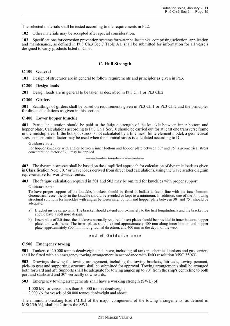
C 400 Lower hopper knuckle401 Particular attention should be paid to the fatigue strength of the knuckle between inner bottom andhopper plate. Calculations according to Pt.3 Ch.1 Sec.16 should be carried out for at least one transverse framein the midship area. If the hot spot stress is not calculated by a fine mesh finite element model, a geometricalstress concentration factor may be used when the nominal stress is calculated according to D.
Guidance note:For hopper knuckles with angles between inner bottom and hopper plate between 30° and 75° a geometrical stressconcentration factor of 7.0 may be applied.
---e-n-d---of---G-u-i-d-a-n-c-e---n-o-t-e---
402 The dynamic stresses shall be based on the simplified approach for calculation of dynamic loads as givenin Classification Note 30.7 or wave loads derived from direct load calculations, using the wave scatter diagramrepresentative for world-wide routes.403 The fatigue calculation required in 501 and 502 may be omitted for knuckles with proper support.
Guidance note:To have proper support of the knuckle, brackets should be fitted in ballast tanks in line with the inner bottom.Geometrical eccentricity in the knuckle should be avoided or kept to a minimum. In addition, one of the followingstructural solutions for knuckles with angles between inner bottom and hopper plate between 30° and 75°, should beadequate:
a) Bracket inside cargo tank. The bracket should extend approximately to the first longitudinals and the bracket toeshould have a soft nose design.
b) Insert plate of 2.0 times the thickness normally required. Insert plates should be provided in inner bottom, hopperplate, and web frame. The insert plates should extend approximately 400 mm along inner bottom and hopperplate, approximately 800 mm in longitudinal direction, and 400 mm in the depth of the web.
---e-n-d---of---G-u-i-d-a-n-c-e---n-o-t-e---
C 500 Emergency towing501 Tankers of 20 000 tonnes deadweight and above, including oil tankers, chemical tankers and gas carriersshall be fitted with an emergency towing arrangement in accordance with IMO resolution MSC.35(63).502 Drawings showing the towing arrangement, including the towing brackets, fairleads, towing pennant,pick-up gear and supporting structure shall be submitted for approval. Towing arrangements shall be arrangedboth forward and aft. Supports shall be adequate for towing angles up to 90° from the ship's centreline to bothport and starboard and 30° vertically downwards.503 Emergency towing arrangements shall have a working strength (SWL) of:
— 1 000 kN for vessels less than 50 000 tonnes deadweight— 2 000 kN for vessels of 50 000 tonnes deadweight and above.
The minimum breaking load (MBL) of the major components of the towing arrangements, as defined inMSC.35(63), shall be 2 times the SWL.
DET NORSKE VERITAS

Rules for Ships, January 2011 Pt.5 Ch.3 Sec.2 – Page 16
504 The strong point and supporting structure for the towing arrangement shall be designed for a load of 1.3times the SWL with allowable stresses as follows:
505 Material of welded parts used in the strong point shall be Charpy V-notch tested (minimum 27 J at0 deg.), ref. Pt.2 Ch.1 Sec.2.506 The pick-up gear shall be a floating line of minimum length 120 m and with a minimum breaking load(MBL) of 200 kN.
D. Direct Strength CalculationsD 100 General101 For girders that are part of a complex 2 or 3 dimensional structural system, a complete structural analysismay have to be carried out to demonstrate that the stresses are acceptable when the structure is loaded asdescribed in 200.102 Calculations as mentioned in 101 shall be carried out for:
— transverse and vertical girders in cargo tanks— transverse bulkhead structure— double bottom structures— other structures as deemed necessary by the Society.
D 200 Load conditions201 The girder structure in the cargo region of oil carriers and chemical carriers is generally to be consideredfor load conditions given in 202 to 205.202 Load conditions following the principles below shall be examined for upright seagoing conditions:
a) Any cargo tank to be empty on full draught (T) with adjacent cargo tanks full.b) Any cargo tank to be filled on a minimum relevant seagoing draught (TA) with the adjacent tanks empty.c) All cargo tanks within a transverse section of the ship to be filled on minimum relevant seagoing draught
(TA) with adjoining cargo tanks forward and aft empty.
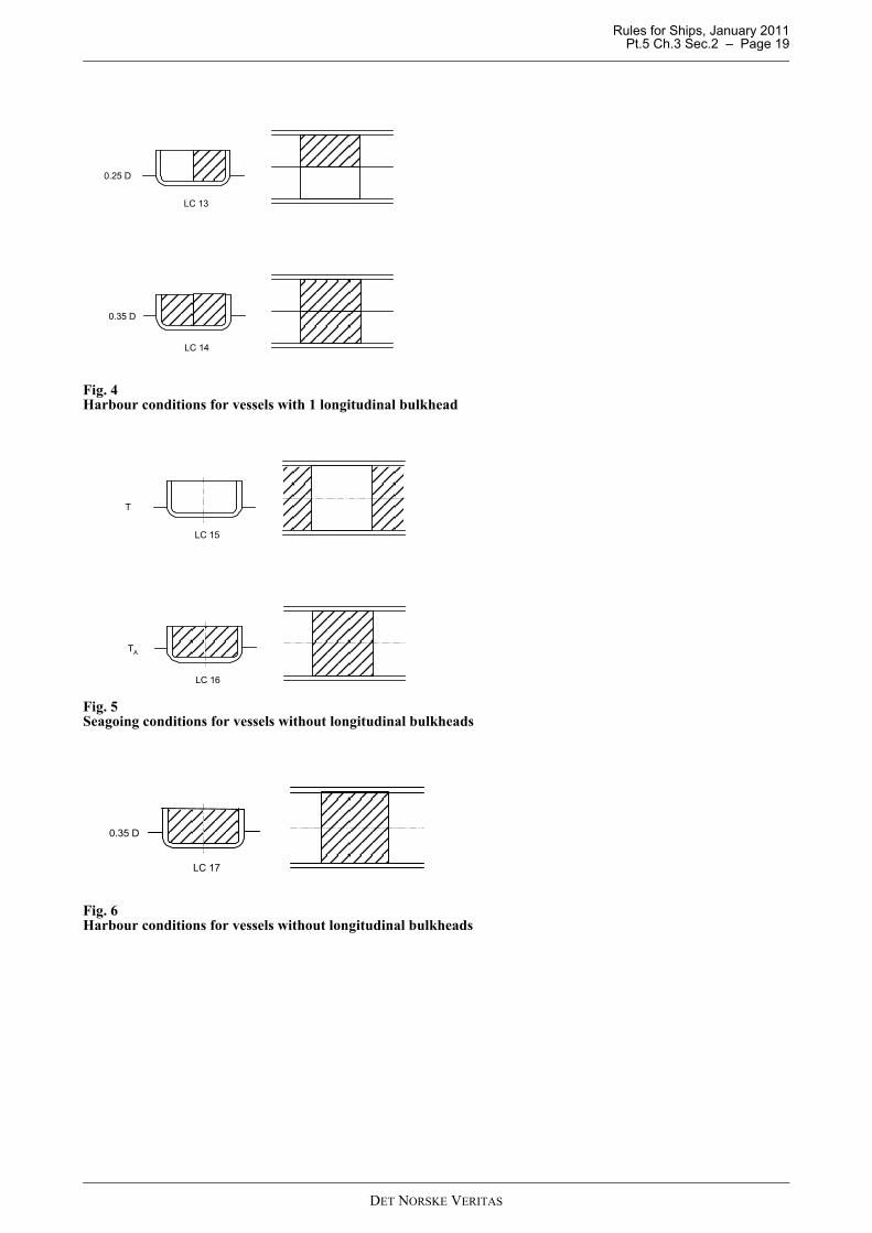
203 Load conditions following the principles below shall be examined for upright harbour conditions:
a) Any cargo tank may be filled on a draught of 0.25 D (0.35 T if this is less) with adjacent tanks empty.b) All cargo tanks in a section of the ship to be filled at a draught of 0.35 D (0.5 T if this is less) with adjoining
cargo tanks forward and aft empty.
204 The principles outlined in 202 and 203 are exemplified for different tankers as follows:For ships with 2 longitudinal bulkheads:
— seagoing conditions as given in Fig. 1— harbour conditions as given in Fig. 2.
For ships with 1 longitudinal bulkhead:
— seagoing conditions as given in Fig. 3— harbour conditions as given in Fig. 4.
For ships without longitudinal bulkheads:
— seagoing conditions as given in Fig. 5— harbour conditions as given in Fig. 6.
205 The girder structure of cargo- and ballast tanks with breadth, b > 0.6 B shall be checked for a seagoingload condition with filled tanks at a minimum draught (TA), or 0.35 D if TA is not known, and heeled to anangle of φ/2 with adjacent tanks empty. See Fig. 7. φ is as given in Sec.4 B.206 Girders on transverse bulkheads in ships with 1 or 2 longitudinal bulkheads are in addition to beconsidered for alternate loading of cargo tanks, see Fig. 8. In this condition a draught of TA to be considered.The condition is a seagoing condition.207 Ships with 2 longitudinal bulkheads and with cross ties in the centre tank shall be considered for an
Bending stresses: 160 f1 N/mm2
Shear stresses: 90 f1 N/mm2
DET NORSKE VERITAS

Rules for Ships, January 2011 Pt.5 Ch.3 Sec.2 – Page 17
asymmetric load condition with one wing tank filled and other tanks empty, unless reservations are givenagainst the practising of this condition or such condition will result in unrealistic heeling. The draught shall betaken as 0.25 D. The loading condition is a harbour condition and is illustrated in Fig. 9.208 The sloshing pressure given in Pt.3 Ch.1 Sec.4 C303 to C306 need not be taken to act simultaneouslyover the total area of any exposed tank boundary. When found necessary, relevant parts of the girder systemshall be checked.
D 300 Acceptance criteria301 Acceptance criteria shall be taken as given in Pt.3 Ch.1 Sec.12.
Fig. 1Seagoing conditions for vessels with 2 longitudinal bulkheads
T
LC 1
T
LC 2
TA
LC 3
TA
LC 4
TA
LC 5
DET NORSKE VERITAS

Rules for Ships, January 2011 Pt.5 Ch.3 Sec.2 – Page 18
Fig. 2Harbour conditions for vessels with 2 longitudinal bulkheads
Fig. 3Seagoing conditions for vessels with 1 longitudinal bulkhead
0,25 D
LC 6
LC 7
LC 8
0,25 D
0,35 D
LC 9
T
LC 10
T
LC 11
TA
LC 12
TA
DET NORSKE VERITAS
Rules for Ships, January 2011 Pt.5 Ch.3 Sec.2 – Page 19
Fig. 4Harbour conditions for vessels with 1 longitudinal bulkhead
Fig. 5Seagoing conditions for vessels without longitudinal bulkheads
Fig. 6Harbour conditions for vessels without longitudinal bulkheads
LC 13
0.25 D
LC 14
0.35 D
LC 15
T
LC 16
TA
LC 17
0.35 D
DET NORSKE VERITAS

Rules for Ships, January 2011 Pt.5 Ch.3 Sec.2 – Page 20
Fig. 7Heeled loading conditions
Fig. 8Alternate loading conditions
Fig. 9Additional load condition for vessels with cross tie in centre tank
Ø / 2
0.25 D
LC 18
DET NORSKE VERITAS

Rules for Ships, January 2011 Pt.5 Ch.3 Sec.3 – Page 21
SECTION 3 SHIP ARRANGEMENT AND STABILITY
A. Intact and Damage StabilityA 100 Intact stability101 Oil carriers of 5 000 tonnes deadweight and above shall comply with the intact stability criteria asspecified in MARPOL Annex I, Reg. 27. The requirements shall be met by design only. For combinationcarriers simple operational procedures may be allowed.
a) For ships loading and or offloading in port only, the GM corrected for free surfaces measured at 0° heelshall be not less than 0.15 m, for any operating draught under the worst possible condition of cargo andballast loading, consistent with good operational practice, including intermediate stages of liquid transferoperations.Guidance note:Ships meeting this requirement when homogeneously fully loaded at maximum draught and with the maximum freesurface effect from all cargo, ballast and consumable tanks taken into account are normally considered to comply.The unified interpretation 41 to MARPOL Annex I specifies that the vessel should be loaded with all cargo tanks filledto a level corresponding to the maximum total of vertical moment of volume plus free surface inertia moment at 0°heel for each individual tank. Cargo density should correspond to the available cargo deadweight at the displacementat which the transverse KM reaches a minimum value assuming full departure consumables and 1% of the total waterballast capacity. The maximum free surface moment should be assumed in all ballast tanks.As an alternative to the unified interpretation 41, the Society can accept detailed calculations of all possiblecombinations of cargo and ballast tank's loading as proof of compliance with the condition mentioned in a).
---e-n-d---of---G-u-i-d-a-n-c-e---n-o-t-e---
b) For ships loading and or offloading at sea, the criteria according to Pt.3 Ch.3 Sec.9 D101 shall be met forthe same conditions as in a).
c) For combination carriers, simple written supplementary operational procedures made available to themaster may be accepted which:
i) are approvedii) indicate those cargo and ballast tanks that may, under any specific condition of liquid transfer and possible
range of cargo densities, be slack and still allow the stability criteria to be met. The slack tanks may varyduring the liquid transfer operations and be of any combination provided they satisfy the criteria
iii) will be readily understandable to the officer-in-charge of liquid transfer operationsiv) allow comparisons of attained and required stability using stability performance criteria in graphical or
tabular formv) require no mathematical calculations by the officer-in-chargevi) provide for corrective actions to be taken by the officer-in charge in case of departure from
recommended values and in case of emergency situations; andvii) are prominently displayed in the approved trim and stability booklet and at the cargo and ballast transfer
control station and in any computer software by which stability calculations are performed.
A 200 Damage stability201 Oil carriers shall comply with the subdivision and damage stability requirements of MARPOL 73/78Annex I, Reg. 19 and 28.Ships of 20 000 tons deadweight and above, but less than 75 000 tons deadweight, shall survive bottom-rakingdamage extending 0.4 L measured from forward perpendicular.Ships of 75 000 tons deadweight and above shall survive bottom-raking damage extending 0.6 L measuredfrom forward perpendicular.Transverse extent: B/3 anywhere in the bottom.Vertical extent: Breach of the outer hull.202 Maximum allowable VCG curve(s), for the purpose of checking damage stability compliance, shall beincluded in the stability manual, unless one of the following alternatives are preferred:
1) The loading manual includes, in approved form, all the conditions intended to be used.2) The loading computer, intended for conditions at sea, includes approved software functions for damage
stability.
DET NORSKE VERITAS

Rules for Ships, January 2011 Pt.5 Ch.3 Sec.3 – Page 22
See Pt.6 Ch.9 Sec.1 and Sec.2.
A 300 Watertight integrity301 As far as practicable, tunnels, ducts or pipes which may cause progressive flooding in case of damage,shall be avoided in the damage penetration zone. If this is not possible, arrangements shall be made to preventprogressive flooding to volumes assumed intact. Alternatively, these volumes shall be assumed flooded in thedamage stability calculations.302 The scantlings of tunnels, ducts, pipes, doors, staircases, bulkheads and decks, forming watertightboundaries, shall be adequate to withstand pressure heights corresponding to the deepest equilibrium waterlinein damaged condition.
B. Location and Separation of SpacesB 100 General101 Machinery space shall be isolated from cargo tanks and slop tanks by cofferdams, pump rooms, oil fuelbunker tanks or ballast tanks.Spaces which may be approved as cofferdams, see F100.102 Fuel oil bunker tanks shall not be situated within the cargo area. Such tanks may, however, be situatedat forward and aft end of cargo area instead of cofferdams.However, total boundary area against cargo tanks shall not exceed 1.5 B D.Fuel oil bunker in double bottom tanks situated under cargo tanks is not permitted.103 Machinery and boiler spaces and accommodation and service spaces shall be positioned aft of the cargoarea, but not necessarily aft of fuel oil tanks.104 The lower portion of the cargo pump room may be recessed into machinery and boiler spaces toaccommodate pumps, provided the deck head of the recess is in the general not more than one-third of themoulded depth above the keel, except that in the case of ships of not more than 25 000 tons deadweight, whereit can be demonstrated that for reasons of access and satisfactory piping arrangements this is impracticable, arecess in excess of such height may be permitted, though not exceeding one half of the moulded depth abovethe keel.105 Spaces mentioned in 103 may be positioned forward of the cargo area after consideration in each case.106 Where the fitting of a navigation position above the cargo area is shown to be necessary, it shall be fornavigation purposes only, and it shall be separated from the cargo tank deck by means of an open space with aheight of at least 2 m.107 Deck spills shall be kept away from accommodation and service areas and from discharge into the seaby a permanent continuous coaming of minimum 100 mm high surrounding the cargo deck. In the aft cornersof the cargo deck the coaming must be at least 300 mm high and extend at least 4.5 m forward from each cornerand inboard from side to side. Scupper plugs of mechanical type are required. Means of draining or removingoil or oily water within the coamings shall be provided.108 Where a corner-to-corner situation occurs between a non-hazardous space and a cargo tank, a cofferdamcreated by a diagonal plate across the corner on the non-hazardous side, may be accepted as separation.Such cofferdams shall be:
— ventilated if accessible,— filled with a suitable compound if not accessible.
109 Paint lockers shall not be located within the cargo area, but may be located above oil fuel bunker tanksor ballast tanks aft of cargo tanks / slop tanks.
B 200 Arrangements of barges201 The spaces forward of the collision bulkhead (forepeak) and aft of the aftermost bulkhead (afterpeak)shall not be arranged as cargo oil tanks.
C. Tank and Pump Room ArrangementC 100 Segregated ballast tanks101 Ships of 20 000 tons deadweight and above having the class notation Tanker for Oil and ships of 30
DET NORSKE VERITAS

Rules for Ships, January 2011 Pt.5 Ch.3 Sec.3 – Page 23
000 tons deadweight and above with class notation Tanker for Oil Products shall have segregated ballasttanks. The capacity of segregated ballast tanks shall be at least such that, in any ballast condition at any part of thevoyage, including the conditions consisting of lightweight plus segregated ballast only, the ship's draughts andtrim can meet each of the following requirements:
a) The moulded draught amidships (dm) in metres (without taking into account any ship's deformation) shallnot be less than:
dm = 2.0 + 0.02 LFWhere LF is the length of the ship as defined by MARPOL.
b) the draughts at the forward and after perpendiculars shall correspond to those determined by the draughtamidships (dm) as specified in subparagraph a) of this paragraph, in association with the trim by the sternof not greater than 0.015 LF; and
c) in any case the draught at the after perpendicular shall not be less than that which is necessary to obtain fullimmersion of the propeller(s).
C 200 Protection of cargo tanks201 Ships of 600 tons deadweight but less than 5 000 tons deadweight must have a double hull arrangementcovering the entire cargo tank length with particulars as follows:
a) Double side width (m):
or w = 0.76 whichever is the greater.
DW = deadweight capacity of ship in metric tons.
b) Tankers where each cargo tank does not exceed 700 m3 may be designed with single side.Ships intended for carriage of heavy grade oil (as defined in MARPOL 73/78 Annex I, Reg. 21) as cargo,must comply with a).
c) Double bottom height (m):
or h = 0.76 whichever is the greater.
202 Ships of 5 000 tons deadweight and above must have double hull in the entire cargo tank length witharrangement as follows:
a) Double side width (m):
or w = 2.0 whichever is the lesser,
but not less than 1.0 m.
b) Double bottom height (m):
or h = 2.0 whichever is the lesser, but not less
than 1.0 m.When the distances h and w are different, the distance w shall have preference at levels exceeding 1.5 h abovethe baseline as shown in Fig. 1.
w 0.4 2.4DW20 000------------------+=
h B15------=
w 0.5 DW20 000----------------+=
h B15------=
DET NORSKE VERITAS

Rules for Ships, January 2011 Pt.5 Ch.3 Sec.3 – Page 24
Fig. 1Double hull distances
203 Double bottom tanks or spaces as required by 201 may be dispensed with, provided that the design of thetanker is such that the cargo and vapour pressure exerted on the bottom shell plating forming a single boundarybetween the cargo and the sea does not exceed the external hydrostatic water pressure, as expressed by thefollowing formula:
f hc ρc g + 100 δ p ≤ d n ρs g
hc = height of cargo in contact with the bottom shell plating in metresρc = maximum cargo density in t/m3
dn = minimum operating draught under any expected loading condition in metresρs = density of seawater in t/m3
δ p = maximum set pressure of pressure/vacuum valve provided for the cargo tank in barsf = safety factor = 1.1g = standard acceleration of gravity (9.81 m/s2).
Any horizontal partition necessary to fulfil the above requirements shall be located at a height of not less thanB/6 or 6 m, whichever is the lesser, but not more than 0.6 D, above the baseline where D is the moulded depthamidships.The location of wing tanks or spaces shall be as defined in 202 except that below a level 1.5 h above the baselinewhere h is as defined in 202 the cargo tank boundary line may be vertical down to the bottom plating.204 Suction wells in cargo tanks may protrude into the double bottom below the boundary line defined bythe distance h provided that such wells are as small as practicable and the distance between the well bottom andbottom shell plating is not less than 0.5 h.
Guidance note:For combined oil and chemical tankers, the requirements for the suction well in Pt.5 Ch.4 Sec.3 B104 are stricter.
---e-n-d---of---G-u-i-d-a-n-c-e---n-o-t-e---
C 300 Cargo tanks and slop tanks301 Hypothetical outflow of oil in the case of side damage and bottom damage shall be within the limitsrequired in MARPOL 73/78 Annex I, Reg. 25.302 Limitation of size and arrangement of cargo tanks shall comply with the provisions of MARPOL 73/78Annex I, Reg. 26.303 Oil carriers of 150 gross tonnage and above shall be provided with arrangements of slop tank orcombination of slop tanks with a total capacity complying with MARPOL 73/78 Annex I, Reg. 29.304 Oil carriers of 70 000 tons deadweight and above shall be provided with at least two slop tanks.305 Slop tanks shall be designed particularly with respect to decantation purpose. Positions of inlets, outlets,baffles or weirs where fitted, shall be placed so as to avoid excessive turbulence and entrainment of oil oremulsion with the water.
h > w
hh
hh
h < w
1.5 h
base line
w
w
w
w
DET NORSKE VERITAS
Rules for Ships, January 2011 Pt.5 Ch.3 Sec.3 – Page 25
C 400 Double bottom in pump rooms401 Pump rooms in ships of 5 000 tons deadweight and above, must be provided with a double bottom withdepth h as follows:
(m) or
h = 2.0 m, whichever is lesser, but not less than 1.0 m.
D. Arrangement of Access and Openings to Spaces and Tanks
D 100 Accommodation and non-hazardous spaces101 Entrances, air inlets and openings to accommodation spaces, service spaces, control stations andmachinery spaces shall not face the cargo area. They shall be located on the end bulkhead and or on theoutboard side of the superstructure or deckhouse at a distance of at least L/25 but not less than 3 m from theend of the superstructure or deckhouse facing the cargo area. This distance, however, need not exceed 5 m.Within the limits specified above, the following apply:
a) Bolted plates for removal of machinery may be fitted. Such plates shall be insulated to A-60 class standard.Signboards giving instruction that the plates shall be kept closed unless the ship is gas-free, shall be postedon board.
b) Wheelhouse windows may be non-fixed and wheelhouse doors may be located within the above limits aslong as they are so designed that a rapid and efficient gas and vapour tightening of the wheelhouse can beensured.
c) Windows and side scuttles shall be of the fixed (non-opening) type. Such windows and side scuttles exceptwheelhouse windows, shall be constructed to A-60 class standard.
102 Cargo control rooms, stores and other spaces not covered by 103 but located within accommodation,service and control stations spaces, may be permitted to have doors facing the cargo area. Where such doorsare fitted, the spaces are not to have access to the spaces covered by 103 and the boundaries of the spaces areto be insulated to A-60 class.103 For access and openings to non-hazardous spaces other than accommodation and service spaces, thefollowing provisions apply:
— entrances shall not be arranged from hazardous spaces— entrances from hazardous areas on open deck are normally not to be arranged. If air locks are arranged such
entrances may, however, be approved, see 105 and 106— entrances to non-hazardous forecastle spaces from hazardous areas shall be arranged with air locks, see
104.
104 Ventilation inlets for the spaces mentioned in 101 are to be located as far as practicable from gas-dangerous zones, and in no case are the ventilation inlets nor outlets to be located closer to the cargo area thanspecified for doors in 101.105 Entrance through air locks to non-hazardous spaces shall be arranged at a horizontal distance of at least3 m from any opening to a cargo tank or hazardous space containing gas sources, such as valves, hoseconnections or pumps used with the cargo.106 Air locks shall comply with the following requirements:
a) Air locks shall be enclosed by gastight steel bulkheads with two substantially gas tight self-closing doorsspaced at least 1.5 m and not more than 2.5 m apart. The door sill height shall comply with the requirementgiven in Pt.3 Ch.3 Sec.6 B, but shall not be less than 300 mm.
b) Air locks shall have a simple geometrical form. They shall provide free and easy passage, and shall have adeck area not less than about 1.5 m2. Air locks shall not be used for other purposes, for instance as storerooms.
c) An alarm (acoustic and visual) shall be released on both sides of the air lock to indicate if more than onedoor have been moved from the fully closed position.
d) Air locks shall have effective ventilation. For requirements for ventilation, see Sec.6.
D 200 Access to and within hazardous spaces201 Access to and within spaces in, and forward of, the cargo area shall comply with SOLAS Regulation II-1/3-6.
h B15------=
DET NORSKE VERITAS

Rules for Ships, January 2011 Pt.5 Ch.3 Sec.3 – Page 26
202 Doors to hazardous spaces, situated completely upon the open deck, shall have as low a sill height aspossible. Such compartments shall not be connected with compartments at a lower level.203 For deck openings for scaffolding wire connections, the number and position of holes in the deck aresubject to approval.The closing of the holes may be effected by screwed plugs of metal or an acceptable synthetic material, seeSec.4 A.The material used in the manufacture of plugs and jointing, if any, shall be impervious to all cargoes intendedto be carried.Metal plugs shall have a fine screw thread to ensure an adequate number of engaging threads.A number of spare plugs equal to at least 10% of the total number of holes shall be kept on board.
E. Guard Rails and Bulwarks E 100 Arrangement101 On tank deck open guard rails are normally to be fitted. Plate bulwarks, with a 230 mm high continuousopening at lower edge, may be accepted upon consideration of the deck arrangement and probable gasaccumulation.
F. Cofferdams and Pipe TunnelsF 100 Cofferdams101 Cofferdams shall be of sufficient size for easy access to all parts, and they shall cover the entire adjacenttank bulkhead.Minimum distance between bulkheads: 600 mm.102 Pump rooms and ballast tanks will be accepted as cofferdams. Ballast tanks will, however, not beaccepted as cofferdams for protected slop tanks. See Sec.12.
F 200 Pipe tunnels201 Pipe tunnels shall have ample space for inspection of the pipes.202 The pipes in pipe tunnels shall be situated as high as possible above the ship's bottom.There shall be no connection between a pipe tunnel and the engine room neither by pipes nor manholes.203 Provision shall be made for at least two exits to the open deck arranged at a maximum distance from eachother. One of these exists fitted with a watertight closure may lead to the cargo pump room.204 Where there is permanent access from a pipe tunnel to the main pump-room, a watertight door shall befitted complying with the requirements of SOLAS Ch. II-1/25-9, and in addition with the followingrequirements:
a) In addition to bridge operation, the watertight door shall be capable of being manually closed from outsidethe main pump-room entrance.
b) The watertight door shall be kept closed during normal operations of the ship except when access to thepipe tunnel is required.
G. Diesel Engines for Emergency Fire PumpsG 100 General101 Diesel engines for emergency fire pump, shall be installed in a non hazardous space.102 The exhaust pipe of the diesel engine, if fitted forward of the cargo area, shall have an effective sparkarrester, and shall be led out to the atmosphere outside hazardous areas.
DET NORSKE VERITAS
Rules for Ships, January 2011 Pt.5 Ch.3 Sec.3 – Page 27
H. Chain Locker and Anchor Windlass H 100 General101 The chain locker shall be arranged as a non hazardous space.102 Windlass cable lifters and chain pipes shall be situated outside hazardous areas.
I. Equipment in Tanks and CofferdamsI 100 General101 Anodes, washing machines and other permanently attached equipment units in tanks and cofferdamsshall be securely fastened to the structure. The units and their supports shall be able to withstand sloshing inthe tanks and vibratory loads as well as other loads which may be imposed in service.
Guidance note:When selecting construction materials in permanently attached equipment units in tanks and cofferdams, dueconsideration should to be paid to the contact spark-producing properties.
---e-n-d---of---G-u-i-d-a-n-c-e---n-o-t-e---
J. Surface Metal Temperatures in Hazardous AreasJ 100 General101 Surface metal temperatures of equipment and piping in hazardous areas shall not exceed 220°C.
DET NORSKE VERITAS

Rules for Ships, January 2011 Pt.5 Ch.3 Sec.4 – Page 28
SECTION 4 PIPING SYSTEMS IN CARGO AREA
A. Piping MaterialsA 100 Selection and testing101 Materials are generally to be selected according requirements given in Pt.4 Ch.6 for piping materials. Theselected materials shall be tested according to regulations in Pt.2.102 Other materials may be accepted after special consideration.103 Synthetic materials for components and piping shall be approved in each separate case.
A 200 Special requirements for cargo piping system201 Valves and distance pieces or reducers outboard of valves, which are connected directly to the cargopipeline's shore connection on deck, shall be made of steel.
A 300 Plastic pipes in cargo area301 Plastic pipes of approved type and tested according to an approved specification may be accepted. Forthe application of plastic pipes, see Pt.4 Ch.6.302 When used in a hazardous area, the surface resistance per unit length of pipes shall not exceed 105 Ω/mand the resistance to earth from any point in the piping system shall not exceed 106 Ω.
A 400 Aluminium coatings401 Aluminised pipes are generally accepted in non-hazardous areas and may be permitted in hazardousareas on open deck and in inerted cargo tanks and ballast tanks.Restrictions on use of aluminium paints, see Pt.3 Ch.3 Sec.7.
B. Bilge, Ballast and Fuel Oil Systems B 100 General101 There shall be no connection between piping systems in the cargo area and piping systems in theremainder of the ship, unless explicitly specified in this section.
B 200 Drainage of pump rooms, cofferdams, pipe tunnels, ballast and fuel oil tanks201 Cargo pump rooms shall have a drainage system connected to pumps or bilge ejectors.202 Cargo pumps may be used for bilge service provided each bilge suction pipe is fitted with a screw-downnon-return valve, and an additional stop valve is fitted to the pipe connection between pump and the non-returnvalve.203 The bilge pipes in the cargo pump room shall not be led into the engine room.204 Cofferdams and pipe tunnels shall be provided with bilge suctions.205 The forward cofferdam may be drained with pumps situated forward of the cofferdam.206 The after cofferdam not forming a part of the cargo pump room may be drained by a direct suction to thebilge system in the engine room.207 Pipe tunnels shall be drained from the cargo pump room or an equivalent hazardous space.208 Segregated ballast tanks within the cargo area shall be served by ballast pumps in the cargo pump room,in a similar hazardous space or inside ballast tanks. Ballast tanks shall be provided with at least two drainpumping units. At least one of the pumps shall be exclusively used for ballast. As another means an eductor oran emergency connection to a cargo pump may be accepted. Segregated ballast systems shall not have anyconnections to the cargo system, but an emergency discharge of ballast water may be arranged by connectionto a cargo pump.The connection pipe shall be provided with a removable spool piece and a closing valve and non-return valvein series in the suction side to the cargo oil pump.209 Arrangements for discharge of water ballast and oil contaminated water from the cargo area shall bemade above the waterline in the deepest ballast condition, in accordance with MARPOL 73/78 Annex I,Reg.30.
DET NORSKE VERITAS
Rules for Ships, January 2011 Pt.5 Ch.3 Sec.4 – Page 29
210 A discharge manifold for connection to reception facilities for the discharge of dirty ballast water or oilcontaminated water shall be located on the open deck on both sides of the ship.211 For ships arranged with emergency connection between the cargo system and the segregated ballastsystem as specified in 208, the discharge manifold required by 210 may be omitted.212 Ballast tanks forward of cargo area may be connected to the ballast pumps in the aft cargo pump room,see 213.213 Ballast piping and other piping such as sounding and vent piping to ballast tanks shall not pass throughcargo tanks.214 Drainage of ballast tanks, see Pt.4 Ch.6 Sec.4 I.215 Fuel oil bunker tanks adjacent to cargo tanks may be connected directly to pumps in the engine room.The pipes shall not pass through cargo tanks and shall have no connection with pipelines serving such tanks.
B 300 Fore peak ballast tank301 The fore peak may be ballasted with the system serving ballast tanks within the cargo area, provided:
a) The fore peak tank is considered as hazardous.b) The vent pipe openings are located on open deck 3 m away from sources of ignition.c) Means are provided, on the open deck, to allow measurement of flammable gas concentrations within the
tank by a suitable portable instrument.d) The access to the fore peak and the sounding arrangements are directly from open deck. In case the fore
peak tank is separated by cofferdams from the cargo tanks, an access through a gas tight bolted manholelocated in an enclosed space may be accepted. In that case, a warning sign shall be provided at the manholestating that the tank may only be opened after it has been proven to be gas free or the electrical equipmentwhich is not certified safe in the enclosed space, is isolated.
B 400 Oil discharge monitoring and control systems401 Oil carriers of 150 gross tonnage and above shall be equipped with an approved arrangement for oilcontent monitoring of oily ballast and tank washing water in accordance with MARPOL 73/78 Annex I, Reg.31. The system shall record continuously the discharge of oil in litres per nautical mile and total quantity of oildischarged, or the oil content and rate of discharge.402 An instruction and operation manual describing all essential procedures for manual and automaticoperations shall be worked out and submitted for approval.
Guidance note:Reference is made to IMO MEPC.108(49) - Revised Guidelines and Specifications for Oil Discharge Monitoring andControl Systems for Oil Tankers.
---e-n-d---of---G-u-i-d-a-n-c-e---n-o-t-e---
403 Oil tankers of 150 gross tonnage and above, shall be provided with an effective oil and water interfacedetector of approved type in accordance with MARPOL 73/78 Annex I, Reg. 32, for determination of the oilwater inter face in slop tanks and other tanks where separation of oil and water is effected and from which it isintended to discharge effluent direct to sea.
B 500 Oil Record Book and SOPEP501 Oil carriers of 150 gross tonnage and above shall be provided with an Oil Record Book in accordancewith MARPOL 73/78 Annex I, Reg. 36.502 Oil carriers of 150 gross tonnage and above shall be provided with a Shipboard Oil Pollution EmergencyPlan (SOPEP) approved by an Administration in accordance with MARPOL 73/78 Annex I, Reg. 37.
B 600 Air, sounding and filling pipes 601 Filling of tanks within cargo area shall be carried out from the cargo pump room or a similar hazardousspace.602 Filling lines to permanent ballast tanks and other discharge lines to cargo area may be connected topumps outside the cargo area (e.g. engine room), provided the lines are not carried through cargo tanks andadjacent spaces and do not have a permanent connection to any cargo tank.The arrangement is subject to approval in each separate case.603 Filling lines to permanent ballast tanks shall be so arranged that the generation of static electricity isreduced, e.g. by reducing the free fall into the tank to a minimum.
DET NORSKE VERITAS

Rules for Ships, January 2011 Pt.5 Ch.3 Sec.4 – Page 30
604 Suction for seawater to permanent ballast tanks shall not be arranged in the same sea chest as used fordischarge of ballast water from cargo tanks, see also C208.
Guidance note:Seawater suction should be arranged at the opposite side from the discharge of ballast water from cargo tanks.
---e-n-d---of---G-u-i-d-a-n-c-e---n-o-t-e---
605 Cofferdams shall be provided with sounding pipes and with air pipes led to the atmosphere. The air pipesshall be fitted with flame screens at their outlets.
C. Cargo SystemsC 100 General101 A permanent system of piping and pumps shall be provided for the cargo tanks.This system shall be entirely separate from all other piping systems on board.Exemption, see Sec.5 A.102 At least two independently driven cargo oil pumps shall be connected to the system.103 In tankers where cargo tanks are equipped with independent pumps (e.g. deep well pumps), theinstallation of one pump per tank may be approved. Satisfactory facilities shall be provided for emptying thetanks in case of failure of the regular pump.104 Hydraulically powered pumps, submerged in cargo tanks (e.g. deep well pumps), shall be arranged withdouble barriers, preventing the hydraulic system serving the pumps from being directly exposed to the cargo.The double barrier shall be arranged for detection and drainage of possible cargo leakages.105 Materials, see A.106 The wall thickness of cargo pipes will be specially considered on the basis of anticipated corrosion. Thethickness of the pipes are, however, not to be less than given in Pt.4 Ch.6 Sec.6 A.107 All cargo piping shall be electrically bonded to the ship's hull. The resistance to earth from any point inthe piping system is not to exceed 106 Ω. Fix points may be considered as an effective bonding.Piping sections not permanently connected to the hull, shall be electrically bonded to the hull by bonding straps.
C 200 Piping systems201 The complete cargo piping system shall be located within the cargo area.202 Valves or branch pieces, which connect the cargo pipeline's shore connection on deck, and cargo pipingshall be supported with due regard to load stresses.203 Expansion elements shall be provided in the cargo piping as necessary.204 Means for drainage of the cargo lines shall be provided. Tankers for oil (Tanker for Oil) of 20 000 tonsdeadweight and above, and tankers for oil products (Tanker for Oil Products) of 30 000 tons deadweightand above, shall be provided with a special small diameter line, not exceeding 10% of the cross-sectional areaof main cargo line, for discharge ashore. This line shall be connected outboard of the ship's manifold valves.Stripping systems for ships provided with deep well cargo pumps shall be specially considered.205 The cargo piping system shall not have any connection to permanent ballast tanks.206 Cargo piping and similar piping to cargo tanks shall not pass through ballast tanks. Exemptions to thisrequirement may be granted for short length of pipes with heavy wall thickness, provided that they arecompletely welded.
Guidance note:Short length of pipes may be such as through stool tanks used for ballast etc.
---e-n-d---of---G-u-i-d-a-n-c-e---n-o-t-e---
207 Filling lines to cargo tanks shall be so arranged that the generation of static electricity is reduced, e.g. byreducing the free fall into the tank to a minimum.208 The discharge of ballast water from cargo tanks shall be arranged in such a way as to prevent the ballastwater from being drawn into sea suctions for other pipe systems, i.e. cooling water systems for machinery.209 Isolation of cargo piping connections to sea shall be made by means of at least two shut-off valves.
DET NORSKE VERITAS
Rules for Ships, January 2011 Pt.5 Ch.3 Sec.4 – Page 31
Arrangement for tightness monitoring of sea valves shall be provided.Guidance note:
— For tankers delivered on or after 2010-01-01, MARPOL 73/78 Annex I, Reg. 30.7 will apply for this arrangement.— For arrangement of tightness testing of sea valves, see OCIMF's recommendations “Prevention of oil spillages
through cargo pump room sea valves”.
---e-n-d---of---G-u-i-d-a-n-c-e---n-o-t-e---
210 Where pumps in cargo room or other hazardous spaces are driven by shafting passing into the pump roomthrough bulkheads or deck plating, gastight glands of approved type shall be fitted. The glands shall beefficiently lubricated and constructed so as to reduce the risk of overheating. The glands shall be visible andeasily accessible.Parts which may accidentally come into contact if the seal is badly aligned or if a bearing is damaged, shall beof such materials that no spark may occur. If an expansion bellow is fitted, it shall be hydraulically pressuretested.211 Displacement pumps shall have relief valves with discharge to the suction line.212 For systems served by centrifugal pumps the design pressure for the piping shall be at least equal to thehighest pressure the pump may generate. Alternatively a pressure relief valve or alternative means forautomatically safeguarding against overpressure shall be provided.213 Means shall be provided for stopping the cargo pumps at the cargo manifolds and at the lower pumproom level.214 Remote control and monitoring of the cargo handling, see Sec.9.215 All ships having a Noxious Liquid Substances (NLS) Certificate for the carriage of liquid substances aslisted in the IBC Code Chapter 18 Category Z, are to have on board a Cargo Record Book according toMARPOL 73/78 Annex II, Appendix 2.
C 300 Cargo piping systems for barges301 The barge shall be equipped with a permanent piping system for the oil cargo.Closing valves operable from outside the tank shall be fitted to each branch pipe within the tank it serves.302 At least two independently driven cargo pumps shall be connected to the cargo piping system.If each cargo tank is fitted with a separate cargo pump, one cargo pump per tank may be accepted.303 For unmanned barges without auxiliary machinery, non-permanent cargo pumps with external powersupply may be acceptable.The pumps shall be connected to the piping system on open deck or in a cargo pump room.304 Cargo pump room situated below deck shall have a power operated bilge system.Cargo pump room may have bilge suctions to the cargo pumps.
C 400 Testing401 Cargo piping shall be hydrostatically tested in the presence of the surveyor to a test pressure = 1.5 × themaximum working pressure.If hydrostatic testing of separate lengths of piping valves, expansion elements etc. has been carried out prior tothe installation on board, a tightness test to at least the design pressure is required after completion of theinstallation onboard.
D. Cargo HeatingD 100 General101 The heating media shall be compatible with the cargo and the temperature of the heating medium isnormally not to exceed 220°C.
D 200 Steam heating201 Water systems and steam systems shall comply with Pt.4 Ch.6 unless otherwise stated.202 Where steam and exhaust pipes for heating coils are fitted in the cargo tanks, it shall be possible to blankflange the steam and exhaust pipes outside the engine or boiler room.203 Condensate from cargo heating systems shall be led into an observation tank placed in an easily
DET NORSKE VERITAS

Rules for Ships, January 2011 Pt.5 Ch.3 Sec.4 – Page 32
accessible, well ventilated and well illuminated position where it can easily be observed whether thecondensate is free from oil or not. The scum pipes shall be led to a waste oil tank. If the condensate shall beused as feed water for boilers, an effective oil filtering system shall be arranged.
D 300 Thermal oil heating301 Requirements to thermal-oil installations are given in Pt.4 Ch.7 Sec.3 B.302 Heating of liquid cargoes with flash point not exceeding 60°C shall be arranged by means of a separatesecondary system located in the cargo area. However, a single circuit system may be accepted on the followingconditions:
— system is so arranged that a positive pressure in the coil shall be at least 3 m water column above the statichead of the cargo when circulating pump is not in operation
— the thermal oil system expansion tank shall be fitted with high and low level alarms— means shall be provided in the thermal oil system expansion tank for detection of flammable cargo vapours— valves for the individual heating coils shall be provided with locking arrangement to ensure that the coils
are under static pressure at all times.
D 400 Heating of cargo with temperatures above 120°C 401 Heating plants for asphalt tanks shall be arranged with redundancy.402 Heating coils in asphalt tanks shall be separated into at least two independent systems.403 Heating system for cargo pumps and cargo lines to be arranged.404 Temperature gauges shall be arranged in each cargo tanks enabling the recording of temperatures atbottom, midway between bottom and deck and at deck level in order to prevent overheating of cargo.405 For requirements for NDT of heating coils, see Pt.4 Ch.6 Sec.7 A500.
E. Bow and Stern Loading and Unloading ArrangementsE 100 General101 Subject to the approval of the society, cargo piping may be fitted to permit bow and stern loading andunloading.
E 200 Piping arrangement201 In addition to Pt.4 Ch.6 Sec.6, the following provisions apply:
a) Bow and stern loading and unloading pipes shall be led outside accommodation spaces, service andmachinery spaces within the accommodation or control stations.
b) Cargo lines forward or aft of the cargo area, except at the loading station shall have welded connections.Such piping shall be clearly identified and fitted with two valves or one valve and a spool piece or blanksat its connection to the cargo piping system within the cargo area.
c) The shore connection shall be fitted with a shut-off valve and a blank flange.d) Spray shields shall be provided at the connections specified in c).e) The piping shall be self-draining to the cargo area, preferably into a cargo tank.f) Arrangements shall be made to allow for purging and gasfreeing of the piping to the cargo area. g) Entrances, air inlets and openings to accommodation, service and machinery spaces and control stations
shall comply with SOLAS Reg. II-2/4.5.1.6 to 4.5.2.3.h) A fixed foam fire-extinguishing system covering loading and unloading areas shall be provided.i) Loading and unloading arrangements shall not interfere with safety equipment.j) Continuous coamings shall be fitted to keep any spills away from accommodation and service areas.
Regarding additional class notations BOW LOADING or STL for offshore loading operations, see Sec.14.
DET NORSKE VERITAS
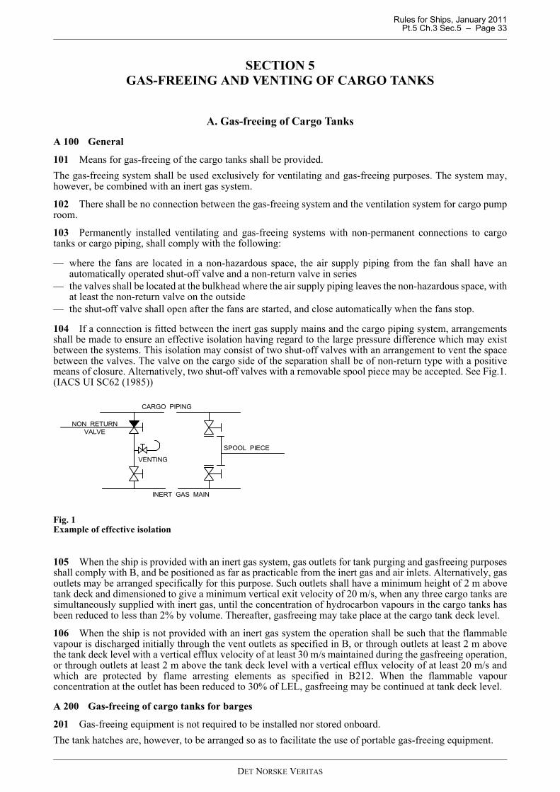
Rules for Ships, January 2011 Pt.5 Ch.3 Sec.5 – Page 33
SECTION 5 GAS-FREEING AND VENTING OF CARGO TANKS
A. Gas-freeing of Cargo Tanks
A 100 General
101 Means for gas-freeing of the cargo tanks shall be provided.The gas-freeing system shall be used exclusively for ventilating and gas-freeing purposes. The system may,however, be combined with an inert gas system.
102 There shall be no connection between the gas-freeing system and the ventilation system for cargo pumproom.
103 Permanently installed ventilating and gas-freeing systems with non-permanent connections to cargotanks or cargo piping, shall comply with the following:
— where the fans are located in a non-hazardous space, the air supply piping from the fan shall have anautomatically operated shut-off valve and a non-return valve in series
— the valves shall be located at the bulkhead where the air supply piping leaves the non-hazardous space, withat least the non-return valve on the outside
— the shut-off valve shall open after the fans are started, and close automatically when the fans stop.
104 If a connection is fitted between the inert gas supply mains and the cargo piping system, arrangementsshall be made to ensure an effective isolation having regard to the large pressure difference which may existbetween the systems. This isolation may consist of two shut-off valves with an arrangement to vent the spacebetween the valves. The valve on the cargo side of the separation shall be of non-return type with a positivemeans of closure. Alternatively, two shut-off valves with a removable spool piece may be accepted. See Fig.1.(IACS UI SC62 (1985))
Fig. 1Example of effective isolation
105 When the ship is provided with an inert gas system, gas outlets for tank purging and gasfreeing purposesshall comply with B, and be positioned as far as practicable from the inert gas and air inlets. Alternatively, gasoutlets may be arranged specifically for this purpose. Such outlets shall have a minimum height of 2 m abovetank deck and dimensioned to give a minimum vertical exit velocity of 20 m/s, when any three cargo tanks aresimultaneously supplied with inert gas, until the concentration of hydrocarbon vapours in the cargo tanks hasbeen reduced to less than 2% by volume. Thereafter, gasfreeing may take place at the cargo tank deck level.
106 When the ship is not provided with an inert gas system the operation shall be such that the flammablevapour is discharged initially through the vent outlets as specified in B, or through outlets at least 2 m abovethe tank deck level with a vertical efflux velocity of at least 30 m/s maintained during the gasfreeing operation,or through outlets at least 2 m above the tank deck level with a vertical efflux velocity of at least 20 m/s andwhich are protected by flame arresting elements as specified in B212. When the flammable vapourconcentration at the outlet has been reduced to 30% of LEL, gasfreeing may be continued at tank deck level.
A 200 Gas-freeing of cargo tanks for barges
201 Gas-freeing equipment is not required to be installed nor stored onboard.The tank hatches are, however, to be arranged so as to facilitate the use of portable gas-freeing equipment.
SPOOL PIECE
INERT GAS MAIN
VENTING
NON RETURNVALVE
CARGO PIPING
DET NORSKE VERITAS
Rules for Ships, January 2011 Pt.5 Ch.3 Sec.5 – Page 34
B. Cargo Tank Venting SystemsB 100 General101 All cargo tanks shall have a breathing system for relief of pressure and vacuum. Such breathing shall bethrough P/V valves, (pressure or vacuum relief valves).102 All cargo tanks shall have a venting system for avoiding excessive overpressure or vacuum duringloading and unloading with closed tank hatch covers.The system shall be designed with redundancy for the relief of full flow overpressure and vacuum. Pressuresensors fitted in each cargo tank, and connected to an alarm system, may be accepted in lieu of the redundancyrequirement for pressure relief.See Sec.9 regarding high level alarms, overflow systems etc.
B 200 System design201 The breathing and venting systems may be independent or combined and may be connected to an inertgas system. Pipes for breathing and venting shall be led from each tank’s highest point and shall be self-draining to the cargo tanks under all normal conditions of trim and list.202 Separate system (e.g. stand pipe) for each tank or connection of tanks to a common main pipe may beapproved. When connection to a common main pipe is arranged, each branch pipe shall be fitted with meansof isolation. If the tank is not fitted with a separate P/V valve, the means of isolation shall be constructed insuch a way that tank breathing is maintained when the branch pipe is isolated.203 Shut-off valves shall not be fitted neither above nor below P/V valves, but by-pass valves may beprovided.204 The opening pressure of the pressure relief valves shall be less than the design vapour pressure for thecargo tanks. The opening pressure of the vacuum relief valves is normally not to be lower than 0.07 bar belowatmospheric pressure.205 P/V valves shall be located on open deck and shall be of a type which allows the functioning of the valveto be easily checked.206 Venting systems to be used for cargoes (e.g. asphalt) that may cause clogging of the venting lines, willbe specially considered.207 Intake openings of vacuum relief valves shall be located at least 1.5 m above tank deck, and shall beprotected against the sea. The arrangement shall comply with the requirements in Pt.3 Ch.3 Sec.6.208 Gas outlets for thermal breathing only (small capacity P/V valves) shall be located at a minimum heightof 2 m above tank deck or gangway, if situated within 4 m of the gangway, and at a distance of not less than 5m from air intakes and openings to enclosed spaces containing a source of ignition, and from equipment whichmay constitute an ignition hazard.209 When the venting system during loading and unloading is by free flow of vapour mixtures, the outletsshall be not less than 6 m above the tank deck or gangway, if situated within 4 m of the gangway, and locatednot less than 10 m measured horizontally from air intakes and openings to enclosed spaces containing a sourceof ignition, and from equipment which may constitute an ignition hazard.210 When the venting system during loading and unloading is by high velocity discharge the height of thegas outlets shall be located at a minimum height of 2 m above tank deck or gangway, if situated within 4 m ofthe gangway, and located not less than 10 m measured horizontally from air intakes and openings to enclosedspaces containing a source of ignition, and from equipment which may constitute an ignition hazard. Highvelocity devices shall be of an approved type.211 Gas outlets used during loading shall be directed vertically upwards.212 Gas outlets and air inlets for cargo tanks shall have flame arresting elements tested and approvedaccording to IMO MSC/Circ.677 as amended by MSC/Circ.1009.213 The flow area of the venting system used during loading shall be based upon not less than 125% of thegas volume flow corresponding to the maximum anticipated loading rate.214 In pipe systems for escape gas, after P/V valves, means for draining shall be fitted where condensate mayaccumulate.
B 300 Venting of cargo tanks for barges301 The cargo tanks shall be provided with a venting system to facilitate loading and unloading with closedtank hatches without imposing excessive overpressure or vacuum on the tanks.302 Breathing system with P/V valves will normally not be required.
DET NORSKE VERITAS

Rules for Ships, January 2011 Pt.5 Ch.3 Sec.6 – Page 35
SECTION 6 VENTILATION SYSTEMS WITHIN THE CARGO AREA
OUTSIDE THE CARGO TANKS
A. Ventilation SystemsA 100 General 101 Any ducting used for the ventilation of hazardous spaces shall be separate from that used for theventilation of non-hazardous spaces. Ventilation systems within the cargo area shall be independent of other ventilation systems.102 Air inlets for hazardous enclosed spaces shall be taken from areas which, in the absence of the consideredinlet, would be non-hazardous.Air inlets for non-hazardous enclosed spaces shall be taken from non-hazardous areas at least 1.5 m from theboundaries of any hazardous area.Where the inlet duct passes through a more hazardous space, the duct shall have over-pressure relative to thisspace, unless mechanical integrity and gas-tightness of the duct will ensure that gases will not leak into it.103 Air outlets from non-hazardous spaces shall be located outside hazardous areas.104 Air outlets from hazardous enclosed spaces shall be located in an open area which, in the absence of theconsidered outlet, would be of the same or lesser hazard than the ventilated space.105 Ventilation ducts for spaces within the cargo area are not to be led through non-hazardous spaces.106 Non-hazardous enclosed spaces shall be arranged with ventilation of the overpressure type. Hazardousspaces shall have ventilation with under-pressure relative to the adjacent less hazardous spaces.107 Starters for fans for ventilation of gas-safe spaces within the cargo area shall be located outside this area oron open deck.If electric motors are installed in such spaces, the ventilation capacity shall be large enough to prevent thetemperature limits specified in Pt.4 Ch.8 from being exceeded, taking into account the heat generated by theelectric motors.108 Wire mesh protection screens of not more than 13 mm square mesh shall be fitted in outside openings ofventilation ducts.For ducts where fans are installed, protection screens are also to be fitted inside of the fan to prevent theentrance of objects into the fan housing109 Spare parts for fans shall be carried onboard. Normally wear parts for one motor and one impeller isrequired for each type of fan serving spaces in the cargo area.
A 200 Fans serving hazardous spaces201 Electric fan motors shall not be installed in ventilation ducts for hazardous spaces unless the motor iscertified for the same hazard zone as the space served.202 Fans shall be designed with the least possible risk for spark generation.203 Minimum safety clearances between the casing and rotating parts shall be such as to prevent any frictionwith each other.In no case is the radial air gap between the impeller and the casing to be less than 0.1 of the diameter of theimpeller shaft in way of the bearing, but not less than 2 mm.It need not be more than 13 mm.204 The parts of the rotating body and of the casing shall be made of materials which are recognised as beingspark proof, and they shall have antistatic properties.Furthermore, the installation on board of the ventilation units shall be such as to ensure the safe bonding to thehull of the units themselves. Resistance between any point on the surface of the unit and the hull, shall not begreater than 106 Ohm.The following combinations of materials and clearances used in way of the impeller and duct are considered tobe none-sparking:
— impellers and/or housing of non-metallic material, due regard being paid to the elimination of staticelectricity
— impellers and housings of non-ferrous metals
DET NORSKE VERITAS
Rules for Ships, January 2011 Pt.5 Ch.3 Sec.6 – Page 36
— impellers of aluminium alloys or magnesium alloys and a ferrous (including austenitic stainless steel)housing on which a ring of suitable thickness of non- ferrous materials is fitted in way of the impeller, dueregard being paid to static electricity and corrosion between ring and housing
— impellers and housing of austenitic stainless steel— any combination of ferrous (including austenitic stainless steel) impellers and housing with not less than
13 mm tip design clearance.
205 Any combination of an aluminium or magnesium alloy fixed or rotating component, and a ferrous fixedor rotating component, regardless of tip clearance, is considered a spark hazard and shall not be used in theseplaces.
B. Ventilation Arrangement and Capacity Requirements
B 100 General101 The required capacity of the ventilation plant is normally based on the total volume of the room. Anincrease in required ventilation capacity may be necessary for rooms with a complicated shape.
B 200 Non-hazardous spaces201 Spaces with opening to a hazardous area, shall be arranged with an air-lock, and be maintained atoverpressure, relative to the external hazardous area. The overpressure ventilation shall be arranged according to the following requirements:
1) During initial start-up or after loss of overpressure ventilation, it is required before energising any electricalinstallations not certified safe for the space in the absence of pressurisation, to:
— proceed with purging (at least 5 air changes) or confirm by measurements that the space is non-hazardous, and
— pressurise the space.
2) Operation of the overpressure ventilation shall be monitored.3) In the event of failure of the overpressure ventilation:
— an audible and visual alarm shall be given at a manned location— if overpressure cannot be immediately restored, automatic or programmed disconnection of electrical
installations is required according to IEC 60092-502, Table 5.
B 300 Cargo handling spaces 301 A permanent mechanical ventilation system of the extraction type shall be installed, capable ofcirculating sufficient air to give at least 20 air changes per hour.In the cargo pump room, exhaust trunking shall be arranged as follows:
— in the cargo pump room bilges just above the transverse floor plates or bottom longitudinals, so that air canflow over the top from adjacent spaces.
302 The electrical lighting in the cargo pump room shall be fitted with an interlock so arranged that theventilation must be in operation before the electrical supply to the lighting in the room can be connected.Emergency lighting shall not be interlocked. Failure of the ventilation system shall not cause the lighting to goout.303 The exhaust outlets, which shall discharge upwards, shall be situated at least 3 m above tank deck.304 When the space is dependent on ventilation for its area classification, the following requirements apply:
1) During initial start-up, and after loss of ventilation, the space shall be purged (at least 5 air changes), beforeconnecting electrical installations which are not certified for the area classification in absence ofventilation.
2) Operation of the ventilation shall be monitored.3) In the event of failure of ventilation, the following requirements apply;
— an audible and visual alarm shall be given at a manned location— immediate action shall be taken to restore ventilation— electrical installations shall be disconnected if ventilation cannot be restored for an extended period.
The disconnection shall be made outside the hazardous areas, and be protected against unauthorised re-connection, e.g. by lockable switches.
DET NORSKE VERITAS

Rules for Ships, January 2011 Pt.5 Ch.3 Sec.6 – Page 37
Guidance note:Intrinsically safe equipment suitable for Zone 0, is not required to be switched off. Certified flameproof lighting, mayhave a separate switch-off circuit, satisfying B302.
---e-n-d---of---G-u-i-d-a-n-c-e---n-o-t-e---
B 400 Other hazardous spaces normally entered401 Pipe tunnel, ballast pump room and other similar spaces below deck, not covered by 300, where accessmay be necessary for normal operation and maintenance, shall be equipped with a fixed separate ventilationsystem, with a capacity of at least 8 air changes per hour.402 Air lock spaces shall be mechanically ventilated at an overpressure relative to the adjacent open deckhazardous area.403 Other spaces situated on or above cargo deck level (e.g. Cargo Handling Gear lockers) may be acceptedwith natural ventilation only.
B 500 Spaces not normally entered501 All spaces mentioned in Sec.1 B119 shall be gas freeable. If necessary ducting shall be fitted in order toensure efficient gasfreeing.502 A mechanical ventilation system (permanent or portable) shall be provided, capable of circulatingsufficient air to the compartments concerned. The capacity of the ventilation system is normally to give at least8 air changes per hour for the spaces mentioned in Sec.1 C119, except ballast tanks. 503 Double hull and double bottom spaces shall be fitted with suitable connections for the supply of air forgas freeing.
B 600 Ventilation systems for barges601 Engine room and cargo pump room situated below deck shall have separate mechanical ventilationsystems of overpressure type and underpressure type, respectively.602 Engine room, cargo pump room and service spaces situated on deck may have natural ventilationsystems.603 Accommodation spaces shall be provided with mechanical ventilation of the overpressure type.
DET NORSKE VERITAS

Rules for Ships, January 2011 Pt.5 Ch.3 Sec.7 – Page 38
SECTION 7 FIRE PROTECTION AND EXTINCTION
A. Fire Safety Measures for TankersA 100 Application101 It is the responsibility of the government of the flag state to ensure that ships are provided with the firesafety measures required by the International Convention for the Safety of Life at Sea, 1974, as amended(hereafter referred as SOLAS).102 Where the government of the flag state is authorising the Society to issue the SOLAS safety certificates(Safety construction and Safety Equipment certificates) on its behalf, the Society will apply the fire protection,detection and extinction requirements in Pt.4 Ch.10 for tankers.103 If the government of the flag state is not authorising the Society to take care of the fire safety measuresin SOLAS related to tankers, the Safety Equipment and the Safety Construction certificates from the flag statewill be used as basis for this notation.
DET NORSKE VERITAS
Rules for Ships, January 2011 Pt.5 Ch.3 Sec.8 – Page 39
SECTION 8 AREA CLASSIFICATION AND ELECTRICAL INSTALLATIONS
A. General
A 100 Application101 The requirements in this section are additional to those given in Pt.4 Ch.8 and apply to tankers intendedfor the carriage of oil cargoes in bulk having a flash point not exceeding 60°C (closed cup test).102 For ships with class notation for alternative tanker and dry cargo service, the requirement for tankersgenerally apply. However, exemptions from the requirements for tankers may be accepted for equipment whichis only used in dry cargo service, after consideration in each case. Instructions will be given that suchequipment shall be disconnected and earthed when the ship is used as tanker and until it has been gas-freedafter such service.103 Tankers exclusively built to carry cargoes with flash point above 60°C, will be specially considered ineach case. See C300.
A 200 Insulation monitoring201 Insulation fault. Device(s) to continuously monitoring the insulation earth shall be installed for bothinsulated and earthed distribution systems. An audible and visual alarm shall be given at a manned position inthe event of an abnormally low level of insulation resistance and or high level of leakage current.
B. Electrical Installations in Hazardous Areas
B 100 General101 Electrical equipment and wiring are in general not to be installed in hazardous areas. Where essential foroperational purposes, arrangement of electrical installations in hazardous areas shall comply with Pt.4 Ch.8Sec.11, based on area classification as specified in C.In addition, installations as specified in 102 are accepted.102 In Zone 1. Impressed cathodic protection equipment is accepted provided the following is complied with:
— such equipment shall be of gas-tight construction or be housed in a gas tight enclosure— cables are to be installed in steel pipes with gas-tight joints up to the upper deck— corrosion resistant pipes, providing adequate mechanical protection, shall be used in compartments which
may be filled with seawater (e.g. permanent ballast tanks)— wall thickness of the pipes shall be as for overflow and sounding pipes through ballast or fuel tanks, in
accordance with Pt.4 Ch.6 Sec.6.
C. Area Classification
C 100 General101 Area classification is a method of analyzing and classifying the areas where explosive gas atmospheresmay occur. The object of the classification is to allow the selection of electrical apparatus able to be operatedsafely in these areas.102 In order to facilitate the selection of appropriate electrical apparatus an the design of suitable electricalinstallations, hazardous areas are divided into zones 0, 1 and 2 according to the principles of the standards IEC60079-10 and IEC 60092-502. Classification of areas and spaces typical for tankers, is given in 200 and 300, based on IEC 60092-502. 103 Areas and spaces other than those classified in 200 and 300, shall be subject to special consideration. Theprinciples of the IEC standards shall be applied. 104 Area classification of a space may be dependent of ventilation as specified in IEC 60092-502, Table 1.Requirements to such ventilation are given in Sec.6 B304 to B306.105 A space with opening to an adjacent hazardous area on open deck, may be made into a less hazardous ornon-hazardous space, by means of overpressure. Requirements to such pressurisation are given in Sec.6 B202to B205.
DET NORSKE VERITAS

Rules for Ships, January 2011 Pt.5 Ch.3 Sec.8 – Page 40
106 Ventilation ducts shall have the same area classification as the ventilated space.
C 200 Tankers for carriage of products with flashpoint not exceeding 60°C201 Hazardous areas zone 0The interiors of cargo tanks, slop tanks, any pipework of pressure-relief or other venting systems for cargo andslop tanks, pipes and equipment containing the cargo or developing flammable gases or vapours.202 Hazardous area zone 1
1) Void spaces adjacent to, above and below integral cargo tanks2) Hold spaces containing independent cargo tanks3) Cofferdams and permanent (for example, segregated) ballast tanks adjacent to cargo tanks4) Cargo pump rooms arranged with ventilation according to Sec.6 B304.5) Enclosed or semi-enclosed spaces, immediately above cargo tanks (for example, between decks) or having
bulkheads above and in line with cargo tanks bulkheads, unless protected by a diagonal plate acceptable tothe appropriate authority.
6) Spaces, other than cofferdam, adjacent to and below the top of a cargo tanks (for example, trunks,passageways and hold)
7) Areas on open deck, or semi- enclosed spaces on deck, within 3 m of any cargo tanks outlet, gas or vapouroutlet (see note), cargo manifold valve, cargo valve, cargo pipe flange, cargo pump-room ventilation outletsand cargo tank openings for pressure release provided to permit the flow of small volumes of gas or vapourmixtures caused by thermal variation.Guidance note:Such areas are, for example, all areas within 3 m of cargo tank hatches, sight ports, tank cleaning openings, ullageopenings, sounding pipes, cargo vapour outlets.
---e-n-d---of---G-u-i-d-a-n-c-e---n-o-t-e---
8) Areas on open deck, or semi-enclosed spaces on open deck above and in the vicinity of any cargo gas outletintended for the passage of large volumes of gas or vapour mixture during cargo loading and ballasting orduring discharging, within a vertical cylinder of unlimited height and 6 m radius centred upon the centre ofthe outlet, and within a hemisphere of 6 m radius below the outlet.
9) Areas on open deck, or semi-enclosed spaces on deck, within 1.5 m of cargo pump room entrances, cargopump room ventilation inlet, openings into cofferdams or other zone 1 spaces.
10) Areas on the open deck within spillage coamings surrounding cargo manifold valves and 3 m beyond these,up to a height of 2.4 m above the deck.
11) Areas on open deck over all cargo tanks (including ballast tanks within the cargo tank area) wherestructures are restricting the natural ventilation and to the full breadth of the ship plus 3 m fore and aft ofthe forward-most and the aft-most cargo tank bulkhead, up to a height of 2.4 m above the deck.
12) Compartments for cargo hoses.13) Enclosed or semi-enclosed spaces in which pipes containing cargoes are located.
203 Hazardous areas zone 2
1) Areas within 1.5 m surrounding open or semi-enclosed spaces of zone 1 as specified in 202, if not otherwisespecified in this standard.
2) Spaces 4 m beyond the cylinder and 4 m beyond the sphere defined in 202 8).3) The spaces forming an air-lock as defined in Sec.1 B102 and Sec.3 D105 and 106.4) Areas on open deck extending to the coamings fitted to keep any spills on deck and away from the
accommodation and service areas and 3 m beyond these up to a height of 2.4 m above deck.5) Areas on open deck over all cargo tanks (including all ballast tanks within the cargo tank area) where
unrestricted natural ventilation is guaranteed and to the full breadth of the ship plus 3 m fore and aft of theforward-most and aft-most cargo tank bulkhead, up to a height of 2.4 m above the deck surrounding openor semi-enclosed spaces of zone 1
6) Spaces forward of the open deck areas to which reference is made in 202 11) and 203 5), below the levelof the main deck, and having an opening on to the main deck or at a level less than 0.5 m above the maindeck, unless:
a) the entrances to such spaces do not face the cargo tank area and, together with all other openings to thespaces, including ventilating system inlets and exhausts, are situated at least 10 m horizontally fromany cargo tank outlet or gas or vapour outlet; and
DET NORSKE VERITAS

Rules for Ships, January 2011 Pt.5 Ch.3 Sec.8 – Page 41
b) the spaces are mechanically ventilated.
7) Fore peak ballast tanks, if connected to a piping system serving ballast tanks within the cargo area. SeeSec.4 B300.
C 300 Tankers for carriage of products with flashpoint exceeding 60°C
301 Unheated cargoes and cargoes heated to a temperature below and not within 15°C of their flashpoint.Hazardous areas zone 2The interiors of cargo tanks, slop tanks, any pipework of pressure-relief or other venting systems for cargo andslop tanks, pipes and equipment containing the cargo.
302 Cargoes heated above their flashpoint and cargoes heated to a temperature within 15°C of theirflashpoint.The requirements of 202 are applicable.
D. Inspection and Testing
D 100 General
101 Before the electrical installations in hazardous areas are put into service or considered ready for use, theyshall be inspected and tested. All equipment, cables, etc. shall be verified to have been installed in accordancewith installations procedures and guidelines issued by the manufacturer of the equipment, cables, etc., and thatthe installations have been carried out in accordance to Pt.4 Ch.8 Sec.11.
102 For spaces protected by pressurisation it shall be examined and tested that the purging can be effected.Purge time at minimum flow rate shall be documented. Required shutdowns and or alarms upon ventilationoverpressure falling below prescribed values shall be tested.For other spaces where area classification depends on mechanical ventilation it shall be tested that ventilationflow rate is sufficient, and that and required ventilation failure alarm operates correctly.
103 For equipment for which safety in hazardous areas depends upon correct operation of protective devices(for example overload protection relays) and or operation of an alarm (for example loss of pressurisation foran Ex(p) control panel) it shall be verified that the devices have correct settings and / or correct operation ofalarms.
104 Where interlocking and shutdown arrangements are required (such as for submerged cargo pumps), theyshall be tested.
105 Intrinsically safe circuits shall be verified to ensure that the equipment and wiring are correctly installed.
106 Verification of the physical installation shall be documented by yard. The documentation shall beavailable for the Society's surveyor at the site.
E. Maintenance
E 100 General
101 The maintenance manual referred to in Sec.1 C204, shall be in accordance with the recommendations inIEC 60079-17 and 60092-502 and shall contain necessary information on:
— overview of classification of hazardous areas, with information about gas groups and temperature class— records sufficient to enable the certified safe equipment to be maintained in accordance with its type of
protection (list and location of equipment, technical information, manufacturer's instructions, spares etc.)— inspection routines with information about detailing level and time intervals between the inspections,
acceptance/rejection criteria— register of inspections, with information about date of inspections and name(s) of person(s) who carried out
the inspection and maintenance work.
102 Updated documentation and maintenance manual, shall be kept onboard, with records of date and namesof companies and persons who have carried out inspections and maintenance.Inspection and maintenance of installations shall be carried out only by experienced personnel whose traininghas included instruction on the various types of protection of apparatus and installation practices to be foundon the vessel. Appropriate refresher training shall be given to such personnel on a regular basis.
DET NORSKE VERITAS

Rules for Ships, January 2011 Pt.5 Ch.3 Sec.8 – Page 42
F. SignboardsF 100 General101 Where electric lighting is provided for spaces in hazardous areas, a signboard at least 300 mm shall befitted at each entrance to such spaces with text:
BEFORE A LIGHTING FITTING IS OPENED ITS SUPPLY CIRCUIT SHALL BE DISCONNECTED
Alternatively a signboard with the same text can be fitted at each individual lighting fitting.102 Where electric lighting is provided in spaces where the ventilation must be in operation before theelectric power is connected, a signboard at least 200 × 300 mm shall be fitted at each entrance, and with asmaller signboard at the switch for each lighting circuit, with text:
BEFORE THE LIGHTING IS TURNED ON THE VENTILATION MUST BE IN OPERATION
103 Where socket-outlets are installed in cargo area or adjacent area, a signboard shall be fitted at eachsocket-outlet with text:
PORTABLE ELECTRICAL EQUIPMENT SUPPLIED BY FLEXIBLE CABLES SHALL NOT BE USED IN
AREAS WHERE THERE IS GAS DANGERAlternatively signboards of size approximately 600 × 400 mm, with letters of height approximately 30 mm, canbe fitted at each end of the tank deck.104 Where socket-outlets for welding apparatus are installed in areas adjacent cargo area, the socket outletshall be provided with a signboard with text:WELDING APPARATUS NOT TO BE USED UNLESS THE WORKING SPACE AND ADJACENT
SPACES ARE GAS-FREE.
DET NORSKE VERITAS
Rules for Ships, January 2011 Pt.5 Ch.3 Sec.9 – Page 43
SECTION 9 INSTRUMENTATION AND AUTOMATION
A. General RequirementsA 100 General101 For instrumentation and automation, including computer based control and monitoring, the requirementsin this chapter are additional to those given in Pt.4 Ch.9.102 The control and monitoring systems shall be certified according to Pt.4 Ch.9 for the following:
— cargo tank level measurement system— cargo tank overflow protection system— cargo valves and pumps control and monitoring system— flammable gas detection system (permanent system only)— inert gas control and monitoring system— offshore loading and unloading control and monitoring system.
B. Cargo Valve and Pump ControlB 100 General101 If valves and pumps for loading and unloading the ship are remotely controlled, all controls, indicatorsand alarms associated with a given cargo tank shall be centralised in one control station. Pump dischargepressure and vacuum meter to be fitted in the control station.102 Cargo pumps, ballast pumps and stripping pumps, installed in cargo pump rooms and driven by shaftspassing through pump room bulkheads shall be fitted with temperature sensing devices for bulkhead shaftglands, bearings and pump casings. An alarm shall be initiated in the cargo control room or the pump controlstation.103 Cargo pump rooms shall be provided with bilge high level alarms.The alarm signals (visual and audible) shall be provided in the cargo control room or station.104 Local operation of valves may be carried out from separate deck stands provided satisfactory positionindication is arranged locally and at the control station mentioned in 101.105 Remote-controlled cargo tank valves shall be provided with an indication system, which at themanoeuvring stand indicates to the operator whether the valves are in open or closed position. A flow indicatorin the hydraulic system for manoeuvring valves can be accepted. The flow indicator shall show whether thevalves are in open or closed position.106 Remote-controlled tank valves shall be arranged with means for manual (emergency) operation.A handpump which can be connected to the control system as near the valve as possible, will normally beaccepted.
B 200 Computer based systems for cargo handling201 Local control of cargo handling systems independent of computer controlled systems will be required.
B 300 Centralised cargo control301 Ships having their cargo and ballast systems built and equipped, surveyed and tested in accordance withthe requirements in Pt.6 Ch.6 may be given the additional class notation CCO.
B 400 Design of integrated cargo and ballast systems401 The operation of cargo and/or ballast systems may be necessary, under certain emergency circumstancesor during the course of navigation, to enhance the safety of tankers. As such, measures are to be taken to preventcargo and ballast pumps becoming inoperative simultaneously due to a single failure in the integrated cargoand ballast system, including its control and safety systems.402 Integrated cargo and ballast systems meaning any integrated hydraulic and/or electric system used todrive both cargo and ballast pumps (including active control and safety systems and excluding passivecomponents, e.g. piping), are to be designed and constructed as follows:
.1 the emergency stop circuits of the cargo and ballast systems are to be independent from the circuits for thecontrol systems. A single failure in the control system circuits or the emergency stop circuits are not to
DET NORSKE VERITAS
Rules for Ships, January 2011 Pt.5 Ch.3 Sec.9 – Page 44
render the integrated cargo and ballast system inoperative;.2 manual emergency stops of the cargo pumps are to be arranged in a way that they are not to cause the stop
of the power pack making ballast pumps inoperable;.3 the control systems are to be provided with backup power supply, which may be satisfied by a duplicate
power supply from the main switch board. The failure of any power supply is to provide audible and visiblealarm activation at each location where the control panel is fitted.
.4 in the event of failure of the automatic or remote control systems, a secondary means of control is to bemade available for the operation of the integrated cargo and ballast system. This is to be achieved bymanual overriding and/or redundant arrangements within the control systems.
C. Cargo Tank Level MeasurementC 100 General101 Types of level measuring devices:Open typeA method which makes use of an opening in the tank and directly exposes the operator to the cargo or itsvapours. Examples of this type are ullage openings and gauge hatches.Restricted typeA device which penetrates the tank and which, when in use, permits a limited quantity of cargo vapour or liquidto be expelled to the atmosphere. When not in use, the device is completely closed. Examples of this type arerotary tube, fixed tube, slip tube and sounding pipe.Closed typeA device which penetrates the tank, but which is part of a closed system which keeps the cargo completelysealed off from the atmosphere. Examples of this type are sight glasses, pressure cells, float-tape systems,electronic or magnetic probe.102 Each cargo tank shall be fitted with at least one level gauging device. Where only one liquid levelmeasuring device is fitted it shall be arranged so that any necessary maintenance can be carried out while thecargo tank is in service.103 If a closed measuring device is not mounted directly on the tank, it shall be provided with shut-off valvessituated as close as possible to the tank.104 Level measuring in ships with inerted tanks, see Sec.11 C500. For crude oil and petroleum productshaving a flashpoint not exceeding 60°C, “closed type” only is acceptable. For other cargo oils, “open type” or“restricted type” are acceptable.
D. Cargo Tank Overflow ProtectionD 100 General101 Provision shall be made to guard against liquid rising in the venting system to a height which will exceedthe design head of cargo tanks. This shall be accomplished by high level alarms or overflow control systemsor other equivalent means, together with gauging devices and cargo tank filling procedures.High level alarms shall be independent of the closed level measuring system.Combined level measuring system and high level alarm systems may be accepted as equivalent to independentsystems provided extensive self-monitoring is incorporated in the system covering all credible faults.
E. Oil and Water Interface DetectorE 100 General101 The ship shall be provided with instruments for measuring the interface level between oil and water. Theinstrument(s) may be fixed or portable.
DET NORSKE VERITAS

Rules for Ships, January 2011 Pt.5 Ch.3 Sec.9 – Page 45
F. Gas Detection in Cargo Pump Room
F 100 General101 A system for continuous monitoring of the concentration of hydrocarbon gases shall be fitted. Samplingpoints or detector heads shall be located in suitable positions in order that potentially dangerous leakage isreadily detected. When the hydrocarbon gas concentration reaches a pre-set level, which shall not be higherthan 10% of the lower flammable limit, a continuous audible and visual alarm signal shall be automaticallyinitiated in the pump-room, engine control room, cargo control room and navigation bridge, to alert personnelto the potential hazard.Sequential sampling is acceptable as long as it is dedicated for the pump room only, including exhaust ducts,and the sampling time is reasonably short.
Guidance note:Suitable positions may be the exhaust ventilation duct and lower parts of the pump room above the floor plates.
---e-n-d---of---G-u-i-d-a-n-c-e---n-o-t-e---
G. Explosimeters and Gas Detectors
G 100 General101 The ship shall be provided with approved portable gas detectors.Ships with inert gas systems shall be provided with two instruments for measuring O2-content, two instrumentsfor measuring hydrocarbon-content in the range of 0 to 20% hydrocarbon gas by volume and two instrumentsfor measuring low hydrocarbon gas-content 0 to 100% LEL.Ships without inert gas system shall be provided with two instruments for measuring low hydrocarbon gas-content 0 to 100% LEL.Where the atmosphere in double hull spaces cannot be reliably measured using flexible gas sampling hoses,such spaces shall be fitted with permanent gas sampling lines. Alternatively a fixed gas detection system shallbe fitted in these spaces. Alarms (visual and audible) to be provided on the bridge and in the cargo control room.Ships for alternate carriage of oil and dry cargo, see Sec.10 C104.
Guidance note:Oil and water interface detector, explosimeters and gas detectors shall be approved by an Administration.
---e-n-d---of---G-u-i-d-a-n-c-e---n-o-t-e---
H. Installation Requirements for Analysing Units
H 100 General101 Gas analysing units with non-explosion proof measuring equipment may be located in areas outsidecargo areas, for example in the cargo control room, navigation bridge or engine room when mounted on theforward bulkhead provided the following requirements are observed:
a) Sampling lines shall not run through gas non-hazardous spaces, except where permitted under e).b) The gas sampling pipes shall be equipped with flame arresters. Sample gas shall be led to the atmosphere
with outlets arranged in a safe location.c) Bulkhead penetrations of sample pipes between non-hazardous and hazardous areas shall be of an approved
type and have the same fire integrity as the division penetrated. A manual isolating valve shall be fitted ineach of the sampling lines at the bulkhead on the gas safe side.
d) The gas detection equipment including sample piping, sample pumps, solenoids, analysing units etc. shallbe located in a reasonably gas tight (e.g. fully enclosed steel cabinet with a door with gaskets) which shallbe monitored by its own sampling point. At gas concentration above 30% LFL inside the steel cabinet theentire gas analysing unit shall be automatically shut down.
e) Where the cabinet cannot be arranged directly on the bulkhead, sample pipes shall be of steel or otherequivalent material and without detachable connections, except for the connection points for isolatingvalves at the bulkhead and analysing units, and shall be routed on their shortest ways.
DET NORSKE VERITAS

Rules for Ships, January 2011 Pt.5 Ch.3 Sec.10 – Page 46
SECTION 10 SHIPS FOR ALTERNATE CARRIAGE OF OIL CARGO AND DRY CARGO
A. General
A 100 Application101 The requirements in this section apply to ships intended to carry in bulk liquid cargoes with a flashpointnot exceeding 60°C or dry cargo, alternately.102 The requirements are supplementary to those for the class notation Tanker for Oil or Tanker for OilProducts.
A 200 Class notation201 Ships satisfying the requirements in this section may be assigned one of the following class notations:Bulk Carrier or Tanker for Oil(alternatively Tanker for Oil Products)Ore Carrier or Tanker for Oil(alternatively Tanker for Oil Products)
A 300 Basic assumptions301 The rules in this Section are based on the assumption that:
— dry cargo and liquid cargo with a flashpoint not exceeding 60°C are not carried simultaneously, except forcargo oil-contaminated water (slop) in the protected slop tank(s)
— before the ship enters dry cargo service, all cargo piping, tanks and compartments in the cargo area shallbe cleaned and ventilated to the extent that the content of hydrocarbon gases is brought well below thelower explosion limit. Further, the cleaning shall ensure that the concentration of hydrocarbon gasesremains below the lower explosion limit during the forthcoming dry cargo voyage
— measurements of hydrocarbon gas content are carried out regularly during dry cargo service.
Guidance note:Measurement of hydrocarbon gas content once every day is considered appropriate during the first two weeks. Lateron this may be reduced, depending on the results of the previous measurements. When sailing into higher air or sea-water temperatures, measurements should be taken daily.
---e-n-d---of---G-u-i-d-a-n-c-e---n-o-t-e---
A 400 Documentation401 In addition to the documentation required for the class notation Tanker for Oil the followingdocumentation shall be submitted for approval:
— plans showing the cleaning and gas-freeing arrangement for cargo tanks and cargo piping— description of operations with respect to:
— procedures for conversion from tanker trade to dry cargo trade, and vice versa— procedures for cleaning and gas-freeing of cargo tanks and adjacent spaces— actions to be taken when the gas concentration exceeds the defined acceptable limits.
— instruction manual for the operation of the ship— description and listing of cleaning equipment and its intended use— for fixed gas detection and alarm systems: specification and location of detectors, alarm devices and call
points, and cable routing layout drawing.
402 For requirements related to documentation of instrumentation and automation, including computer basedcontrol and monitoring, see Sec.1.
B. Cargo Area Arrangement and Systems
B 100 General101 The ship shall comply with the requirements of Sec.12 for protected slop tank.
DET NORSKE VERITAS
Rules for Ships, January 2011 Pt.5 Ch.3 Sec.10 – Page 47
B 200 Design of cargo oil tanks201 Cargo tanks shall be designed to facilitate efficient cleaning.The bottom, side and end boundaries of the tanks may be of the following alternative designs:
— plane surfaces— corrugated surfaces— vertical stiffeners, but no internal primary structural members in the tanks.
202 In tanks where primary structural members are unavoidable, particular attention has to be paid to thearrangement and outfitting of cleaning facilities. The efficiency of such equipment shall be verified by a testafter the discharge of the ship's first oil cargo. The established cleanliness and gas-free condition shall beverified by a measuring program approved by the Society.
B 300 Arrangement and access to compartments301 Compartments in the cargo area such as pipe tunnels, stool tanks, cofferdams, etc. shall be arranged soas to avoid the spreading of hydrocarbons. For instance, stool tanks and cofferdams shall not have permanentopenings to pipe tunnels.302 The double bottom shall be arranged for segregated ballast with tanks of length not exceeding 0.2 L.303 Pipe tunnels and other compartments of comparable extent in the cargo area shall be provided withaccess openings at forward and aft end.For tunnels and compartments exceeding 100 m in length, an additional access opening shall be provided nearthe half length. The access entrances shall be arranged from open deck or a cargo pump room, and shall besuitable for use for cleaning and gas-freeing operations.304 Stool tanks shall be provided with access from open deck. The access openings shall be suitable for usefor cleaning and gas-freeing operations.Access to stool tanks from pipe tunnel may be accepted if the following items are complied with:
— Bolted manhole cover or equivalent gastight closing with oil-resistant packings and signboards withinstruction to normally keep it closed. The cover shall be lifted 300 mm above bottom of stool tank toprevent back-flow of oil when opened.
— Ventilation pipes of sufficient size on port and starboard side for cross ventilation and gas-freeing byportable fans.
305 Access entrances and passages shall have a clear opening of at least 600 by 600 mm.306 Openings which may be used for cargo operations are not permitted in bulkheads and decks separatingoil cargo spaces from other spaces not designed and equipped for the carriage of oil cargoes unless alternativeapproved means are provided to ensure equivalent integrity.
B 400 Bilge, drainage and cargo piping401 As far as compatible with the general arrangement of the ship, the cargo oil piping shall be located onopen deck or within the cargo tanks.402 If piping locations stated in 401 are not appropriate, the cargo oil piping may be located within specialpipe tunnels of limited size.403 The cargo oil piping system shall be designed and equipped so as to minimise the risk of oil leakage dueto corrosion or to failures in the pipe connection fittings. Steel pipes inside water ballast tanks shall have a wallthickness not less than 12.5 mm.404 A separate bilge system shall be provided for the compartments intended for carrying dry cargo. Aseparate cargo oil stripping system may be used for bilge pumping, provided the system has no connection to,or is easily isolated from, tanks not intended for dry cargo.405 Bilge suctions in cargo holds, see Pt.4 Ch.6 Sec.4 C.406 The bilge suctions of separate bilge system in cargo holds shall be arranged for blank flanging when theship is carrying oil.407 The cargo oil suctions in the holds intended for dry cargo shall be arranged for blank flanging when theship is carrying dry cargo.408 Arrangements required by 406 and 407 are not necessary if the ship is fitted with separate cargo pumpsin each cargo hold.409 Arrangements shall be made to avoid damage to oil wells and blank-flanging arrangements due to drycargo, grab discharging, etc.
DET NORSKE VERITAS

Rules for Ships, January 2011 Pt.5 Ch.3 Sec.10 – Page 48
410 Top wing tanks may be arranged with gravity overboard discharge, see Pt.3 Ch.3 Sec.6.411 Dry compartments adjacent to cargo tanks shall be provided with bilge or drainage arrangement. Pipetunnels shall be provided with bilge suctions at forward and aft ends. Bulkhead stool tanks to be provided withbilge suctions.
B 500 Cleaning and gas-freeing501 The cargo tanks shall be equipped with fixed or portable means for cleaning and gas-freeing.502 The water cleaning system for cargo tanks with internal primary structural members shall comprisepossibility for heating the cleaning water.503 Compartments in the cargo area adjacent to the cargo tanks shall be arranged for cleaning and gas-freeingby equipment available onboard.504 The cargo oil piping shall be arranged for easy cleaning, and an arrangement for gas-freeing shall beprovided.505 A branch line from the fire main shall be arranged in pipe tunnels housing cargo oil piping. A suitablenumber of hydrant valves shall be located along the length of the tunnel. The branch line shall be arranged forblank flanging outside the tunnel.
B 600 Ventilation601 Pipe tunnel, ballast pump room and similar spaces within the cargo area, where access may be necessaryfor normal operation and maintenance, shall be equipped with a fixed separate ventilation system.602 The capacity of the ventilation systems shall be at least 8 air changes per hour for ballast pump room andspaces normally entered.If cargo piping and equipment is arranged in ballast pump room, the ventilation capacity shall be at least 20 airchanges per hour.603 Spaces not normally entered like cofferdams, double bottoms, pipe tunnels, stools and ballast tanks shallbe gasfreeable with a mechanical ventilation system (permanent or portable). The ventilation capacity isnormally to be at least 8 air changes per hour for the spaces mentioned except ballast tanks.604 Pump room arranged adjacent to protected slop tank shall be fitted with interlock between electriclighting and ventilation, so arranged that the ventilation must be in operation before the electrical current supplyto the room can be connected.
C. Gas Measuring Equipment
C 100 Measurement of hydrocarbon gases101 Arrangements shall be made to facilitate measurement of gas concentration in all tanks and othercompartments within the cargo area.Measurements shall be made possible from open deck or other easily accessible locations.102 The measuring equipment shall be of approved type, and may be fixed or portable except as stated in 103.103 Pipe tunnel and cargo pump room shall be equipped with a fixed hydrocarbon gas detection system withalarm. The system shall cover at least 3 locations along the length of the tunnel, however, spaced not more than30 m apart.104 Apart from the gas detection arrangements required by 101 to 103 the ship shall have two sets of portablegas measuring equipment, each set consisting of one apparatus for measuring O2 content, one apparatus formeasuring hydrocarbon contents in the range 0 to 20% hydrocarbon gas by volume and one apparatus formeasuring low hydrocarbon gas contents (0 to 100% LEL).
D. InstructionsD 100 Instruction manual101 An instruction manual describing all essential procedures for conversion from oil to dry cargo serviceand vice versa, as well as procedure related to the measured gas content during dry cargo service, shall beworked out. The instruction manual shall describe the actions to be taken if gas concentration develops abovethe defined acceptable limits. The manual shall be kept onboard.The manual is subject to approval.
DET NORSKE VERITAS
Rules for Ships, January 2011 Pt.5 Ch.3 Sec.10 – Page 49
Guidance note:The actions may be repeated ventilation, cleaning and ventilation, inerting, water filling, depending on type ofcompartment, nature of problem and available equipment.
---e-n-d---of---G-u-i-d-a-n-c-e---n-o-t-e---
D 200 Instructions onboard201 Instructions for dry cargo and Tanker for Oil service shall be permanently posted in cargo controlrooms and deck office.
DET NORSKE VERITAS

Rules for Ships, January 2011 Pt.5 Ch.3 Sec.11 – Page 50
SECTION 11 INERT GAS PLANTS
A. GeneralA 100 Application101 The requirements in this section apply to inert gas systems for inerting of tanks and void spaces withinthe cargo area.102 Oil carriers (Tanker for Oil or Tanker for Oil Products) of 20 000 tons deadweight and aboveintended for the carriage of oil cargoes having a flash point not exceeding 60°C (closed cup test) and all shipswith crude oil washing arrangement regardless of size shall be fitted with a permanently installed inert gassystem complying with the rules in this section.Oil carriers (Tanker for Oil or Tanker for Oil Products) less than 20 000 tons deadweight fitted with inertgas system complying with the requirements in this section may be assigned the special features notationINERT.
Guidance note:The requirements in this section are considered to meet the FSS Code Ch.15 and SOLAS Reg. II-2/ 4.5.6 and II-2/11.6.3.4.
---e-n-d---of---G-u-i-d-a-n-c-e---n-o-t-e---
A 200 Documentation201 The following plans shall be submitted for approval:
— schematic diagram of inert gas system, including water supply and discharge piping
and as applicable plans for:
— inert gas generating plant— sectional view through gas cooling and cleaning device— sectional view through non-return devices— sectional view through pressure-vacuum breaking device— piping arrangement for inert gas distribution and tank ventilation— instruction manual.
202 For requirements related to documentation of instrumentation and automation, including computer basedcontrol and monitoring, see Sec.1.
A 300 Instruction manual301 An instruction manual covering operational safety and health requirements shall be kept on board. Themanual shall include guidelines on procedures to be followed in event of failure of the inert gas system.
B. MaterialsB 100 General101 Materials used in piping systems for inert gas plants shall comply with the requirements specified in Pt.4Ch.6.102 Materials used for other parts of the inert gas plant shall comply with the requirements in applicablechapters of the rules. Works' certificates will be accepted.103 Materials shall be selected so as to reduce the probability for corrosion and erosion.
C. Arrangement and General DesignC 100 General101 The inert gas system shall be capable of supplying a gas or mixture of gases with an oxygen content ofnot more than 5% at a capacity to satisfy the intended use under all normal operating conditions.The system shall be able to maintain an atmosphere with an oxygen content not exceeding 8% by volume inany part of any cargo tank.
DET NORSKE VERITAS

Rules for Ships, January 2011 Pt.5 Ch.3 Sec.11 – Page 51
Inert gas plants based on flue gas from boilers which normally are not in operation during sea voyages (motorships), and which are not equipped with separate inert gas generator for topping-up purposes, shall be arrangedto enable production of flue gas of adequate quantity and quality (artificial load) whenever topping-up shall becarried out.102 The inert gas system shall be designed and equipped in such a way as to prevent hydrocarbon gases fromreaching non-hazardous spaces, and prevent interconnection between tanks and spaces within the cargo area,which normally do not have such connections, e.g. between segregated ballast tanks and cargo tanks.103 The inert gas may be based on flue gas from boilers or from separate inert gas generators with automaticcombustion control.104 Systems using stored carbon dioxide will not be accepted unless the Society is satisfied that the risk ofignition from generation of static electricity by the system itself is minimised.
C 200 Piping arrangement201 The piping arrangement shall be such that the cargo tanks during unloading can be filled with inert gaswithout having open connection to the atmosphere.202 The piping arrangement shall be such that cargo tank washing can be carried out in an inert atmosphere.203 The supply pipes for inert gas shall be so arranged that the velocity and direction of the jet will facilitateeffective change of the tank atmosphere.
Guidance note:With an arrangement utilising the dilution method and inlet at deck level, the diameter and flowrate of inlets shall besuch that the jet will penetrate all the way down to the tank bottom.Fig. 1 may be used for determining the relationship between jet penetration depth inlet diameter and flowrate
---e-n-d---of---G-u-i-d-a-n-c-e---n-o-t-e---
The exhaust gas outlets shall comply with the requirements for cargo tank venting, see Sec.5 B.Connection to cargo oil pipes, see Sec.5 A.
Fig. 1Relation between flowrate and penetration depth for selected inlet diameters
204 The inert gas supply main(s) is (are) to be fitted with branch piping leading to each cargo tank. Branchpiping for inert gas shall be fitted with either stop valves or equivalent means of control for isolating each tank.Any stop valves fitted shall be provided with locking arrangements. With regard to an arrangement of acommon inert gas and vent pipe, see Sec.5 B.205 To protect the tanks from a pressure exceeding design vapour pressure and a vacuum exceeding 0.07 bar,one or more pressure/vacuum breaking devices with sufficient capacity shall be provided in the system. Suchdevice(s) is (are) to be installed on the inert gas main unless such devices are installed in the venting systemrequired by Sec.5, or on individual cargo tanks.
FLOWRATEM3/HI
DENSITY RATIO TANK CONTENT/AIR = 1.25
20000
15000
10000
5000
10 30 40 50
PENETRATION DEPTH (M)
150
200
250
300
350
INLE
T DI
AMET
ER d 1
= 4
00
20
25000
DET NORSKE VERITAS
Rules for Ships, January 2011 Pt.5 Ch.3 Sec.11 – Page 52
If liquid filled pressure/vacuum breaking devices are fitted, means for easy control of the liquid level shall beprovided. The liquid shall be operational in the temperature range -20°C to +40°C.206 The piping system shall be designed so as to minimize the generation of static electricity.207 Arrangements shall be made to allow bow or stern loading and discharge pipes to be purged after use andmaintained gas safe when not in use. The vent pipes connected with the purge shall be located in the cargo area.208 The piping arrangement shall be such that the main inert gas line can not be filled with cargo oil, forexample by locating the main inert gas line at sufficient height above the cargo tanks or by installing liquidbarriers in the branch lines.209 Suitable arrangements shall be provided to enable the inert gas main to be connected to an externalsupply of inert gas. The arrangements shall be located forward of the non-return valve referred to in 603.
C 300 Inerting of double hull spaces 301 On oil tankers (Tanker for Oil) required to be fitted with inert gas system, double hull spaces shall befitted with suitable connections for supply of inert gas. Portable means may be used. Where necessary, fixedpurge pipes shall be arranged.302 Where such spaces are connected to a permanently fitted inert gas system means shall be provided toprevent hydrocarbon gases from the cargo tanks entering the double hull spaces through the system, e.g. byusing blank flanges.
C 400 Fresh air intakes401 Fresh air intakes to the inert gas system for gas-freeing of cargo tanks shall be arranged. The air intakesshall be provided with blanking arrangement.
C 500 Level measuring of inerted tanks501 Means shall be provided to allow ullaging and sounding of inerted tanks without opening the tanks.Separate ullage openings may be fitted as a reserve means.
C 600 Prevention of gas leakage into non-hazardous spaces601 An automatically controlled valve shall be fitted near the bulkhead where the main line leaves non-hazardous spaces. The valve shall close automatically when there is no overpressure in the main line after thefans.602 The inert gas main line shall have a water seal located in the cargo tank area on deck. The water seal shallprevent the return of hydrocarbon vapour to any non-hazardous spaces under all normal conditions of trim, listand motion of the ship.As far as practicable, the water seal shall prevent entrained water in the gas. Provisions shall be made to secureoperation of water seal below water freezing temperature.Means for easy control of the level in the sealed condition shall be provided.For oil carriers (Tanker for Oil) arranged also for carriage of chemicals an arrangement alternative to thewater seal may be considered.603 In addition to the water seal, the inert gas main line shall have a non-return valve installed on tank deckbetween the water seal and the nearest connection of any cargo tank. The non-return valve shall be providedwith positive means of closure. As an alternative to positive means of closure, an additional valve having suchmeans of closure may be provided forward of the non-return valve.604 Means shall be provided to vent the inert gas main line in a safe manner between the automaticallycontrolled valve and the second closing device on tank deck.605 A water loop or other approved arrangement is also to be fitted to all associated water supply and drainpiping and all venting or pressure sensing piping leading to non-hazardous spaces. Means shall be provided toprevent such loops from being emptied by vacuum.606 The deck water seal and all loop arrangements shall be capable of preventing return of hydrocarbonvapours at a pressure equal to the test pressure of the cargo tanks.
D. Inert Gas Production and TreatmentD 100 General101 The inert gas scrubber, fans and inert gas generators shall be located aft of all cargo tanks, cargo pumprooms and cofferdams separating these spaces from machinery spaces.
DET NORSKE VERITAS

Rules for Ships, January 2011 Pt.5 Ch.3 Sec.11 – Page 53
102 The system shall be capable of delivering inert gas to the cargo tanks at a rate of at least 125% of themaximum rate of discharge capacity of the ship expressed as a volume. The fan capacity shall secure anacceptable positive pressure in the tanks and spaces at any normal operation condition.103 At least two fans shall be provided which together will be capable of delivering to the cargo tanks at leastthe volume of gas required in 102. However, no fan shall have a capacity less than one third of the combinedfan capacity. In systems with gas generators a single fan may be accepted provided that sufficient spares forthe fan and its prime mover are carried on board.104 The fan pressure shall not exceed 0.3 bar.
D 200 Flue gas system201 The flue gas connection from the boilers shall be located before a rotary air preheater, if fitted.202 Flue gas isolating valve(s) is (are) to be fitted in the inert gas supply main(s) between the boiler uptake(s)and the gas scrubber. These valves shall be provided with indicators.203 In addition to the valve nearest to the boiler uptake a sealing shall be arranged to prevent flue gas leakagewhen the inert gas system is not in operation.204 A permanent arrangement for cleaning the valves nearest to the boiler uptake shall be arranged.205 An interlocking device shall be arranged to prevent starting of sootblowing of the boiler when the valvenearest to the boiler uptake is open. For manual soot blowing, alarm and signboard is acceptable.206 Isolating valves shall be fitted on both suction and delivery sides of each fan.207 An adequate arrangement shall be provided for cleaning the impeller in place.
D 300 Inert gas generator301 Two fuel oil pumps are generally to be fitted to the inert gas generator. A single pump may be acceptedif sufficient spares for the pump and its prime mover are carried on board.
Guidance note:A complete motor, impeller and bearings for the pump will normally be considered to be sufficient.
---e-n-d---of---G-u-i-d-a-n-c-e---n-o-t-e---
D 400 Gas cleaning and cooling401 A gas scrubber shall be fitted for the purpose of effective cooling and cleaning of the gas. The scrubbershall be protected against corrosion.Devices shall be fitted to minimise carry-over of water and solids. For flue gas system the scrubber shall befitted on the suction side of the fans.
D 500 Water supply501 Both the gas scrubber and the water seal shall be supplied with cooling water from two pumps, each ofsufficient capacity for supplying the system at maximum inert gas production, and without interfering with anyessential service on the ship. One of the pumps shall serve the inert gas scrubber exclusively.
D 600 Water discharge601 The water effluent piping from scrubber, valve(s) included, shall be protected against corrosion.602 Distance piece between overboard valve and shell plating shall be of substantial thickness, at least shellplate thickness, but not less than 15 mm.603 If water discharge is obtained by means of discharge pumps, a pumping arrangement equivalent to thesupply shall be provided.604 Discharge pipes from the water seal shall lead directly to sea.
DET NORSKE VERITAS
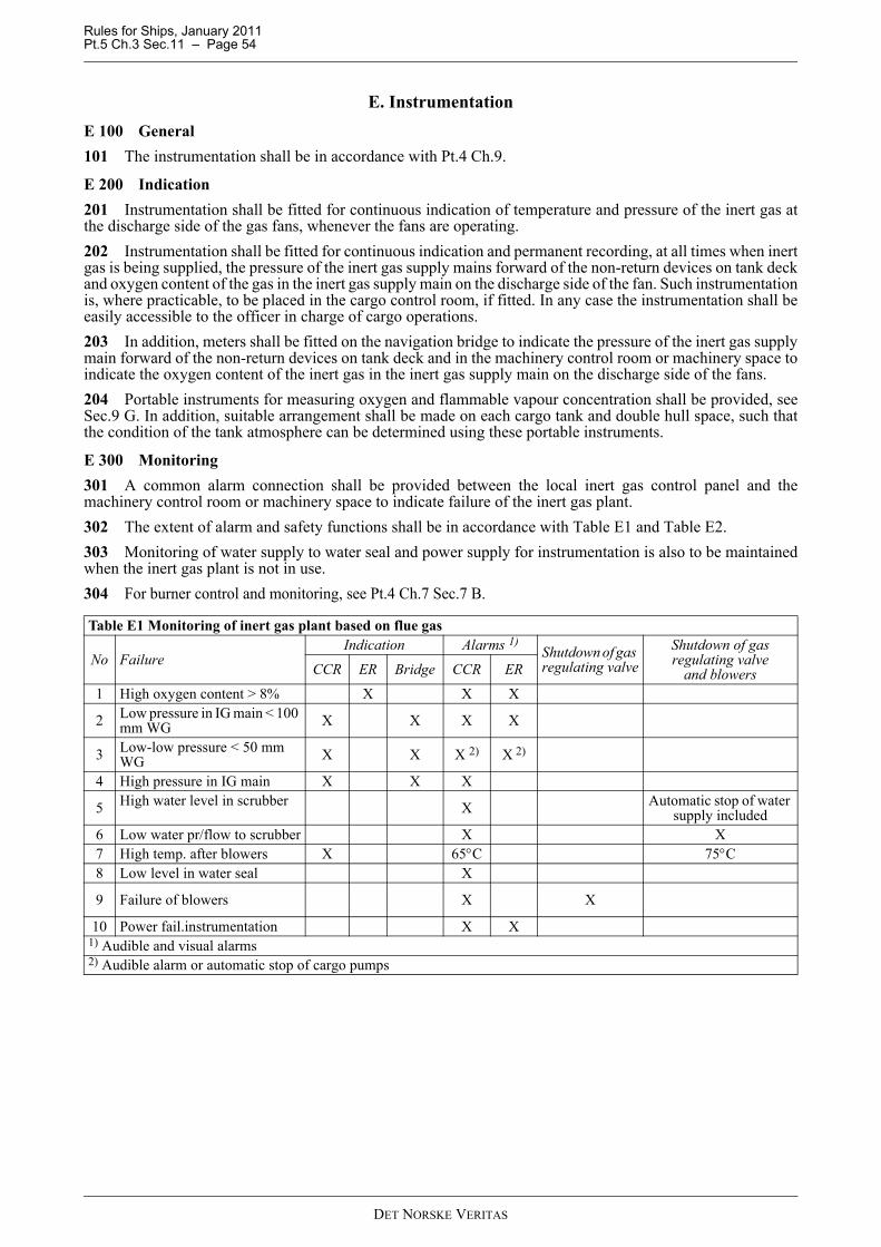
Rules for Ships, January 2011 Pt.5 Ch.3 Sec.11 – Page 54
E. InstrumentationE 100 General101 The instrumentation shall be in accordance with Pt.4 Ch.9.
E 200 Indication201 Instrumentation shall be fitted for continuous indication of temperature and pressure of the inert gas atthe discharge side of the gas fans, whenever the fans are operating.202 Instrumentation shall be fitted for continuous indication and permanent recording, at all times when inertgas is being supplied, the pressure of the inert gas supply mains forward of the non-return devices on tank deckand oxygen content of the gas in the inert gas supply main on the discharge side of the fan. Such instrumentationis, where practicable, to be placed in the cargo control room, if fitted. In any case the instrumentation shall beeasily accessible to the officer in charge of cargo operations.203 In addition, meters shall be fitted on the navigation bridge to indicate the pressure of the inert gas supplymain forward of the non-return devices on tank deck and in the machinery control room or machinery space toindicate the oxygen content of the inert gas in the inert gas supply main on the discharge side of the fans.204 Portable instruments for measuring oxygen and flammable vapour concentration shall be provided, seeSec.9 G. In addition, suitable arrangement shall be made on each cargo tank and double hull space, such thatthe condition of the tank atmosphere can be determined using these portable instruments.
E 300 Monitoring301 A common alarm connection shall be provided between the local inert gas control panel and themachinery control room or machinery space to indicate failure of the inert gas plant.302 The extent of alarm and safety functions shall be in accordance with Table E1 and Table E2.303 Monitoring of water supply to water seal and power supply for instrumentation is also to be maintainedwhen the inert gas plant is not in use.304 For burner control and monitoring, see Pt.4 Ch.7 Sec.7 B.
Table E1 Monitoring of inert gas plant based on flue gas
No FailureIndication Alarms 1)
Shutdown of gas regulating valve
Shutdown of gasregulating valve
and blowersCCR ER Bridge CCR ER
1 High oxygen content > 8% X X X
2 Low pressure in IG main < 100 mm WG X X X X
3 Low-low pressure < 50 mm WG X X X 2) X 2)
4 High pressure in IG main X X X
5 High water level in scrubber X Automatic stop of water supply included
6 Low water pr/flow to scrubber X X7 High temp. after blowers X 65°C 75°C8 Low level in water seal X
9 Failure of blowers X X
10 Power fail.instrumentation X X1) Audible and visual alarms2) Audible alarm or automatic stop of cargo pumps
DET NORSKE VERITAS

Rules for Ships, January 2011 Pt.5 Ch.3 Sec.11 – Page 55
F. Survey and TestingF 100 Survey101 Main components of the inert gas plant shall be surveyed during construction by the surveyor. The gasscrubber and water seal shall be tested for tightness.
102 After completion, the inert gas installation shall be surveyed by the surveyor.
F 200 Testing201 All alarm, shutdown and safety devices shall be function tested.202 A function test of the plant shall be carried out under normal operating conditions, including actualpartial load conditions of boilers.203 The capacity of the plant shall be confirmed by direct measurement of the gas flow or indirectly byrunning against maximum discharge capacity of the cargo oil pumps.
Table E2 Monitoring of inert gas generators
No FailureIndication Alarms 1)
Shutdown of gas regulating valve
Shutdown of gasregulating valve
and blowersCCR ER Bridge CCR ER
1 High oxygen content > 8% X X X
2 Low pressure in IG main < 100 mm WG X X X X
3 Low-low pressure < 50 mm WG X X X 2) X 2)
4 High pressure in IG main X X X
5 High water level in scrubber XAutomatic stop of
water supply included
6 Low water pr/flow to scrubber X X7 High temp. after blowers X 65°C 75°C8 Low level in water seal X9 Failure of blowers/burner X X
10 Power fail.instrumentation X X
11 Insufficient fuel supply X X12 Power failure to generator X X13 Power fail. generator control system X X
1) Audible and visual alarms2) Audible alarm or automatic stop of cargo pumps
Component Certificate CommentInert gas blower/air blower NVInert gas generator NVScrubber NVDeck water seal NVCooling water pump for scrubber NVSea water pump for deck seal NVLiquid p/v breaker WP/V valves T NV or MEDControl & monitoring system NVElectrical motor and motor starter > 100 kW NVNV = DNV product certificateW = Maker's (Works) certificateT = Type approval
DET NORSKE VERITAS

Rules for Ships, January 2011 Pt.5 Ch.3 Sec.12 – Page 56
SECTION 12 PROTECTED SLOP TANK
A. General
A 100 Application
101 The requirements in this section apply to ships with class notation as given in Sec.10 A201.
A 200 Documentation
201 The following plans and specifications shall be submitted for approval:
— arrangement drawings of tanks, cofferdams and venting pipes— schematic drawings of pump and piping systems included blank flanging arrangement and means for gas-
freeing.— schematic drawing of venting system— schematic drawing and specifications of inert gas supply— for fixed gas detection and alarm systems: specification and location of detectors, alarm devices and call
points, and cable routing layout drawing.
202 For requirements related to documentation of instrumentation and automation, including computer basedcontrol and monitoring, see Sec.1.
B. Arrangement and Systems
B 100 Arrangement
101 Where not bounded by weather decks, pump rooms or fuel oil tanks, the slop tank(s) shall be surroundedby cofferdams. These cofferdams shall not be open to a double bottom, pipe tunnel, pump room or otherenclosed space. However, openings provided with gastight bolted covers may be permitted.
102 Cofferdams shall be arranged for water filling and draining.
103 Hatches and other openings to slop tanks shall be arranged for locking in closed position.
B 200 Tank venting
201 Slop tanks shall have a separate, independent venting system with pressure/vacuum relief valves. Gasoutlets shall have a minimum height of 6 m above tank deck and a minimum horizontal distance of 10 m fromopenings to non-hazardous spaces and exhaust outlet from machinery.
B 300 Pumping and piping system
301 Pipe connections to slop tanks shall have means for blank flanging on open deck or at another easilyaccessible location.
302 Pumping system installed for handling of slop while the ship is in service not covered by the classnotation Tanker for Oil or Tanker for Oil Products shall be separated from all other piping systems.Separation from other systems by means of removal of spool pieces may be accepted.
B 400 Gas detection
401 Dry spaces surrounding slop tanks shall be equipped with an approved automatic gas detector systemwith alarm.
B 500 Protection inside slop tanks
501 An arrangement for protecting the tank atmosphere by inert gas or similar effective means, shall beprovided.
502 Meter shall be fitted in the navigation bridge to indicate at all times the pressure in the slop tankswhenever those tanks are isolated from the inert gas supply main.
503 Inerting of slop tank(s) shall be possible irrespective of the blank flanging from the rest of the system.
DET NORSKE VERITAS

Rules for Ships, January 2011 Pt.5 Ch.3 Sec.12 – Page 57
C. Signboards and InstructionsC 100 General101 Signboards with the following text shall be fitted at hatches and other openings to cargo slop tanks: TO BE KEPT CLOSED AND LOCKED DURING HANDLING OF DRY CARGO102 Instructions for handling of slop shall be permanently posted in cargo pump room, cargo control roomand deck office.The following text shall be included in these instructions:«When the ship is on dry cargo service and cargo slop is carried in protected slop tanks, the following itemsshall be complied with:
— All pipe connections to the slop tanks, except vent pipes (and connection to separate slop pumping system)shall be blanked off.
— Inert gas branch connections to the slop tanks shall be kept blanked off, except when filling or re-filling ofinert gas is going on.
— Slop is only to be handled from open deck.— During handling of dry cargo:
— all hatches and openings to the slop tanks shall be kept closed and locked.— the slop tanks shall be kept filled with inert gas, and the O2-content in the tanks shall not exceed 8% by
volume.
— The gas detection system in cofferdams surrounding the slop tanks shall be function tested before loadingof dry cargo commences».
DET NORSKE VERITAS
Rules for Ships, January 2011 Pt.5 Ch.3 Sec.13 – Page 58
SECTION 13 CRUDE OIL WASHING ARRANGEMENTS
A. GeneralA 100 Application101 Crude oil carriers of 20 000 tons deadweight and above shall be fitted with a crude oil washingarrangement complying with MARPOL 73/78 Annex I, Reg. 33 and Reg. 35, which refers to “RevisedSpecifications for the Design, Operation and Control of Crude Oil Washing Systems” adopted by IMO withRes. A.446(XI) as amended by A.497(XII) and A.897(21).102 Crude oil washing installations which are not mandatory according to MARPOL 73/78 Annex I needonly comply with relevant requirements related to safety given in the specifications referred to in 101, such asinstallation of an inert gas system.103 Crude oil carriers (Tanker for Oil) less than 20 000 tons deadweight, fitted with a crude oil washingarrangement complying with design requirements in the specifications referred to in 101, may be assigned thespecial feature notation COW.Documentation requirement A201 8) need not be complied with.
A 200 Documentation201 The following plans and particulars shall be submitted for approval:
1) schematic diagram of the crude oil washing system, including dimensions and materials2) schematic diagram of the stripping and drainage arrangement3) shadow diagrams showing the tank areas covered by direct impingement from the washing machines (not
required for tanks or cargo-holds without internal structure)4) documents showing number, location, make and type of washing machines with nozzle diameters5) drawings showing installation and supporting arrangement for the washing machines6) drawings showing the anchoring of piping for crude oil washing7) drawings showing exact position and arrangement of dipping and gas sampling locations8) operation and equipment manual.
202 For requirements related to documentation of instrumentation and automation, including computer basedcontrol and monitoring, see Sec.1.
DET NORSKE VERITAS

Rules for Ships, January 2011 Pt.5 Ch.3 Sec.14 – Page 59
SECTION 14 OFFSHORE LOADING ARRANGEMENTS
A. GeneralA 100 Application101 The requirements in this section apply to oil carriers having a mooring and loading system for transferof crude oil from offshore loading terminals to the ship.102 The requirements are supplementary to those for the class notation Tanker for Oil.
A 200 Class notation201 Ships having a bow loading arrangement satisfying the requirements of this section, will be assigned theadditional class notation BOW LOADING. 202 Ships having a submerged turret loading arrangement (STL) satisfying the requirements of this section,will be assigned the additional class notation STL.
A 300 Documentation301 In addition to the documentation required for the class notation Tanker for Oil the followingdocumentation shall be submitted for approval:Bow loading
— plans showing the bow loading and mooring arrangement with position of bow loading manifold, fairleadand chain stopper, traction winch, storage reel and bow control station
— plans showing:
— fire protection of the bow area— ventilation of spaces in the bow area.
— operation manual, see G.
Submerged turret loading (STL)
— plans showing the arrangement of the STL room with the mating recess, loading manifold and the hydraulicoperated mating recess hatch
— plans showing:
— fire protection of the STL room— ventilation arrangement— hydraulic system— location of all electrical equipment— position of traction winch and storage reel.
— operation manual, see G.
302 For requirements related to documentation of instrumentation and automation, including computer basedcontrol and monitoring, see Sec.1.
B. MaterialsB 100 General101 Materials used in offshore loading piping systems shall comply with the requirements specified in Sec.4.102 Materials used for the winches and the chain stopper shall comply with the requirements specified in Pt.3Ch.3 Sec.3.
C. Arrangement and General DesignC 100 Positioning of ship101 The ship shall be fitted with controllable pitch propeller and side thrusters of sufficient power for adequatemanoeuvrability and positioning of the ship during offshore loading operations.
DET NORSKE VERITAS
Rules for Ships, January 2011 Pt.5 Ch.3 Sec.14 – Page 60
102 When a dynamic positioning system is installed, this shall include monitoring and self-check facilitiesequivalent to class notation DYNPOS-AUT. Manual override of automatic thruster or propulsion control shallbe arranged.
C 200 Piping system for bow loading201 Cargo pipes and related piping equipment forward of the cargo area shall have only welded connections,except at loading station, and shall be led externally past service and control station and machinery spaces. Suchpipes shall be clearly identified and segregated by at least two valves situated in the cargo area or by one valveand other means together providing an equivalent standard of segregation. The piping shall be self-draining tothe cargo area and into a cargo tank.202 Means shall be provided to allow the bow loading pipe to be purged by inert gas after use and maintainedgas free when not in use.203 The connector shall be fitted with a shut-off valve and a blank flange. The blank flange may be omittedwhen a patent hose coupling is fitted.204 Installation of spray shield at the connector, which will prevent oil leakage from reaching potentialdanger areas, may be required as found necessary. Collecting tray of sufficient capacity, with means fordisposal of drainage, is also to be provided.
C 300 Hazardous areas301 Entrances, air inlets and openings to service and machinery spaces and control stations shall not face thecargo hose connection location, and shall be located at least 10 m from the bow loading hose coupling.302 Spaces housing the loading pipe and loading manifold shall be considered as hazardous area zone 1, withcorresponding requirements to electrical equipment and wiring.303 Spaces considered as non-hazardous shall not have any connections with hazardous spaces or areas, andshall be ventilated in accordance with Sec.6.304 Air vent pipes to the forepeak tank shall be located as far as practicable from hazardous areas.
D. Control and MonitoringD 100 General101 For instrumentation and automation, including computer based control and monitoring, the requirementsin this chapter are additional to those given in Pt.4 Ch.9.
D 200 Control station201 A control station for offshore loading may be arranged within the bow area or on the navigation bridge.From this station all operations concerning positioning of the ship and monitoring of mooring and loadingparameters shall be performed.202 The bridge used in normal sailing mode is the main command location.
D 300 Instrumentation and automation301 Ship manoeuvring instrumentation shall cover:
— variable pitch control— side thruster(s) control— main engine(s) emergency stop, or disengagement of clutch, if fitted— steering gear control— radar— log.
302 Bow mooring instrumentation shall cover:
— mooring line traction control— chain stopper control— data logger system for recording of mooring and load parameters.
The mooring system shall be provided with a tension meter continuously indicating the tension during the bowloading operation. This requirement may be waived if the vessel has in operation an approved dynamicpositioning system.303 STL and bow loading instrumentation shall cover:
DET NORSKE VERITAS

Rules for Ships, January 2011 Pt.5 Ch.3 Sec.14 – Page 61
— indicator for loading connector coupling position— cargo valve position indicators— cargo tank level indicators and high level alarm— a system for automatic transfer of signals from the control and safety system, to enable automatic and
remote control of crude oil transfer pump(s) and closing of valve(s) on offshore terminal.
304 For bow loading arrangement an emergency disconnection system shall be provided. The system shallbe divided into two modes.The first mode shall perform the following functions:
— tripping the main crude oil transfer pumps— closing the connector and loading hose end coupler valves.
Guidance note:Minimum valve closing time should normally not be less than 25 s.
---e-n-d---of---G-u-i-d-a-n-c-e---n-o-t-e---
The second mode shall perform the following functions:
— tripping the main crude oil transfer pumps— closing of the connector and loading hose end coupler valves— opening of the coupler— opening of the chain stopper.
All functions shall be performed in sequence.In addition to the above automatic disconnection systems, a manually-operated backup emergencydisconnection system shall be provided. By this system, individual operation of the chain stopper and couplingbypass locks located in the bow control station, shall be possible.
D 400 Communication401 Means of communication between the control station and the offshore loading terminal shall be providedand certified safe for hazardous areas, if necessary.402 Means of emergency communication between control station and the offshore terminal shall be arranged.403 Both primary and secondary methods shall be provided to ensure that continuous communication can bemaintained between control station and the offshore terminal in the event of any equipment failure or otherproblems arising during the operations.404 A detailed communication sequence shall be established concerning premooring, mooring, preloading,loading and tanker departure phases.
E. Bow Loading Area Safety InstallationsE 100 General101 The entire bow loading area shall be designed with due consideration to means and methods for ensuringa safe and reliable offshore loading operation. The system layout and equipment design shall be optimised withregard to safety aspects.102 Special attention shall be given for minimising the risk for and consequences of fire and explosion causedby system and or equipment failure and/or malfunction.103 The safety installations shall include the following arrangements, equipment and subsystems:
— water jet and foam monitors covering the bow loading and mooring area. Number, location and type ofmonitors shall be optimised with regard to fire-fighting efficiency. The foam system shall be independentfrom the vessel's main foam system
— water-based sprinkler system covering the mooring chain, fairlead and the exterior of the bow controlstation, if fitted
— foam-based sprinkler system for the bow loading connector room— protection for the mooring chain, thimble, shackles, loading hose termination coupling, etc. against contact
with steel structure elements, via use of hardwood or equivalent material— overpressure ventilation for the bow control station, if fitted, as a precaution against ingress of hydrocarbon
gas— natural ventilation of the bow loading connector room— emergency escape route from the bow control station— fire protection standard equal to A-60 class for the floor, door(s), bulkheads and windows of the bow
DET NORSKE VERITAS
Rules for Ships, January 2011 Pt.5 Ch.3 Sec.14 – Page 62
control station— interlock functions to avoid malfunction of the offshore mooring and loading system— emergency disconnection system, to be used if a hazardous situation should arise, see D304.
F. STL Room Safety InstallationsF 100 General101 The safety installations shall include the following arrangements and equipment:
a) A permanent mechanical ventilation system of extraction type shall be installed, capable of circulatingsufficient air to give at least 20 air changes per hour with the following arrangement of exhaust trunking:
— intake just above lower floor plate in the STL room— an intake located 2 m above the lower floor plate and one intake located above deepest water line. These
intakes shall have dampers fitted which can be remotely opened from main deck. The exhaust outletshall be situated at least 3 m above tank deck and 5 m from any opening to non-hazardous spaces.
b) The STL room shall be fitted with interlock between electric lighting and ventilation, so arranged that theventilation must be in operation before the electrical current supply to the room can be connected.
c) Fixed fire-extinguishing system according to SOLAS Ch. II-2/10.9.d) Intrinsically safe electrical circuits.e) Connection for supply of inert gas. If connected permanently to the inert gas system the connection shall
be fitted with a blank flange.f) Certified safe type luminaires of pressurised or flameproof type.g) A fixed gas-detection system. Sampling points or detector heads shall be located at the lower parts of the
room. At least one point shall be located above deepest water line.h) Electrical equipment, instrumentation and automation installed in STL room shall be of certified safe type
and for submerged use (IP 68). Certified safe equipment with degree of protection IP 66 may be acceptedfor installation higher up than 2 m above the deepest water line after consideration in each case.
G. Operation ManualG 100 General101 The ship shall have an approved operation manual on board. The manual shall give informationregarding the safe use of the ship during bow loading or submerged turret loading operations and shall havereferences to enclosed drawings.102 The operation manual is in general to give information regarding the following:
1) Arrangement and equipment
— tank arrangement— cargo transfer system— mooring arrangement— communication system— instrumentation— ventilation equipment.
2) Safety installations
— fire protection and extinction— emergency escape routes— emergency disconnection system— blanking-off of pipes.
3) Operation
— mooring procedure— connection and disconnection of cargo hose coupling— transfer of oil cargo
DET NORSKE VERITAS
Rules for Ships, January 2011 Pt.5 Ch.3 Sec.14 – Page 63
— cargo distribution and loading conditions— precautions against overfilling of tanks.
4) Cleaning and gas-freeing.
H. Tests after InstallationH 100 General101 All arrangement and equipment covered by this section shall be function tested.102 Control of the calibration of the load cell for bow loading shall be carried out by the surveyor.
DET NORSKE VERITAS

Rules for Ships, January 2011 Pt.5 Ch.3 Sec.15 – Page 64
SECTION 15 SINGLE POINT MOORINGS
A. General
A 100 Application101 The requirements in this section apply to ships fitted with equipment enabling them to be moored tosingle point moorings.102 The requirements cover the parts of OCIMF's (Oil Companies' International Marine Forum)“Recommendations for Equipment Employed in the Mooring of Ships at Single Point Moorings” applicablefor the vessel.103 The requirements are supplementary to those for the type notation Tanker for Oil.
A 200 Class notation201 Ships with equipment that satisfies the requirements of this section will be assigned the additionalnotation SPM.
A 300 Documentation301 In addition to the documentation required for the type notation Tanker for Oil, the followingdocumentation shall be submitted for approval:
— plan showing the mooring arrangement with position of bow fairleads, bow chain stoppers, winches andcapstans and possible pedestal rollers and winch storage drum
— details of bow fairleads and their attachment to the bulwark— details of attachment to deck and supporting structure of the bow chain stoppers, winch or capstans as well
as possible pedestal rollers and winch storage drums.
302 A DNV product certificate shall be provided for the following components:
— for bow chain stopper, confirming compliance with C102 and C103 and bow fairlead confirmingcompliance with C103 and C200.
303 The following components shall be provided with documentation of max. SWL from manufacturer(works certificate):
— for winch or capstan, confirming compliance with C401— for pedestal roller, (if fitted) confirming necessary structural strength to withstand the forces to which it
will be exposed when the winch or capstan is lifting with its maximum capacity.
B. Materials
B 100 General101 The materials used in bow fairleads shall comply with the requirements specified in Pt.2 Ch.2.102 The materials used for bow chain stopper shall comply with the requirements specified in Pt.3 Ch.3Sec.3.
C. Arrangement and General Design
C 100 Bow chain stoppers101 The arrangement and capacity shall be in accordance with Table C1.102 A standard 76 mm stud-link chain shall be secured when the chain engaging pawl or bar is in closedposition. When in open position, the chain and associated fittings shall be allowed to pass freely.103 The structural strength of the stopper, bow fairlead and supporting structure shall be based on a safetyfactor of 2.0 against the yield criterion when applying a load equal to SWL.104 Stoppers shall be located between 2.7 and 3.7 m inboard from the bow fairlead.105 When positioning, due consideration shall be given to the correct alignment of stoppers relative to the
DET NORSKE VERITAS
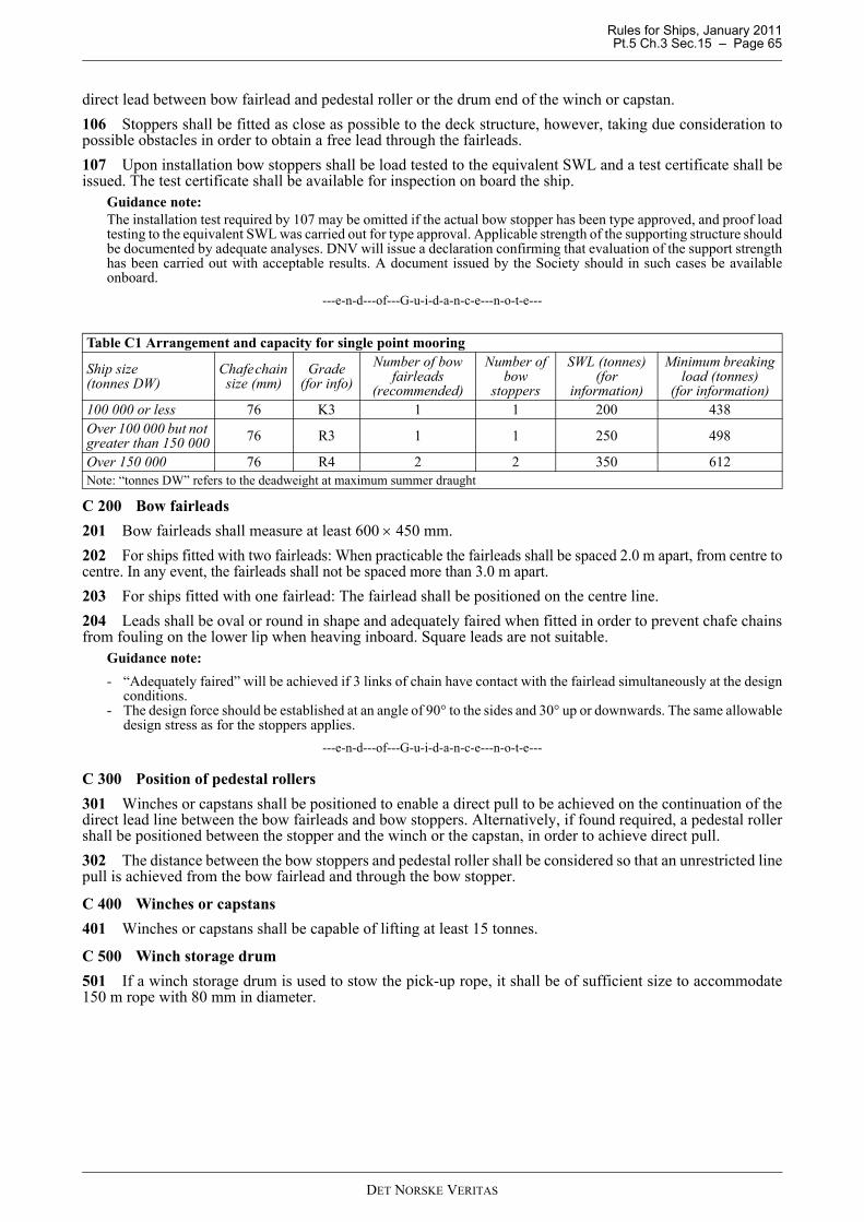
Rules for Ships, January 2011 Pt.5 Ch.3 Sec.15 – Page 65
direct lead between bow fairlead and pedestal roller or the drum end of the winch or capstan.106 Stoppers shall be fitted as close as possible to the deck structure, however, taking due consideration topossible obstacles in order to obtain a free lead through the fairleads.107 Upon installation bow stoppers shall be load tested to the equivalent SWL and a test certificate shall beissued. The test certificate shall be available for inspection on board the ship.
Guidance note:The installation test required by 107 may be omitted if the actual bow stopper has been type approved, and proof loadtesting to the equivalent SWL was carried out for type approval. Applicable strength of the supporting structure shouldbe documented by adequate analyses. DNV will issue a declaration confirming that evaluation of the support strengthhas been carried out with acceptable results. A document issued by the Society should in such cases be availableonboard.
---e-n-d---of---G-u-i-d-a-n-c-e---n-o-t-e---
C 200 Bow fairleads201 Bow fairleads shall measure at least 600 × 450 mm.202 For ships fitted with two fairleads: When practicable the fairleads shall be spaced 2.0 m apart, from centre tocentre. In any event, the fairleads shall not be spaced more than 3.0 m apart.203 For ships fitted with one fairlead: The fairlead shall be positioned on the centre line.204 Leads shall be oval or round in shape and adequately faired when fitted in order to prevent chafe chainsfrom fouling on the lower lip when heaving inboard. Square leads are not suitable.
Guidance note:- “Adequately faired” will be achieved if 3 links of chain have contact with the fairlead simultaneously at the design
conditions.- The design force should be established at an angle of 90° to the sides and 30° up or downwards. The same allowable
design stress as for the stoppers applies.---e-n-d---of---G-u-i-d-a-n-c-e---n-o-t-e---
C 300 Position of pedestal rollers301 Winches or capstans shall be positioned to enable a direct pull to be achieved on the continuation of thedirect lead line between the bow fairleads and bow stoppers. Alternatively, if found required, a pedestal rollershall be positioned between the stopper and the winch or the capstan, in order to achieve direct pull.302 The distance between the bow stoppers and pedestal roller shall be considered so that an unrestricted linepull is achieved from the bow fairlead and through the bow stopper.
C 400 Winches or capstans401 Winches or capstans shall be capable of lifting at least 15 tonnes.
C 500 Winch storage drum501 If a winch storage drum is used to stow the pick-up rope, it shall be of sufficient size to accommodate150 m rope with 80 mm in diameter.
Table C1 Arrangement and capacity for single point mooring
Ship size (tonnes DW)
Chafe chain size (mm)
Grade (for info)
Number of bow fairleads
(recommended)
Number of bow
stoppers
SWL (tonnes) (for
information)
Minimum breaking load (tonnes)
(for information)100 000 or less 76 K3 1 1 200 438Over 100 000 but not greater than 150 000 76 R3 1 1 250 498
Over 150 000 76 R4 2 2 350 612Note: “tonnes DW” refers to the deadweight at maximum summer draught
DET NORSKE VERITAS

Rules for Ships, January 2011 Pt.5 Ch.3 App.A – Page 66
APPENDIX A LIST OF CARGOES
A. List of Oil CargoesA 100 General101 This list specifies oil cargoes 1) which may be carried on ships with class notation Tanker for Oil andTanker for Oil Products 2)
Asphalt solutions
— Blending Stocks— Roofers Flux— Straight Run Residue.
Oils
— Clarified— Crude Oil— Mixtures containing crude oil— Diesel Oil— Fuel Oil No. 4— Fuel Oil No. 5— Fuel Oil No. 6— Residual Fuel Oil— Road Oil— Transformer Oil— Aromatic Oil— Lubricating Oils and Blending Stocks— Mineral Oil— Motor Oil— Penetrating Oil— Spindle Oil— Turbine Oil.
Distillates
— Straight Run— Flashed Feed Stocks.
Gas Oil
— Cracked.
Gasoline Blending Stocks
— Alkylates — fuel— Reformates— Polymer — fuel.
Gasolines
— Casing head (natural)— Automotive— Aviation— Straight Run— Fuel Oil No. 1 (Kerosene)— Fuel Oil No. 1-D— Fuel Oil No. 2— Fuel Oil No. 2-D.
Jet Fuels
— JP-1 (Kerosene)— JP-3— JP-4— JP-5 (Kerosene, Heavy)
DET NORSKE VERITAS
Rules for Ships, January 2011 Pt.5 Ch.3 App.A – Page 67
— Turbo Fuel— Kerosene— Mineral Spirit.
Naphtha
— Solvent— Petroleum— Heartcut Distillate Oil.
1) The list of oils shall not necessarily be considered as comprehensive.2) May carry all the listed oil cargoes except crude oil.
B. Cargoes other than OilsB 100 Cargoes and conditions for carriage101 Cargoes other than oils may be carried by ships with class notation Tanker for Oil Products asfollows:
a) OS (Other substances), as per IBC Code Chapter 18 may be carried. No MARPOL requirements apply.b) Pollution category Z, as per IBC code Chapter 18 may be carried by ships which comply with relevant
requirements for the NLS class notation (Sec.1 A402). In addition, relevant safety criteria such as possibleincreased foam fire extinguishing requirement must be complied with. Density of the product will need tobe considered additionally.
DET NORSKE VERITAS