DNV Ship rules Pt.3 Ch.3 Hull equipment and...
138
RULES FOR CLASSIFICATION OF DET NORSKE VERITAS AS The content of this service document is the subject of intellectual property rights reserved by Det Norske Veritas AS (DNV). The user accepts that it is prohibited by anyone else but DNV and/or its licensees to offer and/or perform classification, certification and/or verification services, including the issuance of certificates and/or declarations of conformity, wholly or partly, on the basis of and/or pursuant to this document whether free of charge or chargeable, without DNV's prior written consent. DNV is not responsible for the consequences arising from any use of this document by others. The electronic pdf version of this document found through http://www.dnvgl.com is the officially binding version Ships PART 3 CHAPTER 3 NEWBUILDINGS HULL AND EQUIPMENT – MAIN CLASS Hull equipment and safety JANUARY 2016
Transcript of DNV Ship rules Pt.3 Ch.3 Hull equipment and...

RULES FOR CLASSIFICATION OF
The content of thisaccepts that it is pverification servicepursuant to this docconsequences arisin
The electronic p
Ships
PART 3 CHAPTER 3
NEWBUILDINGSHULL AND EQUIPMENT – MAIN CLASS
Hull equipment and safetyJANUARY 2016
DET NORSKE VERITAS AS
service document is the subject of intellectual property rights reserved by Det Norske Veritas AS (DNV). The userrohibited by anyone else but DNV and/or its licensees to offer and/or perform classification, certification and/ors, including the issuance of certificates and/or declarations of conformity, wholly or partly, on the basis of and/orument whether free of charge or chargeable, without DNV's prior written consent. DNV is not responsible for theg from any use of this document by others.
df version of this document found through http://www.dnvgl.com is the officially binding version
FOREWORD
DNV is a global provider of knowledge for managing risk. Today, safe and responsible business conduct is both a licenseto operate and a competitive advantage. Our core competence is to identify, assess, and advise on risk management. Fromour leading position in certification, classification, verification, and training, we develop and apply standards and bestpractices. This helps our customers safely and responsibly improve their business performance. DNV is an independentorganisation with dedicated risk professionals in more than 100 countries, with the purpose of safeguarding life, propertyand the environment.
The Rules lay down technical and procedural requirements related to obtaining and retaining a Class Certificate. It is usedas a contractual document and includes both requirements and acceptance criteria.
© Det Norske Veritas AS January 2016
Any comments may be sent by e-mail to [email protected]
If any person suffers loss or damage which is proved to have been caused by any negligent act or omission of Det Norske Veritas, then Det Norske Veritas shall pay compensation tosuch person for his proved direct loss or damage. However, the compensation shall not exceed an amount equal to ten times the fee charged for the service in question, provided thatthe maximum compensation shall never exceed USD 2 million.In this provision “Det Norske Veritas” shall mean the Foundation Det Norske Veritas as well as all its subsidiaries, directors, officers, employees, agents and any other acting on behalfof Det Norske Veritas.

Rules for Ships, January 2016Pt.3 Ch.3 CHANGES – CURRENT – Page 3
CHANGES – CURRENT
General
This document supersedes the January 2015 edition.
Text affected by the main changes in this edition is highlighted in red colour. However, if the changes involve
Det Norske Veritas AS, company registration number 945 748 931, has on 27th November 2013 changed itsname to DNV GL AS. For further information, see www.dnvgl.com. Any reference in this document to“Det Norske Veritas AS” or “DNV” shall therefore also be a reference to “DNV GL AS”.
a whole chapter, section or sub-section, normally only the title will be in red colour.
Main changes January 2016, entering into force July 2016
• Sec.2 Sternframes, rudders and steering— A201: Reference to S10 has been deleted.— B101: Reference to S6 has been deleted.— B303: Reference to S10 has been deleted.— B303: Table B2 has been updated.— D101: Reference to S10 has been deleted.— D101: Table D1 has been updated. — E: Heading has been modified.— E303: Allowable bending stress has been decreased.— E304: Section modulus requirement have been increased.— E402: Additional requirement for rudder horn thickness.— E405: Additional requirements for rudder horn arrangement.— E405: Description of alternative rudder horn design (non-continuous rudder horn plating) has been
removed.— E500: New requirements for rudder trunk.— F101: Text related to single plate rudders has been added.— F103: Additional requirement to semi-spade rudders.— F302: Figure 10 has been updated.— F500: New requirements to connections of rudder blade structure with solid parts.— F601: Rudder force has been clarified.— F602: Blade thickness requirement has been clarified.— F603: Section modulus requirement has been clarified— G204: Push-up pressure calculation has been modified.— G205. Key requirement has been modified.— G403: Pintle diameter requirement has been modified.— G404: New guidance note regarding securing of bushings.— G405: Reference to S10 has been deleted.— G406: Push-up pressure calculation has been modified.— J102: Steel backing bar allowed.— J104: Slot welding application area has been clarified.— J202: The term “pull-up” has been changed to “push-up”.
• Sec.5 Lifting appliances and foundations for heavy equipment, deck machinery and towing equipment
— C303: The rule name has been updated.
In addition to the above stated main changes, editorial corrections may have been made.
Editorial corrections
DET NORSKE VERITAS AS

Rules for Ships, January 2016 Pt.3 Ch.3 Contents – Page 4
CONTENTS
CHANGES – CURRENT ................................................................................................................................................... 3
Sec. 1 General requirements ........................................................................................................................ 9
A. Classification.................................................................................................................................................................. 9A 100 Application............................................................................................................................................................ 9
B. Definitions ...................................................................................................................................................................... 9B 100 Symbols ................................................................................................................................................................ 9
C. Documentation .............................................................................................................................................................. 9C 100 General.................................................................................................................................................................. 9
D. Materials ........................................................................................................................................................................ 9D 100 Use of asbestos ..................................................................................................................................................... 9
Sec. 2 Sternframes, rudders and steering ................................................................................................ 10
A. General ......................................................................................................................................................................... 10A 100 Introduction......................................................................................................................................................... 10A 200 Definitions .......................................................................................................................................................... 10A 300 Documentation requirements .............................................................................................................................. 12
B. Materials ...................................................................................................................................................................... 12B 100 Plates and sections .............................................................................................................................................. 12B 200 Forgings and castings.......................................................................................................................................... 13B 300 Bearing materials ................................................................................................................................................ 13B 400 Certification ........................................................................................................................................................ 14B 500 Heat treatment..................................................................................................................................................... 14
C. Arrangement and details ............................................................................................................................................ 14C 100 Sternframes and rudders ..................................................................................................................................... 14
D. Design loads and stress analysis................................................................................................................................. 15D 100 Rudder force and rudder torque, general ........................................................................................................... 15D 200 Rudders with stepped contours ........................................................................................................................... 16D 300 Stress analysis ..................................................................................................................................................... 17
E. Sternframes, sole pieces, rudder horns, and rudder trunks ................................................................................... 18E 100 General................................................................................................................................................................ 18E 200 Propeller posts..................................................................................................................................................... 18E 300 Sole pieces .......................................................................................................................................................... 19E 400 Rudder horns....................................................................................................................................................... 20E 500 Rudder trunk ....................................................................................................................................................... 23
F. Rudders ........................................................................................................................................................................ 24F 100 General arrangement and details......................................................................................................................... 24F 200 Rudder plating..................................................................................................................................................... 25F 300 Rudder bending................................................................................................................................................... 25F 400 Web plates........................................................................................................................................................... 26F 500 Connections of rudder blade structure with solid parts ...................................................................................... 27F 600 Single plate rudders ............................................................................................................................................ 28
G. Rudder stocks and shafts............................................................................................................................................ 28G 100 General................................................................................................................................................................ 28G 200 Rudder stock with couplings............................................................................................................................... 29G 300 Rudder shaft ........................................................................................................................................................ 35G 400 Bearings and pintles ........................................................................................................................................... 36
H. Propeller nozzles ......................................................................................................................................................... 38H 100 General................................................................................................................................................................ 38H 200 Plating ................................................................................................................................................................. 38H 300 Nozzle ring stiffness ........................................................................................................................................... 38H 400 Welding............................................................................................................................................................... 39H 500 Supports .............................................................................................................................................................. 39
I. Propeller shaft brackets.............................................................................................................................................. 39I 100 General................................................................................................................................................................ 39I 200 Arrangement ....................................................................................................................................................... 39I 300 Struts ................................................................................................................................................................... 39
DET NORSKE VERITAS AS

Rules for Ships, January 2016 Pt.3 Ch.3 Contents – Page 5
J. Welding, mounting and testing .................................................................................................................................. 40J 100 Welding............................................................................................................................................................... 40J 200 Rudders and rudder stock connections ............................................................................................................... 40J 300 Testing of stern frames and rudders.................................................................................................................... 40J 400 Mounting of rudder ............................................................................................................................................. 40
Sec. 3 Anchoring and mooring equipment ............................................................................................... 42
A. General ......................................................................................................................................................................... 42A 100 Introduction......................................................................................................................................................... 42A 200 Documentation requirement................................................................................................................................ 42A 300 Certification ........................................................................................................................................................ 42A 400 Assumptions........................................................................................................................................................ 43
B. Structural arrangement for anchoring equipment .................................................................................................. 43B 100 General ............................................................................................................................................................... 43
C. Equipment specification ............................................................................................................................................. 44C 100 Equipment number.............................................................................................................................................. 44C 200 Equipment tables................................................................................................................................................. 47
D. Anchors ........................................................................................................................................................................ 48D 100 General................................................................................................................................................................ 48D 200 Materials ............................................................................................................................................................. 49D 300 Anchor shackle.................................................................................................................................................... 49D 400 Manufacturing..................................................................................................................................................... 49D 500 Testing ................................................................................................................................................................ 49D 600 Additional requirements for H.H.P. and S.H.H.P. anchors ................................................................................ 51D 700 Identification ....................................................................................................................................................... 51
E. Anchor chain cables .................................................................................................................................................... 52E 100 General requirements .......................................................................................................................................... 52E 200 Materials and manufacture.................................................................................................................................. 54E 300 Heat treatment..................................................................................................................................................... 54E 400 Proof load testing ................................................................................................................................................ 54E 500 Breaking load testing .......................................................................................................................................... 54E 600 Mechanical testing .............................................................................................................................................. 57E 700 Inspection and dimensional tolerances ............................................................................................................... 59E 800 Identification ....................................................................................................................................................... 59E 900 Certification ........................................................................................................................................................ 60
F. Windlass and chain stoppers ..................................................................................................................................... 60F 100 General design .................................................................................................................................................... 60F 200 Materials ............................................................................................................................................................. 61F 300 Testing ................................................................................................................................................................ 61
G. Towlines and mooring lines ....................................................................................................................................... 62G 100 General................................................................................................................................................................ 62G 200 Materials ............................................................................................................................................................. 62G 300 Testing of steel wire ropes .................................................................................................................................. 63G 400 Testing of natural fibre ropes.............................................................................................................................. 64G 500 Mooring Winches ............................................................................................................................................... 64
Sec. 4 Masts and rigging ............................................................................................................................. 65
A. General ......................................................................................................................................................................... 65A 100 Introduction......................................................................................................................................................... 65A 200 Assumptions........................................................................................................................................................ 65A 300 Definitions .......................................................................................................................................................... 65A 400 Documentation requirements .............................................................................................................................. 66
B. Materials and welding ................................................................................................................................................ 66B 100 Materials ............................................................................................................................................................. 66
C. Arrangement and support.......................................................................................................................................... 66C 100 Masts and posts ................................................................................................................................................... 66C 200 Standing rigging.................................................................................................................................................. 66
D. Design and scantlings.................................................................................................................................................. 66D 100 General................................................................................................................................................................ 66D 200 Unstayed masts and posts with derricks ............................................................................................................. 67D 300 Stayed masts or posts with derricks with a lifting capacity not exceeding 10 t.................................................. 67D 400 Stayed masts of posts with derricks with a lifting capacity of 10 t or more, but not exceeding 40 t ................. 67D 500 Stayed masts without derricks ............................................................................................................................ 68D 600 Shrouds ............................................................................................................................................................... 68
DET NORSKE VERITAS AS

Rules for Ships, January 2016 Pt.3 Ch.3 Contents – Page 6
Sec. 5 Lifting appliances and foundations for heavy equipment, deck machinery and towing equipment ............................................................................................................................. 70
A. Crane and lifting appliances ...................................................................................................................................... 70A 100 Introduction ........................................................................................................................................................ 70A 200 Documentation requirements .............................................................................................................................. 70A 300 Materials ............................................................................................................................................................. 71A 400 Arrangement ....................................................................................................................................................... 71A 500 Design loads........................................................................................................................................................ 72A 600 Allowable stresses............................................................................................................................................... 73A 700 Testing ................................................................................................................................................................ 73
B. Foundations for heavy equipment, winches, windlasses and other pulling accessories ....................................... 73B 100 Introduction......................................................................................................................................................... 73B 200 Documentation requirements .............................................................................................................................. 73B 300 Design loads and allowable stresses ................................................................................................................... 73B 400 Securing requirements for fore deck windlasses ................................................................................................ 74B 500 Materials ............................................................................................................................................................. 76
C. Shipboard fittings and supporting hull structures associated with towing and mooring on conventional vessels ........................................................................................................................ 77
C 100 Introduction......................................................................................................................................................... 77C 200 Documentation requirements .............................................................................................................................. 78C 300 General................................................................................................................................................................ 78C 400 Towing ................................................................................................................................................................ 79C 500 Mooring .............................................................................................................................................................. 79C 600 Materials ............................................................................................................................................................. 80
Sec. 6 Openings and closing appliances .................................................................................................... 81
A. General ......................................................................................................................................................................... 81A 100 Application.......................................................................................................................................................... 81A 200 Definitions .......................................................................................................................................................... 81A 300 Documentation requirements .............................................................................................................................. 82A 400 On board documentation..................................................................................................................................... 83A 500 Testing ................................................................................................................................................................ 83A 600 Certificate requirements...................................................................................................................................... 83
B. Access openings in superstructures and freeboard deck ..................................................................................................................................................... 84
B 100 Doors................................................................................................................................................................... 84B 200 Sill heights .......................................................................................................................................................... 84B 300 Access openings in freeboard and superstructure decks..................................................................................... 85B 400 Strength and securing of small hatches on the exposed fore deck...................................................................... 85
C. Side and stern doors.................................................................................................................................................... 88C 100 General................................................................................................................................................................ 88C 200 Structural arrangement........................................................................................................................................ 88C 300 Design loads........................................................................................................................................................ 88C 400 Plating ................................................................................................................................................................. 89C 500 Stiffeners ............................................................................................................................................................. 89C 600 Girders ................................................................................................................................................................ 90C 700 Allowable stress .................................................................................................................................................. 90C 800 Closing arrangement, general ............................................................................................................................. 90C 900 Closing arrangement, strength ............................................................................................................................ 91C 1000 Closing arrangement, system for operation and indication/monitoring.............................................................. 91
D. Hatchway coamings .................................................................................................................................................... 93D 100 General................................................................................................................................................................ 93D 200 Coaming heights ................................................................................................................................................. 93D 300 Scantlings............................................................................................................................................................ 93
E. Hatch covers ................................................................................................................................................................ 94E 100 General................................................................................................................................................................ 94E 200 Design loads........................................................................................................................................................ 94E 300 Plating ................................................................................................................................................................. 97E 400 Stiffeners ............................................................................................................................................................. 97E 500 Girders ................................................................................................................................................................ 98E 600 Stiffness of cover edges ...................................................................................................................................... 99E 700 Structural analysis............................................................................................................................................... 99E 800 Buckling control ............................................................................................................................................... 100E 900 Deflection limit and connections between hatch cover panels ......................................................................... 100E 1000 Corrosion addition and steel renewal................................................................................................................ 100
DET NORSKE VERITAS AS

Rules for Ships, January 2016 Pt.3 Ch.3 Contents – Page 7
F. Hatchway tightness arrangement and closing devices........................................................................................... 101F 100 General.............................................................................................................................................................. 101F 200 Design and tightness requirements ................................................................................................................... 101F 300 Securing devices in general .............................................................................................................................. 102F 400 Securing arrangement for weathertight hatch covers........................................................................................ 102F 500 Securing arrangement for deep tank or cargo oil tank hatch covers................................................................. 103F 600 Securing arrangement for hatch covers carrying deck cargo............................................................................ 104F 700 Securing arrangement for hatch covers in watertight decks ............................................................................. 104F 800 Drainage arrangement....................................................................................................................................... 104
G. Internal doors and hatches for watertight integrity ............................................................................................................................................. 104
G 100 General.............................................................................................................................................................. 104G 200 Operation .......................................................................................................................................................... 105G 300 Strength ............................................................................................................................................................. 105
H. Ventilators.................................................................................................................................................................. 106H 100 Coamings and closing arrangements ................................................................................................................ 106H 200 Thickness of coamings...................................................................................................................................... 106H 300 Arrangement and support.................................................................................................................................. 106H 400 Strength requirements for fore deck ventilators................................................................................................ 107
I. Tank access, ullage and ventilation openings ......................................................................................................... 108I 100 General.............................................................................................................................................................. 108I 200 Hatchways......................................................................................................................................................... 108I 300 Air Pipes ........................................................................................................................................................... 108I 400 Strength requirements for fore deck air pipes................................................................................................... 109
J. Machinery space openings........................................................................................................................................ 111J 100 Openings ........................................................................................................................................................... 111
K. Scuppers, inlets and discharges ............................................................................................................................... 111K 100 Inlets and discharges ......................................................................................................................................... 111K 200 Pipe thickness ................................................................................................................................................... 113K 300 Scuppers............................................................................................................................................................ 113K 400 Periodically unmanned machinery space.......................................................................................................... 114K 500 Garbage chutes.................................................................................................................................................. 114K 600 Spurling pipes and cable lockers....................................................................................................................... 115
L. Side scuttles, windows and skylights ....................................................................................................................... 115L 100 Application and General Requirements ............................................................................................................ 115L 200 Definitions ........................................................................................................................................................ 115L 300 Document requirements .................................................................................................................................... 115L 400 Arrangement and positioning............................................................................................................................ 115L 500 Design loads ..................................................................................................................................................... 116L 600 Glass thickness.................................................................................................................................................. 116L 700 Mounting frame design ..................................................................................................................................... 117L 800 Testing requirements......................................................................................................................................... 118
M.Freeing ports.............................................................................................................................................................. 119M 100 Definitions ........................................................................................................................................................ 119M 200 Freeing port area ............................................................................................................................................... 119M 300 Location and protection of openings................................................................................................................. 120M 400 Multiple wells ................................................................................................................................................... 120M 500 Free flow area ................................................................................................................................................... 120M 600 Type «A», «B-100» and «B-60» ships ............................................................................................................. 120
N. Special requirements for Type A Ships................................................................................................................... 121N 100 Machinery casings ............................................................................................................................................ 121N 200 Gangway and access ......................................................................................................................................... 121N 300 Hatchways......................................................................................................................................................... 121N 400 Freeing arrangements........................................................................................................................................ 121
O. Retractable bottom equipment ................................................................................................................................ 121O 100 Introduction....................................................................................................................................................... 121O 200 Arrangement ..................................................................................................................................................... 121O 300 Design loads and allowable stresses ................................................................................................................. 121
P. Box coolers ................................................................................................................................................................. 122P 100 Introduction....................................................................................................................................................... 122P 200 Arrangement ..................................................................................................................................................... 122
DET NORSKE VERITAS AS

Rules for Ships, January 2016 Pt.3 Ch.3 Contents – Page 8
Sec. 7 Corrosion prevention ..................................................................................................................... 123
A. Corrosion prevention systems.................................................................................................................................. 123A 100 General.............................................................................................................................................................. 123A 200 Documentation requirements ............................................................................................................................ 123A 300 Corrosion prevention of dedicated seawater ballast tanks................................................................................ 123A 400 Coatings ............................................................................................................................................................ 123A 500 Cathodic protection........................................................................................................................................... 123
Sec. 8 Protection of the crew .................................................................................................................... 125
A. Protection of the crew ............................................................................................................................................... 125A 100 Guard rails......................................................................................................................................................... 125A 200 Gangways, walkways and passageways ........................................................................................................... 126
Sec. 9 Stability ........................................................................................................................................... 129
A. Application, definitions and document requirements ........................................................................................... 129A 100 Application........................................................................................................................................................ 129A 200 Terms ................................................................................................................................................................ 129A 300 Documentation requirements ............................................................................................................................ 130
B. Surveys and tests ...................................................................................................................................................... 130B 100 General.............................................................................................................................................................. 130
C. General requirements ............................................................................................................................................... 130C 100 Stability book.................................................................................................................................................... 130C 200 Fixed ballast ...................................................................................................................................................... 130C 300 Draught marks................................................................................................................................................... 130C 400 Loading computer system................................................................................................................................. 131
D. Intact stability criteria ............................................................................................................................................. 131D 100 General stability criteria.................................................................................................................................... 131D 200 Weather criterion .............................................................................................................................................. 132D 300 Assumptions concerning intact stability criteria and calculations.................................................................... 135
E. Damage stability ........................................................................................................................................................ 136E 100 Damage stability ............................................................................................................................................... 136
F. Determination of lightweight data........................................................................................................................... 136F 100 Application........................................................................................................................................................ 136F 200 Procedure .......................................................................................................................................................... 136F 300 Lightweight survey ........................................................................................................................................... 136
CHANGES – HISTORIC ............................................................................................................................................... 137
DET NORSKE VERITAS AS
Rules for Ships, January 2016 Pt.3 Ch.3 Sec.1 General requirements – Page 9
SECTION 1 GENERAL REQUIREMENTS
A. Classification
A 100 Application
101 The Rules in this chapter apply to steering arrangement and anchoring, mooring and load handlingequipment.
102 Necessary strengthening of the hull structure due to loads imposed by the equipment and installations aregiven where appropriate.
B. Definitions
B 100 Symbols
101
L = Rule length in m 1)
B = Rule breadth in m 1)
D = Rule depth in m 1)
T = Rule draught in m 1)
Δ = Rule displacement in t 1)
CB = Rule block coefficient 1)
V = maximum service speed in knots on draught T.
1) For details see Ch.1 Sec.1 B
C. Documentation
C 100 General
101 Plans and particulars to be submitted for approval or information are specified in the respective sectionsof this chapter.
D. Materials
D 100 Use of asbestos
101 The use of asbestos is prohibited. (Ref. Pt.1. Ch.1 Sec.2 A204 and Sec.4 A203).
DET NORSKE VERITAS AS

Rules for Ships, January 2016 Pt.3 Ch.3 Sec.2 Sternframes, rudders and steering – Page 10
SECTION 2 STERNFRAMES, RUDDERS AND STEERING
A. General
A 100 Introduction
101 Vessels shall be provided with means for steering (directional control) of adequate strength and suitabledesign. The means for steering shall be capable of steering the ship at maximum ahead service speed, whichshall be demonstrated.
102 Steering may be achieved by means of rudders, foils, flaps, steerable propellers or jets, yaw control portsor side thrusters, differential propulsive thrust, variable geometry of the vessel or its lift system components,or by any combination of these devices.
103 Requirements in this section are related to rudder and rudder design. For requirement to steering gearoperating the rudder, reference is made to Pt.4 Ch.14 Sec.1.If steering is achieved by means of waterjet or thrusters reference is made to Pt.4 Ch.5 Sec.2 and Sec.3respectively. Other means of steering is subject to special consideration.
A 200 Definitions
201 Maximum ahead service speed is the maximum service speed Vstr.The speed shall be specified by designer and with consideration to necessary steering gear capacity.Vstr may be equal to or higher than maximum service speed with the ship at summer load waterline, V.
202 Maximum astern speed is the speed which it is estimated the ship can attain at the designed maximumastern power at the deepest seagoing draught.
203 Some terms used for rudder, rudder stock and supporting structure are shown in Fig.1.
DET NORSKE VERITAS AS

Rules for Ships, January 2016 Pt.3 Ch.3 Sec.2 Sternframes, rudders and steering – Page 11
Fig. 1Rudders
204 Symbols:
f1 = material factor, see Bpm = maximum bearing surface pressure, see BFR = design rudder force, see DMTR= design rudder torque, see DA = total area in m2 of rudder bladeH = mean rudder height in m.
DET NORSKE VERITAS AS

Rules for Ships, January 2016 Pt.3 Ch.3 Sec.2 Sternframes, rudders and steering – Page 12
A 300 Documentation requirements
301 Documentation shall be submitted as required by Table A1.
302 For general requirements to documentation, see Pt.0 Ch.3 Sec.1.
303 For a full definition of the documentation types, see Pt.0 Ch.3 Sec.2.
B. Materials
B 100 Plates and sections
101 Selection of material grades for plates and sections for sternframes, rudders, rudder horns and shaftbrackets are in general not to be of lower grades as given in Table B1.
For rudder and rudder body plates subjected to stress concentrations (e.g. in way of lower support of semi-spaderudders or at upper part of spade rudders) Class IV as given in Pt.3 Ch.1 Sec.2 Table B1 shall be applied.
Table A1 Documentation requirementsObject Documentation type Additional description For approval (AP) or
For information (FI)
Rudder arrangement Z030 – Arrangement plan
Covering rudders, propeller outlines, actuators, stocks, horns, stoppers and bearing lubrication system.Specify maximum speed ahead and aft, and Ice Class when applicable.
FI
Z250 – Procedure Mounting and dismounting or rudder (including flaps as a detached component), rudder stock and pintles.
FI
Z250 – Procedure Measurement of bearing clearances. FI
Z180 – Maintenance manual
Flap rudders: Hinges, link systems and criteria for allowable bearing clearances.
FI
Z110 – Data sheet Non-conventional rudder designs: Torque characteristics (torque versus rudder angle in homogeneous water stream).
FI
Z240 – Calculation report*
Expected life time of bearings subjected to extraordinary wear rate due to dynamic positioning.
AP
Stern frame, sole pieces and rudder horns
H050 – Structural drawing
AP
Rudder blades H050 – Structural drawing
Including details of bearings, shafts and pintles. AP
Rudder stocks H050 – Structural drawing
Including details of connections, bolts and keys. AP
Propeller nozzles H050 – Structural drawing
AP
Propeller shaft brackets H050 – Structural drawing
AP
Rudder and steering gear supporting structures
H050 – Structural drawing
Including fastening arrangements (bolts, cocking and side stoppers).
AP
* Only for rudders included under DP-Control documentation, see Pt.6 Ch.7.
Table B1 Plate material gradesThickness in mm Normal strength structural steel High strength structural steel
t ≤ 20 A A20 < t ≤ 25 B A25 < t ≤ 40 D D40 < t ≤ 150 E E
DET NORSKE VERITAS AS
Rules for Ships, January 2016 Pt.3 Ch.3 Sec.2 Sternframes, rudders and steering – Page 13
102 The material factor f1 included in the various formulae for structures may be taken as:f1 = 1.0 for NV-NS steelf1 = 1.08 for NV-27 steelf1 = 1.28 for NV-32 steelf1 = 1.39 for NV-36 steelf1 = 1.47 for NV-40 steel
B 200 Forgings and castings
201 Rudder stocks, pintles, coupling bolts, keys, stern frames, rudder horns and rudder members shall bemade of rolled, forged or cast carbon manganese or alloy steel in accordance with Pt.2 Ch.2.
Guidance note:Rudder stocks and pintles should be of weldable quality in order to obtain satisfactory weldability for any futurerepairs by welding in service. Note that forgings and castings shall be Charpy tested.
---e-n-d---of---g-u-i-d-a-n-c-e---n-o-t-e---
For rudder stocks, pintles, keys and bolts the minimum yield stress shall not be less than 200 N/mm2.
202 Nodular cast iron may be accepted in certain parts after special considerations. Materials with minimumspecified tensile strength lower than 400 N/mm2 or higher than 900 N/mm2 will normally not be accepted inrudder stocks, shafts or pintles, keys and bolts.
203 The material factor f1 for forgings (including rolled round bars) and castings may be taken as:
σf = minimum upper yield stress in N/mm2, not to be taken greater than 70% of the ultimate tensile strength.If not specified on the drawings, σf is taken as 50% of the ultimate tensile strength.
a = 0.75 for σ f > 235 = 1.0 for σ f < 235
204 Before significant reductions in rudder stock diameter due to the application of steels with yield stressesexceeding 235 N/mm2 are granted, the Society may require the evaluation of the rudder stock deformations.Large deformations should be avoided in order to avoid excessive edge pressures in way of bearings. The slopeof the stock should be related to the bearing clearance, see G405.
B 300 Bearing materials
301 Bearing materials for bushings shall be stainless steel, bronze, white metal, synthetic material or lignumvitae. Stainless steel or bronze bushings shall be used in an approved combination with steel or bronze linerson the axle, pintle or stock.The difference in hardness of bushing and liners shall not be less than 65 Brinell. 13% Chromium steel shallbe avoided.
302 Synthetic bearing bushing materials shall be of an approved type. For this type of bushing, adequatesupply of lubrication to the bearing for cooling/lubrication purposes shall be provided.
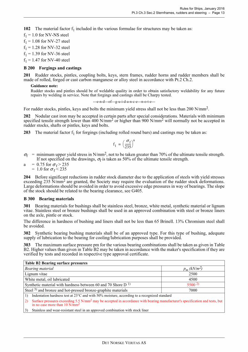
303 The maximum surface pressure pm for the various bearing combinations shall be taken as given in TableB2. Higher values than given in Table B2 may be taken in accordance with the maker's specification if they areverified by tests and recorded in respective type approval certificate.
Table B2 Bearing surface pressuresBearing material pm (kN/m2)Lignum vitae 2500White metal, oil lubricated 4500Synthetic material with hardness between 60 and 70 Shore D 1) 5500 2)
Steel 3) and bronze and hot-pressed bronze-graphite materials 70001) Indentation hardness test at 23°C and with 50% moisture, according to a recognized standard
2) Surface pressures exceeding 5.5 N/mm2 may be accepted in accordance with bearing manufacturer's specification and tests, but in no case more than 10 N/mm2
3) Stainless and wear-resistant steel in an approved combination with stock liner
f1
σ f
235---------
a=
DET NORSKE VERITAS AS
Rules for Ships, January 2016 Pt.3 Ch.3 Sec.2 Sternframes, rudders and steering – Page 14
B 400 Certification
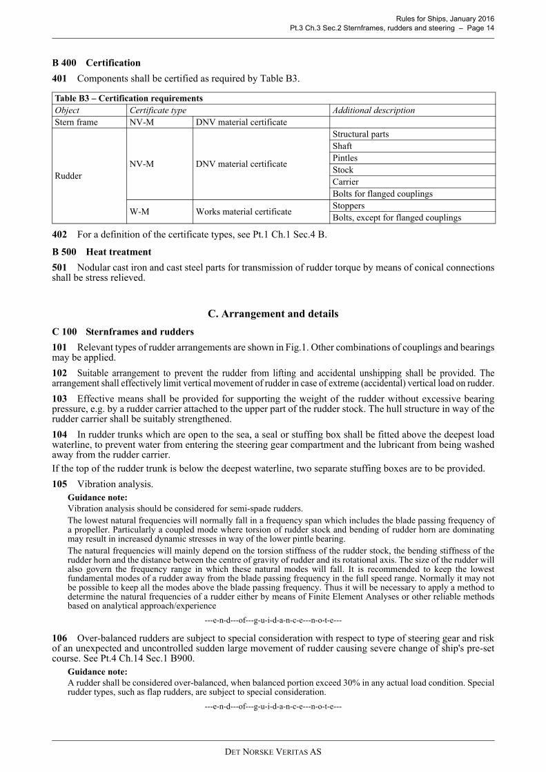
401 Components shall be certified as required by Table B3.
402 For a definition of the certificate types, see Pt.1 Ch.1 Sec.4 B.
B 500 Heat treatment
501 Nodular cast iron and cast steel parts for transmission of rudder torque by means of conical connectionsshall be stress relieved.
C. Arrangement and details
C 100 Sternframes and rudders
101 Relevant types of rudder arrangements are shown in Fig.1. Other combinations of couplings and bearingsmay be applied.
102 Suitable arrangement to prevent the rudder from lifting and accidental unshipping shall be provided. Thearrangement shall effectively limit vertical movement of rudder in case of extreme (accidental) vertical load on rudder.
103 Effective means shall be provided for supporting the weight of the rudder without excessive bearingpressure, e.g. by a rudder carrier attached to the upper part of the rudder stock. The hull structure in way of therudder carrier shall be suitably strengthened.
104 In rudder trunks which are open to the sea, a seal or stuffing box shall be fitted above the deepest loadwaterline, to prevent water from entering the steering gear compartment and the lubricant from being washedaway from the rudder carrier.If the top of the rudder trunk is below the deepest waterline, two separate stuffing boxes are to be provided.
105 Vibration analysis.Guidance note:Vibration analysis should be considered for semi-spade rudders.The lowest natural frequencies will normally fall in a frequency span which includes the blade passing frequency ofa propeller. Particularly a coupled mode where torsion of rudder stock and bending of rudder horn are dominatingmay result in increased dynamic stresses in way of the lower pintle bearing.The natural frequencies will mainly depend on the torsion stiffness of the rudder stock, the bending stiffness of therudder horn and the distance between the centre of gravity of rudder and its rotational axis. The size of the rudder willalso govern the frequency range in which these natural modes will fall. It is recommended to keep the lowestfundamental modes of a rudder away from the blade passing frequency in the full speed range. Normally it may notbe possible to keep all the modes above the blade passing frequency. Thus it will be necessary to apply a method todetermine the natural frequencies of a rudder either by means of Finite Element Analyses or other reliable methodsbased on analytical approach/experience
---e-n-d---of---g-u-i-d-a-n-c-e---n-o-t-e---
106 Over-balanced rudders are subject to special consideration with respect to type of steering gear and riskof an unexpected and uncontrolled sudden large movement of rudder causing severe change of ship's pre-setcourse. See Pt.4 Ch.14 Sec.1 B900.
Guidance note:A rudder shall be considered over-balanced, when balanced portion exceed 30% in any actual load condition. Specialrudder types, such as flap rudders, are subject to special consideration.
---e-n-d---of---g-u-i-d-a-n-c-e---n-o-t-e---
Table B3 – Certification requirementsObject Certificate type Additional descriptionStern frame NV-M DNV material certificate
Rudder NV-M DNV material certificate
Structural partsShaftPintlesStockCarrierBolts for flanged couplings
W-M Works material certificateStoppersBolts, except for flanged couplings
DET NORSKE VERITAS AS

Rules for Ships, January 2016 Pt.3 Ch.3 Sec.2 Sternframes, rudders and steering – Page 15
D. Design loads and stress analysis
D 100 Rudder force and rudder torque, general
101 The rudder force upon which the rudder scantlings shall be based shall be determined from the followingformula:
FR = 0.044 k1 k2 k3 A Vstr2 (kN)
A = area of rudder blade in m2, including area of flap.= vertical projected area of nozzle rudder
k1 = coefficient depending on rudder profile type (see Fig.2):
k2 = coefficient depending on rudder/nozzle arrangement= 1.0 in general= 0.8 for rudders which at no angle of helm work in the propeller slip stream= 1.15 for rudders behind a fixed propeller nozzle
k3 = not to be taken greater than 4
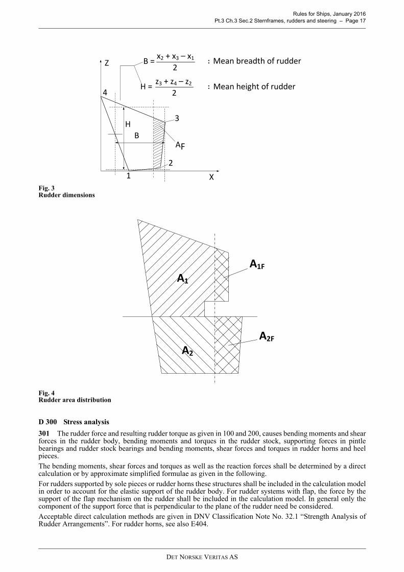
H = mean height in m of the rudder area. Mean height and mean breadth B of rudder area to be calculatedas shown in Fig.3
At = total area of rudder blade in m2 including area of flap and area of rudder post or rudder horn, if any,within the height H
Vstr = service speed as defined in A201.
When the speed is less than 10 knots, Vstr shall be replaced by the expression:
For the astern condition the maximum astern speed shall be used, however, in no case less than:Vastern = 0.5 Vstr or min. 5 knots
102 The rule rudder torque shall be calculated for both the ahead and astern condition according to theformula:
MTR = |FR · xe| (kNm)= minimum 0.1 FR B
FR = as given in 101 for ahead and astern conditionsxe = B (α − k) (m)B = mean breadth of rudder area, see Fig.3α = 0.33 for ahead condition
= 0.66 for astern condition (general)= 0.75 for astern condition (hollow profiles).
For flap rudders or other high lift rudders α will be specially considered. If not known, α = 0.40 may be usedfor ahead conditions
k =
AF = area in m2 of the portion of the rudder blade area situated ahead of the centre line of the rudder stock
Table D1 Rudder profile type - coefficientProfile type Ahead AsternNACA - Göttingen 1.10 0.80Hollow profile 1) 1.35 0.90Flatsided 1.10 0.90Profile with «fish tail» 1.40 0.80Rudder with flap 1.70 To be specially
considered. If not known: 1.30
Nozzle rudder 1.90 1.50Mixed profiles (e. g. HSVA) 1.21 0.901) Profile where the width somewhere along the length is 75% or less of the width of a
flat side profile with same nose radius and a straight line tangent to after end
H2
At------ 2+
Vmin
Vstr 20+
3----------------------=
AF
A-------
DET NORSKE VERITAS AS

Rules for Ships, January 2016 Pt.3 Ch.3 Sec.2 Sternframes, rudders and steering – Page 16
A = rudder blade area as given in 101.
For special rudder designs (such as flap rudders) direct calculations of rudder torque, supported by measurementson similar rudders, may be considered as basis for rudder torque estimation.
Fig. 2Rudder profiles
D 200 Rudders with stepped contours
201 The total rudder force FR shall be calculated according to 101, with height and area taken for the wholerudder.
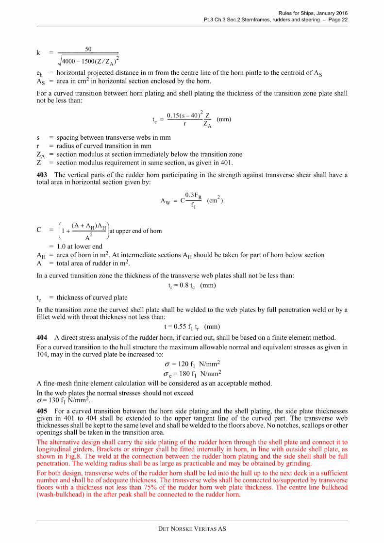
202 The pressure distribution over the rudder area may be determined by dividing the rudder into relevantrectangular or trapezoidal areas, see e.g. Fig.4. The rule rudder torque may be determined by:
= minimum 0.1 FR xem
n = number of partsi = integer
F Ri =
x ei = Bi (α - ki)
x em=
Ai = partial area in m2
Bi = mean breadth of part area, see Fig.3α = as given in 102
For parts of a rudder behind a fixed structure such as a rudder horn:α = 0.25 for ahead condition = 0.55 for astern condition
ki =
A iF = rudder part area forward of rudder stock centre line, see Fig.4
FR and A as given in 101.
MTR FRixei( ) (kNm)
i 1=
n
=
Ai
A-----FR
AiBi( )A
----------------
i 1=
n
AiF
Ai--------
DET NORSKE VERITAS AS
Rules for Ships, January 2016 Pt.3 Ch.3 Sec.2 Sternframes, rudders and steering – Page 17
Fig. 3Rudder dimensions
Fig. 4Rudder area distribution
D 300 Stress analysis
301 The rudder force and resulting rudder torque as given in 100 and 200, causes bending moments and shearforces in the rudder body, bending moments and torques in the rudder stock, supporting forces in pintlebearings and rudder stock bearings and bending moments, shear forces and torques in rudder horns and heelpieces.The bending moments, shear forces and torques as well as the reaction forces shall be determined by a directcalculation or by approximate simplified formulae as given in the following.For rudders supported by sole pieces or rudder horns these structures shall be included in the calculation modelin order to account for the elastic support of the rudder body. For rudder systems with flap, the force by thesupport of the flap mechanism on the rudder shall be included in the calculation model. In general only thecomponent of the support force that is perpendicular to the plane of the rudder need be considered.Acceptable direct calculation methods are given in DNV Classification Note No. 32.1 “Strength Analysis ofRudder Arrangements”. For rudder horns, see also E404.
X
Z
AF
3H
B
21
:
:
B =
H =4
2
2
Mean breadth of rudder
Mean height of rudder
x2 + x3 – x1
z3 + z4 – z2
A1
A2
A1F
A2F
DET NORSKE VERITAS AS

Rules for Ships, January 2016 Pt.3 Ch.3 Sec.2 Sternframes, rudders and steering – Page 18
302 Allowable stresses for the various strength members are given in subsections E to J.For evaluation of angular deflections, see B204, G201 and G405.
E. Sternframes, sole pieces, rudder horns, and rudder trunks
E 100 General
101 Sternframes and rudder horns shall be effectively attached to the surrounding hull structures. Inparticular the stern bearing or vertical coupling flange for rudder axle shall be appropriately attached to thetransom floor adjacent to the rudder stock.For semi-spade and spade rudder arrangements structural continuity in the transverse as well as the longitudinaldirection shall be specially observed.
102 Cast steel sternframes and welded sternframes shall be strengthened by transverse webs.Castings shall be of simple design, and sudden changes of section shall be avoided. Where shell plating, floorsor other structural parts are welded to the sternframe, there shall be a gradual thickness reduction towards thejoint.
103 Depending on casting facilities, larger cast steel propeller posts shall be made in two or more pieces.Sufficient strength shall be maintained at connections. The plates of welded propeller posts may be welded toa suitable steel bar at the after end of the propeller post.
104 Stresses determined by direct calculations as indicated in D300 are normally not to exceed the followingvalues:
— Normal stress: σ = 80 f1 (N/mm2)— Shear stress: τ = 50 f1 (N/mm2)— Equivalent stress: σ e = 120 f1 (N/mm2)
E 200 Propeller posts
201 The boss thickness at the bore for the stern tube shall not be less than:
d = diameter of propeller shaft in mm.
202 The scantlings of fabricated propeller posts shall not be less than:
l, b and t are as shown in Fig.5 Alt. I.Where the section adopted differs from the above, the section modulus about the longitudinal axis shall not beless than:
203 The scantlings of cast steel propeller posts shall not be less than:
σe σ12 σ2
2 σ1σ2– 3τ2+ +=
t 5 dp 60– (mm)=
l 53 L (mm)=
b 37 L (mm)=
t2.4 L
f1
---------------- (mm)=
ZW1.35L L
f1----------------------- (cm
3 )=
l 40 L (mm)=
b 30 L (mm)=
t13 L
f1
----------- (mm)=
DET NORSKE VERITAS AS

Rules for Ships, January 2016 Pt.3 Ch.3 Sec.2 Sternframes, rudders and steering – Page 19
l, b, t1 and t2 are as shown in Fig.5 Alt. II.Where the section adopted differs from the above, the section modulus about the longitudinal axis shall not beless than:
When calculating the section modulus, adjoining shell plates within a width equal to 53 from the after endof the post may be included.
Fig. 5Propeller posts
E 300 Sole pieces
301 The sole piece shall be sloped in order to avoid pressure from keel blocks when docking. The sole pieceshall extend forward of the after edge of the propeller boss, for sufficient number of frame spaces to provideadequate fixation at the connection with deep floors of the aft ship structure. The cross section of this extendedpart may be gradually reduced to the cross section necessary for an efficient connection to the plate keel.
302 The section modulus requirement of the sole piece about a vertical axis abaft the forward edge of thepropeller post is given by:
ls = distance in m from the centre line of the rudder stock to the section in question. ls shall not be taken lessthan half the free length of the sole piece.
303 If direct stress analysis is carried out, the nominal bending stress in the sole piece shall not exceed:σ = 115 f1
304 The section modulus of the sole piece about a horizontal axis abaft the forward edge of the propeller postshall not be to be less than:
t23.7 L
f1
---------------- (mm)=
ZC1.3L L
f1-------------------- (cm
3 )=
L
Z1
6.25FRls
f1---------------------- (cm
3 )=
Z2
Z1
2------ (cm
3 )=
DET NORSKE VERITAS AS

Rules for Ships, January 2016 Pt.3 Ch.3 Sec.2 Sternframes, rudders and steering – Page 20
305 The sectional area of the sole piece shall not be less than:
E 400 Rudder horns
401 The section modulus requirement of the rudder horn about a longitudinal axis is given by:
lh = vertical distance in m from the middle of the horn pintle bearing to the section in questionyh = vertical distance in m from the middle of the rule pintle bearing to the middle of the neck bearingF Ri = part of rudder force acting on the i-th part of the rudder area, see D202y ei = vertical distance in m from the centroid of the i-th part of the rudder area to the middle of the neck
bearingn = number of rudder parts
For the straight part of the rudder horn the section modulus may be taken for the total sectional area of the horn.When the connection between the rudder horn and the hull structure is designed as a curved transition into thehull plating the section modulus requirement as given above shall be satisfied by the transverse web plates asfollows:
n = number of transverse websbi = effective breadth in mm of web no. i. (including the flange thickness)ti = thickness in mm of web no. ibmax = largest bi.
Z, bi and bmax shall be taken at a horizontal section 0.7 r above the point where the curved transition starts (r =radius of curved part, see Fig.6).The formula for ZW is based on the material in web plates and shell plate being of the same strength.For a cast rudder horn any vertical extension of the side plating (see Fig.7) may be included in the sectionmodulus.
AS
0.1FR
f1--------------- (cm
2 )=
Z15MVlh
yhf1-------------------- (cm
3 )=
MV FRiyei
i 1=
n
=
ZW
bi3ti
i 1=
n
6000bmax------------------------ 0.45Z≥=
DET NORSKE VERITAS AS

Rules for Ships, January 2016 Pt.3 Ch.3 Sec.2 Sternframes, rudders and steering – Page 21
Fig. 6Curved plate transition rudder horn/shell plating
Fig. 7Curved cast transition rudder horn/shell plating
402 The rudder horn thickness shall not be less than the greater of:
and
1f
L4.2=t [mm]
t110kFReh
f1AS------------------------- (mm)=
DET NORSKE VERITAS AS
Rules for Ships, January 2016 Pt.3 Ch.3 Sec.2 Sternframes, rudders and steering – Page 22
k =
eh = horizontal projected distance in m from the centre line of the horn pintle to the centroid of ASAS = area in cm2 in horizontal section enclosed by the horn.
For a curved transition between horn plating and shell plating the thickness of the transition zone plate shallnot be less than:
s = spacing between transverse webs in mmr = radius of curved transition in mmZA = section modulus at section immediately below the transition zoneZ = section modulus requirement in same section, as given in 401.
403 The vertical parts of the rudder horn participating in the strength against transverse shear shall have atotal area in horizontal section given by:
C =
= 1.0 at lower endAH = area of horn in m2. At intermediate sections AH should be taken for part of horn below sectionA = total area of rudder in m2.
In a curved transition zone the thickness of the transverse web plates shall not be less than:tr = 0.8 tc (mm)
tc = thickness of curved plate
In the transition zone the curved shell plate shall be welded to the web plates by full penetration weld or by afillet weld with throat thickness not less than:
t = 0.55 f1 tr (mm)
404 A direct stress analysis of the rudder horn, if carried out, shall be based on a finite element method.For a curved transition to the hull structure the maximum allowable normal and equivalent stresses as given in104, may in the curved plate be increased to:
σ = 120 f1 N/mm2
σ e = 180 f1 N/mm2
A fine-mesh finite element calculation will be considered as an acceptable method.In the web plates the normal stresses should not exceed σ = 130 f1 N/mm2.
405 For a curved transition between the horn side plating and the shell plating, the side plate thicknessesgiven in 401 to 404 shall be extended to the upper tangent line of the curved part. The transverse webthicknesses shall be kept to the same level and shall be welded to the floors above. No notches, scallops or otheropenings shall be taken in the transition area.The alternative design shall carry the side plating of the rudder horn through the shell plate and connect it tolongitudinal girders. Brackets or stringer shall be fitted internally in horn, in line with outside shell plate, asshown in Fig.8. The weld at the connection between the rudder horn plating and the side shell shall be fullpenetration. The welding radius shall be as large as practicable and may be obtained by grinding.For both design, transverse webs of the rudder horn shall be led into the hull up to the next deck in a sufficientnumber and shall be of adequate thickness. The transverse webs shall be connected to/supported by transversefloors with a thickness not less than 75% of the rudder horn web plate thickness. The centre line bulkhead(wash-bulkhead) in the after peak shall be connected to the rudder horn.
50
4000 1500 Z ZA⁄( )2–
---------------------------------------------------------
tc0.15 s 40–( )2
r--------------------------------- Z
ZA------- (mm)=
AW C0.3FR
f1--------------- (cm
2 )=
1A AH+( )AH
A2
--------------------------------+
at upper end of horn
DET NORSKE VERITAS AS
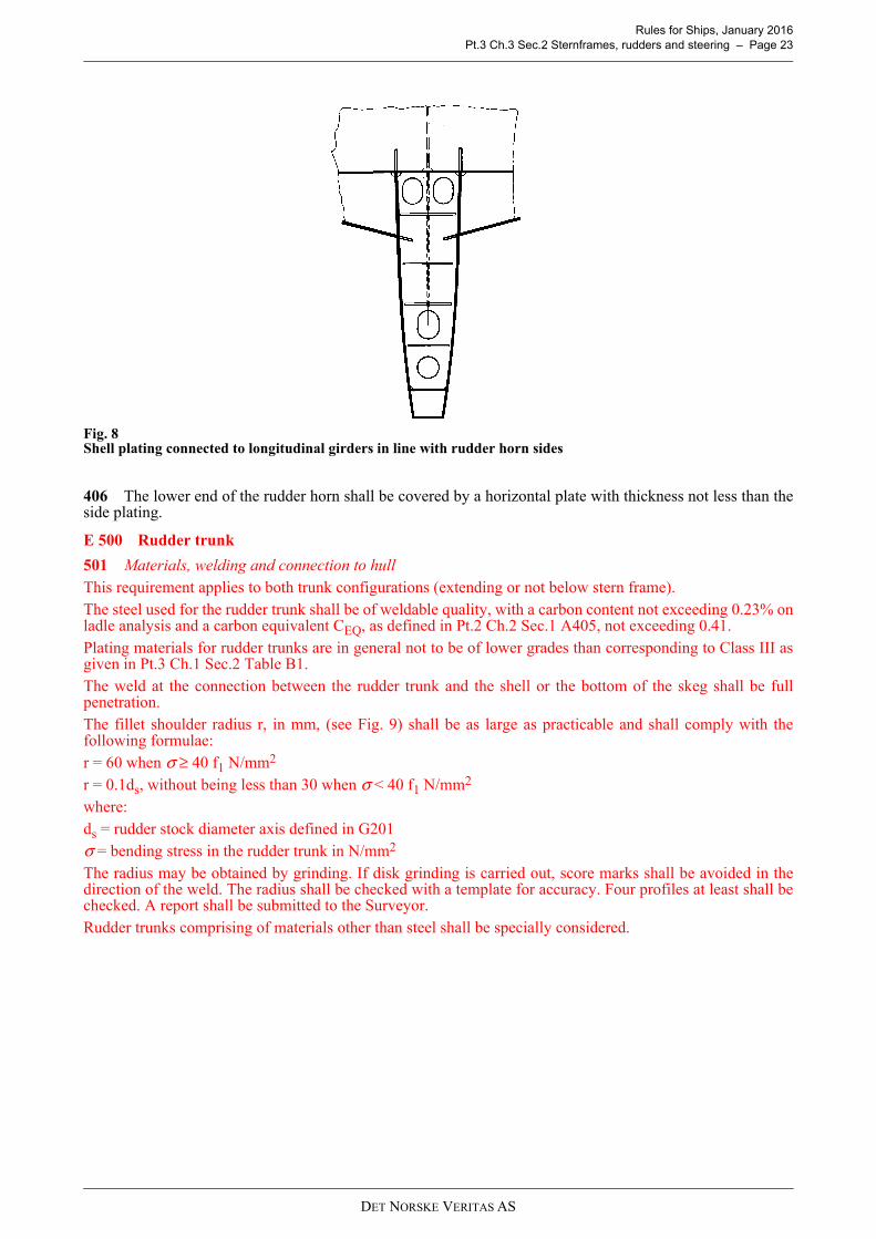
Rules for Ships, January 2016 Pt.3 Ch.3 Sec.2 Sternframes, rudders and steering – Page 23
Fig. 8Shell plating connected to longitudinal girders in line with rudder horn sides
406 The lower end of the rudder horn shall be covered by a horizontal plate with thickness not less than theside plating.
E 500 Rudder trunk
501 Materials, welding and connection to hull This requirement applies to both trunk configurations (extending or not below stern frame).The steel used for the rudder trunk shall be of weldable quality, with a carbon content not exceeding 0.23% onladle analysis and a carbon equivalent CEQ, as defined in Pt.2 Ch.2 Sec.1 A405, not exceeding 0.41.Plating materials for rudder trunks are in general not to be of lower grades than corresponding to Class III asgiven in Pt.3 Ch.1 Sec.2 Table B1.The weld at the connection between the rudder trunk and the shell or the bottom of the skeg shall be fullpenetration.The fillet shoulder radius r, in mm, (see Fig. 9) shall be as large as practicable and shall comply with thefollowing formulae:r = 60 when σ ≥ 40 f1 N/mm2
r = 0.1ds, without being less than 30 when σ < 40 f1 N/mm2
where:ds = rudder stock diameter axis defined in G201σ = bending stress in the rudder trunk in N/mm2
The radius may be obtained by grinding. If disk grinding is carried out, score marks shall be avoided in thedirection of the weld. The radius shall be checked with a template for accuracy. Four profiles at least shall bechecked. A report shall be submitted to the Surveyor.Rudder trunks comprising of materials other than steel shall be specially considered.
DET NORSKE VERITAS AS

Rules for Ships, January 2016 Pt.3 Ch.3 Sec.2 Sternframes, rudders and steering – Page 24
Fig. 9Fillet shoulder radius
502 ScantlingsWhere the rudder stock is arranged in a trunk in such a way that the trunk is stressed by forces due to rudderaction, the scantlings of the trunk are to be such that:
— the equivalent stress due to bending and shear does not exceed 0.35 σf,— the bending stress on welded rudder trunk is to be in compliance with the following formula:
σ ≤ 80f1 N/mm²σ = bending stress in the rudder trunk in N/mm2.σf = yield stress in N/mm2 of the material usedFor calculation of bending stress, the span to be considered is the distance between the mid-height of the lowerrudder stock bearing and the point where the trunk is clamped into the shell or the bottom of the skeg.
F. Rudders
F 100 General arrangement and details
101 Rudders shall be double plate type with internal vertical and horizontal web plates.The rudder body shall be stiffened by horizontal and vertical webs enabling it to act as a girder in bending.Single plate rudders may be applied to smaller vessels of special design and with service restrictions, see 600.
102 All rudder bearings shall be accessible for measuring of wear without lifting or unshipping the rudder.Guidance note:In case cover plates are permanently welded to the side plating, it is recommended to arrange peep holes for inspectionof securing of nuts and pintles.
---e-n-d---of---g-u-i-d-a-n-c-e---n-o-t-e---
103 The following detail requirements apply to semi-spade rudders in way of the rudder horn recess:
— the radii in the rudder plating in way of the recess shall not be less than 5 times the plate thickness, but inno case less than 100 mm
— welding in side plate shall be avoided in or at the end of the radii— edges of side plate and weld adjacent to radii shall be ground smooth.
Guidance note:Edge preparation and the performance of coating are of importance for the fatigue life of the rudder.
---e-n-d---of---g-u-i-d-a-n-c-e---n-o-t-e---
Radius to be considered
Radius to be considered
DET NORSKE VERITAS AS

Rules for Ships, January 2016 Pt.3 Ch.3 Sec.2 Sternframes, rudders and steering – Page 25
104 Plate edges at openings in rudder side plating shall be ground smooth. Cover plates shall be arranged withrounded corners and are not to be welded directly to cast parts.
105 Means for draining the rudder completely after pressure testing or possible leakages shall be provided.Drain plugs shall be fitted with efficient packing.
F 200 Rudder plating
201 The thickness requirement of side, top and bottom plating is given by:
ka =
maximum 1.0s = the smaller of the distances between the horizontal or the vertical web plates in mb = the larger of the distances between the horizontal or the vertical web plates in m.
In no case the thickness shall be less than the minimum side plate thickness as given in Ch.1 Sec.7 C101 orCh.2 Sec.6 C102.
F 300 Rudder bending
301 Bending moments in the rudder shall be determined by direct calculations as indicated in D300.For some common rudder types the following approximate formulae may be applied:
— For balanced rudders with heel support:Mmax = 0.125 FR H (kNm)
— For semi-spade rudders at the horn pintle:
— For spade rudders:
A1 = area in m2 of the rudder part below the cross-section in questionhs = vertical distance in m from the centroid of the rudder area A1 to the section in question.
302 The nominal bending stress distribution in the rudder may normally be determined on the basis of aneffective section modulus to be estimated for side plating and web plates within 40% of the net length (cut-outsor openings deducted) of the rudder profile. At the top of the rudder, the actual section modulus of the cross-section of the structure of the rudder bladewhich is connected with the solid part where the rudder stock is housed is to be calculated with respect to thesymmetrical axis of the rudder.The breadth of the rudder plating to be considered for the calculation of this actual section modulus is to be notgreater than that obtained from the following formula:
sV = Spacing between the two vertical webs [m]m = Coefficient to be taken, in general, equal to 3.Hx = Vertical distance between the considered section and the upper end of the solid part.Where openings for access to the rudder stock nut are not closed by a full penetration welded plate, they shallbe deducted.
t5.5
f1
--------kas T0.1FR
A---------------+ 2.5 (mm)+=
1.1 0– .5sb--- 2
MFRA1hs
A------------------- (kNm)=
Mmax
FRA1hs
A------------------- (kNm)=
mHsb x
v 2+= [m]
DET NORSKE VERITAS AS

Rules for Ships, January 2016 Pt.3 Ch.3 Sec.2 Sternframes, rudders and steering – Page 26
Fig. 10Cross-section of the connection between rudder blade structure and rudder stock housing
Special attention to be paid to open flange couplings on the rudder. The external transverse brackets willnormally have to be supplied with heavy flanges to obtain the necessary section modulus of the rudderimmediately below the flange.As an alternative the bending stress distribution in the rudder may be determined by a finite elementcalculation.
303 Nominal bending stresses calculated as given in 301 and 302 shall not exceed:
σ = 110 f1 N/mm2 in general= 75 N/mm2 in way of the recess for the rudder horn pintle on semi-spade rudders.
In case of openings in side plate for access to cone coupling or pintle nut, σ = 90 f1 (N/mm2) to be applied whenthe corner radius is greater than 0.15 l (l = length of opening), σ = 60 f1 (N/mm2) when the radius is smaller.
F 400 Web plates
401 The thickness of vertical and horizontal webs shall not be less than 70% of the thickness requirementgiven in 200, in no case less than 8 mm.
402 The total web area requirement for the vertical webs is given by:
P =
with heel support
= for spade rudder or lower part of semi-spade rudder
AWP
5f1------- (cm
2 )=
0.6h1
H-----–
FR for balanced rudder
h2
H-----FR
DET NORSKE VERITAS AS

Rules for Ships, January 2016 Pt.3 Ch.3 Sec.2 Sternframes, rudders and steering – Page 27
h1 = height in m of the smaller of rudder parts below or above the cross-section in questionh2 = height in m of the rudder part below the cross section in question.
Shear stresses in web plates determined by direct stress calculations shall not exceed:τ = 50 f1 (N/mm2)
Equivalent stress shall not exceed:
σe =
= 120 f1 N/mm2 in rudder-blades without cut-outs= 100 f1 N/mm2 in rudder-blades with cut-outs.
F 500 Connections of rudder blade structure with solid parts
501 Solid parts in forged or cast steel, which house the rudder stock or the pintle, are normally to be providedwith protrusions. These protrusions are not required when the web plate thickness is less than:
— 10 mm for web plates welded to the solid part on which the lower pintle of a semi-spade rudder is housedand for vertical web plates welded to the solid part of the rudder stock coupling of spade rudders
— 20 mm for other web plates.
502 The solid parts are in general to be connected to the rudder structure by means of two horizontal webplates and two vertical web plates.
503 Minimum section modulus of the connection with the rudder stock housingThe section modulus of the cross-section of the structure of the rudder blade, in cm3, formed by vertical webplates and rudder plating, which is connected with the solid part where the rudder stock is housed shall not beless than:
where:
The actual section modulus of the cross-section of the structure of the rudder blade shall be calculated withrespect to the symmetrical axis of the rudder.The breadth of the rudder plating, in m, considered for the calculation of section modulus shall be as per 302.
504 The thickness of the horizontal web plates connected to the solid parts, in mm, as well as that of therudder blade plating between these webs, shall not be less than the greater of the following values: tH = 1.2 t [mm]tH = 0.045 d2 / sH [mm]where:
The increased thickness of the horizontal webs is to extend fore and aft of the solid part at least to the nextvertical web.
cS = coefficient, to be taken equal to: = 1.0 if there is no opening in the rudder plating or if such openings are closed by a full penetration
welded plate= 1.5 if there is an opening in the considered cross-section of the rudder
ds = rudder stock diameter, in mmHE = vertical distance between the lower edge of the rudder blade and the upper edge of the solid part, in mHX = vertical distance between the considered cross-section and the upper edge of the solid part, in mf1b = material factor for the rudder blade platingf1s = material factor for the rudder stock
t = required thickness of the rudder plating, in mm, as defined in 201d = diameter, in mm, to be taken equal to:
= ds, as per G201, for the solid part housing the rudder stock= dp, as per G403, for the solid part housing the pintle
sH = spacing between the two horizontal web plates, in [mm]
σb2
3τ2+
= 3 − 2 10−4
DET NORSKE VERITAS AS

Rules for Ships, January 2016 Pt.3 Ch.3 Sec.2 Sternframes, rudders and steering – Page 28
505 The thickness of the vertical web plates welded to the solid part where the rudder stock is housed as wellas the thickness of the rudder side plating under this solid part shall not be less than the values obtained, in mm,from the following table.
The increased thickness shall extend below the solid piece at least to the next horizontal web.
F 600 Single plate rudders
601 Mainpiece diameterThe mainpiece diameter is calculated according to G201. For spade rudders the lower third may taper down to0.75 times stock diameter.When calculating the rudder force FR as given in D101 the factor k1 is to be taken equal to 1.0 for both theahead and the astern condition.
602 Blade thicknessThe blade thickness shall not be less than:
s = spacing of stiffening arms in metres, not to exceed 1 mV = speed in knots, see D101.
603 ArmsThe thickness of the arms shall not be less than the blade thickness:
ta = tbThe section modulus shall not be less than:
C1 = horizontal distance from the aft edge of the rudder to the centre line of the rudder stock in metres.
G. Rudder stocks and shafts
G 100 General
101 Stresses determined by direct calculations as indicated in D300 are normally to give equivalent stress σenot exceeding 118 f1 N/mm2 and shear stress τ not exceeding 68 f1 N/mm2. The equivalent stress for axles incombined bending and torsion may be taken as:
σ = bending stress in N/mm2
τ = torsional stress in N/mm2.
102 The requirements to diameters are applicable regardless of liner. Both ahead and astern conditions shallbe considered.
103 A rudder stock cone coupling connection without hydraulic arrangement for mounting and dismountingshall not be applied for spade rudders.
104 An effective sealing shall be provided at each end of the cone coupling.
Type of rudderThickness of vertical web plates, in mm Thickness of rudder plating, in mm
Rudder blade without opening
Rudder blade with opening
Rudder blade without opening
Area with opening
Rudder supported by sole piece 1.2 t 1.6 t 1.2 t 1.4 t
Semi-spade and spade rudders 1.4 t 2.0 t 1.3 t 1.6 tt = required thickness of the rudder plating, in mm, as defined in 201
5.2+f
sV5.1=t
1b (mm)
1
221
a f
VsC5.0=Z (cm3)
σe σ23τ2
+ (N/mm2 )=
DET NORSKE VERITAS AS
Rules for Ships, January 2016 Pt.3 Ch.3 Sec.2 Sternframes, rudders and steering – Page 29
G 200 Rudder stock with couplings
201 The diameter requirement is given by:
kb = 1 above the rudder carrier, except where the rudder stock is subjected to bending moment induced bythe rudder actuator (bearing arrangement versus rudder stock bending deflections, or actuator forcesacting on tiller)
=
MB = calculated bending moment in kNm at the section in question.
MB = FR · hs (kNm) - at neck bearing for spade rudder.For other rudder types MB may generally be based on direct calculation of bending moment distribution. Atneck bearing for semi-spade rudder MB is not to be taken less than 0.5 MB as given in formula below.If direct calculations of bending moment distribution are not carried out, MB at the neck bearing or the ruddercoupling may be taken as follows:
— for balanced rudder with heel support:
— for semi-spade rudder:
hs = vertical distance in m from the centroid of the rudder area to the middle of the neck bearing or thecoupling.
For rudders where the neck bearing is mounted on a trunk extending into the rudder, hs is not to be taken lessthan H/6.At the bearing above neck bearing MB = 0, except as follows:
— for rotary vane type actuators with two rotor bearings, which allow only small free deflections, calculationof bending moment influence may be required if bending deflection in way of upper bearing, for the designrudder force FR, exceeds two times the diametrical bearing clearances. In lieu of a direct calculation, thedeflection of the rudder stock between the rotor bearings, δub may be taken equal to:
Ia = moment of inertia of rudder stock in cm4
l = la - hf for arrangements with upper pintle bearingl = la for arrangements with neck bearingla = distance in m from mid-height of neck bearing or upper pintle bearing, as applicable, to mid-height
of upper stock bearinghf = distance in m from upper end of rudder to mid-height neck bearinghub= centre distance of the rotor bearings in mm
— for actuator force induced bending moment the greater of the following:M BU = Fdes hA (kNm)
orM BU = FMTR hA (kNm)
hA = vertical distance between force and bearing centreFMTR= according to Pt.4 Ch.14 Sec.1 B1121M BU= bending moment at bearing above neck bearingFdes = radial force induced by actuator at design pressure.
Minimum diameter of the rudder stock between the neck and the bearing above shall not be less than if taperedwith kb=1.0 at the second bearing.
ds 42kb
MTR
f1------------
13---
(mm)=
143---
MB
MTR------------
2+
16---
at arbitrary cross-section
MB
FRH
7----------- (kNm)=
MB
FRH
17----------- (kNm)=
δub
105l hub MB
6 E Ia---------------------------- (mm)=
DET NORSKE VERITAS AS
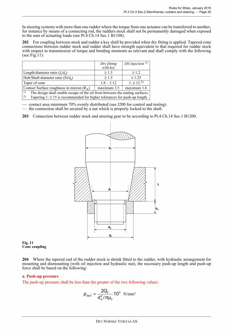
Rules for Ships, January 2016 Pt.3 Ch.3 Sec.2 Sternframes, rudders and steering – Page 30
In steering systems with more than one rudder where the torque from one actuator can be transferred to another,for instance by means of a connecting rod, the rudders stock shall not be permanently damaged when exposedto the sum of actuating loads (see Pt.4 Ch.14 Sec.1 B1108).
202 For coupling between stock and rudder a key shall be provided when dry fitting is applied. Tapered coneconnections between rudder stock and rudder shall have strength equivalent to that required for rudder stockwith respect to transmission of torque and bending moments as relevant and shall comply with the following(see Fig.11):
— contact area minimum 70% evenly distributed (see J200 for control and testing)— the connection shall be secured by a nut which is properly locked to the shaft.
203 Connection between rudder stock and steering gear to be according to Pt.4 Ch.14 Sec.1 B1200.
Fig. 11Cone coupling
204 Where the tapered end of the rudder stock is shrink fitted to the rudder, with hydraulic arrangement formounting and dismounting (with oil injection and hydraulic nut), the necessary push-up length and push-upforce shall be based on the following:
a. Push-up pressureThe push-up pressure shall be less than the greater of the two following values:
Dry fittingwith key
Oil injection 1)
Length/diameter ratio (lt/ds) ≥ 1.5 ≥ 1.2Hub/Shaft diameter ratio (D/ds) ≥ 1.5 ≥ 1.25Taper of cone 1:8 – 1:12 1: ≥ 12 2)
Contact Surface roughness in micron (RA) maximum 3.5 maximum 1.61) The design shall enable escape of the oil from between the mating surfaces.2) Tapering 1: ≥ 15 is recommended for higher tolerances for push-up length.
dn
dg
dt
lt
hn
ds
3
021 102
πμdQp
m
Freq
= N/mm²
DET NORSKE VERITAS AS

Rules for Ships, January 2016 Pt.3 Ch.3 Sec.2 Sternframes, rudders and steering – Page 31
where:
It shall be proven by the designer that the push-up pressure does not exceed the permissible surface pressure inthe cone. The permissible surface pressure, in N/mm², shall be determined by the following formula:
where:
b. Push-up lengthThe push-up length Δ, in mm, is to comply with the following formula:
where:
Notwithstanding the above, the push-up length shall not be less than 2 mm.
c. Push-up forceGuidance note:In case of hydraulic pressure connections the required push-up force Pe, in N, for the cone may be determined by thefollowing formula:
The value 0.02 is a reference for the friction coefficient using oil pressure. It varies and depends on the mechanicaltreatment and roughness of the details to be fixed. Where due to the fitting procedure a partial push-up effect causedby the rudder weight is given, this may be taken into account when fixing the required push-up length, subject toapproval by the Society.
---e-n-d---of---g-u-i-d-a-n-c-e---n-o-t-e---
QF = design yield moment of rudder stock, as defined in 205, in Nmdm = mean cone diameter in mm = cone length in [mm]µ0 = frictional coefficient, equal to 0.15Mb = bending moment in the cone coupling (e.g. in case of spade rudders), in kNm
ReH = minimum yield stress of the material of the gudgeon in N/mm2
α = dm /dadm = diameter, in mmda = outer diameter of the gudgeon to be not less than 1.5 dm, in mm
Rtm = mean roughness, in [mm] taken equal to 0.01 c = taper of cone according to 202
6
m2
b2req 10
d
M6=p
N/mm²
( )4
2
3
18.0
ααRp eH
perm+
−= N/mm²
21 ∆∆∆ ≤≤
cR
cαE
dp tmmreq 8.0
2
1∆
21 +
=
- mm
cR
αEcdR tmmeH 8.0
3
6.1∆
42 ++
= mm
02.0
2+= cπdpP mreqe
DET NORSKE VERITAS AS

Rules for Ships, January 2016 Pt.3 Ch.3 Sec.2 Sternframes, rudders and steering – Page 32
205 Tapered key-fitted (keyed) connections shall be designed to transmit rudder torque in all normaloperating conditions by means of friction in order to avoid mutual movements between rudder stock and hub.The key shall be regarded as a securing device.For calculation of required push-up length (δ ), see 204 a), b) and e) where pr is given with Tfr = 1.5 MTR.Where it is not possible or practicable to obtain the required push-up length (δ ), special attention shall be givento fitting of the key in order to ensure tight fit (no free sideways play between key and key-way). In this caseTfr may be taken as Tfr = 0.5 MTR.Tapered key-fitted connections shall in addition comply with the following:
a) Key-ways shall not be placed in areas with high bending stresses in the rudder stock and shall be providedwith sufficient fillet radii (r):
r ≥ 0.01 ds
b) For couplings between stock and rudder a key shall be provided, the shear area of which, in cm2, shall notbe less than:
where:QF = design yield moment of rudder stock, in Nm QF = 0.02664dt
3f1Where the actual diameter dta is greater than the calculated diameter dt, the diameter dta shall be used.However, dta applied to the above formula need not be taken greater than 1.145 dt.
The effective surface area, in cm2, of the key (without rounded edges) between key and rudder stock orcone coupling shall not be less than:
where:σF2 = minimum yield stress of the key, stock or coupling material, in N/mm2, whichever is less.
c) The height/width ratio of the key shall be:
h = height (thickness) of the keyb = width of the key.
Where necessary tapered connections shall be provided with suitable means (e.g. oil grooves and bores toconnect hydraulic injection oil pump) to facilitate dismantling of the hub.The dimensions at the slugging nut shall not be less than (see Fig.11):
— external thread diameter:dg = 0.65 ds
— height of nut:hn = 0.6 dg
— outer diameter of nut:dn = 1.2 dt or dn = 1.5 dg whichever is the greater.
206 Where the rudder stock is connected to the rudder by horizontal flange coupling the followingrequirements shall be complied with:
a) At least 6 tight fitted coupling bolts shall be used.b) The shear diameter of coupling bolts shall not be less than:
dt = stock diameter required for transfer of torque, in mm. To be calculated according to G201 with kb =1.dk = mean diameter of the conical part of the rudder stock, in mm, at the keyσF1 = minimum yield stress of the key material, in N/mm2
1Fk
Fs σd
Q55.17=a
2Fk
Fk σd
Q5=a
hb--- 0.6≤
db 0.62ds
3fms
n e fmb---------------- (mm)=
DET NORSKE VERITAS AS

Rules for Ships, January 2016 Pt.3 Ch.3 Sec.2 Sternframes, rudders and steering – Page 33
ds = rule diameter as given in 201 for the rudder stock at coupling flange.For rudder stocks with a slanted lower part, ds shall be determined with MTR = MTRf, where MTRfis given as: MTRf = MTR + yl MB/l, where MB denotes the bending moment of the stock at thecoupling flange according to 201, l denotes the vertical distance from the upper bearing to the flangeattachment to the rudder, and yl denotes the longitudinal distance, if any, from the rudder axis to thecentre of the coupling bolt system
n = number of coupling boltse = mean distance in mm from the centre of bolts to the centre of the bolt systemf ms = material factor (f1) for rudder stockf mb = material factor (f1) for bolts.
c) Nuts and bolts shall be securely fastened by split pins or other efficient means.d) If the coupling is subjected to bending stresses, the mean distance a from the centre of the bolts to the
longitudinal centre line of the coupling shall not be less than 0.6 ds.Further, bolt pre-stress in shear part of bolt shall normally be in the range of 60 fmb to 120 fmb. In theminimum section of the bolt, pre-stress shall not exceed 165 fmb.
e) The width of material outside the bolt holes shall not be less than 0.67 db.f) The thickness of coupling flanges shall not be less than:
at the root section, however, not less than 0.25ds. Away from the root section the flange thickness may beevenly tapered down to 0.25 ds in way of the clamping bolts.
f mf = material factor (f1) for flange,MB = bending moment in kNm at couplinga = mean distance from centre of bolts to the longitudinal centre line of the coupling, in mmd = diameter as built of rudder stock for stock flange, breadth of rudder for rudder flange, both in mmβ = factor to be taken from the following table:
β shall not be taken less than 0.25 when d/a is greater than 1.6.kr is determined according to the following table:
kf = rf /(a – 0.5d)rf = radius of fillet, not to be taken less than 0.3·(a – 0.5d).
Guidance note:The mean distance from centre of bolts to the longitudinal centreline of the coupling, a, may in general be taken as:
The mean distance, e, from the centre of bolts to the centre of the bolt system may in general be taken as:
n = number of bolts.yi = distance from the longitudinal centreline of the rudder to the centre of bolt i.
d/a 0.8 0.9 1.0 1.1 1.2 1.3 1.4 1.5 1.6β 1.8 1.5 1.25 1.0 0.8 0.6 0.45 0.35 0.25
Table of krkf 0.5 0.4 0.3kr 70 75 84
t kr
β MB
a fmf------------ (mm)=
n
ya n
i=
( )
n
yxxe n
ioi +−=
22
n
xx n
i
o
=
DET NORSKE VERITAS AS

Rules for Ships, January 2016 Pt.3 Ch.3 Sec.2 Sternframes, rudders and steering – Page 34
xi = longitudinal distance from, e.g. the rudder axis to the centre of bolt i.
---e-n-d---of---g-u-i-d-a-n-c-e---n-o-t-e---
Fig. 12Rudder stock / flange
207 The welded joint between the rudder stock and the flange shall be made in accordance with Fig.13 orequivalent.
Fig. 13Welded joint between rudder stock and coupling flange
DET NORSKE VERITAS AS

Rules for Ships, January 2016 Pt.3 Ch.3 Sec.2 Sternframes, rudders and steering – Page 35
G 300 Rudder shaft
301 At the lower bearing, the rudder shaft diameter shall not be less than:
c =
l, a and b are given in Fig.14 in m.The diameter df below the coupling flange shall be 10% greater than dl. If, however, the rudder shaft isprotected by a corrosion-resistant composition above the upper bearing, df may be equal to dl.
302 The taper, nut, etc. at lower end of rudder shafts, shall be taken as for rudder stock given in 202.
303 The scantlings of the vertical coupling at the upper end of the rudder shaft shall be as required forhorizontal rudder couplings in 206, inserting the shaft dl instead of the stock diameter ds in the formula for boltdiameter.
Fig. 14Rudder shaft
dl 39FRc l c–( )
lf1-------------------------
13---
(mm)=
a b+2
------------
TO BE KEPT AS SMALL AS POSSIBLE
UPPER EDGE OF THE LOWEST BOLT
LARGE FILLET
l2/2
l2
l2 / 2
b
0,9 dl
df
0,5 dl
l
a
dl
l2
dl
DET NORSKE VERITAS AS
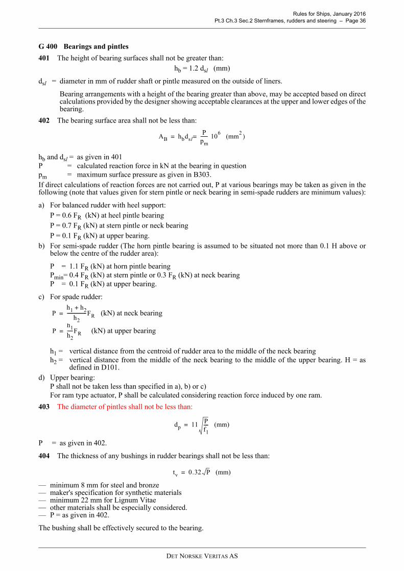
Rules for Ships, January 2016 Pt.3 Ch.3 Sec.2 Sternframes, rudders and steering – Page 36
G 400 Bearings and pintles
401 The height of bearing surfaces shall not be greater than:hb = 1.2 dsl (mm)
dsl = diameter in mm of rudder shaft or pintle measured on the outside of liners.
Bearing arrangements with a height of the bearing greater than above, may be accepted based on directcalculations provided by the designer showing acceptable clearances at the upper and lower edges of thebearing.
402 The bearing surface area shall not be less than:
hb and dsl = as given in 401P = calculated reaction force in kN at the bearing in questionpm = maximum surface pressure as given in B303.If direct calculations of reaction forces are not carried out, P at various bearings may be taken as given in thefollowing (note that values given for stern pintle or neck bearing in semi-spade rudders are minimum values):
a) For balanced rudder with heel support:P = 0.6 FR (kN) at heel pintle bearingP = 0.7 FR (kN) at stern pintle or neck bearingP = 0.1 FR (kN) at upper bearing.
b) For semi-spade rudder (The horn pintle bearing is assumed to be situated not more than 0.1 H above orbelow the centre of the rudder area):
P = 1.1 FR (kN) at horn pintle bearingPmin= 0.4 FR (kN) at stern pintle or 0.3 FR (kN) at neck bearingP = 0.1 FR (kN) at upper bearing.
c) For spade rudder:
(kN) at neck bearing
(kN) at upper bearing
h1 = vertical distance from the centroid of rudder area to the middle of the neck bearingh2 = vertical distance from the middle of the neck bearing to the middle of the upper bearing. H = as
defined in D101.d) Upper bearing:
P shall not be taken less than specified in a), b) or c)For ram type actuator, P shall be calculated considering reaction force induced by one ram.
403 The diameter of pintles shall not be less than:
P = as given in 402.
404 The thickness of any bushings in rudder bearings shall not be less than:
— minimum 8 mm for steel and bronze— maker's specification for synthetic materials— minimum 22 mm for Lignum Vitae— other materials shall be especially considered.— P = as given in 402.
The bushing shall be effectively secured to the bearing.
AB hbdslP
pm------= 10
6 (mm
2 )=
Ph1 h2+
h2-----------------FR=
Ph1
h2-----FR=
dp 11 Pf1---- (mm)=
tv 0.32 P (mm)=
DET NORSKE VERITAS AS

Rules for Ships, January 2016 Pt.3 Ch.3 Sec.2 Sternframes, rudders and steering – Page 37
Guidance note:Bushing fitted by means of shrink fitting alone is not considered effectively secured. Additional physical stoppersneed to be arranged to prevent the bushing from accidentally rotating or shifting in vertical direction.
---e-n-d---of---g-u-i-d-a-n-c-e---n-o-t-e---
The thickness of bearing material outside of the bushing shall not be less than:For balanced rudder or semi-spade rudders:
For spade rudders:
Reduced thickness may be accepted based on direct analysis.
P = as given in 402.
405 With metal bearings the clearance on the diameter is normally not to be less than:0.001 db + 1.0 (mm)
db = inner diameter in mm of the bushing.If non-metallic bearing material is applied, the bearing clearance shall be specially determined considering thematerials' swelling and thermal expansion properties. This clearance shall not be taken less than 1.5 mm on thebearing diameter unless a smaller clearance is supported by the manufacturer's recommendation and there isdocumented evidence of satisfactory service history with reduced clearance.The clearance should be related to the calculated angular deflection over the bearing length e.g. neck bearingof spade rudder.For pressure lubricated bearings the clearance will be especially considered.
406 Pintles shall have a conical attachment to the gudgeons. The conical pintle connection shall comply with the following:
An effective sealing against sea water shall be provided at both ends of the cone.Contact area shall be minimum 70% evenly distributed (see J200 for control and testing).The connection shall be secured by a nut which is properly locked to the pintle.The required push-up pressure for pintle bearings, in N/mm², is to be determined by the following formula:
where:
The push up length is to be calculated similarly as in 204, using required push-up pressure and properties forthe pintle bearing.
Dry fitting 1) Oil injection 2)
Length/diameter ratio (lt/dp) ≥1.0 ≥1.0Hub/pintle diameter ratio (D/dp)
≥1.5 ≥1.5
Taper of cone 1:8 to 1:12 1: ≥12Contact Surface roughness in micron (RA) maximum 3.5 Maximum 1.61) Slugging nut to be provided in accordance with 205. 2) The design shall enable escape of the oil from between the mating surfaces.
P = Supporting force in the pintle bearing, in kNd0 = Pintle diameter, in mm
t 1.7 Pf1---- (mm)=
t 2.0 Pf1---- (mm)=
2m
0req d
Pd400=p N/mm²
DET NORSKE VERITAS AS

Rules for Ships, January 2016 Pt.3 Ch.3 Sec.2 Sternframes, rudders and steering – Page 38
H. Propeller nozzles
H 100 General
101 The following requirements are applicable to fixed and steering nozzles.Guidance note:The scantlings and arrangement of large propeller nozzles should be specially considered with respect to excitingfrequencies from the propeller.
---e-n-d---of---g-u-i-d-a-n-c-e---n-o-t-e---
H 200 Plating
201 The thickness of the nozzle shell plating in the propeller zone shall not be less than:
where:
N = 0.01 PS D, need not be taken greater than 100PS = maximum continuous output (kW) delivered to the propellerD = inner diameter (m) of nozzles = distance in m between ring webs, shall not be taken less than 0.35 metres in the formulaka = aspect ratio correction as given in F201, to be applied when longitudinal stiffeners.
The thickness in zone I and II shall not be less than 0.7 t and in zone III not less than 0.6 t, corrected for spacings.The propeller zone shall be taken minimum 0.25 b (where b = length of nozzle). For steering nozzles thepropeller zone shall cover the variations in propeller position.On the outer side of the nozzle, zone II shall extend beyond the aftermost ring web.
202 The thickness of ring webs and fore and aft webs shall not be taken less than 0.6 t. They shall be increasedin thickness in way of nozzle supports.
203 If the ship is reinforced according to an ice class notation, the part of the outer shell of the nozzle which issituated within the ice belt shall have a plate thickness not less than corresponding to the ice class requirement forthe after part of the ship.
Guidance note:In order to prevent corrosion and erosion of the inner surface of the nozzle, application of a corrosion resistant materialin the propeller zone is recommended. All but welds should be ground smooth. When a corrosion resistant material is used, the plate thickness may be reduced by 15%.
---e-n-d---of---g-u-i-d-a-n-c-e---n-o-t-e---
H 300 Nozzle ring stiffness
301 In order to obtain a satisfactory stiffness of the nozzle ring the following requirement shall be fulfilled:I = 2.8 k b D3 V2 (cm4)
I = moment of inertia of nozzle section about the neutral axis parallel to centre line
k =
tm = mean thickness of nozzle inner and outer shell plating (mm), in propeller planeb = length of nozzle, see Fig.15, in mD = as given in 201V = maximum service speed (knots)n = number of ring webs.
t 10 3kasNf1---- (mm)+=
28b
Dtm n 1+( )--------------------------------
DET NORSKE VERITAS AS

Rules for Ships, January 2016 Pt.3 Ch.3 Sec.2 Sternframes, rudders and steering – Page 39
Fig. 15Section through nozzle ring
302 If the ship is reinforced according to an ice class notation the parameter V for the requirement in 301shall not be taken less than:
V = 14, 15, 16 and 17 knots for ice class 1C, 1B, 1A and 1A*, respectively.
H 400 Welding
401 The inner shell plate shall be welded to the ring webs with double continuous fillet welding.
402 The outer shell plate is as far as possible to be welded continuously to the ring webs. Slot welding maybe accepted on the following conditions:If the web spacing s ≤ 350 mm all welds to outer plating may be slot welds. If the web spacing s > 350 mm atleast two ring webs shall be welded continuously to the outer shell. A continuous weld according to Fig.17 maybe accepted.
H 500 Supports
501 The nozzle shall be supported by at least two supports. The web plates and shell plates of the supportstructure shall be in line with web plates in the nozzle.
I. Propeller shaft brackets
I 100 General
101 The following requirements are applicable to propeller shaft brackets having two struts to support thepropeller tail shaft boss. The struts may be of solid or welded type.
102 The angle between the struts shall not be less than 50 degrees.
I 200 Arrangement
201 Solid struts shall be carried continuously through the shell plating and shall be given satisfactory supportby the internal ship structure.
202 Welded struts may be welded to the shell plating. The shell plating shall be reinforced, and internalbrackets in line with strut plating shall be fitted. If the struts are built with a longitudinal centre plate, this plateshall be carried continuously through the shell plating. The struts shall be well rounded at fore and aft end atthe transition to the hull.
203 The propeller shaft boss shall have well rounded fore and aft brackets at the connection to the struts.
204 The strut structure inside the shell shall terminate within a compartment of limited volume to reduce theeffect of flooding in case of damage.
I 300 Struts
301 Solid or built-up struts of propeller shaft brackets shall comply with the following requirements:h = 0.4 d (mm)
A = 0.4 d2 (mm2)W = 0.12 d3 (mm3)
A = area of strut sectionW = section modulus of section. W shall be calculated with reference to the neutral axis Y-Y as indicated on
Fig.16
ZONE II Propeller zone ZONE I
ZONE III
b
min. b/4
DET NORSKE VERITAS AS

Rules for Ships, January 2016 Pt.3 Ch.3 Sec.2 Sternframes, rudders and steering – Page 40
h = the greatest thickness of the sectiond = Propeller shaft diameter in mm.
The diameter refers to shaft made of steel with a minimum specified tensile strength of 430 N/mm2.
Fig. 16Strut section
J. Welding, mounting and testing
J 100 Welding
101 Welds between plates and heavy pieces (cast or very thick plating) shall be made as full penetrationwelds. In way of highly stressed areas e.g. cut-out semi-spade rudder and upper part of spade rudder, cast orwelding on ribs shall be arranged.
102 Two sided full penetration welding shall normally be arranged. Where back welding is impossiblewelding shall be performed against ceramic backing bar or equivalent. Steel backing bars may be used and areto be continuously welded on one side to the heavy piece.
103 Webs shall be connected to the side plates in accordance with Ch.1 Sec.11. Weld factor C to be used is0.43
104 Slot-welding shall be limited as far as possible. Slot welding is not acceptable in areas with large in planestresses transversely to the slots or in way of cut-out areas of semi-spade rudders. Continuous slot welds as shown in figure 17 might be accepted in lieu of slot welds. When slot welding is applied, slots of minimum length 75 mm and a breadth of 2 t (where t = rudder platethickness), with a maximum distance of 125 mm between ends of slots, will be accepted. Slots shall not befilled with weld
J 200 Rudders and rudder stock connections
201 Contact area of conical connections shall be (minimum 70%) verified by means of paint test (e.g. tool-maker blue) in presence of the surveyor.
202 Test push-up followed by control of contact area may be required before final assembly for conicalkeyless connections intended for injection fitting, if calculations are considered inaccurate due to a non-symmetric design or other relevant reasons. Push-up length during test push-up shall not be less than final push-up length.
J 300 Testing of stern frames and rudders
301 Built stern frames and rudders with closed sections shall be leak tested on completion.Guidance note:Rudder and rudder horn is defined as critical area and at least 20% of the welded length is subject to non destructivetesting (see Pt.2. Ch.3 Sec.7).However, it is recommended that highly stressed welds between plates and heavy piecesare subject to 100 % examination with a corresponding reduction in the extent of less critical weld connections.
---e-n-d---of---g-u-i-d-a-n-c-e---n-o-t-e---
J 400 Mounting of rudder
401 For rudder with continuous shaft it shall be checked that the rudder shaft has the right position in relationto the upper coupling, both longitudinally and transversely, when the lower tapered part of the rudder axle bearshard at the heel. The rudder shaft shall be securely fastened at the heel before the coupling bolts at the upperend are fitted.
Y
Y
h
DET NORSKE VERITAS AS

Rules for Ships, January 2016 Pt.3 Ch.3 Sec.2 Sternframes, rudders and steering – Page 41
402 Before final mounting of rudder pintles, the contact between conical surfaces of pintles and theirhousings shall be checked by marking with Prussian blue or by similar method. When mounting the pintles,care shall be taken to ensure that packings will not obstruct the contact between mating surfaces. The pintle andits nut shall be so secured that they cannot move relatively to each other.
Fig. 17Connection shell plate/ring web
6 – 10 mm15°
DET NORSKE VERITAS AS

Rules for Ships, January 2016 Pt.3 Ch.3 Sec.3 Anchoring and mooring equipment – Page 42
SECTION 3 ANCHORING AND MOORING EQUIPMENT
A. General
A 100 Introduction
101 The requirements in this section apply to equipment and installation for anchoring and mooring.
102 Towlines and mooring lines are not subject to classification. Lengths and breaking strength are, however,given in the equipment tables as guidance. If voluntary certification of such equipment is requested, it shall becarried out in accordance with G.
A 200 Documentation requirement
201 Documentation shall be submitted as required by Table A1.
202 For general requirements to documentation, including definition of the Info codes, see Pt.0 Ch.3 Sec.1.
203 For a full definition of the documentation types, see Pt.0 Ch.3 Sec.2.
A 300 Certification
301 Components shall be certified as required by Table A2.
Table A1 Documentation requirementsObject Documentation type Additional description Info
Anchoring and mooring arrangement
Z030 – Arrangement plan Including design loads. FI
Z090 – Equipment listCovering windlasses, anchors, grade of anchor chain, type and breaking load of chain, wire and fibre ropes.
AP
H100 – Equipment number calculation AP
Anchors
C010 – Design criteriaApplicable if different from standard or previously approved design.
FI
C030 – Detailed drawing AP
C040 – Design analysis FI
Anchor chain stoppers
C010 – Design criteria FI
C020 – Assembly or arrangement drawing FI
C030 – Detailed drawing AP
C040 – Design analysis FI
Anchor windlasses
C010 – Design criteria FI
C020 – Assembly or arrangement drawing FI
C040 – Design analysis FI
C050 – Non-destructive testing (NDT) plan AP
C030 – Detailed drawing Cable lifter, drum, shaft, gear, brake, clutch and frame. AP
Table A2 - Certification requirementsObject Certificate type Additional description
AnchorsNV-P DNV product certificateNV-M DNV material certificate
Anchor lines
NV-P DNV product certificateChains, including accessories, e.g. swivels.
NV-M DNV material certificate
W-M Works material certificateSteel wire ropes.Fibre ropes.
Anchor chain joining shacklesNV-P DNV product certificateNV-M DNV material certificate
DET NORSKE VERITAS AS

Rules for Ships, January 2016 Pt.3 Ch.3 Sec.3 Anchoring and mooring equipment – Page 43
302 For a definition of the certificate types, see Pt.1 Ch.1 Sec.4 B.
A 400 Assumptions
401 The anchoring equipment required is the minimum considered necessary for temporary mooring of avessel in moderate sea conditions when the vessel is awaiting berth, tide, etc. The equipment is therefore notdesigned to hold a vessel off fully exposed coasts in rough weather or for frequent anchoring operations in opensea. In such conditions the loads on the anchoring equipment will increase to such a degree that its componentsmay be damaged or lost owing to the high energy forces generated.
Guidance note:If the intended service of the vessel is such that frequent anchoring in open sea is expected, it is advised that the sizeof anchors and chains is increased above the rule requirements, taking into account the dynamic forces imposed bythe vessel moving in heavy seas. The Equipment Numeral (EN) formula for required anchoring equipment is basedon an assumed current speed of 2.5 m/s, wind speed of 25 m/s and a scope of chain cable between 6 and 10, the scopebeing the ratio between length of chain paid out and water depth.
---e-n-d---of---g-u-i-d-a-n-c-e---n-o-t-e---
402 The anchoring equipment required by the Rules is designed to hold a vessel in good holding ground inconditions such as to avoid dragging of the anchor. In poor holding ground the holding power of the anchorswill be significantly reduced.
403 It is assumed that under normal circumstances the vessel will use only one bower anchor and chain cableat a time.
B. Structural arrangement for anchoring equipment
B 100 General
101 The anchors are normally to be housed in hawse pipes of suitable size and form to prevent movement ofanchor and chain due to wave action.The arrangements shall provide an easy lead of the chain cable from the windlass to the anchors. Upon releaseof the brake, the anchor is immediately to start falling by its own weight. At the upper and lower ends of hawsepipes, there shall be chafing lips. There shall be well rounded parts at the upper and lower ends of the hawsepipes, anchor pocket or bell mouth in those areas where the chain cable is supported during paying out andhoisting and when the vessel is laying at anchor. Alternatively, roller fairleads of suitable design may be fitted.Where hawse pipes are not fitted alternative arrangements will be specially considered.
102 The shell plating in way of the hawse pipes shall be increased in thickness and the framing reinforced asnecessary to ensure a rigid fastening of the hawse pipes to the hull.
Guidance note:The diameter ratio, D/d, between the curvature of the rounded parts at lower end of anchor pocket, hawse pipe or bellmouth and the anchor chain cable shall be minimum 6.
---e-n-d---of---g-u-i-d-a-n-c-e---n-o-t-e---
103 Ships provided with a bulbous bow, and where it is not possible to obtain ample clearance between shellplating and anchors during anchor handling, local reinforcements of bulbous bow shall be provided asnecessary.
104 The chain locker shall have adequate capacity and a suitable form to provide a proper stowage of thechain cable, and an easy direct lead for the cable into the spurling pipes, when the cable is fully stowed. Portand starboard cables shall have separate spaces. If 3 bower anchors and 3 hawse pipes are used, there shall be3 separate spaces. Spurling pipes and chain lockers shall be watertight up to the weather deck.
Anchor windlasses
NV-P DNV product certificate
NV-M DNV material certificate
Cable lifter.Drum.Shaft.Clutch.Brake.Gear.
W-M Works material certificate Frame.Chain stoppers NV-M DNV material certificate
Table A2 - Certification requirements (Continued)Object Certificate type Additional description
DET NORSKE VERITAS AS

Rules for Ships, January 2016 Pt.3 Ch.3 Sec.3 Anchoring and mooring equipment – Page 44
Guidance note:Bulkheads separating adjacent chain lockers need not be watertight.
---e-n-d---of---g-u-i-d-a-n-c-e---n-o-t-e---
Where means of access are provided, they shall be closed by a substantial cover and secured by closely spacedbolts. Where a means of access to spurling pipes or cable lockers is located below the weather deck, the access coverand its securing arrangements are to be in accordance with recognized standards (see Guidance note 3) orequivalent for watertight manhole covers. Butterfly nuts and/or hinged bolts are prohibited as the securingmechanism for the access cover.Spurling pipes through which anchor cables are led shall be provided with permanently attached closingappliances to minimize water ingress. Adequate drainage facilities of the chain locker shall be adopted.Provisions shall be made for securing the inboard ends of chain to the structure. This attachment shall be ableto withstand a force of not less than 15% nor more than 30% of the minimum breaking strength of the chaincable. The fastening of the chain to the ship shall be made in such a way that in case of emergency when anchorand chain have to be sacrificed, the chain can be readily made to slip from an accessible position outside thechain locker.
Guidance note 1:The spurling pipe is the pipe between the chain locker and the weather deck.
---e-n-d---of---g-u-i-d-a-n-c-e---n-o-t-e---
Guidance note 2:The emergency release of the chain dead end should consequently be arranged watertight or above the weather deck.
---e-n-d---of---g-u-i-d-a-n-c-e---n-o-t-e---
Guidance note 3:Concerning permanently attached appliances.Examples of the recognized standards are such as:
i) ISO 5894-1999
ii) China: GB 11628-1989 Ship Manhole Cover
iii) India: IS 15876-2009 “Ships and Marine Technology manholes with bolted covers”
iv) Japan: JIS F2304, “Ship's Manholes” and JIS F2329, “Marine Small Size Manhole”
v) Korea: KSV 2339:2006 and KS VISO5894
vi) Norway: NS 6260:1985 to NS 6266:1985
vii) Russia: GOST 2021-90 “Ship's steel manholes. Specifications”.
---e-n-d---of---g-u-i-d-a-n-c-e---n-o-t-e---
(IACS UR L4 Rev. 3)
105 The windlass and chain stoppers shall be efficiently bedded to the deck. The deck plating in way ofwindlass and chainstopper shall be increased in thickness and supported by pillars carried down to rigidstructures. See Sec.5 B.
C. Equipment specification
C 100 Equipment number
101 The equipment number is given by the formula:E N = Δ2/3 + 2 B H + 0.1 A
H = effective height in m from the summer load waterline to the top of the uppermost deckhouse, to bemeasured as follows:
H = a + Σ hi
a = distance in m from summer load waterline amidships to the upper deck at sidehi = height in m on the centre line of each tier of houses having a breadth greater than B/4. For the lowest
tier, hi shall be measured at centre line from the upper deck, or from a notional deck line where there islocal discontinuity in the upper deck
A = area in m2 in profile view of the hull, superstructures and houses above the summer load waterline,which is within L of the ship. Houses of breadth less than B/4 shall be disregarded.
DET NORSKE VERITAS AS

Rules for Ships, January 2016 Pt.3 Ch.3 Sec.3 Anchoring and mooring equipment – Page 45
In the calculation of Σ hi and A sheer and trim shall be ignored.Windscreens or bulwarks more than 1.5 m in height shall be regarded as parts of superstructures and of houseswhen determining H and A. The total area of the mentioned items measured from the deck, shall be included.
Guidance note:According to IACS UR A1, the height of the hatch coamings and that of any deck cargo, such as containers, may bedisregarded when determining h and A.
---e-n-d---of---g-u-i-d-a-n-c-e---n-o-t-e---
102 For a barge rigidly connected to a push-tug the equipment number shall be calculated for the combinationregarded as one unit.
DET NORSKE VERITAS AS

Rules for Ships, January 2016 Pt.3 Ch.3 Sec.3 Anchoring and mooring equipment – Page 46
Table C1 Equipment, general
Equipment number
Equipment letter
Stockless bower anchors Stud-link chain cables Towline
(guidance)Mooring lines 1)
(guidance)
Number
Mass per
anchor
kg
Total length
Diameter and steel grade Steel or fibre ropes Steel or fibre ropes
m
NV K1
mm
NV K2
mm
NV K3
mm
Minimum length
m
Minimum breaking strength
kN
Number
Length of each
m
Minimum breaking strength
kN30 to 4950 to 6970 to 8990 to 109
a0abc
2222
120180240300
192.5220220
247.5
12.51416
17.5
12.51416
170180180180
88.598.098.098.0
2333
8080100110
32343739
110 to 129130 to 149150 to 174
def
222
360420480
247.5275275
1920.522
17.517.519
180180180
989898
333
110120120
444954
175 to 204205 to 239240 to 279
ghi
222
570660780
302.5302.5330
242628
20.52224
20.522
180180180
112129150
344
120120120
596469
280 to 319320 to 359360 to 399
jkl
222
90010201140
357.5357.5385
303234
262830
242426
180180180
174207224
444
140140140
747888
400 to 449450 to 499500 to 549
mno
222
129014401590
385412.5412.5
363840
323434
283030
180180190
250277306
444
140140160
98108123
550 to 599600 to 659660 to 719
pqr
222
174019202100
440440440
424446
363840
323436
190190190
338371406
444
160160160
132147157
720 to 779780 to 839840 to 909
stu
222
228024602640
467.5467.5467.5
485052
424446
363840
190190190
441480518
444
170170170
172186201
910 to 979980 to 10591060 to 1139
vwx
222
285030603300
495495495
545658
485050
424446
190200200
559603647
444
170180180
216230250
1140 to 12191220 to 12991300 to 1389
yzA
222
354037804050
522.5522.5522.5
606264
525456
464850
200200200
691738786
444
180180180
270284309
1390 to 14791480 to 15691570 to 1669
BCD
222
432045904890
550550550
666870
586062
505254
200220220
836888941
455
180190190
324324333
1670 to 17891790 to 19291930 to 2079
EFG
222
525056106000
577.5577.5577.5
737678
646668
565860
220220220
102411091168
555
190190190
353378402
2080 to 22292230 to 23792380 to 2529
HIJ
222
645069007350
605605605
818487
707376
626466
240240240
125913561453
555
200200200
422451480
2530 to 26992700 to 28692870 to 3039
KLM
222
780083008700
632.5632.5632.5
909295
788184
687073
260260260
147114711471
666
200200200
480490500
3040 to 32093210 to 33993400 to 3599
NOP
222
9300990010500
660660660
97100102
848790
767878
280280280
147114711471
666
200200200
520554588
3600 to 37993800 to 39994000 to 4199
QRS
222
111001170012300
687.5687.5687.5
105107111
929597
818487
300300300
147114711471
667
200200200
618647647
4200 to 43994400 to 45994600 to 4799
TUV
222
129001350014100
715715715
114117120
100102105
879092
300300300
147114711471
777
200200200
657667677
4800 to 49995000 to 51995200 to 5499
WXY
222
147001540016100
742.5742.5742.5
122124127
107111111
959797
300300300
147114711471
788
200200200
686686696
5500 to 57995800 to 60996100 to 6499
ZA*B*
222
169001780018800
742.5742.5742.5
130132137
114117120
100102107
300300300
147114711471
889
200200200
706706716
6500 to 68996900 to 73997400 to 7899
C*D*E*
222
200002150023000
770770770
124127132
111114117
300300300
147114711471
91011
200200200
726726726
DET NORSKE VERITAS AS

Rules for Ships, January 2016 Pt.3 Ch.3 Sec.3 Anchoring and mooring equipment – Page 47
C 200 Equipment tables
201 The equipment is in general to be in accordance with the requirements given in Table C1.The two bower anchors and their cables shall be connected and stowed in position ready for use. The totallength of chain cable required shall be equally divided between the two anchors. The towline and the mooringlines are given as guidance only, representing a minimum standard, and shall not be considered as conditionsof class.
Guidance note:If anchor chain total length is an uneven number of shackles, no more than one standard shackle (27.5 m) differencein length is allowed between the two anchors.
---e-n-d---of---g-u-i-d-a-n-c-e---n-o-t-e---
202 For fishing vessels the equipment shall be in accordance with the requirements given in Table C2. Whenthe equipment number is larger than 720, table C1 should be applied.
203 Unmanned barges are only to have equipment consisting of 2 mooring lines with length as required byTable C1.
204 For ships and manned barges with restricted service the equipment specified in Table C1 and C2 may bereduced in accordance with Table C3. No reductions are given for class notations R0 and R1.
205 For ships and manned barges with equipment number EN less than 205 and fishing vessels with EN lessthan 500 the anchor and chain equipment specified in Table C1 and C2 may be reduced, on application fromthe Owners, based upon a special consideration of the intended service area of the vessel. The reduction shallnot be more than given for the service notation R4 in Table C3. In such cases a minus sign will be given inbrackets after the equipment letter for the vessel in the “Register of vessels classed with DNV”, e.g. f(–).
7900 to 83998400 to 88998900 to 93999400 to 9999
F*G*H*I*
2222
24500260002750029000
770770770770
137142147152
122127132132
300300300300
1471147114711471
11121314
200200200200
735735735735
10000 to 10699
10700 to 11499
11500 to 12399
J*K*L*
222
310003300035500
770770770
137142147
151617
200200200
735735735
12400 to 13399
13400 to 14599
14600 to 16000
M*N*O*
222
385004200046000
770770770
152157162
181921
200200200
735735735
1) For individual mooring lines with breaking force above 490 kN according to the table, the strength may be reduced by the corresponding increase of the number of mooring lines and vice versa. The total breaking force of all mooring lines on board should not be less than according to the table. However, the number of mooring should not be less than 6, and no line should have a breaking force less than 490 kN.
Table C1 Equipment, general (Continued)
Equipment number
Equipment letter
Stockless bower anchors Stud-link chain cables Towline
(guidance)Mooring lines 1)
(guidance)
Number
Mass per
anchor
kg
Total length
Diameter and steel grade Steel or fibre ropes Steel or fibre ropes
m
NV K1
mm
NV K2
mm
NV K3
mm
Minimum length
m
Minimum breaking strength
kN
Number
Length of each
m
Minimum breaking strength
kN
DET NORSKE VERITAS AS

Rules for Ships, January 2016 Pt.3 Ch.3 Sec.3 Anchoring and mooring equipment – Page 48
D. Anchors
D 100 General
101 Anchor types dealt with are:
— ordinary stockless bower anchor— ordinary stocked bower anchor— H.H.P. (“High Holding Power”) anchor— S.H.H.P. ("Super High Holding Power") anchor.
102 The mass of ordinary stockless bower anchors shall not be less than given in C. The mass of individualanchors may vary by 7% of the table value, provided that the total mass of anchors is not less than would havebeen required for anchors of equal mass.The mass of the head shall not be less than 60% of the table value.
103 The mass of stocked bower anchor, the stock not included, shall not be less than 80% of the table-value
Table C2 Equipment for fishing vessels and sealers
Equipment number
Equipment letter
Stockless bower anchors Stud-link chain cables Towline
(guidance)Mooring lines
(guidance)
Number
Mass per
anchor
kg
Total length
Diameter and steel grade Steel or fibre ropes Steel or fibre ropes
m
NV K1
mm
NV K2
mm
Minimum length
m
Minimum breaking strength
kN
Number
Length of
each
m
Minimum breaking strength
kN
30 to 3940 to 4950 to 5960 to 69
a0f1a0f2af1af2
2222
80100120140
165192.5192.5192.
1111
12.512.5
180180
9898
2233
50608080
29293434
70 to 7980 to 8990 to 99
100 to 109
bf1bf2cf1cf2
2222
160180210240
220220220220
14141616
12.512.51414
180180180180
98989898
3333
100100110110
37373939
110 to 119120 to 129130 to 139140 to 149
df1df2ef1ef2
2222
270300340390
247.5247.5275275
17.517.51919
1616
17.517.5
180180180180
98989898
3333
110110120120
44444949
150 to 174175 to 204205 to 239240 to 279
fghi
2222
480570660780
275302.5302.5330
22242628
1920.52224
180180180180
98112129150
3344
120120120120
54596469
280 to 319320 to 359360 to 399
jkl
222
90010201140
357.5357.5385
303234
262830
180180180
174207224
444
140140140
747888
400 to 449450 to 499500 to 549
mno
222
129014401590
385412.5412.5
363840
323434
180180190
250277306
444
140140160
98108123
550 to 599600 to 659660 to 720
pqr
222
174019202100
440440440
424446
363840
190190190
338371406
444
160160160
132147157
Table C3 Equipment reductions for service restriction notations. (See Table C1)Class
notationStockless bower
anchorsStud-link
chain cablesNumber Mass change
per anchorLength
reductionDiameter
R2 R3 R4 RE
2222
- 10%- 20%- 30%- 40%
No red.No red.- 20%- 30%
No red.No red.- 10%- 20%
Alternatively:R3 R4 RE
111
+40%No change
- 20%
- 40%- 50%- 60%
No red.No red.- 10%
DET NORSKE VERITAS AS
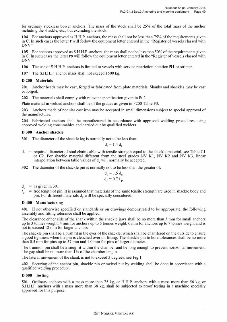
Rules for Ships, January 2016 Pt.3 Ch.3 Sec.3 Anchoring and mooring equipment – Page 49
for ordinary stockless bower anchors. The mass of the stock shall be 25% of the total mass of the anchorincluding the shackle, etc., but excluding the stock.
104 For anchors approved as H.H.P. anchors, the mass shall not be less than 75% of the requirements givenin C. In such cases the letter r will follow the equipment letter entered in the “Register of vessels classed withDNV”.
105 For anchors approved as S.H.H.P. anchors, the mass shall not be less than 50% of the requirements givenin C. In such cases the letter rs will follow the equipment letter entered in the “Register of vessels classed withDNV”.
106 The use of S.H.H.P. anchors is limited to vessels with service restriction notation R1 or stricter.
107 The S.H.H.P. anchor mass shall not exceed 1500 kg.
D 200 Materials
201 Anchor heads may be cast, forged or fabricated from plate materials. Shanks and shackles may be castor forged.
202 The materials shall comply with relevant specification given in Pt.2.Plate material in welded anchors shall be of the grades as given in F200 Table F3.
203 Anchors made of nodular cast iron may be accepted in small dimensions subject to special approval ofthe manufacturer.
204 Fabricated anchors shall be manufactured in accordance with approved welding procedures usingapproved welding consumables and carried out by qualified welders.
D 300 Anchor shackle
301 The diameter of the shackle leg is normally not to be less than:ds = 1.4 dc
dc = required diameter of stud chain cable with tensile strength equal to the shackle material, see Table C1or C2. For shackle material different from the steel grades NV K1, NV K2 and NV K3, linearinterpolation between table values of dc will normally be accepted.
302 The diameter of the shackle pin is normally not to be less than the greater of:dp = 1.5 dc
dp = 0.7 l p
dc = as given in 301lp = free length of pin. It is assumed that materials of the same tensile strength are used in shackle body and
pin. For different materials dp will be specially considered.
D 400 Manufacturing
401 If not otherwise specified on standards or on drawings demonstrated to be appropriate, the followingassembly and fitting tolerance shall be applied.The clearance either side of the shank within the shackle jaws shall be no more than 3 mm for small anchorsup to 3 tonnes weight, 4 mm for anchors up to 5 tonnes weight, 6 mm for anchors up to 7 tonnes weight and isnot to exceed 12 mm for larger anchors.The shackle pin shall be a push fit in the eyes of the shackle, which shall be chamfered on the outside to ensurea good tightness when the pin is clenched over on fitting. The shackle pin to hole tolerances shall be no morethan 0.5 mm for pins up to 57 mm and 1.0 mm for pins of larger diameter.The trunnion pin shall be a snug fit within the chamber and be long enough to prevent horizontal movement.The gap shall be no more than 1% of the chamber length.The lateral movement of the shank is not to exceed 3 degrees, see Fig.1.
402 Securing of the anchor pin, shackle pin or swivel nut by welding shall be done in accordance with aqualified welding procedure.
D 500 Testing
501 Ordinary anchors with a mass more than 75 kg, or H.H.P. anchors with a mass more than 56 kg, orS.H.H.P. anchors with a mass more than 38 kg, shall be subjected to proof testing in a machine speciallyapproved for this purpose.
DET NORSKE VERITAS AS
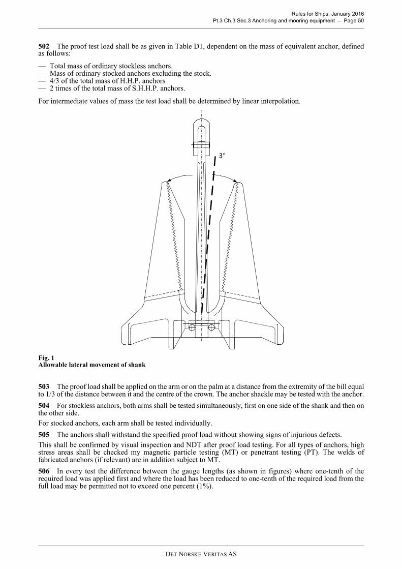
Rules for Ships, January 2016 Pt.3 Ch.3 Sec.3 Anchoring and mooring equipment – Page 50
502 The proof test load shall be as given in Table D1, dependent on the mass of equivalent anchor, definedas follows:
— Total mass of ordinary stockless anchors.— Mass of ordinary stocked anchors excluding the stock.— 4/3 of the total mass of H.H.P. anchors— 2 times of the total mass of S.H.H.P. anchors.
For intermediate values of mass the test load shall be determined by linear interpolation.
Fig. 1Allowable lateral movement of shank
503 The proof load shall be applied on the arm or on the palm at a distance from the extremity of the bill equalto 1/3 of the distance between it and the centre of the crown. The anchor shackle may be tested with the anchor.
504 For stockless anchors, both arms shall be tested simultaneously, first on one side of the shank and then onthe other side.For stocked anchors, each arm shall be tested individually.
505 The anchors shall withstand the specified proof load without showing signs of injurious defects.This shall be confirmed by visual inspection and NDT after proof load testing. For all types of anchors, highstress areas shall be checked my magnetic particle testing (MT) or penetrant testing (PT). The welds offabricated anchors (if relevant) are in addition subject to MT.
506 In every test the difference between the gauge lengths (as shown in figures) where one-tenth of therequired load was applied first and where the load has been reduced to one-tenth of the required load from thefull load may be permitted not to exceed one percent (1%).
3°
DET NORSKE VERITAS AS

Rules for Ships, January 2016 Pt.3 Ch.3 Sec.3 Anchoring and mooring equipment – Page 51
Fig. 2Gauge length
D 600 Additional requirements for H.H.P. and S.H.H.P. anchors
601 H.H.P. and S.H.H.P. anchors shall be designed for effective hold of the sea bed irrespective of the angleor position at which they first settle on the sea bed after dropping from a normal type of hawse pipe. In case ofdoubt a demonstration of these abilities may be required.
602 The design approval of H.H.P. and S.H.H.P. anchors are normally given as a type approval, and theanchors are listed in the Register of Type Approved Products No.3 "Structural Equipment, Containers, CargoHandling and Securing Equipment".The design approval of H.H.P. anchors is normally given as a type approval, and the anchors are listed in the"Register of Type Approved Products No.3: Containers, Cargo Handling, Lifting Appliances andMiscellaneous Equipment."
603 H.H.P. anchors for which approval is sought shall be tested on sea bed to show that they have a holdingpower per unit of mass at least twice that of an ordinary stockless bower anchor. The mean value of three tests(for each anchor and nature of sea bed, ref. 608) shall form the basis for holding power.
604 S.H.H.P. anchors for which approval is sought shall be tested on sea bed to show that they have a holdingpower per unit of mass at least 4 times that of an ordinary stockless bower anchor. The mean value of three tests (foreach anchor and nature of sea bed, ref. 608) shall form the basis for holding power.
605 If approval is sought for a range of H.H.P. anchor sizes, at least two sizes shall be tested. The mass ofthe larger anchor to be tested shall not be less than 1/10 of that of the largest anchor for which approval issought. The smaller of the two anchors to be tested shall have a mass not less than 1/10 of that of the larger.
606 If approval is sought for a range of S.H.H.P. anchor sizes, at least three sizes shall be tested, indicativeof the bottom, middle and top of the mass range.
607 Each test shall comprise a comparison between at least two anchors, one ordinary stockless bower anchorand one H.H.P. or S.H.H.P. anchor. The mass of the anchors shall be as equal as possible.
608 The tests shall be conducted on at least 3 different types of bottom, which normally shall be: soft mud orsilt, sand or gravel, and hard clay or similar compacted material.
609 The tests are normally to be carried out by means of a tug. The pull shall be measured by dynamometeror determined from recently verified curves of the tug's bollard pull as function of propeller r.p.m.The diameter of the chain cables connected to the anchors shall be as required for the equipment letter inquestion. During the test the length of the chain cable on each anchor shall be sufficient to obtain anapproximately horizontal pull on the anchor. Normally, a horizontal distance between anchor and tug equal to10 times the water depth will be sufficient.
D 700 Identification
701 The following marks shall be stamped on one side of the anchor:
— Mass of anchor (excluding possible stock)— H.H.P., when approved as high holding power anchor— S.H.H.P., when approved as super high holding power anchor— Certificate No.— Date of test— Det Norske Veritas' stamp— Manufacturer's mark— Additionally the unique cast identification shall be cast on the shank and the fluke.
DET NORSKE VERITAS AS

Rules for Ships, January 2016 Pt.3 Ch.3 Sec.3 Anchoring and mooring equipment – Page 52
E. Anchor chain cables
E 100 General requirements
101 Chain cables and accessories shall be designed according to a recognized standard, such as ISO 1704. Alength of chain cable shall measure not more than 27.5 m and shall comprise an odd number of links. Wheredesigns do not comply with this, drawings giving details of the design shall be submitted for approval.
102 The form and proportion of links and accessories together with examples of connections of links,shackles and swivels are shown in Fig.3. Other design solutions, e.g. short link chain cable or steel wire ropemay be accepted after special consideration.
103 The diameter of stud link chain cable shall not be less than given in C.If ordinary short link chain cable is accepted instead of stud link chain cable at least the same proof load willnormally be required. For fishing vessels with equipment number EN ≤ 110, the diameter shall be at least 20%in excess of the table value for the chain grade used.
104 Chain grade NV K1 shall normally not be used in association with H.H.P. or S.H.H.P. anchors.
105 Chain grade NV K3 shall not be used for chain diameter less than 20.5 mm.
106 Ships equipped with chain cable grade NV K2 or NV K3 will have the letters s or sh, respectively, addedto the equipment letter.
107 Steel wire rope instead of stud link chain cable may be accepted for vessels of special design or operation,for vessels with restricted services and for fishing vessels. The acceptance will be based on a case-by-caseevaluation, including consideration of operational and safety aspects. If steel wire rope is accepted, thefollowing shall be fulfilled:
— the steel wire rope shall have at least the same breaking strength as the stud link chain cable— a length of chain cable shall be fitted between the anchor and the steel wire rope. The length shall be taken
as the smaller of 12.5 m and the distance between the anchor in stowed position and the winch— the anchor weight shall be increased by 25%— the length of the steel wire rope shall be at least 50% above the table value for the chain cable— a corresponding “Memo to Owner” (MO) shall be issued.
Arrangements applying the steel wire ropes of trawl winches may be accepted, provided the strength of the ropeis sufficient.
Table D1 Proof test load for anchorsMass of anchor
kg
Proof test
load kN
Mass of anchor
kg
Proof test
load kN
Mass of anchor
kg
Proof test
load kN
Mass of anchor
kg
Proof test
load kN
Mass of anchor
kg
Proof test
load kN
Mass of anchor
kg
Proof test
load kN5055606570758090100120140160180200225250275300325350375400425450475500
23.225.227.128.930.732.433.936.339.144.349.153.357.461.366.870.474.979.684.288.893.497.9103107112116
55060065070075080085090095010001050110011501200125013001350140014501500160017001800190020002100
125132140149158166175182191199208216224231239247255262270278292307321335349362
22002300240025002600270028002900300031003200330034003500360037003800390040004100420043004400450046004700
376388401414427438450462474484495506517528537547557567577586595604613622631638
48004900500051005200530054005500560057005800590060006100620063006400650066006700680069007000720074007600
645653661669677685691699706713721728735740747754760767773779786795804818832845
78008000820084008600880090009200940096009800100001050011000115001200012500130001350014000145001500015500160001650017000
861877892908922936949961975987999101010401070109011101130116011801210123012601270130013301360
1750018000185001900019500200002100022000230002400025000260002700028000290003000031000320003400036000380004000042000440004600048000
13901410144014701490152015701620167017201770180018501900194019902030207021602250233024102490257026502730
DET NORSKE VERITAS AS

Rules for Ships, January 2016 Pt.3 Ch.3 Sec.3 Anchoring and mooring equipment – Page 53
Fig. 3Standard dimensions of stud link chain cable and examples of connectionsD = dc = rule diameter of chain cables
DET NORSKE VERITAS AS

Rules for Ships, January 2016 Pt.3 Ch.3 Sec.3 Anchoring and mooring equipment – Page 54
E 200 Materials and manufacture
201 Chain cables shall be made by manufacturers approved by the Society for the pertinent grade of chaincable, size and method of manufacture. Steel forgings and castings for accessories shall be made bymanufacturers approved by the Society for the pertinent type of steel.
202 Stud link chain cables shall be manufactured by flash butt welding or, in the case of grade NV K2 and 3chain cables, drop forging or casting. Pressure butt welding may also be approved for grade NV K1 and 2 shortlink chain cables provided that the nominal diameter of the chain cable does not exceed 26 mm.
203 Bar material for chain cables shall be in accordance with Pt.2 Ch.2 Sec.6. Studs for chain cable links shallbe made of forged or cast steel. The carbon content in stud materials should not exceed 0.25% if studs shall bewelded into the links.
204 Where studs are welded into the links this shall be completed before the chain cable is heat treated. Studwelds shall be made by qualified welders or operators using an approved procedure and low hydrogenconsumables or processes. The stud ends shall be a good fit inside the link and the weld shall be confined tothe stud end opposite the flash butt weld. The full periphery of the stud end shall be welded unless otherwiseapproved.
205 Accessories such as shackles and swivels shall be made of forged or cast steel in accordance with thegeneral requirements in Pt.2 Ch.2 Sec.5 or Sec.7, as appropriate. Tapered locking pins for detachablecomponents shall be made of stainless or tinned steel with a lead stopper at the thick end.
E 300 Heat treatment
301 Chain cables and accessories shall be supplied in one of the conditions given in Table E1. Wherealternative conditions are permitted, the manufacturer shall supply chain cables and accessories only in thoseconditions for which he has been approved.
302 When heat treating in batch furnaces, links shall be stretched out or otherwise suitably arranged to ensureuniform heating and cooling.
E 400 Proof load testing
401 Each length of chain cable and all accessories shall be proof load tested in the condition of supply andshall withstand the proof load specified in Table E2 or Table E3 without fracture. Accessories shall besubjected to the proof load prescribed for the chain cable grade and size for which they are intended.
402 If one link fails during testing, the defective link shall be removed and replaced by a connecting link ofan approved type and the proof test again applied. In addition it shall be determined by examination that theprobable cause of failure is not present in any of the remaining links. If a second link fails, the length shall berejected.
403 If an accessory fails, it shall be rejected. In addition it shall be determined by examination that theprobable cause of failure is not present in any of the remaining items.
E 500 Breaking load testing
501 Samples of chain cables and accessories shall be breaking load tested in the condition of supply and shallwithstand the breaking load specified in Tables E2 or E3. Accessories shall be subjected to the breaking loadprescribed for the chain cable grade and size for which they are intended. End links and enlarged links need notbe tested provided that they are manufactured and heat treated with the chain cable. It will be consideredacceptable if the samples show no sign of fracture after application of the minimum specified load for 30seconds.
502 For chain cables, one sample consisting of at least three links shall be taken at the frequency given in503. Sample links for testing shall be made as part of the chain cable. They may be removed prior to heattreatment provided that:
Table E1 Condition of supply for chain cables and accessoriesGrade Chain cables AccessoriesNV K1 As welded or Normalised NANV K2 As welded or Normalised1) Normalised
NV K3Normalised,
Normalised and Tempered,Quenched and Tempered
Normalised, Normalised and Tempered,Quenched and Tempered
NA = Not Applicable
1) NV K2 chain cables made by forging or casting shall be supplied in the normalised condition.
— each sample is properly identified with the chain represented, and
DET NORSKE VERITAS AS
Rules for Ships, January 2016 Pt.3 Ch.3 Sec.3 Anchoring and mooring equipment – Page 55
503 For flash butt welded or drop forged chain cables, one sample shall be taken from every four lengths of27.5 m or less. For cast link chain cables, one sample shall be taken from each heat treatment charge with aminimum of one from every four lengths of 27.5 m or less.
504 For accessories, one sample item out of every test unit (batch) shall be taken. A test unit shall consist ofup to 25 items, or up to 50 in the case of Kenter shackles, of the same accessory type, grade, size and heattreatment procedure. The test unit need not necessarily be representative of each heat of steel, heat treatmentcharge or individual purchase order.
505 Except as provided in 506, accessories that have been breaking load tested shall be discarded and notused as part of an outfit.
506 Accessories that have been breaking load tested may be used as part of an outfit provided that:
507 The Society may waive the breaking load test of accessories provided that:
508 For the purpose of waiving the breaking load test of accessories, a manufacturing batch (test unit) shallconsist of up to 25 items, or up to 50 in the case of Kenter shackles, of the same type, grade, size and heattreatment charge. The test unit need not necessarily be representative of each heat of steel or individualpurchase order.
509 If a chain cable sample fails, a further sample shall be cut from the same length of cable and subjected tothe test. If this re-test fails, the length of cable shall be rejected. When this test is also representative of otherlengths, each of the remaining lengths shall be individually tested. If one of these further tests fails, all lengthsrepresented by the original test shall be rejected.
510 If an accessory fails, two more accessories from the same test unit shall be selected and subjected to thetest. If either of these further tests fails, the test unit shall be rejected.
— each sample is securely attached to and heat treated with the chain represented.
— the accessory is of higher grade than the chain cable for which it is intended, e.g. grade 3 accessory of grade 2 size in grade 2 chain, or
— the accessory is specially approved and designed with increased dimensions so that the breaking strength is not less than 1.4 times the break load of the chain cable for which it is intended.
— the breaking load test has been completed satisfactorily during approval testing of the same type of accessory, and— the tensile and impact properties of each manufacturing batch, see 510, are proved, and— the accessories are subjected to suitable non-destructive testing.
DET NORSKE VERITAS AS

Rules for Ships, January 2016 Pt.3 Ch.3 Sec.3 Anchoring and mooring equipment – Page 56
Table E2 Proof and breaking loads for stud link chain cables and accessories
Diameter of chain
mm
Grade NV K1 Grade NV K2 Grade NV K3 Guidance
Proof load kN
Breaking load kN
Proof load kN
Breaking load kN
Proof load kN
Breaking load kN
Approximate mass per m
kg11
12.51416
17.519
20.52224262830323436384042444648505254565860626466687073767881848790929597
100102105107111114117120122124127130132137142147152157162
3646587689
105123140167194225257291328366406448492538585635686739794851909969
1030110011601230129013901500158016901810192020502130226023402470256027002790297031103260340035003600375039004000426045204790505053205590
516682
107127150175200237278321368417468523581640703769837908981106011401220129013801470156016601750184019902150226024102580275029203040323033503530366038603980425044404650486050005140535055705720608064506840722076007990
516682107127150175200237278321368417468523581640703769837908981
106011401220129013801470156016601750184019902150226024102580275029203040323033503530366038603980425044404650486050005140535055705720608064506840722076007990
7292
1161501792112442803323894495145836557328128969811080117012801370148015901710181019402060219023102450258027903010316033803610385040904260451046804940512053905570594062306510681070007200749078008000851090309560
101001064011170
7292116150179211244280332389449514583655732812896981
1080117012801370148015901710181019402060219023102450258027903010316033803610385040904260451046804940512053905570594062306510681070007200749078008000851090309560
101001064011170
102132165216256301349401476556642735833937
1050116012801400154016801810196021102270243026002770294031303300350036903990430045004820516055005840608064406690706073207700796084808890930097209990
10280107101114011420121601291013660144301520015970
3.74.45.66.88.09.310.612.614.817.119.622.325.128.131.334.738.241.945.849.854.058.463.067.872.777.883.188.694.2
100.0106.0115.2124.9131.6142.0152.9164.2176.0184.1196.6205.0218.5227241250269284299314326335351367378408437470500530570
DET NORSKE VERITAS AS

Rules for Ships, January 2016 Pt.3 Ch.3 Sec.3 Anchoring and mooring equipment – Page 57
E 600 Mechanical testing
601 Samples of chain cables and accessories shall be tensile and, where applicable, impact tested in thecondition of supply, as given in Table E4, and shall meet the mechanical properties specified in Table E5. Testingof NV K1 chain cables and welded NV K2 chain cables supplied in normalised condition is not required. Endlinks and enlarged links need not be tested provided that they are made as part of the chain and heat treated with it.
602 For chain cables, one sample link shall be taken from every four lengths of 27.5 m or less. Sample linksfor testing shall be made as part of the chain cable. They may be removed prior to heat treatment provided that:
603 For accessories, one sample item or separately made representative sample shall be taken from every testunit (batch). A test unit shall consist of items of the same grade, size, heat treatment charge and a single heatof steel. The test unit need not necessarily be representative of each accessory type or individual purchase order.Separately made samples shall be in accordance with the applicable requirements in Pt.2 Ch.2 Sec.5 or Sec.7.
604 One tensile test piece and, where applicable, one or two sets of three Charpy V-notch test pieces shall betaken from each sample at a depth one third radius below the surface. Test pieces for chain cable base materialsshall be taken from the side of the link opposite the weld. For Charpy V-notch test pieces, the notch shall becut in a face of the test piece which was originally approximately perpendicular to the surface, see Fig.4. In thecase of welds, the notch shall be positioned at the centre of the weld.
605 The preparation of test pieces and the procedures used for testing shall comply with the applicablerequirements in Pt.2 Ch.1 Sec.2.
606 If the results do not meet the specified requirements, the re-test procedures in Pt.2 Ch.1 Sec.2 may beadopted.
Table E3 Proof and breaking loads for short link chain cablesDiameter of chain
mmProof load
kNBreaking load
kN111213
22.426.631.3
47.753.262.5
141516
36.341.647.4
72.583.294.7
171819
53.559.866.7
107.0119.5133.5
202122
73.981.489.6
147.5163.0179.0
232425
97.9106.5116.0
195.5213231
262728
125.0135.0144.5
250270289
293031
155.5166.5177.5
311333355
32333435
190.0201214227
380402428453
— each sample is properly identified with the chain represented, and— each sample is securely attached to and heat treated with the chain represented, and— each sample is subjected to the appropriate proof load test prior to preparation of the mechanical test pieces.
DET NORSKE VERITAS AS

Rules for Ships, January 2016 Pt.3 Ch.3 Sec.3 Anchoring and mooring equipment – Page 58
Fig. 4Position of test pieces
Table E4 Scope of mechanical tests for chain cables and accessories
Grade Method of manufacture Condition of supply
Number of test pieces per sample
Tensile test, base material
Charpy V-notch impact testBase material Weld
NV K1Cable
Flash buttwelded
As welded,Normalised - - -
NV K2Cable
Flash buttwelded
As welded 1 3 3Normalised - - -
Forged orcast Normalised 1 3 -
NV K3Cable
Flash buttwelded
Normalised,Normalised and
tempered,Quenched and
tempered
1 3 3
Forged orcast 1 3 -
NV K2Accessory
Forged orcast Normalised 1 3 -
NV K3Accessory
Forged orcast
Normalised,Normalised and
tempered,Quenched and
tempered
1 3 -
Table E5 Mechanical properties for chain cables and accessories
GradeYield stress
MPa minimum
Tensile strength
MPa
Elongation% minimum
Reduction of area
% minimum
Charpy V-notch impact test
Test temperature
°C
Average energyJ minimum
Base material WeldNV K2 295 490 - 690 22 - 0 27 27NV K3 410 690 minimum 17 40 0 60 50
Tencile specimen
Specimen for Charpy V-notch impact test
d/6
d/6
DET NORSKE VERITAS AS

Rules for Ships, January 2016 Pt.3 Ch.3 Sec.3 Anchoring and mooring equipment – Page 59
E 700 Inspection and dimensional tolerances
701 Surface inspection and verification of dimensions are the responsibility of the manufacturer. Acceptanceby the surveyor of material later found to be defective shall not absolve the manufacturer from thisresponsibility.
702 All links and accessories shall be visually inspected after proof load testing and shall be free frominjurious imperfections. Studs in chain cables shall be securely fastened. Minor imperfections remote from thecrown may be ground off to a depth of 5% of the nominal diameter. Defective links shall be removed andreplaced by connecting links of an approved type. The chain shall then be subjected to a proof load test and re-inspected. Defective accessories shall be rejected.
703 The entire chain cable shall be checked for length, five links at a time with an overlap of two links. Thelength over five links shall be minimum 22 times the nominal diameter and the maximum allowable toleranceis plus 2.5%. The measurements shall be made while the chain is loaded to about 10% of the proof load. Thelinks held in the end blocks may be excluded from these measurements.
704 Three links selected from every four lengths of 27.5 m shall be checked for diameter, outside length,outside width and stud position. If one link fails to comply with the required tolerances in 705 and 706,measurements shall be made on a further five links in every four lengths of 27.5 m. If more than one link in a27.5 m length fails, all the links in that length shall be measured.
705 The tolerances on chain link dimensions, except for diameter, are plus and minus 2.5%. The maximumallowable tolerance on nominal diameter measured at the crown is plus 5%. The minus tolerances on thediameter in the plane of the link at the crown are permitted to the following extent provided that the cross-sectional area at that point is at least the theoretical area of the nominal diameter:
The cross-sectional area shall be calculated using the average of the diameter measured in the plane of the linkand the diameter measured perpendicular to the plane of the link.
706 Studs shall be located in the links centrally and at right angles to the sides of the link. The maximum off-centre distance shall be 10% of the nominal diameter and the maximum deviation from the 90° position shallbe 4°.
707 Chain links failing to comply with dimensional tolerances shall be removed and replaced by connectinglinks of an approved type. The chain shall then be subjected to a proof load test and re-inspected.
708 One accessory selected from every test unit shall be checked for diameter and other dimensions as givenin ISO 1704 or as approved. The maximum allowable tolerance on nominal diameter is plus 5% and no negativetolerance is permitted. The tolerances on other dimensions are plus and minus 2.5%. If the accessory fails tocomply with the required tolerances, two more accessories from the same test unit shall be selected andmeasured. If either of these further accessories fails, all the accessories in the test unit shall be measured.Accessories failing to comply with dimensional tolerances shall be rejected.
E 800 Identification
801 All lengths of chain cables and all accessories shall be stamped or otherwise suitably marked with thefollowing identification marks:
802 Chain cables shall be marked at both ends of each length and as indicated in Fig.5.
803 Accessories that have been breaking load tested and are used as part of an outfit, as permitted in E506,shall be marked with the grade of chain for which they are intended.
— Minus 1 mm when dc ≤ 40 mm — Minus 2 mm when 40 < dc ≤ 84 mm— Minus 3 mm when 84 < dc ≤ 122 mm— Minus 4 mm when dc > 122 mm
— grade of chain,— number of certificate, as furnished by the surveyor,— the Society’s stamp.
DET NORSKE VERITAS AS

Rules for Ships, January 2016 Pt.3 Ch.3 Sec.3 Anchoring and mooring equipment – Page 60
Fig. 5Marking of chain cables
E 900 Certification
901 Certificates shall include the following particulars for all chain cable lengths and or accessories includedin the certificate:
F. Windlass and chain stoppers
F 100 General design
101 The anchors are normally to be operated by a specially designed windlass. For ships with length L < 50m, one of the cargo winches may be accepted as windlass, provided the requirements to the arrangement andfunction are satisfied.
102 The windlass shall have one cable lifter for each anchor stowed in hawse pipe.The cable lifter is normally to be connected to the driving shaft by release coupling and provided with brake.The number of pockets in the cable lifter shall not be less than 5. The pockets, including the groove width etc.shall be designed for the joining shackles/kenter shackles with due attention to dimensional tolerances.When the chain cable diameter is less than 26 mm, only one of the cable lifters need be fitted with releasecoupling and brake.
103 For each chain cable there is normally to be a chain stopper, arranged between windlass and hawse pipe.The chain cables shall reach the hawse pipes through the cable lifter only.
104 Electrically driven windlasses shall have a torque limiting device.Electric motors shall comply with the requirements of Pt.4 Ch.8.
105 The windlass with prime mover shall be able to exert the pull specified by Table F1 directly on the cablelifter. For double windlasses the requirements apply to one side at a time.
Attention shall be paid to stress concentrations in keyways and other stress raisers and also to dynamic effectsdue to sudden starting or stopping of the prime mover or anchor chain.
— purchaser’s name, order number and, if known, the vessel identification,— manufacturer’s name,— description of products and dimensions,— grade of chain, method of manufacture, condition of supply and reference to material certificate,— identification marking,— results of proof load test, breaking load test and, where applicable, mechanical tests.
Table F1 Lifting powerLifting force and speed
Grade of chainK1 K2 K3
Normal lifting force for 30 min in N 36.8 dc2 41.7 dc
2 46.6 dc2
Mean hoisting speed 9 m/min.Maximum lifting force for 2 minutes (no speed requirement) 1.5 × normal lifting force
dc = diameter of chain in mm.
Certificate No.
X X X X X X X X
X X X
Chain Cable Grade Society’s Stamp
DET NORSKE VERITAS AS

Rules for Ships, January 2016 Pt.3 Ch.3 Sec.3 Anchoring and mooring equipment – Page 61
106 The capacity of the windlass brake shall be sufficient for safe stopping of anchor and chain cable whenpaying out.The windlass with brakes engaged and release coupling disengaged shall be able to withstand a static pull of45% of the chain cable minimum breaking strength given in Table E2, without any permanent deformation ofthe stressed parts and without brake slip.If a chain stopper is not fitted, the windlass shall be able to withstand a static pull equal to 80% of the minimumbreaking strength of the chain cable, without any permanent deformation of the stressed parts and without brake slip.
107 Calculations indicating compliance with the requirements in 105 and 106 may be dispensed with whencomplete shop test verification shall be carried out.
108 The chain stoppers and their attachments shall be able to withstand 80% of the minimum breakingstrength of the chain cable, without any permanent deformation of the stressed parts. The chain stoppers shallbe so designed that additional bending of the individual link does not occur and the links are evenly supported.Bar type chain stoppers stopping the chain link from one side may be accepted after special consideration andprovided that satisfactory strength is demonstrated by calculation or prototype test.
Guidance note:A chain stopper designed to a recognised national or international standard may be accepted provided its serviceexperience is considered satisfactory by the Society.
---e-n-d---of---g-u-i-d-a-n-c-e---n-o-t-e---
F 200 Materials
201 Cable lifter shafts and cable lifters with couplings shall be made from materials as stated in Table F2.
202 Windlass and chain stoppers may be cast components or fabricated from plate materials. The material incast components shall be cast steel or nodular cast iron with elongation not less than 18%. Plate material inwelded parts shall be of grade as given in Table F3.
F 300 Testing
301 Before assembly the following parts shall be pressure tested:
— housings with covers for hydraulic motors and pumps— hydraulic pipes— valves and fittings— pressure vessels— steam cylinders.
The tests shall be carried out in accordance with Pt.4 Ch.6 Sec.5 and Sec.7, and Pt.4 Ch.7. Test pressure forsteam cylinders shall be 1.5 times the working steam pressure.
302 After completion, at least one prime mover of the windlass shall be shop tested with respect to requiredlifting forces and if relevant, braking forces.If calculations have not previously been accepted, shop testing of the complete windlass shall be carried out.
303 After installation of the windlass on board, an anchoring test shall be carried out to demonstrate that thewindlass with brakes etc. functions satisfactorily.The mean speed on the chain cable when hoisting the anchor and cable shall not be less than 9 m/min. and shallbe measured over two shots (55 m) of chain cable during the trial. The trial should be commenced with 3 shots(82.5 m) of chain cable fully submerged. Where the depth of water in trial areas is inadequate, considerationwill be given to acceptance of equivalent simulated conditions.
Table F2 Material requirementsChain cable diameter ≤ 46 mm Chain cable diameter > 46 mm
Cable lifters and couplings Nodular cast iron or special cast iron Cast steelCable lifter shaft Forged or rolled steel, cast steel
Table F3 Plate material gradesThickness in mm Normal strength structural steel High strength
structural steelt ≤ 20 A A
20 < t ≤ 25 B A25 < t ≤ 40 D D
40 < t ≤ 150 *) E E*) For plates above 40 mm joined with fillet-/partly penetration welds, grade D will normally be accepted.
DET NORSKE VERITAS AS

Rules for Ships, January 2016 Pt.3 Ch.3 Sec.3 Anchoring and mooring equipment – Page 62
G. Towlines and mooring lines
G 100 General
101 Steel wire ropes, shall be made by an approved manufacturer.
102 The number, length and breaking strength of towlines and mooring lines are given in C. Note thattowlines and mooring lines are given as guidance only.
103 The strands of steel wire ropes shall be made in equal lay construction (stranded in one operation), andare normally to be divided in groups as follows:
— 6x19 Group consists of 6 strands with minimum 16 and maximum 27 wires in each strand— 6x36 Group consists of 6 strands with minimum 27 and maximum 49 wires in each strand.
Fig.6 gives examples of rope constructions. Other rope constructions may be accepted by the Society uponspecial consideration.
Fig. 6Constructions of steel wire ropes
104 The diameter of a fibre rope shall not be less than 20 mm.
105 Synthetic fibre ropes will be specially considered with respect to size, type, material and testing.
G 200 Materials
201 Towlines and mooring lines may be of steel, natural fibre or synthetic fibre construction.
202 Wire for steel wire ropes shall be made by open hearth, electric furnace, LD process or by other processesspecially approved by the Society.Normally, the tensile strength of the wires shall be 1570 N/mm2 or 1770 N/mm2. The wire shall be galvanisedor bright (uncoated). Galvanised wire shall comply with the specifications in ISO Standard 2232.
203 The steel core shall be an independent wire rope. Normally, the wires in a steel core shall be of similartensile strength to that of the main strand, but shall not be less than 1570 N/mm2.The fibre core shall be manufactured from a synthetic fibre.
204 Unless otherwise stated in the approved specification, all wire ropes shall be lubricated. The lubricationsshall have no injurious effect on the steel wires or on the fibres in the rope.
DET NORSKE VERITAS AS

Rules for Ships, January 2016 Pt.3 Ch.3 Sec.3 Anchoring and mooring equipment – Page 63
G 300 Testing of steel wire ropes
301 Steel wire ropes shall be tested by pulling a portion of the rope to destruction. The test length which isdependent on the rope diameter, is given in Table G1. The breaking load of the ropes shall not be less than givenin Table G2 for the dimension concerned.
302 If facilities are not available for pulling the complete cross section of the rope to destruction, the breakingload may be determined by testing separately 10% of all wires from each strand. The breaking strength of therope is then considered to be:
P = f t k (kN)
f = average breaking strength of one wire in kNt = total number of wiresk = lay factor as given in Table G3.
Table G1 Test lengthsRope diameter in mm Minimum test length in mm
d ≤ 6 3006 < d ≤ 20 600
d > 20 30 × d
Table G2 Test load and mass. Steel wire ropesConstruction
groupsNom. dia. mm
Minimum required breaking strength in kN Approximate mass kg/100 m1570 N/mm2 1770 N/mm2
FC IWRC FC IWRC FC IWRC6 × 19 group 14
1618202224262830
102133168208251299351407468
110144182224272323379440505
115150190234283337396459527
124162205253306364428496569
72.794.9120148179214251291334
82.0107135167202241283328376
6 × 19 groupand
6 × 36 group
32364044485256606468
53067182910001190140016201860
573725895
1 0801 2901 5101 7502 0102 2902 590
598757934
1 1301 3501 5801 8302 100
646817
1 0101 2201 4501 7101 9802 2702 5802 920
380480593718854
1 0001 1601 330
428542669810964
1 1301 3101 5101 7101 930
6 × 36 group 72768084889296
100104108112116120124128
2 9003 2303 5803 9504 3304 7305 1605 5906 0506 5207 0207 5308 0608 6009 170
3 2703 6404 0404 4504 8805 3405 8106 3106 8207 3607 9108 4909 0809 700
10 330
2 1702 4202 6802 9503 2403 5403 8504 1804 5204 8805 2505 6306 0206 4306 850
C = fibre core
IWRC = independent wire rope core
Table G3 Lay factor kRope construction group Rope with FC Rope with IWRD
6 × 196 × 36
0.860.84
0.800.78
DET NORSKE VERITAS AS
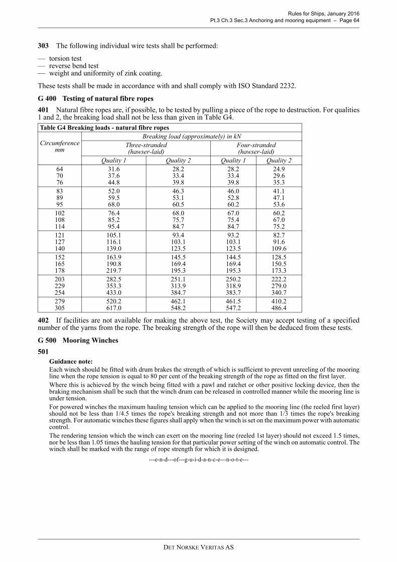
Rules for Ships, January 2016 Pt.3 Ch.3 Sec.3 Anchoring and mooring equipment – Page 64
303 The following individual wire tests shall be performed:
— torsion test— reverse bend test— weight and uniformity of zink coating.
These tests shall be made in accordance with and shall comply with ISO Standard 2232.
G 400 Testing of natural fibre ropes
401 Natural fibre ropes are, if possible, to be tested by pulling a piece of the rope to destruction. For qualities1 and 2, the breaking load shall not be less than given in Table G4.
402 If facilities are not available for making the above test, the Society may accept testing of a specifiednumber of the yarns from the rope. The breaking strength of the rope will then be deduced from these tests.
G 500 Mooring Winches
501 Guidance note:Each winch should be fitted with drum brakes the strength of which is sufficient to prevent unreeling of the mooringline when the rope tension is equal to 80 per cent of the breaking strength of the rope as fitted on the first layer.Where this is achieved by the winch being fitted with a pawl and ratchet or other positive locking device, then thebraking mechanism shall be such that the winch drum can be released in controlled manner while the mooring line isunder tension.For powered winches the maximum hauling tension which can be applied to the mooring line (the reeled first layer)should not be less than 1/4.5 times the rope's breaking strength and not more than 1/3 times the rope's breakingstrength. For automatic winches these figures shall apply when the winch is set on the maximum power with automaticcontrol.The rendering tension which the winch can exert on the mooring line (reeled 1st layer) should not exceed 1.5 times,nor be less than 1.05 times the hauling tension for that particular power setting of the winch on automatic control. Thewinch shall be marked with the range of rope strength for which it is designed.
---e-n-d---of---g-u-i-d-a-n-c-e---n-o-t-e---
Table G4 Breaking loads - natural fibre ropes
Circumference mm
Breaking load (approximately) in kNThree-stranded (hawser-laid)
Four-stranded (hawser-laid)
Quality 1 Quality 2 Quality 1 Quality 2647076
31.637.644.8
28.233.439.8
28.233.439.8
24.929.635.3
838995
52.059.568.0
46.353.160.5
46.052.860.2
41.147.153.6
102108114
76.485.295.4
68.075.784.7
67.075.484.7
60.267.075.2
121127140
105.1116.1139.0
93.4103.1123.5
93.2103.1123.5
82.791.6
109.6152165178
163.9190.8219.7
145.5169.4195.3
144.5169.4195.3
128.5150.5173.3
203229254
282.5353.3433.0
251.1313.9384.7
250.2318.9383.7
222.2279.0340.7
279305
520.2617.0
462.1548.2
461.5547.2
410.2486.4
DET NORSKE VERITAS AS

Rules for Ships, January 2016 Pt.3 Ch.3 Sec.4 Masts and rigging – Page 65
SECTION 4 MASTS AND RIGGING
A. General
A 100 Introduction
101 In this section the requirements to strength and support of masts, derrick posts and standing rigging aregiven.
102 The derricks and the cargo handling gear, are not subject to approval.
A 200 Assumptions
201 The cargo handling systems are assumed only to be operated in harbours or in sheltered waters.
202 The formulae for determining the scantlings of stayed masts, post and standing rigging are based on asymmetrical arrangement of stays and shrouds related to a vertical longitudinal plane through the mast or post.Steel wire ropes for shrouds are assumed with a modulus of elasticity equal to 7.5 · 106 N/mm2.
A 300 Definitions
301 Symbols:
P = load in t which may be lifted by the derrickld = length of derrick in m. Where the working position of the derrick is such that the angle between the
centre line of the derrick and the horizontal always exceeds 15°, ld is taken as the greatest horizontalprojection of the derrick
ls = length of shrouds in mlm = length of mast in m from deck or top of mast house to houndsH = height of derrick heel above deck or top of mast house in ma = athwartship distance in m from the mast to the deck attachment of shroud in question, see Fig.1c = longitudinal distance in m from the mast to the deck attachment of shroud in question, see Fig.1
With reference to a transverse plane through the mast, c shall be taken negative (–) for shrouds fitted onthe same side as the derricks in question and positive (+) for those fitted on the opposite side
e = horizontal distance in m from the mast to the deck attachment of shroud in question, see Fig.1.a0, c0 and e0 refer to the shrouds nearest the transverse plane through the mast. c0 shall not be takengreater than B/4.
Σ = summation of:
a) Load functions for derricks simultaneously serving one hatch.b) Support functions for effective shrouds when loads are as indicated in a), i.e. all shrouds forward or
aft of the mast whichever is opposite to the hatch in question.c) Load functions for derricks simultaneously working outboard.d) Support functions for effective shrouds when loads are as indicated in c), i.e. all shrouds on one side
of the ship, however the attachment to the deck shall not exceed 0.3 B forward or aft of the mast.
Fig. 1Arrangement of shrouds.
DET NORSKE VERITAS AS

Rules for Ships, January 2016 Pt.3 Ch.3 Sec.4 Masts and rigging – Page 66
A 400 Documentation requirements
401 Documentation shall be submitted as required by Table A1.
402 For general requirements to documentation, including definition of the Info codes, see Pt.0 Ch.3 Sec.1.
403 For a full definition of the documentation types, see Pt.0 Ch.3 Sec.2.
B. Materials and welding
B 100 Materials
101 Selection of material grades for plates and sections shall be based on material thickness. NV-steel gradesas given in Table B1 will normally be accepted.
102 The tensile strength of wire ropes intended for shrouds and stays is normally to be minimum 1570 or1770 N/mm2 (see Table G2 of Sec.3) and should not exceed 2200 N/mm2.
103 Material certificates for standing rigging shall be issued by the manufacturer, confirming that thedelivered products are manufactured and tested according to the Rules (see Sec.3 G) or another approvedspecification.
C. Arrangement and support
C 100 Masts and posts
101 Masts and posts shall be efficiently supported and connected to at least two decks or to one deck and amast house top above. If the latter arrangement is adopted, the mast house top shall be of sufficient size andadequately stiffened. A winch house of usual size and scantlings is not considered to meet the requirements.
C 200 Standing rigging
201 The mast or post shall have at least two shrouds on each side of the centre line of the ship. The attachmentof shrouds to mast shall be carefully made so as to reduce torsional strains as far as possible.
202 At fastenings for standing rigging and for guys and topping lifts, the deck shall be securely stiffened andreinforced for the additional loading.
D. Design and scantlings
D 100 General
101 The requirements to diameter d0 and plate thickness t0 for masts and posts given in the following shall bemaintained for a distance not less than 1 m above the derrick heel fitting. Above this level, the diameter and theplate thickness may be gradually reduced to 0.75 d0 and 0.75 t0 at the hounds. Minimum thickness is 7.5 mm.
Table A1 Documentation requirements
Object Documentation type Additional description Info
Masts and rigging
Z030 – Arrangement plan AP
C010 – Design criteria Safe working load. AP
Z250 – Procedure
Information about the operation of the derrick booms, if provided, i.e. how the derricks are intended to be worked, for instance, if more than one derrick is intended to simultaneously serve one hatch. Working position for each provided derrick to be included.
FI
Masts C030 – Detailed drawing Including derrick posts. AP
Rigging C030 – Detailed drawing Including minimum breaking strength. AP
Table B1 Plate material gradesThickness in mm Normal strength structural steel High strength structural steel
t ≤ 20 A A20 < t ≤ 25 B A25 < t ≤ 40 D D
40 < t ≤ 150 E E
DET NORSKE VERITAS AS

Rules for Ships, January 2016 Pt.3 Ch.3 Sec.4 Masts and rigging – Page 67
102 Where masthead span blocks are attached to outriggers, the section modulus of the mast at the level ofthe outrigger shall not be less than:
Z = 120 r Q (cm3)
r = horizontal distance in m from mast to masthead span blocks on outrigger
Σ P = total load in t which may be lifted by the derricks on one side of the centre line of the shipn = 1, 2, 3 etc. for single, double and triple blocks etc., respectively.
103 Masts and posts shall be increased in thickness or reinforced with doubling at the heel, deck and hounds.
D 200 Unstayed masts and posts with derricks
201 The section modulus and moment of inertia of masts and posts with derricks are not, at decks, to be lessthan:
Z = 100 Σ (P l d) (cm3)
Minimum thickness of plating t = 7.5 mm.Masts with outriggers on unusual spread will be specially considered.
D 300 Stayed masts or posts with derricks with a lifting capacity not exceeding 10 t
301 The outer diameter of masts or posts shall not be less than:
302 The plate thickness of masts or posts shall not be less than:t0 = 0.014 d0 mm, minimum 7.5 mm
303 The moment of inertia of masts or posts shall not be less than:
α = 0.5 for derricks with a lifting capacity of 5 t or less= 1.0 for derricks with a lifting capacity of 10 t. Between 5 and 10 t, α is determined by linear
interpolation.
f =
V = breaking strength of shrouds in Nq = tensile strength of shrouds in N/mm2.
D 400 Stayed masts of posts with derricks with a lifting capacity of 10 t or more, but not exceeding 40 t
401 The required outer diameter d0 in mm of masts or posts, measured at deck or top of mast house, isdetermined from the expression:
Q PP
n---------- 1
ld
lm H–---------------
2+ (t)+=
I 240lm
2
lm H–--------------- Pld( ) (cm
4 )=
d0 140 Pld( )13---
(mm)=
I 240lm
2
lm H–--------------- Pld( ) 1500lm
3 fc2
ls3
------α (cm4 )–=
V100q------------ (cm
2 )
DET NORSKE VERITAS AS

Rules for Ships, January 2016 Pt.3 Ch.3 Sec.4 Masts and rigging – Page 68
t0 = plate thickness of mast in mm at diameter d0F = the greater of:
402 The plate thickness of masts or posts is in no place to be less than 7.5 mm.
403 The moment of inertia of masts or posts shall not be less than:
G = the smaller of
404 Section modulus of masts is in general not to be less than:
G = as defined in 403.
405 Where derricks are fitted both forward and aft of the mast, the section modulus is further not to be lessthan:
K =
Σ P1 l d1 and Σ P2 l d2 refer to derricks on either side of a transverse plane through the mast.Σ P1 l d1 shall be the smaller of these products.
D 500 Stayed masts without derricks
501 The diameter of stayed masts without derricks shall not be less than:
d1 = 0.75 d0 (mm) d0 and d1 are the diameter at deck and hounds respectively.
l m1 = length of mast in m measured from deck to hounds.
502 The plate thickness shall not be less than:t = 2.5 + 0.35 l m1 (mm)
D 600 Shrouds
601 Shrouds for masts or posts with derricks shall have breaking strength not less than:
d0t0
100---------- 1.5 P 10lm
2F +≥
fc
ls3
------ and 12--- f 1.7a c+( )
ls3
---------------------------
I 240lm
2
lm H–--------------- Pld 1500lm
3G (cm
4 )–=
fc2
ls3
------ and 14--- f 1.7a c+( )2
ls3
------------------------------
Z80lm
lm H–--------------- Pld
30000lm3
d0-----------------------G (cm
3 ) –=
Z80lm
lm H–--------------- Pld
Klm3
d0------------
fa2
lm3
-------- (cm3 ) –=
24000 1 0.25P1ld1P2ld2
--------------------+
d0
100lm1
3----------------- (mm)=
DET NORSKE VERITAS AS

Rules for Ships, January 2016 Pt.3 Ch.3 Sec.4 Masts and rigging – Page 69
Permanent centre line stays may be included in Σ e when relevant.
602 Shrouds for masts without derricks shall have circumference of steel wire rope not less than 63 mm.
V10.8g0lm
Pld
lm H–( ) 1c0
B-----+
e---------------------------------------------------- ((kN)=
DET NORSKE VERITAS AS

Rules for Ships, January 2016 Pt.3 Ch.3 Sec.5 Lifting appliances and foundations for heavy equipment, deck machinery and towing equipment – Page 70
SECTION 5 LIFTING APPLIANCES AND FOUNDATIONS FOR HEAVY EQUIPMENT, DECK MACHINERY AND TOWING EQUIPMENT
A. Crane and lifting appliances
A 100 Introduction
101 In this sub-section the requirements for strength and support of crane pedestals, support of davits, A-frames and other lifting equipment are given. The requirements are generally applicable to equipment specifiedfor safe working load (SWL) > 30 kN or resulting bending moment at hull fixation > 100 kNm.For davit for survival craft, man over board-boat and work boat, the requirements are applicable regardless ofSWL or resulting bending moment at hull fixation.
102 The crane including pedestal flange and bolts or the lifting gear itself is not subject to approval, unlessclass notation CRANE, DSV or Crane Vessel is requested.
Guidance note:If ILO certification of lifting appliances is requested and DNV shall issue the certificate, approval of documentationwill be required. See DNV Standard for Certification No. 2.22 “Lifting Appliances”.
---e-n-d---of---g-u-i-d-a-n-c-e---n-o-t-e---
103 For the requirements in this section, the following definitions will apply:
— Shipboard cranes are lifting appliances onboard ships and similar units intended for use within harboursareas and when at sea within the cargo deck area.
— Offshore cranes are lifting appliances onboard ships and similar units intended for cargo handling outsidethe deck area at open sea, e.g. loading and discharging of offshore support vessels, barges, etc. or from theseabed.
— Working load (W) is Safe Working Load (SWL) plus the weight of the lifting gear (e.g. hook block). Ref.also DNV Standard for Certification No. 2.22 Ch.2 Sec.2 A200.
104 Design of foundations and supporting structure for lifting appliances in general, e.g. cranes and A-frames, intended for large loads, having a complex arrangement and or comprised by irregular shaped plating,shall be supported by a strength analysis at an extent and content to be agreed before hand with the Society.Calculations shall follow principles outlined in Ch.1 Sec.12.
A 200 Documentation requirements
201 Documentation shall be submitted as required by Table A1.
Table A1 Documentation requirements
Object Documentation type Additional description Info
Cranes
Z030 – Arrangement plan
Including:
- main dimensions - limiting positions of movable parts- location on board during operation and in parked
position.
FI
C010 – Design criteria
Including:
- load charts including safe working loads and corresponding arms
- dynamic coefficients- self-weights and positions of center of gravity
For offshore cranes, also:
- significant wave height (Hs) for operation- load charts showing crane capacity at each given Hs.
FI
DET NORSKE VERITAS AS

Rules for Ships, January 2016 Pt.3 Ch.3 Sec.5 Lifting appliances and foundations for heavy equipment, deck machinery and towing equipment – Page 71
202 For general requirements to documentation, including definition of the Info codes see Pt.0 Ch.3 Sec.1.
203 For a full definition of the documentation types, see Pt.0 Ch.3 Sec.2.
A 300 Materials
301 For pedestal/posts and supporting structures to be used in harbour only, selection of material grade forplates and sections shall be based on Table B1 of Sec.4.
302 When intended for offshore use, the selection of materials for crane pedestal and respective foundationshall be based on the DNV Standard for Certification No. 2.22 “Lifting Appliances”.If not otherwise stated the design temperature TD, for determination of the impact test temperature, shall be –20°C or lower.
303 When a pedestal subjected to bending is not continuous through a deck plating, the following applies:
— either Z-quality material (Pt.2 Ch.2 Sec.1 E) shall be used— or an ultrasonic lamination test of plate before welding, shall be carried out in tension exposed areas (Pt.2
Ch.2 Sec.1 E).
Guidance note:Killed and fine grain treated steel grades with max. sulphur content 0.008% will normally pass the testing.
---e-n-d---of---g-u-i-d-a-n-c-e---n-o-t-e---
304 For welding procedures and details in general, see relevant requirements given in Pt.2 and Pt.3 Ch.1 andCh.2.
A 400 Arrangement
401 Support of heavily loaded crane pedestals shall preferably be provided by at least 2 deck levels. Thesupporting structure shall have continuity and allow safe access for survey of its interior. Reference is made toFig.1 and Fig.2.
Fig. 1Not recommended
Crane pedestals H050 – Structural drawing AP
Crane supporting structures H050 – Structural drawing
Including design loads and reaction forces:
- during operation - in stowed position
AP
Crane stowage arrangements H050 – Structural drawing Including design loads and reaction forces in transit
condition. AP
Crane rails H050 – Structural drawing
Including end buffers and their supports, rack bars and fixation bolts and pads.Including design loads and reaction forces during operation and in stowed positions.
AP
Table A1 Documentation requirements (Continued)
Object Documentation type Additional description Info
DET NORSKE VERITAS AS

Rules for Ships, January 2016 Pt.3 Ch.3 Sec.5 Lifting appliances and foundations for heavy equipment, deck machinery and towing equipment – Page 72
Fig. 2Recommended support
A 500 Design loads
501 The structural strength of the supporting structure (including pedestal) shall be based on a design loadconsisting of the working load (W) multiplied by the dynamic factor “ψ” (specified by the crane designer) plusthe self-weight. However, the dynamic factor shall normally not be taken less than the following:For “shipboard cranes”:– ψ = 1.3For “offshore cranes”:– ψ = 1.3 for 10 kN < W ≤ 2500 kN– ψ = 1.1 for W > 5000 kN.Linear interpolation shall be used for values of W between 2500 kN and 5000 kN.For offshore cranes the design loads for the supporting structure shall be taken as the design loads for the cranemultiplied with an additional offshore safety factor SF1 of 1.1. For offshore cranes with W ≤ 2500 kN, where the operator cabin is attached above the slewing bearing, SF1shall be taken as 1.3.Lifting appliances fitted with shock absorbers may be specially considered.
502 Vertical and horizontal accelerations for the specified sea state. av, at and al to be taken as a safe fractionof the extreme values given in Ch.1 Sec.4 B. Accelerations to be combined as indicated for deck equipment inCh.1 Sec.4 C500.
Guidance note:When the significant wave height HS is known,
may be inserted in the formulae of Ch.1 Sec.4 B.Cw = wave coefficient.
- Wind forces for the specified wind velocity, according to the DNV Standard for Certification No. 2.22 “LiftingAppliances”.
---e-n-d---of---g-u-i-d-a-n-c-e---n-o-t-e---
503 When the transit condition is considered critical, the design loads shall normally be taken as given foridle deck equipment in Ch.1 Sec.4 C500.For vessels with length less than 100 metres, see also Ch.2 Sec.3 B300.For non-compact units wind and icing shall be taken into account as appropriate.Standard ice load for North Sea winter conditions may be taken as 5 cm ice deposit on wind and weatherexposed surfaces.
CW23--- HS=
DET NORSKE VERITAS AS

Rules for Ships, January 2016 Pt.3 Ch.3 Sec.5 Lifting appliances and foundations for heavy equipment, deck machinery and towing equipment – Page 73
Guidance note:For vessel with class notation Offshore Service Vessel+, the loads mentioned above shall be determined as givenin Pt.5 Ch.7 Sec.2 E401.
---e-n-d---of---g-u-i-d-a-n-c-e---n-o-t-e---
504 Supporting structure for survival craft and work boat davits shall be designed for a dynamic coefficienttaken as 2.2.
505 For man-overboard boat davits, the supporting structure shall also be designed to withstand a horizontaltowing force.
A 600 Allowable stresses
601 Allowable stresses in crane pedestals and respective supporting structure shall in principle be taken asfollows:
Normal stresses:160 f1 N/mm2
Shear stresses: 90 f1 N/mm2
The above also applies to supporting structures for davits, A-frames and other similar lifting devices.In way of structures subject to longitudinal hull stresses, the allowable stresses will be especially considered.
A 700 Testing
701 Upon completion of crane foundation, load test shall be carried out in the presence of a DNV surveyor.
B. Foundations for heavy equipment, winches, windlasses and other pulling accessories
B 100 Introduction
101 This sub-section applies to foundations and respective supporting structures for heavy equipment anddeck machinery in general. Foundations and structures covered by C need not comply with this sub-section.
— Heavy equipment: equipment where the static forces exceed 50 kN or resulting static bending moments atdeck exceed 100 kNm.
— Deck machinery: winches, windlasses, chain stoppers, and other similar items, including stern rollers andshark jaws for handling chains of offshore rigs fitted on board offshore support vessels, with breaking loadof the wire or chain > 150 kN, or SWL > 30 kN.
Guidance note:Only windlasses, anchor chain stoppers and equipment related to additional class notations, when specificallymentioned (e.g. towing equipment for vessels with class notation Towing, Anchor Handling or Tug) are includedin scope of classification, requiring plan approval and certification of the equipment by DNV.
---e-n-d---of---g-u-i-d-a-n-c-e---n-o-t-e---
102 For requirements to deck supporting structure of temporary mounted equipment on deck, see DNVClassification Notes No.8 “Conversions of Ships”.
B 200 Documentation requirements
201 Documentation shall be submitted as required by Table B1.
202 For general requirements to documentation, including definition of the Info codes see Pt.0 Ch.3 Sec.1.For a full definition of the documentation types, see Pt.0 Ch.3 Sec.2.
B 300 Design loads and allowable stresses
301 The strength of the foundations and supporting structures shall fulfil the strictest of the followingrequirements as found relevant:
a) Design load to be given by the respective SWL times dynamic coefficient, “ψ”, as specified by designer.“ψ” is however not to be taken less than 1.3.
Table B1 Documentation requirementsObject Documentation type Additional description InfoDeck machinery supporting structure H050 – Structural drawing Including foundation above deck and fixation (bolts,
chocks and shear stoppers). AP
Deck equipment/machinery arrangement Z030 – Arrangement plan
Including main dimensions and design loads(SWL, equipment weight, brake rendering load and wire breaking load) and foot print loads.
FI
DET NORSKE VERITAS AS

Rules for Ships, January 2016 Pt.3 Ch.3 Sec.5 Lifting appliances and foundations for heavy equipment, deck machinery and towing equipment – Page 74
b) Design load to be given by the force in the rope causing the brake to render.c) For winches with constant tension control, design load to be taken as 1.1 times the maximum pulling force.d) For transit condition, see A503.For the above load conditions the allowable stresses are the following:
Normal stresses:160 f1 N/mm2
Shear stresses: 90 f1 N/mm2
e) For winches (e.g. trawl winches) where the rope/equipment can get stuck on the sea bottom or otherwise,the design load shall be equal to the breaking load of the rope.
f) For structure under windlasses and chain stoppers designed for loads as given in Sec.3 F106.For the above load conditions e) and f) the allowable stresses are the following:
Normal stresses:210 f1 N/mm2
Shear stresses: 120 f1 N/mm2
B 400 Securing requirements for fore deck windlasses
401 This subsection gives requirements for the securing of windlasses when fitted under the following threeconditions:
— in ships of length 80 m or more— located on an exposed deck over the forward 0.25 L— the distance between their base and the summer load waterline is less than 0.1 L or 22 m, whichever is the
lesser.
402 These requirements are additional to those appertaining to the anchor and chain performance criteria.
403 Where mooring winches are integral with the anchor windlass, they shall be considered as part of thewindlass.
404 The following pressures and associated areas shall be applied (see Fig.3):
200 kN/m2 normal to the shaft axis and away from the forward perpendicular, over the projected area in thisdirection
150 kN/m2 parallel to the shaft axis and acting both inboard and outboard separately, over the multiple of ftimes the projected area in this direction,
where f is defined as: f = 1+ B/H, but not greater than 2.5
where:B = width of windlass measured parallel to the shaft axisH = overall height of windlass.
405 Forces in the bolts, chocks and stoppers securing the windlass to the deck shall be calculated. Thewindlass is supported by N bolt groups, each containing one or more bolts, see Fig.3.
406 The axial force Ri in bolt group (or bolt) i, positive in tension, may be calculated from: Rxi = Px hxi Ai / Ix
Ryi = Py hyiAi / Iy
andRi = Rxi + Ryi - Rsi
where:
Px = force (kN) acting normal to the shaft axis Py = force (kN) acting parallel to the shaft axis, either inboard or outboard whichever gives the greater
force in bolt group i h = shaft height above the windlass mounting (cm) xi, yi = x and y coordinates of bolt group i from the centroid of all N bolt groups, positive in the direction
opposite to that of the applied force (cm) Ai = cross sectional area of all bolts in group i (cm2) Ix = ΣAi xi
2 for N bolt groups Iy = ΣAi yi
2 for N bolt groups Rsi = static reaction at bolt group i, due to weight of windlass.
DET NORSKE VERITAS AS

Rules for Ships, January 2016 Pt.3 Ch.3 Sec.5 Lifting appliances and foundations for heavy equipment, deck machinery and towing equipment – Page 75
407 Shear forces Fxi, Fyi applied to the bolt group i, and the resultant combined force Fi may be calculatedfrom:
Fxi = (Px – α g M) / NFyi = (Py – α g M) / N
andFi = (Fxi
2 + Fyi2)0.5
where:
α = coefficient of friction (0.5) M = mass of windlass (tonnes) g = gravity (9.81 m/sec2) N = number of bolt groups.
408 Axial tensile and compressive forces in 406 and lateral forces in 407 shall also be considered in thedesign of the supporting structure.
409 Tensile axial stresses in the individual bolts in each bolt group i shall be calculated. The horizontal forcesFxi and Fyi shall normally be reacted by shear chocks. Where “fitted” bolts are designed to support these shearforces in one or both directions, the von Mises' equivalent stresses in the individual bolts shall be calculated,and compared to the stress under proof load. Where pourable resins are incorporated in the holding downarrangements, due account shall be taken in the calculations. The safety factor against bolt proof strength shall be not less than 2.0.(IACS UR S27)
DET NORSKE VERITAS AS
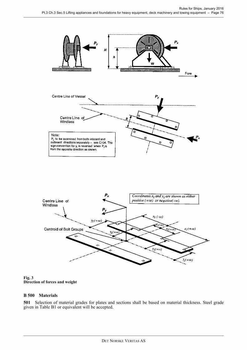
Rules for Ships, January 2016 Pt.3 Ch.3 Sec.5 Lifting appliances and foundations for heavy equipment, deck machinery and towing equipment – Page 76
Fig. 3Direction of forces and weight
B 500 Materials
501 Selection of material grades for plates and sections shall be based on material thickness. Steel gradegiven in Table B1 or equivalent will be accepted.
DET NORSKE VERITAS AS

Rules for Ships, January 2016 Pt.3 Ch.3 Sec.5 Lifting appliances and foundations for heavy equipment, deck machinery and towing equipment – Page 77
502 Deck doublers are generally not acceptable if tension perpendicular to deck occurs.
C. Shipboard fittings and supporting hull structures associated with towing and mooring on conventional vessels
C 100 Introduction
101 The requirements in this sub-section apply to the design and construction of shipboard fittings andrespective supporting structures, used for normal towing (at bow, sides and stern) and mooring operations onconventional vessels.
102 For the purpose of applying this sub-section, the following definitions apply:
— conventional vessels means new displacement-type vessels of 500 GT and above, excluding high speedcraft, and offshore units of all types.
— shipboard fittings means those components limited to the following: bollards and bitts, fairleads, standrollers, chocks used for the normal mooring of the vessel and the similar components used for the normaltowing of the vessel. Other components such as capstans, winches, etc. are not covered by the requirementsin this sub-section. Any weld, bolt or equivalent device connecting the shipboard fitting to the supportingstructure is part of the shipboard fitting and subject to the Industry standard applicable to this shipboardfitting.
— supporting hull structures mean that part of the ship structure on/in which the shipboard fitting is placedand which is directly subjected to the forces exerted on the shipboard fitting. The supporting hull structureof capstans, winches, etc. used for the normal towing and mooring operations mentioned above is alsosubject to the requirements in this sub-section.
— Industry standard means international standard (ISO, etc.) or standards issued by national association suchas DIN or JMSA, etc. which are recognized in the country where the ship is built.
103 Arrangement of emergency towing for tankers of 20 000 tonnes deadweight and above, including oiltankers, chemical tankers and gas carriers, shall comply with requirements in Pt.5 Ch.3 Sec.2 C500.Shipboard fittings being part of emergency towing procedure, as required by SOLAS II-1/3-4 for passengerand cargo ships, shall comply with C500.
104 Equipment and supporting structures covered by separate class notations like e.g. “Tug”, “OffshoreService Vessel” and “Escort” are not covered by the below requirements, but are to comply with therequirements in the respective sections (e.g. Pt.5 Ch.7 Secs.2, 3 and 15).
Table B1 Plate material gradesThickness (mm) Normal strength structural steel High strength structural steel
t ≤ 40 A A40 < t ≤ 150 B A
DET NORSKE VERITAS AS

Rules for Ships, January 2016 Pt.3 Ch.3 Sec.5 Lifting appliances and foundations for heavy equipment, deck machinery and towing equipment – Page 78
C 200 Documentation requirements
201 Documentation shall be submitted as required by Table C1.
202 For vessels with increased number of mooring lines to compensate for reduced breaking strength asoutlined in footnote to Sec.3 Table C1, the “Towing and mooring arrangement plan” shall also show thenumber of mooring lines together with the breaking strength of each mooring line.
203 The “Towing and mooring arrangement plan” shall be available on board for the guidance of the Master.
204 For general requirements to documentation, including definition of the Info codes see Pt.0 Ch.3 Sec.1.
205 For a full definition of the documentation types, see Pt.0 Ch.3 Sec.2.
C 300 General
301 Shipboard fittings for towing and mooring shall be located on stiffeners and /or girders, which are partof the deck structure, so as to facilitate efficient distribution of the load. Other arrangements may be accepted(for Panama chocks, etc.) provided the strength is confirmed adequate for the intended service.
302 The deck strengthening beneath shipboard fittings shall be effectively arranged for any variation ofdirection (horizontally and vertically) of the design loads acting through the arrangement of connection to theshipboard fittings.
303 Strength calculations shall be based on net scantlings after deduction of corrosion addition. For thispurpose, the total corrosion addition, tk, in mm, for the supporting structure is normally not to be less than thefollowing values:
— Ships covered by IACS Common Structural Rules for Bulk Carriers and Oil Tankers: Total corrosionadditions defined in these rules
— Other ships: 2.0 mm.
304 The selection of shipboard fittings shall be made by the shipyard normally in accordance with an industrystandard (e.g. ISO 13795 Ships and marine technology - Ship's mooring and towing fittings - Welded steelbollards for sea-going vessels) accepted by the Society.
305 When a shipboard fitting is not selected from an accepted industry standard, the design is subject toapproval. The design load used to assess its strength and its attachment to the ship shall be in accordance therelevant requirements in C400 and C500, for towing and mooring respectively.
306 Allowable stresses for fittings according to C305 and for all supporting structures are:
No stress concentration factors need to be taken into account.Normal stress shall be taken as the sum of the bending and axial stress with the corresponding shear stressacting perpendicular to the normal stress.
307 The SWL of each shipboard fitting used for towing or mooring shall be marked by weld bead orequivalent.
Table C1 Documentation requirementsObject Documentation type Additional description Info
Towing and mooring arrangements Z030 – Arrangement plan
Plan providing information for each item regarding:
- location on the ship- fitting types - dimensions- safe working load- maximum breaking strength of the towing and mooring
lines - the purpose (mooring / harbour towing etc.) - manner of applying the lines including limiting fleet angles.
FI
Emergency towing arrangement
Z030 – Arrangement plan
Plan providing information for each item regarding:
- location on the ship- fitting type - dimensions- safe working load- maximum breaking strength of the towing lines - manner of applying the towing line including limiting fleet
angles
FI
Z250 – Procedure Covering SOLAS II-1/3-4. FI
Allowable normal stress: 100% of the specified minimum yield point of the materialAllowable shear stress: 60% of the specified minimum yield point of the material
DET NORSKE VERITAS AS

Rules for Ships, January 2016 Pt.3 Ch.3 Sec.5 Lifting appliances and foundations for heavy equipment, deck machinery and towing equipment – Page 79
308 The method of using the towing lines and mooring lines shall be defined in the “Towing and mooringarrangement plan”.
309 The acting point of the towing/ mooring forces on deck fittings shall be taken at the attachment point ofa towing/ mooring line or at a change in its direction.
C 400 Towing
401 Unless greater safe working load (SWL) of shipboard fittings is specified, the minimum design load tobe used is the following value of (1) or (2), whichever is applicable:
(1) for normal towing operations (e.g. in harbour / manoeuvring), 1.25 times the intended maximum towingload (e.g. static bollard pull) as indicated on the “Towing and mooring arrangement plan”.
(2) for other towing service, the nominal breaking strength of the towing line according to values given inSec.3 Table C1, for the ship's corresponding equipment number.
For the selection of the towing lines, the projected area including maximum stacks of deck cargoes shall beconsidered in the calculation of the equipment number. The breaking loads of towing lines given as guidancein Sec.3 Table C1 is the design load to be applied to the shipboard fittings and supporting hull structure.The design load shall be applied through the tow line according to the arrangement shown on the “Towing andmooring arrangements plan”.
Guidance note:It is not required to have equipment installed for the sole purpose of towing. However, in case towing equipment isspecified in the “Towing and mooring arrangement plan” requirements stated in C400 are applicable. Shipboardfittings only to be used for emergency towing should be in accordance with C500.
---e-n-d---of---g-u-i-d-a-n-c-e---n-o-t-e---
402 The method of application of the design load to the fittings and supporting hull structures shall be takeninto account, such that the total load need not be more than twice the design load, i.e. no more than one turn ofone line (see figure below).
403 The following requirements apply to the definition of the Safe Working Load (SWL):
1) The SWL used for normal towing operations (e.g. harbour / manoeuvring) is not to exceed 80% of thedesign load per 401(1) and the SWL used for other towing operations is not to exceed the design load per401(2). For fittings used for both normal and other towing operations, the greater of the design loads givenin 401 shall be used.
2) The above requirements on SWL apply for a single post basis (no more than one turn of one cable).
C 500 Mooring
501 For the mooring shipboard fittings and respective supporting hull structures, the following will apply todefinition of the design load:
1) Unless greater safe working load (SWL) of mooring fittings are specified by the applicant, the design loadto be applied to the fittings and supporting hull structures shall be 1.25 times the breaking strength of themooring line according to values given in Sec.3 Table C1 as guidance for the ship's correspondingequipment number.
2) The design load to be applied to supporting hull structures for mooring winches, etc. shall be 1.25 times theintended maximum brake holding load and, for capstans, 1.25 times the maximum hauling-in force.
3) The design load shall be applied through the mooring line according to the arrangement shown on the“Towing and mooring arrangements plan”.
4) The method of application of the design load to the fittings and supporting hull structures shall be taken
DET NORSKE VERITAS AS
Rules for Ships, January 2016 Pt.3 Ch.3 Sec.5 Lifting appliances and foundations for heavy equipment, deck machinery and towing equipment – Page 80
into account such that, the total load need not be more than twice the design load specified in 1) above, i.e.no more than one turn of one line.
5) When a specific SWL is applied for a shipboard fitting at the request of the applicant, by which the designload will be greater than the above minimum values, the strength of the fitting shall be designed using thisspecific design load.
6) Design load for shipboard fittings included in the emergency towing procedure required by SOLAS II-1/3-4, shall be taken not less than strong point capacity specified in the procedure. The capacity is assumed tobe not less than 1.25 times the safe working load (SWL).
For the purpose of defining breaking strength of the mooring line, its selection shall be based on equipmentnumber calculated considering the projected area including maximum stacks of deck cargoes. The breakingloads of mooring lines given as guidance in Sec.3 Table C1 shall be used for determining the design load to beapplied to the shipboard fittings and supporting hull structure.
502 The following requirements apply to the definition of the Safe Working Load (SWL) for the mooringfittings:
1) The SWL is not to exceed 80% of the design load given in C501.2) The above requirements on SWL apply for a single post basis (no more than one turn of one cable).
(IACS UR A2)
C 600 Materials
601 The material in deck fittings and supporting structure shall be at least NVA or equivalent.Casting in mooring and towing equipment shall be of weldable quality.The material in foundation for emergency towing equipment shall comply with requirement in Sec.4 Table B1.
DET NORSKE VERITAS AS

Rules for Ships, January 2016 Pt.3 Ch.3 Sec.6 Openings and closing appliances – Page 81
SECTION 6 OPENINGS AND CLOSING APPLIANCES
A. General
A 100 Application
101 In this section the requirements for the arrangement of openings and closing appliances have beencollected. The closing appliances are in general to have strength at least corresponding to the required strengthof that part of the hull in which they are fitted.
102 This section applies to all ships above 24 m in length, with the following exceptions:
— pleasure yachts not engaged in trade— fishing vessels, see Pt.5 Ch.6 Sec.6.
For ships less than 24 m in length this section applies as practicable.
A 200 Definitions
201 Symbols:
L = rule length in m 1)
B = rule breadth in m 1)
CB = rule block coefficient 1)
t = plate thickness in mm. 1)
Z = rule section modulus in cm3 of stiffeners and simple girderska = correction factor for aspect ratio of plate field
= (1.1 – 0.25 s/ l)2
= maximum 1.0 for s/ l = 0.4= minimum 0.72 for s/ l = 1.0
s = stiffener spacing in m, measured along the platingl = stiffener span in m, measured along the topflange of the member. For definition of span point, see Ch.1
Sec.3 C100. For curved stiffeners l may be taken as the cord lengthS = girder span in m. For definition of span point, see Ch.1 Sec.3 C100f1 = material factor
= 1.0 for NV-NS steel 2)
= 1.08 for NV-27 steel 2)
= 1.28 for NV-32 steel 2)
= 1.39 for NV-36 steel 2)
= 1.47 for NV-40 steel 2)
tk = corrosion addition as specified in Ch.1 Sec.2wk = section modulus correction factor in tanks, see Ch.1 Sec.3 C1004σ = nominal allowable bending stress in N/mm2 due to lateral pressureτ = nominal allowable shear stress in N/mm2 due to lateral loadsp = design pressure in kN/m2 as given for the various structures.
1) See Ch.1 Sec.1 B.
2) For details see Ch.1 Sec.2 B and C.
202 TermsPositionFor the purpose of the Regulations, two positions of hatchways, doorways and ventilators are defined asfollows:
Position 1 - Upon exposed freeboard and raised quarter decks, and upon exposed superstructure decks situatedforward of a point located a quarter of the ship's length from the forward perpendicular.
Position 2 - Upon exposed superstructure decks situated abaft a quarter of the ship's length from the forwardperpendicular and located at least one standard height of superstructure above the freeboard deck.Upon exposed superstructure decks situated forward of a point located a quarter of the ship'slength from the forward perpendicular and located at least two standard heights of superstructureabove the freeboard deck.
(ICLL Reg.13)
DET NORSKE VERITAS AS

Rules for Ships, January 2016 Pt.3 Ch.3 Sec.6 Openings and closing appliances – Page 82
Freeboards greater than minimumWhere freeboards are required to be increased, because of such consideration as strength, location of shell orside scuttles or other reasons, then:
a) The height of doors sills, hatchway coamings, sills of machinery space openings, miscellaneous openings,ventilators and air pipes
b) the scantlings of hatch coversc) freeing arrangements and means for protection of crewd) windows and side scuttles
on the actual freeboard deck may be as required for a superstructure deck, provided the summer freeboard issuch that the resulting draught will not be greater than that corresponding to the minimum freeboard calculatedfrom an assumed freeboard deck situated at a distance equal to a standard superstructure height below the actualfreeboard deck. Similar considerations may be given in cases of draught limitation on account of bow height.Ship typesThe basic ship types are as follows:
Type "A" Ships designed solely for the carriage of liquid cargoType "B" Cargo ship other than “A”, with steel weathertight hatch coversType "B-100" "B-60"Cargo ship of type "B" with reduced freeboard on account of their ability to survive
damageType "B+" Cargo ship with increased freeboard on account of hatch cover arrangementWeathertight means that in any sea condition water will not penetrate into the vessel.Watertight means capable of preventing the passage of water through the structure under a head of water forwhich the surrounding structure is designed.Ro-ro passenger ship is a passenger ship with ro-ro spaces or special category spaces.Ro-ro spaces are spaces not normally subdivided in any way and normally extending to either a substantiallength or the entire length of the ship in which motor vehicles with fuel in their tanks for their own propulsionand/or goods (packaged or in bulk, in or on rail or road cars, vehicles (including road or rail tankers), trailers,containers, pa llets, demountable tanks or in or on similar stowage units or other receptacles) can be loaded andunloaded normally in a horizontal direction.Special category spaces are those enclosed spaces above or below the bulkhead deck, into and from which vehiclescan be driven and to which passengers have access. Special category spaces may be accommodated on more thanone deck provided that the total overall clear height for vehicles does not exceed 10 m.Freeboard, freeboard deck and superstructure, see Ch.1 Sec.1 B200.
A 300 Documentation requirements
301 Documentation shall be submitted as required by Table A1.
Table A1 Documentation requirementsObject Documentation type Additional description InfoExternal watertight integrity
B200 – Freeboard plan AP
Cargo hatches C030 – Detailed drawing Including covers and opening, closing, sealing, securing and locking devices.
AP
Shell doors and ramps (bow, side and stern as applicable)
C030 – Detailed drawing Including securing devices. API200 – Control and monitoring system documentation
Shell doors control and monitoring system.
AP
I200 – Control and monitoring system documentation
Water leakage monitoring system.
AP
Z160 – Operation manual APZ180 – Maintenance manual AP
Service hatches C030 – Detailed drawing APManholes Z030 – Arrangement plan FIScuppers S010 – Piping diagram AP
DET NORSKE VERITAS AS

Rules for Ships, January 2016 Pt.3 Ch.3 Sec.6 Openings and closing appliances – Page 83
302 For general requirements to documentation, including definition of the Info codes, see Pt.0 Ch.3 Sec.1.
303 For a full definition of the documentation types, see Pt.0 Ch.3 Sec.2.
A 400 On board documentation
401 The operation and maintenance manuals for the shell doors shall be provided on board.
A 500 Testing
501 All weathertight/watertight doors and hatch covers shall be function tested.
502 For ships exclusively intended for the carriage of containers in the cargo holds, for which an exemptionto the ICLL, Reg.16 (see E and F) has been granted by the Flag Administration, and which complies with therequirements given in Pt.5 Ch.2 Sec.6 G, the required testing for weathertightness given in Pt.2 Ch.3 Sec.8 maybe dispensed with.
503 If non weathertight hatch covers are fitted in accordance with 402, this will be noted in the main letter ofapproval with the implication that hose testing for weathertightness in accordance with Pt.2 Ch.3 Sec.8 will notbe carried out.
504 Doors and hatch covers which become immersed by an equilibrium or an intermediate water plane in adamaged condition are to be subjected to a hydrostatic pressure test. The head of water used for the pressuretest shall correspond at least to the head measured from the lower edge of the door opening, at the location inwhich the door is to be fitted in the vessel, to the most unfavourable damage waterplane. The acceptance criteriafor the test is no leakage. For large doors, above 6 m2, structural analysis may be accepted in lieu of pressure testing. Where such doorsutilise gasket seals, a prototype pressure test of the gasket seal to confirm that the compression of the gasketmaterial is capable of accommodating maximum deflection, revealed by the structural analysis, is to be carriedout. After installation of such door or hatch, the initial gasket compression is to be documented.
A 600 Certificate requirements
601 Components shall be certified as required by Table A2.
602 For a definition of the certificate types, see Pt.1 Ch.1 Sec.4 B.
Internal watertight doors
Z030 – Arrangement plan Including for each door: Size, design principle (sliding, hinged), pressure rating and fire rating. Including remote control positions.
AP
I200 – Control and monitoring system documentation
Internal watertight doors control and monitoring system.
AP
Retractable bottom equipment
H050 – Structural drawing Foundations including watertight boundaries.
AP
H050 – Structural drawing Supporting structures. APZ030 – Arrangement plan Including resulting loads acting
on the supporting structures, and details of sealings.
FI
Box coolers H050 – Structural drawing Foundations including watertight boundaries.
AP
H050 – Structural drawing Supporting structures. APZ030 – Arrangement plan Including details of sealings. FI
Engine rooms Z240 – Calculation report For vessels with periodically unmanned machinery space: Filling time calculation, see K400.
FI
Table A2 Certificate requirementsObject Certificate typeInternal watertight doors control and monitoring system NV-P DNV product certificateShell doors control and monitoring system NV-P DNV product certificate
Table A1 Documentation requirements (Continued)Object Documentation type Additional description Info
DET NORSKE VERITAS AS
Rules for Ships, January 2016 Pt.3 Ch.3 Sec.6 Openings and closing appliances – Page 84
B. Access openings in superstructures and freeboard deck
B 100 Doors
101
1) All access openings in bulkheads at ends of enclosed superstructures shall be fitted with doors of steel orother equivalent material, permanently and strongly attached to the bulkhead, and framed, stiffened andfitted so that the whole structure is of equivalent strength to the unpierced bulkhead and weathertight whenclosed. The means for securing these doors weathertight shall consist of gaskets and clamping devices orother equivalent means and shall be permanently attached to the bulkhead or to the doors themselves, andthe doors shall be so arranged that they can be operated from both sides of the bulkhead.
2) Except as otherwise provided in these Regulations, the height of the sills of access openings in bulkheadsat ends of enclosed superstructures shall be at least 380 millimetres above the deck.
(ICLL Reg.12)
102
a) Doors should generally open outwards to provide additional security against the impact of the sea. Doorswhich open inwards shall be especially approved.
b) Portable sills should be avoided. However, in order to facilitate the loading/unloading of heavy spare parts orsimilar, portable sills may be fitted on the following conditions:
i) They shall be installed before the ship leaves port.ii) Sills shall be gasketed and fastened by closely spaced through bolts.iii) Whenever the sills are replaced after removal, the weathertightness of the sills and the related doors
shall be verified by hose testing. The dates of removal, replacing and hose testing shall be recorded inthe ship's log book.
(IACS UI LL5)
103 Weathertight doors as specified above shall be fitted in all access openings in:
— bulkheads at ends of superstructures— bulkheads of deckhouses on freeboard deck protecting openings in the freeboard deck— companionways on freeboard deck and superstructure deck— bulkheads of deckhouses on superstructure deck protecting openings in the superstructure deck— companionways and bulkheads of deckhouse upon another deckhouse on freeboard deck protecting
openings in the freeboard deck.
104 For weathertight doors the minimum required door blade thickness corresponding to lateral pressureshall be calculated by the following formula:
The section modulus requirement for stiffeners is given by:
assuming simply supported ends.
105 The number of the cleats is to comply with ISO6042(1998). The cleats may be individual or centrally operated.
106 A hinged watertight door that opens inwards is acceptable in lieu of a weathertight door that opensoutwards.
B 200 Sill heights
201 Openings as mentioned in 100 are in general to have sill heights not less than 380 mm.The following openings in position 1 shall have sill heights not less than 600 mm:
— Companionways— where access is not provided from the deck above: Openings in poop frontbulkhead, bulkheads at ends of
midships superstructures and bulkheads at ends and sides of deckhouses— openings in forecastle end bulkhead covering entrance to space below the deck— openings in engine casings.
t1.58ka s p
f1
----------------------------- (mm)=
Z0.8 l
2s p
f1
--------------------- (cm3
)=
DET NORSKE VERITAS AS
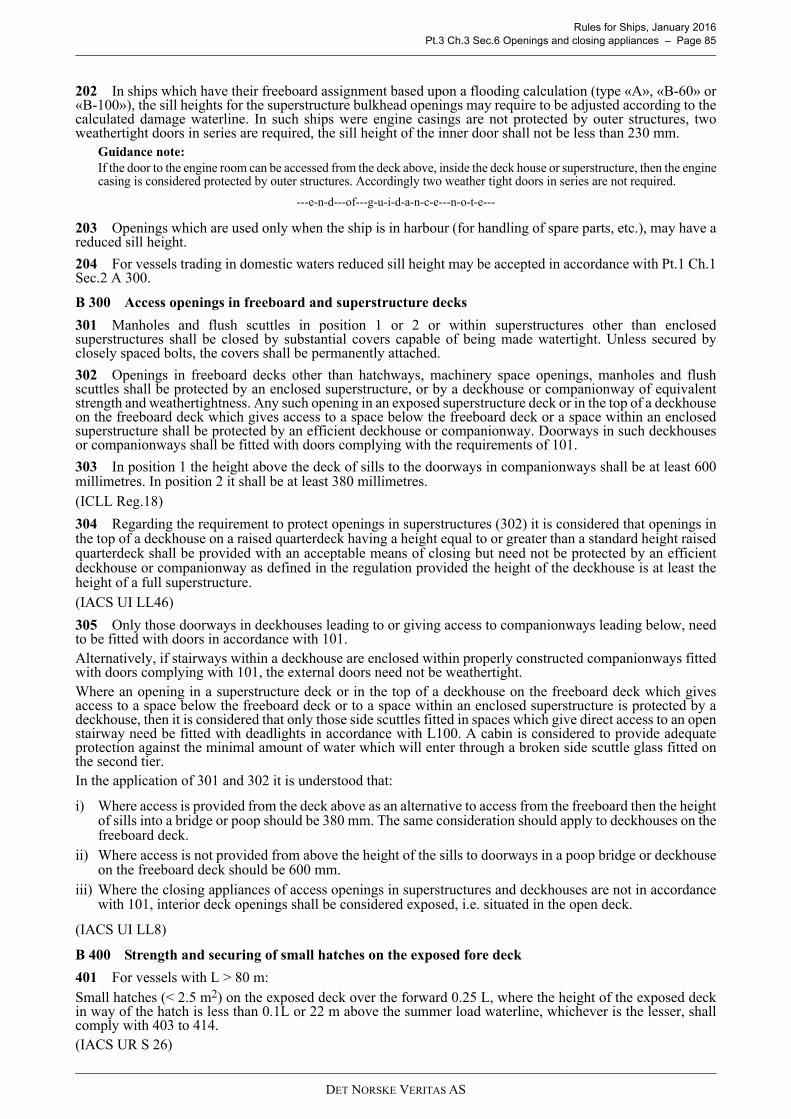
Rules for Ships, January 2016 Pt.3 Ch.3 Sec.6 Openings and closing appliances – Page 85
202 In ships which have their freeboard assignment based upon a flooding calculation (type «A», «B-60» or«B-100»), the sill heights for the superstructure bulkhead openings may require to be adjusted according to thecalculated damage waterline. In such ships were engine casings are not protected by outer structures, twoweathertight doors in series are required, the sill height of the inner door shall not be less than 230 mm.
Guidance note:If the door to the engine room can be accessed from the deck above, inside the deck house or superstructure, then the enginecasing is considered protected by outer structures. Accordingly two weather tight doors in series are not required.
---e-n-d---of---g-u-i-d-a-n-c-e---n-o-t-e---
203 Openings which are used only when the ship is in harbour (for handling of spare parts, etc.), may have areduced sill height.
204 For vessels trading in domestic waters reduced sill height may be accepted in accordance with Pt.1 Ch.1Sec.2 A 300.
B 300 Access openings in freeboard and superstructure decks
301 Manholes and flush scuttles in position 1 or 2 or within superstructures other than enclosedsuperstructures shall be closed by substantial covers capable of being made watertight. Unless secured byclosely spaced bolts, the covers shall be permanently attached.
302 Openings in freeboard decks other than hatchways, machinery space openings, manholes and flushscuttles shall be protected by an enclosed superstructure, or by a deckhouse or companionway of equivalentstrength and weathertightness. Any such opening in an exposed superstructure deck or in the top of a deckhouseon the freeboard deck which gives access to a space below the freeboard deck or a space within an enclosedsuperstructure shall be protected by an efficient deckhouse or companionway. Doorways in such deckhousesor companionways shall be fitted with doors complying with the requirements of 101.
303 In position 1 the height above the deck of sills to the doorways in companionways shall be at least 600millimetres. In position 2 it shall be at least 380 millimetres.(ICLL Reg.18)
304 Regarding the requirement to protect openings in superstructures (302) it is considered that openings inthe top of a deckhouse on a raised quarterdeck having a height equal to or greater than a standard height raisedquarterdeck shall be provided with an acceptable means of closing but need not be protected by an efficientdeckhouse or companionway as defined in the regulation provided the height of the deckhouse is at least theheight of a full superstructure. (IACS UI LL46)
305 Only those doorways in deckhouses leading to or giving access to companionways leading below, needto be fitted with doors in accordance with 101.Alternatively, if stairways within a deckhouse are enclosed within properly constructed companionways fittedwith doors complying with 101, the external doors need not be weathertight.Where an opening in a superstructure deck or in the top of a deckhouse on the freeboard deck which givesaccess to a space below the freeboard deck or to a space within an enclosed superstructure is protected by adeckhouse, then it is considered that only those side scuttles fitted in spaces which give direct access to an openstairway need be fitted with deadlights in accordance with L100. A cabin is considered to provide adequateprotection against the minimal amount of water which will enter through a broken side scuttle glass fitted onthe second tier.In the application of 301 and 302 it is understood that:
i) Where access is provided from the deck above as an alternative to access from the freeboard then the heightof sills into a bridge or poop should be 380 mm. The same consideration should apply to deckhouses on thefreeboard deck.
ii) Where access is not provided from above the height of the sills to doorways in a poop bridge or deckhouseon the freeboard deck should be 600 mm.
iii) Where the closing appliances of access openings in superstructures and deckhouses are not in accordancewith 101, interior deck openings shall be considered exposed, i.e. situated in the open deck.
(IACS UI LL8)
B 400 Strength and securing of small hatches on the exposed fore deck
401 For vessels with L > 80 m:Small hatches (< 2.5 m2) on the exposed deck over the forward 0.25 L, where the height of the exposed deckin way of the hatch is less than 0.1L or 22 m above the summer load waterline, whichever is the lesser, shallcomply with 403 to 414.(IACS UR S 26)
DET NORSKE VERITAS AS

Rules for Ships, January 2016 Pt.3 Ch.3 Sec.6 Openings and closing appliances – Page 86
402 Hatches designed for use as emergency escape shall comply with these requirements, except 414.In 407, option (iii) shall be used (for emergency escapes).
403 For small rectangular steel hatch covers, the plate thickness, stiffener arrangement and scantlings shallbe in accordance with Table B1, and Fig 1. Stiffeners, where fitted, shall be aligned with the metal-to-metalcontact points, required in 409, see Fig.1. Primary stiffeners shall be continuous. All stiffeners shall be weldedto the inner edge stiffener, see Fig.2.
404 The upper edge of the hatchway coamings shall be suitably reinforced by a horizontal section, normallynot more than 170 to 190 mm from the upper edge of the coamings.
405 For small hatch covers of circular or similar shape, the cover plate thickness and reinforcement shall beaccording to the requirements of E.
406 For small hatch covers constructed of materials other than steel, the required scantlings shall provideequivalent strength.
407 Small hatches located on exposed fore deck shall be fitted with primary securing devices such that theirhatch covers can be secured in place and weather tight by means of a mechanism employing any one of thefollowing methods:
i) butterfly nuts tightening onto forks (clamps)ii) quick acting cleats, or iii) central locking device.
For emergency escape hatches the central locking device shall be of a quick-acting type operable from bothsides of the hatch cover. (IACS UR S26)
408 Dogs (twist tightening handles) with wedges are not acceptable.
409 The hatch cover shall be fitted with a gasket of elastic material. This shall be designed to allow a metalto metal contact at a designed compression and to prevent over compression of the gasket by green sea forcesthat may cause the securing devices to be loosened or dislodged. The metal-to-metal contacts shall be arrangedclose to each securing device in accordance with Fig.1, and of sufficient capacity to withstand the bearing force.
410 The primary securing method shall be designed and manufactured such that the designed compressionpressure is achieved by one person without the need of any tools.
411 For a primary securing method using butterfly nuts, the forks (clamps) shall be of robust design. Theyshall be designed to minimize the risk of butterfly nuts being dislodged while in use; by means of curving theforks upward, a raised surface on the free end, or a similar method. The plate thickness of unstiffened steel forksshall not be less than 16 mm. An example arrangement is shown in Fig.2.
412 For small hatch covers located on the exposed deck forward of the fore-most cargo hatch, the hinges shallbe fitted such that the predominant direction of green sea will cause the cover to close, which means that thehinges are normally to be located on the fore edge.
413 On small hatches located between the main hatches, for example between Nos. 1 and 2, the hinges shallbe placed on the fore edge or outboard edge, whichever is practicable for protection from green water in beamsea and bow quartering conditions.
414 Small hatches on the fore deck shall be fitted with an independent secondary securing device e.g. bymeans of a sliding bolt, a hasp or a backing bar of slack fit, which is capable of keeping the hatch cover in place,even in the event that the primary securing device became loosened or dislodged. It shall be fitted on the sideopposite to the hatch cover hinges.(IACS UR S26)
Table B1 Scantling for small steel hatch covers on the fore deckNominal size (mm × mm) Cover plate thickness (mm) Primary stiffeners Secondary stiffeners
Flatbar (mm × mm); number630 × 630 8 – –630 × 830 8 100 × 8; 1 –830 × 630 8 100 × 8; 1 –830 × 830 8 100 × 10; 1 –
1030 × 1030 8 120 × 12; 1 80 × 8; 21330 × 1330 8 150 × 12; 2 100 × 10; 2
DET NORSKE VERITAS AS
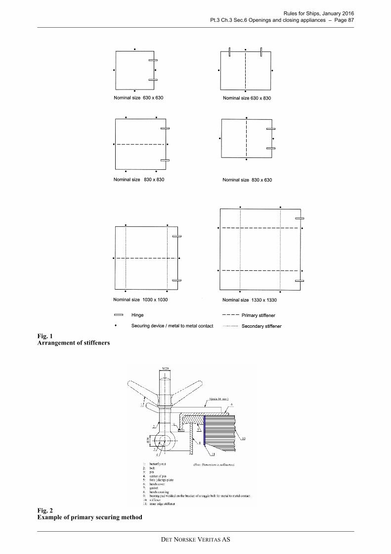
Rules for Ships, January 2016 Pt.3 Ch.3 Sec.6 Openings and closing appliances – Page 87
Fig. 1Arrangement of stiffeners
Fig. 2Example of primary securing method
DET NORSKE VERITAS AS

Rules for Ships, January 2016 Pt.3 Ch.3 Sec.6 Openings and closing appliances – Page 88
C. Side and stern doors
C 100 General.
101 These requirements cover cargo and service doors in the ship side (abaft the collision bulkhead) and stern area,below the freeboard deck and in enclosed superstructures. For requirements for bow doors, see Pt.5 Ch.2 Sec.3.
102 The side and stern doors shall be fitted as to ensure tightness and structural integrity commensurate withtheir location and the surrounding structure.The number of such openings shall be the minimum compatible with the design and proper working of the ship.All external openings leading to compartments assumed intact in the damage analysis, which are below thefinal damage waterline, are required to be watertight.(2006/05 SOLAS Am/II-1/B-2/15-1)
103 The lower edge of any cargo or service door, if located below the freeboard deck, shall not be below aline drawn parallel to the freeboard deck at side, which at its lowest point is 230 mm above the upper edge ofthe uppermost load line. Special consideration shall be given to preventing the spread of any leakage water overthe deck. A flatbar welded to the deck and provision of scuppers would be an acceptable arrangement.
104 Where the sill of any cargo or service door is below the line defined in C103, the arrangements willrequire to be specially considered to ascertain that the safety of the ship is in no way impaired. It is consideredthat the fitting of a second door of equivalent strength ad watertightness is one acceptable arrangement. In thatcase leakage detection device should be provided in the compartment between the two doors. Further, drainageof this compartment to the bilges controlled by an easily accessible screw down valve, should be arranged. Theouter door should preferably open outwards. (IACS UI LL21)
105 Doors should preferably open outwards.
106 Terms:Cleats: Devices for pre-compression of packings and steel to steel contact.Supports: Load carrying devices designed for transfer of acting forces from door structures to hull structures.Locking arrangement: Preventive measures ensuring that cleats and supports as applicable always remain inposition when engaged.
C 200 Structural arrangement
201 Door openings in the shell shall have well rounded corners and adequate compensation shall be arrangedwith web frames at sides and stringers or equivalent above and below.
202 Doors shall be adequately stiffened, and means shall be provided to prevent movement of the doors whenclosed. Adequate strength shall be provided in the connections of the lifting/manoeuvring arms and hinges tothe doors structures and to the ship structure.
203 A ≥ 12 m2 Doors with light opening area shall be such that the sea pressure is transferred directly to thehull coamings.
204 For doors with light opening area A < 12 m2 securing bolts or similar devices may be accepted as carriersof sea pressure to the coamings, if an arrangement as required in 203 is not feasible.
205 If a door is divided into separate sections, each section shall have full strength independent of the othersections.
206 Where doors also serve as vehicle ramps, the design of the hinges should take into account the ship angleof trim and heel, which may result in uneven loading on the hinges.
C 300 Design loads
301 The design sea pressure is given by:p = ( pdp – (4 + 0.2 ks) h0 ) 1)
minimum 6.25 + 0.025 L (kN/m2)or
p = 10 hb2), whichever is the largest.
pdp, ks = as given in Ch.1 Sec.4 C201h0 = vertical distance in m from the load point to the waterline at draught T.hb = vertical distance in metres from the load point to the deepest equilibrium or intermediate waterline in
damaged condition, obtained from applicable damage stability calculations.
DET NORSKE VERITAS AS
Rules for Ships, January 2016 Pt.3 Ch.3 Sec.6 Openings and closing appliances – Page 89
For ships with service restrictions p may be reduced with the percentages given in Ch.1 Sec.4 B202. CW shouldnot be reduced.
302 The design force for securing bolts and other closing devices, supporting members and surroundingstructure is given by:
F1 = A pe 103 + FP (N)or
F2 = F0 + 10 W + FP (N)F1 is applicable for ports opening inwards.F2 is applicable for ports opening outwards.
pe = external design pressure p according to 301, minimum 25 kN/m2
FP = total packing force in NF0 = the greater of FC and 5000 A (N)FC = accidental force (N) due to loose cargo etc., to be uniformly distributed over the area A and not to be
taken less than 300 000 N.For small doors such as bunker doors and pilot doors, the value of FC may be appropriately reduced.However, the value of FC may be taken as zero, provided an additional structure such as an innerrampway is fitted, which is capable of protecting the door from accidental forces due to loose cargo etc.
A = area of door opening (m2) to be determined on the basis of the loaded area taking account of the directionof the pressure
W = mass of door (kg).
pe is normally to be calculated at the midpoint of A.Packing force shall be decided depending on type and hardness of packing. For calculation purpose, however,the packing line pressure should not be taken less than 5 N/mm. The packing line pressure shall be specified.
C 400 Plating
401 The thickness requirement corresponding to lateral pressure is given by:
p = as given in 300.
The thickness is in no case to be less than the minimum shell plate thickness.
402 Where doors also serve as vehicle ramps, the plating shall not be less than required for vehicle decks.
C 500 Stiffeners
501 The section modulus requirement is given by:
assuming simply supported ends.
p = as given in 300.
502 The stiffener web plate at the ends shall have a net sectional area not less than:A = 0.08 l s p (cm2)
p = as given in 300.
503 Edge stiffeners of doors shall have a moment of inertia not less than:I = 8 pl d4 (cm4)
for cover edges connected to a rigid ship structure member or adjacent door coaming.
d = distance between closing devices in mpl = packing line pressure along edges in N/mm, see 302.
504 For edge stiffeners supporting main door stiffeners between securing devices, the moment of inertia shallbe increased corresponding to the extra force.
t1.58ka s p
f1
----------------------------- (mm)=
Z0.8 l
2s p
f1--------------------- (cm
3)=
DET NORSKE VERITAS AS
Rules for Ships, January 2016 Pt.3 Ch.3 Sec.6 Openings and closing appliances – Page 90
505 Where doors also serve as vehicle ramps, the stiffener scantlings shall not be less than required forvehicle decks.
C 600 Girders
601 The section modulus requirement for simple girders assuming simply supported ends is given by:
S = girder span in mb = loading breadth in mp = design pressure according to 300.
602 The web area requirement (after deduction of cut-outs) at the girder ends is given by:
S, b and p as in 601.
603 The webs of girders and stringers shall be adequately stiffened, preferably in a direction perpendicularto the shell plating.
604 The girder system shall be given sufficient stiffness to ensure integrity of the boundary support of thedoor. Edge girders should be adequately stiffened against rotation and shall have a moment of inertia not lessthan:
I = 8 pl d4 (cm4)
d = distance between closing devices in mpl = packing line pressure in N/mm, see 302.
For edge girders supporting main door girders between securing devices, the moment of inertia shall beincreased in relation to the additional force.
C 700 Allowable stress
701 Girder systems with direct strength calculationsFor large doors with a grillage girder system, a direct stress analysis as outlined in Ch.1 Sec.12 may benecessary. Design loads shall be as given in 300, and the allowable stresses are as follows:Bending or normal stress:
σ = 120 f1 N/mm2
Shear stress:
τ = 80 f1 N/mm2
Equivalent stress:
The material factor f1 shall not be taken greater than 1.39 unless a direct stress analysis with regard to relevantmodes of failures (e.g. fatigue) is carried out.
702 Damage conditionIn general:σ = 220f1 and τ = 120f1 For cleats:σ = 165f1 and τ = 110f1
C 800 Closing arrangement, general
801 Closing devices shall be simple to operate and easily accessible. Where hinges are used as closingdevices they should be well integrated into the door structure.
802 Packing material shall be of a comparatively soft type, and the supporting forces shall be carried by thesteel structure only. Other types of packing will be specially considered.
Z1.05 S
2b p
f1--------------------------- (cm
3)=
A0.08 S b p
f1------------------------- (cm
2)=
σe s2
3 t2
+ 150 f1 N mm2⁄= =
DET NORSKE VERITAS AS

Rules for Ships, January 2016 Pt.3 Ch.3 Sec.6 Openings and closing appliances – Page 91
803 For side or stern door opening inwards, and which becomes immersed by an equilibrium or intermediatewater plane in damaged condition, the deflections of the door frame have to be documented to not affect thewatertight capacity. The structural analysis has to include the flexibility of the surrounding structure. Test tobe made according to A404.
804 Flat bar or similar fastening devices for packings shall have scantlings and welds determined with simpleconsiderations to wear and tear.
805 Devices shall be arranged for the doors to be secured in open position.
806 Documented operating procedures for closing and securing of side shell, bow and stern doors shall bekept on board and posted at the appropriate places.
807 Openings in the shell plating below an equilibrium or intermediate water plane in damaged conditionshall be fitted with a device that prevents unauthorized opening if they are accessible during the voyage.(2006/05 SOLAS Am/II-1/B-2/15-1)
C 900 Closing arrangement, strength
901 Side and stern doors shall be fitted with adequate means of closing and securing, commensurate with thestrength of the surrounding structure.
902 The number of devices is generally to be the minimum practical whilst taking into account therequirement for redundant provision given in 806 and the available space for adequate support in thesurrounding hull structure which may limit the size of each device.
903 Only supports having an effective stiffness in a given direction shall be included in a calculation of theload carrying capacity of the devices. The total external or internal force, as given in 302, may normally beconsidered as equally distributed between the devices. However, the distribution of the total forces acting onthe supports may, for doors with a complex closing arrangement, be required calculated by a direct calculationtaking into account the flexibility of the door and surrounding hull structure and the position of the supports.Maximum design clearance for effective supports should normally not exceed 3 mm. Design clearances shallbe included in the Operating and Maintenance Manual as given in Pt.5 Ch.2 Sec.3 A301 c). Allowable normal,shear and equivalent stresses in closing and supporting elements are as given in 603.
904 The nominal tensile stress in way of threads of bolts shall not exceed 105 f1 N/mm2. The arrangement ofsecuring and supporting devices shall be such that threaded bolts do not carry support forces.
905 For steel to steel bearings in closing and supporting devices, the nominal bearing pressure calculated bydividing the design force by the projected area shall not exceed 0.8σf, where σf is the yield stress of the bearingmaterial. For other bearing materials, the permissible bearing pressure shall be determined according to themanufacturer's specification.
906 For side and stern doors effective supports including surrounding door and hull structural members are,in the case of failure of any single support, to have sufficient capacity to withstand the total design forces. Inthis case the allowable stresses as given in 603 may be increased by 20%.
907 All load transmitting elements in the design load path, from the door through securing and supportingdevices into the ship structure, including welded connections, shall be to the same strength standard as requiredfor the securing and supporting devices.
C 1000 Closing arrangement, system for operation and indication/monitoring
1001 Cleats and support devices shall be equipped with mechanical locking arrangement (self locking orseparate arrangement) or to be of the gravity type.
1002 Where hydraulic operating systems are applied, cleats and support devices shall remain locked in closedposition in case of failure in the hydraulic system.
1003 Systems for opening and closing of the door, operation of cleats and support devices and, whereapplicable, for locking arrangement shall be interlocked in such a way that they can only operate in the propersequence. Hydraulic operating systems shall be isolated from other circuits and to be blocked when doors andclosing arrangement are in closed/locked position.
1004 Signboards giving instructions to the effect that the doors shall be closed and all the closing deviceslocked before leaving quay side (or terminal), shall be placed at the operating panel (or for small doors at thedoor when no operating panel) and on the bridge, and shall be supplemented by warning indicator lights on thepanel and on the bridge.
1005 Doors with clear opening area greater than 6 m2 shall be provided with an arrangement for remotecontrol, from a convenient position above the freeboard deck, of:
— the closing and opening of the doors
DET NORSKE VERITAS AS

Rules for Ships, January 2016 Pt.3 Ch.3 Sec.6 Openings and closing appliances – Page 92
— associated cleats, support and locking devices.
For doors which are required to be equipped with a remote control arrangement, the open/closed position ofthe door and every closing device (cleats, support and locking device) shall be indicated at the remote controlstation.The operating panel for remote controlled doors shall be inaccessible to unauthorised persons.
1006 The requirements given in 907 to 911 apply to doors in the boundary of special category spaces or ro-ro spaces, through which such spaces may be flooded.For cargo ships, where no part of the door is below the uppermost waterline and the area of the door openingis not greater than 6 m2, then the requirements in 907 to 911 need not be applied.
1007 Separate indicator lights shall be provided on each operating panel to indicate that the doors are closedand that their cleats, support and locking devices as applicable are properly positioned.Indication panels shall be provided with a lamp test function.
1008 Separate indicator lights and audible alarms shall be provided on the navigation bridge to show andmonitor that each of the doors is properly positioned and that cleats, support and locking devices as applicableare properly positioned.The indicator system shall show by visual indication if any of the doors are not fully closed and not fully locked,and by audible alarms if securing devices become open or locking devices become unsecured.The indication panel on the navigation bridge shall be equipped with a mode selection function "harbour/seavoyage", so arranged that audible alarm is given on the navigation bridge if the vessel leaves quay side (orterminal) with any side shell or stern door not closed or with any of the cleats, support and locking devices, asapplicable, not in the correct position.When a mechanical lock is placed inside the hydraulic cylinder operating a cleat or support, indication of theopen or closed position of the cleat or support shall be made on the lock inside the cylinder.
1009 The indicator and alarm system on the navigation bridge shall be designed on the fail-to-safe principlein compliance with the following:
1) The indication panel shall be provided with:
— a power failure alarm, provided for both power sources— an earth failure alarm— a lamp test device— for each door, separate indications for door closed / not closed, door locked / not locked.— a dimmer (however, it shall not be possible to turn off the indicator lights completely).
2) The electrical circuits used for indicating door position shall be normally closed when the door iscompletely closed and completely open. When more limit switches are provided for each door they may beconnected in series.
3) The electrical circuit used for indicating securing arrangements position shall be normally closed when thesecuring arrangements are completely locked and completely un-locked. When more limit switches areprovided for each door they may be connected in series.
4) Separate circuits shall be arranged for indication of door position (closed / not closed) and for securingarrangements position (locked / not locked). Multicore cable is permitted.
5) In case of dislocation of limit switches, this shall be indicated by not closed / not locked / securingarrangement not in place - as appropriate.
1010 The power supply for indicator and alarm systems shall be independent of the power supply for theoperating and closing arrangements and shall be provided with a backup power supply from the emergencysource of power or secure power supply, e.g. UPS (Uninterrupted Power Supply) with a minimum capacity of30 minutes.Sensors for the indicator system shall be protected from water, ice formation and mechanical damage.
1011 For passenger ships, a water leakage detection system with audible alarm and television surveillanceshall be arranged to provide an indication to the navigation bridge and to the engine control room of any leakagethrough the doors.For cargo ships, a water leakage detection system with audible alarm shall be arranged to provide an indicationto the navigation bridge.
1012 For ro-ro passenger ships, the special category spaces and ro-ro spaces shall be continuously patrolledor monitored by effective means, such as television surveillance, so that any movement of vehicles in adverseweather conditions and unauthorised access by passengers thereto can be detected whilst the ship is underway.
DET NORSKE VERITAS AS

Rules for Ships, January 2016 Pt.3 Ch.3 Sec.6 Openings and closing appliances – Page 93
D. Hatchway coamings
D 100 General
101 Side coamings of hatchways shall extend to lower edge of deck beams. Side coamings not forming partof continuous girders, are below deck to extend two frame spaces beyond the hatch ends.
102 Hatch end coamings not in line with ordinary deck transverses are below deck to extend at least threelongitudinal frame spaces beyond the side coamings.
103 Continuous hatchway coamings on strength deck shall be made from steel of the same strength group asthe deck plating. The same apply to non-continuous coamings effectively supported by longitudinal strengthmember or being an effective part of the deck girder system.
104 If the junction of hatch coamings forms a sharp corner, well rounded brackets shall be fitted towards thedeck both longitudinally and transversely. The longitudinal brackets shall be welded by full penetrationwelding.The hatch end beam shall be given a smooth transition to the deck transverse.If the hatch end beam is replaced by a stool tank, this shall be in line with structures outside the hatch.
105 The web plate of low hatch side coamings shall be stiffened over the entire height at each frame or witha stiffener spacing of about 60 × web thickness. Tripping brackets shall be fitted on every 2nd frame.
106 Cut-outs in the top of hatch coamings are normally to be avoided. Unavoidable cut-outs shall be circularor elliptical in shape. Local reinforcements should be given a soft transition in the longitudinal direction.Unavoidable cutouts in longitudinal coaming end brackets shall be as small as possible and with edgereinforcement.
D 200 Coaming heights
201 The minimum height of coamings for hatches with weathertight covers is normally not to be less than:600 mm in position 1450 mm in position 2
202 Manholes and small scuttles with coaming height less than given in 201, and flush scuttles may beallowed when they are closed by substantial watertight covers. Unless secured by closely spaced bolts, thecovers shall be permanently attached.
203 Coamings with heights less than given in 201 may be accepted after special consideration of arrangementand integrity of the vessel. When such acceptance is given, the stiffness of deck girders supporting the coversis given by the following requirement to moment of inertia:
p = design pressure for deck girder in kN/m2 as given in E200b = breadth in m of load area for deck girderl = total length in m of hatch coaming between supportsn = number of cover elements along length l of coaming.
204 Coamings with increased height may be required on ships of «type B-100» and «B-60» if foundnecessary by the floatability calculation.
D 300 Scantlings
301 Hatchway coamings to holds also intended to carry water ballast or oil in bulk, shall satisfy therequirements for tank bulkheads given in Ch.1 Sec.9.
302 The scantlings of coamings acting as deck girders shall satisfy the requirements in Ch.1 Sec.8.
303 For hatches with area larger than 12.0 m2, the plate thickness of hatchway coamings on weather deckshall not be less than 11 mm. For hatches with area less or equal to 12.0 m2, the plate thickness of the hatchwaycoamings on weather deck shall not be less than 9.0 mm.
304 Hatchway coamings of conventional design shall be stiffened by a horizontal section of substantialstrength normally not more than 0.25 m from the upper edge of the coaming. Coaming brackets spaced notmore than 3 m apart, shall be fitted. The brackets shall not end on unstiffened plating. The coamings shall besatisfactorily stiffened against buckling.
I7 p b l
4
n2E
-----------------105 (cm
4)=
DET NORSKE VERITAS AS
Rules for Ships, January 2016 Pt.3 Ch.3 Sec.6 Openings and closing appliances – Page 94
Guidance note:In Position 2, the horizontal stiffening of the upper end of the coaming can normally be omitted for hatches with arealess than 1.0 m2.
---e-n-d---of---g-u-i-d-a-n-c-e---n-o-t-e---
305 Stiffeners, brackets and coamings shall be able to withstand the local forces set up by the clampingdevices and/or the handling facilities necessary for securing and moving the hatch covers as well as verticaland horizontal mass forces from cargo stowed on the hatch covers, e.g. containers, see E200.
306 The strength of the stiffeners shall also comply with the requirements given in Ch.1 Sec.7 C. Maximumstiffener spacing shall not exceed 750 mm.
E. Hatch covers
E 100 General
101 The requirements below are valid for steel hatch covers in holds intended for dry cargo, liquid cargo andballast and for steel hatch covers on weather decks.
102 Steel hatch covers shall be fitted to hatch openings on weather decks so as to ensure tightness consistentwith operational conditions and type of cover and to give effective protection to the cargo in all sea conditions.
103 Steel hatch covers shall be fitted to openings in watertight decks inside dry cargo holds. Requirementsfor small access hatches, below 6 m2, are given in Sec G.
104 Requirements for small cargo tank hatch covers used for access and ventilation only, are given in I.
105 Materials for steel hatch covers shall satisfy the requirements given for hull material.Other material than steel may be used, provided the strength and stiffness of covers are equivalent to thestrength and stiffness of steel covers.For aluminium alloys, see Ch.1 Sec.2 C.
106 Tank hatch covers of closed box type construction shall be provided with effective means for ventilationand gasfreeing.
107 Hatch covers shall be mechanically lockable in open position.
108 Upon completion of installation of hatch covers, a chalk test shall be carried out. For tightness testing,see A400.
Guidance note:It is recommended that ships with steel hatch covers are supplied with an operation and maintenance manualincluding:
- opening and closing instructions- maintenance requirements for packing, securing devices and operating items- cleaning instructions for the drainage system- corrosion prevention instructions- list of spare parts.
---e-n-d---of---g-u-i-d-a-n-c-e---n-o-t-e---
109 The stiffeners and primary supporting members of the hatch covers shall be continuous over the breadthand length of the hatch covers, as far as practical. When this is impractical, sniped end connections shall not beused and appropriate arrangements shall be adopted to ensure sufficient load carrying capacity.The spacing of primary supporting members parallel to the direction of stiffeners shall not exceed 1/3 of thespan of primary supporting members, i.e. between rigid supports. When structural analysis is carried out byfinite element analysis, this requirement may be waived.
110 Corrosion addition shall be included in addition to the minimum scantlings as given in 600 to 900.For hatch covers of cargo holds on weather decks, when p = p1, the required corrosion addition ts is given in1000.In all other cases, the required corrosion addition tk is given in Ch.1 Sec.2 D.
E 200 Design loads
201 All generally applicable lateral loads on hatch covers are given in Table E1, based upon the general loadsgiven in Ch.1 Sec.4.
DET NORSKE VERITAS AS

Rules for Ships, January 2016 Pt.3 Ch.3 Sec.6 Openings and closing appliances – Page 95
a = 1.0 for weather decks forward of 0.15 L from FP, or forward of deckhouse front, whichever is theforemost position
= 0.8 for weather decks elsewherepdp, ks = as given in Ch.1 Sec.4 C201h0 = vertical distance in m from the waterline at draught T to the cover topav = vertical acceleration as given in Ch.1 Sec.4 B600q = deck cargo load in t/m2, as specified. ρc = dry cargo density in t/m3, if not otherwise specified to be taken as 0.7, see also Ch.1 Sec.4 C401ρ = density of ballast, bunker or liquid cargo in t/m3, normally not to be less than 1.025 (i.e. ρ g0 ≈ 10)HC = stowage height in m of dry cargo. Normally the 'tweendeck height or height to top of cargo hatchway
to be used.hs = vertical distance in m from the load point to top of tank, excluding smaller hatchwayshp = vertical distance in m from the load point to the top of air pipehb = vertical distance in metres from the load point to the deepest equilibrium waterline in damaged
condition obtained from applicable damage stability calculations. The deepest equilibrium waterlinein damaged condition should be indicated on the drawing of the deck in question
Δ pdyn = as given in Ch.1 Sec.4 C300p0 = 25 in general
= 15 in ballast holds in dry cargo vessels= pv when exceeding the general value
pv = pressure valve opening pressureH = height in m of tank
Table E1 Design loadsHatch cover at Load type p (kN/m2)
Weather decks 1)Sea pressure
p1 as given in Table E2 2)
Deck cargo
p3 = (g0 + 0.5 av) q
Cargo 'tweendecks p4 = ρc (g0 + 0.5 av) HC
Deck as tank top in general
Ballast or liquid cargo
p5 = ρ g0 hp + Δ pdynp6 = ρ g0 hs + p0
Deck as tank top in tanks with breadth > 0.4 B
Deck as tank top towards ends of tanks with length > 0.15 L
Deck as tank top in tanks with unrestricted filling and with free breadth bt < 0.56B 5)
Watertight decks submerged in damaged condition 7) Sea pressure p10 = 10 hb
1) On weather decks combination of the design pressures p2 and p3 may be required for deck cargo with design stowage height less than 2.3 m.
2) p1 is required only for ships complying with ICLL.
3) For ships with service restrictions p2 may be reduced with the percentages given in Ch.1 Sec.4 B202. CW should not be reduced.
4) Distribution across hatch: Maximum value at one side linearly reduced to pv at other side.
5) For tanks with free breadth above 0.56 B the design pressure will be specially considered, see Ch.1 Sec.4 C305.
6) Distribution across hatch: Maximum value constant for 0.25 bt from one side, reduced to pv elsewhere.
7) The strength may be calculated with allowable stresses for plating, stiffeners and girders increased by 60 f1.
p2 a pdp 4 0.2ks+( )h0–( )3 ) minimum 5.0=
p7 ρg0 0.67 hs φb+( ) 0.12 H φ bt–[ ] pV4 )
+=
p8 ρg0 0.67 hs θl+( ) 0.12 Hθ lt–[ ] pV+=
p9 ρ 3B
100---------–
bt pV6 )
+=
DET NORSKE VERITAS AS

Rules for Ships, January 2016 Pt.3 Ch.3 Sec.6 Openings and closing appliances – Page 96
b = the largest athwartship distance in m from the load point to the tank corner at the top of tank/ holdmost distant from the load point
bt = breadth in m of top of tank/holdl = the largest longitudinal distance in m from the load point to the tank corner at top of tank most distant
from the load pointlt = length in m of top of tankφ = roll angle in radians as given in Ch.1 Sec.4 B400θ = pitch angle in radians as given in Ch.1 Sec.4 B500.
202 Horizontal loads from cargo stored on hatch covers are given by:
— Total transverse force:
PT = C at q lh bh (kN)
— Total longitudinal force:
PL = C al q lh bh (kN)
at = transverse acceleration as given in Ch.1 Sec.4 B 700al = longitudinal acceleration as given in Ch.1 Sec.4 B 800q = deck cargo load in t/m2, see Table E1lh = length of hatch in m
Table E2 Sea pressure load p1 for hatch covers on weather decks, required only for ships complying with ILLC
Position
p1 (kN/m2)
1
for 24 m ≤ LF ≤ 100 m
on the freeboard deck
upon exposed superstructure decks located at least one standard height of superstructure above the freeboard deck
for LF > 100 m
on freeboard deck for type B freeboard ships
on freeboard deck for ships with reduced freeboard
upon exposed superstructure decks located at least one standard height of superstructure above the freeboard deck
2
for 24 m ≤ LF ≤ 100 m
for LF > 100 m
other than 1 and 2
LF = freeboard length, in m, as given in Ch.1 Sec.1 B101XF = longitudinal co-ordinate of mid length of the hatch cover under consideration measured from aft end of length LF.
Where two or more panels are connected by hinges, each individual panel shall be considered separately.L = LF, but need not be taken greater than 300 m
75.0≤F
F
L
x175.0 ≤<
F
F
L
x
( )1165.176
81.9 +⋅⋅ FL( )
+⋅−⋅+⋅⋅ 9571.12828.4
76
81.9F
F
FF L
L
xL
( )1165.176
81.9 +⋅⋅ FL
5.381.9 ⋅
( )
+⋅−⋅+⋅⋅ 22.10222.004.30296.081.9 11 L
L
xL
F
F
( )
+⋅−⋅−⋅⋅ 89.91089.052.81452.081.9 11 L
L
xL
F
F
5.381.9 ⋅
( )6.871.176
81.9 +⋅⋅ FL
6.281.9 ⋅
1.281.9 ⋅
DET NORSKE VERITAS AS

Rules for Ships, January 2016 Pt.3 Ch.3 Sec.6 Openings and closing appliances – Page 97
bh = breadth of hatch in mq lh bh = total cargo mass (M) on hatch cover in tC = 0.5 when horizontal forces are combined with vertical forcesC = 0.67 when horizontal forces are considered alone.If the cargo is secured (lashed etc.) to the deck outside the hatch cover, the horizontal load on covers may bereduced.
203 In addition to the distributed design loads specified in 201, forces acting on hatch covers from heavycargo units shall be taken into account as given in Ch.1 Sec.4 C500.Deflections and loads due to movements and thermal effects are also to be considered, see F 203.
204 Hatch covers subjected to wheel loading shall satisfy the strength requirements given in Pt.5 Ch.2 Sec.4 C.
E 300 Plating
301 The thickness corresponding to lateral pressure is given by:
p = p1– p10, whichever is relevant, as given in Table E1Fp = 1.50 in general for hatch covers on weather decks, when p = p1
= 2.375 σtop/σf, for hatch covers on weather decks, when p = p1 and σtop/σf ≥ 0.64 for the attached plateflange of primary supporting members
= 1.0 in all other casesσ = 0.95 σf N/mm2 for hatch covers on weather decks, when p = p1
= 0.58 σf N/mm2 for hatch covers on weather decks, when p = p2 or p3= 0.67 σf N/mm2 in all other cases
σtop = normal stress of hatch cover top plating in N/mm2
tk' = ts as given in 1000 in mm, for hatch covers of cargo holds on weather decks, when p = p1= tk as given in Ch.1 Sec.2 D in mm, in all other cases
σf = minimum upper yield stress in N/mm2. NV-NS-steel may be taken as having σf = 235 N/mm2.
σf shall not be taken greater than 70% of the ultimate tensile strength.
302 The thickness of top plating shall not be less than:
t = 10 s + tk' (mm), min. 6 + tk' mm.tk' = ts as given in 1000 in mm, for hatch covers of cargo
holds on weather decks= tk as given in Ch.1 Sec.2 D in mm, in all other cases
303 The thickness of bottom plating of closed box construction shall not be less than:
t = 5 + tk' mmtk' = ts as given in 1000 in mm, for hatch covers of cargo
holds on weather decks= tk as given in Ch.1 Sec.2 D in mm, in all other cases.
E 400 Stiffeners
401 The section modulus is given by:
p = p1– p10, whichever is relevant, as given in Table E1m = 8 for stiffeners simply supported at both ends, or simply supported at one end and fixed at the other end
= 12 for stiffeners fixed at both endsσ = 0.8 σf N/mm2 for hatch covers on weather decks, when p = p1
= 0.58 σf N/mm2 for hatch covers on weather decks, when p = p2 or p3= 0.67 σf N/mm2 in all other cases.
wk' to be calculated as wk based on following corrosion additions:
ts as given in 1000 in mm, for hatch covers of cargo holds on weather decks, when p = p1;tk as given in Ch.1 Sec.2 D in mm, in all other cases.
'8.15
kpa tF
pskt +=
σ (mm)
σm
spwlZ k '1000 2
= (cm3)
DET NORSKE VERITAS AS

Rules for Ships, January 2016 Pt.3 Ch.3 Sec.6 Openings and closing appliances – Page 98
Stiffeners subject to point loads from heavy cargo units (see 203) shall be specially considered.
402 The requirements for section modulus and moment of inertia given above are valid for strength memberswith a constant cross section over the entire span. Covers with gradually reduced Z and I towards the ends ofthe span shall be designed so that the maximum bending stresses and deflections are not increased.With a Z-reduction towards ends, the rule section modulus at middle of span shall be multiplied by a factor:
α =
β =
l 1, l 0, Z1, and Z0 are given in Fig.3.C1 shall not be taken less than 1.0.With an I-reduction towards ends, the rule moment of inertia shall be multiplied by a factor:
δ =
I1 and I0 are given in Fig.3.
Fig. 3Hatch cover with variable cross-section
403 The web area shall not be less than:
C3 = 0.0925 for hatch covers on weather decks, when p = p1= 0.14 in all other cases.
x = distance in m from the end of span to section considered, and shall not be taken greater than 0.25 lh = web height in mtk' = ts as given in 1000 in mm, for hatch covers of cargo holds on weather decks.
= tk as given in Ch.1 Sec.2 D in mm, in all other cases.
(IACS UI LL20)
404 The cover edges shall be adequately stiffened to withstand the forces imposed upon them during openingand closing of the hatches. For stiffness of cover edges, see also 600.
405 Connection area and welding of stiffeners shall be in accordance with Ch.1 Sec.11.For covers above cargo- and ballast tanks, chain or staggered fillet welds on the tank side are not acceptable.
406 The web and flange thickness shall not be less than:
t = 5.0 + tk' (mm) tk' = ts as given in E1000 in mm, for hatch covers of cargo holds on weather decks.
= tk as given in Ch.1 Sec.2 D in mm, in all other cases.
E 500 Girders
501 When calculating the actual Z for strength members supporting other stiffeners, the effective flange shallbe determined in accordance with Ch.1 Sec.3 C400. When the hatch cover is of closed box girder construction,the flange may be taken as 100% effective.
C1 13.2α β– 0 8,–
7β 0 4,+------------------------------------+=
l1
l0----
Z1
Z0------
C2 1 8α3 1 δ–
0 2, 3 δ+-------------------------+=
I1
I0----
l0
Z0
l1
Z1
I1I0
'105.03 khtlspl
xCA +
−= (cm2)
DET NORSKE VERITAS AS

Rules for Ships, January 2016 Pt.3 Ch.3 Sec.6 Openings and closing appliances – Page 99
502 The section modulus and moment of inertia shall not be less than according to the requirement given in400, when s is replaced by b.
b = half the sum in m of stiffener span on either side of the girder.
503 The web area at ends shall not be less than:
A = 0.5C3 lbp +10htk'(cm2)C3 = as defined in 403b = as defined in 502h = as defined in 403tk' = ts as given in 1000 in mm, for hatch covers of cargo holds on weather decks
= tk as given in Ch.1 Sec.2 D in mm, in all other cases.
At each intersection with supported members, A may be reduced by the value 0.5C3 s b p towards the middleof the span, s being the distance in m between supported members. A shall not be taken less than 50% of thevalue at ends.Web plates shall be effectively stiffened against buckling.
504 Double continuous fillet welds are normally to be used within areas with shear stress greater than 75 N/mm2, and not less than 150 mm from each end of the girder. The throat thickness of the weld attachmentbetween web plates and flanges in these areas is normally not to be less than 0.4 t, where t = web plate thickness.
505 The breadth of the primary supporting member flange shall not be less than 40% of their depth forlaterally unsupported spans greater than 3.0 m. Tripping brackets attached to the flange may be considered asa lateral support for primary supporting members.The flange outstand shall not exceed 15 times the flange thickness.
506 When structural analysis is carried out by finite element analysis in accordance with 700, requirementsin 502 and 503 may be waived.
E 600 Stiffness of cover edges
601 To ensure sufficient packing pressure for the whole distance between the securing devices, the momentof inertia of the side elements of the covers shall be at least:
I = 6 pl a4 (cm4)for cover edges connected to a rigid hatch coaming and
I = 12 pl a4 (cm4)between cover edges of equal stiffness.
pl = packing line pressure along edges in N/mm, minimum 5 N/mma = spacing in m of bolts or other securing devices.
602 When determining the moment of inertia of tank cover side elements supporting primary cover stiffeningelements between securing devices, the internal pressure in the tank shall be taken into consideration.
E 700 Structural analysis
701 For hatch covers of special construction or arrangement (e.g. covers constructed as a grillage, coverssupported along more than two opposite edges, covers supporting other covers) a separate strength calculationmay be required, in which the arrangement of girders and supports is taken into account. This is especially validfor hatch covers in open bulk carriers and combination carriers where deflections are important to tightness,see F203.
702 Load conditions shall be established in accordance with the loads given in 200. For calculationsaccording to beam theory the following stresses will be accepted:
a) Bending stress:
σ = 0.8 σf N/mm2 for hatch covers on weather decks, when p = p1 = 0.58 σf N/mm2 for hatch covers on weather decks, when p = p2 or p3 = 0.67 σf N/mm2 in all other cases
b) Shear stress:
τ = 0.46 σf N/mm2 for hatch covers on weather decks, when p = p1 = 0.33 σf N/mm2 for hatch covers on weather decks, when p = p2 or p3 = 0.37 σf N/mm2 in all other cases.
σf as defined in 301
DET NORSKE VERITAS AS

Rules for Ships, January 2016 Pt.3 Ch.3 Sec.6 Openings and closing appliances – Page 100
The sum of girder bending stress and local bending stress in stiffeners being part of the girder shall not exceed0.8 σf N/mm2.
E 800 Buckling control
801 Buckling for hatch cover plating with primary supporting members parallel to the direction of stiffenersshall be in accordance with Ch.1 Sec.13 B, with ψ = 1.0.Buckling for hatch cover plating with primary supporting members perpendicular to the direction of stiffenersshall be in accordance with Ch.1 Sec.13 B.Buckling for stiffeners shall be in accordance with Ch.1 Sec.13 C.The critical buckling stress shall be related to the actual compressive stresses as follows:
η = 0.8 for hatch covers on weather decks, when p = p1= 0.77 for wave induced internal liquid loads and hatch covers on weather decks, when p = p2 = 0.87 for other loads
σa = actual calculated stress.The bi-axial compression stress in the hatch cover plating, when calculated by means of finite element analysis,shall comply with the requirements in Ch.1 Sec.13 B.
802 For flat bar stiffeners and buckling stiffeners, the ratio h/tw shall not be greater than:
h = height of stiffener in mmtw = net thickness of stiffener in mm. Corrosion addition given in 109 shall be considered.
803 Buckling for web panels of hatch cover primary supporting members shall be in accordance with Ch.1Sec.13 B300.For primary supporting members parallel to the direction of stiffeners, the actual dimensions of the panels shallbe considered.For primary supporting members perpendicular to the direction of stiffeners or for hatch covers built withoutstiffeners, a presumed square panel of dimension d shall be taken for the determination of the stress τc. In sucha case, the average stress τ between the values calculated at the ends of this panel shall be considered.The critical buckling stress shall be related to the actual shear stresses as follows:
η = 0.8 for hatch covers on weather decks, when p = p1= 0.85 in all other cases
τa = actual calculated stress.
E 900 Deflection limit and connections between hatch cover panels
901 Load bearing connections between the hatch cover panels shall be fitted with the purpose of restrictingthe relative vertical displacements.For hatch covers on weather decks, when p = p1, the vertical deflection of primary supporting members shallnot be more than 0.0056 l, where l is the greatest span of primary supporting members.
E 1000 Corrosion addition and steel renewal
1001 The corrosion addition ts for hatch covers of cargo holds on weather decks, when p = p1, is given inTable E3.
ησσ a
c ≥ (N/mm2)
1
115
f
ηττ a
c ≥ (N/mm2)
DET NORSKE VERITAS AS

Rules for Ships, January 2016 Pt.3 Ch.3 Sec.6 Openings and closing appliances – Page 101
The net thickness, tnet, is the thickness necessary to obtain the net minimum scantlings as given in 300 to 900. For single skin hatch covers and for the plating of double skin hatch covers, steel renewal is required where thegauged thickness is less than tnet + 0.5 mm.Where the gauged thickness is within the range tnet + 0.5 mm and tnet + 1.0 mm, coating (applied in accordancewith the coating manufacturer's requirements) or annual gauging maybe adopted as an alternative to steelrenewal. Coating shall be maintained in good condition, as defined in Pt.7 Ch.1 Sec.1.For the internal structure of double skin hatch covers, thickness gauging is required when hatch cover top orbottom plating renewal is to be carried out or when this is deemed necessary, at the discretion of the SocietySurveyor, on the basis of the plating corrosion or deformation condition. In these cases, steel renewal for theinternal structures is required where the gauged thickness is less than: tnet.For corrosion addition ts = 1.0 mm it is assumed that the thickness for steel renewal is tnet , and the thicknessfor coating or annual gauging is: tnet + 0.5 mm.
F. Hatchway tightness arrangement and closing devices
F 100 General
101 The requirements below are valid for steel hatch covers in dry cargo holds, on weather decks and abovetanks, with ordinary packing arrangement between hatch cover and coaming, and packing arranged for verticalpacking pressure in joints between cover elements. Other packing arrangements will be specially considered.
102 Closing of hatches by portable hatch beams, covers and tarpaulins will be specially considered.
103 Packing and drainage arrangements of hatch covers for cargoes which are not sensitive to moisture fromsmall leakages may be specially considered.
F 200 Design and tightness requirements
201 The weight of covers and any cargo stowed thereon, together with inertial forces generated by shipmotions, shall be transmitted to the ship structure through steel to steel contact. This may be achieved bycontinuous steel to steel contact of the cover skirt plate with the ships structure or by means of defined bearingpads. A proper alignment between coaming and cover is very important in this respect.
202 The sealing shall be obtained by a continuous gasket of relatively soft, elastic material compressed toachieve the necessary weathertightness. Similar sealing shall be arranged between cross-joint elements. Wherefitted, compression flat bars or angles shall be well rounded where in contact with the gasket and shall be madeof a corrosion-resistant material.
203 Special consideration shall be given to the gasket and securing arrangements in ships with large relativemovements between cover and ship structure or between cover elements. For such ships, relative deflectionsboth in the vertical and the horizontal planes should be calculated and submitted with the hatch cover plans.Also vertical deflections due to thermal effects and internal pressure loads shall be considered.For ships with large deck openings as defined in Ch.1 Sec.5, the torsional deformation of the hatch openingshall be calculated based on a torsional moment
Mt = M ST + MWT
M ST, M WT = as given in Pt.5 Ch.2 Sec.6.
The necessary compression of the gasket to obtain sufficient sealing shall be estimated on the basis of thevertical deflections calculated, including building/installation tolerances, seen in relation to results fromcompression/ leakage tests performed.
204 It is assumed that the gasket material and any gluing material used in gasket junctions or to fasten the
Table E3 Corrosion additions ts for hatch covers of cargo holds on weather decks, when p = p1
Application Structure ts (mm)
Weather deck hatches of Bulk Carriers, Ore Carriers and Combination Carriers
Single skin hatch covers, for all plating and stiffeners 2.0
Double skin hatch covers, for top and bottom plating 2.0Double skin hatch covers, for the internal structure. 1.5
Weather deck hatches of cellular cargo holds intended for containers
Hatch covers, for all plating and stiffeners 1.0
Weather deck hatches of all other ship types Single skin hatch covers, for all plating and stiffeners 2.0Double skin hatch covers, for top and bottom plating 1.5Double skin hatch covers, for the internal structure. 1.0
DET NORSKE VERITAS AS

Rules for Ships, January 2016 Pt.3 Ch.3 Sec.6 Openings and closing appliances – Page 102
gasket to the cover are of a quality suitable for all environmental conditions likely to be experienced by theship, and are compatible with the cargoes carried. The material and form of gasket selected shall be consideredin conjunction with the type of cover, the securing arrangement and the expected relative movement betweencover and ship structure. The gasket shall be effectively secured to the cover.
205 There shall be a metallic contact between hatch cover and hull (earthing connection). If necessary, thisshall be achieved by a special connection.
Guidance note:
1) As practical limits for the hatch opening horizontal deformations in ships with hatch openings less than given in Ch.1Sec.5 A106 (calculated with rule design loads) are indicated:
- single amplitude diagonal deformation: ld/1000- bending deflection of coamings: lc/1000
l d = length of hatch opening diagonall c = length of side or end coaming.
2) Deflections due to temperature differences should be checked, especially for closed (double-skin) hatch coverpontoons. The deflections should be calculated both for hot cargo (80°C) and cold air (–5°C) resulting in upwardbending of pontoon corners, and for hot air (60°C) and cold cargo (0°C) resulting in upward bending of middle ofpontoon and pontoon edges. Securing devices shall be given sufficient strength and pre-tension to reduce deflectionsto acceptable figures.Designing the pontoons as open panels (one continuous plate flange only) will normally reduce the temperaturedeflections effectively.Combination of loads and deflections should be based on a consideration of the probability of simultaneousoccurrence.
3) Laboratory compression tests should be performed on test panels arranged for observing leakage for variouscombinations of internal liquid pressure and compression of gasket. By this a minimum compression/internalpressure curve for no leakage may be obtained. Necessary compression of gaskets may thus be estimated byadding minimum compression to maximum vertical deflections calculated.
---e-n-d---of---g-u-i-d-a-n-c-e---n-o-t-e---
F 300 Securing devices in general
301 Panel hatch covers on weather decks above dry cargo holds or on top of deep tanks are in general to besecured by appropriate devices (bolts, wedges or similar) suitably spaced alongside the coamings and betweencover elements. Arrangement and spacing shall be determined with due attention to the effectiveness fortightness, depending upon the type and the size of the hatch cover, as well as the stiffness of the cover edgesbetween the securing devices, see E600. Scantlings of securing devices are given in 400 to 700.
302 Securing means of other material than mild steel or other means than bolts shall be of strength equivalentto the requirements given in 400 to 700, and so arranged that the correct pressure on the packing between thecovers and the coamings, and adjacent covers as well, is obtained.Bolts with nuts, wedges and other parts for securing the covers, shall be of reliable construction and securelyattached to the hatchway coamings, decks or covers.The individual securing elements shall have approximately the same deflection characteristics.Bolts and adjusting screws shall be secured in position by appropriate means.Where rod cleats are fitted, resilient washers or cushions shall be incorporated.Where hydraulic cleating is applied, the system shall remain mechanically locked in closed position in the eventof failure of the hydraulic system.
303 Spare securing elements shall be kept on board, the number depending on the total number fitted, as wellas type of element, special material used, etc.
F 400 Securing arrangement for weathertight hatch covers
401 Ordinary packed hatch covers shall be secured to the coaming by a net bolt area for each bolt not lessthan:
a = spacing of bolts in m
f1e =
σf = minimum upper yield stress in N/mm2, not to be taken greater than 70% of the ultimate tensile strength
A1.4af1e
----------- (cm2
)=
σf
235---------
e
DET NORSKE VERITAS AS

Rules for Ships, January 2016 Pt.3 Ch.3 Sec.6 Openings and closing appliances – Page 103
e = 0.75 for σf > 235= 1.0 for σf < 235.
402 Between cover and coaming and at cross-joints, a packing line pressure sufficient to obtainweathertightness shall be maintained by a bolt area as given in 401.
403 For packing line pressures exceeding 5 N/mm, the area shall be increased accordingly. The packing linepressure shall be specified.
404 The net bolt diameter shall not be less than 19 mm for hatchways exceeding 5 m2 in area.
405 Closing appliances of covers to hatches on exposed decks (position 1 and 2) where reduced coamingheights are accepted (see D 200) will be specially considered.In this case each cover element shall be equipped with at least 2 securing devices along each side, and themaximum distance shall not exceed amax = 2.5 metres.
F 500 Securing arrangement for deep tank or cargo oil tank hatch covers
501 In addition to the requirements given in 400, deep tank or cargo oil tank hatch covers have to fulfil thefollowing requirements.The net securing bolt area for each bolt shall not be less than:
a = spacing of bolts in ml = span in m of hatch cover girder or stiffener perpendicular to coaming, if any — or distance from cover
edge to the first parallel stiffenerp = p4 – p9, whichever is relevant, as given in Table E1pl = packing line pressure in N/mm. For calculation purpose, however, the packing pressure shall not be
taken less than 5 N/mmf1e = as given in 401.
502 Between cover elements the packing line pressure shall be maintained by a net bolt area for each bolt notless than:
a = spacing of bolts in m.
Corrections to be applied as given in 403 and 404.
503 Covers particularly calculated, as mentioned in E700, shall be fitted with closing devices correspondingto the reaction forces found by the calculation. The maximum tension in way of threads of bolts shall not exceed125 f1e N/mm2. The maximum stresses in closing devices of other types than bolts are:
— normal stress:
σ = 120 f1e N/mm2
— shear stress:
τ = 80 f1e N/mm2
— equivalent stress:
Guidance note:In order to satisfy the tightness requirements the following design recommendations are given:
1) The horizontal distance between the gaskets and the securing devices should be as small as possible.
2) Securing devices should be arranged as close to the panel corners as possible.
3) Securing devices with a vertical clearance (passive cleating) should be avoided, i.e. active cleating with a certainpre- tension should be used.
---e-n-d---of---g-u-i-d-a-n-c-e---n-o-t-e---
A0.08a
f1e-------------- 0.5lp pl+( ) (cm
2 )=
A3af1e------- (cm
2 )=
σe σ23τ2
+ 150 f1e N/mm2
= =
DET NORSKE VERITAS AS
Rules for Ships, January 2016 Pt.3 Ch.3 Sec.6 Openings and closing appliances – Page 104
F 600 Securing arrangement for hatch covers carrying deck cargo
601 In addition to the requirements given in 400 or 500, all hatch covers, especially those carrying deck cargoshall be effectively secured against horizontal shifting due to the horizontal forces given in E202, which maybe reduced by 10% due to friction.The maximum allowable stresses in stoppers are as given in 503.
602 To prevent damage to hatch covers and ship structure, the location of stoppers shall be compatible withthe relative movements between hatch covers and ship structure. The number of stoppers shall be as small aspossible, preferably only one stopper at each end of each cover element.In case of twin hatches supported by a narrow box girder at centre-line, two-way stopper at outboard coamingmay be required.
603 Towards the ends of the ship vertical acceleration forces may exceed the gravity force. The resultinglifting forces shall be considered when dimensioning the securing devices. Also lifting forces from cargosecured on the hatch cover during rolling shall be taken into account. The allowable stresses in bolts and othertypes of securing devices are as given in 503.
604 Hatch coamings and supporting structure shall be adequately stiffened to accommodate the loading fromhatch covers.
605 At cross-joints of multi-panel covers vertical guides (male/female) shall be fitted to prevent excessiverelative vertical deflections between loaded/unloaded panels.
F 700 Securing arrangement for hatch covers in watertight decks
701 Allowable stresses for securing devices in hatch covers, submerged in damaged condition, are as follows:normal stress: σ = 165 f1 N/mm2shear stress: τ = 110 f1 N/mm2equivalent stress: σe= (σ2 + 3τ2) ½ = 200f1e N/mm2
Guidance note:The number of securing devices is generally to be the minimum practical whilst taking into account the deflection ofthe hatch coaming and the available space for adequate support in the surrounding hull structure, which may limit thesize of each device.
---e-n-d---of---g-u-i-d-a-n-c-e---n-o-t-e---
702 For hatches covers, opening contrary to pressure side, and which becomes immersed by an equilibriumor intermediate water plane in damaged condition, the deflections of the hatch coaming have to be documentedto not affect the watertight capacity. The structural analysis has to include the flexibility of the surroundingstructure, see also 203. Test to be made according to A 4504.
F 800 Drainage arrangement
801 On weather deck hatch covers drainage shall be arranged inside the line of gasket by means of a gutterbar or vertical extension of the hatch side and end coaming.
802 Drain openings shall be arranged at the ends of drain channels and shall be provided with effective meansfor preventing ingress of water from outside, such as non-return valves or equivalent.
803 Cross-joints of multi-panel covers shall be arranged with drainage of water from the space above thegasket and a drainage channel below the gasket.
804 If a continuous outer steel contact between cover and ship structure is arranged, drainage from the spacebetween the steel contact and the gasket is also to be provided for.
G. Internal doors and hatches for watertight integrity
G 100 General
101 General requirements for internal openings in connection with watertight integrity are given in Ch.1Sec.3 A600. For pipe tunnel openings, see also Ch.1 Sec.6 A407. Requirements for watertight hatches above6 m2 is given in Sec. E and F.
102 Watertight doors or hatches may be of the following types:
— hinged doors or hatches, dividing cargo spaces, shall be of an approved type with mechanical securing
DET NORSKE VERITAS AS
Rules for Ships, January 2016 Pt.3 Ch.3 Sec.6 Openings and closing appliances – Page 105
devices and may be fitted 'tween decks in approved positions. Such doors shall not be used where remotecontrol is required. Hinged doors for passage shall be of quick acting or single acting type. Indication open/closed shall be fitted on the bridge. (IACS UI SC156, table 1).
— rolling doors, guided and supported by steel rollers, and with mechanical or hydraulic securing devices— sliding doors, moving along and supported by track-way grooves and with mechanical locking due to taper
and friction. A positive force shall be required to re-open the doors. These types of door may be only handoperated or both power and hand operated. Sliding doors shall have an indication (i.e., a red light) placedlocally on both sides showing that the door is in the remote control mode. (IACS UI SC156). Signboardsand instructions shall be placed in way of the door advising how to act when the door is in the “door closed”mode. In passenger areas and areas of high ambient noise, audible alarms shall be supplemented by visualsignals on both sides of the door.
G 200 Operation
201 All watertight doors and access hatches shall be operable from both sides of the bulkhead or deck.
202 Remotely controlled doors are also to be locally operable. Indicators shall be provided at the controlposition to indicate whether the doors are open or closed.
G 300 Strength
301 Watertight doors and hatches shall be designed with a strength equivalent to that of the structure in whichthey are positioned. They shall withstand the design pressure from both sides.
302 The thickness corresponding to lateral pressure is given by:
p = design pressure p, as given in Ch.1 Sec.9, Table B1c = 1.58 for collision bulkhead
= 1.35 for all other bulkheads and decks.
The thickness is in no case to be less than the minimum bulkhead thickness.
303 The stiffener section modulus requirement is given by:
p = as given in 302c1 = 0.8 for collision bulkhead
= 0.6 for all other bulkheads and decks.
304 Edge stiffeners of doors shall have a moment of inertia not less than:
I = 8 pe d4 (cm4)d = distance between closing devices in m, to be measured along door edgepe = packing line pressure along edges, not to be taken less than 5 N/mm
= pb, whichever is the greaterp = design pressure p1 as given in Ch.1 Sec.9, Table B1b = load breadth, normally taken as h/3 or w/2, whichever is the less.
h and w are height and width of door in m.The coaming of watertight doors (door frame) shall be designed with the necessary stiffness in order to avoidlarge deflections resulting in leakage in the damaged condition.
305 The structural analysis has to include the flexibility of the surrounding structure. Test to be madeaccording to A404.The door frames shall have no groove at the bottom in which dirt might lodge and prevent the door from closingproperly.
306 Securing devices shall be designed for the load acting also on the opposite side of where they arepositioned. Allowable stresses in securing devices are as follows:
normal stress: σ = 165 f1 N/mm2
tckas p
f1
------------------ tk (mm)+=
Zc1 l
2s p wk
f1--------------------------- (cm
3 )=
DET NORSKE VERITAS AS

Rules for Ships, January 2016 Pt.3 Ch.3 Sec.6 Openings and closing appliances – Page 106
shear stress: τ = 110 f1 N/mm2
equivalent stress:
H. Ventilators
H 100 Coamings and closing arrangements
101
1) Ventilators in position 1 or 2 to spaces below freeboard deck or decks of enclosed superstructures shall havecoamings of steel or other equivalent material, substantially constructed and efficiently connected to thedeck. Where the coamings of any ventilators exceed 900 millimetres in height it shall be speciallysupported.
2) Ventilators passing through superstructures other than enclosed superstructures shall have substantiallyconstructed coamings of steel or other equivalent material at the freeboard deck.
3) Ventilators in position 1 the coamings of which extend to more than 4.5 metres above the deck, and inposition 2 the coamings of which extend to more than 2.3 metres above the deck, need not be fitted withclosing arrangements unless specifically required by the Society.
4) Except as provided in (3) ventilator openings shall be provided with efficient weathertight closingappliances. In ships of not more than 100 metres in length the closing appliances shall be permanentlyattached; where not so provided in other ships, they shall be conveniently stowed near the ventilators towhich they shall be fitted. Ventilators in position 1 shall have coamings of a height of at least 900 millimetresabove the deck; in position 2 the coamings shall be of a height of at least 760 millimetres above the deck.
5) In exposed positions, the height of coamings may be required to be increased to the satisfaction of theSociety.
(ICLL Reg.19)
102 Reduced coaming height may be accepted for vessels trading in domestic waters only, in accordance withPt.1 Ch.1 Sec.2 A 300.
H 200 Thickness of coamings
201 The thickness of ventilator coamings shall not be less than given in the following table:
For intermediate external diameter the wall thickness is obtained by linear interpolation.(IACS UI LL36)
H 300 Arrangement and support
301 Where required by 101, weathertight closing appliances for all ventilators in positions 1 and 2 shall beof steel or other equivalent materials.Wood plugs and canvas covers are not acceptable in these positions. (IACS UI LL52)
302 The deck plating in way of deck openings for ventilator coamings shall be of sufficient thickness, andefficiently stiffened between ordinary beams or longitudinals. Coamings with heights exceeding 900 mm shallbe additionally supported.
303 Where ventilators are proposed to be led overboard in an enclosed superstructure deck house or shipsidethe closing arrangement shall be submitted for approval. If such ventilators are lead overboard more than 4.5m above the freeboard deck, closing appliances may be omitted, provided that satisfactory baffles and drainagearrangements are provided.
304 Ventilators necessary to continuously supply the machinery space shall have coamings of sufficientheight to comply with H101 (3), without having to fit weather tight closing appliances. Ventilators necessaryto continuously supply the emergency generator room, if it is considered buoyant in the stability calculation,or protecting openings leading below shall have coamings of sufficient height to comply with H101 (3), withouthaving to fit weather tight closing appliances.
Location External diameter in mm Wall thickness in mm
Position 1 and 2≤ 80 6.0≥ 165 8.5
Above Position 2≤ 155 4.5≥ 230 6.0
σe σ23τ2
+ 200f1e N/mm2
= =
DET NORSKE VERITAS AS

Rules for Ships, January 2016 Pt.3 Ch.3 Sec.6 Openings and closing appliances – Page 107
Alternatively, depending on vessel's size and arrangement, lesser coaming heights may be accepted if weather-tight closing appliances are provided, in accordance with H101 and in combination with suitable meansarranged to ensure uninterrupted and adequate supply of air to these spaces.
305 The height of ventilators may be required to be increased depending on where these flooding points arein relation to the damaged waterline in the stability calculation.
Guidance note:The term suitable means is meant e.g. that direct and sufficient supply of air is provided through open skylights,hatches or doors at a higher level than the heights required by 101.
---e-n-d---of---g-u-i-d-a-n-c-e---n-o-t-e---
H 400 Strength requirements for fore deck ventilators
401 For vessels with L > 80 m: The ventilators located on the exposed deck over the forward 0.25 L, where the height of the exposed deck inway of the item is less than 0.1 L or 22 m above the summer load waterline, whichever is the lesser, shallcomply with the requirements given in 402 to 408.(IACS UR S 27)
402 The pressures p, in kN/m2 acting on ventilator pipes and their closing devices to be calculated from:p = 0.5 ρ V2 Cd Cs Cp
where:
ρ = density of sea water (1.025 t/m3) V = velocity of water over the fore deck
= 13.5 m/sec for d ≤ 0.5 d1
= m/sec for 0.5 d1 < d < d1
d = distance from summer load line to exposed deckd1 = 0.1 L or 22 m, whichever is the lesserCd = shape coefficient:
0.5 for pipes, 1.3 for ventilator heads in general, 0.8 for an air pipe or ventilator head of cylindrical form with its axis in the vertical direction
Cs = slamming coefficient (3.2) Cp = protection coefficient:
0.7 for pipes and ventilator heads located immediately behind a breakwater or forecastle,1.0 elsewhere and immediately behind a bulwark.
403 Forces acting in the horizontal direction on the pipe and its closing device may be calculated from 402using the largest projected area of each component.
404 Bending moments and stresses in ventilator pipes shall be calculated at critical positions: at penetrationpieces, at weld or flange connections, at toes of supporting brackets. Bending stresses in the net section shallnot exceed 0.8 σy, where σy is the specified minimum yield stress or 0.2% proof stress of the steel at roomtemperature. Irrespective of corrosion protection, a corrosion addition to the net section of 2.0 mm is then tobe applied.
405 For standard ventilators of 900 mm height closed by heads of not more than the tabulated projected area,pipe thicknesses and bracket heights are specified in Table H1. Where brackets are required, three or moreradial brackets shall be fitted. Brackets shall be of gross thickness 8 mm or more, of minimum length 100 mm,and height according to Table H1, but need not extend over the joint flange for the head. Brackets toes at thedeck shall be suitably supported.
406 For ventilators of height greater than 900 mm, brackets or alternative means of support shall be fittedaccording to the requirements in 302. Pipe thickness shall not be taken less than as required in 201.
407 All component parts and connections of the ventilator shall be capable of withstanding the loads definedin 402.
408 Rotating type mushroom ventilator heads are unsuitable for application in the areas defined in 401.(IACS UR S27)
13.5 2(1 − 1)
DET NORSKE VERITAS AS

Rules for Ships, January 2016 Pt.3 Ch.3 Sec.6 Openings and closing appliances – Page 108
I. Tank access, ullage and ventilation openings
I 100 General
101 The number of hatchways and other openings in the tank deck shall not be larger than necessary forreasonable access to and ventilation of each compartment.
102 Hatchways, openings for ventilation, ullage plugs or sighting ports, etc. shall not be placed in enclosedcompartments where there is a danger of accumulation of gases.Ullage plugs or sighting ports should be fitted as high above the deck as practicable, for instance in the coverof access hatches.Access hatches to holds or other openings, for example for tank cleaning devices, shall be of substantialconstruction, and may be arranged in the main hatch covers.
I 200 Hatchways
201 The thickness of the hatch coaming shall not be less than given in Ch.1 Sec.10 for a deckhouse in thesame position.
202 The thickness of covers shall not be less than:
— 12.5 mm for cover area exceeding 0.5 m2
— 10.0 mm for cover area less than 0.25 m2.
For intermediate areas the thickness may be linearly varied.
203 Where the area of the hatchway exceeds 1.25 m2, the covers shall be stiffened.
204 Covers shall be secured to the hatch coamings by fastenings spaced not more than 380 mm apart and notmore than 250 mm from the corners. For circular covers the fastenings shall not be spaced more than 450 mmapart.
205 Other types of covers may be approved, provided their construction is considered satisfactory.
I 300 Air Pipes
301 Where air pipes to ballast and other tanks extend above the freeboard or superstructure decks, theexposed parts of the pipes shall be of substantial construction; the height from the deck to the point where watermay have access below shall be at least 760 millimetres on the freeboard deck and 450 millimetres on thesuperstructure deck. Where these heights may interfere with the working of the ship, a lower height may beapproved, provided the Society is satisfied that the closing arrangements and other circumstances justify alower height. Satisfactory means permanently attached, shall be provided for closing the openings of the airpipes.(ICLL Reg.20)
302 Air pipes shall be provided with automatic closing appliances. (ICLL Reg. 20 (3))
303 Pressure- vacuum valves (PV valves) may be accepted on tankers.
Table H1 900 mm ventilator pipe thickness and bracket standards
Nominal pipe diameter
(mm)
Minimum fitted gross
thickness, LL36(c)(mm)
Maximum projected
area of head (cm2)
Height of brackets(mm)
80A 6.3 – 460100A 7.0 – 380150A 8.5 – 300200A 8.5 550 –250A 8.5 880 –300A 8.5 1200 –350A 8.5 2000 –400A 8.5 2700 –450A 8.5 3300 –500A 8.5 4000 –
Note: For other ventilator heights, the relevant requirements of 401 to 407 shall be applied.
DET NORSKE VERITAS AS

Rules for Ships, January 2016 Pt.3 Ch.3 Sec.6 Openings and closing appliances – Page 109
Wooden plugs and trailing canvas hoses shall not be accepted in position 1 and position 2.Guidance note:The member Societies in formulating this interpretation realise that pressure-vacuum valves (PV valves) presentlyinstalled on tankers do not theoretically provide complete watertightness. In view, however, of experience of this typeof valve and the position in which they are normally fitted it was considered they could be accepted.
---e-n-d---of---g-u-i-d-a-n-c-e---n-o-t-e---
(IACS UI LL49)
304 The thickness of air pipe coamings in steel other than stainless shall not be less than given in thefollowing table:
For intermediate external diameter the wall thickness is obtained by linear interpolation. Coamings withheights exceeding 900 mm shall be additionally supported. (IACS UI LL36)
305 Above the deck the thickness of air pipe coamings made of stainless steel shall not be less than given inthe following table:
306 In cases where air pipes are led through the side of superstructures, the height of their openings to be atleast 2.3 metres above the summer water line. Automatic vent heads of approved design shall be provided.
307 The height of air pipes may be required to be increased on ships of type "A", type "B-100" and type "B-60" where this is shown to be necessary by the floatability calculation.
308 The automatic closing appliances are to be permanently attached and of approved design. The closingappliances shall be so constructed that damage to the tanks by over pumping or occasionally possible vacuumby discharging is prevented.
309 All air pipes in cargo spaces shall be well protected.
310 For arrangement and size of air pipes, see also Pt.4 Ch.6 Sec.4 K.
I 400 Strength requirements for fore deck air pipes
401 For vessels with L > 80 m: The air pipes located on the exposed deck over the forward 0.25 L, where the height of the exposed deck inway of the item is less than 0.1 L or 22 m above the summer load waterline, whichever is the lesser, shallcomply with the requirements given in 402 to 407.For tankers:The requirements given in 402 to 407 are not applicable for cargo tank venting systems and the inert gassystems.(IACS UR S 27)
Location External diameter in mm Wall thickness in mm
Position 1 and 2≤ 80 6.0
≥ 165 8.5
Above Position 2≤ 155 4.5≥ 230 6.0
External diameter in mm Wall thickness in mmd ≤ 60 2.7
60 < d ≤ 120 3.0120 < d ≤ 200 3.4200 < d ≤ 250 3.7250 < d ≤ 300 4.1300 < d ≤ 350 4.5350 < d ≤ 500 4.7
d > 500 5.5Note: The external diameters and thickness have been selected from ANSI B36.19M Schedule 10S.
For pipes covered by other standards, thickness slightly less may be accepted.
DET NORSKE VERITAS AS

Rules for Ships, January 2016 Pt.3 Ch.3 Sec.6 Openings and closing appliances – Page 110
402 The pressures p, in kN/m2 acting on air pipes and their closing devices shall be calculated from:p = 0.5 ρ V2 Cd Cs Cp
where:
ρ = density of sea water (1.025 t/m3) V = velocity of water over the fore deck
= 13.5 m/sec for d ≤ 0.5 d1
= m/sec for 0.5 d1 < d < d1
d = distance from summer load line to exposed deckd1 = 0.1 L or 22 m, whichever is the lesserCd = shape coefficient:
0.5 for pipes, 1.3 for ventilator heads in general, 0.8 for an air pipe or ventilator head of cylindrical form with its axis in the vertical direction
Cs = slamming coefficient (3.2) Cp = protection coefficient:
0.7 for pipes and ventilator heads located immediately behind a breakwater or forecastle,1.0 elsewhere and immediately behind a bulwark.
403 Forces acting in the horizontal direction on the pipe and its closing device may be calculated from 402using the largest projected area of each component.
404 Bending moments and stresses in air pipes shall be calculated at critical positions: at penetration pieces,at weld or flange connections, at toes of supporting brackets. Bending stresses in the net section shall notexceed 0.8σy, where σy is the specified minimum yield stress or 0.2% proof stress of the steel at roomtemperature. Irrespective of corrosion protection, a corrosion addition to the net section of 2.0 mm is then tobe applied.
405 For standard air pipes of 760 mm height closed by heads of not more than the tabulated projected area,pipe thicknesses and bracket heights are specified in Table I1. Where brackets are required, three or more radialbrackets shall be fitted. Brackets shall be of gross thickness 8 mm or more, of minimum length 100 mm, andheight according to Table I1 but need not extend over the joint flange for the head. Bracket toes at the deckshall be suitably supported.
406 For other configurations, loads according to 402 shall be applied, and means of support determined inorder to comply with the requirements of 404. Brackets, where fitted, shall be of suitable thickness and lengthaccording to their height. Pipe thickness shall not be taken less than as required in 304.
407 All component parts and connections of the air pipe shall be capable of withstanding the loads definedin 402.(IACS UR S27)Table I1 760 mm air pipe thickness and bracket standards
Nominal pipe diameter (mm) Minimum fitted gross thickness, LL36(c) (mm)
Maximum projected area of head (cm2) Height 1) of brackets (mm)
40A3) 6.0 – 52050A3) 6.0 – 52065A 6.0 – 48080A 6.3 – 460100A 7.0 – 380125A 7.8 – 300150A 8.5 – 300175A 8.5 – 300200A 8.5 2) 1900 300 2)
250A 8.5 2) 2500 300 2)
300A 8.5 2) 3200 300 2)
350A 8.5 2) 3800 300 2)
400A 8.5 2) 4500 300 2)
1) Brackets (see 405) need not extend over the joint flange for the head.
2) Brackets are required where the as fitted (gross) thickness is less than 10.5 mm, or where the tabulated projected area is exceeded.
3) For minimum permitted internal diameter, see Pt.4 Ch.6 Sec.4.
Note: For other air pipe heights, the relevant requirements of 401 to 407 shall be applied.
13.5 2(1 − 1)
DET NORSKE VERITAS AS

Rules for Ships, January 2016 Pt.3 Ch.3 Sec.6 Openings and closing appliances – Page 111
J. Machinery space openings
J 100 Openings
101 Machinery space openings in position 1 or 2 shall be properly framed and efficiently enclosed by steelcasings of ample strength, and where the casings are not protected by other structures their strength shall bespecially considered. Access openings in such casings shall be fitted with doors complying with therequirements of B101, the sills of which shall be at least 600 millimetres above the deck if in position 1, and atleast 380 millimetres above the deck if in position 2. Other openings in such casings shall be fitted withequivalent covers, permanently attached in their proper positions.
102 Coamings of any machinery space ventilator in an exposed position shall be in accordance with H304(ICLL Reg. 17)
103 Where casings are not protected by other structures, double doors should be required for ships assignedfree-boards less than those based on Table B in the ICLL. An inner sill of 230 mm in conjunction with the outersill of 600 mm shall be provided.(ICLL Reg. 17 (2))
104 Doorways in engine and boiler casings shall be arranged in positions which afford the greatest possibleprotection.
105 Fixed or opening skylights shall have a glass thickness appropriate to their size and position as requiredfor side scuttles and windows. Skylight glasses in any position shall be protected from mechanical damage and,where fitted in position 1 or 2, shall be provided with permanently attached deadlights or storm covers.(ICLL Reg. 23 (12))For skylights in position 1 or 2 the coaming height shall not be less than given for hatchway coamings. Forskylights in position 1, deadlights shall be fitted.
106 Side scuttles in engine casings shall be provided with fireproof glass.
K. Scuppers, inlets and discharges
K 100 Inlets and discharges
101 Discharges led through the shell either from spaces below the freeboard deck or from within superstructuresand deckhouses on the freeboard deck fitted with doors complying with the requirements of B101 shall be fittedwith efficient and accessible means for preventing water from passing inboard. Normally each separatedischarge shall have one automatic non-return valve with a positive means of closing it from a position abovethe freeboard deck. Where, however, the vertical distance from the summer load waterline to the inboard endof the discharge pipe exceeds 0.01 L, the discharge may have two automatic non-return valves without positivemeans of closing, provided that the inboard valve is always accessible for examination under serviceconditions; where that vertical distance exceeds 0.02 L a single automatic non return valve without positivemeans of closing may be accepted subject to the approval of the Society. The means for operating the positiveaction valve shall be readily accessible and provided with an indicator showing whether the valve is open orclosed.All shell fittings, and the valves required by this Rule shall be of steel, bronze or other approved ductilematerial. Valves of ordinary cast iron or similar material are not acceptable. All pipes to which this Rule refersshall be of steel or other equivalent material to the satisfaction of the Society, see Pt.4 Ch.6 Sec.2.(ICLL Reg.22)
102 It is considered that the position of the inboard end of discharges should be related to the timber summerload waterline when timber freeboard is assigned.(IACS UI LL22)
DET NORSKE VERITAS AS

Rules for Ships, January 2016 Pt.3 Ch.3 Sec.6 Openings and closing appliances – Page 112
103 For vessels subject to SOLAS requirements each discharge led through the shell plating from spacesbelow the freeboard deck is to be provided with either one automatic non-return valve with positive means ofclosing it from above the freeboard deck or two automatic non-return valves, where the inboard valve shallalways be accessible under service conditions. Where a valve with positive means of closing is fitted, theoperating position above the freeboard deck shall always be readily accessible and means shall be provided forindicating whether the valve is open or closed.
104 It is considered that an acceptable equivalent to one automatic non-return valve with a positive means ofclosing from a position above the freeboard deck would be one automatic non-return valve and one sluice valvecontrolled from above the freeboard deck. Where two automatic non-return valves are required, the inboardvalve shall always be accessible under service conditions, i.e., the inboard valve should be above the level ofthe tropical load water line. If this is not practicable, then, provided a locally controlled sluice valve isinterposed between the two automatic non-return valves, the inboard valve need not to be fitted above the SWL.Where sanitary discharges and scuppers lead overboard through the shell in way of machinery spaces, thefitting to shell of a locally operated positive closing valve, together with a non-return valve inboard, isconsidered to provide protection equivalent to the requirements of 101.It is considered that the requirements of 101 for non-return valves are applicable only to those discharges whichremain open during the normal operation of a vessel. For discharges which shall necessarily be closed at sea,such as gravity drains from topside ballast tanks, a single screw down valve operated from the deck isconsidered to provide efficient protection.The inboard end of a gravity discharge which leads overboard from an enclosed superstructure or space shallbe located above the water line formed by a 5 degree heel, to port or starboard, at a draught corresponding tothe assigned summer freeboard.
Table K1 Acceptable arrangements of discharges with inboard endsDischarges coming from below the freeboard deck or enclosed spaces
above the freeboard deck***)Discharges coming from other spaces
Generalrequirements(Reg.22 (1))
Discharges through machinery space
Alternatives whereinboard end is
Outboard end> 450 mm below
FB DECK or< 600 mm aboveSWL (Reg.22(4))
OtherwiseReg.22(5)> 0.01 × L
above SWL> 0.02 × L
above SWL
*) The control shall be so sited as to allow adequate time for operation in case of influx of water to the space having regard to the time which could be taken to reach and operate such controls
**) Substantial pipe thickness from the shell and up to the freeboard deck and in cases further up in closed superstructure to a height at least 600 mm above the summer water line
***) The table takes into account both the requirements of ICLL Reg. 22 & SOLAS Ch.II-1 Reg. 15 ****) References: ICLL regulations.
DET NORSKE VERITAS AS

Rules for Ships, January 2016 Pt.3 Ch.3 Sec.6 Openings and closing appliances – Page 113
It is considered that the position of the inboard end of discharges should be related to the timber summer loadwaterline when timber freeboard is assigned.See Table K1 for the acceptable arrangement of scuppers, inlets, and discharges.
105 Discharges with inboard opening located lower than the ship's uppermost load line may be acceptedwhen a loop of the pipe is arranged between the inboard opening and the outlet in hull. The top of the loop shallbe regarded as the position of the inboard opening, and the pipeline shall be provided with valves according toTable K1.
106 Discharges from spaces above the freeboard deck shall be of steel or material specially resistant tocorrosion.
107 Adequate protection shall be provided to protect valves or pipes from being damaged by cargo, etc.
108 Plastic pipes may be used for sanitary discharges and scuppers as permitted by Pt.4 Ch.6 Sec.2 A700.
109 The portion of discharge line from the shell to the first valve as well as shell fittings and valves shall beof steel, bronze or other approved ductile material.
110 In manned machinery spaces main and auxiliary sea inlets and discharges in connection with theoperation of machinery may be controlled locally. The controls shall be readily accessible and shall be providedwith indicators showing whether the valves are open or closed.
111 Scuppers and discharge pipes originating at any level and penetrating the shell either more than 450millimetres below the freeboard deck or less than 600 millimetres above the summer load waterline shall beprovided with a non-return valve at the shell. This valve, unless required by 101, may be omitted if the pipingis of substantial thickness.
K 200 Pipe thickness
201 The wall thickness of steel piping between hull plating and closeable or non-return valve shall not be lessthan given in Table K2.
For intermediate external diameter the wall thickness is obtained by linear interpolation.For wall thickness of distance piece for discharge coming from an inert gas scrubber, see Pt.5 Ch.3 Sec.11D602.
202 The wall thickness of steel piping inboard of the valve shall not be less than given in Table K3.
For intermediate external diameter the wall thickness is obtained by linear interpolation.(IACS UI LL36)
K 300 Scuppers
301 A sufficient number of scuppers, arranged to provide effective drainage, shall be fitted on all decks.
302 Scuppers on weather portions of decks and scuppers leading from superstructures or deckhouses notfitted with doors complying with B101 shall be led overboard.
303 Scuppers led through the shell from enclosed superstructures used for the carriage of cargo shall bepermitted only where the edge of the freeboard deck is not immersed when the ship heels 5 degrees either way.In other cases the drainage shall be led inboard in accordance with the requirements of the InternationalConvention for the Safety of Life at Sea in force.
304 Scuppers led through the deck or shell, shall comply with requirements to material and thickness as givenfor discharges.
305 Scupper pipes shall be well stayed to prevent any vibrations. However, sufficient possibility forexpansion of the pipes to be provided when necessary.
Table K2 Wall thickness of steel pipingExternal diameter in mm Wall thickness in mm
≤ 80 7.0= 180 10.0≥ 220 12.5
Table K3 Wall thickness of steel pipingExternal diameter in mm Wall thickness in mm
≤ 155 4.5≥ 230 6.0
DET NORSKE VERITAS AS
Rules for Ships, January 2016 Pt.3 Ch.3 Sec.6 Openings and closing appliances – Page 114
306 Scuppers from spaces below the freeboard deck or spaces within closed superstructures, may be led tobilges. For drainage of cargo deck spaces, see Pt.4 Ch.6 Sec.4 D.
307 Scuppers leading overboard from spaces mentioned in 306, shall comply with the requirements given fordischarges. Scuppers from exposed superstructure deck, led through the ship's sides and not having closeablevalves, shall have wall thickness as required in 201 and 202.
308 Gravity discharges from top wing tanks may be arranged. The drop valves shall be of substantialconstruction and of ductile material, and they shall be closeable from an always accessible position. It shall bepossible to blank- flange the discharge or to lock the valves in closed position when the tanks are used forcarrying cargo.The thickness of the pipe or box leading from the tank through the shell shall comply with the requirementsgiven for discharges.
309 Drainage from refrigerated cargo spaces shall comply with the requirements for class notation Reefer.Drain pipes from other compartments shall not be led to the bilges in refrigerated chambers.
310 Drainage from helicopter decks shall comply with the requirements for the class notation HELDK-S.
K 400 Periodically unmanned machinery space
401 The location of the controls of any valve serving a sea inlet, a discharge below the waterline or a bilgeinjection system shall be so sited as to allow adequate time for operation in case of influx of water to the space,having regard to the time likely to be required in order to reach and operate such controls. If the level to which thespace could become flooded with the ship in the fully loaded condition so requires, arrangements shall be made tooperate the controls from a position above such level.(SOLAS Ch. II-1/48.3)
402 If it can be documented by calculation of filling time that the water level is not above the tank top floorafter 10 minutes from the initiation of the uppermost bilge level alarm, it will be accepted that the valves areoperated from the tanktop floor.
Guidance note:Various Flag Administrations have worked out their own interpretations of this regulation.
---e-n-d---of---g-u-i-d-a-n-c-e---n-o-t-e---
K 500 Garbage chutes
501 Two gate valves controlled from the working deck of the chute instead of the non-return valve with apositive means of closing from a position above the freeboard deck which comply with the followingrequirements are acceptable:
a) the lower gate valve shall be controlled from a position above the freeboard deck. An interlock systembetween the two valves shall be arranged;
b) the inboard end shall be located above the waterline formed by an 8.5° heel to port or starboard at a draftcorresponding to the assigned summer freeboard, but not less than 1.000 mm above the summer waterline.Where the inboard end exceeds 0.01L above the summer waterline, valve control from the freeboard deckis not required, provided the inboard gate valve is always accessible under service conditions; and
c) alternatively, the upper and lower gate valves may be replaced by a hinged weathertight cover at theinboard end of the chute together with a discharge flap. The cover and flap shall be arranged with aninterlock so that the discharge flap cannot be operated until the hopper cover is closed.
502 The entire chute, including the cover, shall be constructed of material of substantial thickness. Thisimplies that the entire chute is to be of at least equivalent strength as the hull it is penetrating.
503 The controls for the gate valves and/or hinged covers shall be clearly marked: “Keep closed when not inuse”.
504 Where the inboard end of the chute is below the freeboard deck of a passenger ship or the equilibriumwaterlines of a cargo ship to which damage stability requirements apply, then:
a) the inboard end hinged cover/valve shall be watertight;b) the valve shall be a screw-down non-return valve fitted in an easily accessible position above the deepest
load line; andc) the screw-down non-return valve shall be controlled from a position above the bulkhead deck and provided
with open/closed indicators. The valve control shall be clearly marked: "Keep closed when not in use".
(ICLL Reg. 22-1)
DET NORSKE VERITAS AS

Rules for Ships, January 2016 Pt.3 Ch.3 Sec.6 Openings and closing appliances – Page 115
K 600 Spurling pipes and cable lockers
601 Spurling pipes and cable lockers shall be watertight up to the deck exposed to weather.
602 Where means of access are provided, they shall be closed by a substantial cover and secured by closelyspaced bolts.
603 Spurling pipes through which anchor cables are led shall be provided with permanently attached closingappliances to minimize water ingress.(ICLL Reg. 22-2)
L. Side scuttles, windows and skylights
L 100 Application and General Requirements
101 The requirements in this section apply to side scuttles, windows and skylights located on the shell,external bulkheads of “superstructures and deckhouses” and weather decks of ship structures.
102 The section gives requirements for the arrangement and strength of the glass and frame structure of itemsin 101 together with methods of securing the glass to the frames.
103 Side scuttles and windows together with their glasses, deadlights and storm covers, if fitted, shall be ofan approved design and substantial construction. Non-metallic frames are not acceptable.
Guidance note:Deadlights are fitted to the inside of windows and side scuttles while 'storm covers' are fitted to the outside ofwindows, where accessible, and may be hinged or portable.
---e-n-d---of---g-u-i-d-a-n-c-e---n-o-t-e---
104 Side scuttles and windows, made and tested according to ISO 1751 for side scuttles and ISO 3903 forwindows, with glass according to ISO 21005 and glass tested and marked according to ISO 614 will normallybe accepted. The same applies for other international or national standards equivalent to the ISO-standards.
105 Window designs which:
a) are not covered by a recognized standard or a type approval certificate, orb) have dimensions greater than the largest standard dimensions in ISO 3903
will be subject to testing as described in L800.
106 The glass panes of windows and side scuttles shall be made either by single pane toughened safety glassor laminated toughened safety glass. Toughened safety glass shall be made according to ISO 21005.
107 Laminated toughened safety glass shall be bonded over its entire mating surfaces by an adhesive, e.g.polyvinyl butyral (PVB).
L 200 Definitions
201 Side scuttles are defined as being round or oval openings with an area not exceeding 0.16 m2. Round oroval openings having areas exceeding 0.16 m2 shall be treated as windows.
202 Windows are defined as being rectangular openings generally, having a radius at each corner relative tothe window size and round or oval, openings with an area exceeding 0.16 m2.
203 The 1st tier is normally that tier which is situated directly above the freeboard deck. However, wherethere is an excess in freeboard, the tier directly over the weather deck can be defined as an upper tier. It isrecommended that “excess in freeboard” be that which exceeds the minimum tabular freeboard by more thanone Standard tier height of the superstructure.
L 300 Document requirements
L 400 Arrangement and positioning
401
1) Side scuttles to the following spaces shall be fitted with hinged inside deadlights:
a) spaces below freeboard deck
Documentation requirements
Object Documentation type Additional description Info
Windows H050 – Windows Glass type and thickness, mounting frame design. Window arrangement plan. AP
DET NORSKE VERITAS AS

Rules for Ships, January 2016 Pt.3 Ch.3 Sec.6 Openings and closing appliances – Page 116
b) spaces within the first tier of enclosed superstructures c) first tier deckhouses on the freeboard deck protecting openings leading below or considered buoyant in
stability calculations.
2) Deadlights shall be capable of being closed and secured watertight if fitted below the freeboard deck andweathertight if fitted above.
3) Side scuttles shall not be fitted in such a position that their sills are below a line drawn parallel to thefreeboard deck at side and having its lowest point 2.5 percent of the breadth B, or 500 mm, whichever isthe greatest distance, above the summer load line (or timber summer load line if assigned).
4) If required damage calculations indicate that side scuttles would become immersed in any intermediatestage of flooding or the final equilibrium waterlines they shall be of the non-opening type.
5) Windows shall not be fitted in the following locations:
a) below the freeboard deck b) in the first tier end bulkheads or sides of enclosed superstructures c) in first tier deckhouses that are considered buoyant in the stability calculations.
6) Side scuttles and windows at the side shell in the second tier shall be provided with hinged inside deadlightscapable of being closed and secured weathertight if the superstructure protects direct access to an openingleading below or is considered buoyant in the stability calculations.
7) Side scuttles and windows in side bulkheads set inboard from the side shell in the second tier, whichprotecting direct access below to spaces listed in paragraph (1), shall be provided with either hinged insidedeadlights or, where they are accessible, permanently attached external storm covers which are capable ofbeing closed and secured weathertight.
8) Cabin bulkheads and doors in the second tier and above separating side scuttles and windows from a directaccess leading below or the second tier considered buoyant in the stability calculations, may be acceptedin place of deadlights or storm covers fitted to the side scuttles and windows.
9) Deckhouses situated on a raised quarter deck or on the deck of a superstructure of less than standard height,may be regarded as being in the second tier as far as the requirements for deadlights are concerned,provided the height of the raised quarter deck or superstructure is equal to or greater than the standardquarter deck height.
10) Fixed or opening skylights shall have glass thickness appropriate to their size and position as required forside scuttles and windows. Skylight glasses in any position shall be protected from mechanical damage andwhere fitted in positions 1 or 2, shall be provided with permanently attached deadlights or storm covers.
Guidance note:Deviation for the fitting of deadlights may be accepted for vessels trading in domestic waters only, in accordance withPt.1 Ch.1 Sec.2 A 300.
---e-n-d---of---g-u-i-d-a-n-c-e---n-o-t-e---
(IACS UI LL62, ICLL Reg. 23)
L 500 Design loads
501 The design pressure p on side scuttles and windows should be calculated as per Pt.3 Ch.1 Sec.10 or Sec.7E100 when located in a position where bow impact is applicable.
502 For windows and side scuttles located on the 2nd tier and below, the minimum design pressure shall betaken as described in ISO 5779 and ISO 5780 respectively.
503 Windows and side scuttles, as per 104, subjected to larger design pressure than given in ISO 5779 andISO 5789 respectively, need to be tested according to requirements given in L800.
504 For windows in sides and aft ends of deck houses located 1.7 CW (m) or more above SWL the designload need not be taken larger than 2.5 kN/m2 When calculating Cw, L shall not be taken less than 100 m.Cw = wave coefficient as given in Ch.1 Sec.4 B200.
505 When windows are allowed on exposed front bulkheads on the weather deck, the design pressure ofexposed front bulkhead on 1st tier shall be used for the calculation of the required glass thickness.
L 600 Glass thickness
601 The required glass thickness for single pane windows and side scuttles can be calculated from thefollowing formulae:
tr = for windows
pb ⋅β
200
DET NORSKE VERITAS AS

Rules for Ships, January 2016 Pt.3 Ch.3 Sec.6 Openings and closing appliances – Page 117
tr = for side scuttles
The thickness of windows shall not be less than:
— 8.0 mm for windows with area less than 1.0 m2 — 10.0 mm for windows of 1.0 m2 or more.— For windows with design load as per L 504, minimum thickness is 6.0 mm for windows with area less than
1.0 m2 and 8.0 mm for windows of 1.0 m2 or more.
Fig. 4Diagram for factor β
602 For laminated safety glass, the total required thickness will need to be increased in accordance with thefollowing formula:
where
The minimum thickness however for any glass pane layer shall not be less than 4 mm.
603 The thickness of the glass panes may be reduced from that calculated by 601 or 602, provided thattesting, as per L800, is done. The requirements to minimum thicknesses in 601 or 602 shall be followed in anycase.
L 700 Mounting frame design
701 Metallic frames may be bolted or welded to the ship structure. The distance of the screws used forfastening the metal frames to the ship structure should be not more than 100 mm.
702 The stress levels in all load carrying members of the frame shall not exceed 60% of the yield strength ofthe material, under the design pressure. Thickness of metal frames should not be less than 5 mm.
N = nominal diameter/light opening of side scuttle in mm b = the minor dimension of the window in mm β = factor obtained from the graph in Fig.4 p = design load in kN/m2 tr = required glass thickness in mm.
n = number of laminated layerst1, t2… tn = thickness of each glass pane layer in the laminate te = equivalent thickness of laminated toughened safety glass.
p
N
362
rne ttttt ≥+++= 22
221 ...
DET NORSKE VERITAS AS

Rules for Ships, January 2016 Pt.3 Ch.3 Sec.6 Openings and closing appliances – Page 118
703 The overlap between the glass pane and the mounting frame shall be at least b/75 (mm) and not to be lessthan 10 mm.
704 Glass panes can be fastened to the mounting frames by mechanical means or by adhesive bonding.
705 When adhesive bonding is used to secure the glass panes to the retaining frame the following rules shouldbe followed:
1) The arrangement of the adhesive bond shall be such to prevent tension forces in the adhesive. 2) The weight of the glass pane shall be supported at the lower edge by stiffening arrangement. For inclined
windows, additional supporting is necessary at the top or sides also.3) The adhesive used shall be suitable for marine use and type approved.4) Adhesive bonding in windows on fire rated A or B boundaries, shall have low flame spread properties as
per IMO FTP code.5) The adhesive bonding shall be protected from UV-light exposure, water and high and low temperatures. A
sealing compound is normally to be used for this reason.6) Mechanical fastening is to be provided to keep glass panes in place, in case of adhesive bonding failure.7) The width of the adhesive bond shall not be less than:
8) The thickness of the adhesive shall not be smaller than:
tadh shall not be smaller than 6 mm and need not be larger than d/2.
L 800 Testing requirements
801 Where testing is required by the rules for window designs, the window manufacturer shall verify thestrength as described in 802, 803. A test report shall be provided describing the following:
— description of test setup, including drawing of window and attachment to frame,— test parameters, including load applied, temperature, duration of load application— results.
Guidance note:One test can be used to cover a range of window sizes, e.g. if the largest window size is selected for testing amongwindows subjected to similar load.
---e-n-d---of---g-u-i-d-a-n-c-e---n-o-t-e---
802
1) During testing the glass pane shall be fixed to the window frame with an arrangement similar to thatonboard the vessel.
2) The test pressure shall be uniform and at least four times that of the design load p as given in L500.3) Load shall be applied for at least 10 minutes.4) Test will be considered successful if
— no visible damage to the glass and the retaining frame occurs— no leakage occurs.
803 In case of laminated windows, the ambient test temperature should not be below 25°C.
804 Hose testing as per Pt.2 Ch.3 Sec.8 shall be performed after installation to verify the weathertightperformance of the window.
d = width of adhesive bond (mm)b = the length of the smaller side of the light opening of a rectangular window (mm)p = design loadσt = allowable tensile stress for the adhesive (MPa), taken as the stress at 12.5% strain.
tadh = thickness of adhesive (mm)l = he length of the longer side of the light opening of a rectangular window (mm)
t
pbd
σ⋅⋅=
2000
3105,1 −⋅⋅= ltadh
DET NORSKE VERITAS AS

Rules for Ships, January 2016 Pt.3 Ch.3 Sec.6 Openings and closing appliances – Page 119
M. Freeing ports
M 100 Definitions
101 Where bulwarks on the weather portions of freeboard or superstructure decks form wells, ample provisionshall be made for rapidly freeing the decks of water and for draining them.
M 200 Freeing port area
201 Except as provided in 202 and 203, the minimum freeing port area (A) on each side of the ship for eachwell on the freeboard deck shall be that given by the following formula in cases where the sheer in way of thewell is standard or greater than standard. The minimum area for each well on super- structure decks shall beone-half of the area given by the formula.Where the length of bulwark (l) in the well is 20 metres or less:
A = 0.7 + 0.035 l (square metres),where l exceeds 20 metres:
A = 0.07 l (square metres).l need in no case be taken as greater than 0.7 L.If the bulwark is more than 1.2 metres in average height the required area shall be increased by 0.004 squaremetres per metre of length of well for each 0.1 metre difference in height. If the bulwark is less than 0.9 metrein average height, the required area may be decreased by 0.004 square metres per metre of length of well foreach 0.1 metre difference in height.
202 In ships with no sheer the area calculated according to 201 shall be increased by 50 per cent. Where the sheeris less than the standard the percentage shall be obtained by linear interpolation.
203 Where a ship fitted with a trunk which does not comply with the requirements of ICLL Regulations 36(1)(e) or where continuous or substantially continuous hatchway side coaming are fitted between detachedsuperstructures the minimum area of the freeing port openings shall be calculated from the following table:
The area of freeing ports at intermediate breadths shall be obtained by linear interpolation.
204 In ships having superstructures which are open at either or both ends to wells formed by bulwarks on theopen deck, adequate provision for freeing the open spaces are to be provided as follows:The freeing port area, Aw for the open well:
The freeing port area, As for the open superstructure: lt is more than 20 m:
lt is 20 meters or less:
Breadth of hatchway or trunk in relation to the breadth of ship
Area of freeing ports in relation to the total area of the bulwarks
40% or less75% or more
20%10%
lw = the length of the open deck enclosed by bulwarks in metresls = the length of the common space within the open superstructure, in metreslt = lw + lsSc = sheer correction factor, max 1.5 as defined in 202bo = breadth of openings in the end bulkhead of the superstructure, in metreshw = distance of the well deck above the freeboard deck, in metreshs = one standard superstructure heighthb = height of bulwark (not to be taken as greater than hs)Ac = bulwark height correction factor taken as;
= 0 for bulwarks between 0.9 and 1.2 m in height= 0.04lw(hb-1.2) m2 for bulwarks of height greater than 1.2 m.= 0.04lw(hb-0.9) m2 for bulwarks of height less than 0.9 m.
)5.0
)()(07.0(w
sccww h
hSAlA +=
))5.0
)()(1()()(07.0( 2
w
s
t
w
t
octs h
h
l
l
l
bSlA −=
))5.0
)()(1()()(035.07.0( 2
w
s
t
w
t
octs h
h
l
l
l
bSlA −+=
DET NORSKE VERITAS AS

Rules for Ships, January 2016 Pt.3 Ch.3 Sec.6 Openings and closing appliances – Page 120
205 Gutter bars greater than 300 mm in height fitted around the weather decks of tankers are to be treated asbulwarks and freeing ports arranged as required by this section. Closures for use during loading and dischargeoperations are to be arranged in such a way that jamming cannot occur while at sea.
Guidance note:Reduced freeing port area may be accepted for vessels trading in domestic waters only, in accordance with Pt.1 Ch.1Sec.2 A 300.
---e-n-d---of---g-u-i-d-a-n-c-e---n-o-t-e---
M 300 Location and protection of openings
301 The lower edges of the freeing ports shall be as near the deck as practicable. Two-thirds of the freeingport area required shall be provided in the half of the well nearest the lowest point of the sheer curve.
302 All such openings in the bulwarks shall be protected by rails or bars spaced approximately 230millimetres apart. If shutters are fitted to freeing ports, ample clearance shall be provided to prevent jamming.Hinges shall have pins or bearings of non-corrodible material. If shutters are fitted with securing appliances,these appliances shall be of approved construction.(ICLL Reg.24)
M 400 Multiple wells
401 On a flush deck ship with a substantial deckhouse amidships it is considered that the deckhouse providessufficient break to form two wells and that each could be given the required freeing port area based upon thelength of the «well». It would not then be allowed to base the area upon 0.7 L.In defining a substantial deckhouse it is suggested that the breadth of the deckhouse should be at least 80% ofthe beam of the vessel, and that the passageways along the side of the ship should not exceed 1.5 m in width.Where a screen bulkhead is fitted completely across the vessel, at the forward end of a midship deckhouse, thiswould effectively divide the exposed deck into wells and no limitation on the breadth of the deckhouse isconsidered necessary in this case.It is considered that wells on raised quarterdecks should be treated as previously, i.e. as being on freeboarddecks.With zero or little sheer on the exposed freeboard deck or an exposed superstructure deck it is considered thatthe freeing port area should be spread along the length of the well. (IACS UI LL13)
M 500 Free flow area
501 The effectiveness of the freeing area in bulwarks required by 201 and 202 depends on free flow acrossthe deck of a ship. Where there is no free flow due to the presence of a continuous trunk or hatchway coaming,the freeing area in bulwarks is calculated in accordance with 203.The free flow area on deck is the net area of gaps between hatchways, and between hatchways andsuperstructures and deckhouses up to the actual height of the bulwark.The freeing port area in bulwarks should be assessed in relation to the net flow area as follows:(i) If the free flow area is not less than the freeing area calculated from 203 as if the hatchway coamings werecontinuous, then the minimum freeing port area calculated from 201 and 202 should be deemed sufficient.(ii) If the free flow area is equal to, or less than the area calculated from 201 and 202 minimum freeing area inthe bulwarks should be determined from 203.(iii) If the free flow area is smaller than calculated from 203 but greater than calculated from 201 and 202, theminimum freeing area in the bulwark should be determined from the following formula:
F = F1 + F2 – fp (m2)
F1 = the minimum freeing area calculated from 201 and 202,F2 = the minimum freeing area calculated from 203,fp = the total net area of passages and gaps between hatch ends and superstructures or deckhouses up to the
actual height of bulwark.
(IACS UI LL44)
M 600 Type «A», «B-100» and «B-60» ships
601 Requirements for freeing arrangements for Type «A» ships are given in N100.
602 Type B-100 ships with bulwarks shall have open rails fitted for at least half the length of the exposedparts of the weather deck or a freeing port area, in the lower part of the bulwarks, of 33% of the total area of
DET NORSKE VERITAS AS

Rules for Ships, January 2016 Pt.3 Ch.3 Sec.6 Openings and closing appliances – Page 121
the bulwarks. For Type B-60 ships there shall be freeing port area in the lower part of the bulwarks equal to atleast 25% of the total area of the bulwarks.
N. Special requirements for Type A Ships
N 100 Machinery casings
101 Machinery casings on Type A ships shall be protected by an enclosed poop or bridge of at least standardheight, or by a deckhouse of equal height and equivalent strength, provided that machinery casings may beexposed if there are no openings giving direct access from the freeboard deck to the machinery space. A doorcomplying with the requirements of B101 may, however, be permitted in the machinery casing, provided thatit leads to a space or passageway which is as strongly constructed as the casing and is separated from thestairway to the engine room by a second weather tight door of steel or other equivalent material.
N 200 Gangway and access
201 An efficiently constructed fore and aft permanent gangway of sufficient strength shall be fitted on TypeA ships at the level of the superstructure deck between the poop and the midship bridge or deckhouse wherefitted, or equivalent means of access shall be provided to carry out the purpose of the gangway, such as passagesbelow deck. Elsewhere, and on Type A ships without a midship bridge, arrangements to the satisfaction of theSociety shall be provided to safeguard the crew in reaching all parts used in the necessary work of the ship, seeSec.8.
202 Safe and satisfactory access from the gangway level shall be available between separate crewaccommodations and also between crew accommodations and the machinery space.
N 300 Hatchways
301 Exposed hatchways on the freeboard and forecastle decks or on the tops of expansion trunks on Type Aships shall be provided with efficient watertight covers of steel or other equivalent material.
N 400 Freeing arrangements
401 Type A ships with bulwarks shall have open rails fitted for at least half the length of the exposed partsof the weather deck or a freeing port area, in the lower part of the bulwarks, of 33% of the total area of thebulwarks. The upper edge of the sheer strake shall be kept as low as practicable.
402 Where superstructures are connected by trunks, open rails shall be fitted for the whole length of theexposed parts of the freeboard deck.(ICLL Reg.26)
O. Retractable bottom equipment
O 100 Introduction
101 The requirements below are valid for ships fitted with bottom equipment (e.g. hydro acoustic equipment,retractable thrusters, etc.) that is lowered through the bottom of the ship below the lower turn of the bilge.
O 200 Arrangement
201 Equipment that is to be lowered through the bottom of the ship shall be fitted in a separate watertightcompartment of limited volume to reduce the effect of flooding. Alternatively floatability and stability calculations showing that, with the ship fully loaded to summer draughton even keel, flooding of the compartment in which the bottom equipment is fitted will not result in:
— any other compartments being flooded— an unacceptable loss of stability— damage to equipment vital for safe operation of the ship.
202 The compartment where the bottom equipment is located shall have a bilge system and an audible highwater level alarm being set off in the engine control room.
203 Door leading into the compartment shall be watertight. A watertight sliding door is normally to be fitted.A hinged door is however normally accepted if opening into the compartment where the bottom equipment islocated. A signboard stipulating that the door is not to be left open shall be fitted.
O 300 Design loads and allowable stresses
301 The strength of the supporting structure for retractable thrusters shall be based on resulting loads actingduring operation of the thrusters in various positions and in stowed position.
DET NORSKE VERITAS AS

Rules for Ships, January 2016 Pt.3 Ch.3 Sec.6 Openings and closing appliances – Page 122
302 The supporting structure for retractable hydro acoustic equipment shall be able to resist maximumbending moment from the shaft, to which the equipment is mounted. Maximum bending moment from the shaftshall be taken as the moment causing local yield stress in the shaft.Arrangements other than based on retractable shaft will be specially considered, based on loads specified bythe designer.
303 For the above load conditions the allowable stresses are the following:
Normal stresses:160 f1 N/mm2
Shear stresses: 90 f1 N/mm2.
P. Box coolers
P 100 Introduction
101 The requirements below are valid for ships fitted with box coolers. The box coolers are normally installedbetween the tank top and the shell plating of the ship.
P 200 Arrangement
201 As far as practical the box coolers should be fitted in a separate watertight compartment. If not, therequirements in item 202 to 206 have to be complied with.
202 When the box coolers can be dismounted inwards, into the ship hull, an independent securing device forthe box coolers is to be arranged, in addition to the bolt arrangement.
203 The box cooler shall be bolted to a separate mounting flange. The thickness of the flange shall be at least1.25 times the depth of the bolt hole in the flange.
Guidance note:The bolt grade is normally not to be higher than 8.8.
---e-n-d---of---g-u-i-d-a-n-c-e---n-o-t-e---
204 The mounting flange shall be welded to the hull with double continuous fillet weld with minimum throatthickness of 10 mm.
205 Gaskets shall be of a quality suitable for sea water exposure.
206 The dimension of the bolts shall be minimum M16.
207 Longitudinal strength shall be specially considered in way of cut outs for box coolers.Detail design of cut outs for box coolers shall be specially considered in order to reduce stress concentrations,typically the shell and inner bottom plating. For corners of the cut-outs the radius shall not be less than:
r = 0.1 b (m)b = the greatest dimension of the opening (m).However, the radius needs not to be taken greater than 200 mm.
208 An insert plate shall be fitted in way of cut outs in shell plating. The thickness of the insert plate shall notbe less than
t = 1.25 ts (mm)ts = thickness of shell plate (mm).
209 The breadth of the remaining plate strip between adjacent cut outs is not to be less than 100 mm, and thelength of the opening is subject to special consideration based on the actual structural arrangement and stresslevel. The stress level shall normally not exceed 120 f1.
210 The thickness of the plate to which the box coolers are fitted shall not be less than:t = 10 + (mm)
l = distance from free edge of plate in mm, to the nearest floor or support.This thickness shall extend 100 mm beyond nearest floor or support.
211 The thickness of the dividing plates between the box coolers shall not be less than:t = 20 s (mm)
s = stiffener spacing (m).
212 The thickness of floors in way of the cut outs for box coolers shall be calculated according torequirements for sea chest boundaries, as given in Ch.1 Sec.6 C501/Ch.2 Sec.5 C401.
l
DET NORSKE VERITAS AS

Rules for Ships, January 2016 Pt.3 Ch.3 Sec.7 Corrosion prevention – Page 123
SECTION 7 CORROSION PREVENTION
A. Corrosion prevention systems
A 100 General
101 All steel surfaces including ballast tanks, excluding other tanks and holds, shall be protected againstcorrosion by coating of suitable composition.
A 200 Documentation requirements
201 Documentation shall be submitted as required by Table A1.
202 For a full definition of the documentation types, see Pt.0 Ch.3.
A 300 Corrosion prevention of dedicated seawater ballast tanks
301 All dedicated seawater ballast tanks shall have an efficient corrosion prevention system, as required bySOLAS Reg. II-1/3-2.
Guidance note:The attending surveyor of the Society will not verify the application of the coatings but will review the reports of thecoating inspectors to verify that the specified shipyard coating procedures have been followed.
---e-n-d---of---g-u-i-d-a-n-c-e---n-o-t-e---
A 400 Coatings
401 Shop primers applied over areas which will subsequently be welded, shall be approved by the Society.
402 The use of aluminium coatings containing greater than 10% aluminium by weight in the dry film isprohibited in cargo tanks, cargo tank deck area, pump rooms, cofferdams or any other area where cargo vapourmay accumulate.(IACS UR P2, Rev.2)
403 Aluminised pipes may be permitted in ballast tanks, in inerted cargo tanks and, provided the pipes areprotected from accidental impact, in hazardous areas on open deck.(IACS UR P2, Rev.2)
A 500 Cathodic protection
501 All anodes shall be attached to the structure in such a way that they will remain securely fastened bothinitially and during service. Fillet welds shall be continuous and have adequate cross section. Attachment byclamps fixed by setscrews will normally not be accepted. Attachments by properly secured through-bolts orother positive locking devices may however be accepted.Anode steel cores bent and directly welded to the steel structure shall be of a material complying with therequirements for grade NV A or equivalent.
502 Tanks in which anodes are installed, shall have sufficient holes for the circulation of air to prevent gasfrom collecting in pockets.
Table A1 Documentation requirementsObject Documentation type Additional description For approval (AP) or
For information (FI)Fastening of sacrificial anodes in liquid cargo tanks
C030 – Detailed drawing Tanks for cargo with flash point below 60°C, and adjacent tanks.
AP
Fastening of sacrificial anodes in ballast tanks
C030 – Detailed drawing AP
Sacrificial anodes in ballast tanks
M050 – Cathodic protection specification, calculation and drawings
FI
Z030 – Arrangement plan AP
DET NORSKE VERITAS AS

Rules for Ships, January 2016 Pt.3 Ch.3 Sec.7 Corrosion prevention – Page 124
503 In tanks, permanent anodes made of, or alloyed with, magnesium are not accepted. Impressed currentsystems shall not be used in tanks due to development of chlorine and hydrogen that can result in an explosionhazard. Aluminium anodes are accepted in general. However, with regard to tanks for liquid cargo with flashpoint below 60°C and in adjacent ballast tanks, aluminium anodes shall be so located that a kinetic energy ofnot more than 275 J is developed in event of their loosening and becoming detached.
Guidance note:Aluminium anodes in gas-dangerous areas will be accepted when attached to tank bottoms, on stringer decks and upto a certain height above the tank bottom or stringer deck. The height above the tank bottom or stringer deck will bedependent upon anode weight, whose maximum acceptable height in m is 28 divided by the weight of the anode inkg. The attachment shall be arranged so that the anodes cannot eventually become detached and fall through holes orscallops in stringer decks.
---e-n-d---of---g-u-i-d-a-n-c-e---n-o-t-e---
DET NORSKE VERITAS AS

Rules for Ships, January 2016 Pt.3 Ch.3 Sec.8 Protection of the crew – Page 125
SECTION 8 PROTECTION OF THE CREW
A. Protection of the crew
A 100 Guard rails
101 Guard rails or bulwarks shall be fitted around all exposed decks. The height of the bulwarks or guardrails shall be at least 1 metre from the deck, provided that, where this height would interfere with the normaloperation of the ship, a lesser height may be approved if the Administration is satisfied that adequate protectionis provided.(ICLL Reg.25.2)
102 Guard rails fitted on superstructure and freeboard decks shall have at least 3 courses. The openings belowthe lowest course of the guard rails shall not exceed 230 millimetres. The other courses shall be not more than380 millimetres apart. In the case of ships with rounded gunwales the guard rail supports shall be placed on the flat of the deck. Inother locations, guard rails with at least two coursed shall be fitted. In the case of ships with rounded gunwalesthe guard rail supports shall be placed on the flat of the deck.(ICLL Reg.25.3)
103
a) Fixed, removable or hinged stanchions shall be fitted about 1.5 m apart.b) At least every third stanchion shall be supported by a bracket or stay.
In lieu of at least every third stanchion supported by stay, alternatively (Ref Fig. 1):
1) at least every third stanchion shall be of increased breadth: kbs = 2.9bs
2) at least every second stanchion shall be of increased breadth: kbs = 2.4bs
3) every stanchion shall be of increased breadth: kbs = 1.9bs.
where bs is the breadth of normal stanchion according to the design standard.
Fig. 1Support of stanchions
Stanchions with increased breadth are to be aligned with member below deck, minimum 100 × 12 mm flatbar welded to deck by double continuous filled weld, unless the thickness of the deck plating exceeds20 mm.
c) Wire ropes may only be accepted in lieu of guard rails in special circumstances and then only in limitedlengths.
d) Lengths of chain may only be accepted in lieu of guard rails if they are fitted between two fixed stanchionsand/or bulwarks.
e) Wires shall be made taut by means of turnbuckles.
DET NORSKE VERITAS AS

Rules for Ships, January 2016 Pt.3 Ch.3 Sec.8 Protection of the crew – Page 126
f) Removable or hinged stanchions shall be capable of being locked in the upright position.
(IACS UI LL47 to ICLL Reg. 25.2 and 25.3)
104 Protection for the crew in the form of guard rails or life lines shall be provided above the deck cargo ifthere is no convenient passage on or below the deck of the ship.(ICLL Reg.25.5)
105 Scantlings of stanchions and courses shall comply with ISO 5480 (1979), or equivalent standards.
A 200 Gangways, walkways and passageways
201 Satisfactory means (in the form of guard rails, life lines, gangways or under deck passages etc.) shall beprovided for the protection of the crew in getting to and from their quarters, the machinery space and all otherparts used in the necessary work of the ship.(ICLL Reg.25.4)
202 Acceptable arrangements referred to in Table E1 are defined as follows:
a) A well lit and ventilated under-deck passageway (clear opening 0.8 m wide, 2.0 m high) as close aspracticable to the freeboard deck, connecting and providing access to the locations in question.
b) A permanent and efficiently constructed gangway fitted at or above the level of the superstructure deck onor as near as practicable to the centre line of the ship, providing a continuous platform at least 0.6 m in widthand a non-slip surface, with guard rails extending on each side throughout its length. Guardrails shall be atleast 1 m high with courses as required in 102, and supported by stanchions spaced not more than 1.5 m; afoot-stop shall be provided.
c) A permanent walkway at least 0.6 m in width fitted at freeboard deck level consisting of two rows of guardrails with stanchions spaced not more than 3 m. The number of courses of rails and their spacing shall beas required by 102. On Type B ships, hatchway coamings not less than 0.6 m in height may be regarded asforming one side of the walkway, provided that between the hatchways two rows of guardrails are fitted.
d) A 10 mm minimum diameter wire rope lifeline supported by stanchions about 10 m apart,orA single handrail or wire rope attached to hatch coamings, continued and adequately supported betweenhatchways.
e) A permanent and efficiently constructed gangway fitted at or above the level of the superstructure deck onor as near as practicable to the centre line of the ship:
— located so as not to hinder easy access across the working areas of the deck;— providing a continuous platform at least 1.0 m in width (0.6 m will be accepted for tankers less than
100 m in length);— constructed of fire resistant and non-slip material;— fitted with guard rails extending on each side throughout its length; guard rails should be at least 1.0 m
high with courses as required by 102 and supported by stanchions spaced not more than 1.5 m.— provided with a foot stop on each side;— having openings, with ladders where appropriate, to and from the deck. Openings should not be more
than 40 m apart;— having shelters of substantial construction set in way of the gangway at intervals not exceeding 45 m if
the length of the exposed deck to be traversed exceeds 70 m. Every such shelter should be capable ofaccommodating at least one person and be so constructed as to afford weather protection on theforward, port and starboard sides.
f) A permanent and efficiently constructed walkway fitted at freeboard deck level on or as near as practicableto the centre line of the ship having the same specifications as those for a permanent gangway listed in (e)except for foot-stops. On Type B ships (certified for the carriage of liquids in bulk), with a combined heightof hatch coaming and fitted hatch cover of together not less than 1m in height the hatchway coamings maybe regarded as forming one side of the walkway, provided that between the hatchways two rows of guardrails are fitted.Alternative transverse locations for (c), (d) and (f) above, where appropriate:
(1) At or near centre line of ship; or fitted on hatchways at or near centre line of ship.(2) Fitted on each side of the ship.(3) Fitted on one side of the ship, provision being made for fitting on either side.(4) Fitted on one side only.(5) Fitted on each side of the hatchways as near to the centre line as practicable.
DET NORSKE VERITAS AS
Rules for Ships, January 2016 Pt.3 Ch.3 Sec.8 Protection of the crew – Page 127
Additional requirements:
1. In all cases where wire ropes are fitted, adequate devices shall be provided to ensure their tautness.2. Wire ropes may only be accepted in lieu of guardrails in special circumstances and then only in limited
lengths.3. Lengths of chain may only be accepted in lieu of guardrails if fitted between two fixed stanchions.4. Where stanchions are fitted, every 3rd stanchion shall be supported by a bracket or stay.5. Removable or hinged stanchions shall be capable of being locked in the upright position.6. A means of passage over obstructions, if any, such as pipes or other fittings of a permanent nature, shall be
provided.7. Generally, the width of the gangway or deck-level walkway should not exceed 1.5 m.(ICLL Reg.25-1 and 27(8)) and SOLAS Ch. II-1/3-3.)
DET NORSKE VERITAS AS
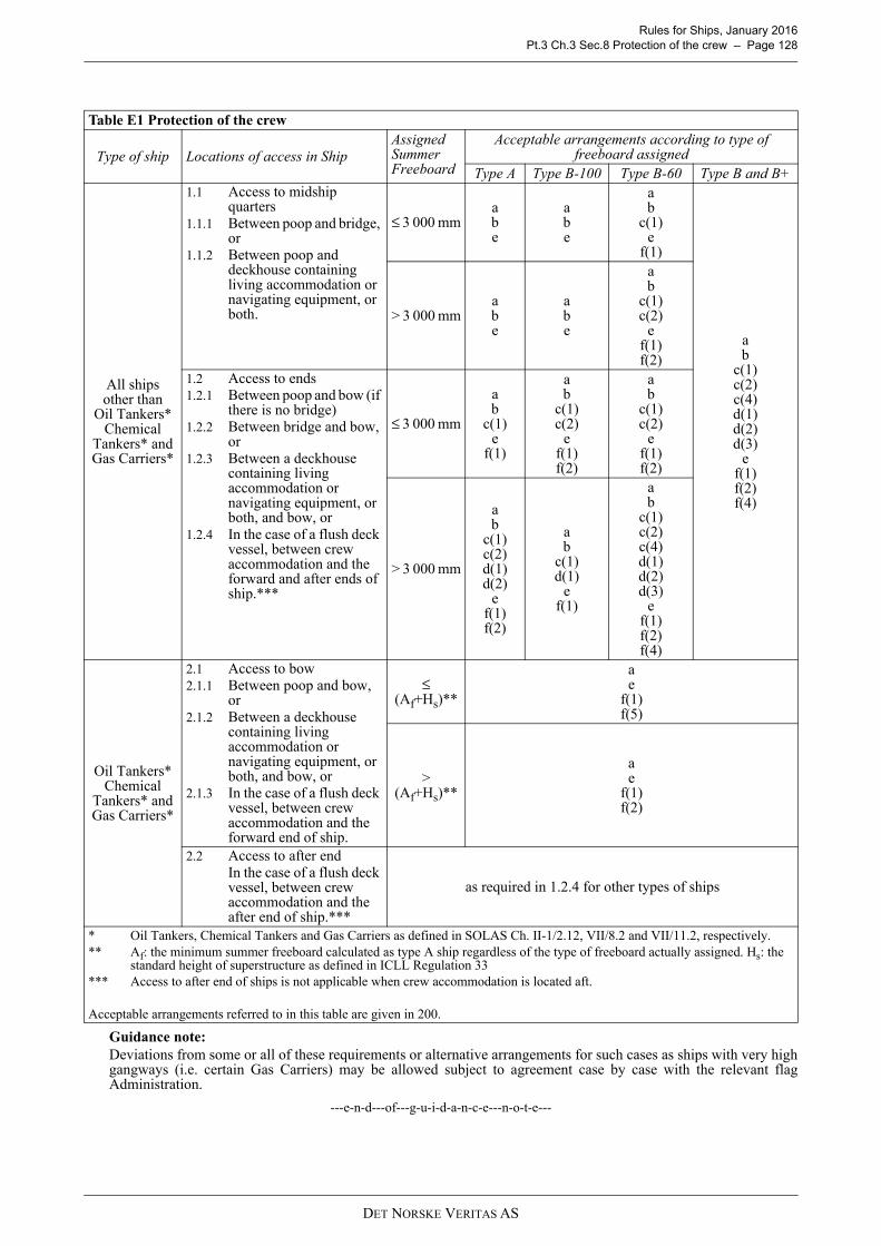
Rules for Ships, January 2016 Pt.3 Ch.3 Sec.8 Protection of the crew – Page 128
Guidance note:Deviations from some or all of these requirements or alternative arrangements for such cases as ships with very highgangways (i.e. certain Gas Carriers) may be allowed subject to agreement case by case with the relevant flagAdministration.
---e-n-d---of---g-u-i-d-a-n-c-e---n-o-t-e---
Table E1 Protection of the crew
Type of ship Locations of access in ShipAssigned Summer Freeboard
Acceptable arrangements according to type of freeboard assigned
Type A Type B-100 Type B-60 Type B and B+
All shipsother than
Oil Tankers*Chemical
Tankers* andGas Carriers*
1.1 Access to midship quarters
1.1.1 Between poop and bridge, or
1.1.2 Between poop and deckhouse containing living accommodation or navigating equipment, or both.
≤ 3 000 mmabe
abe
ab
c(1)e
f(1)
ab
c(1)c(2)c(4)d(1)d(2)d(3)
ef(1)f(2)f(4)
> 3 000 mmabe
abe
ab
c(1)c(2)
ef(1)f(2)
1.2 Access to ends1.2.1 Between poop and bow (if
there is no bridge)1.2.2 Between bridge and bow,
or1.2.3 Between a deckhouse
containing living accommodation or navigating equipment, or both, and bow, or
1.2.4 In the case of a flush deck vessel, between crew accommodation and the forward and after ends of ship.***
≤ 3 000 mm
ab
c(1)e
f(1)
ab
c(1)c(2)
ef(1)f(2)
ab
c(1)c(2)
ef(1)f(2)
> 3 000 mm
ab
c(1)c(2)d(1)d(2)
ef(1)f(2)
ab
c(1)d(1)
ef(1)
ab
c(1)c(2)c(4)d(1)d(2)d(3)
ef(1)f(2)f(4)
Oil Tankers*Chemical
Tankers* andGas Carriers*
2.1 Access to bow2.1.1 Between poop and bow,
or2.1.2 Between a deckhouse
containing living accommodation or navigating equipment, or both, and bow, or
2.1.3 In the case of a flush deck vessel, between crew accommodation and the forward end of ship.
≤ (Af+Hs)**
ae
f(1)f(5)
> (Af+Hs)**
ae
f(1)f(2)
2.2 Access to after endIn the case of a flush deck vessel, between crew accommodation and the after end of ship.***
as required in 1.2.4 for other types of ships
* Oil Tankers, Chemical Tankers and Gas Carriers as defined in SOLAS Ch. II-1/2.12, VII/8.2 and VII/11.2, respectively.** Af: the minimum summer freeboard calculated as type A ship regardless of the type of freeboard actually assigned. Hs: the
standard height of superstructure as defined in ICLL Regulation 33*** Access to after end of ships is not applicable when crew accommodation is located aft.
Acceptable arrangements referred to in this table are given in 200.
DET NORSKE VERITAS AS
Rules for Ships, January 2016 Pt.3 Ch.3 Sec.9 Stability – Page 129
SECTION 9 STABILITY
A. Application, definitions and document requirements
A 100 Application
101 All vessels with a length LF of 24 m and above shall comply with the stability requirements of thissection, as applicable for the main class.
102 The requirements in this section are in compliance with IMO 2008 Intact Stability Code (IMO Res.MSC.267(85)) and cover IACS UR L2.
103 For vessels with service restrictions as described in Pt.1 Ch.2 Sec.1 B400, modified stabilityrequirements may be considered if consistent with the applicable service restriction.
104 Vessels with a length LF of 24 m and above and with additional class notations shall comply withadditional stability requirements as given in the appropriate rule chapters.
105 Ships with loading computer systems intended for stability control shall comply with Pt.6 Ch.9 Sec.1 A200.
106 The stability for vessels for which lifting operations are the main or one of the main functions shall alsobe in compliance with the criteria given in Pt.5 Ch.7 Sec.17.The crane criteria shall be applied when the maximum heeling arm created by the crane and its load exceeds0.10 m at any operational displacement.
A 200 Terms
201 External watertight integrityThe capability of the hull structure and its external closing appliances to prevent downflooding to volumesassumed buoyant. The external watertight integrity includes position and type of closing appliances, alarms,indicators, remote controls and signboards fitted to such appliances.
202 WeathertightWeathertight means that in any sea conditions water will not penetrate into the ship.
203 WatertightCapable of preventing ingress of water during static submersion under a head of water for which thesurrounding structure is designed.A watertight closing appliance is also considered weathertight.
204 DownfloodingIngress of water through external openings to buoyancy volumes.
205 Downflooding angle related to intact stabilityThe minimum heel angle where an external opening without weathertight closing appliance is submerged.
206 LightweightLightweight is the displacement of a ship in tonnes without cargo, fuel, lubricating oil, ballast water, fresh waterand feed water in tanks, consumable stores, and passengers and crew and their effects.The lightweight definition stated in the Stability Manual indicates which items are included or not included inthe lightweight.
Guidance note:The approved lightweight data are the data which are approved for the purpose of stability approval and control butnot necessarily for determination of the deadweight.
---e-n-d---of---g-u-i-d-a-n-c-e---n-o-t-e---
207 Maximum allowable vertical centre of gravityThe maximum vertical centre of gravity of the vessel, corrected for free surface effect, which complies withthe stipulated stability requirements for the draught in question.
208 Preliminary stability documentationThe stability documentation which is based on estimated lightweight data.
209 Final stability documentationThe stability documentation which is based on approved lightweight data obtained from an inclining test orlightweight survey.
DET NORSKE VERITAS AS

Rules for Ships, January 2016 Pt.3 Ch.3 Sec.9 Stability – Page 130
A 300 Documentation requirements
301 Documentation shall be submitted as required by Table A1.
302 If the assignment of class shall be based on the approval of the Flag Administration according to Pt.1Ch.1 Sec.1 B500, a copy of the final stability documentation stamped by the Flag Administration and theapproval letter issued by the Flag Administration shall be submitted to the Society.
303 For general requirements to documentation, including definition of the Info codes see Pt.0 Ch.3 Sec.1and DNV Classification Note No. 20.1 “Stability Documentation”.
304 For a full definition of the documentation types, see Pt.0 Ch.3 Sec.2.
B. Surveys and tests
B 100 General
101 The following surveys and tests shall be carried out:
— external watertight integrity survey with respect to unprotected and protected openings together with theirclosing appliances, alarms, indicators and signboards, normally covered by the load line initial survey
— checking of draught marks— remote draught measurement and tank gauging systems— inclining test or lightweight survey.
C. General requirements
C 100 Stability book
101 An approved stability booklet shall be provided onboard. The stability booklet shall include informationas is necessary to enable the master by a rapid and simple process to obtain accurate guidance as to the stabilityof the ship under varying conditions of service.
Guidance note:The format and content of the stability book is further described in DNV Classification Note No. 20.1 and IACS UILL45.
---e-n-d---of---g-u-i-d-a-n-c-e---n-o-t-e---
102 Stability data and associated plans shall include a translation into English, if English is not used asofficial language.
C 200 Fixed ballast
201 If used, fixed ballast shall be installed in a manner that prevents shifting of position.
C 300 Draught marks
301 The ship shall have scale of draught marks at the bow and stern on both port and starboard side.Guidance note:The draught marks should reflect the extreme draught at the location where they are fitted. The stability manual shouldcontain guidance on, from draught mark readings, how to utilise the stability information contained therein.Norwegian Standard NS6301 may be referenced for further guidelines on the size and location of draught marks.
---e-n-d---of---g-u-i-d-a-n-c-e---n-o-t-e---
Table A1 Documentation requirementsObject Documentation type Additional description Info
Stability
B010 – Lines plan and offset tables FIB020 – External watertight integrity plan FIB050 – Preliminary stability manual APB100 – Inclining test and lightweight survey procedure
For each vessel.AP
B110 – Inclining test or lightweight survey report APB120 – Final stability manual AP
External watertight and weathertight integrity B200 – Freeboard plan FI
DET NORSKE VERITAS AS
Rules for Ships, January 2016 Pt.3 Ch.3 Sec.9 Stability – Page 131
C 400 Loading computer system
401 Loading computers for stability calculation shall be considered as supplementary to the approvedstability booklet.
402 Loading computers for stability control shall comply with Pt.6 Ch.9.
D. Intact stability criteria
D 100 General stability criteria
101 The following criteria are given for all ships:
— The area under the righting lever curve (GZ curve) shall not be less than 0.055 metre-radians up to θ = 30°angle of heel and not less than 0.09 metre-radians up to θ = 40° or the angle of flooding θ f if this angle isless than 40°. Additionally, the area under the righting lever curve between the angles of heel of 30° and40° or between 30° and θf, if this angle is less than 40°, shall not be less than 0.03 metre-radians.
— The righting lever (GZ) shall be at least 0.20 m at an angle of heel equal to or greater than 30°.— The maximum righting lever should occur at an angle of heel preferably exceeding 30° but not less than
25°.— The initial metacentric height, GM0 shall not be less than 0.15 m.
Guidance note:For ships carrying timber deck cargoes and provided that:
- the cargo extends longitudinally between superstructures end, or where there is no limiting superstructure at theafter end, the timber deck cargo shall extend at least to the after end of the aftermost hatchway
- the cargo extends transversely for the full beam of the ship after due allowance for a rounded gunwale notexceeding 4% of the breadth of the ship
- supporting uprights are secured and remain securely fixed at large angles of heelthe following criteria may be used instead of the criteria in 101:
- the area under the righting lever curve (GZ curve) should not be less than 0.08 metre-radians up to θ = 40° angleof heel or the angle of flooding θf if this angle is less than 40°
- the maximum value of the righting lever (GZ) should be at least 0.25 m- at all times during the voyage, the metacentric height GM0 should be positive after correction for the free surface
effects of liquid in tanks and, where appropriate, the absorption of water by the deck cargo and/or ice accretion onthe exposed surfaces. Additionally, in the departure condition, the metacentric height GM0 should not be less than0.10 m.
---e-n-d---of---g-u-i-d-a-n-c-e---n-o-t-e---
102 The following equivalent criteria are recommended where a vessel's characteristics render compliancewith 101 impracticable (based on IMO 2008 IS Code Part B Ch.2.4.5):
— The area under the curve of righting levers (GZ curve) should not be less than 0.070 metre-radians up to anangle of 15° when the maximum righting lever (GZ) occurs at 15° and 0.055 metre-radians up to an angleof 30° when the maximum righting lever (GZ) occurs at 30° or above. Where the maximum righting lever(GZ) occurs at angles of between 15° and 30°, the corresponding area under the righting lever curve shouldbe:
0.055 + 0.001 (30° − θmax) metre-radianswhere θmax is the angle of heel in degrees at which the righting lever curve reaches its maximum.
— The area under the righting lever curve (GZ curve) between the angles of heel of 30° and 40°, or between30° and θf this angle is less than 40°, should be not less than 0.03 metre-radians.
— The righting lever (GZ) should be at least 0.20 m at an angle of heel equal to or greater than 30°.— The maximum righting lever (GZ) should occur at an angle of heel not less than 15°.— The initial transverse metacentric height (GM0) should not be less than 0.15 m.
103 When anti-rolling devices are installed in a ship, the applicable intact stability criteria shall be satisfiedwhen the devices are in operation.
104 For certain ship types additional or alternative intact and damage stability criteria have been specified.
DET NORSKE VERITAS AS

Rules for Ships, January 2016 Pt.3 Ch.3 Sec.9 Stability – Page 132
These vessels (or class notations) are given in Table D1.
D 200 Weather criterion
201 For all ships with a length LF of 24 m and above, the criteria listed below shall be complied with (basedon IMO 2008 IS Code Part A Ch.2.3):1 The ability of a ship to withstand the combined effects of beam wind and rolling should be demonstrated foreach standard condition of loading, with reference to the Fig.1 as follows:1.1 - the ship is subjected to a steady wind pressure acting perpendicular to the ship's centreline which resultsin a steady wind heeling lever 1.2 - from the resultant angle of equilibrium (θ0), the ship is assumed to roll owing to wave action to an angleof roll (θ1) to windward. Attention should be paid to the effect of steady wind so that excessive resultant anglesof heel are avoided.The angle of heel under action of steady wind (θ0) should be limited to a certain angle to the satisfaction of theSociety. As a guide, 16° or 80% of the angle of deck edge immersion, whichever is less, is suggested.1.3 - the ship is then subjected to a gust wind pressure which results in a gust wind heeling lever 1.4 - under these circumstances, area “b” should be equal to or greater than area “a”;1.5 - free surface effects should be accounted for in the standard conditions of loading as set out in D301.
Table D1 Stability design requirements for different ship types and class notationsClass notation / Ship type Intact Damage Class Requirement IMO Reference1A1 X D101 IMO 2008 IS Code Part A Ch. 2.21A1, offshore/harbour service vessels
X D102 IMO 2008 IS Code Part B Ch. 2.4.5
1A1, wind X D201 IMO 2008 IS Code Part A Ch. 2.31A1, timber X D101 IMO 2008 IS Code Part A Ch. 3.3Tanker for Oil X Pt.5 Ch.3 Sec.3 A MARPOL 73/78 Reg. 27 Offshore service vessel X Pt.5 Ch.7 Sec.2 D IMO Res. MSC.235(82) Ch.2SF X
XPt.5 Ch.7 Sec.5 A102Pt.5 Ch.7 Sec.5 B
IMO Res. MSC.235(82) Ch.3
Tug X Pt.5 Ch.7 Sec.12 E No IMO requirementsFire Fighter I (or II or III) X Pt.5 Ch.7 Sec.7 I No IMO requirementsCRANE X Pt.6 Ch.1 Sec.3 E No IMO requirementsCrane Vessel X
X XPt.5 Ch.7 Sec.17 D200Pt.5 Ch.7 Sec.17 D100
No IMO requirements
DSV-SURFACE, -SAT) (diving support vessel)
X X Pt.5 Ch.16DNV-DSS-105DNV-OS-E402
IMO Res. MSC.235(82)
DEICE (de-icing/anti icing vessels)
X X Pt.6 Ch.1 Sec.4 B
Offshore vesselsWell Stimulation Vessel X X Pt.5 Ch.7 Sec.9 H IMO Res. MSC.235(82) Escort (n, V) X Pt.5 Ch.7 Sec.13 D No IMO requirementsStandby Vessel X X Pt.5 Ch.7 Sec.6 E No IMO requirementsOther vesselsPassenger Ship X Pt.5 Ch.2 Sec.2 F300 IMO 2008 IS Code Part A Ch.3.1 Car Ferry, Train Ferry or Car and Train Ferry
X Pt.5 Ch.2 Sec.3 F101 IMO 2008 IS Code Part A Ch.3.1
Fishing Vessel or Stern Trawler
X Pt.5 Ch.6 Sec.1 F To cover IMO 2008 IS Code Part B Ch.2.1Torremolinos International Conference Ch.III modified by the Torremolinos Protocol of 1993
Icebreaker/POLAR XX X
Pt.5 Ch.1 Sec.4 L300Pt.5 Ch.1 Sec.4 L100
IMO Res. A.1024(26)
Barge for Deck Cargo X Pt.5 Ch.7 Sec.14 I IMO 2008 IS Code Part B Ch.2.2SPS (<240 persons)SPS (240 persons or more)All SPS ships
XX
X
Pt.3 Ch.3 Sec.9 D100Pt.5 Ch.2 Sec.2 F300Pt.5 Ch.7 Sec.11 B200
IMO 2008 IS Code IMO 2008 IS Code IMO Res. MSC.266(84)
lw1( )
lw2( )
DET NORSKE VERITAS AS

Rules for Ships, January 2016 Pt.3 Ch.3 Sec.9 Stability – Page 133
Fig. 1Severe wind and rolling
The angles in Fig.1 are defined as follows:
θo = angle of heel under action of steady wind (see 1.2 and 3)θ1 = angle of roll to windward due to wave actionθ2 = angle of downflooding (θf) or 50° or θc whichever is less, where:θf = angle of heel at which openings in the hull, superstructures or deckhouses which cannot be closed
weathertight immerse. In applying this criterion, small openings through which progressive floodingcannot take place need not be considered as open.
θc = angle of second intercept between wind heeling lever and GZ curves.
2 The wind heeling levers and referred to in 1.1 and 1.3 are constant values at all angles ofinclination and should be calculated as follows:
P = 504 N/m2 (wind speed = 29 m/s). The value of P, used for ships in restricted service and/or for shipswith very large windage areas (due to coherence length for wind speed), may be reduced subject to theapproval of the Society
A = projected lateral area of the portion of the ship and deck cargo above the waterline (m2)Z = vertical distance from the centre of A to the centre of the underwater lateral area or approximately to a
point at one half the draught (m)disp = displacement (t)g = 9.81 m/s2
The angle of roll θ1 1) referred to in 1.2 should be calculated as follows:
1) The angle of roll for ships with anti-rolling devices should be determined without taking into account the operation of these devices.
X1 = factor as shown in Table D2X2 = factor as shown in Table D3k = 1.0 for round-bilged ship having no bilge or bar keels
= 0.7 for a ship having sharp bilges= as shown in Table D4 for a ship having bilge keels, a bar keel or both
r = 0.73 ± 0.6 OG/d, with: OG = distance between the centre of gravity and the waterline (m) (+ if centre of gravity is above the waterline,
- if it is below)
lw2( )
lw1( ) lw2
( )
lw1
PAZ1000 g disp------------------------------- (m) and=
lw21.5lw1
(m)=
θ1 109kX1X2 rs (degrees)=
DET NORSKE VERITAS AS

Rules for Ships, January 2016 Pt.3 Ch.3 Sec.9 Stability – Page 134
d = mean moulded draught of the ship (m)s = factor as shown in Table D5.
(Intermediate values in Tables D2 to D5 should be obtained by linear interpolation).Rolling period
C = 0.373 + 0.023 (B/d) - 0.043 (L/100)
The symbols in Tables D2 to D5 and the formula for the rolling period are defined as follows:
L = waterline length of the ship (m)B = moulded breadth of the ship (m)d = mean moulded draught of the ship (m)Cb = block coefficientAk = total overall area of bilge keels, or area of the lateral projection of the bar keel, or sum of these areas (m2)GM = metacentric height corrected for free surface effect (m).
Table D2 Values of factor X1
B/d X1≤ 2.42.52.62.72.82.93.03.13.23.33.4
≥ 3.5
1.00.980.960.950.930.910.900.880.860.840.820.80
Table D3 Values of factor X2
Cb X2≤ 0.450.500.550.600.65
≥ 0.70
0.750.820.890.950.971.0
Table D4 Values of factor k
k
01.01.52.02.53.03.5
≥ 4.0
1.050.980.950.880.790.740.720.70
Table D5 Values of factor sT s
< 678
12141618
≥ 20
0.1000.0980.0930.0650.0530.0440.0380.035
Ak100
LB----------------
T2 C B
GM-------------- (seconds)=
DET NORSKE VERITAS AS
Rules for Ships, January 2016 Pt.3 Ch.3 Sec.9 Stability – Page 135
202 Other calculation methods of equivalent safety level may be accepted as an alternative to the above.Guidance note:For some ships, the formulas may over-estimate the roll angle. As an alternative, the roll angle can be determined bymodel tests or direct calculations carried out for sea-states corresponding to the recommended wind speed.
---e-n-d---of---g-u-i-d-a-n-c-e---n-o-t-e---
D 300 Assumptions concerning intact stability criteria and calculations
301 For all loading conditions the initial metacentric height and the stability curves shall be corrected for theeffect of free surface of liquid in tanks.
Guidance note:The free surface should be taken into account as described in the IACS UI LL61.
---e-n-d---of---g-u-i-d-a-n-c-e---n-o-t-e---
302 Compliance with the stability criteria shall be checked for the main loading conditions intended by theowner in respect of the vessel's operation.
303 If the owner does not supply sufficiently detailed information regarding such loading conditions,calculations shall be made for the standard loading conditions in 304 and 305.
304 The following standard loading conditions apply to cargo ships:
— ship in the fully loaded departure condition, with cargo homogeneously distributed throughout all cargospaces and with full stores and fuel
— ship in the fully loaded arrival condition, with cargo homogeneously distributed throughout all cargospaces and with 10% stores and fuel remaining
— ship in ballast in departure condition, without cargo but with full stores and fuel— ship in ballast in arrival condition, without cargo and with 10% stores and fuel remaining.
305 The following additional loading conditions apply to cargo ships intended to carry deck cargoes:
— ship in the fully loaded departure condition with cargo homogeneously distributed in the holds and withcargo specified in extension and weight on deck, with full stores and fuel
— ship in the fully loaded arrival condition with cargo homogeneously distributed in the holds and with cargospecified in extension and weight on deck, with 10% stores and fuel.
306 In the fully loaded departure conditions in 304 and 305 the ship shall be assumed loaded to the summerload waterline, or if intended to carry timber deck cargo, to the summer timber load line. The water ballast tanksshould normally be assumed empty.
307 In all cases, the cargo in holds is assumed fully homogeneous unless this is inconsistent with the practicalservice of the ship.
308 Where timber deck cargoes are carried, the amount of cargo and ballast shall correspond to the worstservice condition in which all the stability criteria in D100 are met. In the arrival condition it shall be assumedthat the weight of the deck cargo has increased by 10% due to water absorption.
309 In all cases, when deck cargo is carried, a realistic stowage weight shall be assumed and stated, includingthe height of the cargo.
Guidance note:For ships carrying timber deck cargoes conditions should be shown indicating the maximum permissible amount ofdeck cargo having regard to the lightest stowage rate likely to be met in service.
---e-n-d---of---g-u-i-d-a-n-c-e---n-o-t-e---
310 Only those parts of the ship that are adequately protected by weathertight closing are accepted includedas buoyant in the stability calculations.
Guidance note:Reference is made to IMO Intact Code IMO 2008 IS Code Part B Ch.3.5 and the IACS UI LL62.
---e-n-d---of---g-u-i-d-a-n-c-e---n-o-t-e---
311 The Society may allow account to be taken in stability calculations of the buoyancy of the deck cargoassuming that such cargo has a permeability of 0.25.
DET NORSKE VERITAS AS

Rules for Ships, January 2016 Pt.3 Ch.3 Sec.9 Stability – Page 136
E. Damage stability
E 100 Damage stability
101 Vessels with additional class notations shall comply with the additional damage stability requirementsas given in the appropriate rule chapters.
102 When DNV is authorised to carry out stability approval on behalf of the Flag Administration,compliancewith the damage stability provisions required for issuance of the relevant international certificates shall bedemonstrated.
F. Determination of lightweight data
F 100 Application
101 Every passenger ship and cargo ship with length more than 24 metres shall be inclined upon itscompletion and the lightweight displacement and centre of gravity determined.
102 The inclining test required in 101 may be waived if basic stability data are available from the inclinationtest of a sister ship and it is shown that reliable stability information for the exempted ship can be obtained fromsuch basic data.
Guidance note 1:Dispensation according to 102 is not considered applicable to passenger ships and other ships where the lightweightis more than 75% of the total displacement.
---e-n-d---of---g-u-i-d-a-n-c-e---n-o-t-e---
Guidance note 2:The criteria for dispensation according to 102 are given in SOLAS Reg. II-1/5.2
---e-n-d---of---g-u-i-d-a-n-c-e---n-o-t-e---
F 200 Procedure
201 The inclining test shall be carried out in accordance with an approved test procedure or “Yard's checklistfor planning and execution of lightweight survey and inclining test” given in DNV Classification Note 20.1 -Appendix A. The inclining test shall be carried out in the presence of the Society's representative.
Guidance note:Guidelines for conducting inclining test or lightweight survey are given in IACS Rec. No. 31.
---e-n-d---of---g-u-i-d-a-n-c-e---n-o-t-e---
202 The inclining test report shall be signed by the person responsible for the test and by the Society'srepresentative.
203 The approved lightweight and centre of gravity shall be used in the final stability booklet.
F 300 Lightweight survey
301 A lightweight survey shall be carried out if an inclining test has been dispensed with according to 102.
DET NORSKE VERITAS AS
Rules for Ships, January 2016 Pt.3 Ch.3 CHANGES – HISTORIC – Page 137
CHANGES – HISTORIC
Note that historic changes older than the editions shown below have not been included. Older historic changes(if any) may be retrieved through http://www.dnvgl.com.
January 2015 edition
Main changes January 2015, entering into force July 2015
• Sec.5 Lifting appliances and foundations for heavy equipment, deck machinery and towing equipment
— C304: Reference aligned with IACS UR A2 Rev.3 Corr.1. ISO 13795 replaces ISO 3913 (which has beenwithdrawn).
• Sec.6 Openings and closing appliances
— H402 and I402: Design pressure has been reduced in accordance with IACS UR S27 Rev. 6.
July 2013 edition
Main changes coming into force 1 January 2014
• Sec.7 Corrosion Prevention
— A402: Text have been rephrased and the Guidance note has been deleted.— A403: New A403 regarding aluminumised pipes has been added.
July 2012 edition
Amendments January 2013
• Sec.2 Sternframes, Rudders and Steering
— An IACS reference was added to G405.
• Sec.3 Anchoring and Mooring Equipment
— Table G1 in G301 has been corrected.
• Sec.6 Openings and closing appliancesIn A General, the following amendments have been made:
— Table A1 has been reformatted to comply with the template for documentation requirements. Thedocumentation requirement given by K402 has been included in the table. The additional descriptionrelated to the freeboard plan has been deleted.
— Table A2 has been reformatted to comply with the template for certification requirements.
Main changes coming into force 1 July 2012
• Sec.1 General Requirements
— New subsection D “Materials” has been added.
• Sec.2 Sternframes, Rudders and Steering
— G405, correction in text.
• Sec.6 Openings and Closing Appliances
— L-Windows and Side Scuttles, has been completely revised and restructured to reflect the needs for a betterand more uniform use of the section.
Main changes coming into force 1 January 2013
• Sec.2 Sternframes, Rudders and Steering
— New text in B 400 “Certification”.
DET NORSKE VERITAS AS

Rules for Ships, January 2016 Pt.3 Ch.3 CHANGES – HISTORIC – Page 138
— In D101 Table D1, it is included coefficient for mixed rudder profiles e.g. HSVA rudders.— Fig.5 in E301 has been moved to E203 where it correctly belongs. — In G206, the factor β shall not be taken less than 0.25 when d/a is greater than 1.6.— In J104, updated the number in the figure reference to avoid misunderstanding about continuous slot
welding requirements.
• Sec.3 Anchoring and Mooring Equipment
— New text in A 200 Documentation requirements, A 300 Certification— In B101, text made more precise to avoid misunderstanding by also adding a guidance note.
• Sec.4 Masts and Rigging
— New text in A 400 Documentation requirements.
• Sec.5 Foundations for Deck Machinery, Towing Equipment and Lifting Appliances
— In A103, definition of working load has been introduced.— New text in A 200 Documentation requirements.— In A501, the whole text has been revised to make it more in line with the requirements Lifting Appliances
No.2.22.— In A503, in the Guidance Note the Supply Vessel notation has been replaced with the new correct
Offshore Service Vessel+ notation.— In B101, the text has been totally revised to also include requirements to heavy equipment.— In B102, there is included a reference to CN 8 “Conversions of Ships” for requirements to foundation
support of temporary deck mounted equipment.— In B201, the text has been amended.— In C104, the Supply Vessel notation has been replaced with the new correct Offshore Service Vessel+
notation.— New text in C200 Documentation requirements.— There has been added a guidance note in C401 with the intention to explain the requirements to towing.
• Sec.6 Openings and Closing Appliances
— In P200 Arrangement, the text in general has been amended in order to make it more precise and therebyavoid misunderstanding.
• Sec.9 Stability
— New text in A 300 Documentation requirements
DET NORSKE VERITAS AS