DNV OSS 301 Certification and Verification of Pipelines
58
OFFSHORE SERVICE SPECIFICATION DET NORSKE VERITAS DNV-OSS-301 CERTIFICATION AND VERIFICATION OF PIPELINES OCTOBER 2000
-
Upload
anis-kacem -
Category
Documents
-
view
64 -
download
3
description
DNV OSS 301 Certification and Verification of PipelinesOctober 2000
Transcript of DNV OSS 301 Certification and Verification of Pipelines
OFFSHORE SERVICE SPECIFICATION
DET NORSKE VERITAS
DNV-OSS-301
CERTIFICATION AND VERIFICATIONOF PIPELINES
OCTOBER 2000
Comments may be sent by e-mail to [email protected] subscription orders or information about subscription terms, please use [email protected] information about DNV services, research and publications can be found at http://www.dnv.com, or can be obtained from DNV, Veritas-veien 1, N-1322 Høvik, Norway; Tel +47 67 57 99 00, Fax +47 67 57 99 11.
© Det Norske Veritas. All rights reserved. No part of this publication may be reproduced or transmitted in any form or by any means, including pho-tocopying and recording, without the prior written consent of Det Norske Veritas.
Computer Typesetting (FM+SGML) by Det Norske Veritas.Printed in Norway by Det Norske Veritas October 2000.
If any person suffers loss or damage which is proved to have been caused by any negligent act or omission of Det Norske Veritas, then Det Norske Veritas shall pay compensation to such personfor his proved direct loss or damage. However, the compensation shall not exceed an amount equal to ten times the fee charged for the service in question, provided that the maximum compen-sation shall never exceed USD 2 million.In this provision "Det Norske Veritas" shall mean the Foundation Det Norske Veritas as well as all its subsidiaries, directors, officers, employees, agents and any other acting on behalf of DetNorske Veritas.
FOREWORD
DET NORSKE VERITAS (DNV) is an autonomous and independent foundation with the objectives of safeguarding life, prop-erty and the environment, at sea and onshore. DNV undertakes classification, certification, and other verification and consultancyservices relating to quality of ships, offshore units and installations, and onshore industries world-wide, and carries out researchin relation to these functions.
DNV Offshore publications consist of a three level hierarchy of documents:
— Offshore Service Specifications. Provide principles and procedures of DNV classification, certification, verification and con-sultancy services.
— Offshore Standards. Provide technical provisions and acceptance criteria for general use by the offshore industry as well asthe technical basis for DNV offshore services.
— Recommended Practices. Provide proven technology and sound engineering practice as well as guidance for the higher levelOffshore Service Specifications and Offshore Standards.
DNV Offshore publications are offered within the following areas:
A) Quality and Safety Methodology
B) Materials Technology
C) Structures
D) Systems
E) Special Facilities
F) Pipelines and Risers
G) Asset Operation
DET NORSKE VERITAS
Offshore Service Specification DNV-OSS-301, October 2000Contents – Page 3
CONTENTS
Sec. 1 General................................................................... 5
A. General....................................................................................5A 100 Introduction....................................................................... 5A 200 Objectives ......................................................................... 5A 300 Scope of application for certification................................ 5A 400 Scope of application for verification ................................ 5A 500 Structure of this document ................................................ 5A 600 Structure of pipeline-related documents ........................... 5
B. Background (Informative) ...................................................... 6B 100 Introduction....................................................................... 6B 200 Justifications for certification ........................................... 6
C. Certification ............................................................................6C 100 Certification to DNV-OS-F101 ........................................ 6C 200 Certification to other standards......................................... 6
D. Verification ............................................................................. 7D 100 General.............................................................................. 7
E. Definitions .............................................................................. 7E 100 General.............................................................................. 7E 200 Verbal forms ..................................................................... 7E 300 Definitions ........................................................................ 7
F. References .............................................................................. 8F 100 General.............................................................................. 8
Sec. 2 Principles of Risk-Differentiated Certificationand Verification ..................................................... 9
A. General....................................................................................9A 100 Objectives ......................................................................... 9
B. Verification Principles ............................................................ 9B 100 Purpose of verification...................................................... 9B 200 Verification as a complementary activity ......................... 9B 300 Verification management.................................................. 9B 400 Risk-Differentiated Levels of Certification and
Verification ....................................................................... 9
C. Selection of Level of Certification .......................................10C 100 Selection factors.............................................................. 10C 200 Overall safety objective ..................................................11C 300 Assessment of risk ..........................................................11C 400 Technical innovation and contractor experience ............ 11C 500 Quality management systems .........................................11
D. Information Flow.................................................................. 11D 100 Communication lines ...................................................... 11D 200 Obligations...................................................................... 11D 300 Notification of certification level....................................12
Sec. 3 Service Overview ................................................ 13
A. General..................................................................................13A 100 Objectives .......................................................................13
B. Service Process ..................................................................... 13B 100 General principles ........................................................... 13B 200 Scopes of work................................................................ 13
C. Pre-certification .................................................................... 13C 100 Verification during conceptual design ............................13
D. Certification ..........................................................................13D 100 General............................................................................ 13D 200 Verification of overall project management ...................13D 300 Verification during design ..............................................14D 400 Verification during construction..................................... 14
E. Certification Documents .......................................................15E 100 Purpose of certification documents.................................15E 200 Certification documents provided...................................16E 300 Validity of certification documents ................................ 16E 400 Certificate of Conformity................................................ 16
E 500 Statement of Compliance................................................ 17E 600 Verification reports ......................................................... 17E 700 Verification comments.................................................... 17E 800 Audit report..................................................................... 17E 900 Visit reports .................................................................... 17
F. Use of Quality Management Systems ..................................17F 100 General............................................................................ 17F 200 Quality plans................................................................... 18F 300 Inspection and test plans ................................................. 18F 400 Review of quality management programme................... 18
G. Maintenance of Pipeline Certificate .....................................18G 100 General............................................................................ 18G 200 Certificate of conformity with maintenance conditions . 18G 300 Validity of certification documents ................................ 18G 400 Maintaining the certificate .............................................. 18G 500 Verification during operation ........................................ 19G 600 Obligations...................................................................... 19G 700 Documentation hierarchy................................................ 20G 800 Non-conformance report................................................. 20
App. A Selection of Certification Level ......................... 21
A. General..................................................................................21A 100 General principles ........................................................... 21
B. Trigger Questions .................................................................21B 100 Overall safety objective .................................................. 21B 200 Assessment of risk .......................................................... 21B 300 Technical innovation ...................................................... 21B 400 Contractors’ experience .................................................. 21B 500 Quality management systems ......................................... 21
App. B List of Instances in DNV-OS-F101 whereAgreement or Acceptance is Necessary............. 22
A. General..................................................................................22A 100 Introduction..................................................................... 22
B. Design ...................................................................................22B 100 Instances of Acceptance or Agreement in DNV-OS-F101 -
Design ............................................................................. 22
C. Materials and Components ...................................................22C 100 Instances of Acceptance or Agreement in DNV-OS-F101 -
Materials and Components ............................................. 22
D. Installation (Including Welding and Non-destructiveTesting) .................................................................................23
D 100 Instances of Acceptance or Agreement in DNV-OS-F101 -Installation (Including Welding and Non-destructiveTesting) ........................................................................... 23
E. Operations.............................................................................24E 100 Instances of Acceptance or Agreement in DNV-OS-F101 -
Operations....................................................................... 24
App. C Generic Description of Project Sub-phases...... 25
A. General..................................................................................25A 100 Introduction..................................................................... 25
B. Initial Studies ........................................................................25B 100 Feasibility study.............................................................. 25B 200 Concept study ................................................................. 25
C. Design ...................................................................................25C 100 Basic design .................................................................... 25C 200 Detail design ................................................................... 25
D. Other Phases .........................................................................25D 100 General............................................................................ 25
App. D Examples of Certification Documents .............. 26
DET NORSKE VERITAS
Offshore Service Specification DNV-OSS-301, October 2000Page 4 – Contents
A. General..................................................................................26A 100 Introduction .....................................................................26A 200 Certificate of Conformity................................................27A 300 Statement of Compliance ................................................28A 400 Verification Comments Sheet .........................................29A 500 Audit Report....................................................................30A 600 Visit Report .....................................................................32
App. E Detailed Scope of work tables for Certificationand Verification................................................... 33
A. General..................................................................................33A 100 Introduction .....................................................................33
B. Description of Terms used in the Scope of Work Tables .....33B 100 General ............................................................................33B 200 Audit................................................................................33B 300 Surveillance.....................................................................33B 400 Hold Point .......................................................................33B 500 Review ............................................................................33
C. Overall Project Management ................................................33C 100 General ............................................................................33
C 200 Detailed scope of work for overall project management 34
D. Design ................................................................................... 34D 100 General ............................................................................34D 200 Design verification..........................................................34D 300 Low level design verification..........................................34D 400 Medium level design verification ...................................34D 500 High level design verification .........................................34D 600 Scope of work for design ................................................34
E. Construction.......................................................................... 38E 100 General ............................................................................38E 200 Construction verification.................................................38E 300 Low level construction verification ................................39E 400 Medium level construction verification ..........................39E 500 High level construction verification................................39E 600 Verification of work in progress .....................................39E 700 DNV final report .............................................................39E 800 Detailed scope of work for construction .........................39
F. Operations.............................................................................58F 100 General ............................................................................58
DET NORSKE VERITAS
Offshore Service Specification DNV-OSS-301, October 2000Sec.1 – Page 5
SECTION 1GENERAL
A. General
A 100 Introduction
101 This Offshore Service Specification (OSS) gives criteriafor and guidance on certification of complete pipeline systemsand verification of the integrity of parts or phases of pipelinesystems.
A 200 Objectives
201 The objectives of this document are to:
— describe DNV’s certification and verification services forpipeline systems
— provide guidance for owners and other parties for the se-lection of the level of involvement of those carrying outthe certification and verification activities
— provide a common communication platform for describ-ing extent of verification activities.
A 300 Scope of application for certification
301 This Offshore Service Specification applies to certifica-tion and verification during the design, construction and oper-ation of pipeline systems.
302 This OSS describes the necessary activities to be carriedout to obtain an initial DNV pipeline system certificate of con-formity and how to maintain this certificate.
303 Statutory certification of pipeline systems to the require-ments of National Authorities is not included specifically inthe scope of application of this OSS. Such certification shall begoverned by the regulations of the appointing authority. How-ever, if detailed procedures are not given by these authorities,this OSS will be used by DNV as a guideline for its work.
304 The primary scope of the certification work is the verifi-cation of the integrity of the pipeline, or its capacity to containthe contents under the specified conditions. Other aspects,such as the verification of the environmental impact of thepipeline system, or its fitness for purpose with respect to flowcapacity and flow assurance, may be included in DNV’s scopeof work, if desired by the client.
A 400 Scope of application for verification
401 This OSS may be adopted for the verification of parts ofa pipeline system or selected project phases.
402 This OSS describes the principle of a levelled verifica-tion involvement, which easily can be used in communicationsabout the extent and scope of verification activities that are notpart of a scheme for pipeline certification.
403 This principle applies both to internal company verifica-tion (second party) as well as any obligations of licensees’ forexternal verification (third party) in waters where this is appli-cable.
404 Guidance note:The essential difference between the terms Certification and Ver-ification is that Certification is used only where DNV’s scopecovers the integrity of the entire pipeline system and results in theissue of a DNV pipeline certificate
While Verification is used where DNV’s scope applies to the ver-ification of only a single (or more) phase of the project, for ex-ample, verification of the design but not of construction,installation or testing. Verification results in the issue of a DNVstatement of compliance.
---e-n-d---of---G-u-i-d-a-n-c-e---n-o-t-e---
A 500 Structure of this document
501 This document consist of three sections and five appen-dices:
Section 1 gives the general scope of the document, in-formative background information, definitionsand references.
Section 2 explains the principles of DNV pipeline systemcertification with its risk-differentiated levels ofinvolvement, and how to define the level of in-volvement for a particular project.
Section 3 describes the certification process and the activ-ities for each of the project phases. Furthermore,it describes the documents issued during and asa result of the certification process. The use ofquality management systems is addressed herealso.
Appendix A poses trigger questions for the selection of certi-fication or verification level.
Appendix B lists the instances where DNV-OS-F101 re-quires acceptance or agreement.
Appendix C contains generic descriptions of project sub-phases.
Appendix D gives example certification documents.Appendix E gives detailed scope of work tables for all phases
and all level of involvement. These tables are thebasis for the development of project specificscope of work tables.
A 600 Structure of pipeline-related documents
601 Reference is made to the foreword of this DNV-OSS.From the structure described there, documents relating to pipe-line systems consist of a three-level hierarchy with these mainfeatures:
— Principles and procedures related to DNV’s certificationand verification services are separate from technical re-quirements and are presented in DNV Offshore ServiceSpecifications.
— Technical requirements are issued as self-contained DNVOffshore Standards.
— Associated product documents are issued as DNV Recom-mended Practices.
Guidance note:Product documents issued under previous document structuresmay be called “Classification Notes” or “Guidelines”.
---e-n-d---of---G-u-i-d-a-n-c-e---n-o-t-e---
602 This hierarchy is designed with these objectives:
— Offshore Service Specifications present the scope and ex-tent of DNV’s services.
— Offshore Standards are issued as neutral technical stand-ards to enable their use by national authorities, as interna-tional codes and as company or project specificationswithout reference to DNV’s services.
— The Recommended Practices give DNV’s interpretationof safe engineering practice for general use by industry.
Guidance note:The latest revision of all DNV documents may be found in thepublications list in the DNV web site www.dnv.com.
---e-n-d---of---G-u-i-d-a-n-c-e---n-o-t-e---
DET NORSKE VERITAS
Offshore Service Specification DNV-OSS-301, October 2000Page 6 – Sec.1
B. Background (Informative)
B 100 Introduction
101 Certification of pipelines has been carried out historical-ly with a variety of scope and depth of involvement by the cer-tifying body, but with the same end result – a certificate. Thedepth of involvement, or level of certification, has not alwaysbeen easily detected from the certificate.
102 This document outlines different levels of certificationinvolvement to be selected by the owner, which will ensurethat the certifier’s scope is well defined. Further, by stating thislevel on the certificate, the recipients of the certificate also willbe informed of the scope.
Guidance note:The purpose of the pipeline system certificate is to confirm thatthe pipeline, as installed and ready for use, is in a condition thatcomplies with the technical requirements. It does not confirmthat the schedule or cost of the project has been according to plan.Strictly, the certificate covers only the as-installed condition ofthe pipeline and, hence, the conditions affecting this are of par-ticular interest. However, the certification process requires thatall the prior phases are verified and that temporary phases are inaccordance with DNV-OS-F101 and have an acceptable risk lev-el.Further, the certification or verification can be a fully re-activeprocess. This means that only the ‘final steps’ are verified, with-out regard to the consequences of e.g. detection of non-compli-ances or flaws late in the design or production processes. ‘Finalstep’ means the final step in which a mistake or flaw affecting thepipeline system as installed, can be detected and rectified.A more supportive certification or verification is achieved whenthe verification process is pro-active. Then the certifier takes anactive part in contributing to the achievement of the projectschedule, budget and optimum quality. Typically, this will beachieved through an early involvement and active feedback intothe project based on DNV's extensive pipeline experience. Suchearly involvement in the design or construction processes mayhelp to ensure that no surprises are encountered at such a latestage that it will seriously affect the cost and / or schedule of theproject.The certification or verification will, in both of the described sce-narios, provide a Statement of Compliance at the completion ofeach of the project’s stages. A Certificate of Conformity will beprovided when the pipeline is ready for operation only whenDNV’s scope of work is the certification of the complete pipelineproject.
---e-n-d---of---G-u-i-d-a-n-c-e---n-o-t-e---
B 200 Justifications for certification
201 Some national authorities require certification of pipe-line systems and have appointed specific organisations quali-fied for this work.
202 Some of these national authorities may have detailed re-quirements to the certification activity, while others leave thedefinition of the necessary work up to the appointed organisa-tion. Other national authorities require specific documents tobe verified and approved by them, some hold the Owner re-sponsible for the verification activities and others again maynot have any specific requirements.
Guidance note:The term statutory certification is sometimes used to distinguishcertification performed by appointment of a national authorityfrom that performed on the general recognition of the certifier.
---e-n-d---of---G-u-i-d-a-n-c-e---n-o-t-e---
203 However, even where national authorities do not requirecertification of pipeline systems, certification is a convenienttool for the owner to get an independent verification of his con-tractor(s) work or to show financiers, partners, insurers and thepublic that the pipeline system complies with the relevantstandard.
204 Certification of pipeline systems has the benefit of pro-viding the owner (and other interested parties) confidence thatthe:
— pipeline system has sufficient integrity to fulfil its speci-fied purpose
— risks to personnel associated with the pipeline system arereduced as low as reasonably practicable.
205 Additionally, it is good business practice to subject crit-ical work to a third-party check as this minimises the possibil-ity of errors remaining undetected. Third-party certificationwill ensure that the verifier has an independent view and per-spective when performing this activity. Furthermore, it willavoid the situation where errors could be overlooked by engi-neers because of their closeness to the work with the pipelinesystem.
206 Certification also can be used as a part of the project riskmanagement. The failure of pipeline systems may expose theowner to:
— safety risks— environmental risks— economic risks— political risks.
207 As certification increases confidence that the pipelinecomplies with the requirements placed on it by national author-ities and the owner, it follows that the risk of failure of thepipeline decreases due to independent certification. Thus, cer-tification contributes to project risk management and reduc-tion.
C. Certification
C 100 Certification to DNV-OS-F101
101 The certification process described in this OSS is tailor-made for pipeline systems in accordance with DNV-OS-F101.
102 Wherever DNV-OS-F101 refers to acceptance, agree-ment and qualification this shall be by DNV. A list of these in-stances is provided in Appendix B.
C 200 Certification to other standards
201 DNV certification to internationally recognised stand-ards other than DNV-OS-F101 shall follow the principles de-scribed in this OSS.
202 Where combinations of standards and external criteriaare used the exact terms of reference and documents to be is-sued shall be agreed at the beginning of the project and formal-ly defined in the contract.
203 The use of other standards does not allow for a reductionof the quality management requirements as described in thesafety philosophy of DNV-OS-F101.
204 DNV reserves the right to call for additional require-ments to cover issues essential to the certification process andnot covered by the standards in question.
205 It is recommended strongly not to mix standards due tothe possible differences in safety philosophies.
Guidance note:Most standards are a coherent collection of requirements for allthe relevant aspects of a pipeline system. These aspects, e.g. loadand resistance, are normally among themselves adjusted to givean overall acceptable safety level. To pick requirements from dif-ferent standards can then easily result in unpredictable (low) lev-els of safety.
---e-n-d---of---G-u-i-d-a-n-c-e---n-o-t-e---
DET NORSKE VERITAS
Offshore Service Specification DNV-OSS-301, October 2000Sec.1 – Page 7
D. Verification
D 100 General
101 This OSS describes the principles of verification of thepipeline system for all phases.
102 Applying these principles of verification for distinctsmaller or larger parts of the pipeline system or selected phasesdoes not result in a certificate. Therefore, instead of the namecertification, the term verification is used to describe this serv-ice.
103 Verification to DNV-OS-F101, other standards or cli-ents’ specifications may use this OSS as a communication plat-form and for the preparation of project-specific scope of worktables in the same manner as for certification.
E. Definitions
E 100 General
101 The definitions in DNV-OS-F101 section 1 C200 alsoapply to this OSS.
102 The most important definitions from DNV-OS-F101 ap-plied in this OSS are repeated. They are marked “(DNV-OS-F101)” between the word and its definition, ref. e.g. verifica-tion.
E 200 Verbal forms
201 The terms will, can and may are used when describingDNV’s actions or activities, and the terms shall, should andmay are used when referring to other parties than DNV.
202 Shall: Indicates requirements strictly to be followed inorder to conform to this OSS and from which no deviation ispermitted.
203 Should: Indicates that among several possibilities, one isrecommended as particularly suitable, without mentioning orexcluding others, or that a certain course of action is preferredbut not necessarily required. Other possibilities may be appliedsubject to agreement.
204 Will: Indicates a mandatory action or activity to be un-dertaken by DNV. (Ref. “shall” for other parties.)
205 Can: Indicates an action or activity that DNV not neces-sarily does unless specifically requested by the client. (Ref.“should” for other parties.)
206 May: Verbal form used to indicate a course of actionpermissible within the limits of the OSS.
E 300 Definitions
301 Certificate of Conformity: A document signed by a qual-ified party affirming that, at the time of assessment, the productor service met the stated requirements (BS 4778: Part 2).
Guidance note:For this OSS, the document is a DNV Submarine Pipeline Sys-tem Certificate of Conformity and it is signed by DNV.
This OSS allows, under special agreement, the DNV SubmarinePipeline System Certificate of Conformity to be issued with a va-lidity period past the date of issue.
For this OSS, a Certificate is a short document (often a singlepage) stating compliance with specified requirements. The re-sults from associated verification shall be contained in a separate(single or multiple volume) report.
---e-n-d---of---G-u-i-d-a-n-c-e---n-o-t-e---
302 Certification: Used in this document to mean all the ac-tivities associated with process leading up to the Certificate.
Guidance note:In this OSS when Certification is used it designates the overallscope of work or multiple activities for the issue of a Certificate,whilst Verification is also used for single activities associatedwith the work. This in essence means that Certification is Verifi-cation for which the deliverable includes the issue of a Certifi-cate.
Other (related) definitions are:
BS 4778 Part 2. Certification: The authoritative act of document-ing compliance with requirements.
EN 45011. Certification of Conformity: Action by a third party,demonstrating that adequate confidence is provided that a dulyidentified product, process or service is in conformity with a spe-cific standard or other normative document
ISO 8402 1994. Verification: Confirmation by examination andprovision of objective evidence that specified requirements havebeen fulfilled.
---e-n-d---of---G-u-i-d-a-n-c-e---n-o-t-e---
303 Client: DNV’s contractual partner. It may be the pur-chaser, the owner or the contractor.
304 Construction phase (DNV-OS-F101): All phases duringconstruction, including fabrication, installation, testing andcommissioning, up until the installation or system is safe andoperable for intended use. In relation to pipelines, this includestransportation, on-shore and on-barge welding, laying, rectifi-cation, tie-in, pressure testing, commissioning and repair.
305 Design (DNV-OS-F101): All related engineering to de-sign the pipeline including both structural as well as materialand corrosion.
306 Design phase: An initial pipeline phase that takes a sys-tematic approach to the production of specifications, drawingsand other documents to ensure that the pipeline meets specifiedrequirements (including design reviews to ensure that designoutput is verified against design input requirements).
307 DNV Submarine Pipeline System Certificate of Con-formity: see A.101. The term ‘the pipeline certificate’ is usedin the text of this OSS.
308 Fabrication (DNV-OS-F101): Activities related to theassembly of objects with a defined purpose. In relation to pipe-lines, fabrication refers to e.g. risers, expansion loops, bundles,reels, etc.
309 Hazard: A deviation (departure from the design and op-erating intention) which could cause damage, injury or otherform of loss (Chemical Industries Association HAZOPGuide).
310 HAZOP (HAZard and OPerability study): The applica-tion of a formal systematic critical examination to the processand engineering intentions of new or existing facilities to as-sess the hazard potential of mal-operation or mal-function ofindividual items of equipment and their consequential effectson the facility as a whole (Chemical Industries AssociationHAZOP Guide).
311 Installation (activity) (DNV-OS-F101): The operationsrelated to installing the equipment, pipeline or structure, e.g.pipeline laying, tie-in, piling of structure etc., including finaltesting and preparation for operation.
312 Manufacture (DNV-OS-F101): Making of articles ormaterials, often in large volumes. In relation to pipelines, re-fers to activities for the production of linepipe, anodes and oth-er components and application of coating, performed undercontracts from one or more Contractors
313 Operations (phase): The phase when the pipeline is be-ing used for the purpose for which it was designed.
314 Risk (DNV-OS-F101): The qualitative or quantitativelikelihood of an accident or unplanned event occurring, con-sidered in conjunction with the potential consequences of such
DET NORSKE VERITAS
Offshore Service Specification DNV-OSS-301, October 2000Page 8 – Sec.1
a failure. In quantitative terms, risk is the quantified probabil-ity of a defined failure mode times its quantified consequence.
315 Risk Reduction Measures: Those measures taken to re-duce the risks to the operation of the pipeline system and to thehealth and safety of personnel associated with it or in its vicin-ity by:
— reduction in the probability of failure— mitigation of the consequences of failure.
Guidance note:The usual order of preference of risk reduction measures is:
1) Inherent safety
2) Prevention
3) Detection
4) Control
5) Mitigation
6) Emergency response.
---e-n-d---of---G-u-i-d-a-n-c-e---n-o-t-e---
316 Safety Objectives: The safety goals for the construction,operation and decommissioning of the pipeline including ac-ceptance criteria for the level of risk acceptable to the owner.
317 Statement of Compliance: A statement or report signedby a qualified party affirming that, at the time of assessment,the defined pipeline phase, or collection of activities, met therequirements stated by the owner.
318 Verification (DNV-OS-F101): An examination to con-firm that an activity, a product or a service is in accordancewith specified requirements.
Guidance note:The examination shall be based on information, which can beproved true, based on facts obtained through observation, meas-urement, test or other means.See also Certification.
---e-n-d---of---G-u-i-d-a-n-c-e---n-o-t-e---
F. References
F 100 General101 Offshore Standard DNV-OS F-101 Submarine PipelineSystems, 2000, Det Norske Veritas, Høvik.
102 A Guide to Hazard and Operability Studies, 1979,Chemical Industries Association Limited, London.
103 ISO 8402 Quality – Vocabulary, 1994, International Or-ganization for Standardization, Geneva.
104 BS 4778 Quality Vocabulary, Part 2 Quality Conceptsand Related Definitions, 1991, British Standards Institute,London.
105 En 45011 General Criteria for Certification Bodies Op-erating Product Certification, 1998, European Committee forStandardization, Brussels
DET NORSKE VERITAS
Offshore Service Specification DNV-OSS-301, October 2000Sec.2 – Page 9
SECTION 2PRINCIPLES OF RISK-DIFFERENTIATED
CERTIFICATION AND VERIFICATION
A. General
A 100 Objectives
101 The objectives of this section are to provide:
— introduction to the principles of certification and verifica-tion of pipeline systems
— introduction to the principles of risk differentiated levelsof verification activity
— guidance on the selection of levels of certification and ver-ification.
B. Verification Principles
B 100 Purpose of verification
101 Verification constitutes a systematic and independentexamination of the various phases in the life of a pipeline sys-tem to determine whether it has (or continues to have) suffi-cient integrity for its purpose.
102 Verification activities are expected to identify errors orfailures in the work associated with the pipeline system and tocontribute to reducing the risks to the operation of the pipelinesystem and to the health and safety of personnel associatedwith it or in its vicinity.
103 Verification is primarily focused on integrity and (hu-man) safety, but business risk (cost and schedule) may be ad-dressed also.
B 200 Verification as a complementary activity
201 Verification shall be complementary to routine design,construction and operations activities and not a substitute forthem. Therefore, although verification will take into accountthe work, and the assurance of that work, carried out by the oowner and its contractors, it is inevitable that certification willduplicate some work that has been carried out previously byother parties involved in the pipeline system.
202 Verification shall be developed and implemented insuch a way as to minimise additional work, and cost, but tomaximise its effectiveness. This development of verificationshall depend on the findings from the examination of qualitymanagement systems, the examination of documents and theexamination of production activities.
B 300 Verification management
301 The certification philosophy and verification methodsused will be described to ensure satisfactory completion of cer-tification and verification.
302 The philosophy and these methods will ensure that cer-tification and verification:
— have a consistent and constructive approach to the satis-factory completion and operation of the pipeline system
— are available world-wide wherever the owner or his con-tractors operate
— use up-to-date methods, tools and procedures— use qualified and experienced personnel.
303 All certification and verification activities will be car-ried out by competent personnel. Competence includes havingthe necessary theoretical and practical knowledge and experi-ence of the activity being examined. An adequate verification
of some activities may require access to specialised technicalknowledge.
304 As well as demonstrating competence of individuals, theverification organisation also will be able to show competenceand experience in pipeline verification and certification work.
B 400 Risk-Differentiated Levels of Certification andVerification401 To achieve a DNV Certificate of Conformity for a pipe-line system a verification of the activities described by thescope of work defined within this OSS shall first take place.
402 The level of verification activity is differentiated accord-ing to the risk to the pipeline. If the risk to the pipeline is high-er, the level of verification involvement is higher. Conversely,if the risk to the pipeline is lower, the level of verification ac-tivities can be reduced, without any reduction in their effec-tiveness.
403 It is emphasised that the activity level describes thedepth of the verification involvement and not different certifi-cate levels. It follows, therefore, that an increase in the level ofinvolvement above that considered necessary, based on anevaluation of the risks, involves minimal extra risk reductionfor increased cost. This practice is unlikely to be cost-effective.
404 Certification of pipeline systems is categorised into low,medium and high. A summary of the levels of involvement isgiven in Table 2-1.
Medium is the customary level of certification activity and isapplied to the majority of pipelines.
High is the level of certification applied where the risks tothe pipeline are higher because, for example, it hashighly corrosive contents, it is in adverse environ-mental conditions, it is technically innovative or thecontractors are not well experienced in the designand construction of similar pipelines.
Low is the level of certification applied where the risks tothe pipeline are lower because, for example, it hasbenign contents, it is located in congenial environ-mental conditions, or the contractors are well expe-rienced in the design and construction of similarpipelines.
405 It is the prerogative of the owner of the pipeline systemto choose the level of certification. The selection should con-sider the factors given in Sec.2 B. The selection of the mostsuitable certification level may be guided by using the ques-tions proposed in Appendix A.
406 As DNV is issuing the pipeline certificate, DNV will usethe same type of questions to evaluate the suitability of the se-lected level.
407 Different levels of certification can be chosen for differ-ent phases of the pipeline system, or even within the samephase if necessary. For example, pipeline design may be inno-vative and considered high risk whereas the installation meth-od is well known and considered low risk. The converse mightbe true also.
Additionally, linepipe production from a well known mill maybe considered low risk, whereas, production from an unknownmill may be considered high risk.
408 The level of certification can be reduced or increasedduring a phase if the originally chosen level is considered toorigorous or too lenient, as new information on the risks to thepipeline system becomes available.
DET NORSKE VERITAS
Offshore Service Specification DNV-OSS-301, October 2000Page 10 – Sec.2
409 Certification should be planned in close co-operationwith the owner and each of its contractors, to provide a scopeof work that is tailor-made to the schedule of each productionprocess/activity, i.e. to make the verification activities, surveil-lance and hold points, an integrated activity and not a delayingactivity.
Guidance note:
Many Contractors have adequate quality control systems andquality control departments, with competent personnel to per-form, for example, inspection at mills and coating plants and spe-cialist material engineers competent to review and verify theperformance of mills.
In that case, all certification work need not be done by DNV per-sonnel. Where applicable, the various inspections may be carriedout by competent persons other than DNV personnel.
In that situation DNV’s certification activities can be confined to:
- reviewing the competence of the contractor’s personnel- auditing their working methods and their performance of that
work- reviewing the documents produced by them.
---e-n-d---of---G-u-i-d-a-n-c-e---n-o-t-e---
410 Certification will direct greatest effort at those elementsof the pipeline system whose failure or reduced performance
will have the most significant impact on safety as well asproject risk.
411 The degree of confidence placed in a certificate by its us-ers depends on their degree of confidence in the certificationcarried out. Therefore, the level of certification will be statedon the pipeline certificate.
412 If more than one certification level has been used for aphase, then the lowest level will be reported on the state-ment(s) and the pipeline certificate, and the additional verifica-tion activities will be identified and described in theverification report(s).
C. Selection of Level of Certification
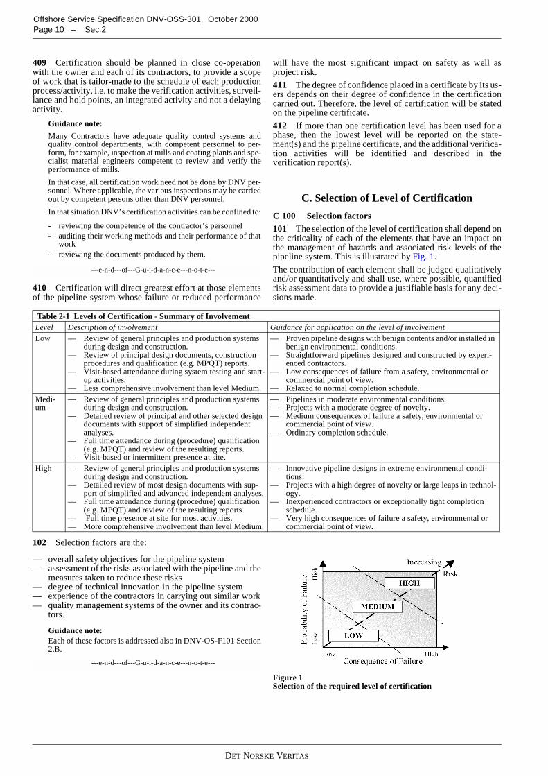
C 100 Selection factors101 The selection of the level of certification shall depend onthe criticality of each of the elements that have an impact onthe management of hazards and associated risk levels of thepipeline system. This is illustrated by Fig. 1.
The contribution of each element shall be judged qualitativelyand/or quantitatively and shall use, where possible, quantifiedrisk assessment data to provide a justifiable basis for any deci-sions made.
102 Selection factors are the:
— overall safety objectives for the pipeline system— assessment of the risks associated with the pipeline and the
measures taken to reduce these risks— degree of technical innovation in the pipeline system— experience of the contractors in carrying out similar work— quality management systems of the owner and its contrac-
tors.
Guidance note:Each of these factors is addressed also in DNV-OS-F101 Section2.B.
---e-n-d---of---G-u-i-d-a-n-c-e---n-o-t-e---
Figure 1Selection of the required level of certification
Table 2-1 Levels of Certification - Summary of InvolvementLevel Description of involvement Guidance for application on the level of involvementLow — Review of general principles and production systems
during design and construction.— Review of principal design documents, construction
procedures and qualification (e.g. MPQT) reports.— Visit-based attendance during system testing and start-
up activities.— Less comprehensive involvement than level Medium.
— Proven pipeline designs with benign contents and/or installed inbenign environmental conditions.
— Straightforward pipelines designed and constructed by experi-enced contractors.
— Low consequences of failure from a safety, environmental orcommercial point of view.
— Relaxed to normal completion schedule.Medi-um
— Review of general principles and production systemsduring design and construction.
— Detailed review of principal and other selected designdocuments with support of simplified independentanalyses.
— Full time attendance during (procedure) qualification(e.g. MPQT) and review of the resulting reports.
— Visit-based or intermittent presence at site.
— Pipelines in moderate environmental conditions.— Projects with a moderate degree of novelty.— Medium consequences of failure a safety, environmental or
commercial point of view.— Ordinary completion schedule.
High — Review of general principles and production systemsduring design and construction.
— Detailed review of most design documents with sup-port of simplified and advanced independent analyses.
— Full time attendance during (procedure) qualification(e.g. MPQT) and review of the resulting reports.
— Full time presence at site for most activities.— More comprehensive involvement than level Medium.
— Innovative pipeline designs in extreme environmental condi-tions.
— Projects with a high degree of novelty or large leaps in technol-ogy.
— Inexperienced contractors or exceptionally tight completionschedule.
— Very high consequences of failure a safety, environmental orcommercial point of view.

DET NORSKE VERITAS
Offshore Service Specification DNV-OSS-301, October 2000Sec.2 – Page 11
C 200 Overall safety objective
201 An overall safety objective covering all phases of thepipeline system from design to operation should be defined bythe owner. The safety objective should address the main safetygoals as well as establishing acceptance criteria for the level ofrisk acceptable to the owner. Depending on the pipeline and itslocation the risk could be measured in terms of human injuriesas well as environmental, political and economic consequenc-es.
C 300 Assessment of risk
301 A systematic review should be carried out to identifyand evaluate the probabilities and consequences of failures inthe pipeline system. The extent of the review shall reflect thecriticality of the pipeline system, the planned operation andprevious experience with similar pipeline systems. This reviewshall identify the risk to the operation of the pipeline systemand to the health and safety of personnel associated with it orin its vicinity.
302 Once the risks have been identified their extent can bereduced to a level as low as reasonably practicable by means ofone or both of:
— reduction in the probability of failure— mitigation of the consequences of failure.
Guidance note:Reasonable practicability
The term “as low as reasonably practicable (ALARP)” has comeinto use through the United Kingdom’s “The Health and Safetyat Work etc. Act 1974”. Reasonable Practicability is not definedin the Act but has acquired meaning by interpretations in thecourts.
It has been interpreted to mean that the degree of risk from anyparticular activity can be balanced against the cost, time and trou-ble of the measures to be taken to reduce the risk.
It follows, therefore, that the greater the risk the more reasonableit would be to incur substantial cost, time and effort in reducingthat risk. Similarly, if the risk was very small it would not be rea-sonable to expect great expense or effort to be incurred in reduc-ing it.
---e-n-d---of---G-u-i-d-a-n-c-e---n-o-t-e---
303 The result of the systematic review of these risks ismeasured against the safety objectives and used in the selec-tion of the appropriate certification activity level.
C 400 Technical innovation and contractor experience
401 The degree of technical innovation in the pipeline sys-tem shall be considered. Risks to the pipeline are likely to begreater for a pipeline with a high degree of technical innova-tion than with a pipeline designed, manufactured and installedto well-known criteria in well-known waters.
402 Similarly, the degree of risk to the pipeline systemshould be considered where contractors are inexperienced orthe work schedule is tight.
403 Factors to be considered in the selection of the appropri-ate certification level include:
— degree of difficulty in achieving technical requirements— knowledge of similar pipelines— knowledge of contractors’ general pipeline experience— knowledge of contractors’ experience in similar work.
C 500 Quality management systems
501 Adequate quality management systems shall be imple-mented to ensure that gross errors in the work for pipeline sys-tem design, construction and operations are limited.
502 Factors to be considered when evaluating the adequacyof the quality management system include:
— whether or not an ISO 9000 or equivalent certified systemis in place
— results from external audits— results from internal audits— experience with contractors’ previous work— project work-force familiarity with the quality manage-
ment system, e.g. has there been a rapid expansion of thework force or are all parties of a joint venture familiar withthe same system.
Guidance note:Most organisations have quality management systems certifiedby an accredited third party certification body. However, whenbusiness increases, they expand their staff quickly by taking oncontract personnel often for a fixed period or for the duration ofa particular contract.
This influx of new personnel can lead to problems of control ofboth the whole organisation and of particular projects being un-dertaking. Quality problems may then occur, as these new per-sonnel have no detailed knowledge of the organisation’s businessmethods, its ethos or its working procedures.
---e-n-d---of---G-u-i-d-a-n-c-e---n-o-t-e---
D. Information Flow
D 100 Communication lines
101 Communication lines are illustrated in Figure 2. Whichlines that are open for communication depends on the particu-lar contractual agreements.
102 For instances where DNV (3rd party) does not have acontract with the owner (1st party), DNV recommends strong-ly that the owner, through his contract with the 2nd party, se-cures a direct communication line from DNV to owner andvice versa.
Guidance note:The recommendation springs from DNV’s experience withprojects where communications difficulties between the partieshave jeopardised the issue of the pipeline certificate.
---e-n-d---of---G-u-i-d-a-n-c-e---n-o-t-e---
Figure 2Communication Lines
D 200 Obligations
201 In order to achieve the purpose and benefits of certifica-tion the involved parties shall be mutually obliged to share andact upon all relevant information pertaining to the certificationscope.
DET NORSKE VERITAS
Offshore Service Specification DNV-OSS-301, October 2000Page 12 – Sec.2
202 The owner shall be obliged to:
— inform DNV about the basis for selecting the level of cer-tification and the investigations and assumptions made inthis context
— give DNV full access to all information concerning thecertification scope for the pipeline system and ensure thatclauses to this effect are included in contracts for partiesacting on behalf of the owner and parties providing prod-ucts, processes and services covered by the certificationscope
— ensure that DNV is involved in the handling of deviationsfrom specified requirements within the certification scope
— act upon information provided by DNV with respect toevents or circumstances that may jeopardise the pipelinesystem and/or the purpose and benefit of certification
— ensure that the safety objective established for the pipelineproject is known and pursued by parties acting on behalfof the owner and parties providing products, processes andservices covered by the certification scope.
203 2nd parties shall be obliged to:
— perform their assigned tasks in accordance with the safetyobjective established for the pipeline project.
— provide the owner and DNV with all relevant informationpertaining to the certification scope.
204 DNV will be obliged to:
— inform the owner if, in the opinion of DNV, the basis forselecting the level of certification or the assumptions madein this respect are found to be in error or assessed incor-rectly
— inform the owner of events or circumstances that, in theopinion of DNV, may jeopardise the pipeline system and/or the purpose and benefit of certification
— effectively perform all certification work and adjust thelevel of involvement according to the actual performanceof parties providing products, processes and services cov-ered by the certification scope.
D 300 Notification of certification level
301 An assessment of the required level of certification for aproject should be made by the owner before preparing tenderdocuments for design and construction activities. The ownercan then specify this level in Invitation to Tender. This willgive contractors clear guidance and reference when estimatingthe extent and cost of efforts associated with certification ac-tivities.
302 The required level of certification can be assessed by theowner using this OSS. However, if the owner requires the con-tractor to carry out this assessment as part of his response to anInvitation to Tender (ITT) the owner should provide the neces-sary information to enable the contractor to carry out this work.This information should include overall safety objectives forthe pipeline system as well as particulars, such as tempera-tures, pressures, contents and environmental criteria, common-ly contained in a design brief.
Guidance note:
Frequently, ITTs contain one line stating “…. the contractor shallarrange 3rd party verification.” The use of the information con-tained in the above paragraphs should assist the owner to specifythe required level of certification more precisely.
On other occasions, certification is arranged by the owner but, inthis case, it is important that contractors are informed of the levelof certification planned.
The contractor’s technical activities should not be affected great-ly by the contractual arrangements, aside from whether or not theowner or the contractor assesses the required level of certifica-tion.
There will be a small administration workload regarding docu-ment control or meetings and discussions with the verifier but thecontractor can plan what documents are need to be seen by theverifier using the information in this OSS. However, it is empha-sised that the verifier should not need to review any documentthat the contractor would not produce normally when followingthe requirements of DNV-OS-F101.
---e-n-d---of---G-u-i-d-a-n-c-e---n-o-t-e---
DET NORSKE VERITAS
Offshore Service Specification DNV-OSS-301, October 2000Sec.3 – Page 13
SECTION 3SERVICE OVERVIEW
A. General
A 100 Objectives
101 The objectives of this section are to provide:
— an overview of certification and verification activities re-lating to pipeline systems
— details of DNV’s certification and verification services forpipelines systems.
B. Service Process
B 100 General principles
101 The process of DNV’s certification and verification ofpipeline systems is based on distinct project phases and the rec-ognition of key milestones. Verification performed by DNV aspart of the certification process, progresses through theseproject phases and includes all aspects of the project.
102 The certification process follows the project phases:
Pre-certification (optional):
— Conceptual design
Certification:
— Detail design— Construction
— Manufacturing of linepipe— Manufacturing and fabrication of pipeline compo-
nents and assemblies— Manufacturing of corrosion protection and weight
coating— Installation— Project completion
— Issue of certificate.
Maintenance of certificate (optional):
— Operations, maintenance and repair
Guidance note:The above phases generally follow the main sections of DNV-OS-F101. Where projects or other standards use other terms,these can be used provided they are well defined and agreed.
Appendix C includes some generic descriptions of typical sub-phases. This may be used as guidance when agreeing the contentor completeness of a sub-phase.
---e-n-d---of---G-u-i-d-a-n-c-e---n-o-t-e---
103 Verification need not be performed as part of a completecertification of a pipeline system but can be stand-alone serv-ice for all or part of a pipeline project.
B 200 Scopes of work
201 Generic scopes of work for certification and verificationat the three levels of verification, Low (L), Medium (M) andHigh (H), are given in the tables in this section.
202 Typical detailed scope of work descriptions, which arebased on the generic scopes of work and which show all the ac-tivities to be verified, are given in Appendix E.
203 A specific scope of work description will be made foreach particular project. This description will be similar to thetables in Appendix E and will be part of the final DNV verifi-cation report.
204 For operations, which are not mentioned directly in thetables, but which are still found critical for a particular project,the same general levels will be described.
C. Pre-certification
C 100 Verification during conceptual design
101 Verification during the conceptual and/or feasibilitystudies of a project is not a prerequisite for certification. How-ever, verification of the early stages of a project can reduce theneed for verification during the design and construction phas-es.
102 It is advisable to combine the design verification duringpre-certification with additional review of:
— environmental aspects— project schedule— cost.
D. Certification
D 100 General
101 All design and construction aspects, relevant to pipelinesafety and integrity, will be covered by the certification. Thesplit in the scope of work between design and construction ismade between set of requirements (specifications) developedduring design and description of the steps necessary to satisfythe specification (procedures) showing how construction willbe implemented.
102 Verification describes the individual activities undertak-en by DNV at the various stages of the design, construction andoperation of the pipeline system.
103 Certification describes the totality of verification activi-ties leading up to the issue of a DNV Pipeline Certificate.
Guidance note:
See the Guidance Note to Section 1, A403.
---e-n-d---of---G-u-i-d-a-n-c-e---n-o-t-e---
D 200 Verification of overall project management
201 Verification of the overall project management is the ex-amination of the means of controlling the whole pipelineproject.
202 This verification is to ensure that the necessary controlsare in place to ensure information flows between the variousinterfaces. This is especially important where separate contrac-tors have been employed for different phases of the projectsuch as design and installation.
203 No specific documents are required by DNV-OS-F101but Sec.2 B requires that some documentation must be availa-ble.

DET NORSKE VERITAS
Offshore Service Specification DNV-OSS-301, October 2000Page 14 – Sec.3
204 Definition of scope of work for certification of overallproject management will follow Table 3-1.
D 300 Verification during design301 Design verification is the examination of the assump-tions, methods and results of the design process and is per-formed at the specified level of certification to ensure that thespecified requirements of the pipeline system will be achieved.
302 Design verification will consist of one, or more, of:
— reviewing the design process— reviewing specifications for design— reviewing design reports and drawings— performing independent parallel calculations— reviewing specifications for construction and operation,
resulting from design.
303 The documents that shall be produced in the project aregiven in DNV-OS-F101 Sec.3 F200.
304 Definition of scope of work for certification of designwill follow Table 3-2.
Guidance note:Design verification activities may be split up between Basic De-sign and Detailed Design, or other sub-phase, depending on typeof contract.
---e-n-d---of---G-u-i-d-a-n-c-e---n-o-t-e---
D 400 Verification during construction
401 Verification during construction is carried out by meansof full time attendance, audits, inspection or spot checks of thework, as appropriate, in sufficient detail to ensure that the spec-ified requirements of the pipeline system will be achieved.
402 Verification of these activities relates not only to thecontractor’s work but also to the monitoring of this work car-ried out by others.
403 During construction verification shall consist of one, ormore, of:
— reviewing the construction process,— reviewing construction procedures— reviewing qualification process— surveillance during construction activities— reviewing final documentation.
404 The documents that shall be produced in the project aregiven in DNV-OS-F101 Sec.3 F300, F400, F500 and F600.
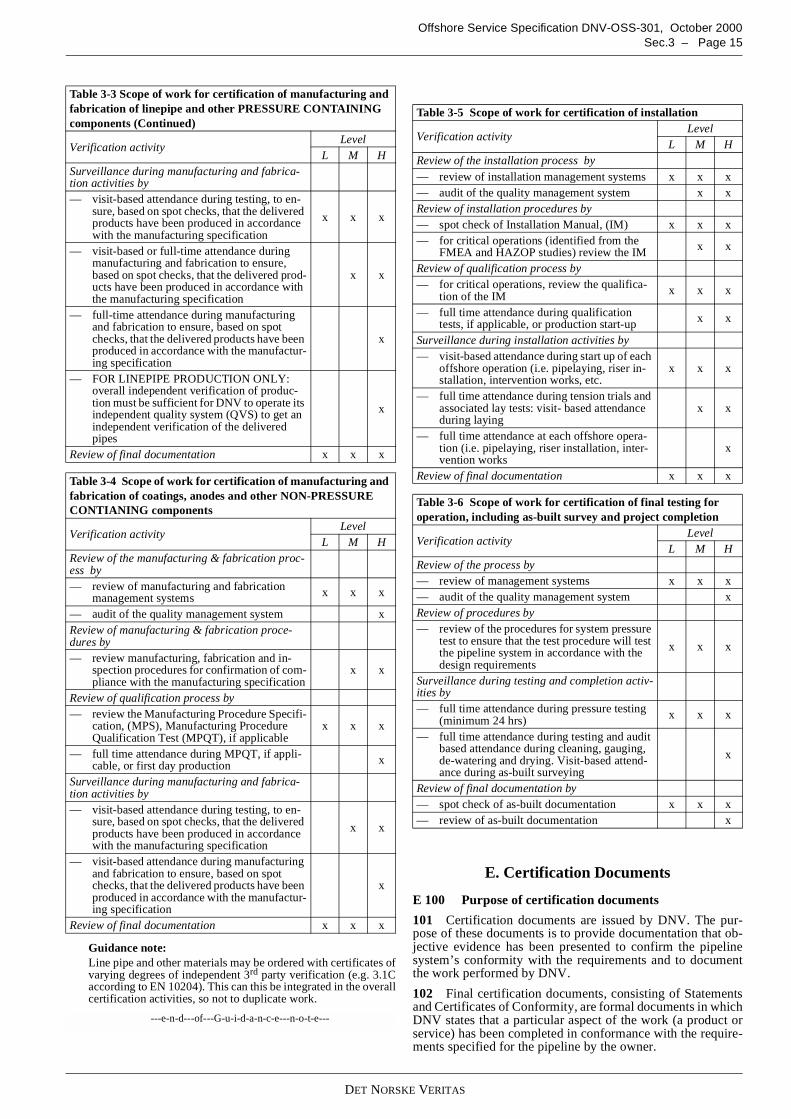
405 Definition of scope of work for certification of construc-tion shall follow Table 3-3 and Table 3-4 for manufacturingand fabrication, Table 3-5 for installation and Table D6 for fi-nal testing and completion.
Table 3-1 Scope of work for verification of overall projectmanagement
Verification activityLevel
L M HReview of the project management process by— review of project quality management docu-
mentation x x x
— audit of project quality management system x x— review of sub-contractor control x x— review of interface controls x x— review of methods of information flow x x
Table 3-2 Scope of work for certification of design
Verification activityLevel
L M HReview of the design process by— review of design quality management docu-
mentation x x x
— audit of design quality management system x xReview of specifications for design by— review of the design basis with emphasis of
the survey results and environmental data.Evaluation of the design criteria
x x x
— pipeline route and environmental conditions(DNV-OS-F101 Sec.3 C and D) x1) x1)
Review of design reports and drawings by— review of the main pipeline documentation to
ensure that the main load conditions havebeen accounted for in design, that the govern-ing conditions are identified, and that thechosen design philosophies are in accordancewith specified codes and standards
x x x
— evaluation of the main methods used and spotchecks of the input data and the calculationresults
x x
— detail review of main design reports xPerforming independent parallel calculations by— check of pressure containment x x x— simplified independent analysis/calcula-
tion(s) performed by spot checks x x
— advanced independent analysis/calcula-tion(s) performed by spot checks x
Review of specifications for construction and op-eration by— spot check of critical aspects x x x— review of main specifications x x
— thorough review of main specifications xReview of flow assurance (non-integrity as-pects(2)) by— general principles x x x— review of main documents supported by sim-
plified analyses x x
1) Verification activity to be agreed between owner and DNV case bycase considering aspects as:
— general knowledge of the area— criticality of the results.
2) These are optional certification services.
Table 3-3 Scope of work for certification of manufacturing andfabrication of linepipe and other PRESSURE CONTAININGcomponents
Verification activityLevel
L M HReview of the manufacturing & fabrication proc-ess by— review of manufacturing and fabrication
management systems x x x
— audit of the quality management system x xReview of manufacturing & fabrication proce-dures by— review manufacturing, fabrication and in-
spection procedures for confirmation of com-pliance with the manufacturing specification
x x x
— review method statements x xReview of qualification process by— review the Manufacturing Procedure Specifi-
cation, (MPS), Manufacturing ProcedureQualification Test (MPQT), if applicable
x x x
— full time attendance during MPQT, if appli-cable, or first day production x x
Table 3-2 Scope of work for certification of design (Continued)
Verification activityLevel
L M H
DET NORSKE VERITAS
Offshore Service Specification DNV-OSS-301, October 2000Sec.3 – Page 15
Guidance note:Line pipe and other materials may be ordered with certificates ofvarying degrees of independent 3rd party verification (e.g. 3.1Caccording to EN 10204). This can this be integrated in the overallcertification activities, so not to duplicate work.
---e-n-d---of---G-u-i-d-a-n-c-e---n-o-t-e---
E. Certification Documents
E 100 Purpose of certification documents
101 Certification documents are issued by DNV. The pur-pose of these documents is to provide documentation that ob-jective evidence has been presented to confirm the pipelinesystem’s conformity with the requirements and to documentthe work performed by DNV.
102 Final certification documents, consisting of Statementsand Certificates of Conformity, are formal documents in whichDNV states that a particular aspect of the work (a product orservice) has been completed in conformance with the require-ments specified for the pipeline by the owner.
Surveillance during manufacturing and fabrica-tion activities by— visit-based attendance during testing, to en-
sure, based on spot checks, that the deliveredproducts have been produced in accordancewith the manufacturing specification
x x x
— visit-based or full-time attendance duringmanufacturing and fabrication to ensure,based on spot checks, that the delivered prod-ucts have been produced in accordance withthe manufacturing specification
x x
— full-time attendance during manufacturingand fabrication to ensure, based on spotchecks, that the delivered products have beenproduced in accordance with the manufactur-ing specification
x
— FOR LINEPIPE PRODUCTION ONLY:overall independent verification of produc-tion must be sufficient for DNV to operate itsindependent quality system (QVS) to get anindependent verification of the deliveredpipes
x
Review of final documentation x x x
Table 3-4 Scope of work for certification of manufacturing andfabrication of coatings, anodes and other NON-PRESSURECONTIANING components
Verification activityLevel
L M HReview of the manufacturing & fabrication proc-ess by— review of manufacturing and fabrication
management systems x x x
— audit of the quality management system xReview of manufacturing & fabrication proce-dures by— review manufacturing, fabrication and in-
spection procedures for confirmation of com-pliance with the manufacturing specification
x x
Review of qualification process by— review the Manufacturing Procedure Specifi-
cation, (MPS), Manufacturing ProcedureQualification Test (MPQT), if applicable
x x x
— full time attendance during MPQT, if appli-cable, or first day production x
Surveillance during manufacturing and fabrica-tion activities by— visit-based attendance during testing, to en-
sure, based on spot checks, that the deliveredproducts have been produced in accordancewith the manufacturing specification
x x
— visit-based attendance during manufacturingand fabrication to ensure, based on spotchecks, that the delivered products have beenproduced in accordance with the manufactur-ing specification
x
Review of final documentation x x x
Table 3-3 Scope of work for certification of manufacturing andfabrication of linepipe and other PRESSURE CONTAININGcomponents (Continued)
Verification activityLevel
L M H
Table 3-5 Scope of work for certification of installation
Verification activityLevel
L M HReview of the installation process by
— review of installation management systems x x x— audit of the quality management system x xReview of installation procedures by— spot check of Installation Manual, (IM) x x x— for critical operations (identified from the
FMEA and HAZOP studies) review the IM x x
Review of qualification process by— for critical operations, review the qualifica-
tion of the IM x x x
— full time attendance during qualificationtests, if applicable, or production start-up x x
Surveillance during installation activities by— visit-based attendance during start up of each
offshore operation (i.e. pipelaying, riser in-stallation, intervention works, etc.
x x x
— full time attendance during tension trials andassociated lay tests: visit- based attendanceduring laying
x x
— full time attendance at each offshore opera-tion (i.e. pipelaying, riser installation, inter-vention works
x
Review of final documentation x x x
Table 3-6 Scope of work for certification of final testing foroperation, including as-built survey and project completion
Verification activityLevel
L M HReview of the process by— review of management systems x x x— audit of the quality management system xReview of procedures by— review of the procedures for system pressure
test to ensure that the test procedure will testthe pipeline system in accordance with thedesign requirements
x x x
Surveillance during testing and completion activ-ities by— full time attendance during pressure testing
(minimum 24 hrs) x x x
— full time attendance during testing and auditbased attendance during cleaning, gauging,de-watering and drying. Visit-based attend-ance during as-built surveying
x
Review of final documentation by— spot check of as-built documentation x x x— review of as-built documentation x
DET NORSKE VERITAS
Offshore Service Specification DNV-OSS-301, October 2000Page 16 – Sec.3
Guidance note:Examples of document forms are found in Appendix D.
---e-n-d---of---G-u-i-d-a-n-c-e---n-o-t-e---
103 Intermediate certification documents act as a form ofprogress reporting showing satisfactory completion of certifi-cation activities for various issues, items or phases of the pipe-line project.
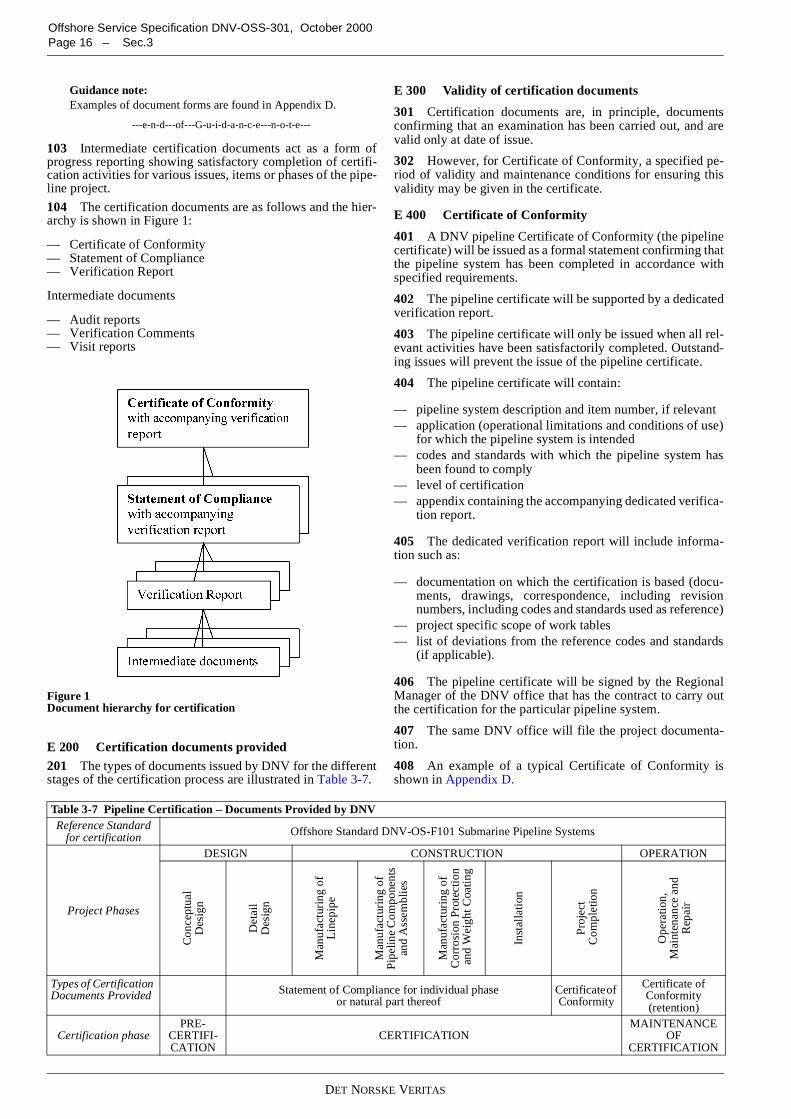
104 The certification documents are as follows and the hier-archy is shown in Figure 1:
— Certificate of Conformity— Statement of Compliance— Verification Report
Intermediate documents
— Audit reports— Verification Comments— Visit reports
Figure 1Document hierarchy for certification
E 200 Certification documents provided201 The types of documents issued by DNV for the differentstages of the certification process are illustrated in Table 3-7.
E 300 Validity of certification documents
301 Certification documents are, in principle, documentsconfirming that an examination has been carried out, and arevalid only at date of issue.
302 However, for Certificate of Conformity, a specified pe-riod of validity and maintenance conditions for ensuring thisvalidity may be given in the certificate.
E 400 Certificate of Conformity
401 A DNV pipeline Certificate of Conformity (the pipelinecertificate) will be issued as a formal statement confirming thatthe pipeline system has been completed in accordance withspecified requirements.
402 The pipeline certificate will be supported by a dedicatedverification report.
403 The pipeline certificate will only be issued when all rel-evant activities have been satisfactorily completed. Outstand-ing issues will prevent the issue of the pipeline certificate.
404 The pipeline certificate will contain:
— pipeline system description and item number, if relevant— application (operational limitations and conditions of use)
for which the pipeline system is intended— codes and standards with which the pipeline system has
been found to comply— level of certification— appendix containing the accompanying dedicated verifica-
tion report.
405 The dedicated verification report will include informa-tion such as:
— documentation on which the certification is based (docu-ments, drawings, correspondence, including revisionnumbers, including codes and standards used as reference)
— project specific scope of work tables— list of deviations from the reference codes and standards
(if applicable).
406 The pipeline certificate will be signed by the RegionalManager of the DNV office that has the contract to carry outthe certification for the particular pipeline system.
407 The same DNV office will file the project documenta-tion.
408 An example of a typical Certificate of Conformity isshown in Appendix D.
Table 3-7 Pipeline Certification – Documents Provided by DNVReference Standard
for certification Offshore Standard DNV-OS-F101 Submarine Pipeline Systems
Project Phases
DESIGN CONSTRUCTION OPERATION
Con
cept
ual
Des
ign
Det
ail
Des
ign
Man
ufac
turi
ngof
Lin
epip
e
Man
ufac
turi
ngof
Pip
elin
eC
ompo
nent
san
dA
ssem
blie
s
Man
ufac
turi
ngof
Cor
rosi
onP
rote
ctio
nan
dW
eigh
tCoa
ting
Inst
alla
tion
Pro
ject
Com
plet
ion
Ope
rati
on,
Mai
nten
ance
and
Rep
air
Types of CertificationDocuments Provided Statement of Compliance for individual phase
or natural part thereofCertificateofConformity
Certificate ofConformity(retention)
Certification phasePRE-
CERTIFI-CATION
CERTIFICATIONMAINTENANCE
OFCERTIFICATION

DET NORSKE VERITAS
Offshore Service Specification DNV-OSS-301, October 2000Sec.3 – Page 17
E 500 Statement of Compliance501 A Statement of Compliance can be issued on completionof each particular project phase, or natural part thereof, andwill be based on a dedicated verification report.
502 A Statement of Compliance will be issued as a formalstatement confirming that verification of documents and/or ac-tivities, has found that the pipeline system, a part thereof, or acertain activity, complies with the requirements applicable forthat particular project phase.
503 The technical information on a Statement of Compliancewill include information similar to that on the pipeline certifi-cate.
504 A Statement of Compliance will be signed by the DNVProject Manager.
505 An example of a typical Statement of Compliance isshown in Appendix D.
E 600 Verification reports601 Verification Reports are issued to confirm that the rele-vant product or service has been completed in accordance withspecified requirements.
602 The report will include information such as:
— product or service description and item number, if relevant— application (operational limitations and conditions of use)
for which the product or service is intended— codes and standards with which the product or service has
been verified against— clear statement of the conclusion from the verification
(does it or does it not meet the specified requirements)— codes and standards used as reference— documentation on which the verification report is based
(documents, drawings, correspondence, including revisionnumbers)
— project-specific scope of work tables— any comments— identification of any non-conformances.
603 The Verification Report will always be dated and havetwo signatures, the originator and the DNV internal verifier.
E 700 Verification comments701 Reviews of documents will be reported using Verifica-tion Comment Sheets (often called VerComs). These docu-ments give details to the client of aspects of pipeline designand construction that DNV:
— considers do not meet the specified requirements— does not have enough information to make a decision— offers advice based on its own experience.
Only in the first two instances does DNV expect a responsefrom the owner or its contractors.
702 An example of a typical Verification Comment sheet isshown in Appendix D.
E 800 Audit report801 Audit reports are issued to confirm that a company’squality management system has been reviewed to confirmcompliance (or not) with the nominated standard and projectrequirements. In addition, the audit reports confirm compli-ance with the documented procedures and that these proce-dures are effective.
802 Audit reports will contain information such as whether:
— the company has a documented quality system— this quality system has been certified by an accredited Cer-
tification Body for the product (or service) in question— the quality system covers the following quality assurance
elements adequately for the product:
— organisation— authority/responsibility— job descriptions for key persons— internal quality audits— documentation change control— job instructions/procedures— non-conformance/corrective action
— there are adequate procedures for activities such as:
— calibration of equipment— material identification and marking— control of special processes such as welding, NDT,
PWHT— non-conformance identification and handling— inspection status— final inspection
— the company’s facilities are, in general, considered ade-quate for the scope of supply
— a quality plan been prepared for the order concerned— the purchaser or their appointed inspection agency are
planned to attend the works— there are any problem areas identified.
803 An example of a typical audit report is shown in Appen-dix D
E 900 Visit reports
901 Visit reports are documentation/recording of attendanceactivity by DNV.
Guidance note:Visit reports are and may be called by different names. Examplesare Inspection Release Note, Survey Report, Inspection Certifi-cate, Site Report, etc.
---e-n-d---of---G-u-i-d-a-n-c-e---n-o-t-e---
902 A visit report will contain enough information to identi-fy clearly the product or service that has been examined, theoperating conditions or specifications to which it has been ex-amined and the conclusion reached by DNV.
903 The visit report will be printed on the relevant form andwill contain as much information as possible in accordancewith the standard headings in the form. In addition, the reportnumber shall be shown.
904 An example of a typical Visit Report is shown in Appen-dix D.
F. Use of Quality Management Systems
F 100 General
101 The assurance of pipeline integrity requires that grosserrors during design, construction and operation be minimised.The likelihood of gross errors shall be reduced in a systematicmanner by the operation of a quality management system ade-quate for the work being carried out. This is according toDNV-OS-F101 Sec.2 B500.
102 Quality management systems frequently are document-ed at three levels:
— the quality manual and related procedures document howthe organisation, as a whole, manages the quality of all itsproducts and services
— the quality plan documents the specific procedures relatedto a particular project
— the inspection and test plan documents how the qualitycontrol activities for a particular project shall be carriedout and recorded.
DET NORSKE VERITAS
Offshore Service Specification DNV-OSS-301, October 2000Page 18 – Sec.3
F 200 Quality plans
201 The basic function of a quality plan is as an aide mémoi-re in the management of a project. In an organisation withmany quality procedures for a variety of functions the qualityplan states those that are applicable to that particular project.The quality plan acts as a route map through the complexitiesof management of the project and highlights those activitiesrelevant to quality management.
202 The project quality plan normally consists of two parts;firstly, a narrative description of the means of controlling theproject, and secondly, a tabular description of the inspectionsand tests to be carried out during the work.
203 The quality plan should address:
— organisational details of the project— authorities and responsibilities of key personnel— interfaces between, the client, contractors, sub-contractors
and third parties— quality assurance activities placed on sub-contractors— cross references to existing company procedures.
204 The narrative part of the quality plan should include adescription of:
— the applicable standards— project organisation and responsibilities— review of the contractual requirements— project planning and progress reporting— procedures for such activities as design control, purchas-
ing, construction, installation, commissioning, interfacecontrol and auditing.
205 Additionally, the narrative part of the plan should de-scribe the documentation requirements It should be specified:
— what documents are required— at what stage these documents are required— who is responsible for preparing the documents— relevant parties to whom documents are submitted— how any necessary approvals are acquired— who has originals and who has copies— if copies have to be certified copies— the length of time documents are to be retained and by
whom.
F 300 Inspection and test plans301 The tabular description of the inspections and tests to becarried out during the work is frequently known as the inspec-tion and test plan.
302 The following items should be checked for inclusionwithin the inspection and test plan:
— each inspection and test point and its relative location inthe production cycle should be shown
— the characteristics to be inspected and tested at each pointshould be identified
— the use of sub-contractors should be indicated and detailsof how the verification of sub-contractor’s quality shall becarried out should be shown
— hold points established by the constructor, the operator ora third party, where witness or review of the selected in-spection or test is required, should be shown.
F 400 Review of quality management programme401 The contractor’s quality manual will be reviewed forcompliance with ISO 9001 or 9002 as appropriate. The con-tractor’s operations should be audited to establish compliancewith the documented system.
402 If the contractor has a quality system certified by an ac-credited third party certification body, this may be taken as ev-idence of a satisfactory quality system provided the certificate
is relevant to the contractor’s scope of work for the pipeline.However, the last two years’ periodical audit reports shall bereviewed to identify if any recurring non-conformities havebeen revealed.
403 Any weaknesses revealed during this audit, or review ofperiodical audit reports, shall be considered when planning thecontractor monitoring activities.
404 Surveillance of the continuing acceptability of the con-tractor’s quality management system is carried out by observ-ing a selection of audits carried out by the contractor as part ofits internal audit system. The audits to be observed should beselected over the length of the project at suitable intervals andshould cover as wide a selection of activities as possible.
405 Contractors’ inspection and test plans for the various ac-tivities undertaken during their scope of work for the pipelineshall be reviewed and accepted, if adequate.
G. Maintenance of Pipeline Certificate
G 100 General
101 During the operations phase, verification in order tomaintain the pipeline certificate is optional.
102 Maintenance of the pipeline certificate may only takeplace if the original pipeline certificate is issued with mainte-nance conditions.
G 200 Certificate of conformity with maintenance con-ditions
201 In addition to the requirements in Section 3 E400, thepipeline certificate will contain:
— conditions of validity— signature positions for confirmation of annual assessment.
G 300 Validity of certification documents
301 A prerequisite for the retention of validity of pipelinecertificates in the operations phase is that an in-service contracthas been established between the owner, or someone author-ised to act on his behalf, and DNV.
302 The period of validity of a certificate subject to exami-nation by DNV will not exceed 5 years. After that period thepipeline certificate may be reissued, provided a satisfactoryoverall condition assessment has been carried out.
303 The front page of pipeline certificates having a period ofvalidity will have a specific area to be signed by DNV annuallyshowing satisfactory completion of the annual assessments re-quired to continue the certificate’s validity. The pipeline certif-icate will become invalid if these signatures are not present
304 A verification report is issued after any modification orrepair of the pipeline system. No new Certificate of Conform-ity is required.
G 400 Maintaining the certificate
401 Pipeline systems in operation will retain their pipelinecertificate provided that:
— the pipeline system is operated within the specified limita-tions
— the owner provides adequate documentation from inspec-tion and maintenance activities
— the owner maintains any installed systems for conditionmonitoring and carries out condition evaluations as appli-cable
— information about damages, repairs and modifications,which may affect the certification, is promptly reported toDNV
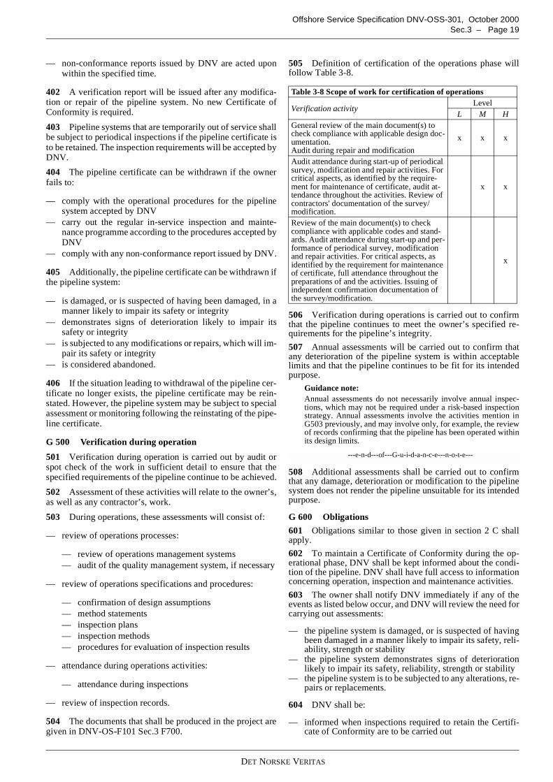
DET NORSKE VERITAS
Offshore Service Specification DNV-OSS-301, October 2000Sec.3 – Page 19
— non-conformance reports issued by DNV are acted uponwithin the specified time.
402 A verification report will be issued after any modifica-tion or repair of the pipeline system. No new Certificate ofConformity is required.
403 Pipeline systems that are temporarily out of service shallbe subject to periodical inspections if the pipeline certificate isto be retained. The inspection requirements will be accepted byDNV.
404 The pipeline certificate can be withdrawn if the ownerfails to:
— comply with the operational procedures for the pipelinesystem accepted by DNV
— carry out the regular in-service inspection and mainte-nance programme according to the procedures accepted byDNV
— comply with any non-conformance report issued by DNV.
405 Additionally, the pipeline certificate can be withdrawn ifthe pipeline system:
— is damaged, or is suspected of having been damaged, in amanner likely to impair its safety or integrity
— demonstrates signs of deterioration likely to impair itssafety or integrity
— is subjected to any modifications or repairs, which will im-pair its safety or integrity
— is considered abandoned.
406 If the situation leading to withdrawal of the pipeline cer-tificate no longer exists, the pipeline certificate may be rein-stated. However, the pipeline system may be subject to specialassessment or monitoring following the reinstating of the pipe-line certificate.
G 500 Verification during operation
501 Verification during operation is carried out by audit orspot check of the work in sufficient detail to ensure that thespecified requirements of the pipeline continue to be achieved.
502 Assessment of these activities will relate to the owner’s,as well as any contractor’s, work.
503 During operations, these assessments will consist of:
— review of operations processes:
— review of operations management systems— audit of the quality management system, if necessary
— review of operations specifications and procedures:
— confirmation of design assumptions— method statements— inspection plans— inspection methods— procedures for evaluation of inspection results
— attendance during operations activities:
— attendance during inspections
— review of inspection records.
504 The documents that shall be produced in the project aregiven in DNV-OS-F101 Sec.3 F700.
505 Definition of certification of the operations phase willfollow Table 3-8.
506 Verification during operations is carried out to confirmthat the pipeline continues to meet the owner’s specified re-quirements for the pipeline’s integrity.
507 Annual assessments will be carried out to confirm thatany deterioration of the pipeline system is within acceptablelimits and that the pipeline continues to be fit for its intendedpurpose.
Guidance note:Annual assessments do not necessarily involve annual inspec-tions, which may not be required under a risk-based inspectionstrategy. Annual assessments involve the activities mention inG503 previously, and may involve only, for example, the reviewof records confirming that the pipeline has been operated withinits design limits.
---e-n-d---of---G-u-i-d-a-n-c-e---n-o-t-e---
508 Additional assessments shall be carried out to confirmthat any damage, deterioration or modification to the pipelinesystem does not render the pipeline unsuitable for its intendedpurpose.
G 600 Obligations
601 Obligations similar to those given in section 2 C shallapply.
602 To maintain a Certificate of Conformity during the op-erational phase, DNV shall be kept informed about the condi-tion of the pipeline. DNV shall have full access to informationconcerning operation, inspection and maintenance activities.
603 The owner shall notify DNV immediately if any of theevents as listed below occur, and DNV will review the need forcarrying out assessments:
— the pipeline system is damaged, or is suspected of havingbeen damaged in a manner likely to impair its safety, reli-ability, strength or stability
— the pipeline system demonstrates signs of deteriorationlikely to impair its safety, reliability, strength or stability
— the pipeline system is to be subjected to any alterations, re-pairs or replacements.
604 DNV shall be:
— informed when inspections required to retain the Certifi-cate of Conformity are to be carried out
Table 3-8 Scope of work for certification of operations
Verification activityLevel
L M HGeneral review of the main document(s) tocheck compliance with applicable design doc-umentation.Audit during repair and modification
x x x
Audit attendance during start-up of periodicalsurvey, modification and repair activities. Forcritical aspects, as identified by the require-ment for maintenance of certificate, audit at-tendance throughout the activities. Review ofcontractors' documentation of the survey/modification.
x x
Review of the main document(s) to checkcompliance with applicable codes and stand-ards. Audit attendance during start-up and per-formance of periodical survey, modificationand repair activities. For critical aspects, asidentified by the requirement for maintenanceof certificate, full attendance throughout thepreparations of and the activities. Issuing ofindependent confirmation documentation ofthe survey/modification.
x
DET NORSKE VERITAS
Offshore Service Specification DNV-OSS-301, October 2000Page 20 – Sec.3
— given timely notification of occasions when such parts ofthe pipeline system, as are not normally accessible for in-spection, may be examined
— given timely advance notification of any pipeline repairactivities.
605 The owner shall provide DNV with the necessary plans,specifications and procedures for acceptance. DNV acceptanceis required for:
— operating and maintenance procedures and revisions tothem
— inspection programmes and requirements both routine andspecial
— inspection scopes of work— condition monitoring programmes— condition monitoring report findings and inspection re-
sults.
606 Once a non-conformance report is issued formally, thevalidity of the Certificate of Conformity is conditional on suc-cessful completion of the required action within the specifiedtime.
607 The owner shall notify DNV upon the fulfilment of anon-conformance correction, enabling DNV to carry out a ver-ification of the work.
608 DNV is responsible for, in a timely manner:
— carrying out the agreed assessments— issuing all reports and any necessary non-conformance re-
port.
G 700 Documentation hierarchy701 The certification documents for maintenance of certifi-cation are as follows:
— Certificate of Conformity— verification report— non-conformance reports.
G 800 Non-conformance report801 Where, after assessment of the pipeline system duringthe operations phase, DNV does not consider that items exam-ined meet the specified requirements, non-conformance re-ports are issued.
802 If no standard form is available, narrative reports con-taining all relevant information will be issued. This informa-tion shall enable precise identification of the area of DNV’sconcern.
803 No corrective action will be proposed by DNV, as this isthe owner’s responsibility.
DET NORSKE VERITAS
Offshore Service Specification DNV-OSS-301, October 2000App.A – Page 21
APPENDIX ASELECTION OF CERTIFICATION LEVEL
A. General
A 100 General principles101 The selection of the level of certification depends on thecriticality of each of the elements that have an impact on themanagement of risks to the pipeline system.
102 Certification shall direct greatest effort at those elementsof the pipeline system where the risk is highest and whose fail-ure or reduced performance will have the most significant im-pact on:
— safety risks— environmental risks— economic risks.
103 Suitable selection factors include, but are not limited to,the:
— Overall safety objectives for the pipeline system— Assessment of the risks associated with the pipeline and
the measures taken to reduce these risks— Degree of technical innovation in the pipeline system— Experience of the contractors in carrying out the work— Quality management systems of the owner and its contrac-
tors.
104 Due to the diversity of various pipeline systems, theircontents, their degree of innovation, the geographic location, etcetera, it is not possible to give precise guidelines on how todecide what level of certification is appropriate for each partic-ular pipeline system.
105 Therefore, guidance is given as a series of questions thatshould be answered when deciding the appropriate level of cer-tification for a pipeline system. This list is not exhaustive andother questions should be added to the list if appropriate for aparticular pipeline system.
106 It must be emphasised that the contribution of each ele-ment should be judged qualitatively and/or quantitatively.Wherever possible quantified risk assessment data should useto provide a justifiable basis for any decisions made.
107 Depending of the stage of the project, the activities maynot have taken place yet in which case the questions can alsobe posed in another form, i.e. “Is …. planned to be?”
B. Trigger Questions
B 100 Overall safety objective
— Does the safety objective address the main safety goals?— Does the safety objective establish acceptance criteria for
the level of risk acceptable to the owner?— Is this risk (depending on the pipeline and its location)
measured in terms of human injuries as well as environ-mental, economic and political consequences?
B 200 Assessment of risk
— Has a systematic review been carried out to identify andevaluate the probabilities and consequences of failures inthe pipeline system?
— Has this review judged the contribution of each elementqualitatively and quantitatively and used, where possible,quantified risk assessment data to provide a justifiable ba-sis for any decisions made?|
— Does the extent of the review reflect the criticality of thepipeline system, the planned operation and previous expe-rience with similar pipeline systems?
— Does this review identify the risk to the operation of thepipeline system and to the health and safety of personnelassociated with it or in its vicinity?
— Has the extent of the identified risks been reduced to a lev-el as low as reasonably practicable by means of one or bothof:
— reduction in the probability of failure— mitigation of the consequences of failure?
— Has the result of the systematic review of the risks beenmeasured against the owner’s safety objective?
— Has the result of this review been used in the selection ofthe appropriate certification activity level?
B 300 Technical innovation
— Has the degree of technical innovation in the pipeline sys-tem been considered?
— Has it been considered that risks to the pipeline are likelyto be greater with a high degree of technical innovationthan with a pipeline designed, manufactured and installedto well-known criteria in well-known waters?
— Have factors been considered in the selection of the appro-priate certification level such as:
— degree of difficulty in achieving technical require-ments
— knowledge of similar pipelines— effect of the new pipeline on the surrounding area?
B 400 Contractors’ experience
— Has the degree of risk to the pipeline system been consid-ered where design, construction or installation contractorsare inexperienced?
— Has the degree of risk been considered where the contrac-tors are experienced but not in similar work?
— Has the degree of risk been considered where the workschedule is tight?
B 500 Quality management systems
— Have all parties involved in the pipeline system imple-mented an adequate quality management system to ensurethat gross errors in the work are limited?
— Do these parties include the:
— owner— design contractor— construction contractors— installation contractor— operator?
— Do the factors being considered when evaluating the ade-quacy of the quality management system include:
— whether or not an ISO 9000 or equivalent certifiedsystem is in place
— results from external audits— results from internal audits— experience with contractors’ previous work— project work force familiarity with the quality man-
agement system?
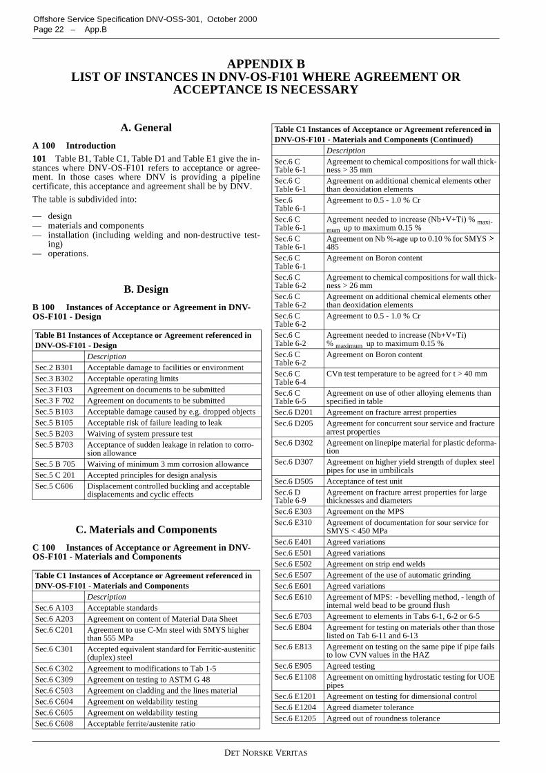
DET NORSKE VERITAS
Offshore Service Specification DNV-OSS-301, October 2000Page 22 – App.B
APPENDIX BLIST OF INSTANCES IN DNV-OS-F101 WHERE AGREEMENT OR
ACCEPTANCE IS NECESSARY
A. General
A 100 Introduction101 Table B1, Table C1, Table D1 and Table E1 give the in-stances where DNV-OS-F101 refers to acceptance or agree-ment. In those cases where DNV is providing a pipelinecertificate, this acceptance and agreement shall be by DNV.
The table is subdivided into:
— design— materials and components— installation (including welding and non-destructive test-
ing)— operations.
B. Design
B 100 Instances of Acceptance or Agreement in DNV-OS-F101 - Design
C. Materials and Components
C 100 Instances of Acceptance or Agreement in DNV-OS-F101 - Materials and Components
Table B1 Instances of Acceptance or Agreement referenced inDNV-OS-F101 - Design
DescriptionSec.2 B301 Acceptable damage to facilities or environmentSec.3 B302 Acceptable operating limitsSec.3 F103 Agreement on documents to be submittedSec.3 F 702 Agreement on documents to be submittedSec.5 B103 Acceptable damage caused by e.g. dropped objectsSec.5 B105 Acceptable risk of failure leading to leakSec.5 B203 Waiving of system pressure testSec.5 B703 Acceptance of sudden leakage in relation to corro-
sion allowanceSec.5 B 705 Waiving of minimum 3 mm corrosion allowanceSec.5 C 201 Accepted principles for design analysisSec.5 C606 Displacement controlled buckling and acceptable
displacements and cyclic effects
Table C1 Instances of Acceptance or Agreement referenced inDNV-OS-F101 - Materials and Components
DescriptionSec.6 A103 Acceptable standardsSec.6 A203 Agreement on content of Material Data SheetSec.6 C201 Agreement to use C-Mn steel with SMYS higher
than 555 MPaSec.6 C301 Accepted equivalent standard for Ferritic-austenitic
(duplex) steelSec.6 C302 Agreement to modifications to Tab 1-5Sec.6 C309 Agreement on testing to ASTM G 48Sec.6 C503 Agreement on cladding and the lines materialSec.6 C604 Agreement on weldability testingSec.6 C605 Agreement on weldability testingSec.6 C608 Acceptable ferrite/austenite ratio
Sec.6 CTable 6-1
Agreement to chemical compositions for wall thick-ness > 35 mm
Sec.6 CTable 6-1
Agreement on additional chemical elements otherthan deoxidation elements
Sec.6Table 6-1
Agreement to 0.5 - 1.0 % Cr
Sec.6 CTable 6-1
Agreement needed to increase (Nb+V+Ti) % maxi-mum up to maximum 0.15 %
Sec.6 CTable 6-1
Agreement on Nb %-age up to 0.10 % for SMYS �
485Sec.6 CTable 6-1
Agreement on Boron content
Sec.6 CTable 6-2
Agreement to chemical compositions for wall thick-ness > 26 mm
Sec.6 CTable 6-2
Agreement on additional chemical elements otherthan deoxidation elements
Sec.6 CTable 6-2
Agreement to 0.5 - 1.0 % Cr
Sec.6 CTable 6-2
Agreement needed to increase (Nb+V+Ti)% maximum up to maximum 0.15 %
Sec.6 CTable 6-2
Agreement on Boron content
Sec.6 CTable 6-4
CVn test temperature to be agreed for t > 40 mm
Sec.6 CTable 6-5
Agreement on use of other alloying elements thanspecified in table
Sec.6 D201 Agreement on fracture arrest propertiesSec.6 D205 Agreement for concurrent sour service and fracture
arrest propertiesSec.6 D302 Agreement on linepipe material for plastic deforma-
tionSec.6 D307 Agreement on higher yield strength of duplex steel
pipes for use in umbilicalsSec.6 D505 Acceptance of test unitSec.6 DTable 6-9
Agreement on fracture arrest properties for largethicknesses and diameters
Sec.6 E303 Agreement on the MPSSec.6 E310 Agreement of documentation for sour service for
SMYS < 450 MPaSec.6 E401 Agreed variationsSec.6 E501 Agreed variationsSec.6 E502 Agreement on strip end weldsSec.6 E507 Agreement of the use of automatic grindingSec.6 E601 Agreed variationsSec.6 E610 Agreement of MPS: - bevelling method, - length of
internal weld bead to be ground flushSec.6 E703 Agreement to elements in Tabs 6-1, 6-2 or 6-5Sec.6 E804 Agreement for testing on materials other than those
listed on Tab 6-11 and 6-13Sec.6 E813 Agreement on testing on the same pipe if pipe fails
to low CVN values in the HAZSec.6 E905 Agreed testingSec.6 E1108 Agreement on omitting hydrostatic testing for UOE
pipesSec.6 E1201 Agreement on testing for dimensional controlSec.6 E1204 Agreed diameter toleranceSec.6 E1205 Agreed out of roundness tolerance
Table C1 Instances of Acceptance or Agreement referenced inDNV-OS-F101 - Materials and Components (Continued)
Description
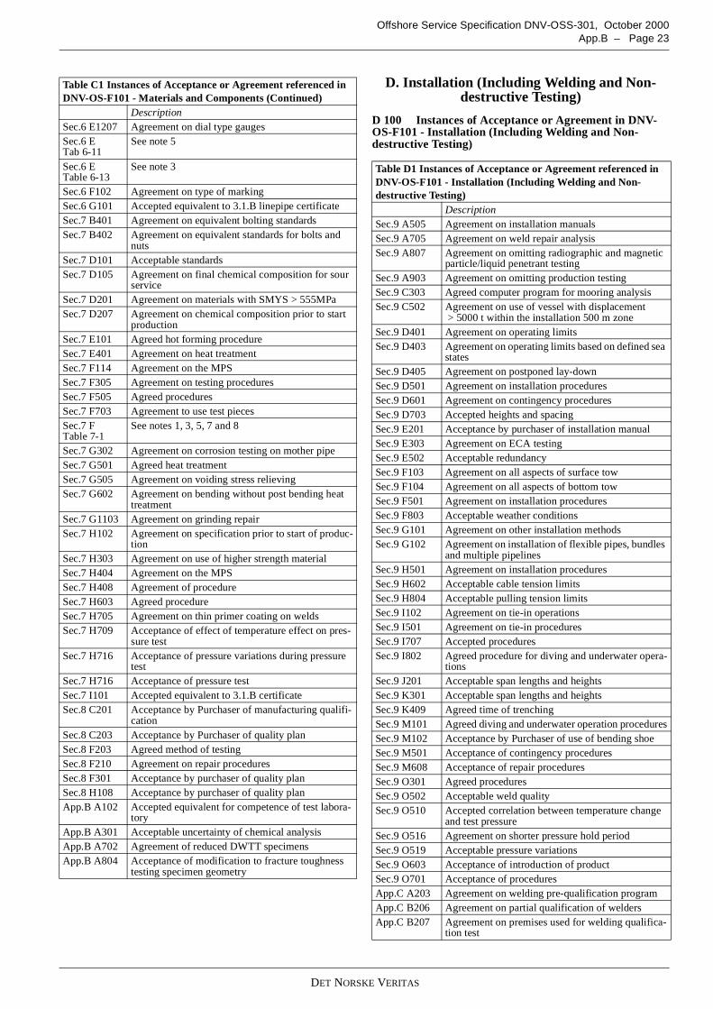
DET NORSKE VERITAS
Offshore Service Specification DNV-OSS-301, October 2000App.B – Page 23
D. Installation (Including Welding and Non-destructive Testing)
D 100 Instances of Acceptance or Agreement in DNV-OS-F101 - Installation (Including Welding and Non-destructive Testing)
Sec.6 E1207 Agreement on dial type gaugesSec.6 ETab 6-11
See note 5
Sec.6 ETable 6-13
See note 3
Sec.6 F102 Agreement on type of markingSec.6 G101 Accepted equivalent to 3.1.B linepipe certificateSec.7 B401 Agreement on equivalent bolting standardsSec.7 B402 Agreement on equivalent standards for bolts and
nutsSec.7 D101 Acceptable standardsSec.7 D105 Agreement on final chemical composition for sour
serviceSec.7 D201 Agreement on materials with SMYS > 555MPaSec.7 D207 Agreement on chemical composition prior to start
productionSec.7 E101 Agreed hot forming procedureSec.7 E401 Agreement on heat treatmentSec.7 F114 Agreement on the MPSSec.7 F305 Agreement on testing proceduresSec.7 F505 Agreed proceduresSec.7 F703 Agreement to use test piecesSec.7 FTable 7-1
See notes 1, 3, 5, 7 and 8
Sec.7 G302 Agreement on corrosion testing on mother pipeSec.7 G501 Agreed heat treatmentSec.7 G505 Agreement on voiding stress relievingSec.7 G602 Agreement on bending without post bending heat
treatmentSec.7 G1103 Agreement on grinding repairSec.7 H102 Agreement on specification prior to start of produc-
tionSec.7 H303 Agreement on use of higher strength materialSec.7 H404 Agreement on the MPSSec.7 H408 Agreement of procedureSec.7 H603 Agreed procedureSec.7 H705 Agreement on thin primer coating on weldsSec.7 H709 Acceptance of effect of temperature effect on pres-
sure testSec.7 H716 Acceptance of pressure variations during pressure
testSec.7 H716 Acceptance of pressure testSec.7 I101 Accepted equivalent to 3.1.B certificateSec.8 C201 Acceptance by Purchaser of manufacturing qualifi-
cationSec.8 C203 Acceptance by Purchaser of quality planSec.8 F203 Agreed method of testingSec.8 F210 Agreement on repair proceduresSec.8 F301 Acceptance by purchaser of quality planSec.8 H108 Acceptance by purchaser of quality planApp.B A102 Accepted equivalent for competence of test labora-
toryApp.B A301 Acceptable uncertainty of chemical analysisApp.B A702 Agreement of reduced DWTT specimensApp.B A804 Acceptance of modification to fracture toughness
testing specimen geometry
Table C1 Instances of Acceptance or Agreement referenced inDNV-OS-F101 - Materials and Components (Continued)
Description
Table D1 Instances of Acceptance or Agreement referenced inDNV-OS-F101 - Installation (Including Welding and Non-destructive Testing)
DescriptionSec.9 A505 Agreement on installation manualsSec.9 A705 Agreement on weld repair analysisSec.9 A807 Agreement on omitting radiographic and magnetic
particle/liquid penetrant testingSec.9 A903 Agreement on omitting production testingSec.9 C303 Agreed computer program for mooring analysisSec.9 C502 Agreement on use of vessel with displacement
> 5000 t within the installation 500 m zoneSec.9 D401 Agreement on operating limitsSec.9 D403 Agreement on operating limits based on defined sea
statesSec.9 D405 Agreement on postponed lay-downSec.9 D501 Agreement on installation proceduresSec.9 D601 Agreement on contingency proceduresSec.9 D703 Accepted heights and spacingSec.9 E201 Acceptance by purchaser of installation manualSec.9 E303 Agreement on ECA testingSec.9 E502 Acceptable redundancySec.9 F103 Agreement on all aspects of surface towSec.9 F104 Agreement on all aspects of bottom towSec.9 F501 Agreement on installation proceduresSec.9 F803 Acceptable weather conditionsSec.9 G101 Agreement on other installation methodsSec.9 G102 Agreement on installation of flexible pipes, bundles
and multiple pipelinesSec.9 H501 Agreement on installation proceduresSec.9 H602 Acceptable cable tension limitsSec.9 H804 Acceptable pulling tension limitsSec.9 I102 Agreement on tie-in operationsSec.9 I501 Agreement on tie-in proceduresSec.9 I707 Accepted proceduresSec.9 I802 Agreed procedure for diving and underwater opera-
tionsSec.9 J201 Acceptable span lengths and heightsSec.9 K301 Acceptable span lengths and heightsSec.9 K409 Agreed time of trenchingSec.9 M101 Agreed diving and underwater operation proceduresSec.9 M102 Acceptance by Purchaser of use of bending shoeSec.9 M501 Acceptance of contingency proceduresSec.9 M608 Acceptance of repair proceduresSec.9 O301 Agreed proceduresSec.9 O502 Acceptable weld qualitySec.9 O510 Accepted correlation between temperature change
and test pressureSec.9 O516 Agreement on shorter pressure hold periodSec.9 O519 Acceptable pressure variationsSec.9 O603 Acceptance of introduction of productSec.9 O701 Acceptance of proceduresApp.C A203 Agreement on welding pre-qualification programApp.C B206 Agreement on partial qualification of weldersApp.C B207 Agreement on premises used for welding qualifica-
tion test
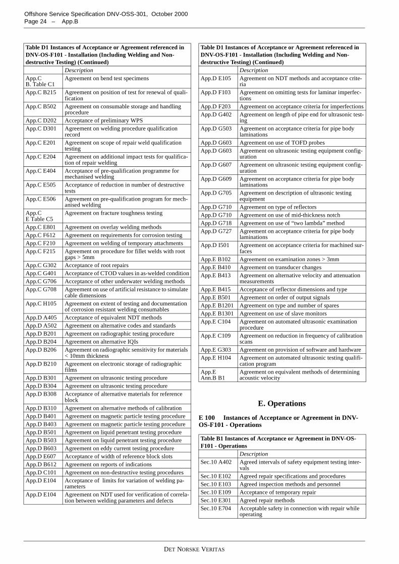
DET NORSKE VERITAS
Offshore Service Specification DNV-OSS-301, October 2000Page 24 – App.B
E. Operations
E 100 Instances of Acceptance or Agreement in DNV-OS-F101 - Operations
App.CB. Table C1
Agreement on bend test specimens
App.C B215 Agreement on position of test for renewal of quali-fication
App.C B502 Agreement on consumable storage and handlingprocedure
App.C D202 Acceptance of preliminary WPSApp.C D301 Agreement on welding procedure qualification
recordApp.C E201 Agreement on scope of repair weld qualification
testingApp.C E204 Agreement on additional impact tests for qualifica-
tion of repair weldingApp.C E404 Acceptance of pre-qualification programme for
mechanised weldingApp.C E505 Acceptance of reduction in number of destructive
testsApp.C E506 Agreement on pre-qualification program for mech-
anised weldingApp.CE Table C5
Agreement on fracture toughness testing
App.C E801 Agreement on overlay welding methodsApp.C F612 Agreement on requirements for corrosion testingApp.C F210 Agreement on welding of temporary attachmentsApp.C F215 Agreement on procedure for fillet welds with root
gaps > 5mmApp.C G302 Acceptance of root repairsApp.C G401 Acceptance of CTOD values in as-welded conditionApp.C G706 Acceptance of other underwater welding methodsApp.C G708 Agreement on use of artificial resistance to simulate
cable dimensionsApp.C H105 Agreement on extent of testing and documentation
of corrosion resistant welding consumablesApp.D A405 Acceptance of equivalent NDT methodsApp.D A502 Agreement on alternative codes and standardsApp.D B201 Agreement on radiographic testing procedureApp.D B204 Agreement on alternative IQIsApp.D B206 Agreement on radiographic sensitivity for materials
< 10mm thicknessApp.D B210 Agreement on electronic storage of radiographic
filmsApp.D B301 Agreement on ultrasonic testing procedureApp.D B304 Agreement on ultrasonic testing procedureApp.D B308 Acceptance of alternative materials for reference
blockApp.D B310 Agreement on alternative methods of calibrationApp.D B401 Agreement on magnetic particle testing procedureApp.D B403 Agreement on magnetic particle testing procedureApp.D B501 Agreement on liquid penetrant testing procedureApp.D B503 Agreement on liquid penetrant testing procedureApp.D B603 Agreement on eddy current testing procedureApp.D E607 Acceptance of width of reference block slotsApp.D B612 Agreement on reports of indicationsApp.D C101 Agreement on non-destructive testing proceduresApp.D E104 Acceptance of limits for variation of welding pa-
rametersApp.D E104 Agreement on NDT used for verification of correla-
tion between welding parameters and defects
Table D1 Instances of Acceptance or Agreement referenced inDNV-OS-F101 - Installation (Including Welding and Non-destructive Testing) (Continued)
DescriptionApp.D E105 Agreement on NDT methods and acceptance crite-
riaApp.D F103 Agreement on omitting tests for laminar imperfec-
tionsApp.D F203 Agreement on acceptance criteria for imperfectionsApp.D G402 Agreement on length of pipe end for ultrasonic test-
ingApp.D G503 Agreement on acceptance criteria for pipe body
laminationsApp.D G603 Agreement on use of TOFD probesApp.D G603 Agreement on ultrasonic testing equipment config-
urationApp.D G607 Agreement on ultrasonic testing equipment config-
urationApp.D G609 Agreement on acceptance criteria for pipe body
laminationsApp.D G705 Agreement on description of ultrasonic testing
equipmentApp.D G710 Agreement on type of reflectorsApp.D G710 Agreement on use of mid-thickness notchApp.D G718 Agreement on use of “two lambda” methodApp.D G727 Agreement on acceptance criteria for pipe body
laminationsApp.D I501 Agreement on acceptance criteria for machined sur-
facesApp.E B102 Agreement on examination zones > 3mmApp.E B410 Agreement on transducer changesApp.E B413 Agreement on alternative velocity and attenuation
measurementsApp.E B415 Acceptance of reflector dimensions and typeApp.E B501 Agreement on order of output signalsApp.E B1201 Agreement on type and number of sparesApp.E B1301 Agreement on use of slave monitorsApp.E C104 Agreement on automated ultrasonic examination
procedureApp.E C109 Agreement on reduction in frequency of calibration
scansApp.E G303 Agreement on provision of software and hardwareApp.E H104 Agreement on automated ultrasonic testing qualifi-
cation programApp.EAnn.B B1
Agreement on equivalent methods of determiningacoustic velocity
Table B1 Instances of Acceptance or Agreement in DNV-OS-F101 - Operations
DescriptionSec.10 A402 Agreed intervals of safety equipment testing inter-
valsSec.10 E102 Agreed repair specifications and proceduresSec.10 E103 Agreed inspection methods and personnelSec.10 E109 Acceptance of temporary repairSec.10 E301 Agreed repair methodsSec.10 E704 Acceptable safety in connection with repair while
operating
Table D1 Instances of Acceptance or Agreement referenced inDNV-OS-F101 - Installation (Including Welding and Non-destructive Testing) (Continued)
Description
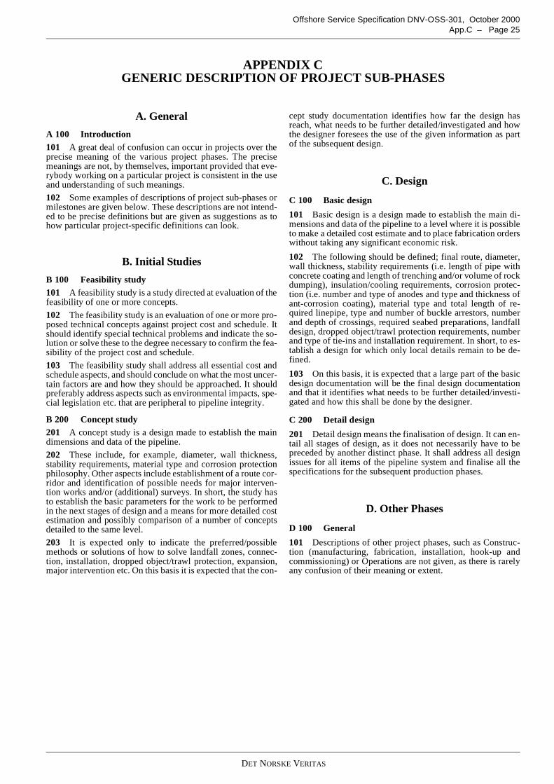
DET NORSKE VERITAS
Offshore Service Specification DNV-OSS-301, October 2000App.C – Page 25
APPENDIX CGENERIC DESCRIPTION OF PROJECT SUB-PHASES
A. General
A 100 Introduction101 A great deal of confusion can occur in projects over theprecise meaning of the various project phases. The precisemeanings are not, by themselves, important provided that eve-rybody working on a particular project is consistent in the useand understanding of such meanings.
102 Some examples of descriptions of project sub-phases ormilestones are given below. These descriptions are not intend-ed to be precise definitions but are given as suggestions as tohow particular project-specific definitions can look.
B. Initial Studies
B 100 Feasibility study101 A feasibility study is a study directed at evaluation of thefeasibility of one or more concepts.
102 The feasibility study is an evaluation of one or more pro-posed technical concepts against project cost and schedule. Itshould identify special technical problems and indicate the so-lution or solve these to the degree necessary to confirm the fea-sibility of the project cost and schedule.
103 The feasibility study shall address all essential cost andschedule aspects, and should conclude on what the most uncer-tain factors are and how they should be approached. It shouldpreferably address aspects such as environmental impacts, spe-cial legislation etc. that are peripheral to pipeline integrity.
B 200 Concept study201 A concept study is a design made to establish the maindimensions and data of the pipeline.
202 These include, for example, diameter, wall thickness,stability requirements, material type and corrosion protectionphilosophy. Other aspects include establishment of a route cor-ridor and identification of possible needs for major interven-tion works and/or (additional) surveys. In short, the study hasto establish the basic parameters for the work to be performedin the next stages of design and a means for more detailed costestimation and possibly comparison of a number of conceptsdetailed to the same level.
203 It is expected only to indicate the preferred/possiblemethods or solutions of how to solve landfall zones, connec-tion, installation, dropped object/trawl protection, expansion,major intervention etc. On this basis it is expected that the con-
cept study documentation identifies how far the design hasreach, what needs to be further detailed/investigated and howthe designer foresees the use of the given information as partof the subsequent design.
C. Design
C 100 Basic design
101 Basic design is a design made to establish the main di-mensions and data of the pipeline to a level where it is possibleto make a detailed cost estimate and to place fabrication orderswithout taking any significant economic risk.
102 The following should be defined; final route, diameter,wall thickness, stability requirements (i.e. length of pipe withconcrete coating and length of trenching and/or volume of rockdumping), insulation/cooling requirements, corrosion protec-tion (i.e. number and type of anodes and type and thickness ofant-corrosion coating), material type and total length of re-quired linepipe, type and number of buckle arrestors, numberand depth of crossings, required seabed preparations, landfalldesign, dropped object/trawl protection requirements, numberand type of tie-ins and installation requirement. In short, to es-tablish a design for which only local details remain to be de-fined.
103 On this basis, it is expected that a large part of the basicdesign documentation will be the final design documentationand that it identifies what needs to be further detailed/investi-gated and how this shall be done by the designer.
C 200 Detail design
201 Detail design means the finalisation of design. It can en-tail all stages of design, as it does not necessarily have to bepreceded by another distinct phase. It shall address all designissues for all items of the pipeline system and finalise all thespecifications for the subsequent production phases.
D. Other Phases
D 100 General
101 Descriptions of other project phases, such as Construc-tion (manufacturing, fabrication, installation, hook-up andcommissioning) or Operations are not given, as there is rarelyany confusion of their meaning or extent.
DET NORSKE VERITAS
Offshore Service Specification DNV-OSS-301, October 2000Page 26 – App.D
APPENDIX DEXAMPLES OF CERTIFICATION DOCUMENTS
A. General
A 100 Introduction101 This appendix includes example forms for use by DNVin the verification and certificate of pipeline systems.
102 The following forms are included:
— Certificate of Conformity— Statement of Compliance— Verification Comments Sheet— Audit Report— Visit Report
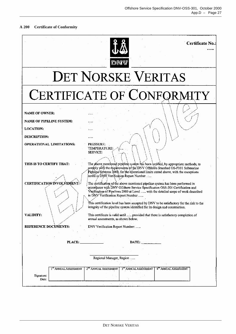
DET NORSKE VERITAS
Offshore Service Specification DNV-OSS-301, October 2000App.D – Page 27
A 200 Certificate of Conformity
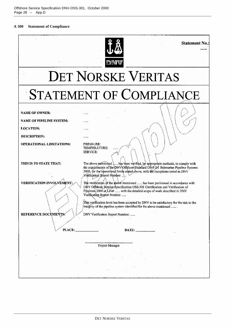
DET NORSKE VERITAS
Offshore Service Specification DNV-OSS-301, October 2000Page 28 – App.D
A 300 Statement of Compliance
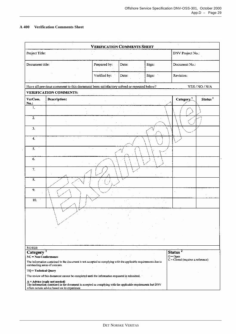
DET NORSKE VERITAS
Offshore Service Specification DNV-OSS-301, October 2000App.D – Page 29
A 400 Verification Comments Sheet
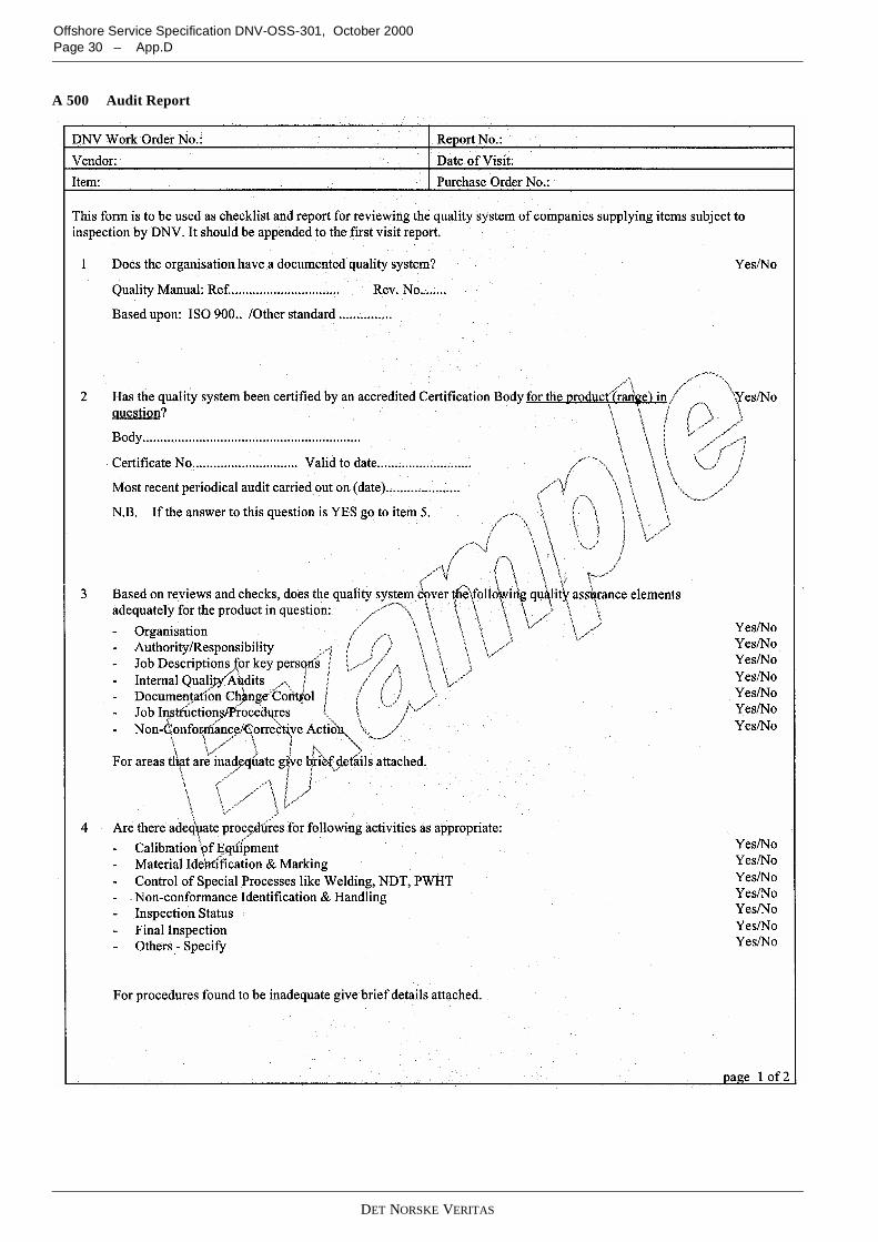
DET NORSKE VERITAS
Offshore Service Specification DNV-OSS-301, October 2000Page 30 – App.D
A 500 Audit Report
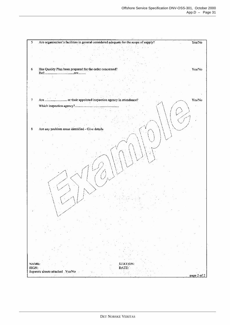
DET NORSKE VERITAS
Offshore Service Specification DNV-OSS-301, October 2000App.D – Page 31

DET NORSKE VERITAS
Offshore Service Specification DNV-OSS-301, October 2000Page 32 – App.D
A 600 Visit Report
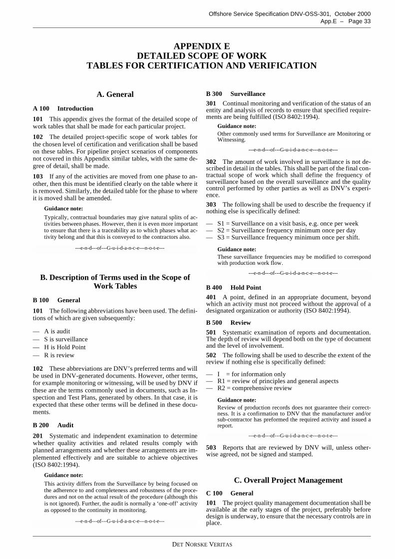
DET NORSKE VERITAS
Offshore Service Specification DNV-OSS-301, October 2000App.E – Page 33
APPENDIX EDETAILED SCOPE OF WORK
TABLES FOR CERTIFICATION AND VERIFICATION
A. General
A 100 Introduction
101 This appendix gives the format of the detailed scope ofwork tables that shall be made for each particular project.
102 The detailed project-specific scope of work tables forthe chosen level of certification and verification shall be basedon these tables. For pipeline project scenarios of componentsnot covered in this Appendix similar tables, with the same de-gree of detail, shall be made.
103 If any of the activities are moved from one phase to an-other, then this must be identified clearly on the table where itis removed. Similarly, the detailed table for the phase to whereit is moved shall be amended.
Guidance note:
Typically, contractual boundaries may give natural splits of ac-tivities between phases. However, then it is even more importantto ensure that there is a traceability as to which phases what ac-tivity belong and that this is conveyed to the contractors also.
---e-n-d---of---G-u-i-d-a-n-c-e---n-o-t-e---
B. Description of Terms used in the Scope ofWork Tables
B 100 General
101 The following abbreviations have been used. The defini-tions of which are given subsequently:
— A is audit— S is surveillance— H is Hold Point— R is review
102 These abbreviations are DNV’s preferred terms and willbe used in DNV-generated documents. However, other terms,for example monitoring or witnessing, will be used by DNV ifthese are the terms commonly used in documents, such as In-spection and Test Plans, generated by others. In that case, it isexpected that these other terms will be defined in these docu-ments.
B 200 Audit
201 Systematic and independent examination to determinewhether quality activities and related results comply withplanned arrangements and whether these arrangements are im-plemented effectively and are suitable to achieve objectives(ISO 8402:1994).
Guidance note:
This activity differs from the Surveillance by being focused onthe adherence to and completeness and robustness of the proce-dures and not on the actual result of the procedure (although thisis not ignored). Further, the audit is normally a ‘one-off’ activityas opposed to the continuity in monitoring.
---e-n-d---of---G-u-i-d-a-n-c-e---n-o-t-e---
B 300 Surveillance
301 Continual monitoring and verification of the status of anentity and analysis of records to ensure that specified require-ments are being fulfilled (ISO 8402:1994).
Guidance note:Other commonly used terms for Surveillance are Monitoring orWitnessing.
---e-n-d---of---G-u-i-d-a-n-c-e---n-o-t-e---
302 The amount of work involved in surveillance is not de-scribed in detail in the tables. This shall be part of the final con-tractual scope of work which shall define the frequency ofsurveillance based on the overall surveillance and the qualitycontrol performed by other parties as well as DNV’s experi-ence.
303 The following shall be used to describe the frequency ifnothing else is specifically defined:
— S1 = Surveillance on a visit basis, e.g. once per week— S2 = Surveillance frequency minimum once per day— S3 = Surveillance frequency minimum once per shift.
Guidance note:These surveillance frequencies may be modified to correspondwith production work flow.
---e-n-d---of---G-u-i-d-a-n-c-e---n-o-t-e---
B 400 Hold Point
401 A point, defined in an appropriate document, beyondwhich an activity must not proceed without the approval of adesignated organization or authority (ISO 8402:1994).
B 500 Review
501 Systematic examination of reports and documentation.The depth of review will depend both on the type of documentand the level of involvement.
502 The following shall be used to describe the extent of thereview if nothing else is specifically defined:
— I = for information only— R1 = review of principles and general aspects— R2 = comprehensive review
Guidance note:Review of production records does not guarantee their correct-ness. It is a confirmation to DNV that the manufacturer and/orsub-contractor has preformed the required activity and issued areport.
---e-n-d---of---G-u-i-d-a-n-c-e---n-o-t-e---
503 Reports that are reviewed by DNV will, unless other-wise agreed, not be signed and stamped.
C. Overall Project Management
C 100 General
101 The project quality management documentation shall beavailable at the early stages of the project, preferably beforedesign is underway, to ensure that the necessary controls are inplace.
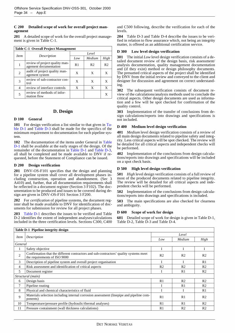
DET NORSKE VERITAS
Offshore Service Specification DNV-OSS-301, October 2000Page 34 – App.E
C 200 Detailed scope of work for overall project man-agement201 A detailed scope of work for the overall project manage-ment is given in Table C-1.
D. Design
D 100 General101 For design verification a list similar to that given in Ta-ble D-1 and Table D-3 shall be made for the specifics of theminimum requirement to documentation for each pipeline sys-tem.
102 The documentation of the items under General in TableD-1 shall be available at the early stages of the design. Of theremainder of the documentation in Table D-1 and Table D-3,all shall be completed and be made available to DNV if re-quested, before the Statement of Compliance can be issued.
D 200 Design verification201 DNV-OS-F101 specifies that the design and planningfor a pipeline system shall cover all development phases in-cluding construction, operation and abandonment. (Sec 3A410) and, further, that all documentation requirements shallbe reflected in a document register (Section 3 F102). The doc-umentation to be produced and issues to be covered during de-sign are given in DNV-OS-F101 Section 3 F200.
202 For certification of pipeline systems, the document reg-ister shall be made available to DNV for identification of doc-uments for submission for review for all project phases.
203 Table D-1 describes the issues to be verified and TableD-2 identifies the extent of independent analyses/calculationsincluded in the three certification levels. Sections C300, C400
and C500 following, describe the verification for each of thelevels.
204 Table D-3 and Table D-4 describe the issues to be veri-fied in relation to flow assurance which, not being an integritymatter, is offered as an additional certification service.
D 300 Low level design verification301 The initial Low level design verification consists of a de-tailed document review of the design basis, risk assessment/analysis documentation, quality management documentationand (if they exist) method or design philosophy documents.The presumed critical aspects of the project shall be identifiedby DNV from the initial review and conveyed to the client anddesigner for discussion and agreement on correct understand-ing.
302 The subsequent verification consists of document re-view of the calculations/analysis methods used to conclude thecritical aspects. Other design documents are used as informa-tion and a few will be spot checked for confirmation of thequality control.
303 Implementation of the transfer of conclusions from de-sign calculations/reports into drawings and specifications isnot included.
D 400 Medium level design verification401 Medium level design verification consists of a review ofall main design documents related to pipeline safety and integ-rity. Less critical aspects will be spot checked. The review willbe detailed for all critical aspects and independent checks willbe performed.
402 Implementation of the conclusions from design calcula-tions/reports into drawings and specifications will be includedon a spot check basis.
D 500 High level design verification501 High level design verification consists of a full review ofmost of the produced documents related to pipeline integrity.The review will be detailed for all critical aspects and inde-pendent checks will be performed.
502 Implementation of the conclusions from design calcula-tions/reports into drawings and specifications is included.
503 The main specifications are also checked for clearnessand ambiguity.
D 600 Scope of work for design601 Detailed scope of work for design is given in Table D-1,Table D-2, Table D-3 and Table D-4.
Table C-1 Overall Project Management
Item DescriptionLevel
Low Medium High
1 review of project quality man-agement documentation R1 R2 R2
2 audit of project quality man-agement system X X X
3 review of sub-contractor con-trol X X X
4 review of interface controls X X X
5 review of methods of infor-mation flow X
Table D-1 Pipeline integrity design
Item DescriptionLevel
Low Medium HighGeneral
1 Safety objective I I I
2 Confirmation that the different contractors and sub-contractors’ quality systems meetthe requirements of ISO 9000 R2 R2 R2
3 Description of pipeline system and overall project organisation I I R14 Risk assessment and identification of critical aspects R2 R2 R25 Document register I R1 R2
Structural (main)6 Design basis R1 R2 R27 Pipeline routing I R1 R28 Physical and chemical characteristics of fluid I I R1
9 Materials selection including internal corrosion assessment (linepipe and pipeline com-ponents) R1 R1 R2
10 Temperature/pressure profile (hydraulic/thermal analyses) R1 R1 R211 Pressure containment (wall thickness calculations) R1 R2 R2
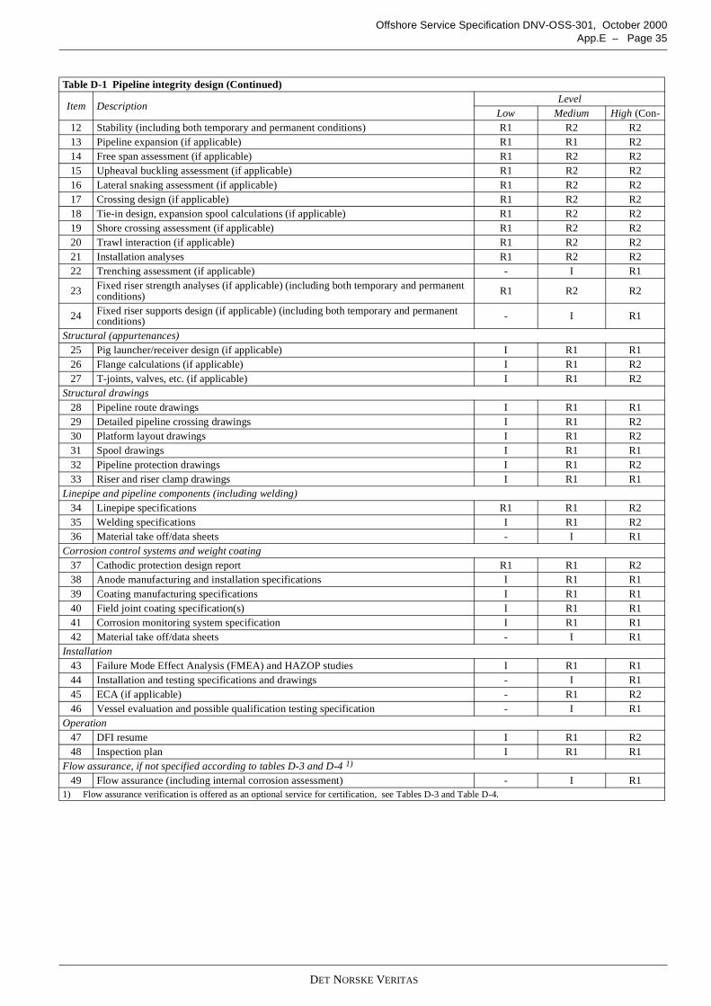
DET NORSKE VERITAS
Offshore Service Specification DNV-OSS-301, October 2000App.E – Page 35
12 Stability (including both temporary and permanent conditions) R1 R2 R213 Pipeline expansion (if applicable) R1 R1 R214 Free span assessment (if applicable) R1 R2 R215 Upheaval buckling assessment (if applicable) R1 R2 R216 Lateral snaking assessment (if applicable) R1 R2 R217 Crossing design (if applicable) R1 R2 R218 Tie-in design, expansion spool calculations (if applicable) R1 R2 R219 Shore crossing assessment (if applicable) R1 R2 R220 Trawl interaction (if applicable) R1 R2 R221 Installation analyses R1 R2 R222 Trenching assessment (if applicable) - I R1
23 Fixed riser strength analyses (if applicable) (including both temporary and permanentconditions) R1 R2 R2
24 Fixed riser supports design (if applicable) (including both temporary and permanentconditions) - I R1
Structural (appurtenances)25 Pig launcher/receiver design (if applicable) I R1 R126 Flange calculations (if applicable) I R1 R227 T-joints, valves, etc. (if applicable) I R1 R2
Structural drawings28 Pipeline route drawings I R1 R129 Detailed pipeline crossing drawings I R1 R230 Platform layout drawings I R1 R231 Spool drawings I R1 R132 Pipeline protection drawings I R1 R233 Riser and riser clamp drawings I R1 R1
Linepipe and pipeline components (including welding)34 Linepipe specifications R1 R1 R235 Welding specifications I R1 R236 Material take off/data sheets - I R1
Corrosion control systems and weight coating37 Cathodic protection design report R1 R1 R238 Anode manufacturing and installation specifications I R1 R139 Coating manufacturing specifications I R1 R140 Field joint coating specification(s) I R1 R141 Corrosion monitoring system specification I R1 R142 Material take off/data sheets - I R1
Installation43 Failure Mode Effect Analysis (FMEA) and HAZOP studies I R1 R144 Installation and testing specifications and drawings - I R145 ECA (if applicable) - R1 R246 Vessel evaluation and possible qualification testing specification - I R1
Operation47 DFI resume I R1 R248 Inspection plan I R1 R1
Flow assurance, if not specified according to tables D-3 and D-4 1)
49 Flow assurance (including internal corrosion assessment) - I R11) Flow assurance verification is offered as an optional service for certification, see Tables D-3 and Table D-4.
Table D-1 Pipeline integrity design (Continued)
Item DescriptionLevel
Low Medium High (Con-
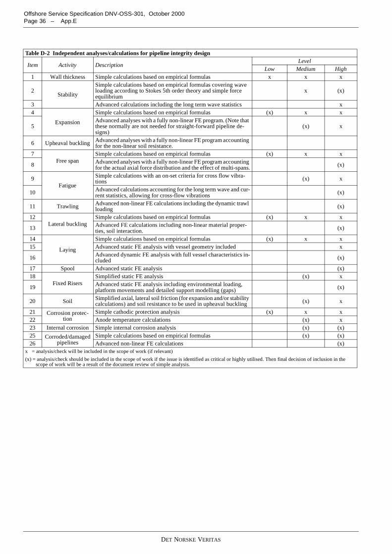
DET NORSKE VERITAS
Offshore Service Specification DNV-OSS-301, October 2000Page 36 – App.E
Table D-2 Independent analyses/calculations for pipeline integrity design
Item Activity DescriptionLevel
Low Medium High1 Wall thickness Simple calculations based on empirical formulas x x x
2Stability
Simple calculations based on empirical formulas covering waveloading according to Stokes 5th order theory and simple forceequilibrium
x (x)
3 Advanced calculations including the long term wave statistics x4
Expansion
Simple calculations based on empirical formulas (x) x x
5Advanced analyses with a fully non-linear FE program. (Note thatthese normally are not needed for straight-forward pipeline de-signs)
(x) x
6 Upheaval buckling Advanced analyses with a fully non-linear FE program accountingfor the non-linear soil resistance.
7Free span
Simple calculations based on empirical formulas (x) x x
8 Advanced analyses with a fully non-linear FE program accountingfor the actual axial force distribution and the effect of multi-spans. (x)
9Fatigue
Simple calculations with an on-set criteria for cross flow vibra-tions (x) x
10 Advanced calculations accounting for the long term wave and cur-rent statistics, allowing for cross-flow vibrations (x)
11 Trawling Advanced non-linear FE calculations including the dynamic trawlloading (x)
12Lateral buckling
Simple calculations based on empirical formulas (x) x x
13 Advanced FE calculations including non-linear material proper-ties, soil interaction. (x)
14
Laying
Simple calculations based on empirical formulas (x) x x15 Advanced static FE analysis with vessel geometry included x
16 Advanced dynamic FE analysis with full vessel characteristics in-cluded (x)
17 Spool Advanced static FE analysis (x)18
Fixed RisersSimplified static FE analysis (x) x
19 Advanced static FE analysis including environmental loading,platform movements and detailed support modelling (gaps) (x)
20 Soil Simplified axial, lateral soil friction (for expansion and/or stabilitycalculations) and soil resistance to be used in upheaval buckling (x) x
21 Corrosion protec-tion
Simple cathodic protection analysis (x) x x22 Anode temperature calculations (x) x23 Internal corrosion Simple internal corrosion analysis (x) (x)25 Corroded/damaged
pipelinesSimple calculations based on empirical formulas (x) (x)
26 Advanced non-linear FE calculations (x)x = analysis/check will be included in the scope of work (if relevant)
(x) = analysis/check should be included in the scope of work if the issue is identified as critical or highly utilised. Then final decision of inclusion in thescope of work will be a result of the document review of simple analysis.
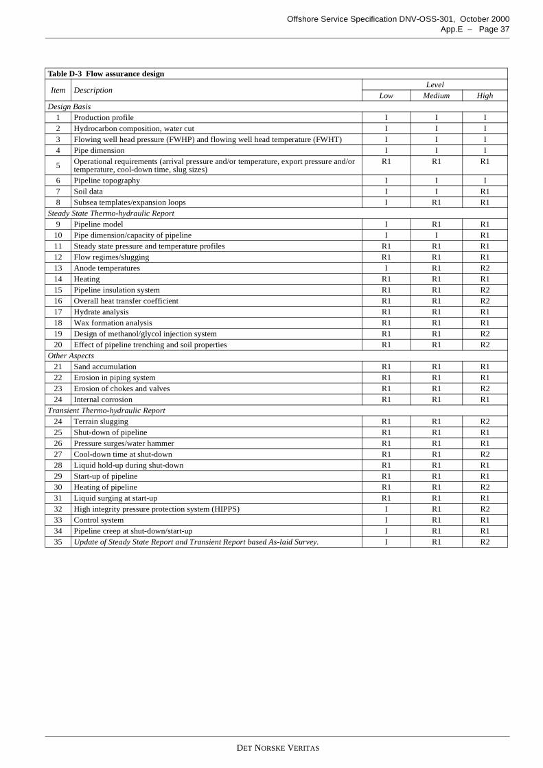
DET NORSKE VERITAS
Offshore Service Specification DNV-OSS-301, October 2000App.E – Page 37
Table D-3 Flow assurance design
Item DescriptionLevel
Low Medium HighDesign Basis
1 Production profile I I I2 Hydrocarbon composition, water cut I I I3 Flowing well head pressure (FWHP) and flowing well head temperature (FWHT) I I I4 Pipe dimension I I I
5 Operational requirements (arrival pressure and/or temperature, export pressure and/ortemperature, cool-down time, slug sizes)
R1 R1 R1
6 Pipeline topography I I I7 Soil data I I R18 Subsea templates/expansion loops I R1 R1
Steady State Thermo-hydraulic Report9 Pipeline model I R1 R1
10 Pipe dimension/capacity of pipeline I I R111 Steady state pressure and temperature profiles R1 R1 R112 Flow regimes/slugging R1 R1 R113 Anode temperatures I R1 R214 Heating R1 R1 R115 Pipeline insulation system R1 R1 R216 Overall heat transfer coefficient R1 R1 R217 Hydrate analysis R1 R1 R118 Wax formation analysis R1 R1 R119 Design of methanol/glycol injection system R1 R1 R220 Effect of pipeline trenching and soil properties R1 R1 R2
Other Aspects21 Sand accumulation R1 R1 R122 Erosion in piping system R1 R1 R123 Erosion of chokes and valves R1 R1 R224 Internal corrosion R1 R1 R1
Transient Thermo-hydraulic Report24 Terrain slugging R1 R1 R225 Shut-down of pipeline R1 R1 R126 Pressure surges/water hammer R1 R1 R127 Cool-down time at shut-down R1 R1 R228 Liquid hold-up during shut-down R1 R1 R129 Start-up of pipeline R1 R1 R130 Heating of pipeline R1 R1 R231 Liquid surging at start-up R1 R1 R132 High integrity pressure protection system (HIPPS) I R1 R233 Control system I R1 R134 Pipeline creep at shut-down/start-up I R1 R135 Update of Steady State Report and Transient Report based As-laid Survey. I R1 R2
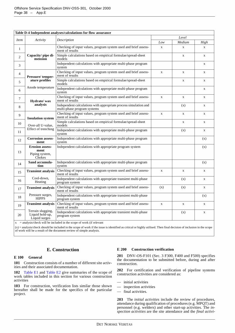
DET NORSKE VERITAS
Offshore Service Specification DNV-OSS-301, October 2000Page 38 – App.E
E. Construction
E 100 General101 Construction consists of a number of different site activ-ities and their associated documentation.
102 Table E1 and Table E2 give summaries of the scope ofwork tables included in this section for various constructionactivities
103 For construction, verification lists similar those shownhereafter shall be made for the specifics of the particularproject.
E 200 Construction verification
201 DNV-OS-F101 (Sec. 3 F300, F400 and F500) specifiesthe documentation to be submitted before, during and afterconstruction.
202 For certification and verification of pipeline systemsconstruction activities are considered as:
— initial activities— inspection activities— final activities.
203 The initial activities include the review of procedures,attendance during qualification of procedures (e.g. MPQT) andpersonnel (e.g. welders) and other start-up activities. The in-spection activities are the site attendance and the final activi-
Table D-4 Independent analyses/calculations for flow assurance
Item Activity DescriptionLevel
Low Medium High
1
Capacity/ pipe di-mension
Checking of input values, program system used and brief assess-ment of results
x x x
2 Simple calculations based on empirical formulae/spread-sheetmodels
x x
3 Independent calculations with appropriate multi-phase programsystem
x
4Pressure/ temper-
ature profiles
Anode temperature
Checking of input values, program system used and brief assess-ment of results
x x x
5 Simple calculations based on empirical formulae/spread-sheetmodels
x x
6 Independent calculations with appropriate multi-phase programsystem
x
7Hydrate/ wax
analysis
Checking of input values, program system used and brief assess-ment of results
x x x
8 Independent calculations with appropriate process simulation andmulti-phase program systems
(x) x
9Insulation system
Over-all U-value,Effect of trenching
Checking of input values, program system used and brief assess-ment of results
x x x
10 Simple calculations based on empirical formulae/spread-sheetmodels
x x
11 Independent calculations with appropriate multi-phase programsystem
(x) x
12 Corrosion assess-ment
Independent calculations with appropriate multi-phase programsystem
(x)
13
Erosion assess-ment
Piping system,Chokes
Independent calculations with appropriate program system (x)
14 Sand accumula-tion
Independent calculations with appropriate multi-phase programsystem
(x)
15 Transient analysis
Cool-down,Heating
Checking of input values, program system used and brief assess-ment of results
x x x
16 Independent calculations with appropriate transient multi-phaseprogram system
(x) x
17 Transient analysis
Pressure surges,HIPPS
Checking of input values, program system used and brief assess-ment of results
(x) (x) x
18 Independent calculations with appropriate transient multi-phaseprogram system
(x)
19 Transient analysis
Terrain slugging,Liquid hold-up,Liquid surges
Checking of input values, program system used and brief assess-ment of results
x x x
20Independent calculations with appropriate transient multi-phaseprogram system
(x) x
x = analysis/check will be included in the scope of work (if relevant
(x) = analysis/check should be included in the scope of work if the issue is identified as critical or highly utilised. Then final decision of inclusion in the scopeof work will be a result of the document review of simple analysis.
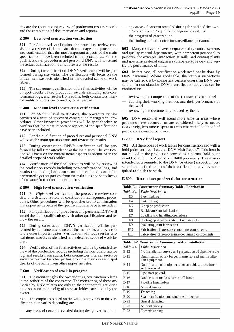
DET NORSKE VERITAS
Offshore Service Specification DNV-OSS-301, October 2000App.E – Page 39
ties are the (continuous) review of production results/recordsand the completion of documentation and reports.
E 300 Low level construction verification
301 For Low level verification, the procedure review con-sists of a review of the construction management proceduresand confirmation that the most important aspects of the mainspecifications have been included in the procedures. For thequalification of procedures and personnel DNV will not attendthe actual qualification, but will review the results.
302 During the construction, DNV’s verification will be per-formed during site visits. The verification will focus on thecritical items/aspects identified in the detailed scope of worktables.
303 The subsequent verification of the final activities will beby spot-checks of the production records including non-con-formance logs, and results from audits, both contractors inter-nal audits or audits performed by other parties.
E 400 Medium level construction verification
401 For Medium level verification, the procedure reviewconsists of a detailed review of construction management pro-cedures. Other important procedures will be spot checked toconfirm that the most important aspects of the specificationshave been included.
402 For the qualification of procedures and personnel DNVwill visit the main qualifications and review the results.
403 During construction, DNV’s verification will be per-formed by full time attendance at the main sites. The verifica-tion will focus on the critical items/aspects as identified in thedetailed scope of work tables.
404 Verification of the final activities will be by review ofthe production records including non-conformance logs, andresults from audits, both contractor’s internal audits or auditsperformed by other parties, from the main sites and spot checksof the same from other important sites.
E 500 High level construction verification
501 For High level verification, the procedure review con-sists of a detailed review of construction management proce-dures. Other procedures will be spot checked to confirmationthat important aspects of the specifications have been included.
502 For qualification of procedures and personnel DNV willattend the main qualifications, visit other qualifications and re-view the results
503 During construction, DNV’s verification will be per-formed by full time attendance at the main sites and by visitsto the other important sites. Verification will focus on the crit-ical items/aspects as identified in the detailed scope of work ta-bles.
504 Verification of the final activities will be by detailed re-view of the production records including the non-conformancelog, and results from audits, both contractors internal audits oraudits performed by other parties, from the main sites and spotchecks of the same from other important sites.
E 600 Verification of work in progress
601 The monitoring by the owner during construction relatesto the activities of the contractor. The monitoring of these ac-tivities by DNV relates not only to the contractor’s activitiesbut also to the monitoring of these activities carried out by theowner.
602 The emphasis placed on the various activities in the ver-ification plan varies depending on:
— any areas of concern revealed during design verification
— any areas of concern revealed during the audit of the own-er’s or contractor’s quality management systems
— the progress of construction— the findings of the contractor surveillance personnel.
603 Many contractors have adequate quality control systemsand quality control departments, with competent personnel toperform, for example, inspection at mills and coating plantsand specialist material engineers competent to review and ver-ify the performance of mills.
604 In that case, all certification work need not be done byDNV personnel. Where applicable, the various inspectionsmay be carried out by competent persons other than DNV per-sonnel. In that situation DNV’s certification activities can beconfined to:
— reviewing the competence of the contractor’s personnel— auditing their working methods and their performance of
that work— reviewing the documents produced by them.
605 DNV personnel will spend more time in areas whereproblems have occurred, or are considered likely to occur.Conversely, less time is spent in areas where the likelihood ofproblems is considered lower.
E 700 DNV final report
701 All the scopes of work tables for construction end with ahold point entitled “Issue of DNV Visit Report”. This item isnot related to the production process as a normal hold pointwould be, reference Appendix E B400 previously. This item isintended as a reminder to the DNV (or others) inspection per-sonnel that a final report of their verification activities is re-quired to finish the work.
E 800 Detailed scope of work for construction
Table E-1 Construction Summary Table - FabricationTable No. Table Description
E3 Steel makingE4 Plate rollingE5 Linepipe productionE6 Buckle arrestor fabricationE7 Loading and handling operationsE8 Coating application (internal or external)E9 Insulating joint fabricationE10 Fabrication of pressure containing componentsE11 Fabrication of non-pressure containing components
Table E-2 Construction Summary Table - InstallationTable No. Table DescriptionE-12 Pre-installation survey and preparation of pipeline routeE-13 Qualification of lay barge, marine spread and installa-
tion equipmentE-14 Qualification of equipment, consumables, procedures
and personnelE-15 Pipe storage yardE-16 Double jointing (onshore or offshore)E-17 Pipeline installationE-18 As-laid surveyE-19 TrenchingE-20 Span rectification and pipeline protectionE-21 Gravel dumpingE-22 As-built surveyE-23 Commissioning
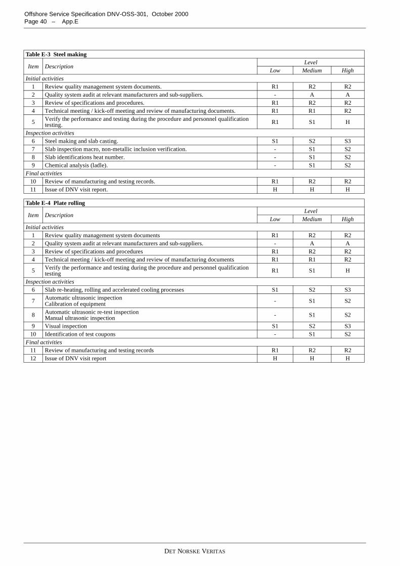
DET NORSKE VERITAS
Offshore Service Specification DNV-OSS-301, October 2000Page 40 – App.E
Table E-3 Steel making
Item DescriptionLevel
Low Medium HighInitial activities
1 Review quality management system documents. R1 R2 R22 Quality system audit at relevant manufacturers and sub-suppliers. - A A3 Review of specifications and procedures. R1 R2 R24 Technical meeting / kick-off meeting and review of manufacturing documents. R1 R1 R2
5 Verify the performance and testing during the procedure and personnel qualificationtesting. R1 S1 H
Inspection activities6 Steel making and slab casting. S1 S2 S37 Slab inspection macro, non-metallic inclusion verification. - S1 S28 Slab identifications heat number. - S1 S29 Chemical analysis (ladle). - S1 S2
Final activities10 Review of manufacturing and testing records. R1 R2 R211 Issue of DNV visit report. H H H
Table E-4 Plate rolling
Item DescriptionLevel
Low Medium HighInitial activities
1 Review quality management system documents R1 R2 R22 Quality system audit at relevant manufacturers and sub-suppliers. - A A3 Review of specifications and procedures R1 R2 R24 Technical meeting / kick-off meeting and review of manufacturing documents R1 R1 R2
5 Verify the performance and testing during the procedure and personnel qualificationtesting R1 S1 H
Inspection activities6 Slab re-heating, rolling and accelerated cooling processes S1 S2 S3
7 Automatic ultrasonic inspectionCalibration of equipment - S1 S2
8 Automatic ultrasonic re-test inspectionManual ultrasonic inspection - S1 S2
9 Visual inspection S1 S2 S310 Identification of test coupons - S1 S2
Final activities11 Review of manufacturing and testing records R1 R2 R212 Issue of DNV visit report H H H
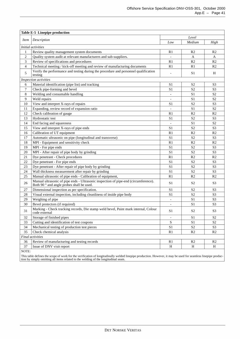
DET NORSKE VERITAS
Offshore Service Specification DNV-OSS-301, October 2000App.E – Page 41
Table E-5 Linepipe production
Item DescriptionLevel
Low Medium HighInitial activities
1 Review quality management system documents R1 R2 R22 Quality system audit at relevant manufacturers and sub-suppliers. - A A3 Review of specifications and procedures R1 R2 R24 Technical meeting / kick-off meeting and review of manufacturing documents R1 R1 R2
5 Verify the performance and testing during the procedure and personnel qualificationtesting - S1 H
Inspection activities6 Material identification (pipe list) and tracking S1 S2 S37 Check pipe-forming and bevel S1 S2 S38 Welding and consumable handling - S1 S29 Weld repairs - S1 S2
10 View and interpret X-rays of repairs S1 S2 S311 Expanding, review record of expansion ratio - S1 S212 Check calibration of gauge R1 R2 R213 Hydrostatic test S1 S2 S314 End facing and squareness - S1 S215 View and interpret X-rays of pipe ends S1 S2 S316 Calibration of UT equipment R1 R2 R217 Automatic ultrasonic on pipe (longitudinal and transverse) S1 S2 S318 MPI - Equipment and sensitivity check R1 R2 R219 MPI - For pipe ends S1 S2 S320 MPI - After repair of pipe body by grinding S1 S2 S321 Dye penetrant - Check procedures R1 R2 R222 Dye penetrant - For pipe ends S1 S2 S323 Dye penetrant - After repair of pipe body by grinding S1 S2 S324 Wall thickness measurement after repair by grinding S1 S2 S325 Manual ultrasonic of pipe ends - Calibration of equipment, R1 R2 R2
26 Manual ultrasonic of pipe ends - Ultrasonic inspection of pipe-end (circumference).Both 90 ° and angle probes shall be used. S1 S2 S3
27 Dimensional inspection as per specification. S1 S2 S328 Visual external inspection, including cleanliness of inside pipe body S1 S2 S329 Weighing of pipe - S1 S330 Bevel protectors (if required) - S1 S3
31 Marking - Check tracking records, Die stamp weld bevel, Paint mark internal, Colourcode external S1 S2 S3
32 Storage of finished pipes - S1 S233 Cutting and identification of test coupons S S1 S234 Mechanical testing of production test pieces S1 S2 S335 Check chemical analysis R1 R2 R2
Final activities36 Review of manufacturing and testing records R1 R2 R237 Issue of DNV visit report H H H
NOTE:
This table defines the scope of work for the verification of longitudinally welded linepipe production. However, it may be used for seamless linepipe produc-tion by simply omitting all items related to the welding of the longitudinal seam.

DET NORSKE VERITAS
Offshore Service Specification DNV-OSS-301, October 2000Page 42 – App.E
Table E-6 Buckle arrestor fabrication
Item DescriptionLevel
Low Medium HighInitial activities
1 Review quality management system documents R1 R2 R22 Quality system audit at relevant manufacturers and sub-suppliers. - A A3 Review of specifications and procedures R1 R2 R24 Technical meeting / kick-off meeting and review of manufacturing documents R1 R1 R2
5 Verify the performance and testing during the procedure and personnel qualificationtesting R1 S1 H
Inspection activities6 Material identification (Pipe list) R1 R2 R27 Check pipe- forming (forging), heat treatment (Q/T) and machining S1 S2 S38 Welding and consumable handling - S1 S29 NDT S1 S2 S3
10 Check calibration of gauge R1 R2 R211 Hydrostatic test S1 S2 S312 Dimensional inspection as per specification. S1 S2 S313 Visual external inspection, including cleanliness of inside pipe body S1 S2 S314 Weighing of buckle arrestors - S1 S215 Bevel protectors (if required) - S1 S2
16 Marking - Check tracking records, Die stamp weld bevel, Paint mark internal, Colourcode external - S1 S2
17 Storage of finished buckle arrestors - S1 S218 Removal and identification of test coupons S1 S2 S319 Mechanical testing of production test pieces S1 S2 S320 Check chemical analysis R1 R2 R2
Final activities21 Review of Fabrication Records R1 R2 R222 Review of Testing Records R1 R2 R223 Issue of DNV Visit Report H H H
Table E-7 Loading and handling operations
Item DescriptionLevel
Low Medium HighInitial activities
1 Review quality management system documents R1 R2 R22 Quality system audit at relevant manufacturers and sub-suppliers. - A A3 Review of specifications and procedures R1 R2 R2
Inspection activities4 Loading and handling operations at manufacturer - S1 S25 Loading operations in port - S1 S2
Final activities6 Review of manufacturing and testing records R1 R2 R27 Issue of DNV visit report H H H
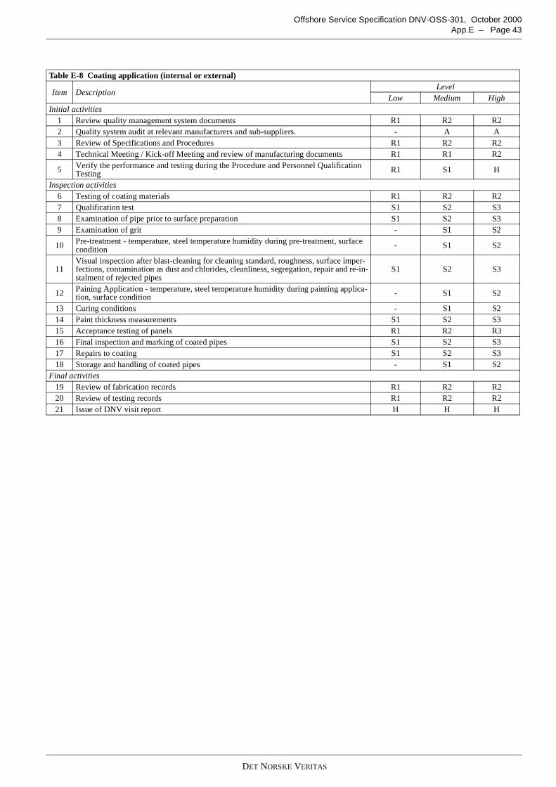
DET NORSKE VERITAS
Offshore Service Specification DNV-OSS-301, October 2000App.E – Page 43
Table E-8 Coating application (internal or external)
Item DescriptionLevel
Low Medium HighInitial activities
1 Review quality management system documents R1 R2 R22 Quality system audit at relevant manufacturers and sub-suppliers. - A A3 Review of Specifications and Procedures R1 R2 R24 Technical Meeting / Kick-off Meeting and review of manufacturing documents R1 R1 R2
5 Verify the performance and testing during the Procedure and Personnel QualificationTesting R1 S1 H
Inspection activities6 Testing of coating materials R1 R2 R27 Qualification test S1 S2 S38 Examination of pipe prior to surface preparation S1 S2 S39 Examination of grit - S1 S2
10 Pre-treatment - temperature, steel temperature humidity during pre-treatment, surfacecondition - S1 S2
11Visual inspection after blast-cleaning for cleaning standard, roughness, surface imper-fections, contamination as dust and chlorides, cleanliness, segregation, repair and re-in-stalment of rejected pipes
S1 S2 S3
12 Paining Application - temperature, steel temperature humidity during painting applica-tion, surface condition - S1 S2
13 Curing conditions - S1 S214 Paint thickness measurements S1 S2 S315 Acceptance testing of panels R1 R2 R316 Final inspection and marking of coated pipes S1 S2 S317 Repairs to coating S1 S2 S318 Storage and handling of coated pipes - S1 S2
Final activities19 Review of fabrication records R1 R2 R220 Review of testing records R1 R2 R221 Issue of DNV visit report H H H
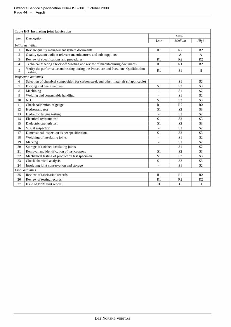
DET NORSKE VERITAS
Offshore Service Specification DNV-OSS-301, October 2000Page 44 – App.E
Table E-9 Insulating joint fabrication
Item DescriptionLevel
Low Medium HighInitial activities
1 Review quality management system documents R1 R2 R22 Quality system audit at relevant manufacturers and sub-suppliers. - A A3 Review of specifications and procedures R1 R2 R24 Technical Meeting / Kick-off Meeting and review of manufacturing documents R1 R1 R2
5 Verify the performance and testing during the Procedure and Personnel QualificationTesting R1 S1 H
Inspection activities6 Selection of chemical composition for carbon steel, and other materials (if applicable) S1 S27 Forging and heat treatment S1 S2 S38 Machining - S1 S29 Welding and consumable handling - S1 S2
10 NDT S1 S2 S311 Check calibration of gauge R1 R2 R212 Hydrostatic test S1 S2 S313 Hydraulic fatigue testing - S1 S214 Electrical resistant test S1 S2 S315 Dielectric strength test S1 S2 S316 Visual inspection - S1 S217 Dimensional inspection as per specification. S1 S2 S318 Weighing of insulating joints - S1 S219 Marking - S1 S220 Storage of finished insulating joints - S1 S221 Removal and identification of test coupons S1 S2 S322 Mechanical testing of production test specimen S1 S2 S323 Check chemical analysis S1 S2 S324 Insulating joint conservation and storage - S1 S2
Final activities25 Review of fabrication records R1 R2 R226 Review of testing records R1 R2 R227 Issue of DNV visit report H H H

DET NORSKE VERITAS
Offshore Service Specification DNV-OSS-301, October 2000App.E – Page 45
Table E-10 Fabrication of pressure containing components
Item DescriptionLevel
Low Medium HighInitial activities
1 Review quality management system documents R1 R2 R22 Quality system audit at relevant manufacturers and sub-suppliers. - A A3 Review of specifications and procedures R1 R2 R24 Technical meeting / kick-off meeting and review of manufacturing documents R1 R1 R2
5 Verify the performance and testing during the procedure and personnel qualificationTesting R1 S1 H
Inspection activities6 Material identification (Material certificate) S1 S2 S37 Check pipe- forming (forging), heat treatment (Q/T) and machining S1 S2 S38 Welding and consumable handling - S1 S29 NDT S1 S2 S3
10 Check calibration of gauge R1 R2 R211 Hydrostatic test S1 S2 S312 Dimensional inspection as per specification. S1 S2 S313 Visual external inspection, including cleanliness of inside pipe body S1 S2 S314 Weighing of final product - S1 S215 Bevel protectors (if required) - S1 S2
16 Marking - Check tracking records, Dye stamp weld bevel, Paint mark internal, colourcode external etc. - S1 S2
17 Storage of final product - S1 S218 Cutting and identification of test coupons S1 S2 S319 Mechanical testing of production test specimen S1 S2 S320 Check chemical analysis S1 S2 S3
Final activities21 Review of fabrication records R1 R2 R222 Review of testing records R1 R2 R223 Issue of DNV visit report H H H
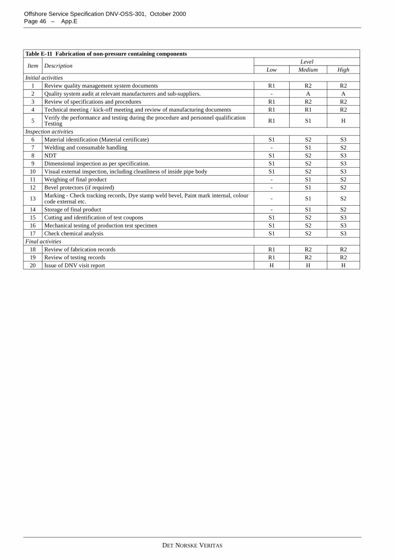
DET NORSKE VERITAS
Offshore Service Specification DNV-OSS-301, October 2000Page 46 – App.E
Table E-11 Fabrication of non-pressure containing components
Item DescriptionLevel
Low Medium HighInitial activities
1 Review quality management system documents R1 R2 R22 Quality system audit at relevant manufacturers and sub-suppliers. - A A3 Review of specifications and procedures R1 R2 R24 Technical meeting / kick-off meeting and review of manufacturing documents R1 R1 R2
5 Verify the performance and testing during the procedure and personnel qualificationTesting R1 S1 H
Inspection activities6 Material identification (Material certificate) S1 S2 S37 Welding and consumable handling - S1 S28 NDT S1 S2 S39 Dimensional inspection as per specification. S1 S2 S3
10 Visual external inspection, including cleanliness of inside pipe body S1 S2 S311 Weighing of final product - S1 S212 Bevel protectors (if required) - S1 S2
13 Marking - Check tracking records, Dye stamp weld bevel, Paint mark internal, colourcode external etc. - S1 S2
14 Storage of final product - S1 S215 Cutting and identification of test coupons S1 S2 S316 Mechanical testing of production test specimen S1 S2 S317 Check chemical analysis S1 S2 S3
Final activities18 Review of fabrication records R1 R2 R219 Review of testing records R1 R2 R220 Issue of DNV visit report H H H
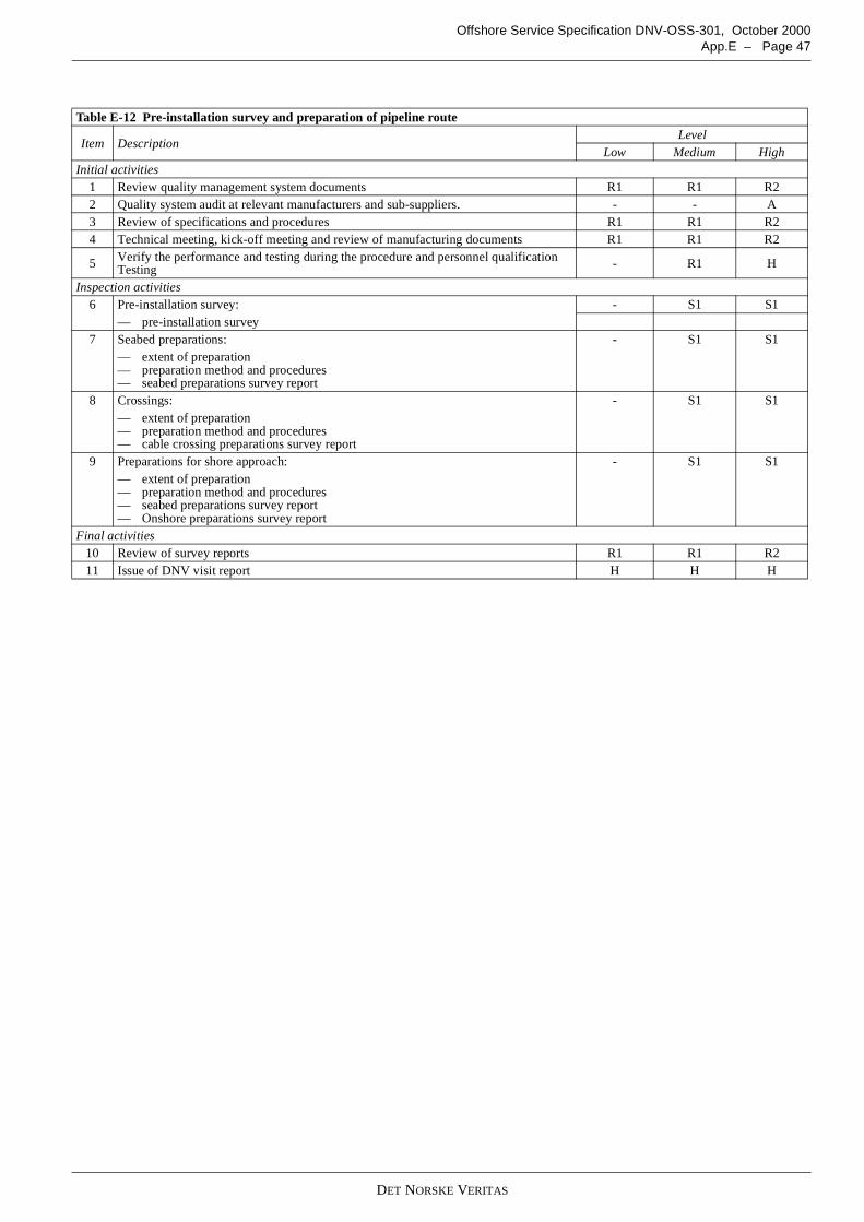
DET NORSKE VERITAS
Offshore Service Specification DNV-OSS-301, October 2000App.E – Page 47
Table E-12 Pre-installation survey and preparation of pipeline route
Item DescriptionLevel
Low Medium HighInitial activities
1 Review quality management system documents R1 R1 R22 Quality system audit at relevant manufacturers and sub-suppliers. - - A3 Review of specifications and procedures R1 R1 R24 Technical meeting, kick-off meeting and review of manufacturing documents R1 R1 R2
5 Verify the performance and testing during the procedure and personnel qualificationTesting - R1 H
Inspection activities6 Pre-installation survey: - S1 S1
— pre-installation survey7 Seabed preparations: - S1 S1
— extent of preparation— preparation method and procedures— seabed preparations survey report
8 Crossings: - S1 S1— extent of preparation— preparation method and procedures— cable crossing preparations survey report
9 Preparations for shore approach: - S1 S1— extent of preparation— preparation method and procedures— seabed preparations survey report— Onshore preparations survey report
Final activities10 Review of survey reports R1 R1 R211 Issue of DNV visit report H H H
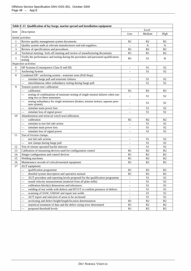
DET NORSKE VERITAS
Offshore Service Specification DNV-OSS-301, October 2000Page 48 – App.E
Table E-13 Qualification of lay barge, marine spread and installation equipment
Item DescriptionLevel
Low Medium HighInitial activities
1 Review quality management system documents R1 R2 R22 Quality system audit at relevant manufacturers and sub-suppliers. - A A3 Review of specifications and procedures R1 R2 R24 Technical meeting / kick-off meeting and review of manufacturing documents R1 R1 R2
5 Verify the performance and testing during the procedure and personnel qualificationtesting R1 S1 H
Inspection activities6 DP Systems (Consequence Class II and III) - S1 S27 Anchoring System - S1 S28 Combined DP / anchoring system - tensioner tests (Pull-Stop):
— simulate barge pull and tensioner failures - S1 S2— miscellaneous other redundancy testing during barge pull - S1 S2
9 Tension system test/ calibration:— calibration R1 R2 R2— testing of combinations of tensioner testing of single tension failures when run-
ning two or three tensioners - S1 S2
— testing redundancy for single tensioners (brakes, tension motors, squeeze pres-sure system) - S1 S2
— simulate main power loss - S1 S2— simulate loss of signal power - S1 S2
10 Abandonment and retrieval winch test/calibration:— calibration R1 R2 R2— simulate to test fail safe action - S1 S2— simulate main power loss - S1 S2— simulate loss of signal power - S1 S2
11 Test of friction clamps:— test fail safe actions - S1 S2— test clamps during barge pull - S1 S2
12 Test of remote operated buckle detector - S1 S213 Calibration of measuring devices used for configuration control R1 R2 R214 Stinger configuration and control devices R1 R2 R215 Welding machines R1 R2 R216 Maintenance records of critical/essential equipment R1 R2 R217 AUT equipment:
— qualification programme R1 R2 R2— detailed system description and operation manual R1 R2 R2— AUT procedure and reporting levels proposed for the qualification programme - S1 S2— sound velocity measurements (material from all plate mills) - S1 S2— calibration block(s) dimensions and tolerances - S1 S2— welding of test welds with defects and RT/UT to confirm presence of defects - S1 S2— scanning of SAW, GMAW and repair test welds - S1 S2— AUT report and selection of areas to be sectioned - S1 S2— sectioning and defect height/length/location determination R1 R2 R2— statistical treatment of data and the defect sizing error determined R1 R2 R2— proposed threshold levels R1 R2 R2
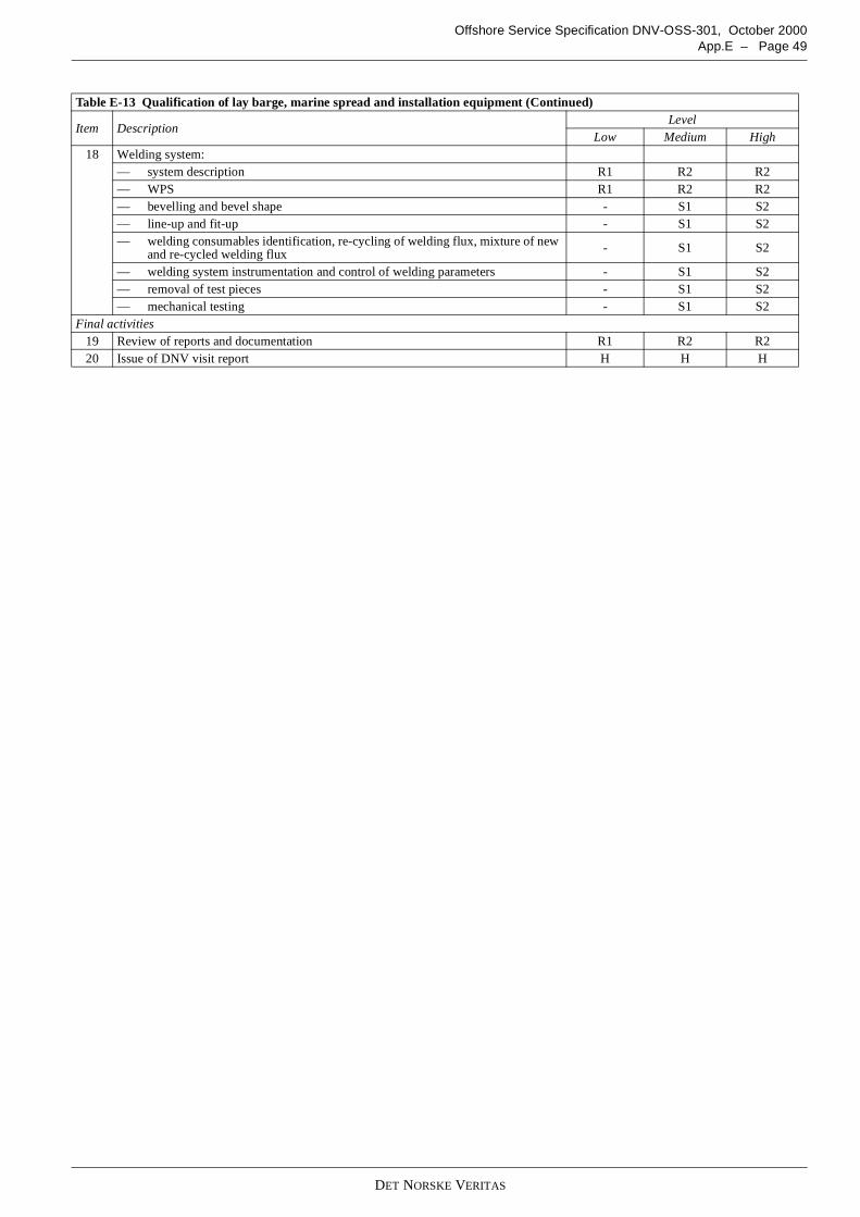
DET NORSKE VERITAS
Offshore Service Specification DNV-OSS-301, October 2000App.E – Page 49
18 Welding system:— system description R1 R2 R2— WPS R1 R2 R2— bevelling and bevel shape - S1 S2— line-up and fit-up - S1 S2— welding consumables identification, re-cycling of welding flux, mixture of new
and re-cycled welding flux - S1 S2
— welding system instrumentation and control of welding parameters - S1 S2— removal of test pieces - S1 S2— mechanical testing - S1 S2
Final activities19 Review of reports and documentation R1 R2 R220 Issue of DNV visit report H H H
Table E-13 Qualification of lay barge, marine spread and installation equipment (Continued)
Item DescriptionLevel
Low Medium High
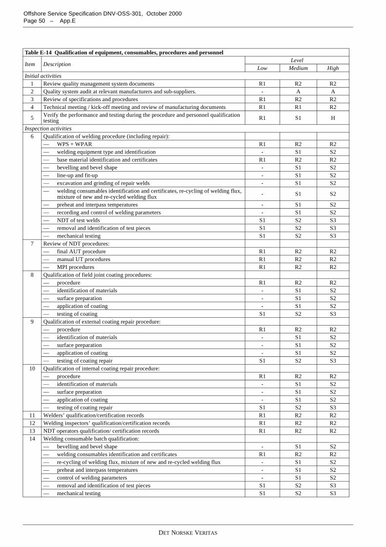
DET NORSKE VERITAS
Offshore Service Specification DNV-OSS-301, October 2000Page 50 – App.E
Table E-14 Qualification of equipment, consumables, procedures and personnel
Item DescriptionLevel
Low Medium HighInitial activities
1 Review quality management system documents R1 R2 R22 Quality system audit at relevant manufacturers and sub-suppliers. - A A3 Review of specifications and procedures R1 R2 R24 Technical meeting / kick-off meeting and review of manufacturing documents R1 R1 R2
5 Verify the performance and testing during the procedure and personnel qualificationtesting R1 S1 H
Inspection activities6 Qualification of welding procedure (including repair):
— WPS + WPAR R1 R2 R2— welding equipment type and identification - S1 S2— base material identification and certificates R1 R2 R2— bevelling and bevel shape - S1 S2— line-up and fit-up - S1 S2— excavation and grinding of repair welds - S1 S2— welding consumables identification and certificates, re-cycling of welding flux,
mixture of new and re-cycled welding flux - S1 S2
— preheat and interpass temperatures - S1 S2— recording and control of welding parameters - S1 S2— NDT of test welds S1 S2 S3— removal and identification of test pieces S1 S2 S3— mechanical testing S1 S2 S3
7 Review of NDT procedures:— final AUT procedure R1 R2 R2— manual UT procedures R1 R2 R2— MPI procedures R1 R2 R2
8 Qualification of field joint coating procedures:— procedure R1 R2 R2— identification of materials - S1 S2— surface preparation - S1 S2— application of coating - S1 S2— testing of coating S1 S2 S3
9 Qualification of external coating repair procedure:— procedure R1 R2 R2— identification of materials - S1 S2— surface preparation - S1 S2— application of coating - S1 S2— testing of coating repair S1 S2 S3
10 Qualification of internal coating repair procedure:— procedure R1 R2 R2— identification of materials - S1 S2— surface preparation - S1 S2— application of coating - S1 S2— testing of coating repair S1 S2 S3
11 Welders’ qualification/certification records R1 R2 R212 Welding inspectors’ qualification/certification records R1 R2 R213 NDT operators qualification/ certification records R1 R2 R214 Welding consumable batch qualification:
— bevelling and bevel shape - S1 S2— welding consumables identification and certificates R1 R2 R2— re-cycling of welding flux, mixture of new and re-cycled welding flux - S1 S2— preheat and interpass temperatures - S1 S2— control of welding parameters - S1 S2— removal and identification of test pieces S1 S2 S3— mechanical testing S1 S2 S3
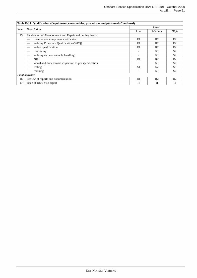
DET NORSKE VERITAS
Offshore Service Specification DNV-OSS-301, October 2000App.E – Page 51
15 Fabrication of Abandonment and Repair and pulling heads:— material and component certificates R1 R2 R2— welding Procedure Qualification (WPQ) R1 R2 R2— welder qualification R1 R2 R2— machining - S1 S2— welding and consumable handling - S1 S2— NDT R1 R2 R2— visual and dimensional inspection as per specification - S1 S2— testing S1 S2 S3— marking - S1 S2
Final activities16 Review of reports and documentation R1 R2 R217 Issue of DNV visit report H H H
Table E-14 Qualification of equipment, consumables, procedures and personnel (Continued)
Item DescriptionLevel
Low Medium High
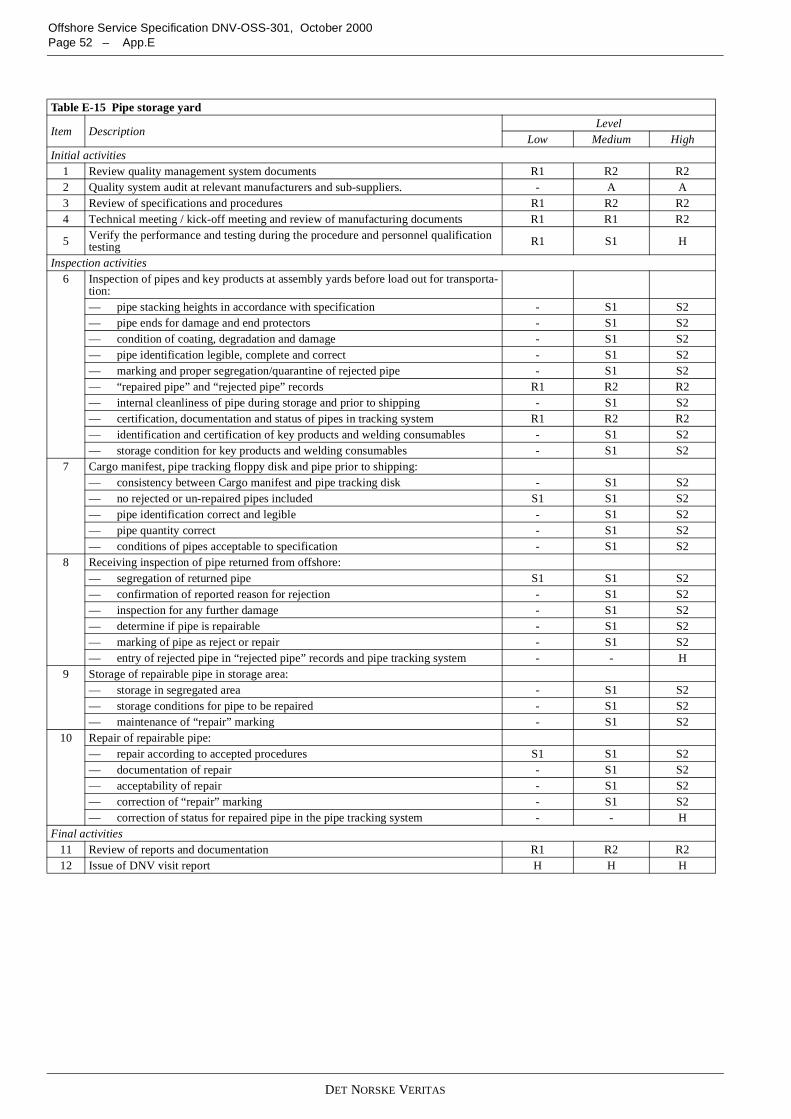
DET NORSKE VERITAS
Offshore Service Specification DNV-OSS-301, October 2000Page 52 – App.E
Table E-15 Pipe storage yard
Item DescriptionLevel
Low Medium HighInitial activities
1 Review quality management system documents R1 R2 R22 Quality system audit at relevant manufacturers and sub-suppliers. - A A3 Review of specifications and procedures R1 R2 R24 Technical meeting / kick-off meeting and review of manufacturing documents R1 R1 R2
5 Verify the performance and testing during the procedure and personnel qualificationtesting R1 S1 H
Inspection activities6 Inspection of pipes and key products at assembly yards before load out for transporta-
tion:— pipe stacking heights in accordance with specification - S1 S2— pipe ends for damage and end protectors - S1 S2— condition of coating, degradation and damage - S1 S2— pipe identification legible, complete and correct - S1 S2— marking and proper segregation/quarantine of rejected pipe - S1 S2— “repaired pipe” and “rejected pipe” records R1 R2 R2— internal cleanliness of pipe during storage and prior to shipping - S1 S2— certification, documentation and status of pipes in tracking system R1 R2 R2— identification and certification of key products and welding consumables - S1 S2— storage condition for key products and welding consumables - S1 S2
7 Cargo manifest, pipe tracking floppy disk and pipe prior to shipping:— consistency between Cargo manifest and pipe tracking disk - S1 S2— no rejected or un-repaired pipes included S1 S1 S2— pipe identification correct and legible - S1 S2— pipe quantity correct - S1 S2— conditions of pipes acceptable to specification - S1 S2
8 Receiving inspection of pipe returned from offshore:— segregation of returned pipe S1 S1 S2— confirmation of reported reason for rejection - S1 S2— inspection for any further damage - S1 S2— determine if pipe is repairable - S1 S2— marking of pipe as reject or repair - S1 S2— entry of rejected pipe in “rejected pipe” records and pipe tracking system - - H
9 Storage of repairable pipe in storage area:— storage in segregated area - S1 S2— storage conditions for pipe to be repaired - S1 S2— maintenance of “repair” marking - S1 S2
10 Repair of repairable pipe:— repair according to accepted procedures S1 S1 S2— documentation of repair - S1 S2— acceptability of repair - S1 S2— correction of “repair” marking - S1 S2— correction of status for repaired pipe in the pipe tracking system - - H
Final activities11 Review of reports and documentation R1 R2 R212 Issue of DNV visit report H H H
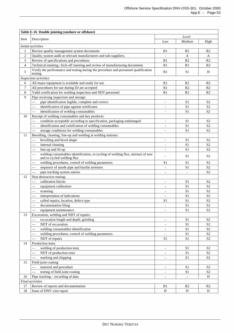
DET NORSKE VERITAS
Offshore Service Specification DNV-OSS-301, October 2000App.E – Page 53
Table E-16 Double jointing (onshore or offshore)
Item DescriptionLevel
Low Medium HighInitial activities
1 Review quality management system documents R1 R2 R22 Quality system audit at relevant manufacturers and sub-suppliers. - A A3 Review of specifications and procedures R1 R2 R24 Technical meeting / kick-off meeting and review of manufacturing documents R1 R1 R2
5 Verify the performance and testing during the procedure and personnel qualificationtesting R1 S1 H
Inspection activities6 All major equipment is available and ready for use R1 R2 R27 All procedures for use during DJ are accepted R1 R2 R28 Valid certification for welding inspection and NDT personnel R1 R2 R29 Pipe receiving inspection and storage:
— pipe identification legible, complete and correct - S1 S2— identification of pipe against certificates - S1 S2— identification of welding consumables - S1 S2
10 Receipt of welding consumables and key products:— condition acceptable according to specification, packaging undamaged - S1 S2— identification and certification of welding consumables - S1 S2— storage conditions for welding consumables - S1 S2
11 Bevelling, cleaning, line-up and welding at welding stations:— bevelling and bevel shape - S1 S2— internal cleaning - S1 S2— line-up and fit-up - S1 S2— welding consumables identification, re-cycling of welding flux, mixture of new
and re-cycled welding flux - S1 S2
— welding procedures, control of welding parameters S1 S1 S2— sequence of anode pipe and buckle arrestors - S1 S2— pipe tracking system entries - - S2
12 Non destructive testing:— calibration blocks - S1 S2— equipment calibration - S1 S2— scanning - S1 S2— interpretation of indications - S1 S2— called repairs, location, defect type S1 S1 S2— documentation filing - S1 S2— equipment maintenance - S1 S2
13 Excavation, welding and NDT of repairs:— excavation length and depth, grinding - S1 S2— NDT of excavation - S1 S2— welding consumables identification - S1 S2— welding procedures, control of welding parameters - S1 S2— NDT of repairs S1 S1 S2
14 Production tests:— welding of production tests - S1 S2— NDT of production tests - S1 S2— marking and shipping - S1 S2
15 Field joint coating:— material and procedure - S1 S2— testing of field joint coating - S1 S2
16 Pipe tracking – recording of data - - HFinal activities
17 Review of reports and documentation R1 R2 R218 Issue of DNV visit report H H H
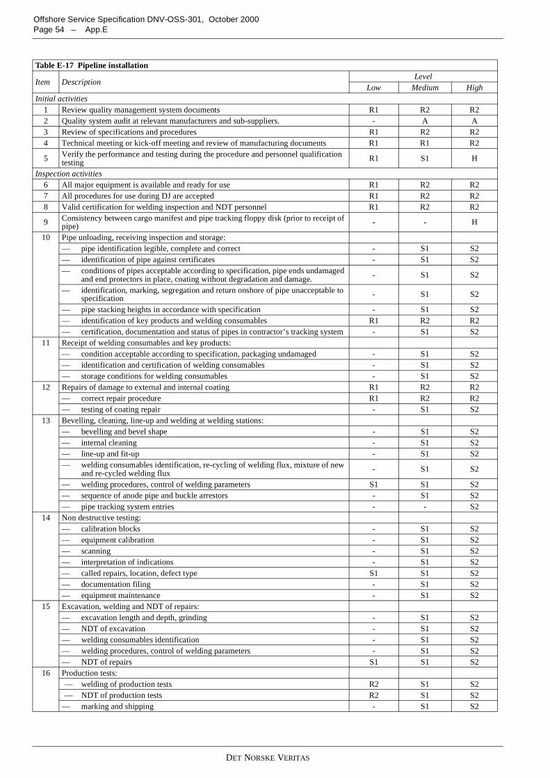
DET NORSKE VERITAS
Offshore Service Specification DNV-OSS-301, October 2000Page 54 – App.E
Table E-17 Pipeline installation
Item DescriptionLevel
Low Medium HighInitial activities
1 Review quality management system documents R1 R2 R22 Quality system audit at relevant manufacturers and sub-suppliers. - A A3 Review of specifications and procedures R1 R2 R24 Technical meeting or kick-off meeting and review of manufacturing documents R1 R1 R2
5 Verify the performance and testing during the procedure and personnel qualificationtesting R1 S1 H
Inspection activities6 All major equipment is available and ready for use R1 R2 R27 All procedures for use during DJ are accepted R1 R2 R28 Valid certification for welding inspection and NDT personnel R1 R2 R2
9 Consistency between cargo manifest and pipe tracking floppy disk (prior to receipt ofpipe) - - H
10 Pipe unloading, receiving inspection and storage:— pipe identification legible, complete and correct - S1 S2— identification of pipe against certificates - S1 S2— conditions of pipes acceptable according to specification, pipe ends undamaged
and end protectors in place, coating without degradation and damage. - S1 S2
— identification, marking, segregation and return onshore of pipe unacceptable tospecification - S1 S2
— pipe stacking heights in accordance with specification - S1 S2— identification of key products and welding consumables R1 R2 R2— certification, documentation and status of pipes in contractor’s tracking system - S1 S2
11 Receipt of welding consumables and key products:— condition acceptable according to specification, packaging undamaged - S1 S2— identification and certification of welding consumables - S1 S2— storage conditions for welding consumables - S1 S2
12 Repairs of damage to external and internal coating R1 R2 R2— correct repair procedure R1 R2 R2— testing of coating repair - S1 S2
13 Bevelling, cleaning, line-up and welding at welding stations:— bevelling and bevel shape - S1 S2— internal cleaning - S1 S2— line-up and fit-up - S1 S2— welding consumables identification, re-cycling of welding flux, mixture of new
and re-cycled welding flux - S1 S2
— welding procedures, control of welding parameters S1 S1 S2— sequence of anode pipe and buckle arrestors - S1 S2— pipe tracking system entries - - S2
14 Non destructive testing:— calibration blocks - S1 S2— equipment calibration - S1 S2— scanning - S1 S2— interpretation of indications - S1 S2— called repairs, location, defect type S1 S1 S2— documentation filing - S1 S2— equipment maintenance - S1 S2
15 Excavation, welding and NDT of repairs:— excavation length and depth, grinding - S1 S2— NDT of excavation - S1 S2— welding consumables identification - S1 S2— welding procedures, control of welding parameters - S1 S2— NDT of repairs S1 S1 S2
16 Production tests:— welding of production tests R2 S1 S2— NDT of production tests R2 S1 S2
— marking and shipping - S1 S2
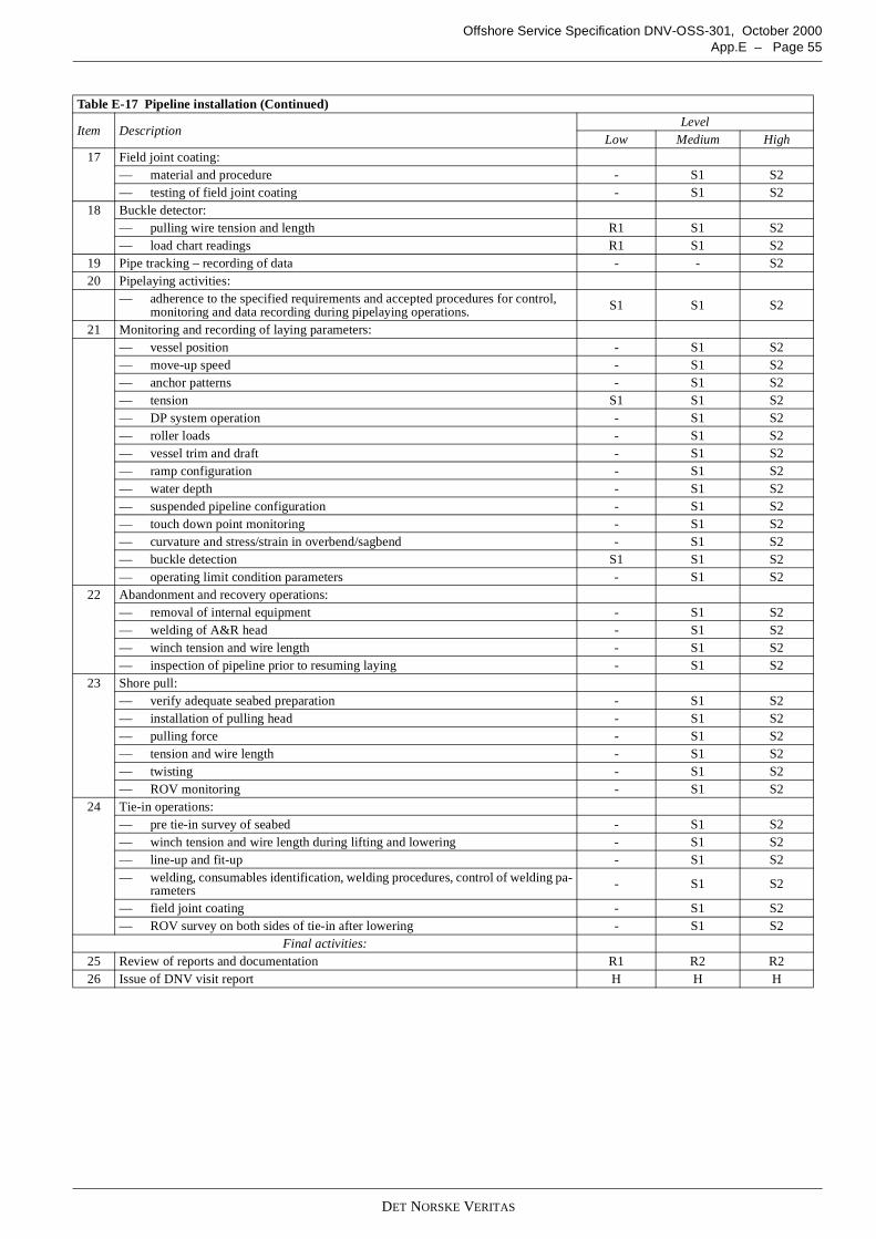
DET NORSKE VERITAS
Offshore Service Specification DNV-OSS-301, October 2000App.E – Page 55
17 Field joint coating:— material and procedure - S1 S2— testing of field joint coating - S1 S2
18 Buckle detector:— pulling wire tension and length R1 S1 S2— load chart readings R1 S1 S2
19 Pipe tracking – recording of data - - S220 Pipelaying activities:
— adherence to the specified requirements and accepted procedures for control,monitoring and data recording during pipelaying operations. S1 S1 S2
21 Monitoring and recording of laying parameters:— vessel position - S1 S2— move-up speed - S1 S2— anchor patterns - S1 S2— tension S1 S1 S2— DP system operation - S1 S2— roller loads - S1 S2— vessel trim and draft - S1 S2— ramp configuration - S1 S2— water depth - S1 S2— suspended pipeline configuration - S1 S2— touch down point monitoring - S1 S2— curvature and stress/strain in overbend/sagbend - S1 S2— buckle detection S1 S1 S2— operating limit condition parameters - S1 S2
22 Abandonment and recovery operations:— removal of internal equipment - S1 S2— welding of A&R head - S1 S2— winch tension and wire length - S1 S2— inspection of pipeline prior to resuming laying - S1 S2
23 Shore pull:— verify adequate seabed preparation - S1 S2— installation of pulling head - S1 S2— pulling force - S1 S2— tension and wire length - S1 S2— twisting - S1 S2— ROV monitoring - S1 S2
24 Tie-in operations:— pre tie-in survey of seabed - S1 S2— winch tension and wire length during lifting and lowering - S1 S2— line-up and fit-up - S1 S2— welding, consumables identification, welding procedures, control of welding pa-
rameters - S1 S2
— field joint coating - S1 S2— ROV survey on both sides of tie-in after lowering - S1 S2
Final activities:25 Review of reports and documentation R1 R2 R226 Issue of DNV visit report H H H
Table E-17 Pipeline installation (Continued)
Item DescriptionLevel
Low Medium High
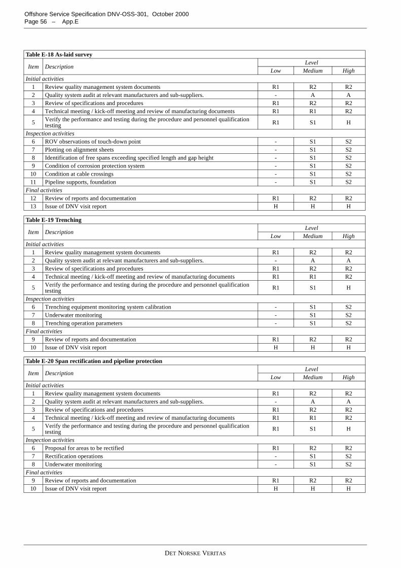
DET NORSKE VERITAS
Offshore Service Specification DNV-OSS-301, October 2000Page 56 – App.E
Table E-18 As-laid survey
Item DescriptionLevel
Low Medium HighInitial activities
1 Review quality management system documents R1 R2 R22 Quality system audit at relevant manufacturers and sub-suppliers. - A A3 Review of specifications and procedures R1 R2 R24 Technical meeting / kick-off meeting and review of manufacturing documents R1 R1 R2
5 Verify the performance and testing during the procedure and personnel qualificationtesting R1 S1 H
Inspection activities6 ROV observations of touch-down point - S1 S27 Plotting on alignment sheets - S1 S28 Identification of free spans exceeding specified length and gap height - S1 S29 Condition of corrosion protection system - S1 S2
10 Condition at cable crossings - S1 S211 Pipeline supports, foundation - S1 S2
Final activities12 Review of reports and documentation R1 R2 R213 Issue of DNV visit report H H H
Table E-19 Trenching
Item DescriptionLevel
Low Medium HighInitial activities
1 Review quality management system documents R1 R2 R22 Quality system audit at relevant manufacturers and sub-suppliers. - A A3 Review of specifications and procedures R1 R2 R24 Technical meeting / kick-off meeting and review of manufacturing documents R1 R1 R2
5 Verify the performance and testing during the procedure and personnel qualificationtesting R1 S1 H
Inspection activities6 Trenching equipment monitoring system calibration - S1 S27 Underwater monitoring - S1 S28 Trenching operation parameters - S1 S2
Final activities9 Review of reports and documentation R1 R2 R2
10 Issue of DNV visit report H H H
Table E-20 Span rectification and pipeline protection
Item DescriptionLevel
Low Medium HighInitial activities
1 Review quality management system documents R1 R2 R22 Quality system audit at relevant manufacturers and sub-suppliers. - A A3 Review of specifications and procedures R1 R2 R24 Technical meeting / kick-off meeting and review of manufacturing documents R1 R1 R2
5 Verify the performance and testing during the procedure and personnel qualificationtesting R1 S1 H
Inspection activities6 Proposal for areas to be rectified R1 R2 R27 Rectification operations - S1 S28 Underwater monitoring - S1 S2
Final activities9 Review of reports and documentation R1 R2 R2
10 Issue of DNV visit report H H H
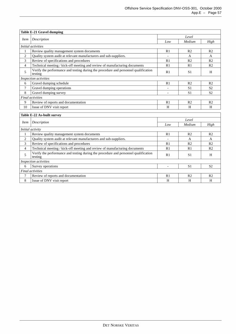
DET NORSKE VERITAS
Offshore Service Specification DNV-OSS-301, October 2000App.E – Page 57
Table E-21 Gravel dumping
Item DescriptionLevel
Low Medium HighInitial activities
1 Review quality management system documents R1 R2 R22 Quality system audit at relevant manufacturers and sub-suppliers. - A A3 Review of specifications and procedures R1 R2 R24 Technical meeting / kick-off meeting and review of manufacturing documents R1 R1 R2
5 Verify the performance and testing during the procedure and personnel qualificationtesting R1 S1 H
Inspection activities6 Gravel dumping schedule R1 R2 R27 Gravel dumping operations - S1 S28 Gravel dumping survey - S1 S2
Final activities9 Review of reports and documentation R1 R2 R2
10 Issue of DNV visit report H H H
Table E-22 As-built survey
Item DescriptionLevel
Low Medium HighInitial activity
1 Review quality management system documents R1 R2 R22 Quality system audit at relevant manufacturers and sub-suppliers. - A A3 Review of specifications and procedures R1 R2 R24 Technical meeting / kick-off meeting and review of manufacturing documents R1 R1 R2
5 Verify the performance and testing during the procedure and personnel qualificationtesting R1 S1 H
Inspection activities6 Survey operations - S1 S2
Final activities7 Review of reports and documentation R1 R2 R28 Issue of DNV visit report H H H
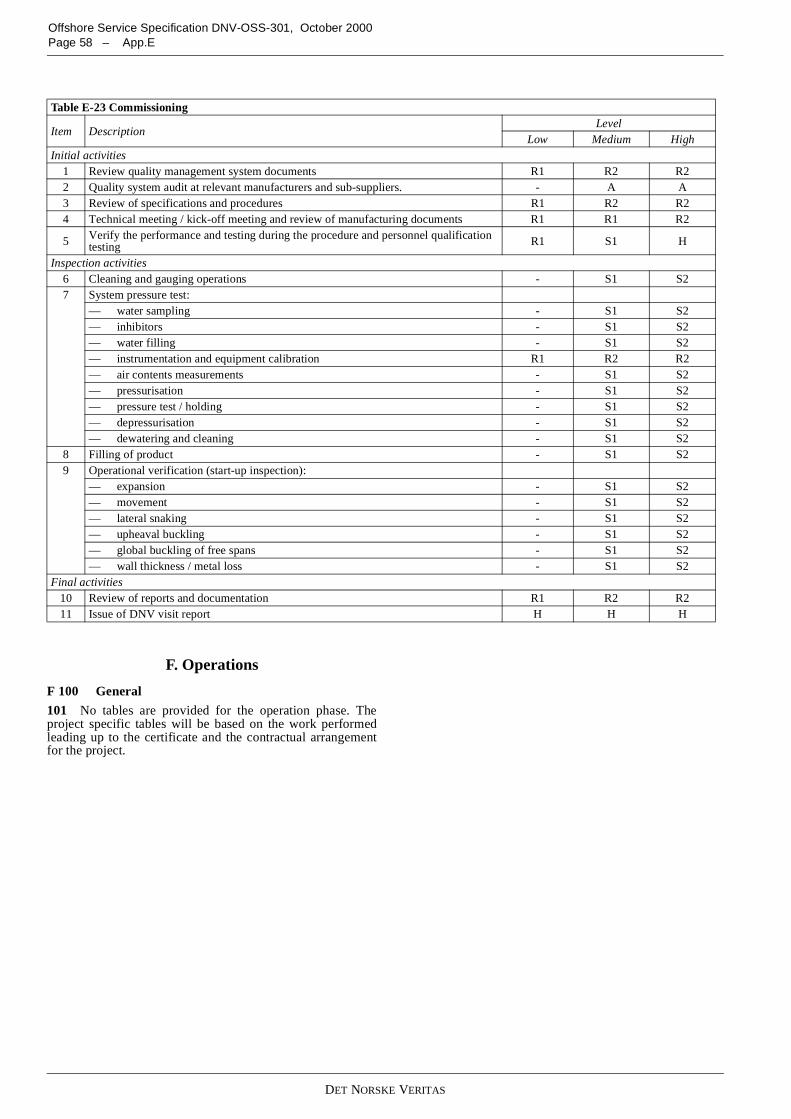
DET NORSKE VERITAS
Offshore Service Specification DNV-OSS-301, October 2000Page 58 – App.E
F. Operations
F 100 General
101 No tables are provided for the operation phase. Theproject specific tables will be based on the work performedleading up to the certificate and the contractual arrangementfor the project.
Table E-23 Commissioning
Item DescriptionLevel
Low Medium HighInitial activities
1 Review quality management system documents R1 R2 R22 Quality system audit at relevant manufacturers and sub-suppliers. - A A3 Review of specifications and procedures R1 R2 R24 Technical meeting / kick-off meeting and review of manufacturing documents R1 R1 R2
5 Verify the performance and testing during the procedure and personnel qualificationtesting R1 S1 H
Inspection activities6 Cleaning and gauging operations - S1 S27 System pressure test:
— water sampling - S1 S2— inhibitors - S1 S2— water filling - S1 S2— instrumentation and equipment calibration R1 R2 R2— air contents measurements - S1 S2— pressurisation - S1 S2— pressure test / holding - S1 S2— depressurisation - S1 S2— dewatering and cleaning - S1 S2
8 Filling of product - S1 S29 Operational verification (start-up inspection):
— expansion - S1 S2— movement - S1 S2— lateral snaking - S1 S2— upheaval buckling - S1 S2— global buckling of free spans - S1 S2— wall thickness / metal loss - S1 S2
Final activities10 Review of reports and documentation R1 R2 R211 Issue of DNV visit report H H H