
DNV-OS-E201: Hydrocarbon Production Plant
46
OFFSHORE STANDARD DET NORSKE VERITAS DNV-OS-E201 HYDROCARBON PRODUCTION PLANT OCTOBER 2000
-
Upload
phamnguyet -
Category
Documents
-
view
267 -
download
2
Transcript of DNV-OS-E201: Hydrocarbon Production Plant
OFFSHORE STANDARD
DET NORSKE VERITAS
DNV-OS-E201
HYDROCARBON PRODUCTION PLANT
OCTOBER 2000
Comments may be sent by e-mail to [email protected] subscription orders or information about subscription terms, please use [email protected] information about DNV services, research and publications can be found at http://www.dnv.com, or can be obtained from DNV,Veritasveien 1, N-1322 Høvik, Norway; Tel +47 67 57 99 00, Fax +47 67 57 99 11.
© Det Norske Veritas. All rights reserved. No part of this publication may be reproduced or transmitted in any form or by any means, includingphotocopying and recording, without the prior written consent of Det Norske Veritas.
Computer Typesetting (FM+SGML) by Det Norske Veritas.Printed in Norway by GCS AS.
If any person suffers loss or damage which is proved to have been caused by any negligent act or omission of Det Norske Veritas, then Det Norske Veritas shall pay compensation to such personfor his proved direct loss or damage. However, the compensation shall not exceed an amount equal to ten times the fee charged for the service in question, provided that the maximum compen-sation shall never exceed USD 2 million.In this provision "Det Norske Veritas" shall mean the Foundation Det Norske Veritas as well as all its subsidiaries, directors, officers, employees, agents and any other acting on behalf of DetNorske Veritas.
FOREWORD
DET NORSKE VERITAS (DNV) is an autonomous and independent foundation with the objectives of safeguarding life, prop-erty and the environment, at sea and onshore. DNV undertakes classification, certification, and other verification and consultancyservices relating to quality of ships, offshore units and installations, and onshore industries worldwide, and carries out researchin relation to these functions.
DNV Offshore Codes consist of a three level hierarchy of documents:
— Offshore Service Specifications. Provide principles and procedures of DNV classification, certification, verification and con-sultancy services.
— Offshore Standards. Provide technical provisions and acceptance criteria for general use by the offshore industry as well asthe technical basis for DNV offshore services.
— Recommended Practices. Provide proven technology and sound engineering practice as well as guidance for the higher levelOffshore Service Specifications and Offshore Standards.
DNV Offshore Codes are offered within the following areas:
A) Qualification, Quality and Safety Methodology
B) Materials Technology
C) Structures
D) Systems
E) Special Facilities
F) Pipelines and Risers
G) Asset Operation
DET NORSKE VERITAS
Offshore Standard DNV-OS-E201, October 2000Contents – Page 3
CONTENTS
CH. 1 INTRODUCTION ................................................ 5
Sec. 1 Introduction .......................................................... 7
A. General....................................................................................7A 100 Introduction....................................................................... 7A 200 Objectives ......................................................................... 7A 300 Organisation of this standard ............................................ 7A 400 Scope and application ....................................................... 7A 500 Assumptions ..................................................................... 7
B. Normative References ............................................................7B 100 General.............................................................................. 7B 200 DNV Offshore Standards, etc. .......................................... 7B 300 Other references................................................................ 8
C. Definitions .............................................................................. 9C 100 Verbal forms ..................................................................... 9C 200 Definitions ........................................................................ 9C 300 Abbreviations..................................................................10
D. Documentation......................................................................11D 100 General............................................................................11
CH. 2 TECHNICAL PROVISIONS ............................ 13
Sec. 1 Design Principles................................................. 15
A. General..................................................................................15A 100 Overall safety principle................................................... 15
B. Design Loads ........................................................................ 15B 100 General principles ...........................................................15B 200 Environmental conditions ...............................................15B 300 Design pressure and temperature....................................15
C. Plant Arrangement and Control............................................15C 100 Operational considerations .............................................15C 200 Monitoring, control and shutdown..................................16C 300 Shutdown devices and failure modes..............................17C 400 General requirements for valves .....................................17C 500 Wellhead control system.................................................17C 600 Subsea control system.....................................................17
Sec. 2 Production and Utility Systems ......................... 18
A. General..................................................................................18A 100 General requirements......................................................18A 200 Interconnection between hazardous and non-
hazardous systems...........................................................18
B. Wellhead and Separation System ......................................... 18B 100 General............................................................................18
C. Separator System ..................................................................19C 100 General............................................................................19
D. Gas Treatment and Compression System.............................19D 100 General............................................................................19
E. Water Injection, Gas Injection and Gas Lift System ............19E 100 General............................................................................19
F. Heating and Cooling Systems...............................................19F 100 General............................................................................19
G. Chemical Injection Systems .................................................19G 100 General............................................................................19
H. Drainage Systems .................................................................19H 100 Open drainage system.....................................................19H 200 Additional requirements for closed drainage systems .... 20
Sec. 3 Relief and Depressurising Systems.................... 21
A. General..................................................................................21A 100 General requirements......................................................21
B. Pressure Relief System .........................................................21B 100 General............................................................................ 21
C. Depressurising System..........................................................21C 100 General............................................................................ 21
D. Disposal System....................................................................22D 100 General............................................................................ 22
Sec. 4 Risers and Crude Export Systems .................... 24
A. General..................................................................................24A 100 General............................................................................ 24A 200 Recognised codes............................................................ 24A 300 Riser disconnection systems (for floating installations). 24A 400 Monitoring and control ................................................... 24
B. Pig Launchers and Receivers................................................24B 100 General............................................................................ 24
C. Crude Export Pump Systems ................................................24C 100 General............................................................................ 24
D. Crude Offloading System (for Floating Installations) ..........24D 100 General............................................................................ 24
Sec. 5 Electrical, Instrumentation and ControlSystems................................................................. 26
A. Electrical Systems.................................................................26A 100 Application ..................................................................... 26
B. Instrumentation and Control Systems...................................26B 100 Application ..................................................................... 26B 200 Scope............................................................................... 26
C. System Requirements ...........................................................26C 100 Clarification and amendments to system
requirements in DNV-OS-D202 ..................................... 26
Sec. 6 Piping................................................................... 27
A. General..................................................................................27A 100 Application ..................................................................... 27A 200 Recognised codes and standards..................................... 27
B. Design Requirements............................................................27B 100 General............................................................................ 27B 200 Wall thickness................................................................. 27B 300 Expansion joints and flexible hoses................................ 27B 400 Valves and special items................................................. 28B 500 Piping connections.......................................................... 28B 600 Supporting elements ....................................................... 28
Sec. 7 Equipment........................................................... 29
A. General..................................................................................29A 100 Application ..................................................................... 29
B. Recognised Codes and Standards .........................................29B 100 Unfired pressure vessels ................................................. 29B 200 Boilers............................................................................. 29B 300 Atmospheric vessels ....................................................... 29B 400 Heat exchangers.............................................................. 29B 500 Pumps ............................................................................. 30B 600 Compressors ................................................................... 30B 700 Combustion engines........................................................ 30B 800 Gas turbines .................................................................... 30B 900 Shafting........................................................................... 30B 1000 Gears ............................................................................... 30B 1100 Couplings........................................................................ 30B 1200 Lubrication and sealing................................................... 30B 1300 Wellhead equipment ....................................................... 30B 1400 Lifting appliances ........................................................... 31
DET NORSKE VERITAS
Offshore Standard DNV-OS-E201, October 2000Page 4 – Contents
Sec. 8 Structures ............................................................ 32
A. General.................................................................................. 32A 100 Application......................................................................32A 200 Recognised codes and standards .....................................32
B. Design Requirements............................................................ 32B 100 General ............................................................................32
C. Manufacture and Testing ...................................................... 32C 100 General ............................................................................32
Sec. 9 Materials and Corrosion Protection ................. 33
A. General.................................................................................. 33A 100 Objective .........................................................................33
B. Principles .............................................................................. 33B 100 General ............................................................................33
C. Specific Requirements.......................................................... 33C 100 Materials for pressure vessels, piping and equipment ....33C 200 Materials for load-carrying parts.....................................33C 300 Rolled steel......................................................................33C 400 Steel forgings ..................................................................33C 500 Steel and iron castings.....................................................33C 600 Aluminium, copper and other non-ferrous alloys ...........33C 700 Bolts and nuts..................................................................33C 800 Sealing materials and polymers ......................................34
D. Material Certificates ............................................................. 34D 100 General ............................................................................34D 200 Type of document ...........................................................34
E. Corrosion Protection............................................................. 34E 100 General ............................................................................34
F. Erosion.................................................................................. 34F 100 General ............................................................................34
Sec. 10 Manufacture, Workmanship and Testing........ 35
A. General.................................................................................. 35A 100 Application......................................................................35A 200 Quality assurance and quality control .............................35A 300 Marking ...........................................................................35
B. Manufacture.......................................................................... 35B 100 Welder's qualification .....................................................35B 200 Welding ...........................................................................35B 300 Heat treatment .................................................................35B 400 Pipe bending....................................................................35
C. Non-destructive Testing (NDT)............................................ 35C 100 General ............................................................................35C 200 Structures ........................................................................36
D. Testing .................................................................................. 36D 100 Testing of weld samples..................................................36D 200 Pressure testing and cleaning ..........................................36D 300 Load testing.....................................................................36D 400 Functional testing ............................................................36
CH. 3 CERTIFICATION AND CLASSIFICATION 37
Sec. 1 Certification and Classification......................... 39
A. General.................................................................................. 39A 100 Organisation of Ch. 3 of the standard .............................39
A 200 Introduction.....................................................................39A 300 Certification or classification principles .........................39A 400 Class designation.............................................................39A 500 Assumptions....................................................................39
Sec. 2 Design Verification............................................. 40
A. General..................................................................................40A 100 Application......................................................................40
B. Specific Requirements for Certification or Classification ...40B 100 General ............................................................................40B 200 Design principles.............................................................40B 300 Electrical, instrumentation and control systems .............40B 400 Piping ..............................................................................40B 500 Materials and corrosion protection .................................40B 600 Manufacture, workmanship and testing ..........................40
C. Documentation Requirements ..............................................40C 100 General ............................................................................40
Sec. 3 Certification of Equipment .............................. 41
A. General..................................................................................41A 100 General ............................................................................41
B. Equipment Categorisation ....................................................41B 100 General ............................................................................41B 200 Pressure containing equipment and storage vessels........41B 300 Miscellaneous items........................................................43
Sec. 4 Survey during Construction.............................. 44
A. General..................................................................................44A 100 General ............................................................................44
B. Quality Assurance or Quality Control ..................................44B 100 General ............................................................................44
C. Module Fabrication...............................................................44C 100 General ............................................................................44
D. Module Installation...............................................................44D 100 General ............................................................................44
E. Specific Requirements in Relation to the Requirements ofCh.2 of this Standard ............................................................44
E 100 Welder qualifications ......................................................44E 200 Welding...........................................................................44
Sec. 5 Surveys at Commissioning and Start-up ......... 45
A. General..................................................................................45A 100 General ............................................................................45
B. System and Equipment Checks ............................................45B 100 General ............................................................................45
C. Functional Testing ................................................................45C 100 General ............................................................................45
D. Start-up .................................................................................45D 100 General ............................................................................45
E. Specific Requirements ..........................................................45E 100 General ............................................................................45
DET NORSKE VERITAS
Veritasveien 1, N-1322 Høvik, Norway Tel.: +47 67 57 99 00 Fax: +47 67 57 99 11
OFFSHORE STANDARDDNV-OS-E201
HYDROCARBON PRODUCTION PLANT
CHAPTER 1
INTRODUCTION
CONTENTS PAGE
Sec. 1 Introduction ............................................................................................................................... 7


DET NORSKE VERITAS
Offshore Standard DNV-OS-E201, October 2000Ch.1 Sec.1 – Page 7
SECTION 1INTRODUCTION
A. General
A 100 Introduction101 This offshore standard contains criteria, technical re-quirements and guidance on design, construction and commis-sioning of offshore hydrocarbon production plants andassociated equipment.
102 The standard is applicable to plants located on floatingoffshore units and on fixed offshore structures of varioustypes.
103 The standard has been written for general worldwide ap-plication. Governmental regulations may include requirementsin excess of the provisions of this standard depending on thesize, type, location and intended service of the offshore unit orinstallation.
A 200 Objectives201 The objectives of this standard are to:
— provide an internationally acceptable standard of safetyfor hydrocarbon production plants by defining minimumrequirements for the design, materials, construction andcommissioning of such plant
— serve as contractual a reference document between suppli-ers and purchasers
— serve as a guideline for designers, suppliers, purchasersand contractors
— specify procedures and requirements for hydrocarbon pro-duction plants subject to DNV certification and classifica-tion.
A 300 Organisation of this standard301 This standard is divided into three main chapters:
Chapter 1: General information, scope, definitions and refer-ences.
Chapter 2: Technical provisions for hydrocarbon productionplants for general application.
Chapter 3: Specific procedures and requirements applicablefor certification and classification of plants in accordance withthis standard.
A 400 Scope and application401 The standard covers the following systems and arrange-ments, including relevant equipment and structures:
— production and export riser systems— well control system— riser compensating and tensioning system— hydrocarbon processing system— relief and flare system— production plant safety systems— production plant utility systems— water injection system— gas injection system— storage system— crude offloading system.
402 The following are considered as main boundaries of theproduction plant, as relevant:
— lower riser connection to sea floor system— control system connection to sea floor system— connection to production buoy— shutdown valve at crude outlet from production plant to
crude storage or loading buoy.
A 500 Assumptions501 The requirements apply to the production plant as such,and presuppose that systems and arrangements as listed beloware provided on the unit or installation:
— safe escape— adequate separation between hydrocarbon processing
plant, utility area, accommodation— fire and explosion safety— emergency shutdown— alarm and intercommunication— utility systems.
502 It is assumed that the subsea production system to whichthe unit or installation is connected, is equipped with sufficientsafe closure barriers to avoid hazards in case of accidentaldrift-off of the unit or dropped objects from the unit or instal-lation.
B. Normative References
B 100 General101 This standard includes references to some recognisedcodes and standards which are frequently specified for produc-tion plants. These shall be used in conjunction with the addi-tional requirements given in this standard, unless otherwiseindicated.
102 Codes and standards other than those stated in this stand-ard may be acceptable as alternative or supplementary require-ments, provided that they can be demonstrated to achieve acomparable, or higher, safety level.
103 Any deviations, exceptions and modifications to the de-sign codes and standards shall be documented and agreed be-tween the contractor, purchaser and verifier, as applicable.
B 200 DNV Offshore Standards, etc.201 The standards listed in Table B1 apply.
Table B1 DNV Offshore Standards and other DNV referencesCode TitleDNV-OS-A101 Safety Principles and ArrangementDNV-OS-B101 Metallic MaterialsDNV-OS-C101 Design of Offshore Steel Structures, General
LRFD methodDNV-OS-C401 Fabrication and Testing of Offshore StructuresDNV-OS-D101 Marine and Machinery Systems and EquipmentDNV-OS-D202 Instrumentation and Telecommunication Sys-
temsDNV-OS-D301 Fire ProtectionDNV-OS-F101 Submarine Pipeline SystemsDNV-OS-F201 Dynamic RisersClassificationNote 6.1
Fire Test Methods for Plastic Pipes, Joints andFittings.
ClassificationNote 41.2
Calculation of Gear Rating for Marine Trans-mission
DNV-RP-A201 Standard Documentation TypesDNV-RP-A202 Documentation of Offshore Projects
Rules for Certification of Flexible Risers andPipesRules for Classification of ShipsRules for Certification of Lifting Appliances
DET NORSKE VERITAS
Offshore Standard DNV-OS-E201, October 2000Page 8 – Ch.1 Sec.1
Guidance note:The latest revision of DNV standards may be found in the list ofpublications at the DNV web site: http://www.dnv.com
---e-n-d---of---G-u-i-d-a-n-c-e---n-o-t-e---
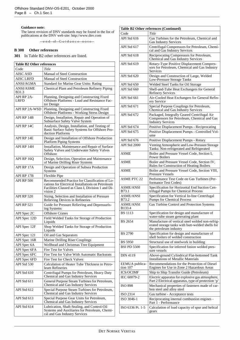
B 300 Other references301 In Table B2 other references are listed.
Table B2 Other referencesCode TitleAISC ASD Manual of Steel ConstructionAISC LRFD Manual of Steel ConstructionANSI/AGMA Standard for Marine Gear Units: RatingANSI/ASMEB31.3
Chemical Plant and Petroleum Refinery Piping
API RP 2A-LRFD
Planning, Designing and Constructing FixedOffshore Platforms - Load and Resistance Fac-tor Design
API RP 2A-WSD Planning, Designing and Constructing FixedOffshore Platforms - Working Stress Design
API RP 14B Design, Installation, Repair and Operation ofSubsurface Safety Valve System
API RP 14C Analysis, Design, Installation, and Testing ofBasic Surface Safety Systems for Offshore Pro-duction Platforms
API RP 14E Design and Installation of Offshore ProductionPlatform Piping Systems
API RP 14H Installation, Maintenance and Repair of SurfaceSafety Valves and Underwater Safety ValvesOffshore
API RP 16Q Design, Selection, Operation and Maintenanceof Marine Drilling Riser Systems
API RP 17A Design and Operation of Subsea ProductionSystems
API RP 17B Flexible PipeAPI RP 500 Recommended Practice for Classification of Lo-
cations for Electrical Installations on PetroleumFacilities Classed as Class I, Division 1 and Di-vision 2
API RP 520 Sizing, Selection and Installation of PressureRelieving Devices in Refineries
API RP 521 Guide for Pressure Relieving and Depressuris-ing Systems
API Spec 2C Offshore CranesAPI Spec 12D Field Welded Tanks for Storage of Production
LiquidsAPI Spec 12F Shop Welded Tanks for Storage of Production
LiquidsAPI Spec 12J Oil and Gas SeparatorsAPI Spec 16R Marine Drilling Riser CouplingsAPI Spec 6A Wellhead and Christmas Tree EquipmentAPI Spec 6FA Fire Test for ValvesAPI Spec 6FC Fire Test for Valve With Automatic BackseatsAPI Spec 6FD Fire Test for Check ValvesAPI Std 530 Calculation of Heater Tube Thickness in Petro-
leum RefineriesAPI Std 610 Centrifugal Pumps for Petroleum, Heavy Duty
Chemical and Gas Industry ServicesAPI Std 611 General Purpose Steam Turbines for Petroleum,
Chemical and Gas Industry ServicesAPI Std 612 Special Purpose Steam Turbines for Petroleum,
Chemical and Gas Industry ServicesAPI Std 613 Special Purpose Gear Units for Petroleum,
Chemical and Gas Industry ServicesAPI Std 614 Lubrication, Shaft-Sealing, and Control-Oil
Systems and Auxiliaries for Petroleum, Chemi-cal and Gas Industry Services
API Std 616 Gas Turbines for the Petroleum, Chemical andGas Industry Services
API Std 617 Centrifugal Compressors for Petroleum, Chemi-cal and Gas Industry Services
API Std 618 Reciprocating Compressors for Petroleum,Chemical and Gas Industry Services
API Std 619 Rotary-Type Positive Displacement Compres-sors for Petroleum, Chemical and Gas IndustryServices
API Std 620 Design and Construction of Large, WeldedLow-Pressure Storage Tanks
API Std 650 Welded Steel Tanks for Oil StorageAPI Std 660 Shell-and-Tube Heat Exchangers for General
Refinery ServicesAPI Std 661 Air-Cooled Heat Exchangers for General Refin-
ery ServiceAPI Std 671 Special Purpose Couplings for Petroleum,
Chemical and Gas Industry ServicesAPI Std 672 Packaged, Integrally Geared Centrifugal Air
Compressors for Petroleum, Chemical and GasIndustry Services
API Std 674 Positive Displacement Pumps - ReciprocatingAPI Std 675 Positive Displacement Pumps - Controlled Vol-
umeAPI Std 676 Positive Displacement Pumps - RotaryAPI Std 2000 Venting Atmospheric and Low-Pressure Storage
Tanks: Non-refrigerated and RefrigeratedASME Boiler and Pressure Vessel Code, Section I,
Power BoilersASME Boiler and Pressure Vessel Code, Section IV,
Rules for Construction of Heating BoilersASME Boiler and Pressure Vessel Code, Section VIII,
Pressure VesselsASME PTC 22 Performance Test Code on Gas Turbines (Per-
formance Test Codes)ASME/ANSIB73.1
Specification for Horizontal End Suction Cen-trifugal Pumps for Chemical Process
ASME/ANSIB73.2
Specification for Vertical In-line CentrifugalPumps for Chemical Process
ASME/ANSIB133.4
Gas Turbine Control and Protection Systems
BS 1113 Specification for design and manufacture ofwater-tube steam generating plant
BS 2654 Manufacture of vertical steel welded non-refrig-erated storage tanks with butt-welded shells forthe petroleum industry
BS 2790 Specification for design and manufacture ofshell boilers of welded construction
BS 5950 Structural use of steelwork in buildingBSI PD 5500 Specification for inferred fusion welded pres-
sure vesselsDIN 4119 Above-ground Cylindrical Flat-bottomed Tank
Installations of Metallic MaterialsEEMUA publica-tion 107
Recommendations for the Protection of DieselEngines for Use in Zone 2 Hazardous Areas
ICS/OCIMF Ship to Ship Transfer Guide (Petroleum)IEC 60079-2 Electric apparatus for explosive gas atmosphere,
Part 2 Electrical apparatus, type of protection ‘p’ISO 898 Mechanical properties of fasteners made of car-
bon steel and alloy steelISO 2314 Gas turbine - Acceptance testsISO 3046-1 Reciprocating internal combustion engines -
Part 1 - PerformanceISO 6336 Pt. 1-5 Calculation of load capacity of spur and helical
gears
Table B2 Other references (Continued)Code Title

DET NORSKE VERITAS
Offshore Standard DNV-OS-E201, October 2000Ch.1 Sec.1 – Page 9
C. Definitions
C 100 Verbal forms101 Shall: Indicates requirements strictly to be followed inorder to conform to this standard and from which no deviationis permitted.
102 Should: Indicates that among several possibilities one isrecommended as particularly suitable, without mentioning orexcluding others, or that a certain course of action is preferredbut not necessarily required. Other possibilities may be appliedsubject to agreement.
103 May: Verbal form used to indicate a course of actionpermissible within the limits of the standard.
104 Agreement or by agreement: Unless otherwise indicated,agreed in writing between manufacturer or contractor and pur-chaser.
C 200 Definitions201 Abnormal conditions: A condition that occurs in a proc-ess system when an operating variable goes outside its normaloperating limits.
202 Alarm: A combined optical and acoustic signal to warnoperators of an abnormal condition and to identify the cause ofthe alarm.
203 Blow-by: A process upset resulting in gas flowingthrough a control valve designed to regulate flow of liquid.
204 Bulkhead: An upright partition wall.
205 Choke valve: Control valve designed to regulate or re-duce pressure.
206 Christmas tree: Combination of valves and connectorsdesigned to control the flow of well fluids, i.e. act as a barrierto the hydrocarbon reservoir.
207 Client: May be either the yard, the owner, or, with re-gard to components, the manufacturer.
208 Closed drains: Drains for pressure rated process compo-nents, piping or other sources which could exceed atmospheric
pressure, such as liquid outlets from pressure vessels and liq-uid relief valves, where such discharges are hard piped withoutan atmospheric break to a drain tank.
209 Cold venting: Discharge of vapour to the atmospherewithout combustion.
210 Completed wells: Wells fitted Christmas trees attachedto the wellhead, such that the flow of fluids into and out of thereservoir may be controlled for production purposes.
211 Contractor: A party contractually appointed by the pur-chaser to fulfil all or any of, the activities associated with de-sign, construction and operation.
212 Control room: Continuously manned room for controlof the installation. The room offers operator interface to theprocess control and safety systems.
213 Control stations (or control room): Those spaces inwhich radio, main navigating equipment, process control andshutdown equipment, fire and gas detection and control equip-ment, central internal communication and alarm equipment,dynamic positioning control system, emergency source ofpower or emergency switchboard are located.
214 Control system: Is a system that receives inputs from op-erators and process sensors and maintains a system within giv-en operational parameters. It may also register importantparameters and communicate status to the operator.
215 Design pressure: The maximum allowable working oroperating pressure of a system used for design. The set point ofPSVs can not exceed this pressure. (Identical to MAWP).
216 Disposal system: A system to collect from relief, ventand depressurising systems. Consists typically of collectionheaders, knock-out drum and vent discharge piping or flaresystem.
217 Double block and bleed: Two isolation valves in serieswith a vent valve between them.
218 Emergency shutdown, (ESD): An action or system de-signed to isolate production plant and ignition sources whenserious undesirable events have been detected. It relates to thecomplete installation. See also safety system.
219 Escape route: A designated path to allow personnelegress to a safe area in the most direct way possible.
220 Explosive mixture: A vapour-air or gas-air mixture thatis capable of being ignited by an ignition source that is at orabove the ignition temperature of the vapour-air or gas-airmixture.
221 Fail safe: Implies that a component or system goes to orremains in the mode that is deemed to be safest on failures inthe system.
222 Failure: An event causing one or both of the followingeffects:
— loss of component or system function— deterioration of functionality to such an extent that safety
is affected.
223 Flammable liquid: A liquid having a flash point below37.8 ºC (100 ºF) and having a vapour pressure not exceeding2.8 kg/cm2 (40 psi absolute) at 37.8 ºC (100 ºF).
224 Flare system: A system which ensure safe disposal ofvapour by combustion.
225 Flash point: The minimum temperature at which a com-bustible liquid gives off vapour in sufficient concentration toform an ignitable mixture with air near the surface of the liq-uid.
226 Hazardous area: Space in which a flammable atmos-phere may be expected at such frequency that special precau-tions are required. See DNV-OS-A101 for a completedefinition including zones etc.
ISO 10433 Petroleum and Natural Gas Industries - Drillingand Production Equipment - Specification forWellhead Surface Safety Valves and Underwa-ter Safety Valves for Offshore Service (Based onAPI Spec 14D)
ISO 10474 Steel and steel products - Inspection documentsISO/R 831 Rules for construction of stationary boilersNACE RP0176 Corrosion Control of Steel Fixed Offshore Plat-
forms Associated with Petroleum ProductionNFPA 37 Standard for the Installation and Use of Station-
ary Combustion Engines and Gas TurbinesNS 3471 Prosjektering av aluminiumskonstruksjoner -
Beregning og dimensjonering (Aluminiumstructures - Design rules)
NS 3472 Steel structures - Design rulesOCIMF Guide to purchasing, manufacturing and testing
of loading and discharge hoses for offshoremooring
TBK 1 - 2 Generelle regler for trykkbeholdere. (Generalrules for pressure vessels) should be used to-gether with Regulation of 11 February 1993 ofboiler plant. (Issued by the Norwegian Directo-rate for fire and explosion prevention (DBE))
TBK 5-6 Generelle regler for rørsystemer. (General Rulesfor Piping Systems)
TEMA Standards for Heat exchangers
Table B2 Other references (Continued)Code Title

DET NORSKE VERITAS
Offshore Standard DNV-OS-E201, October 2000Page 10 – Ch.1 Sec.1
227 Ignition temperature: The minimum temperature re-quired at normal atmospheric pressure to initiate the combus-tion of an ignitable mixture.
228 Independent systems: Implies that there are no function-al relationships between the systems, and they can not be sub-ject to common mode failures.
229 Inert gas: A gas of insufficient oxygen content to sup-port combustion when mixed with flammable vapours or gas-es.
230 Installation: A bottom-founded platform permanentlyaffixed to the sea-floor.
231 Interim class certificate: A temporary confirmation ofclassification issued by the surveyor attending commissioningof the plant upon successful completion.
232 Interlock system: A set of devices or keys that ensurethat operations (e.g. opening and closing of valves) are carriedout in the right sequence.
233 L.E.L. (lower explosive limit): The lowest concentrationof combustible vapours or gases by volume in mixture with airthat can be ignited at ambient conditions.
234 Master valve: A fail safe remotely operated shutdownvalve installed in the main body of the Christmas tree, actingas a well barrier.
235 Maximum allowable working pressure, (MAWP): Themaximum operating pressure of a system used for design. Theset point of PSVs can not exceed this pressure. (Identical to de-sign pressure).
236 Maximum shut in wellhead pressure: The maximum res-ervoir pressure that could be present at the wellhead.
237 Minimum design temperature, MDT: Minimum designoperating or ambient start-up temperature. The lowest predict-able metal temperature occurring during normal operations in-cluding start-up and shutdown situations is to be used. (If nothermal insulation is fitted, then ambient temperature is to beused if this is lower than the temperature of the content.)
238 Open drains: Gravity drains from sources, which are ator near atmospheric pressure, such as open deck drains, drippan drains and rain gutters.
239 Pressure safety valve, (PSV): A re-closing valve de-signed to open and relieve pressure at a defined pressure andrate.
240 Process shutdown, (PSD): Isolation of one or moreprocess segments by closing designated shutdown valves andtripping equipment. The shutdown is initiated through theprocess shutdown system that is a safety system designated tomonitor the production plant.
241 Processing plant: Systems and components necessaryfor safe production of hydrocarbon oil and gas.
242 Production system: The system necessary for safe deliv-ery of hydrocarbon oil and gas. The production system may in-clude separation process, compression, storage and exportfacilities, hydrocarbon disposal, produced water treatment etc.
243 Purchaser: The owner or another party acting on his be-half.
244 Riser system: Includes the riser, its supports, riser endconnectors, all integrated components, corrosion protectionsystem, control system and tensioner system. Riser is a rigid orflexible pipe between the connector on the installation and theseabed (baseplate, wellhead manifold).
245 Rupture (or bursting) disc: A device designed to ruptureor burst and relieve pressure at a defined pressure and rate. Thedevice will not close after being activated.
246 Safety review: Systematic identification and evaluationof hazards and events that could result in loss of life, propertydamage, environmental damage, or the need to evacuate.
247 Safety factor: The relationship between maximum al-lowable stress level and a defined material property, normallyspecified minimum yield strength.
248 Shutdown system: An electronic or mechanical systeminstalled to monitor critical parameters and raise alarms or ex-ecute protective measures based on a pre-defined logic, i.e.PSD and ESD, to bring an undesirable event under control.
249 Shut-in condition: A condition resulting from the shut-ting-in of the plant (see API RP 14C) which is caused by theoccurrence of one or more undesirable events.
250 Slugging flow: Alternating flow of gas and liquid in pip-ing system, typically experienced in systems with large chang-es in height or with flow over long distances, e.g. in pipelinesand risers.
251 Subsea control system: The complete system designedto control the flow of hydrocarbons from subsea wells andpipelines (as applicable). It will typically include surface andsubsea control modules, umbilicals and termination points.
252 Surface controlled sub surface safety valve, (SCSSSV):A fail safe shutdown valve installed in the well bore.
253 Transient condition: A temporary and short-lived condi-tion (such as a surge) which usually does not cause an undesir-able event.
254 Undesirable event: An adverse occurrence or situationor hazard situation that poses a threat to the safety of personnelor the plant.
255 Unit: Any floating offshore structure or vessel, whetherdesigned for operating afloat or supported by the sea bed.
256 Utility systems: Systems providing the installation withsupporting functions. Typical systems are cooling water, gly-col regeneration, hot oil for heating, chemical systems for in-jection, instrument air and power generation system.
257 Verification: An examination to confirm that an activity,a product or a service is in accordance with specified require-ments.
258 Verifier: Body or person who performs verification.
259 Water hammer: Pressure pulse or wave caused by a rap-id change in flow velocity.
260 Wellhead: Connection point between conductor, casing,tubing and the Christmas tree.
261 Wing valve: A fail safe shutdown valve installed on theside outlet of the Christmas tree, acting as a well barrier.
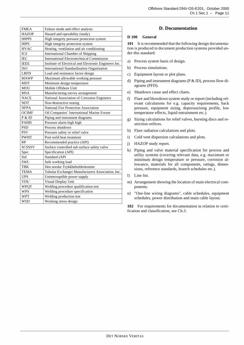
C 300 Abbreviations301 The abbreviations in Table C1 are used.
Table C1 AbbreviationsAbbreviation MeaningAGMA American Gear Manufacturers AssociationAISC American Institute of Steel ConstructionANSI American National Standards InstituteAPI American Petroleum InstituteASD Allowable stress designASME American Society of Mechanical EngineersBS British standard (issued by British Standard Institu-
tion)D & ID Duct and instrument diagramDVR Design verification reportEEMUA Engineering Equipment and Materials Users Asso-
ciationEJMA Expansion Joint Manufacturer’s Association Inc.ESD Emergency shutdownF & G Fire and gasFAT Factory acceptance test
DET NORSKE VERITAS
Offshore Standard DNV-OS-E201, October 2000Ch.1 Sec.1 – Page 11
D. Documentation
D 100 General
101 It is recommended that the following design documenta-tion is produced to document production systems provided un-der this standard:
a) Process system basis of design.
b) Process simulations.
c) Equipment layout or plot plans.
d) Piping and instrument diagrams (P & ID), process flow di-agrams (PFD).
e) Shutdown cause and effect charts.
f) Flare and blowdown system study or report (including rel-evant calculations for e.g. capacity requirements, backpressure, equipment sizing, depressurising profile, lowtemperature effects, liquid entrainment etc.).
g) Sizing calculations for relief valves, bursting discs and re-striction orifices.
h) Flare radiation calculations and plots.
i) Cold vent dispersion calculations and plots.
j) HAZOP study report.
k) Piping and valve material specification for process andutility systems (covering relevant data, e.g. maximum orminimum design temperature or pressure, corrosion al-lowance, materials for all components, ratings, dimen-sions, reference standards, branch schedules etc.).
l) Line list.
m) Arrangement showing the location of main electrical com-ponents.
n) "One-line wiring diagrams", cable schedules, equipmentschedules, power distribution and main cable layout.
102 For requirements for documentation in relation to certi-fication and classification, see Ch.3.
FMEA Failure mode and effect analysisHAZOP Hazard and operability (study)HIPPS High integrity pressure protection systemHIPS High integrity protection systemHVAC Heating, ventilation and air conditioningICS International Chamber of ShippingIEC International Electrotechnical CommissionIEEE Institute of Electrical and Electronic Engineers Inc.ISO International Standardisation OrganisationLRFD Load and resistance factor designMAWP Maximum allowable working pressureMDT Minimum design temperatureMOU Mobile Offshore UnitMSA Manufacturing survey arrangementNACE National Association of Corrosion EngineersNDT Non-destructive testingNFPA National Fire Protection AssociationOCIMF Oil Companies’ International Marine ForumP & ID Piping and instrument diagramsPAHH Pressure alarm high highPSD Process shutdownPSV Pressure safety or relief valvePWHT Post weld heat treatmentRP Recommended practice (API)SCSSSV Surface controlled sub surface safety valveSpec Specification (API)Std Standard (APISWL Safe working loadTBK Den norske TrykkbeholderkomiteTEMA Tubular Exchanger Manufacturers Association, Inc.UPS Uninterruptible power supplyVDU Visual Display UnitWPQT Welding procedure qualification testWPS Welding procedure specificationWPT Welding production testWSD Working stress design

DET NORSKE VERITAS
Offshore Standard DNV-OS-E201, October 2000Page 12 – Ch.1 Sec.1

DET NORSKE VERITAS
Veritasveien 1, N-1322 Høvik, Norway Tel.: +47 67 57 99 00 Fax: +47 67 57 99 11
OFFSHORE STANDARDDNV-OS-E201
HYDROCARBON PRODUCTION PLANT
CHAPTER 2
TECHNICAL PROVISIONS
CONTENTS PAGE
Sec. 1 Design Principles...................................................................................................................... 15Sec. 2 Production and Utility Systems................................................................................................ 18Sec. 3 Relief and Depressurising Systems .......................................................................................... 21Sec. 4 Risers and Crude Export Systems ............................................................................................ 24Sec. 5 Electrical, Instrumentation and Control Systems..................................................................... 26Sec. 6 Piping ....................................................................................................................................... 27Sec. 7 Equipment ................................................................................................................................ 29Sec. 8 Structures.................................................................................................................................. 32Sec. 9 Materials and Corrosion Protection.......................................................................................... 33Sec. 10 Manufacture, Workmanship and Testing ................................................................................. 35

DET NORSKE VERITAS
Offshore Standard DNV-OS-E201, October 2000Ch.2 Sec.1 – Page 15
SECTION 1DESIGN PRINCIPLES
A. General
A 100 Overall safety principle101 Hydrocarbon production systems shall be designed tominimise the risk of hazards to personnel and property by es-tablishing the following barriers:
— preventing an abnormal condition from causing an unde-sirable event
— preventing an undesirable event from causing a release ofhydrocarbons
— safely dispersing or disposing of hydrocarbon gases andvapours released
— safely collecting and containing hydrocarbon liquids re-leased
— preventing formation of explosive mixtures— preventing ignition of flammable liquids or gases and va-
pours released— limiting exposure of personnel to fire hazards.
B. Design Loads
B 100 General principles
101 Design limitations for production plant and componentsshall be clearly defined and shall take account of reservoirproperties, environmental effects, unit motions on floating in-stallations and effects from all operational conditions, includ-ing transients. Typical transient conditions could be associatedwith start-up, shutdown, change-over, settle-out, blow-down,slugging flow etc.
102 All elements of the production plant are to be suitable forthe overall design loads for the plant, and shall be designed forthe most onerous load combination.
103 Design loads for individual components shall be definedwith regard to function, capacity and strength. Mechanical,electrical and control interfaces shall be compatible.
104 Design accidental loads shall be specified and imple-mented in order to prevent unacceptable consequences fromaccidental events. Suitable loads shall be established with re-gard to the accidental events that could occur. See DNV-OS-A101 for determination of relevant accidental loads.
105 Systems and components shall be designed and manu-factured in order to minimise the probability of undesirableevents. Systems and components that statistically have highfailure probabilities shall be avoided. Where this is unavoida-ble, such items should be located to minimise the consequenceof a failure.
106 Where conditions and load combinations are complex,calculations shall be made for each combination of loadings inorder to confirm adequacy of design.
107 The designer shall define maximum imposed loadingson critical equipment and components (e.g. nozzle loadings onpressure vessels, tanks, rotating machinery etc.). Supportingcalculations shall be provided where necessary.
108 Pipework shall be sized so that fluid velocities do not ex-ceed maximum erosion velocity as defined in recognisedcodes, e.g. API RP 14E.
B 200 Environmental conditions201 The overall environmental design criteria and motioncharacteristics for the unit or installation shall also apply for
design of the production plant. Different design criteria mayapply to different phases or conditions, e.g. normal operation,shutdown, survival and transit.
202 Component or system suitability for intended purposeshould be confirmed through test results or other relevant doc-umentation.
203 Where applicable, the following shall be taken into con-sideration when establishing the environmental loads:
— the unit's motions (i.e. heave, roll, pitch, sway, surge, yaw)— wind forces— air and sea temperatures— wave loads— current— snow and ice.
B 300 Design pressure and temperature
301 Systems and components shall be designed to withstandthe most severe combination of pressure, temperature and oth-er imposed loads.
302 The design pressure shall normally include a marginabove the maximum operating pressure, typically 10 % andnormally minimum 3.5 bar.
303 Vapour condensation, pump out, siphon effects etc. shallbe considered when defining the minimum design pressure.
304 The maximum and minimum design temperature shallinclude a margin to the operating conditions to reflect uncer-tainty in the predictions.
305 Typical transients to consider when defining design con-ditions include:
— cold start-up— shut-in, settle out— shutdown— surge— water hammer— 2 phase flow, slugging— depressurising, relief, Joule Thomsen effects— blow-by— cooling failure— thermal expansion.
306 The basis for definition of design conditions shall bedocumented.
C. Plant Arrangement and Control
C 100 Operational considerations
101 The production plant shall be designed to enable safe op-eration during all foreseeable conditions. A hazard and opera-bility (HAZOP) analysis shall be performed to document theadequacy of design.
102 One single maloperation or malfunction within a systemshall not lead to a critical situation for personnel or the unit orinstallation.
Guidance note:Maloperation or malfunction refers to operational and/or techni-cal failure.
---e-n-d---of---G-u-i-d-a-n-c-e---n-o-t-e---

DET NORSKE VERITAS
Offshore Standard DNV-OS-E201, October 2000Page 16 – Ch.2 Sec.1
103 Machinery and equipment shall be located and arrangedto allow safe operation. The requirements of DNV-OS-A101shall apply.
104 All equipment and parts which are to be operated manu-ally or which are subject to inspection and maintenance onboard should be installed and arranged for safe and easy ac-cess.
105 Facilities for safe isolation shall be provided for all partsof the production and utility systems that contain high pres-sure, flammable, or toxic substances and that require to beopened for maintenance or other operations while adjacentparts of the system are energised or pressurised.
Guidance note:The isolation strategy for process systems should be based on anoverall assessment of safety and permit to work systems. The fol-lowing guidance is normally applicable as part of the strategy:
- For infrequent and short term operations, a single block andbleed will normally be adequate (e.g. for replacement of reliefvalves).
- For longer term operations, spectacle blinds or blinds or spac-ers shall be incorporated to enable positive isolation.
- For frequent operations, double block and bleed will be re-quired (e.g. at pig launchers).
- For personnel entry into pressure vessels and tanks, positiveisolations with blinds will be required at all interfaces withpressurised systems.
- Isolation of instrument drain, sample points and other pointswith no permanent connection should be equipped with flang-ed isolation valves or double isolation valves.
---e-n-d---of---G-u-i-d-a-n-c-e---n-o-t-e---
106 Equipment with moving parts or hot or cold surfaces andwhich could cause injury to personnel on contact shall beshielded or protected.
Guidance note:Shields or insulation should normally be installed on surfacesthat can be reached from work areas, walkways, stairs and lad-ders if surface temperatures exceed 70 °C or are below -10 °Cduring normal operation.
---e-n-d---of---G-u-i-d-a-n-c-e---n-o-t-e---
C 200 Monitoring, control and shutdown
201 All equipment and systems shall be equipped with indi-cating or monitoring instruments and devices necessary forsafe operation.
202 Production systems shall be equipped with shutdownsystems. The shutdown systems shall be completely independ-ent of control systems used for normal operation.
Guidance note:Safety systems and control systems for equipment and systemswith predictable and limited damage potential may be combinedonly if the probability for common mode failure is demonstratedto be low.Additional shutdown signal from process control system to shut-down valves and breakers may, however, be acceptable.
---e-n-d---of---G-u-i-d-a-n-c-e---n-o-t-e---
203 Systems that could endanger the safety if they fail or op-erate outside pre-set conditions shall be provided with auto-matic shutdown. The shutdown system shall monitor criticalparameters and bring the system to a safe condition if specifiedconditions are exceeded. The protection principles shall bebased on API RP 14C.
Guidance note:This will normally apply to all permanently installed processingsystems on production installations.Automatic shutdown systems may not be required for minor sys-tems continuously attended during normal operation. This will be
subject to adequate monitoring and sufficient response timeavailable for manual shutdown.
---e-n-d---of---G-u-i-d-a-n-c-e---n-o-t-e---
204 Systems designed for automatic shutdown shall also bedesigned to enable manual shutdown.
205 All shutdowns shall be executed in a predetermined log-ical manner. The shutdown system shall normally be designedin a hierarchical manner where higher level shutdowns auto-matically initiate lower level shutdowns. Emergency shut-down shall initiate a process shutdown.
206 Definition of the shutdown logic and required responsetimes are to be based on consideration of dynamic effects andinteractions between systems.
207 Inter-trips between process systems shall be initiated asa result of any initial event which could cause undesirable cas-cade effects in other parts of the plant before operator interven-tion can be realistically expected.
208 The shutdown principles given in DNV-OS-A101 shallbe adhered to.
209 The highest or most severe levels of emergency shut-down shall, as a minimum, result in the following actions re-lated to the production plant, (note that other actions will alsobe required, see DNV-OS-A101):
a) All actions described in 210.
b) Closure of all surface and subsea tree valves, includingSCSSSV.
c) Depressurising of production plant.
d) Closure of pipeline isolation valves, if installed.
210 The highest or most severe level of process shutdownshall, as a minimum, result in the following actions:
a) Closure of master and wing or injection valves (on surfacetrees).
b) Closure of wing valve (or other acceptable barrier valve onsubsea trees).
c) Closure of process shutdown valves.
d) Closure of riser ESD valves (incoming and outgoing).
e) Closure of gas lift and gas injection valves.
f) Trip of driven units like gas compressors, pumps, processheaters etc.
g) Isolation or trip of utility systems serving the productionplant.
211 There shall be two independent levels of protection toprevent or minimise the effects of a single malfunction or faultin process equipment and piping systems (including their con-trols). The two levels of protection shall be provided by func-tionally different types of safety devices to reduce theprobability for common cause failures.
Guidance note:Shutdown at the primary protection level should be possiblewithout the secondary level being initiated. As an example, thePAHH (Pressure alarm high high) as primary overpressure pro-tection should react to shut-off inflow before the PSV reaches setpressure.
---e-n-d---of---G-u-i-d-a-n-c-e---n-o-t-e---
212 Activation of the shutdown system shall be sounded byalarms at the control station. Central indicators shall identifythe initiating device or cause of the safety action and the shut-down level initiated.
213 From the control station, it shall be possible to verify,the operating status of devices affected by the shutdown action(e.g. valve position, unit tripped, etc.). Such status shall be

DET NORSKE VERITAS
Offshore Standard DNV-OS-E201, October 2000Ch.2 Sec.1 – Page 17
readily available. The screen used for shutdown status shall bededicated for this purpose.
Guidance note:Such status should be available without having to page throughseveral VDU pictures. Alarm list and highlights of shutdown im-perfections should be used. Large screens are recommended in-stead of VDUs for display of shutdown status.
---e-n-d---of---G-u-i-d-a-n-c-e---n-o-t-e---
214 Shutdown commands should not be reset automatically.As a rule, important shutdown devices shall only be reset lo-cally after the initiating shutdown command has been reset bythe operator.
215 Activation of depressurisation valves can be incorporat-ed in either the process or emergency shutdown.
216 Additional requirements for instrumentation, controland safety systems are found in DNV-OS-D202.
C 300 Shutdown devices and failure modes
301 Systems, actuated devices and controls shall be designedfail safe. This means that failure of the controls or associatedsystems will result in the system going to the operational modethat has been pre-determined as safest. This normally impliesthat shutdown valves will ‘fail to closed’ position, and depres-surisation valves ‘fail to open’ position. Sensors shall havenormally energised, closed circuits and contacts.
302 Where required, stored energy devices for actuatorsshall be designed, located and protected to ensure that the failsafe function is not impaired by defined design accidentalevents.
303 Pneumatic and hydraulic systems shall be monitored.Process shutdown of such systems shall be initiated if pressurefalls below a level where functionality is lost.
304 Components which, for safety reasons, are required tomaintain functionality for a specific period of time during anemergency (e.g. fire resistance of valves) shall be verified ashaving the appropriate qualifying properties, e.g. by tests, cal-culations etc.
C 400 General requirements for valves
401 Valves shall have position indicating devices that areeasy to see and to understand.
402 Remote operated valves, and valves which are part of anautomatic safety system, shall have position transmitters giv-ing status at the control or shutdown panel.
403 Control valves and shut off valves shall be designed toprevent unacceptable pressure surges on closure either bycommand or by loss of control signal.
404 Requirements for fire protection and testing of shutdownvalves isolating segments shall be as defined in DNV-OS-D301.
405 See also specific requirements for valves given in Sec.6.
C 500 Wellhead control system
501 The principles described in DNV-OS-D202 shall applyto control of wellhead valves on surface trees, including thesurface controlled sub surface safety valve (SCSSSV). The po-sition of the SCSSSV may, however, be derived from the pres-sure of the control line.
502 Hydraulic oil return lines from the SCSSSV could becontaminated by hydrocarbons if a leak occurs downhole. Thereturn system shall therefore be segregated from other systems,and shall be regarded as a secondary grade source for area clas-sification purposes.
503 In order to minimise wear, closure of wellhead valvesshall be in the following sequence: wing valve before mastervalve before SCSSSV. Failure of a valve to close shall not pre-vent closure of the remaining valves.
504 Oil levels and supply pressures from hydraulic wellheadcontrol panel shall be monitored. Wellhead valves shall beshutdown in a controlled manner if either pressure falls belowa level where functionality may be lost.
505 The wellhead shutdown system shall normally be de-signed for complete isolation of all wells within 30 s.
C 600 Subsea control system
601 The requirements in 602 to 608 apply to control of sub-sea wellhead and injection valves, manifold valves, and pipe-line isolation valves which act as barriers to the reservoir orbetween the installation and significant inventories in pipe-lines. The requirements also apply to control of sub surfacevalves in subsea wells.
Guidance note:Installation of pipeline isolation valves is not a requirement ofthis standard, but if such valves are installed to reduce risks onthe installation then relevant requirements for the control sys-tems will apply.
---e-n-d---of---G-u-i-d-a-n-c-e---n-o-t-e---
602 The subsea control system shall be fail safe. Controlledshutdown shall be possible after failures in system elements(e.g. failure of pilot controls, multiplex signals or electro-hy-draulic signals).
Guidance note:
Where appropriate, this could be achieved by depressurising thecontrol fluid supply line through a dump valve that is independ-ent of other subsea controls.
---e-n-d---of---G-u-i-d-a-n-c-e---n-o-t-e---
603 The response time of the complete system (i.e. time tocomplete the demanded action) shall be defined. Where rele-vant, two response levels may be defined to reflect normal op-eration and fail safe operation when e.g. multiplex controlshave failed.
604 The subsea control system shall receive inputs from theshutdown system. Shutdown of topside production systems orriser ESD valves shall normally result in closure of subseawing valve or other barrier valve local to the wellhead.
605 High level ESD on the installation shall result in closureof all subsea barrier valves, including the sub surface valve.
606 The general requirement for segregation between con-trol and shutdown systems is not mandatory for subsea controlsystems, which may incorporate operational control functions(e.g. choke valve controls or status, pressure and temperaturemonitoring).
607 Control fluids used in open control systems that drain tosea shall be harmless to the environment.
608 Possible leakage of well bore fluids into a closed controlsystem from the SCSSSV shall be considered in the design.See 502.

DET NORSKE VERITAS
Offshore Standard DNV-OS-E201, October 2000Page 18 – Ch.2 Sec.2
SECTION 2PRODUCTION AND UTILITY SYSTEMS
A. General
A 100 General requirements
101 The plant shall be divided into segments. Each segmentshall be segregated by shutdown valves that are operated fromthe shutdown system. The valves shall segregate productionsystems based on consideration of plant layout, fire zones, de-pressurising system and pressure ratings.
Guidance note:The shutdown valves should divide the process into segmentssuch that a leakage from any segment does not represent unac-ceptable consequences. The adequacy of selected segmentationshould be addressed through a HAZOP study.
---e-n-d---of---G-u-i-d-a-n-c-e---n-o-t-e---
102 The following valves shall be actuated and designated asshutdown valves:
— wing, master, injection and sub surface (downhole) valvesassociated with wellhead trees
— pipeline riser valves— riser gas lift valves— segregation valves between systems with different design
pressure (MAWP)— process segmenting valves.
103 The production and utility systems shall be fitted withsufficient drain and vent points to enable draining and depres-surisation of all segments in a controlled manner. They shall bepermanently or temporarily connected to the closed flare, ven-tilation and drain disposal systems. See H.
Guidance note:
Consideration should be given to installing 2 block valves in se-ries at drain points from high pressure systems (typically 300#rating and above). This will enable shut off if ice or hydratesform in one of the valves as pressure is bled off.Facilities to enable purging of systems with inert gas (e.g. nitro-gen) should be incorporated if such operations are required byoperating or ‘Permit to Work’ procedures.
---e-n-d---of---G-u-i-d-a-n-c-e---n-o-t-e---
104 All atmospheric vessels where an explosive atmospheremay occur due to presence of flammable substance shall be in-erted with blanket gas or inert gas if there is a possibility of airingress.
105 Interfaces between high pressure and low pressure sys-tems that are not open and protected during normal operationsshall be isolated by spades, blinds or other positive means. Aninterlocked double block and bleed may also be accepted.These valves are to be rated for the highest pressure.
106 Piping with a bore less than 19 mm (¾ inch) shall beavoided in process piping systems where practicable. If used,particular attention shall be paid to providing suitable support-ing arrangements to prevent damage caused by vibrations, rel-ative thermal expansions or other imposed loads from adjacentpipework or operations.
107 Utility systems are to be in accordance with require-ments in this section. Additional requirements for general util-ity services are given in DNV-OS-D101.
A 200 Interconnection between hazardous and non-haz-ardous systems
201 Service and utility systems (e.g. steam, heating medium,cooling medium, compressed air, drains etc.) that are connect-ed to systems containing flammable or toxic liquids or gasesare normally not to be combined with similar systems locatedin non-hazardous areas or connected to non-hazardous sys-tems.
202 Any connections between hazardous and non-hazardoussystems shall be avoided. Where this is impracticable, suchconnections shall be designed to eliminate or control the riskof ingress of hazardous material from one system to the otherdue to incorrect operation or leaks. The following issues shallbe fulfilled before systems are interconnected:
a) Identify possible failure modes and define a realistic rangeof leak sizes.
b) Evaluate possible consequences of cross contamination.
c) Describe and evaluate reliability, maintainability and test-ability of active and passive protection systems (e.g. liquidseals, non-return valves, detectors, actuated valves, prima-ry and secondary loops etc.).
If the potential consequences of cross contamination are foundto be significant, or if the reliability of protective measures aredifficult to maintain or verify, then separate systems shall bespecified.
Guidance note:Investigations following incidents have shown that gas can mi-grate backwards against the flow of liquids and past checkvalves. Check valves alone are not normally regarded as reliabledevices for prevention of cross contamination.
---e-n-d---of---G-u-i-d-a-n-c-e---n-o-t-e---
B. Wellhead and Separation System
B 100 General
101 Mechanical handling of heavy components in wellheadareas shall include attention to avoiding damage to processequipment. Where possible, hydrocarbon piping associatedwith other systems should not be routed through the wellheadarea.
102 Wellheads shall be designed for maximum shut in well-head pressure, considering the accuracy of predicted reservoirconditions (pressure, density etc.). A safety margin of 10 %should be incorporated in the design pressure.
103 Flow lines, piping, instrumentation and structures whichare connected to, or adjacent to, wellheads shall be designed toallow relative vertical and lateral movement between wellheadand installation. (This can be e.g. due to thermal expansion,movement caused by waves etc.).
104 Conductor tensioning systems, where required, shall besubject to a failure mode and effect analysis (FMEA), or anequivalent study.
Guidance note:The FMEA should identify critical components and functions.Appropriate fail safe actions, redundancy and alarms should beincorporated to ensure the integrity of the well barrier.
---e-n-d---of---G-u-i-d-a-n-c-e---n-o-t-e---
DET NORSKE VERITAS
Offshore Standard DNV-OS-E201, October 2000Ch.2 Sec.2 – Page 19
C. Separator System
C 100 General101 The separators shall have sufficient capacity to separatethe components of the well stream, and effective means for re-moval of sand and water.
102 Design of separator and separator control system shallinclude consideration for list and rolling of the unit, where rel-evant.
D. Gas Treatment and Compression System
D 100 General101 Liquid scrubbers with appropriate internals (e.g. mistpads) shall be installed immediately upstream of gas compres-sors. The compressor train shall be tripped or otherwise pro-tected if liquid levels reach an unacceptable level within anupstream scrubber.
102 Gas coolers in systems with significant pressure differ-ential between the gas and cooling medium side shall be fittedwith quick acting relief devices (e.g. bursting discs). See APIRP 521.
103 Compressor seal systems shall be monitored for leakage.The compressor shall be automatically tripped and depressu-rised if unacceptable leaks or other malfunctions are detected.
104 Compressor recycle line shall be self-draining to the tie-in point upstream of the compressor, with the recycle linevalve located at the high point.
105 The design pressure and temperature of the process seg-ment that contains the compressor shall include account of set-tle-out conditions.
106 Compressor recycle valves which are required to operateas part of emergency depressurisation shall be fitted with sep-arate solenoids controlled from the shutdown system.
107 Location of vent points from the glycol regeneration re-boiler shall include consideration of emissions of harmful sub-stances (e.g. aromatics) and their effect on personnel.
108 Fuel gas treatment systems shall include instrumentationthat will trip the fuel gas supply if fuel gas properties exceedacceptable limits for the fired unit or engine.
E. Water Injection, Gas Injection and Gas LiftSystem
E 100 General101 A non-return valve and an automatic shutdown valveshall be fitted at the injection point to the well.
102 Water injection pipework and wellheads on units whichare intended to operate in areas with ambient design tempera-tures below -5 °C shall be fitted with winterisation to preventfreezing during periods of shutdown.
Guidance note:This requirement may be waived if suitable operational proce-dures are established.
---e-n-d---of---G-u-i-d-a-n-c-e---n-o-t-e---
103 If produced water is to be re-injected into the reservoir,then overboard dump lines and drain lines from water injectionpump seals shall be considered for area classification due todissolved hydrocarbon gases.
104 Safety showers and eye washing stations shall be in-stalled at locations where biocides or other harmful substancesare stored and handled.
F. Heating and Cooling Systems
F 100 General
101 Interconnections between systems serving hazardousand non-hazardous plants are normally not accepted. SeeA200.
102 Primary heating or cooling circuits in hydrocarbon proc-ess systems shall have facilities to detect small hydrocarbonleakages. See D103 for protection against major leakages.
103 The design temperature of both sides of heat exchangersshall be determined by the hottest fluid.
104 Heat exchangers shall be protected from thermal expan-sion of blocked in fluids when flow is maintained through theother side.
G. Chemical Injection Systems
G 100 General
101 Non-return valves shall be installed at injection points toproduction systems.
102 The design pressure of a chemical injection pump shall,as a minimum, be the same as the system into which it injects.
103 A bunded area with adequate drainage shall be providedfor storage and emptying of transportable tank containers. In-compatible chemicals shall be located in separate bunds.
104 Piping from transportable tank containers or boat load-ing stations to permanent storage tanks or other facilities shallbe self draining.
105 Provisions for lashing of transportable tank containersshall be incorporated in the bunded area. Permanent piping in-stallations and hose couplings shall be protected against dam-age from handling operations.
106 Injection systems supplied with cryogenic liquids (e.g.liquid nitrogen) shall be installed in insulated bunds that aredesigned to collect any leaks and prevent adverse low temper-ature effects on structures or other equipment.
107 Safety showers and eye washing stations shall be in-stalled at locations where harmful substances are stored andhandled.
H. Drainage Systems
H 100 Open drainage system
101 See DNV-OS-D101 for requirements for bilge systemson floating installations.
102 Production equipment from which spillage and minorleaks can be expected shall be located above drip trays orcoamings which will collect and direct escaped fluids to anopen drainage system. Drain points are to be installed at oppo-site sides of the tray.
Guidance note:This will normally apply to:
— atmospheric tanks and pressure vessels with multiple flang-es and instruments
— pumps— heat exchangers— seal and lubrication oil systems under rotating machinery— sample points— pig receivers and launchers, etc.
---e-n-d---of---G-u-i-d-a-n-c-e---n-o-t-e---

DET NORSKE VERITAS
Offshore Standard DNV-OS-E201, October 2000Page 20 – Ch.2 Sec.2
103 The capacity of the drip tray shall be based on an assess-ment of potential leak rates and may normally be nominal forequipment other than pressure vessels and tanks, (e.g. approx-imately 50 mm coaming).
104 The capacity of drip trays under large tanks, pressurevessels and heat exchangers should be based on an assessmentof the number of leak sources, and volume and consequence ofleak e.g. onto equipment or deck below.
Guidance note:A capacity to hold 5 % of the volume can normally be regardedas adequate, provided that there is also sufficient capacity of thecollection system with headers etc. Catastrophic ruptures can behandled through the general open deck drain system.
---e-n-d---of---G-u-i-d-a-n-c-e---n-o-t-e---
105 An open deck drain system shall be installed to collectleakage from representative process pipework based on oper-ating conditions. The system shall also be designed to handlerain water and fire water, and, for floating installations, alsosea water.
Guidance note:The objectives that should be considered when designing theopen deck drain system include:
- removal of liquids that could fuel a fire- control the spread of flammable liquids from one fire zone to
the next- maintain escape routes passable- limit liquid rundown onto sensitive equipment or structures
below the source of the leak e.g. life saving appliances, risers,tank deck, escape routes
- minimising environmental damage.Smaller process leaks and rain water are typically collected ingullies and led to a treatment system. Gullies are normally locat-ed at regular intervals throughout the production plant area.
Fire water and large process leaks of oil are typically collected ingullies and routed to a safe location for disposal (e.g. overboard)through overflows and gutters.
---e-n-d---of---G-u-i-d-a-n-c-e---n-o-t-e---
106 Drains systems for areas that are classified as hazardousshall be separate from drain system for non-hazardous areas.
Guidance note:
The collection system (consisting of collection piping and draintank with vent) for the hazardous open drain system should becompletely separate from the collection system for the non-haz-ardous system.
---e-n-d---of---G-u-i-d-a-n-c-e---n-o-t-e---
107 If there is a possibility of air ingress, the treatment plantshall be inerted with blanket gas or inert gas. Measures shall betaken to prevent spread of fire through the drainage system(e.g. water seals with level alarms).
H 200 Additional requirements for closed drainage sys-tems
201 The production plant shall, as a minimum, be equippedwith a closed drainage system for hydrocarbons. See A103.
202 The open and closed drainage systems shall be separate.See A200 for requirements for separation.
203 For floating installations, drainage systems shall operatesatisfactorily during all sea states and operational trim of theinstallation.
204 See DNV-OS-D101 for requirements for collection ofdrainage products within slop tanks on floating installations.
DET NORSKE VERITAS
Offshore Standard DNV-OS-E201, October 2000Ch.2 Sec.3 – Page 21
SECTION 3RELIEF AND DEPRESSURISING SYSTEMS
A. General
A 100 General requirements101 The production plant shall be provided with pressure re-lief, vent, depressurising and disposal systems designed to:
— protect equipment against excessive pressure— minimise the escape of hydrocarbons in case of rupture— ensure a safe collection and discharge of released hydro-
carbon fluids.
102 The systems shall be designed to handle the maximumrelief rates expected due to any single equipment failure or di-mensioning accident situation (e.g. caused by blocked outlet orfire). Consideration shall also be given to possible cascade ef-fects where upsets in one process segment can cause upsetselsewhere.
103 Block valves installed in connection with pressure re-lieving devices (PSV, rupture disc or depressurisation valve)shall be interlocked or locked open as appropriate. Blockvalves or control valves are not to be installed in relief collec-tion headers.
Guidance note:Flare gas recovery systems are exemptions.
---e-n-d---of---G-u-i-d-a-n-c-e---n-o-t-e---
104 Discharges from relief valves, rupture discs, and auto-matic and manual depressurisation valves are to be routed to asafe location.
105 Supply and discharge piping to and from relieving de-vices shall be self-draining away from the relief device back topressure source and to knockout drum, as applicable. The tie-in to collection header shall normally be at the top of the head-er, preferably at 45 ° to the flow direction in the header.
106 Relief and blowdown devices shall be located to enableeffective relief of the complete volume they protect withoutobstructions to flow, e.g. flow through control valves, mistpads etc.
107 The design of piping, valves, supports and knock outdrum shall include consideration of generation of low temper-atures, hydrates, possible slugging flow, and heat input fromthe flare during normal and emergency conditions.
B. Pressure Relief System
B 100 General101 All pressure systems shall be fitted with pressure reliefdevices that are set at no higher than the design pressure(MAWP) of the system. The devices shall have suitable capac-ity and characteristics to limit pressure build up to within limitsallowed in the design code for the system or component.
Guidance note:The limits are normally:
- 110 % of MAWP for non-fire relief- 120 % of MAWP for fire relief.Design cases that should be considered include:
- blocked outlet- failure of pressure control valve- gas blow by at level control valve- excessive energy input (from heater or fire)- rupture of heat exchanger tube- blocked in volume (liquid expansion)
- backflow.Two phase flow should be identified for the design cases listedabove.
If design for full flow relief proves impractical, then alternativemeasures may be considered. These include high integrity pres-sure systems (HIPPS). The acceptability of such systems shall beconsidered on a case by case basis and will be dependent upondemonstration of adequate reliability and response of the com-plete system from detector to actuated device. The reliability tar-get should be an order of magnitude higher than critical failure ofa typical relief device. Such systems may not replace the PSV ona pressure vessel.
---e-n-d---of---G-u-i-d-a-n-c-e---n-o-t-e---
102 If more than one device is necessary to obtain the re-quired relief rate, then the system shall be equipped withvalves of sufficient capacity to enable any one device to be outof service without reducing the capacity of the system to below100 % of design rate.
103 Block valves are not normally to be installed whereequipment is protected by a single relief valve. Downstreamblock valves may, however, be installed if discharge is to acommon relief header. See also A103.
104 To prevent over pressurisation of the PSV dischargeside, all downstream isolation valves in multiple PSV installa-tions shall be open unless the PSV is removed for maintenance.
105 Imposed loadings on relief valve nozzles shall be avoid-ed by means of careful layout of piping and design of supports.
106 Rupture discs are to be used in systems containing sub-stances that could render a pressure relief valve ineffective, orwhen rapid pressure rise can be predicted.
107 In installations where rupture discs are installed in serieswith PSV or other rupture disc, the volume between the devic-es shall be monitored for leakage and increase in pressure. Analarm shall be given at the control centre if a leak is detected.
C. Depressurising System
C 100 General
101 The depressurising system shall ensure safe collectionand disposal of hydrocarbons during normal operations andduring emergency conditions.
Guidance note:Elements of the system will normally be regarded as part of thesafety systems and should be designed to integrate with the over-all safety strategy for the plant.It is normally recommended that detection of fire or gas releasein the process area results in automatic depressurisation of theproduction plant. See also Sec.1 C209. Where this is not the case,the HAZOP should include due consideration of the effects of theadded time before depressurisation is initiated, allowing for man-ual actions.
---e-n-d---of---G-u-i-d-a-n-c-e---n-o-t-e---
102 The depressurising system shall be as simple as practi-cable and shall be designed according to the fail safe principle.This normally implies that blow down valves are spring return,and fail to open position.
103 Process systems that contain significant energy shall bedepressurised during an emergency situation. The rate of de-pressurising shall be sufficient to ensure that rupture will notoccur in case of external heat input from a fire.

DET NORSKE VERITAS
Offshore Standard DNV-OS-E201, October 2000Page 22 – Ch.2 Sec.3
Guidance note:The maximum locked-in energy content should be based on as-sessment of the potential for incident escalation. Blocked in vol-ume equivalent to 1000 kg of hydrocarbons is commonlyregarded as acceptable if the plant is located in an open area.
The capacity of the system should be based on evaluation of:
- system response time- heat input from defined accident scenarios- material properties and material utilisation ratio- other protection measures, e.g. active and passive fire protec-
tion- system integrity requirements.
Fire water systems are not normally regarded as reliable protec-tion measures for systems exposed to jet fires.
---e-n-d---of---G-u-i-d-a-n-c-e---n-o-t-e---
104 It shall be possible to activate the depressurising systemmanually from the control station, in addition to any automaticactions initiated through the ESD or F&G systems.
105 The piping layout should aim to provide protection fromexternal loads (e.g. from fire, explosion, missile impact,dropped or swinging loads).
106 During an dimensioning accidental event, the integrityand functionality of depressurising piping and valves shall bemaintained for the required period of time in order to ensurethat successful depressurisation can be performed.
Guidance note:To ensure this functionality, passive fire protection or othermeasures may be required to ensure that depressurisation is initi-ated before excessive temperatures are reached.
---e-n-d---of---G-u-i-d-a-n-c-e---n-o-t-e---
107 See Sec.1 for general requirements for controls andvalves.
D. Disposal System
D 100 General
101 The disposal system(s) shall collect from relief, ventila-tion, pressure control and depressurising systems. Liquidsshall be separated in a knock out drum before discharge.
Guidance note:The design should be suitable for the disposal rate due to pressurecontrol valve failure.
---e-n-d---of---G-u-i-d-a-n-c-e---n-o-t-e---
102 The gas disposal system shall be designed such that thelowest pressure sources can enter the system without unaccept-able reduction in capacity due to back pressure.
Guidance note:This may result in a requirement for 3 systems, one for high pres-sure sources, one for low pressure sources and one for atmos-pheric ventilation.
---e-n-d---of---G-u-i-d-a-n-c-e---n-o-t-e---
103 The gas disposal systems shall be continuously purgedwith nitrogen or fuel gas supplied upstream in headers and sub-headers.
104 The knock out drum shall have capacity to remove slugsand droplets that would not be completely burned in the flareor which could fall back onto the installation.
Guidance note:Typical performance standards for knock out drums are:
- separation of liquid droplets down to 300-400 micron withnormal liquid level at start of depressurising
- capacity to hold entrained liquid from process segments whileisolation valves are closing, minimum 90 s
- capacity to hold liquid from condensing vapours- capacity to hold liquid from a typical process segment that has
not been successfully isolated while depressurising valve isopen (e.g. inflow from well or pipeline). The liquid holdingcapacity should be based on evaluation of the time requiredfor manual intervention and the number and flow rates of pos-sible sources. It should be considered to install alarms onvalves that could cause significant inflow if they fail to oper-ate or operate inadvertently. See also Sec.2
- in estimating capacity to hold liquid, the pump out rate shouldnot be taken into consideration.
---e-n-d---of---G-u-i-d-a-n-c-e---n-o-t-e---
105 The sizing and internal design of knock out drum to en-sure efficient liquid removal shall also include considerationof:
— dynamic effects caused by unit motions (e.g. sloshing) forfloating installations
— the possibility of gas flow picking up liquid slugs whenpassing through the drum.
106 The knock out drum shall be fitted with high level mon-itoring which initiates a complete process shutdown if designlevels are exceeded.
107 Cold vents shall be located at a safe distance from igni-tion sources and ventilation intakes. An extinguishing systemshall be fitted to extinguish the vent if it is accidentally ignitedby e.g. lightning or static discharge.
108 The dew point of vented gas is to be such that it will notcondense and fall back on the plant when discharged at theminimum anticipated ambient temperature.
109 Open vent discharge piping shall be protected againstthe effects of rain and ingress by foreign bodies.
Guidance note:It may be appropriate to install:
- a 10 mm ‘weep-hole’ to drain out any rainwater- a wire mesh (or ‘bird cage’) at outlet- flame arrestors.
---e-n-d---of---G-u-i-d-a-n-c-e---n-o-t-e---
110 Flares shall normally be ignited by a continuous pilotflame. The pilot flame shall be supplied with a reliable sourceof gas. A back-up system shall be provided to secure supply ofgas during all operating conditions.
111 In the case of a gas recovery system, the flare may be ig-nited by a pilot flame or an automatic ignition system.
112 An automatic ignition system shall be activated by boththe PSD and ESD system.
113 The ignition system shall have the same high reliabilityas the PSD or ESD system. Sources of single failure should beavoided.
114 The gas cloud formation and explosion consequencesthat could occur due to an ignition failure shall be analysed andassessed as acceptable.
115 The ignition timing shall be decided from flow calcula-tions for representative release scenarios.
116 The ignition system shall be provided with adequate re-dundancy to ensure operation as and when required.
Guidance note:This may mean:
- back-up or reservoir nitrogen- minimum two attempts in each sequence- parallel components as required to remove sources of single
failure.
---e-n-d---of---G-u-i-d-a-n-c-e---n-o-t-e---

DET NORSKE VERITAS
Offshore Standard DNV-OS-E201, October 2000Ch.2 Sec.3 – Page 23
117 Flare and cold vent structures shall be fitted with stairs,ladders, handrails or guards to provide safe personnel accessfor maintenance and inspection. Where appropriate, securingpoints for personnel harness shall be provided.
118 The flare and vent systems shall comply with API RP521 or equivalent. The radiant heat intensities or emissionsfrom the flare and vent systems are not to exceed the followinglimits, see also DNV-OS-A101:
— 6.3 kW/m2 (2000 Btu/hr/ft2) in areas where emergency ac-tions lasting up to one minute may be required by person-nel without shielding but with appropriate clothing
— 4.7 kW/m2 (1500 Btu/hr/ft2) in areas where emergency ac-tions lasting several minutes may be required by personnelwithout shielding but with appropriate clothing
— 1.6 kW/m2 (500 Btu/hr/ft2) at any location where person-nel are continuously exposed
— temperature rating of electrical and mechanical equipment— 50 % LEL at any point on the installation where the gas
plume from a vent could be ignited or personnel could getinto contact with the gas. The most unfavourable weatherand process conditions have to be taken into considerationwhen calculating heat radiation and dispersion.
The limits above also apply to abnormal conditions (e.g. flameout of flare system and accidental ignition of vent).

DET NORSKE VERITAS
Offshore Standard DNV-OS-E201, October 2000Page 24 – Ch.2 Sec.4
SECTION 4RISERS AND CRUDE EXPORT SYSTEMS
A. General
A 100 General101 The requirements in this section apply to rigid and flex-ible riser systems connecting the completed subsea well orsubsea system to the piping installation on the unit for convey-ing hydrocarbons, injection of fluids and work over operationsfor wells.
102 See DNV-OS-A101 for requirements for arrangement ofrisers and riser ESD valves.
103 The riser ESD valve and associated actuator and con-trols shall be robust and protected from mechanical damageand accidental loads. They shall retain integrity for a sufficientperiod of time to isolate the flow of hydrocarbons in an emer-gency.
A 200 Recognised codes201 The rules, codes and standards listed in Table A1 arerecognised for design and manufacture of riser systems.
A 300 Riser disconnection systems (for floating installa-tions)301 Emergency disconnection of flexible risers should beconsidered whenever permissible design limits are exceeded.The need for emergency disconnection shall be based on theoutcome of a risk assessment that considers the likelihood ofexceeding the design limits as well as the consequences of ex-ceeding these limits.
302 It shall be possible to activate the disconnection systemfrom at least two independent locations, e.g. from turret or riserESD valve area and from main control station. Considerationshould be given to providing a manual back-up system for dis-connection of risers (e.g. by hand pump) if the remote systemfails.
303 The riser and the release system shall be designed suchthat the pressure retaining capability of the riser is maintained,and the probability of damage to the riser or equipment on thesea floor is minimised, after release and during retrieval.
304 No environmental damage shall be caused when the ris-er is disconnected. As a minimum, the end of the riser that is tobe disconnected shall be fitted with a shut off valve. The shutoff valve shall be closed before the riser can be disconnected.
305 Failure of an element of the control system should notresult in inadvertent release of the riser.
306 It shall be possible to test important functions of the re-lease system (e.g. closure of valve, release of connector etc.)without actually releasing the riser.
A 400 Monitoring and control401 The riser system shall be monitored from the main pro-duction plant control station.
402 For floating installations, the control of unit movementsrelevant for operation of the riser system shall be performedfrom the main control station. Other positions may be consid-ered for special arrangements.
403 An alarm shall be raised before the operational limita-tions of the riser system are exceeded.
B. Pig Launchers and Receivers
B 100 General101 Pig launchers and receivers shall be fitted with doubleblock and bleed valves that will isolate against sources of hy-drocarbons when the door is opened.
102 A system shall be provided to ensure that pig launchersand receivers are flushed and depressurised before the door canbe opened.
103 Pig launchers and receivers shall be fitted with a devicethat enables the operator to confirm that the vessel is complete-ly depressurised before the door is opened (e.g. pressuregauge, pressure interlock, whistle etc.).
104 Pig launchers and receivers shall be arranged with thecentre-line oriented away from any critical equipment or struc-tures.
105 Bunds to collect spillage shall be provided below doorsto pig launchers and receivers. The arrangement shall allowsafe handling and storage of ‘pigs’ and deposits from the pipe-line (e.g. wax or scale).
C. Crude Export Pump Systems
C 100 General101 Pump protection systems, set points and response timesshall be designed to prevent damage to downstream pipelinesand facilities.
102 High capacity pipeline export and offloading pumpsshall be fitted with a minimum flow bypass system to limittemperature rise in accordance with recommendations fromthe pump supplier.
103 Non-return valves shall be installed downstream pumpsto prevent backflow.
D. Crude Offloading System (for Floating Instal-lations)
D 100 General101 The offloading system shall be designed so that singlefailures will not result in significant environmental or mechan-ical damage.
102 The offloading system shall be designed and verified inaccordance with relevant sections of this offshore standard,e.g. for piping, mechanical equipment, instrumentation etc.
103 The offloading hose shall be designed to a recognisedstandard.
Guidance note:OCIMF Guide to purchasing, manufacturing and testing of load-ing and discharge hoses for offshore moorings, Fourth Edition
Table A1 Recognised codes – Riser systemsNo. TitleAPI RP 16Q Design, Selection, Operation and Maintenance
of Marine Drilling Riser SystemsAPI RP 17B Flexible PipeAPI Spec 16R Marine Drilling Riser CouplingsDNV-OS-F101 Submarine Pipeline SystemsDNV-OS-F201 Dynamic Risers
Rules for Certification of Flexible Risers andPipes

DET NORSKE VERITAS
Offshore Standard DNV-OS-E201, October 2000Ch.2 Sec.4 – Page 25
1991 is a recognised standard. Note that the hose itself should beelectrically continuous and isolated in the end connecting to theshuttle tanker and with electrical connection to the storage ves-sel. See ICS/OCIMF Ship to Ship Transfer Guide (Petroleum)Second Ed. Jan 88 Ch. 3.6.
---e-n-d---of---G-u-i-d-a-n-c-e---n-o-t-e---
104 The loading hose and hawser (where relevant) shall bearranged such that they cannot come in contact with the pro-pellers on the unit or shuttle tanker during normal operations.
105 Design limitations for the system shall be clearly stated,e.g. flow rate, design pressure, minimum hose bending radius,operational weather limitations, breaking loads etc.
106 The hawser end connection shall, as a minimum, have asafety factor of 3 against failure. Stresses in hawser end con-nections shall not exceed 1.0 x yield stress or 0.8 x breakingstrength when the system is subjected to design breaking load.
107 Breakage points, weak links and release points shall belocated and arranged such that personnel are not put in dangerif the system breaks or is released unintentionally.
108 The loading hose shall be fitted with fail safe isolationvalve(s) that will close off flow automatically if the loadinghose is disconnected or broken.
109 The main piping arrangements for the offloading systemshall be permanent. Loose sections of piping, which require tobe re-coupled for loading operations, shall not be used.
110 Facilities shall be provided to drain the offloading sys-tem including the loading hose.
111 Bunds shall be provided for collection of possible leak-age from loading hose end-connections during storage.
112 Metal to metal contact during pull in or out of loadinghose and hawser is to be avoided, e.g. by use of hardwood orother non-ignitable material at contact points.
113 There shall be a control station for remote operation andmonitoring of the offloading operation. This shall have directview or indirect monitoring, e.g. by closed circuit TV, of rele-vant marine systems.
114 The control station shall be located and protected withregard to relevant accidental events, e.g. hose rupture, fire, in-gress of gas etc.
Guidance note:This should preferably be achieved by locating the control stationat a safe location. If this is impracticable, deluge systems, over-
pressure ventilation and enclosed escape routes may be alterna-tive solutions.
---e-n-d---of---G-u-i-d-a-n-c-e---n-o-t-e---
115 The system shall have instrumentation enabling contin-uous measurement of the following parameters:
— offloading pressure (can be omitted if covered upstream)— status of hose connection— tension in connection equipment (e.g. hose winch).
116 The control system shall have all necessary interlockfunctions as necessary to avoid spillage or other maloperationsof the offloading system, (e.g. trip of system if hose connectionis broken or start of cargo pump prior to connection of loadinghose shall not be possible).
117 The following functions shall be possible from the con-trol station of the unit:
— control and monitoring of operations— shutdown of offloading operations— remote emergency release of connections located on the
unit.
118 The following functions shall be possible from the shut-tle tanker:
— shutdown of offloading operations— remote emergency release of connections— manual emergency release of connections located on the
shuttle tanker.
119 The automatic release system shall be fail safe, with en-ergy for actuated devices supplied from a local source. Themanual release system shall be independent of the automaticsystem.
120 Normal and emergency release shall not result in oilleakage, create ignition sources, or any other form of overload-ing or damage to the unit.
121 Additional requirements for the automatic and manualrelease systems are given in Rules for Classification of ShipsPt.5 Ch.3 Sec.14, as applicable.
122 The control station shall, as a minimum, have two inde-pendent systems for communication with other affected con-trol stations, e.g. bridge and shuttle tanker.
DET NORSKE VERITAS
Offshore Standard DNV-OS-E201, October 2000Page 26 – Ch.2 Sec.5
SECTION 5ELECTRICAL, INSTRUMENTATION AND CONTROL SYSTEMS
A. Electrical Systems
A 100 Application101 The requirements regarding electrical systems shall beas required in the relevant DNV standard for electrical systemsand equipment. In addition the requirements in this section ap-ply.
102 Other codes and standards such as IEEE, NFPA, IEC,BS or similar may be applied upon agreement in each case.
B. Instrumentation and Control Systems
B 100 Application101 The requirements regarding instrumentation and controlsystems are given in DNV-OS-D202. In addition, the require-ments in this section apply.
102 Other codes and standards such as IEEE, API, IEC, BSor similar may be applied upon agreement in each case.
B 200 Scope201 This section gives requirements for the following essen-tial systems:
— emergency shutdown system— process shutdown and blowdown systems— wellhead and subsea control system— riser disconnection system— fire and gas detection and alarm system— high integrity protection systems (HIPS)— protection systems for safety critical equipment trains (e.g.
turbine or compressor skids).
202 An essential system is defined DNV-OS-D202 as ‘....asystem supporting equipment, which needs to be in continuousoperation for maintaining the unit’s safety.....’.
The definition is extended for systems associated with the hy-drocarbon production plant to cover systems that are needed tobe available on demand to prevent development of, or mitigatethe effects of an undesirable event.
203 This section gives requirements for the following impor-tant systems:
— process monitoring and control system— monitoring and control safety critical systems (e.g. turbine
or compressor skids).
204 An important system is defined in DNV-OS-D202 as‘....a system supporting equipment, which need not necessarilybe in continuous operation, but which is required by the DNVOffshore Standards.
The definition is extended for systems associated with the hy-drocarbon processing plant to cover systems which ensures re-liable production and operation and which maintains plantoperation within operational limitations.
C. System Requirements
C 100 Clarification and amendments to system require-ments in DNV-OS-D202
101 The requirement for mutual independence of essentialsystems covered by this section is not absolute, as long as thereliability target is achieved. Systems with high reliability tar-gets and where common mode failures can not be toleratedshould however be independent, e.g. for high integrity protec-tion systems.
102 Essential systems shall have a power supply with built inredundancy with at least one UPS capable of maintaining thefunction of the system for sufficient time to monitor and con-trol an emergency or a failure of A.C. power generation. Theminimum duration is normally 3 hours.
103 The systems, including central control units and field in-strumentation shall be designed based on the ‘failure to safety’principle. Failure of system components, controls or powersupply shall result in the plant and equipment reverting to theleast hazardous condition.
Guidance note:This normally implies that control circuits are normally ener-gised or pressurised, and de-energising will lead to automaticshutdown and depressuring or de-energising of the productionplant.
---e-n-d---of---G-u-i-d-a-n-c-e---n-o-t-e---
104 Special cases where the traditional ‘failure to safety’principle could lead to a more hazardous situation shall beevaluated in detail on a case by case basis.
Guidance note:This could apply to e.g.:
- riser disconnection systems where spurious trips could resultin environmental damage
- high level shutdown push buttons at the helicopter deck wheredamage from a helicopter incident could cause black-out andprevent emergency response.
---e-n-d---of---G-u-i-d-a-n-c-e---n-o-t-e---
105 The dew point of instrument air in open deck areas is tobe − 40 °C or lower unless the unit or installation is not de-signed for operation at temperatures below 0 °C. In this case amaximum dew point of − 25 °C applies. See DNV-OS-D202.
DET NORSKE VERITAS
Offshore Standard DNV-OS-E201, October 2000Ch.2 Sec.6 – Page 27
SECTION 6PIPING
A. General
A 100 Application
101 The requirements in this section are applicable to pipingfor hydrocarbon production systems and corresponding utilitysystems. The piping includes pipes with bends, tees, crosses,reducers, weldolets, thredolets etc., flexible piping such as ex-pansion elements and flexible hoses, valves and fittings, pipingconnections such as flanges with bolts and packings, weldedconnections, clamps and couplings, and pipe supports withhangers and brackets.
A 200 Recognised codes and standards
201 Recognised codes for process piping design and instal-lation are given in Table A1.
202 Recognised code for bellows and expansion joints is:
— EJMA, Standards of the Expansion Joint Manufacturer'sAssociation Inc.
203 Recognised codes for utility piping are:
— codes and standards listed in Table A1— DNV-OS-D101— Rules for Classification of Ships Pt.4 Ch.1.
B. Design Requirements
B 100 General
101 Relevant factors and combination of factors shall be tak-en into account during design when evaluating possible failuremodes such as, but not limited to:
— corrosion or erosion types— vibration, hydraulic hammer— pressure pulsations— abnormal temperature extremes— impact forces— leakages.
102 Piping systems shall be properly segregated so that util-ity media, e.g. steam, compressed air cooling water etc., are notcontaminated by flammable fluids.
103 Piping flexibility analysis shall be performed whendeemed necessary according to ANSI/ASME B31.3 or API RP14 E.
104 External and internal attachments to piping shall be de-signed so that they will not cause flattening of the pipe, exces-sive local bending stresses, or harmful thermal gradients in the
pipe wall. Constructions causing stress concentrations shall beminimised, particularly in cyclic service applications.
105 Line pockets shall be avoided as far as possible in allpiping systems, and in particular in the following:
— blowdown and relief valve discharge lines— compressor suction lines— lines where water can accumulate and freeze— lines carrying caustic or acidic fluids, or other fluids that
may freeze— lines which contain solids which may settle out— piping in which corrosive condensate may form.
All equipment piping should be arranged to provide sufficientclearances for operation, inspection, maintenance and disman-tling with the minimum interference or removal of piping orequipment. Attention should be paid to clearances required forremoval of equipment such as pumps, pump drivers, exchang-er bundles etc.
106 All pipe runs shall be clearly identified by colour codesor by other acceptable means.
B 200 Wall thickness
201 The minimum design wall thickness of piping is to ac-count for strength thickness and:
— bending allowances— allowances for threads— corrosion allowances— erosion allowances— negative manufacturing tolerance.
202 The strength thickness (to) shall be calculated accordingto one of the reference codes given in A200.
203 Calculation for the reinforcement is needed when weld-olets of unrecognised type and shape are used in a branch con-nection.
B 300 Expansion joints and flexible hoses
301 The locations of expansion joints and flexible hosesshall be clearly shown in the design documentation.
302 Piping in which expansion joints or bellows are fittedshall be adequately adjusted, aligned and clamped. Protectionof the expansion joint or bellow against mechanical damagemay be required if found necessary.
303 Expansion joints and flexible piping elements shall beaccessible for inspection.
304 The bursting pressure for flexible hoses shall be at least4 times the maximum working pressure. High pressure hoseswith large nominal bores are subject to special consideration.In no case, however, is the bursting pressure to be taken as lessthan two times the maximum working pressure.
305 Means shall be provided to isolate flexible piping if usedin systems where uncontrolled outflow of medium is critical.
306 Flexible hoses and non-metallic expansion joints forflammable fluids systems have to qualify a fire endurance testaccording to Classification Note No. 6.1 (test method B) orequivalent. The flexible hose has to maintain its integrity andfunctional properties for the same period as required for the to-tal piping system and components.
307 End fittings shall be designed and fabricated accordingto recognised codes or standards.
Table A1 Recognised codes for pipingNo. TitleANSI/ASME B31.3 Chemical Plant and Petroleum Refinery Pip-
ingAPI RP 14E Design and Installation of Offshore Produc-
tion Platform Piping SystemsTBK 5-6 Generelle regler for rørsystemer. (General
Rules for Piping Systems)API RP 14C Recommended Practice for Analysis, Design,
Installation and Testing of Basic SurfaceSafety Systems for Offshore Production Plat-forms
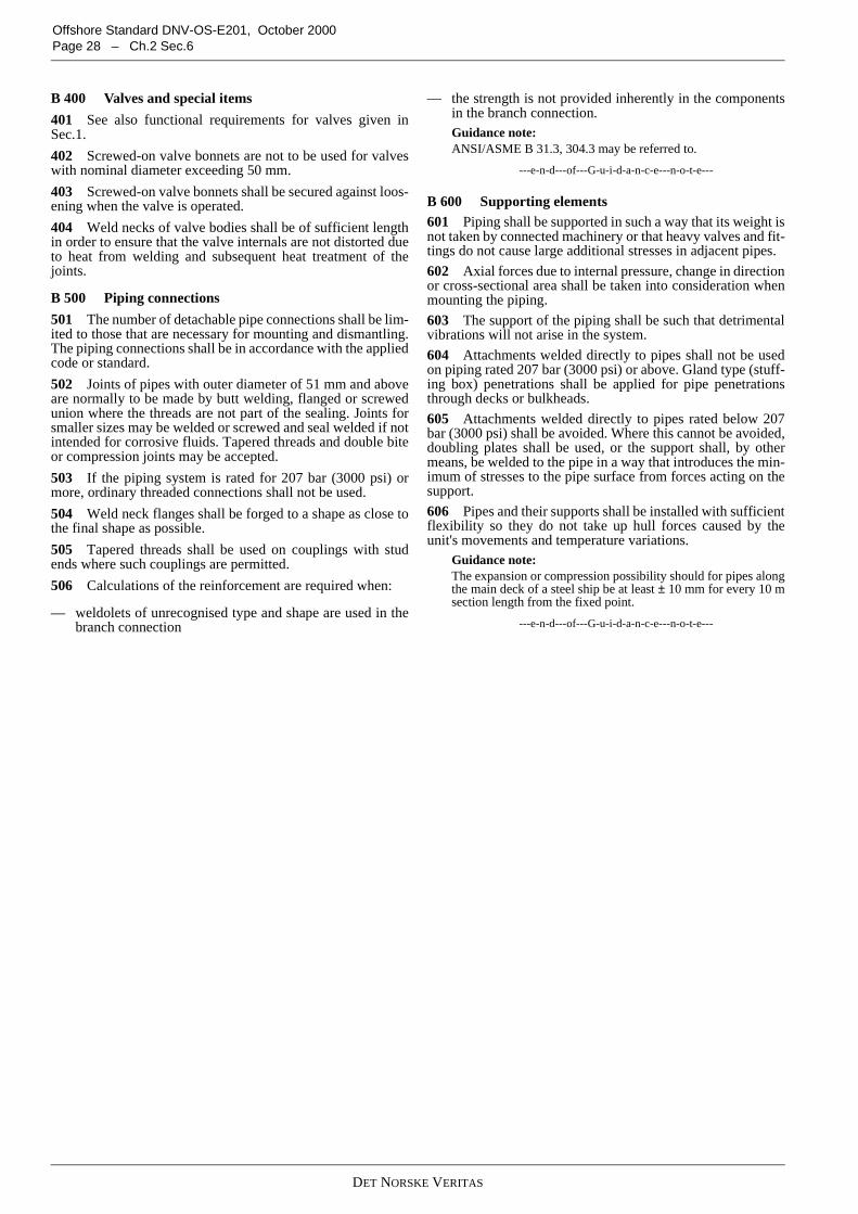
DET NORSKE VERITAS
Offshore Standard DNV-OS-E201, October 2000Page 28 – Ch.2 Sec.6
B 400 Valves and special items
401 See also functional requirements for valves given inSec.1.
402 Screwed-on valve bonnets are not to be used for valveswith nominal diameter exceeding 50 mm.
403 Screwed-on valve bonnets shall be secured against loos-ening when the valve is operated.
404 Weld necks of valve bodies shall be of sufficient lengthin order to ensure that the valve internals are not distorted dueto heat from welding and subsequent heat treatment of thejoints.
B 500 Piping connections
501 The number of detachable pipe connections shall be lim-ited to those that are necessary for mounting and dismantling.The piping connections shall be in accordance with the appliedcode or standard.
502 Joints of pipes with outer diameter of 51 mm and aboveare normally to be made by butt welding, flanged or screwedunion where the threads are not part of the sealing. Joints forsmaller sizes may be welded or screwed and seal welded if notintended for corrosive fluids. Tapered threads and double biteor compression joints may be accepted.
503 If the piping system is rated for 207 bar (3000 psi) ormore, ordinary threaded connections shall not be used.
504 Weld neck flanges shall be forged to a shape as close tothe final shape as possible.
505 Tapered threads shall be used on couplings with studends where such couplings are permitted.
506 Calculations of the reinforcement are required when:
— weldolets of unrecognised type and shape are used in thebranch connection
— the strength is not provided inherently in the componentsin the branch connection.Guidance note:ANSI/ASME B 31.3, 304.3 may be referred to.
---e-n-d---of---G-u-i-d-a-n-c-e---n-o-t-e---
B 600 Supporting elements601 Piping shall be supported in such a way that its weight isnot taken by connected machinery or that heavy valves and fit-tings do not cause large additional stresses in adjacent pipes.
602 Axial forces due to internal pressure, change in directionor cross-sectional area shall be taken into consideration whenmounting the piping.
603 The support of the piping shall be such that detrimentalvibrations will not arise in the system.
604 Attachments welded directly to pipes shall not be usedon piping rated 207 bar (3000 psi) or above. Gland type (stuff-ing box) penetrations shall be applied for pipe penetrationsthrough decks or bulkheads.
605 Attachments welded directly to pipes rated below 207bar (3000 psi) shall be avoided. Where this cannot be avoided,doubling plates shall be used, or the support shall, by othermeans, be welded to the pipe in a way that introduces the min-imum of stresses to the pipe surface from forces acting on thesupport.
606 Pipes and their supports shall be installed with sufficientflexibility so they do not take up hull forces caused by theunit's movements and temperature variations.
Guidance note:The expansion or compression possibility should for pipes alongthe main deck of a steel ship be at least ± 10 mm for every 10 msection length from the fixed point.
---e-n-d---of---G-u-i-d-a-n-c-e---n-o-t-e---
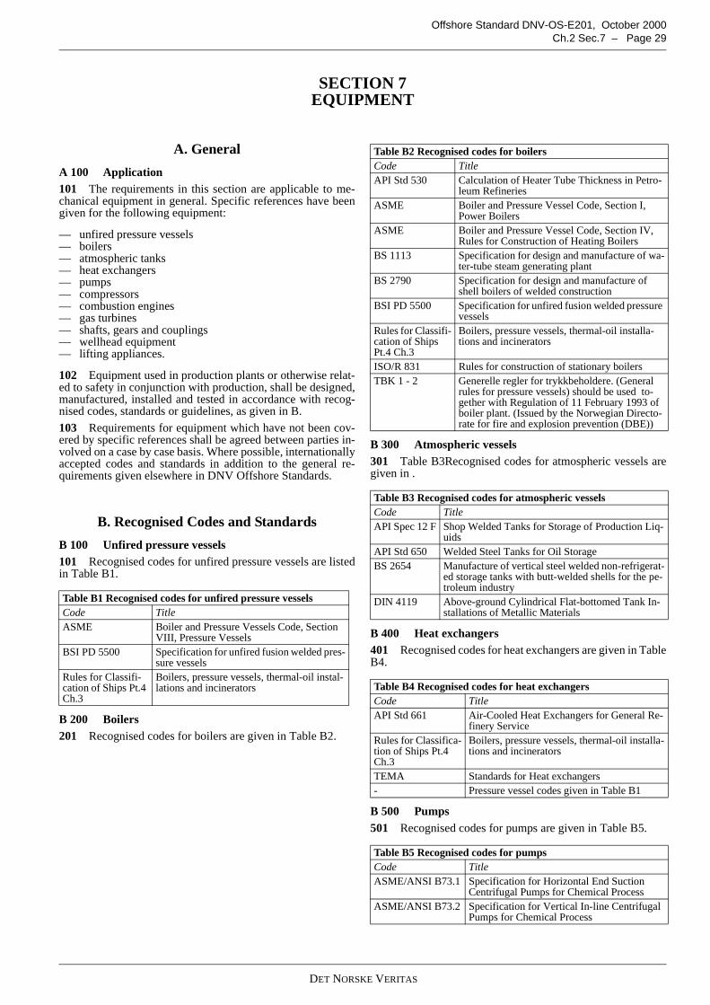
DET NORSKE VERITAS
Offshore Standard DNV-OS-E201, October 2000Ch.2 Sec.7 – Page 29
SECTION 7EQUIPMENT
A. General
A 100 Application101 The requirements in this section are applicable to me-chanical equipment in general. Specific references have beengiven for the following equipment:
— unfired pressure vessels— boilers— atmospheric tanks— heat exchangers— pumps— compressors— combustion engines— gas turbines— shafts, gears and couplings— wellhead equipment— lifting appliances.
102 Equipment used in production plants or otherwise relat-ed to safety in conjunction with production, shall be designed,manufactured, installed and tested in accordance with recog-nised codes, standards or guidelines, as given in B.
103 Requirements for equipment which have not been cov-ered by specific references shall be agreed between parties in-volved on a case by case basis. Where possible, internationallyaccepted codes and standards in addition to the general re-quirements given elsewhere in DNV Offshore Standards.
B. Recognised Codes and Standards
B 100 Unfired pressure vessels101 Recognised codes for unfired pressure vessels are listedin Table B1.
B 200 Boilers201 Recognised codes for boilers are given in Table B2.
B 300 Atmospheric vessels301 Table B3Recognised codes for atmospheric vessels aregiven in .
B 400 Heat exchangers401 Recognised codes for heat exchangers are given in TableB4.
B 500 Pumps501 Recognised codes for pumps are given in Table B5.
Table B1 Recognised codes for unfired pressure vesselsCode TitleASME Boiler and Pressure Vessels Code, Section
VIII, Pressure VesselsBSI PD 5500 Specification for unfired fusion welded pres-
sure vesselsRules for Classifi-cation of Ships Pt.4Ch.3
Boilers, pressure vessels, thermal-oil instal-lations and incinerators
Table B2 Recognised codes for boilersCode TitleAPI Std 530 Calculation of Heater Tube Thickness in Petro-
leum RefineriesASME Boiler and Pressure Vessel Code, Section I,
Power BoilersASME Boiler and Pressure Vessel Code, Section IV,
Rules for Construction of Heating BoilersBS 1113 Specification for design and manufacture of wa-
ter-tube steam generating plantBS 2790 Specification for design and manufacture of
shell boilers of welded constructionBSI PD 5500 Specification for unfired fusion welded pressure
vesselsRules for Classifi-cation of ShipsPt.4 Ch.3
Boilers, pressure vessels, thermal-oil installa-tions and incinerators
ISO/R 831 Rules for construction of stationary boilersTBK 1 - 2 Generelle regler for trykkbeholdere. (General
rules for pressure vessels) should be used to-gether with Regulation of 11 February 1993 ofboiler plant. (Issued by the Norwegian Directo-rate for fire and explosion prevention (DBE))
Table B3 Recognised codes for atmospheric vesselsCode TitleAPI Spec 12 F Shop Welded Tanks for Storage of Production Liq-
uidsAPI Std 650 Welded Steel Tanks for Oil StorageBS 2654 Manufacture of vertical steel welded non-refrigerat-
ed storage tanks with butt-welded shells for the pe-troleum industry
DIN 4119 Above-ground Cylindrical Flat-bottomed Tank In-stallations of Metallic Materials
Table B4 Recognised codes for heat exchangersCode TitleAPI Std 661 Air-Cooled Heat Exchangers for General Re-
finery ServiceRules for Classifica-tion of Ships Pt.4Ch.3
Boilers, pressure vessels, thermal-oil installa-tions and incinerators
TEMA Standards for Heat exchangers- Pressure vessel codes given in Table B1
Table B5 Recognised codes for pumpsCode TitleASME/ANSI B73.1 Specification for Horizontal End Suction
Centrifugal Pumps for Chemical ProcessASME/ANSI B73.2 Specification for Vertical In-line Centrifugal
Pumps for Chemical Process
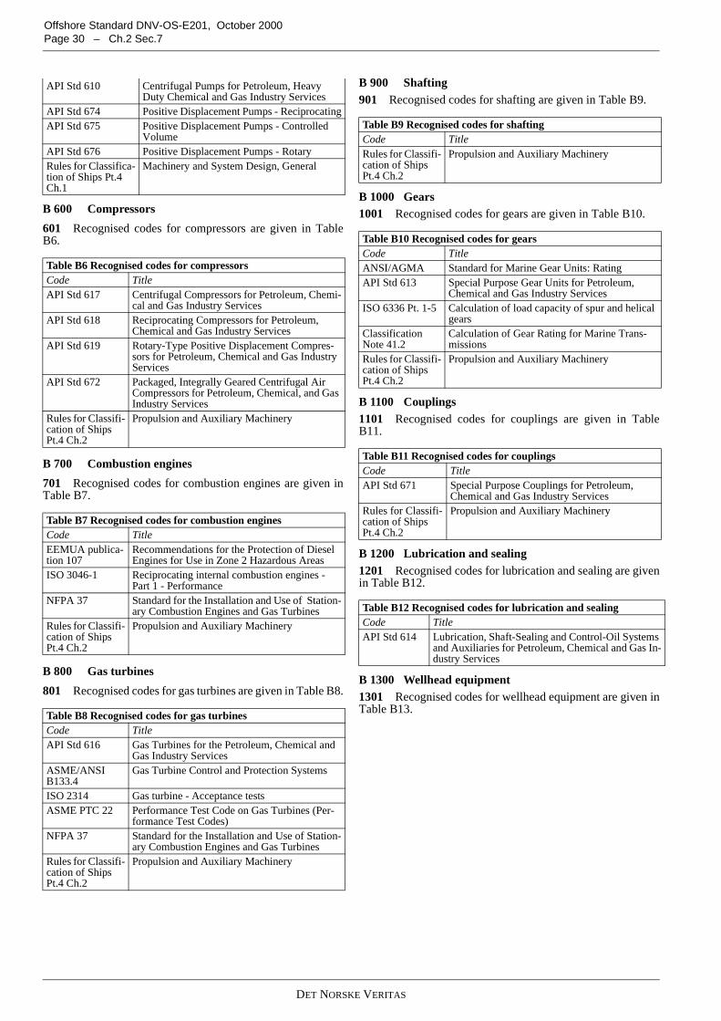
DET NORSKE VERITAS
Offshore Standard DNV-OS-E201, October 2000Page 30 – Ch.2 Sec.7
B 600 Compressors
601 Recognised codes for compressors are given in TableB6.
B 700 Combustion engines
701 Recognised codes for combustion engines are given inTable B7.
B 800 Gas turbines
801 Recognised codes for gas turbines are given in Table B8.
B 900 Shafting901 Recognised codes for shafting are given in Table B9.
B 1000 Gears1001 Recognised codes for gears are given in Table B10.
B 1100 Couplings1101 Recognised codes for couplings are given in TableB11.
B 1200 Lubrication and sealing1201 Recognised codes for lubrication and sealing are givenin Table B12.
B 1300 Wellhead equipment1301 Recognised codes for wellhead equipment are given inTable B13.
API Std 610 Centrifugal Pumps for Petroleum, HeavyDuty Chemical and Gas Industry Services
API Std 674 Positive Displacement Pumps - ReciprocatingAPI Std 675 Positive Displacement Pumps - Controlled
VolumeAPI Std 676 Positive Displacement Pumps - RotaryRules for Classifica-tion of Ships Pt.4Ch.1
Machinery and System Design, General
Table B6 Recognised codes for compressorsCode TitleAPI Std 617 Centrifugal Compressors for Petroleum, Chemi-
cal and Gas Industry ServicesAPI Std 618 Reciprocating Compressors for Petroleum,
Chemical and Gas Industry ServicesAPI Std 619 Rotary-Type Positive Displacement Compres-
sors for Petroleum, Chemical and Gas IndustryServices
API Std 672 Packaged, Integrally Geared Centrifugal AirCompressors for Petroleum, Chemical, and GasIndustry Services
Rules for Classifi-cation of ShipsPt.4 Ch.2
Propulsion and Auxiliary Machinery
Table B7 Recognised codes for combustion enginesCode TitleEEMUA publica-tion 107
Recommendations for the Protection of DieselEngines for Use in Zone 2 Hazardous Areas
ISO 3046-1 Reciprocating internal combustion engines -Part 1 - Performance
NFPA 37 Standard for the Installation and Use of Station-ary Combustion Engines and Gas Turbines
Rules for Classifi-cation of ShipsPt.4 Ch.2
Propulsion and Auxiliary Machinery
Table B8 Recognised codes for gas turbinesCode TitleAPI Std 616 Gas Turbines for the Petroleum, Chemical and
Gas Industry ServicesASME/ANSIB133.4
Gas Turbine Control and Protection Systems
ISO 2314 Gas turbine - Acceptance testsASME PTC 22 Performance Test Code on Gas Turbines (Per-
formance Test Codes)NFPA 37 Standard for the Installation and Use of Station-
ary Combustion Engines and Gas TurbinesRules for Classifi-cation of ShipsPt.4 Ch.2
Propulsion and Auxiliary Machinery
Table B9 Recognised codes for shaftingCode TitleRules for Classifi-cation of ShipsPt.4 Ch.2
Propulsion and Auxiliary Machinery
Table B10 Recognised codes for gearsCode TitleANSI/AGMA Standard for Marine Gear Units: RatingAPI Std 613 Special Purpose Gear Units for Petroleum,
Chemical and Gas Industry ServicesISO 6336 Pt. 1-5 Calculation of load capacity of spur and helical
gearsClassificationNote 41.2
Calculation of Gear Rating for Marine Trans-missions
Rules for Classifi-cation of ShipsPt.4 Ch.2
Propulsion and Auxiliary Machinery
Table B11 Recognised codes for couplingsCode TitleAPI Std 671 Special Purpose Couplings for Petroleum,
Chemical and Gas Industry ServicesRules for Classifi-cation of ShipsPt.4 Ch.2
Propulsion and Auxiliary Machinery
Table B12 Recognised codes for lubrication and sealingCode TitleAPI Std 614 Lubrication, Shaft-Sealing and Control-Oil Systems
and Auxiliaries for Petroleum, Chemical and Gas In-dustry Services

DET NORSKE VERITAS
Offshore Standard DNV-OS-E201, October 2000Ch.2 Sec.7 – Page 31
B 1400 Lifting appliances1401 Recognised codes for lifting appliances are given inTable B14.
Table B13 Recognised codes for wellhead equipmentCode TitleAPI Spec 6A Wellhead and Christmas Tree EquipmentAPI Spec 6FA Fire Test for ValvesAPI Spec 6FC Fire Test for Valve With Automatic BackseatsAPI Spec 6FD Fire Test for Check ValvesAPI RP 14B Design, Installation, Repair and Operation of Sub-
surface Safety Valve SystemsAPI RP 14H Installation, Maintenance and Repair of Surface
Safety Valves and Underwater Safety Valves Off-shore
ISO 10433 Petroleum and Natural Gas Industries - Drilling andProduction Equipment - Specification for WellheadSurface Safety Valves and Underwater SafetyValves for Offshore Service (Based on API Spec14D)
Table B14 Recognised codes for lifting appliancesCode TitleAPI Spec 2C Offshore Cranes
Rules for Certification of Lifting Appliances
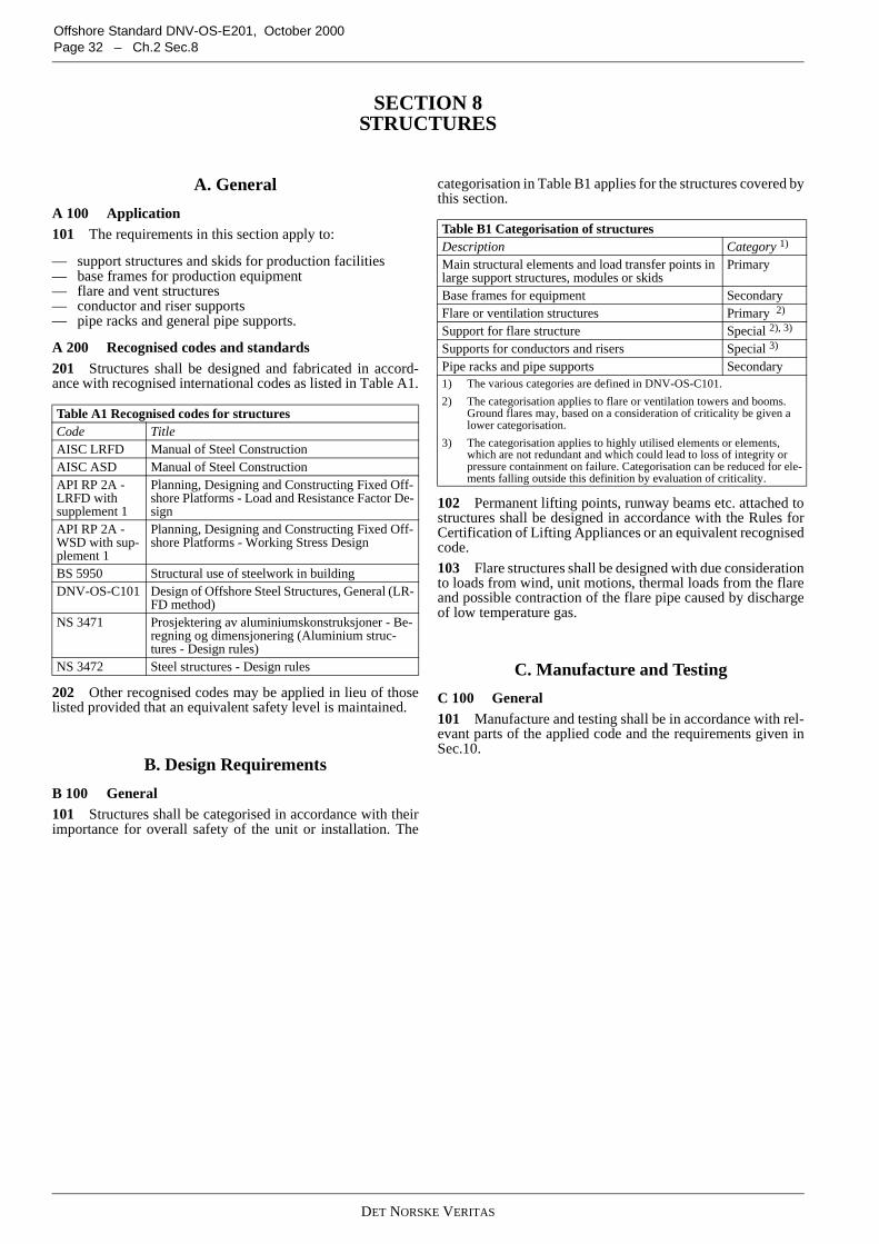
DET NORSKE VERITAS
Offshore Standard DNV-OS-E201, October 2000Page 32 – Ch.2 Sec.8
SECTION 8STRUCTURES
A. General
A 100 Application101 The requirements in this section apply to:
— support structures and skids for production facilities— base frames for production equipment— flare and vent structures— conductor and riser supports— pipe racks and general pipe supports.
A 200 Recognised codes and standards201 Structures shall be designed and fabricated in accord-ance with recognised international codes as listed in Table A1.
202 Other recognised codes may be applied in lieu of thoselisted provided that an equivalent safety level is maintained.
B. Design Requirements
B 100 General101 Structures shall be categorised in accordance with theirimportance for overall safety of the unit or installation. The
categorisation in Table B1 applies for the structures covered bythis section.
102 Permanent lifting points, runway beams etc. attached tostructures shall be designed in accordance with the Rules forCertification of Lifting Appliances or an equivalent recognisedcode.
103 Flare structures shall be designed with due considerationto loads from wind, unit motions, thermal loads from the flareand possible contraction of the flare pipe caused by dischargeof low temperature gas.
C. Manufacture and Testing
C 100 General101 Manufacture and testing shall be in accordance with rel-evant parts of the applied code and the requirements given inSec.10.
Table A1 Recognised codes for structuresCode TitleAISC LRFD Manual of Steel ConstructionAISC ASD Manual of Steel ConstructionAPI RP 2A -LRFD withsupplement 1
Planning, Designing and Constructing Fixed Off-shore Platforms - Load and Resistance Factor De-sign
API RP 2A -WSD with sup-plement 1
Planning, Designing and Constructing Fixed Off-shore Platforms - Working Stress Design
BS 5950 Structural use of steelwork in buildingDNV-OS-C101 Design of Offshore Steel Structures, General (LR-
FD method)NS 3471 Prosjektering av aluminiumskonstruksjoner - Be-
regning og dimensjonering (Aluminium struc-tures - Design rules)
NS 3472 Steel structures - Design rules
Table B1 Categorisation of structuresDescription Category 1)
Main structural elements and load transfer points inlarge support structures, modules or skids
Primary
Base frames for equipment SecondaryFlare or ventilation structures Primary 2)
Support for flare structure Special 2), 3)
Supports for conductors and risers Special 3)
Pipe racks and pipe supports Secondary1) The various categories are defined in DNV-OS-C101.
2) The categorisation applies to flare or ventilation towers and booms.Ground flares may, based on a consideration of criticality be given alower categorisation.
3) The categorisation applies to highly utilised elements or elements,which are not redundant and which could lead to loss of integrity orpressure containment on failure. Categorisation can be reduced for ele-ments falling outside this definition by evaluation of criticality.
DET NORSKE VERITAS
Offshore Standard DNV-OS-E201, October 2000Ch.2 Sec.9 – Page 33
SECTION 9MATERIALS AND CORROSION PROTECTION
A. General
A 100 Objective
101 This section provides requirements for materials andcorrosion protection applicable to hydrocarbon productionsystems and associated structures.
B. Principles
B 100 General
101 Selection of materials shall be based on type and level ofstresses, temperatures, corrosive and erosive conditions, con-sequences and possibilities of failure associated with installa-tion, operation and maintenance.
102 The materials selected shall be suitable for the purposeand have adequate properties of strength and ductility. Materi-als incorporated in any portion of a system which are critical tothe integrity and safety shall have good weldability propertiesfor manufacture and installation, if welding shall be per-formed. Materials shall be corrosion resistant or protectedagainst corrosion where this is deemed necessary.
103 Non-combustible materials shall be used. Where any re-quired property does not permit the use of such material, alter-native materials may be used subject to agreement.
104 For selection of acceptable materials suitable for H2Scontaminated products (sour service), see ANSI/NACEMR0175.
C. Specific Requirements
C 100 Materials for pressure vessels, piping and equip-ment
101 Materials for equipment and piping shall be in accord-ance with the requirements given by the referred recognisedcodes.
C 200 Materials for load-carrying parts
201 For welded C-Mn steels for major load-carrying partsthe chemical composition is normally to be limited to the fol-lowing carbon (C)- and carbon equivalent (CE)-values:
—
—
When the elements in the following formula are known, thefollowing carbon equivalent formula shall be used:
202 Materials not meeting this limitation may be used sub-ject to suitable welding procedures in each case. The weldingof such materials normally requires more stringent fabricationprocedures regarding selection of consumables, preheating andpost weld heat treatment, see Sec.10.
203 Impact testing is required for steel materials with refer-ence thickness above 6 mm, if the minimum design tempera-ture (MDT) is below 0 °C. These materials shall meet Charpy
V-notch energy values of minimum 34 J at MDT. For test pro-cedures and requirements, see DNV-OS-B101.
204 If equipment is required to be designed against sulphidestress corrosion cracking, the hardness of any part of materialand welds for ferritic steels is not to exceed 260 HV5 in the fi-nal heat treated condition. For other steel materials, see ANSI/NACE MR0175, concerning allowable hardness.
205 Plates that transfer significant loads in the thickness di-rection of the plate shall be documented with through thicknessductility in order to reduce the probability of lamellar tearing.The minimum reduction of area, Zz, is not to be less than 25 %.
C 300 Rolled steel
301 The material standard or specification has to define anextent of testing comparable to that described in DNV-OS-B101.
C 400 Steel forgings
401 The material standard or specification has to define anextent of testing comparable to that described DNV-OS-B101.
402 Flanges, valve bodies, etc., are normally to be forged toshape or cast. If these components are manufactured fromforged bar stock, rolled bar stock, forged plate or rolled plate,the material shall be tested in the transverse direction and is tomeet the requirements for longitudinal specimens of forged toshape components. If using plate, testing is also to be carriedout in the short-transverse (through thickness) direction.
C 500 Steel and iron castings
501 The material standard or specification shall define an ex-tent of testing comparable to that described DNV-OS-B101.
502 Iron castings shall not to be used for critical parts withminimum design temperature below 0 °C.
C 600 Aluminium, copper and other non-ferrous alloys
601 Aluminium, copper and other non-ferrous alloys shallhave a supply condition, chemical composition, mechanicalproperties, weldability and soundness as described in DNV-OS-B101.
Other standards giving comparable parameters may be usedupon special agreement.
C 700 Bolts and nuts
701 Bolts and nuts considered as essential for structural andoperational safety shall conform to a recognised standard, e.g.ISO 898.
702 Major pressure retaining or structural bolts and nuts withspecified minimum yield stress above 490 N/mm2 shall bemade of alloy steel, i.e. (% Cr + % Mo + % Ni) = 0.50 and sup-plied in the quenched and tempered condition.
703 For general service, the specified tensile properties arenot to exceed ISO 898 property Class 10.9 when the installa-tion is in atmospheric environment. For equipment submergedin seawater, the tensile properties are not to exceed propertyclass 8.8 or equivalent.
Guidance note:For bolted joints to be part of equipment designed for sulphidestress cracking service, lower tensile properties than for 8,8 classmay be necessary in order to comply with ANSI/NACEMR0175.
---e-n-d---of---G-u-i-d-a-n-c-e---n-o-t-e---
C 0.22 %≤
CEa CMn6
-------- 0.04 0.45C %≤+ +=
CE b� � CMn6
-------- Cr Mo V+ +5
-------------------------------- Cu Ni+15
-------------------- 0.45≤+ + +=
DET NORSKE VERITAS
Offshore Standard DNV-OS-E201, October 2000Page 34 – Ch.2 Sec.9
C 800 Sealing materials and polymers
801 The materials to be used shall be suitable for the intend-ed service and are to be capable of sustaining the specified op-erating pressure and temperature of the particular unit or fluid.
D. Material Certificates
D 100 General
101 All materials for major load-bearing and pressure con-taining components and load carrying parts shall be furnishedwith documentation stating process of manufacture and heattreatment (metallic materials) together with results of relevantproperties obtained through appropriate tests carried out in ac-cordance with recognised standards.
Guidance note:The following mechanical properties should normally be testedand recorded on a material certificate:
— ultimate tensile strength and yield strength— elongation and reduction of area— Charpy V-notch impact toughness— hardness, where applicable e.g. for sour service— through thickness properties, where applicable.
---e-n-d---of---G-u-i-d-a-n-c-e---n-o-t-e---
D 200 Type of document
201 Material certificate types shall be as given in Table D1.
202 Test certificate shall be required for:
— plates for boilers and steam heated equipment— plates for pressure vessels with thickness t > 38 mm— cast iron and cast steel for use at temperature T > 400 °C
or pD > 2000 where p = pressure in bar, D = diameter inmm.
203 Works certificate shall be required for:
— materials for pressure containing and major load carryingcomponents which are not included in 202.
204 Test report shall be acceptable for other equipment.
E. Corrosion Protection
E 100 General
101 Equipment and piping shall be corrosion resistant orprotected against corrosion where considered necessary forsafety or operational reasons.
Guidance note:Unprotected carbon steel and stainless steel materials are not tobe used for seawater service except for high molybdenum stain-less steel or equivalent.
---e-n-d---of---G-u-i-d-a-n-c-e---n-o-t-e---
Corrosion allowance of low alloy carbon steel shall be depend-ent on corrosivity of commodity, lifetime of equipment andcorrosion control method used.
Guidance note:Corrosion allowance in Table E1 is given as guidance.
---e-n-d---of---G-u-i-d-a-n-c-e---n-o-t-e---
102 Dissimilar metallic materials in contact shall be avoidedor adequately protected against galvanic corrosion.
103 External steel surfaces exposed to the marine atmos-phere and splash zone shall be protected by coating. Specialmetallic materials may be used.
104 Steel components submerged in seawater shall be exter-nally protected by cathodic protection or a combination of ca-thodic protection and coating.
105 Internal corrosion control shall be used if the commoditycontains water or has a relative humidity, of more than 50 %and if the partial pressure of corrosive gases is above the fol-lowing limits:
— oxygen: 100 Pa— hydrogen sulphide: 10 kPa— carbon dioxide: 20 kPa
Increased corrosivity due to combination of gases shall be con-sidered.
106 Inhibitors shall be selected when relevant to suit the ac-tual internal environment.
107 Corrosion monitoring shall be used where considerednecessary.
F. Erosion
F 100 General
101 Precautions shall be taken to monitor and avoid erosionin process piping and equipment.
Table D1 Material certificationCertification process ISO 10474
(EN 10204)Test reportConfirmation by the manufacturer that the suppliedproducts fulfil the purchase specification, and testdata from regular production, not necessarily fromproducts supplied
2.2
Work certificateTest results of all specified tests from samples takenfrom the products supplied. Inspection and tests wit-nessed and signed by QA department
3.1.B
Test certificateAs work certificate, inspection and tests witnessedand signed by an independent third party body
3.1.C
Table E1 Corrosion allowance “c” for steel materialsService 1) 2) c (mm)Saturated steam 0.8Steam coils 2Feedwater and blowdown pipes (for boilers) 1.5Compressed air 1.0Hydraulic oil 0.3Lubricating oil 0.3Fuel oil 1Refrigerants 0.3Fresh water 0.8Hydrocarbon service 2Mud or cement 31) An additional allowance for external corrosion shall be consid-
ered according to the figures given in the Table, depending on theexternal medium
2) Where efficient protective methods against corrosion are used,the corrosion allowance may be reduced up to 50 %
DET NORSKE VERITAS
Offshore Standard DNV-OS-E201, October 2000Ch.2 Sec.10 – Page 35
SECTION 10MANUFACTURE, WORKMANSHIP AND TESTING
A. General
A 100 Application
101 This section covers equipment, structures and systemsduring fabrication, installation and final testing onboard.
A 200 Quality assurance and quality control
201 The manufacturer shall have the necessary productionfacilities, qualifications, procedures and personnel to ensurethat the product will be manufactured to the specified require-ments.
A 300 Marking
301 All equipment shall be clearly marked with identifica-tion and serial number, relating the equipment to certificatesand fabrication documentation.
Guidance note:Low stress stamping may be required for certain materials. Paintmarkings may be acceptable, but care must be exercised duringhandling and storage to preserve the identification.
---e-n-d---of---G-u-i-d-a-n-c-e---n-o-t-e---
B. Manufacture
B 100 Welder's qualification
101 Welding of pressure containing components and pipingsystems and welding of load carrying equipment and structuresshall be carried out by certified welders, only.
102 The manufacturer shall supply each welder with an iden-tification number or symbol to enable identification of thework carried out by each particular welder.
B 200 Welding
201 All welding as specified in 101 shall be performed in ac-cordance with an approved welding procedure specification(WPS).
202 A welding procedure qualification test (WPQT) may berequired when makers intend to use welding procedure speci-fication (WPS) for which there exists insufficient experience atplant or elsewhere or if new complicated structural details areused. For details of performance of WPQT, limitations etc. seeDNV-OS-C401 or the applied design and fabrication code.
203 Butt welded joints shall be of the full penetration type.
204 If supports and similar non-pressure parts are welded di-rectly to pressure retaining parts, the welding requirements forthe pressure retaining parts shall be adhered to.
205 Repair welding is normally to be carried out with elec-trodes giving a weld deposit compatible with the parent mate-rial.
B 300 Heat treatment
301 The component shall be heat treated after forming and/or welding if required by the applied code or standard or iffound necessary to maintain adequate notch ductility and toavoid hydrogen induced cracking.
302 Rate of heating and cooling, hold time and metal tem-perature shall be properly recorded.
303 A normalising heat treatment is required for hot-formedparts, unless the process of hot forming has been carried out
within the appropriate temperature range, duration and coolingrate.
304 The heat treatment for cold-worked materials shall beselected with respect to the degree of plastic deformation in thematerial.
305 Preheating and/or post weld heat treatment shall be usedwhen necessitated by the dimensions and material composi-tion.
306 Post weld heat treatment (PWHT) is normally to be per-formed in a fully enclosed furnace. Local PWHT may be per-formed on simple joints when following an approvedprocedure.
307 In case of defects being revealed after heat treatment,new heat treatment shall normally be carried out after repairwelding of the defects.
B 400 Pipe bending
401 The bending procedure shall be such that the flatteningof the pipe cross section and wall thinning are within accepta-ble tolerances specified in the applied code and standard.
C. Non-destructive Testing (NDT)
C 100 General
101 The extent of NDT shall be in accordance with the codeor standard accepted for design and fabrication, except as spec-ified in 102.
102 The minimum extent of NDT shall be in accordancewith the requirements given in Table C1.
103 The acceptance criteria shall be in accordance with thecode or standard accepted for design and fabrication.
104 Ultrasonic examination may be used in lieu of radiogra-phy where practicable and where radiography does not givedefinitive results.
Table C1 Extent of non-destructive testing of welds for pressurecontaining components and piping
Limitations Weldtype 4)
Visual in-spection,see 106
Radiogra-phy, see104
Magneticparticle, see105
up to 150#ratingand 185 °C 1)
L 100 % 10 % 10 %C 100 % 5 % 5 %B 100 % - 10 %
300# rating 2)L 100 % 20 % 20 %C 100 % 10 % 10 %B 100 % - 100 %
over 300#rating 3)
L 100 % 100 % 100 %C 100 % 100 % 100 %B 100 % - 100 %
1) Piping and components for non-flammable, non-toxic utility service.Pressure rating up to 150 lbs (PN 20). Upper temperature limit 185 °C
2) Process and utility piping up to pressure rating 300 lbs (PN 50)
3) Process and utility piping with pressure rating above 300 lbs (PN 50) orsubject to severe cyclic loading. (See ANSI B31.3 para. 300.2 for defi-nition of severe cyclic loading)
4) L = Longitudinal weld, including intersection between L and CC = Circumferential, stub-in or butt weldB = Fillet weld e.g. for outlets, reinforcement rings etc.
DET NORSKE VERITAS
Offshore Standard DNV-OS-E201, October 2000Page 36 – Ch.2 Sec.10
105 Magnetic particle inspection is the preferred method fordetection of surface defects. For non-magnetic materials, liq-uid penetrant method shall be used.
106 Visual inspection of fabricated components, spools etc.shall cover both fabrication, welding, erection and assembly.The inspection points to be covered during fabrication, erec-tion and assembly shall be defined in the client’s proceduresand shall be sufficiently extensive to ensure that code require-ments and design intent are incorporated during fabricatione.g. fit-up, flange alignment, welding parameters, weld profile,supports and bolt tightening.
107 NDT required by Table C1 shall be carried out in ac-cordance with recognised NDT standards, by qualified opera-tors.
108 When post weld heat treatment is required, the finalNDT should normally be performed after heat treatment.
109 The final NDT shall be performed before any possibleprocess that would make the required NDT impossible orwould have erroneous results as a consequence (e.g. coating ofsurfaces).
110 All performed examination and results shall be recordedin a systematic way allowing traceability.
111 In addition to above, if the carbon equivalent, see Sec.9C200, exceeds 0.45 for the actual material, a 100 % magneticparticle examination shall be carried out during the initialphase of production to prove absence of surface cracks.
C 200 Structures
201 Non-destructive testing of structures shall be in accord-ance with relevant parts of the applied code, see Sec.8 and thissection.
D. Testing
D 100 Testing of weld samples
101 Mechanical testing of weldments shall be carried out bycompetent personnel and in accordance with the applied codeor standard.
102 Weldments of piping and equipment used for H2S con-taminated fluids shall be tested for hardness in accordance withANSI/NACE MR0175.
D 200 Pressure testing and cleaning
201 Pressure containing piping and components shall be sub-ject to a hydrostatic pressure test in accordance with appliedcodes and standards.
202 The test pressure shall be determined by the workingpressure, and shall minimum be 1.5 x the maximum workingpressure if not otherwise specified in the applied codes orstandards.
203 The holding time shall be minimum 15 minutes, or asdefined in the applied codes or standards. The time must be ofsufficient length to allow for thorough visual examinationwhen the pressure has stabilised.
204 The pressure and holding time shall be recorded anddocumented in a systematic way allowing traceability, e.g.with a calibrated chart recorder.
205 If hydrostatic pressure testing of piping represents par-ticular problems, alternative methods of testing may be ap-plied.
206 Nominal stresses are in no case to exceed 90 % of theminimum specified yield strength of the material.
207 Piping systems shall be cleaned (e.g. by flushing, retro-jetting, chemical cleaning etc.) to remove debris or foreignbodies prior to start-up of sensitive equipment such as pumps,compressors, isolation valves etc.
D 300 Load testing301 Lifting appliances rated below 20 tonnes shall be loadtested after installation onboard with 25 % in excess of the safeworking load (SWL), in accordance with a written test pro-gram.
302 Flare booms for well testing and work-over shall be test-ed after installation with an overload of 25 % related to the re-quired weight of burner and spreader. This overload test is todemonstrate that the boom is capable of carrying out the mo-tions such as slewing, hoisting etc., as relevant.
D 400 Functional testing401 All systems, including associated control, monitoringand safety systems shall be tested as far as possible prior to in-troduction of hydrocarbons.
Guidance note:The objective is to prove the functionality of all systems requiredfor safe commissioning of the plant.
---e-n-d---of---G-u-i-d-a-n-c-e---n-o-t-e---
402 Tests shall as a minimum include adjustment of control-lers, calibration of sensors and alarms, function and timing ofshutdown and blowdown valves and function testing of protec-tion systems.
403 Testing of protection systems for process and utility sys-tems and for safety critical equipment shall be in accordancewith written test programmes.
404 The status of tests shall be recorded in an auditable man-ner and a system to control status of remedial and outstandingwork shall be established.
405 Tests shall simulate operating conditions as far as prac-ticable and shall cover all levels of shutdowns.
406 Shortly after introduction of hydrocarbons, a final testprogramme shall be carried out where the functionality of es-sential elements of protection systems is proven under operat-ing conditions.
Guidance note:The final ‘hot test’ will typically take place 2 to 4 weeks afterstart-up of production, after the production plant has been com-missioned.It should cover any tests that were not possible to carry out priorto introduction of hydrocarbons, e.g. function test of de-pressur-ing system. It will also cover the various staged shutdown levelsand include timing of shutdown valves.
---e-n-d---of---G-u-i-d-a-n-c-e---n-o-t-e---

DET NORSKE VERITAS
Veritasveien 1, N-1322 Høvik, Norway Tel.: +47 67 57 99 00 Fax: +47 67 57 99 11
OFFSHORE STANDARDDNV-OS-E201
HYDROCARBON PRODUCTION PLANT
CHAPTER 3
CERTIFICATION AND CLASSIFICATION
CONTENTS PAGE
Sec. 1 Certification and Classification................................................................................................ 39Sec. 2 Design Review ......................................................................................................................... 40Sec. 3 Certification of Equipment ...................................................................................................... 41Sec. 4 Survey during Construction ..................................................................................................... 44Sec. 5 Surveys at Commissioning and Start-up .................................................................................. 45

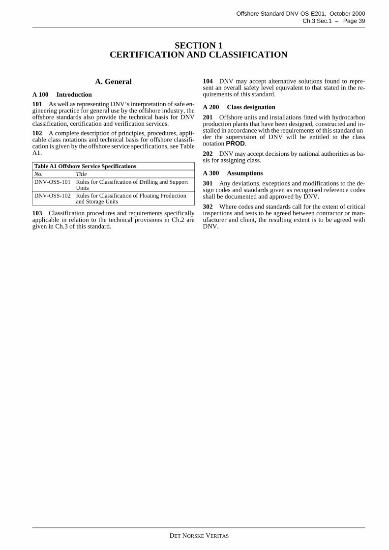
DET NORSKE VERITAS
Offshore Standard DNV-OS-E201, October 2000Ch.3 Sec.1 – Page 39
SECTION 1CERTIFICATION AND CLASSIFICATION
A. General
A 100 Introduction
101 As well as representing DNV’s interpretation of safe en-gineering practice for general use by the offshore industry, theoffshore standards also provide the technical basis for DNVclassification, certification and verification services.
102 A complete description of principles, procedures, appli-cable class notations and technical basis for offshore classifi-cation is given by the offshore service specifications, see TableA1.
103 Classification procedures and requirements specificallyapplicable in relation to the technical provisions in Ch.2 aregiven in Ch.3 of this standard.
104 DNV may accept alternative solutions found to repre-sent an overall safety level equivalent to that stated in the re-quirements of this standard.
A 200 Class designation
201 Offshore units and installations fitted with hydrocarbonproduction plants that have been designed, constructed and in-stalled in accordance with the requirements of this standard un-der the supervision of DNV will be entitled to the classnotation PROD.
202 DNV may accept decisions by national authorities as ba-sis for assigning class.
A 300 Assumptions
301 Any deviations, exceptions and modifications to the de-sign codes and standards given as recognised reference codesshall be documented and approved by DNV.
302 Where codes and standards call for the extent of criticalinspections and tests to be agreed between contractor or man-ufacturer and client, the resulting extent is to be agreed withDNV.
Table A1 Offshore Service SpecificationsNo. TitleDNV-OSS-101 Rules for Classification of Drilling and Support
UnitsDNV-OSS-102 Rules for Classification of Floating Production
and Storage Units
DET NORSKE VERITAS
Offshore Standard DNV-OS-E201, October 2000Page 40 – Ch.3 Sec.2
SECTION 2DESIGN REVIEW
A. General
A 100 Application
101 This section lists design related requirements for certifi-cation or classification.
B. Specific Requirements for Certification orClassification
B 100 General
101 The following requirements shall be applied in conjunc-tion with the technical requirements in Ch.2 of this standardwhen used for certification or classification purposes.
B 200 Design principles
201 Ch.2 Sec.1:
1) Structures, equipment and systems outside the boundariesstated in Sec.1 A100, such as wellhead equipment, buoyswith riser connections to seabed and export lines for crudeoil and gas may be covered to the extent and according torules and/or standards specified in the agreement for clas-sification.
2) If requirements of applicable governmental regulationsare incompatible with the requirements of this standard,the regulations will take precedence.
B 300 Electrical, instrumentation and control systems
301 Ch.2 Sec.5:
1) Other codes and standards such as IEEE, API, IEC, BS orsimilar may be applied upon consideration in each case.
Guidance note:Such agreement may be given if it is demonstrated that implica-tions for personnel and plant safety are insignificant. The clientis to forward a detailed application where the systems affectedare listed and where deviations between the various codes areidentified. Any implications for personnel and plant safety, oper-ation and maintenance shall be evaluated.
---e-n-d---of---G-u-i-d-a-n-c-e---n-o-t-e---
2) The failure mode shall be agreed with DNV on a case bycase basis.
B 400 Piping
401 Ch.2 Sec.6:
1) Piping parts that are covered by recognised standards andhave a complicated configuration that makes theoreticalcalculations unreliable may be accepted based on certifiedprototype proof test reports. Prototype test methods andacceptance criteria shall be agreed with DNV.
2) Not welded valves designed, fabricated and tested accord-ing to recognised standards will be accepted based on themanufacturer's certification.
3) Special valves constructed by welding and of 600 lbs (PN100) flange rating and above are subjected to design veri-fication and inspection.
4) Special items not covered by recognised standards shall beapproved for their intended use. Drawings shall be submit-ted for approval and shall be supported by stress calcula-tions. Application, type of medium, design pressure,temperature range, materials and other design parametersshall be given.
5) Special items not covered by recognised standards havinga complicated configuration that makes theoretical calcu-lations unreliable may be accepted based on certified pro-totype proof test reports that prove their suitability for theintended use.
B 500 Materials and corrosion protection501 Ch.2 Sec.9:
1) A104: The use of alternative materials shall be approvedby DNV.
2) A105: Modified material compositions and propertiesshall be documented in specifically written specificationsthat shall be submitted for approval in each case.
3) B502: Position and orientation of steel forging test sam-ples shall be agreed with DNV.
4) B701: Alternative standards for aluminium, copper andnon-ferrous alloys shall be agreed with DNV.
B 600 Manufacture, workmanship and testing601 Ch.2 Sec.10:
1) Welding repairs shall be performed according to an ap-proved repair procedure.
2) If the required NDT reveals a defect requiring repair, ad-ditional testing shall be carried out at the discretion of thesurveyor in accordance with the applied code or standard.
3) Testing of protection systems for process and utility sys-tems and for safety critical equipment shall be in accord-ance with written test programmes accepted by DNV.
4) Shortly after introduction of hydrocarbons, a final test pro-gramme shall be carried out where the functionality of es-sential elements of protection systems is proven underoperating conditions. The programme shall be accepted byDNV.
C. Documentation Requirements
C 100 General101 Documentation on design and fabrication shall be in ac-cordance with DNV-RP-A201 and DNV-RP-A202.
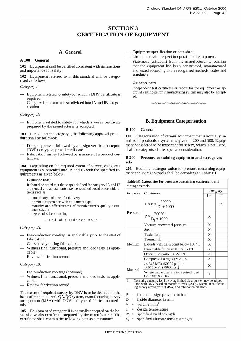
DET NORSKE VERITAS
Offshore Standard DNV-OS-E201, October 2000Ch.3 Sec.3 – Page 41
SECTION 3CERTIFICATION OF EQUIPMENT
A. General
A 100 General
101 Equipment shall be certified consistent with its functionsand importance for safety.
102 Equipment referred to in this standard will be catego-rised as follows:
Category I:
— Equipment related to safety for which a DNV certificate isrequired.
— Category I equipment is subdivided into IA and IB catego-risation.
Category II:
— Equipment related to safety for which a works certificateprepared by the manufacturer is accepted.
103 For equipment category I, the following approval proce-dure shall be followed:
— Design approval, followed by a design verification report(DVR) or type approval certificate.
— Fabrication survey followed by issuance of a product cer-tificate.
104 Depending on the required extent of survey, category Iequipment is subdivided into IA and IB with the specified re-quirements as given below.
Guidance note:It should be noted that the scopes defined for category IA and IBare typical and adjustments may be required based on considera-tions such as:
- complexity and size of a delivery- previous experience with equipment type- maturity and effectiveness of manufacturer’s quality assur-
ance system- degree of subcontracting.
---e-n-d---of---G-u-i-d-a-n-c-e---n-o-t-e---
Category IA:
— Pre-production meeting, as applicable, prior to the start offabrication.
— Class survey during fabrication.— Witness final functional, pressure and load tests, as appli-
cable.— Review fabrication record.
Category IB:
— Pre-production meeting (optional).— Witness final functional, pressure and load tests, as appli-
cable.— Review fabrication record.
The extent of required survey by DNV is to be decided on thebasis of manufacturer's QA/QC system, manufacturing surveyarrangement (MSA) with DNV and type of fabrication meth-ods
105 Equipment of category II is normally accepted on the ba-sis of a works certificate prepared by the manufacturer. Thecertificate shall contain the following data as a minimum:
— Equipment specification or data sheet.— Limitations with respect to operation of equipment.— Statement (affidavit) from the manufacturer to confirm
that the equipment has been constructed, manufacturedand tested according to the recognised methods, codes andstandards.
Guidance note:
Independent test certificate or report for the equipment or ap-proval certificate for manufacturing system may also be accept-ed.
---e-n-d---of---G-u-i-d-a-n-c-e---n-o-t-e---
B. Equipment Categorisation
B 100 General
101 Categorisation of various equipment that is normally in-stalled in production systems is given in 200 and 300. Equip-ment considered to be important for safety, which is not listed,shall be categorised after special consideration.
B 200 Pressure containing equipment and storage ves-sels
201 Equipment categorisation for pressure containing equip-ment and storage vessels shall be according to Table B1.
P = internal design pressure in barDi = inside diameter in mmV = volume in m3
T = design temperatureσy = specified yield strengthσt = specified ultimate tensile strength
Table B1 Categories for pressure containing equipment andstorage vessels
Property ConditionsCategory
I 1) II
Pressure
X
X
Vacuum or external pressure X
Medium
Steam XToxic fluid XThermal oil XLiquids with flash point below 100 °C XFlammable fluids with T > 150 °C XOther fluids with T > 220 °C XCompressed air/gas PV ≥ 1.5 X
Material
σy 345 MPa (50000 psi) orσt 515 MPa (75000 psi) X
Where impact testing is required. SeeCh.2 Sec.9 C203. X
1) Normally category IA, however, limited class survey may be agreedupon with DNV based on manufacturer's QA/QC system, manufactur-ing survey arrangement (MSA) and fabrication methods.
1 P20000
Di 1000+------------------------≤<
P20000
Di 1000+------------------------>
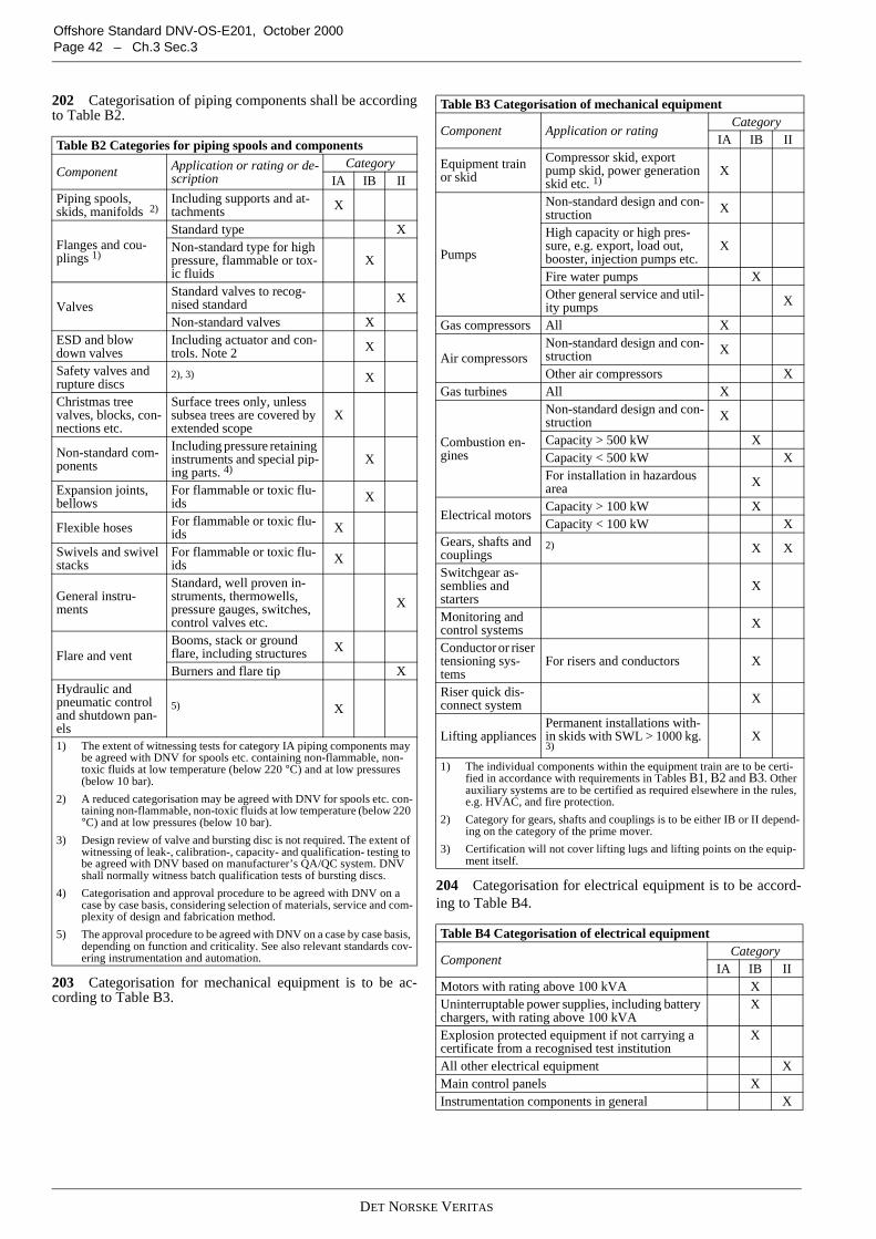
DET NORSKE VERITAS
Offshore Standard DNV-OS-E201, October 2000Page 42 – Ch.3 Sec.3
202 Categorisation of piping components shall be accordingto Table B2.
203 Categorisation for mechanical equipment is to be ac-cording to Table B3.
204 Categorisation for electrical equipment is to be accord-ing to Table B4.
Table B2 Categories for piping spools and components
Component Application or rating or de-scription
CategoryIA IB II
Piping spools,skids, manifolds 2)
Including supports and at-tachments X
Flanges and cou-plings 1)
Standard type XNon-standard type for highpressure, flammable or tox-ic fluids
X
ValvesStandard valves to recog-nised standard X
Non-standard valves XESD and blowdown valves
Including actuator and con-trols. Note 2 X
Safety valves andrupture discs
2), 3) X
Christmas treevalves, blocks, con-nections etc.
Surface trees only, unlesssubsea trees are covered byextended scope
X
Non-standard com-ponents
Including pressure retaininginstruments and special pip-ing parts. 4)
X
Expansion joints,bellows
For flammable or toxic flu-ids X
Flexible hoses For flammable or toxic flu-ids X
Swivels and swivelstacks
For flammable or toxic flu-ids X
General instru-ments
Standard, well proven in-struments, thermowells,pressure gauges, switches,control valves etc.
X
Flare and ventBooms, stack or groundflare, including structures X
Burners and flare tip XHydraulic andpneumatic controland shutdown pan-els
5) X
1) The extent of witnessing tests for category IA piping components maybe agreed with DNV for spools etc. containing non-flammable, non-toxic fluids at low temperature (below 220 °C) and at low pressures(below 10 bar).
2) A reduced categorisation may be agreed with DNV for spools etc. con-taining non-flammable, non-toxic fluids at low temperature (below 220°C) and at low pressures (below 10 bar).
3) Design review of valve and bursting disc is not required. The extent ofwitnessing of leak-, calibration-, capacity- and qualification- testing tobe agreed with DNV based on manufacturer’s QA/QC system. DNVshall normally witness batch qualification tests of bursting discs.
4) Categorisation and approval procedure to be agreed with DNV on acase by case basis, considering selection of materials, service and com-plexity of design and fabrication method.
5) The approval procedure to be agreed with DNV on a case by case basis,depending on function and criticality. See also relevant standards cov-ering instrumentation and automation.
Table B3 Categorisation of mechanical equipment
Component Application or ratingCategory
IA IB II
Equipment trainor skid
Compressor skid, exportpump skid, power generationskid etc. 1)
X
Pumps
Non-standard design and con-struction X
High capacity or high pres-sure, e.g. export, load out,booster, injection pumps etc.
X
Fire water pumps XOther general service and util-ity pumps X
Gas compressors All X
Air compressorsNon-standard design and con-struction X
Other air compressors XGas turbines All X
Combustion en-gines
Non-standard design and con-struction X
Capacity > 500 kW XCapacity < 500 kW XFor installation in hazardousarea X
Electrical motorsCapacity > 100 kW XCapacity < 100 kW X
Gears, shafts andcouplings
2) X X
Switchgear as-semblies andstarters
X
Monitoring andcontrol systems X
Conductor or risertensioning sys-tems
For risers and conductors X
Riser quick dis-connect system X
Lifting appliancesPermanent installations with-in skids with SWL > 1000 kg.3)
X
1) The individual components within the equipment train are to be certi-fied in accordance with requirements in Tables B1, B2 and B3. Otherauxiliary systems are to be certified as required elsewhere in the rules,e.g. HVAC, and fire protection.
2) Category for gears, shafts and couplings is to be either IB or II depend-ing on the category of the prime mover.
3) Certification will not cover lifting lugs and lifting points on the equip-ment itself.
Table B4 Categorisation of electrical equipment
ComponentCategory
IA IB IIMotors with rating above 100 kVA XUninterruptable power supplies, including batterychargers, with rating above 100 kVA
X
Explosion protected equipment if not carrying acertificate from a recognised test institution
X
All other electrical equipment XMain control panels XInstrumentation components in general X
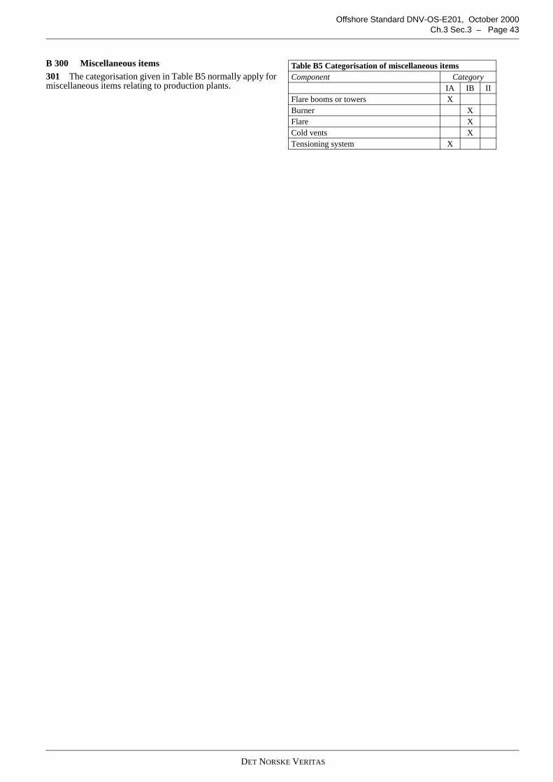
DET NORSKE VERITAS
Offshore Standard DNV-OS-E201, October 2000Ch.3 Sec.3 – Page 43
B 300 Miscellaneous items301 The categorisation given in Table B5 normally apply formiscellaneous items relating to production plants.
Table B5 Categorisation of miscellaneous itemsComponent Category
IA IB IIFlare booms or towers XBurner XFlare XCold vents XTensioning system X

DET NORSKE VERITAS
Offshore Standard DNV-OS-E201, October 2000Page 44 – Ch.3 Sec.4
SECTION 4SURVEY DURING CONSTRUCTION
A. General
A 100 General101 This section describes surveys during construction of anoffshore production plant.
B. Quality Assurance or Quality Control
B 100 General101 The suppliers shall operate a quality management sys-tem applicable to the scope of their work. The system shall bedocumented and contain descriptions and procedures for qual-ity critical aspects.
102 Suppliers that do not meet the requirement in 101 will besubject to special consideration in order to verify that productssatisfy the relevant requirements.
103 The suppliers shall maintain a traceable record of non-conformities and corrective actions and make this available tothe DNV surveyor on request.
Guidance note:Suppliers are encouraged to obtain ISO 9000 quality system cer-tification through DNV Accredited quality system certificationservices.
---e-n-d---of---G-u-i-d-a-n-c-e---n-o-t-e---
C. Module Fabrication
C 100 General101 Where equipment is assembled as skid mounted units ormodules, the surveyor shall inspect the fit-up, piping and elec-trical connections, and witness pressure and function test of thecompleted assembly in accordance with the approved docu-mentation and test procedures.
D. Module Installation
D 100 General101 At the installation site, the surveyor shall witness thehook-up of flow lines to the production system, and the inter-
connection of piping and electrical systems between individualunits and modules.
E. Specific Requirements in Relation to theRequirements of Ch.2 of this Standard
E 100 Welder qualifications
101 Approval of welders shall be in accordance with DNV-OS-C401 or the applied design code.
102 Welders already approved to another correspondingcode than the design code, may be accepted if the approval isproperly documented.
E 200 Welding
201 Welding procedure specification (WPS) shall be ap-proved by DNV.
202 The extent of the welding procedure test shall be agreedupon with DNV before the work is started.
203 A welding production test (WPT) may be required bythe surveyor during fabrication to verify that the producedwelds are of acceptable quality.
204 Welding repairs shall be performed according to a repairprocedure approved by DNV.
205 Local post weld heat treatment (PWHT) may be per-formed on simple joints when following an approved proce-dure. The procedure shall be approved by DNV.
206 The heat treatment procedure in connection with form-ing and/or welding shall be approved if not covered by the ap-plied code or standard.
207 The heat treatment procedure in connection with pipebending shall be approved if not covered by the applied codeor standard.
208 Magnetic particle inspection is the preferred method fordetection of surface defects, however the liquid penetrantmethod may be used as an alternative, subject to DNV’s ac-ceptance in each case.
209 Piping systems shall be cleaned (e.g. by flushing, retro-jetting, chemical cleaning etc.) to remove debris or foreignbodies prior to start-up of sensitive equipment like pumps,compressors, isolation valves etc. The procedure and accept-ance criteria shall be agreed with the surveyor.
DET NORSKE VERITAS
Offshore Standard DNV-OS-E201, October 2000Ch.3 Sec.5 – Page 45
SECTION 5SURVEYS AT COMMISSIONING AND START-UP
A. General
A 100 General
101 Commissioning and start-up shall be in accordance withthe submitted procedures reviewed and approved by DNV inadvance of the commissioning. Commissioning and start-uptesting shall be witnessed by a surveyor and is considered com-plete when all systems, equipment and instrumentation are op-erating satisfactorily.
B. System and Equipment Checks
B 100 General
101 During commissioning, all items of pipework and equip-ment shall be checked for compliance with approved docu-mentation and commissioning procedures. Pressure vesselsand connecting piping shall be pressure and leak tested. Elec-trical systems shall be checked for proper grounding and resis-tivity.
C. Functional Testing
C 100 General
101 During commissioning, the following systems shall befunctionally tested, as practicable in accordance with approvedprocedures.
102 Piping and equipment
— pressure and leak test— purging.
103 Utility systems
— power generation (main and emergency)— process support systems— instrument air— cooling water.
104 Fire-fighting and life saving systems
— fire pumps— fixed systems— manual equipment— life saving equipment.
105 Detection and alarm systems
— fire detection— gas detection— fire and gas panel— PSD and ESD systems.
106 Process systems
— flare— instrumentation and control— safety valves— process components.
D. Start-up
D 100 General101 A step-by-step procedure shall be followed for the dis-placement of air or other fluid from the process system prior tostart-up. The surveyor shall be permitted access to suitablevantage points to verify that the start-up procedures are satis-factorily accomplished. The surveyor shall observe the plantoperating at the initial production capacity. As applicable, thesurveyor shall also observe the plant operating at various ca-pacities under various conditions.
E. Specific Requirements
E 100 General101 Testing of protection systems for process and utility sys-tems and for critical equipment shall be in accordance withwritten test programmes that shall be accepted by DNV.
DET NORSKE VERITAS
Offshore Standard DNV-OS-E201, October 2000Page 46 – Ch.3 Sec.5