DNV-DSS-316: Verification of Onshore Pipelines · PDF fileDNV-DSS-316 Verification of Onshore...
58
DNV SERVICE SPECIFICATION DET NORSKE VERITAS AS The electronic pdf version of this document found through http://www.dnvgl.com is the officially binding version DNV-DSS-316 Verification of Onshore Pipelines DECEMBER 2013 This document has been amended since the main edition (December 2013), most recently in January 2014. See “Changes” on page 3.
Transcript of DNV-DSS-316: Verification of Onshore Pipelines · PDF fileDNV-DSS-316 Verification of Onshore...

DNV SERVICE SPECIFICATION
DET NORSKE VERITAS AS
The electronic pdf version of this document found through http://www.dnvgl.com is the officially binding version
DNV-DSS-316
Verification of Onshore Pipelines
DECEMBER 2013
This document has been amended since the main edition (December 2013), most recently in January 2014.
See “Changes” on page 3.

© Det Norske Veritas AS December 2013
Any comments may be sent by e-mail to [email protected]
This service document has been prepared based on available knowledge, technology and/or information at the time of issuance of this document, and is believed to reflect the best ofcontemporary technology. The use of this document by others than DNV is at the user's sole risk. DNV does not accept any liability or responsibility for loss or damages resulting fromany use of this document.
FOREWORD
DNV is a global provider of knowledge for managing risk. Today, safe and responsible business conduct is both a licenseto operate and a competitive advantage. Our core competence is to identify, assess, and advise on risk management. Fromour leading position in certification, classification, verification, and training, we develop and apply standards and bestpractices. This helps our customers safely and responsibly improve their business performance. DNV is an independentorganisation with dedicated risk professionals in more than 100 countries, with the purpose of safeguarding life, propertyand the environment.
DNV service documents consist of among others the following types of documents:
— Service Specifications. Procedural requirements.
— Standards. Technical requirements.
— Recommended Practices. Guidance.
The Standards and Recommended Practices are offered within the following areas:
A) Qualification, Quality and Safety Methodology
B) Materials Technology
C) Structures
D) Systems
E) Special Facilities
F) Pipelines and Risers
G) Asset Operation
H) Marine Operations
J) Cleaner Energy
O) Subsea Systems
U) Unconventional Oil & Gas
DET NORSKE VERITAS AS
Amended January 2014 DNV Service Specification DNV-DSS-316, December 2013
CHANGES – CURRENT – Page 3
CHANGES – CURRENT
General
Det Norske Veritas AS, company registration number 945 748 931, has on 27th November 2013 changed itsname to DNV GL AS. For further information, see www.dnvgl.com. Any reference in this document to“Det Norske Veritas AS” or “DNV” shall therefore also be a reference to “DNV GL AS”.
This is a new document.
Amendment January 2014
• App.B Examples of verification documents
— Watermarks have been added to the examples of verification documents.
• App.C Detailed scope of work tables for verification
— Editorial correction have been made in [C.8.1.4].

DET NORSKE VERITAS AS
Amended January 2014 DNV Service Specification DNV-DSS-316, December 2013
Contents – Page 4
CONTENTS
CHANGES – CURRENT ................................................................................................................... 3
Sec. 1 Introduction......................................................................................................................... 6
1 General ....................................................................................................................................................... 6
1.1 Introduction...................................................................................................................................... 61.2 Objectives ........................................................................................................................................ 61.3 Verification service.......................................................................................................................... 61.4 Structure of this document ............................................................................................................... 6
2 Definitions ................................................................................................................................................. 7
2.1 Verbal forms .................................................................................................................................... 72.2 Definitions ....................................................................................................................................... 72.3 Abbreviations................................................................................................................................... 8
3 References .................................................................................................................................................. 9
3.1 General ............................................................................................................................................. 9
Sec. 2 Principles of risk-differentiated verification .................................................................. 10
1 General ..................................................................................................................................................... 10
1.1 Objectives ...................................................................................................................................... 10
2 Verification principles............................................................................................................................. 10
2.1 Purpose of verification................................................................................................................... 102.2 Verification as a complementary activity ...................................................................................... 102.3 Verification management............................................................................................................... 102.4 Risk-differentiated levels of verification involvement .................................................................. 10
3 Selection of level of verification involvement........................................................................................ 12
3.1 Selection factors............................................................................................................................. 123.2 Overall safety objective ................................................................................................................. 123.3 Risk assessment ............................................................................................................................. 123.4 Technical innovation and contractor experience ........................................................................... 133.5 Quality management systems ........................................................................................................ 13
4 Defining a verification plan / scope of work ......................................................................................... 13
4.1 Risk based verification planning.................................................................................................... 13
5 Information flow...................................................................................................................................... 13
5.1 Communication lines ..................................................................................................................... 135.2 Obligations..................................................................................................................................... 145.3 Notification of verification level involvement............................................................................... 14
Sec. 3 Verification activities........................................................................................................ 16
1 General ..................................................................................................................................................... 16
1.1 Objectives ...................................................................................................................................... 161.2 Scope of work ................................................................................................................................ 16
2 Project phases .......................................................................................................................................... 16
2.1 General principles .......................................................................................................................... 16
3 Project initiation...................................................................................................................................... 16
3.1 Verification during conceptual design ........................................................................................... 16
4 Project realisation ................................................................................................................................... 17
4.1 General ........................................................................................................................................... 174.2 Verification of overall project management .................................................................................. 174.3 Verification during design ............................................................................................................. 174.4 Verification during construction .................................................................................................... 18
Sec. 4 Verification Service requirements................................................................................... 21
1 General ..................................................................................................................................................... 21
1.1 Objectives ...................................................................................................................................... 211.2 Scope of work ................................................................................................................................ 21
2 Verification service documents .............................................................................................................. 21
2.1 General ........................................................................................................................................... 212.2 DNV Statement of conformity....................................................................................................... 212.3 Verification report.......................................................................................................................... 222.4 Intermediate documents ................................................................................................................. 222.5 Verification comments .................................................................................................................. 222.6 Audit report .................................................................................................................................... 23

DET NORSKE VERITAS AS
Amended January 2014 DNV Service Specification DNV-DSS-316, December 2013
Contents – Page 5
2.7 Visit reports.................................................................................................................................... 23
3 Use of quality management systems ...................................................................................................... 23
3.1 General ........................................................................................................................................... 233.2 Quality plans .................................................................................................................................. 243.3 Inspection and test plans ................................................................................................................ 243.4 Review of quality management system ......................................................................................... 24
App. A Guideline on selection of verification involvement level based on simplified verification planning ...................................................................................... 26A.1 General ..................................................................................................................................................... 26A.2 Trigger questions...................................................................................................................................... 26
App. B Examples of verification documents ............................................................................... 28B.1 General ..................................................................................................................................................... 28
App. C Detailed scope of work tables for verification ............................................................... 34C.1 General ..................................................................................................................................................... 34C.2 Description of terms used in the scope of work tables............................................................................. 34C.3 Overall project management .................................................................................................................... 35C.4 Design....................................................................................................................................................... 36C.5 Construction ............................................................................................................................................. 39C.6 Operations ................................................................................................................................................ 54C.7 Environmental impacts............................................................................................................................. 54C.8 Third party safety impact assessment....................................................................................................... 56

DET NORSKE VERITAS AS
Amended January 2014 DNV Service Specification DNV-DSS-316, December 2013
Sec.1 Introduction – Page 6
SECTION 1 INTRODUCTION
1 General
1.1 Introduction
1.1.1 This DNV Service Specification (DNV-DSS-316) provides criteria for and guidance on verification ofcomplete onshore pipeline systems and verification of the integrity of parts or phases of an onshore pipelinesystem.
1.1.2 This DSS does not provide a DNV certification scheme for onshore pipeline systems.
Guidance note:
Statutory certification of onshore pipeline systems to the requirements of Regulatory Authorities is not includedspecifically in the scope of application of this DSS. Such certification scheme shall be governed by the regulations ofthe appointing authorities. Hence the appointing authorities should define the statutory certification scheme.
---e-n-d---of---G-u-i-d-a-n-c-e---n-o-t-e---
1.1.3 This DSS falls under the top level document DNV-OSS-300 Risk Based Verification and applies risk-differentiated levels of verification involvement.
1.1.4 This DSS identifies and describes verification activities for an onshore pipeline system during design,construction (fabrication and installation) and operation.
1.1.5 The identified and described verification activities in this DSS are generic. Based on the scope of worktables in Sec.3, the detailed verification scope of work tables in App.C should be subject to project specificrequirements tailoring based on risk assessments.
1.2 Objectives
1.2.1 The objectives of this document are to:
— describe DNV’s verification services for onshore pipeline systems,— provide guidance for Customers and other parties for the selection of the level of DNV’s involvement in
the verification,— provide a common communication platform for describing extent of verification activities.
1.3 Verification service
1.3.1 This DNV Service Specification (DSS) applies to verification during the design, construction andoperation of onshore pipeline systems.
1.3.2 This DSS describes the principle of a DNV levelled verification involvement, which easily can be usedin communications about the extent and scope of verification activities.
1.3.3 The primary scope of the verification work is to confirm that the design, construction, operation andenvironmental impact of the onshore pipeline systems complies with the specified requirements. Other aspects,such as verification of flow assurance, may be included in DNV’s scope of work, if desired by the Customer.
1.3.4 This principle of levelled verification involvement applies both to internal company verification orowners behalf as well as any obligations of licensees’ for independent verification where this is applicable.
1.4 Structure of this document
This document consist of four sections and three appendices:
Section 1 gives the general scope of the document, definitions and references.
Section 2 describes the principles of verification based on risk differentiated levels of verification involvement, how to define the level of verification involvement, and how to develop a verification plan/scope of work for a particular project.
Section 3 describes generic verification activities for each of the project phases.
Section 4 describes the verification service; scope of work definition and documents issued by DNV as a result of the verification service process.
Appendix A poses trigger questions for the selection of level of verification involvement.
Appendix B gives examples of DNV verification service documents.
Appendix C gives detailed scope of work tables for all project phases and all levels of verification involvement. These tables are generic and the basis for the development of project specific scope of work tables.

DET NORSKE VERITAS AS
Amended January 2014 DNV Service Specification DNV-DSS-316, December 2013
Sec.1 Introduction – Page 7
2 Definitions
2.1 Verbal forms
2.1.1 “Shall”: verbal form used to indicate requirements strictly to be followed in order to conform to thedocument.
2.1.2 “Should”: verbal form used to indicate that among several possibilities one is recommended asparticularly suitable, without mentioning or excluding others, or that a certain course of action is preferred butnot necessarily required.
2.1.3 “May”: verbal form used to indicate a course of action permissible within the limits of the document.
2.2 Definitions
2.2.1 Customer: DNV’s contractual partner. It may be the Purchaser, the Owner or the Contractor.
2.2.2 Onshore pipeline system: Buried and/or above ground pipeline including those sections laid in or acrossinland lakes or water courses. The demarcation between onshore and offshore normally is laying at the averagehigh water mark. In this document, onshore pipeline system is also referred as pipeline system.
Guidance note:
The definition of the onshore pipeline system may also be dependent on National Regulation definitions. Whereproject or other standards use other terms, these can be used provided they are well defined and agreed.
Verification of pressure regulating, metering, compressor and pumping stations is not part of the scope for this DSS.In case such stations are part of the pipeline system they have to be considered and some guidance can be found inDNV-OSS-307 Process Facilities, DNV-DSS-314 Verification of Hydrocarbon Refining and Petrochemical Facilitiesand DNV-DSS-315 Verification of Onshore LNG and Gas Facilities.
---e-n-d---of---G-u-i-d-a-n-c-e---n-o-t-e---
2.2.3 Design: All related engineering to design the pipeline including both structural as well as material,corrosion and construction.
2.2.4 Design phase: An initial pipeline phase that takes a systematic approach to the production ofspecifications, drawings and other documents to ensure that the onshore pipeline meets specified requirements(including design reviews to ensure that design output is verified against design input requirements).
2.2.5 Construction phase: The construction phase will typically include manufacture, fabrication andinstallation activities. Manufacture activities will typically include manufacture of linepipe and corrosionprotection and weight coating. Fabrication activities will typically include fabrication of pipeline componentsand assemblies. Installation activities will typically include preparation of pipeline route, transportation,welding, laying, tie-in, pressure testing and commissioning.
2.2.6 Operations phase: The phase when the pipeline is being used for the purpose for which it was designed.
2.2.7 Hazard: A deviation (departure from the design and operating intention) which could cause damage,injury or other form of loss (Chemical Industries Association HAZOP Guide).
2.2.8 HAZOP (HAZard and OPerability study): The application of a formal systematic critical examination tothe process and engineering intentions of new or existing facilities to assess the hazard potential of mal-operation or mal-function of individual items of equipment and their consequential effects on the facility as awhole (Chemical Industries Association HAZOP Guide).
2.2.9 HAZID (HAZard IDentification): A technique for the identification of all significant hazards associatedwith the particular activity under consideration. (ISO-17776)
2.2.10 Risk: The qualitative or quantitative likelihood of an accident or unplanned event occurring, consideredin conjunction with the potential consequences of such a failure. In quantitative terms, risk is the quantifiedprobability of a defined failure mode times its quantified consequence.
2.2.11 Risk Reduction Measures: Those measures taken to reduce the risks to the operation of the pipelinesystem and to the environment, health and safety of personnel associated with it or in its vicinity by:
— Reduction in the probability of failure.— Mitigation of the consequences of failure.
Guidance note:
The usual order of preference of risk reduction measures is:
a) Inherent Safety
b) Prevention
c) Detection

DET NORSKE VERITAS AS
Amended January 2014 DNV Service Specification DNV-DSS-316, December 2013
Sec.1 Introduction – Page 8
d) Control
e) Mitigation
f) Emergency Response
---e-n-d---of---G-u-i-d-a-n-c-e---n-o-t-e---
2.2.12 Safety Objectives: The safety goals for the construction, operation and decommissioning of the pipelineincluding acceptance criteria for the level of risk acceptable to the Customer.
2.2.13 Verification (ISO 9000:2005): Confirmation, through the provision of objective evidence, that specifiedrequirements have been fulfilled.
Guidance note:
The term “verified” is used to designate the corresponding status. Verification can comprise activities such as:
— performing alternative or additional calculations
— comparing a new design specification with a similar proven design specification
— undertaking validation tests
— reviewing documents.
---e-n-d---of---G-u-i-d-a-n-c-e---n-o-t-e---
2.2.14 Verification service: The verification service includes, in addition to performing verification, theissuing of a deliverable DNV document in which the conclusion of the verification activity is stated.
Guidance note:
The scope of work shall be agreed, and described in a contract, between DNV and the customer. The scope of workmay be described by reference to an object specific DNV service specification or technical standards specified bycustomer. In the case of an object specific DNV service specification forming the basis for verification scopedefinition, any deviation or amendment to the scope of work outlined in the DNV service specification shall beaddressed in the contract. The deliverables shall be agreed in the contract. The type of DNV document(s) that may beissued depends on the extent and nature of the verification scope of work.
---e-n-d---of---G-u-i-d-a-n-c-e---n-o-t-e---
2.3 Abbreviations
3PSIA 3rd Party Safety Impact Assessment
AUT Automated Ultrasonic Testing
BV Block Valve
CP Cathodic Protection
DNV Det Norske Veritas
DSS DNV Service Specification
ESIA Environmental and Social Impact Assessment
FEED Front End Engineering Design
FMEA Failure Mode Effect Analysis
HDD Horizontal Direct Drilling
HFI High Frequency Induction (welding)
IM Installation Manual
ITT Invitation to Tender
MPQT Manufacturing Procedure Qualification Test
MPS Manufacturing Procedure Specification
MT Magnetic Particle Testing
NDT Non-Destructive Testing
PT Penetrant Testing
QRA Quantitative Risk Analysis
RT Radiographic Testing
SAWL Submerged Arc-Welding Longitudinal
SCADA Supervisory Control and Data Acquisition
UT Ultrasonic Testing
WPAR Welding Procedure Approval Record
WPS Welding Procedure Specification

DET NORSKE VERITAS AS
Amended January 2014 DNV Service Specification DNV-DSS-316, December 2013
Sec.1 Introduction – Page 9
3 References
3.1 General
3.1.1 A Guide to Hazard and Operability Studies, 1979, Chemical Industries Association Limited, London
3.1.2 ISO 9000:2005: Quality management systems – Fundamentals and vocabulary, InternationalOrganization for Standardization, Geneva.
3.1.3 ISO 9001:2008: Quality management systems – Requirements, International Organization forStandardization, Geneva.
3.1.4 ISO 17000:2004: Conformity Assessment—Vocabulary and general principles, InternationalOrganization for Standardization, Geneva.BS 4778 Quality Vocabulary, Part 2 Quality Concepts and RelatedDefinitions, 1991, British Standards Institute, London.
3.1.5 EN 45011 General Criteria for Certification Bodies Operating Product Certification, 1998, EuropeanCommittee for Standardization, Brussels.
3.1.6 DNV-RP-A203, Technology Qualification, July 2013.
3.1.7 DNV-OSS-300, Risk Based Verification, April 2012.
3.1.8 DNV-OSS-307, Process Facilities, April 2012.
3.1.9 DNV-DSS-314, Verification of Hydrocarbon Refining and Petrochemical Facilities. April 2012.
3.1.10 DNV-DSS-315, Verification of Onshore LNG and Gas Facilities, April 2012.
3.1.11 DNV-RP-J202, Design and Operation of CO2 pipelines, April 2010.

DET NORSKE VERITAS AS
Amended January 2014 DNV Service Specification DNV-DSS-316, December 2013
Sec.2 Principles of risk-differentiated verification – Page 10
SECTION 2 PRINCIPLES OF RISK-DIFFERENTIATED VERIFICATION
1 General
1.1 Objectives
1.1.1 The objectives of this section are to provide:
— an introduction to the principles of verification of pipeline systems— an introduction to the principles of risk differentiated levels of verification involvement — guidance on the selection of levels of verification involvement.
2 Verification principles
2.1 Purpose of verification
2.1.1 Verification constitutes a systematic and independent examination of the various phases in the life of apipeline system to determine whether it fulfills the specified requirements.
2.1.2 Verification activities are expected to identify errors or failures in the work associated with the pipelinesystem and to contribute to reducing the risks associated with the operation of the pipeline system, to theenvironment and to the health and safety of personnel associated with it or in its vicinity.
2.1.3 Verification is primarily focused on integrity, environmental impact and (human) safety, but businessrisk (cost and schedule) may be addressed, if required by the Customer.
2.2 Verification as a complementary activity
2.2.1 Verification shall be complementary to routine design, construction and operations activities and not asubstitute for them. Therefore, although verification will take into account the work, and the quality assuranceand quality control of that work, carried out by the Customer and its contractors, it is inevitable that verificationwill duplicate some work that has been carried out previously by other parties involved in the pipeline system.
2.2.2 Verification plans should be developed and implemented in such a way as to minimise additional work,and cost, but to maximise its effectiveness. This development of verification plans shall depend on the findingsfrom the examination of quality management systems, the examination of documents and the examination ofproduction activities.
2.3 Verification management
2.3.1 The verification philosophy and verification methods used shall be described to confirm satisfactorycompletion of the verification activities.
2.3.2 The verification methods shall ensure that verification:
— has a consistent and constructive approach to the satisfactory completion and operation of the pipelinesystem
— is available worldwide wherever the Customer or his contractors operate— uses up-to-date methods, tools and procedures— uses qualified and experienced personnel.
2.3.3 All verification activities shall be carried out by competent personnel. Competence includes having thenecessary theoretical and practical knowledge and experience of the activity being examined. An adequateverification of some activities may require access to specialised technical knowledge.
2.3.4 As well as demonstrating competence of individuals, the verification organisation shall be able to showcompetence and experience in pipeline verification.
2.4 Risk-differentiated levels of verification involvement
2.4.1 The approach of risk-differentiated levels of verification involvement shall be applied to the definitionof verification plan/scope of work, as outlined in the general risk based verification service overview in DNV-OSS-300.
2.4.2 The level of verification involvement is differentiated according to the risk associated with the pipelinesystem. If the risk associated with the pipeline system is higher, the level of verification involvement is higher.Conversely, if the risk associated with the pipeline is lower, the level of verification activities can be reduced,without any reduction in their effectiveness.

DET NORSKE VERITAS AS
Amended January 2014 DNV Service Specification DNV-DSS-316, December 2013
Sec.2 Principles of risk-differentiated verification – Page 11
2.4.3 Verification involvement of pipeline systems is categorised into Low, Medium and High. A summary ofthe levels of involvement is given in Table 2-1.
2.4.4 The selection of level of verification involvement shall be based on a risk based verification planningprocess. The selection of the most suitable verification involvement level may be guided by using the questionsproposed in App.A.
2.4.5 The basis for the selection of level of verification involvement shall be documented.
2.4.6 Different levels of verification involvement can be chosen for different phases of the pipeline system, oreven parts of the pipeline system within the same phase.
Guidance note:
For example, pipeline design may be innovative and considered high risk whereas the construction method is wellknown and considered low risk. The converse might also be the case.
Additionally, linepipe production from a well-known mill may be considered low risk, whereas, production from anunknown mill may be considered high risk.
---e-n-d---of---G-u-i-d-a-n-c-e---n-o-t-e---
2.4.7 The level of verification involvement can be reduced or increased during a phase if the originally chosenlevel is considered too rigorous or too lenient, as new information on the risks associated with the pipelinesystem becomes available.
Medium is the customary level of verification involvement and is applied to the majority of pipelines.
High is the level of verification involvement applied where the risks associated with the pipeline are higher because, for example, it has highly corrosive contents, it is in adverse environmental conditions, it is technically innovative or the contractors are not well experienced in the design and construction of similar pipelines.
Low is the level of verification involvement applied where the risks associated with the pipeline are lower because, for example, it has benign contents, it is located in congenial environmental conditions, or the contractors are well experienced in the design and construction of similar pipelines.
Table 2-1 Summary of Verification Involvement and guidance for their applicability – project phase
Level Description of involvement Guidance for application on the level of involvement
Low — Review of general principles and production systems during design and construction.
— Review of principal design documents, construction procedures and qualification (e.g. Manufacturing Procedure Qualification Test - MPQT) reports.
— Visit-based attendance during system testing and start-up activities.
— Less comprehensive involvement than level Medium.
— Proven pipeline designs with benign contents and/or installed in benign environmental conditions.
— Straightforward pipelines designed and constructed by experienced contractors.
— Low consequences of failure from a safety, environmental or commercial point of view.
— Relaxed to normal completion schedule
Medium — Review of general principles and production systems during design and construction.
— Detailed review of principal and other selected design documents with support of simplified independent analyses.
— Full time attendance during (procedure) qualification (e.g. MPQT) and review of the resulting reports.
— Visit-based or intermittent presence at site.
— Pipelines in moderate environmental conditions [conditions that introduce moderate risks associated with the pipeline (e.g. unstable slopes)].
— Pipeline introduces risks associated with moderately environmentally sensitive areas (e.g. water crossings).
— Projects with a moderate degree of novelty.— Medium consequences of failure from a safety,
environmental or commercial point of view. — Normal completion schedule.
High — Review of general principles and production systems during design and construction.
— Detailed review of most design documents with support of simplified and advanced independent analyses.
— Full time attendance during (procedure) qualification (e.g. MPQT) and review of the resulting reports.
— Full time presence at site for most activities.— More comprehensive involvement than level
Medium.
— Innovative pipeline designs in extreme or sensitive environmental conditions.
— Projects with a high degree of novelty or large leaps in technology.
— Inexperienced contractors or exceptionally tight completion schedule.
— Very high consequences of failure from a safety, environmental or commercial point of view.

DET NORSKE VERITAS AS
Amended January 2014 DNV Service Specification DNV-DSS-316, December 2013
Sec.2 Principles of risk-differentiated verification – Page 12
3 Selection of level of verification involvement
3.1 Selection factors
3.1.1 The selection of the level of verification involvement shall depend on the criticality of each of theelements that have an impact on the management of hazards and associated risk levels of the pipeline system.This is illustrated by Figure 2-1.
The contribution of each element should be judged qualitatively and/or quantitatively and shall use, wherepossible, quantified risk assessment data to provide a justifiable basis for any decisions made.
3.1.2 Selection factors are the:
— overall safety objectives for the pipeline system— assessment of the risks associated with the pipeline and the measures taken to reduce these risks— degree of technical innovation in the pipeline system— experience of the contractors in carrying out similar work— quality management systems of the owner and his contractors.
Figure 2-1 Selection of the Required Level of Verification Involvement
3.2 Overall safety objective
3.2.1 An overall safety objective covering all phases of the pipeline system from design to operation shouldbe defined by the Customer. The safety objective should address the main safety goals as well as establishingacceptance criteria for the level of risk acceptable to the Customer. Depending on the pipeline and its locationthe risk could be measured in terms of human injuries as well as environmental, political and economicconsequences.
3.3 Risk assessment
3.3.1 A systematic review shall be carried out to identify and evaluate the probabilities and consequences offailures in the pipeline system. The extent of the review shall reflect the criticality of the pipeline system, theplanned operation and previous experience with similar pipeline systems. This review shall identify the riskassociated with the operation of the pipeline system and to the environment, health and safety of personnelassociated with it or in its vicinity.
3.3.2 Once the risks have been identified their extent can be reduced to a level as low as reasonably practicableby means of one or both of:
— reduction in the probability of failure— mitigation of the consequences of failure.
Guidance note:
The term “as low as reasonably practicable (ALARP)” has come into use through the United Kingdom’s “The Healthand Safety at Work etc. Act 1974”. Reasonable Practicability is not defined in the Act but has acquired meaning byinterpretations in the courts.
It has been interpreted to mean that the degree of risk from any particular activity can be balanced against the cost,time and trouble of the measures to be taken to reduce the risk.
It follows, therefore, that the greater the risk the more reasonable it would be to incur substantial cost, time and effortin reducing that risk. Similarly, if the risk was very small it would not be reasonable to expect great expense or effortto be incurred in reducing it.
---e-n-d---of---G-u-i-d-a-n-c-e---n-o-t-e---
Increasing
Risk
Consequence of Failure
Pro
bab
ilit
y o
f F
ailu
re
Low High
Lo
w
Hig
h
LOW
MEDIUM
HIGH
DET NORSKE VERITAS AS
Amended January 2014 DNV Service Specification DNV-DSS-316, December 2013
Sec.2 Principles of risk-differentiated verification – Page 13
3.3.3 The result of the systematic review of these risks is measured against the safety objectives and used inthe selection of the appropriate verification involvement level.
3.4 Technical innovation and contractor experience
3.4.1 The degree of technical innovation in the pipeline system shall be considered. Risks associated with thepipeline are likely to be greater for a pipeline with a high degree of technical innovation than with a pipelinedesigned, manufactured and installed to well-accepted criteria in well-understood environmental conditions.
3.4.2 Similarly, the degree of risk associated with the pipeline system should be considered where contractorsare inexperienced or the work schedule is tight.
3.4.3 Factors to be considered in the selection of the appropriate verification involvement level include:
— degree of difficulty in achieving technical requirements— knowledge of similar pipelines— knowledge of contractors’ general pipeline experience— knowledge of contractors’ experience in similar work.
3.5 Quality management systems
3.5.1 Adequate quality management systems shall be implemented to ensure that gross errors in the work forpipeline system design, construction and operations are limited.
3.5.2 Factors to be considered when evaluating the adequacy of the quality management system include:
— whether or not an ISO 9001 or equivalent certified system is in place— results from external audits— results from internal audits— experience with contractors’ previous work— project work-force familiarity with the quality management system, e.g. has there been a rapid expansion
of the work force or are all parties of a joint venture familiar with the same system.
Guidance note:
Most organisations have quality management systems certified by an accredited certification body. However, whenbusiness increases, they expand their staff quickly by taking on contract personnel often for a fixed period or for theduration of a particular contract.
This influx of new personnel can lead to problems of control of both the whole organisation and of particular projectsbeing undertaken. Quality problems may then occur, as these new personnel have no detailed knowledge of theorganisation’s business methods, its ethos or its working procedures. New organisations may experience qualityproblems for similar reasons.
---e-n-d---of---G-u-i-d-a-n-c-e---n-o-t-e---
4 Defining a verification plan / scope of work
4.1 Risk based verification planning
4.1.1 Based on the pipeline system specifications, the risk assessment and the selection of level of verificationinvolvement, a verification plan shall be developed.
4.1.2 The verification plan is the scope of work for DNV’s verification. It should be re-visited, re-evaluatedand revised if required as the project progresses and new information becomes available.
4.1.3 Generic scopes of work for verification at the three levels of verification involvement, Low (L), Medium(M) and High (H), are given in the tables in Sec.3.
4.1.4 Typical detailed scope of work descriptions, which are based on the generic scopes of work and whichshow the activities to be verified, are given in App.C.
4.1.5 A specific scope of work description shall be made for each particular project, and shall be included inthe final DNV verification report.
5 Information flow
5.1 Communication lines
5.1.1 Communication lines are illustrated in Figure 2-2. Which lines that are open for communication dependon the particular contractual agreements.

DET NORSKE VERITAS AS
Amended January 2014 DNV Service Specification DNV-DSS-316, December 2013
Sec.2 Principles of risk-differentiated verification – Page 14
5.1.2 For instances where DNV does not have a contract with the Owner, DNV recommends strongly that theOwner, through his contract with the Designer/Constructor, secures a direct communication line from DNV toOwner and vice versa.
Guidance note:
The recommendation comes from DNV’s experience with projects where communications difficulties between theparties have jeopardised the issue of the pipeline verification statement.
---e-n-d---of---G-u-i-d-a-n-c-e---n-o-t-e---
Figure 2-2 Communication Lines
5.2 Obligations
5.2.1 In order to achieve the purpose and benefits of verification the involved parties shall be mutually obligedto share and act upon all relevant information pertaining to the verification scope.
5.2.2 The Customer shall be obliged to:
— inform DNV about the basis for selecting the level of verification involvement and the investigations andassumptions made in this context
— give DNV full access to all information concerning the verification scope for the pipeline system andensure that clauses to this effect are included in contracts for parties acting on behalf of the Customer andparties providing products, processes and services covered by the verification scope
— ensure that DNV is involved in the handling of deviations from specified requirements within theverification scope
— act upon information provided by DNV with respect to events or circumstances that may jeopardise thepipeline system and/or the purpose and benefit of verification
— ensure that the Safety Objective established for the pipeline project is known and pursued by parties actingon behalf of the Customer and parties providing products, processes and services covered by theverification scope.
5.2.3 The Customer shall further be obliged to ensure that the designer and/or contractor:
— perform their assigned tasks in accordance with the safety objectives established for the pipeline project— provide the Owner and DNV with all relevant information pertaining to the verification scope.
5.2.4 DNV shall be obliged to:
— inform the Customer if, in the opinion of DNV, the basis for selecting the level of verification involvementor the assumptions made in this respect are found to be in error or assessed incorrectly
— inform the Customer of events or circumstances that, in the opinion of DNV, may jeopardise the pipelinesystem and/or the purpose and benefit of verification
— effectively perform all verification work and adjust the level of verification involvement according to theactual performance of parties providing products, processes and services covered by the verification scope.
5.3 Notification of verification level involvement
5.3.1 An assessment of the required level of verification involvement for a project should be made by theOwner before preparing tender documents for design and construction activities. The Owner can then specifythis level in the Invitations to Tender. This will give Contractors clear guidance and reference when estimatingthe extent and cost of efforts associated with verification activities.
Owner/
operator
DNV
Designer/
constructor

DET NORSKE VERITAS AS
Amended January 2014 DNV Service Specification DNV-DSS-316, December 2013
Sec.2 Principles of risk-differentiated verification – Page 15
5.3.2 The required level of verification involvement may be assessed by the Owner using this DSS. However,if the Owner requires the Contractor to carry out this assessment as part of his response to an Invitation toTender (ITT) the Owner should provide the necessary information to enable the Contractor to carry out thiswork. This information should include overall safety objectives for the pipeline system as well as particulars,such as temperatures, pressures, fluid contents and environmental criteria, commonly contained in a designbrief.
Guidance note:
Frequently ITTs contain the statement “…. the Contractor shall arrange 3rd party verification.” The use of theinformation contained in the above paragraphs should assist the Owner to specify the required level of verificationinvolvement more precisely.
On other occasions, verification is arranged by the Owner but, in this case, it is important that Contractors areinformed of the level of verification involvement planned.
---e-n-d---of---G-u-i-d-a-n-c-e---n-o-t-e---

DET NORSKE VERITAS AS
Amended January 2014 DNV Service Specification DNV-DSS-316, December 2013
Sec.3 Verification activities – Page 16
SECTION 3 VERIFICATION ACTIVITIES
1 General
1.1 Objectives
The objectives of this section are to provide:
— an overview of verification activities relating to onshore pipeline systems— generic scope of work tables for verification at the three levels of verification involvement, Low (L),
Medium (M) and High (H).
1.2 Scope of work
1.2.1 The process of defining a verification plan with a scope of work is described in Sec.2 [4]. Responsibilitiesand requirements to the definition of the verification plan is addressed in Sec.1 [1.3] for verification service.
1.2.2 The verification activities described in the scope of work tables are generic. Their relative risk rating,represented by the type of involvement at the different verification involvement levels, is based on experienceand does not take into account the specifics or differences between sweet and sour gas, etc.
2 Project phases
2.1 General principles
2.1.1 DNV’s verification of pipeline systems is normally based on distinct project phases and the recognitionof key milestones.
2.1.2 The verification process may follow the project phases:
Project initiation:
— conceptual design— basic design/ Front End Engineering Design (FEED)
Project realisation:
— detail design— construction:
— manufacturing of linepipe — manufacturing and fabrication of onshore pipeline components and assemblies— manufacturing of corrosion protection and coating— installation (lower and lay)— project completion— pre-Commissioning— commissioning.
— operations.
Guidance note:
Appendix C includes some generic descriptions of typical sub-phases. This may be used as guidance when agreeingthe content or completeness of a sub-phase. Where projects or other standards use other terms, these can be usedprovided they are well defined and agreed
---e-n-d---of---G-u-i-d-a-n-c-e---n-o-t-e---
3 Project initiation
3.1 Verification during conceptual design
3.1.1 Verification during the conceptual and/or feasibility studies of a project is optional. However,verification of the early stages of a project can be beneficial for verification during the design and constructionphases.
3.1.2 It is advisable to combine the design verification during conceptual design with additional review of:
— environmental aspects— project schedule— project cost.
DET NORSKE VERITAS AS
Amended January 2014 DNV Service Specification DNV-DSS-316, December 2013
Sec.3 Verification activities – Page 17
4 Project realisation
4.1 General
4.1.1 All design and construction aspects relevant to pipeline safety and integrity may be covered by theverification service. During design the specifications (requirements) are developed, while the constructionprocedures describe how the requirements will be satisfied and implemented during construction.
4.2 Verification of overall project management
4.2.1 Verification of the overall project management is the examination of the means of controlling thepipeline project.
4.2.2 This verification is to confirm that the necessary controls are in place to ensure information flows acrossthe various interfaces. This is especially important where separate contractors have been employed for differentphases of the project such as design and construction.
4.2.3 Typically the documentation is expected to be in line with ISO 9001 requirements.
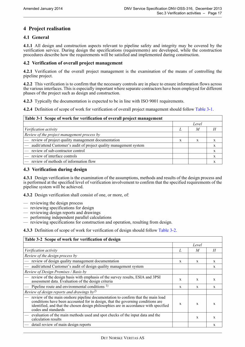
4.2.4 Definition of scope of work for verification of overall project management should follow Table 3-1.
4.3 Verification during design
4.3.1 Design verification is the examination of the assumptions, methods and results of the design process andis performed at the specified level of verification involvement to confirm that the specified requirements of thepipeline system will be achieved.
4.3.2 Design verification shall consist of one, or more, of:
— reviewing the design process— reviewing specifications for design— reviewing design reports and drawings— performing independent parallel calculations— reviewing specifications for construction and operation, resulting from design.
4.3.3 Definition of scope of work for verification of design should follow Table 3-2.
Table 3-1 Scope of work for verification of overall project management
Level
Verification activity L M H
Review of the project management process by
— review of project quality management documentation x x x
— audit/attend Customer’s audit of project quality management system x
— review of sub-contractor control x
— review of interface controls x
— review of methods of information flow x
Table 3-2 Scope of work for verification of design
Level
Verification activity L M H
Review of the design process by
— review of design quality management documentation x x x
— audit/attend Customer’s audit of design quality management system x
Review of Design Premises / Basis by
— review of the design basis with emphasis of the survey results, ESIA and 3PSI assessment data. Evaluation of the design criteria
x x x
— Pipeline route and environmental conditions 1) x x x
Review of design reports and drawings by2)
— review of the main onshore pipeline documentation to confirm that the main load conditions have been accounted for in design, that the governing conditions are identified, and that the chosen design philosophies are in accordance with specified codes and standards
x x x
— evaluation of the main methods used and spot checks of the input data and the calculation results
x x
— detail review of main design reports x

DET NORSKE VERITAS AS
Amended January 2014 DNV Service Specification DNV-DSS-316, December 2013
Sec.3 Verification activities – Page 18
Guidance note:
Design verification activities may be split between Basic Design (sometimes called FEED, and which may performedas a part of the Project Initiation phase) and Detailed Design, or other sub-phase, depending on type of contract.
---e-n-d---of---G-u-i-d-a-n-c-e---n-o-t-e---
4.4 Verification during construction
4.4.1 Verification during construction shall be carried out by means of full time attendance, audits, inspectionor spot checks of the work, as appropriate, in sufficient detail to confirm that the specified requirements of theonshore pipeline system will be achieved.
4.4.2 During construction verification shall consist of one, or more, of:
— reviewing the construction process— reviewing construction procedures— reviewing qualification process— surveillance during construction activities— reviewing final documentation.
4.4.3 Definition of scope of work for verification of construction should follow Table 3-3 and Table 3-4 formanufacturing and fabrication, Table 3-5 for installation and Table 3-6 for final testing and completion.
Performing independent parallel calculations by
— check of pressure containment x x x
— simplified independent analysis/calculation(s) performed by spot checks x x
— advanced independent analysis/calculation(s) performed by spot checks x
Review of specifications for construction and operation by
— spot check of critical aspects x x x
— hot tapping, vents and flares x x x
— review of main specifications x x
— thorough review of main specifications x
Review of flow assurance (non-integrity aspects3))
— general principles x x x
— review of main documents supported by simplified analyses x x
1) Verification activity to be agreed between Customer and DNV case by case considering aspects as:
– general knowledge of the area
– criticality of the results.
2) If the pipeline system is designed for different pressures along the pipeline (segmented design) this should be reflected in the verification scope of work regarding flow assurance, in addition to wall thickness, safety systems, etc.
3) These are optional verification services.
Table 3-3 Scope of work for verification of manufacturing and fabrication of linepipe and other pressure containing components
Level
Verification activity L M H
Review of the manufacturing & fabrication process
— Review of manufacturing and fabrication management systems x x x
— Audit/attend Customer’s audit of the quality management system x
Review of manufacturing & fabrication procedures
— Review manufacturing, fabrication and inspection procedures for confirmation of compliance with the manufacturing specification
x x x
— Review method statements x x
Review of qualification process
— Review the Manufacturing Procedure Specification, (MPS), Manufacturing Procedure Qualification Test (MPQT), if applicable
x x x
— Full time attendance during MPQT, if applicable, or first day production x x
Table 3-2 Scope of work for verification of design (Continued)
Level
Verification activity L M H

DET NORSKE VERITAS AS
Amended January 2014 DNV Service Specification DNV-DSS-316, December 2013
Sec.3 Verification activities – Page 19
Guidance note:
Linepipe and other materials may be ordered with certificates (e.g. 3.2 according to EN 10204). This can be integratedin the overall verification activities, so as not to duplicate work.
---e-n-d---of---G-u-i-d-a-n-c-e---n-o-t-e---
Surveillance during manufacturing and fabrication activities
— Visit-based attendance during testing, to confirm, based on spot checks, that the delivered products have been produced in accordance with the manufacturing specification
x x x
— Visit-based or full-time attendance during manufacturing and fabrication to confirm, based on spot checks, that the delivered products have been produced in accordance with the manufacturing specification
x x
— Full-time attendance during manufacturing and fabrication to confirm, based on spot checks, that the delivered products have been produced in accordance with the manufacturing specification
x
— for linepipe production only: overall independent verification of production by DNV x
Review of final documentation x x x
Table 3-4 Scope of work for verification of manufacturing and fabrication of coatings and other non-pressure containing components
Level
Verification activity L M H
Review of the manufacturing & fabrication process
— Review of manufacturing and fabrication management systems x x x
— Audit/attend Customer’s audit of the quality management system x
Review of manufacturing & fabrication procedures
— Review manufacturing, fabrication and inspection procedures for confirmation of compliance with the manufacturing specification
x x
Review of qualification process
— Review the Manufacturing Procedure Specification, (MPS), Manufacturing Procedure Qualification Test (MPQT), if applicable
x x x
— Full time attendance during MPQT, if applicable, or first day production x
Surveillance during manufacturing and fabrication activities
— Visit-based attendance during testing, to confirm, based on spot checks, that the delivered products have been produced in accordance with the manufacturing specification
x x
— Visit-based attendance during manufacturing and fabrication to confirm, based on spot checks, that the delivered products have been produced in accordance with the manufacturing specification
x
Review of final documentation x x x
Table 3-5 Scope of work for verification of installation
Level
Verification activity L M H
Review of the installation process
— Review of installation management systems x x x
— Audit/attend Customer’s audit of the quality management system x
Review of installation procedures
— Spot check of Installation Manual, (IM) x x x
— Critical evaluation of the Risk Register for the pipeline (the Risk Register should contain all the threads to the onshore pipeline system)
x x
Review of qualification process
— For critical operations, review the qualification of the IM x x x
— Full time attendance during qualification tests, if applicable, or production start-up x x
Table 3-3 Scope of work for verification of manufacturing and fabrication of linepipe and other pressure containing components (Continued)
Level
Verification activity L M H

DET NORSKE VERITAS AS
Amended January 2014 DNV Service Specification DNV-DSS-316, December 2013
Sec.3 Verification activities – Page 20
Surveillance during installation activities
— Visit-based attendance during start-up of construction activities (i.e. pipelaying, water crossings, CP installation, Block valve (BV) intervention works, Horizontal Directional Drilling (HDD) etc.)
x x x
— Full time attendance during qualification tests: visit- based attendance during construction
x x
— Full time attendance during construction (i.e. pipelaying, water crossings, HDD, CP and BV installation, intervention works
x
Review of final documentation x x x
Table 3-6 Scope of work for verification of final testing for operation, including as-built survey and project completion
Level
Verification activity L M H
Review of the process
— Review of management systems x x x
— Audit/attend Customer’s audit of the quality management system x
Review of procedures
— Review of procedures to confirm that the test procedures will test the onshore pipeline system in accordance with the design requirements: System pressure test, CP system and BV commissioning
x x x
Surveillance during testing and completion activities
— Full time attendance during pressure testing (min 24hrs). Visit based attendance during CP and BV commissioning
x x x
— Full time attendance during all pre-commissioning testings and audit based attendance during cleaning, gauging, de-watering and drying. Visit-based attendance during as-built surveying
x
Review of final documentation
— Spot check of as-built documentation x x x
— Review of as-built documentation x
Table 3-5 Scope of work for verification of installation (Continued)
Level
Verification activity L M H

DET NORSKE VERITAS AS
Amended January 2014 DNV Service Specification DNV-DSS-316, December 2013
Sec.4 Verification Service requirements – Page 21
SECTION 4 VERIFICATION SERVICE REQUIREMENTS
1 General
1.1 Objectives
1.1.1 The objectives of this section are to provide:
— details of DNV’s verification services for onshore pipeline systems — details of DNV’s deliverables for verification service for onshore pipeline systems.
1.2 Scope of work
1.2.1 The verification service is described in Sec.1 [1.3].
1.2.2 The scope of work is determined by and shall be described in a contract between DNV and the customer.
1.2.3 Sec.2 [4] describes the process of defining a risk-differentiated verification plan / scope of work. Thecustomer may stipulate the level of verification involvement.
2 Verification service documents
2.1 General
2.1.1 The type of DNV documents that may be issued depends on the extent and nature of the verificationscope of work.
2.1.2 DNV may issue verification service deliverables during the execution of the verification scope, and at itscompletion. The purpose of the deliverables is to document the scope of work performed, and the conclusionsreached, by DNV. The verification documents are as follows and the hierarchy is shown in Figure 4-1 below:
— Statement of Conformity— Verification Report— Intermediate documents:
— Audit reports— Verification Comments— Visit reports.
Figure 4-1 Document Hierarchy for Verification
2.1.3 Verification documents are, in principle, documents confirming that an examination has been carried out,and are valid only at the date of issue.
2.2 DNV Statement of conformity
2.2.1 A Statement of Conformity may be issued by DNV as a statement confirming that verification ofdocuments and/or activities has concluded that the pipeline system complies with specified requirements. Inorder for DNV to issue a Statement of Conformity the following requirements apply:
— the scope shall cover the complete pipeline system or a major self-contained part of it. Major self-contained
Verification Report
Intermediate documents
Statement of Conformity with accompanying
verification report

DET NORSKE VERITAS AS
Amended January 2014 DNV Service Specification DNV-DSS-316, December 2013
Sec.4 Verification Service requirements – Page 22
part shall mean a complete system, or the integration of more systems, to which risk based verification isor may be applied
— DNV shall have accepted the level of verification involvement to be satisfactory in relation to the risksassociated with the pipeline system or self-contained part of it
— it may be issued upon completion of the total verification scope, or at completion of logical phases, e.g.design or construction
— there shall not be omissions in the verification scope which may lead to misinterpretation of the Statementof Con-formity, e.g. in the design verification scope aspects like safety or structural integrity may not beomitted from individual components or systems
— there shall be no unresolved deviations, i.e. no open verification comments, which inherently infringe theintegrity of the pipeline system
— the statement is valid on the date of issue.
2.2.2 Alternatives to detailed requirements/solutions in the verification reference may be acceptable when theoverall integrity, safety and reliability level is documented and, in DNV’s interpretation, found to be equivalentor better than that of the verification reference. This principle of equivalence does not apply to verificationagainst non-DNV reference documents.
2.2.3 The Statement of Conformity shall be supported by a Verification Report, which shall be referenced fromthe Statement of Conformity.
2.3 Verification report
2.3.1 A Verification Report may be issued by DNV as a statement confirming the conclusion of theverification process. A Verification Report may in principle be issued at any stage of the verification process.
2.3.2 A Verification Report may be issued in conjunction with a Statement of Conformity.
2.3.3 A Verification Report may be in the form of a close-out report covering the completion of a self-contained part of the verification of a pipeline system.
2.3.4 A Verification Report may be the final deliverable if the requirements to a Statement of Conformity arenot fulfilled or a Statement of Conformity is not required.
2.3.5 Deviations from requirements shall be highlighted in the Verification Report. In the summary and/or inthe introduction, it shall be stated if there are unresolved deviations, with a reference to where in the report theyare addressed in detail. Deviations that are addressed through alternative solutions shall be included in the list.Such solutions may imply e.g. operational limitations.
2.3.6 In summary, thus, the Verification Report shall include:
— reference to the contract under which the work has been carried out— product or service description and item number, if relevant— application (operational limitations and conditions of use) for which the product is intended— verification scope of work, including level of verification involvement, if applicable— codes and Standards which the product or service has been verified against— clear statement of the conclusion from the verification (does it or does it not meet the specified
requirements)— list of documentation on which the verification report is based (reports, drawings, correspondence etc.)— unresolved deviations/non-conformities (open comments).
2.4 Intermediate documents
2.4.1 DNV may issue intermediate documentation of progress or conclusion related to individual verificationelements:
— a document review— a site visit— a test.
2.4.2 Intermediate deliverables may be in the form of:
— verification comments (May be listed in VerCom, Letter, email or other agreed communication type)— visit report— audit report— survey report.
2.5 Verification comments
2.5.1 Reviews of documents will be reported using Verification Comment Sheets (often called VerComs).

DET NORSKE VERITAS AS
Amended January 2014 DNV Service Specification DNV-DSS-316, December 2013
Sec.4 Verification Service requirements – Page 23
These documents give details to the Customer of aspects of onshore pipeline design and construction that DNV:
— considers not to meet the specified requirements— does not have enough information to make a conclusion— offers advice based on its experience.
Only in the first two instances DNV expects a response from the Customer or its contractors.
2.5.2 An example of a typical Verification Comment sheet is shown in App.B.
2.6 Audit report
2.6.1 Audit reports are issued to confirm that a company’s quality management system has been reviewed toconfirm compliance (or not) with the nominated standard and project requirements. In addition, the auditreports confirm compliance with the documented procedures and that these procedures are effective.
2.6.2 Audit reports will contain information such as whether:
— the company has a documented quality system— this quality system been certified by an accredited certification body for the product (or service) in question— the quality system adequately covers the following quality assurance elements for the product:
— organisation— authority/responsibility— job descriptions for key persons— internal quality audits— documentation change control— job instructions/procedures— nonconformity/corrective action.
— there are adequate procedures for activities such as:
— calibration of equipment— material identification and marking— control of special processes such as welding, NDT, PWHT— nonconformity identification and handling— inspection status— final inspection.
— the company’s facilities are, in general, considered adequate for the scope of supply— a quality plan has been prepared for the order concerned— the purchaser or their appointed inspection agency plan to attend the works— there are any problem areas identified.
2.6.3 An example of a typical Audit Report is shown in App.B.
2.7 Visit reports
2.7.1 Visit reports are documentation/recording of attendance activity by DNV.
Guidance note:
Visit reports may be referred as, e.g., Survey Report, Inspection Certificate, Site Report etc.
---e-n-d---of---G-u-i-d-a-n-c-e---n-o-t-e---
2.7.2 A visit report shall contain enough information to identify clearly the product or service that has beenexamined, the operating conditions or specifications to which it has been examined and the conclusion reachedby DNV.
2.7.3 The visit report will be issued on the relevant form and will contain as much information as possible inaccordance with the standard headings in the form. In addition, the report number shall be shown.
2.7.4 An example of a typical Visit Report is shown in App.B.
3 Use of quality management systems
3.1 General
3.1.1 The assurance of onshore pipeline integrity requires that gross errors during design, construction andoperation be minimised. The likelihood of gross errors shall be reduced in a systematic manner by the operationof a quality management system adequate for the work being carried out.
DET NORSKE VERITAS AS
Amended January 2014 DNV Service Specification DNV-DSS-316, December 2013
Sec.4 Verification Service requirements – Page 24
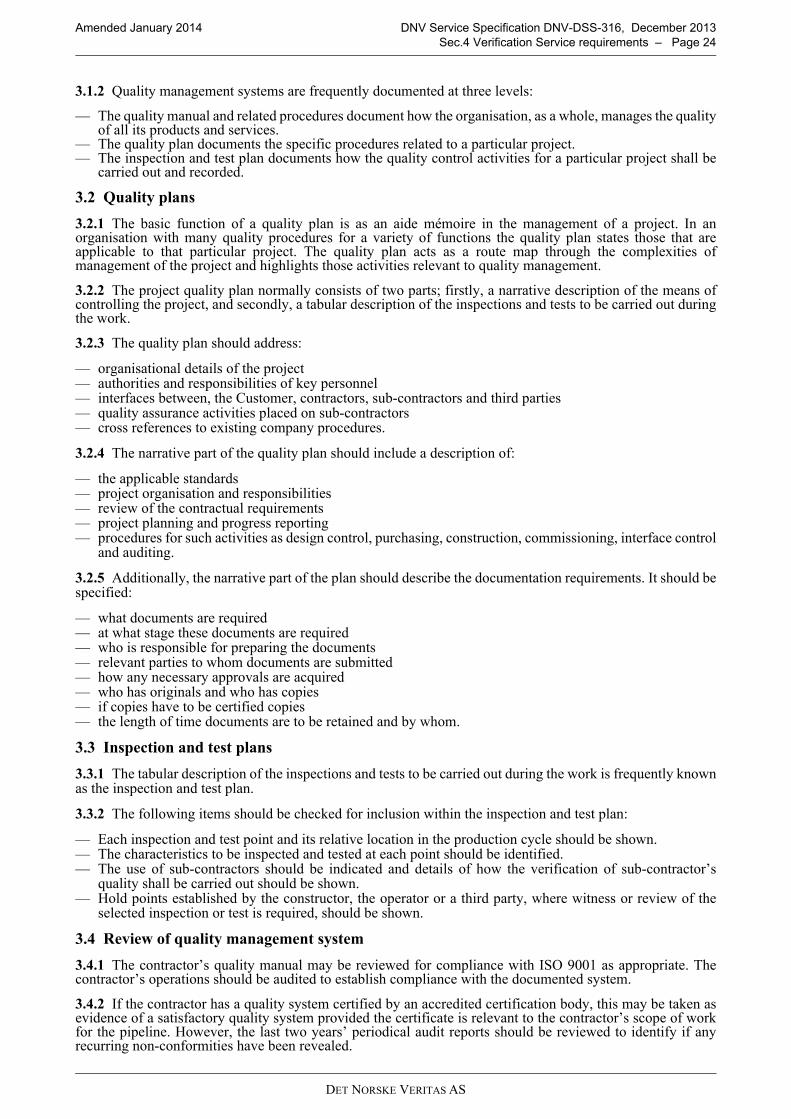
3.1.2 Quality management systems are frequently documented at three levels:
— The quality manual and related procedures document how the organisation, as a whole, manages the qualityof all its products and services.
— The quality plan documents the specific procedures related to a particular project.— The inspection and test plan documents how the quality control activities for a particular project shall be
carried out and recorded.
3.2 Quality plans
3.2.1 The basic function of a quality plan is as an aide mémoire in the management of a project. In anorganisation with many quality procedures for a variety of functions the quality plan states those that areapplicable to that particular project. The quality plan acts as a route map through the complexities ofmanagement of the project and highlights those activities relevant to quality management.
3.2.2 The project quality plan normally consists of two parts; firstly, a narrative description of the means ofcontrolling the project, and secondly, a tabular description of the inspections and tests to be carried out duringthe work.
3.2.3 The quality plan should address:
— organisational details of the project— authorities and responsibilities of key personnel— interfaces between, the Customer, contractors, sub-contractors and third parties— quality assurance activities placed on sub-contractors— cross references to existing company procedures.
3.2.4 The narrative part of the quality plan should include a description of:
— the applicable standards— project organisation and responsibilities— review of the contractual requirements— project planning and progress reporting— procedures for such activities as design control, purchasing, construction, commissioning, interface control
and auditing.
3.2.5 Additionally, the narrative part of the plan should describe the documentation requirements. It should bespecified:
— what documents are required— at what stage these documents are required— who is responsible for preparing the documents— relevant parties to whom documents are submitted— how any necessary approvals are acquired— who has originals and who has copies— if copies have to be certified copies— the length of time documents are to be retained and by whom.
3.3 Inspection and test plans
3.3.1 The tabular description of the inspections and tests to be carried out during the work is frequently knownas the inspection and test plan.
3.3.2 The following items should be checked for inclusion within the inspection and test plan:
— Each inspection and test point and its relative location in the production cycle should be shown.— The characteristics to be inspected and tested at each point should be identified.— The use of sub-contractors should be indicated and details of how the verification of sub-contractor’s
quality shall be carried out should be shown.— Hold points established by the constructor, the operator or a third party, where witness or review of the
selected inspection or test is required, should be shown.
3.4 Review of quality management system
3.4.1 The contractor’s quality manual may be reviewed for compliance with ISO 9001 as appropriate. Thecontractor’s operations should be audited to establish compliance with the documented system.
3.4.2 If the contractor has a quality system certified by an accredited certification body, this may be taken asevidence of a satisfactory quality system provided the certificate is relevant to the contractor’s scope of workfor the pipeline. However, the last two years’ periodical audit reports should be reviewed to identify if anyrecurring non-conformities have been revealed.

DET NORSKE VERITAS AS
Amended January 2014 DNV Service Specification DNV-DSS-316, December 2013
Sec.4 Verification Service requirements – Page 25
3.4.3 Any weaknesses revealed during this audit, or review of periodical audit reports, should be consideredwhen planning the contractor monitoring activities.
3.4.4 Surveillance of the continuing acceptability of the contractor’s quality management system is carried outby observing a selection of audits carried out by the contractor as part of its internal audit system. The auditsto be observed should be selected over the length of the project at suitable intervals and should cover as widea selection of activities as possible.
3.4.5 Contractors’ inspection and test plans for the various activities undertaken during their scope of work forthe pipeline should be reviewed and accepted, if adequate.

DET NORSKE VERITAS AS
Amended January 2014 DNV Service Specification DNV-DSS-316, December 2013
App.A Guideline on selection of verification involvement level based on simplified verification planning – Page 26
APPENDIX A GUIDELINE ON SELECTION OF VERIFICATION INVOLVEMENT LEVEL BASED ON SIMPLIFIED VERIFICATION
PLANNING
A.1 General
A.1.1 General principles
A.1.1.1 The selection of the level of verification involvement depends on the criticality of each of the elementsthat have an impact on the management of risks associated with the pipeline system.
A.1.1.2 The verification process shall direct greatest effort at those elements of the pipeline system where therisk is highest and whose failure or reduced performance will have the most significant impact regarding:
— pipeline integrity— safety risks— environmental risks— economic risks— regulatory risks.
A.1.1.3 Suitable selection factors include, but are not limited to, the:
— overall safety objectives for the pipeline system— assessment of the risks associated with the pipeline and the measures taken to reduce these risks— degree of technical innovation in the pipeline system— experience of the contractors in carrying out the work— quality management systems of the Customer and its contractors.
A.1.1.4 Due to the diversity of various pipeline systems, their contents, their degree of innovation, thegeographic location, et cetera, it is not possible to give precise directions on how to decide what level ofverification involvement is appropriate for each particular pipeline system.
A.1.1.5 Therefore, guidance is given as a series of questions that should be answered when deciding theappropriate level of verification involvement for a pipeline system. This list is not exhaustive and otherquestions should be added to the list if appropriate for a particular pipeline system.
A.1.1.6 It must be emphasised that the contribution of each element should be judged qualitatively and/orquantitatively. Wherever possible quantified risk assessment data should be used to provide a justifiable basisfor any decisions made.
A.1.1.7 Depending on the stage of the project, the activities may not have taken place yet in which case thequestions can also be posed in another form, i.e. “Is …. planned to be implemented?”
A.2 Trigger questions
A.2.1 Overall safety objective
— Does the safety objective address the main safety goals?— Does the safety objective establish acceptance criteria for the level of risk acceptable to the Customer?— Is this risk (depending on the pipeline and its location) measured in terms of human injuries as well as
environmental, economic, regulatory and political consequences?
A.2.2 Assessment of risk
— Has a systematic review been carried out to identify and evaluate the probabilities and consequences offailures in the pipeline system?
— Has this review judged the contribution of each element qualitatively and/or quantitatively and used, wherepossible, quantified risk assessment data to provide a justifiable basis for any decisions made?
— Does the extent of the review reflect the criticality of the pipeline system, the planned operation andprevious experience with similar pipeline systems?
— Does this review identify the risk associated with the operation of the pipeline system and to the health andsafety of personnel associated with it or in its vicinity?
— Has the extent of the identified risks been reduced to a level as low as reasonably practicable by means ofone or both of:
— Reduction in the probability of failure?— Mitigation of the consequences of failure?
DET NORSKE VERITAS AS
Amended January 2014 DNV Service Specification DNV-DSS-316, December 2013
App.A Guideline on selection of verification involvement level based on simplified verification planning – Page 27
— Has the result of the systematic review of the risks been measured against the Customer’s safety objective?— Has the result of this review been used in the selection of the appropriate verification activity level?
A.2.3 Technical innovation
— Has the degree of technical innovation in the pipeline system been considered?— Has it been considered that risks associated with the pipeline are likely to be greater with a high degree of
technical innovation than with a pipeline designed, manufactured and installed to well-accepted criteria inwell-understood environmental conditions?
— Have factors been considered in the selection of the appropriate verification level involvement such as:
— Degree of difficulty in achieving technical requirements.— Knowledge of similar pipelines.— Effect of the new pipeline on the surrounding area.
A.2.4 Contractors’ experience
— Has the degree of risk associated with the pipeline system been considered where design, manufacturer andfabrication, construction or installation contractors are inexperienced?
— Has the degree of risk been considered where the contractors are experienced but not in similar work?— Has the degree of risk been considered where the work schedule is tight?
A.2.5 Quality management systems
— Have all parties involved in the pipeline system implemented an adequate quality management system toensure that gross errors in the work are limited?
— Do these parties include the:
— Owner— Design contractor— Line pipe and component manufacturers— Fabricators— Construction contractors— Installation contractor— Operator— Do the factors being considered when evaluating the adequacy of the quality management system
include:
— Whether or not an ISO 9001 or equivalent certified system is in place— Results from external audits— Results from internal audits— Experience with contractors’ previous work— Project work force familiarity with the quality management system.

DET NORSKE VERITAS AS
Amended January 2014 DNV Service Specification DNV-DSS-316, December 2013
App.B Examples of verification documents – Page 28
APPENDIX B EXAMPLES OF VERIFICATION DOCUMENTS
B.1 General
B.1.1 Introduction
B.1.1.1 This appendix includes example forms for use by DNV in the verification of pipeline systems.
The following forms are included:
— Statement of Conformity— Verification Comments Sheet— Audit Report— Visit Report

DET NORSKE VERITAS AS
Amended January 2014 DNV Service Specification DNV-DSS-316, December 2013
App.B Examples of verification documents – Page 29
B.1.2 Statement of conformity
DET NORSKE VERITAS AS, Veritasveien 1, NO-1322 Høvik, Norway, Tel.: +47 67 57 99 00, Org.No. NO 945 748 931 MVA. www.dnv.com
Form No.: VER 01a Issue: 2013-10 Page 1 of 1
Statement No:
DET NORSKE VERITAS
STATEMENT OF CONFORMITY
Owner:
Name of system/installation:
Location:
Description:
Main Operational Limitations: Pressure: Temperature: Service:
THIS IS TO VERIFY: That the above mentioned system/installation has been verified, by appropriate methods, to comply with the requirements of , for the main operational limits stated above, and further outlined in the Reference documents listed below.
Verification Involvement: The verification of the above mentioned system/installation has been performed in accordance with DNV Service Specification for Verification of , DNV-DSS-3 with the detailed scope of work described in the Reference documents mentioned below. Validity: This statement is valid on the date of issue. Reference documents: (appended) Issued at (place) on (yyyy-mm-dd)
for Det Norske Veritas AS
(name)
Project Sponsor
ILLUSTRATION ONLY
nstallation has been verified, by appropriate nstallation has been verified, by appropriate methods, to comply with the requirements of methods, to comply with the requirements of limits stated above, and furtherlimits stated above, and further outlined in the Reference documents listed below. outlined in the Reference documents listed below. limits stated above, and further
The verification of the above mentioned system/installation has been performed in accordance with DNV Service Specification The verification of the above mentioned system/installation has been performed in accordance with DNV Service Specification for Verification of , DNV-DSS-3 with the detailed scofor Verification of , DNV-DSS-3 with the detailed sco
Validity: Validity: This statement is valid This statement is valid
This picture is provided solely for illustration. It
may deviate somewhat from the current version of th
e illustrated form
methods, to comply with the requirements of methods, to comply with the requirements of outlined in the Reference documents listed below. outlined in the Reference documents listed below.
The verification of the above mentioned system/installation has been performed in accordance with DNV Service Specification The verification of the above mentioned system/installation has been performed in accordance with DNV Service Specification for Verification of , DNV-DSS-3 with the detailed scofor Verification of , DNV-DSS-3 with the detailed scope of work described in the Reference documents mentioned below. pe of work described in the Reference documents mentioned below.
on the date of issue. on the date of issue.
Reference documents: Reference documents: (appended) (appended)

DET NORSKE VERITAS AS
Amended January 2014 DNV Service Specification DNV-DSS-316, December 2013
App.B Examples of verification documents – Page 30
B.1.3 Verification comments sheet
���������������������������
������������� ��� �����������
��������������� ����������� ����� �� �� �������������
���!������� ����� �� �� ��"�#�����
$�"���������"���#�������������%�#���������������#���#!�������#��"�������������������&'�(���)����)��)�
����������������������
������������
����! ��� �� �"��#�� � � $��%
*
+
,
-
.
/
0
1
2
*3
����#�
�� �"��#��
���&���������� #�%����!�����������������������%������������#���������������#��������� �&��%��%���������������4��������#�����������#������ �����#��!���������
�'�&��������(�'$��#�%����"��&��!��%�#�������������������������������������%����!�����������4��#�����#�#���������
��&��)*���+��!(#��� ����)�),�%����!�����������������������%������������#�����������#��������� �&��%��%���������������4��������#���������!!��#�����������"������#��������#��5��������
� � $��%
��6�����7�6�7��#���8��4����#�����!������9
ILLUSTRATION ONLY
1
22ILLUSTRATION ONLY
ILLUSTRATION ONLY
ILLUSTRATION ONLY
ILLUSTRATION ONLY
ILLUSTRATION ONLY
ILLUSTRATION ONLY
ILLUSTRATION ONLY
ILLUSTRATION ONLY
ILLUSTRATION ONLY
ILLUSTRATION ONLY
This picture is provided solely for illustration. It
may deviate somewhat from the current version of th
e illustrated form
This picture is provided solely for illustration. It
may deviate somewhat from the current version of th
e illustrated form
This picture is provided solely for illustration. It
may deviate somewhat from the current version of th
e illustrated form
This picture is provided solely for illustration. It
may deviate somewhat from the current version of th
e illustrated form
*3*3This picture is provided solely for illustration. It
may deviate somewhat from the current version of th
e illustrated form
This picture is provided solely for illustration. It
may deviate somewhat from the current version of th
e illustrated form
This picture is provided solely for illustration. It
may deviate somewhat from the current version of th
e illustrated form
This picture is provided solely for illustration. It
may deviate somewhat from the current version of th
e illustrated form
This picture is provided solely for illustration. It
may deviate somewhat from the current version of th
e illustrated form
This picture is provided solely for illustration. It
may deviate somewhat from the current version of th
e illustrated form
This picture is provided solely for illustration. It
may deviate somewhat from the current version of th
e illustrated form
This picture is provided solely for illustration. It
may deviate somewhat from the current version of th
e illustrated form
This picture is provided solely for illustration. It
may deviate somewhat from the current version of th
e illustrated form
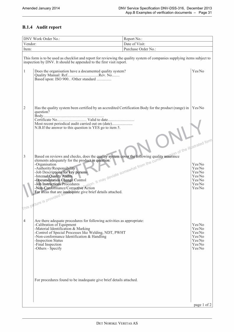
DET NORSKE VERITAS AS
Amended January 2014 DNV Service Specification DNV-DSS-316, December 2013
App.B Examples of verification documents – Page 31
B.1.4 Audit report
���:��;����������� �����������
������ ������!��#���
����� ���%�#������������
�%�#�!�����#��������#����#��%��;��#�������������!�����"��&�� ��%��4�������#�#�����!���������#�#������� �����#�#������������#������������������#%���������������������%��!��#��"�#����������
* ���#��%���� ���#������%�"���������������4�������#�#���'<�������=���������!����������������������������������"������������>�#�������������233���)��%���#�����������������������
(�#)��
+ $�#��%��4�������#�#��������������!���������������������7����!��������>����!����%����������8��� �9����4��#����'>�����������������������������������������������������������������7����!�������������������������������������������������������������������������������=�#�����������������������������������������8����9�����������������������>��!��%����#&�������%�#�4��#������#�(��� ����������.�
(�#)��
, >�#��������"��&#������%��;#?����#��%��4�������#�#������"����%��!����&�� �4��������##��������������#����4�������!����%�������������4��#�����@�� ���#�����@���%�����)��#���#�������@A�����#��������#�!���;������#��#@���������<������������#@��������������7%�� ��7������@A�����#��������#) ��������#@���@7��!�������)7�������"��������B�������#��%������������4����� �"������!�������#������%���
(�#)��(�#)��(�#)��(�#)��(�#)��(�#)��(�#)��
- �����%�������4��������������#�!���!����&�� �����"����#��#�������������@7������������!��4�������@=��������������!��������C�=��;�� @7��������!��������� ����##�#���;��:����� ?����?� :$�@���@���!��������������!��������C�$������ @��#�������������#@B�������#�������@��%��#�@������!�
B������������#�!����������������4����� �"������!�������#������%���
(�#)��(�#)��(�#)��(�#)��(�#)��(�#)��(�#)��
�� ��*��!�+
ILLUSTRATION ONLY
, >�#��������"��&#������%��;#?����#��%��4�������#�#������"����%��!����&�� �4��������##�������, >�#��������"��&#������%��;#?����#��%��4�������#�#������"����%��!����&�� �4��������##��������������#����4�������!����%�������������4��#������������#����4�������!����%�������������4��#�����
@���%�����)��#���#�������@���%�����)��#���#�������@A�����#��������#�!���;������#��#@A�����#��������#�!���;������#��#@���������<������������#@���������<������������#@��������������7%�� ��7������@��������������7%�� ��7������@A�����#��������#) ��������#@A�����#��������#) ��������#@���@7��!�������)7�������"��������@���@7��!�������)7�������"��������ILLUSTRATION ONLY
B�������#��%������������4����� �"������!�������#������%���B�������#��%������������4����� �"������!�������#������%���ILLUSTRATION ONLY
ILLUSTRATION ONLY
This picture is provided solely for illustration. It
may deviate somewhat from the current version of th
e illustrated form
, >�#��������"��&#������%��;#?����#��%��4�������#�#������"����%��!����&�� �4��������##�������, >�#��������"��&#������%��;#?����#��%��4�������#�#������"����%��!����&�� �4��������##�������
@���@7��!�������)7�������"��������@���@7��!�������)7�������"��������
This picture is provided solely for illustration. It
may deviate somewhat from the current version of th
e illustrated form
B�������#��%������������4����� �"������!�������#������%���B�������#��%������������4����� �"������!�������#������%���
This picture is provided solely for illustration. It
may deviate somewhat from the current version of th
e illustrated form
This picture is provided solely for illustration. It
may deviate somewhat from the current version of th
e illustrated form
This picture is provided solely for illustration. It
may deviate somewhat from the current version of th
e illustrated form
This picture is provided solely for illustration. It
may deviate somewhat from the current version of th
e illustrated form

DET NORSKE VERITAS AS
Amended January 2014 DNV Service Specification DNV-DSS-316, December 2013
App.B Examples of verification documents – Page 32
. ������ ���#�����D#�!��������#���� ����������#����������4�����!����%��#������!�#�����' (�#)��
/ $�#�<������� ������������������!����%�����������������'��!�������������������������������������"���������
(�#)��
0 ����������������������������������%����������������#��������� ������������������':%��%���#��������� ����'���������������������������������������������������
(�#)��
1 ��������������������#�������!����@�E�"��������#
��=�� ��������
��E�� �����
���������#%���#������%����(�#)��
�� ��+��!�+
ILLUSTRATION ONLY
1 ��������������������#�������!����@�E�"��������#1 ��������������������#�������!����@�E�"��������#
This picture is provided solely for illustration. It
may deviate somewhat from the current version of th
e illustrated form
This picture is provided solely for illustration. It
may deviate somewhat from the current version of th
e illustrated form
This picture is provided solely for illustration. It
may deviate somewhat from the current version of th
e illustrated form

DET NORSKE VERITAS AS
Amended January 2014 DNV Service Specification DNV-DSS-316, December 2013
App.B Examples of verification documents – Page 33
B.1.5 Visit report
���:��;����������� �����������
������ ������!��#���
����� ���%�#������������
��"�#�����������#�����������������!�����"����#��"���������"�#�������#%�������!�5�������������������������������������������������&��%���,����#��!��%��"�#�����!���4�����?�����#�� �"��!���%���������#����#��������#%����
* ����4�������#�#�������������#���%�������'�!���?�����#�� �"��������#�
(�#)��
+ ����!����������)��#����������4��������#���!��������"�����F#�4���������������� ����@>���%��"�����'(�#)��@>������������������������������%����������������#��������� ����'(�#)��@��%���������#?��!�����8#����!������������������������������������9(�#)���!���?�����#�� �"��������#�
, �#������������������� �������������������������#���4�����'�!���?�����#�� �"��������#�
- �����%�����������#������ ����@���!�������#)��������"�����������4�����'�!���#?�����#�� �"��������#�
. E�"������!�������#��!������������#����#����������#���!�"�#���������<@ ������!��������������������������
/ E�"������!�������#��!�&��;�������������!�����5��"�#���������<@ ������!��������������������������
0 �������������#��!��������������!�����������4��#����!������%���������#����������"��������
��=�� ��������
��E�� �����
���������#%���#������%����(�#)��
ILLUSTRATION ONLY
- �����%�����������#������ ����@���!�������#)��������"�����������4�����'- �����%�����������#������ ����@���!�������#)��������"�����������4�����'�!���#?�����#�� �"��������#��!���#?�����#�� �"��������#�
. E�"������!�������#��!������������#����#����������#���!�"�#���. E�"������!�������#��!������������#����#����������#���!�"�#���
This picture is provided solely for illustration. It
may deviate somewhat from the current version of th
e illustrated form
- �����%�����������#������ ����@���!�������#)��������"�����������4�����'- �����%�����������#������ ����@���!�������#)��������"�����������4�����'
. E�"������!�������#��!������������#����#����������#���!�"�#���. E�"������!�������#��!������������#����#����������#���!�"�#���������<@ ������!��������������������������������<@ ������!��������������������������
This picture is provided solely for illustration. It
may deviate somewhat from the current version of th
e illustrated form
This picture is provided solely for illustration. It
may deviate somewhat from the current version of th
e illustrated form

DET NORSKE VERITAS AS
Amended January 2014 DNV Service Specification DNV-DSS-316, December 2013
App.C Detailed scope of work tables for verification – Page 34
APPENDIX C DETAILED SCOPE OF WORK TABLES FOR VERIFICATION
C.1 General
C.1.1 Introduction
C.1.1.1 This appendix gives the format of the detailed scope of work tables that should be made for eachparticular project.
C.1.1.2 The detailed project specific scope of work tables for the chosen level of verification involvementshould be based on these tables. For pipeline project scenarios of components not covered in this Appendixsimilar tables with the same degree of detail, should be made.
C.1.1.3 If any of the activities are moved from one phase to another, then this must be identified clearly on thetable where it is removed. Similarly, the detailed table for the phase to where it is moved should be amended.
Guidance note:
Typically, contractual boundaries may give natural splits of activities between phases. However, then it is even moreimportant to ensure that there is a traceability as to which phases what activity belong and that this is conveyed to thecontractors also.
---e-n-d---of---G-u-i-d-a-n-c-e---n-o-t-e---
C.2 Description of terms used in the scope of work tables
C.2.1 General
C.2.1.1 The following abbreviations and definitions have been used:
— X is part of scope; attendance at meeting, issue report, etc.
— A is Audit
— S is Surveillance
— I is For Information
— R is Review.
C.2.1.2 These abbreviations are DNV’s preferred terms and should be used in DNV-generated documents.However, other terms, for example monitoring or witnessing, may be used by DNV if these are the termscommonly used in documents, such as Inspection and Test Plans, generated by others. In that case, it isexpected that these other terms are defined in these documents.
C.2.2 Audit
C.2.2.1 Systematic, independent and documented process for obtaining audit evidence and evaluating itobjectively to determine the extent to which audit criteria are fulfilled. (ISO 9001: 2008).
Guidance note:
This activity differs from the Surveillance by being focused on the adherence to and completeness and robustness ofthe procedures and not on the actual result of the procedure (although this is not ignored). Further, the audit isnormally a ‘one-off’ activity as opposed to the continuity in monitoring.
---e-n-d---of---G-u-i-d-a-n-c-e---n-o-t-e---
C.2.3 Review
C.2.3.1 Systematic examination of reports and documentation. The depth of review will depend on the type ofdocument, any independent analyses/calculations performed by DNV, project phase and the level ofverification involvement. In principle, it is the solutions for the design, construction and operation elementsdescribed in the documents that shall be verified.
C.2.3.2 The documents shall be divided into verification documents and reference documents. Verificationdocuments are the documents DNV shall verify. Reference documents are the documents against which theverification documents are verified. DNV may rely on the information in the reference documents and shallhave no obligation to review, evaluate or verify this information. DNV may notify the customer of an error ina reference documents, however, this does not mean that DNV reviewed, evaluated or verified the referencedocument.
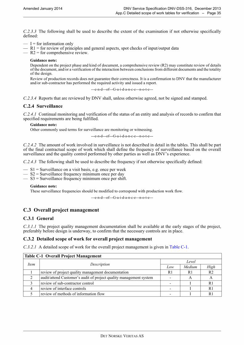
DET NORSKE VERITAS AS
Amended January 2014 DNV Service Specification DNV-DSS-316, December 2013
App.C Detailed scope of work tables for verification – Page 35
C.2.3.3 The following shall be used to describe the extent of the examination if not otherwise specificallydefined:
— I = for information only— R1 = for review of principles and general aspects, spot checks of input/output data— R2 = for comprehensive review.
Guidance note:
Dependent on the project phase and kind of document, a comprehensive review (R2) may constitute review of detailsof the document, and/or a verification of the interaction between conclusions from different documents and the totalityof the design.
Review of production records does not guarantee their correctness. It is a confirmation to DNV that the manufacturerand/or sub-contractor has performed the required activity and issued a report.
---e-n-d---of---G-u-i-d-a-n-c-e---n-o-t-e---
C.2.3.4 Reports that are reviewed by DNV shall, unless otherwise agreed, not be signed and stamped.
C.2.4 Surveillance
C.2.4.1 Continual monitoring and verification of the status of an entity and analysis of records to confirm thatspecified requirements are being fulfilled.
Guidance note:
Other commonly used terms for surveillance are monitoring or witnessing.
---e-n-d---of---G-u-i-d-a-n-c-e---n-o-t-e---
C.2.4.2 The amount of work involved in surveillance is not described in detail in the tables. This shall be partof the final contractual scope of work which shall define the frequency of surveillance based on the overallsurveillance and the quality control performed by other parties as well as DNV’s experience.
C.2.4.3 The following shall be used to describe the frequency if not otherwise specifically defined:
— S1 = Surveillance on a visit basis, e.g. once per week— S2 = Surveillance frequency minimum once per day— S3 = Surveillance frequency minimum once per shift.
Guidance note:
These surveillance frequencies should be modified to correspond with production work flow.
---e-n-d---of---G-u-i-d-a-n-c-e---n-o-t-e---
C.3 Overall project management
C.3.1 General
C.3.1.1 The project quality management documentation shall be available at the early stages of the project,preferably before design is underway, to confirm that the necessary controls are in place.
C.3.2 Detailed scope of work for overall project management
C.3.2.1 A detailed scope of work for the overall project management is given in Table C-1.
Table C-1 Overall Project Management
Item DescriptionLevel
Low Medium High
1 review of project quality management documentation R1 R1 R2
2 audit/attend Customer’s audit of project quality management system - A A
3 review of sub-contractor control - I R1
4 review of interface controls - I R1
5 review of methods of information flow - I R1
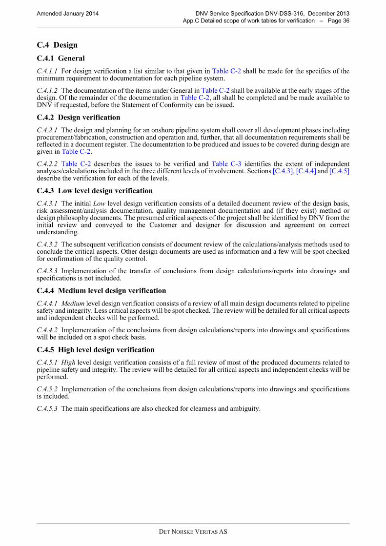
DET NORSKE VERITAS AS
Amended January 2014 DNV Service Specification DNV-DSS-316, December 2013
App.C Detailed scope of work tables for verification – Page 36
C.4 Design
C.4.1 General
C.4.1.1 For design verification a list similar to that given in Table C-2 shall be made for the specifics of theminimum requirement to documentation for each pipeline system.
C.4.1.2 The documentation of the items under General in Table C-2 shall be available at the early stages of thedesign. Of the remainder of the documentation in Table C-2, all shall be completed and be made available toDNV if requested, before the Statement of Conformity can be issued.
C.4.2 Design verification
C.4.2.1 The design and planning for an onshore pipeline system shall cover all development phases includingprocurement/fabrication, construction and operation and, further, that all documentation requirements shall bereflected in a document register. The documentation to be produced and issues to be covered during design aregiven in Table C-2.
C.4.2.2 Table C-2 describes the issues to be verified and Table C-3 identifies the extent of independentanalyses/calculations included in the three different levels of involvement. Sections [C.4.3], [C.4.4] and [C.4.5]describe the verification for each of the levels.
C.4.3 Low level design verification
C.4.3.1 The initial Low level design verification consists of a detailed document review of the design basis,risk assessment/analysis documentation, quality management documentation and (if they exist) method ordesign philosophy documents. The presumed critical aspects of the project shall be identified by DNV from theinitial review and conveyed to the Customer and designer for discussion and agreement on correctunderstanding.
C.4.3.2 The subsequent verification consists of document review of the calculations/analysis methods used toconclude the critical aspects. Other design documents are used as information and a few will be spot checkedfor confirmation of the quality control.
C.4.3.3 Implementation of the transfer of conclusions from design calculations/reports into drawings andspecifications is not included.
C.4.4 Medium level design verification
C.4.4.1 Medium level design verification consists of a review of all main design documents related to pipelinesafety and integrity. Less critical aspects will be spot checked. The review will be detailed for all critical aspectsand independent checks will be performed.
C.4.4.2 Implementation of the conclusions from design calculations/reports into drawings and specificationswill be included on a spot check basis.
C.4.5 High level design verification
C.4.5.1 High level design verification consists of a full review of most of the produced documents related topipeline safety and integrity. The review will be detailed for all critical aspects and independent checks will beperformed.
C.4.5.2 Implementation of the conclusions from design calculations/reports into drawings and specificationsis included.
C.4.5.3 The main specifications are also checked for clearness and ambiguity.

DET NORSKE VERITAS AS
Amended January 2014 DNV Service Specification DNV-DSS-316, December 2013
App.C Detailed scope of work tables for verification – Page 37
C.4.6 Scope of work for design
C.4.6.1 Detailed scope of work for design is given in Table C-2 and Table C-3.
Table C-2 Pipeline integrity design
Item DescriptionLevel
Low Medium High
General
1. Safety objective I I I
2.Confirmation that the different contractors and sub-contractors’ quality systems meet the requirements of ISO 9000
R1 R1 R1
3. Description of pipeline system and overall project organization I I R1
4. Survey Report I I R1
5. Risk assessment and identification of critical aspects R1 R1 R1
6. Document register I I I
Main
7. Design basis R1 R1 R2
8. Pipeline operation and control philosophy report R1 R1 R2
9. Process Flow Diagram (PFD) I R1 R1
10. Pressure protection system / SCADA R1 R1 R2
11.
Pipeline routing (taking into account geotechnical hazards and recommended routing, compliance with defined safety distances from risk assessments, land use reports, identified crossings, statutory permits)
I R1 R2
12. Physical and chemical characteristics of fluid I I R1
13.Materials selection including internal corrosion assessment (line pipe and pipeline components)
R1 R1 R2
14.Flow assurance (temperature/pressure profiles, slugging, thermo hydraulic analyses)
R1 R1 R2
14. Pressure containment (wall thickness calculations) R1 R1 R2
16. Engineering Critical Assessment – Fracture Control R1 R1 R2
17.Pipeline Mechanical design (concentrated loads, expansion, bending, anchor block and buoyancy where applicable)
R1 R1 R2
18. Road/railway/river crossings R1 R1 R2
19.Protection against accidental loads i.e third party, lightning, soil subsistence, slides, flooding and earthquake (whatever applicable)
R1 R1 R2
20. Pipe branch design I R1 R1
21. Pipe lifting analysis I R1 R1
22. Pump or Compressor stations specification1) R1 R1 R2
23. Pig trap I R1 R1
24. Valve/ Actuator specification I R1 R1
25. Valve/ Actuator calculation I R1 R1
26. Flange specification R1 R1 R1
27. Fitting specification R1 R1 R1
28. Induction bend specification R1 R1 R1
29.Pipeline installation specification (Route preparation, line pipe transportation, handling and stockpiling, pipe string lifting and lowering, excavation and backfilling)
R1 R1 R2
30. Emergency Plan R1 R1 R2
31. Isolation joint specification I R1 R2
32. Pre-commissioning and commissioning specification R1 R1 R2
Main drawings
33. Pipeline route drawings R1 R1 R1
34. Detailed pipeline crossing drawings I R1 R1

DET NORSKE VERITAS AS
Amended January 2014 DNV Service Specification DNV-DSS-316, December 2013
App.C Detailed scope of work tables for verification – Page 38
Note: that verification of pump or compressor stations is not a part of the scope for this DSS. In case suchstations are a part of the pipeline system they have to be considered and some guidance can be found in DNV-OSS-307 Process Facilities.
The activities presented in the Table C-3 above can be done based on agreement.
Line pipe and pipeline components (including welding)
35. Line pipe specifications R1 R1 R2
36. Welding specifications R1 R1 R2
37. Material take off/data sheets - I R1
Corrosion control systems
38. Corrosion protection design report R1 R1 R1
39. Corrosion protection specifications I R1 R1
40. Coating specifications I R1 R1
41. Field joint coating specification(s) I R1 R1
42. Corrosion monitoring system specification I R1 R1
43. Material take off/data sheets - I R1
Pipeline control and safety systems
44. Pipeline Control and Safety System Philosophy R1 R1 R2
45. Functional Safety Management Plan R1 R1 R2
46.SIL (Safety Integrity Level) Allocation Report for the Pipeline Safety System
I R1 R2
47. Safety Requirements Specification I R1 R2
48. SIL Verification Report I R1 R1
49. Pipeline Control System (PCS) Functional Design Specification I R1 R1
Table C-3 Independent analyses/calculations for pipeline integrity design (Optional)
Item Activity DescriptionLevel
Low Medium High
1. Wall thickness Calculations based on empirical formulas x x x
2. ExpansionCalculations based on empirical formulas; Ensure that spools are adequately designed to absorb the expansion.
(x) x x
3. Global bucklingCalculations based on empirical formulas;Check safety margins against vertical movement of pipeline.
(x) x
4. Spool Calculations based on empirical formulas (x)
5. SoilCalculations based on empirical formulas; Soil support/foundation, pipe-soil interaction incl. resistance towards axial and upheaval movement.
(x) x
6. Corrosion Corrosion analysis (x) (x)
7. BuoyancyBuoyancy calculations where there is high water table, muskeg, water crossings etc
(x) x x
8. Steady state flowPressure loss calculations based on analytical formulas
x
9. Crossing DesignCalculations based on empirical formulas or numerical analysis
(x) x x
x = analysis/check will be included in the scope of work (if relevant)(x) = analysis/check should be included in the scope of work if the issue is identified as critical or highly utilised. Then final decision of inclusion in the scope of work will be a result of the document review of simple analysis.
Table C-2 Pipeline integrity design (Continued)
Item DescriptionLevel
Low Medium High

DET NORSKE VERITAS AS
Amended January 2014 DNV Service Specification DNV-DSS-316, December 2013
App.C Detailed scope of work tables for verification – Page 39
C.5 Construction
C.5.1 General
C.5.1.1 Construction of onshore pipelines consists of a number of different site activities and their associateddocumentation.
C.5.1.2 Table C-4 and Table C-5 summarise the scope of work tables included in this section for variousconstruction activities.
C.5.1.3 For onshore pipeline construction, Quality Surveillance lists similar to those shown hereafter shall bemade for the specifics of the particular project.
C.5.2 Construction quality surveillance
C.5.2.1 For verification and Quality Surveillance of onshore pipeline systems construction activities areconsidered as:
— initial verification activities— inspection activities — final activities.
C.5.2.2 The initial verification activities include the review of procedures, attendance during qualification ofprocedures (e.g. MPQT) and personnel (e.g. welders etc.) and other start-up activities. The inspection activities are the manufacturing- and construction site attendance and the final activities are the(continuous) review of production results and test records and the completion of documentation and reports.
C.5.3 Low level construction quality surveillance
C.5.3.1 For Low level Quality Surveillance, the procedure review consists of a review of the constructionmanagement procedures and confirmation that the most important aspects of the main specifications have beenincluded in the procedures. For the qualification of procedures and personnel DNV will not attend the actualqualification, but will review the results.
C.5.3.2 During the onshore pipeline construction, DNV’s Quality Surveillance activities will be performedduring site visits. The Quality Surveillance will focus on the critical items/aspects identified in the detailedscope of work tables.
C.5.3.3 The subsequent Quality Surveillance of the final activities will be by spot-checks of the productionrecords including nonconformity logs, and results from audits, both Contractors internal audits or auditsperformed by other parties.
C.5.4 Medium level construction quality surveillance
C.5.4.1 For Medium level Quality Surveillance, the procedure review consists of a detailed review ofconstruction management procedures. Other important procedures will be spot checked to confirm that themost important aspects of the specifications have been included.
C.5.4.2 For the qualification of procedures and personnel DNV will visit the main qualifications and reviewthe results.
C.5.4.3 During construction, DNV’s Quality Surveillance will be performed by full time attendance at themain sites. The Quality Surveillance will focus on the critical items/aspects as identified in the detailed scopeof work tables.
C.5.4.4 Quality Surveillance of the final activities will be by review of the production records includingnonconformity logs, and results from audits, both Contractor’s internal audits or audits performed by otherparties, from the main sites and spot checks of the same from other important sites.
C.5.5 High level construction quality surveillance
C.5.5.1 For High level Quality Surveillance, the procedure review consists of a detailed review of constructionmanagement procedures. Other procedures will be spot checked to confirmation that important aspects of thespecifications have been included.
C.5.5.2 For qualification of procedures and personnel DNV will attend the main qualifications, visit otherqualifications and review the results.
C.5.5.3 During construction, DNV’s Quality Surveillance will be performed by full time attendance at themain sites and by visits to the other important sites. Quality Surveillance will focus on the critical items/aspectsas identified in the detailed scope of work tables.

DET NORSKE VERITAS AS
Amended January 2014 DNV Service Specification DNV-DSS-316, December 2013
App.C Detailed scope of work tables for verification – Page 40
C.5.5.4 Quality Surveillance of the final activities will be by detailed review of the production recordsincluding the nonconformity log, and results from audits, both Contractors internal audits and audits performedby other parties, from the main sites and spot checks of the same from other important sites.
C.5.6 Quality surveillance of construction work
C.5.6.1 Quality surveillance monitoring performed by the Customer during construction relates to theactivities of the construction contractor.
Verification of the quality surveillance activities by DNV relates not only to the contractor’s activities, but alsoto the monitoring of activities carried out by the Customer’s quality surveillance team if stated in theverification plan.
The emphasis placed on the various activities in the verification plan varies depending on:
— any areas of concern revealed during design verification— any areas of concern revealed during the audit of the Owner’s and / or contractor’s quality management
systems, internal risk assessment and project execution procedures— the performance- and progress of construction activities— the findings of the contractor’s quality surveillance team.
C.5.6.2 Many contractors have adequate quality control systems and quality control departments, withcompetent personnel to perform, for example, inspection at mills and coating plants and specialist materialengineers competent to review and verify the performance of mills.
C.5.6.3 In that case, all verification work need not be done by DNV personnel. Where applicable, the variousinspections may be carried out by competent persons other than DNV personnel. In that situation DNV’sverification activities can be confined to:
— reviewing the competence of the Contractor’s personnel— auditing their working methods and their performance of the work— reviewing the documents produced by them.
C.5.6.4 DNV personnel will especially follow up areas where problems have occurred, or are considered likelyto occur. Conversely, less time is spent in areas where the likelihood and / or consequence of problems areconsidered lower.
C.5.7 DNV Final report
C.5.7.1 The scope of work tables for construction normally include a last item entitled “Issue of DNV close-out report”. This item is not related to the production process, but intended as a reminder to the DNV (or others)inspection personnel that a final report of their verification activities is required to finish the work.
Table C-4 Construction Summary Table - Fabrication
Table No. Table Description
C-6 Steel making
C-7 Coil or Plate rolling
C-8 Linepipe production
C-9 Loading and handling operations
C-10 Coating application (internal or external)
C-11 Insulating joint fabrication
C-12 Fabrication of pressure containing components
C-13 Inspection of valves (and actuators) fabrication activities
C-14 Fabrication of non-pressure containing components
Table C-5 Construction Summary Table – Installation
Table No. Table Description
C-15 Pre-installation survey and preparation of pipeline route
C-16 Qualification of construction spread and installation equipment
C-17 Qualification of welding, NDT, coating, procedures and personnel
C-18 Pipe storage yard
C-19 Inspection of Excavation Activities
C-20 Inspection of stringing operation
C-21 Inspection of cold bending operation

DET NORSKE VERITAS AS
Amended January 2014 DNV Service Specification DNV-DSS-316, December 2013
App.C Detailed scope of work tables for verification – Page 41
C-22 Pipe string welding
C-23 Pipe string lowering to trench
C-24 Backfilling
C-25 Pre-commissioning and Commissioning
Table C-6 Steel making
Level
Item Description Low Medium High
Initial activity
1. Review quality management system documents R1 R1 R2
2. Quality system audit at relevant manufacturers and sub-suppliers. - A A
3. Review of Specifications and Procedures R1 R1 R2
4.Technical Meeting / Kick-off Meeting and review of manufacturing documents
R1 R1 R2
5.Verify the performance and testing during the Procedure and Personnel Qualification Testing
- X X
Inspection Activities
6. Material source for iron ore and related certificates - - R1
7. Steel making and Slab Casting S1 S1 S3
8. Slab inspection macro, non-metallic inclusion Quality Surveillance - S1 S2
9. Slab identifications heat number - S1 S2
10. Chemical analysis (ladle) - S1 S2
Final Activities
11. Review of manufacturing and testing records R1 R1 R2
12. Issue of DNV close-out report X X X
Table C-7 Coil and Plate rolling
Level
Item Description Low Medium High
Initial activity
1. Review quality management system documents R1 R1 R2
2. Quality system audit at relevant manufacturers and sub-suppliers. - A A
3. Review of Specifications and Procedures R1 R1 R2
4.Technical Meeting / Kick-off Meeting and review of manufacturing documents
R1 R1 R2
5.Verify the performance and testing during the Procedure and Personnel Qualification Testing
X X X
Inspection Activities
6. Slab re-heating, rolling and accelerated cooling processes S1 S2 S3
7. Coil opening operation - S1 S2
8. Coil flattening operation. - S1 S2
9. Welding coil to coil butt ends for continuity. - S1 S2
10.Automatic ultrasonic inspectionCalibration of equipment
- S1 S2
11.Automatic ultrasonic re-test inspectionManual ultrasonic inspection
- S1 S2
12. Visual inspection S1 S1 S3
13. Identification of test coupons - S1 S2
Final Activities
14. Review of manufacturing and testing records R1 R1 R2
15. Issue of DNV close-out report X X X
Table C-5 Construction Summary Table – Installation (Continued)
Table No. Table Description

DET NORSKE VERITAS AS
Amended January 2014 DNV Service Specification DNV-DSS-316, December 2013
App.C Detailed scope of work tables for verification – Page 42
Table C-8 Linepipe production
Level
Item Description Low Medium High
Initial Activities
1. Review quality management system documents R1 R1 R2
2. Quality system audit at relevant manufacturers and sub-suppliers - A A
3. Review of Specifications and Procedures R1 R1 R2
4.Technical Meeting / Kick-off Meeting and review of manufacturing documents
R1 R1 R2
5.Verify the performance and testing during the Procedure and Personnel Qualification Testing
- X X
Inspection Activities
6. Material identification (pipe list) and tracking S1 S2 S3
7. Check pipe-forming and bevel S1 S2 S3
8. Coil flattening operation. S1 S2 S3
9. Welding coil to coil butt ends S1 S2 S3
10. Welding and consumable handling - S1 S2
11. Pipe forming operation. S1 S2 S3
12. Continuous tack welding of the formed pipe S1 S2 S3
13. Continuous internal welding. S1 S2 S3
14. Continuous external welding. S1 S2 S3
15. Pipe end cutting operation. - S1 S2
16. End bevelling station. S1 S2
17. Weld repairs - S1 S2
18. View and interpret X-rays of repairs S1 S2 S3
19. Expanding, review record of expansion ratio - S1 S2
20. Check calibration of gauge R1 R1 R2
21. Hydrostatic test S1 S2 S3
22. End facing and squareness - S1 S2
23. View and interpret X-rays of pipe ends S1 S2 S3
24. Calibration of UT equipment R1 R1 R2
25. Automatic ultrasonic on pipe (longitudinal and transverse) S1 S2 S3
26. MT - Equipment and sensitivity check R1 R1 R2
27. NDT - For pipe ends S1 S2 S3
28. MT - After repair of pipe body by grinding S1 S2 S3
29. Dye penetrant - Check procedures R1 R2 R2
30. Dye penetrant - For pipe ends S1 S2 S3
31. Dye penetrant - After repair of pipe body by grinding S1 S2 S3
32. Wall thickness measurement after repair by grinding S1 S2 S3
33. Manual ultrasonic of pipe ends - Calibration of equipment, R1 R1 R2
34.Manual ultrasonic of pipe ends - Ultrasonic inspection of pipe-end (circumference). Both 90° and angle probes shall be used
S1 S2 S3
35. Dimensional inspection as per specification S1 S2 S3
36. Visual external inspection, including cleanliness of inside pipe body S1 S2 S3
37. Weighing of pipe - S1 S3
38. Bevel protectors (if required) - S1 S3
39.Marking - Check tracking records, Die stamp weld bevel, Paint mark internal, Colour code external
S1 S2 S3
40. Storage of finished pipes - S1 S2
41. Cutting and identification of test coupons S1 S1 S2
42. Mechanical testing of production test pieces S1 S2 S3
43. Check chemical analysis R1 R1 R2
Final Activities
44. Review of manufacturing and testing records R1 R1 R2
45. Issue of DNV close-out report X X X

DET NORSKE VERITAS AS
Amended January 2014 DNV Service Specification DNV-DSS-316, December 2013
App.C Detailed scope of work tables for verification – Page 43
Note: Table C-8 defines the scope of work for the Quality Surveillance of welded linepipe production.However, it may be used for seamless linepipe by omitting all items related to the welding and NDT of thelongitudinal seam.
Table C-9 Loading and handling operations
Level
Item Description Low Medium High
Initial Activities
1. Review quality management system documents R1 R1 R2
2. Quality system audit at relevant manufacturers and sub-suppliers. - A A
3. Review of Specifications and Procedures R1 R1 R2
Inspection Activities
4. Loading and handling operations at manufacturer - S1 S2
5. Transportation vessels, trucks, etc. (Suitability and capacity) - - S1
6. Loading operations in port - S1 S2
Final Activities
7. Review of manufacturing, testing records and pipe tally sheet R1 R1 R2
8. Issue of DNV close-out report X X X
Table C-10 Coating application (internal or external)
Level
Item Description Low Medium High
Initial Activities
1. Review quality management system documents R1 R1 R2
2. Quality system audit at relevant manufacturers and sub-suppliers. - A A
3. Review of Specifications and Procedures R1 R1 R2
4.Technical Meeting / Kick-off Meeting and review of manufacturing documents
R1 R1 R2
5.Verify the performance and testing during the Procedure and Personnel Qualification Testing
- X X
Inspection Activities
6. Testing of coating materials R1 R1 R2
7. Qualification test S1 S2 S3
8.Receiving and storage of pipes in coating yard and review of pipe records
- S1 S2
9. Examination of pipe prior to surface preparation S1 S2 S3
10. Quarantining the rejected pipes for repair or rejection - S1 S2
11. Recycling of repairable line pipe - S1 S2
12. Handling of rejected pipes S2 S1 S2
13. Examination of grit - S1 S2
14.Pre-treatment - temperature, steel temperature humidity during pre-treatment, surface condition
- S1 S2
15.Visual inspection after blast-cleaning for cleaning standard, roughness, surface imperfections, contamination as dust and chlorides, cleanliness, segregation, repair and re-instalment of rejected pipes
S1 S2 S3
16.Coating Application - temperature, steel temperature humidity during application, surface condition
- S1 S2
17. Curing conditions - S1 S2
18. Coating thickness measurements and holiday tests S1 S2 S3
19. Coating cutback S1 S2 S3
20. Acceptance of panel testings R1 R1 R2
21. Final inspection and marking of coated pipes S1 S2 S3
22. Repairs to coating S1 S2 S3
23. Storage and handling of coated pipes - S1 S2

DET NORSKE VERITAS AS
Amended January 2014 DNV Service Specification DNV-DSS-316, December 2013
App.C Detailed scope of work tables for verification – Page 44
Final Activities
24. Review of Fabrication Records R1 R1 R2
25. Review of Testing Records R1 R2 R2
26. Issue of DNV close-out report X X X
Table C-11 Insulating joint fabrication
Level
Item Description Low Medium High
Initial Activities
1. Review quality management system documents R1 R1 R2
2. Quality system audit at relevant manufacturers and sub-suppliers. - A A
3. Review of Specifications and Procedures R1 R1 R2
4.Technical Meeting / Kick-off Meeting and review of manufacturing documents
R1 R1 R2
5.Verify the performance and testing during the Procedure and Personnel Qualification Testing
- X X
Inspection
6.Selection of chemical composition for carbon steel, and other materials (if applicable)
- S1 S2
7. Forging and heat treatment S1 S2 S3
8. Machining - S1 S2
9. Welding and consumable handling - S1 S2
10. NDT S1 S2 S3
11. Check calibration of gauge R1 R1 R2
12. Hydrostatic test S1 S2 S3
13. Hydraulic fatigue testing - S1 S2
14. Electrical resistant test S1 S2 S3
15. Dielectric strength test S1 S2 S3
16. Coating thickness measurements and holiday tests S1 S2 S3
17. Visual inspection - S1 S2
18. Dimensional inspection as per specification. S1 S2 S3
19. Weighing of insulating joints - S1 S2
20. Marking - S1 S2
21. Storage of finished insulating joints - S1 S2
22. Removal and identification of test coupons S1 S2 S3
23. Mechanical testing of production test specimen S1 S2 S3
24. Check chemical analysis S1 S2 S3
25. Insulating joint conservation and storage - S1 S2
Final Activities
26. Review of Fabrication Records R1 R1 R2
27. Review of Testing Records R1 R2 R2
28. Issue of DNV close-out report X X X
Table C-10 Coating application (internal or external) (Continued)
Level
Item Description Low Medium High

DET NORSKE VERITAS AS
Amended January 2014 DNV Service Specification DNV-DSS-316, December 2013
App.C Detailed scope of work tables for verification – Page 45
Table C-12 Fabrication of pressure containing components
Level
Item Description Low Medium High
Initial activity
1. Review quality management system documents R1 R1 R2
2. Quality system audit at relevant manufacturers and sub-suppliers. - A A
3. Review of Specifications and Procedures R1 R1 R2
4.Technical Meeting / Kick-off Meeting and review of manufacturing documents
R1 R1 R2
5.Verify the performance and testing during the Procedure and Personnel Qualification Testing
- X X
Inspection Activities
6. Material identification (Material certificate) S1 S2 S3
7. Check pipe- forming (forging), heat treatment (Q/T) and machining S1 S2 S3
8. Welding and consumable handling - S1 S2
9. NDT S1 S2 S3
10. Check calibration of gauge R1 R1 R2
11. Hydrostatic test S1 S2 S3
12. Dimensional inspection as per specification. S1 S2 S3
13. Visual external inspection, including cleanliness of inside pipe body S1 S2 S3
14. Weighing of final product - S1 S2
15. Bevel protectors (if required) - S1 S2
16.Marking - Check tracking records, Dye stamp weld bevel, Paint mark internal, colour code external etc.
- S1 S2
17. Storage of final product - S1 S2
18. Cutting and identification of test coupons S1 S2 S3
19. Mechanical testing of production test specimen S1 S2 S3
20. Check chemical analysis S1 S2 S3
Final Activities
21. Review of Fabrication Records R1 R1 R1
22. Review of Testing Records R1 R1 R1
23. Issue of DNV close-out report X X X
Table C-13 Inspection of valves (and actuators) fabrication activities
Level
Item Description Low Medium High
1. Inspection of chemical analysis - S1 S2
2. RT, UT, MT and PT of casting S1 S2 S3
3. MT and PT of machined parts, bevelled ends and bolting S1 S2 S3
4. PT of weld overlay S1 S2 S3
5. Forging and heat treatment S1 S2 S3
6. Material certificate checking S1 S1 S2
7. Welding and consumable handling - S1 S2
8. Hydrogen-induced cracked tests where NACE requirement is specified. S1 S2 S3
9.Inspection of non-metallic parts i.e., seals, o-rings and gaskets against relevant certificates
- R1 R2
10. End flange connections S1 S2 S3
11. Calibration of testing equipment - R1 R2
12. Impact and hardness testing S1 S2 S3
13. Hydrostatic testing of shell and seats S1 S2 S3
14.Inspection of connection for vents, drains, pressure relief, and lubricant injection
S1 S2 S3
15. Inspection of Hand wheels, levers, locking devices and limit switches S1 S2 S3
16. Visual and dimensional inspection S1 S2 S3
17. Coating S1 S2 S3

DET NORSKE VERITAS AS
Amended January 2014 DNV Service Specification DNV-DSS-316, December 2013
App.C Detailed scope of work tables for verification – Page 46
18. Lifting arrangements S1 S2 S3
19. Marking - S1 S2
20. Valve functional testing S1 S2 S3
21. Actuator and valve assembly functional testing S1 S2 S3
22. Preservation and storage - S1 S2
23. Shipment - S1 S2
Final Activities
24. Issue of DNV close-out report X X X
Table C-14 Fabrication of non-pressure containing components
Level
Item Description Low Medium High
Initial activity
1. Review quality management system documents R1 R1 R1
2. Quality system audit at relevant manufacturers and sub-suppliers. - A A
3. Review of Specifications and Procedures R1 R1 R2
4.Technical Meeting / Kick-off Meeting and review of manufacturing documents
R1 R1 R2
5.Verify the performance and testing during the Procedure and Personnel Qualification Testing
- X X
Inspection Activities
6. Material identification (Material certificate) S1 S2 S3
7. Welding and consumable handling - S1 S2
8. NDT S1 S2 S3
9. Dimensional inspection as per specification. S1 S2 S3
10. Visual external inspection, including cleanliness of inside pipe body S1 S2 S3
11. Weighing of final product - S1 S2
12.Marking - Check tracking records, Dye stamp weld bevel, Paint mark internal, colour code external etc.
- S1 S2
13. Storage of final product - S1 S2
14. Cutting and identification of test coupons S1 S2 S3
15. Mechanical testing of production test specimen S1 S2 S3
16. Check chemical analysis S1 S2 S3
Final Activities
17. Review of Fabrication Records I R1 R1
18. Review of Testing Records I R1 R1
19. Issue of DNV close-out report X X X
Table C-13 Inspection of valves (and actuators) fabrication activities (Continued)
Level
Item Description Low Medium High

DET NORSKE VERITAS AS
Amended January 2014 DNV Service Specification DNV-DSS-316, December 2013
App.C Detailed scope of work tables for verification – Page 47
Table C-15 Pre-installation Engineering survey and preparation of pipeline route
Level
Item Description Low Medium High
Initial activity
1. Review quality management system documents R1 R1 R1
2. Quality system audit at relevant manufacturers and sub-suppliers - - A
3. Review of Specifications and Procedures R1 R1 R2
4.Technical Meeting / Kick-off Meeting and review of manufacturing documents
R1 R1 R2
5.Verify the performance and testing during the Procedure and Personnel Qualification Testing
- X X
Inspection Activities
6.
Pre-installation survey:
— Route Staking— Installation of benchmarks at specified distances along the route— Record of existing pipelines, cables, structures and features within
the specified corridor— Topographic survey with the specified grid resolution— Soil investigations, penetration tests and bore hole drilling at
specified intervals along the pipeline corridor— Soil mechanic tests at laboratory— Water table measurements— Soil temperature, salinity and resistivity measurements
S1 S2 S3
7.
Ground preparations:
— Verify permission has been granted by all relevant Authorities for pipeline to be laid
— Setting up of the base camp and pipe yards— Pre-lay survey— Construction of temporary access road— Right of way preparation, removal of obstacles and ground levelling— Top soil strip operations in agricultural lands— Cordoning off the right of way in populated areas
S1 S1 S1
8.
Crossings / Tunnels:
— Extent of preparation— Preparation method and procedures— Crossing preparations survey
- S1 S1
9.
Preparations for offshore approach:
— Extent of preparation— Preparation method and procedures— Landfall preparations survey— Onshore preparations survey
- S1 S1
Final Activities
10. Review of Survey Reports R1 R1 R2
11. Issue of DNV close-out report X X X
Table C-16 Qualification of construction spread and installation equipment
Level
Item Description Low Medium High
Initial activity
1. Review quality management system documents R1 R1 R2
2. Quality system audit at relevant manufacturers and sub-suppliers. - A A
3. Review of Specifications and Procedures R1 R1 R2
4.Technical Meeting / Kick-off Meeting and review of manufacturing documents
R1 R1 R2
5.Verify the performance and testing during the Procedure and Personnel Qualification Testing
- X X
Inspection Activities
6. Handling, Hauling, Lifting, Stringing, and Storing equipment - S1 S2

DET NORSKE VERITAS AS
Amended January 2014 DNV Service Specification DNV-DSS-316, December 2013
App.C Detailed scope of work tables for verification – Page 48
7. Handling pipe repair equipment - R1 R2
8. Cold bend equipment - S1 S2
9. Backfilling equipment R1 R1 R2
10. Special Crossings equipment - S1 S2
11. Pre- commissioning equipment - S1 S2
12. Pump Station, Tank Farm, and Terminal Construction R1 R1 R2
13. Assembly of Piping Components - S1 S2
14. Welding machines R1 R1 R2
15. NDT equipment:
— qualification programme R1 R1 R2
— detailed system description and operation manual R1 R1 R2
— NDT procedure and reporting levels proposed for the qualification programme
- S1 S2
— sound velocity measurements (material from all plate mills) - S1 S2
— calibration block(s) dimensions and tolerances - S1 S2
— welding of test welds with defects and RT/UT to confirm presence of defects
- S1 S2
— scanning of repair test welds - S1 S2
— NDT report and selection of areas to be sectioned - S1 S2
— sectioning and defect height/length/location determination R1 R2 R2
— statistical treatment of data and the defect sizing error determined R1 R2 R2
— proposed threshold levels R1 R2 R2
Final Activities
16. Review of Reports and Documentation R1 R1 R1
17. Issue of DNV close-out report X X X
Table C-17 Qualification of welding, NDT, coating, procedures and personnel
Level
Item Description Low Medium High
Initial activity
1. Review quality management system documents R1 R1 R1
2. Quality system audit at relevant manufacturers and sub-suppliers. - A A
3. Review of Specifications and Procedures R1 R1 R2
4.Technical Meeting / Kick-off Meeting and review of manufacturing documents
R1 R1 R2
5.Verify the performance and testing during the Procedure and Personnel Qualification Testing
- X X
Inspection Activities
6. Qualification of welding procedure (including repair):
— WPS + WPAR R1 R2 R2
— Welding equipment type and identification - S1 S2
— Base material identification and certificates R1 R2 R2
— Bevelling and bevel shape - S1 S2
— Line-up and fit-up - S1 S2
— Excavation and grinding of repair welds - S1 S2
— Welding consumables identification and certificates, re-cycling of welding flux, mixture of new and re-cycled welding flux
- S1 S2
— Preheat and interpass temperatures - S1 S2
— Recording and control of welding parameters - S1 S2
— NDT of test welds S1 S2 S3
— Removal and identification of test pieces S1 S2 S3
— Mechanical testing S1 S2 S3
Table C-16 Qualification of construction spread and installation equipment (Continued)
Level
Item Description Low Medium High
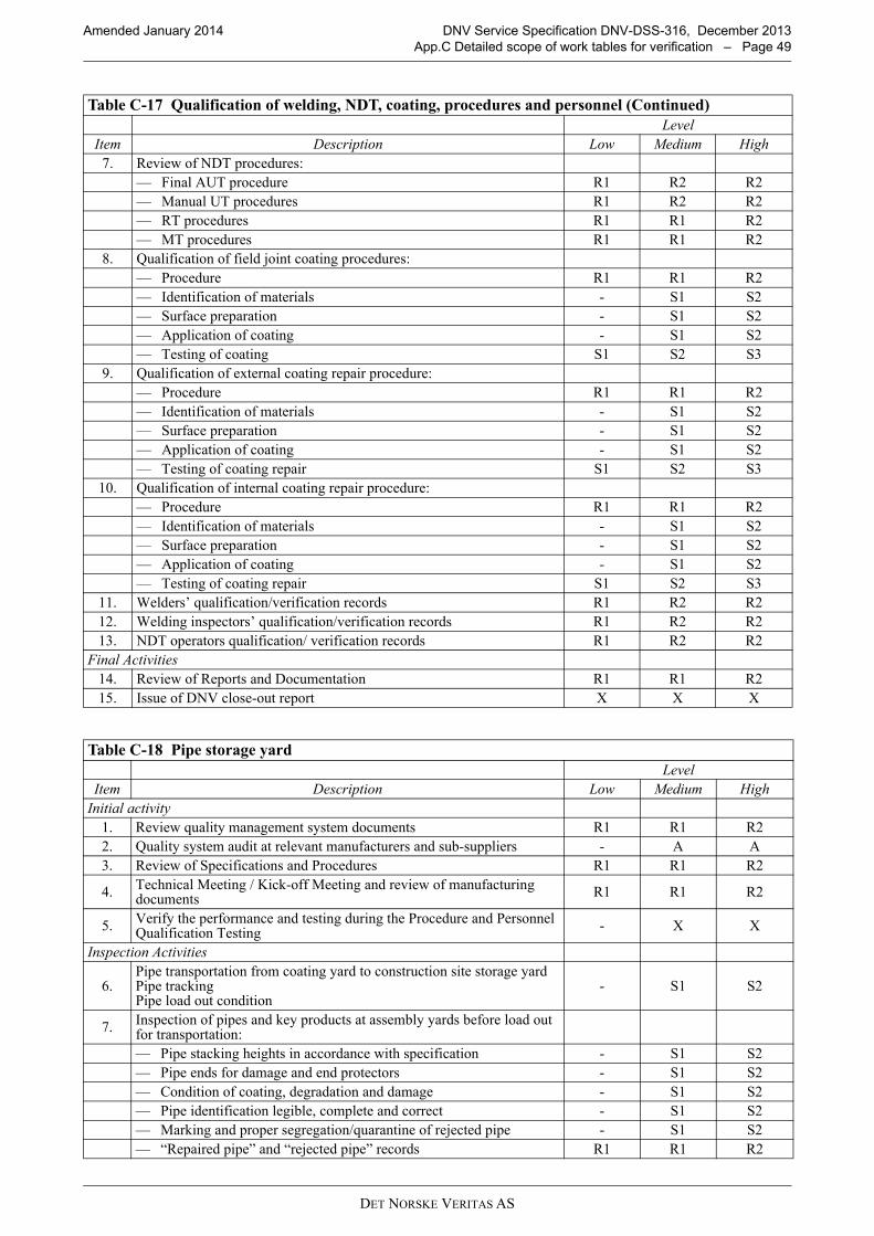
DET NORSKE VERITAS AS
Amended January 2014 DNV Service Specification DNV-DSS-316, December 2013
App.C Detailed scope of work tables for verification – Page 49
7. Review of NDT procedures:
— Final AUT procedure R1 R2 R2
— Manual UT procedures R1 R2 R2
— RT procedures R1 R1 R2
— MT procedures R1 R1 R2
8. Qualification of field joint coating procedures:
— Procedure R1 R1 R2
— Identification of materials - S1 S2
— Surface preparation - S1 S2
— Application of coating - S1 S2
— Testing of coating S1 S2 S3
9. Qualification of external coating repair procedure:
— Procedure R1 R1 R2
— Identification of materials - S1 S2
— Surface preparation - S1 S2
— Application of coating - S1 S2
— Testing of coating repair S1 S2 S3
10. Qualification of internal coating repair procedure:
— Procedure R1 R1 R2
— Identification of materials - S1 S2
— Surface preparation - S1 S2
— Application of coating - S1 S2
— Testing of coating repair S1 S2 S3
11. Welders’ qualification/verification records R1 R2 R2
12. Welding inspectors’ qualification/verification records R1 R2 R2
13. NDT operators qualification/ verification records R1 R2 R2
Final Activities
14. Review of Reports and Documentation R1 R1 R2
15. Issue of DNV close-out report X X X
Table C-18 Pipe storage yard
Level
Item Description Low Medium High
Initial activity
1. Review quality management system documents R1 R1 R2
2. Quality system audit at relevant manufacturers and sub-suppliers - A A
3. Review of Specifications and Procedures R1 R1 R2
4.Technical Meeting / Kick-off Meeting and review of manufacturing documents
R1 R1 R2
5.Verify the performance and testing during the Procedure and Personnel Qualification Testing
- X X
Inspection Activities
6.Pipe transportation from coating yard to construction site storage yardPipe trackingPipe load out condition
- S1 S2
7.Inspection of pipes and key products at assembly yards before load out for transportation:
— Pipe stacking heights in accordance with specification - S1 S2
— Pipe ends for damage and end protectors - S1 S2
— Condition of coating, degradation and damage - S1 S2
— Pipe identification legible, complete and correct - S1 S2
— Marking and proper segregation/quarantine of rejected pipe - S1 S2
— “Repaired pipe” and “rejected pipe” records R1 R1 R2
Table C-17 Qualification of welding, NDT, coating, procedures and personnel (Continued)
Level
Item Description Low Medium High

DET NORSKE VERITAS AS
Amended January 2014 DNV Service Specification DNV-DSS-316, December 2013
App.C Detailed scope of work tables for verification – Page 50
Note: Excavation equipment to be inspected as per Table C-16.
— Internal cleanliness of pipe during storage and prior to shipping - S1 S2
— Verification, documentation and status of pipes in tracking system R1 R1 R2
— Storage condition for key products and welding consumables - S1 S2
8. Cargo manifest, pipe tracking floppy disk and pipe prior to shipping:
— Consistency between Cargo manifest and pipe tracking disk - S1 S2
— No rejected or un-repaired pipes included S1 S1 S2
— Pipe identification correct and legible - S1 S2
— Pipe quantity correct - S1 S2
— Conditions of pipes acceptable to specification - S1 S2
9. Receiving inspection of pipe returned from onshore:
— Segregation of returned pipe S1 S1 S2
— Confirmation of reported reason for rejection - S1 S2
— Inspection for any further damage - S1 S2
— Determine if pipe is repairable - S1 S2
— Marking of pipe as reject or repair - S1 S2
— Entry of rejected pipe in “rejected pipe” records and pipe tracking system
- - X
10. Storage of repairable pipe in storage area:
— Storage in segregated area - S1 S2
— Storage conditions for pipe to be repaired - S1 S2
— Maintenance of “repair” marking - S1 S2
11. Repair of repairable pipe:
— Repair according to accepted procedures S1 S1 S2
— Documentation of repair - S1 S2
— Acceptability of repair - S1 S2
— Correction of “repair” marking - S1 S2
— Correction of status for repaired pipe in the pipe tracking system - - X
Final Activities
12. Review of Reports and Documentation R1 R1 R1
13. Issue of DNV close-out report X X X
Table C-19 Inspection of Excavation Activities
Level
Item Description Low Medium High
1. Trench centre line coordinates according to the latest route plan S1 S2 S3
2. Diversion of the existing drainage according to its procedure - S1 S2
3. Trench profile according to trench drawing - S1 S2
4.Handling of the excavated material according to construction specification
- S1 S2
5.Trench dewatering system operation and maintenance according to its procedure
S1 S2 S3
6. Trench bedding material according to construction specification - S1 S2
7. Bell hole locations and profiles - S1 S2
Final Activities
8. Issue of DNV close-out report X X X
Table C-18 Pipe storage yard (Continued)
Level
Item Description Low Medium High

DET NORSKE VERITAS AS
Amended January 2014 DNV Service Specification DNV-DSS-316, December 2013
App.C Detailed scope of work tables for verification – Page 51
Note: Pipe handling\lifting equipment to be inspected as per Table C-16.
Note: Bending machine to be inspected as per Table C-16.
Table C-20 Inspection of stringing operation
Level
Item Description Low Medium High
1.Pipe transportation from storage yard to installation location according to the procedure
- S1 S2
2.Allowable length of pipes strings along the trench, their distance from trench and from each other, pipe elevation from ground and pipe supports
- S1 S2
3. Pipe tracking records updates - S1 S2
Final Activities
4. Issue of DNV close-out report X X X
Table C-21 Inspection of cold bending operation
Level
Item Description Low Medium High
1.Pipe transportation from storage yard to bending work shop as per the bend list
- S1 S2
2. Pipe handling, coating and pipe ovality checks prior to bending - S1 S2
3. Pipe feeding in to machine and seam weld orientation - S1 S2
4. Bending rate - S1 S2
5.Coating condition, gauge plate test, wrinkles, bend angle and radius checks
S1 S2 S3
6. Rejected bends process according to its procedure - S1 S2
7. Bend load out and transportation to installation site - S1 S2
Final Activities
8. Issue of DNV close-out report X X X
Table C-22 Pipe string welding
Level
Item Description Low Medium High
Initial activity
1. Review quality management system documents R1 R1 R2
2. Quality system audit at relevant manufacturers and sub-suppliers. - A A
3. Review of Specifications and Procedures R1 R1 R2
4.Technical Meeting / Kick-off Meeting and review of manufacturing documents
R1 R1 R2
5.Verify the performance and testing during the Procedure and Personnel Qualification Testing
- X X
Inspection Activities
6. All major equipment is available and ready for use R1 R1 R2
7. All procedures for use during welding and NDT operations are accepted R1 R1 R2
8. Valid verification for welding inspection and NDT personnel R1 R1 R2
9. Pipe receiving inspection and storage:
— Pipe identification legible, complete and correct - S1 S2
— Identification of pipe against certificates - S1 S2
— Identification of welding consumables - S1 S2
10. Receipt of welding consumables and key products:
— Condition acceptable according to specification, packaging undamaged
- S1 S2
— Identification and verification of welding consumables - S1 S2
— Storage conditions for welding consumables - S1 S2
11. Bevelling, cleaning, line-up and welding at welding stations:
— Bevelling and bevel shape - S1 S2
— Internal cleaning - S1 S2

DET NORSKE VERITAS AS
Amended January 2014 DNV Service Specification DNV-DSS-316, December 2013
App.C Detailed scope of work tables for verification – Page 52
Note: Side-booms\lifting machines to be inspected as per Table C-16.
— Line-up and fit-up - S1 S2
— Welding consumables identification, re-cycling of welding flux, mixture of new and re-cycled welding flux (where required)
- S1 S2
— Welding procedures, control of welding parameters S1 S1 S2
— Pipe tracking system entries - - S1
12. Non-destructive testing:
— Calibration blocks - S1 S2
— Equipment calibration - S1 S2
— Scanning - S1 S2
— Interpretation of indications - S1 S2
— Called repairs, location, defect type S1 S1 S2
— Documentation filing - S1 S2
— Equipment maintenance - S1 S2
13. Excavation, welding and NDT of repairs:
— Excavation length and depth, grinding - S1 S2
— NDT of excavation - S1 S2
— Welding consumables identification - S1 S2
— Welding procedures, control of welding parameters - S1 S2
— NDT of repairs S1 S1 S2
14. Production tests:
— Welding of production tests - S1 S2
— NDT of production tests - S1 S2
15. Field joint coating:
— Material and procedure - S1 S2
— Testing of field joint coating - S1 S2
— Confirm filed joint coating integrity after installation (applies to HDD)
S1 S1 S2
16. Pipe tracking – recording of data - - X
Final Activities
17. Review of Reports and Documentation R1 R1 R2
18. Issue of DNV close-out report X X X
Table C-23 Pipe string lowering to trench
Level
Item Description Low Medium High
1. Side-booms\lifting machines arrangements - S1 S2
2. Lifting and lowering operations S1 S1 S2
3. Pipeline position in the trench S1 S1 S2
4. Welding of the pipe string ends and open ends protection caps S1 S2 S3
5. Connection of temporary CP system - - S1
6. Anchor blocking where required - S1 S2
Final Activities
7. Issue of DNV close-out report X X X
Table C-24 Backfilling
Level
Item Description Low Medium High
Initial activity
1. Review quality management system documents R1 R1 R2
2. Quality system audit at relevant manufacturers and sub-suppliers - A A
3. Review of Specifications and Procedures R1 R1 R2
Table C-22 Pipe string welding (Continued)
Level
Item Description Low Medium High

DET NORSKE VERITAS AS
Amended January 2014 DNV Service Specification DNV-DSS-316, December 2013
App.C Detailed scope of work tables for verification – Page 53
4.Technical Meeting / Kick-off Meeting and review of manufacturing documents
R1 R1 R2
5.Verify the performance and testing during the Procedure and Personnel Qualification Testing
- X X
Inspection Activities
6. Backfilling operations - S1 S2
7. Soil Compaction - S1 S2
8. Removing and transportation of the unused excavations into designated areas - - S1
9. Right of cleaning ad soil reinstatement - S1 S2
Final Activities
10. Review of Reports and Documentation R1 R1 R2
11. Issue of DNV close-out report X X X
Table C-25 Pre-commissioning and Commissioning
Level
Item Description Low Medium High
Initial activity
1. Review quality management system documents R1 R1 R2
2. Quality system audit at relevant manufacturers and sub-suppliers. - A A
3. Review of Specifications and Procedures R1 R1 R2
4.Technical Meeting / Kick-off Meeting and review of manufacturing documents
R1 R1 R2
5.Verify the performance and testing during the Procedure and Personnel Qualification Testing
- X X
Inspection Activities
6. Installation of temporary\permanent pig traps - S1 S2
7. Cleaning and gauging pigs - S1 S2
8. Pump and compressor spread - S1 S2
9. Pipe filling, Cleaning and gauging operations - S1 S2
10. System pressure test:
— Water sampling - S1 S2
— Inhibitors - S1 S2
— Water filling - S1 S2
— Instrumentation and equipment calibration R1 R1 R2
— Air contents measurements - S1 S2
— Pressurisation - S1 S2
— Pressure test / holding S1 S1 S2
— Depressurisation - S1 S2
— Dewatering and drying - S1 S2
11. Golden welds S2 S3
12. Connection of permanent CP system, CP test and adjustments - S1 S2
13. Interface connection checks - S1 S2
14. Vent and flare systems - S1 S2
15. Valve operation tests - S1 S2
16. Filling of product - S1 S2
17. Start-up inspection
— Leak Detection System - S1 S2
— SCADA system operation
— Controls and Protective Equipment - S1 S2
— Emergency Plan - S1 S2
Table C-24 Backfilling
Level
Item Description Low Medium High
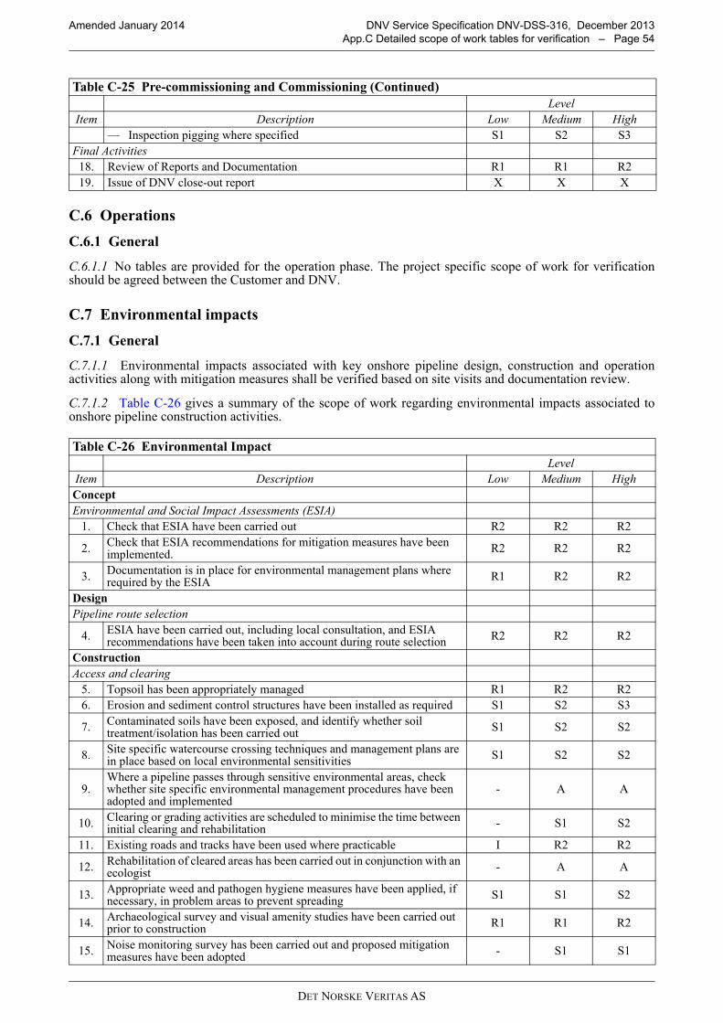
DET NORSKE VERITAS AS
Amended January 2014 DNV Service Specification DNV-DSS-316, December 2013
App.C Detailed scope of work tables for verification – Page 54
C.6 Operations
C.6.1 General
C.6.1.1 No tables are provided for the operation phase. The project specific scope of work for verificationshould be agreed between the Customer and DNV.
C.7 Environmental impacts
C.7.1 General
C.7.1.1 Environmental impacts associated with key onshore pipeline design, construction and operationactivities along with mitigation measures shall be verified based on site visits and documentation review.
C.7.1.2 Table C-26 gives a summary of the scope of work regarding environmental impacts associated toonshore pipeline construction activities.
— Inspection pigging where specified S1 S2 S3
Final Activities
18. Review of Reports and Documentation R1 R1 R2
19. Issue of DNV close-out report X X X
Table C-26 Environmental Impact
Level
Item Description Low Medium High
Concept
Environmental and Social Impact Assessments (ESIA)
1. Check that ESIA have been carried out R2 R2 R2
2.Check that ESIA recommendations for mitigation measures have been implemented.
R2 R2 R2
3.Documentation is in place for environmental management plans where required by the ESIA
R1 R2 R2
Design
Pipeline route selection
4.ESIA have been carried out, including local consultation, and ESIA recommendations have been taken into account during route selection
R2 R2 R2
Construction
Access and clearing
5. Topsoil has been appropriately managed R1 R2 R2
6. Erosion and sediment control structures have been installed as required S1 S2 S3
7.Contaminated soils have been exposed, and identify whether soil treatment/isolation has been carried out
S1 S2 S2
8.Site specific watercourse crossing techniques and management plans are in place based on local environmental sensitivities
S1 S2 S2
9.Where a pipeline passes through sensitive environmental areas, check whether site specific environmental management procedures have been adopted and implemented
- A A
10.Clearing or grading activities are scheduled to minimise the time between initial clearing and rehabilitation
- S1 S2
11. Existing roads and tracks have been used where practicable I R2 R2
12.Rehabilitation of cleared areas has been carried out in conjunction with an ecologist
- A A
13.Appropriate weed and pathogen hygiene measures have been applied, if necessary, in problem areas to prevent spreading
S1 S1 S2
14.Archaeological survey and visual amenity studies have been carried out prior to construction
R1 R1 R2
15.Noise monitoring survey has been carried out and proposed mitigation measures have been adopted
- S1 S1
Table C-25 Pre-commissioning and Commissioning (Continued)
Level
Item Description Low Medium High

DET NORSKE VERITAS AS
Amended January 2014 DNV Service Specification DNV-DSS-316, December 2013
App.C Detailed scope of work tables for verification – Page 55
16.Air quality study has been carried out and proposed mitigation measures adopted for dust minimisation
- S2 S2
17.Relevant equipment such as dust stabilisers or water damping as appropriate have been specified where required
- S2 S2
Pipe Stringing or welding
18.Regular dust monitoring and damping is carried out in accordance with environmental management procedures
- R2 R2
19.Noise monitoring survey has been carried out and proposed mitigation measures have been adopted
- S1 S1
20.Gaps have been allowed during pipe stringing for wildlife corridors, if recommended by an ecologist
- A A
21. Procedures are in place to minimise risk of fire from welding S1 S2 S2
22.Chemicals associated with radiography of pipeline weld are adequately stored and disposed
S1 S2 S2
23.Waste materials are managed appropriately in accordance with a waste plan
S1 S2 S2
Trenching
24. Erosion and sediment control structures as required are in place S1 S2 S3
25.Trench spoil has not been permitted to mix with stockpiled topsoil and vegetation
- S1 S1
26. The length of time trench is open or pipe is exposed has been minimised. - - S2
27.Mitigation measures are in place to prevent wildlife access across the open trench
- A A
28. Backfill has commenced immediately following pipe lay - - S2
29.Blasting or boring operations plan has been developed and implemented to mitigate environmental impacts from blasting
S1 S1 S1
Directional drilling
30. Waste has been managed appropriately in accordance with a waste plan S1 S2 S2
31.Noise monitoring survey has been carried out and proposed mitigation measures have been adopted
- S2 S2
32. Environmental impacts from increased workforce have been minimised - R1 R2
Pipe laying and backfilling
33.Top soil protection and erosion prevention measures have been adopted as required
R1 R2 R2
34.Monitoring of discharge water quality has been carried out and appropriate discharge options identified
S2 S2 S3
35.Trench blocks have been used if required and compaction of soil has been carried out if required
- S1 S1
36.Potential impacts on migratory patterns of species have been considered for above ground pipes
- I R1
37.Adequate management systems are in place for solid, liquid and hazardous wastes following backfilling
S1 S1 S2
Construction camps and storage facilities
38. The environmental impacts of building construction have been minimised A A A
Commissioning
Hydrostatic testing
39.Water used for hydrotesting is discharged under an environment (waste discharge) permit or equivalent
S1 S1 S1
40. Appropriate treatment methods are adopted prior to discharge S1 S1 S1
41.Resource availability study has been carried out to identify and mitigate any third party deprivation
- R1 R2
42.Measures are in place to avoid transfer of species from one catchment to another
A A A
Pigging and gas venting
43.An appropriate emissions assessment has been carried out if gas venting is required
S1 S2 S2
Table C-26 Environmental Impact (Continued)
Level
Item Description Low Medium High

DET NORSKE VERITAS AS
Amended January 2014 DNV Service Specification DNV-DSS-316, December 2013
App.C Detailed scope of work tables for verification – Page 56
C.8 Third party safety impact assessment
C.8.1 General
C.8.1.1 The requirements for 3rd Party Safety Impact Assessments (3PSIA) of onshore pipelines depend onthe local regulatory regime and the operator’s internal risk management requirements. They can vary fromqualitative assessment through to full Quantitative Risk Analysis (QRA). Many Activities summarized in theTable C-27 below are to be undertaken irrespective of the requirements. Specific requirements for verificationof 3PSIAs are included as a single activity and are worded either to be applicable irrespective of therequirements for a 3PSIA or else to be clearly applicable only to a certain type or certain types of 3PSIA.
C.8.1.2 A qualitative 3PSIA would typically include a Hazard Identification (HAZID) study, which shouldidentify all planned risk control measures (sometimes referred to as “barriers” – physical and procedural) andmay recommend additional risk control measures. Risk ranking (expert judgment-based assessment oflikelihood and impact, in broad categories) would typically be included as part of this.
C.8.1.3 Where quantitative analysis is required, this may involve numerical modelling of the consequences ofa loss of containment incident and may further involve calculation of numerical values of risk (combiningfrequency estimates with the consequence modelling results). In some regulatory regimes, however (e.g. UK),separation distances have previously been established for natural gas pipelines: conformance to these is deemedto meet the applicable risk criteria.
C.8.1.4 Table C-27 gives a summary of the scope of work table included in this section various onshorepipeline construction activities regarding 3PSIA.
44.Noise monitoring survey has been carried out and proposed mitigation measures have been adopted
- S1 S1
45. Leakage monitoring is carried out to detect gas leakage S2 S3 S3
Operation
Pipeline maintenance
46. Access related impacts have been minimised S1 S1 S1
47.Erosion and sediment controls are installed in accordance with best practice and measures are in place for routine checks, particularly at watercourse crossings
S1 S1 S1
48. Issue of DNV close-out report X X X
Table C-27 3rd Party Safety Impacts (3PSIA)
Level
Item Description Low Medium High
Concept
Regulatory requirements
1.Regulatory requirements for 3PSIA have been identified and appropriate studies commissioned
R1 R2 R2
Design
Pipeline route selection
2.3PSIA has been carried out and route has been selected to minimize overall 3PSI
R1 R2 R2
3.Local consultation has been carried out and conclusions have been addressed in route planning
R1 R1 R1
4.Sensitive areas (e.g. schools, hospitals) have been identified and taken into account in route planning
R2 R2 R2
5.3rd party activities above or in the vicinity of the pipeline (e.g. agricultural activities such as ploughing) that could cause immediate pipeline damage have been identified
R1 R2 R2
6.Activities (e.g. road traffic on route crossing pipeline) that could cause pipeline degradation have been identified
R1 R2 R2
7.3rd party activities in the vicinity of the pipeline that could cause escalation of an initial incident (e.g. ignition of flammable gas) have been identified
R1 R2 R2
Table C-26 Environmental Impact (Continued)
Level
Item Description Low Medium High

DET NORSKE VERITAS AS
Amended January 2014 DNV Service Specification DNV-DSS-316, December 2013
App.C Detailed scope of work tables for verification – Page 57
8.Potential safety impacts of pipeline construction activities on 3rd parties have been identified
R1 R2 R2
9.Influence of material density, topography and barriers on loss of containment events established and understood
R1 R2 R2
10. Emergency access e.g. to section valves available R2 R2 R2
Design factors
11.Suitable design factors applied throughout pipeline route, in particular at vulnerable locations such as road crossings, and basis for selection documented
R1 R2 R2
Protection against impact
12.Appropriate burial depths have been specified along the entire pipeline route
R1 R2 R2
13.Protection above (e.g. concrete slabs) has been considered and specified as and where appropriate
R1 R1 R2
14. Culverting of the pipeline at road/rail crossings has been considered R1 R2 R2
Ground movement
15.Potential magnitude of seismic activity along pipeline route has been evaluated and pipeline designed to maintain integrity in credible seismic events
R1 R2 R2
16.Potential for landslip has been evaluated along pipeline route and stabilization of ground specified where evaluation identifies it is required
R1 R2 R2
Incident control
17. Detecting Loss of Containment reviewed and implemented if practical R1 R2 R2
18. Raising alarm to emergency services local to incident implemented R1 R2 R2
19. Minimizing released inventory R1 R2 R2
Process design
20. Operating envelope has been defined and documented R1 R2 R2
3PSIA
21.Suitable hazard identification study carried out, including identification of planned risk controls
R1 R2 R2
22.Appropriate failure scenarios have been assessed/modelled (for a range of sizes and release directions)
R1 R2 R2
23.Appropriate modelling (if used) of physical features of each release scenario (released material, size, direction, isolation, pipeline depressurization) has been applied
R1 R2 R2
24.Qualitative understanding of potential consequences of each release scenario is demonstrated
R1 R2 R2
25.Qualitative understanding of 3PSI of consequences of each release scenario is demonstrated
R1 R2 R2
26.Local meteorological data (weather conditions, wind direction) has been used
R1 R2 R2
27.Recognized models (if models used) have been used for consequences of each release scenario
R1 R2 R2
28.All credible outcomes of each release scenario have been modelled (if models used)
R1 R2 R2
29.If risk based 3PSIA used: suitable spacing of scenarios along pipeline has been used
R1 R2 R2
30.If risk based 3PSIA used: modelling of entire route, of appropriate representative sections, or of an appropriate combination of the two, has been applied
R1 R2 R2
31. If risk based approach adopted, appropriate risk criteria have been applied R1 R2 R2
32.If risk based 3PSIA used: dominant scenarios and outcomes (largest risk contributors), for both individual and societal risk, have been identified
R1 R2 R2
33. Uncertainties in quantitative results have been estimated R1 R2 R2
34.Locations where quantitative models may not fully represent 3PSI (e.g. due to topography) have been identified and their effect on 3PSI discussed
- A A
Table C-27 3rd Party Safety Impacts (3PSIA) (Continued)
Level
Item Description Low Medium High

DET NORSKE VERITAS AS
Amended January 2014 DNV Service Specification DNV-DSS-316, December 2013
App.C Detailed scope of work tables for verification – Page 58
Construction
Pipeline Route
35. Pipeline route clearly marked S1 S2 S2
Commissioning
Incident control
36. Detecting Loss of Containment S1 S1 S1
37. Raising alarm to emergency services local to incident operational S1 S1 S1
38. Minimizing released inventory S1 S1 S1
39. Pipeline route marks clearly visible A A A
40. Issue of DNV close-out report X X X
Table C-27 3rd Party Safety Impacts (3PSIA) (Continued)
Level
Item Description Low Medium High