
DNP V3.00 DATA LINK LAYER - search...
291
DNP Users Group DNP PRODUCT DOCUMENTATION DNP V3.00 DATA LINK LAYER Document Version: 0.02 Internal File: P009-0PD.DL Associated Software Release: DNP V3.00
Transcript of DNP V3.00 DATA LINK LAYER - search...

DNP Users Group
DNP PRODUCT DOCUMENTATION
DNP V3.00DATA LINK LAYER
Document Version: 0.02Internal File: P009-0PD.DL
Associated Software Release: DNP V3.00

NOTICE OF RIGHTS - DNP USERS GROUP
The contents of this manual are the property of the DNP UsersGroup. Revisions or additions to the definition and functionality ofthe Distributed Network Protocol cannot be made without expresswritten agreement from the DNP Users Group or its duly authorizedparty. In addition, no part of this document may be altered orrevised or added to in any form or by any means, except as permittedby written agreement with the DNP Users Group or a Party dulyauthorized by the DNP Users Group.
As a Party, duly authorized by the DNP Users Group, HarrisCorporation has made every reasonable attempt to ensure thecompleteness and accuracy of this document, however, theinformation contained in this manual is subject to change withoutnotice, and does not represent a commitment on the part of HarrisCorporation or the DNP Users Group. An update program for DNPdocuments is provided upon request by Harris Corporation onbehalf of the DNP Users Group.
TRADEMARK NOTICES
Brand and product names mentioned in this document aretrademarks or registered trademarks of their respective companies.

DNP V3.00 Data Link Layer (Version 0.02) i
TABLE OF CONTENTS
ABOUT THIS DOCUMENT IVPURPOSE OF THIS SPECIFICATION ivWHO SHOULD USE THIS SPECIFICATION ivHELP AND ADDITIONAL DOCUMENTATION ivHOW THIS SPECIFICATION IS ORGANIZED vCONVENTIONS USED IN THIS SPECIFICATION v
1. OVERVIEW 1-1
2. IEC CONFORMANCE 2-12.1 CHANNEL FAILOVER 2-12.2 FRAME FORMAT AND PROCEDURES 2-12.3 LENGTH, CONTROL AND ADDRESS FIELDS 2-1
3. DNP DATA LINK DESCRIPTION 3-13.1 PURPOSE OF THE DATA LINK LAYER 3-13.2 FT3 FRAME FORMAT 3-13.3 DATA LINK HEADER FRAME FIELDS 3-23.4 USER DATA 3-53.5 CRC FIELDS 3-53.6 DATA LINK FUNCTION CODES 3-63.7 TRANSMISSION PROCEDURES 3-8
4. DATA LINK SERVICES AND RESPONSIBILITIES 4-14.1 DATA LINK FUNCTIONS 4-14.2 INTERFACE DESCRIPTION 4-1
5. PHYSICAL LAYER INTERFACE 5-15.1 PHYSICAL LAYER DESCRIPTION 5-1
6. PHYSICAL LAYER CHARACTERISTICS 6-16.1 LINE CONFIGURATIONS 6-16.2 MODES OF TRANSMISSION 6-16.3 LOCAL LOOP 6-1
7. PHYSICAL LAYER PROCEDURES 7-17.1 GENERAL CONSIDERATIONS 7-17.2 HALF-DUPLEX PROCEDURES 7-17.3 FULL-DUPLEX PROCEDURES 7-2
LIST OF ABBREVIATIONS AND ACRONYMS 1

DNP Users Groupii
TABLE OF FIGURES
FIGURE 3-1 FT3 FRAME FORMAT 3-2FIGURE 3-2 CONTROL OCTET BIT DEFINITIONS 3-3FIGURE 3-3 TABLE OF PRIMARY AND SECONDARY FUNCTION CODES 3-4FIGURE 3-4 DESTINATION ADDRESS FORMAT 3-4FIGURE 3-5 SOURCE ADDRESS FORMAT 3-5FIGURE 3-6 CRC ORDERING 3-6FIGURE 3-7 RESET OF SECONDARY LINK 3-8FIGURE 3-8 RESET OF USER PROCESS 3-9FIGURE 3-9 SEND FROM STATION A/CONFIRM FROM STATION B 3-9FIGURE 3-10 SEND FROM STATION B/CONFIRM FROM STATION A 3-9FIGURE 3-11 SEND MULTIPLE FRAMES FROM STATION A/CONFIRM FROM STATION B 3-10FIGURE 3-12 FRAME COUNT BIT OPERATION 3-10FIGURE 3-13 FRAME COUNT BIT OPERATION 3-10FIGURE 3-14 SEND-NO-REPLY EXPECTED FROM STATION A 3-11FIGURE 3-15 SEND FROM STATION B/NACK FROM STATION A 3-11FIGURE 3-16 REQUEST/RESPOND FRAME AND DFC BIT USAGE 3-12

DNP V3.00 Data Link Layer (Version 0.02) iii
DNP Users Groupiv
ABOUT THIS DOCUMENT
PURPOSE OF THIS SPECIFICATION
This document specifies the Distributed Network Protocol (DNP) Data Link layer services,transmission procedures and Link Protocol Data Unit.
WHO SHOULD USE THIS SPECIFICATION
This specification is intended for communication engineers and programmers interested in knowing thefunction and message format of the DNP data link layer. This includes programmers implementing anddesigning DNP data link layer software/hardware and quality assurance personnel testing and verifyingimplementations of the DNP data link layer. Application programmers may find this specificationuseful in determining how to interface with and make use of the DNP data link layer. Familiarity withthe ISO-OSI 7-layer model, IEC 3-layer EPA and IEC TC-57 standards is helpful.
HELP AND ADDITIONAL DOCUMENTATION
The following documentation may be helpful.• IEC 870-5-1 and IEC 870-5-2 standards (or drafts), Technical Committee No. 57 for data
transmission in telecontrol systems• DNP V3.00 Data Object Library (P009-0BL)• DNP V3.00 Application Layer (P009-0PD.APP)• DNP V3.00 Transport Functions (P009-0PD.TF).

DNP V3.00 Data Link Layer (Version 0.02) v
HOW THIS SPECIFICATION IS ORGANIZED
1. OVERVIEWA general overview of the data link layer.
2. IEC CONFORMANCEDetails the differences between DNP and the IEC TC-57 standards.
3. DNP DATA LINK DESCRIPTIONDescribes the DNP data link frame format, function codes and procedures.
4. DATA LINK SERVICES AND RESPONSIBILITIESDescribes the services that the data link provides to higher layers.
5. PHYSICAL LAYER INTERFACEDescribes the service interface provided by the physical layer to the data link.
6. PHYSICAL LAYER CHARACTERISTICSDescribes the physical layer used with the DNP data link.
7. PHYSICAL LAYER PROCEDURESDescribes how the DNP data link uses the physical layer.
LIST OF ABBREVIATIONS AND ACRONYMS
CONVENTIONS USED IN THIS SPECIFICATION
In this document, the octet is a term used to refer to an eight bit data object and is synonymous with theterm byte. The low order bit of an octet is referred to as bit 0 and the high order bit as bit 7.
Irregular capitalization is used in referencing technical terms which have an associated verb or noun.For example, data link indications commonly referred to as IND, can also be described using the wordINDication.


DNP V3.00 Data Link Layer (Version 0.02) 1-1
1. OVERVIEW
This document defines the Distributed Network Protocol (DNP) V3.00 Data Link layer, Link ProtocolData Unit (LPDU), as well as data link layer services and transmission procedures. Master stations,submaster stations, outstations and intelligent electronic devices (IEDs) can use this data link to passmessages between primary (originating) stations and secondary (receiving) stations. In this protocol,master stations, submaster stations, outstations and IEDs are both originators (primary stations) andreceivers (secondary stations).
The IEC 870-5-1 and IEC 870-5-2 standards set out by the International Electrotechnical Commission(IEC), Technical Committee No. 57 for data transmission in telecontrol systems were used as a basis fordeveloping the DNP V3.00 Data Link layer.
The DNP V3.00 Data Link layer supports polled and quiescent telecontrol systems and is designed tooperate with connection and connection-less orientated, asynchronous or synchronous bit-serialphysical layers such as RS-232C, RS-485 and fibre transceivers. Fully-balanced transmissionprocedures were adopted to support spontaneous transmissions from outstations, IEDs or submasterstations not designated as master stations.
The ISO OSI based model supported by this protocol specifies physical, data link and application layersonly. This is termed the Enhanced Performance Architecture (EPA). However, to support advancedRTU functions and messages larger than the maximum frame length as defined by the IEC document870-5-1, the DNP Version 3 Data Link is intended to be used with a pseudo-transport layer whichimplements as a minimum message assembly and disassembly.
This pseudo-transport layer is described in the document, DNP V3.00 Transport Functions (P009-0PD.TF). It is stressed, however, that these transport functions are not a part of the data link but areneeded to support advanced RTU functions.


DNP V3.00 Data Link Layer (Version 0.02) 2-1
2. IEC CONFORMANCE
This chapter describes the difference between the DNP protocol and the IEC TC-57 (870-5) telecontroldata link layer protocol specification.
2.1 CHANNEL FAILOVER
The DNP link layer communicates with only one physical layer (or channel). In the OSI model, theSession layer is responsible for maintaining channel connections. In DNP, the layer above the data linkis responsible for providing channel failover based on communications failure at the Data Link. Thislayer could be a Network/Transport Layer or the Application Layer. Thus, the IEC requirement, 870-5-1, item 13, for channel failover is met at the Application Layer.
2.2 FRAME FORMAT AND PROCEDURES
The data link layer uses a standard variable length frame format as defined in the IEC 870-5-1Transmission Frame Formats document. The FT3 frame format class is well suited for datatransmission between stations that require medium information transfer rates and low residual errorprobability. The basic frame format is used and transmission rules R1, R2, R3 and R4 are followed.Rules R5 and R6 are followed in principle, although the exact time values suggested are not used butare configurable in each implementation. The frame definitions outlined in IEC 870-5-2 are followedwith the note that !"#$%&&'#(($)*#+&$*($,$-.!#!($*/$+#/0!"$1/&$(2#.*)*#($!"#$&#(!*/1!*-/$(!1!*-/$1&&'#((1/&$!"#$3*/4$5(#'$61!1$)*#+&$*($7(#&$1($1$,$-.!#!$(-7'.#$(!1!*-/$1&&'#((8
Fully-balanced transmission procedures as specified by IEC 870-5-2 were adopted to handle unsolicitedtransmissions from stations not designated as masters in a half-duplex or full-duplex system. Fully-balanced means that each station can act as a primary station (sending) and a secondary station(receiving) at the same time. This configuration requires a full-duplex channel to operate properly. In ahalf-duplex environment, the same procedures will be used except that a station cannot be both aprimary and secondary station at the same time. That is, an entire data link layer transaction between themaster station and outstation will have to be completed at both stations before any further transactionscan be started from either station. In both half-duplex and full-duplex configurations, it is theresponsibility of each device to implement a compatible collision avoidance scheme.
2.3 LENGTH, CONTROL AND ADDRESS FIELDS
The DNP data link uses the same LENGTH field as defined in IEC 870-5-1 clause 6.2.4. (Refer toSection 3 for more information on this field).
The CONTROL field used is the IEC CONTROL field used for balanced transmission as defined inIEC 870-5-2 clause 6.1.2. All the function codes specified in IEC 870-5-3 clause 6.1.2 Table III aresupported.
The ADDRESS field is a 16-bit (2 octet) field. The DNP data link frame header has two IECADDRESS fields. The first field is the A (Address) field where it is used to represent the destinationstation address and the second is in the Link User Data field where it is used to represent the sourcestation address. (Refer to Section 3 for more information on these fields).

DNP V3.00 Data Link Layer (Version 0.02) 3-1
3. DNP DATA LINK DESCRIPTION
The Data Link Layer is the second layer in the Open System Interconnection (OSI) model. The datalink layer accepts, performs and controls transmission service functions required by the higher layers.
3.1 PURPOSE OF THE DATA LINK LAYER
The main purpose of the DNP data link layer is twofold. First, the data link layer must provide transferof information or Link Service Data Unit (LSDU) across the physical link as described by the ISO-OSIstandard. This means that user data supplied by higher layers (LSDU) must be converted into one frame(or LPDU as described in Section 2) and sent to the physical layer for transmission. Conversely,individual LPDUs received by the data link layer must be assembled into one LSDU and passed tohigher layers. The layer provides for frame synchronization and link control.
Secondly, in DNP V3.00, the data link provides indications of other events such as link status.
The OSI reference model enforces either a connection-less or a connection oriented system. However,the EPA model implies neither a connection-less system nor a connection oriented system. The DNPVersion 3 implementation of the IEC data link handles both connection-less and connection orientedsystems (that is, physical networks that require dialing or logging in before data can be transmitted tothe destination device) but has no need to provide connection services. The actual physical network istransparent to the application using the data link because the data link layer is responsible forconnecting and disconnecting from any physical network without higher level interaction (i.e.application layer). That is, the data link (given the station destination address) will connect to the rightphysical circuit without control supplied from higher layers. In this way, the physical medium is totallytransparent to the link layer service user.
3.2 FT3 FRAME FORMAT
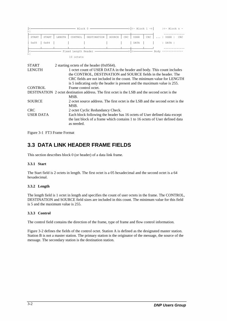
This section describes the LPDU format. An FT3 frame is defined as a fixed length header blockfollowed by optional data blocks. Each block has a 16-bit CRC appended to it. The IEC specifies thatthe header fields consist of 2 start octets, 1 octet length, 1 octet control, a destination address and anoptional fixed length user data field. In this implementation the fixed length user data field is defined asa source address.
DNP Users Group3-2
│<──────────────────────────── Block 0 ────────────────────────>│<- Block 1 ->│ |<- Block n ->|├───────┬───────┬────────┬─────────┬─────────────┬────────┬─────┼───────┬─────┤ -------------│ START │ START │ LENGTH │ CONTROL │ DESTINATION │ SOURCE │ CRC │ USER │ CRC │ ... | USER | CRC|│ 0x05 │ 0x64 │ │ │ │ │ │ DATA │ │ | DATA | |├───────┴───────┴────────┴─────────┴─────────────┴────────┴─────┼───────┴─────┘ -------------│<─────────────────── Fixed Length Header ─────────────────────>│<──────────── Body ------------->| 10 octets
START 2 starting octets of the header (0x0564).LENGTH 1 octet count of USER DATA in the header and body. This count includes
the CONTROL, DESTINATION and SOURCE fields in the header. TheCRC fields are not included in the count. The minimum value for LENGTHis 5 indicating only the header is present and the maximum value is 255.
CONTROL Frame control octet.DESTINATION 2 octet destination address. The first octet is the LSB and the second octet is the
MSB.SOURCE 2 octet source address. The first octet is the LSB and the second octet is the
MSB.CRC 2 octet Cyclic Redundancy Check.USER DATA Each block following the header has 16 octets of User defined data except
the last block of a frame which contains 1 to 16 octets of User defined dataas needed.
Figure 3-1 FT3 Frame Format
3.3 DATA LINK HEADER FRAME FIELDS
This section describes block 0 (or header) of a data link frame.
3.3.1 Start
The Start field is 2 octets in length. The first octet is a 05 hexadecimal and the second octet is a 64hexadecimal.
3.3.2 Length
The length field is 1 octet in length and specifies the count of user octets in the frame. The CONTROL,DESTINATION and SOURCE field sizes are included in this count. The minimum value for this fieldis 5 and the maximum value is 255.
3.3.3 Control
The control field contains the direction of the frame, type of frame and flow control information.
Figure 3-2 defines the fields of the control octet. Station A is defined as the designated master station.Station B is not a master station. The primary station is the originator of the message, the source of themessage. The secondary station is the destination station.

DNP V3.00 Data Link Layer (Version 0.02) 3-3
┌─────┬─────┬─────┬─────┬─────┬─────┬─────┬─────┐ │ │ 1 │ FCB │ FCV │ │ │ │ │ Primary to Secondary │ DIR │ PRM ├─────├─────┤ FUNCTION CODE │ │ │ 0 │ RES │ DFC │ │ │ │ │ Secondary to Primary └─────┴─────┴─────┴─────┴─────┴─────┴─────┴─────┘Bit 7 6 5 4 3 2 1 0
DIR Physical transmission direction1 = station A to station B0 = station B to station A
PRM Primary Message1 = frame from primary (initiating station)0 = frame from secondary (responding station)
FCB Frame count bit
FCV Frame count bit valid1 = Frame count bit is valid0 = ignore frame count bit
DFC Data flow control bit
RES Reserved = 0
FUNCTION CODE Defines the frame type, how the data link will handle the frame
Figure 3-2 Control Octet Bit Definitions
DIR The direction bit indicates the physical direction of the frame with relation to the designatedmaster station. Station A is the master.DIR = 1 indicates a frame from A to BDIR = 0 indicates a frame from B to A
PRM The primary message bit indicates the direction of the frame in relation to the initiating station.PRM =1 indicates a frame from the initiating stationPRM =0 indicates a frame from the responding station.
FCB The frame count bit is used for suppressing losses and duplication of frames to the samesecondary station. This bit toggles for each successful SEND-CONFIRM service that isinitiated by the same primary station and directed to the same secondary station.Initially before communications with a secondary station or after communication failure, theprimary station (in both the master station and outstation) must reset the data link for eachsecondary station data link it wishes to communicate with. This can be done once at data linkstart-up for all secondary stations or as needed.Each secondary station, after data link start-up or transaction failure, must not accept anyprimary SEND-CONFIRM messages with FCV set until a RESET command has been receivedand a CONFIRM message sent.
FCV The frame count valid bit enables the functioning of the FCB bit.FCV =0 indicates the state of the FCB bit is ignoredFCV =1 indicates to a secondary station that the state of the FCB bit must be checked againstthe state of the FCB bit of the last frame sent with the FCV bit set.
DFC The data flow control bit is used to prevent the overflowing of buffers in a secondary station.The secondary station returns this bit set to a 1 if further SEND of user data to this secondarystation will cause data link buffers to over flow. The primary station must interrogate thesecondary station using REQUEST-RESPOND Request Link Status until the DFC is returnedwith a value of 0. At this point the primary station can continue with the sending of user data.Figure 3-16 illustrates the DFC bit usage.

DNP Users Group3-4
FUNCTION CODE The function code identifies the type of frame. The definition of the valuesplaced in this field are different between primary and secondary stations.The following tables define the implemented codes and associated FCVstates.
Function Code Field Values of the Control Octet Sent from the Primary Station (PRM = 1)
┌──────────┬─────────────────────────────┬──────────────────────────┬─────┐│ Function │ Frame Type │ Service Function │ FCV ││ Code │ │ │ Bit │├──────────┼─────────────────────────────┼──────────────────────────┼─────┤│ 0 │ SEND - CONFIRM expected │ RESET of remote link │ 0 ││ 1 │ SEND - CONFIRM expected │ Reset of user process │ 0 ││ 2 │ SEND - CONFIRM expected │ TEST function for link │ 1 ││ 3 │ SEND - CONFIRM expected │ User Data │ 1 ││ 4 │ SEND - NO REPLY expected │ Unconfirmed User Data │ 0 ││ 5 │ │ Not Used │ - ││ 6 │ │ Not used │ - ││ 7 │ │ Not Used │ - ││ 8 │ │ Not Used │ - ││ 9 │ REQUEST - RESPOND expected │ REQUEST LINK STATUS │ 0 ││ 10 │ │ Not Used │ - ││ 11 │ │ Not Used │ - ││ 12 │ │ Not Used │ - ││ 13 │ │ Not Used │ - ││ 14 │ │ Not Used │ - ││ 15 │ │ Not Used │ - ││ │ │ │ ││ │ │ │ │└──────────┴─────────────────────────────┴──────────────────────────┴─────┘
Function Code Field Values of the Control Octet Sent from the Secondary Station (PRM = 0)
┌──────────┬─────────────┬──────────────────────────────────────────┐│ Function │ Frame Type │ Service Function ││ Code │ │ │├──────────┼─────────────┼──────────────────────────────────────────┤│ 0 │ CONFIRM │ ACK - positive acknowledgement ││ 1 │ CONFIRM │ NACK - Message not accepted, Link busy ││ 2 │ │ Not Used ││ 3 │ │ Not Used ││ 4 │ │ Not Used ││ 5 │ │ Not Used ││ 6 │ │ Not Used ││ 7 │ │ Not Used ││ 8 │ │ Not Used ││ 9 │ │ Not Used ││ 10 │ │ Not Used ││ 11 │ RESPOND │ Status of Link (DFC = 0 or DFC = 1) ││ 12 │ │ Not Used ││ 13 │ │ Not Used ││ 14 │ │ Link service not functioning ││ 15 │ │ Link service not used or implemented │└──────────┴─────────────┴──────────────────────────────────────────┘
Figure 3-3 Table of Primary and Secondary Function Codes
3.3.4 Destination Address
The Destination address field is 2 octets in size and specifies the address of the station that the frame isdirected to. The first octet of the address is the low order octet and the second octet is the high order.
The address 0xffff is defined as an all stations address. All stations will accept frames with thedestination address set to this value.
┌────────────────────────────┬──────────────────────────┐ │ │ │ │ LOW ORDER OCTET (LSB) │ HIGH ORDER OCTET (MSB) │ │ │ │ └────────────────────────────┴──────────────────────────┘
Figure 3-4 Destination Address Format
3.3.5 Source Address
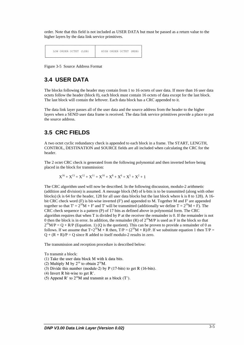
The source address field is 2 octets in size and specifies the address of the station that the frameoriginated from. The first octet of the address is the low order octet and the second octet is the high
DNP V3.00 Data Link Layer (Version 0.02) 3-5
order. Note that this field is not included as USER DATA but must be passed as a return value to thehigher layers by the data link service primitives.
┌────────────────────────────┬──────────────────────────┐│ │ ││ LOW ORDER OCTET (LSB) │ HIGH ORDER OCTET (MSB) ││ │ │└────────────────────────────┴──────────────────────────┘
Figure 3-5 Source Address Format
3.4 USER DATA
The blocks following the header may contain from 1 to 16 octets of user data. If more than 16 user dataoctets follow the header (block 0), each block must contain 16 octets of data except for the last block.The last block will contain the leftover. Each data block has a CRC appended to it.
The data link layer passes all of the user data and the source address from the header to the higherlayers when a SEND user data frame is received. The data link service primitives provide a place to putthe source address.
3.5 CRC FIELDS
A two octet cyclic redundancy check is appended to each block in a frame. The START, LENGTH,CONTROL, DESTINATION and SOURCE fields are all included when calculating the CRC for theheader.
The 2 octet CRC check is generated from the following polynomial and then inverted before beingplaced in the block for transmission:
X16 + X13 + X12 + X11 + X10 + X8 + X6 + X5 + X2 + 1
The CRC algorithm used will now be described. In the following discussion, modulo-2 arithmetic(addition and division) is assumed. A message block (M) of k-bits is to be transmitted (along with otherblocks) (k is 64 for the header, 128 for all user data blocks but the last block where k is 8 to 128). A 16-bit CRC check word (F) is bit-wise inverted (F') and appended to M. Together M and F' are appendedtogether so that T' = 216M + F' and T' will be transmitted (additionally we define T = 216M + F). TheCRC check sequence is a pattern (P) of 17 bits as defined above in polynomial form. The CRCalgorithm requires that when T is divided by P at the receiver the remainder is 0. If the remainder is not0 then the block is in error. In addition, the remainder (R) of 216M/P is used as F in the block so that216M/P = Q + R/P (Equation. 1) (Q is the quotient). This can be proven to provide a remainder of 0 asfollows. If we assume that T=216M + R then, T/P = (216M + R)/P. If we substitute equation 1 then T/P =Q + (R + R)/P = Q since R added to itself modulo-2 results in zero.
The transmission and reception procedure is described below:
To transmit a block:9:; <14#$!"#$7(#'$&1!1$=+-.4$>$?*!"$4$&1!1$=*!(89,; >7+!*2+@$>$=@$,:A$!-$-=!1*/$,:A>89B; 6*C*&#$!"*($/7D=#'$9D-&7+#E,;$=@$F$9:GE=*!(;$!-$0#!$H$9:AE=*!(;89I; J/C#'!$H$=*!E?*(#$!-$0#!$HK89L; %22#/&$HK$!-$,:A>$1/&$!'1/(D*!$1($1$=+-.4$9<K;8
DNP Users Group3-6
To receive a block:9:; H#.#*C#$1$=+-.4$9<K;$94M:A$=*!(;89,; J/C#'!$HK9:AE=*!(;$*/$<K94M:A$=*!(;$!-$0#!$<$94M:A$=*!(;89B; 6*C*&#$<$9D-&7+#E,;$=@$F$9:GE=*!(;$!-$0#!$!"#$'#D1*/&#'89I; J)$!"#$'#D1*/&#'$*($/-!$N$!"#/$!"#'#$*($1/$#''-'$*/$!"#$=+-.4$#+(#$!"#$=+-.4$*($0--&8
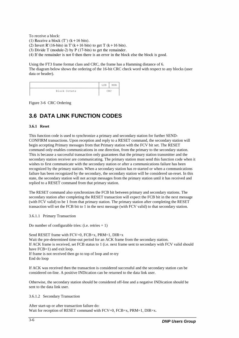
Using the FT3 frame format class and CRC, the frame has a Hamming distance of 6.The diagram below shows the ordering of the 16-bit CRC check word with respect to any blocks (userdata or header).
┌────────────────────────────────────────┬─────┬─────┐│ │ LSB │ MSB │├────────────────────────────────────────┼─────┴─────┤│ Block Octets │ CRC ││ │ │
Figure 3-6 CRC Ordering
3.6 DATA LINK FUNCTION CODES
3.6.1 Reset
This function code is used to synchronize a primary and secondary station for further SEND-CONFIRM transactions. Upon reception and reply to a RESET command, the secondary station willbegin accepting Primary messages from that Primary station with the FCV bit set. The RESETcommand only enables communications in one direction, from the primary to the secondary station.This is because a successful transaction only guarantees that the primary station transmitter and thesecondary station receiver are communicating. The primary station must send this function code when itwishes to first communicate with the secondary station or after a communications failure has beenrecognized by the primary station. When a secondary station has re-started or when a communicationsfailure has been recognized by the secondary, the secondary station will be considered un-reset. In thisstate, the secondary station will not accept messages from the primary station until it has received andreplied to a RESET command from that primary station.
The RESET command also synchronizes the FCB bit between primary and secondary stations. Thesecondary station after completing the RESET transaction will expect the FCB bit in the next message(with FCV valid) to be 1 from that primary station. The primary station after completing the RESETtransaction will set the FCB bit to 1 in the next message (with FCV valid) to that secondary station.
3.6.1.1 Primary Transaction
Do number of configurable tries: (i.e. retries + 1)
Send RESET frame with FCV=0, FCB=x, PRM=1, DIR=xWait the pre-determined time-out period for an ACK frame from the secondary station.If ACK frame is received, set FCB status to 1 (i.e. next frame sent to secondary with FCV valid shouldhave FCB=1) and exit loop.If frame is not received then go to top of loop and re-tryEnd do loop
If ACK was received then the transaction is considered successful and the secondary station can beconsidered on-line. A positive INDication can be returned to the data link user.
Otherwise, the secondary station should be considered off-line and a negative INDication should besent to the data link user.
3.6.1.2 Secondary Transaction
After start-up or after transaction failure do:Wait for reception of RESET command with FCV=0, FCB=x, PRM=1, DIR=x.

DNP V3.00 Data Link Layer (Version 0.02) 3-7
Respond with an ACK confirm frame (DFC=x, PRM=0, DIR=x). The FCB status (expected value ofFCB in next received frame with FCV valid) should be set to 1. A positive INDication can be sent tothe data link user.
During normal operation, if a RESET command with FCV=0, FCB=x, PRM=1 and DIR=x is received,then the current transaction (if any) can be aborted (possibly with negative INDication sent to data linkuser).
In such case, respond with an ACK confirm frame (DFC=x, PRM=0, DIR=x). The FCB status(expected value of FCB in next received frame with FCV valid) should be set to 1. A positiveINDication can be sent to the data link user.
3.6.2 Reset of User Process
This function code is used to reset the data link user process. Upon reception by a secondary station, anINDication should be sent to the data link user. The data link user can use this indication to reset itsinternal state. If accepted by the data link user, an ACK confirm frame is sent in reply otherwise aNACK confirm frame is sent in reply.
3.6.3 Test
The TEST command is used to test the state of the secondary data link. Upon reception by a secondarystation, it checks the value of the FCB bit in the primary message and compares it against the FCBstatus (expected FCB) for that primary station. If the FCBs do not match, then the secondary stationshould send the last secondary confirm frame. Otherwise, an ACK confirm frame should be sent inreply and the expected FCB status should be toggled. The secondary station also sets the DFC bitaccordingly in the response.
3.6.4 User Data
The User Data function is used to send confirmed data to a secondary station. Before communicationscan begin, the secondary station must have been RESET according to the rules above (see RESET).The frame sent contains the user data from the primary data link user that is to be passed to the data linkuser of the secondary station. The transmission procedures are described below:
3.6.4.1 Primary Transaction
Do number of configurable tries: (i.e. retries + 1)
Send User Data frame with FCV=1, PRM=1, DIR=x and FCB set to FCB status for the secondarystation (next expected FCB status).Wait the pre-determined time-out period for a ACK or NACK frame from the secondary station.If frame is NACK then wait a pre-determined amount of time until secondary link is NOT busy or useREQUEST LINK STATUS (below) and go to top of loop to retry.If correct ACK frame is received, toggle FCB status (i.e. next frame sent to secondary with FCV validshould have opposite FCB) and exit loop.If correct frame is not received then go to top of loop and re-try.
If ACK was received then the transaction is considered successful and the secondary station can beconsidered on-line. A positive INDication can be returned to the data link user.
Otherwise, a negative INDication should be sent to the data link user and the secondary station can beconsidered off-line or on-line depending on the data link user's interpretation of the failure.
3.6.4.2 Secondary Transaction
Upon reception of a User Data frame with FCV=1, PRM=1, DIR=x and FCB set to FCB status(expected FCB state) do the following:
DNP Users Group3-8
If the data link user is ready to accept user data then respond with an ACK confirm frame (DFC=x,PRM=0, DIR=x) else respond with a NACK frame (same bit settings as ACK) and exit this loop.
3.6.5 Unconfirmed User Data
This function is used to send user data to the secondary station without needing confirmation. In thisway, the bandwidth of the system can be more fully utilized if the user data is low priority. The framesent contains the user data from the primary data link user that is to be passed to the data link user ofthe secondary station. The transmission procedures are described below:
3.6.5.1 Primary Transaction
Send Unconfirmed User Data frame with PRM=1, DIR=x, FCV=0, FCB=x.Announce positive INDication to data link user.
3.6.5.2 Secondary Transaction
Receive Unconfirmed User Data frame as above and send positive INDications with the data to the datalink user.
3.6.6 Request Link Status
This command is used to request the status of the secondary data link. A secondary station will respondto this request with a LINK STATUS confirm frame with the DFC bit set to 1 if the data link is busy orthe data link user cannot accept any more user data and 0 indicating that the data link is not busy andthe data link user can accept more user data. The transmission procedures are similar to TEST exceptthat the primary station will typically only use this command when a NACK frame is received during aUser Data transaction.
3.7 TRANSMISSION PROCEDURES
This section illustrates the usage of the defined frame types.
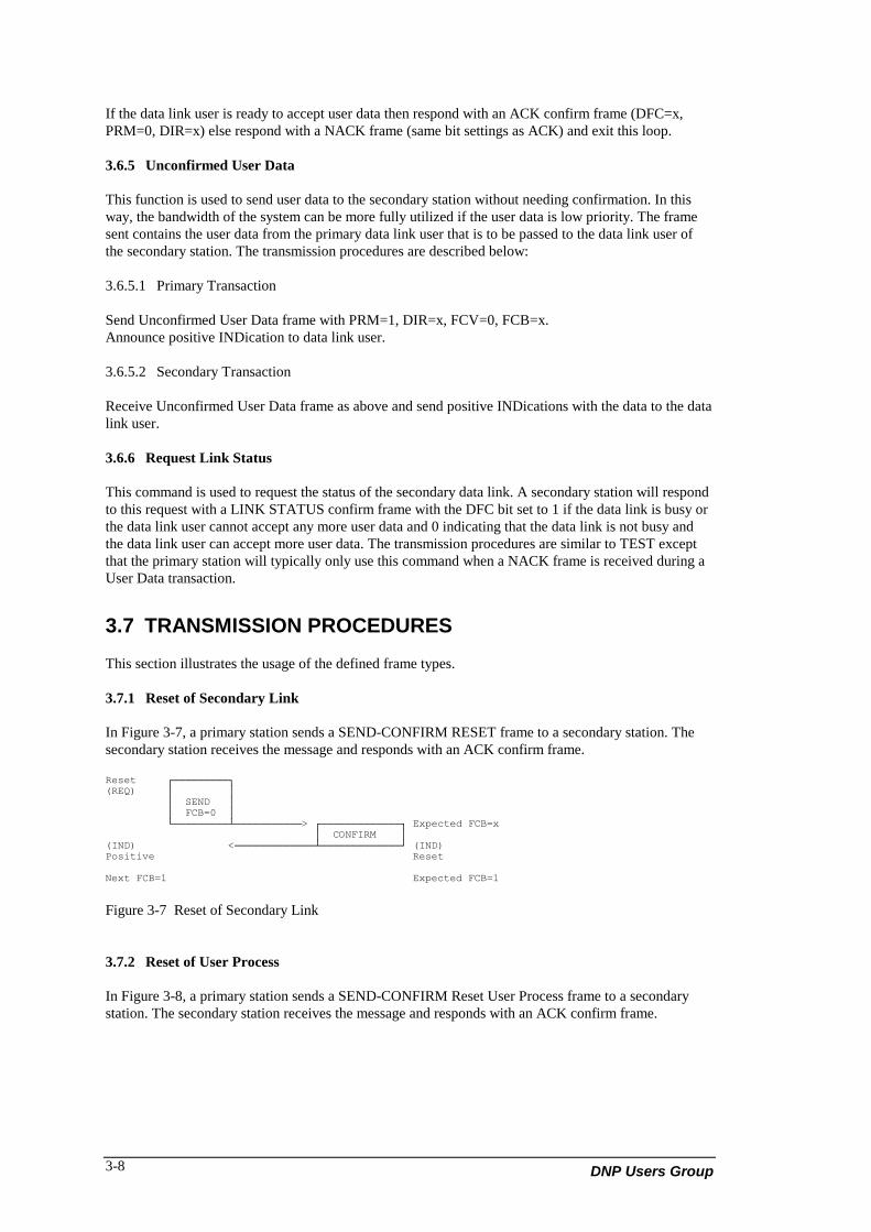
3.7.1 Reset of Secondary Link
In Figure 3-7, a primary station sends a SEND-CONFIRM RESET frame to a secondary station. Thesecondary station receives the message and responds with an ACK confirm frame.
Reset ┌─────────┐(REQ) │ │ │ SEND │ │ FCB=0 │ └─────────┴───────────> ┌─────────────┐ Expected FCB=x │ CONFIRM │(IND) <─────────────┴─────────────┘ (IND)Positive Reset
Next FCB=1 Expected FCB=1
Figure 3-7 Reset of Secondary Link
3.7.2 Reset of User Process
In Figure 3-8, a primary station sends a SEND-CONFIRM Reset User Process frame to a secondarystation. The secondary station receives the message and responds with an ACK confirm frame.

DNP V3.00 Data Link Layer (Version 0.02) 3-9
Reset User ┌─────────┐(REQ) │ │ │ SEND │ │ │ └─────────┴───────────> ┌─────────────┐ │ CONFIRM │(IND) <─────────────┴─────────────┘ (IND)Positive Reset User
Figure 3-8 Reset of User Process
3.7.3 Send/Confirm User Data
In Figure 3-9, the designated master station acting as a primary station sends a SEND-CONFIRM frameto a non-master station acting as a secondary station. This is the first frame with FCV valid after thesecondary link was reset (above) so FCB = 1 in the SEND frame. The secondary station expects FCB tobe 1 since this is the first frame (with FCV valid) after the link was reset (above) and sends aCONFIRM frame. The master station upon receiving the CONFIRM assumes the message wascorrectly received and INDicates success to the master station data link user.
STATION A STATION B
┌───────────┐(REQ) │ │ Expected FCB=1 │ SEND │ │ FCB=1 │ └───────────┴───────────> ┌─────────────┐ │ CONFIRM │ │ │ <─────────────┴─────────────┘(IND) (IND)Positive Data
Figure 3-9 SEND From Station A/CONFIRM From Station B
In Figure 3-10, a non-master station acting as a primary station sends a SEND-CONFIRM frame to adesignated master station acting as a secondary station. Since this is the second frame after thesecondary link has been reset the FCB = 0 in the SEND frame. The secondary expects FCB to be 0since this is the second frame received after the link was reset. A CONFIRM frame is sent in response.The non-master station upon receiving the CONFIRM INDicates success to the non-master station datalink user.
┌──────────┐ │ │ │ SEND │(REQ)Expected FCB=0 │ FCB=0 │ ┌─────────────┐<────────────┴──────────┘ │ CONFIRM │ │ │ └─────────────┴───────────> (IND) Positive(IND) User Data
Figure 3-10 SEND From Station B/CONFIRM From Station A

DNP Users Group3-10
In Figure 3-11, a designated master station sends 3 consecutive frames to the same non-master station.
(REQ 1) ┌─────────┐ │ SEND │ │ FCB=1 │ └─────────┴───────────> ┌───────────┐ Expected FCB=1 │ CONFIRM │ │ │(IND) Positive <────────────┴───────────┘ (IND) User Data(REQ 2) ┌─────────┐ │ SEND │ │ FCB=0 │ Expected FCB=0 └─────────┴─────────────> ┌───────────┐ │ CONFIRM │ │ │(IND) Positive <────────────┴───────────┘ (IND) User Data(REQ 3) ┌─────────┐ │ SEND │ │ FCB=1 │ Expected FCB=1 └─────────┴─────────────> ┌───────────┐ │ CONFIRM │ │ │(IND) Positive <────────────┴───────────┘ (IND) User Data
Figure 3-11 SEND Multiple Frames From Station A/CONFIRM From Station B
In Figure 3-12, the designated master acting as primary sends a one frame message to the secondarynon-master. This example illustrates what happens when the CONFIRM from the secondary station islost.
┌─────────┐(REQ) │ │ │ SEND │ Expected FCB=1 │ FCB=1 │ t DAB ─┬─ └─────────┴───────────> ┌───────────┐ │ t DBA │ CONFIRM │ │ │ │ │ garbled ──────────────┴───────────┘ (IND) User Data │ or not receivedretry delay > t DAB + t DBA + t CONFIRM duration + t SEND message processing time at station B │ ─┴─ ┌─────────┐ │ │(same data)│ SEND │ Expected FCB = 0 │ FCB=1 │ └─────────┴───────────> ┌───────────┐ send data is ignored, unexpected FCB │ │ but another confirm is sent │ CONFIRM │ │ │ <────────────┴───────────┘(IND) Positive
Figure 3-12 Frame Count Bit Operation
In Figure 3-13, the designated master acting as primary sends a two frame message to the secondarynon-master. This example illustrates what happens when the SEND frame from the primary station islost.
┌─────────┐(REQ) │ │ │ SEND │ Expected FCB = 0 │ FCB=0 │ └─────────┴───────────> ┌───────────┐ │ CONFIRM │ tBA │ │(IND) Positive┌─────────┐<────────────┴───────────┘ (IND) User Data │ SEND │ │ FCB=1 │ tAB └─────────┴──> (lost or garbled)
retry delay > tBA + tAB + CONFIRM time + CONFIRM processing time at Station B
┌─────────┐ │ SEND │ │ FCB=1 │ Expected FCB=1 └─────────┴───────────> ┌───────────┐ │ CONFIRM │ │ │(IND) Positive ───────── <────────────┴───────────┘ (IND) User Data
Figure 3-13 Frame Count Bit Operation

DNP V3.00 Data Link Layer (Version 0.02) 3-11
NOTE: Both a master station and non-master station acting as primary stations can re-try SENDframes.
3.7.4 Send/No Reply Expected
In Figure 3-14, the master or non-master primary station sends 3 frames to the secondary master or non-master. Upon successfully transmitting the SEND frame, the primary station INDicates success to thedata link user. The secondary station, upon reception of a valid frame INDicates data availability to thedata link user.
┌───────────┐(REQ) │ SEND │ │ NO REPLY │ │ │ ─┬─ └───────────┴───────────> (IND) Positive with user data │ delay before next frame = t SEND message processing at station B │ ─┴─ ┌───────────┐(REQ 2) │ SEND │ │ NO REPLY │ │ │ └───────────┴───────────> (IND) Positive with user data ─┬─ │ delay │ ─┴─ ┌───────────┐(REQ 3) │ SEND │ │ NO REPLY │ │ │ └───────────┴───────────> (IND) Positive with user data
Figure 3-14 SEND-NO-REPLY Expected From Station A
3.7.5 Send/NACK
In Figure 3-15, a non-master primary station sends a frame to the master secondary. Upon reception ofthe first CONFIRM, the primary INDicates success to the data link user. The primary sends a secondframe to the secondary. The secondary master decides that it cannot accept any frames at this time andsends a NACK frame back. The primary, after receiving this NACK, will fail the transaction and send anegative INDication to the data link user.
┌─────────┐ (REQ 1) │ SEND │Expected FCB=1 │ FCB=1 │ ┌───────────┐<────────────┴─────────┘ │ CONFIRM │ │ │(IND) Positive └───────────┴───────────> (IND) Positive ┌─────────┐ (REQ 2) │ SEND │ │ FCB=0 │ ┌───────────┐─────────────┴─────────┘ │ NACK │ └───────────┴───────────> (IND) Negative(IND) Negative
Figure 3-15 SEND From Station B/NACK From Station A
3.7.6 Request/Respond
In Figure 3-16, a primary station SENDs consecutive frames to a secondary station. When thesecondary station cannot receive any more frames, the CONFIRM message contains the DFC bit set.The primary station will, upon reception of the CONFIRM, stop SENDing data frames to the secondarystation but will instead periodically REQUEST the status of the secondary by sending a REQUEST-RESPOND frame. The secondary will RESPOND to the REQUEST frame with the current state of theDFC. If the secondary is ready to receive more data, the DFC returned will be 0 otherwise the DFCreturned will be 1. When the primary station recognizes DFC = 0 in the RESPOND frame, thetransmission of SEND frames will continue.

DNP Users Group3-12
┌───────────┐(REQ 1) │ │ │ SEND │ │ FCB=0 │ └───────────┴───────────> ┌───────────┐ │ CONFIRM │(IND) Positive │ DFC=0 │Receipt of CONFIRM frame ┌───────────┐<────────────┴───────────┘ (IND) User Datawith DFC = 0 is the │ SEND │condition for │ │transmission of the next │ FCB=1 │SEND user data frame. └───────────┴───────────> ┌───────────┐ │ CONFIRM │ │ DFC=1 │(IND) Positive ┌───────────┐<────────────┴───────────┘ (IND) User Data │ REQUEST │ but buffers full now │ RESPOND │ │ │ └───────────┴───────────> ┌───────────┐ │ CONFIRM │ │ DFC=1 │ ┌───────────┐<────────────┴───────────┘ │ REQUEST │ │ RESPOND │ │ │ └───────────┴───────────> ┌───────────┐(REQ 3) │ CONFIRM │ │ DFC=0 │Receipt of CONFIRM frame ┌───────────┐─────────────┴───────────┘with DFC = 0 is the │ SEND │condition for │ │transmission of the next │ FCB=0 │ (IND)SEND user data frame. └───────────┴───────────> ┌───────────┐ │ CONFIRM │ │ DFC=0 │ <────────────┴───────────┘ (IND) User Data
Figure 3-16 REQUEST/RESPOND Frame and DFC Bit Usage

DNP V3.00 Data Link Layer (Version 0.02) 4-1
4. DATA LINK SERVICES ANDRESPONSIBILITIES
4.1 DATA LINK FUNCTIONS
This section describes the services offered by the data link and its functions. The communicationrequirements of the network layer and the pseudo-transport layer are satisfied by the data link layerservice primitives.
The data link is responsible for performing the following functions:• Performing message retries• Synchronizing and handling of the FCB bit in the control word• Setting and clearing the DFC bit based on buffer availability• Automatically establishing a connection based on the destination parameter in a dial up environment
when a directed service is requested by the user• Disconnection in a dial-up environment• Packing user data into the defined frame format and transmitting the data to the physical layer• Unpacking the frames that are received from the physical layer into user data• Controlling all aspects of the physical layer• Performing collision avoidance/detection procedures to ensure the reliable transfer of data across
the physical link• Responding to all valid frames (function codes) received from the physical layer.
The data link is responsible for providing the following services:• Exchange of SDUs between peer DNP data links• Error notification to data link user• Sequencing of SDUs• Prioritized SDU delivery• Quality SDU delivery.
SDUs will only be exchanged between peer DNP data links.
Priority delivery can be EXPEDITED or NORMAL to indicate a high or low priority request.
Quality delivery can be SEND-NO-REPLY or SEND-CONFIRM to indicate whether or not messageacknowledgment is required.
Error notification will be given to the data link user when a response to a request has not been received.
4.2 INTERFACE DESCRIPTION
The data link service primitives are illustrated in pseudo code to illustrate the requirements andbehavior in a real implementation and are not intended as an exact interface definition.
Data link request (REQ) services can be used at any time after the data link has been initialized andconfigured by the system.

DNP Users Group4-2
confirm = request_data_link_service(SERVICE,TIME_SERVICE,destination,source,send_data_buffer,send_count,retry_flag,time_of_transmission
)
Input:SERVICE Service to performTIME_SERVICEGuaranteed time service to performsource Source address to use in sent messagedestination Destination address to use in sent messagesend_data_buffer Data to send in messagesend_count Number of octets in messageretry_flag Instructs data link layer to retry unacknowledged frames or nottime_of_transmission Time that first bit of first octet of message is to be sent
Output:time_of_transmission Time that first bit of first octet of message was sent
Confirm = 0 Requested service was successful1 Requested service has failed2 Requested SEND data service was terminated by the current primary station.
(reception of a NACK frame from the secondary station)3 Service code is not implemented4 Requested service cannot proceed at this time because the data link is busy
either with a previous requested transaction, current unrequested transactionor waiting for physical layer availability
Service = 0 Send a message specified in parameters using SEND-CONFIRM frames.Fails if the data link is busy
1 Send a message specified in parameters using SEND-NO- REPLY frames.Fails if the data link is busy
2 Expedited send a message specified in parameters using SEND-CONFIRMframes. May necessitate cancelling the current secondary transaction if ahalf-duplex system is used (i.e. forces the data link to send a NACK frameinstead of a CONFIRM frame in the next secondary transaction). This actiononly takes place if the primary station is using SEND-CONFIRM frames.
3 Expedited send a message specified in parameters using SEND-NO-REPLYexpected frames. In a half-duplex system, this may mean cancelling thecurrent secondary transaction (as above).
4 Return link status. Return successful if the data link is not busy.
Time_service 0 Send message at time specified in time_of_transmission. This service shouldhave the highest priority.
1 Send message at any time with priority specified.

DNP V3.00 Data Link Layer (Version 0.02) 4-3
Data link indications (IND) can be requested at any time by the service user but should be checked asoften as possible in order to obtain received data.
indications = request_data_link_indications(source_address,destination_address,received_data_buffer,received_data_count,time_of_reception)
Output:source_address Source address of received messagedestination_address Destination address of received addressreceived_data_buffer Received messagereceived_data_count Number of octets in messagetime_of_reception Time at which first bit of first octet of message was received
Indications = 0 No indications to report1 Data link has received a valid message that has been placed in
received_data_buffer and the number of octets received has been placed inreceived_data_count. The source address of the received message has beenplaced in source_address. If the data link is configured as a master stationthen the time that the first bit of the first octet of the message was receivedhas been placed in time_of_reception. If the data link is configured as anoutstation then the time_of_reception will still be returned but the serviceuser has to be aware of the possibility of inaccurate times received before theoutstation has been time-synchronized.
2 Data link has detected a transaction failure.

DNP V3.00 Data Link Layer (Version 0.02) 5-1
5. PHYSICAL LAYER INTERFACE
This section describes the DNP Version 3 Data Link to physical layer interface. The interface describesthe necessary services that ANY physical layer must provide in order to accommodate the DNP V3.00Data Link.
5.1 PHYSICAL LAYER DESCRIPTION
The physical layer that is recommended for the data link is a bit-serial oriented asynchronous physicallayer supporting 8 bit data, 1 start bit, 1 stop bit, no parity and RS-232C voltage levels and controlsignals. The CCITT V.24 standard describes the DTE (Data Terminal Equipment) which is used forcommunication with a DCE (Data Communication Equipment) and is usually a frequency-switchedmodem (FSK). This type of circuit connection to a PSN (Public Switching Network) or to privateleased lines can be used. In each case, the appropriate modem must be used and must conform(minimally) to the V.24 standard DCE definition.
The physical layer must provide 5 basic services: Send, Receive, Connect, Disconnect, and Status. TheSend service converts data octets into bit-serial data for transmission between the DTE and DCE. Itmust provide the proper signal control in order to communicate with the given DCE. The Receiveservice must be able to accept data from the DCE and therefore provide the correct signaling to theDCE in order to receive data and not noise. The Connect and Disconnect services provide connectionand disconnection from the PSN (if applicable). The Status service must be able to return the state ofthe physical medium. As a minimum, the service must indicate whether or not the medium is busy.
The physical link service primitives are illustrated in pseudo code to illustrate the requirements andbehavior in a real implementation and are not intended as an exact interface definition.
Physical layer requests can be sent at any time after the physical layer has been started and configuredwith all relevant parameters.
confirm = request ( SERVICE,data_buffer,data_count,modem_string,time_of_transmission)
Input:data_buffer Data to senddata_count Number of octets to sendmodem_string Command string for DCE
Output:time_of_transmission Time that first bit of first octet of message was transmitted
Confirm = 0 Requested service was successful1 Requested service has failed2 Service code is not implemented3 Requested service cannot proceed at this time because the physical link is
busy either with a previous requested transaction, current unrequestedtransaction or waiting for DCE availability

DNP Users Group5-2
Service = 0 Send a message specified in data_buffer of size specified in data_count1 Initialize DCE using string specified in modem_string2 Connect to PSN using string specified in modem_string3 Disconnect from PSN4 Request physical link status, returns 0 if busy and 1 if not busy
Physical layer indications (IND) can be requested at any time by the service user but should be checkedas often as possible in order to obtain received data.
indications = indicate(received_data_buffer,received_data_count,time_of_reception)
Output:received_data_buffer Received messagereceived_data_count Number of octets in messagetime_of_reception Time at which first bit of first octet of message was received
Indications = 0 No indications to report.1 Physical layer has received a message that has been placed in
received_data_buffer and the number of octets received has beenplaced in received_data_count.
2 DCE has connected to PSN (incoming call).3 DCE has disconnected from PSN (hang up).4 Physical layer has detected problems with the link or DCE that
makes communication inadvisable or impossible until some latertime. Re-initialization of the DCE may be required.

DNP V3.00 Data Link Layer (Version 0.02) 6-1
6. PHYSICAL LAYERCHARACTERISTICS
6.1 LINE CONFIGURATIONS
Regardless of the physical layer used, there are two physical topologies used to construct a SCADAcommunications network. These are direct and serial bus topologies.
The direct topology has two physical nodes with each physical node connected directly to the other.This is often referred to as point-to-point and can be a direct physical cable from point-to-point, a twonode radio or modem network or a dial-up connection through a PSN (Public Switched Network).
The serial bus topology has more than two physical nodes with each node connected to the samechannel or communication line as every other node in the serial bus network. This is often referred to asa multi-drop configuration and is commonly made up of many Bell 202 modems with theiroutputs/input tied together. In this configuration, there is one node which is deemed to be in control ofthe physical network. This is often the SCADA master. This node transmits to multiple-nodes andreceives from multiple nodes. All other nodes in the bus receive from the master node and transmit tothe master node.
The DNP data link supports multiple-master, multiple-slave and peer-to-peer communications.
In peer-to-peer communications, all devices act as slave data links and collision avoidance should beturned on as no one device has a higher priority and all can transmit spontaneously.
In a multiple-master configuration, the master devices are higher priority than the slave devices.However, priority has to be assigned amongst the masters.
6.2 MODES OF TRANSMISSION
The physical layer supported by DNP must transmit/receive data in serial mode. Generally, the data unittransferred will be 8 bits in length. The transmission can be asynchronous, synchronous or isochronousallowing for higher throughput with a synchronous modem. The actual mechanism used has no affect onthe operation of the data link.
6.3 LOCAL LOOP
The termination of the data communications circuit at the communication node (i.e. NOT at themodem) can be accomplished using a two-wire or four-wire circuit (i.e. TX/RX pair or independent TXand RX pairs).
The DNP data link can use half-duplex procedures with a 2-wire circuit and full-duplex or half-duplexprocedures with a 4-wire circuit.
The DNP data link can support both full-duplex and half-duplex procedures at the local loop. Bothcases, however will be handled quite differently.


DNP V3.00 Data Link Layer (Version 0.02) 7-1
7. PHYSICAL LAYER PROCEDURES
7.1 GENERAL CONSIDERATIONS
The purpose of the data link to physical layer interface is to allow the data link to send or receive amessage to or from another data link. To accomplish this, the data link must be able to control when thetransmission of data takes place, detect the presence of data on the physical communication circuit anduse control line signaling for control of the physical circuit. In addition, the master station (or highestpriority device) needs to be able to take control of the communication circuit and block other stationsfrom transmitting.
In a direct connection type topology, the primary station (initiating station) can only communicate withone station. If this circuit is four-wire then full-duplex procedures will be used and there will be nochance of message collisions on the circuit. However, if the circuit is two-wire then half-duplexprocedures will be used. In this case, a collision can occur if both stations attempt to transmit data at thesame time. A direct connect to a dial-up PSN is typically 2-wire but the circuit from the station to themodem is a 4-wire full-duplex circuit and should be used in a full-duplex fashion. The dial-up modemmust use CTS to hold off the transmitter after RTS is asserted.
In a multi-drop topology, the designated master station can act as a primary station to many secondarystations. In this case there is a chance of collision in a two-wire or four wire circuit.
In a two-wire circuit, the designated master station messages can collide with any other stationsmessage and the slave station messages can collide with each other at any time.
In a four wire circuit, the master station messages cannot collide with the slave station messages but theslave station messages can collide with each other.
7.2 HALF-DUPLEX PROCEDURES
When half duplex procedures are used in a two-wire system, there are several ways to avoid or recoverfrom a collision on the communication circuit. Regardless of the physical layer used, all physical layersshould be able to return a data carrier detection indication (DCD) which indicates if there is traffic onthe circuit. In a two-wire system, the indication appears when the master or slave is transmitting on thecircuit. When this indication is present, a station is transmitting on the circuit. During this time, no otherstation should attempt to transmit on the circuit. When the indication disappears, the circuit is free forsomeone to use. The question now is, which station is allowed to transmit on the circuit.
In the point-to-point configuration, either the master or slave station could transmit. In the multi-dropconfiguration, either the master or any of many slave stations could transmit. The DNP data linkprotocol does not assign priority to either the master or slave message but it is generally accepted inSCADA that the master should have control of the communication circuit and therefore should transmitthe message (if one is to be sent). Any slave station, if allowed to transmit at this point, could possiblycause a collision so the slave station must wait some time after detecting the loss of a data carrier beforeattempting to send. Before sending, the indication is checked again and if the circuit is still idle then thetransmission can take place. If the circuit is busy then the station must wait again until the indicationdisappears and perform the procedure again. The insertion of the time delay after the loss of data carrier

DNP Users Group7-2
allows the master to take control of the circuit (if needed at that time) and shuts out the other station(because the carrier indication is caused by the masters transmission).
7.2.1 Point-to-Point
In a point-to-point configuration this time delay only needs to be as long as the time needed for themaster to detect the loss of data carrier and begin the transmission of the message (plus any propagationdelays in the system) (Master_min time).
7.2.2 Multi-Point
In a multi-drop configuration, this time delay needs to be different for each slave station. Onepossibility is to configure each slave station to wait a steadily increasing amount of time (no duplicatetimes and all greater than Master_Min time) hence assigning priorities to the stations. In this way,stations which are important in the system can be given higher priority and collisions will rarely happen(only if device timing is bad or the system is poorly configured). However, if the high priority slavestations have nothing to transmit, then there is a lot of time (and hence bandwidth) wasted.
Another scheme is to configure each slave station to wait a random time between Master_Min and Max.This Max is a function of the number of slave stations in the system. In this way, each station can beconfigured in the same way and the average time wasted is about (Max - Master_Min) / 2. However, acollision is still possible if two stations decide to wait for the same amount of time. The smaller theMax value the greater the chance of this happening.
7.3 FULL-DUPLEX PROCEDURES
When full-duplex procedures are used in a four-wire direct connection circuit, there is no chance ofcollision because there exists two independent channels for both the reception and transmission ofmessages. In this case, both the master and slave stations can transmit data at any time when needed.The master still has control of the circuit because there is only one station to talk to, hence no need toblock out other stations.
When full-duplex procedures are used in a four-wire multi-drop system the problem of collisionavoidance increases in complexity. The reason for this lies in the fact that a physical communicationcircuit that has two independent channels usually can only detect traffic in the receive direction. In atwo-wire system, any traffic in the receive or transmit direction can be detected because they are bothon the same circuit but in a four-wire system the transmitted and received messages travel on differentcircuits.
7.3.1 Point-to-Point
In a point-to-point, full-duplex system both master and slave can transmit at the same time withoutcollision so there is no need for collision detection/avoidance or access mechanisms in this case.
7.3.2 Multi-Point
In a full-duplex, multi-drop system, the master station can transmit messages at any time withoutcollision but may not receive the data link confirmation immediately because another station (acting asa primary station) may have taken control of the master's receive circuit before the secondary station ora collision occurred.
The slave station's messages will collide at random because there is no way for the station to know ifanother station has control of the master's receive circuit. The solution is to make use of a controlcircuit (RTS in the case of RS-232) to signal the slave stations when another slave station has takencontrol of the master's receive circuit. This signal must be an input to the slave stations which indicatesa request to take control of the master's receive circuit.
One simple solution is to allow slave messages to collide. In this way, the master can still send out highpriority messages but there may be a collision which will cause a secondary station to time-out.

DNP V3.00 Data Link Layer (Version 0.02) 7-3
7.3.3 Dial-Up Modem
A dial-up modem uses a four-wire full-duplex circuit that typically requires several control signals(other than DCD) in order to operate. The dial-up circuit is a point-to-point circuit. However, themeaning of the data carrier signal is quite different than with a direct circuit. The data carrier (DCD)indicates that the modem is electrically connected to another modem across the PSN. It does notnecessarily mean that data is being transmitted on the circuit. The CTS (Clear To Send) line indicates tothe data link when it is safe to transmit. The DNP data link will assert the RTS (Request To Send) linebefore transmitting each frame and wait for the CTS line to go high before transmitting the data. TheRTS line will then be de-asserted. If the DCD line goes low, the data link will assume that a connectionhas been lost and attempt to re-dial if needed.

DNP Users Group7-4
DNP V3.00 Data Link Layer (Version 0.02) 1
LIST OF ABBREVIATIONS ANDACRONYMS
CRC cyclic redundancy check
DFC data flow controlDIR direction of physical transmissionDNP Distributed Network Protocol
EPA enhanced protocol architecture
FCB frame control bitFCV frame count valid
IEC International Electrotechnical CommissionIED intelligent electronic deviceISO International Organization for Standardization
LPDU link protocol data unitLSDU link service data unit
octet 8-bit data object (byte)OSI Open System Interconnection
PRM primary
DNP Users Group
DNP PRODUCT DOCUMENTATION
DNP V3.00TRANSPORT FUNCTIONS
Document Version: 0.01Internal File: P009-0PD.TF
Associated Software Release: DNP V3.00

NOTICE OF RIGHTS - DNP USERS GROUP
The contents of this manual are the property of the DNP UsersGroup. Revisions or additions to the definition and functionality ofthe Distributed Network Protocol cannot be made without expresswritten agreement from the DNP Users Group or its duly authorizedparty. In addition, no part of this document may be altered orrevised or added to in any form or by any means, except as permittedby written agreement with the DNP Users Group or a Party dulyauthorized by the DNP Users Group.
As a Party, duly authorized by the DNP Users Group, HarrisCorporation has made every reasonable attempt to ensure thecompleteness and accuracy of this document, however, theinformation contained in this manual is subject to change withoutnotice, and does not represent a commitment on the part of HarrisCorporation or the DNP Users Group. An update program for DNPdocuments is provided upon request by Harris Corporation onbehalf of the DNP Users Group.
TRADEMARK NOTICES
Brand and product names mentioned in this document aretrademarks or registered trademarks of their respective companies.

DNP V3.00 Transport Functions (Version 0.01) i
TABLE OF CONTENTS
ABOUT THIS DOCUMENT iiiPURPOSE OF THIS SPECIFICATION iiiWHO SHOULD USE THIS SPECIFICATION iiiHELP AND ADDITIONAL DOCUMENTATION iiiHOW THIS SPECIFICATION IS ORGANIZED ivCONVENTIONS USED IN THIS SPECIFICATION iv
1. OVERVIEW 1-1
2. TRANSPORT FUNCTIONS 2-12.1 TRANSPORT HEADER 2-12.2 TRANSPORT HEADER FIELD DEFINITIONS 2-22.3 FRAME ASSEMBLING 2-32.4 TRANSMISSION OF MESSAGES 2-3
3. TRANSPORT SERVICES AND RESPONSIBILITIES 3-13.1 TRANSPORT FUNCTIONS 3-13.2 INTERFACE DESCRIPTION 3-2
LIST OF ABBREVIATIONS AND ACRONYMS

DNP Users Groupii
TABLE OF FIGURES
FIGURE 2-1 TRANSPORT LAYER MESSAGE LAYOUT 2-2FIGURE 2-2 TH BIT DEFINITIONS 2-2FIGURE 2-3 ASSEMBLING OF DATA FROM THREE DATA FRAMES 2-3FIGURE 2-4 TRANSMISSION OF A SINGLE FRAME MESSAGE 2-4FIGURE 2-5 FRAGMENTING OF A MULTI-FRAME APPLICATION MESSAGE 2-4
DNP V3.00 Transport Functions (Version 0.01) iii
ABOUT THIS DOCUMENT
PURPOSE OF THIS SPECIFICATION
This document specifies the Distributed Network Protocol (DNP) V3.00 TransportFunctions, transmission procedures and Transport Protocol Data Unit.
WHO SHOULD USE THIS SPECIFICATION
This specification is intended for communication engineers and programmersinterested in knowing the function and message format of the DNP V3.00 TransportFunctions. This includes programmers implementing and designing DNP V3.00Transport Functions software/hardware and quality assurance personnel testing andverifying implementations of the DNP V3.00 Transport Functions. Applicationprogrammers may find this specification useful in determining how to interface withand make use of the DNP V3.00 Transport Functions. Familiarity with the ISO-OSI 7-layer model, IEC 3-layer EPA and IEC TC-57 standards is helpful.
HELP AND ADDITIONAL DOCUMENTATION
The following documentation may be helpful.• IEC 870-5-1 and IEC 870-5-2 standards (or drafts), Technical Committee No. 57
for data transmission in telecontrol systems• DNP V3.00 Data Object Library (P009-0BL)• DNP V3.00 Application Layer (P009-0PD.APP)• DNP V3.00 Data Link Layer (P009-0PD.DL).

DNP Users Groupiv
HOW THIS SPECIFICATION IS ORGANIZED
1. OVERVIEWA general overview of the transport functions.
2. TRANSPORT FUNCTIONSA detailed description of the packet formats and transmission procedures.
3. TRANSPORT SERVICES AND RESPONSIBILITIESServices provided by an interface to the transport functions.
LIST OF ABBREVIATIONS AND ACRONYMS
CONVENTIONS USED IN THIS SPECIFICATION
In this document, the octet is a term used to refer to an eight bit-data object and issynonymous with the term byte. The low order bit of an octet is referred to as bit 0 andthe high order bit as bit 7.
Irregular capitalization is used in referencing technical terms which have an associatedverb or noun. For example, data link indications commonly referred to as IND, canalso be described using the word INDication.

DNP V3.00 Transport Functions (Version 0.01) 1-1
1. OVERVIEW
This document defines the Distributed Network Protocol (DNP) V3.00 TransportFunctions, Transport Protocol Data Unit (TPDU), as well as transport services andtransmission procedures. Master stations, submaster stations and outstations orintelligent electronic devices (IEDs) can use these transport functions to passmessages between primary (originating) stations and secondary (receiving) stations. Inthis protocol, master stations, submaster stations and outstations are both originators(primary stations) and receivers (secondary stations).
The ISO (International Organization for Standardization) OSI (Open SystemInterconnection) model supported by this protocol specifies physical, data link andapplication layers only. This is termed the Enhanced Protocol Architecture (EPA).However, to support advanced RTU functions and messages larger than the maximumframe length as defined by the IEC (International Electrotechnical Committee)document 870-5-1, the DNP V3.00 Data Link is intended to be used with this pseudo-transport layer which implements message assembly and disassembly.
This pseudo-transport layer is actually a super-data link transport protocol which isnormally found as part of some OSI data links. However, because the IEC data link(DNP V3.00 Data Link Layer) does not support these functions in the data link, it isnecessary to move them out of the data link in order to maintain compliance.


DNP V3.00 Transport Functions (Version 0.01) 2-1
2. TRANSPORT FUNCTIONS
This section describes the Transport layer functions which act as a pseudo-transportlayer to the DNP data link layer. The pseudo-transport layer function is specific onlyfor those messages that are larger than one Link Protocol Data Unit (LPDU) betweenprimary and secondary stations. This pseudo-transport layer acts as the DNP data linkuser in a protocol stack consisting of only the DNP Data Link and DNP ApplicationLayer. This functionality allows the pseudo-transport layer to disassemble oneTransport Service Data Unit (TSDU) into multiple (more than one) Transport ProtocolData Units (TPDUs), or frames, and assemble multiple (more than one) TPDUs intoone TSDU.
This process works as follows:The pseudo-transport layer takes one TSDU (user data) and breaks it into severalsequenced TPDUs (each with Transport Protocol Control Information (TPCI)). EachTPDU is sent to the data link layer as Link Service Data Unit (LSDU) fortransmission.It also works in the reverse fashion. The pseudo-transport layer receives multipleTPDUs from the data link layer and assembles them into one TSDU.LSDUs are user data fragments which are small enough to fit into the defined FT3frame format. When a primary station transmits a message to a secondary station, thetransport functions break the message into LSDUs. These functions add a Transportlayer Header (TH) octet at the beginning of the user data fragments that contain theinformation for the secondary station to reconstruct the complete message. Allpseudo-transport layer messages have a TH.
The secondary station checks the TH octet on reception of each LSDU for the correctsequence and builds a TSDU message for higher layers.
The TH contains information that can identify the first frame, last frame and giveevery frame a six-bit sequence number. This information is required to reconstruct amessage and also to guard against higher layers from receiving misdirected orincomplete messages.
2.1 TRANSPORT HEADER
After the data link receives a complete frame, the data is presented to the transportfunctions in a format illustrated below. The TH field is stripped out before the frameis combined with other frames belonging to the same message. Figure 2-1 shows thestructure of a TPDU.

DNP Users Group2-2
----------------- | | | | TH | USER DATA | | | | -----------------
Figure 2-1 Transport Layer Message Layout
TH Transport control octet. One octet in length.USER DATA 1 to 249 octets in length.
When an application requests the transmission of a long message, the message isbroken into fragments small enough to fit in a single DNP V3.00 Data Link frame.The maximum size of a fragment is 249 octets of user data. The TH is added to thehead of the fragment and the maximum number of octets to be framed becomes 250octets.
Maximum data link data count + 255 octetsData link header data count - 5 octetsTransport header - 1 octetApplication user data = 249 octets
2.2 TRANSPORT HEADER FIELD DEFINITIONS
----------------------------------------------- | | | | | | | | | | FIN | FIR | | | SEQUENCE | | | | | | | | | | | | -----------------------------------------------BIT 7 6 5 4 3 2 1 0
Figure 2-2 TH Bit Definitions
FIN The final bit indicates that this frame of user data is the last frame of asequence which compromises a complete user message.FIN = 0 More frames follow.
1 Final frame of a sequence.
FIR The first bit indicates that the frame is the first in a sequence offrame(s) which comprise a complete message. When a secondarystation receives a frame with the FIR bit set, all previously receivedunterminated frame sequences are discarded. The first frame of asequence may have any sequence from 0 to 63.If a frame is received without the FIR bit set and no message sequenceis currently in progress, then the frame is ignored.If a complete user message is only one frame in length, both the FIRand FIN bits are set.FIR = 1 First frame of a sequence.
0 Not the first frame of a sequence.
SEQUENCE The sequence number of the frame is used to check that each frame isbeing received in sequence. It guards against missing or duplicatedframes. All user messages start off with a sequence specified in the

DNP V3.00 Transport Functions (Version 0.01) 2-3
first frame which has the FIR bit set (each message may start with anysequence number between 0 and 63). After sequence number 63 thenext sequence number will be 0.The sequence number increments for each frame sent to or receivedfrom the same address belonging to the same message and resets at thebeginning of a new message. The sequence number does not have toincrement across message boundaries, i.e. any sequence number isvalid when the FIR bit is set.
2.3 FRAME ASSEMBLING
Figure 2-3 illustrates the assembling of a three-frame message. The first frame of themessage identified by having the FIR bit set in the TH field. The last frame isidentified by having the FIN bit set in the TH field.
USER DATA FRAMES TRANSPORT DATA BUFFER --------------| SOURCE = n | -------------- --------------| FIR = 1 || FIN = 0 || SEQUENCE = 3| Note sequence starts with the value in the frame that has the FIR bit = 1| USER DATA 0 | -------------- -----------> ------------- | USER DATA 0 | ------------- --------------| SOURCE = n | -------------- --------------| FIR = 0 || FIN = 0 || SEQUENCE = 4|| USER DATA 1 | -------------- -----------> ------------- | USER DATA 1 | ------------- | USER DATA 0 | ------------- --------------| SOURCE = n |-----------------------------------> -------------- SOURCE ADDRESS passed to application --------------| FIR = 0 || FIN = 1 | FIN indicates last frame| SEQUENCE = 5|| USER DATA 2 | -------------- -----------> ------------- | USER DATA 2 | FIN indicated this is the last frame of message ------------- | USER DATA 1 | ------------- | USER DATA 0 | complete message passed to application ------------- ----------->
Figure 2-3 Assembling of Data From Three Data Frames
2.4 TRANSMISSION OF MESSAGES
Figure 2-4 illustrates the transmission of a single frame message using the SEND -CONFIRM frame service. Figure 2-5 illustrates the transmission of a multi-framemessage using the SEND - CONFIRM frame service.

DNP Users Group2-4
FRAMES SENT FROM DATA LINK COMPLETE MESSAGE FROM APPLICATIONCONFIRM FRAMES RECEIVED --------------- | DESTINATION | parameter from application ---------------
--------------- | USER DATA | | | | 30 octets | --------------- -------------- | DESTINATION | parameter to data link -------------- -------------- | FIR = 1 | | FIN = 1 | 1 TH octet | SEQUENCE = 1 | | USER DATA 0 | send 30 user octets plus 1 TH = 31 octets SEND <----- -------------- CONFIRM -------> --------------------> SUCCESS to application layer
Figure 2-4 Transmission of a Single Frame Message
-------------- | DESTINATION | parameter from application --------------
-------------- | USER DATA | | | | 598 octets | -------------- -------------- | DESTINATION | parameter to data link -------------- -------------- | FIR = 1 | | FIN = 0 | 1 TH octet | SEQUENCE = 2 | | USER DATA 0 | send 249 octets (1 to 249 is the valid range for this count) SEND <------- -------------- CONFIRM --------> -------------- | DESTINATION | parameter to data link -------------- -------------- | FIR = 0 | | FIN = 0 | | SEQUENCE = 3 | | USER DATA 1 | send 249 octets SEND <------- -------------- CONFIRM --------> -------------- | DESTINATION | parameter to data link -------------- -------------- | FIR = 0 | | FIN = 1 | | SEQUENCE = 4 | | USER DATA 2 | send last 100 octets (249 + 249 + 100 = 598) SEND <------- -------------- CONFIRM --------> --------------------> SUCCESS to application layer
Figure 2-5 Fragmenting of a Multi-Frame Application Message

DNP V3.00 Transport Functions (Version 0.01) 3-1
3. TRANSPORT SERVICES ANDRESPONSIBILITIES
3.1 TRANSPORT FUNCTIONS
This section describes the services offered by the pseudo-transport layer and itsfunction. The communication requirements of the network layer and the applicationlayer are satisfied by the pseudo-transport layer service primitives.
The pseudo-transport layer is responsible for performing the following functions:• Packing user data into multiple frames (more than one) of the defined DNP V3.00
Data Link frame format and using the services of the DNP V3.00 Data Link fortransmitting the data
• Unpacking multiple frames that are received from the data link into user data• Controlling all aspects of the data link excluding data link configuration.
The pseudo-transport layer is responsible for providing the following services:• Exchange of SDUs between peer DNP V3.00 pseudo-transport layers• Error notification to transport user• Sequencing of SDUs• Prioritized SDU delivery• Quality SDU delivery.
SDUs will only be exchanged between peer DNP V3.00 pseudo-transport layers.
Error notification is given to the transport user when a response to a request has notbeen received.
Priority delivery can be set to EXPEDITED or NORMAL to indicate a high or lowpriority request.
Quality delivery can be set to SEND-NO-REPLY or SEND-CONFIRM to indicatewhether or not message acknowledgment is required.
DNP Users Group3-2
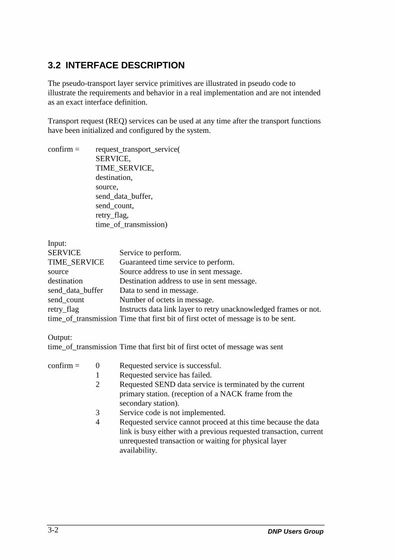
3.2 INTERFACE DESCRIPTION
The pseudo-transport layer service primitives are illustrated in pseudo code toillustrate the requirements and behavior in a real implementation and are not intendedas an exact interface definition.
Transport request (REQ) services can be used at any time after the transport functionshave been initialized and configured by the system.
confirm = request_transport_service(SERVICE,TIME_SERVICE,destination,source,send_data_buffer,send_count,retry_flag,time_of_transmission)
Input:SERVICE Service to perform.TIME_SERVICE Guaranteed time service to perform.source Source address to use in sent message.destination Destination address to use in sent message.send_data_buffer Data to send in message.send_count Number of octets in message.retry_flag Instructs data link layer to retry unacknowledged frames or not.time_of_transmission Time that first bit of first octet of message is to be sent.
Output:time_of_transmission Time that first bit of first octet of message was sent
confirm = 0 Requested service is successful.1 Requested service has failed.2 Requested SEND data service is terminated by the current
primary station. (reception of a NACK frame from thesecondary station).
3 Service code is not implemented.4 Requested service cannot proceed at this time because the data
link is busy either with a previous requested transaction, currentunrequested transaction or waiting for physical layeravailability.

DNP V3.00 Transport Functions (Version 0.01) 3-3
service = 0 Send a message specified in parameters using SEND-CONFIRM frames. Fails if the data link is busy.
1 Send a message specified in parameters using SEND-NO-REPLY frames. Fails if the data link is busy.
2 Expedited send a message specified in parameters using SEND-CONFIRM frames. May necessitate canceling the currentsecondary transaction if a half-duplex system is used.(i.e. forcesthe data link to send a NACK frame instead of a CONFIRMframe in the next secondary transaction). This action only takesplace if the primary station is using SEND-CONFIRM frames.
3 Expedited send a message specified in parameters using SEND-NO-REPLY expected frames. In a half-duplex system, this maymean canceling the current secondary transaction. (as above).
4 Return link status. Return successful if the data link is not busy.
time_service =0 Send message at time specified in time_of_transmission. Thisservice should have the highest priority.
1 Send message at any time with priority specified.
Data link indications (IND) can be requested at any time by the service user butshould be checked as often as possible in order to obtain received data.
indications = request_data_link_indications(source_address,destination_address,received_data_buffer,received_data_count,time_of_reception)
Output:source_address Source address of received message.destination_address Destination address of received address.received_data_buffer Received message.received_data_count Number of octets in message.time_of_reception Time at which first bit of first octet of message was received.

DNP Users Group3-4
Indications = 0 No indications to report.1 Data link has received a valid message that has been placed in
received_data_buffer and the number of octets received hasbeen placed in received_data_count. The source address of thereceived message has been placed in source_address. If the datalink is configured as a master station then the time that the firstbit of the first octet of the message was received has beenplaced in time_of_reception. If the data link is configured as anoutstation then the time_of_reception will still be returned butthe service user has to be aware of the possibility of inaccuratetimes received before the outstation has been time-synchronized.
2 Pseudo-transport layer has detected a transaction failure.

DNP V3.00 Transport Functions (Version 0.01) 1
LIST OF ABBREVIATIONS ANDACRONYMS
CRC cyclic redundancy check
DNP Distributed Network Protocol
EPA enhanced protocol architecture
IEC International Electrotechnical CommissionISO International Organization for Standardization
octet 8-bit data object (byte)OSI Open System Interconnection
RTU remote terminal unit

DNP Users Group
DNP PRODUCT DOCUMENTATION
DNP V3.00APPLICATION LAYER
Document Version: 0.03Internal File: P009-0PD.APP
Associated Software Release: DNP V3.00
NOTICE OF RIGHTS - DNP USERS GROUP
The contents of this manual are the property of the DNP UsersGroup. Revisions or additions to the definition and functionality ofthe Distributed Network Protocol cannot be made without expresswritten agreement from the DNP Users Group or its duly authorizedparty. In addition, no part of this document may be altered orrevised or added to in any form or by any means, except as permittedby written agreement with the DNP Users Group or a Party dulyauthorized by the DNP Users Group.
As a Party, duly authorized by the DNP Users Group, HarrisCorporation has made every reasonable attempt to ensure thecompleteness and accuracy of this document, however, theinformation contained in this manual is subject to change withoutnotice, and does not represent a commitment on the part of HarrisCorporation or the DNP Users Group. An update program for DNPdocuments is provided upon request by Harris Corporation onbehalf of the DNP Users Group.
TRADEMARK NOTICES
Brand and product names mentioned in this document aretrademarks or registered trademarks of their respective companies.

DNP V3.00 Application Layer (Version 0.03) v
TABLE OF CONTENTS
ABOUT THIS DOCUMENT IXPURPOSE OF THIS SPECIFICATION ixWHO SHOULD USE THIS SPECIFICATION ixHELP AND ADDITIONAL DOCUMENTATION ixHOW THIS SPECIFICATION IS ORGANIZED xCONVENTIONS USED IN THIS SPECIFICATION x
1. OVERVIEW 1-11.1 DESCRIPTION AND IEC RELATIONSHIP 1-2
2. MESSAGE FORMATS 2-12.1 APPLICATION REQUEST FORMAT 2-22.2 APPLICATION RESPONSE FORMAT 2-2
3. DEFINITION OF DNP MESSAGE FIELDS 3-13.1 APPLICATION HEADERS 3-13.2 COMMUNICATION FLOW CONTROL 3-23.3 MASTER REQUEST & UNSOLICITED RESPONSE COLLISIONS 3-83.4 ERROR RECOVERY 3-113.5 FUNCTION CODES 3-123.6 INTERNAL INDICATIONS 3-143.7 OBJECT HEADER 3-16
4. DETAILED FUNCTION CODE DESCRIPTIONS 4-14.1 CONFIRM (FUNCTION CODE 0) 4-14.2 READ (FUNCTION CODE 1) 4-24.3 WRITE (FUNCTION CODE 2) 4-134.4 SELECT (FUNCTION CODE 3) 4-154.5 OPERATE (FUNCTION CODE 4) 4-174.6 DIRECT OPERATE (FUNCTION CODE 5) 4-174.7 DIRECT OPERATE - NO ACKNOWLEDGEMENT (FUNCTION CODE 6)4-184.8 IMMEDIATE FREEZE (FUNCTION CODE 7) 4-184.9 IMMEDIATE FREEZE - NO ACKNOWLEDGEMENT (FUNCTION CODE8) 4-194.10 FREEZE AND CLEAR (FUNCTION CODE 9) 4-194.11 FREEZE AND CLEAR - NO ACKNOWLEDGEMENT (FUNCTION CODE10) 4-194.12 FREEZE WITH TIME (FUNCTION CODE 11) 4-20
DNP Users Groupvi
4.13 FREEZE WITH TIME - NO ACKNOWLEDGEMENT (FUNCTION CODE12) 4-214.14 COLD RESTART (FUNCTION CODE 13) 4-214.15 WARM RESTART (FUNCTION CODE 14) 4-214.16 INITIALIZE DATA (FUNCTION CODE 15) 4-224.17 INITIALIZE APPLICATION (FUNCTION CODE 16) 4-224.18 START APPLICATION (FUNCTION CODE 17) 4-234.19 STOP APPLICATION (FUNCTION CODE 18) 4-234.20 SAVE CONFIGURATION (FUNCTION CODE 19) 4-244.21 ENABLE SPONTANEOUS MESSAGES (FUNCTION CODE 20) 4-254.22 DISABLE SPONTANEOUS MESSAGES (FUNCTION CODE 21) 4-254.23 ASSIGN CLASSES (FUNCTION CODE 22) 4-254.24 DELAY MEASUREMENT (FUNCTION CODE 23) 4-26
5. CLASSES 5-1
6. TIME SYNCHRONIZATION 6-1
7. BINARY INPUT WITH TIME EVENTS 7-1
8. FILE TRANSFER 8-18.1 FILE IDENTIFIER OBJECTS PERFORMING WRITE FUNCTIONS 8-18.2 FILE IDENTIFIER OBJECT PERFORMING READ FUNCTIONS 8-5
LIST OF ABBREVIATIONS AND ACRONYMS 1

DNP V3.00 Application Layer (Version 0.03) vii
TABLE OF FIGURES
FIGURE 1-1 CONTEXT OF EPA 1-1FIGURE 2-1 MESSAGE SEQUENCE 2-1FIGURE 2-2 APPLICATION REQUEST FORMAT 2-2FIGURE 2-3 APPLICATION RESPONSE FORMAT 2-3FIGURE 3-1 REQUEST HEADER 3-1FIGURE 3-2 RESPONSE HEADER 3-1FIGURE 3-3 APPLICATION CONTROL FIELD 3-2FIGURE 3-4 TYPICAL MESSAGE TRANSACTION FLOW 3-4FIGURE 3-5 MULTI-FRAGMENT RESPONSE & RTU CONFIRMATION
TIMEOUT 3-5FIGURE 3-6 MESSAGE TRANSACTIONS WITH RESPONSE TIMEOUTS 3-6FIGURE 3-7 MESSAGE FLOW WHEN RESPONSE DELAYED ON A
NETWORK 3-7FIGURE 3-8 RESENDING UNSOLICITED RESPONSES DUE TO NETWORK
DELAYS 3-7FIGURE 3-9 SIMULTANEOUS TRANSMISSIONS, IMMEDIATE_PROCESS
MODE 3-9FIGURE 3-10 SIMULTANEOUS TRANSMISSIONS, IMMEDIATE_PROCESS
MODE 3-10FIGURE 3-11 SIMULTANEOUS TRANSMISSIONS,
PROCESS_AFTER_CONFIRM MODE 3-11FIGURE 3-12 OBJECT HEADER 3-16FIGURE 3-13 OBJECT FIELD 3-17FIGURE 3-14 QUALIFIER FIELD 3-17FIGURE 3-15 MESSAGES WITHOUT DATA OBJECTS 3-22FIGURE 3-16 MESSAGES WITH DATA OBJECTS 3-25FIGURE 4-1 CONFIRMATION MESSAGE 4-1FIGURE 4-2 SINGLE OBJECT REQUEST 4-3FIGURE 4-3 MULTIPLE OBJECTS OR RANGES 4-3FIGURE 4-4 SINGLE OBJECT RANGE WRITE 4-14FIGURE 4-5 MULTIPLE OBJECT OR MULTIPLE RANGES 4-14FIGURE 4-6 MASTER SELECTION OF TWO CONTROL OR ANALOG
OUTPUTS 4-15FIGURE 4-7 OUTSTATION RESPONSE 4-16FIGURE 4-8 MASTER SELECTION OF A PATTERN OUTPUT 4-16FIGURE 4-9 OUTSTATION RESPONSE TO THE PATTERN SELECT
MESSAGE 4-16FIGURE 4-10 MASTER SELECTION OF TWO OUTPUTS OR SETPOINTS 4-17FIGURE 4-11 OUTSTATION RESPONSE 4-17FIGURE 4-12 MASTER SELECTION OF TWO OUTPUTS OR SETPOINTS 4-17FIGURE 4-13 OUTSTATION RESPONSE 4-18
DNP Users Groupviii
FIGURE 4-14 MASTER SELECTION OF TWO OUTPUTS OR SETPOINTS 4-18FIGURE 4-15 MASTER IMMEDIATE FREEZE CONTROL MESSAGE 4-18FIGURE 4-16 OUTSTATION RESPONSE TO IMMEDIATE FREEZE 4-18FIGURE 4-17 MASTER IMMEDIATE FREEZE NO-ACK CONTROL MESSAGE 4-19FIGURE 4-18 MASTER FREEZE AND CLEAR CONTROL MESSAGE 4-19FIGURE 4-19 OUTSTATION RESPONSE TO FREEZE AND CLEAR REQUEST 4-19FIGURE 4-20 MASTER FREEZE AND CLEAR NO-ACK CONTROL MESSAGE 4-20FIGURE 4-21 MASTER FREEZE WITH TIME MESSAGE 4-20FIGURE 4-22 OUTSTATION RESPONSE TO FREEZE WITH TIME 4-20FIGURE 4-23 MASTER FREEZE WITH TIME NO-ACK MESSAGE 4-21FIGURE 4-24 MASTER COLD RESTART CONTROL MESSAGE 4-21FIGURE 4-25 OUTSTATION RESPONSE TO COLD RESTART REQUEST 4-21FIGURE 4-26 MASTER WARM RESTART CONTROL MESSAGE 4-22FIGURE 4-27 OUTSTATION RESPONSE TO WARM RESTART REQUEST 4-22FIGURE 4-28 MASTER INITIALIZE DATA CONTROL MESSAGE 4-22FIGURE 4-29 OUTSTATION RESPONSE TO INITIALIZE DATA REQUEST 4-22FIGURE 4-30 MASTER INITIALIZE APPLICATION CONTROL MESSAGE 4-22FIGURE 4-31 OUTSTATION RESPONSE AFTER INITIALIZING
APPLICATION(S) 4-23FIGURE 4-32 MASTER START APPLICATION CONTROL MESSAGE 4-23FIGURE 4-33 OUTSTATION RESPONSE AFTER STARTING
APPLICATION(S) 4-23FIGURE 4-34 MASTER STOP APPLICATION CONTROL MESSAGE 4-24FIGURE 4-35 OUTSTATION RESPONSE AFTER STOPPING
APPLICATION(S) 4-24FIGURE 4-36 MASTER SAVE CONFIGURATION CONTROL MESSAGE 4-24FIGURE 4-37 OUTSTATION RESPONSE AFTER SAVING
CONFIGURATION(S) 4-24FIGURE 4-38 MASTER REQUEST TO ENABLE SPONTANEOUS MESSAGES 4-25FIGURE 4-39 OUTSTATION RESPONSE 4-25FIGURE 4-40 MASTER REQUEST TO DISABLE SPONTANEOUS MESSAGES 4-25FIGURE 4-41 OUTSTATION RESPONSE TO DISABLE SPONTANEOUS
MESSAGE 4-25FIGURE 4-42 MASTER REQUEST TO ASSIGN CLASSES TO DATA 4-26FIGURE 4-43 OUTSTATION RESPONSE TO ASSIGN CLASSES 4-26FIGURE 4-44 MASTER REQUEST TO INITIATE DELAY MEASUREMENT 4-26FIGURE 4-45 OUTSTATION REPONSE TO DELAY MEASUREMENT
REQUEST 4-26FIGURE 8-1 PASSING A FILE IDENTIFIER OBJECT VIA DATA
CONCENTRATORS 8-4
DNP V3.00 Application Layer (Version 0.03) ix
ABOUT THIS DOCUMENT
PURPOSE OF THIS SPECIFICATION
This document specifies the Distributed Network Protocol (DNP) application layerservices and message format. This document specifies the Application Protocol DataUnit (APDU), application data flow control and any specific information pertaining toDNP application layer services.
WHO SHOULD USE THIS SPECIFICATION
This specification is for people who need to know the structure and meaning of thefields that make up the application layer message.
This includes programmers implementing and designing an application and QualityAssurance personnel testing and verifying implementations of the application layer.
HELP AND ADDITIONAL DOCUMENTATION
The following documentation may be helpful.• DNP V3.00 Data Object Library (P009-0BL).

DNP Users Groupx
HOW THIS SPECIFICATION IS ORGANIZED
1. OVERVIEWA general overview of the application layer.
2. MESSAGE FORMATSA definition of the request and response formats.
3. DEFINITION OF THE DNP MESSAGE FIELDSA detailed explanation of the message field.
4. DETAILED FUNCTION CODE DESCRIPTIONA description of the function codes.
5. CLASSESA description of the classes.
6. TIME SYNCHRONIZATIONA description of time synchronizing.
7. BINARY INPUT WITH TIME EVENTSA description of binary input with time events.
8. FILE TRANSFERA description of file transfer.
LIST OF ABBREVIATIONS AND ACRONYMS
CONVENTIONS USED IN THIS SPECIFICATION
The term octet used in this document refers to an eight-bit data object and issynonymous with the term byte. The low order bit of an octet is numbered as bit zero(0) and the high order is bit seven (7). Data octets illustrated in this document arereceived and transmitted from left to right.

DNP V3.00 Application Layer (Version 0.03) 1-1
1. OVERVIEW
This document defines the Harris Distributed Network Protocol (DNP) applicationlayer APDU format and services.
The ISO OSI (International Standards Organization Open System Interconnection)model specifies seven layers. The International Electrotechnical Commission (IEC)specifies a simplified model consisting of the physical, data link and application layersonly. This is termed the Enhanced Performance Architecture (EPA). This documentdefines the third layer of this EPA or the Application Layer. The data link layer isdefined in:
Distributed Network Protocol Version 3.00: Data Link Layer(P009-0PD.DL).
Harris Canada Inc. has developed the DNP for application in both SCADA anddistributed automation (DA) systems. Primary focus has been on the current andfuture needs of these areas. The DNP is suitable for use in highly secure, moderatespeed and moderate throughput applications. The protocol is highly flexible andopen-ended without any target hardware specific constructs.
Figure 1-1 on the following page shows the EPA structure and how it fits into theentire communication system. As shown, the User Layer interfaces to the ApplicationLayer in one place only implying that the user has no need to know of the otherelements of the communication system except the Application Layer interface. TheUser Layer makes use of the Application Layer to send/receive complete SCADA/DAmessages to/from a master station or outstation.
Figure 1-1 Context of EPA
User Layer
Application Layer
Data Link Layer
Physical Layer
Communication Medium

DNP Users Group1-2
1.1 DESCRIPTION AND IEC RELATIONSHIP
The DNP Application Layer APDU is based in principle on the IEC 870-5-3 and 870-5-4 draft documents as prepared by TC-57 WG 03. Structurally, the ApplicationLayer PDU (Protocol data Unit) fits the IEC description of an APDU. The user sendsApplication User Data to the Application Layer where it is converted to ASDU(Application Service Data Unit). In DNP, the Application User Data is converted intomultiple ASDUs. Each ASDU is then prefixed by APCI (Application ProtocolControl Information) which is then packaged as an APDU. In DNP, each APDU thatis part of the larger multi-APDU is referred to as a fragment and there is a restrictionthat each fragment contains complete data objects only and that the function codeportion of the APCI (Application Protocol Control Information) is identical in eachfragment of the same message or multi-APDU. That is, there will be no fragmentationof information objects between APDUs and the same operation must be requested ofeach object in the message. This is to ensure that each fragment on its own can beprocessed and also implies that each ASDU contains only complete data objects. Inreverse, the Application Layer receives multiple APDU (one at a time) where itremoves the APCI to obtain the ASDU and assembles the ASDUs into ApplicationUser Data.
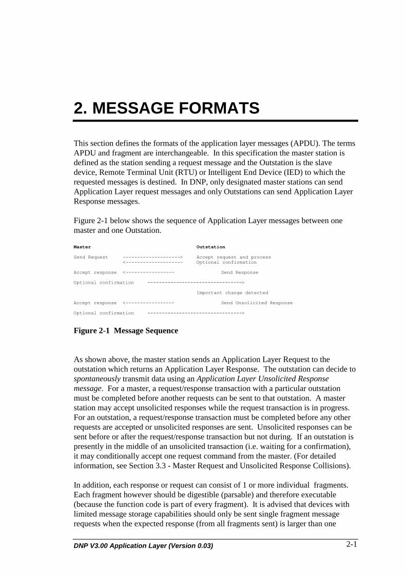
DNP V3.00 Application Layer (Version 0.03) 2-1
2. MESSAGE FORMATS
This section defines the formats of the application layer messages (APDU). The termsAPDU and fragment are interchangeable. In this specification the master station isdefined as the station sending a request message and the Outstation is the slavedevice, Remote Terminal Unit (RTU) or Intelligent End Device (IED) to which therequested messages is destined. In DNP, only designated master stations can sendApplication Layer request messages and only Outstations can send Application LayerResponse messages.
Figure 2-1 below shows the sequence of Application Layer messages between onemaster and one Outstation.
Master Outstation
Send Request --------------------> Accept request and process<-------------------- Optional confirmation
Accept response <----------------- Send Response
Optional confirmation --------------------------------->
Important change detected
Accept response <----------------- Send Unsolicited Response
Optional confirmation --------------------------------->
Figure 2-1 Message Sequence
As shown above, the master station sends an Application Layer Request to theoutstation which returns an Application Layer Response. The outstation can decide tospontaneously transmit data using an Application Layer Unsolicited Responsemessage. For a master, a request/response transaction with a particular outstationmust be completed before another requests can be sent to that outstation. A masterstation may accept unsolicited responses while the request transaction is in progress.For an outstation, a request/response transaction must be completed before any otherrequests are accepted or unsolicited responses are sent. Unsolicited responses can besent before or after the request/response transaction but not during. If an outstation ispresently in the middle of an unsolicited transaction (i.e. waiting for a confirmation),it may conditionally accept one request command from the master. (For detailedinformation, see Section 3.3 - Master Request and Unsolicited Response Collisions).
In addition, each response or request can consist of 1 or more individual fragments.Each fragment however should be digestible (parsable) and therefore executable(because the function code is part of every fragment). It is advised that devices withlimited message storage capabilities should only be sent single fragment messagerequests when the expected response (from all fragments sent) is larger than one

DNP Users Group2-2
fragment. This is to ensure that devices can process a request and build and moreimportantly send a response before the next request is received. Otherwise, multi-fragment messages may require multi-fragment responses which may require moremessage storage than the device has available.
2.1 APPLICATION REQUEST FORMAT
The application request message format (APDU) is illustrated in Figure 2-2. TheAPDU is made up of an APCI block which contains message control information andan ASDU which contains information to be processed by the receiving station. TheAPCI is often called a request header in an application request message. In DNP, theASDU is optional and is used when the message meaning is not conveyed completelyin the request header. The request header contains information on how to assemble amulti-fragment message and on the purpose of the message. The request header ispresent in all application layer request APDUs. If the request header implies all theneeded information required to carry out the request, the ASDU is not present.
Each ASDU consists of one or more Data Unit Identifiers (DUI) or object headers andoptional associated Information Objects (IO) or data fields. The object header canspecify 0 or more en that returned by the receiving station or that follow the header inthe message.
│ DUI │ IO .. IO │ DUI │ IO │┌────────────────┼────────────────┼──────┐ ....├───────────────┼──────┤│ Request Header │ Object Header │ data │ │ Object Header │ data ││ │ │ │ │ │ │├────────────────┼────────────────┴──────┘.....└───────────────┴──────┤│ APCI │ ASDU │
Figure 2-2 Application Request Format
Request Header The request header identifies the purpose of the message andconsists of APCI (Application Protocol Control Information).
Object Header This header identifies the data objects that follow.Data Data object(s) of the type specified in the object header.
2.2 APPLICATION RESPONSE FORMAT
The response from an Outstation to an application layer request APDU or theunsolicited response from an outstation have the format illustrated in Figure 2-3. Theformat is identical in form to the request. The APCI is often called a response headerin an application response message. The response header contains the sameinformation as the request header plus an additional field containing internalindications of the outstation. The response header is always part of the applicationresponse. The response ASDU has the same format of the request message with onenotable exception (explained in Section 3).

DNP V3.00 Application Layer (Version 0.03) 2-3
│ DUI │ IO .. IO │ DUI │ IO │┌────────────────┼────────────────┼──────┐ ....├───────────────┼──────┤│ Response Header│ Object Header │ data │ │ Object Header │ data ││ │ │ │ │ │ │├────────────────┼────────────────┴──────┘.... └───────────────┴──────┤│ APCI │ ASDU │
Figure 2-3 Application Response Format
Response Header The response header identifies the purpose of the message andconsists of APCI (Application Protocol Control Information).
Object Header This header identifies the data objects that follow.Data Data object(s) of the type specified in the object header.

DNP Users Group2-4

DNP V3.00 Application Layer (Version 0.03) 3-1
3. DEFINITION OF DNP MESSAGEFIELDS
This section describes the request and response headers (APCIs) which control thesequence and flow of application messages between a master station and anOutstation, and the ASDU which include DUI or data object headers. The headers areused to assemble multi-fragment (multi-APDU) messages into Application User Data.The object headers are used to identify uniquely the information object(s) thatoptionally follow the header.
3.1 APPLICATION HEADERS
3.1.1 Request Header
The request header or APCI has two fields. Each field is one octet in length and isillustrated below.
┌─────────────────────┬───────────────┐│ Application Control │ Function Code ││ AC │ FC │└─────────────────────┴───────────────┘
Figure 3-1 Request Header
3.1.2 Response Header
The response header has three fields as illustrated below.
┌─────────────────────┬───────────────┬──────────────────────┐│ Application Control │ Function Code │ Internal Indications ││ AC │ FC │ IIN ││ │ │ │└─────────────────────┴───────────────┴──────────────────────┘
Figure 3-2 Response Header
3.1.3 Application Control
The application control field has a size of one octet. It provides information needed toconstruct multi-fragment application messages.
Application messages may be packaged into fragments, with each fragment smallenough to fit into the application's message buffer. The recommended size of thefragment buffer is 2048 bytes in order to maintain compatibility with current DNP
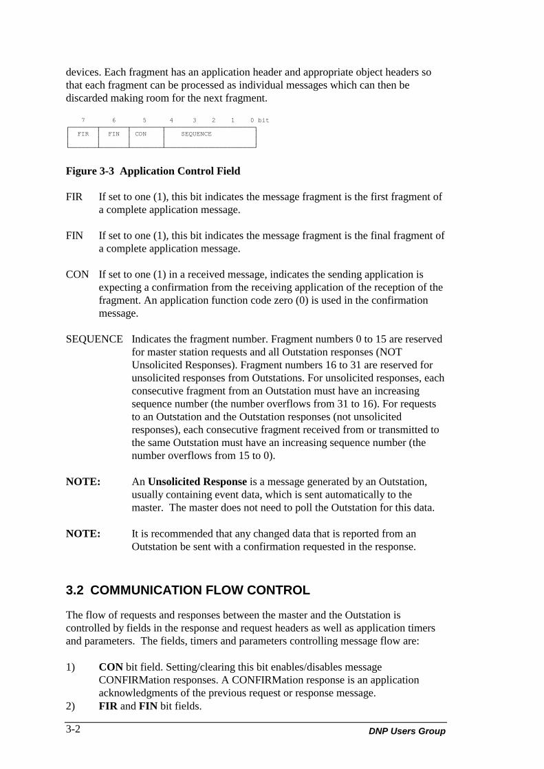
DNP Users Group3-2
devices. Each fragment has an application header and appropriate object headers sothat each fragment can be processed as individual messages which can then bediscarded making room for the next fragment.
7 6 5 4 3 2 1 0 bit┌───────┬───────┬────────┬───────────────────────┐│ FIR │ FIN │ CON │ SEQUENCE ││ │ │ │ │└───────┴───────┴────────┴───────────────────────┘
Figure 3-3 Application Control Field
FIR If set to one (1), this bit indicates the message fragment is the first fragment ofa complete application message.
FIN If set to one (1), this bit indicates the message fragment is the final fragment ofa complete application message.
CON If set to one (1) in a received message, indicates the sending application isexpecting a confirmation from the receiving application of the reception of thefragment. An application function code zero (0) is used in the confirmationmessage.
SEQUENCE Indicates the fragment number. Fragment numbers 0 to 15 are reservedfor master station requests and all Outstation responses (NOTUnsolicited Responses). Fragment numbers 16 to 31 are reserved forunsolicited responses from Outstations. For unsolicited responses, eachconsecutive fragment from an Outstation must have an increasingsequence number (the number overflows from 31 to 16). For requeststo an Outstation and the Outstation responses (not unsolicitedresponses), each consecutive fragment received from or transmitted tothe same Outstation must have an increasing sequence number (thenumber overflows from 15 to 0).
NOTE: An Unsolicited Response is a message generated by an Outstation,usually containing event data, which is sent automatically to themaster. The master does not need to poll the Outstation for this data.
NOTE: It is recommended that any changed data that is reported from anOutstation be sent with a confirmation requested in the response.
3.2 COMMUNICATION FLOW CONTROL
The flow of requests and responses between the master and the Outstation iscontrolled by fields in the response and request headers as well as application timersand parameters. The fields, timers and parameters controlling message flow are:
1) CON bit field. Setting/clearing this bit enables/disables messageCONFIRMation responses. A CONFIRMation response is an applicationacknowledgments of the previous request or response message.
2) FIR and FIN bit fields.

DNP V3.00 Application Layer (Version 0.03) 3-3
3) Sequence Number field. This number is used to assemble multi-fragmentmessages and identify which responses match particular requests.
4) Master station and Outstation application response time-outs. These specifyhow long an application must wait for a response or CONFIRMation responsebefore re-transmitting or aborting the transaction. The application may or maynot support re-transmission of transactions at the application layer.
5) Master station and Outstation application retry count. Applications may ormay not support application level retries. Retry counters specify how manytimes a request is repeated if a response fails, or how often responses are re-transmitted if a CONFIRMation response is not received.
An Outstation must completely process a request and respond to it before beginning toprocess a second request. It cannot simultaneously process multiple requests.
The Sequence Number for all requests from the master station to the Outstationis in the range 0 to 15 inclusive. The sequence number for all UnsolicitedResponses from the Outstation is in the range 16 to 31 inclusive.
The following rules dictate how sequence numbers work:• The sequence number rolls over from 15 to 0 or from 31 to 16. Each successive
request fragment from the DNP master station has an incremented sequencenumber. The exception is for retries on requests. For single fragment requestretries, the sequence number is NOT incremented. For multi fragment requestretries, the sequence number of the first fragment of the request retry equals thesequence number of the last fragment of the request which has just failed.
• A single fragment response to a single fragment request has the same sequencenumber as the request.
• The CONFIRMation response to a request or response has the same sequencenumber as the request or response.
• The first fragment of a multi-fragment response to a single fragment request has thesame sequence number as the request. For successive fragment of the multi-fragment response, the sequence number is incremented.
• The first fragment of a multi-fragment response to a multi-fragment request has thesame sequence number as the last fragment of the multi-fragment request.
The use of this sequence number scheme ensures the Outstation and master stationcan cope with all occurrences of messages being lost or delayed on a communicationnetwork. The following rules are obeyed by both the Outstation and master station:• If the system uses application level retries, when a response is not received before
time-out, the request will be re-transmitted with the same sequence number.• If two messages are received with the same sequence number, it usually means that
the response to the message was not received by the other station. In this case,retransmit the response (re-processing the message is unnecessary).
• If two CONFIRMation responses are received with the same sequence number,ignore the second response.
The following figures illustrate some cases of message transactions and how theSequence Numbers prevent problems. In the examples, SEQ is the Sequence Numberand CON is the Confirmation Requested bit in the message. Time progresses from left

DNP Users Group3-4
to right in the diagrams. The vertical arrows represent the flow of messages betweenthe Outstation and the master station.
Case One illustrates typical message transactions. The master sends a request, theOutstation responds and the master CONFIRMs the response. Later on, the Outstationsends an Unsolicited Response to the master station. When the Outstation transmitsthe response, it starts a CONFIRMation response timer. If this timer had expiredbefore the CONFIRMation was received, the Outstation would have re-transmitted theresponse.
Case Two shows a similar situation to Case One except the master request requires aCONFIRMation response as well as a normal response.
CASE 1 Time ────────────────────────────────────────────────────────────→Master │ Request. │ │ │ Response │ CONFIRM │ CONFIRM │ expected. │ (SEQ=7) │ (SEQ=24) │ (CON=0) │ │ │ (SEQ=7) │ │ ▼ ▼ ▼ --------------------------------------------------------------------Outstation ▲ ▲ │ Response │ Unsol. │ to master │ Response │ (CON=1) │ (CON=1) │ (SEQ=7) │ (SEQ=24) │ │
CASE 2 Time ────────────────────────────────────────────────────────────→Master │ Request. │ │ Response │ CONFIRM │ expected. │ (SEQ=2) │ (CON=0) │ │ (SEQ=2) │ ▼ ▼ --------------------------------------------------------------------Outstation ▲ ▲ │ CONFIRM │ Response │ (SEQ=2) │ to master │ │ request │ │ (CON=1) │ │ (SEQ=2)
Figure 3-4 Typical Message Transaction Flow
NOTE: In Figure 3-4 and some of the following figures, the CON bit is set inthe Outstation responses. The CON bit may be clear in sometransaction (e.g. when the response does not contain event data). In thiscase, data loss due to communication loss is often not critical. TheOutstation assumes that the response was successful.
Case Three illustrates a multi-fragment response from the Outstation. The sequencenumber in successive fragments is incremented. Note that the next request from themaster station used sequence number equals 4.
In Case Four, the response from the Outstation is not received by the master station.The Outstation waits for a CONFIRMation, and when its CONFIRMation time-outexpires it re-transmits the response.

DNP V3.00 Application Layer (Version 0.03) 3-5
CASE 3 Time ────────────────────────────────────────────────────────────→Master │ Request. │ │ │ Request. │ Response │ CONFIRM │ CONFIRM │ (SEQ=4) │ expected. │ (SEQ=2) │ (SEQ=24) │ │ (CON=0) │ │ │ │ (SEQ=2) │ │ │ ▼ ▼ ▼ ▼ --------------------------------------------------------------------Outstation ▲ ▲ │ Response │ Response │ Frag. 1 │ Frag. 2 │ (CON=1) │ (CON=1) │ (SEQ=2) │ (SEQ=3) │ │
CASE 4 Time ────────────────────────────────────────────────────────────→Master │ Request. │ │ Response Response │ CONFIRM │ expected. not │ (SEQ=3) │ (CON=0) received. │ │ (SEQ=3) │ ▼ ▼ --------------------------------------------------------------------Outstation ▲ ▲ │ Response CONFIRM not │ Response │ (CON=1) received. RTU │ (CON=1) │ (SEQ=3) time-out. Resend │ (SEQ=3) │ response. │ │ │
Figure 3-5 Multi-Fragment Response & RTU Confirmation Time-out
From the Outstation side, Case Five is identical to Case Four. In Case Five unlikeCase Four, the master does CONFIRM the first Outstation response. ThisCONFIRMation is not received by the Outstation. When the Outstation resends theresponse, the master will repeat the CONFIRMation. The master will not re-processthe second response.
Case Six illustrates the case where the master request is not received by theOutstation. The master repeats the request after a response time-out occurs.

DNP Users Group3-6
CASE 5 Time ────────────────────────────────────────────────────────────→Master │ Request. │ │ │ Response │ CONFIRM │ CONFIRM │ expected. │ (SEQ=10) │ (SEQ=10) │ (CON=0) │ │ │ (SEQ=10) │ │ ▼ ▼ ▼ --------------------------------------------------------------------Outstation ▲ ▲ │ Response CONFIRM not │ Response │ (CON=1) received. RTU │ (CON=1) │ (SEQ=10) time-out. Resend │ (SEQ=10) │ response. │ │ │
CASE 6 Time ────────────────────────────────────────────────────────────→Master │ Request. Time-out on │ Request. │ │ Response response. │ Response │ CONFIRM │ expected. Resend │ expected. │ (SEQ=5) │ (CON=0) Request. │ (CON=0) │ │ (SEQ=5 ) │ (SEQ=5) │ ▼ ▼ ▼ --------------------------------------------------------------------Outstation ▲ Request not │ Response received. │ (CON=1) │ (SEQ=5) │ │
Figure 3-6 Message Transactions With Response Time-outs
Case Seven is similar to Case Four. In both cases, the Outstation response to themaster request is not received. In Case Four the Outstation timed out waiting for theCONFIRMation and repeated the response. In Case Seven however, the master timesout first and repeats the request. The Outstation automatically stops waiting for theCONFIRMation and repeats its previous response. Case Seven also illustrates anotherpossible condition. The original response that the master did not receive is delayed inthe communication network. The master re-sends the request, the Outstation repliesand the master finishes the transaction sequence with a CONFIRMation. The originalresponse from the Outstation then arrives at the master station. The master stationassumes that the first CONFIRMation was not received by the Outstation. It thereforere-transmits the CONFIRMation. The Outstation receives and discards this secondCONFIRMation.
Case Eight is similar to Case Seven. In this case, the first CONFIRMation from theOutstation is delayed in the communication network. When this CONFIRMationeventually arrives at the master station, it is ignored.

DNP V3.00 Application Layer (Version 0.03) 3-7
CASE 7 Time ────────────────────────────────────────────────────────────→Master │ Request. Response │ Request. │ │ │ Response not received. │ Response │ CONFIRM │ CONFIRM │ expected. Resend │ expected. │ (SEQ=8) │ (SEQ=8) │ (CON=0) request. │ (CON=0) │ │ │ (SEQ=8) │ (SEQ=8) │ │ ▼ ▼ ▼ ▼ --------------------------------------------------------------------Outstation ▲ ▲ │ Response │ Response RTU ignores │ (CON=1) │ (CON=1) second │ (SEQ=8) │ (SEQ=8) CONFIRM │ │ │ │
CASE 8 Time ────────────────────────────────────────────────────────────→Master │ Request. CONFIRM delayed │ Request. Master receives │ No response in network. │ No response first delayed │ expected. Time-out. Master │ expected. CONFIRM and │ (CON=0) resends request. │ (CON=1) ignores it. │ (SEQ=5 ) │ (SEQ=12) ▼ ▼ --------------------------------------------------------------------Outstation ▲ ▲ │ CONFIRM │ CONFIRM │ (SEQ=12) │ (SEQ=12) │ │ │ │ │ │
Figure 3-7 Message Flow When Response Delayed on a Network
In Case Nine, the Unsolicited Response is re-transmitted by the Outstation when atime-out on the CONFIRMation occurs. The master eventually receives it twice. Itdoes not process it the second time, but does respond to it in the same way as the firsttime. The Outstation discards the second CONFIRMation. This illustrates a situationwhere network delays, and not message losses, cause time-outs to occur.
CASE 9 Time ────────────────────────────────────────────────────────────→Master Unsol. response │ Master │ delayed in │ CONFIRM receives the │ CONFIRM network. │ (SEQ=30) delayed unsol. │ (SEQ=30) Not received. │ response. │ │ Resend CONFIRM. │ ▼ ▼ --------------------------------------------------------------------Outstation ▲ ▲ │ Unsol. Time-out on │ Unsol. RTU discards │ response. CONFIRM │ Response. second │ (CON=1) Resend. │ (CON=1) CONFIRM. │ (SEQ=30) │ (SEQ=30) │ │
Figure 3-8 Resending Unsolicited Responses Due to Network Delays

DNP Users Group3-8
3.3 MASTER REQUEST & UNSOLICITED RESPONSECOLLISIONS
When Unsolicited Responses are generated by an Outstation there exists thepossibility that the master station sends a request at the same time that the Outstationsends an Unsolicited Response. The Outstation may receive the request when itexpects to receive a CONFIRMation of its Unsolicited Response. The master receivesthe Unsolicited Response when it expects to receive a response to its request.
The processing of the above and similar situation depends on the type of requestissued by the master station.
The master station will always process an Unsolicited Response immediately, ever ifit arrives when the master station is expecting a response to a previously issuedrequest. A CONFIRMation of the Unsolicited Response is issued immediately ifrequested by the Outstation (i.e. if CON bit is set).
The Outstation will generally process a request immediately, even if it is waiting forCONFIRMation of a previous Unsolicited Response. All requests except READrequests for system data (e.g. Binary input data, counter event data etc.) are processedin this way. This mode of operation is referred to as IMMEDIATE_PROCESS mode.
The Outstation will NOT process a master station READ request if it is waiting forCONFIRMation of a previous Unsolicited Response. It will wait for theCONFIRMation before processing the request. The reason for the differentfunctionality is to prevent the loss or duplication of data events. This mode ofoperation is referred to PROCESS_AFTER_CONFIRM mode.
3.3.1 IMMEDIATE_PROCESS Mode
Figures 3-9 and 3-10 illustrate the normal functionality when a master station requestand an Outstation Unsolicited Response are transmitted simultaneously and theOutstation is in the IMMEDIATE_PROCESS mode (i.e. request is not a READrequest).
In Case Ten, the master immediately responds to the Unsolicited Response. TheOutstation immediately processes and responds to the master station request. Notethat the two CONFIRMation responses could be sent from the master in the oppositeorder to the order shown in Case Ten. This would not confuse the Outstation.
Case Eleven illustrates a basic message flow where the Unsolicited Response does notrequire a CONFIRMation.

DNP V3.00 Application Layer (Version 0.03) 3-9
CASE 10 Time ────────────────────────────────────────────────────────────→Master │ Request. │ │ │ Response │ CONFIRM │ CONFIRM │ expected. │ (SEQ=7) │ (SEQ=24) │ (CON=0) │ │ │ (SEQ=7) │ │ ▼ ▼ ▼ --------------------------------------------------------------------Outstation ▲ ▲ │ Unsol. │ Response │ Response │ to master │ (CON=1) │ request │ (SEQ=24) │ (CON=1) │ │ (SEQ=7)
CASE11 Time ────────────────────────────────────────────────────────────→Master │ Request. Store and │ │ Response process the │ CONFIRM │ expected. unsol. response. │ (SEQ=2) │ (CON=1) │ │ (SEQ=2) │ ▼ ▼ --------------------------------------------------------------------Outstation ▲ ▲ ▲ │ Unsol. │ CONFIRM │ Response │ response │ (SEQ=2) │ to master │ (CON=0) │ │ request │ (SEQ=22) │ │ (CON=1) │ │ │ (SEQ=2)
Figure 3-9 Simultaneous Transmissions, IMMEDIATE_PROCESS Mode
In Case Twelve, the Unsolicited Response is CONFIRMed in betweenCONFIRMations to two fragments of a multi-fragment response to the master request.
Case Thirteen illustrates the situation where the Unsolicited Response is not receivedby the master station. The Outstation responds to the master request, then after theCONFIRMation time-out for the Unsolicited Response, the Outstation re-transmitsthe Unsolicited Response. The master then CONFIRMs the Unsolicited Response.Note that it is possible that the first Unsolicited Response later arrives at the masterstation (it was delayed in the network). The master would not re-process the response,but would reply to it again. The Outstation would discard the reply.
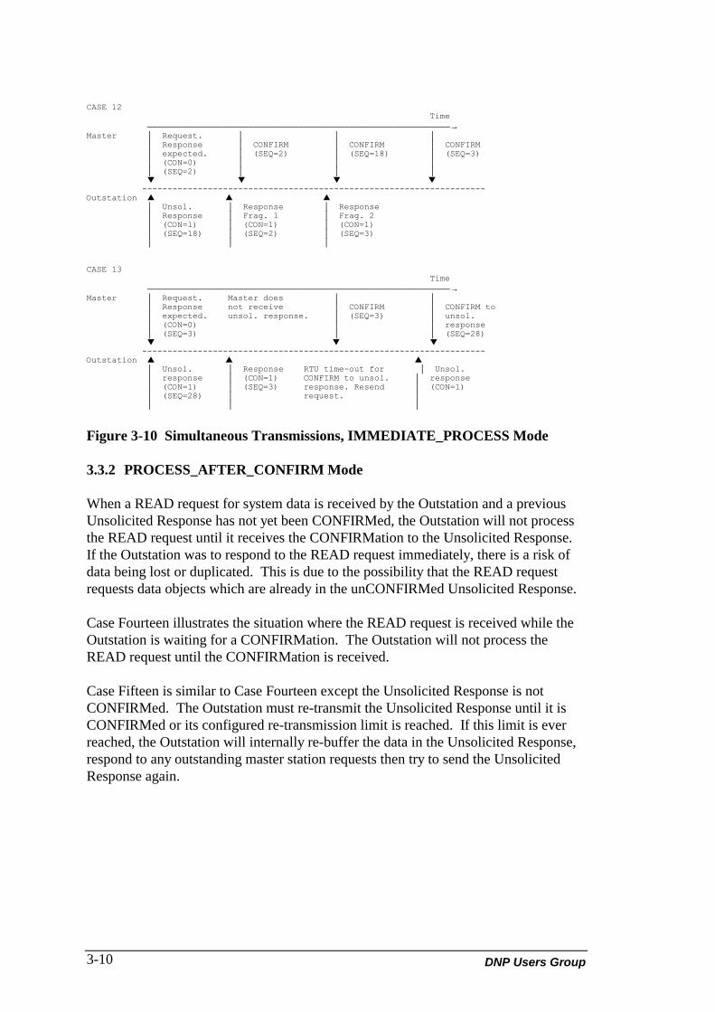
DNP Users Group3-10
CASE 12 Time ────────────────────────────────────────────────────────────→Master │ Request. │ │ │ │ Response │ CONFIRM │ CONFIRM │ CONFIRM │ expected. │ (SEQ=2) │ (SEQ=18) │ (SEQ=3) │ (CON=0) │ │ │ │ (SEQ=2) │ │ │ ▼ ▼ ▼ ▼ --------------------------------------------------------------------Outstation ▲ ▲ ▲ │ Unsol. │ Response │ Response │ Response │ Frag. 1 │ Frag. 2 │ (CON=1) │ (CON=1) │ (CON=1) │ (SEQ=18) │ (SEQ=2) │ (SEQ=3) │ │ │
CASE 13 Time ────────────────────────────────────────────────────────────→Master │ Request. Master does │ │ │ Response not receive │ CONFIRM │ CONFIRM to │ expected. unsol. response. │ (SEQ=3) │ unsol. │ (CON=0) │ │ response │ (SEQ=3) │ │ (SEQ=28) ▼ ▼ ▼ --------------------------------------------------------------------Outstation ▲ ▲ ▲ │ Unsol. │ Response RTU time-out for │ Unsol. │ response │ (CON=1) CONFIRM to unsol. │ response │ (CON=1) │ (SEQ=3) response. Resend │ (CON=1) │ (SEQ=28) │ request. │ │ │ │
Figure 3-10 Simultaneous Transmissions, IMMEDIATE_PROCESS Mode
3.3.2 PROCESS_AFTER_CONFIRM Mode
When a READ request for system data is received by the Outstation and a previousUnsolicited Response has not yet been CONFIRMed, the Outstation will not processthe READ request until it receives the CONFIRMation to the Unsolicited Response.If the Outstation was to respond to the READ request immediately, there is a risk ofdata being lost or duplicated. This is due to the possibility that the READ requestrequests data objects which are already in the unCONFIRMed Unsolicited Response.
Case Fourteen illustrates the situation where the READ request is received while theOutstation is waiting for a CONFIRMation. The Outstation will not process theREAD request until the CONFIRMation is received.
Case Fifteen is similar to Case Fourteen except the Unsolicited Response is notCONFIRMed. The Outstation must re-transmit the Unsolicited Response until it isCONFIRMed or its configured re-transmission limit is reached. If this limit is everreached, the Outstation will internally re-buffer the data in the Unsolicited Response,respond to any outstanding master station requests then try to send the UnsolicitedResponse again.
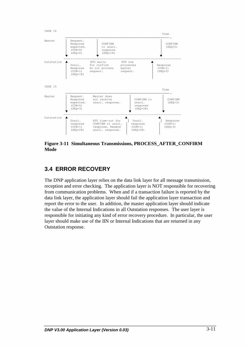
DNP V3.00 Application Layer (Version 0.03) 3-11
CASE 14 Time ────────────────────────────────────────────────────────────→Master │ Request. │ │ │ Response │ CONFIRM │ CONFIRM │ expected. │ to unsol. │ (SEQ=2) │ (CON=0) │ response │ │ (SEQ=2) │ (SEQ=18) │ ▼ ▼ ▼ --------------------------------------------------------------------Outstation ▲ RTU waits RTU now ▲ │ Unsol. for confirm processes │ Response │ Response Do not process master │ (CON=1) │ (CON=1) request. request. │ (SEQ=2) │ (SEQ=18) │ │ │
CASE 15 Time ────────────────────────────────────────────────────────────→Master │ Request. Master does │ │ │ Response not receive │ CONFIRM to │ CONFIRM │ expected. unsol. response. │ unsol. │ (SEQ=3) │ (CON=0) │ response │ │ (SEQ=3) │ (SEQ=28) │ ▼ ▼ ▼ --------------------------------------------------------------------Outstation ▲ ▲ ▲ │ Unsol. RTU time-out for │ Unsol. │ Response │ response CONFIRM to unsol. │ response │ (CON=1) │ (CON=1) response. Resend │ (CON=1) │ (SEQ=3) │ (SEQ=28) unsol. response. │ (SEQ=28) │ │ │ │
Figure 3-11 Simultaneous Transmissions, PROCESS_AFTER_CONFIRMMode
3.4 ERROR RECOVERY
The DNP application layer relies on the data link layer for all message transmission,reception and error checking. The application layer is NOT responsible for recoveringfrom communication problems. When and if a transaction failure is reported by thedata link layer, the application layer should fail the application layer transaction andreport the error to the user. In addition, the master application layer should indicatethe value of the Internal Indications in all Outstation responses. The user layer isresponsible for initiating any kind of error recovery procedure. In particular, the userlayer should make use of the IIN or Internal Indications that are returned in anyOutstation response.

DNP Users Group3-12
3.5 FUNCTION CODES
The function code identifies the purpose of the message. The size of this field is oneoctet. There are two groups of function codes; one for requests and the other forresponses.
CODE FUNCTION DESCRIPTION
Transfer Function Codes
0 Confirm Message fragment confirmation used inboth requests and responses. Noresponse to this message is required.
1 Read Request specified objects from Outstation;respond with objects requested that areavailable.
2 Write Store specified objects in Outstation;respond with status of the operation
Control Function Codes
3 Select Select or arm output points but do not setor produce any output action (controls,setpoints, analog outputs) ; respond withthe status of the control points selected.The Operate function code is required toactivate these outputs.
4 Operate Set or produce the output actions on thepoints previously selected with the Selectfunction; respond with the status of thecontrol points.
5 Direct Operate Select and set or operate the specifiedoutputs; respond with the status of thecontrol points.
6 Direct Operate- NoAcknowledgment
Select and set or operate the specifiedoutputs but do not send a response to therequest.
Freeze Function Codes
7 Immediate Freeze Copy the specified objects to a freezebuffer and respond with status of theoperation.
8 Immediate Freeze-No Acknowledgment
Copy the specified objects to a freezebuffer; do not respond with a message.
Transfer Function Codes
9 Freeze and Clear Copy the specified objects to a freezebuffer, then clear the objects; respond withthe status of the operation.
10 Freeze and Clear-No Acknowledgment
Copy the specified objects to a freezebuffer, then clear the objects; do notrespond with a message.

DNP V3.00 Application Layer (Version 0.03) 3-13
CODE FUNCTION DESCRIPTION
11 Freeze with Time Copy the specified objects to a freezebuffer at the specified time and intervals;respond with the status of the operation.
12 Freeze with Time-No Acknowledgment
Copy the specified objects to a freezebuffer at the specified time and intervals;do not respond with a message.
Application Control Function Codes
13 Cold Restart Perform the desired reset sequence;respond with a time object indicating timetill Outstation availability.
14 Warm Restart Perform the desired partial reset sequence;respond with a time object indicating timetill Outstation availability.
15 Initialize Data toDefaults
Initialize the specified data to power upinitial values; respond with status of theoperation.
16 Initialize Application Ready the specified application(s) to run;respond with status of the operation.
17 Start Application Start running the specified application(s);respond with status of the operation.
18 Stop Application Stop the specified application(s); respondwith status of the operation.
Configuration Function Codes
19 Save Configuration Save the specified configuration to non-volatile memory; respond with a time objectindicating time till Outstation availability.
20 Enable UnsolicitedMessages
Enable spontaneous reporting of thespecified data object(s); respond withstatus of the operation
21 Disable UnsolicitedMessages
Disable spontaneous reporting of thespecified data object(s); respond withstatus of the operation
22 Assign Class Assigned specified data object(s) to aparticular class
Time Synchronization Function Codes
23 Delay Measurement Allows the application to calculate the pathdelay (or propagation delay) for a particularOutstation. The value calculated from thisfunction code should be used to adjust thetime of day when setting the Outstationtime.
Reserved
24 - 120 Reserved for future use
121 - 128 Reserved for testing only
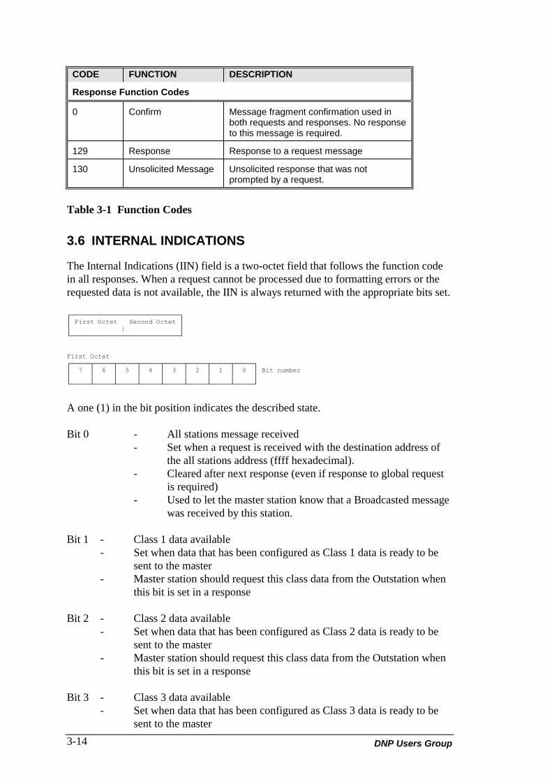
DNP Users Group3-14
CODE FUNCTION DESCRIPTION
Response Function Codes
0 Confirm Message fragment confirmation used inboth requests and responses. No responseto this message is required.
129 Response Response to a request message
130 Unsolicited Message Unsolicited response that was notprompted by a request.
Table 3-1 Function Codes
3.6 INTERNAL INDICATIONS
The Internal Indications (IIN) field is a two-octet field that follows the function codein all responses. When a request cannot be processed due to formatting errors or therequested data is not available, the IIN is always returned with the appropriate bits set.
┌────────────────────────────┐│ First Octet Second Octet ││ | │└────────────────────────────┘
First Octet┌─────┬─────┬─────┬─────┬─────┬─────┬─────┬─────┐│ 7 │ 6 │ 5 │ 4 │ 3 │ 2 │ 1 │ 0 │ Bit number│ │ │ │ │ │ │ │ │└─────┴─────┴─────┴─────┴─────┴─────┴─────┴─────┘
A one (1) in the bit position indicates the described state.
Bit 0 - All stations message received- Set when a request is received with the destination address of
the all stations address (ffff hexadecimal).- Cleared after next response (even if response to global request
is required)- Used to let the master station know that a Broadcasted message
was received by this station.
Bit 1 - Class 1 data available- Set when data that has been configured as Class 1 data is ready to be
sent to the master- Master station should request this class data from the Outstation when
this bit is set in a response
Bit 2 - Class 2 data available- Set when data that has been configured as Class 2 data is ready to be
sent to the master- Master station should request this class data from the Outstation when
this bit is set in a response
Bit 3 - Class 3 data available- Set when data that has been configured as Class 3 data is ready to be
sent to the master
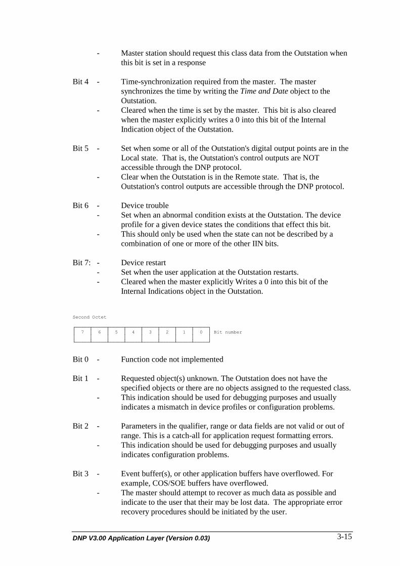
DNP V3.00 Application Layer (Version 0.03) 3-15
- Master station should request this class data from the Outstation whenthis bit is set in a response
Bit 4 - Time-synchronization required from the master. The mastersynchronizes the time by writing the Time and Date object to theOutstation.
- Cleared when the time is set by the master. This bit is also clearedwhen the master explicitly writes a 0 into this bit of the InternalIndication object of the Outstation.
Bit 5 - Set when some or all of the Outstation's digital output points are in theLocal state. That is, the Outstation's control outputs are NOTaccessible through the DNP protocol.
- Clear when the Outstation is in the Remote state. That is, theOutstation's control outputs are accessible through the DNP protocol.
Bit 6 - Device trouble- Set when an abnormal condition exists at the Outstation. The device
profile for a given device states the conditions that effect this bit.- This should only be used when the state can not be described by a
combination of one or more of the other IIN bits.
Bit 7: - Device restart- Set when the user application at the Outstation restarts.- Cleared when the master explicitly Writes a 0 into this bit of the
Internal Indications object in the Outstation.
Second Octet
┌─────┬─────┬─────┬─────┬─────┬─────┬─────┬─────┐│ 7 │ 6 │ 5 │ 4 │ 3 │ 2 │ 1 │ 0 │ Bit number│ │ │ │ │ │ │ │ │└─────┴─────┴─────┴─────┴─────┴─────┴─────┴─────┘
Bit 0 - Function code not implemented
Bit 1 - Requested object(s) unknown. The Outstation does not have thespecified objects or there are no objects assigned to the requested class.
- This indication should be used for debugging purposes and usuallyindicates a mismatch in device profiles or configuration problems.
Bit 2 - Parameters in the qualifier, range or data fields are not valid or out ofrange. This is a catch-all for application request formatting errors.
- This indication should be used for debugging purposes and usuallyindicates configuration problems.
Bit 3 - Event buffer(s), or other application buffers have overflowed. Forexample, COS/SOE buffers have overflowed.
- The master should attempt to recover as much data as possible andindicate to the user that their may be lost data. The appropriate errorrecovery procedures should be initiated by the user.

DNP Users Group3-16
Bit 4 - Request understood but requested operation is already executing.
Bit 5 - Set to indicate that the current configuration in the Outstation is corruptand that the master application layer should inform the user of thisexception. The master may download another configuration to theOutstation. Note that sometimes a corrupt configuration will disablean Outstation, making it impossible to communicate this condition to amaster station.
Bit 6 - Reserved for use by agreement, currently always returned as zero (0).
Bit 7 - Reserved for use by agreement, currently always returned as zero (0).
3.7 OBJECT HEADER
The object header of a message specifies the data objects (or IOs) that are eithercontained in the message or are to be used to respond to this message. The format ofthe object header is identical for a request and a response but the interpretation of theheader is dependent on whether it is a request or a response and which function codeaccompanies the header.
┌────────┬───────────┬───────┐│ Object │ Qualifier │ Range ││ │ │ │└────────┴───────────┴───────┘
Figure 3-12 Object Header
Object Specifies the object group and variation of the objects that follow theheader as described in section 3. OBJECT. This is a two-octet field.The object field uniquely identifies the type or class of object whichgives the structure (and hence size) of the data object.
Qualifier Specifies the meaning of the range field as described in section 3.QUALIFIER. This is a one-octet field. The qualifier specifies how therange field is to be interpreted.
Range Indicates the quantity of objects, starting and ending index oridentifiers for the objects in question as described in section 3. Thisfield uniquely identifies the objects in question.
NOTE: The range field may not be present if the qualifier specifies that there isno range field. The size of this field ranges from zero (0) octets to eightoctets.
3.7.1 Object Field
The Object field specifies an object group and the variation of the object within thegroup. The combined object group plus variation specifies uniquely the object towhich the message refers. The currently defined object structures are described inDNP-V3.00 Data Object Library (P009-0BL).
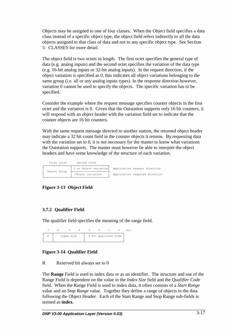
DNP V3.00 Application Layer (Version 0.03) 3-17
Objects may be assigned to one of four classes. When the Object field specifies a dataclass instead of a specific object type, the object field refers indirectly to all the dataobjects assigned to that class of data and not to any specific object type. See Section5: CLASSES for more detail.
The object field is two octets in length. The first octet specifies the general type ofdata (e.g. analog inputs) and the second octet specifies the variation of the data type(e.g. 16-bit analog inputs or 32-bit analog inputs). In the request direction, if theobject variation is specified as 0, this indicates all object variations belonging to thesame group (i.e. all or any analog inputs types). In the response direction however,variation 0 cannot be used to specify the objects. The specific variation has to bespecified.
Consider the example where the request message specifies counter objects in the firstoctet and the variation is 0. Given that the Outstation supports only 16 bit counters, itwill respond with an object header with the variation field set to indicate that thecounter objects are 16 bit counters.
With the same request message directed to another station, the returned object headermay indicate a 32 bit count field in the counter objects it returns. By requesting datawith the variation set to 0, it is not necessary for the master to know what variationsthe Outstation supports. The master must however be able to interpret the objectheaders and have some knowledge of the structure of each variation.
first octet second octet┌────────────────┬──────────────────────┐│ │ 0 or Object variation│ Application request direction│ Object Group ├──────────────────────┤│ │ Object variation │ Application response direction└────────────────┴──────────────────────┘
Figure 3-13 Object Field
3.7.2 Qualifier Field
The qualifier field specifies the meaning of the range field.
7 6 5 4 3 2 1 0 bit┌─────┬──────────────────┬───────────────────────┐│ R │ Index Size │ 4 bit Qualifier Code ││ │ │ │└─────┴──────────────────┴───────────────────────┘
Figure 3-14 Qualifier Field
R Reserved bit always set to 0
The Range Field is used to index data or as an identifier. The structure and use of theRange Field is dependent on the value in the Index Size field and the Qualifier Codefield. When the Range Field is used to index data, it often consists of a Start Rangevalue and an Stop Range value. Together they define a range of objects in the datafollowing the Object Header. Each of the Start Range and Stop Range sub-fields istermed as index.

DNP Users Group3-18
Index Size (3-bits)
• In a Request Object Header when Qualifier Code equals 11
The Index Size bits are valid only when the qualifier code is 11. These bitsindicate the size, in octets, of each entry in the Range Field. The Range Fieldfollows the Qualifier Field. The Range Field consists of indices (to specify arange of objects) or object identifier lists (see qualifier code 11).
0 = not valid with qualifier code 111 = 1 octet identifier size2 = 2 octet identifier size3 = 4 octet identifier size4 = reserved5 = reserved6 = reserved7 = reserved
• In a Response or Request Object Header that is part of a message containing dataobjects.
The 3 bit Index Size field specifies the size of the indices or object sizeprefixing each object.
0 = objects are packed with no index prefixing them1 = objects are prefixed with a 1 octet index2 = objects are prefixed with a 2 octet index3 = objects are prefixed with a 4 octet index4 = objects are prefixed with a 1 octet object size5 = objects are prefixed with a 2 octet object size6 = objects are prefixed with a 4 octet object size7 = reserved
Qualifier Code (4-bits)
The Qualifier Code is used to specify the meaning of the Range field.
• Start and Stop Sub-Fields in the Range Field
The Range field following the Qualifier field often contains sub-fields (StartRange and Stop Range) that designate a range of integer values startingnumerically from Start Range (including the number Start Range) to StopRange (including the number Stop Range).
For Qualifier Codes 0, 1 and 2, Start Range and Stop Range are interpreted asindices of data
For Qualifier Codes 3, 4 and 5, Start Range and Stop Range are interpreted asvirtual memory addresses.

DNP V3.00 Application Layer (Version 0.03) 3-19
The Qualifier Code can be used both in the request and response messages asit can uniquely identify data objects whether they do or do not exist in themessage.
The Index Size field should be 0 in a data-less message to indicate no furtherindexing. The Index Size field can be 4, 5 or 6 in a message with data objectsto indicate that each data object (with indices specified by the Range Field) hasan object size prefix (with this size determines by the Index size). A messagewith data can also use Index size of 0 to indicate no more indexing. ForQualifier Codes specifying Start ad Stop Indices in the Range, Index Sizevalues of 1, 2 and 3 cannot be used.
Some Qualifier Code definitions are:
0 = 8 bit start and stop indices in the Range Field1 = 16 bit start and stop indices in the Range Field2 = 32 bit start and stop indices in the Range Field3 = 8 bit absolute address identifiers in the Range4 = 16 bit absolute address identifiers in the Range5 = 32 bit absolute address identifiers in the Range
• All objects of the given object type
When the Qualifier Field equals 6, the length of the range field is 0 (i.e. norange field) because all the data objects of the specified type are being referredto. This qualifier can be used in messages with object headers only because itcannot uniquely identify data objects if they are present in the message. TheIndex size should be set to 0 when this Qualifier code is used.
Qualifier Code 6 = no range field (implies all the specified objects)
• Single field quantity
Qualifier Codes 7, 8 and 9 are used to indicate that the Range Field consists ofa single count indicating the number of data objects in question. The RangeField that follows designates the number of objects referenced.
If the Index Size field equals zero, the Range Field specifies the number ofobjects referenced starting numerically from 0 (including 0) to the value in theRange Field minus 1.
If the Index Size is 1, 2 or 3 then the Range Field specifies the number ofindices and objects following the Range Field.
Qualifier Codes 7, 8 and 9 can be used in the request and response messages.In a message with or without data objects, the value in the Range Fieldspecifies the number of data objects to be referred to. The Index Size fieldshould be set to the size of the indices that either pre-fix each data object (formessages with data objects) or that form a sequential list of identifiers.

DNP Users Group3-20
The Index Size field should not indicate an object size identifier as this wouldnot uniquely specify the data objects in question and should be set to 0 if noidentifiers or indices are following. The order of identifiers (and optional dataobjects) is arbitrary but should not consist of duplicate indices.
Some Qualifier Code definitions are:
7 = 8 bit single field quantity8 = 16 bit single field quantity9 = 32 bit single field quantity
• Free-format Qualifier (Qualifier Code 11)
This Qualifier Code is used to specify objects when other Qualifier Codes areinadequate or do not provide enough identifying information.
Qualifier 11 is used only when the Range Field (index) cannot uniquelyspecify the data objects in question. In this case, the Qualifier Code defines avariable length array of octets (string) that contains the object identifier.
This identifier has a free-format and will not be interpreted in any way by theapplication layer at this time.
The Range Field is always a 1 octet value (Count) which specifies the numberof object identifiers. Following the Range Field are Count object sizefield/object identifier pairs. The size of the identifier (in octets) is determinedby the object size field which prefixes each identifier. The size of the objectsize field is determined by the Index size. Index sizes 4,5, and 6 should beused to specify the size of the object size field in octets.
• Reserved Qualifier Codes
The following Qualifier Code values are reserved and should not be used:
10 = reserved12 = reserved13 = reserved14 = reserved15 = reserved
3.7.3 Range
The meaning of the Range Field is specified by the Qualifier Field. For QualifierCodes 0 to 5 the Range field has 2 sub-fields specifying a start and stop index oraddress. The values in these fields are inclusive. The Range field is not present forqualifier code 6. The range field is a single field specifying a quantity for qualifiercodes 7, 8, 9 and 11. In the following, the term 'Q-code' refers to the 4 bit QualifierCode field and 'I-size' refers to the Index Size field.

DNP V3.00 Application Layer (Version 0.03) 3-21
The following figure defines all the valid qualifier/range/index combinations for arequest or response which do NOT contain any IO or data objects and simply specifiesthe objects in question. The bytes described appear after the qualifier octet of theobject header and before the next object header or end of message.
Request for known points specified with a Range of indices.
Use Q-code 0-5 for describing points related in sequence:
┌─────────┬─────────┐│ Start │ Stop │ Q-code 0 and 3; I-size MUST be 0│ 8 bit │ 8 bit │ Definition of Range Field.│ │ │ Points are I1 to I2 inclusive│ I1 │ I2 │└─────────┴─────────┘
LSB MSB LSB MSB┌───────────────────┬───────────────────┐│ 16 bit Start │ 16 bit Stop │ Q-code 1 and 4; I-size MUST be 0│ │ │ │ │ Points are I1 to I2 inclusive│ │ │ │ ││ I1 │ I2 ││ │ │└───────────────────┴───────────────────┘
LSB MSB LSB MSB┌───────────────────────────────────────┬─────────────────────────────────────┐│ 32 bit Start │ 32 bit Stop ││ │ │ │ │ │ │ │ ││ │ │ │ │ │ │ │ ││ I1 │ I2 ││ │ │└───────────────────────────────────────┴─────────────────────────────────────┘
Q-code 2 and 5; I-size MUST be 0Points are I1 to I2 inclusive
Use Q-code 6 for describing ALL points of the given data type:
(There is no range field or indices with this qualifier
Use Q-code 7-9 for describing a number of unrelated points:
┌─────────┐│Quantity │ Q-code 7; I-size MUST be 0│ 8 bit │ Points are 0 .. Q-1 inclusive│ ││ Q ││ │└─────────┘
┌─────────┬────────┐ ┌────────┐│Quantity │ Index │ │ ││ │ Index │ │ │ Q-code 7; I-size MUST be 1│ 8 bit │ │ │ │ Points are I1, I2 .. IQ inclusive│ │ I1 │ ....... │ IQ ││ Q │ │ │ ││ │ LSB │ │ LSB │└─────────┴────────┘ └────────┘
┌─────────┬──────────────┐ ┌─────────────┐│Quantity │ Index │ │ Index │ Q-code 7; I-size MUST be 2│ 8 bit │ │ │ │ Points are I1, I2 .. IQ inclusive│ │ I1 │ .......│ IQ ││ Q │ │ │ ││ │ LSB │ MSB │ │ LSB │ MSB │└─────────┴──────┴───────┘ └──────┴──────┘
┌─────────┬─────────────────────┐ ┌──────────────────┐│Quantity │ Index │ │ Index │ Q-code 7; I-size MUST be 3│ 8 bit │ │ │ │ Points are I1, I2 .. IQinclusive│ │ I1 │ ....... │ IQ ││ Q │ │ │ ││ │ LSB │ │ │ MSB │ │ LSB │ │ │ MSB │└─────────┴──────┴───┴──┴───────┘ └──────┴──┴──┴─────┘
LSB MSB┌───────────────────┐│ 16 bit Quantity │ Q-code 8; I-size MUST be 0│ Q │ Points are 0 to Q-1 inclusive│ │ │└─────────┴─────────┘

DNP Users Group3-22
LSB MSB┌───────────────────┬──────┐ ┌───────┐│ 16 bit Quantity │ Index│ │ Index │ Q-code 8; I-size MUST be 1│ | │ LSB │...... │ LSB │ Points are I1,I2 .. IQ inclusive│ │ │ │ ││ Q │ I1 │ │ IQ │└───────────────────┴──────┘ └───────┘
LSB MSB┌───────────────────┬───────────┐ ┌────────────┐│ 16 bit Quantity │ Index │ │ Index │ Q-code 8; I-size MUST be 2│ │ │ LSB │ MSB│......│ LSB │ MSB│ Points are I1,I2 .. IQ inclusive│ │ │ │ │ │ ││ Q │ I1 │ │ IQ │└───────────────────┴───────────┘ └────────────┘
LSB MSB┌───────────────────┬─────────────────┐ ┌──────────────────┐│ 16 bit Quantity │ Index │ │ Index │ Q-code 8; I-size MUST be 3│ │ │ LSB │ │ │ MSB│......│ LSB │ │ │ MSB│ Points are I1,I2 .. IQinclusive│ │ │ │ │ │ │ │ │ │ │ ││ Q │ I1 │ │ IQ │└───────────────────┴─────────────────┘ └──────────────────┘
LSB MSB┌───────────────────────────────────────┐│ 32 bit Quantity │ Q-code 9; I-size MUST be 0│ │ | │ │ Points are 0 .. IQ-1│ │ IQ │ │└───────────────────────────────────────┘
LSB MSB┌──────────────────────────────────────┬─────────┐ ┌────────┐│ 32 bit Quantity │ Index │ │ Index │ Q-code 9; I-size MUST be 1│ | | | │ LSB │....│ LSB │ Points are I1, I2 .. IQ│ Q │ I1 │ │ IQ │└──────────────────────────────────────┴─────────┘ └────────┘
LSB MSB┌──────────────────────────────────────┬───────────┐ ┌───────────┐│ 32 bit Quantity │ Index │ │ Index │ Q-code 9; I-size MUST be 2│ | | | │ LSB | MSB │....│ LSB | MSB │ Points are I1, I2 .. IQ│ Q │ I1 │ │ IQ │└──────────────────────────────────────┴───────────┘ └───────────┘
LSB MSB┌──────────────────────────────────────┬─────────────────┐ ┌─────────────────┐│ 32 bit Quantity │ Index │ │ Index │ Q-code 9; I-size MUSTbe 3│ | | | │ LSB | | | MSB │....│ LSB | | | MSB │ Points are I1, I2 ..IQ│ Q │ I1 │ │ IQ │└──────────────────────────────────────┴─────────────────┘ └─────────────────┘
Use qualifier 11 when describing points that need to be uniquely identified by an object identifier such asa File Object Identifier or Configuration Header. The type of identifier is implied by the object type:
┌─────────┬───────┬─────┬────┐ ┌────┐ ┌───────┬────┐ ┌────┐│ 8-bit │ 8-bit │ │ │ │ │ │ 8-bit │ │ │ ││ │ │ O11 │ O12│ .... │ O1N│...│ │ OQ1│...│ OQN││ Q │Size N1│ │ │ │ │ │Size NQ│ │ │ │└─────────┴───────┴─────┴────┘ └────┘ └───────┴────┘ └────┘
Q-code 11; Index size MUST be 1Octets Oi1 .. OiN form the object identifier for Object i where 0<=i<Q (quantity)
┌───────────┬───────────┬─────┬────┐ ┌────┐│ 16-bit │ 16-bit │ │ │ │ │ Q-code 11; I-size MUST be 2│ LSB | MSB │ LSB | MSB │ O1 │ O2 │ .... │ ON │ Octets 1 to N are the object identifier│ Q │ Size N │ │ │ │ │└───────────┴───────────┴─────┴────┘ └────┘
As for the previous case, there could be many identifiers each one following the other.
┌─────────────────┬─────────────────┬─────┬────┐ ┌────┐│ 32-bit │ 32-bit │ │ │ │ │ Q-code 11; I-size MUST be 3│ LSB | | | MSB │ LSB | | | MSB │ O1 │ O2 │ .... │ ON │ Octets 1 to N are the object identifier│ Q │ Size N │ │ │ │ │└─────────────────┴─────────────────┴─────┴────┘ └────┘
As for the previous case, there could be many identifiers each one following the other.
Figure 3-15 Messages Without Data Objects
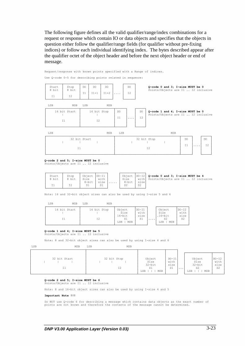
DNP V3.00 Application Layer (Version 0.03) 3-23
The following figure defines all the valid qualifier/range/index combinations for arequest or response which contain IO or data objects and specifies that the objects inquestion either follow the qualifier/range fields (for qualifier without pre-fixingindices) or follow each individual identifying index. The bytes described appear afterthe qualifier octet of the object header and before the next object header or end ofmessage.
Request/response with known points specified with a Range of indices.
Use Q-code 0-5 for describing points related in sequence:
┌─────────┬─────────┬────┬──────┬──────┐ ┌──────┐│ Start │ Stop │ DO │ DO │ DO │ │ DO │ Q-code 0 and 3; I-size MUST be 0│ 8 bit │ 8 bit │ │ │ │ │ │ Points/Objects are I1 .. I2 inclusive│ │ │ I1 │ I1+1 │ I1+2 │.... │ I2 ││ I1 │ I2 │ │ │ │ │ │└─────────┴─────────┴────┴──────┴──────┘ └──────┘
LSB MSB LSB MSB┌───────────────────┬───────────────────┬──────┐ ┌─────┐│ 16 bit Start │ 16 bit Stop │ DO │ │ DO │ Q-code 1 and 4; I-size MUST be 0│ | │ | │ │ │ │ Points/Objects are I1 .. I2 inclusive│ │ │ I1 │....│ I2 ││ I1 │ I2 │ │ │ ││ │ │ │ │ │└───────────────────┴───────────────────┴──────┘ └─────┘
LSB MSB LSB MSB┌───────────────────────────────────────┬─────────────────────────────────────┬──────┐ ┌─────┐│ 32 bit Start │ 32 bit Stop │ DO │ │ DO ││ | | | │ | | | │ │ │ ││ │ │ I1 │....│ I2 ││ I1 │ I2 │ │ │ ││ │ │ │ │ │└───────────────────────────────────────┴─────────────────────────────────────┴──────┘ └─────┘
Q-code 2 and 5; I-size MUST be 0Points/Objects are I1 .. I2 inclusive
┌─────────┬─────────┬────────┬──────┐ ┌────────┬─────┐│ Start │ Stop │ Object │DO-I1 │ │ Object │DO-I2│ Q-code 0 and 3; I-size MUST be 4│ 8 bit │ 8 bit │ Size │ with │ │ Size │ with│ Points/Objects are I1 .. I2 inclusive│ │ │ 8-bit │ size │..... │ 8-bit │ size││ I1 │ I2 │ S1 │ S1 │ │ S2 │ S2 │└─────────┴─────────┴────────┴──────┘ └────────┴─────┘
Note: 16 and 32-bit object sizes can also be used by using I-size 5 and 6
LSB MSB LSB MSB┌───────────────────┬───────────────────┬───────────┬──────┐ ┌───────────┬──────┐│ 16 bit Start │ 16 bit Stop │ Object │DO-I1 │ │ Object │DO-I2 ││ | │ | │ Size │ with │ │ Size │ with ││ │ │ 16-bit │ size │ │.16-bit │ size ││ I1 │ I2 │ S1 │ S1 │....│ S2 │ S2 ││ │ │ LSB | MSB │ │ │ LSB | MSB │ │└───────────────────┴───────────────────┴───────────┴──────┘ └───────────┴──────┘
Q-code 1 and 4; I-size MUST be 5Points/Objects are I1 .. I2 inclusive
Note: 8 and 32-bit object sizes can also be used by using I-size 4 and 6
LSB MSB LSB MSB┌───────────────────────────────┬─────────────────────────────┬───────────────┬──────┐│ │ │ │ │ ┌───────────────┬──────┐│ │ │ │ │ │ │ ││ 32 bit Start │ 32 bit Stop │ Object │ DO-I1│ │ Object │DO-I2 ││ | | | │ | | | │ Size │ with │ │ Size │ with ││ │ │ 32-bit │ size │ │ 32-bit │ size ││ I1 │ I2 │ S1 │ S1 │...│ S2 │ S2 ││ │ │ LSB | | | MSB │ │ │ LSB | | | MSB │ │└───────────────────────────────┴─────────────────────────────┴───────────────┴──────┘ └───────────────┴──────┘
Q-code 2 and 5; I-size MUST be 6Points/Objects are I1 .. I2 inclusive
Note: 8 and 16-bit object sizes can also be used by using I-size 4 and 5
Important Note !!!
Do NOT use Q-code 6 for describing a message which contains data objects as the exact number ofpoints are not known and therefore the contents of the message cannot be determined.
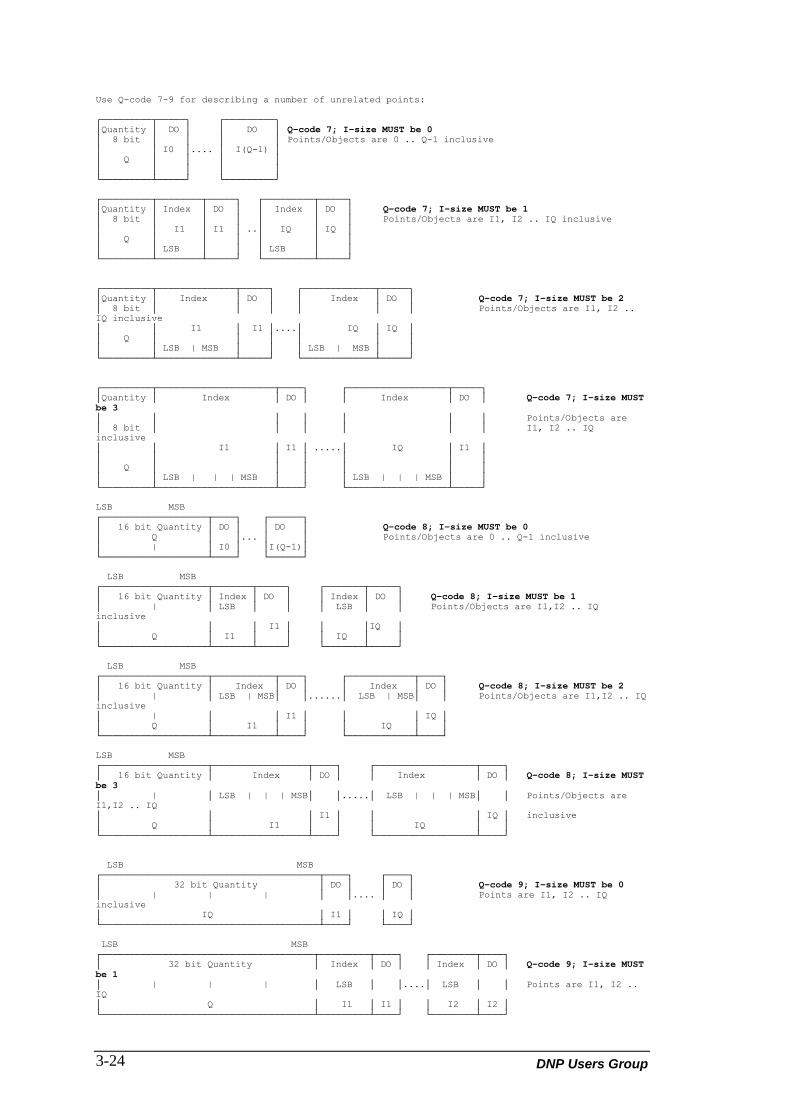
DNP Users Group3-24
Use Q-code 7-9 for describing a number of unrelated points:
┌─────────┬─────┐ ┌─────────┐│Quantity │ DO │ │ DO │ Q-code 7; I-size MUST be 0│ 8 bit │ │ │ │ Points/Objects are 0 .. Q-1 inclusive│ │ I0 │.... │ I(Q-1) ││ Q │ │ │ ││ │ │ │ │└─────────┴─────┘ └─────────┘
┌─────────┬────────┬─────┐ ┌─────────┬─────┐│Quantity │ Index │ DO │ │ Index │ DO │ Q-code 7; I-size MUST be 1│ 8 bit │ │ │ │ │ │ Points/Objects are I1, I2 .. IQ inclusive│ │ I1 │ I1 │ ..│ IQ │ IQ ││ Q │ │ │ │ │ ││ │ LSB │ │ │ LSB │ │└─────────┴────────┴─────┘ └─────────┴─────┘
┌─────────┬──────────────┬─────┐ ┌─────────────┬─────┐│Quantity │ Index │ DO │ │ Index │ DO │ Q-code 7; I-size MUST be 2│ 8 bit │ │ │ │ │ │ Points/Objects are I1, I2 ..IQ inclusive│ │ I1 │ I1 │....│ IQ │ IQ ││ Q │ │ │ │ │ ││ │ LSB | MSB │ │ │ LSB | MSB │ │└─────────┴──────────────┴─────┘ └─────────────┴─────┘
┌─────────┬─────────────────────┬────┐ ┌──────────────────┬─────┐│Quantity │ Index │ DO │ │ Index │ DO │ Q-code 7; I-size MUSTbe 3│ │ │ │ │ │ │ Points/Objects are│ 8 bit │ │ │ │ │ │ I1, I2 .. IQinclusive│ │ I1 │ I1 │ .....│ IQ │ I1 ││ │ │ │ │ │ ││ Q │ │ │ │ │ ││ │ LSB | | | MSB │ │ │ LSB | | | MSB │ │└─────────┴─────────────────────┴────┘ └──────────────────┴─────┘
LSB MSB┌───────────────────┬────┐ ┌──────┐│ 16 bit Quantity │ DO │ │ DO │ Q-code 8; I-size MUST be 0│ Q │ │... │ │ Points/Objects are 0 .. Q-1 inclusive│ | │ I0 │ │I(Q-1)│└───────────────────┴────┘ └──────┘
LSB MSB┌───────────────────┬───────┬─────┐ ┌───────┬─────┐│ 16 bit Quantity │ Index │ DO │ │ Index │ DO │ Q-code 8; I-size MUST be 1│ | │ LSB │ │ │ LSB │ │ Points/Objects are I1,I2 .. IQinclusive│ │ │ I1 │ │ │IQ ││ Q │ I1 │ │ │ IQ │ │└───────────────────┴───────┴─────┘ └───────┴─────┘
LSB MSB┌───────────────────┬───────────┬────┐ ┌────────────┬────┐│ 16 bit Quantity │ Index │ DO │ │ Index │ DO │ Q-code 8; I-size MUST be 2│ | │ LSB | MSB│ │......│ LSB | MSB│ │ Points/Objects are I1,I2 .. IQinclusive│ | │ │ I1 │ │ │ IQ ││ Q │ I1 │ │ │ IQ │ │└───────────────────┴───────────┴────┘ └────────────┴────┘
LSB MSB┌───────────────────┬─────────────────┬────┐ ┌──────────────────┬────┐│ 16 bit Quantity │ Index │ DO │ │ Index │ DO │ Q-code 8; I-size MUSTbe 3│ | │ LSB | | | MSB│ │.....│ LSB | | | MSB│ │ Points/Objects areI1,I2 .. IQ│ │ │ I1 │ │ │ IQ │ inclusive│ Q │ I1 │ │ │ IQ │ │└───────────────────┴─────────────────┴────┘ └──────────────────┴────┘
LSB MSB┌───────────────────────────────────────┬────┐ ┌────┐│ 32 bit Quantity │ DO │ │ DO │ Q-code 9; I-size MUST be 0│ | | | │ │.... │ │ Points are I1, I2 .. IQinclusive│ IQ │ I1 │ │ IQ │└───────────────────────────────────────┴────┘ └────┘
LSB MSB┌──────────────────────────────────────┬─────────┬────┐ ┌────────┬────┐│ 32 bit Quantity │ Index │ DO │ │ Index │ DO │ Q-code 9; I-size MUSTbe 1│ | | | │ LSB │ │....│ LSB │ │ Points are I1, I2 ..IQ│ Q │ I1 │ I1 │ │ I2 │ I2 │└──────────────────────────────────────┴─────────┴────┘ └────────┴────┘
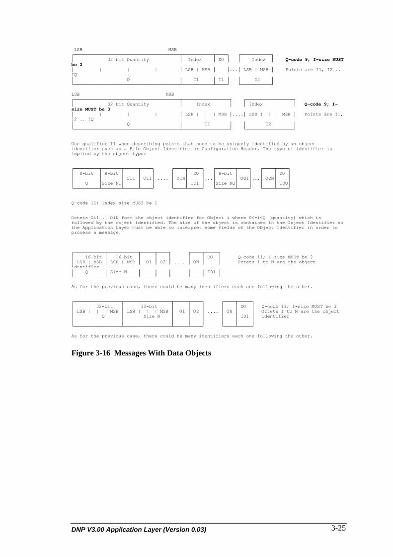
DNP V3.00 Application Layer (Version 0.03) 3-25
LSB MSB┌──────────────────────────────────────┬───────────┬────┐ ┌───────────┐│ 32 bit Quantity │ Index │ DO │ │ Index │ Q-code 9; I-size MUSTbe 2│ | | | │ LSB | MSB │ │...│ LSB | MSB │ Points are I1, I2 ..IQ│ Q │ I1 │ I1 │ │ I2 │└──────────────────────────────────────┴───────────┴────┘ └───────────┘
LSB MSB┌──────────────────────────────────────┬─────────────────┐ ┌─────────────────┐│ 32 bit Quantity │ Index │ │ Index │ Q-code 9; I-size MUST be 3│ | | | │ LSB | | | MSB │....│ LSB | | | MSB │ Points are I1,I2 .. IQ│ Q │ I1 │ │ I2 │└──────────────────────────────────────┴─────────────────┘ └─────────────────┘
Use qualifier 11 when describing points that need to be uniquely identified by an objectidentifier such as a File Object Identifier or Configuration Header. The type of identifier isimplied by the object type:
┌─────────┬───────┬─────┬────┐ ┌────┬─────┐ ┌───────┬────┐ ┌────┬────┐│ 8-bit │ 8-bit │ │ │ │ │ DO │ │ 8-bit │ │ │ │ DO ││ │ │ O11 │ O11│ .... │ O1N│ │...│ │ OQ1│...│ OQN│ ││ Q │Size N1│ │ │ │ │ ID1 │ │Size NQ│ │ │ │ IDQ│└─────────┴───────┴─────┴────┘ └────┴─────┘ └───────┴────┘ └────┴────┘
Q-code 11; Index size MUST be 1
Octets Oi1 .. OiN form the object identifier for Object i where 0<=i<Q (quantity) which isfollowed by the object identified. The size of the object is contained in the Object Identifier sothe Application Layer must be able to interpret some fields of the Object Identifier in order toprocess a message.
┌───────────┬───────────┬─────┬────┐ ┌────┬─────┐│ 16-bit │ 16-bit │ │ │ │ │ DO │ Q-code 11; I-size MUST be 2│ LSB | MSB │ LSB | MSB │ O1 │ O2 │ .... │ ON │ │ Octets 1 to N are the objectidentifier│ Q │ Size N │ │ │ │ │ ID1 │└───────────┴───────────┴─────┴────┘ └────┴─────┘
As for the previous case, there could be many identifiers each one following the other.
┌─────────────────┬─────────────────┬─────┬────┐ ┌────┬─────┐│ 32-bit │ 32-bit │ │ │ │ │ DO │ Q-code 11; I-size MUST be 3│ LSB | | | MSB │ LSB | | | MSB │ O1 │ O2 │ .... │ ON │ │ Octets 1 to N are the object│ Q │ Size N │ │ │ │ │ ID1 │ identifier│ │ │ │ │ │ │ │└─────────────────┴─────────────────┴─────┴────┘ └────┴─────┘
As for the previous case, there could be many identifiers each one following the other.
Figure 3-16 Messages With Data Objects

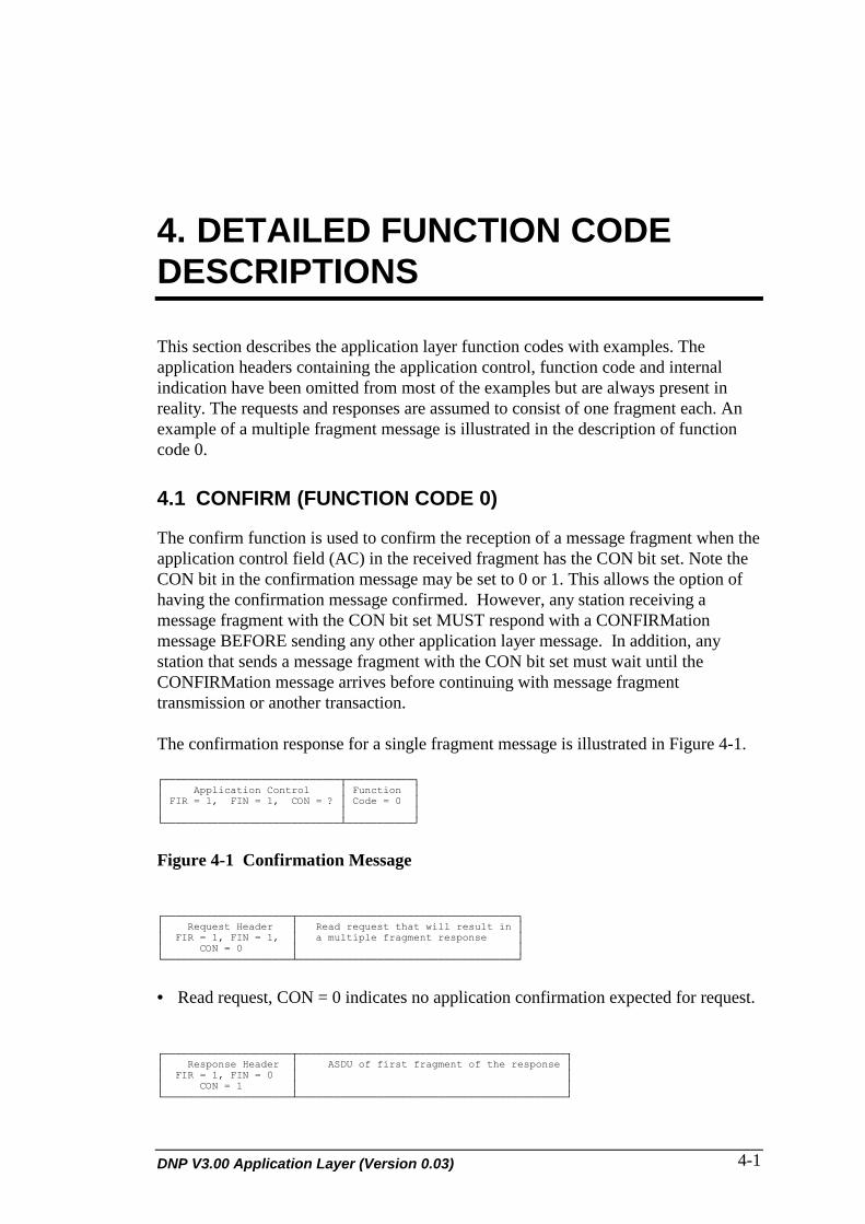
DNP V3.00 Application Layer (Version 0.03) 4-1
4. DETAILED FUNCTION CODEDESCRIPTIONS
This section describes the application layer function codes with examples. Theapplication headers containing the application control, function code and internalindication have been omitted from most of the examples but are always present inreality. The requests and responses are assumed to consist of one fragment each. Anexample of a multiple fragment message is illustrated in the description of functioncode 0.
4.1 CONFIRM (FUNCTION CODE 0)
The confirm function is used to confirm the reception of a message fragment when theapplication control field (AC) in the received fragment has the CON bit set. Note theCON bit in the confirmation message may be set to 0 or 1. This allows the option ofhaving the confirmation message confirmed. However, any station receiving amessage fragment with the CON bit set MUST respond with a CONFIRMationmessage BEFORE sending any other application layer message. In addition, anystation that sends a message fragment with the CON bit set must wait until theCONFIRMation message arrives before continuing with message fragmenttransmission or another transaction.
The confirmation response for a single fragment message is illustrated in Figure 4-1.
┌─────────────────────────────┬───────────┐│ Application Control │ Function ││ FIR = 1, FIN = 1, CON = ? │ Code = 0 ││ │ │└─────────────────────────────┴───────────┘
Figure 4-1 Confirmation Message
┌─────────────────────┬────────────────────────────────────┐│ Request Header │ Read request that will result in ││ FIR = 1, FIN = 1, │ a multiple fragment response ││ CON = 0 │ │└─────────────────────┴────────────────────────────────────┘
• Read request, CON = 0 indicates no application confirmation expected for request.
┌─────────────────────┬────────────────────────────────────────────┐│ Response Header │ ASDU of first fragment of the response ││ FIR = 1, FIN = 0 │ ││ CON = 1 │ │└─────────────────────┴────────────────────────────────────────────┘

DNP Users Group4-2
• First fragment of response. CON = 1 indicates the Outstation is expecting anapplication confirmation of the reception of this fragment.
┌─────────────────────────────┬───────────┐│ Request Header │ Function ││ FIR = 1, FIN = 1, CON = 0 │ Code = 0 ││ │ │└─────────────────────────────┴───────────┘
• Confirmation sent by the requesting station
┌─────────────────────┬────────────────────────────────────┐│ Response Header │ ASDU of second fragment ││ FIR = 0, FIN = 0 │ of response ││ CON = 1 │ │└─────────────────────┴────────────────────────────────────┘
• The second fragment of the response
┌───────────────────────────┬───────────┐│ Request Header │ Function ││ FIR = 1, FIN = 1, CON = 0 │ Code = 0 ││ │ │└───────────────────────────┴───────────┘
• Confirmation of the second fragment
┌─────────────────────┬───────────────────────────────────────────┐│ Response Header │ ASDU of last fragment of the response ││ FIR = 0, FIN = 1 │ ││ CON = 1 │ │└─────────────────────┴───────────────────────────────────────────┘
• The last fragment of the response
┌─────────────────────────────┬───────────┐│ Request Header │ Function ││ FIR = 1, FIN = 1, CON = 0 │ Code = 0 ││ │ │└─────────────────────────────┴───────────┘
• Confirmation of the last fragment of the response
4.2 READ (FUNCTION CODE 1)
The read function is the basic code used for requesting data objects from a Outstation.The object, qualifier and range field are coded in such a way that their size can becalculated allowing requests for multiple objects or ranges to be sent in a singlemessage. The number of multiple requests allowed in a single message is defined inthe device profile of each device DNP is implemented on.
The read request for a single range of objects is illustrated in Figure 4-2. Figure 4-3illustrates the request for 2 object types or possibly 2 ranges of the same object type.

DNP V3.00 Application Layer (Version 0.03) 4-3
┌─────────────────┬────────┬────────────┬────────┐│ Request Header │ Object │ Qualifier │ Range ││ AC │ FC = 1 │ │ │ ││ │ │ │ │ │└──────┴──────────┴────────┴────────────┴────────┘
Figure 4-2 Single Object Request
│ first Read request │ second Read request │┌─────────────────┼────────┬────────────┬────────┼────────┬───────────┬───────┤│ Request Header │ Object │ Qualifier │ Range │ Object │ Qualifier │ Range ││ AC | FC = 1 │ │ │ │ │ │ ││ │ │ │ │ │ │ │└─────────────────┴────────┴────────────┴────────┴────────┴───────────┴───────┘
Figure 4-3 Multiple Objects or Ranges
4.2.1 Read Requests
The following examples illustrate some legal qualifier and range combinations for theread function code.
octet 1 2 3 4 5┌──────┬────────┬─────────────────┬────────────┐│ │ │ Object gv │ Qualifier ││ AC │ FC = 1 │ g = n v = 0 │ 0000 0110 ││ │ │ | │ 0 6 │└──────┴────────┴─────────────────┴────────────┘
• Read object group n.• The qualifier code specifies all the defined objects of the group defined at the
Outstation. This qualifier code also indicates the range field is not present.• The index size has no meaning and is set to 0.• The Outstation may respond with any or all objects of the defined group. This
method is useful for requesting event data because the requesting station does notknow in advance which points have generated events.
octet 1 2 3 4 5 6 7┌──────┬────────┬─────────────────┬──────────────┬─────────────────┐│ │ │ Object gv │ Qualifier │ Range ││ AC │ FC = 1 │ g = n v = x │ 0000 | 0000 │ Start Stop ││ │ │ | │ 0 0 │ 7 | 9 │└──────┴────────┴─────────────────┴──────────────┴─────────────────┘
• Read object group n variation x.• The qualifier code specifies a range field with a 1 octet start and stop sub-field.• The range field specifies 3 objects starting at index 7 to index 9 inclusive.• The index size has no meaning and is set to 0.• The Outstation may respond within the range specified. This method is useful for
requesting specific data that is known to be valid at the time of the request.
octet 1 2 3 4 5 6 7 8 9┌──────┬────────┬─────────────────┬────────────┬─────────┬────────────────────┬────────┐│ │ │ object gv │ Qualifier │ Range │ ││ AC │ FC = 1 │ g = n v = x │ 0000 0001 │ Start │ Stop ││ │ │ | │ 0 1 │ 700 │ 702 │└──────┴────────┴─────────────────┴────────────┴───────────────────────────────────────┘
• Read object group n, variation x.

DNP Users Group4-4
• The qualifier code specifies a range field with a 2 octet start and stop sub-field.• The range field specifies 3 objects starting at index 700 to index 702 inclusive.• The index size has no meaning and is set to 0.• The Outstation may respond within the range specified. This method is useful for
requesting specific data that is known to be valid at the time of the request.
octet 1 2 3 4 5 6 7 8 9 10 11 12 13┌──────┬────────┬─────────────────┬────────────┬───────────────────────────────────────┐│ │ │ │ │ ││ │ │ Object gv │ Qualifier │ | | | Range | | | ││ AC │ FC = 1 │ g = n v = x │ 0000 0010 │ Start │ Stop ││ │ │ | │ 0 2 │ 70000 │ 70002 │└──────┴────────┴─────────────────┴────────────┴───────────────────────────────────────┘
• Read object group n, variation x.• The qualifier code specifies a range field with a 4 octet start and stop sub-field.• The range field specifies 3 objects starting at index 70000 to index 70002
inclusive.• The Index Size field has no meaning and is set to 0.• The Outstation may respond within the range specified. This method is useful for
requesting specific data that is known to be valid at the time of the request.
octet 1 2 3 4 5 6 7┌──────┬────────┬─────────────────┬────────────┬───────────────────┐│ │ │ Object gv │ Qualifier │ Range ││ AC │ FC = 1 │ g = n v = x │ 0000 0011 │ Start │ Stop ││ │ │ | │ 0 3 │ 7 │ 9 │└──────┴────────┴─────────────────┴────────────┴───────────────────┘
• Read object group n, variation x. In this case n and x would specify a generic octetobject
• The qualifier code specifies a range field with a 1 octet start and stop sub-field.• The range field specifies a starting virtual address of 7 and a virtual ending address
of 9.• The Index Size field has no meaning and is set to 0.• The Outstation may respond within the range specified. This method is useful for
requesting specific bytes from the memory of some remote application.
NOTE: Virtual addressing is normally used only for diagnostic ormanufacturing tests as intimate knowledge of the Outstation is neededto interpret the response.
octet 1 2 3 4 5 6 7 8 9┌──────┬────────┬─────────────────┬────────────┬───────────────────────────────────────┐│ │ │ Object gv │ Qualifier │ | Range | ││ AC │ FC = 1 │ g = n v = x │ 0000 0100 │ Start │ Stop ││ │ │ | │ 0 4 │ 700 │ 702 │└──────┴────────┴─────────────────┴────────────┴───────────────────────────────────────┘
• Read object group n, variation x. In this case n and x would specify a generic octetobject.
• The qualifier code specifies a range field with a 2 octet start and stop sub-field.• The range field specifies a starting virtual address of 700 and a virtual ending
address of 702.• The Index Size field has no meaning and is set to 0.
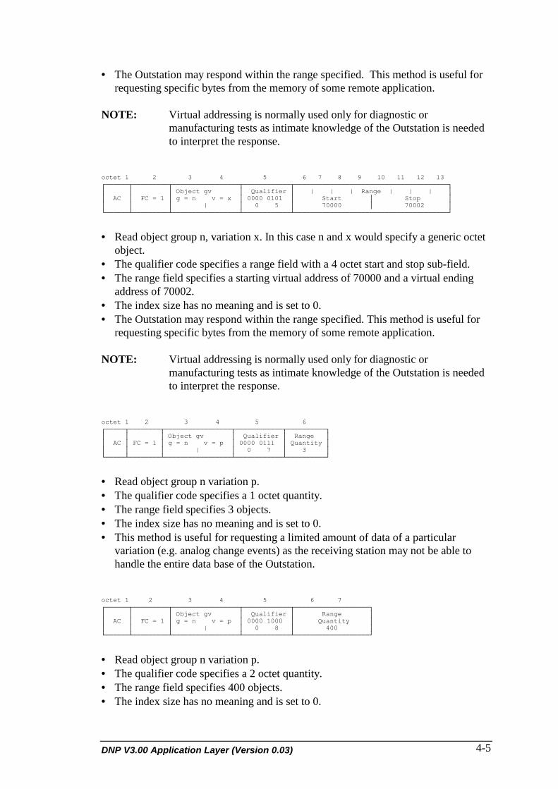
DNP V3.00 Application Layer (Version 0.03) 4-5
• The Outstation may respond within the range specified. This method is useful forrequesting specific bytes from the memory of some remote application.
NOTE: Virtual addressing is normally used only for diagnostic ormanufacturing tests as intimate knowledge of the Outstation is neededto interpret the response.
octet 1 2 3 4 5 6 7 8 9 10 11 12 13┌──────┬─────────┬─────────────────┬────────────┬───────────────────────────────────────┐│ │ │ Object gv │ Qualifier │ | | | Range | | | ││ AC │ FC = 1 │ g = n v = x │ 0000 0101 │ Start │ Stop ││ │ │ | │ 0 5 │ 70000 │ 70002 │└──────┴─────────┴─────────────────┴────────────┴───────────────────────────────────────┘
• Read object group n, variation x. In this case n and x would specify a generic octetobject.
• The qualifier code specifies a range field with a 4 octet start and stop sub-field.• The range field specifies a starting virtual address of 70000 and a virtual ending
address of 70002.• The index size has no meaning and is set to 0.• The Outstation may respond within the range specified. This method is useful for
requesting specific bytes from the memory of some remote application.
NOTE: Virtual addressing is normally used only for diagnostic ormanufacturing tests as intimate knowledge of the Outstation is neededto interpret the response.
octet 1 2 3 4 5 6┌─────┬────────┬─────────────────┬────────────┬──────────┐│ │ │ Object gv │ Qualifier │ Range ││ AC │ FC = 1 │ g = n v = p │ 0000 0111 │ Quantity ││ │ │ | │ 0 7 │ 3 │└─────┴────────┴─────────────────┴────────────┴──────────┘
• Read object group n variation p.• The qualifier code specifies a 1 octet quantity.• The range field specifies 3 objects.• The index size has no meaning and is set to 0.• This method is useful for requesting a limited amount of data of a particular
variation (e.g. analog change events) as the receiving station may not be able tohandle the entire data base of the Outstation.
octet 1 2 3 4 5 6 7┌──────┬─────────┬─────────────────┬────────────┬───────────────────┐│ │ │ Object gv │ Qualifier │ Range ││ AC │ FC = 1 │ g = n v = p │ 0000 1000 │ Quantity ││ │ │ | │ 0 8 │ 400 │└──────┴─────────┴─────────────────┴────────────┴───────────────────┘
• Read object group n variation p.• The qualifier code specifies a 2 octet quantity.• The range field specifies 400 objects.• The index size has no meaning and is set to 0.

DNP Users Group4-6
• This method is useful for requesting a limited amount of data of a particularvariation (e.g. binary input with time objects) as the receiving station may not beable to handle the entire data base (i.e. analog) of the Outstation.
octet 1 2 3 4 5 6 7 8 9┌──────┬─────────┬─────────────────┬────────────┬─────────────────────────────────────┐│ │ │ Object gv │ Qualifier │ Range ││ AC │ FC = 1 │ g = n v = p │ 0000 1001 │ Quantity ││ │ │ | │ 0 9 │ | 70000 | │└──────┴─────────┴─────────────────┴────────────┴─────────────────────────────────────┘
• Read object group n variation p.• The qualifier code specifies a 4 octet quantity.• The range field specifies 70000 objects.• The index size has no meaning and is set to 0.• This method is useful for requesting a limited amount of data of a particular
variation as the receiving station may not be able to handle the entire data base (i.e.analog) of the Outstation.
octet 1 2 3 4 5 6 7 8 9┌──────┬─────────┬─────────────────┬────────────┬──────────┬───────────────────────────┐│ │ │ Object gv │ Qualifier │ Range │ Indices ││ AC │ FC = 1 │ g = n v = x │ 0001 0111 │ Quantity │ 11 │ 22 │ 108 ││ │ │ │ 1 7 │ 3 │ │ │ │└──────┴─────────┴─────────────────┴────────────┴──────────┴───────────────────────────┘
• Read object group n, variation x.• The qualifier code specifies a list of objects in the index field.• The range field specifies that the list contains 3 entries.• The index size specifies each entry in the list is a 1 octet index.• This method is useful for requesting some specific points from the remote device.
For example, some critical status points may be requested for analysis or reportingpurposes.
NOTE: The range field is always the same size as an entry in the index list.This format would normally be used when the indices have valuesbetween 0 and 255.
octet 1 2 3 4 5 6 7 8 9 10 11 12 13┌──────┬────────┬─────────────────┬────────────┬────────────────────┬─────────────────────────────┐│ │ │ Object gv │ Qualifier │ Range │ Indices││ AC │ FC = 1 │ g = n v = x │ 0010 0111 │ Quantity │ 311 │ 422 │ 108││ │ │ | │ 2 7 │ 3 │ | │ | │ |│└──────┴────────┴─────────────────┴────────────┴────────────────────┴─────────────────────────────┘
• Read object group n, variation x.• The qualifier code specifies a list of objects in the index field.• The range field specifies the list contains 3 entries.• The index size specifies each entry in the list is a 2 octet index.• This method is useful for requesting some specific points from the remote device.
For example, some critical status points may be requested for analysis or reportingpurposes.

DNP V3.00 Application Layer (Version 0.03) 4-7
NOTE: The range field is always the same size as an entry in the index list.This format would normally be used when some or all of the indiceshave values greater than what will fit in 1 octet.
octet 1 2 3 4 5 6 7 8 9 18 19 20 21┌──────┬─────────┬─────────────────┬────────────┬────────────┬────────────────────────────────────┐│ │ │ Object gv │ Qualifier │ Range │ Indices││ AC │ FC = 1 │ g = n v = x │ 0011 0111 │ Quantity │ │ │││ │ │ | │ 3 7 │ 3 │ 70000 │ 76000 │ 90000│└──────┴─────────┴─────────────────┴────────────┴────────────┴────────────────────────────────────┘
• Read object group n, variation x.• The qualifier code specifies a list of objects in the index field.• The range field specifies the list contains 3 entries.• The index size specifies each entry in the list is a 4 octet index.• This method is useful for requesting some specific points from the remote device.
For example, some critical status points may be requested for analysis or reportingpurposes.
NOTE: The range field is always the same size as an entry in the index list.
octet 1 2 3 4 5 6 7 .....┌──────┬────────┬─────────────────┬────────────┬──────────┬──────────────────────────┐│ │ │ Object gv │ Qualifier │ Range │ Identifier ││ AC │ FC = 1 │ g = n v = v │ 0001 1011 │ Quantity │ ││ │ │ | │ 1 11 │ 1 │ Size | Object Identifier │└──────┴────────┴─────────────────┴────────────┴──────────┴──────┬───────────────────┤ │ Size octets │
• Read object group n variation v (in this case the group and variation identify theobject identifier).
• The qualifier code specifies a list of object identifiers in the identifier field and therange field is an 8 bit quantity. The size field is also an 8-bit quantity specifyingthat the object identifier is 'size' octets in length.
• The range field specifies the list contains 1 entry. The index size specifies that thequantity field and Size field are 8-bit in length.
• This method is useful for reading configurations from a remote device (if the FileObject Identifier is used). This method is however the only way in which torequest a data object that is larger than one fragment in size.
4.2.2 Read Responses
This section defines some of the legal forms of an object header prefixing the objectsin a response to a read request.
octet 1 2 3 4 5┌────────────────┬────────────┬───────────────────┐ ....│ Object gv │ Qualifier │ Range ││ group = n │ 0000 0000 │ Start │ Stop ││ variation = v │ 0 0 │ 7 │ 9 │└────────────────┴────────────┴─────────┴─────────┘ .....
• Objects following this header are group n, variation v.
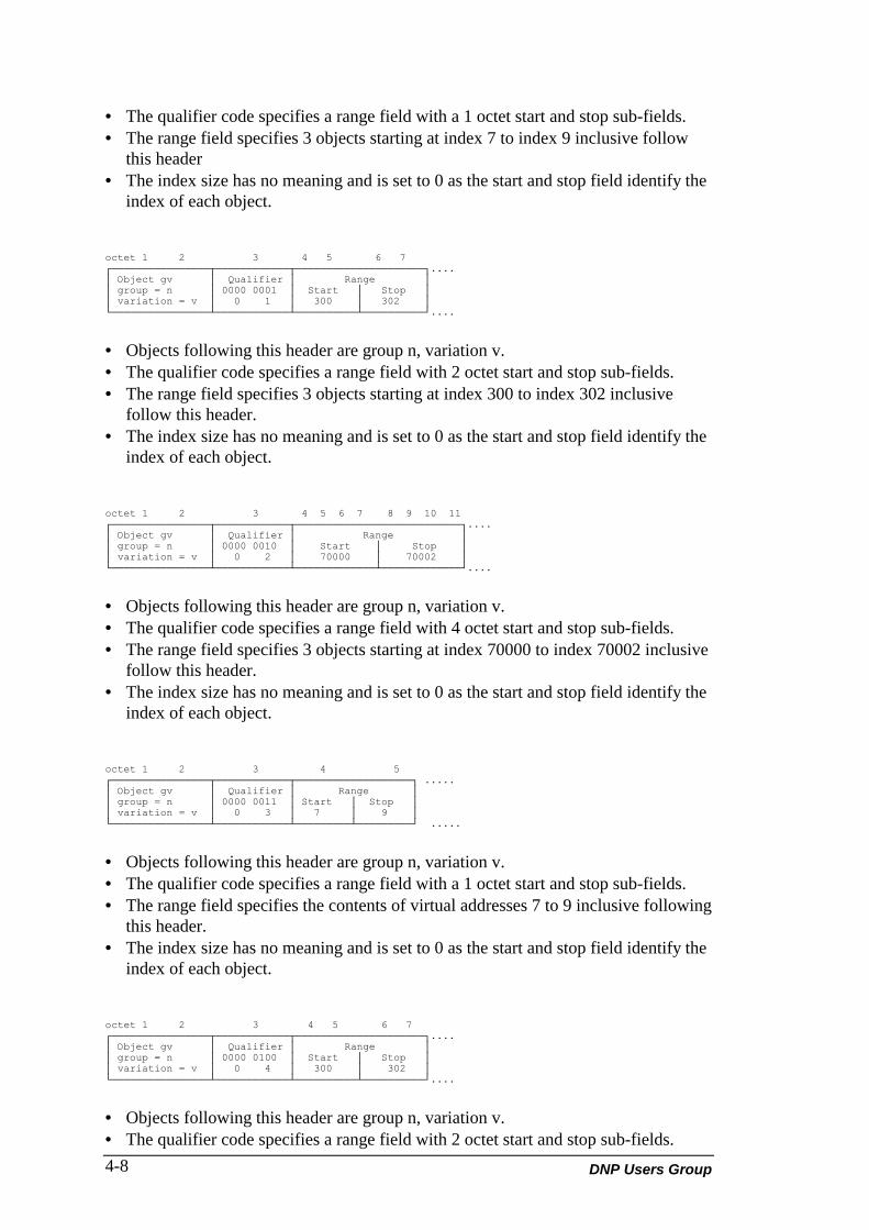
DNP Users Group4-8
• The qualifier code specifies a range field with a 1 octet start and stop sub-fields.• The range field specifies 3 objects starting at index 7 to index 9 inclusive follow
this header• The index size has no meaning and is set to 0 as the start and stop field identify the
index of each object.
octet 1 2 3 4 5 6 7┌────────────────┬────────────┬─────────────────────┐....│ Object gv │ Qualifier │ Range ││ group = n │ 0000 0001 │ Start │ Stop ││ variation = v │ 0 1 │ 300 │ 302 │└────────────────┴────────────┴──────────┴──────────┘....
• Objects following this header are group n, variation v.• The qualifier code specifies a range field with 2 octet start and stop sub-fields.• The range field specifies 3 objects starting at index 300 to index 302 inclusive
follow this header.• The index size has no meaning and is set to 0 as the start and stop field identify the
index of each object.
octet 1 2 3 4 5 6 7 8 9 10 11┌────────────────┬────────────┬───────────────────────────┐....│ Object gv │ Qualifier │ Range ││ group = n │ 0000 0010 │ Start │ Stop ││ variation = v │ 0 2 │ 70000 │ 70002 │└────────────────┴────────────┴─────────────┴─────────────┘....
• Objects following this header are group n, variation v.• The qualifier code specifies a range field with 4 octet start and stop sub-fields.• The range field specifies 3 objects starting at index 70000 to index 70002 inclusive
follow this header.• The index size has no meaning and is set to 0 as the start and stop field identify the
index of each object.
octet 1 2 3 4 5┌────────────────┬────────────┬───────────────────┐ .....│ Object gv │ Qualifier │ Range ││ group = n │ 0000 0011 │ Start │ Stop ││ variation = v │ 0 3 │ 7 │ 9 │└────────────────┴────────────┴─────────┴─────────┘ .....
• Objects following this header are group n, variation v.• The qualifier code specifies a range field with a 1 octet start and stop sub-fields.• The range field specifies the contents of virtual addresses 7 to 9 inclusive following
this header.• The index size has no meaning and is set to 0 as the start and stop field identify the
index of each object.
octet 1 2 3 4 5 6 7┌────────────────┬────────────┬─────────────────────┐....│ Object gv │ Qualifier │ Range ││ group = n │ 0000 0100 │ Start │ Stop ││ variation = v │ 0 4 │ 300 │ 302 │└────────────────┴────────────┴──────────┴──────────┘....
• Objects following this header are group n, variation v.• The qualifier code specifies a range field with 2 octet start and stop sub-fields.

DNP V3.00 Application Layer (Version 0.03) 4-9
• The range field specifies the contents of virtual addresses 300 to 302 inclusivefollowing this header.
• The index size has no meaning and is set to 0 as the start and stop field identify theindex of each object.
octet 1 2 3 4 5 6 7 8 9 10 11┌────────────────┬────────────┬───────────────────────────┐....│ Object gv │ Qualifier │ Range ││ group = n │ 0000 0101 │ Start │ Stop ││ variation = v │ 0 5 │ 70000 │ 70002 │└────────────────┴────────────┴─────────────┴─────────────┘....
• Objects following this header are group n, variation v.• The qualifier code specifies a range field with 4 octet start and stop sub-fields.• The range field specifies the contents of virtual addresses 70000 to 70002 inclusive
following this header.• The index size has no meaning and is set to 0 as the start and stop field identify the
index of each object.
octet 1 2 3 4┌────────────────┬────────────┬────────┐....│ Object gv │ Qualifier │ Range ││ group = n │ 0000 0111 │ 3 ││ variation = v │ 0 7 │ │└────────────────┴────────────┴────────┘....
• Objects following this header are group n, variation v.• The qualifier code specifies a range field with a 1 octet quantity.• The range field specifies 3 objects.• The index size specifies the objects are packed with no indices prefixing them.
This implies the first object in the message has an index of 0 and the last object inthis example will have an index of 2.
octet 1 2 3 4┌────────────────┬────────────┬────────┐....│ Object gv │ Qualifier │ Range ││ group = n │ 0001 0111 │ 3 ││ variation = v │ 1 7 │ │└────────────────┴────────────┴────────┘....
• Objects following this header are group n, variation v.• The qualifier code specifies a range field with a 1 octet quantity.• The range field specifies 3 objects.• The index size specifies the objects are prefixed with 1 octet index identifiers.
octet 1 2 3 4┌────────────────┬────────────┬────────┐....│ Object gv │ Qualifier │ Range ││ group = n │ 0010 0111 │ 3 ││ variation = v │ 2 7 │ │└────────────────┴────────────┴────────┘....
• Objects following this header are group n, variation v.• The qualifier code specifies a range field with a 1 octet quantity.• The range field specifies 3 objects.• The index size specifies the objects are prefixed with 2 octet index identifiers.
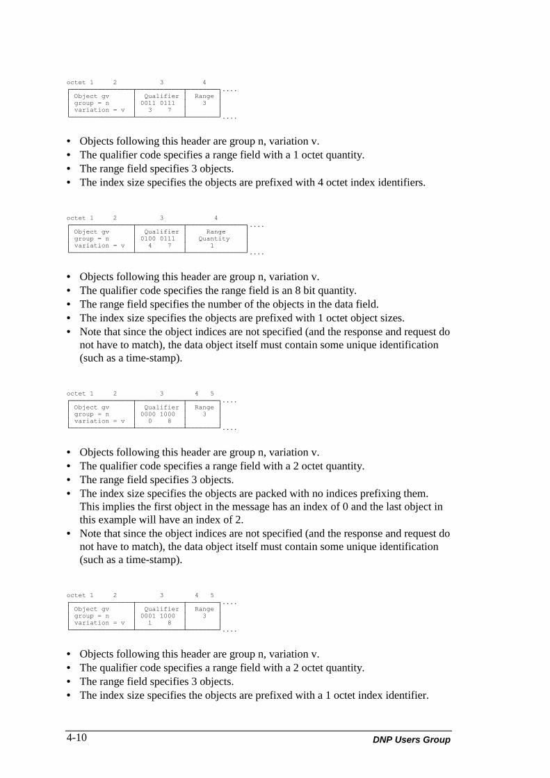
DNP Users Group4-10
octet 1 2 3 4┌────────────────┬────────────┬────────┐....│ Object gv │ Qualifier │ Range ││ group = n │ 0011 0111 │ 3 ││ variation = v │ 3 7 │ │└────────────────┴────────────┴────────┘....
• Objects following this header are group n, variation v.• The qualifier code specifies a range field with a 1 octet quantity.• The range field specifies 3 objects.• The index size specifies the objects are prefixed with 4 octet index identifiers.
octet 1 2 3 4┌────────────────┬────────────┬───────────────┐....│ Object gv │ Qualifier │ Range ││ group = n │ 0100 0111 │ Quantity ││ variation = v │ 4 7 │ 1 │└────────────────┴────────────┴───────────────┘....
• Objects following this header are group n, variation v.• The qualifier code specifies the range field is an 8 bit quantity.• The range field specifies the number of the objects in the data field.• The index size specifies the objects are prefixed with 1 octet object sizes.• Note that since the object indices are not specified (and the response and request do
not have to match), the data object itself must contain some unique identification(such as a time-stamp).
octet 1 2 3 4 5┌────────────────┬────────────┬────────┐....│ Object gv │ Qualifier │ Range ││ group = n │ 0000 1000 │ 3 ││ variation = v │ 0 8 │ │└────────────────┴────────────┴────────┘....
• Objects following this header are group n, variation v.• The qualifier code specifies a range field with a 2 octet quantity.• The range field specifies 3 objects.• The index size specifies the objects are packed with no indices prefixing them.
This implies the first object in the message has an index of 0 and the last object inthis example will have an index of 2.
• Note that since the object indices are not specified (and the response and request donot have to match), the data object itself must contain some unique identification(such as a time-stamp).
octet 1 2 3 4 5┌────────────────┬────────────┬────────┐....│ Object gv │ Qualifier │ Range ││ group = n │ 0001 1000 │ 3 ││ variation = v │ 1 8 │ │└────────────────┴────────────┴────────┘....
• Objects following this header are group n, variation v.• The qualifier code specifies a range field with a 2 octet quantity.• The range field specifies 3 objects.• The index size specifies the objects are prefixed with a 1 octet index identifier.

DNP V3.00 Application Layer (Version 0.03) 4-11
octet 1 2 3 4 5┌────────────────┬────────────┬────────┐....│ Object gv │ Qualifier │ Range ││ group = n │ 0010 1000 │ 300 ││ variation = v │ 2 8 │ │└────────────────┴────────────┴────────┘....
• Objects following this header are group n, variation v.• The qualifier code specifies a range field with a 2 octet quantity.• The range field specifies 300 objects.• The index size specifies the objects are prefixed with a 2 octet index identifier.
octet 1 2 3 4 5┌────────────────┬────────────┬────────┐....│ Object gv │ Qualifier │ Range ││ group = n │ 0011 1000 │ 300 ││ variation = v │ 3 8 │ │└────────────────┴────────────┴────────┘....
• Objects following this header are group n, variation v.• The qualifier code specifies a range field with a 2 octet quantity.• The range field specifies 300 objects.• The index size specifies the objects are prefixed with a 4 octet index identifier.
octet 1 2 3 4 5┌────────────────┬────────────┬───────────────┐....│ Object gv │ Qualifier │ Range ││ group = n │ 0101 1000 │ Quantity ││ variation = v │ 5 8 │ │└────────────────┴────────────┴───────────────┘....
• Objects following this header are group n, variation v.• The qualifier code specifies the range field is a 16 bit quantity.• The range field specifies the number of objects in the data field.• The index size specifies the objects are prefixed with 2 octet object sizes.• Note that since the object indices are not specified (and the response and request do
not have to match), the data object itself must contain some unique identification(such as a time-stamp).
octet 1 2 3 4 5 6 7┌────────────────┬────────────┬────────┐....│ Object gv │ Qualifier │ Range ││ group = n │ 0000 1001 │ 3 ││ variation = v │ 0 9 │ │└────────────────┴────────────┴────────┘....
• Objects following this header are group n, variation v.• The qualifier code specifies a range field with a 4 octet quantity.• The range field specifies 3 objects.• The index size specifies the objects are packed with no indices prefixing them.
This implies the first object in the message has an index of 0 and the last object inthis example will have an index of 2.
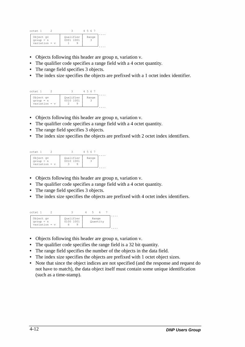
DNP Users Group4-12
octet 1 2 3 4 5 6 7┌────────────────┬────────────┬────────┐....│ Object gv │ Qualifier │ Range ││ group = n │ 0001 1001 │ 3 ││ variation = v │ 1 9 │ │└────────────────┴────────────┴────────┘....
• Objects following this header are group n, variation v.• The qualifier code specifies a range field with a 4 octet quantity.• The range field specifies 3 objects.• The index size specifies the objects are prefixed with a 1 octet index identifier.
octet 1 2 3 4 5 6 7┌────────────────┬────────────┬────────┐....│ Object gv │ Qualifier │ Range ││ group = n │ 0010 1001 │ 3 ││ variation = v │ 2 9 │ │└────────────────┴────────────┴────────┘....
• Objects following this header are group n, variation v.• The qualifier code specifies a range field with a 4 octet quantity.• The range field specifies 3 objects.• The index size specifies the objects are prefixed with 2 octet index identifiers.
octet 1 2 3 4 5 6 7┌────────────────┬────────────┬────────┐....│ Object gv │ Qualifier │ Range ││ group = n │ 0010 1001 │ 3 ││ variation = v │ 3 9 │ │└────────────────┴────────────┴────────┘....
• Objects following this header are group n, variation v.• The qualifier code specifies a range field with a 4 octet quantity.• The range field specifies 3 objects.• The index size specifies the objects are prefixed with 4 octet index identifiers.
octet 1 2 3 4 5 6 7┌────────────────┬────────────┬───────────────┐....│ Object gv │ Qualifier │ Range ││ group = n │ 0100 1001 │ Quantity ││ variation = v │ 4 9 │ │└────────────────┴────────────┴───────────────┘....
• Objects following this header are group n, variation v.• The qualifier code specifies the range field is a 32 bit quantity.• The range field specifies the number of the objects in the data field.• The index size specifies the objects are prefixed with 1 octet object sizes.• Note that since the object indices are not specified (and the response and request do
not have to match), the data object itself must contain some unique identification(such as a time-stamp).

DNP V3.00 Application Layer (Version 0.03) 4-13
The read response can also consist of a multi-fragment message with each objectidentifier specifying different portions (pages) of the entire object:
Fragment #1: FC=129, CON=? FIR=1 FIN=0
octet 1 2 3 4 5 6 7 .....┌─────────────────┬────────────┬──────────┬─────────────────────────────────────┬─────────┐│ Object gv │ Qualifier │ Range │ Identifier │ Data ││ g = n v = v │ 0001 1011 │ Quantity │ │ for ││ | │ 1 11 │ 1 │ Size │ Object Identifier for piece 1│ piece 1 │└─────────────────┴────────────┴──────────┴───────────────────────────────────────────────┘ Size octets
Fragment #2: FC=129, CON=? FIR=0 FIN=0
octet 1 2 3 4 5 6 7 .....┌─────────────────┬────────────┬──────────┬─────────────────────────────────────┬─────────┐│ Object gv │ Qualifier │ Range │ Identifier │ Data ││ g = n v = v │ 0001 1011 │ Quantity │ │ for ││ | │ 1 11 │ 1 │ Size │ Object Identifier for piece 2│ piece 2 │└─────────────────┴────────────┴──────────┴───────────────────────────────────────────────┘ Size octets
Fragment #3: FC=129, CON=? FIR=0 FIN=1
octet 1 2 3 4 5 6 7 .....┌─────────────────┬────────────┬──────────┬─────────────────────────────────────┬─────────┐│ Object gv │ Qualifier │ Range │ Identifier │ Data ││ g = n v = v │ 0001 1011 │ Quantity │ │ for ││ | │ 1 11 │ 1 │ Size │ Object Identifier for piece 3│ piece 3 │└─────────────────┴────────────┴──────────┴──────┴──────────────────────────────┼─────────┘ Size octets
• Read object group n variation v (in this case the group and variation identify theobject identifier).
• The qualifier code specifies a list of object identifiers in the identifier field and therange field is an 8 bit quantity. The size field is also an 8-bit quantity specifyingthat the object identifier plus data following the identifier is 'size' octets in length.
• The range field specifies the list contains 1 entry. The index size specifies that thequantity field and Size field are 8-bit in length.
• This method is useful for reading configurations from a remote device (if the FileIdentifier Object is used). This method is however the only way in which torequest a data object that is larger than one fragment in size.
• Note that each fragment is digestible by the requesting station because each objectidentifier specifies a unique portion of the object.
4.3 WRITE (FUNCTION CODE 2)
The write function code is used for moving objects from a master station to anOutstation. Figure 4-4 illustrates the general format of a message writing single objecttype or range. Figure 4-5 illustrates the writing of multiple objects or ranges. Theobject header is defined the same as in a read request. Figure 4-6 is an example of thewriting of a configuration to an Outstation. The response from the Outstation isalways a function code followed by the IIN. Typical uses of the Write function are todownload configuration or files to an Outstation and to set the time in the Outstation.
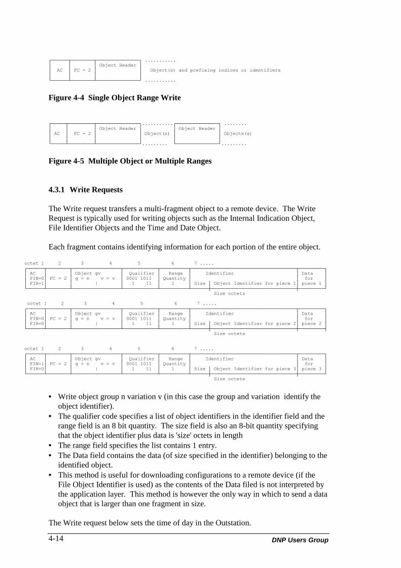
DNP Users Group4-14
┌──────┬────────┬───────────────┐ ...........│ │ │ Object Header ││ AC │ FC = 2 │ │ Object(s) and prefixing indices or identifiers│ │ │ │└──────┴────────┴───────────────┘ ...........
Figure 4-4 Single Object Range Write
┌─────┬─────────┬───────────────┐...........┌───────────────┐ ........│ │ │ Object Header │ │ Object Header ││ AC │ FC = 2 │ │ Object(s) │ │ Objects(s)│ │ │ │ │ │└─────┴─────────┴───────────────┘......... └───────────────┘.........
Figure 4-5 Multiple Object or Multiple Ranges
4.3.1 Write Requests
The Write request transfers a multi-fragment object to a remote device. The WriteRequest is typically used for writing objects such as the Internal Indication Object,File Identifier Objects and the Time and Date Object.
Each fragment contains identifying information for each portion of the entire object.
octet 1 2 3 4 5 6 7 .....┌──────┬────────┬─────────────────┬────────────┬──────────┬─────────────────────────────────────┬─────────┐│ AC │ │ Object gv │ Qualifier │ Range │ Identifier │ Data ││ FIN=0│ FC = 2 │ g = n v = v │ 0001 1011 │ Quantity │ │ for ││ FIR=1│ │ | │ 1 11 │ 1 │ Size │ Object Identifier for piece 1│ piece 1 │└──────┴────────┴─────────────────┴────────────┴──────────┴──────┼──────────────────────────────┼─────────┘ Size octets
octet 1 2 3 4 5 6 7 .....┌──────┬────────┬─────────────────┬────────────┬──────────┬─────────────────────────────────────┬─────────┐│ AC │ │ Object gv │ Qualifier │ Range │ Identifier │ Data ││ FIN=0│ FC = 2 │ g = n v = v │ 0001 1011 │ Quantity │ │ for ││ FIR=0│ │ | │ 1 11 │ 1 │ Size │ Object Identifier for piece 2│ piece 2 │└──────┴────────┴─────────────────┴────────────┴──────────┴──────┼──────────────────────────────┼─────────┤ Size octets
octet 1 2 3 4 5 6 7 .....┌──────┬────────┬─────────────────┬────────────┬──────────┬─────────────────────────────────────┬─────────┐│ AC │ │ Object gv │ Qualifier │ Range │ Identifier │ Data ││ FIN=1│ FC = 2 │ g = n v = v │ 0001 1011 │ Quantity │ │ for ││ FIR=0│ │ | │ 1 11 │ 1 │ Size │ Object Identifier for piece 3│ piece 3 │└──────┴────────┴─────────────────┴────────────┴──────────┴──────┼──────────────────────────────┼─────────┘ Size octets
• Write object group n variation v (in this case the group and variation identify theobject identifier).
• The qualifier code specifies a list of object identifiers in the identifier field and therange field is an 8 bit quantity. The size field is also an 8-bit quantity specifyingthat the object identifier plus data is 'size' octets in length
• The range field specifies the list contains 1 entry.• The Data field contains the data (of size specified in the identifier) belonging to the
identified object.• This method is useful for downloading configurations to a remote device (if the
File Object Identifier is used) as the contents of the Data filed is not interpreted bythe application layer. This method is however the only way in which to send a dataobject that is larger than one fragment in size.
The Write request below sets the time of day in the Outstation.

DNP V3.00 Application Layer (Version 0.03) 4-15
octet 1 2 3 4 5 6 7 .....┌──────┬────────┬─────────────────┬────────────┬──────────┬─────────────┐│ AC │ │ Object gv │ Qualifier │ Range │ Time Object ││ FIN=1│ FC = 2 │ g = n v = v │ 0000 0000 │ Quantity │ ││ FIR=1│ │ | │ 0 00 │ 1 │ │└──────┴────────┴─────────────────┴────────────┴──────────┴─────────────┘
• The qualifier specifies a 1 octet quantity; the quantity field specifies 1 object andthe Object field identifies the object as a Time and Date Object.
4.3.2 Write Responses
The response to a Write request can only consist of the IIN (Internal Indications) thatindicates the success of the Write operation and so there is no ASDU portion of aWrite response. The response always uses the Response function code.
4.4 SELECT (FUNCTION CODE 3)
The select function code is used to select one or more control points at an Outstation.These may be control relay outputs, analog outputs or pattern control blocks. Thisfunction does not output or activate the new state or value but makes them ready(arms them) and reports their status. An additional operate message must be sent tothe Outstation to actually activate the request. The operate message control objectsmust match the control objects in the preceding select message before the activationtakes place. The select message causes the Outstation to starts a timer. The operatemessage must be received correctly before the timer expires in order for the activationto take place.
There are two forms to the control messages. The first form is for control blocks witha fixed size and the second form is for a control block of variable size. The variablesized control block is for pattern outputs.
Figure 4-6 illustrates a select message (fixed size control blocks) sent from a masterstation to an Outstation.
The Outstation responds to a select message by arming the specified points (specifiedby the index preceding the control blocks) and returning the request in the response asillustrated in Figure 4-7 (fixed size control blocks). The response is identical to therequest except that it includes the IIN and modified status bytes (part of the controlblock objects). The status bytes state the success or failure of the Select request.
┌──────┬─────────┬───────────────┬───────────┬──────────┬───────┬─────────┬───────┬─────────┐│ │ │ Object gv │ Qualifier │ Range │ │ control │ │ control ││ AC │ FC = 3 │ group = n │ 0001 0111 │ Quantity │ index │ block │ index │ block ││ │ │ variation = v │ 1 7 │ 2 │ │ object 1│ │ object 2│└──────┴─────────┴───────────────┴───────────┴──────────┴───────┴─────────┴───────┴─────────┘
Figure 4-6 Master Selection of Two Control or Analog Outputs
• Object following this header is group n (must be a control block object relating tooutputs or setpoints), variation v.
• The qualifier code specifies a range field with a 1 octet quantity of control blocks.• The index size specifies 1 octet indices prefixing each control block.

DNP Users Group4-16
┌────┬────┬──────┬───────────────┬───────────┬──────────┬───────┬─────────┬───────┬─────────┐│ │ │ │ Object gv │ Qualifier │ Range │ │ control │ │ control ││ AC │ FC │ IIN │ group = n │ 0001 0111 │ Quantity │ index │ block │ index │ block ││ │ │ │ variation = v │ 1 7 │ │ │ object 1│ │ object 2│└────┴────┴──────┴───────────────┴───────────┴──────────┴───────┴─────────┴───────┴─────────┘
Figure 4-7 Outstation Response
The Outstation response control objects must match the control objects (byte for byte)in the request or the operate message will not be sent.
4.4.1 Pattern Control
Figure 4-8 illustrates a master station select message for a pattern andFigure 4-9 an Outstation response.
┌────┬────────┬───────────────┬────────────┬────────┬──────────┐│ │ │ Object gv │ Qualifier │Quantity│ pattern ││ AC │ FC = 3 │ group = a │ 0000 0111 │ │ control ││ │ │ variation = b │ 0 7 │ 1 │ block │... (continued)└────┴────────┴───────────────┴────────────┴────────┴──────────┘
┌────────────────┬───────────┬──────────────┬────────┬────────┬────────┬────────┐│ Object gv │ Qualifier │ Range │pattern │pattern │pattern │pattern ││ group = c │0000 0000 │ Start | Stop │ mask │ mask │ mask │ mask ││ variation = d │ 0 0 │ 5 8 │object 5│object 6│object 7│object 8│└────────────────┴───────────┴──────────────┴────────┴────────┴────────┴────────┘
Figure 4-8 Master Selection of a Pattern Output
• The first object, Object a, Variation b, specified is a Pattern Control Block whichdescribes all the parameters that are common to the control points specified in thePattern Mask Objects. Following this object are a number of Pattern Mask objects,Object c, Variation d, which describe whether or not the point should be activated.
• The first qualifier code specifies a 8-bit range (quantity) field which specifies one(1) Pattern Control Block.
• The second qualifier code specifies a range field with a 1 octet start and stop sub-field. This range specifies the Pattern Mask Objects which are to be considered forthe pattern control.
• The above message constitutes one pattern control request. Multiple requests(Pattern Control Block followed by multiple Pattern Mask Objects) can be sent inone message as long as the total size of the requests can fit into one applicationlayer fragment.
┌────┬────────┬───────────────┬────────────┬────────┬──────────┐│ │ │ Object gv │ Qualifier │Quantity│ pattern ││ AC │ FC=128 │ group = a │ 0000 0111 │ │ control ││ │ │ variation = b │ 0 7 │ 1 │ block │... (continued)└────┴────────┴───────────────┴────────────┴────────┴──────────┘
┌────────────────┬───────────┬──────────────┬────────┬────────┬────────┬────────┐│ Object gv │ Qualifier │ Range │pattern │pattern │pattern │pattern ││ group = c │0000 0000 │ Start | Stop │ mask │ mask │ mask │ mask ││ variation = d │ 0 0 │ 5 8 │object 5│object 6│object 7│object 8│└────────────────┴───────────┴──────────────┴────────┴────────┴────────┴────────┘
Figure 4-9 Outstation Response to the Pattern Select Message
• Notice that the format of the response is identical to the request message (exceptthe application response header). The objects returned will be used by the masterto verify the success of the select operation.

DNP V3.00 Application Layer (Version 0.03) 4-17
4.5 OPERATE (FUNCTION CODE 4)
The operate function code is used to activate one or more control or analog outputs atan Outstation. A matching message using the select function code must previouslyhave been received, and the arm timer must still be active before the activation willtake place. The format of this message is the same as a select message except thefunction code is 4.
┌────┬────────┬───────────────┬────────────┬─────────────┬──────────┬───────────┐│ │ │ Object gv │ Qualifier │ Range │ control │ control ││ AC │ FC = 4 │ group = n │ 0000 0111 │ Quantity │ block 1 │ block 2 ││ │ │ variation = v │ 0 7 │ 2 │ │ │└────┴────────┴───────────────┴────────────┴─────────────┴──────────┴───────────┘
Figure 4-10 Master Selection of Two Outputs or Setpoints
• Object following this header is group n (must be a control block object relating tooutputs or setpoints), variation v.
• The qualifier code specifies a range field with a 1 octet quantity of control blocks.
┌────┬────┬──────┬───────────────┬────────────┬──────────┬─────────┬─────────┐│ │ │ │ Object gv │ Qualifier │ Range │ control │ control ││ AC │ FC │ IIN │ group = n │ 0000 0111 │ Quantity │ block 1 │ block 2 ││ │ │ │ variation = v │ 0 7 │ 2 │ │ │└────┴────┴──────┴───────────────┴────────────┴──────────┴─────────┴─────────┘
Figure 4-11 Outstation Response
• Object following this header is group n (must be a control block object relating tooutputs or setpoints), variation v.
• The qualifier code specifies a range field with a 1 octet quantity of control blocks.• Indication of the success or failure of the operations is returned in the Output Status
bytes, one of which is built into each of the control block objects. In the case of aPattern Mask object, the status is part of the Pattern Control Block object precedingthe mask.
4.6 DIRECT OPERATE (FUNCTION CODE 5)
The direct operate function code is used to activate one or more outputs or setpoints atan Outstation. A preceding select message is not required. The format of this messageis the same as a select or operate message except the function code is 5.
┌────┬────────┬───────────────┬────────────┬─────────────┬──────────┬───────────┐│ │ │ Object gv │ Qualifier │ Range │ control │ control ││ AC │ FC = 5 │ group = n │ 0000 0111 │ Quantity │ block 1 │ block 2 ││ │ │ variation = v │ 0 7 │ 2 │ │ │└────┴────────┴───────────────┴────────────┴─────────────┴──────────┴───────────┘
Figure 4-12 Master Selection of Two Outputs or Setpoints
• Object following this header is group n (must be a control block object relating tooutputs or setpoints), variation v.
• The qualifier code specifies a range field with a 1 octet quantity of control blocks.

DNP Users Group4-18
┌────┬────┬─────┬───────────────┬────────────┬──────────┬─────────┬─────────┐│ │ │ │ Object gv │ Qualifier │ Range │ control │ control ││ AC │ FC │ IIN │ group = n │ 0000 0111 │ Quantity │ block 1 │ block 2 ││ │ │ │ variation = v │ 0 7 │ 2 │ │ │└────┴────┴─────┴───────────────┴────────────┴──────────┴─────────┴─────────┘
Figure 4-13 Outstation Response
• Object following this header is group n (must be a control block object relating tooutputs or setpoints), variation v.
• The qualifier code specifies a range field with a 1 octet quantity of control blocks.
4.7 DIRECT OPERATE - NO ACKNOWLEDGEMENT(FUNCTION CODE 6)
The direct operate No Acknowledgement function code is used to activate one ormore outputs or setpoints at a Outstation. A preceding select message is not required.The format of this message is the same as a select or operate message except thefunction code is 6 and the Outstation does not respond with a message to the masterstation.
┌────┬────────┬───────────────┬────────────┬─────────────┬──────────┬───────────┐│ │ │ Object gv │ Qualifier │ Range │ control │ control ││ AC │ FC = 6 │ group = n │ 0000 0111 │ Quantity │ block 1 │ block 2 ││ │ │ variation = v │ 0 7 │ 2 │ │ │└────┴────────┴───────────────┴────────────┴─────────────┴──────────┴───────────┘
Figure 4-14 Master Selection of Two Outputs or Setpoints
• Object following this header is group n (must be a control block object relating tooutputs or setpoints), variation v.
• The qualifier code specifies a range field with a 1 octet quantity of control blocks.
4.8 IMMEDIATE FREEZE (FUNCTION CODE 7)
This function code is used to copy the specified data objects to a freeze buffer. Uponreception of the message, the Outstation should copy the current values of thespecified data objects to their appropriate freeze buffers. The objects which werefrozen can be requested (in another request) by asking for frozen objects.
┌────┬────────┬───────────────┐ ┌───────────────┐│ │ │ Object Header │ │ Object Header ││ AC │ FC = 7 │ │...│ ││ │ │ │ │ │└────┴────────┴───────────────┘ └───────────────┘
Figure 4-15 Master Immediate Freeze Control Message
The request can contain multiple object headers which specify many objects to freeze.Typically, however, only counter objects are frozen.
┌────┬─────┬───────────┐│ │ │ ││ AC │ FC │ IIN ││ │ │ │└────┴─────┴───────────┘
Figure 4-16 Outstation Response to Immediate Freeze

DNP V3.00 Application Layer (Version 0.03) 4-19
The Outstation response can indicate (in the IIN) that the objects in the request are notknown.
4.9 IMMEDIATE FREEZE - NO ACKNOWLEDGEMENT(FUNCTION CODE 8)
This function code works identically to the previous function code (Immediate Freeze)except that no Outstation response is needed. Typically, this function code is used toperform a global freeze on all Outstations belonging to the master. In this case, theSEND-NO REPLY services of the Data Link Layer may have to be used in certainenvironments.
┌────┬────────┬───────────────┐ ┌───────────────┐│ │ │ Object Header │ │ Object Header ││ AC │ FC = 8 │ │...│ ││ │ │ │ │ │└────┴────────┴───────────────┘ └───────────────┘
Figure 4-17 Master Immediate Freeze No-Ack Control Message
4.10 FREEZE AND CLEAR (FUNCTION CODE 9)
This function code is used to copy the specified data to a freeze buffer like the freezeimmediate function code but then the Outstation clears ( to 0 ) the specified dataobjects. Typically, this function code is used to freeze counters or accumulators andthen reset them to 0.
┌────┬────────┬───────────────┐ ┌───────────────┐│ │ │ Object Header │ │ Object Header ││ AC │ FC = 9 │ │...│ ││ │ │ │ │ │└────┴────────┴───────────────┘ └───────────────┘
Figure 4-18 Master Freeze and Clear Control Message
┌────┬─────┬───────────┐│ │ │ ││ AC │ FC │ IIN ││ │ │ │└────┴─────┴───────────┘
Figure 4-19 Outstation Response to Freeze and Clear Request
4.11 FREEZE AND CLEAR - NO ACKNOWLEDGEMENT(FUNCTION CODE 10)
This function code works identically to the previous function code (Freeze and Clear)except that no Outstation response is needed. Typically, this function code is used toperform a global freeze and clear on all Outstations belonging to the master.

DNP Users Group4-20
┌────┬────────┬───────────────┐ ┌───────────────┐│ │ │ Object Header │ │ Object Header ││ AC │ FC= 10 │ │...│ ││ │ │ │ │ │└────┴────────┴───────────────┘ └───────────────┘
Figure 4-20 Master Freeze and Clear No-Ack Control Message
4.12 FREEZE WITH TIME (FUNCTION CODE 11)
This function code initiates the periodic freezing of the specified data objects. TheTime and Date with Interval object sent preceding the objects to freeze is described inthe table below. As shown, the object has two components: a time field (absolute) andan interval time field. The value of these fields determines the behaviour of theOutstation freezing.
TIME INTERVAL DESCRIPTIONnon zero zero Freeze once at specified time.zero zero Freeze Immediately.zero non zero Freezing is synchronized to the
beginning of the current hour. The firstfreeze will occur at the smallestmultiple greater than or equal to thecurrent time. Subsequent freezes willoccur at each interval increment.
non zero non zero Start freezing at the specified time andrepeat at each interval incrementthereafter
┌────┬─────────┬─────────────────┬───────────────────────────┬───────────────────┐│ │ │ Object Header │ Time Object │ Object Header(s) ││ AC │ FC = 11 │ for time object │ Time and Date │ Interval │ for data objects ││ │ │ │ │ │ to freeze │└────┴─────────┴─────────────────┴───────────────┴───────────┴───────────────────┘
Figure 4-21 Master Freeze With Time Message
┌────┬─────┬───────────┐│ │ │ ││ AC │ FC │ IIN ││ │ │ │└────┴─────┴───────────┘
Figure 4-22 Outstation Response to Freeze With Time
The time object must contain the time and interval. These objects are defined in theDNP Data Object Library (P009-0BL).
Example: A time object specifies the time of day as 2:32 pm and an interval of 10minutes. The first freeze will occur at 2:32 pm and subsequent freezes every 10minutes starting from 2:42 pm.

DNP V3.00 Application Layer (Version 0.03) 4-21
4.13 FREEZE WITH TIME - NO ACKNOWLEDGEMENT(FUNCTION CODE 12)
This function code works identically to the previous function code (Freeze WithTime) except that no Outstation response is needed. Typically, this function code isused to perform a global freeze with time on all Outstations belonging to the master.In this case, the SEND-NO REPLY services of the Data Link Layer may have to beused in certain environments.
┌────┬─────────┬─────────────────┬───────────────────────────┬───────────────────┐│ │ │ Object Header │ Time Object │ Object Header(s) ││ AC │ FC = 12 │ for time object │ Time and Date │ Interval │ for data objects ││ │ │ │ │ │ to freeze │└────┴─────────┴─────────────────┴───────────────┴───────────┴───────────────────┘
Figure 4-23 Master Freeze With Time No-Ack Message
4.14 COLD RESTART (FUNCTION CODE 13)The cold restart functioncode makes the Outstation perform a complete restart of the user application , as if ithas been newly powered up.
┌────┬────────┐│ │ ││ AC │ FC = 13││ │ │└────┴────────┘
Figure 4-24 Master Cold Restart Control Message
┌────┬─────┬───────────┬───────────┬───────────────┐│ │ │ │ Object │ Time Delay ││ AC │ FC │ IIN │ Header │ Object ││ │ │ │ for time │ │└────┴─────┴───────────┴───────────┴───────────────┘
Figure 4-25 Outstation Response to Cold Restart Request
The Outstation, upon receiving the Cold Restart request will response with a TimeDelay Object (Time Delay Fine or Time Delay Course) which specifies a time intervaluntil the Outstation will be ready for further communications. The master should notattempt to communicate with the Outstation until the interval has elapsed. Theinterval allows the Outstation to perform a restart sequence and enable DNPcommunications again. After the response is sent (and transaction was successful) theOutstation should perform the restart procedure. The Time Delay Fine object isdefined in the DNP Data Object Library (P009-0BL).
4.15 WARM RESTART (FUNCTION CODE 14)
This code restart function code specifies that the Outstation perform a restart, but it isnot necessary to run through the entire reset sequence (only certain applications needbe restarted). The DNP application may reset itself without resetting other subsystemsor processes. Typically this function makes an Outstation application initialize itsconfiguration and clear events stored in its local buffers.

DNP Users Group4-22
┌────┬─────────┐│ │ ││ AC │ FC = 14 ││ │ │└────┴─────────┘
Figure 4-26 Master Warm Restart Control Message
┌────┬─────┬───────────┬───────────┬──────────────┐│ │ │ │ Object │ Time Delay ││ AC │ FC │ IIN │ Header │ Object ││ │ │ │ for time │ │└────┴─────┴───────────┴───────────┴──────────────┘
Figure 4-27 Outstation Response to Warm Restart Request
The Outstation response is identical to the response to the Cold Restart function codeand should be interpreted in the same way. The Time Delay Object is actually a TimeDelay Fine or Time Delay Course object.
4.16 INITIALIZE DATA (FUNCTION CODE 15)
This function code specifies that configurable data is to be set to the initial or defaultsettings. For example, this function could be used to clear counters. Note that theinitial settings are NOT contained in the request.
┌────┬─────────┬──────────────────┐│ │ │ Object Header ││ AC │ FC = 15 │ for data objects ││ │ │ to initialize │└────┴─────────┴──────────────────┘
Figure 4-28 Master Initialize Data Control Message
┌────┬─────┬───────────┐│ │ │ ││ AC │ FC │ IIN ││ │ │ │└────┴─────┴───────────┘
Figure 4-29 Outstation Response to Initialize Data Request
The response only indicates the success or failure of the requested operation.
4.17 INITIALIZE APPLICATION (FUNCTION CODE 16)
This function code initializes the specified applications at the Outstation inpreparation for execution.
octet 1 2 3 4 5 6 7...┌────┬─────────┬───────────────┬───────────┬─────────────┬─────────────┬─────────────┐│ │ │ Object gv │ Qualifier │ Range │ Application │Application ││ AC │ FC = 16 │ Group = n │ 0001 1011 │ Quantity │ Identifier │Object ││ │ │ Variation = v │ 1 11 │ 1 │ Size │Identifier │└────┴─────────┴───────────────┴───────────┴─────────────┴─────────────┴─────────────┘
Figure 4-30 Master Initialize Application Control Message
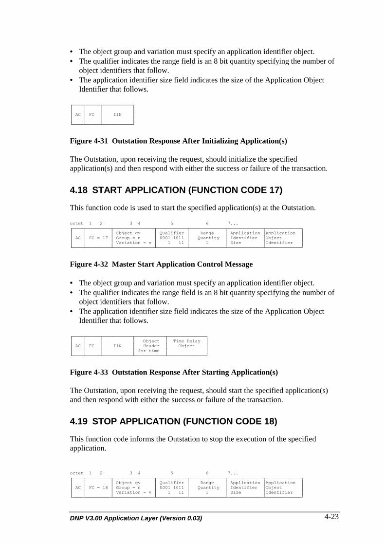
DNP V3.00 Application Layer (Version 0.03) 4-23
• The object group and variation must specify an application identifier object.• The qualifier indicates the range field is an 8 bit quantity specifying the number of
object identifiers that follow.• The application identifier size field indicates the size of the Application Object
Identifier that follows.
┌────┬─────┬───────────┐│ │ │ ││ AC │ FC │ IIN ││ │ │ │└────┴─────┴───────────┘
Figure 4-31 Outstation Response After Initializing Application(s)
The Outstation, upon receiving the request, should initialize the specifiedapplication(s) and then respond with either the success or failure of the transaction.
4.18 START APPLICATION (FUNCTION CODE 17)
This function code is used to start the specified application(s) at the Outstation.
octet 1 2 3 4 5 6 7...┌────┬─────────┬───────────────┬───────────┬─────────────┬─────────────┬─────────────┐│ │ │ Object gv │ Qualifier │ Range │ Application │Application ││ AC │ FC = 17 │ Group = n │ 0001 1011 │ Quantity │ Identifier │Object ││ │ │ Variation = v │ 1 11 │ 1 │ Size │Identifier │└────┴─────────┴───────────────┴───────────┴─────────────┴─────────────┴─────────────┘
Figure 4-32 Master Start Application Control Message
• The object group and variation must specify an application identifier object.• The qualifier indicates the range field is an 8 bit quantity specifying the number of
object identifiers that follow.• The application identifier size field indicates the size of the Application Object
Identifier that follows.
┌────┬─────┬───────────┬───────────┬──────────────┐│ │ │ │ Object │ Time Delay ││ AC │ FC │ IIN │ Header │ Object ││ │ │ │ for time │ │└────┴─────┴───────────┴───────────┴──────────────┘
Figure 4-33 Outstation Response After Starting Application(s)
The Outstation, upon receiving the request, should start the specified application(s)and then respond with either the success or failure of the transaction.
4.19 STOP APPLICATION (FUNCTION CODE 18)
This function code informs the Outstation to stop the execution of the specifiedapplication.
octet 1 2 3 4 5 6 7...┌────┬─────────┬───────────────┬───────────┬─────────────┬─────────────┬─────────────┐│ │ │ Object gv │ Qualifier │ Range │ Application │Application ││ AC │ FC = 18 │ Group = n │ 0001 1011 │ Quantity │ Identifier │Object ││ │ │ Variation = v │ 1 11 │ 1 │ Size │Identifier │└────┴─────────┴───────────────┴───────────┴─────────────┴─────────────┴─────────────┘

DNP Users Group4-24
Figure 4-34 Master Stop Application Control Message
• The object group and variation must specify an application identifier object.• The qualifier indicates the range field is an 8 bit quantity specifying the number of
object identifiers that follow.• The application identifier size field indicates the size of the Application Object
Identifier that follows.
┌────┬─────┬───────────┐│ │ │ ││ AC │ FC │ IIN ││ │ │ │└────┴─────┴───────────┘
Figure 4-35 Outstation Response After Stopping Application(s)
The Outstation, upon receiving the request, should stop the specified application(s)and then respond with either the success or failure of the transaction.
4.20 SAVE CONFIGURATION (FUNCTION CODE 19)
This function initiates the saving of the specified configuration(s) to nonvolatilestorage at the Outstation station.
octet 1 2 3 4 5 6 7...┌────┬─────────┬───────────────┬───────────┬─────────────┬──────────────┬─────────────┐│ │ │ Object gv │ Qualifier │ Range │ File │File ││ AC │ FC = 19 │ Group = n │ 0001 1011 │ Quantity │ Identifier │Identifier ││ │ │ Variation = v │ 1 11 │ 1 │ Object Size │Object │└────┴─────────┴───────────────┴───────────┴─────────────┴──────────────┴─────────────┘
Figure 4-36 Master Save Configuration Control Message
• The object group and variation must specify a configuration or file identifier object.• The qualifier indicates the range field is an 8 bit quantity specifying the number of
object identifiers that follow.• The configuration identifier size field indicates the size of the configuration Object
Identifier that follows.
┌────┬────┬───────────┬─────────────┬───────────┐│ │ │ │ Object │ Time ││ AC │ FC │ IIN │ Header │ Object ││ │ │ │ │ │└────┴────┴───────────┴─────────────┴───────────┘
Figure 4-37 Outstation Response After Saving Configuration(s)
The Outstation, upon receiving the request, should save the specified configuration(s)and then respond with either the success or failure of the transaction and a time object(Time Delay Fine or Time Delay Course) which indicates the time at which theOutstation will be available again for communication. The master should not attemptto communicate with the Outstation until the time specified.

DNP V3.00 Application Layer (Version 0.03) 4-25
4.21 ENABLE SPONTANEOUS MESSAGES (FUNCTION CODE20)
This function code informs the Outstation to enable spontaneous reporting of theobjects specified in the object header.
┌────┬────────┬──────────────────┐│ │ │ Object Header(s) ││ AC │ FC= 20 │ ││ │ │ │└────┴────────┴──────────────────┘
Figure 4-38 Master Request to Enable Spontaneous Messages
┌────┬─────┬───────────┐│ │ │ ││ AC │ FC │ IIN ││ │ │ │└────┴─────┴───────────┘
Figure 4-39 Outstation Response
The Outstation will enable spontaneous messages for all object (types or points)specified in the object header. The master could also send an object header specifyingclass data. This means that any objects which are configured for the specified classwill be enabled for spontaneous messages.
4.22 DISABLE SPONTANEOUS MESSAGES (FUNCTIONCODE 21)
This function code informs the Outstation to disable spontaneous reporting of theobjects specified in the object header.
┌────┬─────────┬───────────────┐│ │ │ Object Header ││ AC │ FC = 21 │ ││ │ │ │└────┴─────────┴───────────────┘
Figure 4-40 Master Request to Disable Spontaneous Messages
┌────┬─────┬───────────┐│ │ │ ││ AC │ FC │ IIN ││ │ │ │└────┴─────┴───────────┘
Figure 4-41 Outstation Response to Disable Spontaneous Message
The Outstation will disable spontaneous messages for all object (types or points)specified in the object header. The master could also send an object header specifyingclass data. This means that any objects which are configured for the specified classwill be disabled for spontaneous messages.
4.23 ASSIGN CLASSES (FUNCTION CODE 22)
This function is used to assign data objects to classes.
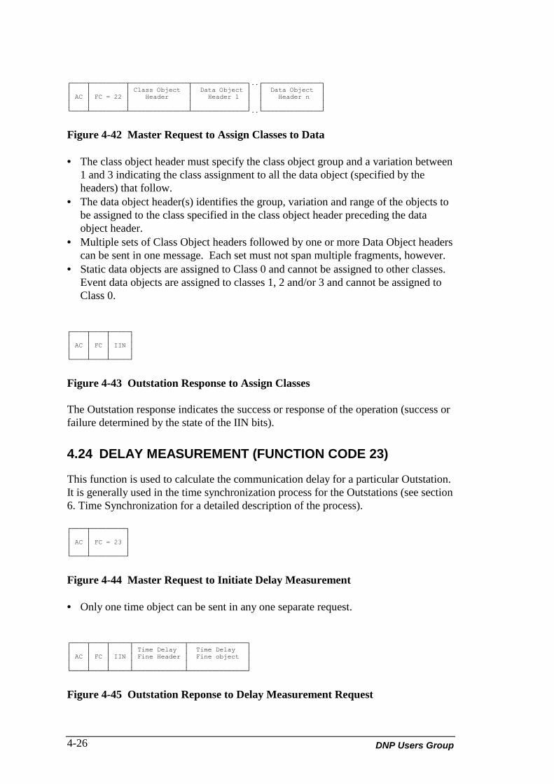
DNP Users Group4-26
┌────┬─────────┬───────────────┬──────────────┐..┌───────────────┐│ │ │ Class Object │ Data Object │ │ Data Object ││ AC │ FC = 22 │ Header │ Header 1 │ │ Header n ││ │ │ │ │ │ │└────┴─────────┴───────────────┴──────────────┘..└───────────────┘
Figure 4-42 Master Request to Assign Classes to Data
• The class object header must specify the class object group and a variation between1 and 3 indicating the class assignment to all the data object (specified by theheaders) that follow.
• The data object header(s) identifies the group, variation and range of the objects tobe assigned to the class specified in the class object header preceding the dataobject header.
• Multiple sets of Class Object headers followed by one or more Data Object headerscan be sent in one message. Each set must not span multiple fragments, however.
• Static data objects are assigned to Class 0 and cannot be assigned to other classes.Event data objects are assigned to classes 1, 2 and/or 3 and cannot be assigned toClass 0.
┌────┬────┬─────┐│ │ │ ││ AC │ FC │ IIN ││ │ │ │└────┴────┴─────┘
Figure 4-43 Outstation Response to Assign Classes
The Outstation response indicates the success or response of the operation (success orfailure determined by the state of the IIN bits).
4.24 DELAY MEASUREMENT (FUNCTION CODE 23)
This function is used to calculate the communication delay for a particular Outstation.It is generally used in the time synchronization process for the Outstations (see section6. Time Synchronization for a detailed description of the process).
┌────┬─────────┐│ │ ││ AC │ FC = 23 ││ │ │└────┴─────────┘
Figure 4-44 Master Request to Initiate Delay Measurement
• Only one time object can be sent in any one separate request.
┌────┬────┬─────┬─────────────┬───────────────┐│ │ │ │ Time Delay │ Time Delay ││ AC │ FC │ IIN │ Fine Header │ Fine object ││ │ │ │ │ │└────┴────┴─────┴─────────────┴───────────────┘
Figure 4-45 Outstation Reponse to Delay Measurement Request

DNP V3.00 Application Layer (Version 0.03) 4-27
The Outstation responds with the Time Delay Fine object. This object states thenumber of milliseconds elapsed between the Outstation receiving the first bit of thefirst byte of the request and the time of transmission of the first bit of the first byte ofthe response.

DNP Users Group4-28
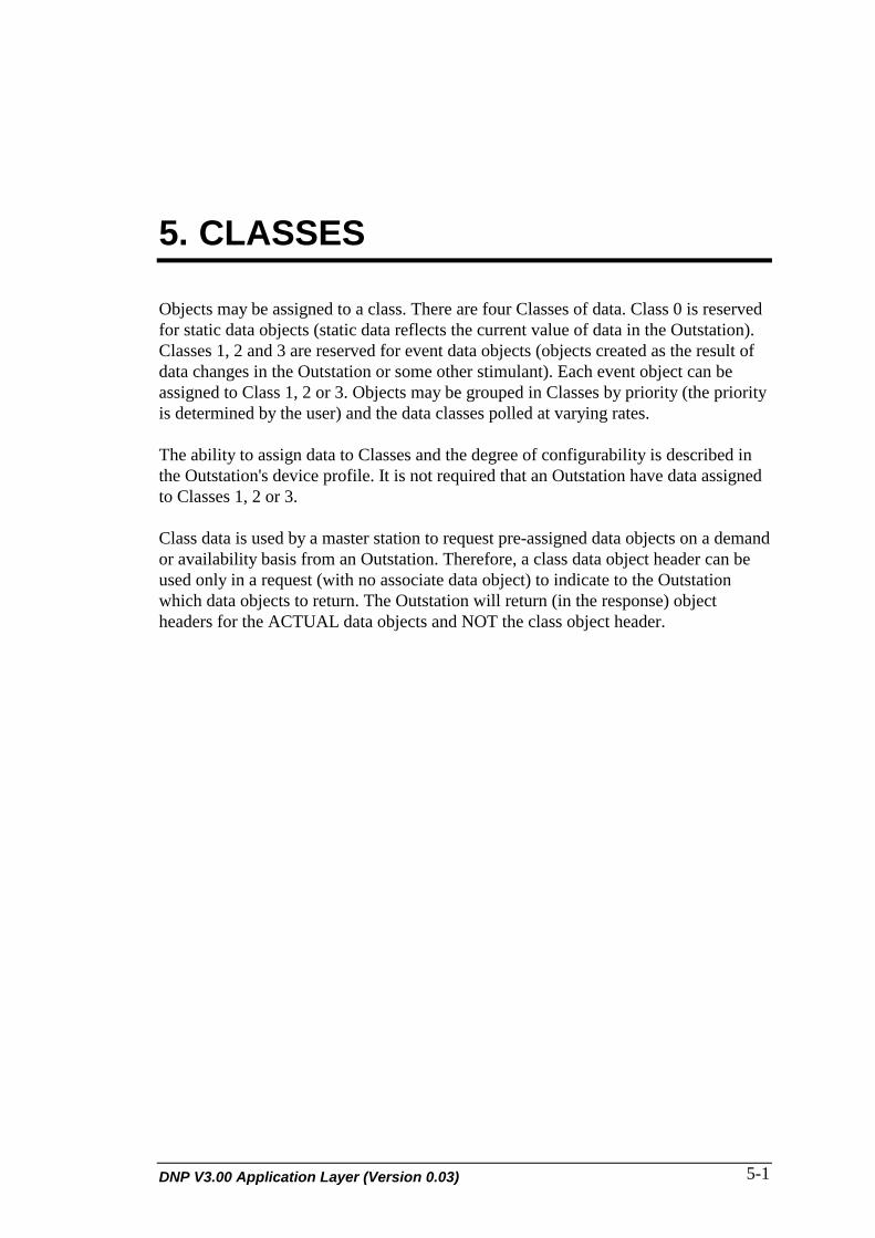
DNP V3.00 Application Layer (Version 0.03) 5-1
5. CLASSES
Objects may be assigned to a class. There are four Classes of data. Class 0 is reservedfor static data objects (static data reflects the current value of data in the Outstation).Classes 1, 2 and 3 are reserved for event data objects (objects created as the result ofdata changes in the Outstation or some other stimulant). Each event object can beassigned to Class 1, 2 or 3. Objects may be grouped in Classes by priority (the priorityis determined by the user) and the data classes polled at varying rates.
The ability to assign data to Classes and the degree of configurability is described inthe Outstation's device profile. It is not required that an Outstation have data assignedto Classes 1, 2 or 3.
Class data is used by a master station to request pre-assigned data objects on a demandor availability basis from an Outstation. Therefore, a class data object header can beused only in a request (with no associate data object) to indicate to the Outstationwhich data objects to return. The Outstation will return (in the response) objectheaders for the ACTUAL data objects and NOT the class object header.

DNP Users Group5-2
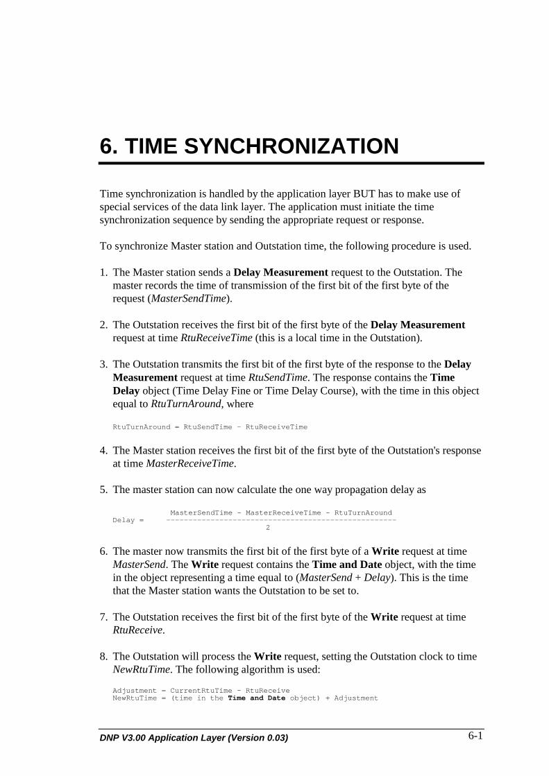
DNP V3.00 Application Layer (Version 0.03) 6-1
6. TIME SYNCHRONIZATION
Time synchronization is handled by the application layer BUT has to make use ofspecial services of the data link layer. The application must initiate the timesynchronization sequence by sending the appropriate request or response.
To synchronize Master station and Outstation time, the following procedure is used.
1. The Master station sends a Delay Measurement request to the Outstation. Themaster records the time of transmission of the first bit of the first byte of therequest (MasterSendTime).
2. The Outstation receives the first bit of the first byte of the Delay Measurementrequest at time RtuReceiveTime (this is a local time in the Outstation).
3. The Outstation transmits the first bit of the first byte of the response to the DelayMeasurement request at time RtuSendTime. The response contains the TimeDelay object (Time Delay Fine or Time Delay Course), with the time in this objectequal to RtuTurnAround, where
RtuTurnAround = RtuSendTime - RtuReceiveTime
4. The Master station receives the first bit of the first byte of the Outstation's responseat time MasterReceiveTime.
5. The master station can now calculate the one way propagation delay as MasterSendTime - MasterReceiveTime - RtuTurnAround Delay = ---------------------------------------------------- 2
6. The master now transmits the first bit of the first byte of a Write request at timeMasterSend. The Write request contains the Time and Date object, with the timein the object representing a time equal to (MasterSend + Delay). This is the timethat the Master station wants the Outstation to be set to.
7. The Outstation receives the first bit of the first byte of the Write request at timeRtuReceive.
8. The Outstation will process the Write request, setting the Outstation clock to timeNewRtuTime. The following algorithm is used:
Adjustment = CurrentRtuTime - RtuReceive NewRtuTime = (time in the Time and Date object) + Adjustment
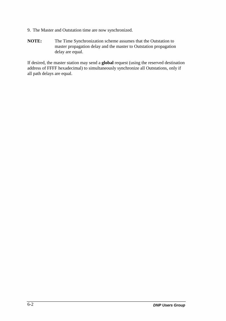
DNP Users Group6-2
9. The Master and Outstation time are now synchronized.
NOTE: The Time Synchronization scheme assumes that the Outstation tomaster propagation delay and the master to Outstation propagationdelay are equal.
If desired, the master station may send a global request (using the reserved destinationaddress of FFFF hexadecimal) to simultaneously synchronize all Outstations, only ifall path delays are equal.

DNP V3.00 Application Layer (Version 0.03) 7-1
7. BINARY INPUT WITH TIMEEVENTS
An Outstation will often transmit Binary Input with Time or Binary Input withRelative Time objects when digital input points changes state. Binary input eventobjects are transmitted in different formats depending on different conditions.
1) Outstation Time Synchronized, one event object to send. The data is transmittedin the Binary Input with Time object format.
2) Outstation Time Synchronized, several event object to send. The Time andDate Common Time of Occurrence object is transmitted followed by severalBinary Input with Relative Time objects. The time in the Time and Date CommonTime of Occurrence object is the time of the oldest object. The relative times startat 0 (for the oldest object) and range upwards relative to the Date and Time object.
3) Outstation Time NOT Synchronized, one or more event object to send. TheUnsynchronized Common Time and Date object is transmitted followed by one ormore Binary Input with Relative Time objects. The time in the Time and DateCommon Time of Occurrence object is the time of the oldest object. The relativetimes start at 0 (for the oldest object) and range upwards relative to the Time andDate object.

DNP Users Group7-2

DNP V3.00 Application Layer (Version 0.03) 8-1
8. FILE TRANSFER
The File Identifier Object (FIO) may be used to transfer data files betweenOutstations and master stations. This is commonly used to write configurationsfrom a master to an Outstation or read configurations from an Outstation to amaster.
The functionality of the File Identifier Object allows configurationinformation to be routed to Outstations via intermediate Data Concentrators.A data concentrator is located between a master station and an Outstation - it iseffectively an Outstation to the master station and a master station to theOutstation. Note that a Data Concentrator is not just a communication node - itdoes not directly route messages between a master station and an Outstation.
The File Identifier Object is always passed to an Outstation in a request usingthe WRITE function code. The action to be done (reading, writing orotherwise) is specified by the File_Function field within the object. Theresponse always uses the RESPONSE function code. However, an outstationcan send an unsolicited message containing a FIO.
The File Identifier Object contains routing information in its File_Name field.This field describes how the object is to be routed from the master station,through any number of intermediate Data Concentrators, to the Outstation.
The interpretation of the File_Name field is dependent on the DataConcentrator through which the object is being routed.
8.1 FILE IDENTIFIER OBJECTS PERFORMING WRITEFUNCTIONS
This section describes how a File Identifier Object is passed from a masterstation through a Data Concentrator to an Outstation. The Outstation may beanother Data Concentrator. Note that the request message is using the WRITEfunction code. The File_Function field in the object will be WRITE,APPEND, INSERT, DELETE or ERASE. The object may or may not containdata (no data for DELETE or ERASE).
DNP Users Group8-2
The following Nomenclature is used:• Outstation Application - This is the software application in the Data
Concentrator that communicates to the master station. It is an Outstationwith respect to the master station.
• Master Application - This is the software application in the DataConcentrator that communicates to the Outstation. It is a master withrespect to the Outstation.
The master station send the request (WRITE function code) with the FileIdentifier Object to the Outstation Application. For the request, the followingconditions must be satisfied;• DNP WRITE Function Code is used in the request.• File_Function field in the object is set to WRITE, APPEND, INSERT,
DELETE or ERASE.• File_Name field contains an ASCII character string. The length and
contents of the string is dependant on the Data Concentrator. The Harrisimplementation uses a string, the first 9 character of which are"/DNPDCAxx", where xx (2 ASCII characters) contains the MasterApplication number to which this File Identifier Object must be routed.This information routes the object from the Outstation Application to theMaster Application within the Data Concentrator, which will send it on tothe Outstation.
If the above conditions are met, the following sequence occurs:1) Outstation Application sends a CONFIRMation response to the master
station (if the CON bit in the Request Header is set).2) Outstation Application removes the first 9 characters (for HARRIS
implementation) from the FILE_NAME field, modifying other FileIdentifier Object fields if necessary.
3) Outstation Application sends the File Identifier Object to the MasterApplication.
4) Master Application sends a request (WRITE function code) containingthe File Identifier Object to the appropriate Outstation.
5) If a CONFIRMation Response is required, the Master Applicationwaits for this response.
6) Master Application now waits for the response containing the FileIdentifier Object. The object in the response contains the status of thecommand specified in the File_Function field. When this object isreceived, the Master Application sends it to the Outstation Application.If the Master Application does not receive the object, a negativeacknowledgement is sent to the Outstation Application.
7) Upon receipt of a response File Identifier Object or negativeacknowledgement (from the Master Application), the OutstationApplication sends a response to the master. The transaction iscomplete.
The response to the request uses the RESPONSE Function Code. It containsthe File Identifier Object, which contains the status of the operation requested
DNP V3.00 Application Layer (Version 0.03) 8-3
in the File_Function field, with no data records. If the Outstation Applicationreceives a response from the Master Application, this response contains a FileIdentifier Object. The Outstation Application does not need to change thisresponse. If the Outstation Application receives a negative acknowledgementfrom the Master Application, it will modify and set the following fields in theresponse File Identifier Object:
START_RECORD = END_RECORD = 0FILE_SIZE = 0FILE_FUNCTION = RESPONSEPERMISSION = 0STATUS = 2 Master Application was unable to pass the File
Identifier Object to the Master Application.4 Operation unsuccessful because the device addressed by
FILE_ID is offline.4 Operation unsuccessful because a negative
acknowledgement received from the MasterApplication.
The File_Name field is designed so that File Identifier Objects containingconfigurations can be downloaded to an Outstation via any number ofintermediate data concentrators.
Figure 8-1 is a simplistic example illustrating how the File Identifier Object ispassed through the system from a master station to an Outstation via two dataconcentrators.
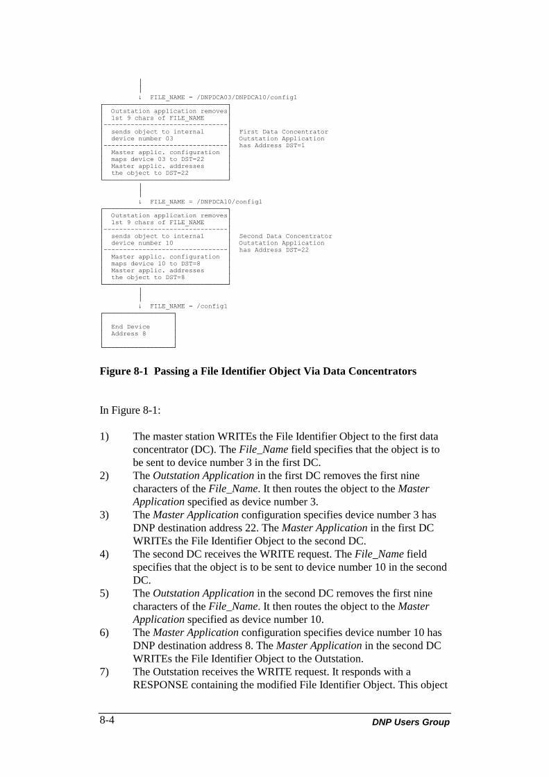
DNP Users Group8-4
│ │ ↓ FILE_NAME = /DNPDCA03/DNPDCA10/config1┌────────────────────────────────┐│ Outstation application removes││ 1st 9 chars of FILE_NAME ││--------------------------------││ sends object to internal │ First Data Concentrator│ device number 03 │ Outstation Application│--------------------------------│ has Address DST=1│ Master applic. configuration ││ maps device 03 to DST=22 ││ Master applic. addresses ││ the object to DST=22 │└────────────────────────────────┘ │ │ ↓ FILE_NAME = /DNPDCA10/config1┌────────────────────────────────┐│ Outstation application removes││ 1st 9 chars of FILE_NAME ││--------------------------------││ sends object to internal │ Second Data Concentrator│ device number 10 │ Outstation Application│--------------------------------│ has Address DST=22│ Master applic. configuration ││ maps device 10 to DST=8 ││ Master applic. addresses ││ the object to DST=8 │└────────────────────────────────┘ │ │ ↓ FILE_NAME = /config1┌──────────────────┐│ ││ End Device ││ Address 8 ││ │└──────────────────┘
Figure 8-1 Passing a File Identifier Object Via Data Concentrators
In Figure 8-1:
1) The master station WRITEs the File Identifier Object to the first dataconcentrator (DC). The File_Name field specifies that the object is tobe sent to device number 3 in the first DC.
2) The Outstation Application in the first DC removes the first ninecharacters of the File_Name. It then routes the object to the MasterApplication specified as device number 3.
3) The Master Application configuration specifies device number 3 hasDNP destination address 22. The Master Application in the first DCWRITEs the File Identifier Object to the second DC.
4) The second DC receives the WRITE request. The File_Name fieldspecifies that the object is to be sent to device number 10 in the secondDC.
5) The Outstation Application in the second DC removes the first ninecharacters of the File_Name. It then routes the object to the MasterApplication specified as device number 10.
6) The Master Application configuration specifies device number 10 hasDNP destination address 8. The Master Application in the second DCWRITEs the File Identifier Object to the Outstation.
7) The Outstation receives the WRITE request. It responds with aRESPONSE containing the modified File Identifier Object. This object
DNP V3.00 Application Layer (Version 0.03) 8-5
contains the status of the operation. It is transmitted to the MasterApplication in the second DC.
8) The Master Application in the second DC transfers the response FileIdentifier Object to the Outstation Application.
9) The Outstation Application sends a RESPONSE containing the FileIdentifier Object to the first DC.
10) The Master Application in the first DC transfers the response FileIdentifier Object to the Outstation Application.
11) The Outstation Application in the first DC sends a RESPONSEcontaining the File Identifier Object to the DNP master station.
NOTES:• This functionality requires the DNP master station to have a larger response
timeout than the Outstation Application in the first DC, which in turn has alarger response timeout than the Outstation Application in the second DC.
• The DNP master station must have detailed configuration and routinginformation in order to construct the File_Name field.
• AN Outstation Application will not receive while it waits for a responsefrom a down stream device. It is "locked out" to master requests.
8.2 FILE IDENTIFIER OBJECT PERFORMING READFUNCTIONS
This section describes how a File Identifier Object is used to perform readfunctions. Note that the object is passed to applications via a request using theWRITE function code. The File_Function field is set to READ.
The master station can read the File Identifier Object when the followingconditions are met:• The DNP WRITE Function Code is used in the request.• The File_Function field in the File Identifier Object received in the
request is set to READ.• The File_Name field contains an ASCII character string. The length
and contents of the string is dependant on the DC. The HARRISimplementation uses a string, the first 9 character of which are"/DNPDCAxx", where xx (2 ASCII characters) contains the MasterApplication number of the destination for this File Identifier Object.This information routes the object through the DC to the MasterApplication which will send it on from the DC to the Outstation.
If the above conditions are met, the following sequence occurs;1) The Outstation Application sends a CONFIRMation response to the
DNP master station (if required).2) The Outstation Application removes the first 9 characters from the
File_Name field( for HARRIS implementation), modifying the FileIdentifier Object as required.
3) The Outstation Application sends a READ command with the FileIdentifier Object to the Master Application.

DNP Users Group8-6
5) The Master Application sends a READ command with the FileIdentifier Object to the appropriate Outstation.
6) If a CONFIRMation Response is required, the Master Applicationwaits for this response.
7) The Master Application now waits for the response containing therequested File Identifier Object. When this object is received, theMaster Application sends the response to the Outstation Application. Ifthe Master Application does not receive the object, a negativeacknowledgement is sent to the Outstation Application.
8) Upon receipt of an response File Identifier Object or negativeacknowledgement, the Outstation Application sends a response to themaster. The transaction is complete.
Some error conditions can occur in the above sequence. In the cases where theOutstation Application cannot pass the request to the Master Application or anegative acknowledgement is received from the Master Application, theOutstation Application returns the File Identifier Object received as part of therequest to the master station.
The Outstation Application will modify and set the following fields in theresponse File Identifier Object;
START_RECORD = END_RECORD = 0FILE_SIZE = 0FILE_FUNCTION = RESPONSEPERMISSION = 0STATUS = 2 Outstation Application was unable to pass the File
Identifier Object to the Master Application.4 Operation unsuccessful because the device addressed by
FILE_ID is offline.4 Operation unsuccessful because a negative
acknowledgement received from the MasterApplication.

DNP V3.00 Application Layer (Version 0.03) 1
LIST OF ABBREVIATIONS ANDACRONYMS
AC application controlAPCI application protocol control informationAPDU application protocol data unitASDU application service data unit
COS change of state
DA distribution automationDC data concentratorDNP distributed network protocolDUI data unit identifiers
EPA enhanced protocol architecture
IEC International Electrotechnical CommissionIIN internal indicationsIO information objectsISO International Standards Organization
OSI Open System InterconnectionPDU protocol data unit
RTU remote terminal unit
SCADA supervisory control and data acquisitionSEQ sequence number

DNP Users Group
DNP PRODUCT DOCUMENTATION
DNP V3.00DATA OBJECT LIBRARY
Document Version: 0.02Internal File: P009-OBL
Associated Software Release: DNP V3.00

NOTICE OF RIGHTS - DNP USERS GROUP
The contents of this manual are the property of the DNP UsersGroup. Revisions or additions to the definition and functionality ofthe Distributed Network Protocol cannot be made without expresswritten agreement from the DNP Users Group or its duly authorizedparty. In addition, no part of this document may be altered orrevised or added to in any form or by any means, except as permittedby written agreement with the DNP Users Group or a Party dulyauthorized by the DNP Users Group.
As a Party, duly authorized by the DNP Users Group, HarrisCorporation has made every reasonable attempt to ensure thecompleteness and accuracy of this document, however, theinformation contained in this manual is subject to change withoutnotice, and does not represent a commitment on the part of HarrisCorporation or the DNP Users Group. An update program for DNPdocuments is provided upon request by Harris Corporation onbehalf of the DNP Users Group.
TRADEMARK NOTICES
Brand and product names mentioned in this document aretrademarks or registered trademarks of their respective companies.

DNP V3.00 Data Object Library (Version 0.02) i
TABLE OF CONTENTS
ABOUT THIS DOCUMENT vPURPOSE OF THIS SPECIFICATION vWHO SHOULD USE THIS SPECIFICATION vHELP AND ADDITIONAL DOCUMENTATION vHOW THIS SPECIFICATION IS ORGANIZED viCONVENTIONS USED IN THIS SPECIFICATION vi
1. OVERVIEW 1-1
2. DECLARATION RULES FOR INFORMATION ELEMENTS 2-12.1 GENERAL 2-1
3. GENERAL RULES 3-13.1 LIBRARY STRUCTURE 3-13.2 POINT NUMBERING 3-4
4. BINARY INPUT OBJECT DEFINITIONS 4-14.1 SINGLE-BIT BINARY INPUT 4-14.2 BINARY INPUT WITH STATUS 4-24.3 BINARY INPUT CHANGE WITHOUT TIME 4-34.4 BINARY INPUT CHANGE WITH TIME 4-54.5 BINARY INPUT CHANGE WITH RELATIVE TIME 4-7
5. BINARY OUTPUT OBJECT DEFINITIONS 5-15.1 BINARY OUTPUT 5-15.2 BINARY OUTPUT STATUS 5-25.3 CONTROL RELAY OUTPUT BLOCK 5-35.4 PATTERN CONTROL BLOCK 5-65.5 PATTERN MASK 5-7
6. COUNTER OBJECT DEFINITIONS 6-16.1 32-BIT BINARY COUNTER 6-16.2 16-BIT BINARY COUNTER 6-36.3 32-BIT DELTA COUNTER 6-46.4 16-BIT DELTA COUNTER 6-56.5 32-BIT COUNTER WITHOUT FLAG 6-66.6 16-BIT COUNTER WITHOUT FLAG 6-76.7 32-BIT DELTA COUNTER WITHOUT FLAG 6-8

DNP Users Groupii
6.8 16-BIT DELTA COUNTER WITHOUT FLAG 6-96.9 32-BIT FROZEN COUNTER 6-106.10 16-BIT FROZEN COUNTER 6-116.11 32-BIT FROZEN DELTA COUNTER 6-126.12 16-BIT FROZEN DELTA COUNTER 6-136.13 32-BIT FROZEN COUNTER WITH TIME OF FREEZE 6-146.14 16-BIT FROZEN COUNTER WITH TIME OF FREEZE 6-156.15 32-BIT FROZEN DELTA COUNTER WITH TIME OF FREEZE 6-166.16 16-BIT FROZEN DELTA COUNTER WITH TIME OF FREEZE 6-186.17 32-BIT FROZEN COUNTER WITHOUT FLAG 6-206.18 16-BIT FROZEN COUNTER WITHOUT FLAG 6-216.19 32-BIT FROZEN DELTA COUNTER WITHOUT FLAG 6-226.20 16-BIT FROZEN DELTA COUNTER WITHOUT FLAG 6-236.21 32-BIT COUNTER CHANGE EVENT WITHOUT TIME 6-246.22 16-BIT COUNTER CHANGE EVENT WITHOUT TIME 6-256.23 32-BIT DELTA COUNTER CHANGE EVENT WITHOUT TIME 6-266.24 16-BIT DELTA COUNTER CHANGE EVENT WITHOUT TIME 6-276.25 32-BIT COUNTER CHANGE EVENT WITH TIME 6-286.26 16-BIT COUNTER CHANGE EVENT WITH TIME 6-296.27 32-BIT DELTA COUNTER CHANGE EVENT WITH TIME 6-306.28 16-BIT DELTA COUNTER CHANGE EVENT WITH TIME 6-316.29 32-BIT COUNTER CHANGE EVENT WITHOUT TIME 6-326.30 16-BIT FROZEN COUNTER EVENT WITHOUT TIME 6-336.31 32-BIT FROZEN DELTA COUNTER EVENT WITHOUT TIME 6-346.32 16-BIT FROZEN DELTA COUNTER WITHOUT TIME 6-356.33 32-BIT FROZEN COUNTER EVENT WITH TIME 6-366.34 16-BIT FROZEN COUNTER EVENT WITH TIME 6-376.35 32-BIT FROZEN DELTA COUNTER EVENT WITH TIME 6-386.36 16-BIT FROZEN DELTA COUNTER EVENT WITH TIME 6-39
7. ANALOG INPUT OBJECT DEFINITIONS 7-17.1 32-BIT ANALOG INPUT 7-17.2 16-BIT ANALOG INPUT 7-37.3 32-BIT ANALOG INPUT WITHOUT FLAG 7-47.4 16-BIT ANALOG INPUT WITHOUT FLAG 7-57.5 32-BIT FROZEN ANALOG INPUT 7-67.6 16-BIT FROZEN ANALOG INPUT 7-77.7 32-BIT FROZEN ANALOG INPUT WITH TIME OF FREEZE 7-87.8 16-BIT FROZEN ANALOG INPUT WITH TIME OF FREEZE 7-107.9 32-BIT FROZEN ANALOG INPUT WITHOUT FLAG 7-127.10 16-BIT FROZEN ANALOG INPUT WITHOUT FLAG 7-137.11 32-BIT ANALOG CHANGE EVENT WITHOUT TIME 7-147.12 16-BIT CHANGE EVENT WITHOUT TIME 7-157.13 32-BIT ANALOG CHANGE EVENT WITH TIME 7-167.14 16-BIT ANALOG CHANGE EVENT WITH TIME 7-177.15 32-BIT FROZEN ANALOG EVENT WITHOUT TIME 7-187.16 16-BIT FROZEN ANALOG EVENT WITHOUT TIME 7-197.17 32-BIT FROZEN ANALOG EVENT WITH TIME 7-207.18 16-BIT FROZEN ANALOG EVENT WITH TIME 7-22

DNP V3.00 Data Object Library (Version 0.02) iii
8. ANALOG OUTPUT OBJECT DEFINITIONS 8-18.1 32-BIT ANALOG OUTPUT STATUS 8-18.2 16-BIT ANALOG OUTPUT STATUS 8-38.3 32-BIT ANALOG OUTPUT BLOCK 8-48.4 16-BIT ANALOG OUTPUT BLOCK 8-5
9. TIME OBJECT DEFINITIONS 9-19.1 TIME AND DATE 9-19.2 TIME AND DATE WITH INTERVAL 9-29.3 TIME AND DATE CTO 9-39.4 UN-SYNCHRONIZED TIME AND DATE CTO 9-49.5 TIME DELAY COARSE 9-59.6 TIME DELAY FINE 9-6
10. CLASS OBJECT DEFINITIONS 10-110.1 CLASS 0 DATA 10-110.2 CLASS 1 DATA 10-210.3 CLASS 2 DATA 10-310.4 CLASS 3 DATA 10-4
11. FILE OBJECT DEFINITIONS 11-111.1 FILE IDENTIFIER 11-1
12. DEVICE OBJECT DEFINITIONS 12-112.1 INTERNAL INDICATIONS 12-112.2 STORAGE OBJECT 12-212.3 DEVICE PROFILE 12-312.4 PRIVATE REGISTRATION OBJECT 12-612.5 PRIVATE REGISTRATION OBJECT DESCRIPTOR 12-7
13. APPLICATION OBJECT DEFINITIONS 13-113.1 APPLICATION IDENTIFIER 13-1
14. ALTERNATE NUMERIC OBJECT DEFINITIONS 14-114.1 SHORT FLOATING POINT 14-114.2 LONG FLOATING POINT 14-414.3 EXTENDED FLOATING POINT 14-614.4 SMALL-PACKED BINARY CODED DECIMAL 14-814.5 MEDIUM-PACKED BINARY CODED DECIMAL 14-914.6 LARGE-PACKED BINARY CODED DECIMAL 14-10
LIST OF ABBREVIATIONS AND ACRONYMS

DNP Users Groupiv
LIST OF TABLES
TABLE 2-1 DATA TYPES 2-1TABLE 2-2 BIT POSITIONS 2-2

DNP V3.00 Data Object Library (Version 0.02) v
ABOUT THIS DOCUMENT
PURPOSE OF THIS SPECIFICATION
This document defines coding specifications of Distributed Network Protocol (DNP)information elements or data objects used in the DNP Application Layer. The objectsyntax is specified as well as the semantics of each object. In the case of compoundobjects, the semantics of each component is described.
WHO SHOULD USE THIS SPECIFICATION
All programmers, implementers or engineers interested in the structure of applicationinformation objects used in the DNP Application Layer.
HELP AND ADDITIONAL DOCUMENTATION
The following documentation may be helpful.• DNP V3.00 Data Link Layer (P009-0PD.DL).• DNP V3.00 Application Layer (P009-0PD.APP)• DNP V3.00 Transport Functions (P009-0PD.TF)
DNP Users Groupvi
HOW THIS SPECIFICATION IS ORGANIZED
This document is organized into 13 sections as outlined below.
1. OVERVIEW
2. DECLARATION RULES FOR INFORMATION ELEMENTSCovers the rules for construction and interpretation of the data objects.
3. GENERAL RULESDescribes the rules governing each of the currently defined objects.
The rest of the sections provide detailed definitions of each type of object.
4. BINARY INPUT OBJECT DEFINITIONS
5. BINARY OUTPUT OBJECT DEFINITIONS
6. COUNTER OBJECT DEFINITIONS
7. ANALOG INPUT OBJECT DEFINITIONS
8. ANALOG OUTPUT OBJECT DEFINITIONS
9. TIME OBJECT DEFINITIONS
10. CLASS OBJECT DEFINITIONS
11. FILE OBJECT DEFINITIONS
12. DEVICE OBJECT DEFINITIONS
13. APPLICATION OBJECT DEFINITIONS
14. ALTERNATE NUMERIC OBJECT DEFINITIONS
LIST OF ABBREVIATIONS AND ACRONYMS
CONVENTIONS USED IN THIS SPECIFICATION
This document deviates from the IEC conventions for bit position numbering. Bitpositions are numbered from 0 through n, with 0 to the top right and n to the bottomleft.

DNP V3.00 Data Object Library (Version 0.02) vii

DNP V3.00 Data Object Library (Version 0.02) 1-1
1. OVERVIEW
The intelligent devices which use the DNP Application Layer protocol are capable ofmonitoring, controlling and/or producing a large number of different pieces of databoth at the hardware and software levels. These pieces of data, called informationelements (IEC 870-5-3: General Structure of Application Data), are processed andstored as information objects and these can be packaged for transmission asapplication data units. All devices provide stored information elements as informationobjects in the same format. These formats are described within this document.
This document will be revised and new information elements or objects will be addedas necessary, and as authorized by the DNP User's Group.

DNP Users Group1-2
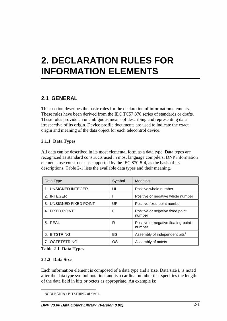
DNP V3.00 Data Object Library (Version 0.02) 2-1
2. DECLARATION RULES FORINFORMATION ELEMENTS
2.1 GENERAL
This section describes the basic rules for the declaration of information elements.These rules have been derived from the IEC TC57 870 series of standards or drafts.These rules provide an unambiguous means of describing and representing datairrespective of its origin. Device profile documents are used to indicate the exactorigin and meaning of the data object for each telecontrol device.
2.1.1 Data Types
All data can be described in its most elemental form as a data type. Data types arerecognized as standard constructs used in most language compilers. DNP informationelements use constructs, as supported by the IEC 870-5-4, as the basis of itsdescriptions. Table 2-1 lists the available data types and their meaning.
Data Type Symbol Meaning
1. UNSIGNED INTEGER UI Positive whole number
2. INTEGER I Positive or negative whole number
3. UNSIGNED FIXED POINT UF Positive fixed point number
4. FIXED POINT F Positive or negative fixed pointnumber
5. REAL R Positive or negative floating-pointnumber
6. BITSTRING BS Assembly of independent bits1
7. OCTETSTRING OS Assembly of octets
Table 2-1 Data Types
2.1.2 Data Size
Each information element is composed of a data type and a size. Data size i, is notedafter the data type symbol notation, and is a cardinal number that specifies the lengthof the data field in bits or octets as appropriate. An example is:
1BOOLEAN is a BITSTRING of size 1.

DNP Users Group2-2
BS12 specifies a BITSTRING of 12 bits.
2.1.3 Bit Position
In defining information objects, which are a combination of information elements, theposition of individual bits can be significant. The bit position of a specified field ofdata size i is denoted in square brackets [p1..pn], where p1 and pn denote the first andthe last bits of the field. The order of bits is shown in Table 2-2, below.
BITS 7 6 5 4 3 2 1 0
OCTETS Data Size i
1 7 6 5 4 3 2 1 0
2 15 14 13 12 11 10 9 8
.
...
.
...
.
...
.
...
.
.
j 8j-1 8j-2 8j-3 8j-4 8j-5 8j-6 8j-7 8j-8
Table 2-2 Bit Positions
2.1.4 Element Value
If applicable, a selected range and a selected code of values of the declared data fieldis denoted within angle brackets: <v1..vn code>. In general this is declared by therange of admitted values and by a term that identifies the used code. Terms thatidentify codes are: binary code (BIN), binary coded decimal (BCD), ASCII (ASCII),etc. The default code declaration is binary if no term is used.
2.1.5 Compound Elements
Compound data fields are information elements composed of different data fields withsuccessive bit allocations. Compound data fields are declared by listing individualdata fields separated by commas or listed in a column, within curly brackets. Afollowing list declares the data types, the sizes, the bit allocations and the functionalpurpose of the individual data fields. The first declared data field begins with bitposition 0, the other fields use successive bit allocations:
'Information Element = CPi {data field 1, data field 2,...}or{data field 1 = data type 1 size i1[0..i-1] = function 1data field 2 = data type 2 size i2[i1..i1+i2-1] = function 2etc.}
2.1.6 Sequence Elements

DNP V3.00 Data Object Library (Version 0.02) 2-3
Sequence data fields are information elements composed of different data fields.Sequences of data fields are declared as compound data fields, however each fieldbegins bit allocation 0:
'Information Element = SQi {data field 1, data field 2, ...}or{data field 1 size i1[1..i1] = function 1data field 2 size i2[1..i2] = function 2etc.}

DNP Users Group2-4

DNP V3.00 Data Object Library (Version 0.02) 3-1
3. GENERAL RULES
This section will describe the general rules that apply to the DNP data objects. Theserules apply to all the current objects (except where noted) and all future objects.
3.1 LIBRARY STRUCTURE
The DNP application layer has an 8-bit object and an 8-bit variation field used todenote the data object. The 8-bit object denotes a general type of data such as staticbinary data. The variation of this object gives a different representation of the samedata point, such as the size of the object or whether or not the object has flaginformation.
There are generally four different categories of data within each data type, as outlinedbelow:
• Static Objects: The objects which reflect the current value of the field pointor software point.
• Event Objects: The objects which are generated as a result of data changingor some other stimulant. These are historical objects reflecting the value ofdata at some time in the past.
• Frozen Static Objects: The objects which reflect the current frozen value ofthe field point or software point. Data is frozen as a result of the data freezerequests. (Refer to the DNP V3.00 Application Layer, P009-0PD.APP.)
• Frozen Event Objects: The objects which are generated as a result of frozendata changing or some other stimulant. These are historical objects reflectingthe value of changed data at some time in the past.
Each category should be represented with a different object. All the classes of adifferent data type should also be organized in the same range of object numbers. Sofar, the following groupings have been created for all traditional SCADA/DA datatypes and several non-traditional data types. These are as follows:
3.1.1 Binary Input
The binary input grouping contains all objects that represent binary (status orBoolean) input information. The objects 1 - 9 are reserved for these objects.

DNP Users Group3-2
3.1.2 Binary Output
The binary output grouping contains all objects that represent binary output or relaycontrol information. The objects 10 - 19 are reserved for these objects.
3.1.3 Counters
The counter grouping contains all objects that represent counters. The objects 20 - 29are reserved for these objects.
3.1.4 Analog Input
The analog input grouping contains all objects that represent analog input information.The objects 30 - 39 are reserved for these objects.
3.1.5 Analog Output
The analog output grouping contains all objects that represent analog outputinformation. The objects 40 - 49 are reserved for these objects.
3.1.6 Time
The time grouping contains all objects that represent time in absolute or relative formin any resolution. The objects 50 - 59 are reserved for these objects.
3.1.7 Class
The class grouping contains all objects that represent data classes or data priority. Theobjects 60 - 69 are reserved for these objects.
3.1.8 Files
The files grouping contains all objects that represent files or a file system. The objects70 - 79 are reserved for these objects.
3.1.9 Devices
The devices grouping contains all objects that represent device (rather than point)information. The objects 80 - 89 are reserved for these objects.
3.1.10 Applications
The applications grouping contains all objects that represent software applications oroperating system processes. The objects 90 - 99 are reserved for these objects.
3.1.11 Alternate Numeric
The alternate numeric grouping contains all objects that represent alternate or customnumeric representations. The objects 100 - 109 are reserved for these objects.

DNP V3.00 Data Object Library (Version 0.02) 3-3
3.1.12 Future Expansion
The future expansion grouping is reserved for future or custom expansion of the DNPprotocol. The objects 110 - 254 are reserved for these objects.
3.1.13 Reserved
The objects 0 and 255 are permanently reserved and should not be used to denote anyDNP object. Applications which use these object numbers may not be compatiblewith future versions of DNP.
DNP Users Group3-4
3.2 POINT NUMBERING
The following rules apply to the interpretation of the object point number (DNPApplication Layer range field) in conjunction with objects and variations.
Rule 1:Point i of object x, variation y represents the same physical point as point i, object x,variation z, where y and z are variations of object x.
For example: A device has 16 running counters (object 20) numbered 0 to 15. Point 5can be asked for in four different ways:
• Obj 20, var 1, range 5 returns the running value of counter 5 in 32-bit format.• Obj 20, var 2, range 5 reports the same information, only in 16-bit format.• Obj 20, var 3, range 5 returns the number of counts accumulated in counter 5 since
the last time it was reported, again in 32-bit format.• Obj 20, var 4, range 5 reports the same information, only in 16-bit format.
RULE 2:Point i of object x can be reported in one of many variations (i.e. it can be a 16-bit or32-bit counter). When reported as an event, point i can be returned in either one of thevariations for that object. The exact variation to return is an application specificdecision, however an application should report only ONE event object in any onevariation for each event. When responding to a request for Class data or variation 0 ofobject x, there should be only one variation of the object returned.
RULE 3:Point i within different objects of the same grouping are not necessarily unique,however, within each of the binary input, binary output, analog input, analog outputand counter groupings the following rules apply.
(a) Point i in the static object is the same physical point as point i in theevent object.
(b) Point i in the frozen object is the same physical point as point i in thefrozen event object.
For example: For binary inputs, point i in obj 1 var 1 and 2 is the same point as pointi in obj 2 var 1, 2 and 3 (static and event correlation). For counters, point i in obj 20var 1, 2, 3, and 4 is the same point as point i in obj 22 var 1, 2, 3, 4, 5, 6, 7, and 8(static and event correlation). In addition, point i in obj 21 var 1, 2, 3, 4, 5, 6, 7, and 8is the same point as point i in obj 23 var 1, 2, 3, 4, 5, 6, 7, and 8 (frozen and frozenstatic correlation).
NOTE: Point i in obj 20 and point i in obj 21 are NOT necessarily the samepoint. There is no direct correlation between frozen and non-frozenobjects.

DNP V3.00 Data Object Library (Version 0.02) 3-5
Rule 4:Object groupings which can by definition or due to device limitation have only onepoint per object or where the point number is not needed should use the range number0 or quantity equals to 1, when using a message format that requires a point number.

DNP Users Group3-6
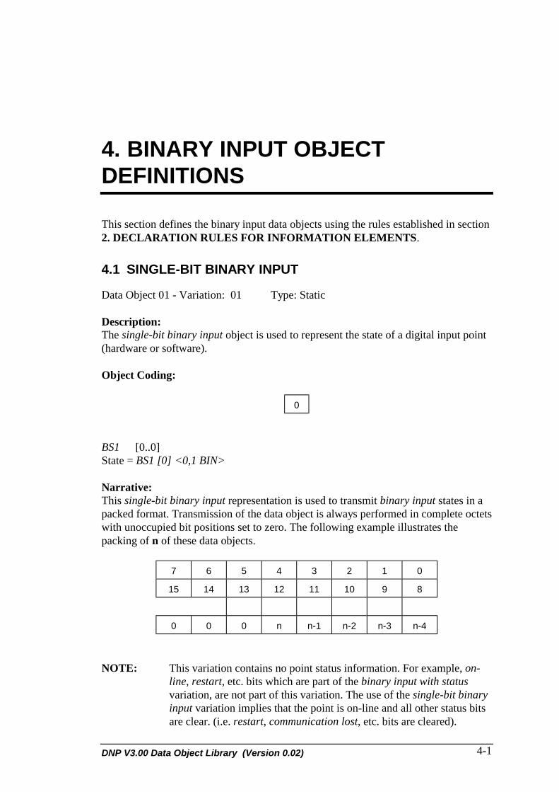
DNP V3.00 Data Object Library (Version 0.02) 4-1
4. BINARY INPUT OBJECTDEFINITIONS
This section defines the binary input data objects using the rules established in section2. DECLARATION RULES FOR INFORMATION ELEMENTS.
4.1 SINGLE-BIT BINARY INPUT
Data Object 01 - Variation: 01 Type: Static
Description:The single-bit binary input object is used to represent the state of a digital input point(hardware or software).
Object Coding:
0
BS1 [0..0]State = BS1 [0] <0,1 BIN>
Narrative:This single-bit binary input representation is used to transmit binary input states in apacked format. Transmission of the data object is always performed in complete octetswith unoccupied bit positions set to zero. The following example illustrates thepacking of n of these data objects.
7 6 5 4 3 2 1 0
15 14 13 12 11 10 9 8
0 0 0 n n-1 n-2 n-3 n-4
NOTE: This variation contains no point status information. For example, on-line, restart, etc. bits which are part of the binary input with statusvariation, are not part of this variation. The use of the single-bit binaryinput variation implies that the point is on-line and all other status bitsare clear. (i.e. restart, communication lost, etc. bits are cleared).

DNP Users Group4-2
4.2 BINARY INPUT WITH STATUS
Data Object 01 - Variation: 02 Type: Static
Description:The binary input with status object is used to represent the state of a digital inputpoint (hardware or software), and also indicates the status of the point as follows:
The on-line bit indicates that the binary input point has been read successfully.If this field is set to off-line, the state of the digital point may not be correct.
The restart bit indicates that the field device that originated the data object iscurrently restarting. This device may be the device reporting this data object.
The communication lost bit indicates that the device reporting this data objecthas lost communication with the originator of the data object.
The remote forced data bit indicates that the state of the binary input has beenforced to its current state at a device other than the end device.
The local forced data bit indicates that the state of the binary input has beenforced to its current state at the end device.
The chatter filter bit indicates that the binary input point has been filtered inorder to remove unneeded transitions in the state of the point.
The state bit indicates the current state of the binary input point.
Object Coding:
7 6 5 4 3 2 1 0
BS8 [0..7]On-line = BS1 [0] <0, off-line; 1, on-line>Restart = BS1 [1] <0, normal; 1, restart>Communication lost = BS1 [2] <0, normal; 1, lost>Remote forced data = BS1 [3] <0, normal; 1, forced>Local forced data = BS1 [4] <0, normal; 1, forced>Chatter filter = BS1 [5] <0, normal; 1, filter on>Reserved = BS1 [6] <0>State = BS1 [7] <0, 1 BIN>
DNP V3.00 Data Object Library (Version 0.02) 4-3
4.3 BINARY INPUT CHANGE WITHOUT TIME
Data Object 02 - Variation: 01 Type: Event
Description:The binary input change without time object is used to represent the changed state of adigital input point (hardware or software) and also indicates the status of the point asfollows:
The on-line bit indicates that the binary input point has been read successfully.If this field is set to off-line, the state of the digital point may not be correct.
The restart bit indicates that the field device that originated the data object hasbeen re-started. This device may be the device reporting this data object.
The communication lost bit indicates that the device reporting this data objecthas lost communication with the originator of the data object.
The remote forced data bit indicates that the state of the binary input has beenforced to its current state at the originating device.
The local forced data bit indicates that the state of the binary input has beenforced to its current state at the device reporting this data object.
The chatter filter bit indicates that the binary input point has been filtered inorder to remove unneeded transitions in the state of the point.
The state bit indicates the current changed state of the binary input point.

DNP Users Group4-4
Object Coding:
7 6 5 4 3 2 1 0
BS8 [0..7]On-line = BS1 [0] <0, off-line; 1, on-line>Restart = BS1 [1] <0, normal; 1, restart>Communication lost = BS1 [2] <0, normal; 1, lost>Remote forced data = BS1 [3] <0, normal; 1, forced>Local forced data = BS1 [4] <0, normal; 1, forced>Chatter filter = BS1 [5] <0, normal; 1, filter on>Reserved = BS1 [6] <0>State = BS1 [7] <0,1 BIN>
Narrative:This object is only reported when the current value is different than the last recordedor measured value. If the chatter filter is on, this object may only be reported when thenew state has remained constant for a certain period of time.
DNP V3.00 Data Object Library (Version 0.02) 4-5
4.4 BINARY INPUT CHANGE WITH TIME
Data Object 02 - Variation: 02 Type: Event
Description:The binary input change with time object is used to represent the changed state of adigital input point (hardware or software) and the time at which the state changed. Italso indicates the status of the point as follows:
The on-line bit indicates that the binary input point has been read successfully.If this field is set to off-line, the state of the digital point may not be correct.
The restart bit indicates that the field device that originated the data object hasbeen re-started. This device may be the device reporting this data object.
The communication lost bit indicates that the device reporting this data objecthas lost communication with the originator of the data object.
The remote forced data bit indicates that the state of the binary input has beenforced to its current state at the originating device.
The local forced data bit indicates that the state of the binary input has beenforced to its current state at the device reporting this data object.
The chatter filter bit indicates that the binary input point has been filtered inorder to remove unneeded transitions in the state of the point.
The state bit indicates the current changed state of the binary input point.
The Time of Occurrence indicates the absolute time at which the telecontrol devicedetected the change of state. The accuracy of this time will depend on the accuracy ofthe individual device.

DNP Users Group4-6
Object Coding:
FLAG
7 6 5 4 3 2 1 0
TIME OF OCCURRENCE
7 6 5 4 3 2 1 0
15 14 13 12 11 10 9 8
23 22 21 20 19 18 17 16
31 30 29 28 27 26 25 24
39 38 37 36 35 34 33 32
47 46 45 44 43 42 41 40
SQ2 {FLAG = BS8 [0..7]Time of Occurrence = UI48 [0..47] <248 -1 ms>}
FLAG ={ BS8 [0..7]On-line = BS1 [0] <0, off-line; 1, on-line>Restart = BS1 [1] <0, normal; 1, restart>Communication lost = BS1 [2] <0, normal; 1, lost>Remote forced data = BS1 [3] <0, normal; 1, forced>Local forced data = BS1 [4] <0, normal; 1, forced>Chatter filter = BS1 [5] <0, normal; 1, filter on>Reserved = BS1 [6] <0>State = BS1 [7] <0,1 BIN>}
Narrative:Time of occurrence is recorded as milliseconds since midnight, January 1st, 1970, atzero hours, zero minutes, seconds, and milliseconds.

DNP V3.00 Data Object Library (Version 0.02) 4-7
4.5 BINARY INPUT CHANGE WITH RELATIVE TIME
Data Object 02 - Variation: 03 Type: Event
Description:The binary input change with relative time object is used to represent the changedstate of a digital input point (hardware or software), and the relative time at which thestate changed. It also indicates the status of the point as follows:
The on-line bit indicates that the binary input point has been read successfully.If this field is set to off-line, the state of the digital point may not be correct.
The restart bit indicates that the field device that originated the data object hasbeen re-started. This device may be the device reporting this data object.
The communication lost bit indicates that the device reporting this data objecthas lost communication with the originator of the data object.
The remote forced data bit indicates that the state of the binary input has beenforced to its current state at the originating device.
The local forced data bit indicates that the state of the binary input has beenforced to its current state at the device reporting this data object.
The chatter filter bit indicates that the binary input point has been filtered inorder to remove unneeded transitions in the state of the point.
The state bit indicates the current changed state of the binary input point.
The MSEC field indicates the relative time at which the telecontrol device detected thechange of state. The accuracy of this time will depend on the accuracy of theindividual device.

DNP Users Group4-8
Object Coding:
FLAG
7 6 5 4 3 2 1 0
MSEC
7 6 5 4 3 2 1 0
15 14 13 12 11 10 9 8
SQ2 {FLAG = BS8 [0..7]MSEC = UI16 [0..15] <0..216-1>
}
FLAG ={ BS8 [0..7]On-line = BS1 [0] <0, off-line; 1, on-line>Restart = BS1 [1] <0, normal; 1, restart>Communication lost = BS1 [2] <0, normal; 1, lost>Remote forced data = BS1 [3] <0, normal; 1, forced>Local forced data = BS1 [4] <0, normal; 1, forced>Chatter filter = BS1 [5] <0, normal; 1, filter on>Reserved = BS1 [6] <0>State = BS1 [7] <0,1 BIN>}
Narrative:This object MUST be preceded by an absolute time object (common time object orCTO) or an unsynchronized CTO in the DNP Application Layer message. The CTO isused as an absolute time base for all following binary input change with relative timeobjects. The relative time in each binary input object is added to the CTO absolutetime to give the absolute time at which the binary input change was detected by thedevice.

DNP V3.00 Data Object Library (Version 0.02) 4-9


DNP V3.00 Data Object Library (Version 0.02) 5-1
5. BINARY OUTPUT OBJECTDEFINITIONS
This section defines the binary output data objects using the rules established insection 2. DECLARATION RULES FOR INFORMATION ELEMENTS.
5.1 BINARY OUTPUT
Data Object 10 - Variation: 01 Type: Static
Description:The binary output object is used to control a digital output point (hardware orsoftware). The state bit indicates the desired logic state of the digital output point.
Object Coding:
0
BS1 [0..0]State = BS1 [0] <0,1 BIN>
Narrative:Transmission of the data object is always pre-formed in complete octets, withunoccupied bit positions set to zero. The following example illustrates the packing ofn of these data objects:
7 6 5 4 3 2 1 0
15 14 13 12 11 10 9 8
0 0 0 n n-1 n-2 n-3 n-4

DNP Users Group5-2
5.2 BINARY OUTPUT STATUS
Data Object 10 - Variation: 02 Type: Static
Description:The binary output status object is used to indicate the current state of a controlleddigital point and the status of that point as follows:
The on-line bit indicates that the device controlling the binary output point isoperating correctly. A binary output command to this point should workcorrectly. If this field is set to off-line, a binary output command to this pointwould be unsuccessful.
The restart bit indicates that the field device that originated the data object hasbeen re-started. This device may be the device reporting this data object.
The communication lost bit indicates that the digital output point could not becontrolled because communications have been lost with the controlled device.
The remote forced data bit indicates that the digital output point has beencontrolled at the originating device and the current state is in the state bit.
The local forced data bit indicates that the digital output point has beencontrolled at this device and the current state is in the state bit.
The state bit indicates the current state of the binary output point.
Object Coding:
7 6 5 4 3 2 1 0
BS8 [0..7]On-line = BS1 [0] <0, off-line; 1, on-line>Restart = BS1 [1] <0, normal; 1, restart>Communication lost = BS1 [2] <0, normal; 1, lost>Remote forced data = BS1 [3] <0, normal; 1, forced>Local forced data = BS1 [4] <0, normal; 1, forced>Reserved = BS1 [5] <0>Reserved = BS1 [6] <0>State = BS1 [7] <0,1 BIN>
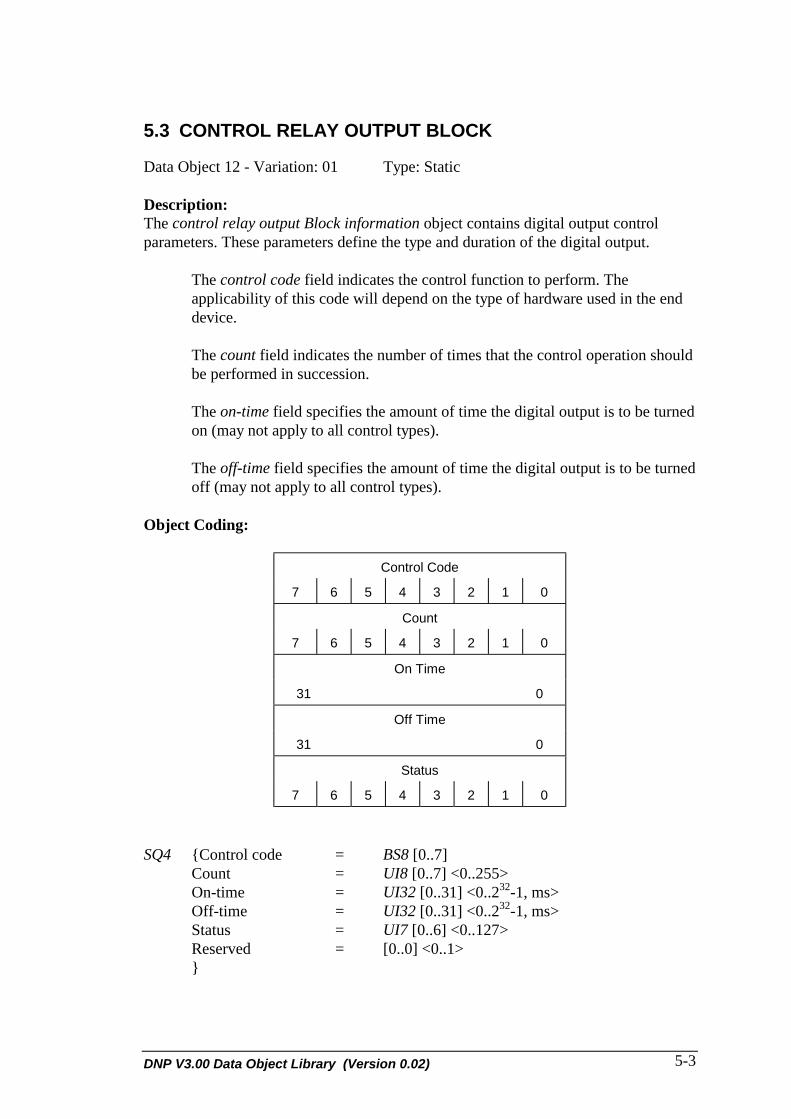
DNP V3.00 Data Object Library (Version 0.02) 5-3
5.3 CONTROL RELAY OUTPUT BLOCK
Data Object 12 - Variation: 01 Type: Static
Description:The control relay output Block information object contains digital output controlparameters. These parameters define the type and duration of the digital output.
The control code field indicates the control function to perform. Theapplicability of this code will depend on the type of hardware used in the enddevice.
The count field indicates the number of times that the control operation shouldbe performed in succession.
The on-time field specifies the amount of time the digital output is to be turnedon (may not apply to all control types).
The off-time field specifies the amount of time the digital output is to be turnedoff (may not apply to all control types).
Object Coding:
Control Code
7 6 5 4 3 2 1 0
Count
7 6 5 4 3 2 1 0
On Time
31 0
Off Time
31 0
Status
7 6 5 4 3 2 1 0
SQ4 {Control code = BS8 [0..7]Count = UI8 [0..7] <0..255>On-time = UI32 [0..31] <0..232-1, ms>Off-time = UI32 [0..31] <0..232-1, ms>Status = UI7 [0..6] <0..127>Reserved = [0..0] <0..1>}
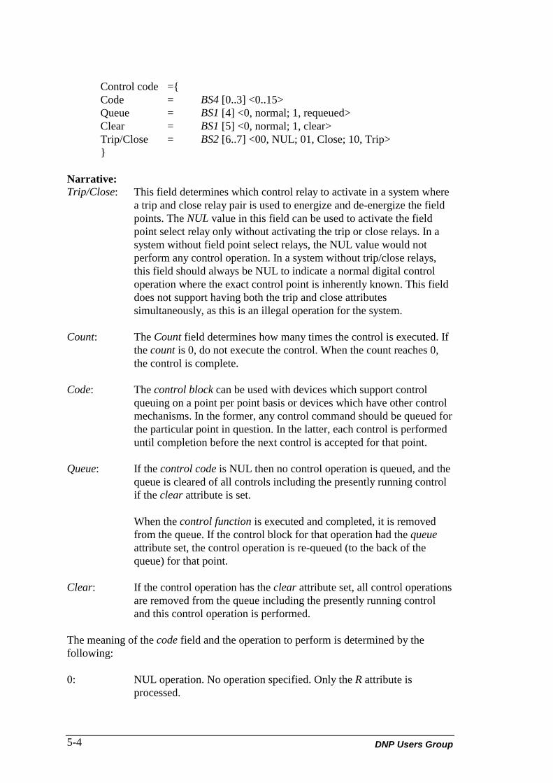
DNP Users Group5-4
Control code ={Code = BS4 [0..3] <0..15>Queue = BS1 [4] <0, normal; 1, requeued>Clear = BS1 [5] <0, normal; 1, clear>Trip/Close = BS2 [6..7] <00, NUL; 01, Close; 10, Trip>}
Narrative:Trip/Close: This field determines which control relay to activate in a system where
a trip and close relay pair is used to energize and de-energize the fieldpoints. The NUL value in this field can be used to activate the fieldpoint select relay only without activating the trip or close relays. In asystem without field point select relays, the NUL value would notperform any control operation. In a system without trip/close relays,this field should always be NUL to indicate a normal digital controloperation where the exact control point is inherently known. This fielddoes not support having both the trip and close attributessimultaneously, as this is an illegal operation for the system.
Count: The Count field determines how many times the control is executed. Ifthe count is 0, do not execute the control. When the count reaches 0,the control is complete.
Code: The control block can be used with devices which support controlqueuing on a point per point basis or devices which have other controlmechanisms. In the former, any control command should be queued forthe particular point in question. In the latter, each control is performeduntil completion before the next control is accepted for that point.
Queue: If the control code is NUL then no control operation is queued, and thequeue is cleared of all controls including the presently running controlif the clear attribute is set.
When the control function is executed and completed, it is removedfrom the queue. If the control block for that operation had the queueattribute set, the control operation is re-queued (to the back of thequeue) for that point.
Clear: If the control operation has the clear attribute set, all control operationsare removed from the queue including the presently running controland this control operation is performed.
The meaning of the code field and the operation to perform is determined by thefollowing:
0: NUL operation. No operation specified. Only the R attribute isprocessed.

DNP V3.00 Data Object Library (Version 0.02) 5-5
1: Pulse On - The point(s) is turned on for the specified on-time, turnedoff for the specified off-time and left in the off state.
2: Pulse Off - The point(s) is turned off for the specified off-time, thenturned on for the specified on-time and left in the on state.
3: Latch On - This latches the point(s) on.
4: Latch Off - This latches the point(s) off.
5 - 15: Undefined.
Queue: Place operation at the back of the control queue when complete.
Clear: Cancel currently running operation and remove queued operations onaffected points immediately before activating this new operation (if notNUL).
The reserved bit of the control point after the operation can bedetermined if the control output is on.
The success or failure of the requested control operation is returned inthe status field. The meaning of this field is determined as follows:
0: Request accepted, initiated, or queued.
1: Request not accepted as the operate message was received afterthe arm timer timed out. The arm timer was started when theselect operation for the same point was received.
2: No previous matching select message (i.e. an operate messagewas sent to activate a control point that was not previouslyarmed with the select message.
3: Request not accepted as there were formatting errors in thecontrol request (either select, operate, or direct operate).
4: Control operation not supported for this point.
5: Request not accepted, as the control queue is full or the point isalready active.
6: Request not accepted because of control hardware problems.
7 - 127:Undefined.

DNP Users Group5-6
5.4 PATTERN CONTROL BLOCK
Data Object 12 - Variation: 02 Type: Static
Description:The pattern control block (PCB) object contains digital output control parameters forpattern type controls. These parameters define the type and duration of the digitaloutput for each of the affected points. The PCB object defines all the parameters forthe subsequent pattern mask objects which follow this object in the message. Theseparameters contained in the PCB influence all the pattern mask object(s) thatimmediately follow the PCB object, until the next PCB in the message.
The combination of this object and the pattern mask objects that follow will specify anumber (0 or more) of control operations to perform (i.e. the same operation ondifferent points). All these controls must be performed in parallel. The meaning of allfields, attributes, and parameters are identical to the control relay output block exceptthat the queuing attributes are not valid. This is, the pattern control is not meant to bere-queued.
Object Coding:
Control Code
7 6 5 4 3 2 1 0
Count
7 6 5 4 3 2 1 0
On Time
31 0
Off Time
31 0
Status
7 6 5 4 3 2 1 0

DNP V3.00 Data Object Library (Version 0.02) 5-7
5.5 PATTERN MASK
Data Object 12 - Variation: 03 Type: Static
Description:The pattern mask object is used to select from a range of possible control points thathave to be executed in parallel.
This object is used in conjunction with the PCB object to specify both the control pointsto operate and the parameters that determine the control operation.
If the mask bit is set to active, then the parameters specified in the preceding PCB areapplied to a specified point for each pattern mask object and a control operation isgenerated for the point.
Object Coding:
M
BS1 [0..0]Mask = BS1 [0] <0, inactive; 1, active>
Narrative:This single-bit pattern mask is typically sent in groups. Transmission of the data objectis always performed in complete octets with unoccupied bit positions set to zero. Thefollowing example illustrates the packing of n of these data objects.
7 6 5 4 3 2 1 0
15 14 13 12 11 10 9 8
0 0 0 n n-1 n-2 n-3 n-4

DNP V3.00 Data Object Library (Version 0.02) 6-1
6. COUNTER OBJECT DEFINITIONS
This section defines the counter data objects using the rules established in section 2..DECLARATION RULES FOR INFORMATION ELEMENTS.
6.1 32-BIT BINARY COUNTER
Data Object 20 - Variation: 01 Type: Static
Description:The 32-bit binary counter represents an accumulated value. This can be accumulatedpulses or transitions from a hardware or software point.
The value field shows the current value of the counter at the time of reporting or lastreported value from the originating device. This value increments indefinitely until acounter clear operation is performed in which case the value is reset to 0.
The flag field has the same meaning as in previous objects, with the following inclusion:
• When set, the roll-over bit indicates that the accumulated value has exceeded the lastreported recordable value (232-1). The counter value has been reset to 0 upon the roll-over and counting has resumed as normal. This bit is cleared when the counter value(plus the roll-over state) is reported.

DNP Users Group6-2
Object Coding:
FLAG
7 6 5 4 3 2 1 0
Value
31 0
SQ2 {FLAG = BS8 [0..7]Value = UI32 [0..31] <0..232-1>}
FLAG ={On-line = BS1 [0] <0, off-line; 1, on-line>Restart = BS1 [1] <0, normal; 1, restart>Communication lost = BS1 [2] <0, normal; 1, lost>Remote forced data = BS1 [3] <0, normal; 1, forced>Local forced data = BS1 [4] <0, normal; 1, forced>Roll-over = BS1 [4] <0, normal; 1, roll-over>Roll-over = BS1 [5] <0, normal; 1, roll-over>Reserved = BS1 [6] <0>Reserved = BS1 [7] <0>}

DNP V3.00 Data Object Library (Version 0.02) 6-3
6.2 16-BIT BINARY COUNTER
Data Object 20 - Variation: 02 Type: Static
Description:The 16-bit binary counter represents an accumulated value. This can be accumulatedpulses or transitions from a hardware or software point.
The value field shows the current value of the counter at the time of reporting or lastreported value from the originating device. This value increments indefinitely until acounter clear operation is performed in which case the value is reset to 0.
The flag field has the same meaning as in previous objects, with the following inclusion:
• When set, the roll-over bit indicates that the accumulated value has exceeded themaximum possible recordable value (216-1). The counter value has been reset to 0upon roll-over, and counting has resumed as normal. This bit is cleared when thecounter value (plus the roll-over state) is reported.
Object Coding:
FLAG
7 6 5 4 3 2 1 0
Value
15 0
SQ2 {FLAG = BS8 [0..7]Value = UI16 [0..15] <0..216-1>}
FLAG ={On-line = BS1 [0] <0, off-line; 1, on-line>Restart = BS1 [1] <0, normal; 1, restart>Communication lost = BS1 [2] <0, normal; 1, lost>Remote forced data = BS1 [3] <0, normal; 1, forced>Local forced data = BS1 [4] <0, normal; 1, forced>Roll-over = BS1 [4] <0, normal; 1, roll-over>Roll-over = BS1 [5] <0, normal; 1, roll-over>Reserved = BS1 [6] <0>Reserved = BS1 [7] <0>}

DNP Users Group6-4
6.3 32-BIT DELTA COUNTER
Data Object 20 - Variation: 03 Type: Static
Description:The 32-bit delta counter represents a value that has accumulated since the last value wasreported. This can be accumulated pulses or transitions from a hardware or softwarepoint.
The value field shows the current value of the counter at the time of reporting or lastreported value from the originating device. This value increments until it is reported atwhich point it is reset to 0.
The flag field has the same meaning as in previous objects, with the following inclusion:
• When set, the roll-over bit indicates that the accumulated value has exceeded themaximum possible recordable value (232-1). The counter value has been reset to 0upon roll-over, and counting has resumed as normal. This bit is cleared when thecounter value (plus the roll-over state) is reported.
Object Coding:
FLAG
7 6 5 4 3 2 1 0
Value
31 0
SQ2 {FLAG = BS8 [0..7]Value = UI32 [0..31] <0..232-1>}
FLAG ={On-line = BS1 [0] <0, off-line; 1, on-line>Restart = BS1 [1] <0, normal; 1, restart>Communication lost = BS1 [2] <0, normal; 1, lost>Remote forced data = BS1 [3] <0, normal; 1, forced>Local forced data = BS1 [4] <0, normal; 1, forced>Roll-over = BS1 [4] <0, normal; 1, roll-over>Roll-over = BS1 [5] <0, normal; 1, roll-over>Reserved = BS1 [6] <0>Reserved = BS1 [7] <0>}

DNP V3.00 Data Object Library (Version 0.02) 6-5
6.4 16-BIT DELTA COUNTER
Data Object 20 - Variation: 04 Type: Static
Description:The 16-bit delta counter represents a value that has accumulated since the last value wasreported. This can be accumulated pulses or transitions from a hardware or softwarepoint.
The value field shows the current value of the counter at the time of reporting or lastreported value from the originating device. This value increments until it is reported atwhich point it is reset to 0.
The flag field has the same meaning as in previous objects, with the following inclusion:
• When set, the roll-over bit indicates that the accumulated value has exceeded themaximum possible recordable value (216-1). The counter value has been reset to 0upon the roll-over and counting has resumed as normal. This bit is cleared when thecounter value (plus the roll-over state) is reported.
Object Coding:
FLAG
7 6 5 4 3 2 1 0
Value
15 0
SQ2 {FLAG = BS8 [0..7]Value = UI16 [0..15] <0..216-1>}
FLAG ={On-line = BS1 [0] <0, off-line; 1, on-line>Restart = BS1 [1] <0, normal; 1, restart>Communication lost = BS1 [2] <0, normal; 1, lost>Remote forced data = BS1 [3] <0, normal; 1, forced>Local forced data = BS1 [4] <0, normal; 1, forced>Roll-over = BS1 [4] <0, normal; 1, roll-over>Roll-over = BS1 [5] <0, normal; 1, roll-over>Reserved = BS1 [6] <0>Reserved = BS1 [7] <0>}

DNP Users Group6-6
6.5 32-BIT COUNTER WITHOUT FLAG
Data Object 20 - Variation: 05 Type: Static
Description:The 32-bit binary counter represents an accumulated value. This can be accumulatedpulses or transitions from a hardware or software point.
The value field shows the current value of the counter at the time of reporting or lastreported value from the originating device. This value increments indefinitely until acounter clear operation is performed in which case the value is reset to 0.
Object Coding:
Value
31 0
SQ2 {Value = UI32 [0..31] <0..232-1>}
NOTE: The use of this variation implies that the input point is on-line and thatall other flag bits are normal (i.e. this variation implies that flag = 1).

DNP V3.00 Data Object Library (Version 0.02) 6-7
6.6 16-BIT COUNTER WITHOUT FLAG
Data Object 20 - Variation: 06 Type: Static
Description:The 16-bit binary counter represents an accumulated value. This can be accumulatedpulses or transitions from a hardware or software point.
The value field shows the current value of the counter at the time of reporting or lastreported value from the originating device. This value increments indefinitely until acounter clear operation is performed in which case the value is reset to 0.
Object Coding:
Value
15 0
SQ2 {Value = UI16 [0..15] <0..216-1>}
NOTE: The use of this variation implies that the input point is on-line and thatall other flag bits are normal (i.e. this variation implies that flag = 1).
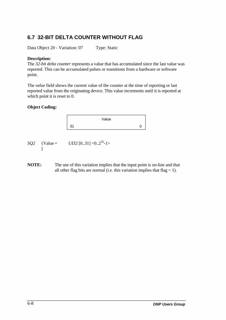
DNP Users Group6-8
6.7 32-BIT DELTA COUNTER WITHOUT FLAG
Data Object 20 - Variation: 07 Type: Static
Description:The 32-bit delta counter represents a value that has accumulated since the last value wasreported. This can be accumulated pulses or transitions from a hardware or softwarepoint.
The value field shows the current value of the counter at the time of reporting or lastreported value from the originating device. This value increments until it is reported atwhich point it is reset to 0.
Object Coding:
Value
31 0
SQ2 {Value = UI32 [0..31] <0..232-1>}
NOTE: The use of this variation implies that the input point is on-line and thatall other flag bits are normal (i.e. this variation implies that flag = 1).
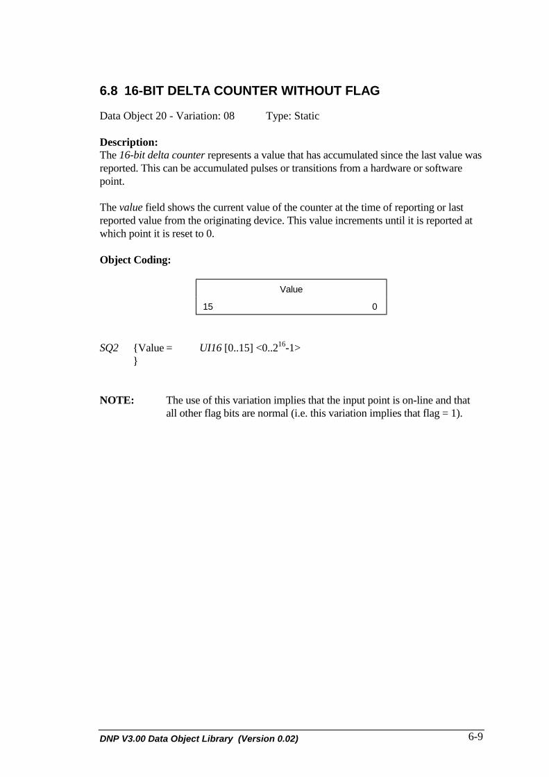
DNP V3.00 Data Object Library (Version 0.02) 6-9
6.8 16-BIT DELTA COUNTER WITHOUT FLAG
Data Object 20 - Variation: 08 Type: Static
Description:The 16-bit delta counter represents a value that has accumulated since the last value wasreported. This can be accumulated pulses or transitions from a hardware or softwarepoint.
The value field shows the current value of the counter at the time of reporting or lastreported value from the originating device. This value increments until it is reported atwhich point it is reset to 0.
Object Coding:
Value
15 0
SQ2 {Value = UI16 [0..15] <0..216-1>}
NOTE: The use of this variation implies that the input point is on-line and thatall other flag bits are normal (i.e. this variation implies that flag = 1).

DNP Users Group6-10
6.9 32-BIT FROZEN COUNTER
Data Object 21 - Variation: 01 Type: Frozen Static
Description:The 32-bit frozen counter is a compound information object which contains informationabout a counter which was previously frozen.
The frozen value shows the value of the counter when the last counter freeze wasperformed at the originating device.
The flag field has the same meaning as in previous objects.
Object Coding:
FLAG
7 6 5 4 3 2 1 0
Frozen Value
31 0
SQ2 {FLAG = BS8 [0..7]Frozen Value = UI32 [0..31] <0..232-1>
FLAG ={On-line = BS1 [0] <0, off-line; 1, on-line>Restart = BS1 [1] <0, normal; 1, restart>Communication lost = BS1 [2] <0, normal; 1, lost>Remote forced data = BS1 [3] <0, normal; 1, forced>Local forced data = BS1 [4] <0, normal; 1, forced>Roll-over = BS1 [4] <0, normal; 1, roll-over>Roll-over = BS1 [5] <0, normal; 1, roll-over>Reserved = BS1 [6] <0>Reserved = BS1 [7] <0>}

DNP V3.00 Data Object Library (Version 0.02) 6-11
6.10 16-BIT FROZEN COUNTER
Data Object 21 - Variation: 02 Type: Frozen Static
Description:The 16-bit frozen counter is a compound information object that contains informationabout a counter that was previously frozen. The counter accumulates pulses ortransitions from a hardware or software point.
The frozen value shows the value of the counter when the last counter freeze wasperformed at the originating device.
The flag field has the same meaning as in previous objects.
Object Coding:
FLAG
7 6 5 4 3 2 1 0
Frozen Value
15 0
SQ2 {FLAG = BS8 [0..7]Frozen Value = UI16 [0..15] <0..216-1>}
FLAG ={On-line = BS1 [0] <0, off-line; 1, on-line>Restart = BS1 [1] <0, normal; 1, restart>Communication lost = BS1 [2] <0, normal; 1, lost>Remote forced data = BS1 [3] <0, normal; 1, forced>Local forced data = BS1 [4] <0, normal; 1, forced>Roll-over = BS1 [4] <0, normal; 1, roll-over>Roll-over = BS1 [5] <0, normal; 1, roll-over>Reserved = BS1 [6] <0>Reserved = BS1 [7] <0>}

DNP Users Group6-12
6.11 32-BIT FROZEN DELTA COUNTER
Data Object 21 - Variation: 03 Type: Frozen Static
Description:The 32-bit frozen delta counter represents a frozen value that has accumulated since thelast value was reported. This can be accumulated pulses or transitions from a hardwareor software point.
The frozen value shows the value of the counter when the last counter freeze wasperformed at the originating device.
The flag field has the same meaning as in previous objects.
Object Coding:
FLAG
7 6 5 4 3 2 1 0
Frozen Value
31 0
SQ2 {FLAG = BS8 [0..7]Frozen Value = UI32 [0..31] <0..232-1>
FLAG ={On-line = BS1 [0] <0, off-line; 1, on-line>Restart = BS1 [1] <0, normal; 1, restart>Communication lost = BS1 [2] <0, normal; 1, lost>Remote forced data = BS1 [3] <0, normal; 1, forced>Local forced data = BS1 [4] <0, normal; 1, forced>Roll-over = BS1 [4] <0, normal; 1, roll-over>Roll-over = BS1 [5] <0, normal; 1, roll-over>Reserved = BS1 [6] <0>Reserved = BS1 [7] <0>}

DNP V3.00 Data Object Library (Version 0.02) 6-13
6.12 16-BIT FROZEN DELTA COUNTER
Data Object 21 - Variation: 04 Type: Frozen Static
Description:
The 16-bit frozen delta counter represents a frozen value that has accumulated since thelast value was reported. This can be accumulated pulses or transitions from a hardwareor software point.
The frozen value shows the value of the counter when the last counter freeze wasperformed at the originating device.
The flag field has the same meaning as in previous objects.
Object Coding:
FLAG
7 6 5 4 3 2 1 0
Frozen Value
15 0
SQ2 {FLAG = BS8 [0..7]Frozen Value = UI16 [0..15] <0..216-1>}
FLAG ={On-line = BS1 [0] <0, off-line; 1, on-line>Restart = BS1 [1] <0, normal; 1, restart>Communication lost = BS1 [2] <0, normal; 1, lost>Remote forced data = BS1 [3] <0, normal; 1, forced>Local forced data = BS1 [4] <0, normal; 1, forced>Roll-over = BS1 [4] <0, normal; 1, roll-over>Roll-over = BS1 [5] <0, normal; 1, roll-over>Reserved = BS1 [6] <0>Reserved = BS1 [7] <0>}

DNP Users Group6-14
6.13 32-BIT FROZEN COUNTER WITH TIME OF FREEZE
Data Object 21 - Variation: 05 Type: Frozen Static
Description:The 32-bit frozen counter with time of freeze is a compound information object whichcontains information about a counter which was previously frozen. The counteraccumulates pulses or transitions from a hardware or software point.
The frozen value shows the value of the counter when the time was time of freeze.
The time of freeze field contains a time that this object was frozen. This timecorresponds to the frozen value so that the current value of this object at time of freeze isfrozen value.
The flag field has the same meaning as in previous objects.
Object Coding:
FLAG
7 6 5 4 3 2 1 0
Frozen Value
31 0
Time of Freeze
47 0
SQ4 {FLAG = BS8 [0..7]Frozen value = UI32 [0..31] <0..232-1>Time of Freeze = UI48 [0..47] <248 -1 ms>}
FLAG ={On-line = BS1 [0] <0, off-line; 1, on-line>Restart = BS1 [1] <0, normal; 1, restart>Communication lost = BS1 [2] <0, normal; 1, lost>Remote forced data = BS1 [3] <0, normal; 1, forced>Local forced data = BS1 [4] <0, normal; 1, forced>Roll-over = BS1[4] <0, normal; 1, roll-over>Roll-over = BS1 [5] <0, normal; 1, roll-over>Reserved = BS1 [6] <0>Reserved = BS1 [7] <0>}
Narrative:Time of freeze is recorded as milliseconds since midnight, January 1st, 1970, at zerohours, zero minutes, seconds, and milliseconds.

DNP V3.00 Data Object Library (Version 0.02) 6-15
6.14 16-BIT FROZEN COUNTER WITH TIME OF FREEZE
Data Object 21 - Variation: 06 Type: Frozen Static
Description:The 16-bit frozen counter with time of freeze is a compound information object whichcontains information about a counter which was previously frozen. The counteraccumulates pulses or transitions from a hardware or software point.
The frozen value shows the value of the counter when the time was time of freeze.
The time of freeze field contains a time that this object was frozen. This timecorresponds to the frozen value so that the current value of this object at time of freeze isfrozen value.
The flag field has the same meaning as in previous objects.
Object Coding:
FLAG
7 6 5 4 3 2 1 0
Frozen Value
15 0
Time of Freeze
47 0
SQ4 {FLAG = BS8 [0..7]Frozen value = UI16 [0..15] <0..216-1>Time of Freeze = UI48 [0..47] <248 -1 ms>}
FLAG ={On-line = BS1 [0] <0, off-line; 1, on-line>Restart = BS1 [1] <0, normal; 1, restart>Communication lost = BS1 [2] <0, normal; 1, lost>Remote forced data = BS1 [3] <0, normal; 1, forced>Local forced data = BS1 [4] <0, normal; 1, forced>Roll-over = BS1[4] <0, normal; 1, roll-over>Roll-over = BS1 [5] <0, normal; 1, roll-over>Reserved = BS1 [6] <0>Reserved = BS1 [7] <0>}
Narrative:Time of freeze is recorded as milliseconds since midnight, January 1st, 1970, at zerohours, zero minutes, seconds, and milliseconds.

DNP Users Group6-16
6.15 32-BIT FROZEN DELTA COUNTER WITH TIME OFFREEZE
Data Object 21 - Variation: 07 Type: Frozen Static
Description:The 32-bit frozen delta counter with time of freeze represents a frozen value that hasaccumulated since the last value was reported. This can be accumulated pulses ortransitions from a hardware or software point.
The frozen value shows the value of the counter when the time was time of freeze.
The time of freeze field contains a time that this object was frozen. This timecorresponds to the frozen value so that the current value of this object at time of freeze isfrozen value.
The flag field has the same meaning as in previous objects.
Object Coding:
FLAG
7 6 5 4 3 2 1 0
Frozen value
31 0
Time of Freeze
47 0
SQ4 {FLAG = BS8 [0..7]Frozen value = UI32 [0..31] <0..232-1>Time of Freeze = UI48 [0..47] <248 -1 ms>}
FLAG ={On-line = BS1 [0] <0, off-line; 1, on-line>Restart = BS1 [1] <0, normal; 1, restart>Communication lost = BS1 [2] <0, normal; 1, lost>Remote forced data = BS1 [3] <0, normal; 1, forced>Local forced data = BS1 [4] <0, normal; 1, forced>Roll-over = BS1 [4] <0, normal; 1, roll-over>Roll-over = BS1 [5] <0, normal; 1, roll-over>Reserved = BS1 [6] <0>Reserved = BS1 [7] <0>}

DNP V3.00 Data Object Library (Version 0.02) 6-17
Narrative:Time of freeze is recorded as milliseconds since midnight, January 1st, 1970, at zerohours, zero minutes, seconds, and milliseconds.

DNP Users Group6-18
6.16 16-BIT FROZEN DELTA COUNTER WITH TIME OFFREEZE
Data Object 21 - Variation: 08 Type: Frozen Static
Description:The 16-bit frozen delta counter with time of freeze represents a frozen value that hasaccumulated since the last value was reported. This can be accumulated pulses ortransitions from a hardware or software point.
The frozen value shows the value of the counter when the time was time of freeze.
The time of freeze field contains a time that this object was frozen. This timecorresponds to the frozen value so that the current value of this object at time of freeze isfrozen value.
The flag field has the same meaning as in previous objects.
Object Coding:
FLAG
7 6 5 4 3 2 1 0
Frozen value
15 0
Time of Freeze
47 0
SQ4 {FLAG = BS8 [0..7]Frozen value = UI16 [0..15] <0..216-1>Time of Freeze = UI48 [0..47] <248 -1 ms>}
FLAG ={On-line = BS1 [0] <0, off-line; 1, on-line>Restart = BS1 [1] <0, normal; 1, restart>Communication lost = BS1 [2] <0, normal; 1, lost>Remote forced data = BS1 [3] <0, normal; 1, forced>Local forced data = BS1 [4] <0, normal; 1, forced>Roll-over = BS1 [4] <0, normal; 1, roll-over>Roll-over = BS1 [5] <0, normal; 1, roll-over>Reserved = BS1 [6] <0>Reserved = BS1 [7] <0>}

DNP V3.00 Data Object Library (Version 0.02) 6-19
Narrative:Time of freeze is recorded as milliseconds since midnight, January 1st, 1970, at zerohours, zero minutes, seconds, and milliseconds.

DNP Users Group6-20
6.17 32-BIT FROZEN COUNTER WITHOUT FLAG
Data Object 21 - Variation: 09 Type: Frozen Static
Description:The 32-bit frozen counter is a compound information object which contains informationabout a counter which was previously frozen.
The frozen value shows the value of the counter when the last counter freeze wasperformed at the originating device.
Object Coding:
Frozen Value
31 0
SQ2 {Frozen Value = UI32 [0..31] <0..232-1>}
NOTE: The use of this variation implies that the input point is on-line and thatall other flag bits are normal (i.e. this variation implies that flag = 1).

DNP V3.00 Data Object Library (Version 0.02) 6-21
6.18 16-BIT FROZEN COUNTER WITHOUT FLAG
Data Object 21 - Variation: 10 Type: Frozen Static
Description:The 16-bit frozen counter is a compound information object which contains informationabout a counter which was previously frozen. The counter accumulates pulses ortransitions from a hardware or software point.
The frozen value shows the value of the counter when the last counter freeze wasperformed at the originating device.
Object Coding:
Frozen Value
15 0
SQ2 {Frozen Value = UI16 [0..15] <0..216-1>}
NOTE: The use of this variation implies that the input point is on-line and thatall other flag bits are normal (i.e. this variation implies that flag = 1).

DNP Users Group6-22
6.19 32-BIT FROZEN DELTA COUNTER WITHOUT FLAG
Data Object 21 - Variation: 11 Type: Frozen Static
Description:The 32-bit frozen delta counter represents a frozen value that has accumulated since thelast value was reported. This can be accumulated pulses or transitions from a hardwareor software point.
The frozen value shows the value of the counter when the last counter freeze wasperformed at the originating device.
Object Coding:
Frozen Value
31 0
SQ2 {Frozen Value = UI32 [0..31] <0..232-1>}
NOTE: The use of this variation implies that the input point is on-line and thatall other flag bits are normal (i.e. this variation implies that flag = 1).

DNP V3.00 Data Object Library (Version 0.02) 6-23
6.20 16-BIT FROZEN DELTA COUNTER WITHOUT FLAG
Data Object 21 - Variation: 12 Type: Frozen Static
Description:The 16-bit frozen delta counter represents a frozen value that has accumulated since thelast value was reported. This can be accumulated pulses or transitions from a hardwareor software point.
The frozen value shows the value of the counter when the last counter freeze wasperformed at the originating device.
Object Coding:
Frozen Value
15 0
SQ2 {Frozen Value = UI16 [0..15] <0..216-1>}
NOTE: The use of this variation implies that the input point is on-line and thatall other flag bits are normal (i.e. this variation implies that flag = 1).

DNP Users Group6-24
6.21 32-BIT COUNTER CHANGE EVENT WITHOUT TIME
Data Object 22 - Variation: 01 Type: Event
Description:The 32-bit counter change event without time represents a counter value that, since lastreported, has exceeded a configured count. This can be accumulated pulses or transitionsfrom a hardware or software point.
The current value field shows the value of the counter which generated the event.
The flag field has the same meaning as in previous objects.
Object Coding:
FLAG
7 6 5 4 3 2 1 0
Current value
31 0
SQ4 {FLAG = BS8 [0..7]Current value = UI32 [0..31] <0..232-1>}
FLAG ={On-line = BS1 [0] <0, off-line; 1, on-line>Restart = BS1 [1] <0, normal; 1, restart>Communication lost = BS1 [2] <0, normal; 1, lost>Remote forced data = BS1 [3] <0, normal; 1, forced>Local forced data = BS1 [4] <0, normal; 1, forced>Roll-over = BS1 [4] <0, normal; 1, roll-over>Roll-over = BS1 [5] <0, normal; 1, roll-over>Reserved = BS1 [6] <0>Reserved = BS1 [7] <0>}

DNP V3.00 Data Object Library (Version 0.02) 6-25
6.22 16-BIT COUNTER CHANGE EVENT WITHOUT TIME
Data Object 22 - Variation: 02 Type: Event
Description:The 16-bit counter change event without time represents a counter value that hasexceeded a configured deadband. This can be accumulated pulses or transitions from ahardware or software point.
The current value field shows the value of the counter which generated the event.
The flag field has the same meaning as in previous objects.
Object Coding:
FLAG
7 6 5 4 3 2 1 0
Current value
15 0
SQ4 {FLAG = BS8 [0..7]Current value = UI16 [0..15] <0..216-1>}
FLAG ={On-line = BS1 [0] <0, off-line; 1, on-line>Restart = BS1 [1] <0, normal; 1, restart>Communication lost = BS1 [2] <0, normal; 1, lost>Remote forced data = BS1 [3] <0, normal; 1, forced>Local forced data = BS1 [4] <0, normal; 1, forced>Roll-over = BS1 [4] <0, normal; 1, roll-over>Roll-over = BS1 [5] <0, normal; 1, roll-over>Reserved = BS1 [6] <0>Reserved = BS1 [7] <0>}

DNP Users Group6-26
6.23 32-BIT DELTA COUNTER CHANGE EVENT WITHOUTTIME
Data Object 22 - Variation: 03 Type: Event
Description:The 32-bit delta counter change event without time represents a delta counter value thathas exceeded a configured deadband. This can be accumulated pulses or transitions froma hardware or software point.
The delta value field shows the change of the counter which generated the event.
The flag field has the same meaning as in previous objects.
Object Coding:
FLAG
7 6 5 4 3 2 1 0
Delta value
31 0
SQ4 {FLAG = BS8 [0..7]Current value = UI32 [0..31] <0..232-1>}
FLAG ={On-line = BS1 [0] <0, off-line; 1, on-line>Restart = BS1 [1] <0, normal; 1, restart>Communication lost = BS1 [2] <0, normal; 1, lost>Remote forced data = BS1 [3] <0, normal; 1, forced>Local forced data = BS1 [4] <0, normal; 1, forced>Roll-over = BS1 [4] <0, normal; 1, roll-over>Roll-over = BS1 [5] <0, normal; 1, roll-over>Reserved = BS1 [6] <0>Reserved = BS1 [7] <0>}

DNP V3.00 Data Object Library (Version 0.02) 6-27
6.24 16-BIT DELTA COUNTER CHANGE EVENT WITHOUTTIME
Data Object 22 - Variation: 04 Type: Event
Description:The 16-bit delta counter change event without time represents a delta counter value thathas exceeded a configured deadband. This can be accumulated pulses or transitions froma hardware or software point.
The delta value field shows the change of the counter which generated the event.
The flag field has the same meaning as in previous objects.
Object Coding:
FLAG
7 6 5 4 3 2 1 0
Delta value
15 0
SQ4 {FLAG = BS8 [0..7]Current value = UI32 [0..16] <0..216-1>}
FLAG ={On-line = BS1 [0] <0, off-line; 1, on-line>Restart = BS1 [1] <0, normal; 1, restart>Communication lost = BS1 [2] <0, normal; 1, lost>Remote forced data = BS1 [3] <0, normal; 1, forced>Local forced data = BS1 [4] <0, normal; 1, forced>Roll-over = BS1 [4] <0, normal; 1, roll-over>Roll-over = BS1 [5] <0, normal; 1, roll-over>Reserved = BS1 [6] <0>Reserved = BS1 [7] <0>}

DNP Users Group6-28
6.25 32-BIT COUNTER CHANGE EVENT WITH TIME
Data Object 22 - Variation: 05 Type: Event
Description:The 32-bit counter change event with time represents a counter value that has exceededa configured deadband. This can be accumulated pulses or transitions from a hardwareor software point.
The value field shows the value of the counter which generated the event.
The Time field contains the time that processing generated the event.
The flag field has the same meaning as in previous objects.
Object Coding:
FLAG
7 6 5 4 3 2 1 0
Value
31 0
Time
47 0
SQ4 {FLAG = BS8 [0..7]Value = UI32 [0..31] <0..232-1>Time = UI48 [0..47] <248 -1 ms>}
FLAG ={On-line = BS1 [0] <0, off-line; 1, on-line>Restart = BS1 [1] <0, normal; 1, restart>Communication lost = BS1 [2] <0, normal; 1, lost>Remote forced data = BS1 [3] <0, normal; 1, forced>Local forced data = BS1 [4] <0, normal; 1, forced>Roll-over = BS1 [4] <0, normal; 1, roll-over>Roll-over = BS1 [5] <0, normal; 1, roll-over>Reserved = BS1 [6] <0>Reserved = BS1 [7] <0>}
Narrative:Time is recorded as milliseconds since midnight, January 1st, 1970, at zero hours, zerominutes, seconds, and milliseconds.

DNP V3.00 Data Object Library (Version 0.02) 6-29
6.26 16-BIT COUNTER CHANGE EVENT WITH TIME
Data Object 22 - Variation: 06 Type: Event
Description:The 16-bit counter change event with time represents a counter value that has exceededa configured deadband. This can be accumulated pulses or transitions from a hardwareor software point.
The value field shows the value of the counter which generated the event.
The time field contains the time that processing generated the event.
The flag field has the same meaning as in previous objects.
Object Coding:
FLAG
7 6 5 4 3 2 1 0
Value
15 0
Time
47 0
SQ4 {FLAG = BS8 [0..7]Value = UI16 [0..15] <0..216-1>Time = UI48 [0..47] <248 -1 ms>}
FLAG ={On-line = BS1 [0] <0, off-line; 1, on-line>Restart = BS1 [1] <0, normal; 1, restart>Communication lost = BS1 [2] <0, normal; 1, lost>Remote forced data = BS1 [3] <0, normal; 1, forced>Local forced data = BS1 [4] <0, normal; 1, forced>Roll-over = BS1 [4] <0, normal; 1, roll-over>Roll-over = BS1 [5] <0, normal; 1, roll-over>Reserved = BS1 [6] <0>Reserved = BS1 [7] <0>}
Narrative:Time is recorded as milliseconds since midnight, January 1st, 1970, at zero hours, zerominutes, seconds, and milliseconds.

DNP Users Group6-30
6.27 32-BIT DELTA COUNTER CHANGE EVENT WITH TIME
Data Object 22 - Variation: 07 Type: Event
Description:The 32-bit delta counter change event with time represents a delta counter value that hasexceeded a configured deadband. This can be accumulated pulses or transitions from ahardware or software point.
The value field shows the value of the change which generated the event.
The time contains the time that processing generated the event.
The flag field has the same meaning as in previous objects.
Object Coding:
FLAG
7 6 5 4 3 2 1 0
Value
31 0
Time
47 0
SQ4 {FLAG = BS8 [0..7]Value = UI32 [0..31] <0..232-1>Time = UI48 [0..47] <248 -1 ms>}
FLAG ={On-line = BS1 [0] <0, off-line; 1, on-line>Restart = BS1 [1] <0, normal; 1, restart>Communication lost = BS1 [2] <0, normal; 1, lost>Remote forced data = BS1 [3] <0, normal; 1, forced>Local forced data = BS1 [4] <0, normal; 1, forced>Roll-over = BS1 [4] <0, normal; 1, roll-over>Roll-over = BS1 [5] <0, normal; 1, roll-over>Reserved = BS1 [6] <0>Reserved = BS1 [7] <0>}
Narrative:Time is recorded as milliseconds since midnight, January 1st, 1970, at zero hours, zerominutes, seconds, and milliseconds.

DNP V3.00 Data Object Library (Version 0.02) 6-31
6.28 16-BIT DELTA COUNTER CHANGE EVENT WITH TIME
Data Object 22 - Variation: 08 Type: Event
Description:The 16-bit delta counter change event with time represents a delta counter value that hasexceeded a configured deadband. This can be accumulated pulses or transitions from ahardware or software point.
The value field shows the value of the change which generated the event.
The time field contains the time that processing generated the event.
The flag field has the same meaning as in previous objects.
Object Coding:
FLAG
7 6 5 4 3 2 1 0
Value
15 0
Time
47 0
SQ4 {FLAG = BS8 [0..7]Value = UI16 [0..15] <0..216-1>Time = UI48 [0..47] <248 -1 ms>}
FLAG ={On-line = BS1 [0] <0, off-line; 1, on-line>Restart = BS1 [1] <0, normal; 1, restart>Communication lost = BS1 [2] <0, normal; 1, lost>Remote forced data = BS1 [3] <0, normal; 1, forced>Local forced data = BS1 [4] <0, normal; 1, forced>Roll-over = BS1 [4] <0, normal; 1, roll-over>Roll-over = BS1 [5] <0, normal; 1, roll-over>Reserved = BS1 [6] <0>Reserved = BS1 [7] <0>}
Narrative:Time is recorded as milliseconds since midnight, January 1st, 1970, at zero hours, zerominutes, seconds, and milliseconds.

DNP Users Group6-32
6.29 32-BIT COUNTER CHANGE EVENT WITHOUT TIME
Data Object 23 - Variation: 01 Type: Frozen Event
Description:The 32-bit frozen counter event without time object represents a frozen counter valuethat is reported as an event. This can be accumulated pulses or transitions from ahardware or software point.
The frozen value field shows the value at the time of freezing.
The flag field has the same meaning as in previous objects.
Object Coding:
FLAG
7 6 5 4 3 2 1 0
Frozen value
31 0
SQ4 {FLAG = BS8 [0..7]Frozen value = UI32 [0..31] <0..232-1>}
FLAG ={On-line = BS1 [0] <0, off-line; 1, on-line>Restart = BS1 [1] <0, normal; 1, restart>Communication lost = BS1 [2] <0, normal; 1, lost>Remote forced data = BS1 [3] <0, normal; 1, forced>Local forced data = BS1 [4] <0, normal; 1, forced>Roll-over = BS1 [4] <0, normal; 1, roll-over>Roll-over = BS1 [5] <0, normal; 1, roll-over>Reserved = BS1 [6] <0>Reserved = BS1 [7] <0>}
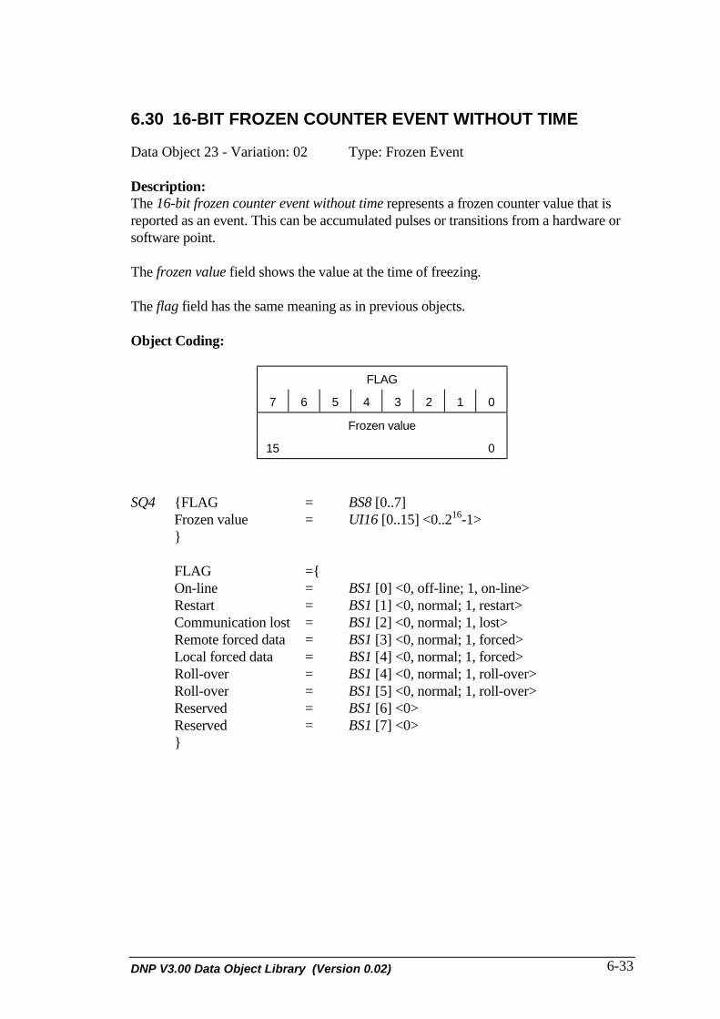
DNP V3.00 Data Object Library (Version 0.02) 6-33
6.30 16-BIT FROZEN COUNTER EVENT WITHOUT TIME
Data Object 23 - Variation: 02 Type: Frozen Event
Description:The 16-bit frozen counter event without time represents a frozen counter value that isreported as an event. This can be accumulated pulses or transitions from a hardware orsoftware point.
The frozen value field shows the value at the time of freezing.
The flag field has the same meaning as in previous objects.
Object Coding:
FLAG
7 6 5 4 3 2 1 0
Frozen value
15 0
SQ4 {FLAG = BS8 [0..7]Frozen value = UI16 [0..15] <0..216-1>}
FLAG ={On-line = BS1 [0] <0, off-line; 1, on-line>Restart = BS1 [1] <0, normal; 1, restart>Communication lost = BS1 [2] <0, normal; 1, lost>Remote forced data = BS1 [3] <0, normal; 1, forced>Local forced data = BS1 [4] <0, normal; 1, forced>Roll-over = BS1 [4] <0, normal; 1, roll-over>Roll-over = BS1 [5] <0, normal; 1, roll-over>Reserved = BS1 [6] <0>Reserved = BS1 [7] <0>}
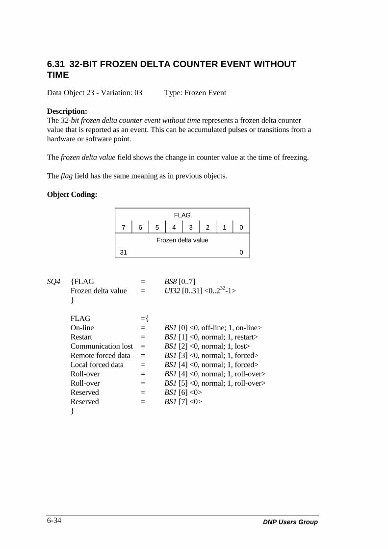
DNP Users Group6-34
6.31 32-BIT FROZEN DELTA COUNTER EVENT WITHOUTTIME
Data Object 23 - Variation: 03 Type: Frozen Event
Description:The 32-bit frozen delta counter event without time represents a frozen delta countervalue that is reported as an event. This can be accumulated pulses or transitions from ahardware or software point.
The frozen delta value field shows the change in counter value at the time of freezing.
The flag field has the same meaning as in previous objects.
Object Coding:
FLAG
7 6 5 4 3 2 1 0
Frozen delta value
31 0
SQ4 {FLAG = BS8 [0..7]Frozen delta value = UI32 [0..31] <0..232-1>}
FLAG ={On-line = BS1 [0] <0, off-line; 1, on-line>Restart = BS1 [1] <0, normal; 1, restart>Communication lost = BS1 [2] <0, normal; 1, lost>Remote forced data = BS1 [3] <0, normal; 1, forced>Local forced data = BS1 [4] <0, normal; 1, forced>Roll-over = BS1 [4] <0, normal; 1, roll-over>Roll-over = BS1 [5] <0, normal; 1, roll-over>Reserved = BS1 [6] <0>Reserved = BS1 [7] <0>}

DNP V3.00 Data Object Library (Version 0.02) 6-35
6.32 16-BIT FROZEN DELTA COUNTER WITHOUT TIME
Data Object 23 - Variation: 04 Type: Frozen Event
Description:The 16-bit frozen delta counter event without time represents a frozen delta countervalue that is reported as an event. This can be accumulated pulses or transitions from ahardware or software point.
The frozen delta value field shows the change in counter value at the time of freezing.
The flag field has the same meaning as in previous objects.
Object Coding:
FLAG
7 6 5 4 3 2 1 0
Frozen delta value
15 0
SQ4 {FLAG = BS8 [0..7]Frozen delta value = UI16 [0..15] <0..216-1>}
FLAG ={On-line = BS1 [0] <0, off-line; 1, on-line>Restart = BS1 [1] <0, normal; 1, restart>Communication lost = BS1 [2] <0, normal; 1, lost>Remote forced data = BS1 [3] <0, normal; 1, forced>Local forced data = BS1 [4] <0, normal; 1, forced>Roll-over = BS1 [4] <0, normal; 1, roll-over>Roll-over = BS1 [5] <0, normal; 1, roll-over>Reserved = BS1 [6] <0>Reserved = BS1 [7] <0>}
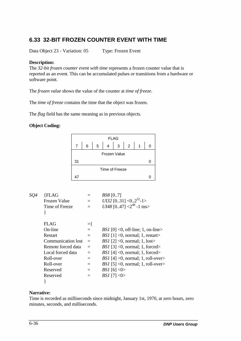
DNP Users Group6-36
6.33 32-BIT FROZEN COUNTER EVENT WITH TIME
Data Object 23 - Variation: 05 Type: Frozen Event
Description:The 32-bit frozen counter event with time represents a frozen counter value that isreported as an event. This can be accumulated pulses or transitions from a hardware orsoftware point.
The frozen value shows the value of the counter at time of freeze.
The time of freeze contains the time that the object was frozen.
The flag field has the same meaning as in previous objects.
Object Coding:
FLAG
7 6 5 4 3 2 1 0
Frozen Value
31 0
Time of Freeze
47 0
SQ4 {FLAG = BS8 [0..7]Frozen Value = UI32 [0..31] <0..232-1>Time of Freeze = UI48 [0..47] <248 -1 ms>}
FLAG ={On-line = BS1 [0] <0, off-line; 1, on-line>Restart = BS1 [1] <0, normal; 1, restart>Communication lost = BS1 [2] <0, normal; 1, lost>Remote forced data = BS1 [3] <0, normal; 1, forced>Local forced data = BS1 [4] <0, normal; 1, forced>Roll-over = BS1 [4] <0, normal; 1, roll-over>Roll-over = BS1 [5] <0, normal; 1, roll-over>Reserved = BS1 [6] <0>Reserved = BS1 [7] <0>}
Narrative:Time is recorded as milliseconds since midnight, January 1st, 1970, at zero hours, zerominutes, seconds, and milliseconds.
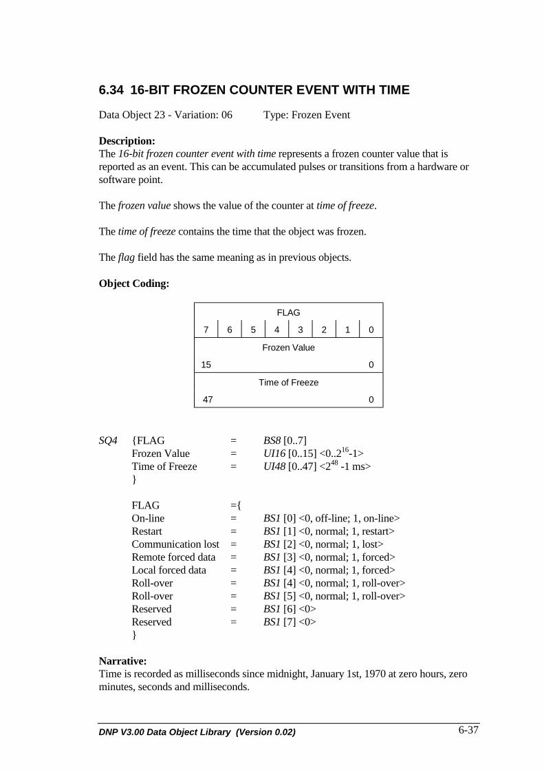
DNP V3.00 Data Object Library (Version 0.02) 6-37
6.34 16-BIT FROZEN COUNTER EVENT WITH TIME
Data Object 23 - Variation: 06 Type: Frozen Event
Description:The 16-bit frozen counter event with time represents a frozen counter value that isreported as an event. This can be accumulated pulses or transitions from a hardware orsoftware point.
The frozen value shows the value of the counter at time of freeze.
The time of freeze contains the time that the object was frozen.
The flag field has the same meaning as in previous objects.
Object Coding:
FLAG
7 6 5 4 3 2 1 0
Frozen Value
15 0
Time of Freeze
47 0
SQ4 {FLAG = BS8 [0..7]Frozen Value = UI16 [0..15] <0..216-1>Time of Freeze = UI48 [0..47] <248 -1 ms>}
FLAG ={On-line = BS1 [0] <0, off-line; 1, on-line>Restart = BS1 [1] <0, normal; 1, restart>Communication lost = BS1 [2] <0, normal; 1, lost>Remote forced data = BS1 [3] <0, normal; 1, forced>Local forced data = BS1 [4] <0, normal; 1, forced>Roll-over = BS1 [4] <0, normal; 1, roll-over>Roll-over = BS1 [5] <0, normal; 1, roll-over>Reserved = BS1 [6] <0>Reserved = BS1 [7] <0>}
Narrative:Time is recorded as milliseconds since midnight, January 1st, 1970 at zero hours, zerominutes, seconds and milliseconds.

DNP Users Group6-38
6.35 32-BIT FROZEN DELTA COUNTER EVENT WITH TIME
Data Object 23 - Variation: 07 Type: Frozen Event
Description:The 32-bit frozen delta counter event with time represents a frozen delta counter valuethat is reported as an event. This can be accumulated pulses or transitions from ahardware or software point.
The frozen value shows the change in the counter at time of freeze.
The time of freeze contains the time that the object was frozen.
The flag field has the same meaning as in previous objects.
Object Coding:
FLAG
7 6 5 4 3 2 1 0
Frozen Value
31 0
Time of Freeze
47 0
SQ4 {FLAG = BS8 [0..7]Frozen Value = UI32 [0..31] <0..232-1>Time of Freeze = UI48 [0..47] <248 -1 ms>}
FLAG ={On-line = BS1 [0] <0, off-line; 1, on-line>Restart = BS1 [1] <0, normal; 1, restart>Communication lost = BS1 [2] <0, normal; 1, lost>Remote forced data = BS1 [3] <0, normal; 1, forced>Local forced data = BS1 [4] <0, normal; 1, forced>Roll-over = BS1 [4] <0, normal; 1, roll-over>Roll-over = BS1 [5] <0, normal; 1, roll-over>Reserved = BS1 [6] <0>Reserved = BS1 [7] <0>}
Narrative:Time is recorded as milliseconds since midnight, January 1st, 1970 at zero hours, zerominutes, seconds and milliseconds.
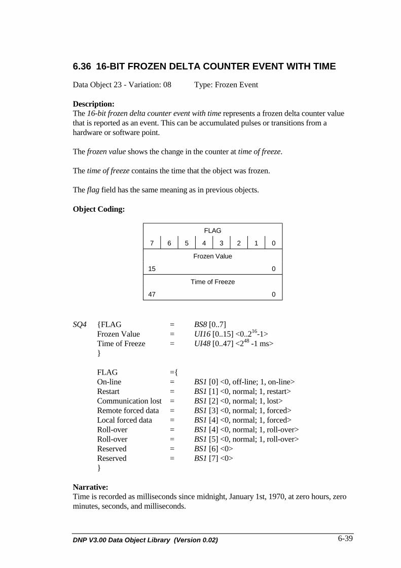
DNP V3.00 Data Object Library (Version 0.02) 6-39
6.36 16-BIT FROZEN DELTA COUNTER EVENT WITH TIME
Data Object 23 - Variation: 08 Type: Frozen Event
Description:The 16-bit frozen delta counter event with time represents a frozen delta counter valuethat is reported as an event. This can be accumulated pulses or transitions from ahardware or software point.
The frozen value shows the change in the counter at time of freeze.
The time of freeze contains the time that the object was frozen.
The flag field has the same meaning as in previous objects.
Object Coding:
FLAG
7 6 5 4 3 2 1 0
Frozen Value
15 0
Time of Freeze
47 0
SQ4 {FLAG = BS8 [0..7]Frozen Value = UI16 [0..15] <0..216-1>Time of Freeze = UI48 [0..47] <248 -1 ms>}
FLAG ={On-line = BS1 [0] <0, off-line; 1, on-line>Restart = BS1 [1] <0, normal; 1, restart>Communication lost = BS1 [2] <0, normal; 1, lost>Remote forced data = BS1 [3] <0, normal; 1, forced>Local forced data = BS1 [4] <0, normal; 1, forced>Roll-over = BS1 [4] <0, normal; 1, roll-over>Roll-over = BS1 [5] <0, normal; 1, roll-over>Reserved = BS1 [6] <0>Reserved = BS1 [7] <0>}
Narrative:Time is recorded as milliseconds since midnight, January 1st, 1970, at zero hours, zerominutes, seconds, and milliseconds.

DNP V3.00 Data Object Library (Version 0.02) 7-1
7. ANALOG INPUT OBJECTDEFINITIONS
This section defines the analog input data objects using the rules established in section 2.DECLARATION RULES FOR INFORMATION ELEMENTS.
7.1 32-BIT ANALOG INPUT
Data Object 30 - Variation: 01 Type: Static
Description:The 32-bit Analog Input is an information object used to represent a hardware orsoftware analog point. The 32-bit signed value could represent a digitized signal orcalculated value.
The Value field shows the current value of the analog input at the time of reporting orthe last reported value from the originating device.
The flag field has the same meaning as previous objects, with these additions:
• The out of range field indicates that the digitized signal or calculation has exceeded+231 -1 positively, or -231 negatively. The actual value will be +231 -1 or -231 if it isover-range or under-range.
• The reference check field indicates that the reference signal used to digitize theanalog input is not stable and the resulting digitized value may not be correct.

DNP Users Group7-2
Object Coding:
FLAG
7 0
Current value
31 0
SQ2 {FLAG = BS8 [0..7]Current value = I32 [0..31] <231-1..-231>}
FLAG ={On-line = BS1 [0] <0, off-line; 1, on-line>Restart = BS1 [1] <0, normal; 1, restart>Communication lost = BS1 [2] <0, normal; 1, lost>Remote forced data = BS1 [3] <0, normal; 1, forced>Local forced data = BS1 [4] <0, normal; 1, forced>Over-range = BS1 [5] <0, normal; 1, over-range>Reference check = BS1 [6] <0, normal; 1, error>Reserved = BS1 [7] <0>}
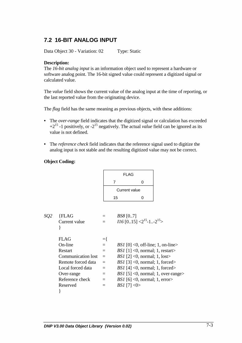
DNP V3.00 Data Object Library (Version 0.02) 7-3
7.2 16-BIT ANALOG INPUT
Data Object 30 - Variation: 02 Type: Static
Description:The 16-bit analog input is an information object used to represent a hardware orsoftware analog point. The 16-bit signed value could represent a digitized signal orcalculated value.
The value field shows the current value of the analog input at the time of reporting, orthe last reported value from the originating device.
The flag field has the same meaning as previous objects, with these additions:
• The over-range field indicates that the digitized signal or calculation has exceeded+215 -1 positively, or -215 negatively. The actual value field can be ignored as itsvalue is not defined.
• The reference check field indicates that the reference signal used to digitize theanalog input is not stable and the resulting digitized value may not be correct.
Object Coding:
FLAG
7 0
Current value
15 0
SQ2 {FLAG = BS8 [0..7]Current value = I16 [0..15] <215-1..-215>}
FLAG ={On-line = BS1 [0] <0, off-line; 1, on-line>Restart = BS1 [1] <0, normal; 1, restart>Communication lost = BS1 [2] <0, normal; 1, lost>Remote forced data = BS1 [3] <0, normal; 1, forced>Local forced data = BS1 [4] <0, normal; 1, forced>Over-range = BS1 [5] <0, normal; 1, over-range>Reference check = BS1 [6] <0, normal; 1, error>Reserved = BS1 [7] <0>}

DNP Users Group7-4
7.3 32-BIT ANALOG INPUT WITHOUT FLAG
Data Object 30 - Variation: 03 Type: Static
Description:The 32-bit analog input is an information object used to represent a hardware orsoftware analog point. The 32-bit signed value could represent a digitized signal orcalculated value.
The value field shows the current value of the analog input at the time of reporting, orthe last reported value from the originating device.
Object Coding:
Current value
31 0
SQ2 {Current value = I32 [0..31] <231-1..-231>}
NOTE: The use of this variation implies that the input point is on-line and thatall other flag bits are normal (i.e. this variation implies that flag = 1).

DNP V3.00 Data Object Library (Version 0.02) 7-5
7.4 16-BIT ANALOG INPUT WITHOUT FLAG
Data Object 30 - Variation: 04 Type: Static
Description:The 16-bit analog input is an information object used to represent a hardware orsoftware analog point. The 16-bit signed value could represent a digitized signal orcalculated value.
The current value field shows the current value of the analog input at the time ofreporting, or the last reported value from the originating device.
Object Coding:
Current value
15 0
SQ2 {Current value = I16 [0..15] <215-1..-215>}
NOTE: The use of this variation implies that the input point is on-line and thatall other flag bits are normal (i.e. this variation implies that flag = 1).

DNP Users Group7-6
7.5 32-BIT FROZEN ANALOG INPUT
Data Object 31 - Variation: 01 Type: Frozen Static
Description:The 32-bit frozen analog input is an information object used to represent a frozenhardware or software analog point. The 32-bit signed value could represent a digitizedsignal or calculated value.
The frozen value shows the value of the analog input at the time the last freezecommand was performed on this point.
The flag field has the same meaning as previous objects, with these additions:
• The over-range field indicates that the digitized signal or calculation has exceeded+231 -1 positively, or -231 negatively. The actual value field can be ignored as itsvalue is not defined.
• The reference check field indicates that the reference signal used to digitize theanalog input is not stable, and the resulting digitized value may not be correct.
Object Coding:
FLAG
7 0
Frozen value
31 0
SQ2 {FLAG = BS8 [0..7]Current value = I32 [0..31] <231-1..-231>}
FLAG ={On-line = BS1 [0] <0, off-line; 1, on-line>Restart = BS1 [1] <0, normal; 1, restart>Communication lost = BS1 [2] <0, normal; 1, lost>Remote forced data = BS1 [3] <0, normal; 1, forced>Local forced data = BS1 [4] <0, normal; 1, forced>Over-range = BS1 [5] <0, normal; 1, over-range>Reference check = BS1 [6] <0, normal; 1, error>Reserved = BS1 [7] <0>}

DNP V3.00 Data Object Library (Version 0.02) 7-7
7.6 16-BIT FROZEN ANALOG INPUT
Data Object 31 - Variation: 02 Type: Frozen Static
Description:The 16-bit frozen analog input is an information object used to represent a frozenhardware or software analog point. The 16-bit signed value could represent a digitizedsignal or calculated value.
The frozen value shows the value of the analog input at the time the last freezecommand was performed on this point.
The flag field has the same meaning as previous objects, with these additions:
• The over-range field indicates that the digitized signal or calculation has exceeded+215 -1 positively, or -215 negatively. The actual value field can be ignored as itsvalue is not defined.
• The reference check field indicates that the reference signal used to digitize theanalog input is not stable, and the resulting digitized value may not be correct.
Object Coding:
FLAG
7 0
Frozen value
15 0
SQ2 {FLAG = BS8 [0..7]Current value = I16 [0..15] <215-1..-215>}
FLAG ={On-line = BS1 [0] <0, off-line; 1, on-line>Restart = BS1 [1] <0, normal; 1, restart>Communication lost = BS1 [2] <0, normal; 1, lost>Remote forced data = BS1 [3] <0, normal; 1, forced>Local forced data = BS1 [4] <0, normal; 1, forced>Over-range = BS1 [5] <0, normal; 1, over-range>Reference check = BS1 [6] <0, normal; 1, error>Reserved = BS1 [7] <0>}
DNP Users Group7-8
7.7 32-BIT FROZEN ANALOG INPUT WITH TIME OF FREEZE
Data Object 31 - Variation: 03 Type: Frozen Static
Description:The 32-bit frozen analog input with time of freeze is an information object used torepresent a frozen hardware or software analog point. The 32-bit signed value couldrepresent a digitized signal or calculated value.
The frozen value shows the value of the analog input at the time specified in time offreeze.
The time of freeze field shows the time at which the frozen value was equal to thecurrent value of the analog input. These values are equated on reception of a freezeanalog command.
The flag field has the same meaning as previous objects, with these additions:
• The over-range field indicates that the digitized signal or calculation has exceeded+231 -1 positively, or -231 negatively. The actual value field can be ignored as itsvalue is not defined.
• The reference check field indicates that the reference signal used to digitize theanalog input is not stable and the resulting digitized value may not be correct.

DNP V3.00 Data Object Library (Version 0.02) 7-9
Object Coding:
FLAG
7 0
Frozen value
31 0
Time of Freeze
47 0
SQ2 {FLAG = BS8 [0..7]Current value = I32 [0..31] <231-1..-231>Time of Freeze = UI48[0..47] <0 .. 2 48 >}
FLAG ={On-line = BS1 [0] <0, off-line; 1, on-line>Restart = BS1 [1] <0, normal; 1, restart>Communication lost = BS1 [2] <0, normal; 1, lost>Remote forced data = BS1 [3] <0, normal; 1, forced>Local forced data = BS1 [4] <0, normal; 1, forced>Over-range = BS1 [5] <0, normal; 1, over-range>Reference check = BS1 [6] <0, normal; 1, error>Reserved = BS1 [7] <0>}

DNP Users Group7-10
7.8 16-BIT FROZEN ANALOG INPUT WITH TIME OF FREEZE
Data Object 31 - Variation: 04 Type: Frozen Static
Description:The 16-bit frozen analog input with time of freeze is an information object used torepresent a frozen hardware or software analog point. The 16-bit signed value couldrepresent a digitized signal or calculated value.
The frozen value shows the value of the analog input at the time specified in time offreeze.
The time of freeze field shows the time at which the frozen value was equal to thecurrent value of the analog input. These values are equated on reception of a freezeanalog command.
The flag field has the same meaning as previous objects, with these additions:
• The over-range field indicates that the digitized signal or calculation has exceeded+215 -1 positively, or -215 negatively. The actual value field can be ignored as itsvalue is not defined.
• The reference check field indicates that the reference signal used to digitize theanalog input is not stable, and the resulting digitized value may not be correct.

DNP V3.00 Data Object Library (Version 0.02) 7-11
Object Coding:
FLAG
7 0
Frozen value
15 0
Time of Freeze
47 0
SQ2 {FLAG = BS8 [0..7]Time of freeze = UI48[0..47] <0 .. 2 48 -1>Current value = I16 [0..15] <215-1..-215>}
FLAG ={On-line = BS1 [0] <0, off-line; 1, on-line>Restart = BS1 [1] <0, normal; 1, restart>Communication lost = BS1 [2] <0, normal; 1, lost>Remote forced data = BS1 [3] <0, normal; 1, forced>Local forced data = BS1 [4] <0, normal; 1, forced>Over-range = BS1 [5] <0, normal; 1, over-range>Reference check = BS1 [6] <0, normal; 1, error>Reserved = BS1 [7] <0>}

DNP Users Group7-12
7.9 32-BIT FROZEN ANALOG INPUT WITHOUT FLAG
Data Object 31 - Variation: 05 Type: Frozen Static
Description:The 32-bit frozen analog input is an information object used to represent a frozenhardware or software analog point. The 32-bit signed value could represent a digitizedsignal or calculated value.
The frozen value shows the value of the analog input at the time the last freezecommand was performed on this point.
Object Coding:
Frozen value
31 0
SQ2 {Current value= I32 [0..31] <231-1..-231>}
NOTE: The use of this variation implies that the input point is on-line and thatall other flag bits are normal (i.e. this variation implies that flag = 1).

DNP V3.00 Data Object Library (Version 0.02) 7-13
7.10 16-BIT FROZEN ANALOG INPUT WITHOUT FLAG
Data Object 31 - Variation: 06 Type: Frozen Static
Description:The 16-bit frozen analog input is an information object used to represent a frozenhardware or software analog point. The 16-bit signed value could represent a digitizedsignal or calculated value.
The frozen value shows the value of the analog input at the time the last freezecommand was performed on this point.
Object Coding:
Frozen value
15 0
SQ2 {Current value= I16 [0..15] <215-1..-215>}

DNP Users Group7-14
7.11 32-BIT ANALOG CHANGE EVENT WITHOUT TIME
Data Object 32 - Variation: 01 Type: Event
Description:The 32-bit analog change event without time is an information object used torepresent a changed hardware or software analog point. The 32-bit signed value couldrepresent a digitized signal or calculated value.
The current value field shows the current value of the analog input at the time ofreporting, or the last reported value from the originating device. This object will onlybe reported if the current value and the last reported value differ by a configurabledeadband value. This filtering is commonly known as deadbanding.
The flag field has the same meaning as previous objects, with these additions:
• The over-range field indicates that the digitized signal or calculation has exceeded+231 -1 positively, or -231 negatively. The actual value field can be ignored as itsvalue is not defined.
• The reference check field indicates that the reference signal used to digitize theanalog input is not stable, and the resulting digitized value may not be correct.
Object Coding:
FLAG
7 0
Current value
31 0
SQ2 {FLAG = BS8 [0..7]Current value = I32 [0..31] <231-1..-231>}
FLAG ={On-line = BS1 [0] <0, off-line; 1, on-line>Restart = BS1 [1] <0, normal; 1, restart>Communication lost = BS1 [2] <0, normal; 1, lost>Remote forced data = BS1 [3] <0, normal; 1, forced>Local forced data = BS1 [4] <0, normal; 1, forced>Over-range = BS1 [5] <0, normal; 1, over-range>Reference check = BS1 [6] <0, normal; 1, error>Reserved = BS1 [7] <0>}

DNP V3.00 Data Object Library (Version 0.02) 7-15
7.12 16-BIT CHANGE EVENT WITHOUT TIME
Data Object 32 - Variation: 02 Type: Event
Description:The 16-bit analog change event without time is an information object used torepresent a changed hardware or software analog point. The 16-bit signed value couldrepresent a digitized signal or calculated value.
The current value field shows the current value of the analog input at the time ofreporting, or the last reported value from the originating device. This object will onlybe reported if the current value and the last reported value differ by a configurabledeadband value. This filtering is commonly known as deadbanding.
The flag field has the same meaning as previous objects, with these additions:
• The over-range field indicates that the digitized signal or calculation has exceeded+215 -1 positively, or -215 negatively. The actual value field can be ignored as itsvalue is not defined.
• The reference check field indicates that the reference signal used to digitize theanalog input is not stable, and the resulting digitized value may not be correct.
Object Coding:
FLAG
7 0
Current value
15 0
SQ2 {FLAG = BS8 [0..7]Current value = I16 [0..15] <215-1..-215>}
FLAG ={On-line = BS1 [0] <0, off-line; 1, on-line>Restart = BS1 [1] <0, normal; 1, restart>Communication lost = BS1 [2] <0, normal; 1, lost>Remote forced data = BS1 [3] <0, normal; 1, forced>Local forced data = BS1 [4] <0, normal; 1, forced>Over-range = BS1 [5] <0, normal; 1, over-range>Reference check = BS1 [6] <0, normal; 1, error>Reserved = BS1 [7] <0>}

DNP Users Group7-16
7.13 32-BIT ANALOG CHANGE EVENT WITH TIME
Data Object 32 - Variation: 03 Type: Event
Description:The 32-bit analog change event with time is an information object used to represent achanged hardware or software analog point. The 32-bit signed value could represent adigitized signal or calculated value.
The current value shows the value of the analog input at the time specified in time.
The time field shows the time at which the processing caused the event.
The flag field has the same meaning as previous objects, with these additions:
• The over-range field indicates that the digitized signal or calculation has exceeded+231 -1 positively, or -231 negatively. The actual value field can be ignored as itsvalue is not defined.
• The reference check field indicates that the reference signal used to digitize theanalog input is not stable, and the resulting digitized value may not be correct.
Object Coding:
FLAG
7 0
Value
31 0
Time
47 0
SQ2 {FLAG = BS8 [0..7]Time = UI48[0..47] <0 .. 2 48 -1>Value = I32[0..31] <231-1..-231>}
FLAG ={On-line = BS1 [0] <0, off-line; 1, on-line>Restart = BS1 [1] <0, normal; 1, restart>Communication lost = BS1 [2] <0, normal; 1, lost>Remote forced data = BS1 [3] <0, normal; 1, forced>Local forced data = BS1 [4] <0, normal; 1, forced>Over-range = BS1 [5] <0, normal; 1, over-range>Reference check = BS1 [6] <0, normal; 1, error>Reserved = BS1 [7] <0>}

DNP V3.00 Data Object Library (Version 0.02) 7-17
7.14 16-BIT ANALOG CHANGE EVENT WITH TIME
Data Object 32 - Variation: 04 Type: Event
Description:The 16-bit analog change event with time is an information object used to represent achanged hardware or software analog point. The 16-bit signed value could represent adigitized signal or calculated value.
The current value shows the value of the analog input at the time specified in time.
The time field shows the time at which the processing caused the event.
The flag field has the same meaning as previous objects, with these additions:
• The over-range field indicates that the digitized signal or calculation has exceeded+215 -1 positively, or -215 negatively. The actual value field can be ignored as itsvalue is not defined.
• The reference check field indicates that the reference signal used to digitize theanalog input is not stable, and the resulting digitized value may not be correct.
Object Coding:
FLAG
7 0
Value
15 0
Time
47 0
SQ2 {FLAG = BS8 [0..7]Time = UI48 [0..47] <0 .. 2 48 -1>Value = I16 [0..15] <215-1..-215>}
FLAG ={On-line = BS1 [0] <0, off-line; 1, on-line>Restart = BS1 [1] <0, normal; 1, restart>Communication lost = BS1 [2] <0, normal; 1, lost>Remote forced data = BS1 [3] <0, normal; 1, forced>Local forced data = BS1 [4] <0, normal; 1, forced>Over-range = BS1 [5] <0, normal; 1, over-range>Reference check = BS1 [6] <0, normal; 1, error>Reserved = BS1 [7] <0>}

DNP Users Group7-18
7.15 32-BIT FROZEN ANALOG EVENT WITHOUT TIME
Data Object 33 - Variation: 01 Type: Frozen Event
Description:The 32-bit frozen analog event without time is an information object used to representa frozen hardware or software analog point that is reported as an event. The 32-bitsigned value could represent a digitized signal or calculated value.
The frozen value field shows the value of the analog input at the time of freeze.
The flag field has the same meaning as previous objects, with these additions:
• The over-range field indicates that the digitized signal or calculation has exceeded+231 -1 positively, or -231 negatively. The actual value field can be ignored as itsvalue is not defined.
• The reference check field indicates that the reference signal used to digitize theanalog input is not stable, and the resulting digitized value may not be correct.
Object Coding:
FLAG
7 0
Frozen value
31 0
SQ2 {FLAG = BS8 [0..7]Frozen value = I32 [0..31] <231-1..-231>}
FLAG ={On-line = BS1 [0] <0, off-line; 1, on-line>Restart = BS1 [1] <0, normal; 1, restart>Communication lost = BS1 [2] <0, normal; 1, lost>Remote forced data = BS1 [3] <0, normal; 1, forced>Local forced data = BS1 [4] <0, normal; 1, forced>Over-range = BS1 [5] <0, normal; 1, over-range>Reference check = BS1 [6] <0, normal; 1, error>Reserved = BS1 [7] <0>}

DNP V3.00 Data Object Library (Version 0.02) 7-19
7.16 16-BIT FROZEN ANALOG EVENT WITHOUT TIME
Data Object 33 - Variation: 02 Type: Frozen Event
Description:The 16-bit frozen analog event without time is an information object used to representa frozen hardware or software analog point that is reported as an event. The 16-bitsigned value could represent a digitized signal or calculated value.
The frozen value field shows the value of the analog input at the time of freeze.
The flag field has the same meaning as previous objects, with these additions:
• The over-range field indicates that the digitized signal or calculation has exceeded+215 -1 positively, or -215 negatively. The actual value field can be ignored as itsvalue is not defined.
• The reference check field indicates that the reference signal used to digitize theanalog input is not stable, and the resulting digitized value may not be correct.
Object Coding:
FLAG
7 0
Frozen value
15 0
SQ2 {FLAG = BS8 [0..7]Frozen value = I16 [0..15] <215-1..-215>}
FLAG ={On-line = BS1 [0] <0, off-line; 1, on-line>Restart = BS1 [1] <0, normal; 1, restart>Communication lost = BS1 [2] <0, normal; 1, lost>Remote forced data = BS1 [3] <0, normal; 1, forced>Local forced data = BS1 [4] <0, normal; 1, forced>Over-range = BS1 [5] <0, normal; 1, over-range>Reference check = BS1 [6] <0, normal; 1, error>Reserved = BS1 [7] <0>}
DNP Users Group7-20
7.17 32-BIT FROZEN ANALOG EVENT WITH TIME
Data Object 33 - Variation: 03 Type: Frozen Event
Description:The 32-bit frozen analog event with time is an information object used to represent afrozen hardware or software analog point that is reported as an event. The 32-bitsigned value could represent a digitized signal or calculated value.
The frozen value field shows the value of the analog input at the time of a freeze.
The flag field has the same meaning as previous objects, with these additions:
• The over-range field indicates that the digitized signal or calculation has exceeded+231 -1 positively, or -231 negatively. The actual value field can be ignored as itsvalue is not defined.
• The reference check field indicates that the reference signal used to digitize theanalog input is not stable, and the resulting digitized value may not be correct.
• The time of freeze field shows the time at which the frozen value was equal to thecurrent value of the analog input. These values are equated on reception of a freezeanalog command.

DNP V3.00 Data Object Library (Version 0.02) 7-21
Object Coding:
FLAG
7 0
Frozen value
31 0
Time of Freeze
47 0
SQ2 {FLAG = BS8 [0..7]Frozen value = I32 [0..31] <231-1..-231>Time of Freeze = UI48[0..47] <0 .. 2 48 -1>}
FLAG ={On-line = BS1 [0] <0, off-line; 1, on-line>Restart = BS1 [1] <0, normal; 1, restart>Communication lost = BS1 [2] <0, normal; 1, lost>Remote forced data = BS1 [3] <0, normal; 1, forced>Local forced data = BS1 [4] <0, normal; 1, forced>Over-range = BS1 [5] <0, normal; 1, over-range>Reference check = BS1 [6] <0, normal; 1, error>Reserved = BS1 [7] <0>}

DNP Users Group7-22
7.18 16-BIT FROZEN ANALOG EVENT WITH TIME
Data Object 33 - Variation: 04 Type: Frozen Event
Description:The 16-bit frozen analog event with time is an information object used to represent afrozen hardware or software analog point that is reported as an event. The 16-bitsigned value could represent a digitized signal or calculated value.
The frozen value field shows the value of the analog input at the time of a freeze.
The Flag field has the same meaning as previous objects with these additions:
• The over-range field indicates that the digitized signal or calculation has exceeded+215 -1 positively, or -215 negatively. The actual value field can be ignored as itsvalue is not defined.
• The reference check field indicates that the reference signal used to digitize theanalog input is not stable, and the resulting digitized value may not be correct.
• The time of freeze field shows the time at which the frozen value was equal to thecurrent value of the analog input. These values are equated on reception of a freezeanalog command.
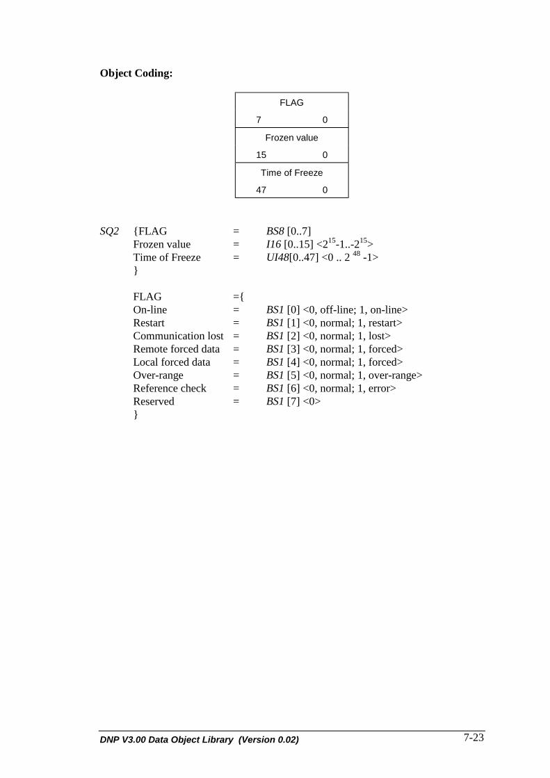
DNP V3.00 Data Object Library (Version 0.02) 7-23
Object Coding:
FLAG
7 0
Frozen value
15 0
Time of Freeze
47 0
SQ2 {FLAG = BS8 [0..7]Frozen value = I16 [0..15] <215-1..-215>Time of Freeze = UI48[0..47] <0 .. 2 48 -1>}
FLAG ={On-line = BS1 [0] <0, off-line; 1, on-line>Restart = BS1 [1] <0, normal; 1, restart>Communication lost = BS1 [2] <0, normal; 1, lost>Remote forced data = BS1 [3] <0, normal; 1, forced>Local forced data = BS1 [4] <0, normal; 1, forced>Over-range = BS1 [5] <0, normal; 1, over-range>Reference check = BS1 [6] <0, normal; 1, error>Reserved = BS1 [7] <0>}

DNP V3.00 Data Object Library (Version 0.02) 8-1
8. ANALOG OUTPUT OBJECTDEFINITIONS
This section defines the analog output data objects using the rules established insection 2. DECLARATION RULES FOR INFORMATION ELEMENTS.
8.1 32-BIT ANALOG OUTPUT STATUS
Data Object 40 - Variation: 01 Type: Static
Description:The 32-bit analog output status information object represents the actual value of ananalog output or software point and associated status.
The actual value field contains the current value of the analog output.
The flag field has the same meaning as previous objects.
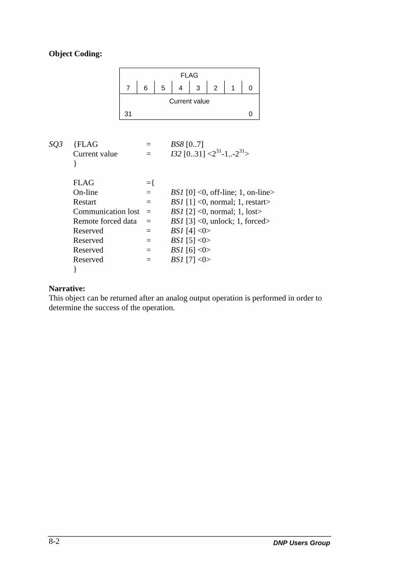
DNP Users Group8-2
Object Coding:
FLAG
7 6 5 4 3 2 1 0
Current value
31 0
SQ3 {FLAG = BS8 [0..7]Current value = I32 [0..31] <231-1..-231>}
FLAG ={On-line = BS1 [0] <0, off-line; 1, on-line>Restart = BS1 [1] <0, normal; 1, restart>Communication lost = BS1 [2] <0, normal; 1, lost>Remote forced data = BS1 [3] <0, unlock; 1, forced>Reserved = BS1 [4] <0>Reserved = BS1 [5] <0>Reserved = BS1 [6] <0>Reserved = BS1 [7] <0>}
Narrative:This object can be returned after an analog output operation is performed in order todetermine the success of the operation.

DNP V3.00 Data Object Library (Version 0.02) 8-3
8.2 16-BIT ANALOG OUTPUT STATUS
Data Object 40 - Variation: 02 Type: Static
Description:The 16-bit analog output status information object represents the actual value of ahardware DAC analog output or software point and associated status.
The actual value field contains the current value of the analog output.
The flag field has the same meaning as previous objects.
Object Coding:
FLAG
7 6 5 4 3 2 1 0
Current value
15 0
SQ3 {FLAG = BS8 [0..7]Current value = I16 [0..15] <215-1..-215>}
FLAG ={On-line = BS1 [0] <0, off-line; 1, on-line>Restart = BS1 [1] <0, normal; 1, restart>Communication lost = BS1 [2] <0, normal; 1, lost>Remote forced data = BS1 [3] <0, unlock; 1, forced>Reserved = BS1 [4] <0>Reserved = BS1 [5] <0>Reserved = BS1 [6] <0>Reserved = BS1 [7] <0>}
Narrative:This object can be returned after an analog output operation is performed in order todetermine the success of the operation.

DNP Users Group8-4
8.3 32-BIT ANALOG OUTPUT BLOCK
Data Object 41 - Variation: 01 Type: Static
Description:The 32-bit analog output information object represents the desired value of ahardware DAC analog output or software point. The value represented is merelylogical, as the value may be scaled and/or manipulated before any output level is set.
The requested value field contains the desired value of the analog output. The actualvalue of the analog output is returned in the analog output status object.
The control status field indicates the status of the analog control operation, in thesame way that the control delay output block does. The definition of this field is thesame as the control relay output block.
Object Coding:
Requested value
31 0
Control Status
7 0
Requested value = I32 [0..31] <231-1..-231>Status = I8 [0..7] <0..255>
This is used in a control request/response.

DNP V3.00 Data Object Library (Version 0.02) 8-5
8.4 16-BIT ANALOG OUTPUT BLOCK
Data Object 41 - Variation: 02 Type: Static
Description:The 16-bit analog output block information object represents the desired value of ahardware DAC analog output or software point. The value represented is merelylogical, as the value may be scaled and/or manipulated before any output level is set.
The requested value field contains the desired value of the analog output. The actualvalue of the analog output is returned in the analog output status object.
The control status field indicates the status of the analog control operation in the sameway as the control relay output block. The definition of this field is the same as thecontrol relay output block.
Object Coding:
Requested value
15 0
Control Status
7 0
I16 Requested value = I16 [0..15] <215-1..-215>I8 Status = I8 [0..7] <0..255>

DNP Users Group8-6

DNP V3.00 Data Object Library (Version 0.02) 9-1
9. TIME OBJECT DEFINITIONS
This section defines the time data objects using the rules established in section 2.DECLARATION RULES FOR INFORMATION ELEMENTS.
9.1 TIME AND DATE
Data Object 50 - Variation: 01
Description:The time and date object is an information object that represents the absolute time ofday and date. This object should be used for time-synchronization.
Object Coding:
Absolute Time
7 6 5 4 3 2 1 0
15 14 13 12 11 10 9 8
23 22 21 20 19 18 17 16
31 30 29 28 27 26 25 24
39 38 37 36 35 34 33 32
47 46 45 44 43 42 41 40
Absolute Time= UI48 [0..47] <0..248-1, msec>
Narrative:Absolute Time is recorded as milliseconds since midnight, January 1st, 1970, at zerohours, zero minutes, zero seconds, and milliseconds.
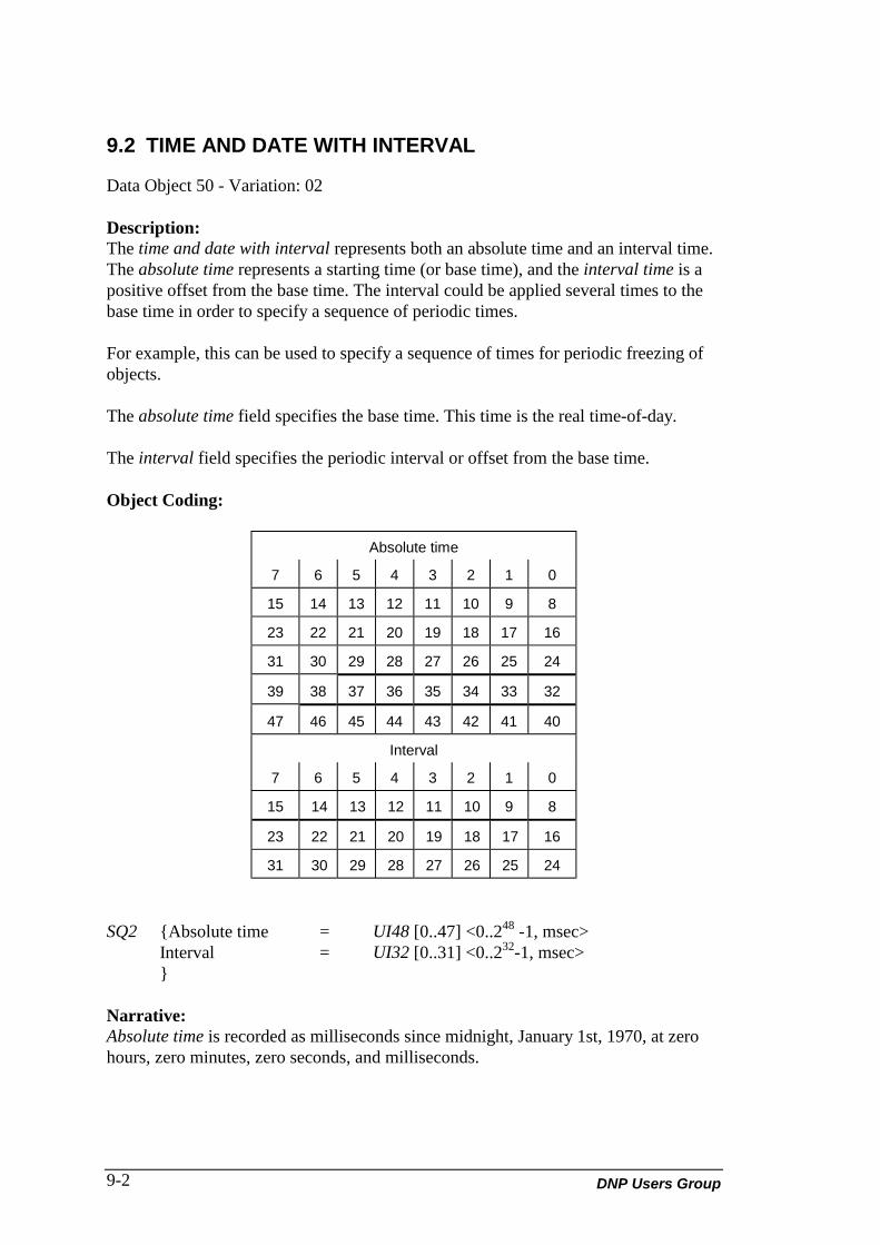
DNP Users Group9-2
9.2 TIME AND DATE WITH INTERVAL
Data Object 50 - Variation: 02
Description:The time and date with interval represents both an absolute time and an interval time.The absolute time represents a starting time (or base time), and the interval time is apositive offset from the base time. The interval could be applied several times to thebase time in order to specify a sequence of periodic times.
For example, this can be used to specify a sequence of times for periodic freezing ofobjects.
The absolute time field specifies the base time. This time is the real time-of-day.
The interval field specifies the periodic interval or offset from the base time.
Object Coding:
Absolute time
7 6 5 4 3 2 1 0
15 14 13 12 11 10 9 8
23 22 21 20 19 18 17 16
31 30 29 28 27 26 25 24
39 38 37 36 35 34 33 32
47 46 45 44 43 42 41 40
Interval
7 6 5 4 3 2 1 0
15 14 13 12 11 10 9 8
23 22 21 20 19 18 17 16
31 30 29 28 27 26 25 24
SQ2 {Absolute time = UI48 [0..47] <0..248 -1, msec>Interval = UI32 [0..31] <0..232-1, msec>}
Narrative:Absolute time is recorded as milliseconds since midnight, January 1st, 1970, at zerohours, zero minutes, zero seconds, and milliseconds.

DNP V3.00 Data Object Library (Version 0.02) 9-3
9.3 TIME AND DATE CTO
Data Object 51 - Variation: 01
Description:The time and date CTO (common time of occurrence) object is an information objectthat represents the absolute time of day. This object should be used in conjunctionwith other objects that contain time references. This object is a base time to which arelative (incremental) time can be added, or from which it can be subtracted, in orderto obtain another absolute time reference.
Object Coding:
Absolute Time
7 6 5 4 3 2 1 0
15 14 13 12 11 10 9 8
23 22 21 20 19 18 17 16
31 30 29 28 27 26 25 24
39 38 37 36 35 34 33 32
47 46 45 44 43 42 41 40
Absolute time = UI48 [0..47] <0..248-1, msec>
Narrative:Absolute time is recorded as milliseconds since midnight, January 1st, 1970, at zerohours, zero minutes, zero seconds, and milliseconds.

DNP Users Group9-4
9.4 UN-SYNCHRONIZED TIME AND DATE CTO
Data Object 51 - Variation: 02
Description:The un-synchronized time and date CTO object is an information object thatrepresents the relative-absolute time of day. This object should be used in conjunctionwith other objects that contain time references. This object is a relative base time towhich a relative (incremental) time can be added, or from which it can be subtracted,in order to obtain another relative-absolute time reference. The real absolute time canbe calculated by the message receiver, based on the reception time of the messagecontaining this object. Any objects that follow this object, and come before the nextcommon-time object that contains relative time, must be corrected using this relative-absolute time value.
Relative-absolute time is the un-synchronized time-of-day at the station sending thisobject (i.e. the responding station).
Object Coding:
Relative Absolute Time
7 6 5 4 3 2 1 0
15 14 13 12 11 10 9 8
23 22 21 20 19 18 17 16
31 30 29 28 27 26 25 24
39 38 37 36 35 34 33 32
47 46 45 44 43 42 41 40
Relative-absolute time = UI48 [0..47] <0..248-1, msec>
Narrative:Relative-absolute time is recorded as milliseconds since midnight, January 1st, 1970,at zero hours, zero minutes, zero seconds, and milliseconds.
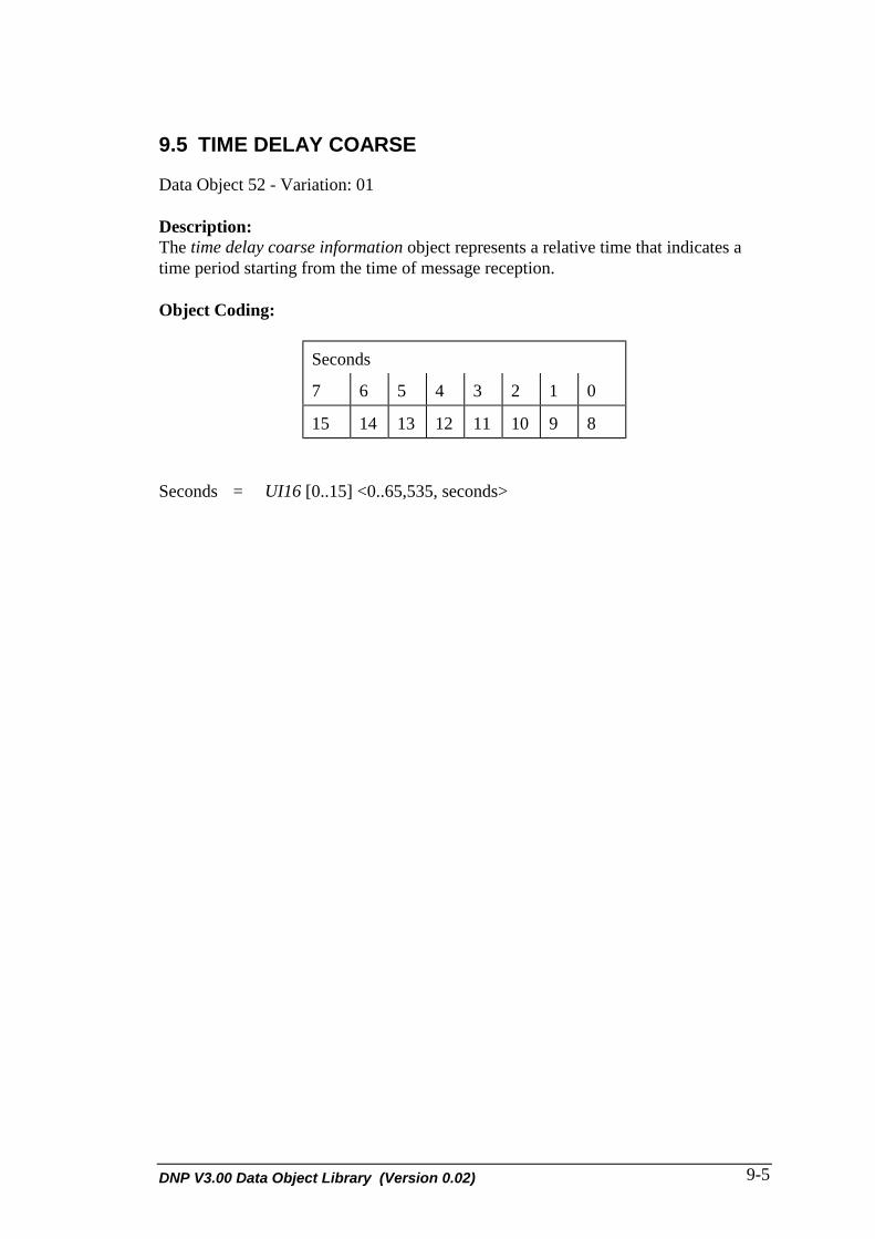
DNP V3.00 Data Object Library (Version 0.02) 9-5
9.5 TIME DELAY COARSE
Data Object 52 - Variation: 01
Description:The time delay coarse information object represents a relative time that indicates atime period starting from the time of message reception.
Object Coding:
Seconds
7 6 5 4 3 2 1 0
15 14 13 12 11 10 9 8
Seconds = UI16 [0..15] <0..65,535, seconds>

DNP Users Group9-6
9.6 TIME DELAY FINE
Data Object 52 - Variation: 02
Description:The time delay fine information object represents a relative time that indicates a timeperiod starting from the time of message reception. This object can be used in time-synchronization to perform path delay measurement calculations or other functionsthat require time-based calibration.
Object Coding:
Milliseconds
7 6 5 4 3 2 1 0
15 14 13 12 11 10 9 8
Milliseconds = UI16 [0..15] <0..65,535, milliseconds>

DNP V3.00 Data Object Library (Version 0.02) 9-7


DNP V3.00 Data Object Library (Version 0.02) 10-1
10. CLASS OBJECT DEFINITIONS
This section defines the class data objects using the rules established in section 2.DECLARATION RULES FOR INFORMATION ELEMENTS.
10.1 CLASS 0 DATA
Data Object 60 - Variation: 01
Description:The class 0 data object is an object place-holder that specifies a class of zero or moreinformation elements. These elements can be entire object types, a specific variation,certain points of the variation, or any combination of these. The data specified by thisobject type is configurable within the responding station.
Class 0 data is potentially any information object not assigned to class 1, 2, or 3. Thatis, class 0 data is non-priority data.
Object Coding:None.
Narrative:The class 0 data object does not carry any information in itself, and therefore does nothave an object coding. Class 0 is a null class to which all data objects not assigned toother classes can belong by default.

DNP Users Group10-2
10.2 CLASS 1 DATA
Data Object 60 - Variation: 02
Description:The class 1 data object is an object place-holder that specifies a class of zero or moreinformation elements. These elements can be entire object types, a specific variation,certain points of the variation, or any combination of these. The data specified by thisobject type is configurable within the responding station.
The responding station does not send the class 1 data object, as it does not containany actual information, but is simply an identifier for other objects.
Object Coding:None.
Narrative:The class 1 data object is used to request a configured group, usually changes, ofinformation objects from a responding station. This data object does not carry anyinformation in itself, and therefore does not have an object coding.
Typically, class 1 data has higher priority than class 2, class 3, and class 0 data.

DNP V3.00 Data Object Library (Version 0.02) 10-3
10.3 CLASS 2 DATA
Data Object 60 - Variation: 03
Description:The class 2 data object is an object place-holder that specifies a class of zero or moreinformation elements. These elements can be entire object types, a specific variation,certain points of the variation, or any combination of these. The data specified by thisobject type is configurable within the responding station.
The responding station does not send the class 2 data object, as it does not containany actual information, but is simply an identifier for other objects.
Object Coding:None.
Narrative:The class 2 data object is used to request a configured group, usually changes, ofinformation objects from a responding station. This data object does not carry anyinformation in itself, and therefore does not have an object coding.

DNP Users Group10-4
10.4 CLASS 3 DATA
Data Object 60 - Variation: 04
Description:The class 3 data object is an object place-holder that specifies a class of zero or moreinformation elements. These elements can be entire object types, a specific variation,certain points of the variation, or any combination of these. The data specified by thisobject type is configurable within the responding station.
The responding station does not send the class 3 data object, as it does not containany actual information, but is simply an identifier for other objects.
Object Coding:None.
Narrative:The class 3 data object is used to request a configured group, usually an event, ofinformation objects from a responding station. The data object does not carry anyinformation in itself, and therefore does not have an object coding.

DNP V3.00 Data Object Library (Version 0.02) 11-1
11. FILE OBJECT DEFINITIONS
This section defines the file data objects using the rules established in section 2.DECLARATION RULES FOR INFORMATION ELEMENTS.
11.1 FILE IDENTIFIER
Data Object 70 - Variation: 01
Description:The file identifier object is an information object that represents information about afile in a network file system. This object is intended to be used for transferring largeblocks of data that do not follow the format of an existing data object. In particular,this object is suitable for uploading and downloading configuration files to remotedevices or data concentrators.
File operations are defined for this object to allow copying, deleting, etc. of a file. Thecontents of the file object and the exact procedure to perform on the file will not beinterpreted by the Application Layer, and so must be performed by the user of theApplication Layer.
Networking Capability:The File_Name field defines a logical name of a file or device. The receivingapplication should interpret this name as a network file name. The root (or /)represents the root of the host file system or receiving node. Sub-directories off of theroot are interpreted as branches off of the root. A branch can be a new directory, ormore importantly, the directory can be a remote file system which resides in a remotedevice that is accessible from the current node.
When an application receives a file that specifies a directory or file that does notreside in the current file system, the application must do whatever is necessary toobtain the file from the specified device.
If the remote device is a DNP 3 device, then the following rules apply:
• On reception of a non-local file request, the application shall forward the request(in its entirety) to the appropriate DNP 3 device.
• The File_Name field will be modified so that the root of the remote device isspecified by the File_Name field. This means stripping off any paths that were usedto actually derive the name of the remote device.

DNP Users Group11-2
For example, an IED configuration is sent from a host through two data concentratorsDC1 and DC2. The name from the Host to DC1 is:
\DC2\IED\config1
The name from the DC1 to DC2 is:
\IED\config1
The name from the DC2 to IED is:
\config1
In this case DC2 and IED were logical directories which specified remote devices andconfig1 was the name of a physical file.
Object Coding:This is not a fixed format object, but it is a variable format/sized object. This part ofthe object is sent in a request.
31 24 23 16 15 8 7 0
Attributes File_Type Name_Size
End_Record Start_Record
File_Size
Time_Of_Creation
Permission
File_ID
Owner_ID
Group_ID
Status File_Function
X File_Name 0
The File_Name field consists of 0 .. x bits where x = Name_Size * 8 and Name_Size =0 .. 65535.
The file identifier object is sent in a DNP application request message to a remotedevice using the Application Layer WRITE request function code. A device respondsto a request (or spontaneously reports) the file identifier object with an ApplicationLayer RESPONSE or UNSOLICITED RESPONSE function code (where appropriate).
File_Name: Name of file to perform operation on. Consists of 1 or more ofthe characters A .. Z, a..z, 0 .. 9, ".", "_", "\" and "-" ONLY,where " is a delimiter, and where the hyphen cannot be used asthe first character of the file name. The size of this field isdetermined by the Name_Size field below. The name can

DNP V3.00 Data Object Library (Version 0.02) 11-3
contain all path information starting from the root (i.e. "\" of thefile system. The name can contain spaces ONLY to separate thefile path/name from program arguments.
Name_Size: Number of characters in File_Name above.
File_Function: Function to perform on specified records of file or on filesystem at user layer. Includes the following: APPEND,DELETE, INSERT, WRITE, ERASE, INFO, CWD, PWD,EXECUTE and READ. The following values are defined:
0 = APPEND: Add data records specified at END of file. TheStart_Record field indicates the number of records toappend to the file and also the number of data recordsfollowing the file identifier header in the message. Thedata records that follow the header are described in theWRITE function code (below). The device shouldrespond with the file identifier object with all availablefields filled in, the File_Function field set toRESPONSE, and the status field set to the status of therequested operation.
1 = DELETE: Remove the specified records from the file (i.e. fileshrinks). The Start_Record indicates the first record todelete and the End_Record indicates the last record todelete. There are no data records with this request. Thedevice should respond with the file identifier object withall available fields filled in, the File_Function field setto RESPONSE, and the status field set to the status ofthe requested operation.
2 = INSERT: Insert these records at the place specified by theStart_Record field and continuing to End_Record field(i.e. the file grows in size). The number of data recordsfollowing the file identifier header in the message isEnd_Record - Start_Record + 1. The data records thatfollow the header are described in the WRITE functioncode (below). The device should respond with the fileidentifier object with all available fields filled in, theFile_Function field set to RESPONSE, and the statusfield set to the status of the requested operation.
3 = WRITE: Place these records at the place specified byStart_Record field and continuing to End_Record field(i.e. the file can potentially grow, and previous data isreplaced by these records). The number of data recordsfollowing the file identifier header in the message isEnd_Record - Start_Record + 1. The data records thatfollow the header are described below. The deviceshould respond with the file identifier object with all

DNP Users Group11-4
available fields filled in, the File_Function field set toRESPONSE, and the status field set to the status of therequested operation.
Datax 0
Record_Size15 0
Where: x = Record_Size * 8Record_Size = 0 .. 65535
4 = ERASE: Clear (to NUL) or ERASE all records specified in Startand End record fields (i.e. the file stays same size, BUTdata is cleared). There are no data records in thismessage. The device should respond with the fileidentifier object with all available fields filled in, theFile_Function field set to RESPONSE, and the statusfield set to the status of the requested operation.
5 = INFO: This request is used to obtain INFORMATION on thespecified file. The device should respond with the fileidentifier object header with all fields filled in, theFile_Function set to RESPONSE and the status field setto the status of the requested operation. The File_Namefield can be set to the special name "/" which indicatesALL files. The device should respond with file identifierobject headers for each file in the device's file system. Ifthe device has only one file (and no directories) thenthis one file's file identifier object header should bereturned.
6 = CWD: Change working directory (CWD) to path specified inFile_Name. The device should respond with the fileidentifier object with all available fields filled in, theFile_Function field set to RESPONSE, the File_Namefield set to the new working directory, and the statusfield set to the status of the requested operation.
7 = PWD: Return the present working directory (PWD) inFile_Name. The device should respond with the fileidentifier object with all available fields filled in, theFile_Function field set to RESPONSE, the File_Namefield set to the current working directory, and the statusfield set to the status of the requested operation.
8 = EXEC: Start or EXECUTE the application specified byFile_Name and pass it parameters that follow the filename portion of File_Name (separated by spaces). Thedevice should respond with the file identifier object with

DNP V3.00 Data Object Library (Version 0.02) 11-5
all available fields filled in, the File_Function field setto RESPONSE and the status field set to the status ofthe requested operation.
9 = READ: Read the specified records of file. The Start_Recordspecifies the first record to READ, and the End_Recordspecifies the last record to READ. If the Start_Recordfield is 0, and the End_Record field is 65535, then thedevice should respond with all available records. TheFile_Size field in the response should indicate the totalsize of the file. The device should respond with the fileidentifier object with all available fields filled in, andall requested data records (if possible), theFile_Function field set to RESPONSE, theStart_Record and End_Record should be set to thebeginning and end data records returned in theresponse, and the status field set to the status of therequested operation. The number of data recordsfollowing the file identifier header in the message isEnd_Record - Start_Record + 1. The data records thatfollow the header are described above under theWRITE function code.
255 = RESP: This function code is used to indicate a response to arequest. The contents of this message are defined by thefunction code in the request message.
Permission: The permission field specifies the READ, WRITE, andEXECUTE privileges for the file owner, the file owner's groupand the world (all others). The READ privilege gives the userthe right to read the file (READ, PWD, CWD, INFO request).The WRITE privilege gives the user the right to change the file(APPEND, DELETE, INSERT, WRITE, ERASE). TheEXECUTE privilege gives the user the right to run the specifiedapplication (EXEC request).
File_Type: Indicates to a receiving application how to interpret thecontents of the file object. Valid types are: 8-bit binary, 8-bitASCII, 7-bit ASCII, EBCDIC, BCD, Baudot, InternationalBaudot. The following values are associated:
0 = 8-bit binary (un-coded octets of binary)1 = 8-bit ASCII (extended ASCII characters)2 = 7-bit ASCII (ASCII characters)3 = EBCDIC (extended binary coded decimal)4 = BCD (binary coded decimal)5 = Baudot (5-bit Baudot)6 = International Baudot (6-bit Baudot)

DNP Users Group11-6
Attributes: File attributes consisting of: regular, temporary, directory, orFIFO. The following values are associated:
0: Regular file is a real PERMANENT file.
1: Temporary file is TEMPORARY and MUST be saved if changes are tobe kept.
2: Directory is a file of files (cannot be read).
3: FIFO is a first-in-first-out queue and can be used for inter-processcommunication (analogous to a socket or pipe).
Status: The status of the requested operation, consisting of: OK,Doesn't_exist, Out_of_Space, No_Permission and File_Busy.The following values are associated:
0: OK indicates that the requested operation was successful.
1: Doesn't_exist indicates that the file name is not contained in the filesystem.
2: Out_of_Space indicates that the file operation caused the file to exceedits maximum size as determined by the User ID, Group ID, andPermission.
3: No_Permission indicates that the file owner does not have enoughprivileges for the operation requested.
4: File_Busy indicates that the file could not be delivered to thedestination.
File_Size: Number of total bytes in file specified by File_Name.
Start_Record: The start record number of file. A start record of 0 indicates thestart of the file, and a start record of 65535 indicates the lastrecord.
End_Record: The end record number of file, similar to the Start_record. Anend record of 65535 combined with a start record of 0 in aREAD request indicates the entire file.
Record_Size: Size in bytes of each individual data record excludingRecord_Size field.
Time_of_Creation: Time that the file was created or last modified. This field hasthe same format as Object 50 Variation 1.
Owner_ID: Unique identifier for the owner of the file.

DNP V3.00 Data Object Library (Version 0.02) 11-7
Group_ID: Unique identifier for the owner's group.
File_ID: Unique integer identifier for the file. This field can also be usedto hold the error check (typically 16-bit CRC) for the file. Inthis case, the File_ID is only unique when concatenated withthe File_Name and the Time_Of_Creation.
Data: Actual data bytes that make up the file record. These 8-bitobjects are interpreted according to the File_Type field. Thecontents of the Data field will not be interpreted by the DNPApplication Layer.


DNP V3.00 Data Object Library (Version 0.02) 12-1
12. DEVICE OBJECT DEFINITIONS
This section defines the device data objects using the rules established in section 2.DECLARATION RULES FOR INFORMATION ELEMENTS.
12.1 INTERNAL INDICATIONS
Data Object 80 - Variation: 01
Description:The internal indications is an information element used to convey internal states anddiagnostic results of a responding station. This information can be used by a receivingstation to perform error recovery or other functions.
The number of internal indications objects sent in a message is device-dependent.
Object Coding:
0
BS1 [0..0]State = BS1 [0] <0,1>
Narrative:Transmission of the data object is always performed in complete octets, withunoccupied bit positions set to zero. The following example illustrates the packing ofn of these data objects.
7 6 5 4 3 2 1 0
15 14 13 12 11 10 9 8
0 0 0 n n-1 n-2 n-3 n-4

DNP Users Group12-2
12.2 STORAGE OBJECT
Data Object 81 - Variation: 01
Description:The storage object is an information element used to convey the status of internalbuffers and storage areas for specific data types.
The group field indicates the group (or data type) that the status field corresponds to.
The variation field indicates the variation of the object that the status fieldcorresponds to.
The group and variation fields together specify the exact data type.
The status field shows what percentage of the buffer space allocated for this data typeis currently used up. The overflow bit indicates that the buffer space for the specifieddata type has been over-utilized, and data objects have been lost.
Object Coding:
STATUS
7 6 5 4 3 2 1 0
GROUP
7 0
VARIATION
7 0
Storage Object ={Status = BS8 [0..7]Group = UI8 [0..7] <0..255>Variation = UI8 [0..7] <0..255>}
Status ={Percent = BS7 [0..6] <0..100>Overflow = BS1 [7] <0, 1; Overflow>}
Narrative:The storage object is used to indicate the status of buffer, queues, or other storageareas within the sending device. The object is generated by the device as configured inthe device and described in the particular device profile.

DNP V3.00 Data Object Library (Version 0.02) 12-3
12.3 DEVICE PROFILE
Data Object 82 - Variation: 01
Description:The device profile object provides for inter-operability between different DNP deviceswhich use only a sub-set of the DNP Application Layer function codes and dataobjects. This object describes the station acting as a DNP master, and the validfunction codes and objects that the slave device supports. In addition, the range ofindices for each object/variation is also given so that configuration can be done on adynamic basis.
Principle of operation:The device profile object is intended to be sent by a slave device ONLY when therequest sent by the master is not recognizable, un-parsable, or objects referenced inthe request are not supported. Coincident with this message would be internalindications indicating a problem with parsing.
Alternately, if the slave is configured in a quiescent environment, the slave couldreport (spontaneously) the device profile object upon start-up.
The master, upon reception of this object, can change its polling scheme, poll requestmessage, limit or expand the assumed functionality of the slave, or re-configure themaster database with objects specified in this object.
If the master station is less sophisticated, the slave station can be marked off-line, andmanual re-configuration would be necessary to obtain proper communications again.
The device profile object consists of two sections. The first section, functions,specifies the supported DNP Application Layer function codes. The second section,objects, specifies the range of indices valid for each object/variation combination.Essentially, the objects section is a sample master poll object header for eachobject/variation. It is implied by the type of object what type of operation (function)can be performed on it so there is no need to map each function code to a set ofobjects.
The functions field is an array of bits indicating support or non-support for eachfunction code. The bit positions 0 .. 63 correspond to DNP Application Layer functioncodes 0 to 63. For request function codes beyond 63, another functions field canfollow the ObjectHeaders.
The NumObjects field specifies how many sample object headers follow.
The ObjectHeader fields have the same form as a DNP Application Layer objectheader. As a minimum, the header consists of the object, variation, qualifier, and 8-bitquantity. This means that to describe most object variations, only four bytes areneeded.

DNP Users Group12-4
Object Coding:
Functions63 0
NumObjects (n)15 0
ObjectHeader 1
Quantity7 0
Qualifier7 0
Variation7 0
Object7 0
ObjectHeader 2
Quantity7 0
Qualifier7 0
Variation7 0
Object7 0
ObjectHeader n
Quantity7 0
Qualifier7 0
Variation7 0
Object7 0
SQ2 {Functions = BS64 [0..63]NumObjects = UI16 [0.15] <0..65535>}
Each object header that follows has a variable format determined by the rules forconstructing Application Layer object headers.
Some sample headers are:
Object Header =SQ4 {
Object = UI8 [0..7] <0..255>Variation = UI8 [0..7] <0..255>Qualifier = UI8 [0..7] <0..255>Quantity = UI8 [0..7] <0..255>}

DNP V3.00 Data Object Library (Version 0.02) 12-5
Object Header =SQ5 {
Object = UI8 [0..7] <0..255>Variation = UI8 [0..7] <0..255>Qualifier = UI8 [0..7] <0..255>Start = UI8 [0..7] <0..255>Stop = UI8 [0..7] <0..255>}
Object Header =SQ5 {
Object = UI8 [0..7] <0..255>Variation = UI8 [0..7] <0..255>Qualifier = UI8 [0..7] <0..255>Start = UI16 [0..15] <0..65535>Stop = UI16 [0..15] <0..65535>}
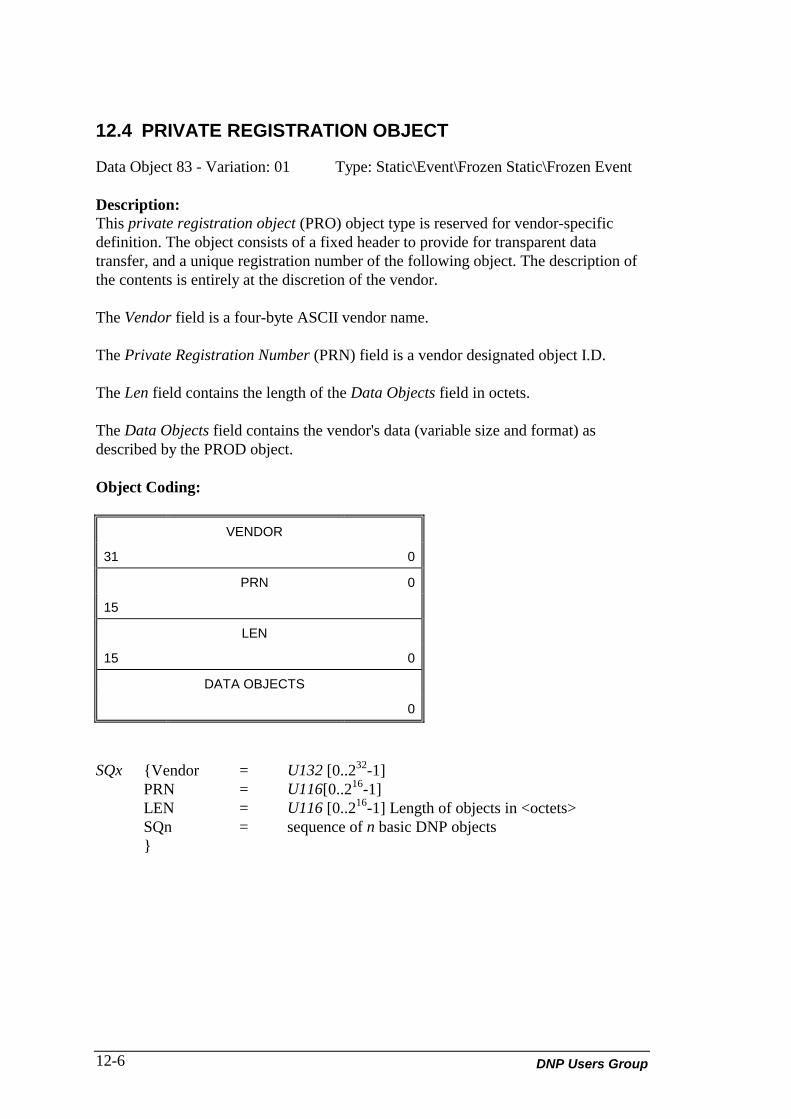
DNP Users Group12-6
12.4 PRIVATE REGISTRATION OBJECT
Data Object 83 - Variation: 01 Type: Static\Event\Frozen Static\Frozen Event
Description:This private registration object (PRO) object type is reserved for vendor-specificdefinition. The object consists of a fixed header to provide for transparent datatransfer, and a unique registration number of the following object. The description ofthe contents is entirely at the discretion of the vendor.
The Vendor field is a four-byte ASCII vendor name.
The Private Registration Number (PRN) field is a vendor designated object I.D.
The Len field contains the length of the Data Objects field in octets.
The Data Objects field contains the vendor's data (variable size and format) asdescribed by the PROD object.
Object Coding:
VENDOR
31 0
PRN 0
15
LEN
15 0
DATA OBJECTS
0
SQx {Vendor = U132 [0..232-1]PRN = U116[0..216-1]LEN = U116 [0..216-1] Length of objects in <octets>SQn = sequence of n basic DNP objects}

DNP V3.00 Data Object Library (Version 0.02) 12-7
12.5 PRIVATE REGISTRATION OBJECT DESCRIPTOR
Data Object 83 - Variation: 02 Type: Static
Description:This object type is reserved for vendor private registration object description. Theobject is matched one-to-one with its PRO object. The object consists of a fixedheader to provide for transparent data transfer, and a unique registration number of thefollowing object. The description of the contents is entirely at the discretion of thevendor.
The private registration object description (PROD) object maintains a one-to-onerelationship with the PRO object, and can be used to parse the PRO into basic DNPObjects for processing. The PROD consists of one element for each correspondingelement of the PRO. Each element consists in turn of a set of DNP object andvariation numbers.
The Vendor field is a four-byte ASCII vendor name.
The Private Registration Number (PRN) field is a vendor designated object I.D.
The Count field specifies the number of object definitions that follow this field. Eachobject definition consists of the three fields: quantity, object and variation.
The Quantity field specifies the number of objects, specified by the object andvariation fields, which will be found in the PRO object.
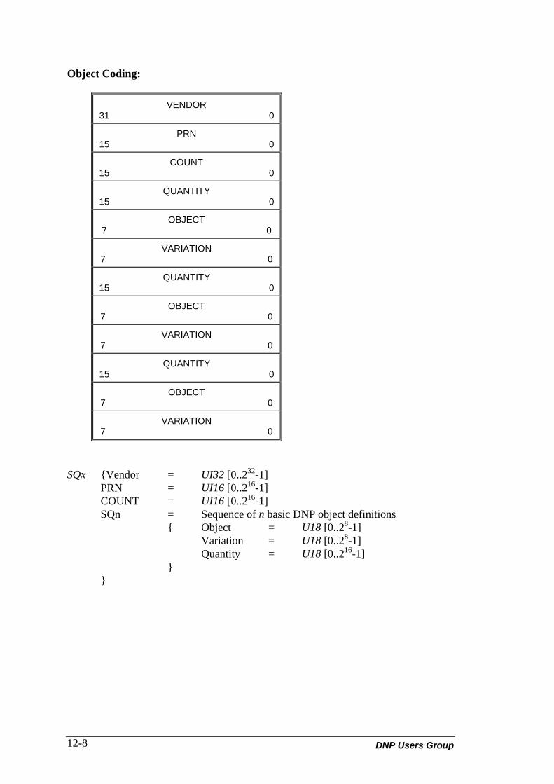
DNP Users Group12-8
Object Coding:
VENDOR31 0
PRN15 0
COUNT15 0
QUANTITY15 0
OBJECT7 0
VARIATION7 0
QUANTITY15 0
OBJECT7 0
VARIATION7 0
QUANTITY15 0
OBJECT7 0
VARIATION7 0
SQx {Vendor = UI32 [0..232-1]PRN = UI16 [0..216-1]COUNT = UI16 [0..216-1]SQn = Sequence of n basic DNP object definitions
{ Object = U18 [0..28-1]Variation = U18 [0..28-1]Quantity = U18 [0..216-1]
}}

DNP V3.00 Data Object Library (Version 0.02) 12-9
The following illustrations serve as examples for more clarification:
PROD:
(blank) B B A
0 16
0 3
2
1
2
2
21
2
5
30
1
In the above example:• B, B, and A, represent the vendor name.• PRN is private object #16 for vendor A B B.• Count specifies that three definitions follow, with each definition consisting of
quantity, object, and variation.

DNP Users Group12-10
The corresponding PRO object is:
(blank) B B A
0 16
0 33
binary input1
binary input2
Counter 1
Counter 2
Analog 1
Analog 2
Analog 3
Analog 4
Analog 5

DNP V3.00 Data Object Library (Version 0.02) 12-11


DNP V3.00 Data Object Library (Version 0.02) 13-1
13. APPLICATION OBJECTDEFINITIONS
This section defines the application data objects using the rules established in section2. DECLARATION RULES FOR INFORMATION ELEMENTS.
13.1 APPLICATION IDENTIFIER
Data Object 90 - Variation: 01
Description:The application identifier object is an information object used to represent anapplication or operating system process within a device. This object is used inconjunction with the application functions of the application layer to control softwareapplications.
This object has no defined format and is simply used as a place holder. The free-format qualifier of the application layer should be used to identify the application inquestion, or if the application is unknown, the ALL qualifier should be used to specifyall relevant applications.

DNP Users Group13-2
DNP V3.00 Data Object Library (Version 0.02) 14-1
14. ALTERNATE NUMERIC OBJECTDEFINITIONS
This section defines the alternate or custom numeric representation data objects usingthe rules established in section 2. DECLARATION RULES FOR INFORMATIONELEMENTS.
14.1 SHORT FLOATING POINT
Data Object 100 - Variation: 01
Description:The short floating point information object represents a calculated or measuredscientific value. The format of this object complies with the IEEE-754 standard forfloating-point number representation.
The value field holds the actual floating point number and follows the format for ashort real as specified by the IEEE-754 standard.
The flag field holds information about the point and has the same meaning as previousobjects.
The units field determines the units of the value field. This is the scientific orengineering units associated with the measured or calculated quantity.

DNP Users Group14-2
Object Coding:
Units7 0
Flag7 0
Value
Sign0 0
Exponent7 0
Significant22 0
FLAG ={On-line = BS1 [0] <0, off-line; 1, on-line>Restart = BS1 [1] <0, normal; 1, restart>Communication lost = BS1 [2] <0, normal; 1, lost>Remote forced data = BS1 [3] <0, normal; 1, forced>Local forced data = BS1 [4] <0>Over-range = BS1 [5] <0, normal; 1, over-range>Reference check = BS1 [6] <0, normal; 1, error>Reserved = BS1 [7] <0>}
Narrative:The absolute value can be derived from the value field as follows:
Absolute_Value = 1.s0 s1 s2 s3 s4 .. s22 x 2 (Exp -127)
where: si = Significant[i..i] and Exp= Exponent[0..7]
Sign: 0 if number is positive, and 1 if the number is negative.Exponent: Power of 2 applied to 1. Significant.Significant: Significant binary digits in value.

DNP V3.00 Data Object Library (Version 0.02) 14-3
The units field has the following defined values:0: Volts p-p (peak-to-peak voltage)1: Amperes p-p (peak-to-peak current)2: Volts RMS3: Amperes RMS4: KW or kilowatts (real power or volt-amps resistive)5: KVA or kilo volt-amps (volt-amps total)6: KVAR or kilovars (imaginary power or volt-amps reactive)7: KwH (kilowatt hours)8: KVARH (kiloVAR hours)9: PF (power factor)10: Hz (frequency in cycles per second)11: w (frequency in radians)12: C (degrees Celsius)13: F (degrees Fahrenheit)14: K (degrees Kelvin)15: N (force in Newtons)16: kg (mass in kilograms)17: m/s2 (acceleration)18: N/m2 (pressure in Newtons per square meter)19: N*m (torque in Newton-meters)

DNP Users Group14-4
14.2 LONG FLOATING POINT
Data Object 100 - Variation: 02
Description:The long floating point information object represents a calculated or measuredscientific value. The format of this object complies with the IEEE-754 standard forfloating-point number representation.
The value field holds the actual floating point number and follows the format for along real as specified by the IEEE-754 standard.
The flag field holds information about the point and has the same meaning as previousobjects.
The units field determines the units of the value field. This is the scientific orengineering units associated with the measured or calculated quantity.
Object Coding:
Units7 0
Flag7 0
Value
Sign0 0
Exponent10 0
Significant51 0
FLAG ={On-line = BS1 [0] <0, off-line; 1, on-line>Restart = BS1 [1] <0, normal; 1, restart>Communication lost = BS1 [2] <0, normal; 1, lost>Remote forced data = BS1 [3] <0, normal; 1, forced>Local forced data = BS1 [4] <0>Over-range = BS1 [5] <0, normal; 1, over-range>Reference check = BS1 [6] <0, normal; 1, error>Reserved = BS1 [7] <0>}

DNP V3.00 Data Object Library (Version 0.02) 14-5
Narrative:The absolute value can be derived from the value field as follows:
Absolute_Value = 1.s0 s1 s2 s3 s4 .. s51 x 2 (Exp -1023)
where: si = Significant[i..i] and Exp= Exponent[0..7]
Sign: 0 if number is positive, and 1 if the number is negative.Exponent: Power of 2 applied to 1. Significant.Significant: Significant binary digits in value.
The units field has the following defined values:0: Volts p-p (peak-to-peak voltage)1: Amperes p-p (peak-to-peak current)2: Volts RMS3: Amperes RMS4: KW or kilowatts (real power or volt-amps resistive)5: KVA or kilo volt-amps (volt-amps total)6: KVAR or kilovars (imaginary power or volt-amps reactive)7: KwH (kilowatt hours)8: KVARH (kiloVAR hours)9: PF (power factor)10: Hz (frequency in cycles per second)11: w (frequency in radians)12: C (degrees Celsius)13: F (degrees Fahrenheit)14: K (degrees Kelvin)15: N (force in Newtons)16: kg (mass in kilograms)17: m/s2 (acceleration)18: N/m2 (pressure in Newtons per square meter)19: N*m (torque in Newton-meters)
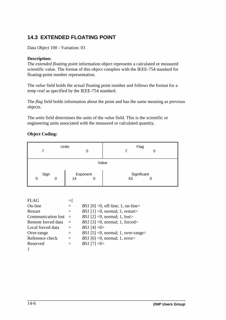
DNP Users Group14-6
14.3 EXTENDED FLOATING POINT
Data Object 100 - Variation: 03
Description:The extended floating point information object represents a calculated or measuredscientific value. The format of this object complies with the IEEE-754 standard forfloating-point number representation.
The value field holds the actual floating point number and follows the format for atemp real as specified by the IEEE-754 standard.
The flag field holds information about the point and has the same meaning as previousobjects.
The units field determines the units of the value field. This is the scientific orengineering units associated with the measured or calculated quantity.
Object Coding:
Units7 0
Flag7 0
Value
Sign0 0
Exponent14 0
Significant63 0
FLAG ={On-line = BS1 [0] <0, off-line; 1, on-line>Restart = BS1 [1] <0, normal; 1, restart>Communication lost = BS1 [2] <0, normal; 1, lost>Remote forced data = BS1 [3] <0, normal; 1, forced>Local forced data = BS1 [4] <0>Over-range = BS1 [5] <0, normal; 1, over-range>Reference check = BS1 [6] <0, normal; 1, error>Reserved = BS1 [7] <0>}

DNP V3.00 Data Object Library (Version 0.02) 14-7
Narrative:The absolute value can be derived from the value field as follows:
Absolute_Value = 1.s0 s1 s2 s3 s4 .. s51 x 2 (Exp -1023)
where: si = Significant[i..i] and Exp= Exponent[0..7]
Sign: 0 if number is positive, and 1 if the number is negative.Exponent: Power of 2 applied to 1. Significant.Significant: Significant binary digits in value.
The units field has the following defined values:0: Volts p-p (peak-to-peak voltage)1: Amperes p-p (peak-to-peak current)2: Volts RMS3: Amperes RMS4: KW or kilowatts (real power or volt-amps resistive)5: KVA or kilo volt-amps (volt-amps total)6: KVAR or kilovars (imaginary power or volt-amps reactive)7: KwH (kilowatt hours)8: KVARH (kiloVAR hours)9: PF (power factor)10: Hz (frequency in cycles per second)11: w (frequency in radians)12: C (degrees Celsius)13: F (degrees Fahrenheit)14: K (degrees Kelvin)15: N (force in Newtons)16: kg (mass in kilograms)17: m/s2 (acceleration)18: N/m2 (pressure in Newtons per square meter)19: N*m (torque in Newton-meters)

DNP Users Group14-8
14.4 SMALL-PACKED BINARY CODED DECIMAL
Data Object 101 - Variation: 01
Description:The small-packed binary coded decimal information object represents a sequence ofBCD digits. Each BCD digit can represent a variety of information from controloutputs to analog inputs.
Object Coding:
Digit 43 0
Digit 33 0
Digit 23 0
Digit 13 0
SPBCD = SQ4 {Digit1 = UI4 [0..3] <0..10>Digit2 = UI4 [0..3] <0..10>Digit3 = UI4 [0..3] <0..10>Digit4 = UI4 [0..3] <0..10>}

DNP V3.00 Data Object Library (Version 0.02) 14-9
14.5 MEDIUM-PACKED BINARY CODED DECIMAL
Data Object 101 - Variation: 02
Description:The medium-packed binary coded decimal information object represents a sequenceof BCD digits. Each BCD digit can represent a variety of information from controloutputs to analog inputs.
Object Coding:
Digit 43 0
Digit 33 0
Digit 23 0
Digit 13 0
Digit 83 0
Digit 73 0
Digit 63 0
Digit 53 0
MPBCD = SQ8 {Digit1 = UI4 [0..3] <0..10>Digit2 = UI4 [0..3] <0..10>Digit3 = UI4 [0..3] <0..10>Digit4 = UI4 [0..3] <0..10>Digit5 = UI4 [0..3] <0..10>Digit6 = UI4 [0..3] <0..10>Digit7 = UI4 [0..3] <0..10>Digit8 = UI4 [0..3] <0..10>}

DNP Users Group14-10
14.6 LARGE-PACKED BINARY CODED DECIMAL
Data Object 101 - Variation: 03
Description:The large-packed binary coded decimal information object represents a sequence ofBCD digits. Each BCD digit can represent a variety of information from controloutputs to analog inputs.
Object Coding:
Digit 43 0
Digit 33 0
Digit 23 0
Digit 13 0
Digit 83 0
Digit 73 0
Digit 63 0
Digit 53 0
Digit 123 0
Digit 113 0
Digit 103 0
Digit 93 0
Digit 163 0
Digit 153 0
Digit 143 0
Digit 133 0
LPBCD = SQ16 {Digit1= UI4 [0..3] <0..10>Digit2= UI4 [0..3] <0..10>Digit3= UI4 [0..3] <0..10>Digit4= UI4 [0..3] <0..10>Digit5= UI4 [0..3] <0..10>Digit6= UI4 [0..3] <0..10>Digit7= UI4 [0..3] <0..10>Digit8= UI4 [0..3] <0..10>Digit9= UI4 [0..3] <0..10>Digit10= UI4 [0..3] <0..10>Digit11= UI4 [0..3] <0..10>Digit12= UI4 [0..3] <0..10>Digit13= UI4 [0..3] <0..10>Digit14= UI4 [0..3] <0..10>Digit15= UI4 [0..3] <0..10>}
DNP V3.00 Data Object Library (Version 0.02) 1
LIST OF ABBREVIATIONS ANDACRONYMS
ASCII American Standard Code for Information Interchange
BCD binary coded decimalBINBS bit string
CRC cyclic redundancy checkCTO common time objectCTO common time of occurrenceCWD change working directory
DA distributed automationDAC data acquisition and controlDNP Distributed Network Protocol
EBCDIC extended binary coded decimalEXEC execute
F fixed pointFIFO first-in-first-out
I integerID identificationIEC International Electrotechnical CommissionIEEE Institute of Electrical and Electronics Engineers
LEN lengthLPBCD large-packed binary coded decimal
MPBCD medium-packed binary coded decimalMSEC millisecond
OS octet string

DNP Users Group2
PCB pattern control blockPRN private registration numberPRO private registration objectPROD private registration object descriptionPWD (return to) present working directory
R realRESP responseRMS root mean squared
SCADA supervisory control and data acquisitionSPBCD small-packed binary coded decimal
UF unsigned fixed pointUI unsigned integer