DNC 60 PS - Főoldal vezerlok/cybelec_N60ps_en.pdf · DNC 60 PS User Guide CYBELEC SA Tel. ++ 41 24...
97
DNC 60 PS User Guide CYBELEC SA Tel. ++ 41 24 447 02 00 RUE DES UTTINS 27 Fax ++ 41 24 447 02 01 CH - 1400 YVERDON-LES-BAINS E-Mail: [email protected] SWITZERLAND V-DOC-60PS-EN
Transcript of DNC 60 PS - Főoldal vezerlok/cybelec_N60ps_en.pdf · DNC 60 PS User Guide CYBELEC SA Tel. ++ 41 24...
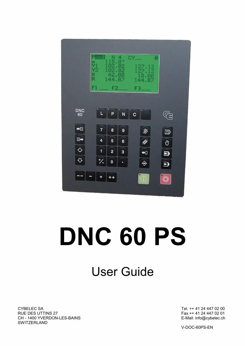
DNC 60 PS
User Guide
CYBELEC SA Tel. ++ 41 24 447 02 00 RUE DES UTTINS 27 Fax ++ 41 24 447 02 01 CH - 1400 YVERDON-LES-BAINS E-Mail: [email protected] SWITZERLAND V-DOC-60PS-EN
CYBELEC SA Tel. ++ 41 24 447 02 00 RUE DES UTTINS 27 Fax ++ 41 24 447 02 01 CH - 1400 YVERDON-LES-BAINS E-Mail: [email protected] SWITZERLAND V-DOC-60PS-EN

Information in this document is subject to change without notice, and does not represent a commitment on the part of CYBELEC SA. The software described in this document is furnished under a license agreement or nondisclosure agreement. The software may be used or copied only in accordance with the terms of the agreement. It is against the law to copy the software on any medium except as specifically allowed in the license or nondisclosure agreement.
Copyright CYBELEC SA. 1991
All rights reserved.
Important:
This notice explains normal and standard programming operations for the numerical control. In view of the fact that numerical controls can be equipped with configurable functions by the press manufacturer for his own specific purposes, please refer to the manufacturer-supplied complementary instructions regarding the programming of these functions.
Autocad is a registered trade mark of Autodesk Inc..
CYBELEC is a registred trademark of CYBELEC SA.
Ethernet is a registered trade mark of Xerox Corporation.
IBM , PC/AT , PC Network , Token Ring Network are registered trade marks of the International Business Machines Corporation.
MS-DOS is a registered trade mark of Microsoft Corporation.
MS-Windows is a registered trade mark of Microsoft Corporation.
Novell Netware is a registered trade mark of Novell, Incorporated.
Windows NT is a registered trade mark of Microsoft Corporation.
SAFETY AND MAINTENANCE INSTRUCTIONS PAGE I
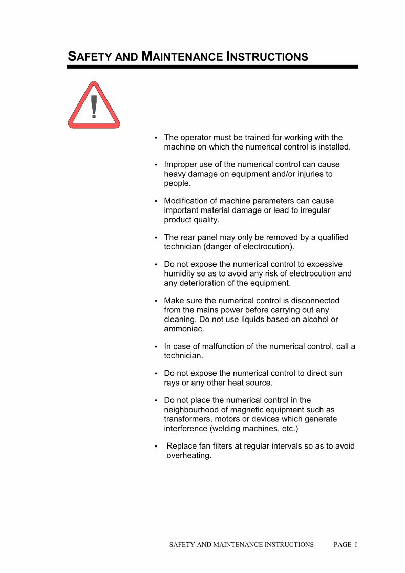
SAFETY AND MAINTENANCE INSTRUCTIONS
! The operator must be trained for working with the machine on which the numerical control is installed.
! Improper use of the numerical control can cause heavy damage on equipment and/or injuries to people.
! Modification of machine parameters can cause important material damage or lead to irregular product quality.
! The rear panel may only be removed by a qualified technician (danger of electrocution).
! Do not expose the numerical control to excessive humidity so as to avoid any risk of electrocution and any deterioration of the equipment.
! Make sure the numerical control is disconnected from the mains power before carrying out any cleaning. Do not use liquids based on alcohol or ammoniac.
! In case of malfunction of the numerical control, call a technician.
! Do not expose the numerical control to direct sun rays or any other heat source.
! Do not place the numerical control in the neighbourhood of magnetic equipment such as transformers, motors or devices which generate interference (welding machines, etc.)
! Replace fan filters at regular intervals so as to avoid overheating.

PAGE II USER GUIDE DNC 60 PS
This page has been left blank intentionally.

LICENSE AGREEMENT PAGE III
LICENSE AGREEMENT FOR CYBELEC SOFTWARE
GENERAL COPYRIGHT
The CYBELEC software is protected by Copyright, and all the copying rights are reserved.
The CYBELEC software may only be installed and used in authorized equipments (PC or DNC).
The user manuals are also covered by copyright, and all rights to use and to copy are reserved.
This document may not, in whole or in part, be copied, photocopied, reproduced, translated or reduced without prior consent, in writing, from CYBELEC.
SPECIAL DISKETTE COPYRIGHT
The legal users of this software product are authorized only to copy the contents of the diskette into the memory of the computer to run the program, and to make one backup copy of the original diskette for safety purposes in case of loss of the original program.
Unauthorized copying, duplicating, selling or otherwise distributing this product is a violation of the law.
SPECIAL EPROM COPYRIGHT
The CYBELEC DNC and CNC units in which the original software made by CYBELEC has been replaced by a copy not made by CYBELEC, and without written authorization of CYBELEC, will immediately lose their warranty.
WARRANTY
CYBELEC does not warrant that its software products will function properly in every computer and programming environment.
The limitations of use of a software product and its technical specifications are decided by CYBELEC only; CYBELEC solely is entitled to decide upon conformity and performance of a given software.
The CYBELEC software does not compensate for incompatibilities in operating system revisions or versions.
Running the CYBELEC software under various revisions or versions, or switching between different versions or revisions may result in loss or alteration of data.
PAGE IV LICENSE AGREEMENT
SOFTWARE UPDATE SERVICE
Purchase of the CYBELEC software entitles the user, during one year, to delivery of software updates of the "correction" type.
During the use of a revised or corrected version of the software it may occur that data (program, parameters, etc.) is lost, or that the equipment or its connections need to be modified; these effects are not always foreseeable and do not engage CYBELEC's responsibility.
TERMINATION
This agreement shall automatically terminate upon any act of bankruptcy by or against licensee, upon any assignment for the benefit of creditors of the licensee, upon any attachment execution of judgement or process against licensee or its assets that substantially inhibits its ability to do business, or upon dissolution of licensee.
CYBELEC has the right to terminate this agreement immediately, should the licensee violate the aforementioned conditions.
Within 30 days of termination of this agreement for any reason, licensee shall at his option, either:
! return to CYBELEC or authorized dealer all existent copies of such software and related materials, or
! furnish to CYBELEC evidence satisfactory that the original and all copies of the software, in whole and in any form, have been destroyed.
LIMITATION OF LIABILITY
The foregoing warranty is instead of all other warranties, expressed or implied.
Licensee further agrees that CYBELEC shall not be liable for any lost profits, lost savings, loss of use, or other incidental or consequential damages arising from the use or inability to use the software, or for any claim or demand against licensee by any other party.
In no event shall CYBELEC be liable for consequential damages, even if CYBELEC has been advised of the possibility of such damages.
CYBELEC does not warrant that the functions contained in the software will meet the licensee's requirement or that the operation of the software will be totally error free.
Should the software prove defective, the licensee (and not CYBELEC or an authorized dealer or representative) will assume the entire cost of all necessary service, repair or correction.
CYBELEC warrants the diskettes, EPROMS or other magnetic support or cassettes on which the programs are supplied to be free of defects in material and workmanship under normal use for a period of 90 days from the date of shipment to the licensee as evidenced by a copy of the packing slip.

LICENSE AGREEMENT PAGE V
LIMITATION OF REMEDIES
CYBELEC's entire liability and the licensee's exclusive remedy shall be as follows:
The replacement of any diskettes or EPROMS or magnetic support media or cassettes not meeting CYBELEC's limited warranty and which materials are returned to CYBELEC or an authorized CYBELEC representative with a copy of the packing slip, or
If CYBELEC or its representative is unable to deliver replacement diskettes, magnetic support media, EPROM or cassettes which are free of defects in materials or workmanship, the licensee may terminate this agreement under the terms and conditions herein mentioned, and the purchaser's money will be refunded.
GENERAL
The licensee acknowledges that he has read this agreement, understands it and agrees to be bound by its terms and conditions.
The licensee agrees to hold CYBELEC harmless on all liability associated with licensee's breach of this agreement including, but not limited to, all reasonable attorney's fees and court costs, if any.
This license agreement shall be governed by Swiss law; place of jurisdiction is Lausanne, Switzerland.
MAINTENANCE
CYBELEC will provide one year of software maintenance.The extent of maintenance, and response time for furnishing same, shall be at the sole discretion of CYBELEC.Maintenance shall normally include correction of errors in code, correction of errors in supporting documentation, update versions of the covered software which may be released by CYBELEC during the maintenance period.
In no event shall CYBELEC be obliged to provide technical support in attempting to resolve problems or difficulties resulting from licensee's modification of the licensed software; any such modification by licensee is entirely at licensee's own risk.

PAGE VI LICENSE AGREEMENT
This page has been left blank intentionally.
23.01.2001 V. 1.2
N60PS_EN.DOC CONTENTS PAGE 1
CONTENTS
SAFETY AND MAINTENANCE INSTRUCTIONS............................................................................I
LICENSE AGREEMENT FOR CYBELEC SOFTWARE ..................................................................III Safety, Copyright & License agreement ..............................................................................3
CONVENTIONS ...............................................................................................................................5 Typographical conventions ..................................................................................................5 Abbreviations / glossary.......................................................................................................5
DESCRIPTION OF THE DNC 60 PS...............................................................................................7 General information .............................................................................................................7 Technical characteristics .....................................................................................................8
ACCESSORIES................................................................................................................................11
THE USER INTERFACE..................................................................................................................13 The screen...........................................................................................................................13 The keyboard.......................................................................................................................13
THE MAIN MENU.............................................................................................................................19 Choices of the main menu...................................................................................................19
PROGRAMMING .............................................................................................................................21 Programming on the L-alpha page......................................................................................23 L-alpha method....................................................................................................................27 Definition of the bending order ............................................................................................30
THE SEQUENCE PAGE ..................................................................................................................37 Programming on the sequence page ..................................................................................40
PRODUCT MANAGEMENT.............................................................................................................45 List of products ....................................................................................................................45
TOOL PROGRAMMING...................................................................................................................49 Punch / Die programming....................................................................................................50
TRANSFER ......................................................................................................................................53 Tests of the serial ports .......................................................................................................54 LINK 7000 / CYBACK..........................................................................................................55

PAGE 2 CONTENTS
THE MACHINE WORKING MODES............................................................................................... 57 Adjustment mode................................................................................................................ 57 Sensitive mode ................................................................................................................... 58 Automatic mode.................................................................................................................. 58
PROTECTION OF THE ACCESS LEVELS .................................................................................... 59 General Information ............................................................................................................ 59 The users............................................................................................................................ 60 Access by password ........................................................................................................... 61 Access to levels superior to 3 ............................................................................................. 62 Change password ............................................................................................................... 63 Management of the access levels by external key ............................................................. 64
ANNEXES........................................................................................................................................ 65 The INITIALIZATION page ................................................................................................. 65 The tool reference............................................................................................................... 67 The contact point (CP) or Pinch point................................................................................. 70 The gauge axes .................................................................................................................. 71 Programming the axes datum ............................................................................................ 75 Calibration........................................................................................................................... 75 Ideal curve .......................................................................................................................... 77 Cycle without bend.............................................................................................................. 79 Punching ............................................................................................................................. 79 Bottoming............................................................................................................................ 80 Angle correction .................................................................................................................. 80 Alphanumerical characters ................................................................................................. 82 Messages / Errors............................................................................................................... 82 The interactive messages................................................................................................... 83 Print of the current screen .................................................................................................. 86
INDEX.............................................................................................................................................. 87

FOREWORD PAGE 3
SAFETY, COPYRIGHT & LICENSE AGREEMENT
Please consult the safety instructions, copyright and license agreement on the first pages of the manual.
ABOUT THIS MANUAL
This manual is designed to help the user to familiarize with the numerical control DNC 60 and to use it with a maximum of efficiency.
To reach a maximum of comfort and productivity of the numerical control, it is recommended to read attentively the whole manual.
A table of contents and a well organized index enable you to find rapidly the searched subject.
How to get rapidly acquinted with the numerical control ? Follow the rabbit. It will pass through the important stages and will guide you in the programming of an example product.
Remark: In this User Guide it is assumed that the DNC has an operational configuration (i.e. machine parameters and tools are programmed).
Go to page 21.
This manual is evolutive. You, the user, can help us to give you better assistance. If you have any remarks on this document, please write us to:
CYBELEC S.A. Dpt Communication Rue des Uttins 27
CH-1400 Yverdon-les-Bains Fax ++ 41 24 447 02 01
E-mail: [email protected]

PAGE 4 FOREWORD
This page has been left blank intentionally.

CONVENTIONS PAGE 5
CONVENTIONS
As a general rule, in this manual we will not repeat how to validate a field, select a tool, call a page or any other basic manipulations. These informations are described at the beginning of this manual.
TYPOGRAPHICAL CONVENTIONS
Arial bold Quotations of text as seen on the screen.
Arial bold italic Used to indicate the name of a DNC input or output.
Italic Reference to a written element, a paragraph or a manual. For example: See Conventions.
ABBREVIATIONS / GLOSSARY
Explications of the abbreviations which are not visible fields in the pages of the numerical control.
TDC Top dead centre.
SWP Switch point of speed, i.e. the change from approach speed in bending speed in the descent phase.
PSS Safety point. This point is calculated in function of the tools height and the material thickness.
CP Contact point (see page 70).
BDC Bottom dead centre
LED Light Emitting Diode. Small red light serving as luminous indicator.

PAGE 6 USER GUIDE DNC 60 PS
This page has been left blank intentionally.
DESCRIPTION OF THE DNC 60 PS PAGE 7
DESCRIPTION OF THE DNC 60 PS
GENERAL INFORMATION
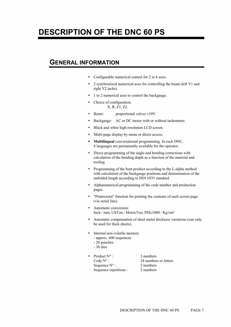
! Configurable numerical control for 2 to 6 axes.
! 2 synchronized numerical axes for controlling the beam (left Y1 and right Y2 jacks).
! 1 to 2 numerical axes to control the backgauge.
! Choice of configuration: X, R, Z1, Z2.
! Beam: proportional valves ±10V.
! Backgauge: AC or DC motor with or without tachometer.
! Black and white high resolution LCD screen.
! Multi-page display by menu or direct access.
!!!! Multilingual conversational programming. In each DNC, 8 languages are permanently available for the operator.
! Direct programming of the angle and bending corrections with calculation of the bending depth as a function of the material and tooling.
! Programming of the bent product according to the L-alpha method with calculation of the backgauge positions and determination of the unfolded length according to DIN 6935 standard.
! Alphanumerical programming of the code number and production pages.
! "Printscreen" function for printing the contents of each screen page (via serial line).
! Automatic conversion: Inch / mm; USTon / MetricTon; PSIx1000 / Kg/cm²
! Automatic compensation of sheet metal thickness variations (can only be used for thick sheets).
! Internal non-volatile memory - approx. 600 sequences - 20 punches - 30 dies
! Product N° : 3 numbers Code N° : 24 numbers or letters Sequence N° : 2 numbers Sequence repetitions : 2 numbers

PAGE 8 USER GUIDE DNC 60 PS
! Machine parameters in 8 languages: Limitation of axes displacement, safety, adjustment of servomechanisms, etc.
! Beam positioning in high precision closed loop with control of speed, pressure and parallelism.
! For each digital axis: High performance closed loop regulation with or without insensibility zone. - Counting frequency: 250 KHz - Displacement speed, acceleration, deceleration, regulation gain,
PID, safeties and limit switches programmable numerically in the machine parameters.
- Automatic initialization procedure.
! Memorization of the back gauge positions in the case of a power failure.
! Corrections per product and per sequence for the axes.
! RS232 series interface (in option).
TECHNICAL CHARACTERISTICS
BENDING DEPTH (Y1 AND Y2 AXES)
Positioning range : 0 - 900,000 mm
Programmable resolution : 0,01 or 0,005 mm
Reproducibility : 0,002 mm
Ascent / descent beam speed : 150 mm/s
Bending speed : 1 - 50 mm/s (programmable)
Corrections per product and per sequence : 0 - ±99,99 mm
BACKGAUGE (X AXIS)
Positioning range : 0 - 2000,000 mm
Programmable resolution : 0,1 or 0,01 mm
Reproducibility : 0,02 mm
Displacement speed : 500 mm/s
Corrections per product and per sequence : 0 - ±99,99 mm
DESCRIPTION OF THE DNC 60 PS PAGE 9
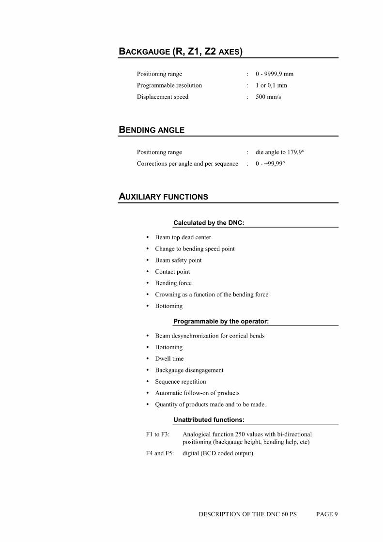
BACKGAUGE (R, Z1, Z2 AXES)
Positioning range : 0 - 9999,9 mm
Programmable resolution : 1 or 0,1 mm
Displacement speed : 500 mm/s
BENDING ANGLE
Positioning range : die angle to 179,9°
Corrections per angle and per sequence : 0 - ±99,99°
AUXILIARY FUNCTIONS
Calculated by the DNC:
! Beam top dead center
! Change to bending speed point
! Beam safety point
! Contact point
! Bending force
! Crowning as a function of the bending force
! Bottoming
Programmable by the operator:
! Beam desynchronization for conical bends
! Bottoming
! Dwell time
! Backgauge disengagement
! Sequence repetition
! Automatic follow-on of products
! Quantity of products made and to be made.
Unattributed functions:
F1 to F3: Analogical function 250 values with bi-directional positioning (backgauge height, bending help, etc)
F4 and F5: digital (BCD coded output)

PAGE 10 USER GUIDE DNC 60 PS
THE MEMORIES
A SRAM memory allows the programming and storing of products, tools and machine parameters. A lithium battery conserves the data during about 10 years.
Work memory (or buffer)
This memory is used for programming, modifying and executing products. It is a temporary memory whose contents are deleted whenever another product is called for.
The contents of this memory is conserved if the DNC power supply is cut, even if it has not been previously stored in the internal memory.
Internal memory
Sometimes called internal cassette, this fixed internal memory, of the static RAM type maintained by a lithium battery, contains the products, tools, axes positions, numbers concerning the production and machine parameters. No programming or modification are done directly in this memory.
Flash memory
The DNC 60 is equipped with a Flash memory including the program and the cycle of the numerical control. The machine cycle can be updated by means of the serial link RS232 (option).
DESCRIPTION OF THE DNC 60 PS PAGE 11
ACCESSORIES
CYBACK Software for storage in PC. Allows the storage and recall of data (products, tools, machine parameters) for the DNC 7000, DNC 70, and DNC 30 CNCs in a PC via the serial line. Up to 10 different CNCs can be selected. Ask for our "Product information" about CYBACK.
PC900 / PC1200 PC900 is a DOS program, PC1200 a Windows program. This software allows to program on a PC in 2 and 3 dimensions the products to be realized on the numerical control. This software executes the simulation and graphic display of the bending order taking into account the characteristics of the machine, the tools and the material.
An option (LINK7000, see below) allows to transfer products to the DNC 7000, DNC 70, DNC 50 and DNC 60.
LINK7000 Option of the software PC900 / PC1200 to transfer products to the DNC 7000, DNC 70, DNC 50 or DNC 60 by the serial line.

PAGE 12 USER GUIDE DNC 60 PS
This page has been left blank intentionally.

THE USER INTERFACE PAGE 13
THE USER INTERFACE
THE SCREEN
The screen displays the products, tools and machine parameters as well as all other useful information for programming and machine work.
The keys situated on the front of the DNC are used for selecting the screen pages and introducing data.
A cursor indicates where the user can intervene.
On all pages, when first displayed the cursor is located on the programmable field on which it was placed during the last intervention on that page.
The cursor can be moved to the previous or following field by pressing the
or key.
Faster Regardless of the cursor position on the page , pressing the and the
keys simultaneously moves the cursor to the first programmable field of the page.
THE KEYBOARD
The keyboard is divided into six zones:
! Numerical keyboard
! Screen page selection keys
! Working mode zone
! The commands
! The cursor keys
! The manual mode keys
NUMERICAL KEYBOARD
The numerical keys as well as the and keys are used to introduce numbers or values into the different fields.

PAGE 14 USER GUIDE DNC 60 PS
THE SCREEN PAGE SELECTION KEYS
Main menu key Gives access to the MAIN MENU page.
Product list key Double function key. Pressing this key once displays the list of products in the DNC memory. Pressing the key again displays the search for products by criteria page.
Product key Triple function key. Pressing this key once displays the angle length (L-alpha) values. Pressing a second time displays the bending order with their respective legs. Pressing a third time displays the bending values which are calculated as a function of the values introduced on the previous page.
Sequence key Triple function key. Pressing the key once displays all the values and functions of the current sequence. Pressing a second time displays the first page of values in large characters. Pressing a third time displays the second page of values and functions in large characters.
Correction key This key displays the correction page which allows to make corrections to the current sequence, as well as to the entire product.
THE USER INTERFACE PAGE 15
THE WORKING MODES
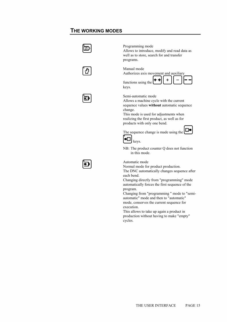
Programming mode Allows to introduce, modify and read data as well as to store, search for and transfer programs.
Manual mode Authorizes axis movement and auxiliary
functions using the keys.
Semi-automatic mode Allows a machine cycle with the current sequence values without automatic sequence change. This mode is used for adjustments when realizing the first product, as well as for products with only one bend.
The sequence change is made using the
keys.
NB: The product counter Q does not function in this mode.
Automatic mode Normal mode for product production. The DNC automatically changes sequence after each bend. Changing directly from "programming" mode automatically forces the first sequence of the program. Changing from "programming " mode to "semi-automatic" mode and then to "automatic" mode, conserves the current sequence for execution. This allows to take up again a product in production without having to make "empty" cycles.

PAGE 16 USER GUIDE DNC 60 PS
THE COMMANDS
Delete key Allows to delete a sequence or a program when the cursor is placed on the PRODUCT or N fields. Only functions in programming mode.
Clear key This key allows to delete data indicated by the cursor. Caution: pressing this key twice, on most pages, deletes all the data on the page.
Search key According to the cursor position allows: - to search for a product - to search for a sequence - to search for a tool - to search for a screen page - to start a product feasibility calculation - to transform L-alpha values into machine values - to calculate the unfolded length of the sheet - to execute a transfer Only functions in programming mode.
Store / insert / teach key Depending on the cursor position, allows to store the current program in the DNC internal memory, or create (insert) a new sequence in the middle of an existing program, or copy (teach) the value of an axis positioned manually in the current sequence. This key is only valid in programming (memorization and insertion) mode and in manual (teach) mode.

THE USER INTERFACE PAGE 17
THE CURSOR KEYS
Sequence forwards / Page forwards key This key allows to scroll pages of the same type. Also allows to pass to the next page when a series of information occupies several pages. Eg.: program sequence punch-die pages production pages parameter pages
In programming mode also allows to create an identical sequence (copy function) to the previous one as long as this is the last sequence of the program. The incorporated LED indicates whether the sequence is the last of the program.
Page backwards / Sequence backwards key
Inversed function of the key. Allows to scroll backwards through pages of the same type. Functions in all modes except automatic mode.
Cursor upwards, to the next accessible field.
Cursor downwards, to next accessible field.
and This key combination positions the cursor in the upper part of the current page.
PAGE 18 USER GUIDE DNC 60 PS
"MANUAL" ZONE
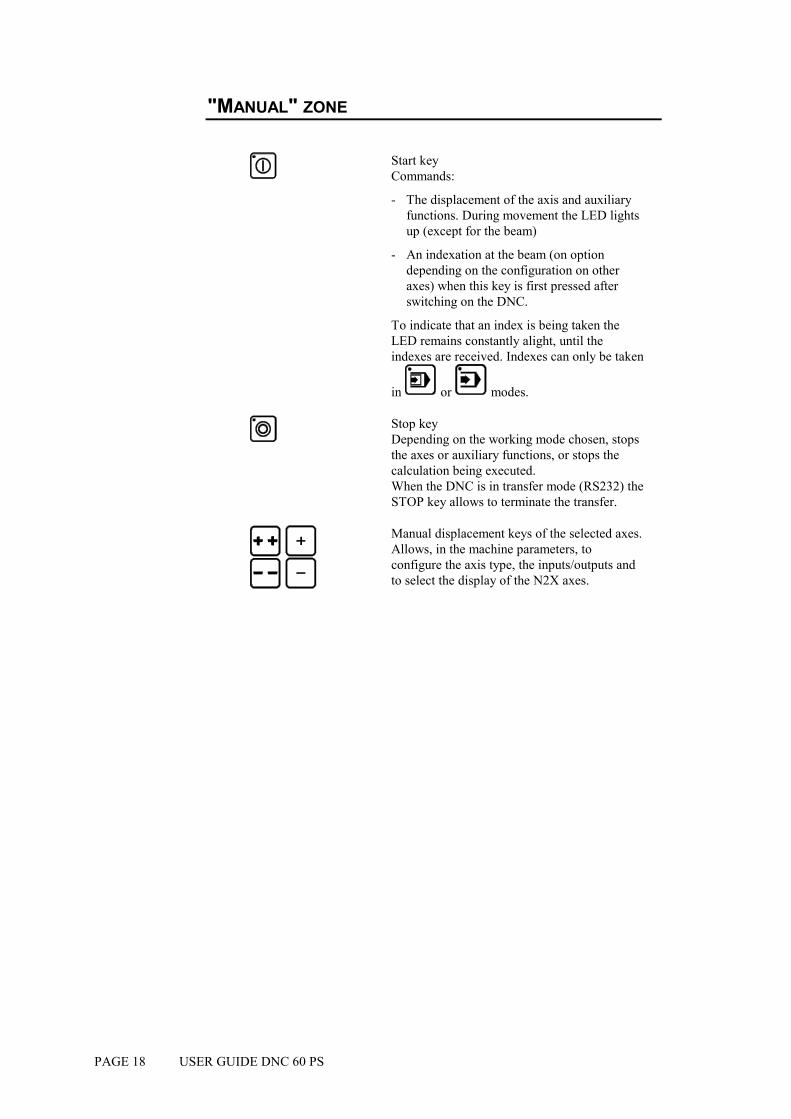
Start key Commands:
- The displacement of the axis and auxiliary functions. During movement the LED lights up (except for the beam)
- An indexation at the beam (on option depending on the configuration on other axes) when this key is first pressed after switching on the DNC.
To indicate that an index is being taken the LED remains constantly alight, until the indexes are received. Indexes can only be taken
in or modes.
Stop key Depending on the working mode chosen, stops the axes or auxiliary functions, or stops the calculation being executed. When the DNC is in transfer mode (RS232) the STOP key allows to terminate the transfer.
Manual displacement keys of the selected axes. Allows, in the machine parameters, to configure the axis type, the inputs/outputs and to select the display of the N2X axes.

THE MAIN MENU PAGE 19
THE MAIN MENU
By pressing the key on the top right of the keyboard, the main menu appears.
CHOICE ? __ 1 LIST OF PRODUCTS DNC / CRITERIA 2 3 LIST OF PUNCHES 4 LIST OF DIES 5 6 PROGR. PUNCHES / DIES 7 PRODUCT PUNCHES / DIES
8 PRODUCT STATUS; L; 9 PRODUCT BENDS; STOPS
10 PRODUCT X; ;Y 11 PROGR.AXES ORIGINS 12 TRANSFER DNC <-> PC 13 MACHINE PARAMETERS 14 MACHINE CONTROL
Regardless of which screen page you are on, you can always gain access to
the main menu by the key, which allows you to circulate in the different pages.
The option desired is chosen by entering the option number in the CHOICE
field on the first line of the screen and pressing the search key.
CHOICES OF THE MAIN MENU
1 DNC PRODUCT LIST / CRITERIA
This double page displays the list of products in the DNC memory and allows selective searching of products.
3 PUNCH LIST Displays the list of the punches.
4 DIE LIST Displays the list of thedies.
6 PUNCH / DIE PROGR.
From this page, it is possible to recall, program or delete a die or a punch.

PAGE 20 USER GUIDE DNC 60 PS
7 PRODUCT PUNCHES / DIES
This page allows to modify, for the product only, the reference of a tool.
8 PRODUCT STATUS; L;
Generally called L-alpha page, this page displays and allows the programming of products in "lengths and angles" mode.
9 PRODUCT BENDS;LEGS
Displays the page allowing to program or modify the bending order.
10 PRODUCT X; ; Y
Displays for each sequence the calculated axis position.
11 PROGR. AXES ORIGINS
Allows to program the axis position counter.
12 TRANSFER DNC <-> PC
Allows the global or partial two way transfer of products, tools or machine parameters between the fixed internal memory and a PC.
13 MACHINE PARAMETERS
Displays a series of pages which allow to introduce, display and modify the machine parameters.
14 MACHINE CONTROLS
Page allowing to control and to modify the state of certain inputs and outputs.

PROGRAMMING PAGE 21
PROGRAMMING
In this manual, it is being assumed that the DNC is configurated in such a way to be operational (i.e. the tools and machine parameters have already been programmed).
2 programming methods are accessible by the operator.
With unfolding calculation
! The L-alpha method. The L-alpha method allows to enter a profile to be bended with the external dimensions and angles of each face. The DNC calculates the unfolded length. After having programmed the bending order, the DNC will calculate the stop positions.
The faster method
! The direct programming. The direct programming is the fastest method for an experimented operator, for the whole programming of the product is done on the same page. It enables to directly program the axes' positions, and it calculates the bending depth as a function of the introduced angle.
Before starting to program a product, make sure that the tools necessary to make the product exist in the DNC memory and write down the numbers of the punches and dies to be used.
To do this proceed as described below: If you are already familiar with the tools present in the DNC, you may pass directly to chapter Programming on the L-alpha page, page 23).

PAGE 22 USER GUIDE DNC 60 PS
Consulting the list of punches
! On the main menu (reached by ), choose LIST OF PUNCHES.
Introduce for that 3 in the CHOICE field and press the search key.
LIST p/d 1/ 1 p/d 1/__ __/__ __/__ __/__ PUNCH p 90° ___° ___° ___° hp 100.00 ___.__ ___.__ ___.__ rp 1.50 ___.__ ___.__ ___.__ TON/M 100 ___ ___ ___ DIE Ve ___.__ ___.__ ___.__ ___.__ d ___° ___° ___° ___° hd ___.__ ___.__ ___.__ ___.__ rd ___.__ ___.__ ___.__ ___.__ TON/M ___ ___ ___ ___ REF Y ___.__ ___.__ ___.__ ___.__ SAF X ___.__ ___.__ ___.__ ___.__
! The list of punches available in the DNC appears, with the name of each punch and its characteristics (angle, height and radius).
! Note the number of the most appropriate punch.
If you don't find a punch which corresponds to your needs, you can create one.
In this case refer to chapter Tool programming, page 49.
It is possible, if more than four punches are programmed to see them by
pressing the key.
Consulting the list of dies
Proceed in the same way as described above for punches; access from the main menu LIST OF DIES.
Pass to page 27 or page 40, depending on the chosen programming method.

PROGRAMMING PAGE 23
PROGRAMMING ON THE L-ALPHA PAGE
The PRODUCT STATUS page is often called L-alpha page for its programming method. On this page, a product is programmed by defining its profile by the length and the angle of each face.
Call the L-alpha page using the key, or by passing via the main menu choosing PRODUCT STATUS.
This page presents as follows:
P 0 P+ ___ N 1 I/mm CODE CAL_/__.__ p/d __/__ St:_ Al:_ SS:_ Th: __.__ Kg/mm² ___.___ Lmat _____ Dev L ____.__ -N- -L- - - -p/d- -ri- CR TOL 1 ____.__ ____._°__/__ ____.__ __ ___ 2 ____.__ ____._°__/__ ____.__ __ ___ 3 ____.__ ____._°__/__ ____.__ __ ___ 4 ____.__ ____._°__/__ ____.__ __ ___ 5 ____.__ ____._°__/__ ____.__ __ ___ 6 ____.__ ____._°__/__ ____.__ __ ___ 7 ____.__ ____._°__/__ ____.__ __ ___ 8 ____.__ ____._°__/__ ____.__ __ ___ 9 ____.__ ____._°__/__ ____.__ __ ___ 10 ____.__ ____._°__/__ ____.__ __ ___
Remark: On the following pages, you will find a systematic explication of all the fields which figure on the L-alpha page. If you wish to just follow the procedure, you may pass directly to chapter L-alpha method, page 27.
L-ALPHA PAGE: EXPLICATION OF THE FIELDS
P Product number - existent in the work memory or - to be created or - to be searched for
The product number must be a number of a maximum of 3 digits between 1 and 997. (998 and 999 are reserved numbers)
If the product is created from an empty page, the field contains the number 0. The field keeps this value as long as the product has not been stored.
PAGE 24 USER GUIDE DNC 60 PS
P+ Number of the next product which will be
executed automatically. If this field is left empty, when the last sequence of the product is executed, the program will return to the first sequence of the current product. If it contains a product number, it will be executed immediately at the end of the current product. This allows to follow on several programs one after another. Do not forget to program in the last program the number of the first program in order to close the loop.
N Number of the current sequence, whose axe's values are displayed on the sequence page.
I/mm Allows to choose the unit of length. Programmed at 1, the face length values are expressed in Inches. Not programmed or programmed with a value other than 1, the data is displayed in millimeters.
CODE Code name or number (facultative), allowing to associate supplementary information with the product number in order to facilitate product management and searching. For the introduction of alphanumerical characters, see Alphanumerical characters, page 82.
CAL Allows automatic compensation of variations in sheet metal thickness. For programming this field, refer to chapter Calibration, page 75.
p/d Punch and die of the current product.
St: Choice of product material, steel, aluminium or Al: stainless steel. S.S.: Program 1 in the field next the material used.
If no field is programmed, steel is used by default.
Th: Material thickness.
Kg/mm² (Sigma) Tensile strength.
Lmat Bending length.
Dev L Unfolded length of the product calculated by the system according to DIN 6935 standard.

PROGRAMMING PAGE 25
L-alpha page : Explication of the columns
Each line (except the last) of the table on the PRODUCT STATUS page represents data related to one bend.
-N- -L- - - -p/d- -ri- CR TOL 1 ____.__ ____._°__/__ ____.__ __ ___ 2 ____.__ ____._°__/__ ____.__ __ ___ 3 ____.__ __
-N- Automatic numbering of the faces. A "face" is defined as being that part of the sheet metal situated between two bends or between the edge of the sheet and a bend. The maximum number of faces which can be programmed for a product is 14. If more sequences are needed, use the chaining of product function (see previous page, field P+).
-L- Face length. Designates the distance between two bends or the distance between the edge of the sheet and the first bend.
80.00 60.00 80.00 85.00 120.00
←→ Length
- - Bending angle.
p/d Allows, for a given bend, to define a special tooling pair different from the one specified for the product.
-ri- If the adjacent field CR (ideal curve) is empty,
when the key is pressed, the ri field indicates the internal bending radius calculated taking into account the angle, the material and the tools. The operator can enter the value of the internal radius which he considers to be correct, then introduce the value 1 in the CR field. During the calculation, the TOL (tolerance)
PAGE 26 USER GUIDE DNC 60 PS
field indicates the distance defined according to the TOL explication below. When working with ideal curve, this field indicates the theoretical radius requested by the operator. (See Ideal curve, page 77).
CR Number of bends requested when working with ideal curves. (See Ideal curve, page 77). This number must be between 3 and 99. The value 2 makes it impossible to change modes.
Remark: This number must be such that the length of the ideal curve segments are greater than half the length of the die V opening.
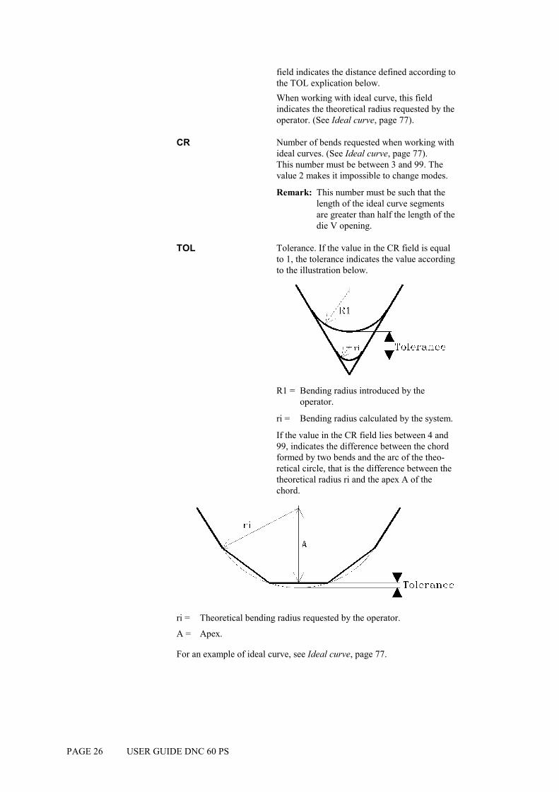
TOL Tolerance. If the value in the CR field is equal to 1, the tolerance indicates the value according to the illustration below.
R1 = Bending radius introduced by the operator.
ri = Bending radius calculated by the system.
If the value in the CR field lies between 4 and 99, indicates the difference between the chord formed by two bends and the arc of the theo-retical circle, that is the difference between the theoretical radius ri and the apex A of the chord.
ri = Theoretical bending radius requested by the operator.
A = Apex.
For an example of ideal curve, see Ideal curve, page 77.

PROGRAMMING PAGE 27
L-ALPHA METHOD
1. If you have it not already on screen, call the PRODUCT L-alpha
page. The screen displays the data concerning the product in the work memory at present.
2. In order to program a new product, the work memory must be cleared by deleting the product already there. If you do not wish to loose that product, you can transfer it to the internal memory by following the instructions below; if the current product is not important or has already been saved, you can pass directly to point 4.
3. To save the product:
! Place the cursor on the P field.
( and to position the cursor on the top of the page.)
! Type the number which you wish to give to this product.
! Press (if the system replies EXISTS, choose another number for saving this product).
The product will be saved in the internal fixed memory with the number which you have given it. It will, however, remain present in the work memory.
4. Delete the product from the work memory:
! Place the cursor on the N field.
! Introduce the value 99.
! Press the key.
The work memory is now empty.
Note that this operation only acts on the work memory and don't destroy the data contained in the internal memory.
PAGE 28 USER GUIDE DNC 60 PS
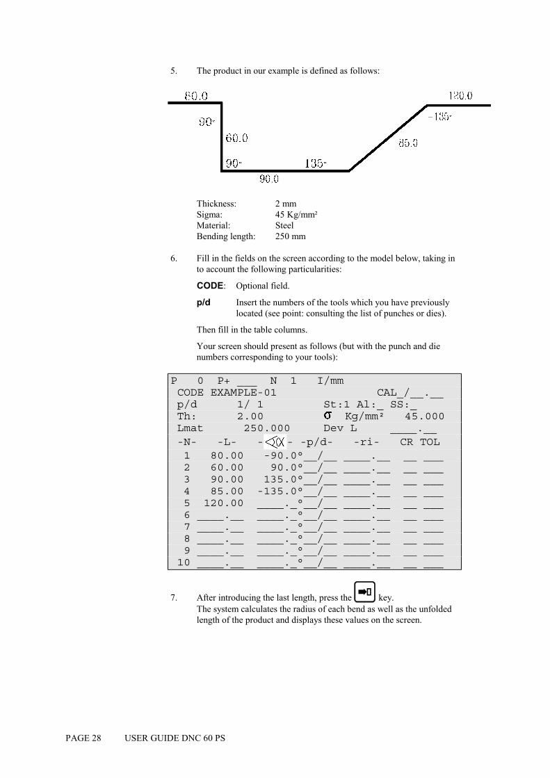
5. The product in our example is defined as follows:
Thickness: 2 mm Sigma: 45 Kg/mm² Material: Steel Bending length: 250 mm
6. Fill in the fields on the screen according to the model below, taking in to account the following particularities:
CODE: Optional field.
p/d Insert the numbers of the tools which you have previously located (see point: consulting the list of punches or dies).
Then fill in the table columns.
Your screen should present as follows (but with the punch and die numbers corresponding to your tools):
P 0 P+ ___ N 1 I/mm CODE EXAMPLE-01 CAL_/__.__ p/d 1/ 1 St:1 Al:_ SS:_ Th: 2.00 Kg/mm² 45.000 Lmat 250.000 Dev L ____.__ -N- -L- - - -p/d- -ri- CR TOL 1 80.00 -90.0°__/__ ____.__ __ ___ 2 60.00 90.0°__/__ ____.__ __ ___ 3 90.00 135.0°__/__ ____.__ __ ___ 4 85.00 -135.0°__/__ ____.__ __ ___ 5 120.00 ____._°__/__ ____.__ __ ___ 6 ____.__ ____._°__/__ ____.__ __ ___ 7 ____.__ ____._°__/__ ____.__ __ ___ 8 ____.__ ____._°__/__ ____.__ __ ___ 9 ____.__ ____._°__/__ ____.__ __ ___ 10 ____.__ ____._°__/__ ____.__ __ ___
7. After introducing the last length, press the key. The system calculates the radius of each bend as well as the unfolded length of the product and displays these values on the screen.

PROGRAMMING PAGE 29
Save this product in the internal memory by proceeding as follows:
! Introduce the number you wish to give the product in the P field, in this case the number 1 for this product which will be used later as an example.
! Press the key. If the system replies with the message EXISTS, choose another number.
Pass on page 30.
MODIFICATION OF A PRODUCT
If you wish to modify a product programmed in L-alpha, call the product from the PRODUCT L-alpha page.
Delete a bend
! Place the cursor on the N field and enter the number of the face to be deleted. :
! Press the key; the face containing the bend is deleted.
Add a bend
! Place the cursor on the N field and enter the number of the face in front of which you wish to insert a new face. :
! Press .The system inserts a line and copies the data of the current bend. Modify the LENGTH and ANGLE fields.
! Start the calculation by pressing .
! Continue in the next chapter. The definition of the bending order has to be reprogrammed.

PAGE 30 USER GUIDE DNC 60 PS
DEFINITION OF THE BENDING ORDER
Press the key, to display the bending order page (Choice 9, PRODUCT BENDS, STOPS of the main menu).
P 1 N 1 p/d 1/ 1 N FACE LEG CR p/d 1 __ __ __ __/__ 2 __ __ __ __/__ 3 __ __ __ __/__ . . . 14 __ __ __ __/__
Explication of the table columns
N Number of the sequence.
FACE Face number.
LEG Number of the face which will press against the stop.
The orientation of the legs is made as a function of the bending order.
CR Number of bends requested when working with ideal curve.
p/d Definition of a tooling pair for a particular bend (if different from the pair specified in the p/d field at the top of the page).
PROGRAMMING PAGE 31
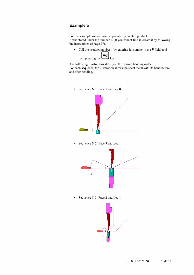
Example a
For this example we will use the previously created product. It was stored under the number 1. (If you cannot find it, create it by following the instructions of page 27).
! Call the product number 1 by entering its number in the P field, and
then pressing the key.
The following illustrations show you the desired bending order. For each sequence, the illustration shows the sheet metal with its bend before and after bending.
! Sequence N 1: Face 1 and Leg 0
! Sequence N 2: Face 3 and Leg 1
! Sequence N 3: Face 2 and Leg 1
PAGE 32 USER GUIDE DNC 60 PS
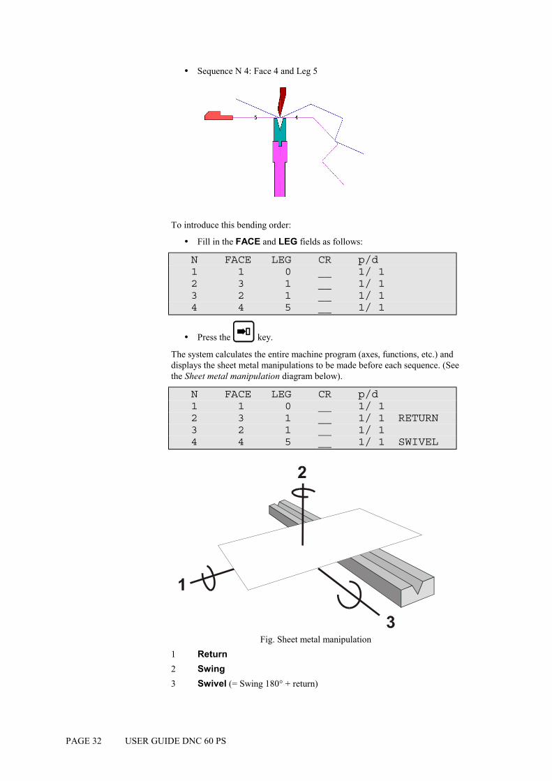
! Sequence N 4: Face 4 and Leg 5
To introduce this bending order:
! Fill in the FACE and LEG fields as follows:
N FACE LEG CR p/d 1 1 0 __ 1/ 1 2 3 1 __ 1/ 1 3 2 1 __ 1/ 1 4 4 5 __ 1/ 1
! Press the key.
The system calculates the entire machine program (axes, functions, etc.) and displays the sheet metal manipulations to be made before each sequence. (See the Sheet metal manipulation diagram below).
N FACE LEG CR p/d 1 1 0 __ 1/ 1 2 3 1 __ 1/ 1 RETURN 3 2 1 __ 1/ 1 4 4 5 __ 1/ 1 SWIVEL
Fig. Sheet metal manipulation
1 Return 2 Swing 3 Swivel (= Swing 180° + return)

PROGRAMMING PAGE 33
! By pressing the key, you can consult the PRODUCT; X; ; Y page which displays for each sequence the X and Y axes' values (the values depend on the used material and tools).
P 1 N 1
N -X- - - -Y- CY 1 78.06 90.0° 229.90 __ 2 145.51 135.0° 233.58 __ RETURN 3 58.06 90.0° 229.90 __ 4 119.39 135.0° 233.58 __ SWIVEL 5 _____.__ ___._° ___.__ 0 6 _____.__ ___._° ___.__ __ 7 …………
Example b
Here is an other bending order.
For this new bending order, the following illustrations show each sequence before and after bending.
! Sequence N1: Face 4 and Leg 0
! Sequence N2: Face 1 and Leg 0

PAGE 34 USER GUIDE DNC 60 PS
! Sequence N 3: Face 2 and Leg 1
! Sequence N 4: Face 3 and Leg 2
! Call the bending order page by pressing the key twice.
! Fill in the FACE and LEG fields as below. You will remark that the p/d fields are already programmed since we have already made a calculation before.
N FACE LEG CR p/d 1 4 0 __ 1/ 1 2 1 0 __ 1/ 1 3 2 1 __ 1/ 1 4 3 2 __ 1/ 1
! Press the key.
The system calculates the entire machine program (axes, functions, etc.) and displays the sheet metal manipulations to be made before each sequence.
N FACE LEG CR p/d 1 4 0 __ 1/ 1 2 1 0 __ 1/ 1 3 2 1 __ 1/ 1 RETURN 4 3 2 __ 1/ 1
PROGRAMMING PAGE 35
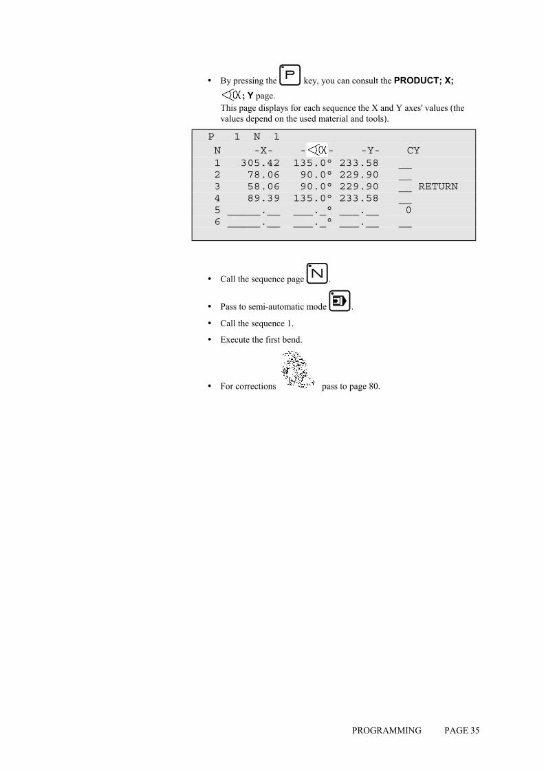
! By pressing the key, you can consult the PRODUCT; X; ; Y page.
This page displays for each sequence the X and Y axes' values (the values depend on the used material and tools).
P 1 N 1 N -X- - - -Y- CY 1 305.42 135.0° 233.58 __ 2 78.06 90.0° 229.90 __ 3 58.06 90.0° 229.90 __ RETURN 4 89.39 135.0° 233.58 __ 5 _____.__ ___._° ___.__ 0 6 _____.__ ___._° ___.__ __
! Call the sequence page .
! Pass to semi-automatic mode .
! Call the sequence 1.
! Execute the first bend.
! For corrections pass to page 80.

PAGE 36 USER GUIDE DNC 60 PS
This page has been left blank intentionally.
PROGRAMMING PAGE 37
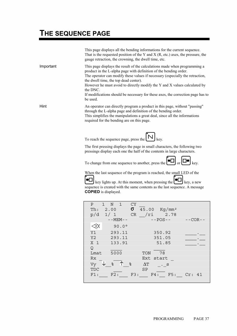
THE SEQUENCE PAGE
This page displays all the bending informations for the current sequence. That is the requested position of the Y and X (R, etc.) axes, the pressure, the gauge retraction, the crowning, the dwell time, etc.
Important This page displays the result of the calculations made when programming a product in the L-alpha page with definition of the bending order. The operator can modify these values if necessary (especially the retraction, the dwell time, the top dead center). However he must avoid to directly modify the Y and X values calculated by the DNC. If modifications should be necessary for these axes, the correction page has to be used.
Hint An operator can directly program a product in this page, without "passing" through the L-alpha page and definition of the bending order. This simplifies the manipulations a great deal, since all the informations required for the bending are on this page.
To reach the sequence page, press the key.
The first pressing displays the page in small characters, the following two pressings display each one the half of the contents in large characters.
To change from one sequence to another, press the or key.
When the last sequence of the program is reached, the small LED of the
key lights up. At this moment, when pressing the key, a new sequence is created with the same contents as the last sequence. A message COPIED is displayed.
P 1 N 1 CY __ Th: 2.00 45.00 Kg/mm² p/d 1/ 1 CR __/ri 2.78 --MEM-- --POS-- --COR--
90.0° Y1 293.11 350.92 ____.__ Y2 293.11 351.05 ____.__ X 1 133.91 51.85 ____.__ Q ____ ____ Lmat 5000 TON 78 Rx _ ___ Ext start _ Vy __% __% ∆T _._s TDC ___ SP ___ F1:___ F2:___ F3:___ F4:__ F5:__ Cr: 41
PAGE 38 USER GUIDE DNC 60 PS
EXPLICATION OF THE FIELDS
P Number of the product in the work memory.
N Bending order (sequence) number to be made.
CY Number of sequence repetitions. (programmed 0, the sequence is jumped)
Th Material thickness.
Tensile strength.
p/d Number of the punch/die pair associated with the bend to be made.
CR/ri Number of bends requested when working with ideal curve (min. 4), and internal bending radius.
--MEM-- This column contains either the values calculated by the system when simulating, or the values programmed by the operator.
--POS-- This column indicates the real axes' positions.
--COR-- This column contains all the sequence and product corrections introduced on the CORRECTION page.
The , Y1, Y2, etc. fields are dependant on the axes programmed in the numerical control.
Q Number of product sequence repetitions. Quantity of products to be produced.
Lmat Bending length.
TON Bending force.
Rx Back gauge retraction. The operator indicates in mm the retraction distance. If nothing is programmed, the beam doesn't stop at the CP. No retraction. If value 0 is introduced, the beam stops at the CP, then executes immediately the bend without carrying out a retraction.
The field between the Rx and the retraction value serves to define the retraction mode. _ = the beam stops at the CP and waits till the
retraction is made, in order to carry out the bend.
1 = the beam stops at the CP, then continues immediately, at the same time as the retraction is carrying out.

PROGRAMMING PAGE 39
Ext start If nothing is programmed in this field, the axes start automatically from the BDC, from the CP or from the TDC, depending on the choice made in the machine parameters.
If 1 is programmed, the start will be made as a function of the configuration made by the constructor. - In most of the configurations, it will be
sufficient to give a down command. At this command, the axes take position, then a second down command has to be given, in order to move the beam.
- In other configurations, the provided start button must be pressed.
- When the message TOL ZONE appears, that means that a down command has been given and that the axes are not positionned in the current sequence. Give a start with the provided button or on the front panel of the DNC.
Vy Beam bending speed. Programmed at 0, the speed is 1 mm/s. Programmed at 9, the speed is 10 mm/s. (If the machine is capable of reaching this speed)
Vy Rising speed from BDC to CP. Programmable from 0 (slow) to 9 (fast). Allows to vary the speed at which the beam rises to the CP. (Function depending on the machine's hydraulics).
∆∆∆∆T Dwell time.
TDC Distance from top dead center.
SP Distance from the beam speed changing point. (Switch Point).
F1: - F5:, Cr Value of the auxiliary functions F1 to F5 and crowning.
These fields can also be re-programmed by the user. However, certain fields are related, that is modifying one provokes a modification of the other.
PAGE 40 USER GUIDE DNC 60 PS
PROGRAMMING ON THE SEQUENCE PAGE
As mentioned at the beginning of this chapter, this page is automatically programmed if the product has been introduced according to the L-alpha method.
Faster It is possible to program a product in this page without going through the L-alpha programming nor the definition of the bending order. The direct programming is the fastest method for an experienced operator, for the whole programming of the product is made on the same page. It enables to program directly the axes' positions and it calculates the bending depth as a function of the introduced angle.
DIRECT PROGRAMMING
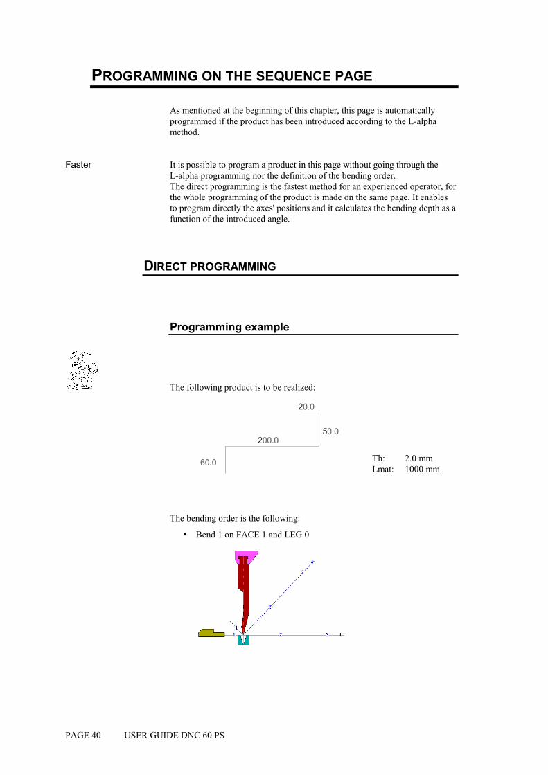
Programming example
The following product is to be realized:
Th: 2.0 mm Lmat: 1000 mm
The bending order is the following:
! Bend 1 on FACE 1 and LEG 0
PROGRAMMING PAGE 41
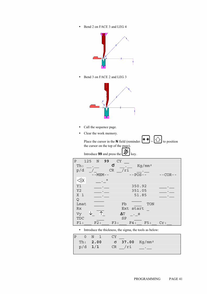
! Bend 2 on FACE 3 and LEG 4
! Bend 3 on FACE 2 and LEG 3
! Call the sequence page.
! Clear the work memory.
Place the cursor in the N field (reminder: + to position the cursor on the top of the page).
Introduce 99 and press the key.
P 125 N 99 CY __ Th: __.__ __.__ Kg/mm² p/d _/_ CR __/ri __.__ --MEM-- --POS-- --COR--
__._° Y1 ___.__ 350.92 ___.__ Y2 ___.__ 351.05 ___.__ X 1 ___.__ 51.85 ___.__ Q ____ ____ Lmat ____ Fb ___ TON Rx ___ Ext start _ Vy _ _ ∆∆∆∆T _._s TDC ___ SP ___ F1:___ F2:___ F3:___ F4:__ F5:__ Cr:__
! Introduce the thickness, the sigma, the tools as below:
P 0 N 1 CY __ Th: 2.00 σ 37.00 Kg/mm² p/d 1/1 CR __/ri __.__

PAGE 42 USER GUIDE DNC 60 PS
! Program 90 in the field, by leaving the field, the system calculates the Y1 and Y2 axes' values.
! Introduce 58.0 in the X field (stop position for this first bend).
! Introduce the bending length 1000. The system calculates the pressure and the crowning automatically.
! If necessary, introduce the dwell time (by default non-programmed = 0.5 s), the gauge retraction, the bending speed reduction, the slow raising, etc.
! Press the sequence forwards key , in order to copy this first sequence in sequence 2. The message COPIED is displayed, the N field passes on 2. The LED of the key remains lighted, indicating that you are on the last sequence.
2nd sequence The following screen is displayed:
Remark: the values Y1, Y2, Fb and Cr will vary, for they are calculated as a function of the programmed tools. The values POS Y1, Y2 and X will also be different, for they display the real position of the axes.
P 0 N 2 CY __ Th: 2.00 37.00 Kg/mm² p/d 1/ 1 CR __/ri __.__ --MEM-- --POS-- --COR-- 90.0° Y1 229.90 350.92 ____.__ Y2 229.90 351.05 ____.__ X 58.00 51.85 ____.__ Q ____ ____ Lmat 1000 TON 19 Rx ___ Ext start _ Vy _ _ ∆∆∆∆T _._s TDC ___ SP ___ F1:___ F2:___ F3:___ F4:__ F5:__ Cr: 41

PROGRAMMING PAGE 43
Modify the values which are different for this sequence, in this case enter 18 in the X field.
P 0 N 2 CY __ Th: 2.00 37.00 Kg/mm² p/d 1/ 1 CR __/ri __.__ --MEM-- --POS-- --COR-- 90.0° Y1 229.90 350.92 ____.__ Y2 229.90 351.05 ____.__ X 18.00 51.85 ____.__ Q ____ ____ Lmat 1000 TON 19 Rx ___ Ext start _ Vy _ _ ∆∆∆∆T _._s TDC ___ SP ___ F1:___ F2:___ F3:___ F4:__ F5:__ Cr: 41
! Press the sequence forwards key , in order to copy this second sequence in sequence 3. The message COPIED is displayed, the N field passes on 3. The LED of the key remains lighted, indicating that you are on the last sequence.
3rd sequence The following screen is displayed:
P 0 N 3 CY __ Th: 2.00 37.00 Kg/mm² p/d 1/ 1 CR __/ri __.__ --MEM-- --POS-- --COR-- 90.0° Y1 229.90 350.92 ____.__ Y2 229.90 351.05 ____.__ X 1 18.00 51.85 ____.__ Q ____ ____ Lmat 1000 TON 19 Rx ___ Ext start _ Vy _ _ ∆∆∆∆T _._s TDC ___ SP ___ F1:___ F2:___ F3:___ F4:__ F5:__ Cr: 41
! Modify the values which are different for this sequence, in this case enter the value 48 in the X field.
The programming of the product is terminated.
PAGE 44 USER GUIDE DNC 60 PS
If you wish to save:
! Place the cursor on the P field.
( and to position the cursor on the top of the page.)
! Introduce the number you wish to give to this product.
! Press (if the system replies EXISTS, choose another number for saving this product).
The product will be saved in the internal memory with the number which you have given it. It will, however, remain present in the work memory.
! Pass to semi-automatic mode .
! Call the sequence 1.
! Execute the first bend.
! For corrections pass to page 80.
PRODUCT MANAGEMENT PAGE 45
PRODUCT MANAGEMENT
This chapter indicates how to manage the products (programs) stored in the numerical control.
LIST OF PRODUCTS
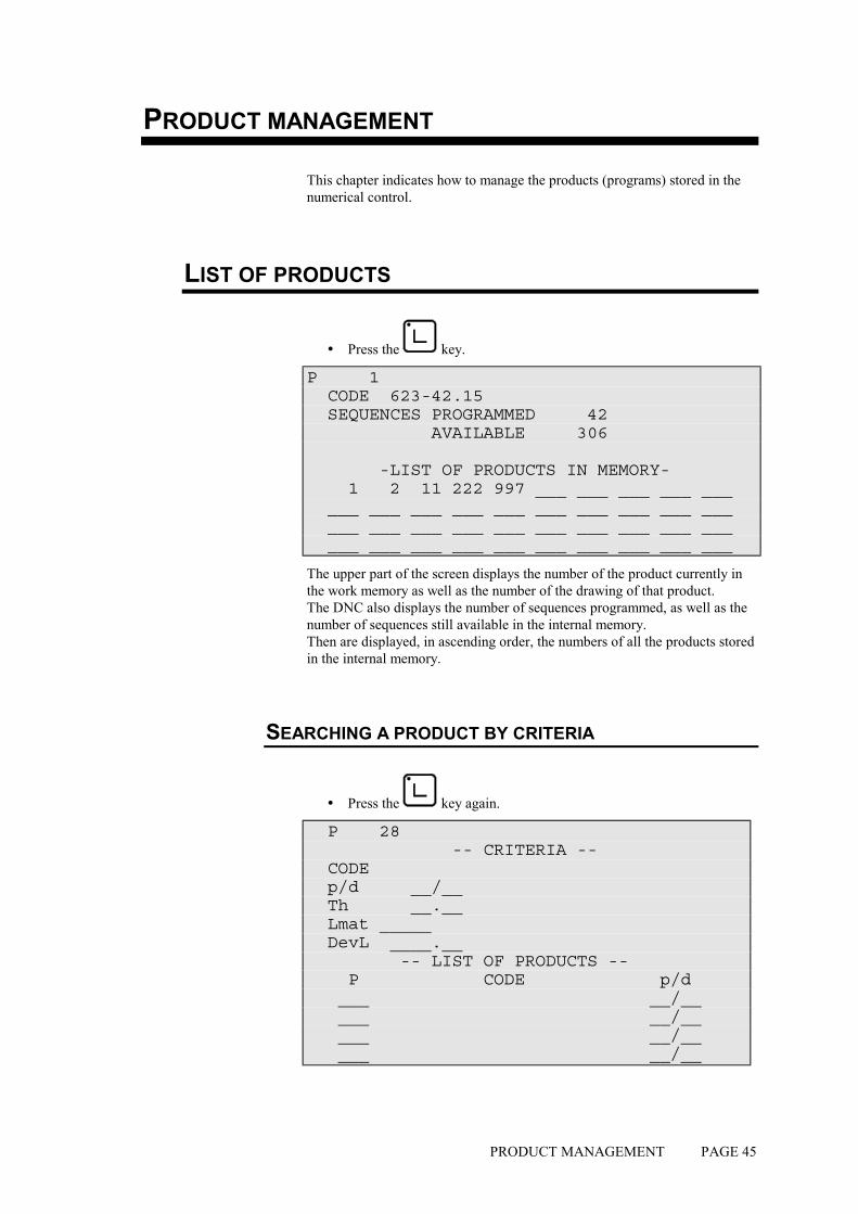
! Press the key.
P 1 CODE 623-42.15 SEQUENCES PROGRAMMED 42 AVAILABLE 306 -LIST OF PRODUCTS IN MEMORY- 1 2 11 222 997 ___ ___ ___ ___ ___ ___ ___ ___ ___ ___ ___ ___ ___ ___ ___ ___ ___ ___ ___ ___ ___ ___ ___ ___ ___ ___ ___ ___ ___ ___ ___ ___ ___ ___ ___
The upper part of the screen displays the number of the product currently in the work memory as well as the number of the drawing of that product. The DNC also displays the number of sequences programmed, as well as the number of sequences still available in the internal memory. Then are displayed, in ascending order, the numbers of all the products stored in the internal memory.
SEARCHING A PRODUCT BY CRITERIA
! Press the key again.
P 28 -- CRITERIA -- CODE p/d __/__ Th __.__ Lmat _____ DevL ____.__ -- LIST OF PRODUCTS -- P CODE p/d ___ __/__ ___ __/__ ___ __/__ ___ __/__

PAGE 46 USER GUIDE DNC 60 PS
This page allows to display a list of searched products according to one or more criteria like the code number, the thickness, the bending length and/or the unfolded length.
Under the heading --CRITERIA-- are displayed the different criteria according to which it is possible to search for a product. These criteria can be combined, that is it is possible, for example, to ask for the list of all the products stored using a specific tool pair and having a particular material thickness.
The products meeting the defined selection criteria are displayed on the second half of the screen.
To make a search by criteria, proceed as follows:
! Introduce one or more selection criteria in the fields provided.
! Press .
If the list contains 7 or more products, the following page or pages can be
displayed by pressing .
CALLING A PRODUCT
This operation searchs a product in the internal memory and place it into the work memory.
Calling a product is possible from all pages on which the cursor can be placed on the P or CODE field.
Attention: The called product "erases" the product already in the work memory. Pay attention to save, if necessary, the current product before calling another product.
! Introduce the product number in the P field or the code number in the CODE field.
! Leave the cursor on the field which has been programmed just now.
! Press . The product requested is then copied into the work memory (the original of this product is, of course, conserved in the internal memory).
SAVING A PRODUCT
This operation is used to permanently save a product located in the work memory.
Saving a product is possible from all pages on which the cursor can be placed on the P field.
It should be noted that after saving the product remains present in the work memory.
To save a product proceed as follows:

PRODUCT MANAGEMENT PAGE 47
! If you wish to give a drawing number or name to the product, fill in the CODE field. This operation is optional.
! Enter the number of the product in the P field.
! Leave the cursor in the P field.
! Press the key. If the system displays the message EXISTS, choose another number.
If you wish to save a product under a number which already exists (e.g. after modifying a product), the product bearing that number must first be deleted in the internal memory.
NB: Attention, the N° 998 and 999 are reserved for special functions.
! 998 for the temporary storage of the work memory contents during PC <-> DNC transfer.
! 999 for total deletion of the internal memory (see page 47).
DELETING A PRODUCT
! Call the list of products page.
! Place the cursor on the P field and introduce the number of the product to be deleted.
! Press .
It should be noted that this action has no effect on the internal memory.
DELETING ALL THE PRODUCTS
Attention This operation deletes the totality of the products stored in the internal memory without the possibility to cancel this command.
! Call the list of products page.
! Introduce the value 999 in the P field.
! Press .

PAGE 48 USER GUIDE DNC 60 PS
This page has been left blank intentionally.

TOOL PROGRAMMING PAGE 49
TOOL PROGRAMMING
The DNC 60 has several pages which allow consultation of the list of existing tools, to display them and / or program new ones.
The DNC 60 memory can hold a maximum of 20 punches and 30 dies.
LIST OF PUNCHES
! From the main menu choose option LIST OF PUNCHES. The system displays the list of punches existing in the memory, with the number and characteristics of each punch:
LIST p/d 1/ 1 p/d 1/__ __/__ __/__ __/__ PUNCH p 90° ___° ___° ___° hp 100.00 ___.__ ___.__ ___.__ rp 1.50 ___.__ ___.__ ___.__ TON/M 100 ___ ___ ___ DIE Vd ___.__ ___.__ ___.__ ___.__ d ___° ___° ___° ___° hd ___.__ ___.__ ___.__ ___.__ rd ___.__ ___.__ ___.__ ___.__ TON/M ___ ___ ___ ___ REF Y ___.__ ___.__ ___.__ ___.__ SAF X ___.__ ___.__ ___.__ ___.__
If your DNC contains more than 4 punches, you can call the following page
or pages by pressing .
List of dies
From the main menu, choose option LIST OF DIES.
The consultation of the list of dies can be done in the same way as explained for the punches.
PAGE 50 USER GUIDE DNC 60 PS
PUNCH / DIE PROGRAMMING
GENERAL EXPLICATIONS
The programming of tools is done by introducing their values and dimensions on the page as represented below.
! Call the PROGRAMMING PUNCH / DIE page (via the main menu).
p Punch angle.
hp Height of the punch between the lowest part of the beam and the point of the punch.
rp Punch radius.
TON/M Maximum force supported by the punch per linear meter.
Vd V width of the die.
d V angle of the die.
hd Height of the die from the surface of the table.
rd Die radius.
TON/M Maximum force supported by the die per linear meter.
REF Y Sum of the hp and hd. This value is automatically calculated during programming of pairs. See Erreur ! Résultat incorrect pour une table..
SAF X X Safety distance. (Not programmed = half V opening)
a: and b: Table and die dimensions according to the drawing displayed on the screen.
TOOL PROGRAMMING PAGE 51
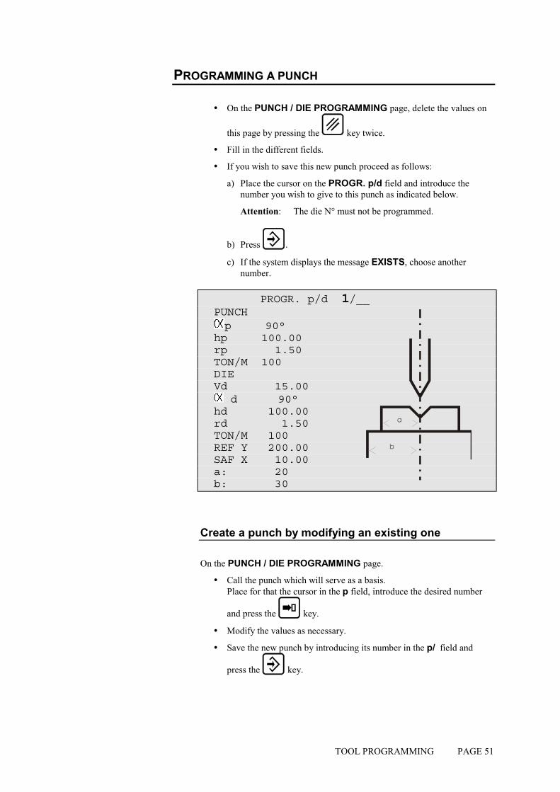
PROGRAMMING A PUNCH
! On the PUNCH / DIE PROGRAMMING page, delete the values on
this page by pressing the key twice.
! Fill in the different fields.
! If you wish to save this new punch proceed as follows:
a) Place the cursor on the PROGR. p/d field and introduce the number you wish to give to this punch as indicated below.
Attention: The die N° must not be programmed.
b) Press .
c) If the system displays the message EXISTS, choose another number.
PROGR. p/d 1/__ PUNCH p 90° hp 100.00 rp 1.50 TON/M 100 DIE Vd 15.00 d 90° hd 100.00 rd 1.50 TON/M 100 REF Y 200.00 SAF X 10.00 a: 20 b: 30
Create a punch by modifying an existing one
On the PUNCH / DIE PROGRAMMING page.
! Call the punch which will serve as a basis. Place for that the cursor in the p field, introduce the desired number
and press the key.
! Modify the values as necessary.
! Save the new punch by introducing its number in the p/ field and
press the key.

PAGE 52 USER GUIDE DNC 60 PS
MODIFY AN EXISTING PUNCH
On the PUNCH / DIE PROGRAMMING page.
! Call the punch which will serve as a basis. Place for that the cursor in the p field, introduce the desired number
and press the key.
! Modify the values as necessary.
! To be able to save this punch under the same number, the former version must first be deleted from the internal memory.
Place the cursor on the punch number and press the key.
! Leave the cursor at the same place and press .
Attention: The die N° must not be programmed.
The former version of your punch has now been replaced by the new one which has the same number.
DELETE A PUNCH
! Call the LIST OF PUNCHES page (via the main menu).
! Introduce the number of the punch to be deleted in the p/ field.
! Press .
PROGRAMMING A DIE
The programming of a die is done in the same way as for a punch, but in the /m field.

TRANSFER PAGE 53
TRANSFER
For transfer to a PC by serial line the DNC 60 must be equipped with the RS232 option. .
Products The PC must be equipped with the CYBELEC PC900 / PC1200 software with option LINK7000. This unity allows to create products in the bending software on PC and to transfer them to the DNC for execution.
Backup The PC must be equipped with the CYBACK storage software. CYBACK allows to make a backup of the data in the DNC without intervention on the data on the PC's level.
Updating Easy, practical and very rapid, this possibility facilitates in case of necessity the updating of the DNC software in the FLASH memory. The PC must be equipped with the updating software.
! Call the TRANSFER DNC <--> PC page via the main menu.
DNC <-> PC STATUS TRANSFER _ 1 DNC --> PC 2 PC --> DNC 3,4 DATA LINK TEST 1 2 7 FLASH 8 EXT KEYBD 9 MODEM CHOICE _ 1 PRODUCTS 2 TOOLS 4 PARAMETERS 6 PRODUCTS N° __ ( ) __ ( ) __ ( )
Who commands ? This page will only be used to initialize the transmission type. It is not possible to start the transmission from the DNC, this will always be done from the PC.
TRANSFER Allows to select the type of transmission.
DNC #### PC Initializes the transmission PC-DNC. Mode 1 or 2 can be selected indifferently.
DATA LINK TEST Selects the test mode of the serial ports. See the following chapter.
FLASH Prepares the DNC to receive an updating.
EXT KEYBD Puts the DNC in external terminal mode. See the concerned chapter.
MODEM Not yet available.
CHOICE This field allows to select the objects to be transferred. In the case of option 6 PRODUCTS N°, it is necessary to fill in the last fields of the page with the numbers of the products to be transferred.

PAGE 54 USER GUIDE DNC 60 PS
TESTS OF THE SERIAL PORTS
The 2 serial ports of the DNC 60 are SUB-D 9P, plugs J5 and J6.
! Introduce and verify that the transmission parameters are programmed as follows:
PARAMETERS RS232 / DIVERS . . . -- COMPUTER LINK –- 106 BAUD RATE 4800 STOP 1.0 PARITY ODD(1) EVEN(2) _ BITS 8 PROTOCOLE _ BCC ___
! Set a test loopback connector on the serial line connector RS232 to be tested.
! Press the key to start the test. The message RUN must flash.
! To stop the test, press the (STOP) key.
If you wish as well to test the cable:
! Connect the transmission cable to the DNC and fit a short circuiting loopback connector on the other end of the cable to be tested.
Test loopback connector
Pin 2 (RXD) wired to pin 3 (TXD) Pin 4 (DTR) wired to pin 6 (DSR) Pin 7 (RTS) wired to pin 8 (CTS)
RS 232 transmission cable
The shield must be connected on the metallic hood of the Sub-D plugs.
TRANSFER PAGE 55
LINK 7000 / CYBACK
For these two programs the RS cable must be connected on the RS232 port of the J5 plug. The transmission parameters must be programmed on the DNC with the same values as for the test of the serial ports (see paragraph above). These same values must be programmed on the PC.
If the transmission runs at 4800 baud, you can try to increase the transmission speed at 9600 baud. The RS 232 norm gives as limit 15m. By using a more important distance, there is a risk of bad transmission and it will be necessary to diminue the transmission speed.
Reminder: The transmission command can be given only from the PC side.
To permit the serial transmission with CYBACK:
Pass to programming mode.
! Call the TRANFER DNC <�> PC page.
! Introduce 2 in the TRANSFER field.
! Press the key. The display indicates STATUS RS232.
Programming mode From this instant on, the DNC can receive data sent from the PC, provided that the DNC is in programming mode. In the other modes (auto, semi-auto or manual) the DNC doesn't respond, the transmission is not accepted. During the transmission the operator can leave the DNC on any page. It is not necessary to display the transfer page.
The transfer mode remains memorized, even if the DNC is disconnected from power supply. It has to be re-programmed if the mode has been changed (for instance FLASH).
PC900/1200 and LINK7000
Use the conversion file SIXFAFIØ.XFR and followings.

PAGE 56 USER GUIDE DNC 60 PS
This page has been left blank intentionally.

WORKING MODES PAGE 57
THE MACHINE WORKING MODES
3 working modes are generally available at machine level. The functioning is described hereinafter.
Depending on the manufacturers and the safety standards in force in the country, the functioning can be different.
Adjustment mode
Sensitive mode
Automatic mode
These modes are independent of the DNC modes and can be combined. Exception: the adjustment mode.
ADJUSTMENT MODE
This mode only functions with the DNC in mode.
If this is not the case, the press refuses to descend.
In this mode the table only functions in bending speed with the pressure and speed programmed in the current sequence.
The top dead center of the current sequence is active, it is thus not possible to raise the beam above this point.
On the other hand, the bottom dead center programmed in the sequence is not active. Thus only stopping the descent command, or a mechanical stop (punch in the die), or the lower limit switch will stop the beam in the descent phase.

PAGE 58 USER GUIDE DNC 60 PS
SENSITIVE MODE
DNC in mode
The functioning is identical to adjustment mode, except that the return to the TDC is made in one movement.
DNC in or mode
The press works in the conventional way, that is:
! High speed approach
! Deceleration
! Safety stop (if the mode requires it)
! Bending
! Bottom dead center
It is at the bottom dead center (BDC) that the differences appear.
The DNC remains under pressure at the bottom dead center until the descent command disappears, and this indifferently to the dwell time at BDC.
When the descent command is suppressed, the DNC remains at the BDC without pressure or descent command, until reception of a rise command which it executes immediately.
AUTOMATIC MODE
This mode functions in a similar way to sensitive mode, except that the raising of the beam is made automatically once the dwell time programmed in the current sequence has elapsed.
This even if the descent command remains active.
NB: In all these modes the ascent command has priority. It is executed immediately on its reception.

PROTECTION OF ACCESS LEVELS PAGE 59
PROTECTION OF THE ACCESS LEVELS
GENERAL INFORMATION
Depending on the version, the DNC 60 can or can not be equipped with a 4-positions physical key. However the protection levels 0-1-2 and 3 still exist. For the case where the physical key doesn't exist, the access is made by password.
ATTENTION : these passwords will be reset in the default values at each initialization of the machine parameters (817 on INIT page and Choice Init Mach Par = 1).
Thus, in this manual we always will speak of a (virtual) key position like e.g.: "Key in position 3".
Levels There exist 4 access levels, 0 to 3.
0 = Programming prohibited.
1 = Creation, correction, modification, saving, deleting, transfer of one (or more) product(s).
2 = Creation, correction, modification, saving, deleting, transfer of the tools.
3 = Programming, modification and transfer of the machine parameters.
Access These levels are accessed by pressing the
+ or keys. (Release the 0-3 key before the stop key). The key position is displayed as a number on the upper right part of the screen (after the interactive field).
When passing to a higher, not authorized level, a password modification will be requested. When the password has been introduced, you can "navigate" levels inferior or equal to the authorized one without reintroducing the password. Passing to level 0 resets password validity.
Users A number of different users are predefined. A user is not a physical person in particular, but can be e.g. all the operators having the authorization to work on the machine. Each predefined user possesses his own password and a maximum level which he can reach. See further under Table of users, access and passwords.
Password Certain users can modify their own password. For the others, the password can only be changed by a user having a superior access.
Loss of the password In case of loss of the password, a user of a superior level has to reprogram the password.

PAGE 60 USER GUIDE DNC 60 PS
THE USERS
Table of users, access and passwords
Level Names of predefined users
Changing of the personal
password
Changing of passwords of
the subordinateds
Level virtual key
Password by default
User generally attributed to:
1 EUL1 NO NO 1 111 Operators having the access authorization of level 1
2 EUL2 NO NO 2 222 Operators having the access authorization of level 2
3 EUL3 NO NO 3 333 Operators having the access authorization of level 3
4 WSSUPER OK OK 3 817 Workshop supervisor
5 MACHMAN NO OK 3 Machine manufacturer's Service technicians
6 MACHMAN0 OK OK 3 Responsible of the technicians at the machine manufacturer's
A predefined user is just a role. Many physical persons can have the same role. E.g., many physical operators can be a EUL1 (level 1).
After installing the machine it is advised to modify the password by default of level 4 (WSSUPER = Workshop supervisor) and of level 3 (EUL3 = Operators with authorization level 3), because the passwords are in this manual.

PROTECTION OF ACCESS LEVELS PAGE 61
ACCESS BY PASSWORD
By starting the software, the virtual key is always positioned at 0.
! Choose the level to access by pressing one of the combinations
+ , or .
! The message VALUE ? appears.
! Introduce the password and press the key to validate the password.
! The message OK and the selected level are displayed if the password is accepted, or KO if it is refused.
Once the authorization acquired, the operator can change the level among those authorized to him without reappearing of a new password request. For instance, a user with access on level 3 can navigate between levels 1, 2 and 3 without having to give his password again.
If level 0 is activated, the access on any other level will require to introduce the password again. This request will also appear when the user passes to a superior level (from 0 to 1, from 1 to 2, from 2 to 3, etc.) and he has no access authorization.
Advice If you have accessed to level 3, access to level 0 after your intervention. This will avoid to make undesired changings by inadvertence.

PAGE 62 USER GUIDE DNC 60 PS
ACCESS TO LEVELS SUPERIOR TO 3
Certain users can access to levels superior to 3, which enables them, among other things, to modify the passwords. In order to know the authorizations, see Table of users, access and passwords.
! Press the keys combination + .
! The message LEVEL ? appears.
! Type the level number you want to log in.
! The message VALUE ? appears.
! Introduce the password corresponding to the requested level and
validate with the key.
! The DNC passes to level 1. The operator can "navigate" between levels 1 and 3 without reintroducing his password. If his access level enables him, he can call the procedure of password modification (see next paragraph).
! At the end of the intervention, don't forget to pass to level 0 in order to leave the current level.
PROTECTION OF ACCESS LEVELS PAGE 63
CHANGE PASSWORD
It is possible to modify the passwords attributed by default.
Certain users can do it for themselves, others not. In order to know the authorizations, see Table of users, access and passwords.
To change a password:
! Press the keys combination + .
! The message LEVEL ? appears.
! Type the level number you want to log in.
! The message VALUE ? appears.
! Introduce the password corresponding to the requested level and
validate with the key.
! Then select the keys combination + .
! The message LEVEL ? appears.
! Program the level on which you want to modify the password. The message IGNORE appears if the requested level is superior to the "logged" level, in the contrary, the message VALUE ? appears.
! Introduce the desired new password and validate with the key.
! The message CONFIRM appears.
! Introduce the new password again and validate with .
! If the 2 registered passwords are identical, the message OK is displayed.
! If the 2 registered passwords are different, the user is invited to introduce the 2 passwords again, the message VALUE is displayed.
! At the end of the intervention, don't forget to pass to level 0 in order to leave the current level.
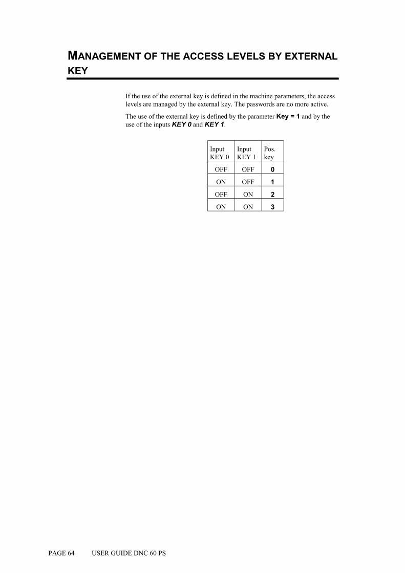
PAGE 64 USER GUIDE DNC 60 PS
MANAGEMENT OF THE ACCESS LEVELS BY EXTERNAL KEY
If the use of the external key is defined in the machine parameters, the access levels are managed by the external key. The passwords are no more active.
The use of the external key is defined by the parameter Key = 1 and by the use of the inputs KEY 0 and KEY 1.
Input KEY 0
Input KEY 1
Pos. key
OFF OFF 0
ON OFF 1
OFF ON 2
ON ON 3

ANNEXES PAGE 65
ANNEXES
THE INITIALIZATION PAGE
This page appears if a calculation is impossible, due to unprogrammed data or an incorrect value.
It can also appear as a result of pollution of one of the memory zones which will also give impossible calculations. INITIALIZATION DNC 60 PS -- MEMORY ZONE -- _ Clear variables zone _ Clear punches-dies zone _ Clear machine parameters zone EXECUTION CODE ___
It can be necessary to display this page intentionally in order to clear completely the data of the DNC and to re-start the programming on a "clean" basis.
To display the initialization page:
Switch on the machine by pressing the and keys.
In case of unexpected apparition of the init page, proceed as follows:
If point n° 1 does not re-establish a normal situation, go on to the next point and so on.
The following operations clear successively all the data in the selected memories.
It is therefore recommended to re-introduce the data.
1) Press the key twice.
2) Enter: value 1 in the field Clear variables zone
and value 817 in the field EXECUTION CODE.
Press the key.
Press the key twice.

PAGE 66 USER GUIDE DNC 60 PS
3) Enter: value 1 in the field Clear variables zone,
value 1 in the field Clear punches-dies zone
and value 817 in the field EXECUTION CODE.
Press the key.
Press the key twice.
4) Enter: value 1 in the field Clear variables zone,
value 1 in the field Clear punches-dies zone,
value 1 in the field Clear machine parameters zone
and value 817 in the field EXECUTION CODE.
Press the key.
Press the key twice.
The clearing of the machine parameters deletes also all the input / output configuration defined by the operator.
It is therefore advisable to re-configure the DNC 60 before the next use.
Attention: If you use an external system for the data re-introducing (LINK 7000, CYBACK via RS232) and the problem persists, then the informations re-entered by this system have to be called into question. The best to do in this case is to delete again the whole contents of the DNC and to re-program the DNC manually via the keyboard (not the RS232 line).

ANNEXES PAGE 67
THE TOOL REFERENCE
The machine has been adjusted according to the following principle:
When, theoretically, the punch's leg face on the beam is in contact with the surface of the table, the value of the Y1 and Y2 counters is 000.00.
In practice this adjustment is made using two calibrated blocks, whose value has been introduced into the counters.
Definition: The reference value (REF Y) is theoretically the sum of the heights of both tools; punch and die.
The height of the punch is the distance between the "point" of the punch and its leg face on the beam.
The precision of all bends realized by the machine depends on the reference value REF Y.
The numerical control calculates the bending depth using:
! the REF Y value,
! the geometrical values of the tools,
! the sheet metal thickness.
If the resulting bends differ greatly from the programmed value, the reference and the values above must be controlled.

PAGE 68 USER GUIDE DNC 60 PS
To control the reference, simply, in mode, place the point of the punch on the flat of the die (be careful with the pressure of the active sequence) and read the value indicated by the POS Y1 and Y2 counters.
This value must be identical, for both counters and also correspond to the REF Y reference value displayed on the PUNCH / DIE PROGRAMMING page.
If it is not possible to move the die to obtain a situation as shown above, it is possible using a die with a small opening, to place on the die a thick sheet (which will not bend under the weight of the beam) or blocks of a known precise thickness, (see figure below).
The value of the material introduced between the punch and the die must then be subtracted to obtain the reference value REF Y.
ANNEXES PAGE 69
Y1 and Y2 counters greatly different
If the counters are not identical and present a difference superior to what is normally tolerated (the press in this case furnishes an angle which varies from one side to the other of the machine), a test must be made with another tool in order to determine if the difference comes from the tool itself (tool badly finished presenting a difference in height along its length) or if the press is badly calibrated. In the latter case, you must contact the manufacturer.
Y1 and Y2 counters identical, but different from REF Y
If the difference between the counters Y1 and Y2 is within the acceptable tolerance, but the Y1-Y2 value is greatly different from the REF Y value, you must determine if the difference comes from the height of the die or that of the punch.
In this case the tool at fault must be corrected so that the REF Y result is identical to the value of the Y1 Y2 counters.
Modification of the reference for the product
The possibility exists to modify the reference for each tool used for the product. This modification is stored with the product.
It is in some ways a reference modification per product tool. It is thus possible in this case for the same tool pair used for two distinct products, to have a reference modified positively in the product XXX and to have a reference modified negatively for the product YYY.
The principle of measure / control is identical to that which is described above.
To modify the reference in a particular product, you must access the PRODUCT PUNCHES / DIES page via the main menu, choice 7, and program the new reference in the REF Y field which is accessible by the cursor.
All the sequences having the same tooling will be modified.

PAGE 70 USER GUIDE DNC 60 PS
THE CONTACT POINT (CP) OR PINCH POINT
Definition:
The contact point is the position of the beam which corresponds to the moment when the point of the punch makes contact with the sheet metal placed in the die.
This point is not programmable, but is calculated by the DNC using the REF Y value and the sheet thickness.
The position is determined by the following calculation:
PCT = REF Y + Th (sheet thickness).
The CP is used by the DNC cycle to maintain the sheet when an X backgauge retraction is programmed.
As we have seen at the beginning of this chapter, the CP is closely linked to the Y reference and the sheet thickness.
The following cases may occur:
a) the sheet is not pinched during X backgauge retraction
b) the sheet is bent too much during X backgauge retraction
To remedy these problems you must:
! verify the sheet thickness and if necessary correct it
! verify the reference and if necessary correct it
! add a CP correction in parameter 37.
A simple way of verifying the position of the CP is to program a sequence with a very large retraction (approx. 400 mm) and make a descent of the beam.
During the execution of the retraction, the beam stops on the sheet, it is thus easy to control if the sheet is pinched sufficiently or too much.
Simply interrupt the descent command before the end of retraction to prevent the beam from bending the sheet. An ascent command frees it immediately for another try.
For the softwares having the "CP correction" parameter, if the reference, the tooling dimensions and material thickness are correct you can modify this parameter in order to correct the CP (adjustment of the material clamping) without interfering with the other points.

ANNEXES PAGE 71
THE GAUGE AXES
The addition of supplementary axes (to X) does not present any difficulties for the operator, the fields being clearly defined on the screen.
The safety factors concerning the supplementary axes such as R, X1, X2, Z1 and Z2 are described below.
X-R safety factors
When the R axis is a digital axis, an anti-collision safety factor prohibits the positioning of the gauge probes in the die.
A safety zone encircling the die provokes a particular type of positioning when the probes position themselves in this zone.
The safety zone encircling the die is defined by the data introduced in the machine parameters, and are defined by the manufacturer.
The zone where all positioning is prohibited, is defined using the values introduced for each set of tools.
1 Safety zone
2 Prohibited zone
3 Value Safety die X parameter 50
4 Value Safety die R parameter 50
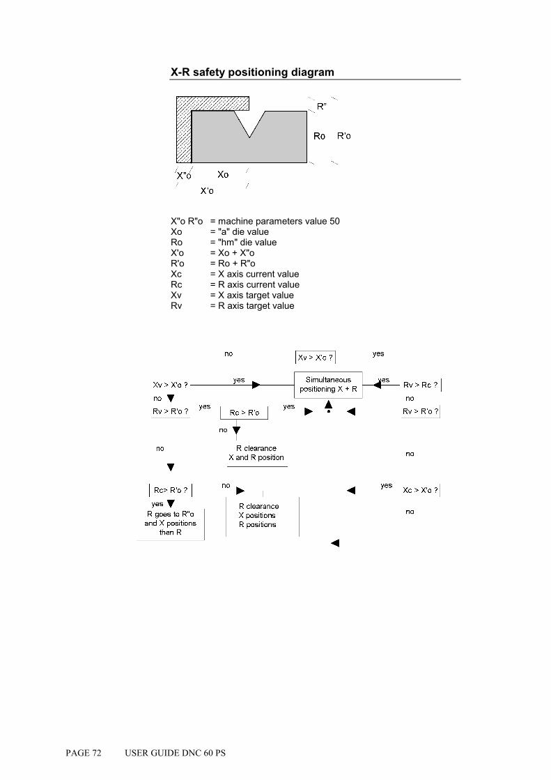
PAGE 72 USER GUIDE DNC 60 PS
X-R safety positioning diagram
X"o R"o = machine parameters value 50 Xo = "a" die value Ro = "hm" die value X'o = Xo + X"o R'o = Ro + R"o Xc = X axis current value Rc = R axis current value Xv = X axis target value Rv = R axis target value

ANNEXES PAGE 73
Two examples of positioning
These two examples show that it is possible to position in the safety zone.
If the positioning requested is situated in the prohibited zone, the DNC
refuses to go into or mode and the cursor moves to the X field.
1 Departing position 2 Temporary stopping position 3 Destination position
Xv > X'c ?
Xv > X'o ?
Rv > R'o ? Rc > R'o Rv > R'o ?
Rv > Rc ?
Xc > X'o ?Rc> R'o ?
dégagement Rpos. X et R
ouinon
oui
oui
ouioui
oui
non
non
non
non
non
non
non
oui Positionnementsimultané X et R
dégagement Rpuis pos. Xpuis pos. R
Pos à R'o et X puis R
1 Departing position 2 Temporary stopping position 3 Temporary stopping position 4 Destination position
Xv > X'c ?
Xv > X'o ?
Rv > R'o ? Rc > R'o Rv > R'o ?
Rv > Rc ?
Xc > X'o ?Rc> R'o ?
dégagement Rpos. X et R
ouinon
oui
oui
ouioui
oui
non
non
non
non
non
non
non
oui Positionnementsimultané X et R
dégagement Rpuis pos. Xpuis pos. R
Pos à R'o et X puis R

PAGE 74 USER GUIDE DNC 60 PS
X1-X2 safety factor
The safety factors offered for X1 X2 are identical to the ordinary X axis.
The nearest axis (X1 or X2) to the die is taken into account for the safety factor.
Z1-Z2 safety factor
An anti-collision safety factor prevents the passage to and modes, and the interactive message "Z1-Z2" is obtained if the positioning is impossible (see parameter 51).
Normally the origin of the Z axes is on the left of the machine when looking at the front of the machine.

ANNEXES PAGE 75
PROGRAMMING THE AXES DATUM
Select option 11 of the main menu, the following page appears:
AXES DATUM --SET-- --POS-- X _____.__ 0.00 Y1 ____.__ ____.__ Y2 ____.__ ____.__
! Introduce in the SET column the values for the axes datum.
! Leave the field for validation. At this moment , the POS field takes the new value.
Dangerous operation
! This operation can only be executed by an experimented operator who knows the consequences of his modification.
! If you modify the position of an axis in this way, make sure that it corresponds to the reality. After modifying, the electronic, electrical and mechanical limit switches are to verify. Generally the axis in question is displaced in manual mode slow speed up to the negative/positive limit switch.
! It is recommended not to modify Y1 and Y2. If this should be the case however, a particular caution has to be taken. In fact, if you modify here the position and an error is committed, the damages caused by this modification can be dangerous and/or harmful for the functioning of the machine. Furthermore this modification get lost at each restarting of the machine.
CALIBRATION
The CAL (calibration) field on the PRODUCT STATUS page is used for the automatic compensation of variations in sheet metal thickness.

PAGE 76 USER GUIDE DNC 60 PS
To ensure the good working of this function, it is necessary that the beam can "set down" on the sheet metal with minimum pressure without bending it.
The principle of functioning is as follows:
The beam approaches the sheet at minimum speed and pressure, the resistance of the sheet will stop the beam. This stop allows to measure the thickness of the sheet under the punch, and in the case of a difference with a reference sheet, to make a correction.
It is thus essential that the sheet is rigid enough to stop the beam without flexing, otherwise the measure will be false.
Calibration (procedure)
Calibration is only possible on sequence N° 1.
! Measure a reference sheet with a micrometer.
! Introduce this value in the Th field.
! Program the CAL field at 3.
! Verify that the DNC is on the sequence N1.
! Change to mode.
! Place the reference sheet in the tools and bend.
! Once the bend is finished, the CAL field changes automatically to the value 4, which confirms that the calibration has been made.
The calibration is only done once for a series of products of the same thickness.
Use
After calibration, it is possible to work in mode. The measurement of the sheet is made for each product on sequence N1.
To leave this work mode, clear the CAL field using the key.
If any modifications are made to the tools, it will be necessary to repeat the calibration.

ANNEXES PAGE 77
IDEAL CURVE
The ideal curve allows to make a bend with a large internal radius.
An ideal curve can be programmed on one or the other of these pages. An ideal curve is defined by programming from 4 to 98 (programming 0, 2 or 3 will give an error).
Remark: For the result to be coherent, the number of bends to realize the angle must be such that the length of each segment is greater than half the length of the V opening of the die. If this is not the case a message informs the operator and the result will be an angle too open.
In ideal curve mode, the software calculates different bend for the first, second, next but last and last bend according to the drawing which follows.

PAGE 78 USER GUIDE DNC 60 PS
Procedure to realize an ideal curve
In this example, an ideal curve having an internal radius of 50 mm is to be made.
! Call the PRODUCT STATUS page and fill in the fields as described below.
P 0 P+ ___ N 1 I/mm CODE CAL_/__.__ p/d 1/ 1 St:1 Al:_ SS:_ Th: 2.00 Kg/mm² 45.000 Lmat 2000 Dev L ___.__ -N- -L- - - -p/d- -ri- CR TOL 1 100.00 90.0°__/__ 50 00 15 ___ 2 200.00 90.0°__/__ ____.__ __ ___ 3 100.00 ____._°__/__ ____.__ __ ___ 4 ____.__ ____._°__/__ ____.__ __ ___ 5 ____.__ ____._°__/__ ____.__ __ ___ ____.__ ____._°__/__ ____.__ __ ___
! Press the key.
The system fills in the Dev L, ri and TOL fields.
Lmat 2000 Dev L 372.79 -N- -L- - - -p/d- -ri- CR TOL 1 100.00 90.0° 1/ 1 50 00 15 0 2 200.00 90.0° 1/ 1 2.13 __ ___ 3 100.00 ____._°__/__ ____.__ __ ___
The number 15 gives a good approximation, as the tolerance, that is the difference between the apex of the chord and the theoretical radius, is 0 mm. The calculated values vary in function of the thickness, the V opening of the die, etc.
! Press the key and fill in the LEG and FACE fields as below.
P 0 N 1 p/d 1/ 1 N FACE LEG CR p/d 1 1 0 15 1/ 1 2 2 1 __ 1/ 1
Attention The X MEM values on the sequence page do not correspond to the position actually aimed for by the axis during ideal curve.

ANNEXES PAGE 79
CYCLE WITHOUT BEND
The cycle without bend is used to move the axes and auxiliary functions without moving the beam.
To program a cycle without bend:
! Delete the field.
! Program Y1 and Y2 at a value greater than that of the contact point (CP).
The cycle proceeds as follows:
! Descent command
! TDC output cut
! End of bend impulse
! Sequence forward
! Start of axes and auxiliary functions depending on the mode
! TDC output activated
! Control synchro impulse
! Wait descent command
This cycle has been defined for re-arming the electrical cabinet for a new bend.
PUNCHING
To use punching tools on the pressbrake, it is essential to know the exit value of the punch.
Then the DNC is to program in such a way that the bottom dead center corresponds to this exit point.
If necessary, a fictitious tools pair can be programmed in order to adjust the reference height such that the clamping point is just above the pressing up of the punching tools.
To find these values:
! Make a descent with the machine in adjustment mode and the
DNC in mode.
! When the punch reaches its exit point, stop the descent and note the position of the beam.
! Delete the field.
! Introduce this value in Y1 Y2.
! Regulate the tool reference value as a function of the tools used.

PAGE 80 USER GUIDE DNC 60 PS
BOTTOMING
As for most work under pressure, it is preferable to do this type of bending in the center of the press.
! Delete the field.
! Delete or leave the Y1 and Y2 fields unprogrammed.
The press makes the descent in the conventional way until the beam stops in the bottom of the die with the pressure of the current sequence.
The DNC notes that the beam has stopped and the ascent cycle is then switched on.
ANGLE CORRECTION
It can happen that the angle bent is slightly greater or less than the angle programmed.
The operator has then the possibility to introduce the real value of the angle bent. The DNC will correct the Y1 and Y2 axis values in consequence.
This page allows to introduce and display the corrections on the calculated axis values for the current product and bend.
Call the CORRECTION page by pressing the key.
The passage to the following or previous bend is made by using the or
keys.
N 1 CY __ -COR N- -COR P-
90.0° MES ___._° ___._°
Y1 ___.__ ___.__ Y2 ___.__ ___.__ X ___.__ ___.__
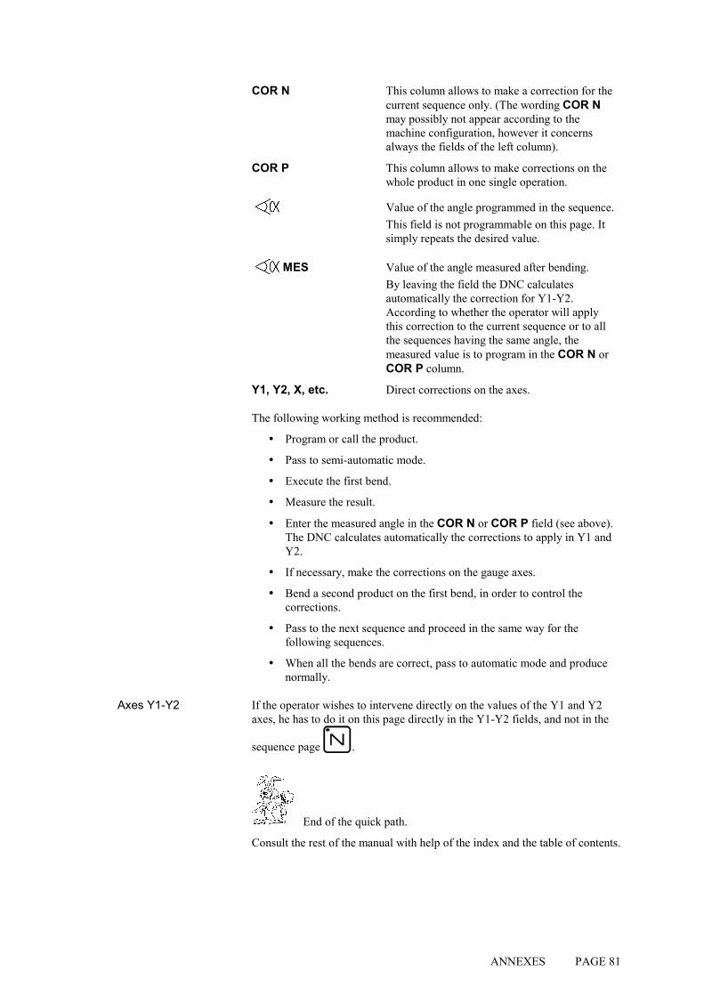
ANNEXES PAGE 81
COR N This column allows to make a correction for the current sequence only. (The wording COR N may possibly not appear according to the machine configuration, however it concerns always the fields of the left column).
COR P This column allows to make corrections on the whole product in one single operation.
Value of the angle programmed in the sequence. This field is not programmable on this page. It simply repeats the desired value.
MES Value of the angle measured after bending. By leaving the field the DNC calculates automatically the correction for Y1-Y2. According to whether the operator will apply this correction to the current sequence or to all the sequences having the same angle, the measured value is to program in the COR N or COR P column.
Y1, Y2, X, etc. Direct corrections on the axes.
The following working method is recommended:
! Program or call the product.
! Pass to semi-automatic mode.
! Execute the first bend.
! Measure the result.
! Enter the measured angle in the COR N or COR P field (see above). The DNC calculates automatically the corrections to apply in Y1 and Y2.
! If necessary, make the corrections on the gauge axes.
! Bend a second product on the first bend, in order to control the corrections.
! Pass to the next sequence and proceed in the same way for the following sequences.
! When all the bends are correct, pass to automatic mode and produce normally.
Axes Y1-Y2 If the operator wishes to intervene directly on the values of the Y1 and Y2 axes, he has to do it on this page directly in the Y1-Y2 fields, and not in the
sequence page .
End of the quick path.
Consult the rest of the manual with help of the index and the table of contents.

PAGE 82 USER GUIDE DNC 60 PS
ALPHANUMERICAL CHARACTERS
The CODE field allows the introduction of alphanumerical characters.
To introduce these characters, the and keys are used, combined with the numerical keys of the keyboard.
Example: To introduce the character A, press the key and keeping the latter held down, press the 0 key.
Here is the correspondence of these keys:
0 1 2 3 4 5 6 7 8 9 --------------------------------------------------------------------------------------------
A D G J M P S V Y \ B E H K N Q T W Z ] C F I L O R U X [ ^
MESSAGES / ERRORS
When passing from programming or manual mode into semi-automatic or automatic mode, the safety systems are verified and any error is mentioned by the impossibility to pass to the chosen mode.
The DNC forces the mode; the cursor positions itself on the field concerned and the interactive field indicates ERROR.
The error must then be corrected and the passage to or mode be tried again. If another error exists the process repeats itself until all the errors have been corrected.
By error we understand the programming of a value not realizable by the DNC (further than the limit switches, collision, etc.).
ANNEXES PAGE 83
THE INTERACTIVE MESSAGES
CASSETTE Indicates that the "cassette" (internal memory) - has not been initialized - is polluted - has changed the format (e.g. by changing the software version). Just "clean" the internal memory by placing the cursor on
the P field, entering 999 and pressing the key.
COMPLETE Displayed in mode when the buffer is full. (No more space for an additional sequence).
COPIED Displayed in mode when a new sequence has been
created at the end of the program using the key.
DELETED Displayed in mode when a product or sequence is
deleted using the key.
END Displayed in or mode, indicates the last sequence of the program.
Err - axes Following error (theoretical trajectory).
Err - FC Limit switch error.
ERROR This message is indicated when a calculation is impossible, or would create out-of-range values. When security measures are in force (in other words when an axis is told to move beyond its authorized limits).
This information is followed by a return to mode and the cursor positions itself automatically over the field to be corrected.
ERROR In the case of a transmission exterior ->DNC, this message indicates that the data received are not valid, and thus impossible to read.
EXECUTED The DNC has made the calculation correctly (corrections, transformations, etc.).
EXISTS Indicates that the product or tool number chosen for storage already exists.
FREE Displayed in mode when the buffer is empty (no

PAGE 84 USER GUIDE DNC 60 PS
sequences programmed).
IGNORE Displayed when the key used cannot (must not) be used at that time.
INSERTED Indicates that the insertion has been made correctly.
Jitter Error caused by the application of simultaneous edges on the input encoder signals (can be provoked by a parasite, a fault in the encoder or a short-circuit on the encoder phases).
LAST Displayed in mode when the sequence shown is the last of the product.
NEXT Is displayed during successive display ( key) of the sequences which exist in the buffer (except for the last sequence which indicates END).
NO ACTIVE Indicates an attempt to change to or mode on a sequence where the CY is programmed at 0.
NO PLACE Indicates that the product list memory has no more space available.
PAUSE Axis pause.
PREVIOUS Same as NEXT but with the key.
RUN Indicates that the transmission is being made correctly. This message flashes slowly for the duration of the transmission.
STOP Indicates that the transmission has been interrupted by means of the DNC STOP key.
STORED Indicates that the storage operation has been made correctly.
synchro The maximum authorized separation (X1<->X2) has been exceeded.
TEACH OK The TEACH operation has been made correctly.
TIME OUT Indicates that the DNC has not received any valid information since the beginning of the transmission, and thus returns the command to the operator. This message appears after about 30 seconds.
TOL ZONE Displayed in or mode when the axes are positioned outside of their tolerances. Generally, just press the start of the front pannel to position the axes will do.

ANNEXES PAGE 85
UNDEFINED Refusal to change to or , if the parameters vital to execution are not or only partially programmed and thus prevent the verification calculations.
Var KO One of the DNC inputs "SERVO DRIVER OK" is not (no longer) active (+24 VDC).
PAGE 86 USER GUIDE DNC 60 PS
PRINT OF THE CURRENT SCREEN
The DNC 60 authorizes, if the RS232 port is included (optional), to print the content of a page displayed on the screen (connector J5).
This allows, through a hardcopy, to retain information regarding the product(s), tools or machine parameters.
To be able to send this information to the printer, it is compulsory that you use a serial printer (RS232).
You have to program the DNC 60 transmission parameters to the printer's required specifications.
Baud rate: 4800 max.
Bits: 7 or 8
Stop bits: 1, 2 etc.
Parity: 1 or leave blank
Protocol : this field defines how many DNC's pages you want to have on one printer's page. After the relevant number the DNC sends a form feed character. Example: 1 = 1 DNC's page per printer'spage. 2 = 2 DNC's pages per printer's page, etc.
BCC: this field defines the left margin in cm. left margin = 2 + (BCC x 2)
Valid range: 0 (2 space characters) to 9 (20 space characters)
Example: BCC = 4, then 2 + (4 x 2) = 10
TO PRINT FROM THE DNC
! Select the relevant page.
! Simultaneously press the stop and correction or menu
keys.

INDEX PAGE 87
INDEX
A
Abbreviations, 5
Access by password, 59, 61 to levels superior to 3, 62
Access levels, 59 Management by external key, 64 Protection, 59 Users, 59
Add a bend, 29
Advanced page, 17
Advanced sequence, 17
Angle, 80 corrections, 80 result out of tolerance, 67, 69
Axis modify the datum, 75
B
Backup, 53
Beam cycle without bend, 79 doesn't descend, 79 reference, 67
Bend cycle without bend, 79
Bend(s) add, 29 delete, 29
Bending bottoming, 80
Bending order, 30
Buffer, 10
C
Calculation, 29
Calibration, 76
Character(s) alphanumerical, 82
Clear key, 16
work memory, 41
Conventions, 5
Copy sequence, 37, 42
Copyright & License agreement, 3
Correction, 14 angle, 80 page, 80 use the page, 37
Criteria, 45
CYBACK, 53
Cycle without bend, 79
D
Datum of an axis, 75
Delete a bend, 29 a punch, 52 key, 16 work memory, 27
Deleting a product, 47 all the products, 47
Die(s), 49 linear force, 50
E
Error explication of the messages, 83
F
Field Al, 24 CAL, 24, 76 CODE, 24 COR, 38 Cr, 39 CR, 26, 38 CY, 38 Dev L, 24 Ext start, 39 F1, 39 F5, 39 FACE, 30 I/mm, 24
PAGE 88 INDEX
Kg/mm², 24 L, 25 LEG, 30 Lmat, 24, 38 MEM, 38 N, 24, 25, 38 P, 23 p/d, 24 P+, 24 POS, 38 Q, 38 ri, 25, 38 Rx, 38 S.S., 24 SET, 75 SP, 39 St, 24 TDC, 39 Th, 24, 38 TOL, 26 TON, 38 Vy , 39
Force linear, 50
I
Ideal curve, 30, 38, 77
Index, 87
Initialization, 65
Insert key, 16
K
Key external, 64 physical, 59 virtual, 59
Keyboard, 13
L
LINK7000, 53, 55
List of dies, 22 of punches, 22 product, 14
M
Manipulation sheet metal, 32
Memory buffer, 10 Flash, 53 internal, 10 internal cassette, 10 work memory, 10
Memory zone, 65
Menu key, 14
Message COPIED, 37 EXISTS, 27, 29, 44 explication of the messages, 83 RUN, 54
Mode automatic, 15 manual, 15 programming, 15 semi-automatic, 15 working, 57
P
Page correction, 80 L-alpha, 23 product status, 23 sequence, 37
Page backwards, 17
Password change, 63 lost, 59 modify, 59
Print screen, 86
Printer, 86
Problem beam doesn't descend, 79 pollution, 65
Product, 14 calling, 46 deleting, 47 list of, 45 programming, 21 searching, 46 searching by criteria, 45
Profile, 23
Programming direct, 21, 37, 40 L-alpha, 21 product, 21 the bending order, 30
Punch(es), 49
INDEX PAGE 89
angle, 50 linear force, 50 reference, 67
Punching, 79
R
REF Y, 50
Reference, 67
Return, 32
RS232, 53 transmission cable, 54
Rules conventions, 5
S
SAF X, 50
Safety, 71
Safety X, 50
Safety instructions, 3
Save product, 27
Saving, 53 product, 46
Screen print screen, 86
Search, 16 by criteria, 14
Searching product, 46 product by criteria, 45
Sequence, 14 copy, 37, 42
Sequence backwards, 17
Serial link, 53
Sheet metal manipulation, 32 thickness measuring, 76
Start, 18
Stop, 18
Store key, 16
Swing, 32
Swivel, 32
T
Teach key, 16
Thickness measuring, 76
Tooling, 49
Tools reference, 67
Transfer, 53
U
Updating, 53
Users, 59 table of ..., 60
W
Warranty, III
Work memory, 10