DNA Size Selection System Operations...
78
DNA Size Selection System Operations Manual
Transcript of DNA Size Selection System Operations...
DNA Size Selection System
Operations Manual

● ●
PippinHT Operations Manual ii 460005 Rev G
Sage Science Inc. Suite 2400 500 Cummings Center Beverly, MA. 01915 © 2018 Sage Science, Inc. All rights reserved. Sage Science and PippinHT are trademarks of Sage Science, Inc. All other brands and name mentioned herein are property of their owners. The PippinHT instrument and gel cassettes are covered by U.S. patents
8,361,298 and 8,361,299. For research use only.
● ●
PippinHT Operations Manual iii 460005 Rev G
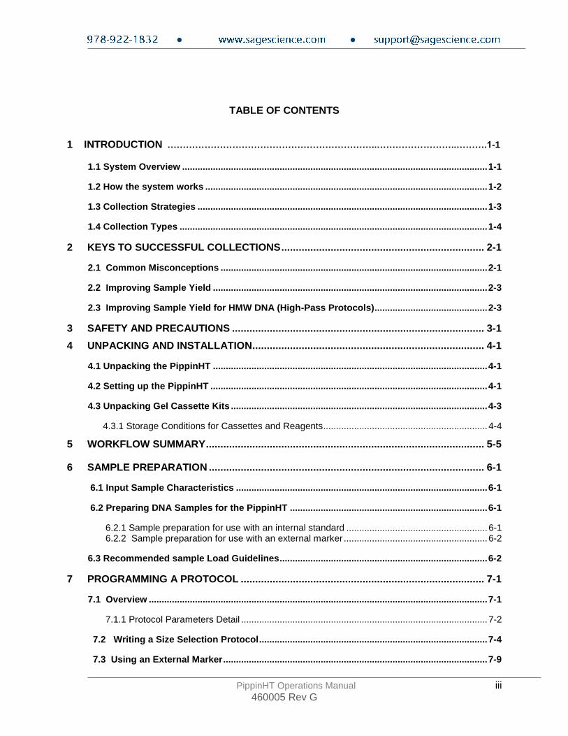
TABLE OF CONTENTS
1 INTRODUCTION …………………………………………………………..……………………..……….1-1
1.1 System Overview ....................................................................................................................... 1-1
1.2 How the system works .............................................................................................................. 1-2
1.3 Collection Strategies ................................................................................................................. 1-3
1.4 Collection Types ........................................................................................................................ 1-4
2 KEYS TO SUCCESSFUL COLLECTIONS ...................................................................... 2-1
2.1 Common Misconceptions ........................................................................................................ 2-1
2.2 Improving Sample Yield ........................................................................................................... 2-3
2.3 Improving Sample Yield for HMW DNA (High-Pass Protocols) ............................................ 2-3
3 SAFETY AND PRECAUTIONS ....................................................................................... 3-1
4 UNPACKING AND INSTALLATION ................................................................................ 4-1
4.1 Unpacking the PippinHT ........................................................................................................... 4-1
4.2 Setting up the PippinHT ............................................................................................................ 4-1
4.3 Unpacking Gel Cassette Kits .................................................................................................... 4-3
4.3.1 Storage Conditions for Cassettes and Reagents................................................................ 4-4
5 WORKFLOW SUMMARY ................................................................................................ 5-5
6 SAMPLE PREPARATION ............................................................................................... 6-1
6.1 Input Sample Characteristics .................................................................................................. 6-1
6.2 Preparing DNA Samples for the PippinHT ............................................................................. 6-1
6.2.1 Sample preparation for use with an internal standard ....................................................... 6-1 6.2.2 Sample preparation for use with an external marker ........................................................ 6-2
6.3 Recommended sample Load Guidelines ................................................................................. 6-2
7 PROGRAMMING A PROTOCOL .................................................................................... 7-1
7.1 Overview .................................................................................................................................... 7-1
7.1.1 Protocol Parameters Detail ................................................................................................ 7-2
7.2 Writing a Size Selection Protocol ......................................................................................... 7-4
7.3 Using an External Marker ....................................................................................................... 7-9
● ●
PippinHT Operations Manual iv 460005 Rev G
CONTENTS (Cont'd)
8 OPTICAL CALIBRATION ................................................................................................ 8-1
9 PREPARING A CASSETTE ............................................................................................ 9-1
10 CONTINUITY TEST ....................................................................................................... 10-1
10.1 Continuity Test Failure and Troubleshooting ..................................................................... 10-2
11 LOADING SAMPLES ................................................................................................... 11-1
11.1 Sample loading best practices ........................................................................................... 11-1
11.2 Sample loading procedure .................................................................................................. 11-2
11.3 Loading less than 12 samples, and reusing a gel cassette ............................................. 11-2
12 RUNNING A PROTOCOL ............................................................................................. 12-1
12.1 Overview ............................................................................................................................... 12-1
12.2 Sample Tracking .................................................................................................................. 12-2
12.2.1 Gel cassette barcodes ................................................................................................ 12-2 12.2.2 Sample ID entry .......................................................................................................... 12-3 12.2.3 Importing Sample IDs ................................................................................................. 12-3 12.2.4 Using the Sample ID Template ................................................................................... 12-5 12.2.5 Log Files ...................................................................................................................... 12-6 12.2.6 Log File Name Format ................................................................................................ 12-7 12.2.7 Adding a Prefix to Log File Names ............................................................................. 12-7
12.3 Starting, Pausing and Run Completion ............................................................................. 12-8
12.4 Monitoring a Run .............................................................................................................. 12-10
12.4.1 Run Status Indicators ............................................................................................... 12-10 12.4.2 Lane Status Indicators ............................................................................................. 12-11 12.4.3 Marker Detection Failure Alert ................................................................................. 12-12
12.5 Manual Mode ...................................................................................................................... 12-14
13 LOG REVIEW ............................................................................................................ 13-1
13.1 Overview .............................................................................................................................. 13-1
13.2 Loading a file ....................................................................................................................... 13-2
14 MANAGING FILES .................................................................................................... 14-1
14.1 Overview ............................................................................................................................. 14-1
14.2 File Types .......................................................................................................................... 14-2
14.3 Transferring files ............................................................................................................... 14-3
15 SYSTEM OPTIONS.................................................................................................... 15-1

● ●
PippinHT Operations Manual v 460005 Rev G
CONTENTS (Cont'd)
16 UPGRADING PIPPINHT SOFTWARE ....................................................................... 16-3
16.1 Extracting the Files to a USB flash drive....................................................................... 16-3
16.2 Upgrading the Pippin Instrument Software.................................................................. 16-4
17 PREVENTATIVE MAINTENANCE – RINSING ELECTRODES ................................. 17-7
17.1 Electrode Rinse Procedure ............................................................................................... 17-7
18 WARRANTY AND SERVICE ..................................................................................... 18-1
19 INSTRUMENT SPECIFICATIONS ............................................................................. 19-1
20 GEL CASSETTES SPECIFICATIONS ....................................................................... 20-1
20.1 3% Agarose, 100 bp-250 bp, Marker 30G....................................................................... 20-2
20.2 2% Agarose, 100 bp-600 bp, Marker 20B ........................................................................ 20-3
20.3 1.5% Agarose, 250 bp-1.5 kb, Marker 15C ...................................................................... 20-4
20.4 1.5% Agarose, High-Pass, >300bp - 1.5kb, Marker 15C…………………………………..20-5
20.5 0.75% Agarose, High-Pass >6-10 kb, Marker 75D........................................................... 20-6
20.6 0.75% Agarose, High-Pass >15-20 kb, Marker 75E ........................................................ 20-7
20.7 0.75% Agarose, High-Pass >30-40 kb, Marker 75F ........................................................ 20-8

● ●
PippinHT Operations Manual 1-1 460005 Rev G
1 Introduction
Thank you for purchasing the PippinHT from Sage Science. The PippinHT is an automated preparative gel electrophoresis system. We urge you to read this manual to familiarize yourself with the system’s capabilities and precautions.
1.1 System Overview
There are three components to the PippinHT system:
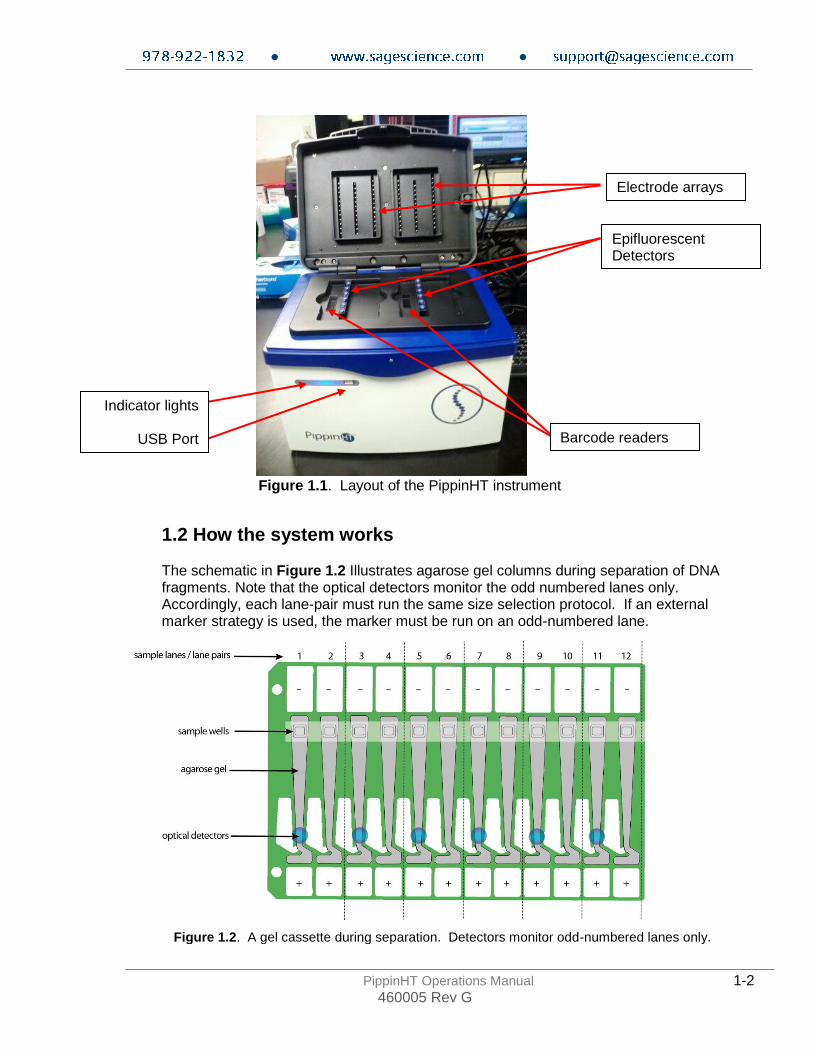
• Instrument – The instrument features two epifluorescent detector arrays, two barcode readers, an electrophoresis power supply, two electrode arrays, and a single-board computer. The system computer is accessed by an external LCD monitor, mouse, and keyboard. (Figure 1-1)
• Software – System software allows the user to:
o Enter parameters that define the DNA fragment size ranges that are to be collected, and enter sample identifications.
o Run the instrument and monitor operations.
o View previous runs with a review screen, and track run data with saved run log files.
• Gel Cassettes – Pre-cast, disposable agarose cassettes are manufactured by Sage Science. Cassettes are supplied in kits that contain 10 cassettes and sufficient reagents to complete all collections. Kits have been developed to address DNA size range collections at various size ranges.
● ●
PippinHT Operations Manual 1-2 460005 Rev G
Figure 1.1. Layout of the PippinHT instrument
1.2 How the system works
The schematic in Figure 1.2 Illustrates agarose gel columns during separation of DNA fragments. Note that the optical detectors monitor the odd numbered lanes only. Accordingly, each lane-pair must run the same size selection protocol. If an external marker strategy is used, the marker must be run on an odd-numbered lane.
Electrode arrays
Epifluorescent Detectors
Barcode readers
Indicator lights
USB Port
Figure 1.2. A gel cassette during separation. Detectors monitor odd-numbered lanes only.
● ●
PippinHT Operations Manual 1-3 460005 Rev G
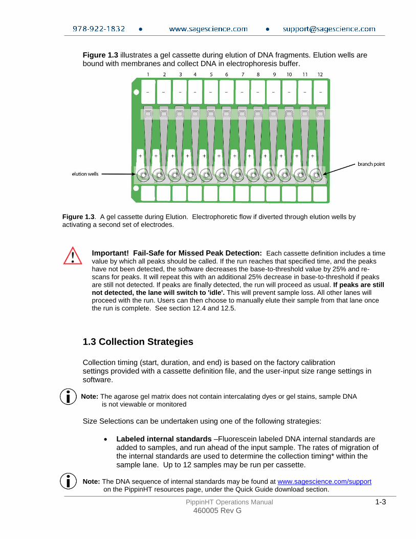
Figure 1.3 illustrates a gel cassette during elution of DNA fragments. Elution wells are bound with membranes and collect DNA in electrophoresis buffer.
Important! Fail-Safe for Missed Peak Detection: Each cassette definition includes a time value by which all peaks should be called. If the run reaches that specified time, and the peaks have not been detected, the software decreases the base-to-threshold value by 25% and re-scans for peaks. It will repeat this with an additional 25% decrease in base-to-threshold if peaks are still not detected. If peaks are finally detected, the run will proceed as usual. If peaks are still not detected, the lane will switch to 'idle'. This will prevent sample loss. All other lanes will proceed with the run. Users can then choose to manually elute their sample from that lane once the run is complete. See section 12.4 and 12.5.
1.3 Collection Strategies
Collection timing (start, duration, and end) is based on the factory calibration settings provided with a cassette definition file, and the user-input size range settings in software.
Note: The agarose gel matrix does not contain intercalating dyes or gel stains, sample DNA is not viewable or monitored
Size Selections can be undertaken using one of the following strategies:
• Labeled internal standards –Fluorescein labeled DNA internal standards are added to samples, and run ahead of the input sample. The rates of migration of the internal standards are used to determine the collection timing* within the sample lane. Up to 12 samples may be run per cassette.
Note: The DNA sequence of internal standards may be found at www.sagescience.com/support on the PippinHT resources page, under the Quick Guide download section.
Figure 1.3. A gel cassette during Elution. Electrophoretic flow if diverted through elution wells by activating a second set of electrodes.

● ●
PippinHT Operations Manual 1-4 460005 Rev G
• Labeled external marker – The fluorescein labeled DNA marker is loaded in a single dedicated sample lane during a run. The rates of migration of the markers are used to determine the collection timing in the remaining sample lanes. At least one DNA marker and up to 11 samples per cassette must be run per cassette.
• Timed runs – The beginning and end time of elution is set by the user. Neither internal standards or external markers are used.
1.4 Collection Types
The PippinHT can be programmed to size select either targeted fractions or “High-Pass” collections. The fragment size distributions are described below: 1. Minimum Size Distribution (“Tight” setting). The
cassette lane will collect the narrowest distribution of fragments that is achievable given the resolution of the agarose gel concentration within the cassette. The distribution is Gaussian, and its range is typically +/- 16% (CV 8%) of the median fragment size.
2. Range Size Distribution (“Range” setting). The
cassette lane will collect a distribution of fragments between a starting base pair value and an ending base pair value. The actual start and end fragment sizes are typically within +/- 10% of the base pair values input into the software.
3. High-Pass Size Distribution (uses “Range*”
setting). The cassette lane will collect all fragments above a base pair threshold. The method increases the average fragment length of the collection depending on threshold value and input DNA distribution profile. High-Pass protocols require an external marker to be run in one lane.
* Although the cassette continues to collect until the end of the run,
an end base pair value will auto-fill in the software protocol field. This value should be disregarded, and should not be changed by users.
High Pass
Range
Tight

● ●
PippinHT Operations Manual 2-1 460005 Rev G
2 Keys to Successful Collections It is recommended that users closely follow the instructions outlined in this manual until they become thoroughly familiar with the system. The Quick Guide (included with cassettes) provides protocol reminders, but is not intended for beginning users.
Keys to successful collections are outlined in the following sections:
• Purity of the input sample (Section 6)
• Optical Calibration (Section 8)
• Preparation of the cassettes (Section 9)
• Sample loading (Section 11)
In addition, extra steps should be taken to improve recovery of high molecular weight collections using High-Pass protocols with 0.75% agarose cassettes. These recommendations are outlined in section 2.3, below.
2.1 Common Misconceptions Users should be aware of the following characteristics of the PippinHT system. These are part of normal operation of the system, but may seem counterintuitive at first.
2.1.1 Narrowest is not always the best. The PippinHT can produce very narrow size distributions from sheared genomic DNA. However, narrower size distributions will necessarily mean that a smaller fraction of the input DNA will be recovered. Users should broaden their collection ranges if the default tight settings do not produce enough DNA for their application.
Figure 2.1. A comparison of the relative sample yield between tight and broader range size selections of DNA.

● ●
PippinHT Operations Manual 2-2 460005 Rev G
2.1.2 DNA undergoing elution is smaller than DNA at the detector. The branch point between the separation and elution channels is downstream from the detector position. Figure 2.2 shows a cassette channel to illustrate. During normal operation, the leading edge of the DNA fraction scheduled for elution passes the detector before the start of elution (by up to several minutes). This offset can give rise to the impression that sample elution is late, even in runs that are functioning properly.
Figure 2.2. An illustration of the time and base pair difference between the detector and branch point.
2.1.3 The rate of electrophoresis is faster in the separation channel than in the elution channel. This may cause misconceptions with regard to the timing of broad size selections. For instance, if one sample is programmed to select from 400 – 600bp, and a second sample is programmed to select from 200 – 600 bp, the narrower range will finish eluting before the broader one, even though both elutions complete collection at 600 bp. The collections of large DNA fragments, especially with pulsed –field protocols, can also appear counter-intuitive with respect to timing.
Figure 2.3. An illustration comparing the relative rate of electrophoresis in the separation and elution channels

● ●
PippinHT Operations Manual 2-3 460005 Rev G
2.2 Improving Sample Yield
Users should expect an intrinsic yield of between 50-80% of the sample input. This is based on product validation studies in which restriction fragments have been run and collected, and the respective DNA amounts compared.
Yield can be affected by DNA becoming lightly bound to the low molecular weight cut-off membrane in the elution well. At the end of the run, the PippinHT will briefly reverse field (for 5 seconds) in every elution channel. This improves sample yield by up to 20%.
Note: The reverse field feature may be disabled in the Systems Option screen.
2.3 Improving Sample Yield for HMW DNA (High-Pass Protocols)
Recovering high molecular weight DNA from High-Pass protocols tend to have lower yields than low molecular weight size selection. The following additional steps are highly recommended to improve product yield:
1. Wait at least 45 min after termination of the run before removing eluted DNA (it is OK to leave samples in instrument for hours, i.e. for an overnight run).
2. Rinse the elution well with Tween solution. Tween solution (0.1% Tween 20 in electrophoresis buffer) is provided by Sage Science with cassette kits used with HMW collections. After removing the initial eluted volume:
• Remove the eluted sample from elution well at the end of the run
• Add 30l of Tween solution (supplied with the gel cassettes) to the elution well
• Wait 1 minute
• Remove solution and pool with the original extracted sample, or process separately
.

● ●
PippinHT Operations Manual 3-1 460005 Rev G
3 Safety and Precautions
Icons Used
In this manual, the following icons will be used to provide the user with information pertinent to the use of the PippinHT.
Caution! Warns the user that injury or instrument damage may occur if the contents of the warning are not properly followed.
High Voltage! Warns of the risk of electrical shock if the contents of the warning are not properly followed.
Important! Provide important information about the proper use of the system that may influence the quality of the result.
Note. Provides additional information regarding the function of the system or applications for which is used. Caution! Class I invisible Laser Radiation Present. Avoid long-term viewing of laser.
Safe Use Guidelines
The PippinHT system is designed to operate under the following environmental conditions:
• Pollution Degree 2
• Installation category 2
• Altitude 2000m
• Indoor use
• Ambient temperature 17-22oC
• Humidity 10-80%, non-condensing
Standard laboratory precautions should be taken when handling PippinHT Gel cassettes and operating the PippinHT:
• Wear a lab coat, safety glasses, and gloves.
• Use in proximity of an eye wash station and/or running water.
Caution! The PippinHT was designed to be operated on a flat surface. Do not operate on a tilted surface or tilt during operation.

● ●
PippinHT Operations Manual 4-1 460005 Rev G
4 Unpacking and Installation
4.1 Unpacking the PippinHT The PippinHT instrumentation is shipped in two boxes. One will contain the PippinHT and accessories. The second box will contain the computer monitor in the manufacturer’s original packaging. With the boxes in the upright position, open and confirm that the following items are enclosed:
Monitor
• LCD computer monitor (1366 x 768)
• Video cable
• Power cord
PippinHT
• PippinHT Instrument
• Accessory box o Computer keyboard, USB o Computer mouse, USB o Power supply o Power cord o Mouse Pad o Operations Manual o USB Memory Stick o Two rinse cassettes (for maintenance of electrodes) o Two calibration fixtures (for setting optical baseline before each run)
4.2 Setting up the PippinHT
1. Remove the accessory box located just inside the instrument packaging from a cardboard shelf atop the instrument. Remove the keyboard, mouse, and instrument power supply from their packaging.
2. Remove the cardboard shelf from the box.
3. Remove the foam insert at the top of the instrument.
4. Reach into the box and grab the instrument from the bottom. The PippinHT weighs approximately 20 lbs. Place the instrument onto a table or bench top.
5. Return the foam inserts and cardboard shelf to the box. If feasible, place the box in storage.
● ●
PippinHT Operations Manual 4-2 460005 Rev G
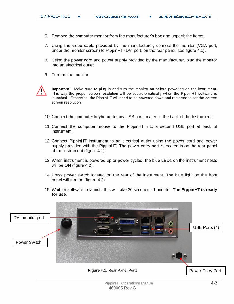
6. Remove the computer monitor from the manufacturer’s box and unpack the items.
7. Using the video cable provided by the manufacturer, connect the monitor (VGA port,
under the monitor screen) to PippinHT (DVI port, on the rear panel, see figure 4.1).
8. Using the power cord and power supply provided by the manufacturer, plug the monitor into an electrical outlet.
9. Turn on the monitor.
Important! Make sure to plug in and turn the monitor on before powering on the instrument. This way the proper screen resolution will be set automatically when the PippinHT software is launched. Otherwise, the PippinHT will need to be powered down and restarted to set the correct screen resolution.
10. Connect the computer keyboard to any USB port located in the back of the Instrument.
11. Connect the computer mouse to the PippinHT into a second USB port at back of instrument.
12. Connect PippinHT instrument to an electrical outlet using the power cord and power
supply provided with the PippinHT. The power entry port is located is on the rear panel of the instrument (figure 4.1).
13. When instrument is powered up or power cycled, the blue LEDs on the instrument nests
will be ON (figure 4.2).
14. Press power switch located on the rear of the instrument. The blue light on the front panel will turn on (figure 4.2).
15. Wait for software to launch, this will take 30 seconds - 1 minute. The PippinHT is ready
for use.
Power Entry Port
Power Switch
Figure 4.1. Rear Panel Ports
USB Ports (4)
DVI monitor port

● ●
PippinHT Operations Manual 4-3 460005 Rev G
4.3 Unpacking Gel Cassette Kits
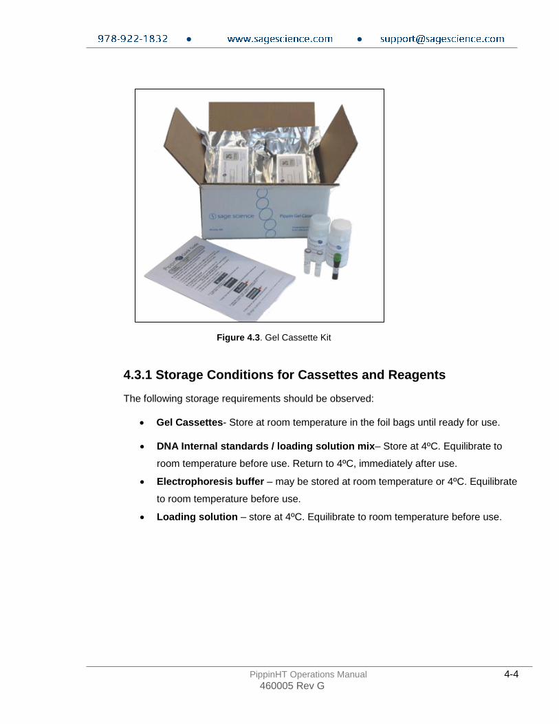
Gel cassettes are shipped in boxes with the following items. Ensure boxes are in the upright position and confirm that following contents are present:
o 10 or 4 foil-sealed gel cassettes (store at R.T.) o 1 package of adhesive tape for sealing elution wells o User Quick Guide o Reagent kits (divide volumes by half for 4-cassette kits) (store at 4ºC)
3%, 2% or 1.5% agarose cassettes:
Package 1
• 1200 μl fluorescein-labeled DNA internal standards/ loading solution mix (5 μl/sample)
• 2 x 60 ml of Electrophoresis Buffer
Package 2
• 2 x 600 μl of loading solution (packaged separately) – for size selection using an external marker
0.75% agarose cassettes (uses external markers only)
▪ 500 μl fluorescein-labeled marker solution (25ul per lane) ▪ 2 x 60 ml of Electrophoresis Buffer
▪ 4 X 800l of 0.1% Tween20 in running buffer. Tween solution is used to improve recovery of large DNA fragments.
Important! Fluorescein labels will degrade at room temperature – minimize time at RT for labeled standards and markers
Nest LED lights turn ON when the instrument is powered up.
When running, a green light is also indicated on the front panel.
After the power button is pressed, the blue front panel LED will light, and the software will launch.
Figure 4.2. Instrument indicator lights and optical array.
● ●
PippinHT Operations Manual 4-4 460005 Rev G
4.3.1 Storage Conditions for Cassettes and Reagents
The following storage requirements should be observed:
• Gel Cassettes- Store at room temperature in the foil bags until ready for use.
• DNA Internal standards / loading solution mix– Store at 4ºC. Equilibrate to
room temperature before use. Return to 4ºC, immediately after use.
• Electrophoresis buffer – may be stored at room temperature or 4ºC. Equilibrate
to room temperature before use.
• Loading solution – store at 4ºC. Equilibrate to room temperature before use.
Figure 4.3. Gel Cassette Kit

● ●
PippinHT Operations Manual 5-5 460005 Rev G
5 Workflow Summary
Prepare samples add loading solution/standard mix to samples (max. 12 samples/cassette)
Use internal standard or external marker?
internal standard
High-Pass protocol?*
Yes
No
Prepare samples add loading solution to samples prepare external marker (3,2,&1.5% cassettes) or bring external marker solution to RT (0.75%/High-Pass cassettes) (max.11 samples/cassette)
external marker
Program a Size Selection Protocol Select “USE INTERNAL STANDARDS”
Program a Size Selection Protocol Enter reference lane No. for the external marker Select “APPLY TO ALL LANES”
Calibrate the Optics
Prepare the Cassette(s)
Run the Continuity Test on the Cassette(s)
Load Samples onto the Cassette(s)
Run the PippinHT
* 0.75% agarose cassettes are used for High-Pass collections only.
● ●
PippinHT Operations Manual 6-1 460005 Rev G
6 Sample Preparation
6.1 Input Sample Characteristics When running the PippinHT™, characteristics of input DNA can affect separation resolution and efficiency of product recovery. The following general guidelines should be followed:
• Ionic strength: The ionic strength of the sample should be lower than the ionic strength of the buffer (80mM monovalent ions). High salt concentrations can result in unpredictable DNA mobility.
• Protein in the sample: DNA-binding proteins such as ligases or polymerases can affect the mobility of fragments during separation. Proteins can also reduce DNA recovery from the elution module by increasing the binding of DNA to the ultrafiltration membrane at the back of the elution module. For best results, samples should be de-proteinized prior to loading whenever possible.
• Input DNA size distribution: A knowledge of the input size distribution is obviously important to program accurate size selection settings. PippinHT cassettes are calibrated using the Agilent Bioanalyzer to evaluate input and product sizes, and so, for best results, input size distributions should be evaluated using the Bioanalyzer. For low concentration samples, the Agilent HS chip is very useful .
6.2 Preparing DNA Samples for the PippinHT
The marker provided with the PippinHT reagent kit may be used as either an internal or external marker. The method of sample preparation is dependent on the type of marker used.
6.2.1 Sample preparation for use with an internal standard 1. Bring the DNA sample up to 20 µl with TE.
2. Bring the Standard/Loading-solution mix to room temperature (return to 4°C
immediately after use).
3. For each sample, combine 20 µl of sample with 5 µl of Standard/Loading-solution
mix.
4. Mix thoroughly by vortexing and centrifuge briefly.
● ●
PippinHT Operations Manual 6-2 460005 Rev G
6.2.2 Sample preparation for use with an external marker
Prepare the DNA samples 1. Bring the DNA sample up to 20 µl with TE.
2. Bring the loading solution to room temperature.
3. For each sample, combine 20 µl of sample with 5 µl of loading solution.
4. Mix thoroughly by vortexing and centrifuge briefly.
5. Prepare external marker as described below.
Prepare the external marker
A. For 3%, 2%, and 1.5% agarose gel cassettes:
1. Bring DNA standard/loading solution mix to room temperature (return to 4°C
immediately after use).
2. For each external marker, combine 5 µl DNA standard/loading solution mix with
20 µl of TE.
3. Mix thoroughly by vortexing and centrifuge briefly.
B. For 0.75% agarose gel cassettes (High-Pass size selection)
1. Bring the external marker solution to room temperature.
6.3 Recommended sample Load Guidelines
Maximum Load: 1.5 g sheared genomic DNA
Minimum Load: 15 ng sheared genomic DNA
● ●
PippinHT Operations Manual 7-1 460005 Rev G
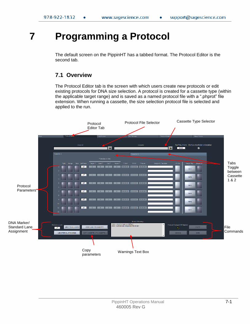
7 Programming a Protocol The default screen on the PippinHT has a tabbed format. The Protocol Editor is the second tab.
7.1 Overview The Protocol Editor tab is the screen with which users create new protocols or edit existing protocols for DNA size selection. A protocol is created for a cassette type (within the applicable target range) and is saved as a named protocol file with a “.phprot” file extension. When running a cassette, the size selection protocol file is selected and applied to the run.
Protocol Editor Tab
Protocol File Selector
Protocol Parameters
File Commands
Warnings Text Box
DNA Marker/ Standard Lane Assignment
Tabs Toggle between Cassette 1 & 2
Copy parameters
Cassette Type Selector

● ●
PippinHT Operations Manual 7-2 460005 Rev G
7.1.1 Protocol Parameters Detail The protocol parameters section is shown below. Size selection must are entered for lane pairs and different values may be entered for each lane pair. The odd-numbered lanes are the lanes which are optically detected.
The function of the columns or fields are provided below. From left-to-right: Programming Modes The user selects which of the three size selection modes that will be used. When this is selected, the editable fields will appear in the size selection parameters:
• Tight - collects the narrowest fragment distribution that can be collected by the system. The user enters a target base-pair value (the median for the distribution) in the size selection parameters.
• Range – collects a fragment range. The user enters a start and end base-pair value in the size selection parameters.
Note: Range mode is used for programming High-Pass protocols.
• Time – collects fragments base on a starting elution time (time after the
beginning of a run) and ending elution time.
Note: Programming modes may be independently applied to individual sample lanes
Programming Modes
Size selection parameters
(in base pairs)
Time-mode parameters
Cassette 2 Tab
● ●
PippinHT Operations Manual 7-3 460005 Rev G
Ref Lane This indicates which lane is used for an internal standard or external marker. The default is off. Internal standard runs will display the same lane number as the parameter field. For external marker runs, each field will display the lane number into which the marker was designated to be loaded. Size Selection Parameters Users enter the size selection parameters in these fields, in base-pairs, based on the programming mode that was selected. The “Pause” field pauses the instrument to allow users to collect two serial collections. The value in the Pause field must be a value within the size range selected (i.e. if a 200-400 bp range is selected, the Pause value must be between 201 and 399). Time Mode Parameters Users enter the size selection parameters, as time (hh:mm:ss) after the start of a run. The Pause value must be within the start time and end time that were entered (T Start and T End). Sample ID Template Users can optionally enter Sample ID Template text. These fields are stored with the saved protocols and appear in the Sample ID field whenever the protocol is used. If sample information is entered or imported into the Sample ID field in the Main screen, then the Sample ID Template names will prefix the Sample ID names. LED On The LED On button allows users to ensure the LED detector remains on in the designated lane-pair for the entirety of the run. This feature is for advance users and non-standard runs. Under normal operation, LED are automatically turned off after the internal standards or external marker has been detected by the instrument. Range Flag The Range Flag is an visual indicator of type of size selection. Tight collection display green and range collections above the minimum distributions indicate an orange color and the word “ Broad”. If a range distribution is selected that is below the achievable minimum distribution, the display will indicate a yellow color and the word “Narrow”. Timed mode selections do not indicate a range flag. Note: Size selections can be entered that are below the minimum possible. In these instances, the range flag will indicate a yellow color and the word “narrow”. These collections will not have a narrower fragment distribution, but the specified minimum with a lower yield:
Pause On The Pause On displays a light gray color if the pause feature has been enabled for that lane-pair.
● ●
PippinHT Operations Manual 7-4 460005 Rev G
7.2 Writing a Size Selection Protocol The procedure below describes programming using internal standards. Users should also follow this procedure if using external markers, and then read section 7.3 for specific information about using external markers.
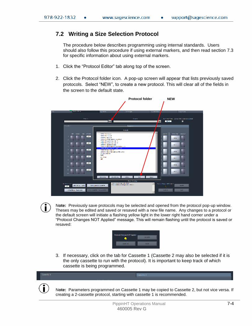
1. Click the “Protocol Editor” tab along top of the screen.
2. Click the Protocol folder icon. A pop-up screen will appear that lists previously saved
protocols. Select “NEW”, to create a new protocol. This will clear all of the fields in
the screen to the default state.
Note: Previously save protocols may be selected and opened from the protocol pop-up window. Theses may be edited and saved or resaved with a new file name. Any changes to a protocol or the default screen will initiate a flashing yellow light in the lower right hand corner under a “Protocol Changes NOT Applied” message. This will remain flashing until the protocol is saved or resaved:
3. If necessary, click on the tab for Cassette 1 (Cassette 2 may also be selected if it is
the only cassette to run with the protocol). It is important to keep track of which cassette is being programmed.
Note: Parameters programmed on Cassette 1 may be copied to Cassette 2, but not vice versa. If creating a 2-cassette protocol, starting with cassette 1 is recommended.
Protocol folder NEW
● ●
PippinHT Operations Manual 7-5 460005 Rev G
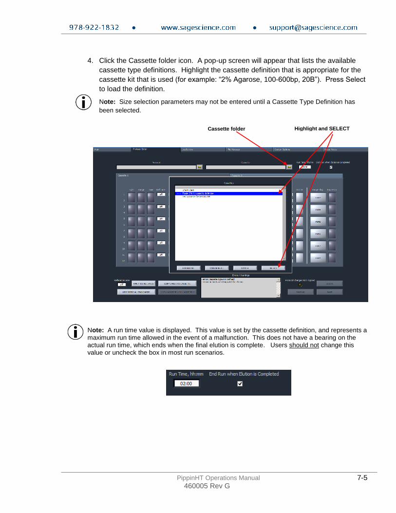
4. Click the Cassette folder icon. A pop-up screen will appear that lists the available
cassette type definitions. Highlight the cassette definition that is appropriate for the
cassette kit that is used (for example: “2% Agarose, 100-600bp, 20B”). Press Select
to load the definition.
Note: Size selection parameters may not be entered until a Cassette Type Definition has
been selected.
Note: A run time value is displayed. This value is set by the cassette definition, and represents a maximum run time allowed in the event of a malfunction. This does not have a bearing on the actual run time, which ends when the final elution is complete. Users should not change this value or uncheck the box in most run scenarios.
Cassette folder Highlight and SELECT

● ●
PippinHT Operations Manual 7-6 460005 Rev G
5. Enter the size selection parameters for lane pair 1-2. Examples are provided below:
• Tight – collects minimum allowable distribution range of DNA fragments using the median target base pair value.
• Range – allows users to select a wider range to be collected using starting and ending base pair values.
Note: Range mode is used for programming High-Pass protocols.
• Time – allows users to program extractions using the starting and ending elution time (hh:mm:ss) values only (a reference DNA marker is not used)
6. Enter Sample ID Template information (optional). These will be saved with the protocol
and prefix to Sample ID information imported (also optionally) into the Main screen when initiating a run.

● ●
PippinHT Operations Manual 7-7 460005 Rev G
7. Press “COPY LANE 1 TO CASSETTE” to copy the size selection parameters to the
remaining lane pairs on Cassette 1.
Note: Each lane pair may be programmed separately with different parameters. Only lanes 1-2 may be copied, however.
COPY LANE 1 TO CASSETTE

● ●
PippinHT Operations Manual 7-8 460005 Rev G
8. Press the USE INTERNAL STANDARDS button to assign size selection based on the internal standard run within its lane-pair. Note: Refer to the next section (7.3) for instructions on using and external marker.
9. Press the “Cassette 2” tab. This will present the Cassette 2 screen for programming or editing.
10. Press COPY CASSETTE 1 TO CASSETTE 2 to copy the size selection parameters (including the Sample ID Template information) applied to cassette 1 to cassette 2.
Note: Cassette 2 may be programmed separately (or edited after copying) with different parameters. Warning! The copy functions will overwrite any pre-entered values.
11. Press SAVE AS to save the protocol. A pop-up window will appear that displays the protocols folder. Enter a file name and press OK.
Internal standard assignment will display the odd numbered lanes in the “Ref Lane” column

● ●
PippinHT Operations Manual 7-9 460005 Rev G
7.3 Using an External Marker
An external marker can be used to calibrate the size selection in the remaining lanes of a cassette. To do this, each cassette kit is supplied with loading solution (in lieu of
the internal standard/loading solution mix) to add as a densifying agent (5 l) to the
DNA samples (20 l) - see Section 5 . An external marker is made by adding
standard/loading solution mix (5 l) to TE (20 l). The marker may then be loaded into the optically detected lane (any odd numbered lane), and the remaining lane pairs will use the marker to calibrate the elution timing. For 0.75% agarose gel cassettes the marker is provide pre-made and ready to load (the cassettes are used for High-Pass protocols, and are only used with external markers)
1. Allocate a lane (lane 1 is recommended) into which the external marker will be loaded.
2. On the Protocol Editor screen, select that lane in the “Reference Lane” field in the
marker assignment area.
3. Press the APPLY TO ALL LANES button to assign size selection in remaining lanes
based on the external marker designated lane.
The reference lane should appear in every “Ref Lane” field when using an external marker

● ●
PippinHT Operations Manual 7-10 460005 Rev G
4. Make sure the reference lane-pair programming modes are off. Note: The lane-pair used for an external marker may be used for size selection as well, provided Start value (not the Target value) is higher than any other Start value in the remaining lanes. Users should be very careful when doing this.
5. Refer to back to Section 7.2 for the remaining instruction for programming a protocol.
Programming modes should be off

● ●
PippinHT Operations Manual 8-1 460005 Rev G
8 Optical Calibration
The PippinHT optical system must be calibrated before every run. The instrument is supplied with two calibration fixtures that fit over the LED detectors on the optical nest. Important! The LED optical array turns off after detecting internal standard peaks. This ensures that there is no possibility of DNA nicking from the light source. Therefore it is critical that the LEDs are calibrated anew before each run. The LEDs will be OFF after a run, and ON after calibration and prior to a run.
1. Press the Main tab.
2. Place the calibration fixture(s) over the optical arrays on each of the nest(s). Ensure that
all LED detectors are covered. The dark side of the fixture must be down (closest to the LEDs):

● ●
PippinHT Operations Manual 8-2 460005 Rev G
3. Close the lid.
4. From the main screen click CALIBRATE.
5. An “LED Calibration” window will launch. The “Calibration Status” field will contain the
message “Ready for calibration”. Press CALIBRATE.
6. The LED photocurrents will automatically adjust to a factory setting, and the “Calibration
Status” field will contain the message “Calibration OK”.
7. Press EXIT to return to the Main Tab.

● ●
PippinHT Operations Manual 9-1 460005 Rev G
9 Preparing a Cassette
1. Remove the cassette from foil packaging. Foil package is scored at one end to allow tearing.
2. Inspect the gel columns. Inspect the cassette from the top and underneath. Look for any obvious breakage in any of the gel columns.
3. Dislodge bubbles from behind the elution modules. Hold the cassettes sideways,
with the sample wells up, and gently tap the side of the cassette. Use the schematic below as a guide.
Dislodge bubbles upwards from behind the elution wells
Tap the side of the cassette

● ●
PippinHT Operations Manual 9-2 460005 Rev G
4. In the lower buffer chamber, move bubbles from behind to the gel column, to the electrode port. Tilt the cassette at a slight angle, witht the elution port side up. Gently tap the top of the cassette to dislodge bubbles from behind the gel column to below the electrode port openings.
5. Remove adhesive strips from cassette. With the cassette on the benchtop, place one hand on the cassette, and hold it firmly. Grab the white tab of the tape and pull the strip firmly and slowly until they are removed.
6. Remove buffer from the upper electrode buffer chambers
a. For 3%, 2% or 1.5% gel cassettes, remove 80 μl. b. For 0.75% gel cassettes, remove 150 μl .
Dislodge bubbles from behind the gel column to the electrode port
Tilt slightly and tap the top of the cassette
Remove buffer

● ●
PippinHT Operations Manual 9-3 460005 Rev G
7. Remove all buffer from elution modules and replace with 30μl of fresh electrophoresis buffer. Replenishing the buffer ensures proper electrophoretic continuity. When refilling empty modules, place tip all the way into the module and slowly fill from the bottom, withdrawing the pipette tip while dispensing, and taking care not to generate any bubbles that can occlude the current path. Use spare buffer that has been supplied with the cassette package, or pipette from the buffer chambers.
Important! Make sure that the pipette tips extend all the way to the bottom of the elution modules without sealing the elution port opening. If the tips seal the port opening, it will be extremely difficult, or impossible, to empty and refill the elution module completely. Test tip fit using the empty rinse cassette supplied with the instrument.
8. Seal the elution wells with the adhesive tape strips. Tape for sealing the elution wells
are supplied with cassette packaging. Long elutions will cause the elution wells to overflow if not sealed. Place tape over the elution wells and rub firmly to fix the tape in position. For best results, rub the tape at the boundary of the well with a smooth hard object such as the back end of a lab marker pen.
9. Place the cassette(s) onto the PippinHT nest(s)
Remove all buffer from elution wells and replace with 30μl of fresh buffer.
● ●
PippinHT Operations Manual 10-1 460005 Rev G
10 Continuity Test
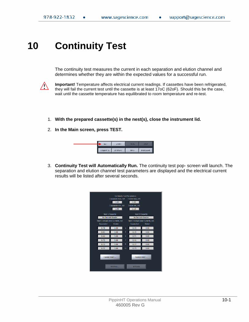
The continuity test measures the current in each separation and elution channel and determines whether they are within the expected values for a successful run. Important! Temperature affects electrical current readings. If cassettes have been refrigerated, they will fail the current test until the cassette is at least 17oC (62oF). Should this be the case, wait until the cassette temperature has equilibrated to room temperature and re-test.
1. With the prepared cassette(s) in the nest(s), close the instrument lid.
2. In the Main screen, press TEST.
3. Continuity Test will Automatically Run. The continuity test pop- screen will launch. The separation and elution channel test parameters are displayed and the electrical current results will be listed after several seconds.
● ●
PippinHT Operations Manual 10-2 460005 Rev G
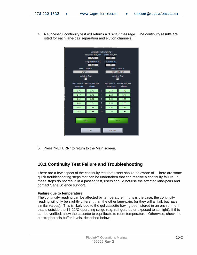
4. A successful continuity test will returns a “PASS” message. The continuity results are listed for each lane-pair separation and elution channels.
5. Press “RETURN” to return to the Main screen.
10.1 Continuity Test Failure and Troubleshooting
There are a few aspect of the continuity test that users should be aware of. There are some quick troubleshooting steps that can be undertaken that can resolve a continuity failure. If these steps do not result in a passed test, users should not use the affected lane-pairs and contact Sage Science support. Failure due to temperature: The continuity reading can be affected by temperature. If this is the case, the continuity reading will only be slightly different than the other lane-pairs (or they will all fail, but have similar values). This is likely due to the gel cassette having been stored in an environment that is outside the 17-22oC operating range (e.g. refrigerated or exposed to sunlight). If this can be verified, allow the cassette to equilibrate to room temperature. Otherwise, check the electrophoresis buffer levels, described below.
● ●
PippinHT Operations Manual 10-3 460005 Rev G
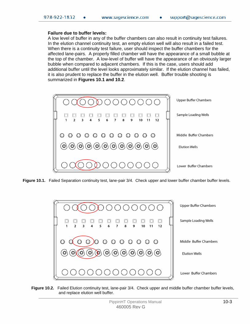
Failure due to buffer levels: A low level of buffer in any of the buffer chambers can also result in continuity test failures. In the elution channel continuity test, an empty elution well will also result in a failed test. When there is a continuity test failure, user should inspect the buffer chambers for the affected lane-pairs. A properly filled chamber will have the appearance of a small bubble at the top of the chamber. A low-level of buffer will have the appearance of an obviously larger bubble when compared to adjacent chambers. If this is the case, users should add additional buffer until the level looks approximately similar. If the elution channel has failed, it is also prudent to replace the buffer in the elution well. Buffer trouble shooting is summarized in Figures 10.1 and 10.2.
Figure 10.1. Failed Separation continuity test, lane-pair 3/4. Check upper and lower buffer chamber buffer levels.
Figure 10.2. Failed Elution continuity test, lane-pair 3/4. Check upper and middle buffer chamber buffer levels, and replace elution well buffer.

● ●
PippinHT Operations Manual 11-1 460005 Rev G
11 Loading Samples
11.1 Sample loading best practices
Proper sample loading is critical for best performance of PippinHT cassettes. For maximum reproducibility and accuracy, the sample should travel through the central section of the gel column, and should be bounded on all four sides by uniformly conductive media – either gel or electrophoresis buffer. The goal of the loading procedure is to produce this geometry in the sample loading well, as illustrated in the top
section of figure 11.1. Properly prepared samples will be 25 l in total volume consisting
of 20 l of DNA mixed with 5 l of loading solution/internal standard mix. The loading solution contains concentrated Ficoll as a densifying agent, and therefore the samples will sink and form a high density layer beneath the electrophoresis buffer when pipetted slowly into the sample wells. If there is insufficient conductive buffer over the sample, the electrophoretic forces lines will curve upward as the sample exits the well (see figure 11.1, bottom section), and the sample will be drawn to the top of the cassette where it can travel out of the gel into the gap between the gel column and the plastic top of the channel. Sample moving in this gap will travel at a different rate than the sample inside the gel column, and will lead to elution of undesired size fractions in the eluted material. In such cases, the contaminating DNA will usually (but not always) be higher in molecular weight than the selected DNA.
Figure 11.1. An illustration of the electrophoretic effect on a DNA sample when a sample well in not completely filled.

● ●
PippinHT Operations Manual 11-2 460005 Rev G
11.2 Sample loading procedure
1. Re-check the buffer level in the sample wells. Make sure that sample wells are completely full to the top with electrophoresis buffer. Top off with additional buffer, if necessary.
2. Remove 30μl of buffer the samples wells. Take care not pierce the agarose with the
pipette tip(s). There is gel on all sides and bottom of the sample well. In addition, there is an agarose “chimney” surrounding the top of the sample well that protrudes up through the cassette cover (see Figure 11.1). When removing buffer, some users find it useful to immerse the pipette tip just below the surface of the buffer and follow the liquid level down with the tip as the buffer is removed. When buffer removal is completed, there will be ~10ul of buffer left in the well.
3. Load 25μl of sample to the sample wells. When adding sample, place tip of pipette just
below the surface of the buffer, and follow the liquid level up with the tip as the well fills. Don’t be concerned if the sample well slightly overfills. The density of the sample will allow it to sink before it can flow out of the well.
11.3 Loading less than 12 samples, and reusing a gel cassette
It is possible to run less than 12 samples on a PippinHT gel cassette. When a size selection protocol is programmed, only the lane-pairs which have been assigned a function (size selection or external marker) will be used. Any remaining lane-pairs can be resealed (with PCR tape, such as MicroSeal A or similar) and reused at a later time up to the expiration date of the cassette.
There are some very important considerations when running a partial gel cassette:
• Users should double-check that the size selection protocol matches the lane-pairs that will be loaded.
• Users should double-check that the unused lanes are de-selected in the size selection protocol (Figure 11.2)
• Tightly reseal the unused lane ports with PCR tape after the initial run
• Clearly mark the unused lanes with a lab marker
Figure 11.2. A de-selected lane-pair. The programming mode and “Ref Lane” field must be OFF.
● ●
PippinHT Operations Manual 12-1 460005 Rev G
12 Running a Protocol
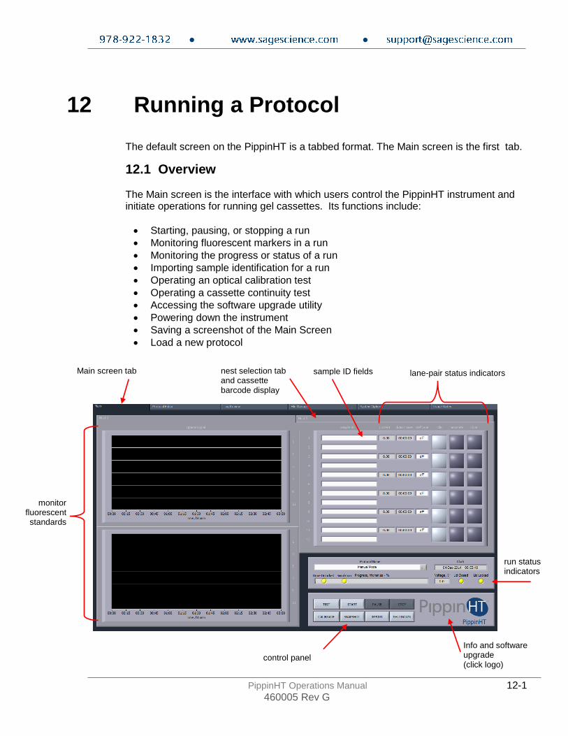
The default screen on the PippinHT is a tabbed format. The Main screen is the first tab.
12.1 Overview The Main screen is the interface with which users control the PippinHT instrument and initiate operations for running gel cassettes. Its functions include:
• Starting, pausing, or stopping a run
• Monitoring fluorescent markers in a run
• Monitoring the progress or status of a run
• Importing sample identification for a run
• Operating an optical calibration test
• Operating a cassette continuity test
• Accessing the software upgrade utility
• Powering down the instrument
• Saving a screenshot of the Main Screen
• Load a new protocol
Main screen tab nest selection tab and cassette barcode display
sample ID fields
lane-pair status indicators
run status indicators
Info and software upgrade (click logo)
monitor fluorescent standards
control panel
● ●
PippinHT Operations Manual 12-2 460005 Rev G
12.2 Sample Tracking
Sample tracking is facilitated at several levels including barcoding, sample ID importing, and log files.
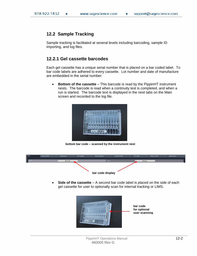
12.2.1 Gel cassette barcodes Each gel cassette has a unique serial number that is placed on a bar coded label. To bar code labels are adhered to every cassette. Lot number and date of manufacture are embedded in the serial number:
• Bottom of the cassette – This barcode is read by the PippinHT instrument nests. The barcode is read when a continuity test is completed, and when a run is started. The barcode text is displayed in the nest tabs on the Main screen and recorded to the log file.
• Side of the cassette – A second bar code label is placed on the side of each gel cassette for user to optionally scan for internal tracking or LIMS.
bottom bar code – scanned by the instrument nest
bar code display
bar code for optional user scanning

● ●
PippinHT Operations Manual 12-3 460005 Rev G
12.2.2 Sample ID entry
Sample ID information may be entered in the Sample ID field for both cassettes that are run on the PippinHT. Information may be entered in any of these ways:
• Keyed in manually – use the Tab key scroll down fields and Shift-Tab to scroll up fields.
• Scanned in with a barcode wand – a bar code wand may be use with the USB port on the front or back of the PippinHT to scan bar coded sample IDs from a traveler or sample sheet.
• Imported via .txt file from a USB port— see below for instructions.
12.2.3 Importing Sample IDs
1. Save up to 12 sample ID names into a text (.txt) file as shown below.
2. Place the file onto a USB drive and insert the drive into any USB port on the PippinHT.
Sample ID fields

● ●
PippinHT Operations Manual 12-4 460005 Rev G
3. In Main screen, press IMPORT on the control panel, a pop-up window will appear.
4. In the pop-up window, select the sample ID file and press IMPORT.
5. Press Exit and verify that the information has been imported.
Highlight file
● ●
PippinHT Operations Manual 12-5 460005 Rev G
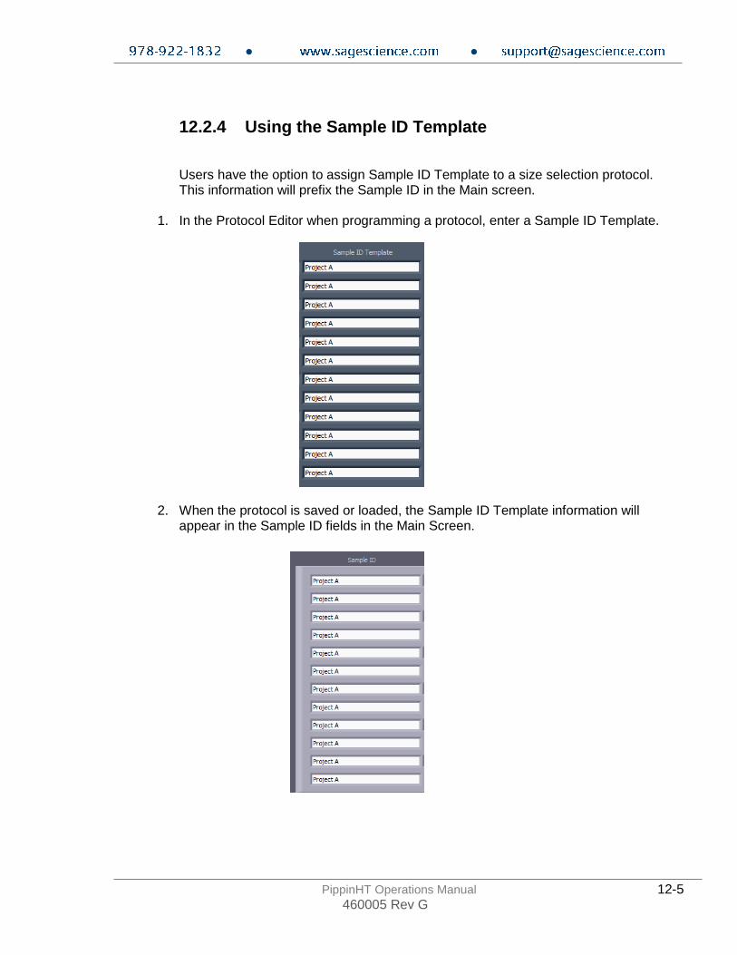
12.2.4 Using the Sample ID Template
Users have the option to assign Sample ID Template to a size selection protocol. This information will prefix the Sample ID in the Main screen.
1. In the Protocol Editor when programming a protocol, enter a Sample ID Template.
2. When the protocol is saved or loaded, the Sample ID Template information will appear in the Sample ID fields in the Main Screen.

● ●
PippinHT Operations Manual 12-6 460005 Rev G
3. When sample IDs are imported (see the previous section 12.2.3), the text fields will concatenate with the Sample ID Template as a prefix.
12.2.5 Log Files
Several log files are automatically saved after key operations on the PippinHT:
• Optical Calibration -- at the end of every optical calibration routine, a screenshot of the result is saved as a .png file.
• Continuity Test – at the end of every continuity test, a screenshot of the result is saved as a .png file.
• Main Screen – at the end of every run, or if a run is stopped, a screenshot of the main screen is saved as a .png file.
• Run Log – at the end of every run, or if a run is stopped, a text (.txt) file is saved. This files contains optical data, electrical current data, and protocol and sample information from a run. Run Log data may be viewed in the Log Review screen (See Section 13).

● ●
PippinHT Operations Manual 12-7 460005 Rev G
12.2.6 Log File Name Format
Log files are saved in folders (PippinHT/Logs/directory) that can be accessed it the Log Review (see Section 13) and File Manager (see Section 14) screens. Folders are named by date with a YYYY-MM convention and are auto-created every month (i.e. PippinHT/Logs/2014-09). Log files have the following convention:
[instrument name]_[instrument serial number]_[YYYY-MM-DD]_[HH-MM-SS]_[test or protocol name].[png or txt]
The instrument name may be modified in the System Options screen (see below or Section 14).
Note: The default instrument name is the serial number. If the instrument name is not modified by the user, the serial number will be in the log file names twice. Once the instrument name is modified, it will replace the serial number the lower right corner of the Main screen. To access the serial number from software, click the PippinHT logo to launch the Info pop-up screen. The serial number (Instrument ID) is displayed on the right side. Click the pop-up to return to the main menu.
12.2.7 Adding a Prefix to Log File Names
Users may add an additional prefix to the log name. In the System Option screen (see Section 15), entering text in the “Log Prefix” screen will add that text to the beginning of every log file, separated by an underscore.
Instrument name appears here.
Click logo to Launch the info screen
Serial Number (Instrument ID)
Instrument Name (default is serial number)
Log Prefix (default is null)
Editable fields for log file names in the System Options screen

● ●
PippinHT Operations Manual 12-8 460005 Rev G
12.3 Starting, Pausing and Run Completion
1. Make sure the properly prepared cassettes are on the optical nests and samples have been loaded.
2. Close the instrument lid.
3. Make sure the correct size selection protocol has been loaded. The protocol name will appear in the “Protocol Name” field in the Run Status screen. The protocol that is currently loaded in the Protocol Editor screen will be loaded.
4. The different protocol can be loaded by clicking on the “Protocol Name” field and selecting a previously save protocol from the menu.
5. To begin a run, Press the START in the control panel.
6. A pop-up window will appear to remind users that the LED calibration and continuity tests were not inadvertently skipped. Press “OK” to start the run.
Load a previously saved protocol

● ●
PippinHT Operations Manual 12-9 460005 Rev G
7. When a run has been started the background color of each running cassette/nest will indicate green:
8. When a run has been paused the background color of each running cassette/nest will
indicate blue:
● ●
PippinHT Operations Manual 12-10 460005 Rev G
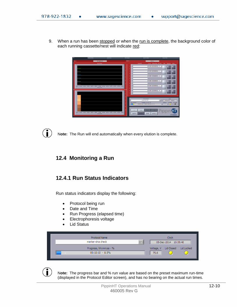
9. When a run has been stopped or when the run is complete, the background color of each running cassette/nest will indicate red:
Note: The Run will end automatically when every elution is complete.
12.4 Monitoring a Run
12.4.1 Run Status Indicators
Run status indicators display the following:
• Protocol being run
• Date and Time
• Run Progress (elapsed time)
• Electrophoresis voltage
• Lid Status
Note: The progress bar and % run value are based on the preset maximum run-time (displayed in the Protocol Editor screen), and has no bearing on the actual run times.
● ●
PippinHT Operations Manual 12-11 460005 Rev G
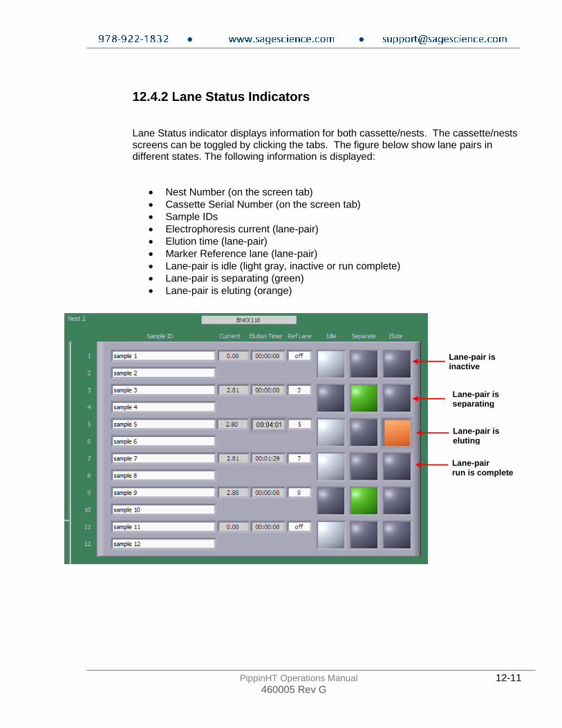
12.4.2 Lane Status Indicators
Lane Status indicator displays information for both cassette/nests. The cassette/nests screens can be toggled by clicking the tabs. The figure below show lane pairs in different states. The following information is displayed:
• Nest Number (on the screen tab)
• Cassette Serial Number (on the screen tab)
• Sample IDs
• Electrophoresis current (lane-pair)
• Elution time (lane-pair)
• Marker Reference lane (lane-pair)
• Lane-pair is idle (light gray, inactive or run complete)
• Lane-pair is separating (green)
• Lane-pair is eluting (orange)
Lane-pair is inactive
Lane-pair is separating
Lane-pair is eluting
Lane-pair run is complete

● ●
PippinHT Operations Manual 12-12 460005 Rev G
12.4.3 Marker Detection Failure Alert
The PippinHT has will run a fail-safe routine if a marker is not detected within the expected time window. Each cassette definition includes a time value by within which all peaks should be called. If the run reaches that specified duration, and the peaks have not been detected, the software decreases the base-to-threshold value by 25% and re-scans for peaks. It will repeat this with an additional 25% decrease in base-to-threshold if peaks are still not detected. If peaks are finally detected, the run will proceed as usual. If peaks are not detected, the lane will switch to 'idle'. This will prevent sample loss. Users can then choose to manually elute their sample from that lane once the run is complete (see section 12.5 for the manual procedure).
The unaffected lanes will proceed to completion.
Internal Standards not detected In lane 1
Red display indicates lanes detection failure. Lanes 1 and 2 are paused.
Unaffected lanes continue until completion.

● ●
PippinHT Operations Manual 12-13 460005 Rev G
12.4.4 Optical Monitoring
Optical monitoring is provided for both cassette/nests. The cassette/nests screens can be toggled by clicking the tabs. There are two monitoring views for each nest; and electropherogram view, and an image view. If a fluorescent marker is detected, a correctly identified marker will have a blue line through the peak.
Important! Fail-Safe for Missed Peak Detection: Each cassette definition includes a time value by within which all peaks should be called. If the run reaches that specified duration, and the peaks have not been detected, the software decreases the base-to-threshold value by 25% and re-scans for peaks. It will repeat this with an additional 25% decrease in base-to-threshold if peaks are still not detected. If peaks are finally detected, the run will proceed as usual. If peaks are still not detected, the lane will switch to 'idle'. This will prevent sample loss. All others lanes will proceed with the run. Users can then choose to manually elute their sample from that lane once the run is complete (see next section, 12.5 for the manual procedure).
Correctly called peaks with be marked with blue lines and the marker size numbers.
● ●
PippinHT Operations Manual 12-14 460005 Rev G
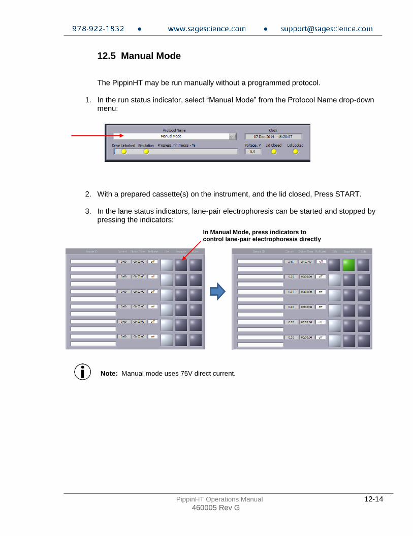
12.5 Manual Mode
The PippinHT may be run manually without a programmed protocol.
1. In the run status indicator, select “Manual Mode” from the Protocol Name drop-down menu:
2. With a prepared cassette(s) on the instrument, and the lid closed, Press START.
3. In the lane status indicators, lane-pair electrophoresis can be started and stopped by pressing the indicators:
Note: Manual mode uses 75V direct current.
In Manual Mode, press indicators to control lane-pair electrophoresis directly

● ●
PippinHT Operations Manual 13-1 460005 Rev G
13 Log Review
The default screen on the PippinHT has a tabbed format. The Log Review is the third tab.
13.1 Overview The Log Review tab is the screen with which users can open saved log files and review the run data that was saved.
Log Review tab
Cassette review tabs
Run parameters
Log File selection
View tools
Cassette Review view
Cassette process view
Cassette process tabs

● ●
PippinHT Operations Manual 13-2 460005 Rev G
13.2 Loading a file
1. Press the folder icon in the Log File window, or press LAST to load the file from the latest run on the PippinHT.
2. If the folder icon is pressed, a pop-up window will launch showing a Windows view of file tree. The directory path is: C:\Users\Public\Documents\Sage Science\PippinHT\Logs\[latest folder]

● ●
PippinHT Operations Manual 14-1 460005 Rev G
14 Managing Files
The default screen on the PippinHT is a tabbed format. The File Manager Tab is the fourth tab.
14.1 Overview The File Manager Tab allows users to access, copy, and delete PippinHT files. There are three types of files used by the system; log (text and image), protocol and cassette type. The screen is divided into two sub-screens; the Pippin file directory on the left, and a target directory (portable “flash” media, i.e. USB key) on the right.
PippinHT File Directory
PippinHT Files
Destination Drive File Directory
Destination Drive Files
File Directory Selection
File Management Commands
File Manager Tab

● ●
PippinHT Operations Manual 14-2 460005 Rev G
14.2 File Types There are three types of directories that host files on the PippinHT. These can be accessed in the lower right hand corner of the File Management Screen:
The file types are: Log Files:
• Optical Calibration -- at the end of every optical calibration routine, a screenshot of the result is saved as a .png file.
• Continuity Test – at the end of every continuity test, a screenshot of the result is saved as a .png file.
• Main Screen – at the end of every run, or if a run is stopped, a screenshot of the main screen is saved as a .png file.
• Run Log – at the end of every run, or if a run is stopped, a text (.txt) file is saved. This files contains optical data, electrical current data, and protocol and sample information from a run. Run Log data may be viewed in the Log Review screen (See Section 12).
Protocol Files: Size selection protocols that have been created by, named, and saved by PippinHT users. These have a .phprot file extension, and are only recognized by the PippinHT.
Cassette Files:
Cassette definition files. These are created by Sage Science and not editable by PippinHT users. These have a .phcass file extension, and are added to the PippinHT during manufacture or through software upgrades.
Note. The PippinHT is equipped with 25 GB of storage. The combined files sizes for the log files saved for each run is about 150 kb, or a total storage capacity for 166,000 runs.

● ●
PippinHT Operations Manual 14-3 460005 Rev G
14.3 Transferring files
Files may be copied between the PippinHT and a USB flash drive. To transfer a file, place a USB drive into the USB port on the front panel of the instrument (the USB ports on the back panel may be used as well). To transfer from the PippinHT to a USB Drive: 1. Select the directory from which the file will be copied. 2. Highlight the file to be copied from the PippinHT. 3. Press the “COPY TO FLASH” button. 4. Press the “EJECT FLASH” button.
5. Remove the USB drive from the USB port.

● ●
PippinHT Operations Manual 14-4 460005 Rev G
To transfer from a USB Drive to the PippinHT: 1. Highlight the file to be copied. 2. Select the directory from which the file will be copied. 3. Press the “COPY TO PIPPIN” button. 4. Press the “EJECT FLASH” button.
5. Remove the USB drive from the USB port.
● ●
PippinHT Operations Manual 15-1 460005 Rev G
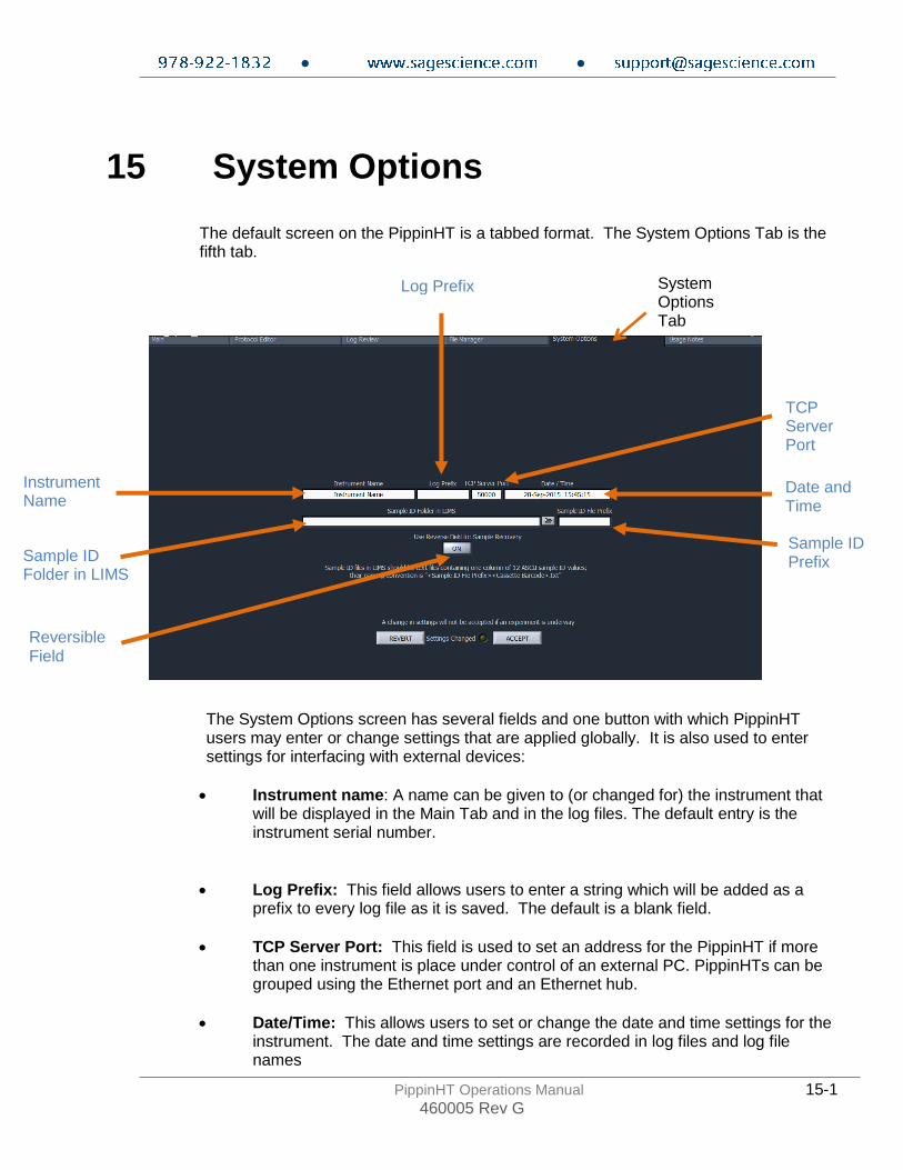
15 System Options
The default screen on the PippinHT is a tabbed format. The System Options Tab is the fifth tab.
The System Options screen has several fields and one button with which PippinHT users may enter or change settings that are applied globally. It is also used to enter settings for interfacing with external devices:
• Instrument name: A name can be given to (or changed for) the instrument that will be displayed in the Main Tab and in the log files. The default entry is the instrument serial number.
• Log Prefix: This field allows users to enter a string which will be added as a prefix to every log file as it is saved. The default is a blank field.
• TCP Server Port: This field is used to set an address for the PippinHT if more than one instrument is place under control of an external PC. PippinHTs can be grouped using the Ethernet port and an Ethernet hub.
• Date/Time: This allows users to set or change the date and time settings for the instrument. The date and time settings are recorded in log files and log file names
System Options Tab
Instrument Name
Log Prefix
Date and Time
Sample ID Folder in LIMS
TCP Server Port
Sample ID Prefix
Reversible Field
● ●
PippinHT Operations Manual 15-2 460005 Rev G
• Sample ID folder in LIMS: This field is used to enter an address on a remote server onto which log files can be exported when using a LIMS system.
• Sample ID Prefix: This field allows users to enter a string which will be added as a prefix to every sample name that is entered. The default is a blank field.
• Reversible Field for Sample Recovery: When activated, all sample collections will terminate with a 5 second field reversal to improve recovery. When deactivated, all sample collections will not include the field reversal. The default setting is off. When activated, the current will be reversed on all subsequent runs until the user changes the setting through the System Options tab.
Note: Users should contact Sage Science for detailed protocols for group control of PippinHTs and/or LIMS integration.

● ●
PippinHT Operations Manual 16-3 460005 Rev G
16 Upgrading PippinHT Software
Pippin upgrade software is available for download at www.sagescience.com/support/. The files are provided in a zip file, and the contents must be extracted to the root directory of a USB flash drive.
16.1 Extracting the Files to a USB flash drive
1. Download the Software Upgrade package by pressing the appropriate link on www.sagescience.com/support (PippinHT “Software Downloads”).
2. Press “Save File” when prompted. The zip file will likely save to a “Downloads” folder on your computer. The file will be named [version number]-HT-[cassette definition (CD) list number]-[release date].zip. (example: v1.04-HT-CD4- 062615.zip)
3. Copy the zip file to a USB drive. Make sure the file is transferred onto the root directory and not placed within a folder.
4. Right-click on the zip file, and select “Extract All”:

● ●
PippinHT Operations Manual 16-4 460005 Rev G
5. A window will launch to prompt you to select a destination where to extract files. The prompt may suggest creating folder based on the zip file name. If necessary, delete this and make sure that only the root directory appears (in the sample below, E:\ is the root directory of the USB drive).
6. The final USB file structure should be as shown. The zip file may be deleted.
16.2 Upgrading the Pippin Instrument Software
1. Insert the USB drive with the upgrade folder into the USB port on the front
panel of PippinHT instrument. 2. From the Main Tab, click on the PippinHT logo. This will launch the
information window.
● ●
PippinHT Operations Manual 16-5 460005 Rev G
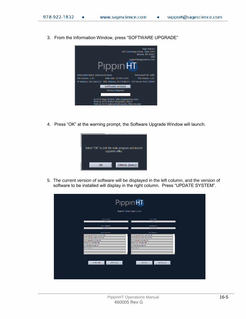
3. From the Information Window, press “SOFTWARE UPGRADE”
4. Press “OK” at the warning prompt, the Software Upgrade Window will launch.
5. The current version of software will be displayed in the left column, and the version of software to be installed will display in the right column. Press “UPDATE SYSTEM”.
● ●
PippinHT Operations Manual 16-6 460005 Rev G
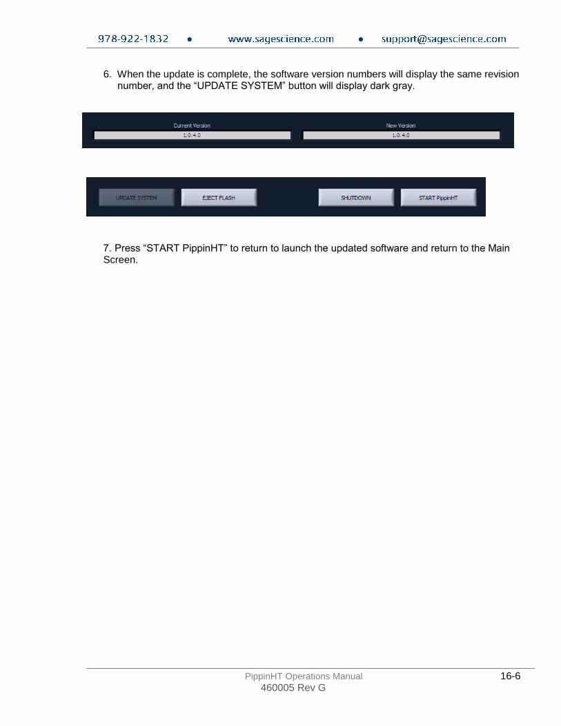
6. When the update is complete, the software version numbers will display the same revision number, and the “UPDATE SYSTEM” button will display dark gray. 7. Press “START PippinHT” to return to launch the updated software and return to the Main Screen.
● ●
PippinHT Operations Manual 17-7 460005 Rev G
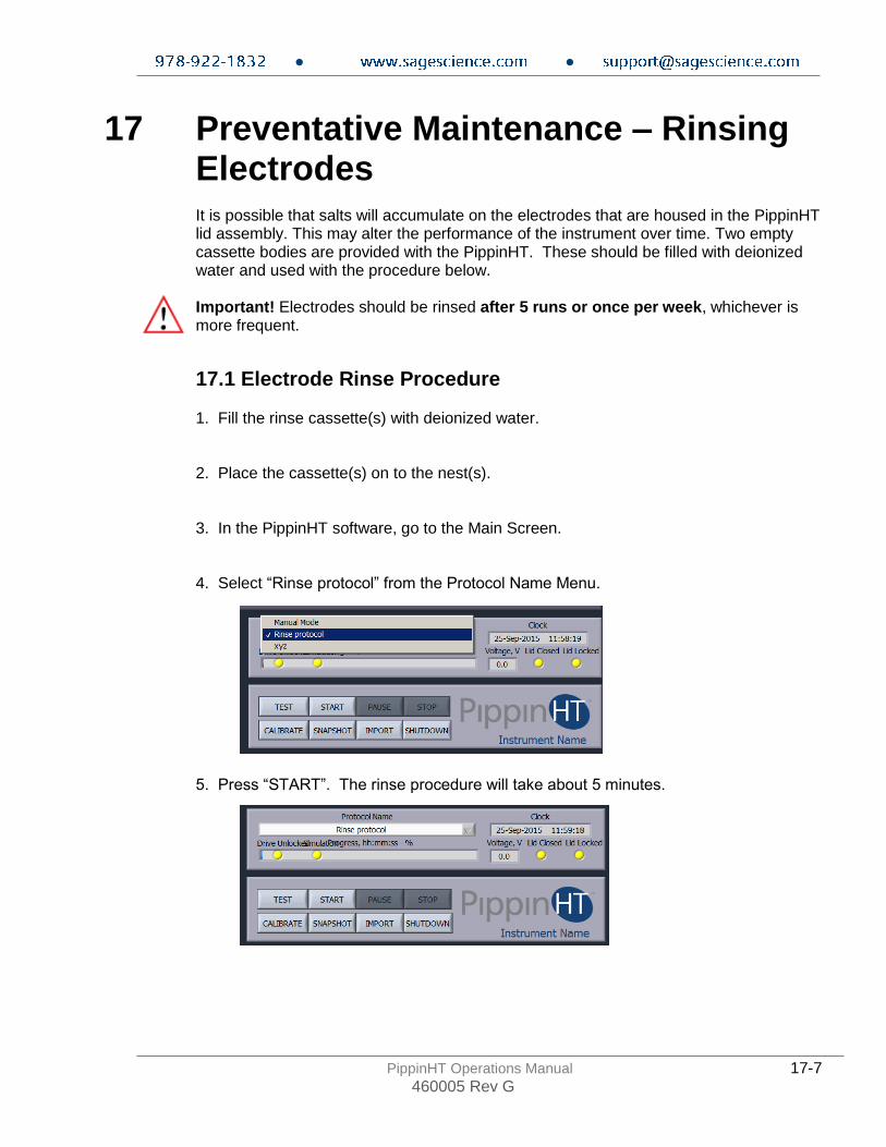
17 Preventative Maintenance – Rinsing Electrodes It is possible that salts will accumulate on the electrodes that are housed in the PippinHT lid assembly. This may alter the performance of the instrument over time. Two empty cassette bodies are provided with the PippinHT. These should be filled with deionized water and used with the procedure below. Important! Electrodes should be rinsed after 5 runs or once per week, whichever is more frequent.
17.1 Electrode Rinse Procedure 1. Fill the rinse cassette(s) with deionized water. 2. Place the cassette(s) on to the nest(s). 3. In the PippinHT software, go to the Main Screen. 4. Select “Rinse protocol” from the Protocol Name Menu.
5. Press “START”. The rinse procedure will take about 5 minutes.

● ●
PippinHT Operations Manual 18-1 460005 Rev G
18 Warranty and Service
Warranty Sage Science will offer a no charge repair or replacement of defective product if notified within the warranty period and product has not been misused, altered or damaged by disaster. This warranty is not transferable from the original purchaser to a subsequent purchaser. Instruments – The PippinHT instrument and monitor have a standard 1-year parts and labor warranty. Instruments are subject to depot repair or replacement. On-site maintenance or repair is not implied. Do not attempt to repair or disassemble the PippinHT instrument. This will void the remaining warranty and possibly create a dangerous condition. Sage Science support staff may ask for a log file or image file to evaluate or troubleshoot instrument issues. High Voltage! The PippinHT contains high voltage apparatus. The instrument should be repaired by authorized personnel only. Do not disassemble under any circumstance.
Cassettes – Cassettes have a 18-month warranty. If a cassette or sample lane is defective Sage Science will replace the cassette at no cost. The defective cassette should be disposed of as per regulations at the user’s facility. Sage Science support staff may ask for a log file or image file to evaluate or troubleshoot cassette issues. Cassette Disposal Reagents and buffer should be disposed of according to internal lab safety policy. Cassettes should be disposed of as laboratory waste.
Note: Internal standards use fluorescein dye.

● ●
PippinHT Operations Manual 19-1 460005 Rev G
19 Instrument Specifications
Specifications for PippinHT Instrument
Electrophoresis Voltage up to 100V, constant or pulsed
Optical detection 470 nm excitation, 525 nm emission
Power Requirements 100-240 VAC +/-10% VAC, 2.5 A, 50-60 Hz
Weight 20 lbs / 9 kg
Dimensions
• Closed Position: 13”W x 10.5”H x 10”D (33 x 27 x 25 cm)
• Open Position: 13”W x 18”H x 17” D (33 x 46 x 43 cm)
Approvals
Country of Origin United States
● ●
PippinHT Operations Manual 20-1 460005 Rev G
20 Gel Cassettes Specifications
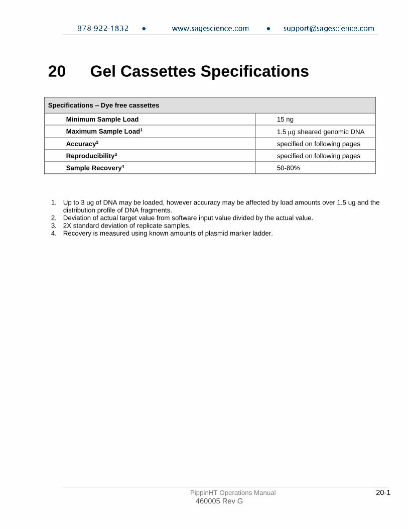
Specifications – Dye free cassettes
Minimum Sample Load 15 ng
Maximum Sample Load1 1.5 g sheared genomic DNA
Accuracy2 specified on following pages
Reproducibility3 specified on following pages
Sample Recovery4 50-80%
1. Up to 3 ug of DNA may be loaded, however accuracy may be affected by load amounts over 1.5 ug and the distribution profile of DNA fragments.
2. Deviation of actual target value from software input value divided by the actual value. 3. 2X standard deviation of replicate samples. 4. Recovery is measured using known amounts of plasmid marker ladder.
● ●
PippinHT Operations Manual 20-2 460005 Rev G
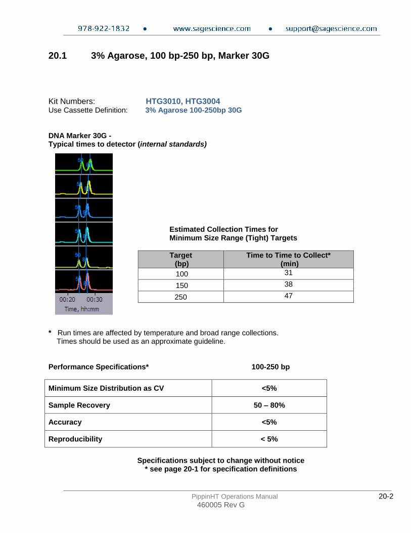
20.1 3% Agarose, 100 bp-250 bp, Marker 30G
Kit Numbers: HTG3010, HTG3004 Use Cassette Definition: 3% Agarose 100-250bp 30G DNA Marker 30G - Typical times to detector (internal standards)
Estimated Collection Times for Minimum Size Range (Tight) Targets
Target (bp)
Time to Time to Collect* (min)
100 31
150 38
250 47
* Run times are affected by temperature and broad range collections. Times should be used as an approximate guideline. Performance Specifications* 100-250 bp
Minimum Size Distribution as CV <5%
Sample Recovery 50 – 80%
Accuracy <5%
Reproducibility < 5%
Specifications subject to change without notice
* see page 20-1 for specification definitions

● ●
PippinHT Operations Manual 20-3 460005 Rev G
20.2 2% Agarose, 100 bp-600 bp, Marker 20B
Kit Numbers: HTC2010, HTC2004 Use Cassette Definition: 2% Agarose 100-600bp 20B DNA Marker 20B - Typical times to detector(internal standards)
Estimated Collection Times for Minimum Size Range (Tight) Targets
Target (bp)
Time to Time to Collect* (min)
100 25
200 28
300 32
400 36
500 40
600 45
* Run times are affected by temperature and broad range collections. Times should be used as an approximate guideline. Performance Specifications* 100-600 bp
Minimum Size Distribution as CV <8%
Sample Recovery 50 – 80%
Accuracy <5%
Reproducibility < 5%
Specifications subject to change without notice
* see page 20-1 for specification definitions

● ●
PippinHT Operations Manual 20-4 460005 Rev G
20.3 1.5% Agarose, 250 bp-1.5 kb, Marker 15C
Kit Numbers: HTC1510, HTC1504 Use Cassette Definition: 1.5% Agarose 250bp-1.5kb 15C DNA Marker 15C - Typical times to detector (internal standards)
Estimated Collection Times for Minimum Size Range (Tight) Targets
Target (bp)
Time to Time to Collect* (min)
500 32
800 37
1100 40
1400 45
* Run times are affected by temperature and broad range collections. Times should be used as an approximate guideline. Performance Specifications* 250-1500 bp
Minimum Size Distribution as CV <8%
Sample Recovery 50 – 80%
Accuracy <5%
Reproducibility < 5%
Specifications subject to change without notice
* see page 20-1 for specification definitions

● ●
PippinHT Operations Manual 20-5 460005 Rev G
25.4 1.5% Agarose, High-Pass, >300bp-1.5kb, Marker 15C
Use Product Number: HTC1510 Use Cassette Definition: 1.5% Agarose 300-1500bp High-Pass Marker 15C DNA Marker 15C - Typical times to detector (internal standards)
High Pass Threshold
(bp)
Time to Time to Collect*
(hr:min)
500 1:20
1000 1:30
1500 1:40
2000 1:55
Performance Specifications*
Accuracy, “BPStart” <10%
Reproducibility, “BPStart” < 10%
Specifications subject to change without notice
* see page 25-1 for specification definitions
Collects fragments up to 5- 8kb

● ●
PippinHT Operations Manual 20-6 460005 Rev G
20.5 0.75% Agarose, High-Pass >6-10 kb, Marker 75D
Kit Numbers: HPD7510, HPD7504 Use Cassette Definition: 0.75% Agarose 6-10kb high-pass 75D DNA Marker 75D - Typical times to detector (external marker)
Estimated Collection Times for Minimum Size Range (Tight) Targets
High Pass Threshold
(bp)
Time to Time to Collect* (min)
6000 63
7000 67
8000 70
9000 74
* Run times are affected by ambient temperature. Times should be used as an approximate guideline. Performance Specifications* >6000-10000 bp
Minimum Size Distribution as CV N/A
Sample Recovery 50 – 80%
Start Value Accuracy <10%
Start Value Reproducibility < 10%
Specifications subject to change without notice
* see page 20-1 for specification definitions
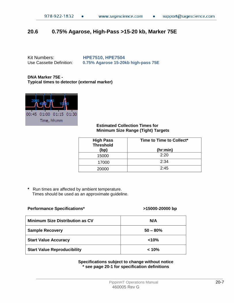
● ●
PippinHT Operations Manual 20-7 460005 Rev G
20.6 0.75% Agarose, High-Pass >15-20 kb, Marker 75E
Kit Numbers: HPE7510, HPE7504 Use Cassette Definition: 0.75% Agarose 15-20kb high-pass 75E DNA Marker 75E - Typical times to detector (external marker)
Estimated Collection Times for Minimum Size Range (Tight) Targets
High Pass Threshold
(bp)
Time to Time to Collect*
(hr:min)
15000 2:20
17000 2:34
20000 2:45
* Run times are affected by ambient temperature. Times should be used as an approximate guideline. Performance Specifications* >15000-20000 bp
Minimum Size Distribution as CV N/A
Sample Recovery 50 – 80%
Start Value Accuracy <10%
Start Value Reproducibility < 10%
Specifications subject to change without notice
* see page 20-1 for specification definitions
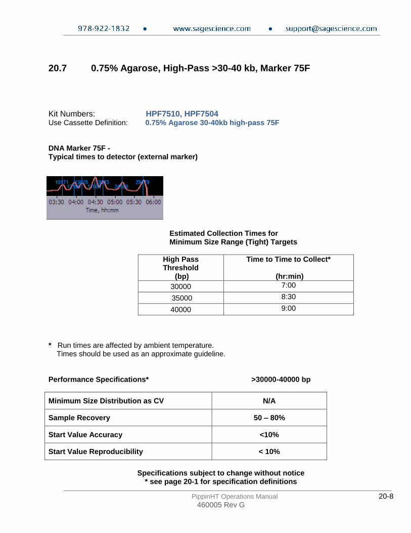
● ●
PippinHT Operations Manual 20-8 460005 Rev G
20.7 0.75% Agarose, High-Pass >30-40 kb, Marker 75F
Kit Numbers: HPF7510, HPF7504 Use Cassette Definition: 0.75% Agarose 30-40kb high-pass 75F DNA Marker 75F - Typical times to detector (external marker)
Estimated Collection Times for Minimum Size Range (Tight) Targets
High Pass Threshold
(bp)
Time to Time to Collect*
(hr:min)
30000 7:00
35000 8:30
40000 9:00
* Run times are affected by ambient temperature. Times should be used as an approximate guideline. Performance Specifications* >30000-40000 bp
Minimum Size Distribution as CV N/A
Sample Recovery 50 – 80%
Start Value Accuracy <10%
Start Value Reproducibility < 10%
Specifications subject to change without notice
* see page 20-1 for specification definitions

● ●
PippinHT Operations Manual 20-9 460005 Rev G
500 Cummings Center Suite 2400 Beverly, MA 01915