Dmx512-A Guide (8x10) Esta
112
Recommended Practice for DMX512 2nd Edition Incorporating USITT DMX512-A and Remote Device Management - RDM A guide for users and installers By Adam Bennette
-
Upload
arturo-sierra -
Category
Documents
-
view
367 -
download
59
Transcript of Dmx512-A Guide (8x10) Esta
Recommended Practice forDMX512
2nd Edition
Incorporating USITT DMX512-A and
Remote Device Management - RDM
A guide for usersand installers
By Adam Bennette
Recommended Practice forDMX512
2nd Edition incorporating USITT DMX512-A and
Remote Device Management - RDM
1st Edition: © PLASA 1994Reprinted 2000, 2006
2nd Edition: © PLASA 2008Reprinted 2012
This document is protected by copyright. The copyright prohibits the use of any part of this document for commercial
documentation, sales material or other commercial purposes without the express writtenconsent of PLASA.
2nd Edition Copyright © PLASA 2008
All rights reserved
ISBN: 978-0-9557035-2-2
2 Recommended Practice for DMX512 - 2nd Edition ©PLASA, 2008
Disclaimer:
All the information in this document has been carefully checked;
however, no liability is assumed for any loss or damage caused by
the use or misuse of any of the information contained herein.
No information of a manufacturer or product specific nature has
been included and no endorsement or criticism of specific products
is implied or intended.
This document has been endorsed by PLASA and USITT without
regard to whether or not the information contained herein may
involve patents on materials, articles or processes. By such
endorsement, PLASA, USITT and the author do not assume any
liability to any patent owner, nor do they assume any liability
whatsoever to parties adopting the ANSI E1.11-2008 (USITT
DMX512-A) or ANSI E1.20-2010 (RDM) Standards or the
Recommended Practice described herein.
3Recommended Practice for DMX512 - 2nd Edition©PLASA, 2008
The author:
Adam Bennette started in the
entertainment industry building pipe
organs with electronic guts. He then
moved into the field of electronic
instruments and soon found himself on
tour with Rock bands. After touring
around the US and Europe for a number of years he settled down to
the design of lighting equipment, consoles and dimmers in
particular.
Adam has been involved in the design of DMX512 based products
since their first introduction in 1986. Adam set-up his own business,
A.B. Micro, making DMX512 testing equipment for engineers.
At present he is the Technical Director of Electronic Theatre Controls
Ltd. in London.
4 Recommended Practice for DMX512 - 2nd Edition ©PLASA, 2008
Acknowledgements
Much of this new edition is based on the first edition ‘Recommended Practice
for DMX512’ which was published in 1994 and was reviewed at that time by
a team of industry colleagues. Their original comments and input are still
pertinent in most cases and I am still grateful for their help with the original
version, they are:
In addition I also acknowledge valuable contributions to the new edition from:
Special thanks to Ron Bonner of PLASA and Mitch Hefter of USITT for their
efforts in managing the production of this booklet.
This booklet is dedicated to the memory of Tony Gottelier who gave me so
much support and encouragement with the first edition.
Adam Bennette, London, 2008
Bill Florac, USA
Bob Goddard, USA
Gary Pritchard, Australia
Mike Hayward, UK
Peter Brooks, UK
Philip Nye, UK
Ralph Weber, USA
Richard Salzedo, UK
Richard Thornton-Brown, UK
Steve Carlson, USA
Steve Terry, USA
Dave Higgins, Canada
David North, USA
Doug Fleenor, USA
John Sondericker, USA
Mitch Hefter, USA
Peter Willis, UK
Wayne Howell, UK
5Recommended Practice for DMX512 - 2nd Edition©PLASA, 2008
Contents
How to use this document . . . . . . . . . . . . . . . . . . . . . . . . . . . . . . . . . . . . . . . . . . . 8
About the 2nd Edition . . . . . . . . . . . . . . . . . . . . . . . . . . . . . . . . . . . . . . . . . . . . . . . 9
DMX512-A protocol . . . . . . . . . . . . . . . . . . . . . . . . . . . . . . . . . . . . . . . . . . . . . . . 10Previous version of DMX512 specification . . . . . . . . . . . . . . . . . . . . . . . . . . 10Development of DMX512-A . . . . . . . . . . . . . . . . . . . . . . . . . . . . . . . . . . . . . . 11Remote Device Management (RDM) . . . . . . . . . . . . . . . . . . . . . . . . . . . . . . . 11Other enhancements in DMX512-A . . . . . . . . . . . . . . . . . . . . . . . . . . . . . . . . 12
Cables . . . . . . . . . . . . . . . . . . . . . . . . . . . . . . . . . . . . . . . . . . . . . . . . . . . . . . . . . . 13
Cable types . . . . . . . . . . . . . . . . . . . . . . . . . . . . . . . . . . . . . . . . . . . . . . . . . . . . . . 14Using Ethernet cables (Cat5, Cat5e, Cat6) . . . . . . . . . . . . . . . . . . . . . . . . . . . 15
Rules for using Ethernet cables: . . . . . . . . . . . . . . . . . . . . . . . . . . . . . . . . . 15Recommended minimum cable gauges . . . . . . . . . . . . . . . . . . . . . . . . . . . . 16
Connections. . . . . . . . . . . . . . . . . . . . . . . . . . . . . . . . . . . . . . . . . . . . . . . . . . . . . . 18XLR Connectors . . . . . . . . . . . . . . . . . . . . . . . . . . . . . . . . . . . . . . . . . . . . . . . . 18RJ45 (Ethernet) connectors. . . . . . . . . . . . . . . . . . . . . . . . . . . . . . . . . . . . . . . 19RJ45 wiring code. . . . . . . . . . . . . . . . . . . . . . . . . . . . . . . . . . . . . . . . . . . . . . . 19Compatibility of RJ45 connectors. . . . . . . . . . . . . . . . . . . . . . . . . . . . . . . . . . 20
Termination . . . . . . . . . . . . . . . . . . . . . . . . . . . . . . . . . . . . . . . . . . . . . . . . . . . . . . 21Line biasing . . . . . . . . . . . . . . . . . . . . . . . . . . . . . . . . . . . . . . . . . . . . . . . . . . . 23Mixed RDM and non-RDM systems . . . . . . . . . . . . . . . . . . . . . . . . . . . . . . . . 25Using RDM with devices that do not check the Start code . . . . . . . . . . . . . 26Mixing RDM and non-RDM devices downstream of splitters. . . . . . . . . . . . 26
DMX512-A Networks. . . . . . . . . . . . . . . . . . . . . . . . . . . . . . . . . . . . . . . . . . . . . . . 27Simple splitter cables (‘Y’ leads). . . . . . . . . . . . . . . . . . . . . . . . . . . . . . . . . . . 28
Repeater and Splitter / Distribution amplifiers . . . . . . . . . . . . . . . . . . . . . . . . . . 29Simple Repeaters (non RDM capable) . . . . . . . . . . . . . . . . . . . . . . . . . . . . . . 29RDM bi-directional Repeater amplifiers . . . . . . . . . . . . . . . . . . . . . . . . . . . . . 30Built-in repeaters . . . . . . . . . . . . . . . . . . . . . . . . . . . . . . . . . . . . . . . . . . . . . . . 30Splitters . . . . . . . . . . . . . . . . . . . . . . . . . . . . . . . . . . . . . . . . . . . . . . . . . . . . . . 31Connection of pins 4 & 5 . . . . . . . . . . . . . . . . . . . . . . . . . . . . . . . . . . . . . . . . . 31
Network Isolation . . . . . . . . . . . . . . . . . . . . . . . . . . . . . . . . . . . . . . . . . . . . . . . . . 33Grounding . . . . . . . . . . . . . . . . . . . . . . . . . . . . . . . . . . . . . . . . . . . . . . . . . . . . 33Data errors caused by poor grounding . . . . . . . . . . . . . . . . . . . . . . . . . . . . . 34Safety problems caused by poor grounding . . . . . . . . . . . . . . . . . . . . . . . . . 34Optical-isolators for proper grounding. . . . . . . . . . . . . . . . . . . . . . . . . . . . . . 35Opto-isolation in RDM systems . . . . . . . . . . . . . . . . . . . . . . . . . . . . . . . . . . . 36
6 Recommended Practice for DMX512 - 2nd Edition ©PLASA, 2008
Direct-on-line opto-isolation . . . . . . . . . . . . . . . . . . . . . . . . . . . . . . . . . . . . . . 36Opto-isolated Repeaters and Splitters . . . . . . . . . . . . . . . . . . . . . . . . . . . . . . 37European Electromagnetic Compatibility (EMC) . . . . . . . . . . . . . . . . . . . . . . 37Radio Interference Suppression . . . . . . . . . . . . . . . . . . . . . . . . . . . . . . . . . . . 39Totally isolated systems . . . . . . . . . . . . . . . . . . . . . . . . . . . . . . . . . . . . . . . . . 39
In-line DMX processing equipment . . . . . . . . . . . . . . . . . . . . . . . . . . . . . . . . . . . 41Patching Computers . . . . . . . . . . . . . . . . . . . . . . . . . . . . . . . . . . . . . . . . . . . . 41Merging Computers . . . . . . . . . . . . . . . . . . . . . . . . . . . . . . . . . . . . . . . . . . . . 42RDM and in-line processing devices . . . . . . . . . . . . . . . . . . . . . . . . . . . . . . . 43In-Line Backup Computers . . . . . . . . . . . . . . . . . . . . . . . . . . . . . . . . . . . . . . . 43Processing delays . . . . . . . . . . . . . . . . . . . . . . . . . . . . . . . . . . . . . . . . . . . . . . 44RDM processing delays. . . . . . . . . . . . . . . . . . . . . . . . . . . . . . . . . . . . . . . . . . 46Analog Converters. . . . . . . . . . . . . . . . . . . . . . . . . . . . . . . . . . . . . . . . . . . . . . 46
Tips for users of analog converters . . . . . . . . . . . . . . . . . . . . . . . . . . . . . . 48Protocol Converters. . . . . . . . . . . . . . . . . . . . . . . . . . . . . . . . . . . . . . . . . . . . . 48
DMX bulk transport systems . . . . . . . . . . . . . . . . . . . . . . . . . . . . . . . . . . . . . . . . 49DMX transport via Ethernet . . . . . . . . . . . . . . . . . . . . . . . . . . . . . . . . . . . . . . 49
DMX produced by an Ethernet node . . . . . . . . . . . . . . . . . . . . . . . . . . . . . 50DMX transport via wireless link . . . . . . . . . . . . . . . . . . . . . . . . . . . . . . . . . . . 51RDM via wireless link . . . . . . . . . . . . . . . . . . . . . . . . . . . . . . . . . . . . . . . . . . . 52
Address settings . . . . . . . . . . . . . . . . . . . . . . . . . . . . . . . . . . . . . . . . . . . . . . . . . . 53Digit display & keys . . . . . . . . . . . . . . . . . . . . . . . . . . . . . . . . . . . . . . . . . . . . . 53Thumbwheel switches . . . . . . . . . . . . . . . . . . . . . . . . . . . . . . . . . . . . . . . . . . 53DIP switches. . . . . . . . . . . . . . . . . . . . . . . . . . . . . . . . . . . . . . . . . . . . . . . . . . . 54Address offsets for multiple DMX512 lines . . . . . . . . . . . . . . . . . . . . . . . . . . 56
RDM functions . . . . . . . . . . . . . . . . . . . . . . . . . . . . . . . . . . . . . . . . . . . . . . . . . . . . 58RDM overview . . . . . . . . . . . . . . . . . . . . . . . . . . . . . . . . . . . . . . . . . . . . . . . . . 58RDM addressing process . . . . . . . . . . . . . . . . . . . . . . . . . . . . . . . . . . . . . . . . 59Discovery . . . . . . . . . . . . . . . . . . . . . . . . . . . . . . . . . . . . . . . . . . . . . . . . . . . . . 59RDM Messaging. . . . . . . . . . . . . . . . . . . . . . . . . . . . . . . . . . . . . . . . . . . . . . . . 60Device identification . . . . . . . . . . . . . . . . . . . . . . . . . . . . . . . . . . . . . . . . . . . . 61Getting and Setting device properties . . . . . . . . . . . . . . . . . . . . . . . . . . . . . . 61RDM message types . . . . . . . . . . . . . . . . . . . . . . . . . . . . . . . . . . . . . . . . . . . . 62
Fault Finding . . . . . . . . . . . . . . . . . . . . . . . . . . . . . . . . . . . . . . . . . . . . . . . . . . . . . 63Voltage Tests . . . . . . . . . . . . . . . . . . . . . . . . . . . . . . . . . . . . . . . . . . . . . . . . . . 63Common-mode voltage tests . . . . . . . . . . . . . . . . . . . . . . . . . . . . . . . . . . . . . 64Resistance tests . . . . . . . . . . . . . . . . . . . . . . . . . . . . . . . . . . . . . . . . . . . . . . . . 65Oscilloscope tests . . . . . . . . . . . . . . . . . . . . . . . . . . . . . . . . . . . . . . . . . . . . . . 65Specialised DMX512 test equipment . . . . . . . . . . . . . . . . . . . . . . . . . . . . . . . 66Fault Finding Checklist. . . . . . . . . . . . . . . . . . . . . . . . . . . . . . . . . . . . . . . . . . . 67
7Recommended Practice for DMX512 - 2nd Edition©PLASA, 2008
The EIA-485 (RS-485) communications spec. . . . . . . . . . . . . . . . . . . . . . . . . . . . 68EIA-485 voltages . . . . . . . . . . . . . . . . . . . . . . . . . . . . . . . . . . . . . . . . . . . . . . . 69
Typical voltages found on a EIA-485 cable: . . . . . . . . . . . . . . . . . . . . . . . . 69Allowable extremes for EIA-485 voltages: . . . . . . . . . . . . . . . . . . . . . . . . . 70
Bits & Bytes . . . . . . . . . . . . . . . . . . . . . . . . . . . . . . . . . . . . . . . . . . . . . . . . . . . . . . 71
The DMX512 packet . . . . . . . . . . . . . . . . . . . . . . . . . . . . . . . . . . . . . . . . . . . . . . . 73Regular DMX512 ‘levels only’ packet. . . . . . . . . . . . . . . . . . . . . . . . . . . . . . . 73Refresh rate . . . . . . . . . . . . . . . . . . . . . . . . . . . . . . . . . . . . . . . . . . . . . . . . . . . 75Continuous refresh . . . . . . . . . . . . . . . . . . . . . . . . . . . . . . . . . . . . . . . . . . . . . 75
Transmitted maximum length packet: . . . . . . . . . . . . . . . . . . . . . . . . . . . . 76Transmitted minimum length packet: . . . . . . . . . . . . . . . . . . . . . . . . . . . . . 76Receiver timing requirements: . . . . . . . . . . . . . . . . . . . . . . . . . . . . . . . . . . 77
RDM packet structure . . . . . . . . . . . . . . . . . . . . . . . . . . . . . . . . . . . . . . . . . . . 77
Signal timings . . . . . . . . . . . . . . . . . . . . . . . . . . . . . . . . . . . . . . . . . . . . . . . . . . . . 78Break timing . . . . . . . . . . . . . . . . . . . . . . . . . . . . . . . . . . . . . . . . . . . . . . . . . . . 79Mark-after-Break timing . . . . . . . . . . . . . . . . . . . . . . . . . . . . . . . . . . . . . . . . . . 79Inter-slot time / Mark-between-slot time . . . . . . . . . . . . . . . . . . . . . . . . . . . . 80Break-to-Break time . . . . . . . . . . . . . . . . . . . . . . . . . . . . . . . . . . . . . . . . . . . . . 81Loss of data tolerance . . . . . . . . . . . . . . . . . . . . . . . . . . . . . . . . . . . . . . . . . . . 81Summary of DMX512 packet timings . . . . . . . . . . . . . . . . . . . . . . . . . . . . . . 82RDM impact on DMX refresh rate . . . . . . . . . . . . . . . . . . . . . . . . . . . . . . . . . 83
DIP switch codes . . . . . . . . . . . . . . . . . . . . . . . . . . . . . . . . . . . . . . . . . . . . . . . . . . 84
DMX512 ‘universe’ address offsets . . . . . . . . . . . . . . . . . . . . . . . . . . . . . . . . . . . 89
Binary/Hexadecimal/Decimal conversions. . . . . . . . . . . . . . . . . . . . . . . . . . . . . . 94
Glossary of terms . . . . . . . . . . . . . . . . . . . . . . . . . . . . . . . . . . . . . . . . . . . . . . . . . 97
Quick summary . . . . . . . . . . . . . . . . . . . . . . . . . . . . . . . . . . . . . . . . . . . . . . . . . . 102Cable. . . . . . . . . . . . . . . . . . . . . . . . . . . . . . . . . . . . . . . . . . . . . . . . . . . . . . . . 102Connections . . . . . . . . . . . . . . . . . . . . . . . . . . . . . . . . . . . . . . . . . . . . . . . . . . 102
EIA-485 cable: . . . . . . . . . . . . . . . . . . . . . . . . . . . . . . . . . . . . . . . . . . . . . . 102Cat5, 5e or 6 cable (Ethernet cable) in 5 pin XLR. . . . . . . . . . . . . . . . . . . 103Cat5, 5e or 6 cable in IEC60603-7 (RJ45) connector . . . . . . . . . . . . . . . . 103
Termination . . . . . . . . . . . . . . . . . . . . . . . . . . . . . . . . . . . . . . . . . . . . . . . . . . 104DMX512 line routing . . . . . . . . . . . . . . . . . . . . . . . . . . . . . . . . . . . . . . . . . . . 105Physical layout . . . . . . . . . . . . . . . . . . . . . . . . . . . . . . . . . . . . . . . . . . . . . . . . 105Isolation . . . . . . . . . . . . . . . . . . . . . . . . . . . . . . . . . . . . . . . . . . . . . . . . . . . . . 106RDM systems. . . . . . . . . . . . . . . . . . . . . . . . . . . . . . . . . . . . . . . . . . . . . . . . . 107Equipment incompatibility, who is to blame? . . . . . . . . . . . . . . . . . . . . . . . 107
Useful addresses . . . . . . . . . . . . . . . . . . . . . . . . . . . . . . . . . . . . . . . . . . . . . . . . . 109
Recommended reading. . . . . . . . . . . . . . . . . . . . . . . . . . . . . . . . . . . . . . . . . . . . 110
8 Recommended Practice for DMX512 - 2nd Edition ©PLASA, 2008
How to use this document
The purpose of this document is to explain the DMX512-A specification and to
offer examples and professional advice on how to set up a successful
DMX512-A system. While it also offers advice on certain aspects of the design
of actual DMX512-A equipment, it does not necessarily contain all the
information required to design DMX512-A compliant equipment.
This document is a joint PLASA/USITT Recommended Practice, not an ANSI,
USITT or PLASA Standard.
Readers wishing to design DMX512-A compliant equipment must also refer to
the original ANSI E1.11-2008 (USITT DMX512-A), ANSI E1.20-2010 (RDM)
Standards and the EIA-485 (RS-485) standard.
This document does not replace the USITT DMX512 (1990) nor the ANSI
E1.11-2008 (USITT DMX512-A) and ANSI E1.20-2010 (RDM) Standards, and in
all cases where there is any conflict, the ANSI Standards shall apply. The ANSI
Standards are available from the address given on page 109.
If you wish to participate in the ongoing development and maintenance of the
DMX512 standard by PLASA and USITT please contact those organisations
directly. Contact details can be found on page 109.
Nearly all problems encountered by DMX512 users and installers are
due to simple cable faults, poor cable layout or interference. There
are also a few products on the market which do not conform exactly
to the DMX512 specification. Following the advice given in the short
summary on page 102 will ensure correct operation.
9Recommended Practice for DMX512 - 2nd Edition©PLASA, 2008
About the 2nd Edition
The need for a revised 2nd edition of this guide has arisen due to the revision
of the DMX512 specification as well as the publication of a new Standard,
Remote Device Management (RDM). The new specifications add features to the
original DMX512 control protocol. Some of these features require systems to
be set up differently from the previous simpler systems. In places in this
booklet this means that advice is given that is either new or different from the
previous edition.
Users who only require a simple DMX system, without any of the new features,
may still use the original advice in the 1st edition of this booklet if they wish,
however, systems set up in that way may not be upgradeable in the future.
I therefore recommend that all new systems be set up in the way described in
this 2nd edition.
Where new advice is given or where there is now advice that is in contradiction
to the previous methods I have marked these with a line in the margin thus:
2nd Edition Revised Advice.
Warnings or emphasized texts are shown in italic, thus:
Warning or emphasis text.
10 Recommended Practice for DMX512 - 2nd Edition ©PLASA, 2008
DMX512-A protocol
Previous version of DMX512 specification
The DMX512 protocol was first developed in 1986 by a committee of the USITT
(United States Institute for Theater Technology) as a means to control dimmers
from lighting consoles via a standard interface. Before DMX, dimmers were
either controlled via individual wires carrying a control voltage or by various
proprietary digital or multiplexed analog links.
The analog, wire per dimmer, systems were bulky, expensive and non-standard.
They necessitated adapter leads, amplifiers or voltage inverters in order to
interface dimmers of one make with consoles of another make. In addition,
a fault on the cable or connectors was difficult to repair.
The digital systems available before the widespread adoption of DMX512 were
all different and incompatible. Furthermore, manufacturers were reluctant to
reveal exactly how they worked for fear of commercial piracy. This left the
end-user with very few options. If they wanted a certain console they often had
no choice but to use dimmers from the same manufacturer.
DMX512 is not a perfect solution for entertainment control but it is by far the
most widely used. Its original design was deliberately kept simple in order to
persuade the largest number of manufacturers to adopt it. The simple design
was attractive to manufacturers because it reduced the need for large
investments or drastic re-design of their existing products.
The shortcomings of DMX512 have been widely discussed in various trade
forums and some of these issues are dealt with later in this document.
However, most problems found with DMX512 systems result from bad practices
or a lack of understanding about what can and cannot be done with a DMX512
network.
11Recommended Practice for DMX512 - 2nd Edition©PLASA, 2008
Development of DMX512-A
During the 1990s as DMX became the dominant Standard for lighting control it
became apparent to users and manufacturers that several improvements were
desirable. At a meeting at the PLASA trade show in 1994 several proposals
were made to allow the DMX cable to return information from devices or allow
other functions, such as software downloads. Gradually a consensus was
reached on the scope of work necessary and for several years a technical team
under the auspices of ESTA (now PLASA) worked on the task of devising a way
to add features to DMX512 without compromising its main function of level
control in real-time. The result of this effort are the ANSI E1.11-2008 (USITT
DMX512-A) and ANSI E1.20-2010 (RDM) specifications.
Now DMX systems may offer the user the simplest degree of level control
through to a fully interactive control system able to report back from each
device. In particular the new revised specification provides a means to
remotely set the DMX address, thus saving users many trips up ladders to
operate switches on devices.
The revised specification does not change the fundamental way that DMX may
be used to operate dimmers and moving lights or other devices to set levels.
Users with this simpler requirement need not be concerned at all with the
workings of the advanced features.
Remote Device Management (RDM)
The main new feature is Remote Device Management (RDM). Throughout this
booklet the term RDM is used to indicate use of a new feature that operates
bi-directionally.
RDM offers a means to remotely configure and report the status of a device, for
instance, set the DMX address, detect missing dimmer load, lamp failure, fog
fluid low, operating temperature and so on.
12 Recommended Practice for DMX512 - 2nd Edition ©PLASA, 2008
RDM-capable DMX systems have much in common with simpler past DMX
systems but may not function properly, or at all, when used with older DMX
equipment.
RDM capable DMX equipment is backwards compatible with older simple DMX
equipment providing that the older equipment properly implemented the
original DMX512 or DMX512/1990 specifications.
Important note:
RDM capable DMX equipment will function normally, in the same way
as previous DMX equipment, if the RDM features are not activated at
the console or controller. RDM-capable devices cannot send any
RDM information unless they are instructed to do so by the controller
software.
Other enhancements in DMX512-A
The DMX512-A specification also defines several possible uses of the spare
wire pair connected to pins 4 & 5. These features are for possible future
implementation and have been defined so that if they are used, compatibility
can be ensured. Currently none of these possible enhancements have been
implemented in a standardised way. Equipment designers wishing to make use
of these features should read the ANSI E1.11 specification.
These extra wires are now explicitly defined as signalling wires and are
specifically not intended to carry power.
13Recommended Practice for DMX512 - 2nd Edition©PLASA, 2008
Cables
A successful DMX512-A system starts with a good quality cable of the right
type. If system reliability is important there is no substitute for good cables and
connectors, correctly built and installed. DMX512-A can be shown to work on
inferior wire, even bell wire, but such systems will one day fail unexpectedly in
the middle of an important show.
The cable should be suitable for EIA-485 (RS-485) use, with one or more low-
capacitance twisted pairs, with overall braid and foil shielding. Conductors
should be 24 AWG (7/0.2) or larger for mechanical strength and to minimise volt
drop on long lines.
Ethernet cable, the type used for network connections in home and office
networks, may also be used, subject to some care and limitations in the
installation (see page 15).
A second pair of conductors may be present in the cable as spares or to carry
other signals. Some dimmers send fault and status information back via these
lines. Check if your DMX512-A equipment uses this second pair (most does not).
When cables are to be laid in permanent installations, or are for rental
inventory, it is advisable to use a 2, or more, pair cable as the extra lines are
required in order to ensure compatibility with future DMX512-A specifications.
Some manufacturers have implemented talkback via these spare wires. The
additional pair(s) could also prove very useful if the main pair develops a fault.
The shield is wired pin 1 to pin 1. The conductors are wired pin 2 to pin 2, pin
3 to pin 3. If the second pair is present the conductors are wired pin 4 to pin 4,
pin 5 to pin 5. The shield must be connected at both ends even if the receiver
does not use the ground connection, as otherwise extension cables would not
be shielded.
The shield must not be connected to, or be in contact with, the shell or body of
either the male or female connectors because chassis mounted connectors are
14 Recommended Practice for DMX512 - 2nd Edition ©PLASA, 2008
generally connected to mains ground and this could cause problems with
ground loop currents. (see page 33).
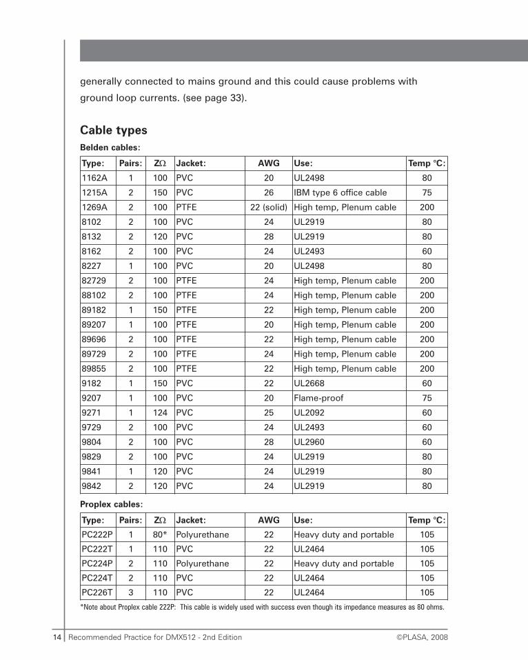
Cable types
Type: Pairs: ZΩ Jacket: AWG Use: Temp °C:
1162A 1 100 PVC 20 UL2498 80
1215A 2 150 PVC 26 IBM type 6 office cable 75
1269A 2 100 PTFE 22 (solid) High temp, Plenum cable 200
8102 2 100 PVC 24 UL2919 80
8132 2 120 PVC 28 UL2919 80
8162 2 100 PVC 24 UL2493 60
8227 1 100 PVC 20 UL2498 80
82729 2 100 PTFE 24 High temp, Plenum cable 200
88102 2 100 PTFE 24 High temp, Plenum cable 200
89182 1 150 PTFE 22 High temp, Plenum cable 200
89207 1 100 PTFE 20 High temp, Plenum cable 200
89696 2 100 PTFE 22 High temp, Plenum cable 200
89729 2 100 PTFE 24 High temp, Plenum cable 200
89855 2 100 PTFE 22 High temp, Plenum cable 200
9182 1 150 PVC 22 UL2668 60
9207 1 100 PVC 20 Flame-proof 75
9271 1 124 PVC 25 UL2092 60
9729 2 100 PVC 24 UL2493 60
9804 2 100 PVC 28 UL2960 60
9829 2 100 PVC 24 UL2919 80
9841 1 120 PVC 24 UL2919 80
9842 2 120 PVC 24 UL2919 80
Type: Pairs: ZΩ Jacket: AWG Use: Temp °C:
PC222P 1 80* Polyurethane 22 Heavy duty and portable 105
PC222T 1 110 PVC 22 UL2464 105
PC224P 2 110 Polyurethane 22 Heavy duty and portable 105
PC224T 2 110 PVC 22 UL2464 105
PC226T 3 110 PVC 22 UL2464 105
Belden cables:
Proplex cables:
*Note about Proplex cable 222P: This cable is widely used with success even though its impedance measures as 80 ohms.
15Recommended Practice for DMX512 - 2nd Edition©PLASA, 2008
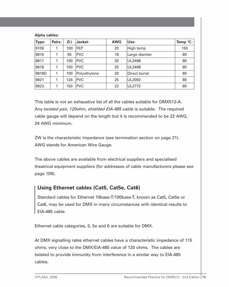
This table is not an exhaustive list of all the cables suitable for DMX512-A.
Any twisted pair, 120ohm, shielded EIA-485 cable is suitable. The required
cable gauge will depend on the length but it is recommended to be 22 AWG,
24 AWG minimum.
ZW is the characteristic impedance (see termination section on page 21).
AWG stands for American Wire Gauge.
The above cables are available from electrical suppliers and specialised
theatrical equipment suppliers (for addresses of cable manufacturers please see
page 109).
Using Ethernet cables (Cat5, Cat5e, Cat6)
Standard cables for Ethernet 10base-T/100base-T, known as Cat5, Cat5e or
Cat6, may be used for DMX in many circumstances with identical results to
EIA-485 cable.
Ethernet cable categories, 5, 5e and 6 are suitable for DMX.
At DMX signalling rates ethernet cables have a characteristic impedance of 115
ohms, very close to the DMX/EIA-485 value of 120 ohms. The cables are
twisted to provide immunity from interference in a similar way to EIA-485
cables.
Type: Pairs: ZΩ Jacket: AWG Use: Temp °C:
9109 1 100 FEP 20 High temp 150
9816 1 95 PVC 18 Large diamter 80
9817 1 100 PVC 20 UL2498 80
9818 1 100 PVC 20 UL2498 80
9818D 1 100 Polyethylene 20 Direct burial 80
9821 1 124 PVC 25 UL2092 80
9823 1 150 PVC 22 UL2772 80
Alpha cables:
16 Recommended Practice for DMX512 - 2nd Edition ©PLASA, 2008
Rules for using Ethernet cables:
• The cable must be suitably mechanically protected from abrasion and
crushing. Cat5 cables are not very physically robust. Do not use them
unless they are well protected.
• The cable must not be subjected to repeated bending. Cat5 cables have
stiff cores that will break after a few flexings.
• There must be no sources of high-energy electromagnetic interference
nearby. Cat5 cables (the unshielded type, which is the most common) do
not provide the same degree of protection from interference as a proper
EIA-485 shielded cable. Equipment that may interfere with DMX on
Ethernet cable includes radio and television transmitters, welding
equipment, induction heaters, radio sources such as radar, X-ray or MRI
and CAT scanners, Heavy industrial machinery, and other equipment using
high power electricity. If in doubt about the local electromagnetic
environment do not use an Ethernet cable without shielding.
• In Europe, and other places that have adopted the same technical
regulations as Europe for electromagnetic compatibility, Ethernet cables
used for DMX must be either shielded or inside metallic conduits
connected to earth. This is to prevent the cable from producing, or being
susceptible to, interference with other equipment.
• Ethernet cable cores are small-gauge and fragile and are not suited to
screw-down connectors and terminals. The action of screwing down on to
a cable core will often break it or weaken it so it breaks later. Cat5 and
similar wire should only be terminated in insulation-displacement
connectors or in pressure terminals with protective leaves suitable for
fine-gauge signal wires. The cable should be secured so that no
mechanical strain is put on the cores.
17Recommended Practice for DMX512 - 2nd Edition©PLASA, 2008
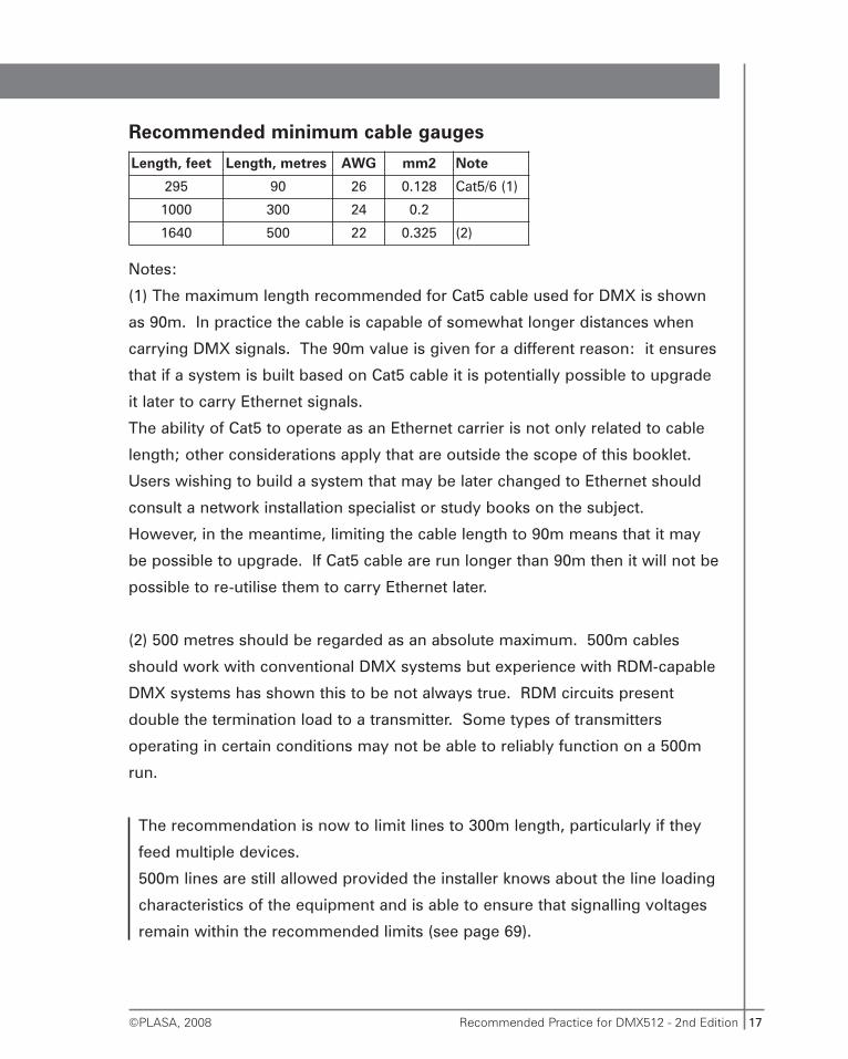
Recommended minimum cable gauges
Notes:
(1) The maximum length recommended for Cat5 cable used for DMX is shown
as 90m. In practice the cable is capable of somewhat longer distances when
carrying DMX signals. The 90m value is given for a different reason: it ensures
that if a system is built based on Cat5 cable it is potentially possible to upgrade
it later to carry Ethernet signals.
The ability of Cat5 to operate as an Ethernet carrier is not only related to cable
length; other considerations apply that are outside the scope of this booklet.
Users wishing to build a system that may be later changed to Ethernet should
consult a network installation specialist or study books on the subject.
However, in the meantime, limiting the cable length to 90m means that it may
be possible to upgrade. If Cat5 cable are run longer than 90m then it will not be
possible to re-utilise them to carry Ethernet later.
(2) 500 metres should be regarded as an absolute maximum. 500m cables
should work with conventional DMX systems but experience with RDM-capable
DMX systems has shown this to be not always true. RDM circuits present
double the termination load to a transmitter. Some types of transmitters
operating in certain conditions may not be able to reliably function on a 500m
run.
The recommendation is now to limit lines to 300m length, particularly if they
feed multiple devices.
500m lines are still allowed provided the installer knows about the line loading
characteristics of the equipment and is able to ensure that signalling voltages
remain within the recommended limits (see page 69).
Length, feet Length, metres AWG mm2 Note
295 90 26 0.128 Cat5/6 (1)
1000 300 24 0.2
1640 500 22 0.325 (2)
18 Recommended Practice for DMX512 - 2nd Edition ©PLASA, 2008
Connections
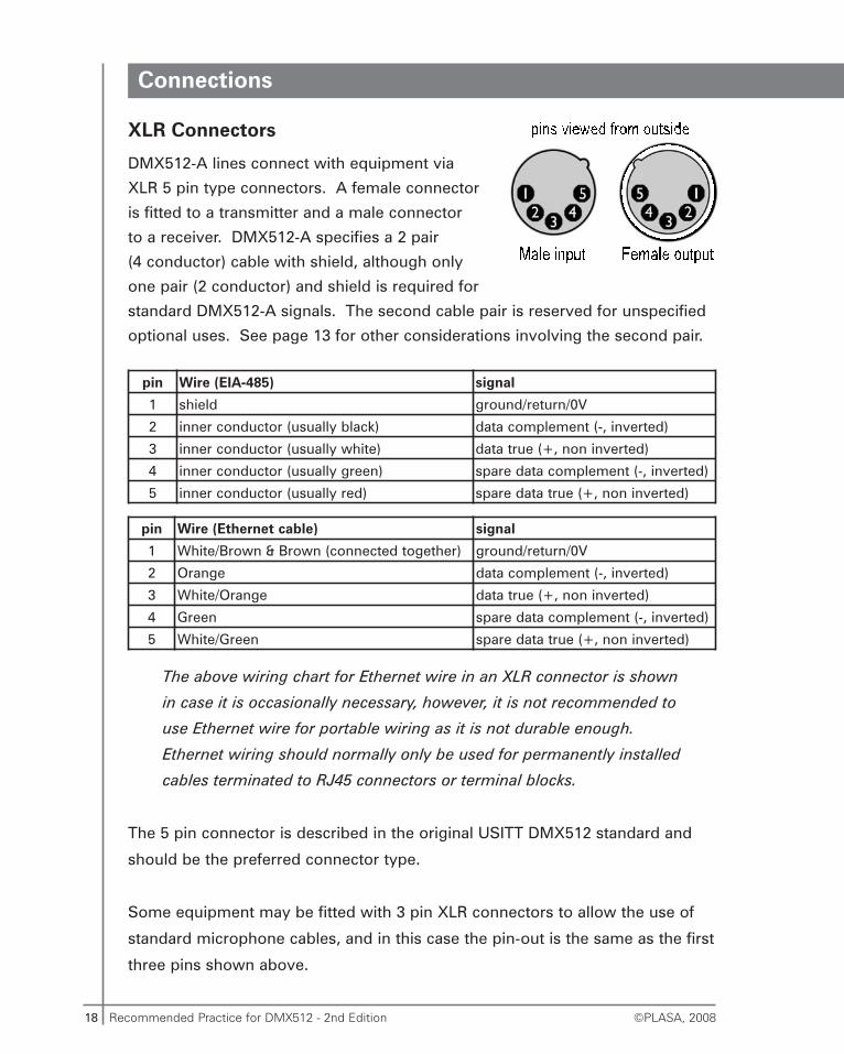
XLR Connectors
DMX512-A lines connect with equipment via
XLR 5 pin type connectors. A female connector
is fitted to a transmitter and a male connector
to a receiver. DMX512-A specifies a 2 pair
(4 conductor) cable with shield, although only
one pair (2 conductor) and shield is required for
standard DMX512-A signals. The second cable pair is reserved for unspecified
optional uses. See page 13 for other considerations involving the second pair.
The above wiring chart for Ethernet wire in an XLR connector is shown
in case it is occasionally necessary, however, it is not recommended to
use Ethernet wire for portable wiring as it is not durable enough.
Ethernet wiring should normally only be used for permanently installed
cables terminated to RJ45 connectors or terminal blocks.
The 5 pin connector is described in the original USITT DMX512 standard and
should be the preferred connector type.
Some equipment may be fitted with 3 pin XLR connectors to allow the use of
standard microphone cables, and in this case the pin-out is the same as the first
three pins shown above.
pin Wire (EIA-485) signal
1 shield ground/return/0V
2 inner conductor (usually black) data complement (-, inverted)
3 inner conductor (usually white) data true (+, non inverted)
4 inner conductor (usually green) spare data complement (-, inverted)
5 inner conductor (usually red) spare data true (+, non inverted)
pin Wire (Ethernet cable) signal
1 White/Brown & Brown (connected together) ground/return/0V
2 Orange data complement (-, inverted)
3 White/Orange data true (+, non inverted)
4 Green spare data complement (-, inverted)
5 White/Green spare data true (+, non inverted)
19Recommended Practice for DMX512 - 2nd Edition©PLASA, 2008
The use of 3 pin connectors is not recommended and is not part of
the DMX512-A standard.
Microphone and audio cables are not ideally suited for DMX512
transmission. It is strongly recommended that only cable suitable for
high-speed data transmission, such as one of the types listed above,
is used.
When 3 pin XLRs must be used care should be taken to ensure the user
cannot accidentally plug them into microphone inputs with phantom
power. Phantom microphone power may damage DMX equipment.
It should also be noted that DMX512-A signals may be routed down other
cabling systems, for instance to colour changers, typically via 4 pin XLR style
connectors. The same rules apply regarding cable characteristics and generally
this will require the use of cable specially designed for this purpose.
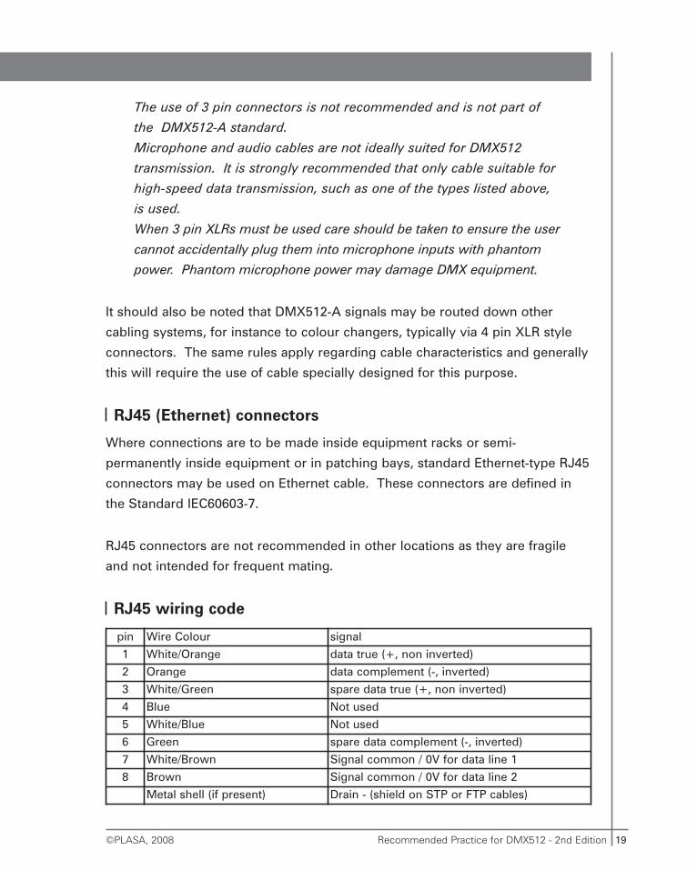
RJ45 (Ethernet) connectors
Where connections are to be made inside equipment racks or semi-
permanently inside equipment or in patching bays, standard Ethernet-type RJ45
connectors may be used on Ethernet cable. These connectors are defined in
the Standard IEC60603-7.
RJ45 connectors are not recommended in other locations as they are fragile
and not intended for frequent mating.
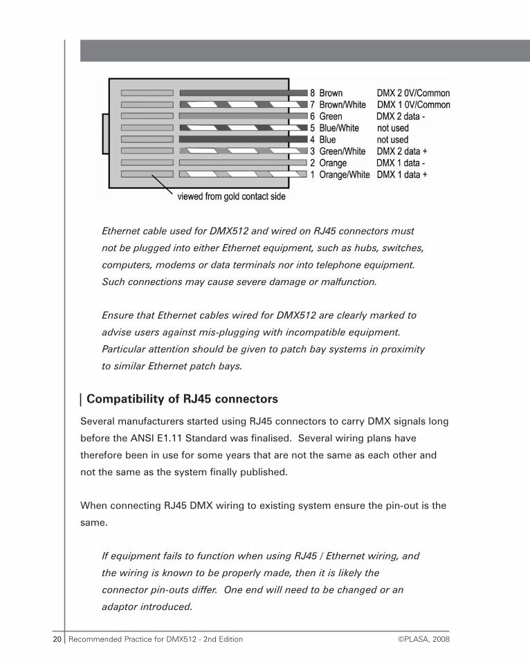
RJ45 wiring code
pin Wire Colour signal
1 White/Orange data true (+, non inverted)
2 Orange data complement (-, inverted)
3 White/Green spare data true (+, non inverted)
4 Blue Not used
5 White/Blue Not used
6 Green spare data complement (-, inverted)
7 White/Brown Signal common / 0V for data line 1
8 Brown Signal common / 0V for data line 2
Metal shell (if present) Drain - (shield on STP or FTP cables)
20 Recommended Practice for DMX512 - 2nd Edition ©PLASA, 2008
Ethernet cable used for DMX512 and wired on RJ45 connectors must
not be plugged into either Ethernet equipment, such as hubs, switches,
computers, modems or data terminals nor into telephone equipment.
Such connections may cause severe damage or malfunction.
Ensure that Ethernet cables wired for DMX512 are clearly marked to
advise users against mis-plugging with incompatible equipment.
Particular attention should be given to patch bay systems in proximity
to similar Ethernet patch bays.
Compatibility of RJ45 connectors
Several manufacturers started using RJ45 connectors to carry DMX signals long
before the ANSI E1.11 Standard was finalised. Several wiring plans have
therefore been in use for some years that are not the same as each other and
not the same as the system finally published.
When connecting RJ45 DMX wiring to existing system ensure the pin-out is the
same.
If equipment fails to function when using RJ45 / Ethernet wiring, and
the wiring is known to be properly made, then it is likely the
connector pin-outs differ. One end will need to be changed or an
adaptor introduced.
21Recommended Practice for DMX512 - 2nd Edition©PLASA, 2008
Termination
Incorrect or missing termination is probably the single most common reason for
faulty DMX512-A systems.
The terminator is a resistor fitted between the two data lines (pins 2 & 3 of an
XLR 5 pin connector) at the end of the cable furthest from the transmitter.
If a terminating resistor is not fitted, when the signal arrives at the far end of the
line it is ‘reflected’ back down the line to the transmitter. At certain line lengths
and conditions the reflected signal can cancel out the real signal, resulting in
errors. A terminator resistor ‘soaks away’ the signal at the far end of the line,
preventing reflections.
The resistor value is typically between 110-130 ohms ½ watt. Previous simple
DMX systems, with no RDM features, could be terminated at the far end only,
as the transmitter was always at the near end. RDM systems allow any device
to be a transmitter therefore both ends of the line could be distant from the
transmitter.
It is recommended that all DMX512-A systems are built with
a terminator at each end of the line.
The far-end terminator is a simple resistor, as before. The near-end
(console end) terminator is a resistor network (see Line Biasing on
page 23 for details).
The termination resistance should ideally match the ‘characteristic impedance’
of the cable (see column ZΩ in the cable lists on page 14). The characteristic
impedance is the impedance of a line of infinite length, which, by definition,
would not suffer from reflections. Placing a resistor equal to the characteristic
impedance at each end of a line of finite length causes the cable to behave as if
it were infinitely long, from the transmission circuit’s point of view.
Cables for DMX512-A have a characteristic impedance of approx. 100-150
ohms. RS-422 (a predecessor of EIA-485) is optimised for 100 ohm lines,
EIA-485 for 120 ohm lines.
22 Recommended Practice for DMX512 - 2nd Edition ©PLASA, 2008
DMX512-A systems may appear to work fine without the terminator resistors
(indeed they may be forgotten or lost without anyone noticing at first) until they
unexpectedly fail.
Always check for the presence of the terminator resistors. A simple resistance
check across one end of the cable (turn off all devices on the line and measure
resistance between pins 2 and 3) can reveal the presence of the terminator
resistor, or faulty (too much or too little) termination. This resistance should be
around 60-75 ohms on short or heavy-gauge cables and may be higher with very
long cables due to the additional resistance of the cable conductors themselves.
The two 120 ohm resistors together in parallel results in a measured
resistance of 60 ohms.
If the resistance measures as approximately 120 ohms then the
network is probably a correctly terminated simple DMX network. This
should function properly for conventional DMX but will not function
with RDM.
Some devices are fitted with a switch to select an internal terminator. This
switch may be labelled ‘end-of-line’ or ‘last-rack’. It should only be switched in
on the last device on the line.
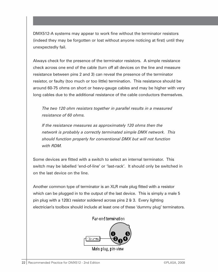
Another common type of terminator is an XLR male plug fitted with a resistor
which can be plugged in to the output of the last device. This is simply a male 5
pin plug with a 120Ω resistor soldered across pins 2 & 3. Every lighting
electrician’s toolbox should include at least one of these ‘dummy plug’ terminators.
23Recommended Practice for DMX512 - 2nd Edition©PLASA, 2008
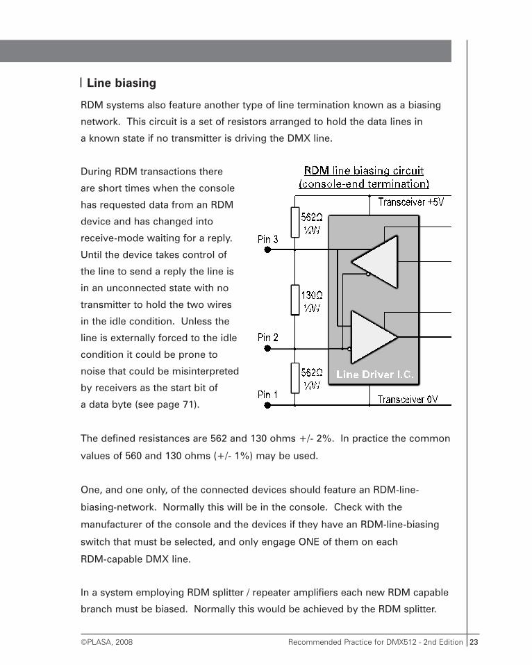
Line biasing
RDM systems also feature another type of line termination known as a biasing
network. This circuit is a set of resistors arranged to hold the data lines in
a known state if no transmitter is driving the DMX line.
During RDM transactions there
are short times when the console
has requested data from an RDM
device and has changed into
receive-mode waiting for a reply.
Until the device takes control of
the line to send a reply the line is
in an unconnected state with no
transmitter to hold the two wires
in the idle condition. Unless the
line is externally forced to the idle
condition it could be prone to
noise that could be misinterpreted
by receivers as the start bit of
a data byte (see page 71).
The defined resistances are 562 and 130 ohms +/- 2%. In practice the common
values of 560 and 130 ohms (+/- 1%) may be used.
One, and one only, of the connected devices should feature an RDM-line-
biasing-network. Normally this will be in the console. Check with the
manufacturer of the console and the devices if they have an RDM-line-biasing
switch that must be selected, and only engage ONE of them on each
RDM-capable DMX line.
In a system employing RDM splitter / repeater amplifiers each new RDM capable
branch must be biased. Normally this would be achieved by the RDM splitter.
24 Recommended Practice for DMX512 - 2nd Edition ©PLASA, 2008
Connection of more than one biasing network to an RDM line, and also to
a non-RDM line, may cause errors or malfunction. If an RDM system is prone
to errors check that one and one only line biasing network is activated.
Line biasing is not necessary on conventional DMX lines that are not RDM
capable.
On lines that are RDM capable, and enabled for RDM transactions, the line must
be biased even if there are no RDM responder devices on that line. The
console or splitter may place the line into the floating, disconnected state even
though no reply will take place back to that particular output.
Biasing may be applied to normal DMX lines with no ill effect. Because of this
it is recommended for reasons of simplicity to bias all DMX lines whenever
a switch or option for biasing is present.
All DMX lines with RDM enabled must be terminated at both ends
even if no actual RDM responder devices are connected and only
conventional DMX (receive-only) devices are connected.
One, and one only, of the connected devices on each separate DMX or
DMX-RDM line should feature an RDM-line-biasing-network.
25Recommended Practice for DMX512 - 2nd Edition©PLASA, 2008
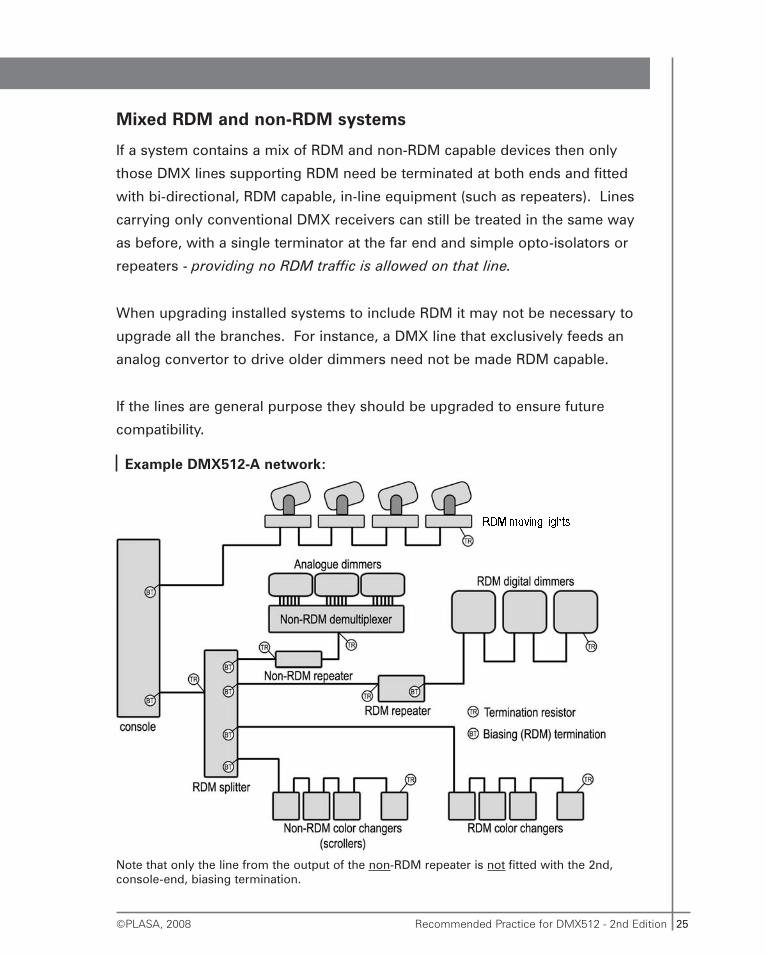
Mixed RDM and non-RDM systems
If a system contains a mix of RDM and non-RDM capable devices then only
those DMX lines supporting RDM need be terminated at both ends and fitted
with bi-directional, RDM capable, in-line equipment (such as repeaters). Lines
carrying only conventional DMX receivers can still be treated in the same way
as before, with a single terminator at the far end and simple opto-isolators or
repeaters - providing no RDM traffic is allowed on that line.
When upgrading installed systems to include RDM it may not be necessary to
upgrade all the branches. For instance, a DMX line that exclusively feeds an
analog convertor to drive older dimmers need not be made RDM capable.
If the lines are general purpose they should be upgraded to ensure future
compatibility.
Example DMX512-A network:
Note that only the line from the output of the non-RDM repeater is not fitted with the 2nd,console-end, biasing termination.
26 Recommended Practice for DMX512 - 2nd Edition ©PLASA, 2008
Using RDM with devices that do not check the Start code
Some old DMX devices exist that do not check the Start code. They cannot
distinguish RDM traffic from normal DMX levels. If they are used on an
RDM-enabled system they will respond to RDM messages as if they were
dimmer levels and produce the appearance of errors or flicker.
If an existing system includes devices that are so simple and basic (and
non-compliant with any DMX specification, past or present) that they do not
check the Start code then they must be isolated from RDM traffic. Certain types
of RDM splitters offer features to disable RDM traffic on each output port
independently. Alternatively there are several makes of DMX ‘translators’ that
can filter out undesired Start codes and ensure that only normal dimmer level
information is passed on.
Mixing RDM and non-RDM devices downstream of splitters
It is not advised to place RDM capable devices downstream of a non-RDM
capable splitter that is fed with RDM data from the main controller. If possible
the input of the non-RDM-capable splitter should be isolated from RDM traffic.
There is a theoretical, but rather improbable, situation where the RDM device
would respond to a message and corrupt the output of the splitter. The
corruption could possibly be mis-read by other non-RDM devices on that DMX
branch causing errors or flicker.
This is a real risk only if an RDM device, which has been discovered and
addressed elsewhere on the system, is then moved downstream of the non-
RDM splitter.
It is advisable, but not compulsory, to connect RDM-capable devices
to RDM-capable splitters and not to ordinary non-RDM-capable
splitters wherever practical.
27Recommended Practice for DMX512 - 2nd Edition©PLASA, 2008
DMX512 A Networks
DMX512-A will only function correctly, especially with long cables, when
a single line is employed from the first device to the last device.
A transmitter, i.e. a console or controller, is now considered to be
simply another device and could in principle be located anywhere
along the DMX line. However, because of the need to bias the line in
combination with termination, and because this is normally present in
the console or transmitter, the normal practice will be to place the
console at one end of the line.
A line can have up to 32 unit loads (less if the receivers do not comply with the
EIA-485 spec. - see page 35) hung off it anywhere down its length. A typical
EIA-485 receiver represents approximately one unit load. These devices should
connect to the line with very short (less than 30cm - 12") cables in order to
prevent the creation of ‘Y’ splits (see below), but in practice this length can be
extended to several metres. This is normally accom-plished inside the devices
which, if fitted with input and pass-through connectors, can be daisy-chained
together.
The EIA-485 link as used by DMX512-A is capable of operation on lines of up
to 1km (3281’) in length. This is the absolute maximum. It is recommended to
keep the line length below about 300m (1000’), beyond which signal amplifiers
(repeaters) should be considered.
When very long lines are employed, care should be taken to select a cable with
sufficient conductor cross-sectional area. The resistance of the cable must
allow at least 0.2V to be developed across each of the 120 ohm terminator
resistors at each end of the cable when driven with as little as 2V at the
transmitter. Do not use a cable with conductors less than 22 AWG. in size on
long lines. The D.C. resistance should not be confused with the characteristic
impedance. D.C. resistance can be measured with a standard ohmmeter and
should not exceed approx. 200 ohms per conductor.
28 Recommended Practice for DMX512 - 2nd Edition ©PLASA, 2008
DMX512-A lines should be kept away from power cabling, particularly load
cables from dimmers, and should not be run in conduit or trunking with power
cables or cables carrying large currents as this could cause interference and
errors.
Simple splitter cables (‘Y’ leads)
Do not use simple splitter cables / ‘Y’ leads / ‘DMX Twofers’
A ‘Y’ lead is a hard-wired connection between a male (console-side) connector
and two female (dimmer-side) connectors; all pins 1 are joined, all pins 2 etc.
If ‘Y’ leads are used, particularly at a distance from the transmitter, then
a complex set of reflections will ensue, causing severe signal degradation
and increased error rate.
Splitter amplifiers are the only reliable method for splitting the
DMX512-A network into different branches. See next section.
29Recommended Practice for DMX512 - 2nd Edition©PLASA, 2008
Repeater and Splitter / Distribution amplifiers
Simple Repeater amplifiers as described in the 1st edition will NOT
WORK with DMX512-A systems that employ RDM or any of the
advanced features that use the DMX line as a bi-directional link.
Simple Repeaters (non RDM capable)
When very long lines are employed, or more than 32 devices are required, it is
necessary to boost the signal through a repeater amplifier, also known as a
buffer amplifier. The input of the repeater amplifier is like the input of any other
DMX512-A device; the output is like that of any other DMX512-A transmitter.
The line from the console should be terminated in the normal way - the
repeater need not be at the end of the line. The second, repeated, line is also
terminated at each end.
Lines can be repeated in this way many times before re-generation errors occur,
providing that the repeater amplifiers, and particularly opto-isolated circuits, are
sufficiently fast. If these circuits cannot reproduce the rising and falling edges
of the signal without some distortion or delay, the chaining together of such
devices will eventually corrupt the signal.
Repeater amplifiers that only restore the electrical levels of the DMX512-A
signal can only be used with simple DMX systems not using any RDM
bi-directional features. Such simple amplifiers do not re-create the timings
between the individual bits. Re-generation of the timing can only be achieved
with special equipment that decodes the DMX512-A input and then
re-transmits it through a separate encoder (UART) and output driver circuit.
Such devices can also be used to modify the DMX512-A timings in order to
allow the use of non-compliant DMX512-A receivers with modern fast consoles
(see page 78).
RDM bi-directional Repeater amplifiers
Repeater amplifiers capable of handling DMX-RDM signals contain processors
that read in the data stream and decode the packet Start codes to see if an RDM
30 Recommended Practice for DMX512 - 2nd Edition ©PLASA, 2008
message has been sent that requires reversing the line connection in order to
receive a reply from a device.
Only amplifiers specifically designed to handle RDM can perform this task.
Built-in repeaters
Many devices, particularly colour changers and large dimmer racks, have built-
in repeater amplifiers to re-generate the DMX512-A signals. These designs are
usually fitted with a relay to switch the input directly to the output in the event
of power failure or malfunction so that subsequent units are still fed with data.
Note that this switch-over is purely mechanical and is not synchronised to the
DMX512-A data. As the contacts change-over there will be a brief loss of
signal. Devices down-line from the changeover may receive bad DMX512-A
data. This will not be corrected until the next new packet of levels arrives.
Thus, with a slow console the wrong dimmer levels may persist long enough to
be very noticeable.
When the repeater is active, each output is driving a ‘new’ DMX512-A line,
which should be terminated in the normal way. However, if these lines are very
short, e.g. to the next module in a rack, termination would not normally be
necessary. Still, it is desirable for the following reason. When the outputs are
routed directly from the inputs, if the module is off or has failed, the termination
is also removed, thus the next module will provide the termination. The last
module would have a terminating plug in its output socket. If all the modules in
the rack are off, or have failed, the line will be terminated into the plug. With
such a system any other devices will always see a correctly terminated line.
Built-in repeaters should not be expected to be fully DMX-RDM
compliant and will not pass RDM traffic back to a console.
If in doubt about presence of built-in repeaters, and how this can affect the
network, try measuring the termination resistance while cycling power on each
31Recommended Practice for DMX512 - 2nd Edition©PLASA, 2008
of the devices on the line. The resistance should remain substantially the same
(60-75 ohms) and other devices down-stream should continue to respond to
DMX512-A levels, although there may be glitches in their operation, as
described above.
Splitters
Splitter amplifiers are like repeaters but they have more than one output. Each
output drives the same signal but down separate lines. These are also known
as distribution amplifiers since they allow the DMX512-A line to be replicated
and sent in different directions to devices distributed throughout a building or
concert site.
There are important differences between isolating and non isolating
repeaters and splitters which are discussed below (see page 33).
DMX512-A networks using RDM bi-directional features will only work if
Splitters are used that are specially designed to handle RDM signals.
Ordinary splitters will prevent RDM information from being sent back
from devices. Only simple DMX control of levels, in one direction only
from the console to the devices, will continue to function.
RDM messages should, if possible, be disabled in a console or
controller if RDM devices are connected downstream of non-RDM
capable in-line equipment. Failure to prevent RDM transmission in
this case may result in system malfunction.
Connection of pins 4 & 5
The second pair in the DMX512-A line is described in the DMX512-A specification
but its use is not defined. There are many devices and systems in the field that
use the second pair, on pins 4 and 5, for various purposes. Some systems
implement talkback using the pair as a return EIA-485 line to the console or
a separate fault and status display unit. Other systems may employ the two wires
of the 2nd pair as direct control signals, for temperature indication for instance.
32 Recommended Practice for DMX512 - 2nd Edition ©PLASA, 2008
Most DMX512-A devices, with input and pass-through connectors for daisy-
chaining, simply connect the first three pins; 1 to 1, 2 to 2 and 3 to 3. Not all
devices also connect pins 4 to 4 and 5 to 5.
Talkback systems which utilise the second pair as a return line require special
distribution amplifiers and custom bi-directional repeaters and isolators.
The ANSI E1.11-2008 (USITT DMX512-A) Standard now specifies how signals
should behave on the 2nd line connected to pins 4 & 5. A number of separate
methods are allowed as defined in Annexe B of the Standard. Readers desiring
to use pins 4 & 5 for some supplementary purpose should read the
requirements for electrical levels, registration of Alternate Start codes
(if required) and suitable markings in this annexe.
33Recommended Practice for DMX512 - 2nd Edition©PLASA, 2008
Network Isolation
Grounding
In the manufacture of DMX512-A equipment there are several approved
methods for connection of the signal common, or line ground, to the
mains/chassis ground. The EIA-485 standard requires that the line ground be
tied to the mains ground in both the transmitters and receivers, unless the
common-mode voltage exceeds the specified values (see page 70). In practice
this means that manufacturers sometimes connect to mains ground and
sometimes leave the line ground floating.
The ANSI E1.11-2008 (USITT DMX512-A) version of the DMX Standard now
includes Annexe A which defines the various different grounding connection
methods that may be used and how they interact with each other. For full
details read that section of the Standard. Here follows general advice on the
basic requirements for grounding to ensure correct operation, this is, however,
not the only way it may be done.
The ground wire of the line should be connected to mains ground at the
transmitting end in most DMX512-A installations (except battery powered
transmitters, testers etc.) for reasons of interference rejection. In a standard
EIA-485 set-up the line ground may also be connected to the receiver mains
ground. This can cause special problems with large lighting systems, ranging
from signal errors to catastrophic failures.
It is important when installing a DMX512-A network to determine which units
have their DMX512-A cable shield connected to mains ground and which do
not. This can be ascertained with a simple continuity check between pin 1 of
the device’s connector and mains or chassis ground.
If all the devices (except the transmitter / console) are isolated from ground it
will not normally be necessary to take any special precautions. If one or more
devices are grounded it may prove necessary to install isolation circuitry to part
or all of the DMX512-A network.
34 Recommended Practice for DMX512 - 2nd Edition ©PLASA, 2008
Data errors caused by poor grounding
When equipment is widely separated in different sites in a large building, or
outdoors, there can be quite large voltage differences between the local
grounding points of each site. These are due to currents flowing in the ground
cables back to the common ground point, which may be located at a great
distance, e.g. the sub-station transformer.
EIA-485 specifies that the receivers and transmitters can tolerate up to +12V or
-7V ‘common mode voltage’. This is the voltage that can be applied safely
between a data wire and the local ground point for that receiver or transmitter.
If the common mode voltage is exceeded the EIA-485 devices will certainly
produce errors and may eventually fail.
Safety problems caused by poor grounding
If a fault develops to ground, for instance in a luminaire, and the ground of the
dimming system is faulty, the fault current will flow back to ground down the
only remaining ground connection - the DMX512-A cable shield. Large enough
fault currents can cause the DMX512-A cable to explode - literally! Furthermore,
such a fault would be very likely to destroy all the circuits connected to the line
(this really does happen). When transmitters and receivers (console and
dimmers) are located in close proximity and connected to the same mains
supply such a situation is unlikely in practice. The problem is more severe
when the dimming equipment is fed from a separate supply, or worse still a
generator with inadequate grounding.
The DMX cable shield is connected to earth/ground to preserve signal
integrity and/or to prevent electromagnetic interference. This
connection is NOT a life-safety earth and its presence or absence does
not affect a product’s basic protection from electrocution AT ALL.
Products must be grounded/earthed as required for safety according to
the manufacturer’s instructions independently of the DMX cable shield.
35Recommended Practice for DMX512 - 2nd Edition©PLASA, 2008
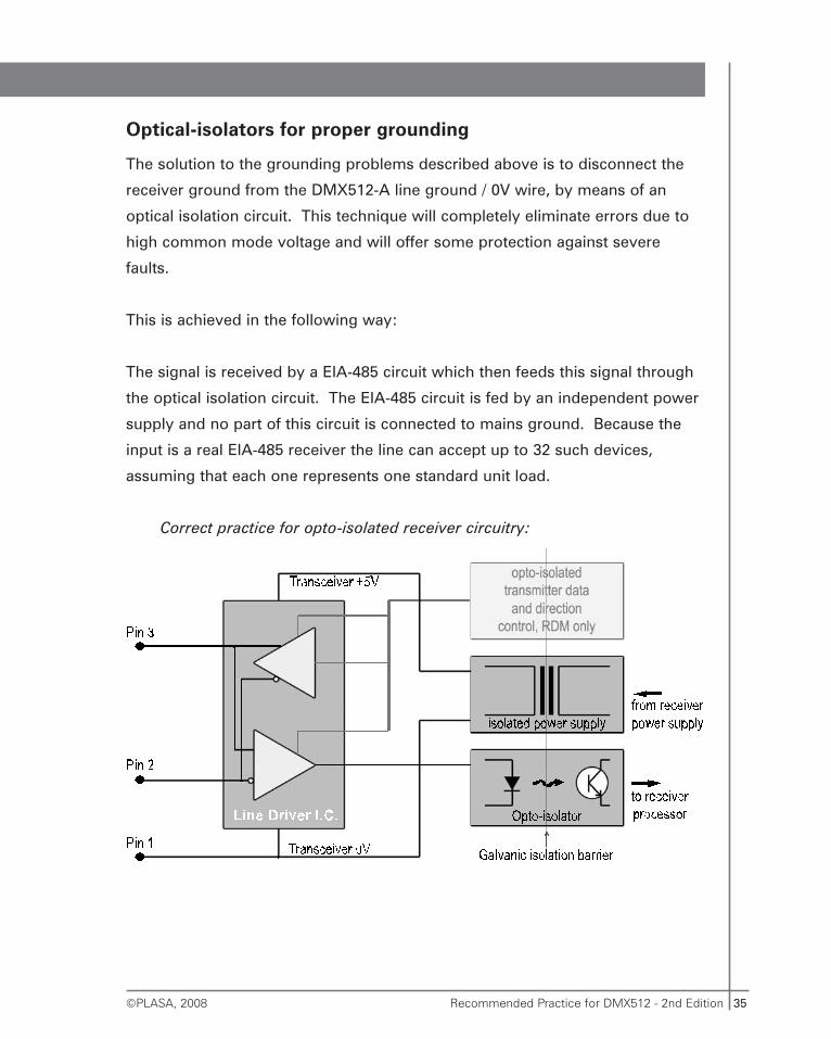
Optical-isolators for proper grounding
The solution to the grounding problems described above is to disconnect the
receiver ground from the DMX512-A line ground / 0V wire, by means of an
optical isolation circuit. This technique will completely eliminate errors due to
high common mode voltage and will offer some protection against severe
faults.
This is achieved in the following way:
The signal is received by a EIA-485 circuit which then feeds this signal through
the optical isolation circuit. The EIA-485 circuit is fed by an independent power
supply and no part of this circuit is connected to mains ground. Because the
input is a real EIA-485 receiver the line can accept up to 32 such devices,
assuming that each one represents one standard unit load.
Correct practice for opto-isolated receiver circuitry:
36 Recommended Practice for DMX512 - 2nd Edition ©PLASA, 2008
Opto-isolation in RDM systems
Simple opto-isolators that operate in one direction only will not function
properly in DMX-RDM systems; they are unable to detect RDM messages and
turn round the direction of communication for a device reply. If opto-isolation is
necessary in an RDM network (and it often will be necessary) then you must
use RDM capable Repeater amplifiers, with opto-isolation (see page 29).
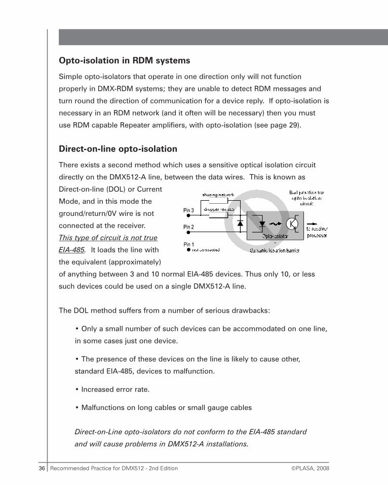
Direct-on-line opto-isolation
There exists a second method which uses a sensitive optical isolation circuit
directly on the DMX512-A line, between the data wires. This is known as
Direct-on-line (DOL) or Current
Mode, and in this mode the
ground/return/0V wire is not
connected at the receiver.
This type of circuit is not true
EIA-485. It loads the line with
the equivalent (approximately)
of anything between 3 and 10 normal EIA-485 devices. Thus only 10, or less
such devices could be used on a single DMX512-A line.
The DOL method suffers from a number of serious drawbacks:
• Only a small number of such devices can be accommodated on one line,
in some cases just one device.
• The presence of these devices on the line is likely to cause other,
standard EIA-485, devices to malfunction.
• Increased error rate.
• Malfunctions on long cables or small gauge cables
Direct-on-Line opto-isolators do not conform to the EIA-485 standard
and will cause problems in DMX512-A installations.
37Recommended Practice for DMX512 - 2nd Edition©PLASA, 2008
If DOL devices are used on the same line as true EIA-485 devices, problems can
arise. The DOL devices distort the voltage wave-form. This can cause the
EIA-485 devices to produce errors. The safest use of a DOL device is as the
only receiver at the end of the line.
DOL receivers should be eliminated wherever possible. Where DOL
devices must be used they should be isolated from each other and
from other DMX devices by feeding each of them separately from an
independent splitter output, or from an unused console output.
Opto-isolated Repeaters and Splitters
Both repeaters and splitters are available from a number of manufacturers which
offer opto-isolation between input and output, and in some cases between
individual outputs. A fully isolated splitter can prevent severe faults from
propagating through an entire DMX512-A network and ensures that common
mode problems and other failures are limited to a single branch of the
DMX512-A network. A fully isolated splitter requires a separate source of
isolated power for each of its output circuits. A simple continuity check between
pin 1 of different outputs will reveal if the outputs are isolated from each other.
If sufficiently high voltage is applied to the DMX512 line any devices connected
to it may fail catastrophically and allow the high voltage to enter the equipment.
The presence of opto-isolation does not reduce the need to take normal
precautions for adequately insulating power lines and data lines from each other.
The presence of opto-isolation in a DMX512 network does not
guarantee protection from damage or injury, including fatal
electrocution, caused by severe faults.
European Electromagnetic Compatibility (EMC)
Since the first edition of this booklet was written European legislation has come
into force to limit the effects of electromagnetic interference on electronic

38 Recommended Practice for DMX512 - 2nd Edition ©PLASA, 2008
products. The European Directive 2004-108-EC defines limits for emissions and
immunity for electronic equipment which affects the way that DMX products
are designed, manufactured and installed.
DMX based products used in the European Union, and other countries that
have adopted similar legislation in parallel, should carry the CE mark and state
that they comply with the Directive. Such equipment can be expected to
operate normally in all common environments without suffering from or
producing interference.
Compliance with the CE Standards does not mean that DMX equipment is
immune from any type of interference at any level. Large external
electromagnetic disturbances may still cause failure or errors in DMX systems.
DMX equipment and cabling should be kept away from sources of interference
such as radio and television transmitters, cell phone masts, radiating equipment
such as radar, x-ray, CAT or MRI scanners, large industrial machinery, motor
drives, welding equipment and other similar equipment.
It is strongly recommended, for reasons of product quality and show integrity,
to properly shield all DMX cables and connect metallic shields of equipment
and cables to a good mains earth/ground.
The use of unshielded Ethernet cables is now permitted in some territories,
however, it is preferable to use shielded version of Category wire (such as STP
or FTP versions) or run the Category cable in a metallic conduit connected to
earth unless the user can be reasonably certain that no interference sources are
in proximity. Better to be safe than sorry; use the shielding unless it is really
not possible or you are certain the environment is free from electromagnetic
disturbances.
39Recommended Practice for DMX512 - 2nd Edition©PLASA, 2008
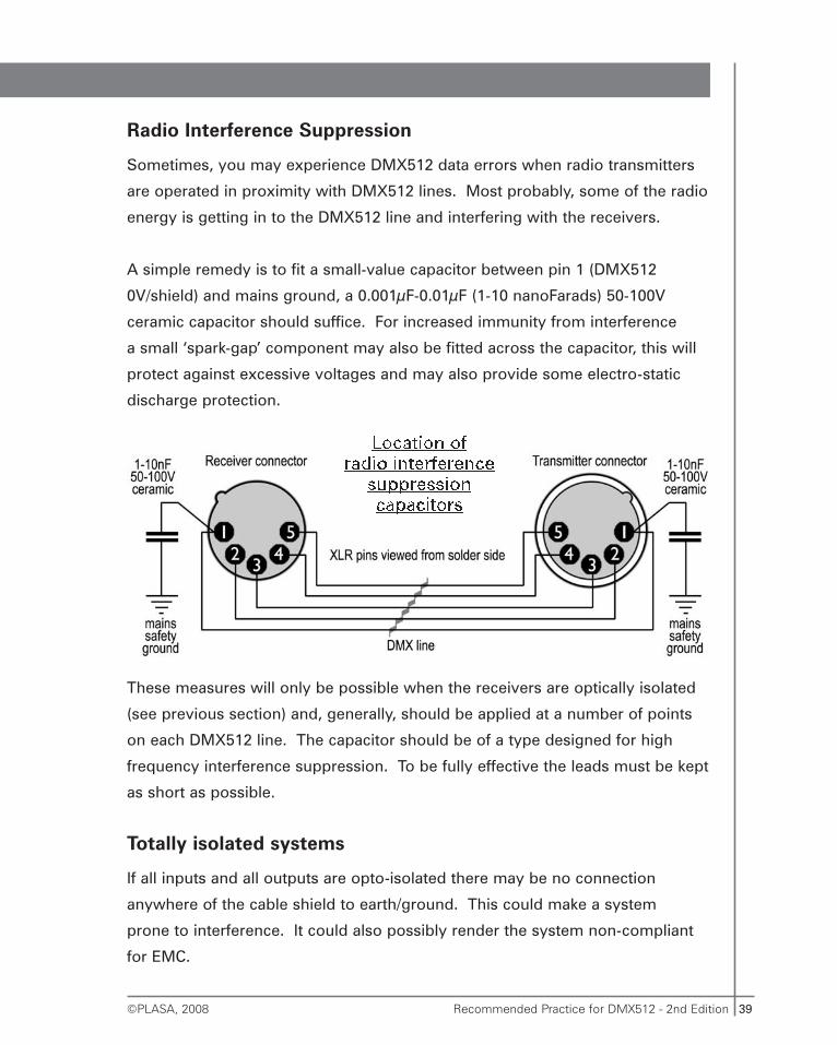
Radio Interference Suppression
Sometimes, you may experience DMX512 data errors when radio transmitters
are operated in proximity with DMX512 lines. Most probably, some of the radio
energy is getting in to the DMX512 line and interfering with the receivers.
A simple remedy is to fit a small-value capacitor between pin 1 (DMX512
0V/shield) and mains ground, a 0.001μF-0.01μF (1-10 nanoFarads) 50-100V
ceramic capacitor should suffice. For increased immunity from interference
a small ‘spark-gap’ component may also be fitted across the capacitor, this will
protect against excessive voltages and may also provide some electro-static
discharge protection.
These measures will only be possible when the receivers are optically isolated
(see previous section) and, generally, should be applied at a number of points
on each DMX512 line. The capacitor should be of a type designed for high
frequency interference suppression. To be fully effective the leads must be kept
as short as possible.
Totally isolated systems
If all inputs and all outputs are opto-isolated there may be no connection
anywhere of the cable shield to earth/ground. This could make a system
prone to interference. It could also possibly render the system non-compliant
for EMC.
40 Recommended Practice for DMX512 - 2nd Edition ©PLASA, 2008
It is recommended that the primary transmitter, i.e. the console for
the majority of systems, connects mains earth / ground directly to the
outgoing DMX cable shields.
Each new DMX branch produced by a opto-isolated splitter / repeater
should be similarly grounded.
41Recommended Practice for DMX512 - 2nd Edition©PLASA, 2008
In-line DMX processing equipment
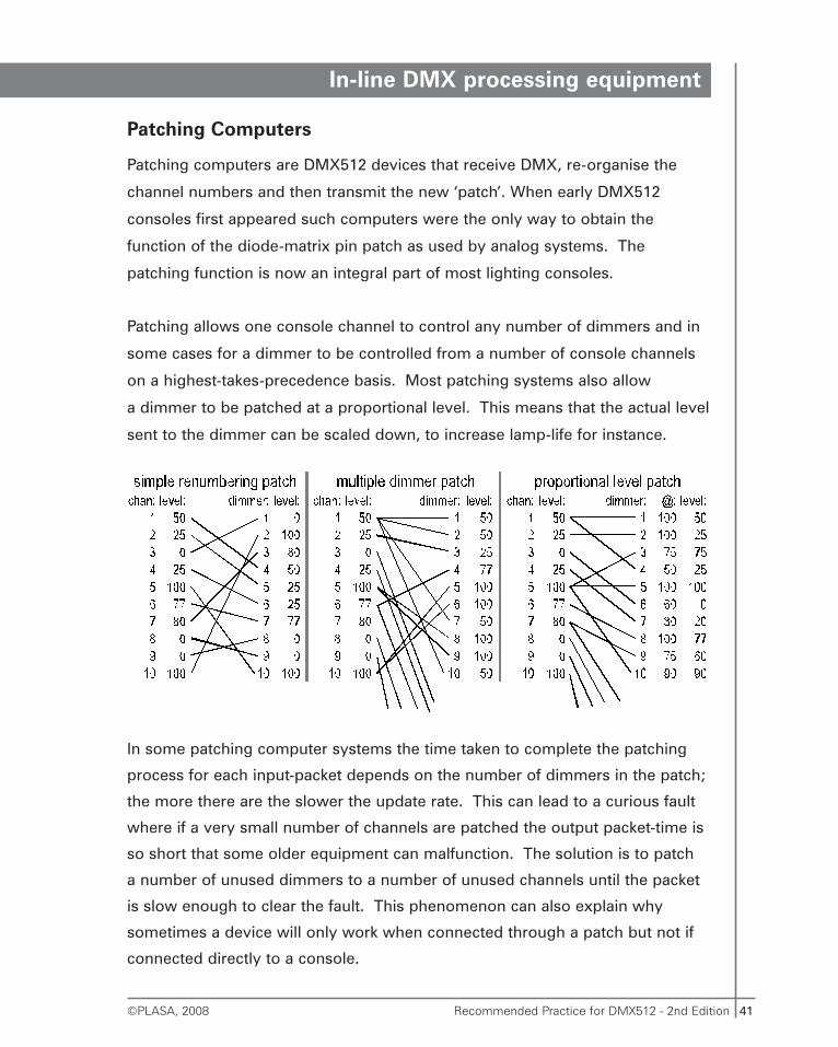
Patching Computers
Patching computers are DMX512 devices that receive DMX, re-organise the
channel numbers and then transmit the new ‘patch’. When early DMX512
consoles first appeared such computers were the only way to obtain the
function of the diode-matrix pin patch as used by analog systems. The
patching function is now an integral part of most lighting consoles.
Patching allows one console channel to control any number of dimmers and in
some cases for a dimmer to be controlled from a number of console channels
on a highest-takes-precedence basis. Most patching systems also allow
a dimmer to be patched at a proportional level. This means that the actual level
sent to the dimmer can be scaled down, to increase lamp-life for instance.
In some patching computer systems the time taken to complete the patching
process for each input-packet depends on the number of dimmers in the patch;
the more there are the slower the update rate. This can lead to a curious fault
where if a very small number of channels are patched the output packet-time is
so short that some older equipment can malfunction. The solution is to patch
a number of unused dimmers to a number of unused channels until the packet
is slow enough to clear the fault. This phenomenon can also explain why
sometimes a device will only work when connected through a patch but not if
connected directly to a console.
42 Recommended Practice for DMX512 - 2nd Edition ©PLASA, 2008
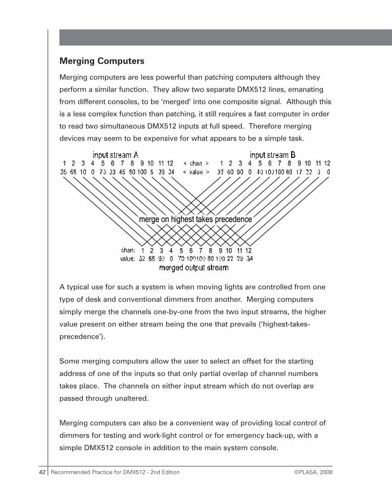
Merging Computers
Merging computers are less powerful than patching computers although they
perform a similar function. They allow two separate DMX512 lines, emanating
from different consoles, to be ‘merged’ into one composite signal. Although this
is a less complex function than patching, it still requires a fast computer in order
to read two simultaneous DMX512 inputs at full speed. Therefore merging
devices may seem to be expensive for what appears to be a simple task.
A typical use for such a system is when moving lights are controlled from one
type of desk and conventional dimmers from another. Merging computers
simply merge the channels one-by-one from the two input streams, the higher
value present on either stream being the one that prevails (‘highest-takes-
precedence’).
Some merging computers allow the user to select an offset for the starting
address of one of the inputs so that only partial overlap of channel numbers
takes place. The channels on either input stream which do not overlap are
passed through unaltered.
Merging computers can also be a convenient way of providing local control of
dimmers for testing and work-light control or for emergency back-up, with a
simple DMX512 console in addition to the main system console.
43Recommended Practice for DMX512 - 2nd Edition©PLASA, 2008
RDM and in-line processing devices
Patching and merging computers cannot generally function on RDM systems
and successfully transfer back RDM replies to the appropriate controller. If the
outputs of two controllers (consoles) are merged then there many technical
difficulties in separating the return messages to the correct console. It would
be also very difficult to ensure the timing criteria are met for each independent
controller, in fact, probably impossible.
RDM systems can thus only have one master controller (console) per
DMX512-A network.
In-Line Backup Computers
These are DMX512 devices that receive DMX, and in normal operation, pass the
signal straight through. In the event of a failure of the main console, i.e. the
absence of DMX512 for a certain period at the device’s input, the back-up
computer takes control of the output.
Simple back-up systems may just maintain the last set of levels from the main
console so that there is a constant supply of DMX512 to the receiving devices,
because some receiving devices do not like the absence of a signal for a long
period.
More sophisticated systems exist which offer a number of pre-recorded lighting
states controllable via faders which can either merge with, or take-over the
console output to provide basic lighting control to run a show. Some of these
devices perform this take-over function automatically.
Some digital dimmers and other devices may include integral merging (i.e. two
or more DMX512 inputs), patching and back-up facilities.
Back-up computers decide that the console has failed if DMX512 is absent for
a certain period of time. In the DMX512 spec. this time is 1 second.
44 Recommended Practice for DMX512 - 2nd Edition ©PLASA, 2008
If a console is very busy, particularly if it is reading or writing to disc, it may
suspend DMX512 output for more than 1 second, in which case the back-up
computer could take-over control. If a system with a back-up computer present
in-line appears to freeze, with loss of console control when certain console
operations are selected, it may be due to this auto-switching feature.
Processing delays
Any computer which is in-line with the DMX512 signal from console to devices
will introduce delays. The in-line device must decode and store the incoming
DMX512 signal and then when it has performed its patching or merging
function (which will also take some time) it can send the resulting levels on to
the devices.
Different types of patching computers apply different rules as to when a new
value at the input should be patched through to the output.
In the simplest scheme an input channel’s value is stored in the computer’s
memory as soon as it arrives and the output function picks this value from the
memory as soon as it is time to send that channel. This method can produce
very little delay, but only if the input arrives just before the output is ready for
that channel. If the input arrives just after the output ‘slot’ then the value has to
be stored for nearly a complete packet time, until the next occurrence of that
channel on the output. If a block of channels on the input changes
simultaneously some of them might update their output on the current packet
with the remainder updating on the next packet. This can lead to uneven fading
and erratic chase behaviour.
The second method adopted is to accept only complete packets of data. Until
a new packet has been completely assembled by the receiver function, the
output function continues to use the previous packet’s data. In practice a
packet can be considered ‘complete’ when all the channels required by the
device have arrived. This method overcomes the ‘partial block update’ effect
described above but produces delays in the order of one output-packet time.
45Recommended Practice for DMX512 - 2nd Edition©PLASA, 2008
The effect of this may still cause jerky operation but as all the channels change
together it may be less noticeable when running chases.
Both of these patching methods yields delays from between 50μs approx. and
the length of the output-packet.
With modern computers these delays should be in the order of 50 milliseconds
(50ms) or less and will only be noticeable on fast chases or bump buttons
(assuming that the console delays are negligible).
Most lighting operators start to perceive delays when they exceed
approximately 150ms and often the DMX512 link will be blamed. Most of the
delays will actually be due to the console and the receiving devices, but as long
as they amount to less than 150ms they will not be noticeable. Thus a system
can seem to slow down when a DMX512 link is introduced if this takes the
combined delays above the 150ms threshold, even though the DMX512 link
itself may only have contributed another 25-30ms of delay.
If many in-line devices are present, e.g. patching, merging and back-up
computers, the accumulation of delays will become intolerable. The delays will
show up as erratic chases, slow bump button response and fader ‘stepping’.
Only one or two such devices should normally be present in-line in order to
minimise these effects.
There exists another class of in-line DMX512 computers which does not ‘buffer’
the whole DMX512 packet but just the most recent level. These devices
synchronise their output to the input packet. When a new data value arrives
this causes the previous channel to be transmitted, the delay is therefore equal
to one slot-time of the input packet, or as little as 44μs. The problem with this
method is that the Break can only be detected after some of it, at least 38μs,
has already elapsed and therefore the regenerated Break may be shorter than
the original, input-packet, Break. Such devices are fairly uncommon as they
require either complex hardware or very fast processing in order to compute
the new output level within one slot-time. See also: Signal timings, page 78.
46 Recommended Practice for DMX512 - 2nd Edition ©PLASA, 2008
A certain amount of delay is inherent in the DMX512 protocol. All
digital, serial communications will always be slower than parallel
analog systems.
RDM processing delays
When RDM is active on a DMX system some time is taken from normal refresh
to send and receive RDM data. The amount of time is variable and intermittent.
Most of the time RDM packets will not take more than about 10-15% of the
available time for sending levels.
Usually this will not be noticeable on conventional dimmers and many moving
light functions. However, devices with very fast response times, such as LED
luminaires or moving lights, where pan and tilt movement directly tracks the
DMX signal, may exhibit erratic updates.
The most RDM traffic is produced during the device discovery process, prior to
addressing. It is possible for the discovery process to take as much as 50% of
the available transmission time. It is recommended to run a trial of device
discovery during a rehearsal to see if any visible impact can be noticed.
Some equipment may provide a way to disable device discovery during
a performance to ensure smooth DMX updates.
Normally the use of RDM to periodically check device status should not
produce any undesirable visible artefacts.
Analog Converters
Analog conversion comes in two forms: Analog to DMX512 conversion and
DMX512 to analog conversion.
Many older lighting devices still use 0-10 volt, analog control signals. In
addition, some modern devices use analog control signals because a built-in
DMX512 decoder is too expensive.
47Recommended Practice for DMX512 - 2nd Edition©PLASA, 2008
0-10V control is defined in the Standard ANSI E1.3-2001 (R2011)
Analog to DMX512 converters allow the use of simple consoles to control
DMX512 equipment. In their basic form there are no controls, the unit simply
sends its channels starting at channel one. More sophisticated A to D
converters allow a number of such units to be connected together, each sends
its channels ‘joined onto’ the end of the channels from the previous such unit.
One of the units is set to be number one and controls the sending of the ‘Break’
and the ‘start-code’.
DMX512 to analog converters allow the control of simple 10V devices from
DMX512 consoles and other equipment. Such a converter is just like any other
DMX512 receiving device. It will be fitted with a means to select which channel
on the DMX512 link to respond to (or the starting address of a block of
channels). The output will normally be 0 to +10V d.c. at low current (typically
several milliamperes). Some converters allow negative output voltage for
devices requiring it.
Problems associated with conversion to and from analog signals:
•The output voltage is not a smooth continuum from 0 to full but a series
of (up to) 256 steps. For a full-scale voltage of 10V this yields a step size of
about 40 millivolts (40mV). These steps are not noticeable on most
devices but if an analog device, e.g. a colour scroller, is expecting say 5.0V
and it actually receives either 4.98V or 5.02V this could be the difference
between two adjacent colour frames.
• The 40mV steps described above can also cause problems at the other
end, analog to DMX, where a tiny fluctuation between two step values of
the input will be converted into a larger fluctuation, of at least 40mV.
• These two phenomena, known as ‘quantisation error’, can cause quite
large inaccuracies when signals are converted from analog to DMX512 and
then back to analog.
48 Recommended Practice for DMX512 - 2nd Edition ©PLASA, 2008
• In addition to these effects, analog systems are prone to noise (often in
the form of ground-loops) and drifting values due to temperature and
component tolerances. These are some of the factors that led to the
development of DMX512 in the first place!
Tips for users of analog converters:
• Use isolated DMX512 lines to keep grounds separate.
• Use short cables on the analog side.
• Avoid ground loops; either the converter should be grounded directly to
the mains ground or through the analog cable shield but not both!
• Keep the converter equipment as far as possible from sources of
interference, magnetic fields and heat.
Protocol Converters
These are devices that accept DMX512 and convert the level information to
another format, generally for use with an older product. Alternatively, these
devices may accept the older protocol and convert this to DMX512. The most
common conversions are to and from USITT AMX192, an analog multiplexing
scheme popular in the USA, or to and from D54, a similar analog multiplex
developed by Strand Lighting in Europe. AMX192, as the name suggests,
supports 192 channels, D54 supports 384 channels. Additional channels
beyond either 192 or 384 respectively will be meaningless on the DMX512 side
of the conversion, unless the protocol converter supports multiple units.
Both AMX192 and D54 are analog systems where the dimmer intensity is
represented by a voltage. These two protocols can suffer from the same
problems as parallel analog systems; hum, noise, drifting etc. The same
precautions should be taken as detailed above for analog systems.
49Recommended Practice for DMX512 - 2nd Edition©PLASA, 2008
DMX bulk transport systems
DMX transport via Ethernet
In larger systems employing several DMX universes it is now common to send
the console data via Ethernet. Ethernet communications are very much faster
than native DMX, from 10’s to 1000’s of times faster. All the data for a very
large lighting system can be easily transferred on one Ethernet connection.
Ethernet offers several benefits and a few drawbacks. The main benefits are the
use of one cable or link to transfer huge numbers of channels, the other is the
widespread availability of cheap reliable Ethernet distribution equipment,
cabling and patching systems and installation expertise.
Among the drawbacks are additional communication delays and, in general
purpose Ethernet protocols, non-guaranteed delivery time, so some channels
may arrive noticeably later than others.
There are three main methods for transporting DMX via Ethernet:
• Manufacturer’s proprietary links such as ETC’s Net protocols, Strand’s
Shownet, Avab’s IPX, Transtechnik’s UDP, Pathway’s Pathport and many
others. None of these systems can communicate directly with each other.
Each has different capabilities and data formats. However, all are based on
Standard Ethernet equipment and wiring practices.
• Art-Net. This is another proprietary system which was developed by
Artistic Licence (UK) Ltd that has been released into the public domain.
Because of this, many equipment manufacturers have implemented Art-Net in
their products. Art-Net-enabled products can inter-communicate to varying
degrees but at the very least basic dimmer, level, control compatibility is
provided. The original version of Art-Net was limited to 40 universes of DMX
and employed Ethernet Broadcast messaging. This method required
switches to be correctly configured to pass broadcasts. Art-Net II is based on
Ethernet Unicast messages which removes the universe limit and improves
compatibility with standard Ethernet infrastructure hardware.
50 Recommended Practice for DMX512 - 2nd Edition ©PLASA, 2008
• ACN (ANSI E1.17-2010 - Architecture for Control Networks) The details of
the full version of ACN are outside the scope of this booklet. ACN has
been developed as a high performance control protocol. It is a very
comprehensive control system providing a complete interactive interface
from console to devices. ACN also provides a sophisticated mechanism to
guarantee data delivery.
• “Streaming ACN” (sACN): Separate from, but related to, the ACN
specification is a simpler protocol primarily for the transfer of dimmer data,
akin to the transfer of DMX data by other Ethernet protocols. This is
commonly known as Streaming ACN or sACN. “Streaming ACN or sACN”
(ANSI E1.31-2009 - Lightweight streaming protocol for transport of
DMX512 using ACN): Separate from, but related to, the ACN specification
is a simpler protocol primarily for the transfer of dimmer data, akin to the
transfer of DMX data by other Ethernet protocols. This is commonly known
as Streaming ACN or sACN.
Any of the above Ethernet-based systems may be used to directly connect
consoles and devices, with no intervening DMX512 line. Of interest to users of
this booklet is when Ethernet is used to act as a bulk transporter of DMX originated
levels, which are then translated back into normal DMX at a remote location.
Typically an adaptor, commonly known as a node, is used to convert DMX to
and from one of the Ethernet protocols mentioned above.
DMX produced by an Ethernet node
DMX that has been converted to and from Ethernet should be receivable
normally by all devices. The output node that re-creates the DMX stream
is like a console producing the original DMX, but with the following exceptions:
• The node will regenerate DMX with its own timings. It will not recreate the
signal timing produced at the console. If, for instance, the console has been
set into a special ‘slow DMX’ mode then the node will not imitate this timing.
51Recommended Practice for DMX512 - 2nd Edition©PLASA, 2008
• Nodes may produce DMX packets less frequently than the originating
console. In this case some packets may be dropped by the node and not
transmitted. For normal levels this is not a big problem as another packet
of levels should follow very soon after. For some types of devices, such as
LEDs and Pan/Tilt motion control, the loss of a packet of levels may be
noticed as a jerk or inconsistency. For RDM messages the loss of a single
RDM command packet would be a serious failure; for this reason RDM
packets cannot be normally transferred reliably by ‘normal’ DMX-type
Ethernet nodes. Specially designed DMX-RDM nodes must be used to
operate an RDM system via Ethernet.
• Nodes may also produce DMX packets more frequently than the
originating console. In this case they will transmit levels from a recent
packet, but not necessarily the packet currently being received.
The above mentioned effects mean that DMX regenerated from a node may not
exhibit the same precise behaviour as from the originating console.
DMX transport via wireless link
There are two ways to send DMX via wireless (radio) link. Firstly, if it is being
carried by Ethernet as described above, you may simply use an Ethernet
wireless link. All the comments about delivery of DMX by Ethernet still apply
but with some additional risk of lost or delayed data due to radio interference.
The second method is via a dedicated Wireless DMX link. This equipment is
specially designed for transmitting DMX512 (and usually only DMX512) on
a wireless link.
Different technologies exist for dedicated Wireless DMX systems. Full details
are outside the scope of this booklet, however, here follows some general
information.
52 Recommended Practice for DMX512 - 2nd Edition ©PLASA, 2008
Unless the user has unusually obtained a license for a private radio channel,
unoccupied at all by other users, all common wireless data systems use a range
of radio frequencies more or less open to all private and public users. Such
frequency bands are subject to varying degrees of performance quality.
Depending on the number of users within range competing for the same
frequencies the ability of a radio link to deliver accurate DMX without significant
delays or inconsistent update (refresh) rate may be highly variable. The link
quality may range from almost perfect to completely unusable.
Well designed radio links do not usually produce actual errors however it is
very common indeed for radio links to suffer delays.
As before, radio operation of conventional dimmers and other equipment with
a naturally slow response will often be satisfactory. Operation of equipment
with very rapid response, such as LEDs may exhibit visibly erratic behaviour.
When judging if a radio link will be adequately reliable make sure tests are
carried out at different times of the day as the radio spectrum usage may vary
widely over a period of time.
RDM via wireless link
RDM links normally require direct wired connection between the controller and
devices. There are strict rules about timing of the data and turning the line
around to receive a reply from a device. This task cannot be performed via
a radio link that may suffer delays or data corruption.
Only DMX Wireless equipment specially designed to handle RDM transactions
may be used.
53Recommended Practice for DMX512 - 2nd Edition©PLASA, 2008
Address settings
All DMX512 devices, except those that read all 512 channels, have a means to
set the address, or addresses, that the devices’ pa-rameters will respond to.
The most common method of addressing is the ‘base address’ where the
address number selected is the first of a block of sequentially numbered
channels which the device will accept. The user should verify the behaviour of
channels patched to channels beyond 512. For instance a 48 channel dimmer
rack set to base address 501 will have 36 channels ‘in limbo’, whilst some
dimmer designs may ‘wrap-around’ these addresses back to channels 1-36.
Some devices allow a random addressing scheme where each channel within
the device may be patched to any one of the DMX512 input channels.
The following examples are of various base addressing schemes currently
employed by different manufacturers. Remember that in all these examples the
channel number refers to the DMX512 channel:
Digit display & keys
These are the most straightforward interfaces to set-up as the choice of settings
is restricted to valid addresses in the range 1-512. This type of interface also
allows the same display to perform additional functions other than simply
setting the base address.
Thumbwheel switches
A popular, and very simple, user interface for address setting is a bank of three
thumbwheel switches for setting the three digits of the desired base address,
generally allowing settings from 0-999. The settings 0 and 513-999 may be
used to set some other feature of the devices’ operation, for instance, off-line
and local test modes.
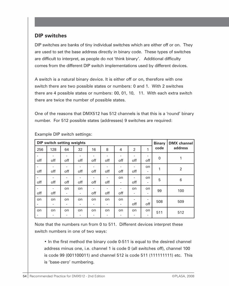
54 Recommended Practice for DMX512 - 2nd Edition ©PLASA, 2008
DIP switches
DIP switches are banks of tiny individual switches which are either off or on. They
are used to set the base address directly in binary code. These types of switches
are difficult to interpret, as people do not ‘think binary’. Additional difficulty
comes from the different DIP switch implementations used by different devices.
A switch is a natural binary device. It is either off or on, therefore with one
switch there are two possible states or numbers: 0 and 1. With 2 switches
there are 4 possible states or numbers: 00, 01, 10, 11. With each extra switch
there are twice the number of possible states.
One of the reasons that DMX512 has 512 channels is that this is a ‘round’ binary
number. For 512 possible states (addresses) 9 switches are required:
Example DIP switch settings:
Note that the numbers run from 0 to 511. Different devices interpret these
switch numbers in one of two ways:
• In the first method the binary code 0-511 is equal to the desired channel
address minus one, i.e. channel 1 is code 0 (all switches off), channel 100
is code 99 (001100011) and channel 512 is code 511 (111111111) etc. This
is ‘base-zero’ numbering.
DIP switch setting weights
256 128 64 32 16 8 4 2 1
- - - - - - - - -off off off off off off off off off
- - - - - - - - onoff off off off off off off off -
- - - - - - on - onoff off off off off off - off -
- - on on - - - on onoff off - - off off off - -
on on on on on on on - -- - - - - - - off off
on on on on on on on on on- - - - - - - - -
Binarycode
0
1
5
99
508
511
DMX channeladdress
1
2
6
100
509
512
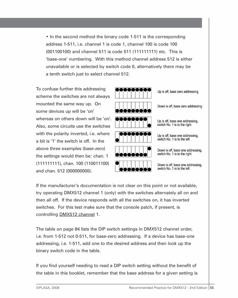
55Recommended Practice for DMX512 - 2nd Edition©PLASA, 2008
• In the second method the binary code 1-511 is the corresponding
address 1-511, i.e. channel 1 is code 1, channel 100 is code 100
(001100100) and channel 511 is code 511 (111111111) etc. This is
‘base-one’ numbering. With this method channel address 512 is either
unavailable or is selected by switch code 0, alternatively there may be
a tenth switch just to select channel 512.
To confuse further this addressing
scheme the switches are not always
mounted the same way up. On
some devices up will be ‘on’
whereas on others down will be ‘on’.
Also, some circuits use the switches
with the polarity inverted, i.e. where
a bit is ‘1’ the switch is off. In the
above three examples (base-zero)
the settings would then be: chan. 1
(111111111), chan. 100 (110011100)
and chan. 512 (000000000).
If the manufacturer’s documentation is not clear on this point or not available,
try operating DMX512 channel 1 (only) with the switches alternately all on and
then all off. If the device responds with all the switches on, it has inverted
switches. For this test make sure that the console patch, if present, is
controlling DMX512 channel 1.
The table on page 84 lists the DIP switch settings in DMX512 channel order,
i.e. from 1-512 not 0-511, for base-zero addressing. If a device has base-one
addressing, i.e. 1-511, add one to the desired address and then look up the
binary switch code in the table.
If you find yourself needing to read a DIP switch setting without the benefit of
the table in this booklet, remember that the base address for a given setting is
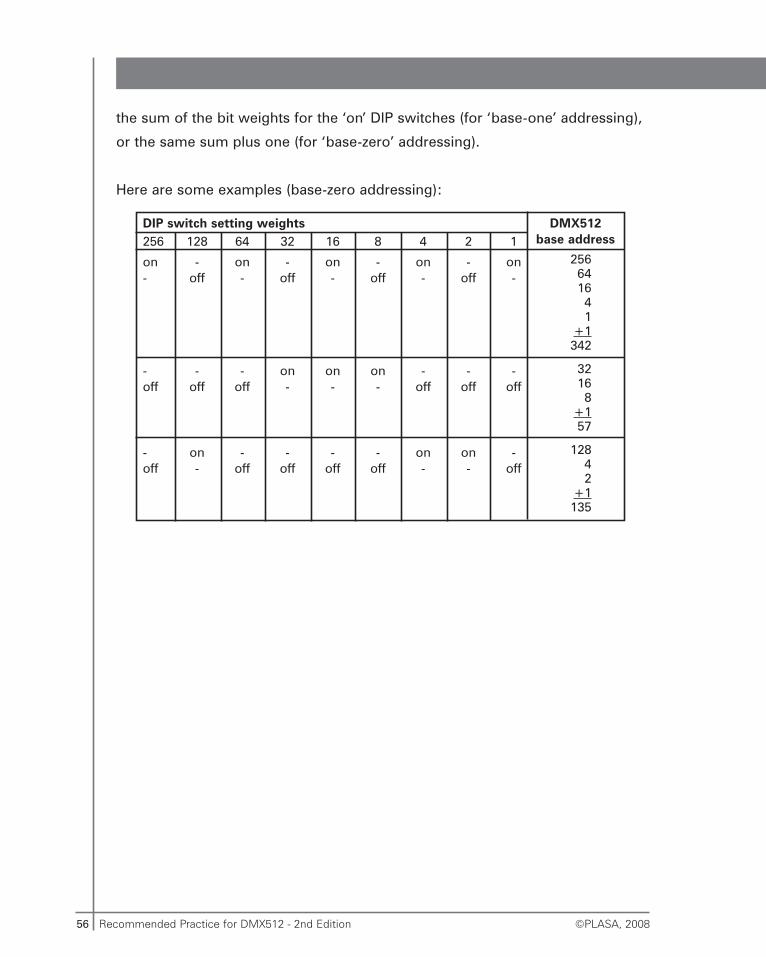
56 Recommended Practice for DMX512 - 2nd Edition ©PLASA, 2008
the sum of the bit weights for the ‘on’ DIP switches (for ‘base-one’ addressing),
or the same sum plus one (for ‘base-zero’ addressing).
Here are some examples (base-zero addressing):
DIP switch setting weights256 128 64 32 16 8 4 2 1
on - on - on - on - on- off - off - off - off -
- - - on on on - - -off off off - - - off off off
- on - - - - on on -off - off off off off - - off
DMX512base address
256641641
+1342
32168
+157
12842
+1135
57Recommended Practice for DMX512 - 2nd Edition©PLASA, 2008
Address offsets for multiple DMX512 lines
When a system comprises more than 512 receiving device channels, additional
DMX512 lines are employed. Thus a console with 1024 output channels will be
fitted with two DMX512 output ports, one with 1536 output channels will be
fitted with three DMX512 output ports, and so on.
Each of these 512 channel ports are also known as ‘DMX universes’ each with
1-512 channels. Receivers, however, in most cases have only one input port,
with addressing selectable in the range 1-512. In order to set a device to
respond to, say, console output channel 1200 it is necessary to connect to
console port 3 and set the address to 1200-512-512 = 176, universe 3.
The table on page 89 lists the relationship between sequentially numbered
DMX512 channels, as they would appear on the console, and universe
numbered channels in blocks of 512, as they would appear on a receiving
device.
These tables assume that each port on a multi-port console outputs a full 512
channels.
For instance, if a system comprises two 480 way dimming systems, each with
one DMX512 input, it is not possible to patch the second system to console
output channels 481-960 since these straddle the two outputs. The solution is
to connect the second system to the second DMX universe from the console
and then patch it to channels 513-992. This leaves channels 481-512
unpatched.
Some consoles allow the user to define the number of channels on a DMX512
output port in order to match this to the number of devices and thus to achieve
a continuously numbered patch without any gaps.
58 Recommended Practice for DMX512 - 2nd Edition ©PLASA, 2008
RDM functions
RDM overview
RDM operates on the same signalling wires as normal DMX. During an RDM
transaction the sending of normal level data is momentarily suspended. The
RDM controller typically sends a special packet of data to an RDM responder
(a device) instructing it to respond. Devices are identified for RDM
independently of their normal, user set, DMX address. If a device receives an
instruction to respond it is allowed to take control of the DMX line and transmit
its information. RDM messages are much shorter than typical DMX level
messages so that their use does not unduly impact the update speed (refresh
rate) of normal DMX.
In some circumstances RDM activity during a show may cause perceptible
delays. It is recommended to disable RDM during a show if the maximum
possible DMX update rate is required for smooth operation.
Because RDM uses a separate unique identifying scheme it provides the
possibility to remotely set the normal user DMX address. This is a major
benefit of RDM as it allows equipment to be addressed in inaccessible locations
or not to be provided with a user-settable addressing switch or interface at all.
The details of all the features of RDM are outside the scope of this small
booklet. Below are shown a simplified explanation of how remote addressing
works and a list of the basic message types. Readers wishing to learn more
should read the full ANSI E1.11-2008 (USITT DMX512-A) and ANSI E1.20-2010
(DMX-RDM) specifications.
The advice given here on cabling, connectors, network topology and
in-line processing equipment allows users and installers to set up
a DMX system capable of supporting RDM.
59Recommended Practice for DMX512 - 2nd Edition©PLASA, 2008
RDM addressing process
All RDM equipment contains a unique identifying number, known as its UID,
permanently coded into its electronics. The number is arranged in two parts,
manufacturer I.D. and a serial number. These numbers may not be altered by
the user, and normally may not be altered at all.
The unique identifier provides a way to send commands to individual devices
regardless of their DMX address, which may be wrong or shared by another
device.
The RDM Standard defines how an RDM Controller can discover the UIDs of all
attached RDM Responder devices. The method is rather ingenious and requires
no prior list of UIDs.
Discovery
Discovery is a multi-step process that takes some time to complete. Normally
discovery should be run prior to a show and not during one.
Discovery is a detailed procedure outside the scope of this booklet. What
follows is a simplified description to illustrate the basic process:
• For the first bit in the UID the RDM controller sends a message “Do you
have this bit set in your UID?” to all RDM responders. Any and all devices
with that bit set respond. If there is no response then the controller knows
that there are no devices with that bit set.
• Next it asks the question “Do you have the next bit in the UID set” Again
any and all devices with that bit set respond.
• Eventually when all the bits have been tested the controller can know for
certain about the UID of one device (and one only), which combination of
ID bits was found to be set. Now it tells that one specific device to shut-up
and not respond for the time being to any more discovery requests.
60 Recommended Practice for DMX512 - 2nd Edition ©PLASA, 2008
• Now that one device has been eliminated the discovery can continue
until another unique device is discovered, and told to shut-up.
• Eventually when the last device is found and told to shut-up further
discovery requests will produce no answer. At this point the controller
knows it has found all the devices, and it knows the unique identifying
number of each one.
• Now the controller can tell all the devices to wake up and respond each
to their own unique UID. Discovery is complete and from now on
messages are only sent to specific devices.
Discovering RDM Unique Identifying Numbers can take a variable
amount of time depending on the range of UID bits in use. In
extreme cases many messages may be required to find all devices.
The Discovery process is more disruptive to normal DMX level
transmissions than other RDM transactions. The sending of discovery
messages during a show, interspersed with normal DMX levels,
should be avoided unless necessary as it may affect the perceived
refresh rate and stability of fades and device movement. If it may be
beneficial to operate Discovery during a show you should test the
behaviour beforehand and verify that the reduction in throughput of
level data is acceptable.
RDM Messaging
Apart from device discovery which is a special case, most RDM messages are
sent to specific devices by means of the RDM unique identifying number.
Because the devices may now be directly addressed by the controller the
controller may use this to remotely set the device’s normal DMX address, the
address to which it will respond for normal DMX level data. Thus it is now
possible to set up the DMX addressing of an RDM system without going
anywhere near the devices themselves. They may be located in inaccessible
61Recommended Practice for DMX512 - 2nd Edition©PLASA, 2008
places, including permanently buried in the ground or embedded in a structure,
or more simply on a lighting bar above scenery, out of reach from a ladder.
If a device is RDM capable it does not necessarily mean that its DMX
address may be remotely set. RDM makes this possible but does not
guarantee that the manufacturer has chosen to implement that
feature of RDM. Check with the manufacturer to see what specific
RDM features are possible with a given device.
Device identification
When using RDM to set the normal DMX address of a device it is very helpful to
know which device is which. The RDM unique identifying number says nothing
about where the device is located.
An RDM command is provided for a device to identify itself in a visible way.
For luminaires this identification is usually simply to flash the lamp on. For
a non-illuminating device, say a moving mirror, the device can move around.
Many controllers incorporate the use of the Device Identification command into
the process of setting the DMX address so that the user may simply advance
from one device to the next and set the required DMX address.
Getting and Setting device properties
The DMX-RDM Standard defines a great many other messages that may be sent
to and received from devices. Full details are to be found in the original ANSI
E1.20-2010 (DMX-RDM) Standard. Here follows a list of the currently supported
message types.
The general method is for the console to issue a “get property” or “set
property” message. ‘Get’ messages demand a response, such as “what is your
temperature?” ‘Set’ messages do not normally solicit a response, such as
“Invert the Pan value”.

62 Recommended Practice for DMX512 - 2nd Edition ©PLASA, 2008
Devices never send any messages unless told to by an RDM
controller.
Occasionally a device may not be able to answer, in which case it
responds with “I cannot answer now, ask me again later”
RDM message types
• RDM Information Messages
• Product Information Messages
• DMX512 Setup Messages
• Sensor Parameter Messages
• Power/Lamp Setting Parameter Messages
• Display Setting Parameter Messages
• Device Configuration Parameter Messages
• Device Control Parameter Messages
For full details of the format and function of these messages please read the
ANSI E1.20-2010 (RDM) Standard.
63Recommended Practice for DMX512 - 2nd Edition©PLASA, 2008
Fault Finding
DMX512 faults can be quite difficult to analyse, mostly due to the system’s
relatively high speed. It is difficult to trigger an oscilloscope from the DMX512
line and to be sure of what is being observed. There are, however, some
simple tests that can be carried out with a basic multimeter which will show up
many common problems.
The results of these tests will depend on the type of console, the type of
multimeter and the termination resistance value. It is a good idea to make
these measurements on your system when it is fully working and then to keep
a note of the readings and the type of instrument used to make them. If there
is a fault in the future it may be possible to identify the problem by simple
comparison of the readings. The same type of multimeter should be used as
for the original tests.
Voltage Tests
With the console and all the devices connected together measure the d.c.
voltages between pins 2 and 3 (multimeter negative to pin 2) under the
following conditions:
All DMX512 channels at zero (off); the meter should read low or negative
voltage
All DMX512 channels at full; the voltage should increase but it may still be
negative if the Break is very long and there are few channels on the link.
Although the measurements have no absolute meaning there should be
a noticeable change of voltage. Make sure that all channels are set to either
full or off, i.e. that there is no partial patch in the console causing only some
DMX512 output channels to be affected.
For this test an analog, moving coil, meter may give more consistent readings
as it will naturally average the digital data signals. Some digital meters may
64 Recommended Practice for DMX512 - 2nd Edition ©PLASA, 2008
give unpredictable and un-repeatable readings. A good place to take the
measurements is across the terminator resistor, particularly if this is the ‘dummy
plug’ type.
Repeat the readings for pins 1 to 2 and pins 1 to 3 (multimeter negative to pin
1) and make a note of the ‘normal’ values. The pin 1 - 3 readings should
behave like the first test, i.e. an increase in level corresponds to an increase in
voltage. The pin 1 - 2 test will be inverted, i.e. an increase in level should
produce a decrease in voltage
Common-mode voltage tests
These tests will determine if a common-mode voltage problem exists between
the DMX512 network and a receiving device. Set the voltmeter to d.c. and
disconnect the receiver from the line. Measure the voltage between the line pin
1 and the receiver pin 1. If the reading is 7V or greater there is an unacceptable
common-mode voltage. Repeat the readings with the meter set to read a.c.
volts. A reading of approx. 5V or more also indicates excess common-mode
voltage. Unless it is possible to re-arrange the grounding to eliminate the
voltage it will be necessary to use an opto-isolated repeater/splitter between the
network and any devices exhibiting the above problem. Note that this may be
necessary in a number of different parts of the network as receivers may suffer
common-mode voltage not only with the console but also between themselves.
As common-mode voltage is influenced by the amount of current flowing in the
entire power system these measurements should be carried out with the
system running a typical variety of heavily loaded dimmers and the building
systems that consume significant power, such as air conditioning, elevators,
kitchens, heating and IT systems, running normally. Some experimentation
may be required in order to find the worst-case common-mode voltages.
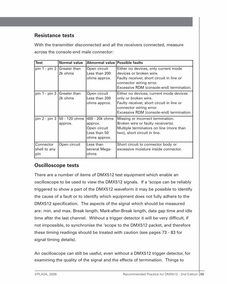
65Recommended Practice for DMX512 - 2nd Edition©PLASA, 2008
Resistance tests
With the transmitter disconnected and all the receivers connected, measure
across the console-end male connector:
Oscilloscope tests
There are a number of items of DMX512 test equipment which enable an
oscilloscope to be used to view the DMX512 signals. If a ‘scope can be reliably
triggered to show a part of the DMX512 waveform it may be possible to identify
the cause of a fault or to identify which equipment does not fully adhere to the
DMX512 specification. The aspects of the signal which should be measured
are: min. and max. Break length, Mark-after-Break length, data gap time and idle
time after the last channel. Without a trigger detector it will be very difficult, if
not impossible, to synchronise the ‘scope to the DMX512 packet, and therefore
these timing readings should be treated with caution (see pages 73 - 83 for
signal timing details).
An oscilloscope can still be useful, even without a DMX512 trigger detector, for
examining the quality of the signal and the effects of termination. Things to
Test Normal value Abnormal value Possible faults
pin 1 - pin 2 Greater than2k ohms
Open circuitLess than 200ohms approx.
Either no devices, only current modedevices or broken wire.Faulty receiver, short circuit in line orconnector wiring error.Excessive RDM (console-end) termination.
pin 1 - pin 3 Greater than2k ohms
Open circuitLess than 200ohms approx.
Either no devices, current mode devicesonly or broken wire.Faulty receiver, short circuit in line orconnector wiring error.Excessive RDM (console-end) termination.
pin 2 - pin 3 50 - 120 ohmsapprox.
400 - 20k ohmsapprox.Open circuitLess than 50ohms approx.
Missing or incorrect termination.Broken wire or faulty receiver(s).Multiple terminators on line (more thantwo), short circuit in line.
Connectorshell to anypin
Open circuit Less thanseveral Mega-ohms
Short circuit to connector body orexcessive moisture inside connector.
66 Recommended Practice for DMX512 - 2nd Edition ©PLASA, 2008
look for are: high frequency noise, low frequency noise (superimposed mains,
50 or 60Hz), distortion of the square edges of the signal and insufficient voltage
at the far end of cable. Signal reflections will be more difficult to observe
unless the ‘scope has a very stable trigger.
An oscilloscope is useful, even if it cannot be triggered reliably, or at all, to
prove that the two data lines are carrying complementary signals, i.e. one
inverted with respect to the other. Often the only way to prove this for certain
is with a 2-trace oscilloscope.
If, for instance, the data + wire is broken, when a voltage measurement is made
at the far end of a cable, the data plus (pin 3) line will display a voltage with
respect to the common (shield) connection that is in fact the data minus (pin 2)
voltage passing through the termination resistor.
A 2-trace ‘scope should be connected as follows:
Common to pin 1, trace A to pin 2 and trace B to pin 3. It should be possible to
verify that the two traces carry the same signal but with one of them inverted
with respect to the other.
Specialised DMX512 test equipment
There is a wide variety of DMX512 test equipment now available which can be
used to analyse DMX512 signals, identify faults and generate reference signals.
Such instruments can:
• Display a range of levels
• Flash dimmers for testing
• Display input timings and variations
• Adjust output timings
• Trigger logic analysers and oscilloscopes
• Modify or filter start-codes
• Generate reference DMX512 packets at the fastest rates
67Recommended Practice for DMX512 - 2nd Edition©PLASA, 2008
Manufacturers and system designers should make the maximum use of this
equipment in order to ensure that their products conform within all the limits of
the DMX512-A specification.
Fault Finding Checklist
Most DMX512 faults are due to incorrect termination, faulty wiring or ground-
loop effects. Before embarking on a complex set of tests always check these
simple things:
• Are there too many devices on the line? This could be the case if some
of them are DOL isolating receivers, otherwise up to 32 standard EIA-485
receivers are allowed.
• Is the line terminated, at both ends, with approximately 120 ohms?
• Are all the conductors connected at both ends of the cable? DMX512
has an annoying tendency to work intermittently even if the inverted-data
wire is cut (pin 2) or the shield is not connected (pin 1), or these two pins
are shorted together.
• Are the inverted-data (pin 2) and signal common (shield) connections
swapped? DMX will often work intermittently with these wires
interchanged.
• Is one of the data signals missing? This may cause random flickering in
addition to apparent normal operation.
• Does the introduction of an opto-isolator in the network clear-up or
reduce the problem? If so, there is probably a ground-loop effect. It may
be possible to re-route the power cabling in such a way as to minimise this
effect. Otherwise, it may be necessary to introduce opto-isolation to some
branches of, or all of, the DMX512 network. Do not rely on a splitter to
isolate just one DMX line from others; most splitters have an isolated input
but the multiple outputs are usually not isolated from each other. To prove
or disprove problems related to ground-loops you must isolate each line
independently, one-at-a-time.
68 Recommended Practice for DMX512 - 2nd Edition ©PLASA, 2008
The EIA-485 (RS-485) communications spec.
DMX512 is designed to connect with cables via an industry stan-dard interface
called EIA-485 (commonly referred to as RS-485). EIA-485 is only a description
of the electrical level of the interface, the voltages, currents and i.c. devices.
It would be possible to connect a DMX512 device to another EIA-485 device,
e.g. a computer or machine, with no damage. However, the signals would be
meaningless, except to another DMX512 device.
EIA-485 specifies that the connection between transmitter and receiver is
achieved with two or three wires: a data wire, an inverted data wire and, often,
a ground/return/0V wire. The two data wires are twisted together and enclosed
in a metal shield formed by the 0V wire. This helps to eliminate magnetic hum
pick-up and interference.
Data is sent as a series of high and low levels on the line. The line is
considered high when the data wire is positive with respect to the inverted data
wire. The line is considered low when the data wire is negative with respect to
the inverted data wire. In some systems the 0V wire is only required as a shield
and is not connected to the receiver circuitry (see page 33, Network Isolation).
This method of sending the signal on one wire and sending the opposite, or
complement, signal on another wire is known as ‘balanced’ transmission. The
receiver detects the difference between the data wire and the inverted data wire
in order to decode the signal. Any interference picked up by the cable will
almost certainly affect both data wires equally and will therefore be ignored by
the receiver.
The wires are twisted together in order to ensure that any extraneous signals
are picked up by both data wires. This twisting is the most important measure
to reduce interference and is more effective than the cable shield. For this
reason it is not recommended to use a normal twin shielded cable as many of
these cables, e.g. for audio or general use, do not have the conductors twisted
together.
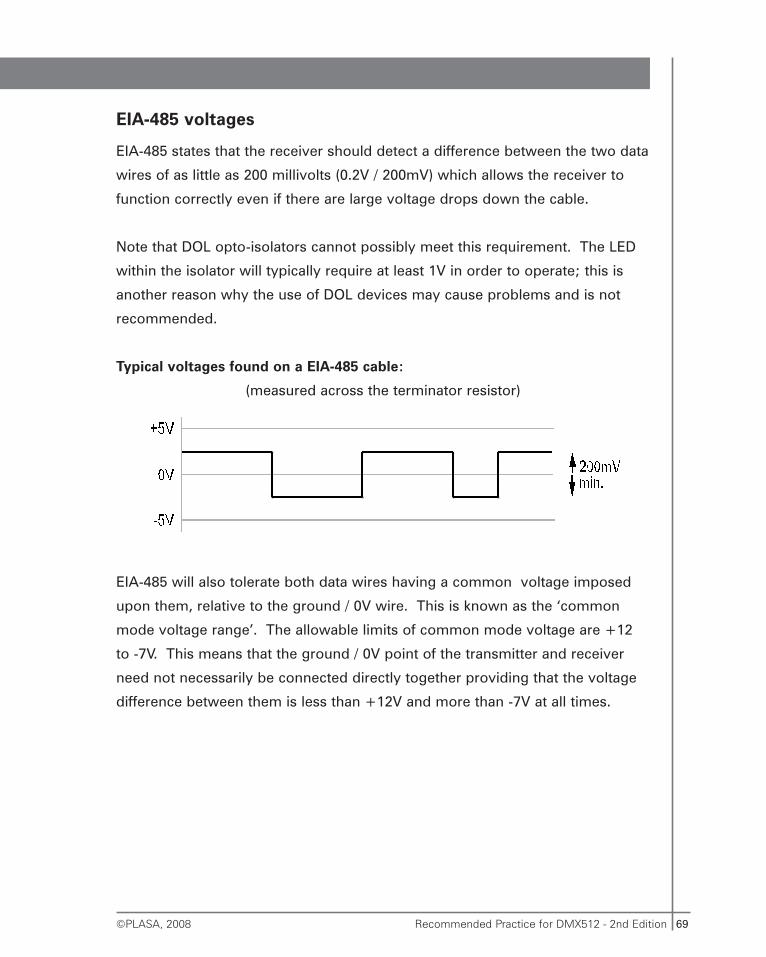
69Recommended Practice for DMX512 - 2nd Edition©PLASA, 2008
EIA-485 voltages
EIA-485 states that the receiver should detect a difference between the two data
wires of as little as 200 millivolts (0.2V / 200mV) which allows the receiver to
function correctly even if there are large voltage drops down the cable.
Note that DOL opto-isolators cannot possibly meet this requirement. The LED
within the isolator will typically require at least 1V in order to operate; this is
another reason why the use of DOL devices may cause problems and is not
recommended.
Typical voltages found on a EIA-485 cable:
(measured across the terminator resistor)
EIA-485 will also tolerate both data wires having a common voltage imposed
upon them, relative to the ground / 0V wire. This is known as the ‘common
mode voltage range’. The allowable limits of common mode voltage are +12
to -7V. This means that the ground / 0V point of the transmitter and receiver
need not necessarily be connected directly together providing that the voltage
difference between them is less than +12V and more than -7V at all times.
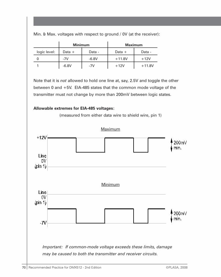
70 Recommended Practice for DMX512 - 2nd Edition ©PLASA, 2008
Min. & Max. voltages with respect to ground / 0V (at the receiver):
Minimum Maximum
logic level: Data + Data - Data + Data -
0 -7V -6.8V +11.8V +12V
1 -6.8V -7V +12V +11.8V
Note that it is not allowed to hold one line at, say, 2.5V and toggle the other
between 0 and +5V. EIA-485 states that the common mode voltage of the
transmitter must not change by more than 200mV between logic states.
Allowable extremes for EIA-485 voltages:
(measured from either data wire to shield wire, pin 1)
Maximum
Minimum
Important: If common-mode voltage exceeds these limits, damage
may be caused to both the transmitter and receiver circuits.
71Recommended Practice for DMX512 - 2nd Edition©PLASA, 2008
Bits & Bytes
EIA-485 (RS-485) describes the physical level but not the meaning of the
signals. DMX512 describes the signals in fair detail but still with some room to
manoeuvre. This flexibility allows for different design solutions to meet
different needs and budgets. For instance, DMX512 is not limited to exactly 512
channels, as the name suggests. If fewer channels are sufficient, the standard
permits the use of a lower last-channel number.
The basic element of any communications protocol is a set of codes. Each
code is a unique series of high and low signals on the line, called bits. The bits
are sent out at predetermined time intervals which for DMX512 is every 4
microseconds (4μs). In DMX512 each code is 8 bits long and is called a byte.
The 8 bits in a byte allow 256 different bit combinations or codes which allows
the choice of 256 levels - from 0 to 255 (full). See page 94 for code conversion
table and note about conversion inaccuracies.
In addition to the bits in a byte it is necessary to mark where the byte begins
and ends so that the receiver can synchronise with the signal. For this purpose
three more bits are added to the byte. They are a start bit (low) and two stop
bits (high).
When the line is not sending any information it rests or ‘idles’ in the high state.
When a byte is sent the start bit instructs the receiver to start reading the
remaining bits at 4μs intervals until 8 bits have been read. The receiver then
expects the line to go high for two bit periods for the stop bits. At the end of
the second stop bit the line can either idle, (it is already high so this means do
nothing) or a new start bit can initiate another byte transfer.
Thus there are 11 bits in total for each byte that is sent, 4μs x 11 = 44μs per
byte. These 11 bit codes are called ‘slots’.
Note that in the previous edition these were known as frames. Here the term
slot is preferred so as to be the same term as in the ANSI Standard.
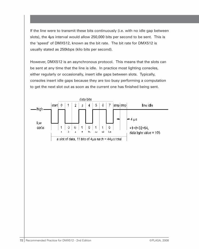
72 Recommended Practice for DMX512 - 2nd Edition ©PLASA, 2008
If the line were to transmit these bits continuously (i.e. with no idle gap between
slots), the 4μs interval would allow 250,000 bits per second to be sent. This is
the ‘speed’ of DMX512, known as the bit rate. The bit rate for DMX512 is
usually stated as 250kbps (kilo bits per second).
However, DMX512 is an asynchronous protocol. This means that the slots can
be sent at any time that the line is idle. In practice most lighting consoles,
either regularly or occasionally, insert idle gaps between slots. Typically,
consoles insert idle gaps because they are too busy performing a computation
to get the next slot out as soon as the current one has finished being sent.
73Recommended Practice for DMX512 - 2nd Edition©PLASA, 2008
The DMX512 packet
DMX512 supports up to 512 channels of data which are sent out sequentially
from channel 1 to the highest numbered channel available from the console.
Although technically possible, the DMX512 standard does not allow for more
than 512 channels to be transmitted on the link. Some types of analog to DMX
converters may be chained together until the number of transmitted channels
exceeds 512.
The use of more than 512 channels on a DMX512 link is not part of
the DMX standards and may cause problems with some receiving
devices.
Consoles providing more than 512 dimmer outputs are fitted with two or more
DMX512 outlets (see page 89). DMX512 data slots should not be confused with
console channels or dimmer channels. When patching is present a console
channel could affect several DMX512 slots, or none. DMX512 slots could then
in turn be patched (in the dimmer or an in-line patching computer) to several
dimmers, or none.
First follows a description of a ‘normal’ DMX512 packet, such as used in the
original specification or used in DMX512-A when no RDM functions are running.
Below that is a description of the RDM formatted packets.
Regular DMX512 ‘levels only’ packet
Break
In order that the receiver can identify which is DMX data slot 1, the line is set to
a special condition known as ‘Break’ (remember that all 256 possible codes are
used for level information). The Break condition is a continuous low signal on
the line for at least 92μs (two complete slots, i.e. two bytes each including start
& stop bits, plus 4μs). This signals to the receiver that the following information
is the start of a new ‘packet’ of data levels.
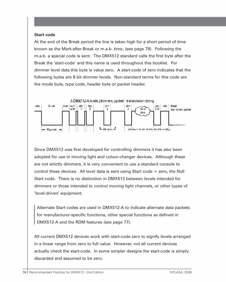
74 Recommended Practice for DMX512 - 2nd Edition ©PLASA, 2008
Start code
At the end of the Break period the line is taken high for a short period of time
known as the Mark-after-Break or m.a.b. time, (see page 79). Following the
m.a.b. a special code is sent. The DMX512 standard calls the first byte after the
Break the ‘start-code’ and this name is used throughout this booklet. For
dimmer level data this byte is value zero. A start-code of zero indicates that the
following bytes are 8 bit dimmer levels. Non-standard terms for this code are
the mode byte, type code, header byte or packet header.
Since DMX512 was first developed for controlling dimmers it has also been
adopted for use in moving light and colour-changer devices. Although these
are not strictly dimmers, it is very convenient to use a standard console to
control these devices. All level data is sent using Start code = zero, the Null
Start code. There is no distinction in DMX512 between levels intended for
dimmers or those intended to control moving light channels, or other types of
‘level-driven’ equipment.
Alternate Start codes are used in DMX512-A to indicate alternate data packets
for manufacturer-specific functions, other special functions as defined in
DMX512-A and the RDM features (see page 77).
All current DMX512 devices work with start-code zero to signify levels arranged
in a linear range from zero to full value. However, not all current devices
actually check the start-code. In some simpler designs the start-code is simply
discarded and assumed to be zero.
75Recommended Practice for DMX512 - 2nd Edition©PLASA, 2008
Devices which do not check the start-code will have problems with
consoles that send any other start-codes and will not function, or will
malfunction, with RDM features running.
Refresh rate
The refresh rate is the number of packets sent per second. Because DMX512
allows gaps between slots and only specifies the minimum Break time the
refresh rate can be very different between different makes of console. The
maximum possible refresh rate also depends on the number of channels being
sent.
Continuous refresh
Since the 1st edition of this booklet was written in 1994, the processing power
of even the simplest low-cost microprocessors has increased by orders of
magnitude. The task of sending and receiving DMX was originally quite
onerous and resulted in less than the maximum possible refresh rate being
produced in many cases. Today it has become trivial to output continuous
DMX at the maximum possible rate. This can occasionally cause problems with
older receiving equipment. Some manufacturers offer settings to reduce the
rate that DMX packets are sent to try to alleviate system incompatibilities.
However, many transmitter designs use a method known as DMA (direct
memory access) which sends the bytes independently of the microprocessor
software. DMA-based transmissions cannot be slowed down; they always
occur at the maximum possible rate, with no gaps between bytes. The only
solution for receivers unable to cope with DMA DMX rates is to introduce
another in-line device that reads in DMX and can be set to transmit it at a lower
refresh rate.
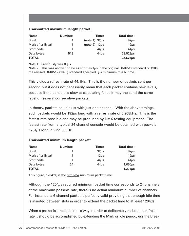
76 Recommended Practice for DMX512 - 2nd Edition ©PLASA, 2008
Transmitted maximum length packet:
Name: Number: Time: Total time:Break 1 (note 1) 92μs 92μsMark-after-Break 1 (note 2) 12μs 12μsStart-code 1 44μs 44μsData bytes 512 44μs 22,528μsTOTAL 22,676μs
Note 1: Previously was 88μsNote 2: This was allowed to be as short as 4μs in the original DMX512 standard of 1986,the revised DMX512 (1990) standard specified 8μs minimum m.a.b. time.
This yields a refresh rate of 44.1Hz. This is the number of packets sent per
second but it does not necessarily mean that each packet contains new levels,
because if the console is slow at calculating fades it may the send the same
level on several consecutive packets.
In theory, packets could exist with just one channel. With the above timings,
such packets would be 192μs long with a refresh rate of 5.208kHz. This is the
fastest rate possible and may be produced by DMX testing equipment. The
fastest rate from a typical 24 channel console would be obtained with packets
1204μs long, giving 830Hz.
Transmitted minimum length packet:
Name: Number: Time: Total time:Break 1 92μs 92μsMark-after-Break 1 12μs 12μsStart-code 1 44μs 44μsData bytes 24 44μs 1,056μsTOTAL 1,204μs
This figure, 1204μs, is the required minimum packet time.
Although the 1204μs required minimum packet time corresponds to 24 channels
at the maximum possible rate, there is no actual minimum number of channels.
For instance, a 6 channel packet is perfectly valid providing that enough idle time
is inserted between slots in order to extend the packet time to at least 1204μs.
When a packet is stretched in this way in order to deliberately reduce the refresh
rate it should be accomplished by extending the Mark or idle period, not the Break
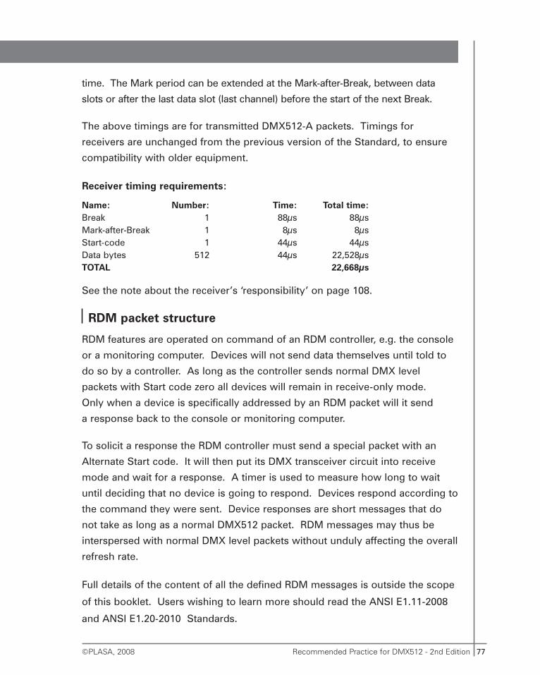
77Recommended Practice for DMX512 - 2nd Edition©PLASA, 2008
time. The Mark period can be extended at the Mark-after-Break, between data
slots or after the last data slot (last channel) before the start of the next Break.
The above timings are for transmitted DMX512-A packets. Timings for
receivers are unchanged from the previous version of the Standard, to ensure
compatibility with older equipment.
Receiver timing requirements:
Name: Number: Time: Total time:Break 1 88μs 88μsMark-after-Break 1 8μs 8μsStart-code 1 44μs 44μsData bytes 512 44μs 22,528μsTOTAL 22,668μs
See the note about the receiver’s ‘responsibility’ on page 108.
RDM packet structure
RDM features are operated on command of an RDM controller, e.g. the console
or a monitoring computer. Devices will not send data themselves until told to
do so by a controller. As long as the controller sends normal DMX level
packets with Start code zero all devices will remain in receive-only mode.
Only when a device is specifically addressed by an RDM packet will it send
a response back to the console or monitoring computer.
To solicit a response the RDM controller must send a special packet with an
Alternate Start code. It will then put its DMX transceiver circuit into receive
mode and wait for a response. A timer is used to measure how long to wait
until deciding that no device is going to respond. Devices respond according to
the command they were sent. Device responses are short messages that do
not take as long as a normal DMX512 packet. RDM messages may thus be
interspersed with normal DMX level packets without unduly affecting the overall
refresh rate.
Full details of the content of all the defined RDM messages is outside the scope
of this booklet. Users wishing to learn more should read the ANSI E1.11-2008
and ANSI E1.20-2010 Standards.
78 Recommended Practice for DMX512 - 2nd Edition ©PLASA, 2008
Signal timings
The DMX512-A specification has slightly changed the timing specification from
the previous (DMX512/1990) version of the Standard
A few timings are altered to allow operation of DMX-RDM; in particular the
timings of Break and Mark-after-Break are now different between transmitters
and receivers. Receivers must still be able to respond to the original timing but
transmitters must send a longer minimum Break and longer minimum m.a.b.
Some consoles, and other DMX512 transmitters, allow the user to set up the
output timing, or to choose from a number of different timing ‘flavours’. This
can be useful when there are devices connected which are not fully compliant
with the DMX512 specification and are unable to receive DMX512 at the
maximum possible speed. This has been a problem with early designs of
dimmers, moving lights and colour scroll changers.
Where problems exist it is often due to inadequate testing of the device for all
the valid range of DMX512 timings. In the early days of DMX512 there were
few, if any, consoles capable of transmitting DMX512 at the maximum possible
rate and so receivers built then may have functioned perfectly well. With the
availability of fast microprocessors most modern designs can transmit at, or
near to, the maximum possible rate and so the user can experience problems
with older devices.
It is natural for the user to assume that problems experienced when a new
console fails to control a system properly are due to the new console. This is
rarely the case.
It should be emphasised that a truly compliant DMX512 design should
work with any other DMX512 equipment. Indeed this is crucial test of
a ‘Standard’.
What follows is some advice on how to best accommodate the timing
requirements of these ‘rogue’ devices.
79Recommended Practice for DMX512 - 2nd Edition©PLASA, 2008
Break timing
The Break length time is critical for certain devices. Although DMX512-A does
not specify a maximum length for Break, some devices are sensitive to the
Break length and can malfunction if the Break is too long. A Break length of
100μs to 200μs will overcome these problems.
Some devices may measure the Break length with a timing circuit to see if it
exceeds 88μs. If a DMX512(1990) transmitter is sending a Break of exactly
88μs, due to tolerances the receiver may decide that it is longer or shorter than
88μs. When the receiver decides that the Break is longer than, or equal to 88μs,
the packet will be accepted as a valid packet. When the receiver decides that
the Break is less than 88μs the packet will be discarded. Therefore transmitters
must always be set to produce a Break of at least 92μs.
In addition, some other devices actually detect a Break of as little as 38μs. This
is because the UART circuits in these devices detect byte code 0 with a missing
stop bit and interpret this as Break. However, this should not be a problem as
all DMX512 compliant transmitters generate two stop bits.
A DMX512 compliant receiving device should be able to detect
a Break of 88μs or greater.
Mark-after-Break timing
The Mark-after-Break time as specified in DMX512 has been a source of
difficulties for designers of DMX512 equipment. The original specification was
4μs min. m.a.b. time. For slower receivers this was not enough time to recover
from the Break and then catch the first byte (the start-code). In this case they
would probably catch the second byte instead (dimmer 1) and treat it as the
start-code. If dimmer 1 was at value 0 the receiver would use this as the start-
code for dimmer levels and then read in the following values, all offset by one
from their true channel number. As this phenomenon was erratic the dimmer
signals would appear to shuffle up and down between adjacent channels. If this
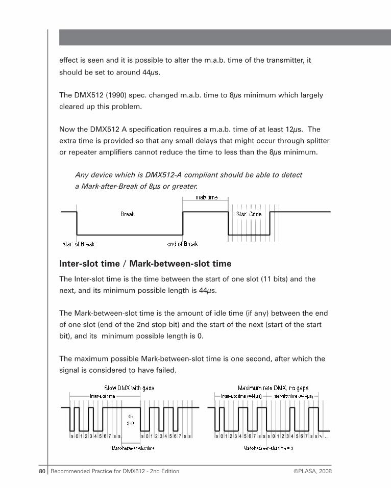
80 Recommended Practice for DMX512 - 2nd Edition ©PLASA, 2008
effect is seen and it is possible to alter the m.a.b. time of the transmitter, it
should be set to around 44μs.
The DMX512 (1990) spec. changed m.a.b. time to 8μs minimum which largely
cleared up this problem.
Now the DMX512 A specification requires a m.a.b. time of at least 12μs. The
extra time is provided so that any small delays that might occur through splitter
or repeater amplifiers cannot reduce the time to less than the 8μs minimum.
Any device which is DMX512-A compliant should be able to detect
a Mark-after-Break of 8μs or greater.
Inter-slot time / Mark-between-slot time
The Inter-slot time is the time between the start of one slot (11 bits) and the
next, and its minimum possible length is 44μs.
The Mark-between-slot time is the amount of idle time (if any) between the end
of one slot (end of the 2nd stop bit) and the start of the next (start of the start
bit), and its minimum possible length is 0.
The maximum possible Mark-between-slot time is one second, after which the
signal is considered to have failed.
81Recommended Practice for DMX512 - 2nd Edition©PLASA, 2008
Most consoles send data at somewhat less than the maximum possible rate,
particularly if they are performing a complex computation at the time. However
some consoles are able to do this, either continuously or in short bursts. This
can cause problems in some receivers.
If a device is unable to keep up with the signal it may occasionally drop
a channel, with all subsequent channels shifted down by one. This could
happen several times during the course of a packet, resulting in quite large
shifts for higher numbered channels.
If this effect is seen and the Inter-slot time can be adjusted, try setting it
between 55μs and 60μs. This solves most such problems without affecting the
refresh rate too severely. An Inter-slot time of 60μs with 512 channels per
packet produces a refresh rate of approximately 32Hz.
In much modern equipment this adjustment may not be technically possible
due to the method of transmitting using hardware in place of software (see
page 75).
Break-to-Break time
This is another term used to describe the refresh rate as the time between the
start of one packet to the start of the next. The refresh rate, in Hertz, is the
reciprocal of the Break-to-Break time, i.e.
The minimum Break-to-Break time is the required minimum packet time of
1204μs. The maximum Break-to-Break time is 1 second.
Loss of data tolerance
The DMX512 specification requires that devices retain their most recently
received levels for one second in the event of loss of data.
1
t(break—break) = Rate (Hz)
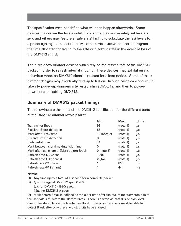
82 Recommended Practice for DMX512 - 2nd Edition ©PLASA, 2008
The specification does not define what will then happen afterwards. Some
devices may retain the levels indefinitely, some may immediately set levels to
zero and others may feature a ‘safe state’ facility to substitute the last levels for
a preset lighting state. Additionally, some devices allow the user to program
the time allocated for fading to the safe or blackout state in the event of loss of
the DMX512 signal.
There are a few dimmer designs which rely on the refresh rate of the DMX512
packet in order to refresh internal circuitry. These devices may exhibit erratic
behaviour when no DMX512 signal is present for a long period. Some of these
dimmer designs may eventually drift up to full-on. In such cases care should be
taken to power-up dimmers after establishing DMX512, and then to power-
down before disabling DMX512.
Summary of DMX512 packet timings
The following are the limits of the DMX512 specification for the different parts
of the DMX512 dimmer levels packet:
Min. Max. UnitsTransmitter Break 92 (note 1) μsReceiver Break detection 88 (note 1) μsMark-after-Break time 12 (note 2) (note 1) μsReceiver m.a.b detection 8 (note 1) μsSlot-to-slot time 44 (note 1) μsMark-between-slot time (inter-slot time) 0 (note 1) μsMark-after-last-channel (Mark-before-Break) 0 (note 3) (note 1) μsRefresh time (24 chans) 1,204 (note 1) μsRefresh time (512 chans) 22,676 (note 1) μsRefresh rate (24 chans) 1 830 HzRefresh rate (512 chans) 1 44 Hz
Notes:(1) Any time up to a total of 1 second for a complete packet.(2) 4μs for original DMX512 spec (1986).
8μs for DMX512 (1990) spec.12μs for DMX512 A spec.
(3) Mark-before Break is defined as the extra time after the two mandatory stop bits of the last data slot before the start of Break. There is always at least 8μs of high level, due to the stop bits, on the line before Break. Compliant receivers must be able to detect Break after only these two stop bits have elapsed.
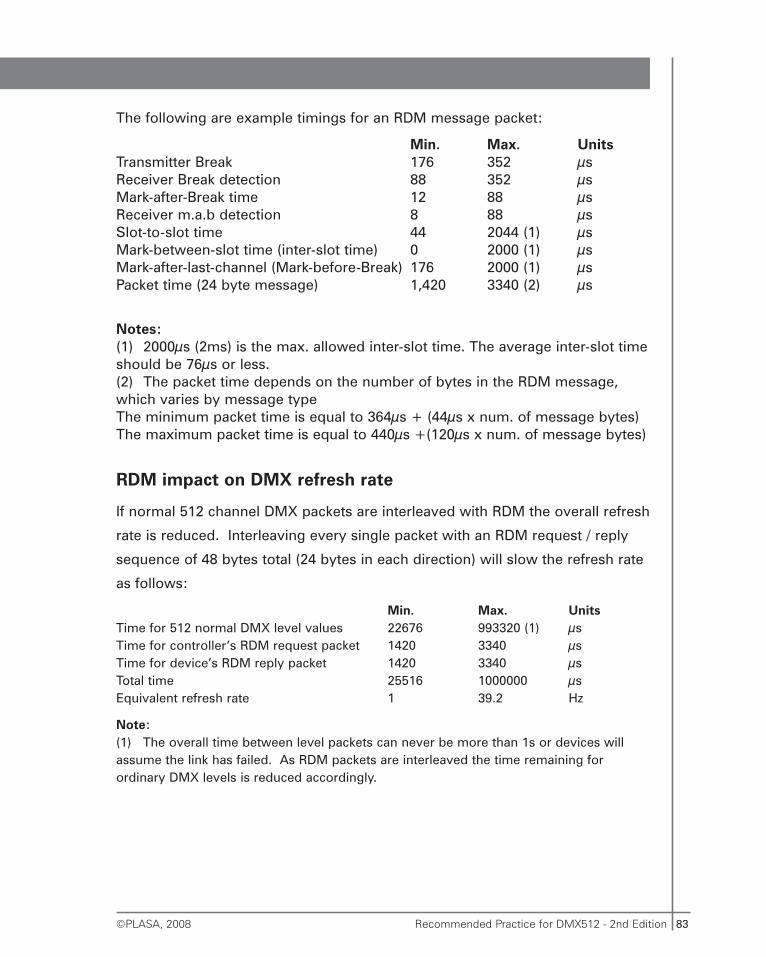
83Recommended Practice for DMX512 - 2nd Edition©PLASA, 2008
The following are example timings for an RDM message packet:
Min. Max. UnitsTransmitter Break 176 352 μsReceiver Break detection 88 352 μsMark-after-Break time 12 88 μsReceiver m.a.b detection 8 88 μsSlot-to-slot time 44 2044 (1) μsMark-between-slot time (inter-slot time) 0 2000 (1) μsMark-after-last-channel (Mark-before-Break) 176 2000 (1) μsPacket time (24 byte message) 1,420 3340 (2) μs
Notes:(1) 2000μs (2ms) is the max. allowed inter-slot time. The average inter-slot timeshould be 76μs or less.(2) The packet time depends on the number of bytes in the RDM message, which varies by message typeThe minimum packet time is equal to 364μs + (44μs x num. of message bytes)The maximum packet time is equal to 440μs +(120μs x num. of message bytes)
RDM impact on DMX refresh rate
If normal 512 channel DMX packets are interleaved with RDM the overall refresh
rate is reduced. Interleaving every single packet with an RDM request / reply
sequence of 48 bytes total (24 bytes in each direction) will slow the refresh rate
as follows:
Min. Max. UnitsTime for 512 normal DMX level values 22676 993320 (1) μsTime for controller’s RDM request packet 1420 3340 μsTime for device’s RDM reply packet 1420 3340 μsTotal time 25516 1000000 μsEquivalent refresh rate 1 39.2 Hz
Note:(1) The overall time between level packets can never be more than 1s or devices willassume the link has failed. As RDM packets are interleaved the time remaining forordinary DMX levels is reduced accordingly.
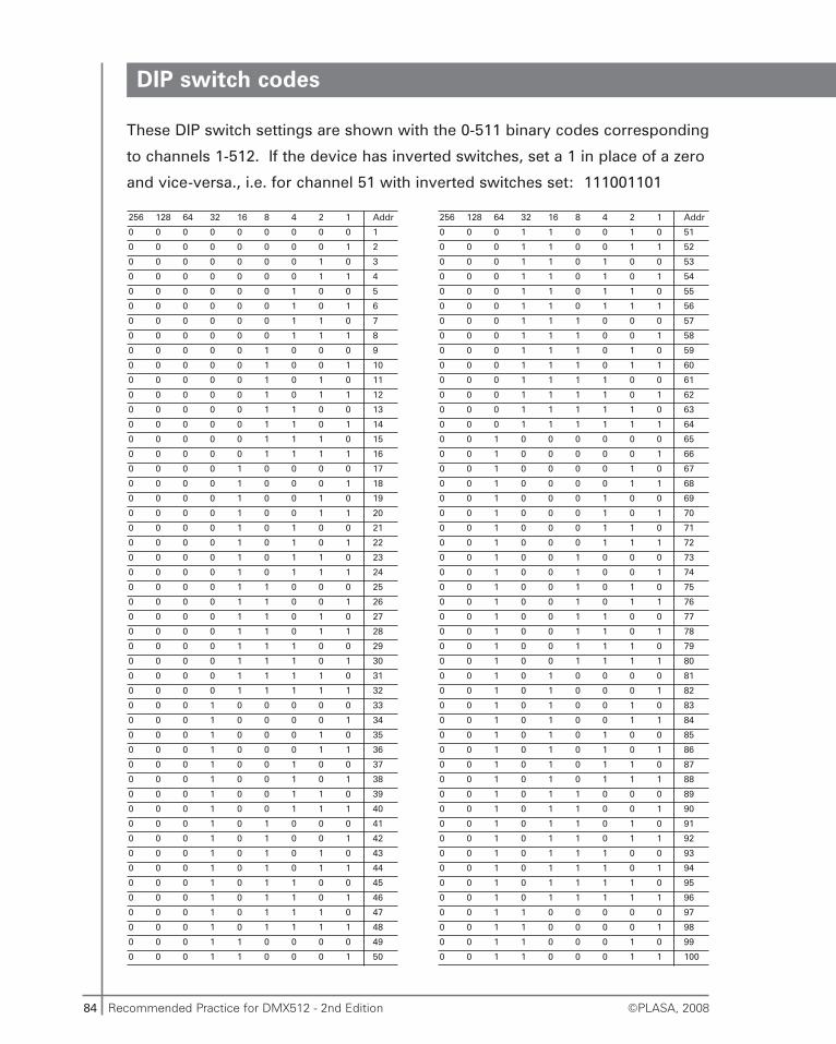
84 Recommended Practice for DMX512 - 2nd Edition ©PLASA, 2008
DIP switch codes
These DIP switch settings are shown with the 0-511 binary codes corresponding
to channels 1-512. If the device has inverted switches, set a 1 in place of a zero
and vice-versa., i.e. for channel 51 with inverted switches set: 111001101
256 128 64 32 16 8 4 2 1 Addr
0 0 0 0 0 0 0 0 0 1
0 0 0 0 0 0 0 0 1 2
0 0 0 0 0 0 0 1 0 3
0 0 0 0 0 0 0 1 1 4
0 0 0 0 0 0 1 0 0 5
0 0 0 0 0 0 1 0 1 6
0 0 0 0 0 0 1 1 0 7
0 0 0 0 0 0 1 1 1 8
0 0 0 0 0 1 0 0 0 9
0 0 0 0 0 1 0 0 1 10
0 0 0 0 0 1 0 1 0 11
0 0 0 0 0 1 0 1 1 12
0 0 0 0 0 1 1 0 0 13
0 0 0 0 0 1 1 0 1 14
0 0 0 0 0 1 1 1 0 15
0 0 0 0 0 1 1 1 1 16
0 0 0 0 1 0 0 0 0 17
0 0 0 0 1 0 0 0 1 18
0 0 0 0 1 0 0 1 0 19
0 0 0 0 1 0 0 1 1 20
0 0 0 0 1 0 1 0 0 21
0 0 0 0 1 0 1 0 1 22
0 0 0 0 1 0 1 1 0 23
0 0 0 0 1 0 1 1 1 24
0 0 0 0 1 1 0 0 0 25
0 0 0 0 1 1 0 0 1 26
0 0 0 0 1 1 0 1 0 27
0 0 0 0 1 1 0 1 1 28
0 0 0 0 1 1 1 0 0 29
0 0 0 0 1 1 1 0 1 30
0 0 0 0 1 1 1 1 0 31
0 0 0 0 1 1 1 1 1 32
0 0 0 1 0 0 0 0 0 33
0 0 0 1 0 0 0 0 1 34
0 0 0 1 0 0 0 1 0 35
0 0 0 1 0 0 0 1 1 36
0 0 0 1 0 0 1 0 0 37
0 0 0 1 0 0 1 0 1 38
0 0 0 1 0 0 1 1 0 39
0 0 0 1 0 0 1 1 1 40
0 0 0 1 0 1 0 0 0 41
0 0 0 1 0 1 0 0 1 42
0 0 0 1 0 1 0 1 0 43
0 0 0 1 0 1 0 1 1 44
0 0 0 1 0 1 1 0 0 45
0 0 0 1 0 1 1 0 1 46
0 0 0 1 0 1 1 1 0 47
0 0 0 1 0 1 1 1 1 48
0 0 0 1 1 0 0 0 0 49
0 0 0 1 1 0 0 0 1 50
256 128 64 32 16 8 4 2 1 Addr
0 0 0 1 1 0 0 1 0 51
0 0 0 1 1 0 0 1 1 52
0 0 0 1 1 0 1 0 0 53
0 0 0 1 1 0 1 0 1 54
0 0 0 1 1 0 1 1 0 55
0 0 0 1 1 0 1 1 1 56
0 0 0 1 1 1 0 0 0 57
0 0 0 1 1 1 0 0 1 58
0 0 0 1 1 1 0 1 0 59
0 0 0 1 1 1 0 1 1 60
0 0 0 1 1 1 1 0 0 61
0 0 0 1 1 1 1 0 1 62
0 0 0 1 1 1 1 1 0 63
0 0 0 1 1 1 1 1 1 64
0 0 1 0 0 0 0 0 0 65
0 0 1 0 0 0 0 0 1 66
0 0 1 0 0 0 0 1 0 67
0 0 1 0 0 0 0 1 1 68
0 0 1 0 0 0 1 0 0 69
0 0 1 0 0 0 1 0 1 70
0 0 1 0 0 0 1 1 0 71
0 0 1 0 0 0 1 1 1 72
0 0 1 0 0 1 0 0 0 73
0 0 1 0 0 1 0 0 1 74
0 0 1 0 0 1 0 1 0 75
0 0 1 0 0 1 0 1 1 76
0 0 1 0 0 1 1 0 0 77
0 0 1 0 0 1 1 0 1 78
0 0 1 0 0 1 1 1 0 79
0 0 1 0 0 1 1 1 1 80
0 0 1 0 1 0 0 0 0 81
0 0 1 0 1 0 0 0 1 82
0 0 1 0 1 0 0 1 0 83
0 0 1 0 1 0 0 1 1 84
0 0 1 0 1 0 1 0 0 85
0 0 1 0 1 0 1 0 1 86
0 0 1 0 1 0 1 1 0 87
0 0 1 0 1 0 1 1 1 88
0 0 1 0 1 1 0 0 0 89
0 0 1 0 1 1 0 0 1 90
0 0 1 0 1 1 0 1 0 91
0 0 1 0 1 1 0 1 1 92
0 0 1 0 1 1 1 0 0 93
0 0 1 0 1 1 1 0 1 94
0 0 1 0 1 1 1 1 0 95
0 0 1 0 1 1 1 1 1 96
0 0 1 1 0 0 0 0 0 97
0 0 1 1 0 0 0 0 1 98
0 0 1 1 0 0 0 1 0 99
0 0 1 1 0 0 0 1 1 100
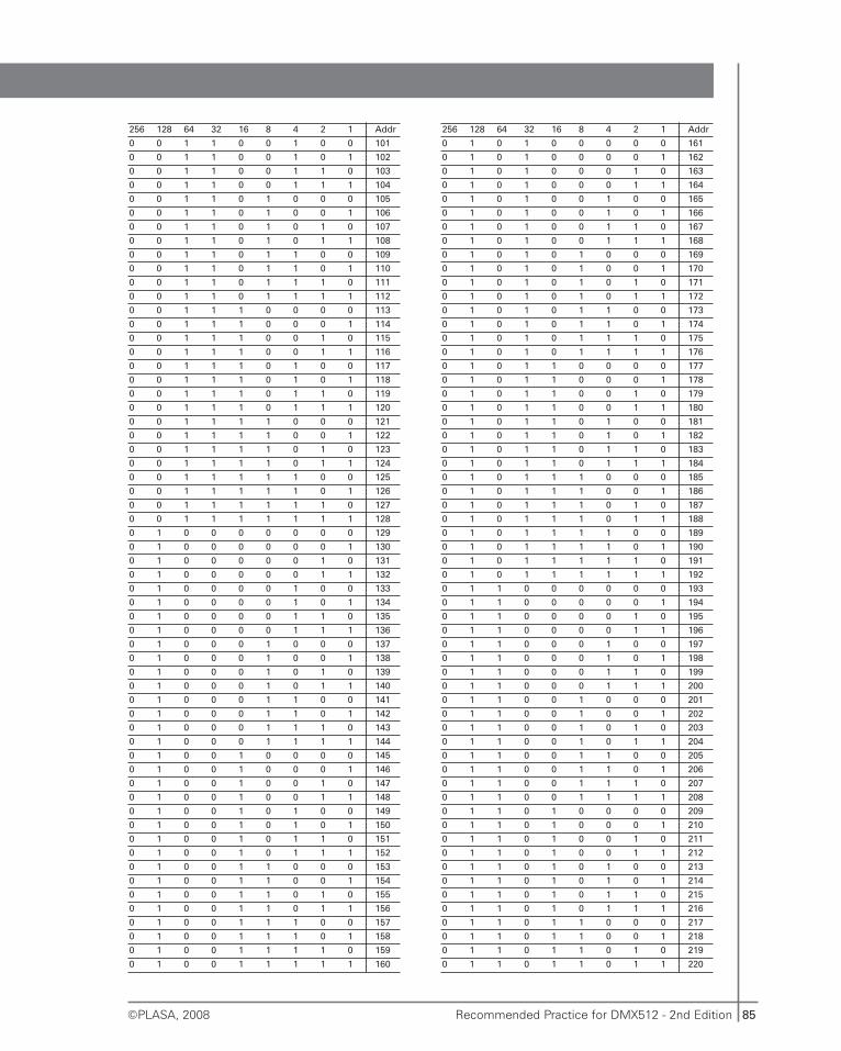
85Recommended Practice for DMX512 - 2nd Edition©PLASA, 2008
256 128 64 32 16 8 4 2 1 Addr
0 0 1 1 0 0 1 0 0 101
0 0 1 1 0 0 1 0 1 102
0 0 1 1 0 0 1 1 0 103
0 0 1 1 0 0 1 1 1 104
0 0 1 1 0 1 0 0 0 105
0 0 1 1 0 1 0 0 1 106
0 0 1 1 0 1 0 1 0 107
0 0 1 1 0 1 0 1 1 108
0 0 1 1 0 1 1 0 0 109
0 0 1 1 0 1 1 0 1 110
0 0 1 1 0 1 1 1 0 111
0 0 1 1 0 1 1 1 1 112
0 0 1 1 1 0 0 0 0 113
0 0 1 1 1 0 0 0 1 114
0 0 1 1 1 0 0 1 0 115
0 0 1 1 1 0 0 1 1 116
0 0 1 1 1 0 1 0 0 117
0 0 1 1 1 0 1 0 1 118
0 0 1 1 1 0 1 1 0 119
0 0 1 1 1 0 1 1 1 120
0 0 1 1 1 1 0 0 0 121
0 0 1 1 1 1 0 0 1 122
0 0 1 1 1 1 0 1 0 123
0 0 1 1 1 1 0 1 1 124
0 0 1 1 1 1 1 0 0 125
0 0 1 1 1 1 1 0 1 126
0 0 1 1 1 1 1 1 0 127
0 0 1 1 1 1 1 1 1 128
0 1 0 0 0 0 0 0 0 129
0 1 0 0 0 0 0 0 1 130
0 1 0 0 0 0 0 1 0 131
0 1 0 0 0 0 0 1 1 132
0 1 0 0 0 0 1 0 0 133
0 1 0 0 0 0 1 0 1 134
0 1 0 0 0 0 1 1 0 135
0 1 0 0 0 0 1 1 1 136
0 1 0 0 0 1 0 0 0 137
0 1 0 0 0 1 0 0 1 138
0 1 0 0 0 1 0 1 0 139
0 1 0 0 0 1 0 1 1 140
0 1 0 0 0 1 1 0 0 141
0 1 0 0 0 1 1 0 1 142
0 1 0 0 0 1 1 1 0 143
0 1 0 0 0 1 1 1 1 144
0 1 0 0 1 0 0 0 0 145
0 1 0 0 1 0 0 0 1 146
0 1 0 0 1 0 0 1 0 147
0 1 0 0 1 0 0 1 1 148
0 1 0 0 1 0 1 0 0 149
0 1 0 0 1 0 1 0 1 150
0 1 0 0 1 0 1 1 0 151
0 1 0 0 1 0 1 1 1 152
0 1 0 0 1 1 0 0 0 153
0 1 0 0 1 1 0 0 1 154
0 1 0 0 1 1 0 1 0 155
0 1 0 0 1 1 0 1 1 156
0 1 0 0 1 1 1 0 0 157
0 1 0 0 1 1 1 0 1 158
0 1 0 0 1 1 1 1 0 159
0 1 0 0 1 1 1 1 1 160
256 128 64 32 16 8 4 2 1 Addr
0 1 0 1 0 0 0 0 0 161
0 1 0 1 0 0 0 0 1 162
0 1 0 1 0 0 0 1 0 163
0 1 0 1 0 0 0 1 1 164
0 1 0 1 0 0 1 0 0 165
0 1 0 1 0 0 1 0 1 166
0 1 0 1 0 0 1 1 0 167
0 1 0 1 0 0 1 1 1 168
0 1 0 1 0 1 0 0 0 169
0 1 0 1 0 1 0 0 1 170
0 1 0 1 0 1 0 1 0 171
0 1 0 1 0 1 0 1 1 172
0 1 0 1 0 1 1 0 0 173
0 1 0 1 0 1 1 0 1 174
0 1 0 1 0 1 1 1 0 175
0 1 0 1 0 1 1 1 1 176
0 1 0 1 1 0 0 0 0 177
0 1 0 1 1 0 0 0 1 178
0 1 0 1 1 0 0 1 0 179
0 1 0 1 1 0 0 1 1 180
0 1 0 1 1 0 1 0 0 181
0 1 0 1 1 0 1 0 1 182
0 1 0 1 1 0 1 1 0 183
0 1 0 1 1 0 1 1 1 184
0 1 0 1 1 1 0 0 0 185
0 1 0 1 1 1 0 0 1 186
0 1 0 1 1 1 0 1 0 187
0 1 0 1 1 1 0 1 1 188
0 1 0 1 1 1 1 0 0 189
0 1 0 1 1 1 1 0 1 190
0 1 0 1 1 1 1 1 0 191
0 1 0 1 1 1 1 1 1 192
0 1 1 0 0 0 0 0 0 193
0 1 1 0 0 0 0 0 1 194
0 1 1 0 0 0 0 1 0 195
0 1 1 0 0 0 0 1 1 196
0 1 1 0 0 0 1 0 0 197
0 1 1 0 0 0 1 0 1 198
0 1 1 0 0 0 1 1 0 199
0 1 1 0 0 0 1 1 1 200
0 1 1 0 0 1 0 0 0 201
0 1 1 0 0 1 0 0 1 202
0 1 1 0 0 1 0 1 0 203
0 1 1 0 0 1 0 1 1 204
0 1 1 0 0 1 1 0 0 205
0 1 1 0 0 1 1 0 1 206
0 1 1 0 0 1 1 1 0 207
0 1 1 0 0 1 1 1 1 208
0 1 1 0 1 0 0 0 0 209
0 1 1 0 1 0 0 0 1 210
0 1 1 0 1 0 0 1 0 211
0 1 1 0 1 0 0 1 1 212
0 1 1 0 1 0 1 0 0 213
0 1 1 0 1 0 1 0 1 214
0 1 1 0 1 0 1 1 0 215
0 1 1 0 1 0 1 1 1 216
0 1 1 0 1 1 0 0 0 217
0 1 1 0 1 1 0 0 1 218
0 1 1 0 1 1 0 1 0 219
0 1 1 0 1 1 0 1 1 220
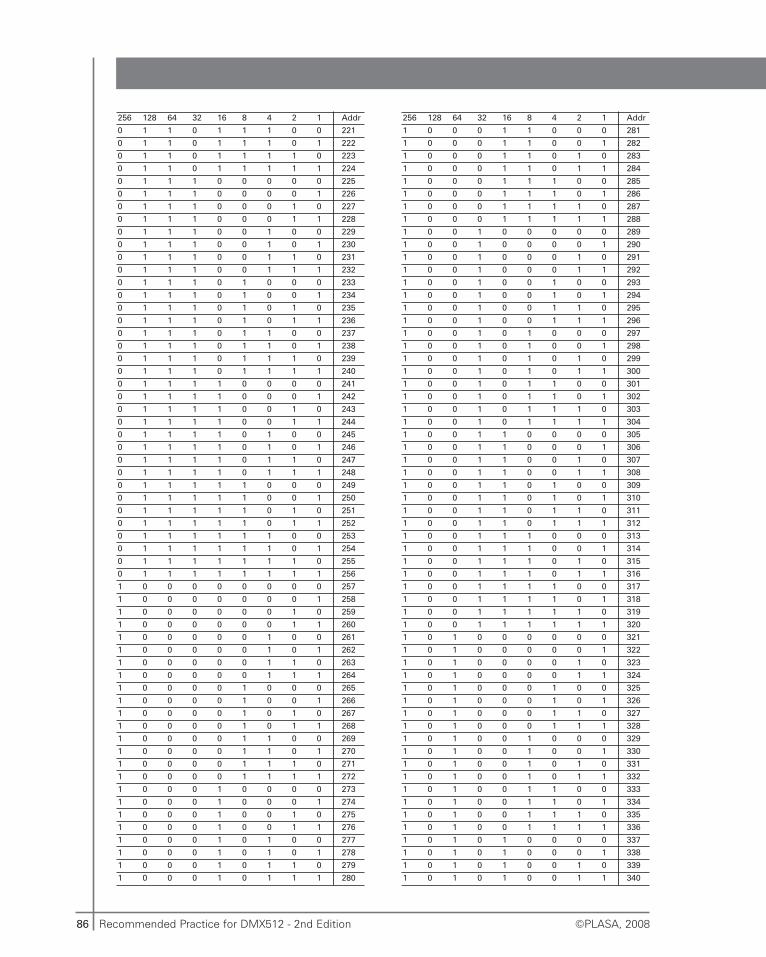
86 Recommended Practice for DMX512 - 2nd Edition ©PLASA, 2008
256 128 64 32 16 8 4 2 1 Addr
0 1 1 0 1 1 1 0 0 221
0 1 1 0 1 1 1 0 1 222
0 1 1 0 1 1 1 1 0 223
0 1 1 0 1 1 1 1 1 224
0 1 1 1 0 0 0 0 0 225
0 1 1 1 0 0 0 0 1 226
0 1 1 1 0 0 0 1 0 227
0 1 1 1 0 0 0 1 1 228
0 1 1 1 0 0 1 0 0 229
0 1 1 1 0 0 1 0 1 230
0 1 1 1 0 0 1 1 0 231
0 1 1 1 0 0 1 1 1 232
0 1 1 1 0 1 0 0 0 233
0 1 1 1 0 1 0 0 1 234
0 1 1 1 0 1 0 1 0 235
0 1 1 1 0 1 0 1 1 236
0 1 1 1 0 1 1 0 0 237
0 1 1 1 0 1 1 0 1 238
0 1 1 1 0 1 1 1 0 239
0 1 1 1 0 1 1 1 1 240
0 1 1 1 1 0 0 0 0 241
0 1 1 1 1 0 0 0 1 242
0 1 1 1 1 0 0 1 0 243
0 1 1 1 1 0 0 1 1 244
0 1 1 1 1 0 1 0 0 245
0 1 1 1 1 0 1 0 1 246
0 1 1 1 1 0 1 1 0 247
0 1 1 1 1 0 1 1 1 248
0 1 1 1 1 1 0 0 0 249
0 1 1 1 1 1 0 0 1 250
0 1 1 1 1 1 0 1 0 251
0 1 1 1 1 1 0 1 1 252
0 1 1 1 1 1 1 0 0 253
0 1 1 1 1 1 1 0 1 254
0 1 1 1 1 1 1 1 0 255
0 1 1 1 1 1 1 1 1 256
1 0 0 0 0 0 0 0 0 257
1 0 0 0 0 0 0 0 1 258
1 0 0 0 0 0 0 1 0 259
1 0 0 0 0 0 0 1 1 260
1 0 0 0 0 0 1 0 0 261
1 0 0 0 0 0 1 0 1 262
1 0 0 0 0 0 1 1 0 263
1 0 0 0 0 0 1 1 1 264
1 0 0 0 0 1 0 0 0 265
1 0 0 0 0 1 0 0 1 266
1 0 0 0 0 1 0 1 0 267
1 0 0 0 0 1 0 1 1 268
1 0 0 0 0 1 1 0 0 269
1 0 0 0 0 1 1 0 1 270
1 0 0 0 0 1 1 1 0 271
1 0 0 0 0 1 1 1 1 272
1 0 0 0 1 0 0 0 0 273
1 0 0 0 1 0 0 0 1 274
1 0 0 0 1 0 0 1 0 275
1 0 0 0 1 0 0 1 1 276
1 0 0 0 1 0 1 0 0 277
1 0 0 0 1 0 1 0 1 278
1 0 0 0 1 0 1 1 0 279
1 0 0 0 1 0 1 1 1 280
256 128 64 32 16 8 4 2 1 Addr
1 0 0 0 1 1 0 0 0 281
1 0 0 0 1 1 0 0 1 282
1 0 0 0 1 1 0 1 0 283
1 0 0 0 1 1 0 1 1 284
1 0 0 0 1 1 1 0 0 285
1 0 0 0 1 1 1 0 1 286
1 0 0 0 1 1 1 1 0 287
1 0 0 0 1 1 1 1 1 288
1 0 0 1 0 0 0 0 0 289
1 0 0 1 0 0 0 0 1 290
1 0 0 1 0 0 0 1 0 291
1 0 0 1 0 0 0 1 1 292
1 0 0 1 0 0 1 0 0 293
1 0 0 1 0 0 1 0 1 294
1 0 0 1 0 0 1 1 0 295
1 0 0 1 0 0 1 1 1 296
1 0 0 1 0 1 0 0 0 297
1 0 0 1 0 1 0 0 1 298
1 0 0 1 0 1 0 1 0 299
1 0 0 1 0 1 0 1 1 300
1 0 0 1 0 1 1 0 0 301
1 0 0 1 0 1 1 0 1 302
1 0 0 1 0 1 1 1 0 303
1 0 0 1 0 1 1 1 1 304
1 0 0 1 1 0 0 0 0 305
1 0 0 1 1 0 0 0 1 306
1 0 0 1 1 0 0 1 0 307
1 0 0 1 1 0 0 1 1 308
1 0 0 1 1 0 1 0 0 309
1 0 0 1 1 0 1 0 1 310
1 0 0 1 1 0 1 1 0 311
1 0 0 1 1 0 1 1 1 312
1 0 0 1 1 1 0 0 0 313
1 0 0 1 1 1 0 0 1 314
1 0 0 1 1 1 0 1 0 315
1 0 0 1 1 1 0 1 1 316
1 0 0 1 1 1 1 0 0 317
1 0 0 1 1 1 1 0 1 318
1 0 0 1 1 1 1 1 0 319
1 0 0 1 1 1 1 1 1 320
1 0 1 0 0 0 0 0 0 321
1 0 1 0 0 0 0 0 1 322
1 0 1 0 0 0 0 1 0 323
1 0 1 0 0 0 0 1 1 324
1 0 1 0 0 0 1 0 0 325
1 0 1 0 0 0 1 0 1 326
1 0 1 0 0 0 1 1 0 327
1 0 1 0 0 0 1 1 1 328
1 0 1 0 0 1 0 0 0 329
1 0 1 0 0 1 0 0 1 330
1 0 1 0 0 1 0 1 0 331
1 0 1 0 0 1 0 1 1 332
1 0 1 0 0 1 1 0 0 333
1 0 1 0 0 1 1 0 1 334
1 0 1 0 0 1 1 1 0 335
1 0 1 0 0 1 1 1 1 336
1 0 1 0 1 0 0 0 0 337
1 0 1 0 1 0 0 0 1 338
1 0 1 0 1 0 0 1 0 339
1 0 1 0 1 0 0 1 1 340
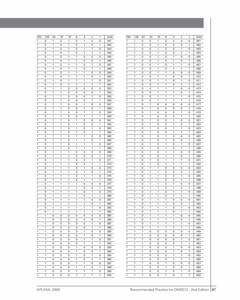
87Recommended Practice for DMX512 - 2nd Edition©PLASA, 2008
256 128 64 32 16 8 4 2 1 Addr
1 0 1 0 1 0 1 0 0 341
1 0 1 0 1 0 1 0 1 342
1 0 1 0 1 0 1 1 0 343
1 0 1 0 1 0 1 1 1 344
1 0 1 0 1 1 0 0 0 345
1 0 1 0 1 1 0 0 1 346
1 0 1 0 1 1 0 1 0 347
1 0 1 0 1 1 0 1 1 348
1 0 1 0 1 1 1 0 0 349
1 0 1 0 1 1 1 0 1 350
1 0 1 0 1 1 1 1 0 351
1 0 1 0 1 1 1 1 1 352
1 0 1 1 0 0 0 0 0 353
1 0 1 1 0 0 0 0 1 354
1 0 1 1 0 0 0 1 0 355
1 0 1 1 0 0 0 1 1 356
1 0 1 1 0 0 1 0 0 357
1 0 1 1 0 0 1 0 1 358
1 0 1 1 0 0 1 1 0 359
1 0 1 1 0 0 1 1 1 360
1 0 1 1 0 1 0 0 0 361
1 0 1 1 0 1 0 0 1 362
1 0 1 1 0 1 0 1 0 363
1 0 1 1 0 1 0 1 1 364
1 0 1 1 0 1 1 0 0 365
1 0 1 1 0 1 1 0 1 366
1 0 1 1 0 1 1 1 0 367
1 0 1 1 0 1 1 1 1 368
1 0 1 1 1 0 0 0 0 369
1 0 1 1 1 0 0 0 1 370
1 0 1 1 1 0 0 1 0 371
1 0 1 1 1 0 0 1 1 372
1 0 1 1 1 0 1 0 0 373
1 0 1 1 1 0 1 0 1 374
1 0 1 1 1 0 1 1 0 375
1 0 1 1 1 0 1 1 1 376
1 0 1 1 1 1 0 0 0 377
1 0 1 1 1 1 0 0 1 378
1 0 1 1 1 1 0 1 0 379
1 0 1 1 1 1 0 1 1 380
1 0 1 1 1 1 1 0 0 381
1 0 1 1 1 1 1 0 1 382
1 0 1 1 1 1 1 1 0 383
1 0 1 1 1 1 1 1 1 384
1 1 0 0 0 0 0 0 0 385
1 1 0 0 0 0 0 0 1 386
1 1 0 0 0 0 0 1 0 387
1 1 0 0 0 0 0 1 1 388
1 1 0 0 0 0 1 0 0 389
1 1 0 0 0 0 1 0 1 390
1 1 0 0 0 0 1 1 0 391
1 1 0 0 0 0 1 1 1 392
1 1 0 0 0 1 0 0 0 393
1 1 0 0 0 1 0 0 1 394
1 1 0 0 0 1 0 1 0 395
1 1 0 0 0 1 0 1 1 396
1 1 0 0 0 1 1 0 0 397
1 1 0 0 0 1 1 0 1 398
1 1 0 0 0 1 1 1 0 399
1 1 0 0 0 1 1 1 1 400
256 128 64 32 16 8 4 2 1 Addr
1 1 0 0 1 0 0 0 0 401
1 1 0 0 1 0 0 0 1 402
1 1 0 0 1 0 0 1 0 403
1 1 0 0 1 0 0 1 1 404
1 1 0 0 1 0 1 0 0 405
1 1 0 0 1 0 1 0 1 406
1 1 0 0 1 0 1 1 0 407
1 1 0 0 1 0 1 1 1 408
1 1 0 0 1 1 0 0 0 409
1 1 0 0 1 1 0 0 1 410
1 1 0 0 1 1 0 1 0 411
1 1 0 0 1 1 0 1 1 412
1 1 0 0 1 1 1 0 0 413
1 1 0 0 1 1 1 0 1 414
1 1 0 0 1 1 1 1 0 415
1 1 0 0 1 1 1 1 1 416
1 1 0 1 0 0 0 0 0 417
1 1 0 1 0 0 0 0 1 418
1 1 0 1 0 0 0 1 0 419
1 1 0 1 0 0 0 1 1 420
1 1 0 1 0 0 1 0 0 421
1 1 0 1 0 0 1 0 1 422
1 1 0 1 0 0 1 1 0 423
1 1 0 1 0 0 1 1 1 424
1 1 0 1 0 1 0 0 0 425
1 1 0 1 0 1 0 0 1 426
1 1 0 1 0 1 0 1 0 427
1 1 0 1 0 1 0 1 1 428
1 1 0 1 0 1 1 0 0 429
1 1 0 1 0 1 1 0 1 430
1 1 0 1 0 1 1 1 0 431
1 1 0 1 0 1 1 1 1 432
1 1 0 1 1 0 0 0 0 433
1 1 0 1 1 0 0 0 1 434
1 1 0 1 1 0 0 1 0 435
1 1 0 1 1 0 0 1 1 436
1 1 0 1 1 0 1 0 0 437
1 1 0 1 1 0 1 0 1 438
1 1 0 1 1 0 1 1 0 439
1 1 0 1 1 0 1 1 1 440
1 1 0 1 1 1 0 0 0 441
1 1 0 1 1 1 0 0 1 442
1 1 0 1 1 1 0 1 0 443
1 1 0 1 1 1 0 1 1 444
1 1 0 1 1 1 1 0 0 445
1 1 0 1 1 1 1 0 1 446
1 1 0 1 1 1 1 1 0 447
1 1 0 1 1 1 1 1 1 448
1 1 1 0 0 0 0 0 0 449
1 1 1 0 0 0 0 0 1 450
1 1 1 0 0 0 0 1 0 451
1 1 1 0 0 0 0 1 1 452
1 1 1 0 0 0 1 0 0 453
1 1 1 0 0 0 1 0 1 454
1 1 1 0 0 0 1 1 0 455
1 1 1 0 0 0 1 1 1 456
1 1 1 0 0 1 0 0 0 457
1 1 1 0 0 1 0 0 1 458
1 1 1 0 0 1 0 1 0 459
1 1 1 0 0 1 0 1 1 460
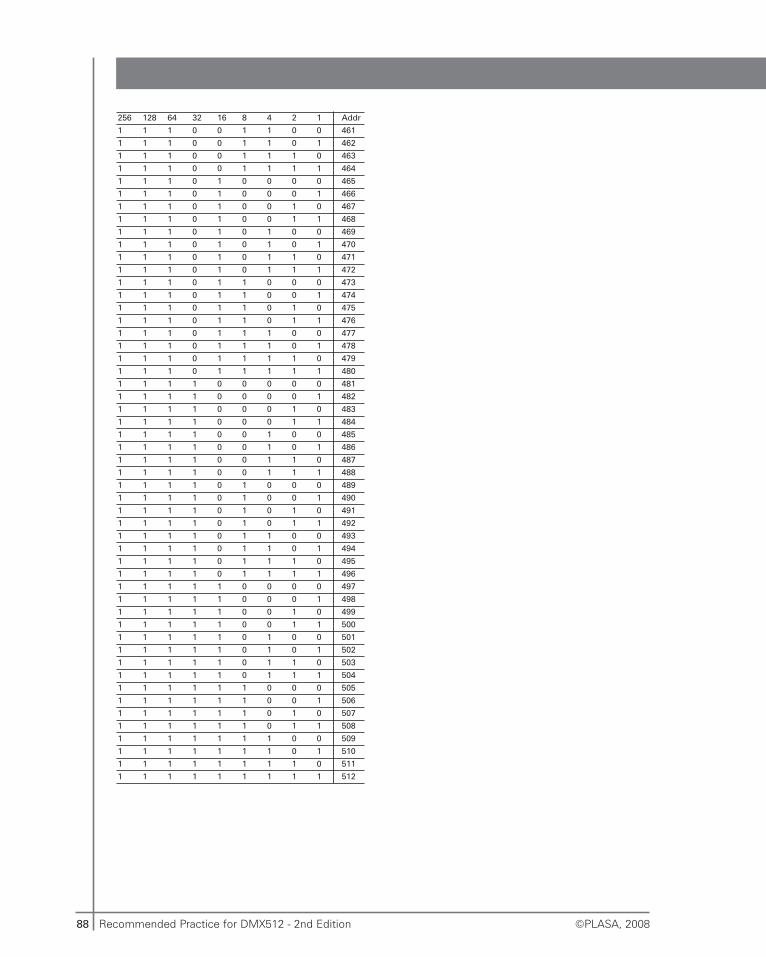
88 Recommended Practice for DMX512 - 2nd Edition ©PLASA, 2008
256 128 64 32 16 8 4 2 1 Addr
1 1 1 0 0 1 1 0 0 461
1 1 1 0 0 1 1 0 1 462
1 1 1 0 0 1 1 1 0 463
1 1 1 0 0 1 1 1 1 464
1 1 1 0 1 0 0 0 0 465
1 1 1 0 1 0 0 0 1 466
1 1 1 0 1 0 0 1 0 467
1 1 1 0 1 0 0 1 1 468
1 1 1 0 1 0 1 0 0 469
1 1 1 0 1 0 1 0 1 470
1 1 1 0 1 0 1 1 0 471
1 1 1 0 1 0 1 1 1 472
1 1 1 0 1 1 0 0 0 473
1 1 1 0 1 1 0 0 1 474
1 1 1 0 1 1 0 1 0 475
1 1 1 0 1 1 0 1 1 476
1 1 1 0 1 1 1 0 0 477
1 1 1 0 1 1 1 0 1 478
1 1 1 0 1 1 1 1 0 479
1 1 1 0 1 1 1 1 1 480
1 1 1 1 0 0 0 0 0 481
1 1 1 1 0 0 0 0 1 482
1 1 1 1 0 0 0 1 0 483
1 1 1 1 0 0 0 1 1 484
1 1 1 1 0 0 1 0 0 485
1 1 1 1 0 0 1 0 1 486
1 1 1 1 0 0 1 1 0 487
1 1 1 1 0 0 1 1 1 488
1 1 1 1 0 1 0 0 0 489
1 1 1 1 0 1 0 0 1 490
1 1 1 1 0 1 0 1 0 491
1 1 1 1 0 1 0 1 1 492
1 1 1 1 0 1 1 0 0 493
1 1 1 1 0 1 1 0 1 494
1 1 1 1 0 1 1 1 0 495
1 1 1 1 0 1 1 1 1 496
1 1 1 1 1 0 0 0 0 497
1 1 1 1 1 0 0 0 1 498
1 1 1 1 1 0 0 1 0 499
1 1 1 1 1 0 0 1 1 500
1 1 1 1 1 0 1 0 0 501
1 1 1 1 1 0 1 0 1 502
1 1 1 1 1 0 1 1 0 503
1 1 1 1 1 0 1 1 1 504
1 1 1 1 1 1 0 0 0 505
1 1 1 1 1 1 0 0 1 506
1 1 1 1 1 1 0 1 0 507
1 1 1 1 1 1 0 1 1 508
1 1 1 1 1 1 1 0 0 509
1 1 1 1 1 1 1 0 1 510
1 1 1 1 1 1 1 1 0 511
1 1 1 1 1 1 1 1 1 512
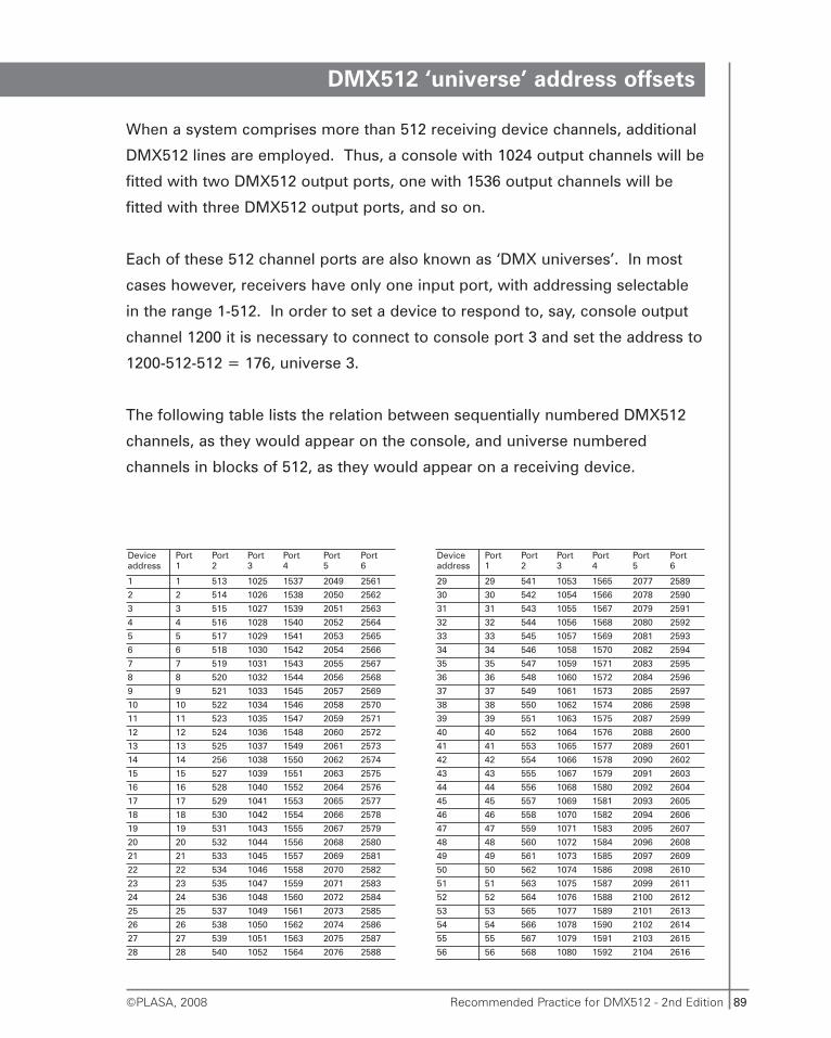
89Recommended Practice for DMX512 - 2nd Edition©PLASA, 2008
DMX512 ‘universe’ address offsets
When a system comprises more than 512 receiving device channels, additional
DMX512 lines are employed. Thus, a console with 1024 output channels will be
fitted with two DMX512 output ports, one with 1536 output channels will be
fitted with three DMX512 output ports, and so on.
Each of these 512 channel ports are also known as ‘DMX universes’. In most
cases however, receivers have only one input port, with addressing selectable
in the range 1-512. In order to set a device to respond to, say, console output
channel 1200 it is necessary to connect to console port 3 and set the address to
1200-512-512 = 176, universe 3.
The following table lists the relation between sequentially numbered DMX512
channels, as they would appear on the console, and universe numbered
channels in blocks of 512, as they would appear on a receiving device.
Deviceaddress
Port 1
Port 2
Port 3
Port 4
Port 5
Port 6
1 1 513 1025 1537 2049 2561
2 2 514 1026 1538 2050 2562
3 3 515 1027 1539 2051 2563
4 4 516 1028 1540 2052 2564
5 5 517 1029 1541 2053 2565
6 6 518 1030 1542 2054 2566
7 7 519 1031 1543 2055 2567
8 8 520 1032 1544 2056 2568
9 9 521 1033 1545 2057 2569
10 10 522 1034 1546 2058 2570
11 11 523 1035 1547 2059 2571
12 12 524 1036 1548 2060 2572
13 13 525 1037 1549 2061 2573
14 14 256 1038 1550 2062 2574
15 15 527 1039 1551 2063 2575
16 16 528 1040 1552 2064 2576
17 17 529 1041 1553 2065 2577
18 18 530 1042 1554 2066 2578
19 19 531 1043 1555 2067 2579
20 20 532 1044 1556 2068 2580
21 21 533 1045 1557 2069 2581
22 22 534 1046 1558 2070 2582
23 23 535 1047 1559 2071 2583
24 24 536 1048 1560 2072 2584
25 25 537 1049 1561 2073 2585
26 26 538 1050 1562 2074 2586
27 27 539 1051 1563 2075 2587
28 28 540 1052 1564 2076 2588
Deviceaddress
Port 1
Port 2
Port 3
Port 4
Port 5
Port 6
29 29 541 1053 1565 2077 2589
30 30 542 1054 1566 2078 2590
31 31 543 1055 1567 2079 2591
32 32 544 1056 1568 2080 2592
33 33 545 1057 1569 2081 2593
34 34 546 1058 1570 2082 2594
35 35 547 1059 1571 2083 2595
36 36 548 1060 1572 2084 2596
37 37 549 1061 1573 2085 2597
38 38 550 1062 1574 2086 2598
39 39 551 1063 1575 2087 2599
40 40 552 1064 1576 2088 2600
41 41 553 1065 1577 2089 2601
42 42 554 1066 1578 2090 2602
43 43 555 1067 1579 2091 2603
44 44 556 1068 1580 2092 2604
45 45 557 1069 1581 2093 2605
46 46 558 1070 1582 2094 2606
47 47 559 1071 1583 2095 2607
48 48 560 1072 1584 2096 2608
49 49 561 1073 1585 2097 2609
50 50 562 1074 1586 2098 2610
51 51 563 1075 1587 2099 2611
52 52 564 1076 1588 2100 2612
53 53 565 1077 1589 2101 2613
54 54 566 1078 1590 2102 2614
55 55 567 1079 1591 2103 2615
56 56 568 1080 1592 2104 2616
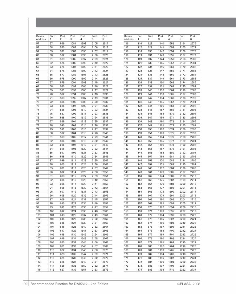
90 Recommended Practice for DMX512 - 2nd Edition ©PLASA, 2008
Deviceaddress
Port 1
Port 2
Port 3
Port 4
Port5
Port 6
57 57 569 1081 1593 2105 2617
58 58 570 1082 1594 2106 2618
59 59 571 1083 1595 2107 2619
60 60 572 1084 1596 2108 2620
61 61 573 1085 1597 2109 2621
62 62 574 1086 1598 2110 2622
63 63 575 1087 1599 2111 2623
64 64 576 1088 1600 2112 2624
65 65 577 1089 1601 2113 2625
66 66 578 1090 1602 2114 2626
67 67 579 1091 1603 2115 2627
68 68 580 1092 1604 2116 2628
69 69 581 1093 1605 2117 2629
70 70 582 1094 1606 2118 2630
71 71 583 1095 1607 2119 2631
72 72 584 1096 1608 2120 2632
73 73 585 1097 1609 2121 2633
74 74 586 1098 1610 2122 2634
75 75 587 1099 1611 2123 2635
76 76 588 1100 1612 2124 2636
77 77 589 1101 1613 2125 2637
78 78 590 1102 1614 2126 2638
79 79 591 1103 1615 2127 2639
80 80 592 1104 1616 2128 2640
81 81 593 1105 1617 2129 2641
82 82 594 1106 1618 2130 2642
83 83 595 1107 1619 2131 2643
84 84 596 1108 1620 2132 2644
85 85 597 1109 1621 2133 2645
86 86 598 1110 1622 2134 2646
87 87 599 1111 1623 2135 2647
88 88 600 1112 1624 2136 2648
89 89 601 1113 1625 2137 2649
90 90 602 1114 1626 2138 2650
91 91 603 1115 1627 2139 2651
92 92 604 1116 1628 3140 2652
93 93 605 1117 1629 2141 2653
94 94 606 1118 1630 2142 2654
95 95 607 1119 1631 2143 2655
96 96 608 1120 1632 2144 2656
97 97 609 1121 1633 2145 2657
98 98 610 1122 1634 2146 2658
99 99 611 1123 1635 2147 2659
100 100 612 1124 1636 2148 2660
101 101 613 1125 1637 2149 2661
102 102 614 1126 1638 2150 2662
103 103 615 1127 1639 2151 2663
104 104 616 1128 1640 2152 2664
105 105 617 1129 1641 2153 2665
106 106 618 1130 1642 2154 2666
107 107 619 1131 1643 2155 2667
108 108 620 1132 1644 2156 2668
109 109 621 1133 1645 2157 2669
110 110 622 1134 1646 2158 2670
111 111 623 1135 1647 2159 2671
112 112 624 1136 1648 2160 2672
113 113 625 1137 1649 2161 2673
114 114 626 1138 1650 2162 2674
115 115 627 1139 1651 2163 2675
Deviceaddress
Port 1
Port 2
Port 3
Port 4
Port5
Port 6
116 116 628 1140 1652 2164 2676
117 117 629 1141 1653 2165 2677
118 118 630 1142 1654 2166 2678
119 119 631 1143 1655 2167 2679
120 120 632 1144 1656 2168 2680
121 121 633 1145 1657 2169 2681
122 122 634 1146 1658 2170 2682
123 123 635 1147 1659 2171 2683
124 124 636 1148 1660 2172 2684
125 125 637 1149 1661 2173 2685
126 126 638 1150 1662 2174 2686
127 127 639 1151 1663 2175 2687
128 128 640 1152 1664 2176 2688
129 129 641 1153 1665 2177 2689
130 130 642 1154 1666 2178 2690
131 131 643 1155 1667 2179 2691
132 132 644 1156 1668 2180 2692
133 133 645 1157 1669 2181 2693
134 134 646 1158 1670 2182 2694
135 135 647 1159 1671 2183 2695
136 136 648 1160 1672 2184 2696
137 137 649 1161 1673 2185 2697
138 138 650 1162 1674 2186 2698
139 139 651 1163 1675 2187 2699
140 140 652 1164 1676 2188 2700
141 141 653 1165 1677 2189 2701
142 142 654 1166 1678 2190 2702
143 143 655 1167 1679 2191 2703
144 144 656 1168 1680 2192 2704
145 145 657 1169 1681 2193 2705
146 146 658 1170 1682 2194 2706
147 147 659 1171 1683 2195 2707
148 148 660 1172 1684 2196 2708
149 149 661 1173 1685 2197 2709
150 150 662 1174 1686 2198 2710
151 151 663 1175 1687 2199 2711
152 152 664 1176 1688 2200 2712
153 153 665 1177 1689 2201 2713
154 154 666 1178 1690 2202 2714
155 155 667 1179 1691 2203 2715
156 156 668 1180 1692 2204 2716
157 157 669 1181 1693 2205 2717
158 158 670 1182 1694 2206 2718
159 159 671 1183 1695 2207 2719
160 160 672 1184 1696 2208 2720
161 161 673 1185 1697 2209 2721
162 162 674 1186 1698 2210 2722
163 163 675 1187 1699 2211 2723
164 164 676 1188 1700 2212 2724
165 165 677 1189 1701 2213 2725
166 166 678 1190 1702 2214 2726
167 167 679 1191 1703 2215 2727
168 168 680 1192 1704 2216 2728
169 169 681 1193 1705 2217 2729
170 170 682 1194 1706 2218 2730
171 171 683 1195 1707 2219 2731
172 172 684 1196 1708 2220 2732
173 173 685 1197 1709 2221 2733
174 174 686 1198 1710 2222 2734
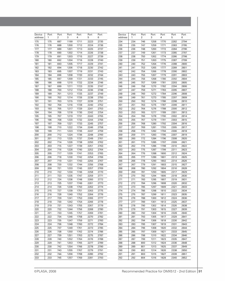
91Recommended Practice for DMX512 - 2nd Edition©PLASA, 2008
Deviceaddress
Port1
Port 2
Port3
Port4
Port5
Port6
175 175 687 1199 1711 2223 2735
176 176 688 1200 1712 2224 2736
177 177 689 1201 1713 2225 2737
178 178 690 1202 1714 2226 2738
179 179 691 1203 1715 2227 2739
180 180 692 1204 1716 2228 2740
181 181 693 1205 1717 2229 2741
182 182 694 1206 1718 2230 2742
183 183 695 1207 1719 2231 2743
184 184 696 1208 1720 2232 2744
185 185 697 1209 1721 2233 2745
186 186 698 1210 1722 2234 2746
187 187 699 1211 1723 2235 2747
188 188 700 1212 1724 2236 2748
189 189 701 1213 1725 2237 2749
190 190 702 1214 1726 2238 2750
191 191 703 1215 1727 2239 2751
192 192 704 1216 1728 2240 2752
193 193 705 1217 1729 2241 2753
194 194 706 1218 1730 2242 2754
195 195 707 1219 1731 2243 2755
196 196 708 1220 1732 2244 2756
197 197 709 1221 1733 2245 2757
198 198 710 1222 1734 2246 2758
199 199 711 1223 1735 2247 2759
200 200 712 1224 1736 2248 2760
201 201 713 1225 1737 2249 2761
202 202 714 1226 1738 2250 2762
203 203 715 1227 1739 2251 2763
204 204 716 1228 1740 2252 2764
205 205 717 1229 1741 2253 2765
206 206 718 1230 1742 2254 2766
207 207 719 1231 1743 2255 2767
208 208 720 1232 1744 2256 2768
209 209 721 1233 1745 2257 2769
210 210 722 1234 1746 2258 2770
211 211 723 1235 1747 2259 2771
212 212 724 1236 1748 2260 2772
213 213 725 1237 1749 2261 2773
214 214 726 1238 1750 2262 2774
215 215 727 1239 1751 2263 2775
216 216 728 1240 1752 2264 2776
217 217 729 1241 1753 2265 2777
218 218 730 1242 1754 2266 2778
219 219 731 1243 1755 2267 2779
220 220 732 1244 1756 2268 2780
221 221 733 1245 1757 2269 2781
222 222 734 1246 1758 2270 2782
223 223 735 1247 1759 2271 2783
224 224 736 1248 1760 2272 2784
225 225 737 1249 1761 2273 2785
226 226 738 1250 1762 2274 2786
227 227 739 1251 1763 2275 2787
228 228 740 1252 1764 2276 2788
229 229 741 1253 1765 2277 2789
230 230 742 1254 1766 2278 2790
231 231 743 1255 1767 2279 2791
232 232 744 1256 1768 2280 2792
233 233 745 1257 1769 2281 2793
Deviceaddress
Port1
Port2
Port 3
Port 4
Port5
Port 6
234 234 746 1258 1770 2282 2794
235 235 747 1259 1771 2283 2795
236 236 748 1260 1772 2284 2796
237 237 749 1261 1773 2285 2797
238 238 750 1262 1774 2286 2798
239 239 751 1263 1775 2287 2799
240 240 752 1264 1776 2288 2800
241 241 753 1265 1777 2289 2801
242 242 754 1266 1778 2290 2802
243 243 755 1267 1779 2291 2803
244 244 756 1268 1780 2292 2804
245 245 757 1269 1781 2293 2805
246 246 758 1270 1782 2294 2806
247 247 759 1271 1783 2295 2807
248 248 760 1272 1784 2296 2808
249 249 761 1273 1785 2297 2809
250 250 762 1274 1786 2298 2810
251 251 763 1275 1787 2299 2811
252 252 764 1276 1788 2300 2812
253 253 765 1277 1789 2301 2813
254 254 766 1278 1790 2302 2814
255 255 767 1279 1791 2303 2815
256 256 768 1280 1792 2304 2816
257 257 769 1281 1793 2305 2817
258 258 770 1282 1794 2306 2818
259 259 771 1283 1795 2307 2819
260 260 772 1284 1796 2308 2820
261 261 773 1285 1797 2309 2821
262 262 774 1286 1798 2310 2822
263 263 775 1287 1799 2311 2823
264 264 776 1288 1800 2312 2824
265 265 777 1289 1801 2313 2825
266 266 778 1290 1802 2314 2826
267 267 779 1291 1803 2315 2827
268 268 780 1292 1804 2316 2828
269 269 781 1293 1805 2317 2829
270 270 782 1294 1806 2318 2830
271 271 783 1295 1807 2319 2831
272 272 784 1296 1808 2320 2832
273 273 785 1297 1809 2321 2833
274 274 786 1298 1810 2322 2834
275 275 787 1299 1811 2323 2835
276 276 788 1300 1812 2324 2836
277 277 789 1301 1813 2325 2837
278 278 790 1302 1814 2326 2838
279 279 791 1303 1815 2327 2839
280 280 792 1304 1816 2328 2840
281 281 793 1305 1817 2329 2841
282 282 794 1306 1818 2330 2842
283 283 795 1307 1819 2331 2843
284 284 796 1308 1820 2332 2844
285 285 797 1309 1821 2333 2845
286 286 798 1310 1822 2334 2846
287 287 799 1311 1823 2335 2847
288 288 800 1312 1824 2336 2848
289 289 801 1313 1825 2337 2849
290 290 802 1314 1826 2338 2850
291 291 803 1315 1827 2339 2851
292 292 804 1316 1828 2340 2852
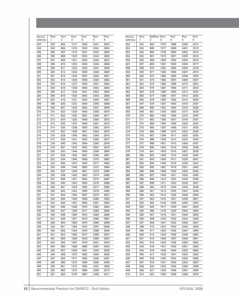
92 Recommended Practice for DMX512 - 2nd Edition ©PLASA, 2008
Deviceaddress
Port1
Port2
Port 3
Port 4
Port5
Port 6
293 293 805 1317 1829 2341 2853
294 294 806 1318 1830 2342 2854
295 295 807 1319 1831 2343 2855
296 296 808 1320 1832 2344 2856
297 297 809 1321 1833 2345 2857
298 298 810 1322 1834 2346 2858
299 299 811 1323 1835 2347 2859
300 300 812 1324 1836 2348 2860
301 301 813 1325 1837 2349 2861
302 302 814 1326 1838 2350 2862
303 303 815 1327 1839 2351 2863
304 304 816 1328 1840 2352 2864
305 305 817 1329 1841 2353 2865
306 306 818 1330 1842 2354 2866
307 307 819 1331 1843 2355 2867
308 308 820 1332 1844 2356 2868
309 309 821 1333 1845 2357 2869
310 310 822 1334 1846 2358 2870
311 311 823 1335 1847 2359 2871
312 312 824 1336 1848 2360 2872
313 313 825 1337 1849 2361 2873
314 314 826 1338 1850 2362 2874
315 315 827 1339 1851 2363 2875
316 316 828 1340 1852 2364 2876
317 317 829 1341 1853 2365 2877
318 318 830 1342 1854 2366 2878
319 319 831 1343 1855 2367 2879
320 320 832 1344 1856 2368 2880
321 321 833 1345 1857 2369 2881
322 322 834 1346 1858 2370 2882
323 323 835 1347 1859 2371 2883
324 324 836 1348 1860 2372 2884
325 325 837 1349 1861 2373 2885
326 326 838 1350 1862 2374 2886
327 327 839 1351 1863 2375 2887
328 328 840 1352 1864 2376 2888
329 329 841 1353 1865 2377 2889
330 330 842 1354 1866 2378 2890
331 331 843 1355 1867 2379 2891
332 332 844 1356 1868 2380 2892
333 333 845 1357 1869 2381 2893
334 334 846 1358 1870 2382 2894
335 335 847 1359 1871 2383 2895
336 336 848 1360 1872 2384 2896
337 337 849 1361 1873 2385 2897
338 338 850 1362 1874 2386 2898
339 339 851 1363 1875 2387 2899
340 340 852 1364 1876 2388 2900
341 341 853 1365 1877 2389 2901
342 342 854 1366 1878 2390 2902
343 343 855 1367 1879 2391 2903
344 344 856 1368 1880 2392 2904
345 345 857 1369 1881 2393 2905
346 346 858 1370 1882 2394 2906
347 347 859 1371 1883 2395 2907
348 348 860 1372 1884 2396 2908
349 349 861 1373 1885 2397 2909
350 350 862 1374 1886 2398 2910
351 351 863 1375 1887 2399 2911
Deviceaddress
Port1
924Port2
Port 3
Port 4
Port5
Port 6
352 352 864 1376 1888 2400 2912
353 353 685 1377 1889 2401 2913
354 354 866 1378 1890 2402 2914
355 355 867 1379 1891 2403 2915
356 356 868 1380 1892 2404 2916
357 357 869 1381 1893 2405 2917
358 358 870 1382 1894 2406 2918
359 359 871 1383 1895 2407 2919
360 360 872 1384 1896 2408 2920
361 361 873 1385 1897 2409 2921
362 362 874 1386 1898 2410 2922
363 363 875 1387 1899 2411 2923
364 364 876 1388 1900 2412 2924
365 365 877 1389 1901 2413 2925
366 366 878 1390 1902 2414 2926
367 367 879 1391 1903 2415 2927
368 368 880 1392 1904 2416 2928
369 369 881 1393 1905 2417 2929
370 370 882 1394 1906 2418 2930
371 371 883 1395 1907 2419 2931
372 372 884 1396 1908 2420 2932
373 373 885 1397 1909 2421 2933
374 374 886 1398 1910 2422 2934
375 375 887 1399 1911 2423 2935
376 376 888 1400 1912 2424 2936
377 377 889 1401 1913 2425 2937
378 378 890 1402 1914 2426 2938
379 379 891 1403 1915 2427 2939
380 380 892 1404 1916 2428 2940
381 381 893 1405 1917 2429 2941
382 382 894 1406 1918 2430 2942
383 383 895 1407 1919 2431 2943
384 384 896 1408 1920 2432 2944
385 385 897 1409 1921 2433 2945
386 386 898 1410 1922 2434 2946
387 387 899 1411 1923 2435 2947
388 388 900 1412 1924 2436 2948
389 389 901 1413 1925 2437 2949
390 390 902 1414 1926 2428 2950
391 391 903 1415 1927 2439 2951
392 392 904 1416 1928 2440 2952
393 393 905 1417 1929 2441 2953
394 394 906 1418 1930 2442 2954
395 395 907 1419 1931 2443 2955
396 396 908 1420 1932 2444 2956
397 397 909 1421 1933 2445 2957
398 398 910 1422 1934 2446 2958
399 399 911 1423 1935 2447 2959
400 400 912 1424 1936 2448 2960
401 401 913 1425 1937 2449 2961
402 402 914 1426 1938 2450 2962
403 403 915 1427 1939 2451 2963
404 404 916 1428 1940 2452 2964
405 405 917 1429 1941 2453 2965
406 406 918 1430 1942 2454 2966
407 407 919 1431 1943 2455 2967
408 408 920 1432 1944 2456 2968
409 409 921 1433 1945 2457 2969
410 410 922 1434 1946 2458 2970
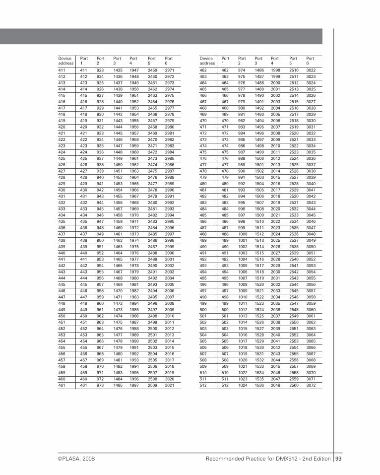
93Recommended Practice for DMX512 - 2nd Edition©PLASA, 2008
Deviceaddress
Port1
Port2
Port 3
Port 4
Port5
Port 6
411 411 923 1435 1947 2459 2971
412 412 924 1436 1948 2460 2972
413 413 925 1437 1949 2461 2973
414 414 926 1438 1950 2462 2974
415 415 927 1439 1951 2463 2975
416 416 928 1440 1952 2464 2976
417 417 929 1441 1953 2465 2977
418 418 930 1442 1954 2466 2978
419 419 931 1443 1955 2467 2979
420 420 932 1444 1956 2468 2980
421 421 933 1445 1957 2469 2981
422 422 934 1446 1958 2470 2982
423 423 935 1447 1959 2471 2983
424 424 936 1448 1960 2472 2984
425 425 937 1449 1961 2473 2985
426 426 938 1450 1962 2474 2986
427 427 939 1451 1963 2475 2987
428 428 940 1452 1964 2476 2988
429 429 941 1453 1965 2477 2989
430 430 942 1454 1966 2478 2990
431 431 943 1455 1967 2479 2991
432 432 944 1456 1968 2480 2992
433 433 945 1457 1969 2481 2993
434 434 946 1458 1970 2482 2994
435 435 947 1459 1971 2483 2995
436 436 948 1460 1972 2484 2996
437 437 949 1461 1973 2485 2997
438 438 950 1462 1974 2486 2998
439 439 951 1463 1975 2487 2999
440 440 952 1464 1976 2488 3000
441 441 953 1465 1977 2489 3001
442 442 954 1466 1978 2490 3002
443 443 955 1467 1979 2491 3003
444 444 956 1468 1980 2492 3004
445 445 957 1469 1981 2493 3005
446 446 958 1470 1982 2494 3006
447 447 959 1471 1983 2495 3007
448 448 960 1472 1984 2496 3008
449 449 961 1473 1985 2497 3009
450 450 962 1474 1986 2498 3010
451 451 963 1475 1987 2499 3011
452 452 964 1476 1988 2500 3012
453 453 965 1477 1989 2501 3013
454 454 966 1478 1990 2502 3014
455 455 967 1479 1991 2503 3015
456 456 968 1480 1992 2504 3016
457 457 969 1481 1993 2505 3017
458 458 970 1482 1994 2506 3018
459 459 971 1483 1995 2507 3019
460 460 972 1484 1996 2508 3020
461 461 973 1485 1997 2509 3021
Deviceaddress
Port1
Port2
Port 3
Port 4
Port5
Port 6
462 462 974 1486 1998 2510 3022
463 463 975 1487 1999 2511 3023
464 464 976 1488 2000 2512 3024
465 465 977 1489 2001 2513 3025
466 466 978 1490 2002 2514 3026
467 467 979 1491 2003 2515 3027
468 468 980 1492 2004 2516 3028
469 469 981 1493 2005 2517 3029
470 470 982 1494 2006 2518 3030
471 471 983 1495 2007 2519 3031
472 472 984 1496 2008 2520 3032
473 473 985 1497 2009 2521 3033
474 474 986 1498 2010 2522 3034
475 475 987 1499 2011 2523 3035
476 476 988 1500 2012 2524 3036
477 477 989 1501 2013 2525 3037
478 478 990 1502 2014 2526 3038
479 479 991 1503 2015 2527 3039
480 480 992 1504 2016 2528 3040
481 481 993 1505 2017 2529 3041
482 482 994 1506 2018 2530 3042
483 483 995 1507 2019 2531 3043
484 484 996 1508 2020 2532 3044
485 485 997 1509 2021 2533 3045
486 486 998 1510 2022 2534 3046
487 487 999 1511 2023 2535 3047
488 488 1000 1512 2024 2536 3048
489 489 1001 1513 2025 2537 3049
490 490 1002 1514 2026 2538 3050
491 491 1003 1515 2027 2539 3051
492 492 1004 1516 2028 2540 3052
493 493 1005 1517 2029 2541 3053
494 494 1006 1518 2030 2542 3054
495 495 1007 1519 2031 2543 3055
496 496 1008 1520 2032 2544 3056
497 497 1009 1521 2033 2545 3057
498 498 1010 1522 2034 2546 3058
499 499 1011 1523 2035 2547 3059
500 500 1012 1524 2036 2548 3060
501 501 1013 1525 2037 2549 3061
502 502 1014 1526 2038 2550 3062
503 503 1015 1527 2039 2551 3063
504 504 1016 1528 2040 2552 3064
505 505 1017 1529 2041 2553 3065
506 506 1018 1530 2042 2554 3066
507 507 1019 1531 2043 2555 3067
508 508 1020 1532 2044 2556 3068
509 509 1021 1533 2045 2557 3069
510 510 1022 1534 2046 2558 3070
511 511 1023 1535 2047 2559 3071
512 512 1024 1536 2048 2560 3072
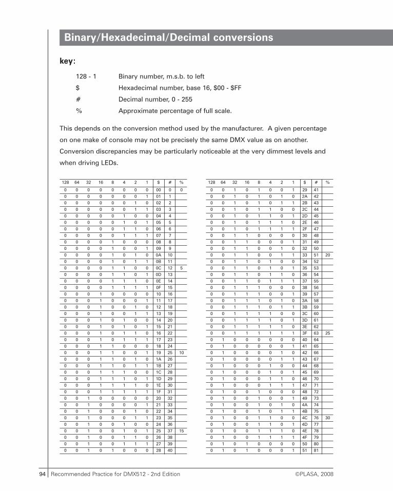
94 Recommended Practice for DMX512 - 2nd Edition ©PLASA, 2008
128 64 32 16 8 4 2 1 $ # %
0 0 0 0 0 0 0 0 00 0 0
0 0 0 0 0 0 0 1 01 1
0 0 0 0 0 0 1 0 02 2
0 0 0 0 0 0 1 1 03 3
0 0 0 0 0 1 0 0 04 4
0 0 0 0 0 1 0 1 05 5
0 0 0 0 0 1 1 0 06 6
0 0 0 0 0 1 1 1 07 7
0 0 0 0 1 0 0 0 08 8
0 0 0 0 1 0 0 1 09 9
0 0 0 0 1 0 1 0 0A 10
0 0 0 0 1 0 1 1 0B 11
0 0 0 0 1 1 0 0 0C 12 5
0 0 0 0 1 1 0 1 0D 13
0 0 0 0 1 1 1 0 0E 14
0 0 0 0 1 1 1 1 0F 15
0 0 0 1 0 0 0 0 10 16
0 0 0 1 0 0 0 1 11 17
0 0 0 1 0 0 1 0 12 18
0 0 0 1 0 0 1 1 13 19
0 0 0 1 0 1 0 0 14 20
0 0 0 1 0 1 0 1 15 21
0 0 0 1 0 1 1 0 16 22
0 0 0 1 0 1 1 1 17 23
0 0 0 1 1 0 0 0 18 24
0 0 0 1 1 0 0 1 19 25 10
0 0 0 1 1 0 1 0 1A 26
0 0 0 1 1 0 1 1 1B 27
0 0 0 1 1 1 0 0 1C 28
0 0 0 1 1 1 0 1 1D 29
0 0 0 1 1 1 1 0 1E 30
0 0 0 1 1 1 1 1 1F 31
0 0 1 0 0 0 0 0 20 32
0 0 1 0 0 0 0 1 21 33
0 0 1 0 0 0 1 0 22 34
0 0 1 0 0 0 1 1 23 35
0 0 1 0 0 1 0 0 24 36
0 0 1 0 0 1 0 1 25 37 15
0 0 1 0 0 1 1 0 26 38
0 0 1 0 0 1 1 1 27 39
0 0 1 0 1 0 0 0 28 40
128 64 32 16 8 4 2 1 $ # %
0 0 1 0 1 0 0 1 29 41
0 0 1 0 1 0 1 0 2A 42
0 0 1 0 1 0 1 1 2B 43
0 0 1 0 1 1 0 0 2C 44
0 0 1 0 1 1 0 1 2D 45
0 0 1 0 1 1 1 0 2E 46
0 0 1 0 1 1 1 1 2F 47
0 0 1 1 0 0 0 0 30 48
0 0 1 1 0 0 0 1 31 49
0 0 1 1 0 0 1 0 32 50
0 0 1 1 0 0 1 1 33 51 20
0 0 1 1 0 1 0 0 34 52
0 0 1 1 0 1 0 1 35 53
0 0 1 1 0 1 1 0 36 54
0 0 1 1 0 1 1 1 37 55
0 0 1 1 1 0 0 0 38 56
0 0 1 1 1 0 0 1 39 57
0 0 1 1 1 0 1 0 3A 58
0 0 1 1 1 0 1 1 3B 59
0 0 1 1 1 1 0 0 3C 60
0 0 1 1 1 1 0 1 3D 61
0 0 1 1 1 1 1 0 3E 62
0 0 1 1 1 1 1 1 3F 63 25
0 1 0 0 0 0 0 0 40 64
0 1 0 0 0 0 0 1 41 65
0 1 0 0 0 0 1 0 42 66
0 1 0 0 0 0 1 1 43 67
0 1 0 0 0 1 0 0 44 68
0 1 0 0 0 1 0 1 45 69
0 1 0 0 0 1 1 0 46 70
0 1 0 0 0 1 1 1 47 71
0 1 0 0 1 0 0 0 48 72
0 1 0 0 1 0 0 1 49 73
0 1 0 0 1 0 1 0 4A 74
0 1 0 0 1 0 1 1 4B 75
0 1 0 0 1 1 0 0 4C 76 30
0 1 0 0 1 1 0 1 4D 77
0 1 0 0 1 1 1 0 4E 78
0 1 0 0 1 1 1 1 4F 79
0 1 0 1 0 0 0 0 50 80
0 1 0 1 0 0 0 1 51 81
Binary/Hexadecimal/Decimal conversions
key:
128 - 1 Binary number, m.s.b. to left
$ Hexadecimal number, base 16, $00 - $FF
# Decimal number, 0 - 255
% Approximate percentage of full scale.
This depends on the conversion method used by the manufacturer. A given percentage
on one make of console may not be precisely the same DMX value as on another.
Conversion discrepancies may be particularly noticeable at the very dimmest levels and
when driving LEDs.
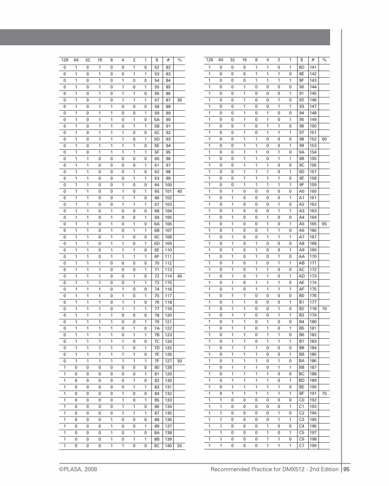
95Recommended Practice for DMX512 - 2nd Edition©PLASA, 2008
128 64 32 16 8 4 2 1 $ # %
0 1 0 1 0 0 1 0 52 82
0 1 0 1 0 0 1 1 53 83
0 1 0 1 0 1 0 0 54 84
0 1 0 1 0 1 0 1 55 85
0 1 0 1 0 1 1 0 56 86
0 1 0 1 0 1 1 1 57 87 35
0 1 0 1 1 0 0 0 58 88
0 1 0 1 1 0 0 1 59 89
0 1 0 1 1 0 1 0 5A 90
0 1 0 1 1 0 1 1 5B 91
0 1 0 1 1 1 0 0 5C 92
0 1 0 1 1 1 0 1 5D 93
0 1 0 1 1 1 1 0 5E 94
0 1 0 1 1 1 1 1 5F 95
0 1 1 0 0 0 0 0 60 96
0 1 1 0 0 0 0 1 61 97
0 1 1 0 0 0 1 0 62 98
0 1 1 0 0 0 1 1 63 99
0 1 1 0 0 1 0 0 64 100
0 1 1 0 0 1 0 1 65 101 40
0 1 1 0 0 1 1 0 66 102
0 1 1 0 0 1 1 1 67 103
0 1 1 0 1 0 0 0 68 104
0 1 1 0 1 0 0 1 69 105
0 1 1 0 1 0 1 0 6A 106
0 1 1 0 1 0 1 1 6B 107
0 1 1 0 1 1 0 0 6C 108
0 1 1 0 1 1 0 1 6D 109
0 1 1 0 1 1 1 0 6E 110
0 1 1 0 1 1 1 1 6F 111
0 1 1 1 0 0 0 0 70 112
0 1 1 1 0 0 0 1 71 113
0 1 1 1 0 0 1 0 72 114 45
0 1 1 1 0 0 1 1 73 115
0 1 1 1 0 1 0 0 74 116
0 1 1 1 0 1 0 1 75 117
0 1 1 1 0 1 1 0 76 118
0 1 1 1 0 1 1 1 77 119
0 1 1 1 1 0 0 0 78 120
0 1 1 1 1 0 0 1 79 121
0 1 1 1 1 0 1 0 7A 122
0 1 1 1 1 0 1 1 7B 123
0 1 1 1 1 1 0 0 7C 124
0 1 1 1 1 1 0 1 7D 125
0 1 1 1 1 1 1 0 7E 126
0 1 1 1 1 1 1 1 7F 127 50
1 0 0 0 0 0 0 0 80 128
1 0 0 0 0 0 0 1 81 129
1 0 0 0 0 0 1 0 82 130
1 0 0 0 0 0 1 1 83 131
1 0 0 0 0 1 0 0 84 132
1 0 0 0 0 1 0 1 85 133
1 0 0 0 0 1 1 0 86 134
1 0 0 0 0 1 1 1 87 135
1 0 0 0 1 0 0 0 88 136
1 0 0 0 1 0 0 1 89 137
1 0 0 0 1 0 1 0 8A 138
1 0 0 0 1 0 1 1 8B 139
1 0 0 0 1 1 0 0 8C 140 55
128 64 32 16 8 4 2 1 $ # %
1 0 0 0 1 1 0 1 8D 141
1 0 0 0 1 1 1 0 8E 142
1 0 0 0 1 1 1 1 8F 143
1 0 0 1 0 0 0 0 90 144
1 0 0 1 0 0 0 1 91 145
1 0 0 1 0 0 1 0 92 146
1 0 0 1 0 0 1 1 93 147
1 0 0 1 0 1 0 0 94 148
1 0 0 1 0 1 0 1 95 149
1 0 0 1 0 1 1 0 96 150
1 0 0 1 0 1 1 1 97 151
1 0 0 1 1 0 0 0 98 152 60
1 0 0 1 1 0 0 1 99 153
1 0 0 1 1 0 1 0 9A 154
1 0 0 1 1 0 1 1 9B 155
1 0 0 1 1 1 0 0 9C 156
1 0 0 1 1 1 0 1 9D 157
1 0 0 1 1 1 1 0 9E 158
1 0 0 1 1 1 1 1 9F 159
1 0 1 0 0 0 0 0 A0 160
1 0 1 0 0 0 0 1 A1 161
1 0 1 0 0 0 1 0 A2 162
1 0 1 0 0 0 1 1 A3 163
1 0 1 0 0 1 0 0 A4 164
1 0 1 0 0 1 0 1 A5 165 65
1 0 1 0 0 1 1 0 A6 166
1 0 1 0 0 1 1 1 A7 167
1 0 1 0 1 0 0 0 A8 168
1 0 1 0 1 0 0 1 A9 169
1 0 1 0 1 0 1 0 AA 170
1 0 1 0 1 0 1 1 AB 171
1 0 1 0 1 1 0 0 AC 172
1 0 1 0 1 1 0 1 AD 173
1 0 1 0 1 1 1 0 AE 174
1 0 1 0 1 1 1 1 AF 175
1 0 1 1 0 0 0 0 B0 176
1 0 1 1 0 0 0 1 B1 177
1 0 1 1 0 0 1 0 B2 178 70
1 0 1 1 0 0 1 1 B3 179
1 0 1 1 0 1 0 0 B4 180
1 0 1 1 0 1 0 1 B5 181
1 0 1 1 0 1 1 0 B6 182
1 0 1 1 0 1 1 1 B7 183
1 0 1 1 1 0 0 0 B8 184
1 0 1 1 1 0 0 1 B9 185
1 0 1 1 1 0 1 0 BA 186
1 0 1 1 1 0 1 1 BB 187
1 0 1 1 1 1 0 0 BC 188
1 0 1 1 1 1 0 1 BD 189
1 0 1 1 1 1 1 0 BE 190
1 0 1 1 1 1 1 1 BF 191 75
1 1 0 0 0 0 0 0 C0 192
1 1 0 0 0 0 0 1 C1 193
1 1 0 0 0 0 1 0 C2 194
1 1 0 0 0 0 1 1 C3 195
1 1 0 0 0 1 0 0 C4 196
1 1 0 0 0 1 0 1 C5 197
1 1 0 0 0 1 1 0 C6 198
1 1 0 0 0 1 1 1 C7 199
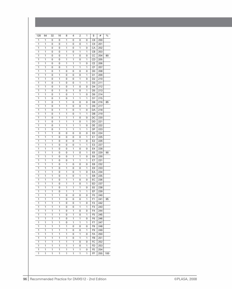
96 Recommended Practice for DMX512 - 2nd Edition ©PLASA, 2008
128 64 32 16 8 4 2 1 $ # %
1 1 0 0 1 0 0 0 C8 200
1 1 0 0 1 0 0 1 C9 201
1 1 0 0 1 0 1 0 CA 202
1 1 0 0 1 0 1 1 CB 203
1 1 0 0 1 1 0 0 CC 204 80
1 1 0 0 1 1 0 1 CD 205
1 1 0 0 1 1 1 0 CE 206
1 1 0 0 1 1 1 1 CF 207
1 1 0 1 0 0 0 0 D0 208
1 1 0 1 0 0 0 1 D1 209
1 1 0 1 0 0 1 0 D2 210
1 1 0 1 0 0 1 1 D3 211
1 1 0 1 0 1 0 0 D4 212
1 1 0 1 0 1 0 1 D5 213
1 1 0 1 0 1 1 0 D6 214
1 1 0 1 0 1 1 1 D7 215
1 1 0 1 1 0 0 0 D8 216 85
1 1 0 1 1 0 0 1 D9 217
1 1 0 1 1 0 1 0 DA 218
1 1 0 1 1 0 1 1 DB 219
1 1 0 1 1 1 0 0 DC 220
1 1 0 1 1 1 0 1 DD 221
1 1 0 1 1 1 1 0 DE 222
1 1 0 1 1 1 1 1 DF 223
1 1 1 0 0 0 0 0 E0 224
1 1 1 0 0 0 0 1 E1 225
1 1 1 0 0 0 1 0 E2 226
1 1 1 0 0 0 1 1 E3 227
1 1 1 0 0 1 0 0 E4 228
1 1 1 0 0 1 0 1 E5 229 90
1 1 1 0 0 1 1 0 E6 230
1 1 1 0 0 1 1 1 E7 231
1 1 1 0 1 0 0 0 E8 232
1 1 1 0 1 0 0 1 E9 233
1 1 1 0 1 0 1 0 EA 234
1 1 1 0 1 0 1 1 EB 235
1 1 1 0 1 1 0 0 EC 236
1 1 1 0 1 1 0 1 ED 237
1 1 1 0 1 1 1 0 EE 238
1 1 1 0 1 1 1 1 EF 239
1 1 1 1 0 0 0 0 F0 240
1 1 1 1 0 0 0 1 F1 241 95
1 1 1 1 0 0 1 0 F2 242
1 1 1 1 0 0 1 1 F3 243
1 1 1 1 0 1 0 0 F4 244
1 1 1 1 0 1 0 1 F5 245
1 1 1 1 0 1 1 0 F6 246
1 1 1 1 0 1 1 1 F7 247
1 1 1 1 1 0 0 0 F8 248
1 1 1 1 1 0 0 1 F9 249
1 1 1 1 1 0 1 0 FA 250
1 1 1 1 1 0 1 1 FB 251
1 1 1 1 1 1 0 0 FC 252
1 1 1 1 1 1 0 1 FD 253
1 1 1 1 1 1 1 0 FE 254
1 1 1 1 1 1 1 1 FF 255 100
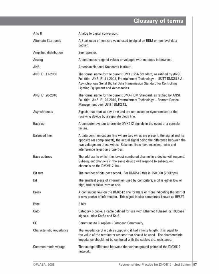
97Recommended Practice for DMX512 - 2nd Edition©PLASA, 2008
Glossary of terms
A to D Analog to digital conversion.
Alternate Start code A Start code of non-zero value used to signal an RDM or non-level data packet.
Amplifier, distribution See repeater.
Analog A continuous range of values or voltages with no steps in between.
ANSI American National Standards Institute.
ANSI E1.11-2008 The formal name for the current DMX512-A Standard, as ratified by ANSI. Full title: ANSI E1.11-2008, Entertainment Technology -- USITT DMX512-A --Asynchronous Serial Digital Data Transmission Standard for Controlling Lighting Equipment and Accessories.
ANSI E1.20-2010 The formal name for the current DMX-RDM Standard, as ratified by ANSI. Full title: ANSI E1.20-2010, Entertainment Technology -- Remote Device Management over USITT DMX512.
Asynchronous Signals that start at any time and are not locked or synchronised to thereceiving device by a separate clock line.
Back-up A computer system to provide DMX512 signals in the event of a console failure.
Balanced line A data communications line where two wires are present, the signal and its opposite (or complement), the actual signal being the difference between thetwo voltages on these wires. Balanced lines have excellent noise and interference rejection properties.
Base address The address to which the lowest numbered channel in a device will respond.Subsequent channels in the same device will respond to subsequent channels on the DMX512 link.
Bit rate The number of bits per second. For DMX512 this is 250,000 (250kbps).
Bit The smallest piece of information used by computers, a bit is either low or high, true or false, zero or one.
Break A continuous low on the DMX512 line for 88μs or more indicating the start ofa new packet of information. This signal is also sometimes known as RESET.
Byte 8 bits.
Cat5 Category 5 cable, a cable defined for use with Ethernet 10baseT or 100baseTsignals. Also Cat5e and Cat6.
CE Communauté Européen - European Community.
Characteristic impedance The impedance of a cable supposing it had infinite length. It is equal to the value of the terminator resistor that should be used. The characteristic impedance should not be confused with the cable’s d.c. resistance.
Common-mode voltage The voltage difference between the various ground points of the DMX512 network.
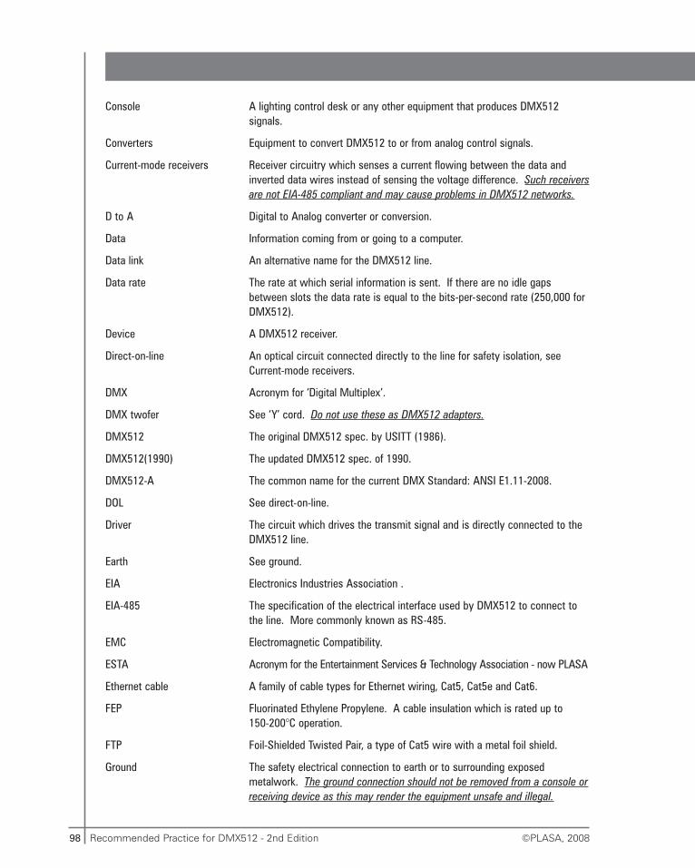
98 Recommended Practice for DMX512 - 2nd Edition ©PLASA, 2008
Console A lighting control desk or any other equipment that produces DMX512 signals.
Converters Equipment to convert DMX512 to or from analog control signals.
Current-mode receivers Receiver circuitry which senses a current flowing between the data and inverted data wires instead of sensing the voltage difference. Such receiversare not EIA-485 compliant and may cause problems in DMX512 networks.
D to A Digital to Analog converter or conversion.
Data Information coming from or going to a computer.
Data link An alternative name for the DMX512 line.
Data rate The rate at which serial information is sent. If there are no idle gaps between slots the data rate is equal to the bits-per-second rate (250,000 for DMX512).
Device A DMX512 receiver.
Direct-on-line An optical circuit connected directly to the line for safety isolation, see Current-mode receivers.
DMX Acronym for ‘Digital Multiplex’.
DMX twofer See ‘Y’ cord. Do not use these as DMX512 adapters.
DMX512 The original DMX512 spec. by USITT (1986).
DMX512(1990) The updated DMX512 spec. of 1990.
DMX512-A The common name for the current DMX Standard: ANSI E1.11-2008.
DOL See direct-on-line.
Driver The circuit which drives the transmit signal and is directly connected to the DMX512 line.
Earth See ground.
EIA Electronics Industries Association .
EIA-485 The specification of the electrical interface used by DMX512 to connect to the line. More commonly known as RS-485.
EMC Electromagnetic Compatibility.
ESTA Acronym for the Entertainment Services & Technology Association - now PLASA
Ethernet cable A family of cable types for Ethernet wiring, Cat5, Cat5e and Cat6.
FEP Fluorinated Ethylene Propylene. A cable insulation which is rated up to 150-200°C operation.
FTP Foil-Shielded Twisted Pair, a type of Cat5 wire with a metal foil shield.
Ground The safety electrical connection to earth or to surrounding exposed metalwork. The ground connection should not be removed from a console orreceiving device as this may render the equipment unsafe and illegal.
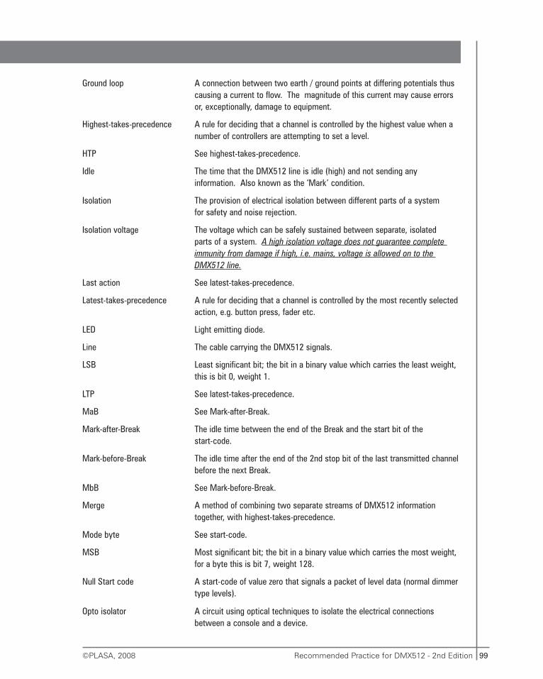
99Recommended Practice for DMX512 - 2nd Edition©PLASA, 2008
Ground loop A connection between two earth / ground points at differing potentials thus causing a current to flow. The magnitude of this current may cause errors or, exceptionally, damage to equipment.
Highest-takes-precedence A rule for deciding that a channel is controlled by the highest value when a number of controllers are attempting to set a level.
HTP See highest-takes-precedence.
Idle The time that the DMX512 line is idle (high) and not sending any information. Also known as the ‘Mark’ condition.
Isolation The provision of electrical isolation between different parts of a system for safety and noise rejection.
Isolation voltage The voltage which can be safely sustained between separate, isolated parts of a system. A high isolation voltage does not guarantee complete immunity from damage if high, i.e. mains, voltage is allowed on to the DMX512 line.
Last action See latest-takes-precedence.
Latest-takes-precedence A rule for deciding that a channel is controlled by the most recently selected action, e.g. button press, fader etc.
LED Light emitting diode.
Line The cable carrying the DMX512 signals.
LSB Least significant bit; the bit in a binary value which carries the least weight, this is bit 0, weight 1.
LTP See latest-takes-precedence.
MaB See Mark-after-Break.
Mark-after-Break The idle time between the end of the Break and the start bit of the start-code.
Mark-before-Break The idle time after the end of the 2nd stop bit of the last transmitted channelbefore the next Break.
MbB See Mark-before-Break.
Merge A method of combining two separate streams of DMX512 information together, with highest-takes-precedence.
Mode byte See start-code.
MSB Most significant bit; the bit in a binary value which carries the most weight, for a byte this is bit 7, weight 128.
Null Start code A start-code of value zero that signals a packet of level data (normal dimmer type levels).
Opto isolator A circuit using optical techniques to isolate the electrical connections between a console and a device.
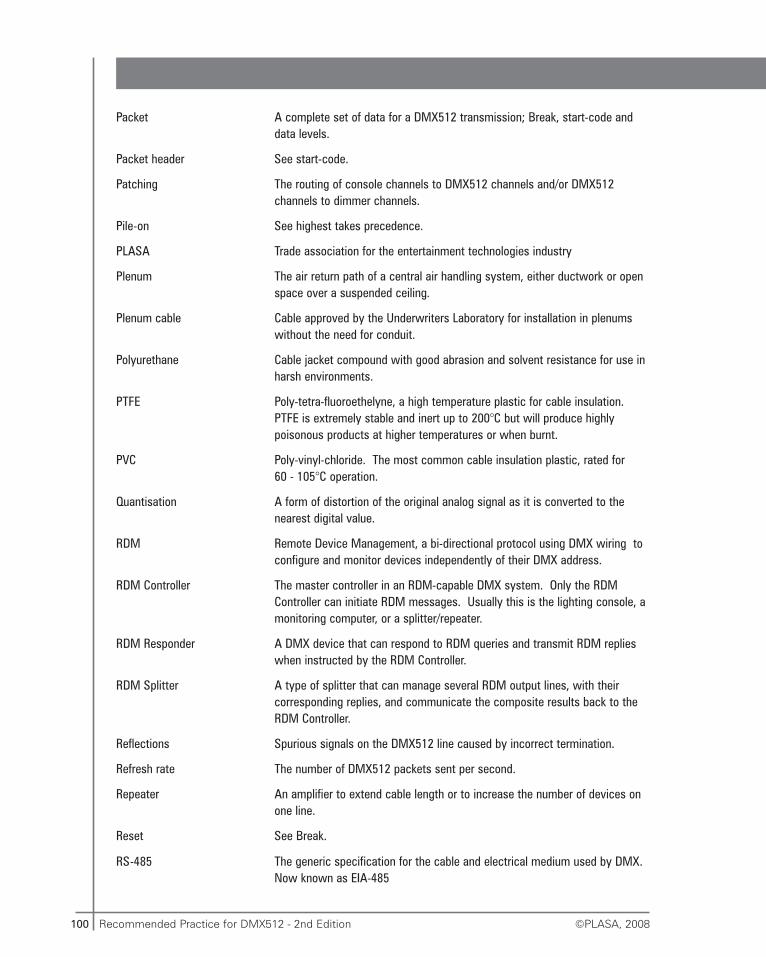
100 Recommended Practice for DMX512 - 2nd Edition ©PLASA, 2008
Packet A complete set of data for a DMX512 transmission; Break, start-code and data levels.
Packet header See start-code.
Patching The routing of console channels to DMX512 channels and/or DMX512 channels to dimmer channels.
Pile-on See highest takes precedence.
PLASA Trade association for the entertainment technologies industry
Plenum The air return path of a central air handling system, either ductwork or open space over a suspended ceiling.
Plenum cable Cable approved by the Underwriters Laboratory for installation in plenums without the need for conduit.
Polyurethane Cable jacket compound with good abrasion and solvent resistance for use in harsh environments.
PTFE Poly-tetra-fluoroethelyne, a high temperature plastic for cable insulation. PTFE is extremely stable and inert up to 200°C but will produce highly poisonous products at higher temperatures or when burnt.
PVC Poly-vinyl-chloride. The most common cable insulation plastic, rated for 60 - 105°C operation.
Quantisation A form of distortion of the original analog signal as it is converted to the nearest digital value.
RDM Remote Device Management, a bi-directional protocol using DMX wiring to configure and monitor devices independently of their DMX address.
RDM Controller The master controller in an RDM-capable DMX system. Only the RDM Controller can initiate RDM messages. Usually this is the lighting console, a monitoring computer, or a splitter/repeater.
RDM Responder A DMX device that can respond to RDM queries and transmit RDM replies when instructed by the RDM Controller.
RDM Splitter A type of splitter that can manage several RDM output lines, with their corresponding replies, and communicate the composite results back to the RDM Controller.
Reflections Spurious signals on the DMX512 line caused by incorrect termination.
Refresh rate The number of DMX512 packets sent per second.
Repeater An amplifier to extend cable length or to increase the number of devices on one line.
Reset See Break.
RS-485 The generic specification for the cable and electrical medium used by DMX. Now known as EIA-485
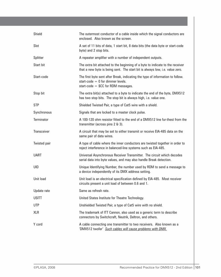
101Recommended Practice for DMX512 - 2nd Edition©PLASA, 2008
Shield The outermost conductor of a cable inside which the signal conductors are enclosed. Also known as the screen.
Slot A set of 11 bits of data, 1 start bit, 8 data bits (the data byte or start-code byte) and 2 stop bits.
Splitter A repeater amplifier with a number of independent outputs.
Start bit The extra bit attached to the beginning of a byte to indicate to the receiver that a new byte is being sent. The start bit is always low, i.e. value zero.
Start-code The first byte sent after Break, indicating the type of information to follow.start-code = 0 for dimmer levels.start-code = $CC for RDM messages.
Stop bit The extra bit(s) attached to a byte to indicate the end of the byte, DMX512 has two stop bits. The stop bit is always high, i.e. value one.
STP Shielded Twisted Pair, a type of Cat5 wire with a shield.
Synchronous Signals that are locked to a master clock pulse.
Terminator A 100-120 ohm resistor fitted to the end of a DMX512 line fur-thest from thetransmitter (across pins 2 & 3).
Transceiver A circuit that may be set to either transmit or receive EIA-485 data on the same pair of data wires.
Twisted pair A type of cable where the inner conductors are twisted together in order to reject interference in balanced-line systems such as EIA-485.
UART Universal Asynchronous Receiver Transmitter. The circuit which decodes serial data into byte values, and may also handle Break detection.
UID Unique Identifying Number, the number used by RDM to send a message to a device independently of its DMX address setting.
Unit load Unit load is an electrical specification defined by EIA-485. Most receiver circuits present a unit load of between 0.6 and 1.
Update rate Same as refresh rate.
USITT United States Institute for Theatre Technology.
UTP Unshielded Twisted Pair, a type of Cat5 wire with no shield.
XLR The trademark of ITT Cannon, also used as a generic term to describe connectors by Switchcraft, Neutrik, Deltron, and others.
Y cord A cable connecting one transmitter to two receivers. Also known as a ‘DMX512 twofer’ Such cables will cause problems with DMX.
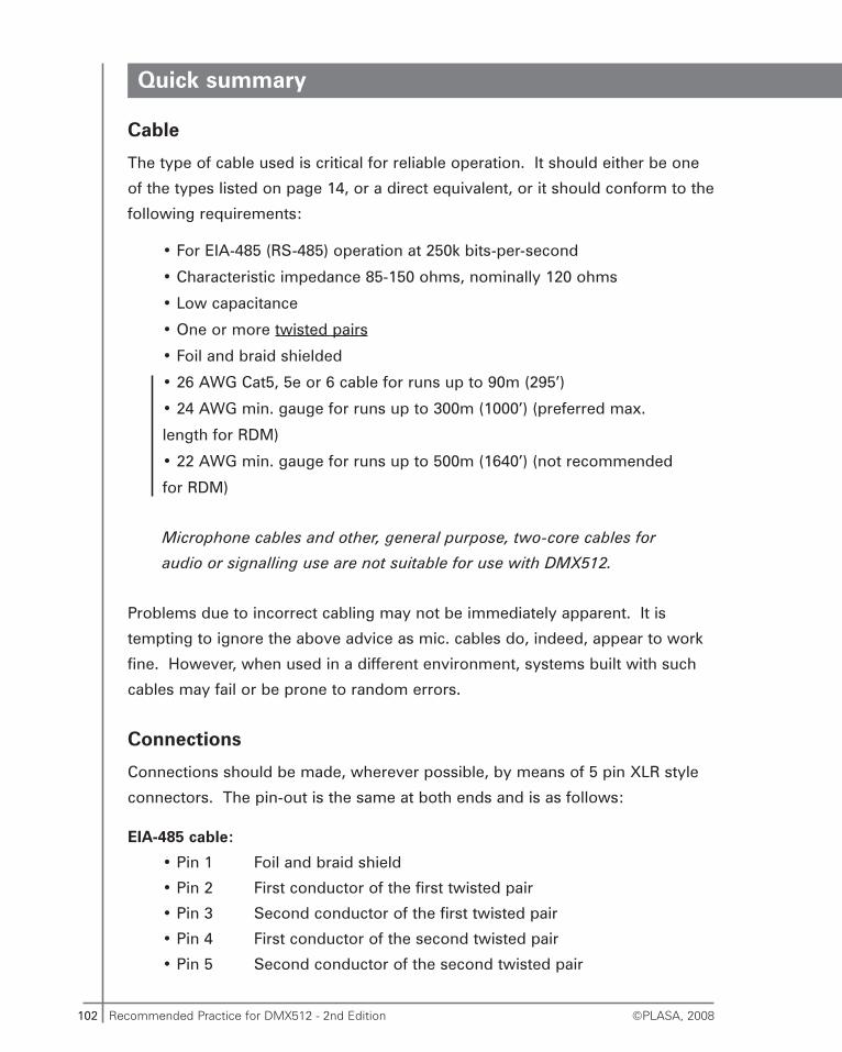
102 Recommended Practice for DMX512 - 2nd Edition ©PLASA, 2008
Quick summary
Cable
The type of cable used is critical for reliable operation. It should either be one
of the types listed on page 14, or a direct equivalent, or it should conform to the
following requirements:
• For EIA-485 (RS-485) operation at 250k bits-per-second
• Characteristic impedance 85-150 ohms, nominally 120 ohms
• Low capacitance
• One or more twisted pairs
• Foil and braid shielded
• 26 AWG Cat5, 5e or 6 cable for runs up to 90m (295’)
• 24 AWG min. gauge for runs up to 300m (1000’) (preferred max.
length for RDM)
• 22 AWG min. gauge for runs up to 500m (1640’) (not recommended
for RDM)
Microphone cables and other, general purpose, two-core cables for
audio or signalling use are not suitable for use with DMX512.
Problems due to incorrect cabling may not be immediately apparent. It is
tempting to ignore the above advice as mic. cables do, indeed, appear to work
fine. However, when used in a different environment, systems built with such
cables may fail or be prone to random errors.
Connections
Connections should be made, wherever possible, by means of 5 pin XLR style
connectors. The pin-out is the same at both ends and is as follows:
EIA-485 cable:
• Pin 1 Foil and braid shield
• Pin 2 First conductor of the first twisted pair
• Pin 3 Second conductor of the first twisted pair
• Pin 4 First conductor of the second twisted pair
• Pin 5 Second conductor of the second twisted pair
103Recommended Practice for DMX512 - 2nd Edition©PLASA, 2008
First, don’t forget to pass the cable through the connector shell!
Separate the shield from the inner conductors and cut it back about 12mm (½").
Attach a short wire to the shield and solder to pin 1, or use the drain wire if one
is provided. Insulate any exposed shield strands and then solder the remaining
4 inner conductors.
Fit an insulator or PVC tape around the outside of the group of five pins. It is
important to prevent the connector shell from contacting any of the pins,
including the shield.
The second pair, on pins 4 and 5 is optional and is not required in basic
DMX512 systems. Nevertheless, it is advisable to fit a 2-pair cable, with all the
pins connected, wherever possible.
Cat5, 5e or 6 cable (Ethernet cable) in 5 pin XLR
• Pin 1 White/Brown & Brown (together)
• Pin 2 Orange
• Pin 3 White/Orange
• Pin 4 Green
• Pin 5 White/Green
• If a foil (FTP cable) or braid (STP cable) shield is provided it should be
connected to pin 1 along with the white/brown and brown wires.
Cat5, 5e or 6 cable in IEC60603-7 (RJ45) connector
• Pin 1 White/Orange
• Pin 2 Orange
• Pin 3 White/Green
• Pin 4 Blue
• Pin 5 White/Blue
• Pin 6 Green
• Pin 7 White/Brown
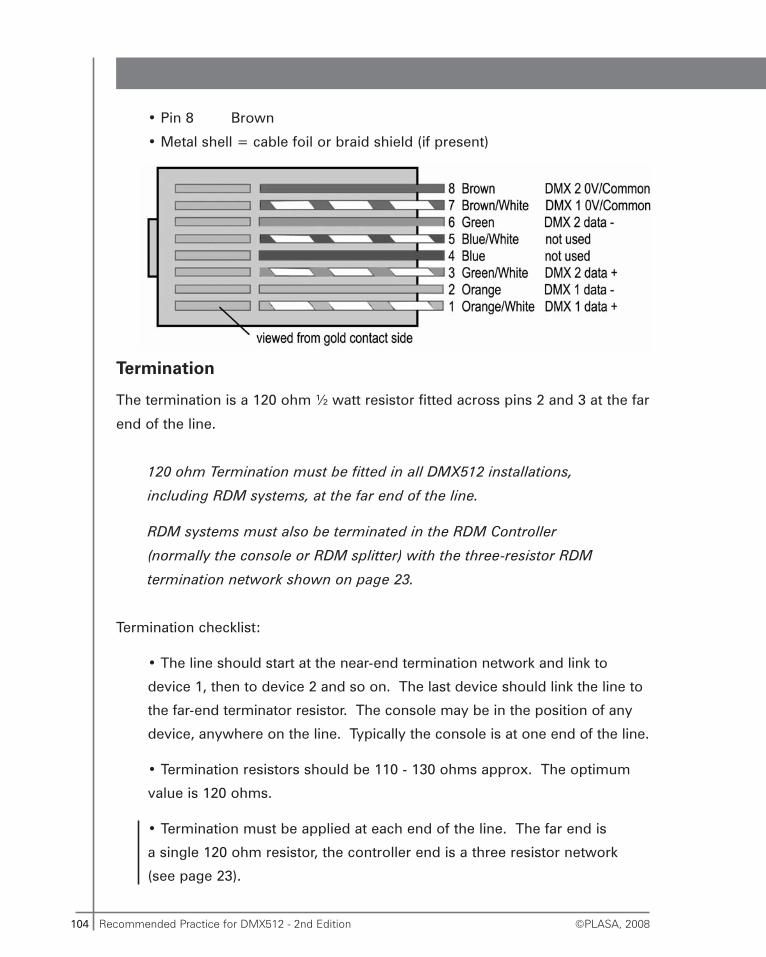
104 Recommended Practice for DMX512 - 2nd Edition ©PLASA, 2008
• Pin 8 Brown
• Metal shell = cable foil or braid shield (if present)
Termination
The termination is a 120 ohm ½ watt resistor fitted across pins 2 and 3 at the far
end of the line.
120 ohm Termination must be fitted in all DMX512 installations,
including RDM systems, at the far end of the line.
RDM systems must also be terminated in the RDM Controller
(normally the console or RDM splitter) with the three-resistor RDM
termination network shown on page 23.
Termination checklist:
• The line should start at the near-end termination network and link to
device 1, then to device 2 and so on. The last device should link the line to
the far-end terminator resistor. The console may be in the position of any
device, anywhere on the line. Typically the console is at one end of the line.
• Termination resistors should be 110 - 130 ohms approx. The optimum
value is 120 ohms.
• Termination must be applied at each end of the line. The far end is
a single 120 ohm resistor, the controller end is a three resistor network
(see page 23).
105Recommended Practice for DMX512 - 2nd Edition©PLASA, 2008
• Only pins 2 and 3 are connected to the far-end termination resistor.
• Some devices feature a ‘termination’, ‘end-of-line’ or ‘last-rack’ switch.
When many such devices are connected to the line it is most important to
check that only the devices at the far end of each line have their switches set.
• RDM systems require a line biasing termination network in the console
as part of the console-end termination. Ensure that any RDM biasing
option or switch is selected on one device only on each DMX512-A line.
• A common far-end terminator is a line male XLR connector with the
resistor fitted inside. This ‘dummy’ plug is connected to the output of the
last device on the line.
DMX512 line routing
• DMX512 lines can only be run as a daisy-chain. The line jumps from the
console to one device and then to the next device and so on.
• Only 32 devices may be connected to one line.
• Devices may be connected to the line at any point along its length
DMX512 lines cannot be split into branches by making up simple
‘twofer’ adapter leads (Y cords).
If DMX512 signals must be sent in different directions then you must use
a splitter amplifier. The amplifier will require a separate output for each branch
that you need to provide.
If the DMX system operates RDM the repeater or splitter amplifiers must be
RDM capable. Normal splitters will not work. Lines fed from splitter amplifiers
must all be treated individually as new DMX512 lines. Each will require
a termination resistor at each end of the line. The near-end (transmitter end) of
each line will also require an RDM biasing network to be connected. Each will
be subject to the same limit of a maximum of 32 devices.
106 Recommended Practice for DMX512 - 2nd Edition ©PLASA, 2008
Physical layout
The EIA-485 medium used by DMX512 is very robust. However, it is worth
taking extra care with your cable routing:
• Avoid long parallel runs with power cables.
• Avoid dimmer load cables wherever possible.
(Crossovers of power and load cables are acceptable)
• Avoid locations where the cable may degrade over time. Alternatively,
choose a suitably resistant cable.
• Use a strong cable and provide adequate support. Some cables are
fitted with a core of high-tensile fibres.
• If the cable is likely to come into contact with hot objects, such as
luminaires, choose a type with either PTFE, FEP or Polyurethane jacket.
Isolation
The EIA-485 system, by which DMX512 signals are sent, can in some
circumstances suffer from problems due to equipment grounding. This effect is
similar to the ‘hum loop’ problem with audio equipment when multiple units are
connected to mains ground.
If the grounds of all the devices are not at exactly the same potential (voltage)
then a current may flow down the shield between devices. This current, if large
enough, can cause errors and exceptionally, destruction of DMX512
transmitters and receivers.
In small systems this is most unlikely to be a problem. In larger systems it is
advisable to isolate some, or all of the devices from each other and/or from the
console. The fewer devices there are on each separate branch of DMX from
a splitter, the less equipment is affected by a line failure.
It is strongly recommended that optical isolation is fitted where practical or that
devices are chosen that feature built-in optical isolation.
107Recommended Practice for DMX512 - 2nd Edition©PLASA, 2008
It is easy to isolate devices by means of an opto-isolator amplifier. These are
available from many manufacturers of DMX512 equipment throughout the
world.
Identification of isolated equipment can be carried out by means of a continuity
tester:
• Measure the resistance between pin 1 of a device’s input connector and
the mains ground for that device. If the measurement shows open-circuit,
or very high resistance then the device is isolated.
• In the case of converters that accept DMX and produce a new signal of
another type, for instance analog, measure the continuity from the DMX
input pin 1 to the output zero-volt or return connection.
Although a converter may measure as isolated from the mains earth it may
become earthed/grounded once its output is connected on to downstream
equipment.
See page 64 for more details of tests for ground-loops (common mode voltage
tests) and isolation.
RDM systems
In a DMX system employing RDM or bi-directional features ordinary
Repeaters, Splitters and Opto-isolators will not support RDM
messages. They will still work for sending conventional level data
only. Special types suitable for DMX512-RDM must be used for RDM.
RDM messages may need to be disabled in a console or controller if
RDM devices are connected downstream of non-RDM-capable in-line
equipment. Failure to prevent RDM transmission in this case could
result in system malfunction.
108 Recommended Practice for DMX512 - 2nd Edition ©PLASA, 2008
Equipment incompatibility, who is to blame?
For normal (non RDM) operation there are only a few common ways
a transmitter can be non-compliant with the DMX specification and cause
malfunction:
1. Transmission bits-per-second rate not accurately 250,000
2. Break too short
3. Mark-after-Break too short
4. Too few channels and too high refresh rate
5. Not enough drive power, cannot reach minimum signalling voltages
If the transmitter adheres correctly to these rules then any incompatibility,
failure to read the data properly or at all, is nearly always the fault of the
receiver or the wiring network.
If you directly connect a transmitter to a device with a short DMX cable, known
to be working and correctly wired, and the receiver is unable to keep pace with
the transmissions, and you are sure the transmitter meets the five key points
shown above then it is likely that the receiver is non-compliant for DMX in
some way.
Receivers have a responsibility to correctly decode DMX level data
sent at any rate between the minimum and maximum allowed values.
Receivers must also check the Start code to ensure they do not
incorrectly interpret RDM messages as dimmer level data.
109Recommended Practice for DMX512 - 2nd Edition©PLASA, 2008
Useful addresses
PLASA European OfficeRedoubt House1 Edward RoadEastbourneBN23 8ASUnited Kingdomwww.plasa.org
PLASA North American Office630 Ninth AvenueSuite 609New YorkNY 10036U.S.A.www.plasa.org
USITT Inc.315 South Crouse AvenueSuite 200SyracuseNY 13210U.S.A.www.usitt.org
ELECTRONIC INDUSTRIESASSOCIATION (EIA)2500 Wilson BoulevardArlingtonVirginia 22201U.S.Awww.eia.org
AMERICAN NATIONALSTANDARDS INSTITUTE (ANSI)1819 L Street, NW6th floorWashingtonDC 20036U.S.A.www.ansi.org
BELDEN WIRE AND CABLE7701 Forsyth BoulevardSuite 800St. LouisMO 63105U.S.A. www.belden.com
ALPHA WIRE CORPORATION711 Lidgerwood AvePO Box 711ElizabethNJ 07207U.S.A.www.alphawire.com
TMB ASSOCIATES (Proplex cables)10643 Glenoaks BlvdPacoimaCA 91331U.S.A.www.tmb.com
110 Recommended Practice for DMX512 - 2nd Edition ©PLASA, 2008
Recommended reading
This booklet is intended as the concise guide to setting-up a DMX system that
functions. More detail about the ways that DMX may be used, the ways that
controllers operate DMX and in particular the inner technical details of DMX and
RDM may be found in these books:
• Control Freak - by Wayne Howell
• Practical DMX - by Nick Mobsby
• Complete DMX - by James Eade
• Control Systems for Live Entertainment - by John Huntingdon
• Lighting Control: Technology and Applications - by Robert Simpson
• Stage Lighting Controls - by Ulf Sandstrom

Published by | PLASA
Redoubt House, 1 Edward Road
Eastbourne, East Sussex, BN23 8AS, UK.
T: +44 (0)1323 524120
www.plasa.org
Price: $20.00
ISBN: 978-0-9557035-2-2