DMX2PWM 3-channel - Traxon · PDF fileDMX2PWM 3-channel Setup Manual Edition: ... All con-...
20
DMX2PWM 3-channel Setup Manual
Transcript of DMX2PWM 3-channel - Traxon · PDF fileDMX2PWM 3-channel Setup Manual Edition: ... All con-...
DMX2PWM 3-channelSetup Manual

DMX2PWM 3-channel Setup ManualEdition: 06.12.2012 Published by:
Traxon Technologies Europe GmbH Karl Schurz-Strasse 38 Paderborn, Germany ©2012, Traxon Technologies Europe GmbH All rights reserved Comments to: [email protected]

Table of Contents
Safety instructions .................................................................................... 4
Delivery scope .......................................................................................... 5
Installation ................................................................................................ 5
DMX .......................................................................................................... 6Housing version ................................................................................... 6Pin assignment .................................................................................... 7
PCB version connectors........................................................................... 7
Mounting .................................................................................................. 8
Device setup ............................................................................................. 9Manual addressing .............................................................................. 9Auto addressing .................................................................................. 9External power source ....................................................................... 10
Status LEDs ............................................................................................ 10
Dimming curve ....................................................................................... 11
Technical data ........................................................................................ 13Housing version ................................................................................. 13PCB version....................................................................................... 14
Dimensions ............................................................................................. 15Housing version ................................................................................. 15PCB version....................................................................................... 16
Certifications .......................................................................................... 17
Notes ...................................................................................................... 18

4
Setup Manual - DMX2PWM 3-channel
Safety instructions
iOnly use the device in compliance with the environmental conditions specified and watch the technical characteristics. Otherwise the unit may be damaged or malfunction will happen.
iTo prevent the device from overheating, only operate it in well-venti-lated environment. Ventilation may not be obstructed. Do not install next to heat emitting sources or in a place subject to direct sunlight. Overheating damages the device.
Device components inside the system can reach high temperatures! To avoid burns, allow the unit to cool for at least 20 minutes before unmounting or repair.
iInstallation and maintenance of this product must be performed by individuals who are knowledgeable about the procedures, precautions and hazards associated with the product.
iUse a power supply which is compliant to EN55015/EN55022 Class B and EN61000-3-2 Class C for the expected load. The power supply should be equipped with an active PFC circuit for loads higher than 25W.
�For PCB version: the electronic components are sensitive to elec-trostatic discharge (ESD). Hold the PCB only by its edges and be careful not to touch the components. Please do all preparation work on a static-free surface. It is recommended to wear an antistatic wrist strap.

5
Setup Manual - DMX2PWM 3-channel
Delivery scope• DMX2PWM 3ch dimmer 160125 or
DMX2PWM 3ch dimmer PCB version 160124
• Setup Manual (English only)
Housing version only:
• 2-pin screw terminal plug (power supply)
• 6-pin screw terminal plug (LED connection)
InstallationFor the use of the DMX2PWM dimmer device a DC power supply unit is necessary. The choice of the power supply voltage only depends on the supply voltage of your LED fixtures, but must remain in the range from 12V to 48V DC. Please consider that the power supply must be able to provide the current for the connected LED fixtures and the DMX2PWM dimmer. Multiple LED fixtures where each one needs a different voltage level cannot be used with one dimmer device at the same time.
Always select the power supply output voltage accordingly to your LED fixture input voltage: 12V PSU for 12V LEDs, 24V PSU for 24V LEDs, 48V PSU for 48V LEDs.
The “+” line of the Power supply connection (PWR In) is directly routed to the “+” connection of each PWM output. The following picture shows the basic connection scheme:

6
Setup Manual - DMX2PWM 3-channel
The advantage of the above shown type of connection is the reverse supply protection of all LED fixtures and the dimmer itself. Alternatively it is also possible to connect LED fixtures as shown in the figure below.
Make sure that the power supply cables are specified to carry the complete amount of current needed by the connected LED fixtures.
The PWM switching node is designed as a low-side switch and is able to handle a maximum current of 2.5 A. Each output channel is short circuit protected. As soon as an over-current or short circuit situation is detected, the switch of the corre-sponding channel will immediately shut down. The yellow STATUS LED is blinking to signal the over-current error. The dimmer tests the output repeatedly if the over-current still exists. It will re-enable the output as soon as the over-current or short circuit is removed.
DMX
Housing version
A DMX master must be attached to the DMX-In connector. If a valid DMX signal is detected by the DMX2PWM, the green DMX LED is on. To connect multiple devices in a chain, connect the DMX-Out port of the first device to the DMX-In port of the next device. For details about setting up a DMX address, please refer to the cor-responding chapter.

7
Setup Manual - DMX2PWM 3-channel
Pin assignment
Pin Connection
1 DMX-
2 DMX+
3, 7 Gnd
PCB version connectorsThe PCB version has slightly different connectors than the housing version. All con-nectors including the DMX port are screw terminals. Please refer to the figure below when integrating the DMX2PWM PCB version into customized applications.
The DMX GND connection should only be used, if multiple dmx2pwm devices are connected in a chain and are sourced by different power supplies. If you experience data transmission problems in such a configuration, connect all devices in the chain to GND.
8
Setup Manual - DMX2PWM 3-channel
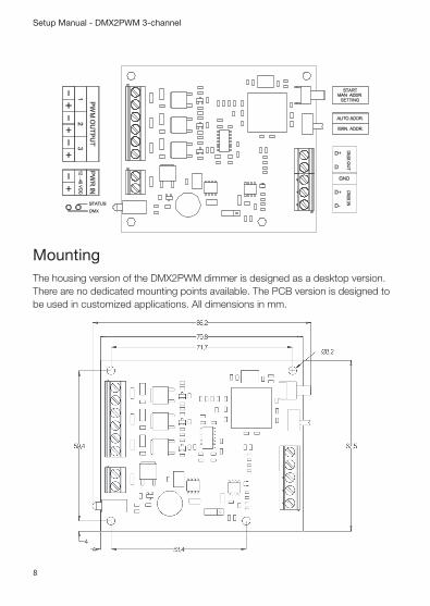
MountingThe housing version of the DMX2PWM dimmer is designed as a desktop version. There are no dedicated mounting points available. The PCB version is designed to be used in customized applications. All dimensions in mm.

9
Setup Manual - DMX2PWM 3-channel
Device setup
Manual addressing
The DMX2PWM dimmer has no switches for setting up the DMX address, instead you configure the first DMX address for the device by sending a DMX data frame. To use manual addressing, the switch must be set to MAN. ADDR.. When you press the button START for at least one second and then release it, the DMX LED starts blinking. The device now listens and waits for a DMX configuration data frame. The first received DMX data byte which is not zero is used as the device’s base address (address of PWM output 1).
Example:
• The first received DMX data byte other than zero is located at address 11 when the device is in listening mode. Address 11 will now be stored as start address for PWM output channel 1. Channels 2 and 3 are then automatically configured the address 12 and 13. The base address is stored into a non-volatile memory so that address is present after repowering the device.
To abort the listening mode without any changes, simply press the button for less than one second. The STATUS LED stops blinking.
To reset the device to base address 1 without sending a configuration data frame, press and hold the button for one second. The DMX LED starts blinking. Then press and hold the button for one second again. The DMX LED stops blinking and the ad-dress is set back to 1. It is of no importance whether the DMX cable is connected or not.
Auto addressing
Auto addressing mode should be used when connecting several DMX2PWM dim-mers in a chain. The first device in a chain occupies the DMX addresses 1, 2 and 3. The next one, which is connected to the DMX-Out connector of the previous one, uses addresses 4, 5 and 6 and so on.
If a base address is already set (see manual address setting), the device also uses this address in auto addressing mode as its base address.

10
Setup Manual - DMX2PWM 3-channel
Examples:
• The first device in the chain has the base address 6 (and also occupies ad-dresses 7 and 8), the next device has the base address 9.
• The first device in the chain has been configured for base address 2 and the next device has the base address 4. The result is that the first device occupies the address 2, 3 and 4 and the next device uses address 8, 9 and 10.
To avoid confusion when using the auto addressing mode it is recommended to reset the base addresses of all devices to 1.
External power source
The housing version of the DMX2PWM is equipped with a jumper (J1) to enable power sourcing on the DMX-In connector pin 5. The default setting at delivery is off (position 2-3). When enabled (position 1-2), the power supply is directly routed to pin 5 of the RJ45 connector. This is especially useful when using the DMX2PWM in combination with the e:cue Glass Touch user terminals. No other additional power supply is needed.
Status LEDs
LED Description
DMX off or flickering No DMX signal recognized or not connected
DMX on DMX present
DMX blinking Awaiting DMX data frame for manual address setting
STATUS off Power supply not connected
STATUS on Normal operation
STATUS blinking Overcurrent detected on one or more channels

11
Setup Manual - DMX2PWM 3-channel
Dimming curve
The dimming of the LEDs is accomplished by a pulse width modulation with a basic frequency of f=488Hz. Due to the 14bit PWM resolution, the “On-time” can be adjusted in 125ns steps. To achieve a more “linear” impression of the LED’s bright-ness, a translation from the 8bit DMX value to the 14bit PWM resolution in form of a dimming curve is implemented.
The following picture shows the principle of PWM dimming. Please keep in mind the DMX2PWM’s switching node is a low-side switch, which means that the LED is on when the (-) connector is switched to GND (low).

12
Setup Manual - DMX2PWM 3-channel
Low-Side switch: low= on, high= off

13
Setup Manual - DMX2PWM 3-channel
Technical data
Housing version
Dimensions mm/inch (WxHxD) 94 x 71,5 x 24 mm/63.66 x 2.81 x 0.94 inch
Weight kg/lbs 0,08 kg/0.176 lbs
Power 12 ... 48 V DC (screw term.)
Power consumption 0.6 W (idle, all channels off, DMX connected)
Max. output current per channel 2.5 A (Overcurrent protection, ±10%)
Max. output load capacitance 1 μF
Over-current retry delay 1 sec.
Minimum on time 2.5 μs
PWM frequency 488 Hz
PWM resolution 14 bit (optimized dimming curve calculated from 8bit DMX value)
Operating/storage temp. -20 ... 80° C /-4 ...176° F
Operating/storage hum. 0 ... 80%, non condensing
Protection class IP20
Housing Aluminium
Certifications CE (EN55015 / EN61547)
Input DMX512 (RJ45)
Outputs DMX512 (RJ45) 3 LED output channels (screw term. + connector: identical to input voltage - connector: low side PWM switch
Data protocols DMX512-A and e:pix
Max. devices in a chain 32 (depends on cable length and quality)
Max. wire cross section 1.5 mm2 (screw terminals, power supply and PWM outputs)

14
Setup Manual - DMX2PWM 3-channel
PCB version
Dimensions mm/inch (WxHxD) 80 x 67,5 x 16 mm/3.15 x 2.66 x 0.63 inch
Weight kg/lbs 0,04 kg/0.088 lbs
Power 12 ... 48 V DC (screw term.)
Power consumption 0.6 W (idle, all channels off, DMX connected)
Max. output current per channel 2.5 A (Overcurrent protection, ±10%)
Max. output load capacitance 1 μF
Over-current retry delay 1 sec.
Minimum on time 2.5 μs
PWM frequency 488 Hz
PWM resolution 14 bit (optimized dimming curve calculated from 8bit DMX value)
Operating/storage temp. -20 ... 80° C /-4 ...176° F
Operating/storage hum. 0 ... 80%, non condensing
Protection class IP20
Housing PCB only
Certifications CE (EN55015/EN61547)
Input DMX512 (screw terminals)
Outputs DMX512 (screw terminals) 3 LED output channels (screw term. + connector: identical to input voltage - connector: low side PWM switch
Data protocols DMX512-A and e:pix
Max. devices in a chain 32 (depends on cable length and quality)
Max. wire cross section 1.5 mm2 (screw terminals, power supply and PWM out

15
Setup Manual - DMX2PWM 3-channel
Dimensions
Housing version
All dimensions in mm and inch.
71,5
/ 2
.81
94 / 3.7
85 / 3.3524
/ 0
.94

16
Setup Manual - DMX2PWM 3-channel
PCB version
All dimensions in mm.

17
Setup Manual - DMX2PWM 3-channel
Certifications
(EN55015/EN61547)
4000805
ETL LISTED Conforms to ANSI/UL Std 60950-1 Certified to CAN/CSA STD C22.2 No. 60950-1

18
Setup Manual - DMX2PWM 3-channel
Notes

19
Setup Manual - DMX2PWM 3-channel

Downloads and more information at www.traxontechnologies.com and www.ecue.com
HONG KONG SHANGHAI TOKYO SINGAPORE ROTTERDAM COLOGNE LONDON
MADRID MILAN PARIS ISTANBUL DENMARK MOSCOW WARSZAWA VIENNA
NEW YORK TORONTO DUBAI BUENOS AIRES MEXICO D.F. SAO PAULO COLOMBIA
MUMBAI
FLEXIBILITY, SIMPLICITY & INNOVATION IN LIGHTING SOLUTIONS & SERVICES