
DMRC ELECTRICAL STANDARDS & DESIGN WING · PDF fileDMRC Electrical Standards & Design Wing...
24
DMRC Electrical Standards & Design Wing DMES-E/0002 Specifications For Supply, Installation, Testing & Commissioning of Uninterruptible power Supply Rev– 1 Page 1 of 24 DELHI METRO RAIL CORPORATION LIMITED DMRC ELECTRICAL STANDARDS & DESIGN WING (DESDW) SPECIFICATION NO. DMES-E/0002/ DMRC-E-E&M-UPS-01 SPECIFICATIONS FOR SUPPLY, INSTALLATION, TESTING & COMMISSIONING OF UNINTERRUPTIBLE POWER SUPPLY Issued on: Date Stage 18 th Dec 2014 Revision-1 DELHI METRO RAIL CORPORATION LTD. 7 th Floor, B-Wing, Metro Bhawan, Fire Brigade Lane, Barakhamba Road, New Delhi –110 001.
Transcript of DMRC ELECTRICAL STANDARDS & DESIGN WING · PDF fileDMRC Electrical Standards & Design Wing...

DMRC Electrical Standards & Design Wing DMES-E/0002
Specifications For Supply, Installation, Testing & Commissioning of Uninterruptible power Supply
Rev– 1
Page 1 of 24
DELHI METRO RAIL CORPORATION LIMITED
DMRC ELECTRICAL STANDARDS & DESIGN WING (DESDW)
SPECIFICATION NO.
DMES-E/0002/ DMRC-E-E&M-UPS-01
SPECIFICATIONS FOR SUPPLY, INSTALLATION, TESTING & COMMISSIONING OF
UNINTERRUPTIBLE POWER SUPPLY
Issued on:
Date Stage 18th Dec 2014 Revision-1
DELHI METRO RAIL CORPORATION LTD.
7th Floor, B-Wing, Metro Bhawan, Fire Brigade Lane, Barakhamba Road, New Delhi –110 001.

DMRC Electrical Standards & Design Wing DMES-E/0002
Specifications For Supply, Installation, Testing & Commissioning of Uninterruptible power Supply
Rev– 1
Page 2 of 24
Previous Record of specification
Stage Date Draft -1 09/07/2014
Revision-1 18/12/2014

DMRC Electrical Standards & Design Wing DMES-E/0002
Specifications For Supply, Installation, Testing & Commissioning of Uninterruptible power Supply
Rev– 1
Page 3 of 24
Contents
1. Detailed Description and Application in DMRC .................................................................... 4
2. Governing Specifications ..................................................................................................... 5
3. Requirements ...................................................................................................................... 6
3.1 Functional Requirements ..................................................................................................... 6
3.1.1 UPS ................................................................................................................................... 6
3.1.2 Sub components of UPS system ....................................................................................... 8
3.2 Environmental conditions. ................................................................................................. 11
3.3 Performance Requirements ............................................................................................... 12
4. Additional requirements ..................................................................................................... 14
5. Safety ................................................................................................................................ 17
6. System efficiency .............................................................................................................. 19
7. Reliability, maintenance, spares & life ............................................................................... 19
8. Material & a manufacturing ................................................................................................ 20
9. Testing & commissioning ................................................................................................... 24
10. Training………………………………………………………………………………………….... 24

DMRC Electrical Standards & Design Wing DMES-E/0002
Specifications For Supply, Installation, Testing & Commissioning of Uninterruptible power Supply
Rev– 1
Page 4 of 24
1. Detailed Description and Application in DMRC 1.1. This section specifies the manufacture, supply, testing, installation and commissioning
of Uninterruptible Power Supply System, hereafter referred to as UPS. The UPS system shall consist of the UPS unit, Input and Output switch gear and Battery. The UPS systems shall maintain a continuous AC Power supply to the loads classified as of Emergency category loads for the Metro station in all possible power failure scenario.
1.2. The UPS, Battery and Input/output power supply switchgear are in the scope of different vendors and comes in the category of Vendor approval for the Contractor.
1.3 A metro station is either elevated/on ground or underground. Emergency loads at a station are as follows:
(a) About 25% of the Lighting load. (b) X Ray/Baggage scanning machine.
(c) Lighting and control load of Lift & Escalator (d) Platform Edge door (e) Fire Alarm control panel
(f) Door frame metal detector
1.4 A separate room is identified to house the UPS.
1.5 The UPS system in general shall consist of the following
(a) Input/ Output power supply panel (for underground stations).
(a) Rectifier/Charger.
(b) Battery System.
(c) Battery Circuit Breaker.
(d) Inverter.
(e) Static Bypass Switch.
(f) Built In / External Manual Bypass Switch.
(g) Control Units and Interconnections between different UPS Elements.
(h) Data logger, Digital Display and annunciation.
This is only for guidance and may vary with technological advancements.
DMRC Electrical Standards & Design Wing DMES-E/0002
Specifications For Supply, Installation, Testing & Commissioning of Uninterruptible power Supply
Rev– 1
Page 5 of 24
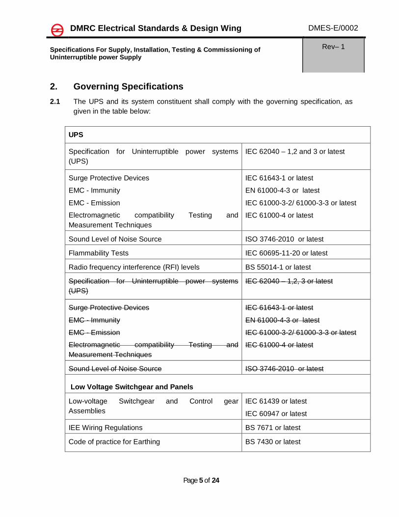
2. Governing Specifications 2.1 The UPS and its system constituent shall comply with the governing specification, as
given in the table below:
UPS
Specification for Uninterruptible power systems (UPS)
IEC 62040 – 1,2 and 3 or latest
Surge Protective Devices
EMC - Immunity
EMC - Emission
Electromagnetic compatibility Testing and Measurement Techniques
IEC 61643-1 or latest
EN 61000-4-3 or latest
IEC 61000-3-2/ 61000-3-3 or latest
IEC 61000-4 or latest
Sound Level of Noise Source ISO 3746-2010 or latest
Flammability Tests IEC 60695-11-20 or latest
Radio frequency interference (RFI) levels BS 55014-1 or latest
Specification for Uninterruptible power systems (UPS)
IEC 62040 – 1,2, 3 or latest
Surge Protective Devices
EMC - Immunity
EMC - Emission
Electromagnetic compatibility Testing and Measurement Techniques
IEC 61643-1 or latest
EN 61000-4-3 or latest
IEC 61000-3-2/ 61000-3-3 or latest
IEC 61000-4 or latest
Sound Level of Noise Source ISO 3746-2010 or latest Low Voltage Switchgear and Panels
Low-voltage Switchgear and Control gear Assemblies
IEC 61439 or latest
IEC 60947 or latest
IEE Wiring Regulations BS 7671 or latest
Code of practice for Earthing BS 7430 or latest

DMRC Electrical Standards & Design Wing DMES-E/0002
Specifications For Supply, Installation, Testing & Commissioning of Uninterruptible power Supply
Rev– 1
Page 6 of 24
3. Requirements 3.1 Functional Requirements 3.1.1 UPS 3.1.1.1 Features: The UPS shall be a true parallel redundant,(Clause 3.1.35 of IEC 62040-3 )
Double Conversion (Clause 3.2.16 of IEC 62040-3 )(VFI technology Online type.) and shall configure to A.3.2.2 of the IEC 62040-3 as Parallel Redundant with bypass. The UPS system shall consist of the components as defined under clause 3.1 of IEC 62040-3 and the basic configuration of each UPS shall be as shown below:-
The loads are generally linear to clause 3.2.6 of IEC 62040-3 but shall cater to non-linear loads to clause 3.2.7 of IEC 62040-3. UPS shall be compatible to take non-linear loads and capable to handle high crest load. The UPS shall be suitable for taking unbalanced load vide clause 3.5.22 of IEC 62040-3. UPS shall be provided with input power factor correction features.
3.1.1.2 Capacity: The capacity of the UPS shall be as per the BOQ. However, in general the ratings of UPS standardized for Delhi Metro applications are 20 kVA, 30 kVA, 60 kVA and 80 kVA.
GENERAL BLOCK DIAGRAM OF UPS SYSTEM

DMRC Electrical Standards & Design Wing DMES-E/0002
Specifications For Supply, Installation, Testing & Commissioning of Uninterruptible power Supply
Rev– 1
Page 7 of 24
3.1.1.3 Modes of Operation
The UPS shall operate in the following modes:-
3.1.1.3.1 Normal Mode (Mains Up) Clause No. 3.2.13 of IEC 62040-3
3.1.1.3.2 Stored Energy Mode (Mains Down) Clause 3.2.14 of IEC 62040-3 3.1.1.3.3 Battery Recharge (Mains Restored)
(a) When mains supply is restored from failure or restored via automatic supply changeover switch, the rectifier / charger shall resume the supply of DC power to the Inverter and batteries. During this period, no interruption or disturbance shall be caused to the inverter output.
(b) When the battery system is fully charged, the rectifier / charger shall automatically adjust the output voltage to float charge the battery system.
3.1.1.3.4 Automatic By-pass Mode (Static By-pass Switch) as defined vide clause 3.2.15 of IEC 62040-3 and also as following:
(a) In the event of overloads exceeding system capabilities (short-circuits, heavy inrush current or battery capacity being exhausted upon rectifier / charger supply down) or the detection of internal faults, the static by-pass switch shall instantaneously synchronize with the inverter output and transfer the loads to the bypass supply source without load interruption.
(b) Retransfer of the load to the UPS shall be accomplished, after the restoration and stabilization of the output power modules to the specified tolerances, without disturbance to the load.
In both these transfers, UPS output voltage and frequency tolerances must remain within the specified limits.
3.1.1.3.5 Built In / Manual By-pass Mode (Maintenance) as defined vide clause 3.2.15 of IEC 62040-3 and also as following:
The external independent manual bypass switch shall be manually operated to perform, make-before-break switching of the UPS load to either the UPS or the Mains supply source without load interruption, for UPS maintenance purposes. On UPS load being connected to by-pass supply, full access to the UPS input / output equipment shall be possible.
3.1.1.3.6 Maintenance of Batteries
For maintenance purposes, it shall be possible to isolate the battery system from the rectifier / charger and the Inverter by means of a circuit breaker. In such a case, the UPS shall continue to supply the load as specified herein, except in the event of mains supply outage.

DMRC Electrical Standards & Design Wing DMES-E/0002
Specifications For Supply, Installation, Testing & Commissioning of Uninterruptible power Supply
Rev– 1
Page 8 of 24
3.1.2 Sub components of UPS system
3.1.2.1 Automatic Supply Changeover System (For UG stations) Automatic Supply Changeover / Transfer System shall be provided in underground stations, with break-before-make switches. It shall switch the UPS to one of the two mains supply sources. When the selected mains supply source fails, the supply changeover unit shall automatically switch the rectifier / charger to the other mains supply source following a preset delay period
3.1.2.2 Rectifier/Charger The input of the rectifier / charger shall be protected by a circuit breaker with
adjustable settings. A walk-in circuit shall be provided at the rectifier / charger input to eliminate sudden inrush current from the mains supply or changeover of supply source. The current walk-in shall take place to allow a gradual increase in the loading in the mains supply source.
3.1.2.2.1 The UPS shall have IGBT rectifiers to remove harmonics. The converter should be solid state PWM converter with IGBT rectifiers. The converter should have the following important features.
a) Power Conversion
b) Battery Charging
c) Power Factor Improvement
d) Current Harmonic Reduction
e) Voltage Regulation
f) Transient Recovery
g) Automatic Synchronization
h) Over-current Protection
i) Over Temperature Protection
j) Control Power Failure Protection
k) Short Circuit Protection
l) Current limiting function of battery charging to prevent the battery from being damaged.
3.1.2.2.2 The rectifier / battery charger shall provide a regulated DC output for the inverter and the battery. The rectifier/charger regulation shall ensure that the DC output voltage fluctuations are less than 1% of rated value, irrespective of load and mains supply voltage variations.

DMRC Electrical Standards & Design Wing DMES-E/0002
Specifications For Supply, Installation, Testing & Commissioning of Uninterruptible power Supply
Rev– 1
Page 9 of 24
3.1.2.2.3 The rectifier / charger shall be equipped with a filter limiting the DC ripple voltage to a value less than 1% of the DC voltage.
3.1.2.2.4 The rectifier / charger shall have sufficient capacity to enable simultaneous supplying of full load to the inverter and recharging a fully discharged battery to 100% rated value within 10 hours.
3.1.2.2.5 A protective circuit shall be provided to prevent battery overcharge. After the rectifier / charger has recharged the battery to 100% capacity, the rectifier / charger shall float charge the battery.
3.1.2.2.6 Provision shall be made to prevent the battery from over-charging due to battery charger rectifier fault. An adjustable battery current limiting device shall limit the battery recharge current to the maximum value recommended by the battery manufacturer. The rectifier/charger shall be electronically current limited to protect the connections to the Inverter input and to prevent damage to the battery.
3.1.2.2.7 The battery low-volt cut-off shall be set to suit the battery manufacturer's recommendation to ensure the battery is not damaged by a deep discharge.
3.1.2.2.8 The rectifier/charger unit shall be equipped with an over-voltage protection device.
3.1.2.3 Inverter The inverter shall be a solid state device with proven Pulse Width Modulation technique utilizing Insulated Gate Bipolar Transistors and microprocessor controls, capable of accepting the output of the rectifier / charger or the battery system and provide a 3-phase alternating current output complying with the performance requirements.
3.1.2.3.1 The inverter shall utilize the latest and reliable technology to achieve high efficiency and reliability, and to cope with non-linear loads. The inverter should incorporate following essential features:
a) Voltage Regulation
b) Transient Recovery
c) Automatic Synchronization
d) Over-current Protection
e) Over Temperature Protection
f) Short Circuit Power Protection
g) High Speed switching
h) Frequency Control
i) Inverter Output voltage Harmonic distortion

DMRC Electrical Standards & Design Wing DMES-E/0002
Specifications For Supply, Installation, Testing & Commissioning of Uninterruptible power Supply
Rev– 1
Page 10 of 24
j) Inverter Overload protection through MCCB’s
k) Each inverter leg shall be protected from over-current to prevent damage to the solid-state devices in the inverter bridges.
3.1.2.3.2 The inverter output shall be electronically current limited.
3.1.2.3.3 The inverter shall be protected against over voltage and under voltage surges introduced at the output of the uninterruptible supply system by load switching and transfer to the bypass. If the bypass AC line deviates by more than 50 Hz ± 3%, the inverter logic shall automatically revert to 50 Hz ± 1 Hz and initiate an alarm condition The time taken to recover from transient to normal voltage shall not be more than 20 milliseconds.
3.1.2.4 Automatic Static Bypass Switch
3.1.2.4.1 The UPS shall be provided with a static by-pass switch(make before break type) which is synchronized with the UPS. In the case of inverter failure, sub-circuit failure, load start-up inrush or battery capacity being exhausted upon rectifier / charger supply down, the static bypass switch shall transfer the load to the mains automatically within 4 milli-seconds. The UPS shall withstand the switching transient or fault energy produced during operation of the static bypass switch parallels two different supply sources. Full protection discrimination shall be achieved on the bypass circuit. In case of a single sub-circuit fault, the capacity of the static by-pass switch shall withstand the fault energy until the protective device of the sub-circuit clear the fault. The continuous capacity of the Static bypass switch shall be equal to the 100% continuous rating of the inverter. The overload capacity shall be equivalent to the overload characteristics of the UPS. The current handling capacity of switch shall be 10 times for 20 milliseconds.
3.1.2.4.2 The means of operation shall ensure an uninterrupted transfer of load to or from the by-pass supply source under both automatic and manual mode of operation.
3.1.2.4.3 Transfer conditions
The static bypass switch shall transfer from the inverter to the by-pass supply source under the following conditions:
(1) Inverter under voltage (less than 90 % of nominal), (2) Inverter over voltage (greater than 110 % of nominal), (3) Inverter overload, (4) Inverter shut down for any reason (including failure) (5) Manual signal. (6) DC circuit under voltage or over voltage. (7) Final end voltage of the system battery is reached.

DMRC Electrical Standards & Design Wing DMES-E/0002
Specifications For Supply, Installation, Testing & Commissioning of Uninterruptible power Supply
Rev– 1
Page 11 of 24
At the same time, the inverter output shall be isolated to prevent the bypass supply source from back feeding power to the inverter.
3.1.2.4.4 Retransfer to Inverter The static by-pass switch shall be capable of automatically retransferring the load back to the Inverter after the Inverter has returned to normal voltage and stabilized for a period of time or the overload due to short-circuit or high inrush current has disappeared. The system shall only retransfer the load to the inverter provided all the following conditions are met:
(1) The inverter and the bypass supply source are synchronized. (2) Inverter voltage is within ± 5% of nominal for 2 to 30 seconds (adjustable). (3) Manual transfer signal off. (4) The overload current disappears within 1 to 10 minutes (adjustable).
3.1.2.5 External Independent Manual By-Pass Switch
A manually operated mechanical manual bypass switch shall be provided for the for maintenance on UPS and battery. The transfer scheme shall be make-before-break uninterrupted transfer of the load from the static bypass switch output to the external manual bypass supply source or vice versa. The switching arrangement shall be designed to electrically isolate the UPS from the distribution board. The current switching capacity of the manual bypass switch shall be at least four times the UPS rated output current. Key interlock between external manual bypass switch and the inverter switch shall be provided such that the inverter output cannot be changed over with the external manual bypass supply source directly. In addition, the manual bypass switch shall be pad-lockable.
3.1.2.6 Battery System For specifications and requirements, refer to the battery specifications DMES-E-
0003
3.2 Environmental conditions
All equipment shall be capable of withstanding any combination of the following external environmental conditions without any mechanical or electrical damage or degradation / deterioration in performance:
(1) Operating ambient temperature: 0oC to 40oC (2) Relative humidity: Up to 95 %
(3) Storage temperature 00 C to 500 C
(4) Operating altitude: As per IEC 62040-3.

DMRC Electrical Standards & Design Wing DMES-E/0002
Specifications For Supply, Installation, Testing & Commissioning of Uninterruptible power Supply
Rev– 1
Page 12 of 24
The equipment shall be designed to provide rated output at the extreme environmental conditions specified above.
3.3 Performance requirements 3.3.1. Input Parameters
(a) Input Voltage:- 415 V (AC) / 240 V (AC) (As per requirement). Each with input voltage tolerance of (–10% to + 10%).
(b) Wiring:- 3-phase, 4 wire and earth for Three Phase input/ Single phase and Neutral for Single Phase input.
(c) Input Frequency:- 50 Hz ± 5%
(d) Input Power Factor:- The total power factor of UPS as a load shall be from 0.99 lagging to unity, with rated load, fully charged battery, and input voltage within (–10% to + 10%) of the nominal value. (e) Harmonics on Input Voltage:- Input voltage distortion factor shall not exceed 0.08 and harmonic components shall not exceed values given in IEC 62040-3, Clause 5.2.1 d (f) Reflected Input Current Harmonics:- The rms value of all harmonics in the input current waveform contributed by UPS shall be less than 5%.
(g) Current Limiting:-The system shall be provided with inrush current limiting to 125% of the rated UPS load current
3.3.2 Output Parameters
(a) Rated voltage: 415 / 240V, 3 Phase 4 wire / single phase respectively.
(b) Steady state voltage regulation: ± 1% for a load between 0 and 100% of full rated value, irrespective of value of the normal mains supply voltage and DC voltage, provided these voltages are within the limits specified.
(c) Transient voltage regulation: Should be less than 3%.
(e) Output Voltage harmonic distortion: An output filter to be provided to limit total distortion to less than 5% with no single harmonic greater than 3%, irrespective of load and normal mains supply, provided these are within the limits specified.
(f) Steady state voltage unbalance (difference between phase voltage and the arithmetic average of the three phase voltage): ±1% maximum for balance load, ± 3% maximum for 50% unbalance load.
(g) Phase displacement: 120°±½° for balanced load; 120°±1° for 50% unbalanced load.

DMRC Electrical Standards & Design Wing DMES-E/0002
Specifications For Supply, Installation, Testing & Commissioning of Uninterruptible power Supply
Rev– 1
Page 13 of 24
(h) The output voltage shall not dip more than 20% in case of any fault on the load side of UPS.
(i) Output Frequency shall be as following:-
(1) Rated frequency: 50 Hz.
(2) In normal operation, the output frequency of the inverter shall be synchronized to that of the bypass supply source within the limits of 3% (settable)
(3) For frequency variations exceeding these limits, the inverter shall switch over to free-running mode, with regulation, providing an output frequency to within 1 Hz of the rated value without switching to batteries.
(4) Frequency slew rate: 2 Hz / second minimum maximum.
(j) Load Current Crest Factor: A crest factor up to 3:1 for the load current shall be anticipated.
(l) Load Unbalance Capacity:-The UPS shall have the capability to accept up to 50% load unbalance with the ratio of current in the most loaded phase to the current in the least loaded phase not exceeding 2, provided that the most loaded phase current does not exceed the rated line current.
(m) Overload Capability :-The UPS shall be able to supply 110% for 60 minutes, 125% rated load for at least 10 minutes and 150% rated load for at least 1 minute
(n) Output power factor:- 0.9 and above.
3.3.3 Noise Level Noise emanating from the UPS during operation shall not exceed
(a) 70 dBA for 80 kVA UPS
(b) 65 dBA for 60 kVA & 30 kVA UPS
(c) 55 dBA for 20 kVA and below UPS
at a distance of 1.5 m from the enclosure, over a load range of 10% to 100% of the rated full load and measured as per the standard.
It should be possible to change the internal parameters of the UPS(initially set by the manufacturer) in order to vary the output parameters, if required.
The UPS shall automatically analyze the condition of the battery string on a programmable period. It shall detect and enunciate the battery failure condition locally and remotely. The periodic test shall not impair the battery readiness in case of normal supply outage

DMRC Electrical Standards & Design Wing DMES-E/0002
Specifications For Supply, Installation, Testing & Commissioning of Uninterruptible power Supply
Rev– 1
Page 14 of 24
4. Additional Requirements 4.1 Diagnostics 4.1.1 The UPS shall be fitted with a Microprocessor based Supervision and Diagnostic
System, which monitors all aspects of the UPS operation. The system shall aid in the rapid identification of internal faults.
4.1.2 UPS shall be provided with RS 485 compatibility for remote monitoring and to extend alarm & status indications, annunciation and metering to BMS System located in Station Control Room. It shall be provided to communicate with an external computer for remote monitoring and diagnostics. The communication protocol shall be clearly documented and submitted for approval by the Engineer. Contractor must interface with the BMS Contractor regarding this
4.1.3 One portable terminal complete with all the necessary software and hardware accessories shall be provided at the Station for the monitoring and diagnostics of the UPS via the RS 485 data interface.
4.2 Display
4.2.1 All the modules and accessories shall be integral part of the main cubical and provide controls, metering & monitoring system and self-fault diagnostic / annunciation system for healthy/faulty status through LEDs, data logger with LCD display suitable display and power monitoring software for operational status locally. The UPS shall be fitted with an integral control and indication panel.
4.3 Instrumentation
The UPS shall be provided with, digital instrumentation to indicate, as a minimum, the following information. All readings shall have an accuracy of at least ± 0.5% of true value and the settling time shall be less than 1 second. If certain meter is used to display more than one parameter, a manual selector switch shall be provided for reading selection.
(a) True RMS voltage
(1) UPS input voltage with phase selection,
(2) Rectifier output voltage,
(3) DC battery voltage, and
(4) UPS output voltage with phase selection.
(b) True RMS current (crest factor – 3:1)
(1) UPS input current with phase selection,
(2) DC battery charge/discharge currents,
(3) UPS output current with phase selection, and

DMRC Electrical Standards & Design Wing DMES-E/0002
Specifications For Supply, Installation, Testing & Commissioning of Uninterruptible power Supply
Rev– 1
Page 15 of 24
(4) By-pass source current with phase selection.
(c) Frequency
(1) Mains frequency, and
(2) UPS output frequency.
(d) Power (kW)
(1) UPS output power with phase selection.
(e) Power Factor
(1) Inverter output power factor
(f) Elapsed operating time.
4.4 Indications and alarms
(a) The UPS shall include a mimic diagram with LED suitable display indication for the UPS equipment status and audible and visual alarm alerting annunciation. The status indication and alarm annunciation with the associated protection and control circuits shall include, but not be limited to, the following status and alarms.
Equipment Status Alarms UPS Input Voltage
UPS Output Voltage
Dual Supply, Healthy Status
Rectifier/Charger Rectifier Normal/Failure
Rectifier Failure
Boost / Float Charge
Battery Battery Charging / Discharging
Circuit Breaker Open
Battery Test Run
Battery Discharging
Battery Low Voltage
Battery Earth Fault
Battery Test Fail
DC Over voltage

DMRC Electrical Standards & Design Wing DMES-E/0002
Specifications For Supply, Installation, Testing & Commissioning of Uninterruptible power Supply
Rev– 1
Page 16 of 24
Inverter Inverter Normal/Failure
Inverter Failure
Inverter Overloaded
Output over voltage / under voltage.
Static By-pass By-pass Normal / Failure
Load on Inverter / Bypass
By-pass Failure
Synchronous Failure
Static switch on manual
Manual Bypass Load on UPS / Bypass
Manual Bypass Off / On
Transfer Inhibited
Ventilation Fan Normal / Failure, or
Over temperature alarm / shutdown (two stages)
Fan Failure, or
Over temperature alarm (adjustable)
Over temperature shutdown (adjustable)
Emergency Pushbutton UPS On/Emergency Shutdown
Emergency Shut Down with protective cover.
Common Alarm Alarm triggered - Common Alarm
Also, the following control should be present:
(h) Alarm test/reset push buttons
(ii) Lamp test/reset push buttons,
(iii) Alarm silence push button.
DMRC Electrical Standards & Design Wing DMES-E/0002
Specifications For Supply, Installation, Testing & Commissioning of Uninterruptible power Supply
Rev– 1
Page 17 of 24
(b) There should be an alarm upon the occurrence of any faults or failures as mentioned above, along with an indication at the remote BMS panel. Audible and visual annunciation shall be activated at the indication panel when an alarm has occurred. Such annunciation shall be latched on alarm occurrence and shall be such that it can only be cleared by pressing a manual reset button.
(c) The alarm state indications on mimic diagram shall remain until a manual reset switch is operated and the alarm state has been cleared.
(d) Remote monitoring status:- The following critical status and alarms of UPS shall report to Station Building Management System (BMS) controller for remote monitoring via volt-free contacts rated 24 V DC, 1A provided in the UPS modules:
(i) Supply A normal / failure
(ii) Supply B normal / failure
(iii) Load on inverter / bypass
(iv) Battery charging / discharging
(v) Manual bypass off / on
(vi) UPS (rectifier / charger / inverter / bypass switches) common alarm
(vii) Battery common alarm
(viii) Fan normal / failure or Over temperature alarm / shutdown
(ix) UPS on / emergency shutdown.
(e) Remote Control:- There will be no remote control for the UPS except Emergency shutdown push buttons in readily accessible locations, fitted with non-lockable covers or shrouds.
(f) There should be a system of communication provided with the UPS for transferring the Battery run test and inverter failure data to mobile telephone of OCC in the elevated stations and through BMS in underground stations.
5. Safety 5.1 UPS shall be designed for low impedance, less than 50V touch voltage and
limited ripple content. Two independent and distinct earth electrodes connections shall be provided for earthing of UPS connections comprising 50 x 4 mm Copper strips / 50 x 6 mm GI strips or as required / approved. Surge protective devices shall be provided at the inputs and output of the UPS to protect the UPS and the load equipment against any power surge due to lightning, switching, etc

DMRC Electrical Standards & Design Wing DMES-E/0002
Specifications For Supply, Installation, Testing & Commissioning of Uninterruptible power Supply
Rev– 1
Page 18 of 24
The UPS system shall be equipped with an interlocking system to prevent parallel operation of any non-synchronized sources activated either by any manual switches or automatic switches.
The UPS output shall be supplied via MCCB’s means of isolation with suitable protection, sufficient to supply the full rated output load.
The module shall be designed such that if there is a single fan failure or over temperature, an alarm shall sound, but it will in no way produce degradation of performance. In case of unavoidable shutdown due to excessive temperature rise, a warning alarm shall be given out at least 30 minutes before the shutdown.
All cabinets shall be solidly bonded to earth in accordance with BS 7430 using adequate section of cable or bus bar. The earth connection at the cabinets/enclosures shall be made to the frame earth provided or alternatively to a substantial part of the basic frame rather than a bolted - on panel.
5.2 Circuit Protection
MCCB’s Means of isolation with suitable protection shall be provided at both input and output within the UPS, which fully discriminate with upstream and downstream circuit breakers. The system shall be provided with component protection, to minimize damage and downtime in the event of component failure, against:
a) AC Supply voltage transients and transfers.
b) Internal faults.
c) Sustained overload.
d) Load switching transients.
e) Current surges.
The system shall be provided with interlocks to prevent accidental damage to the UPS during maintenance or normal operation.
5.3 UPS system shall be designed with protection & annunciation system for monitoring the following:
1. Phase sequence.
2. Overload and short circuit trip.
3. Earth fault.
4. Reverse Power Flow.
5. Low battery voltage.
6. Fault indication alarm through suitably designed hooter.

DMRC Electrical Standards & Design Wing DMES-E/0002
Specifications For Supply, Installation, Testing & Commissioning of Uninterruptible power Supply
Rev– 1
Page 19 of 24
7. Self-diagnostic annunciation system. 8. Ventilation Failure
9. Temperature monitoring
The manufacturer shall provide the scheme of operation of various protective devices for the above mentioned conditions.
5.4 Emissions in case of fire
The equipment shall produce low smoke and no toxic emissions in case of internal or external fire/over-heating.
The equipment shall not have any component which bursts with smoke or toxic emission. The AC and DC capacitors used shall have over pressure safety device or disconnector.
Cables, wires & insulating materials used, shall be fire retardant, low smoke and zero halogen material.
6. System efficiency The efficiency of the proposed UPS shall be at least 90% and above from 25% load to full load. The life and efficiency is of prime importance. The manufacture may offer UPS with any new proven technology having advantage of life and energy efficiency without compromising on other parameters of specification.
7. Reliability, maintenance, spares & life 7.1 The system shall have high operating efficiency, front access and self-diagnostic
features. There shall be sufficient redundancy in all vital parts to achieve a breakdown free operation of the system. The reliability shall be greater than 99.9%. The manufacturer shall provide data confirming to the required reliability.
7.2 The UPS shall be designed for maintenance free working. The conditioning monitoring system through sensing of all parameters of working equipments shall be designed to take care of incipient faults to undertake any unscheduled repairs without causing consequential damages.
7.3 Equipment shall be designed and manufactured in modular manner to facilitate the fault diagnosis and replacement of each modular part. Each module shall be capable of being interchanged with other modules of the same type without affecting the rest of modules in place
7.4 The service life of the UPS system shall be at least 20 years. The manufacturer shall submit the list of those items whose life does not match with the service life of UPS. The life of such spares shall be advised with a certificate from the

DMRC Electrical Standards & Design Wing DMES-E/0002
Specifications For Supply, Installation, Testing & Commissioning of Uninterruptible power Supply
Rev– 1
Page 20 of 24
manufacturer of the spares. The firm shall provide purchase specification of these items.
7.5 The manufacturer shall submit a list of all the spare parts with price list to be kept
after the expiry of defect liability period.
7.6 The vendor shall provide the Annual Maintenance cost of UPS system (including
batteries) for their full service life, in blocks of 5 years or year wise.
8. Material and manufacturing 8.1 Quality Assurance and Controls The Contractor’s Management Systems shall
emphasize quality assurance and controls. The programme shall be adequate to ensure an acceptable level of quality of the equipment supplied. The concept of total quality assurance shall be based on the principle that quality is a basic responsibility of the Contractor’s organization, and shall be visible by:
(a) Firm procurement and job performance specifications. (b) Firm procedures for transmission of information and data to their
Subcontractors and ensuring their compliance. (c) Adequate testing to ensure repetitive product conformity to design
requirements and Total programme of surveillance and verification of physical performance and configuration accountability.
(d) Adequate records shall be kept by the Contractor to provide evidence of quality and accountability. These records shall include results of inspections, tests, process controls, certification of processes and personnel, discrepant material, and other quality control requirements.
(e) Complaint handling and commitment towards customer satisfaction.
8.2 ISO certifications to which the quality standards are complied
8.3 Materials and Workmanship Requirements
All materials and processes to be used, whether incorporated in equipment at the manufacturer’s works or used for installation at site, shall comply with the requirements of this M&W Specification and shall conform to good modern practice. The following requirements shall be the minimum requirements and they shall not relieve the Supplier from ensuring that his designs are fit for purpose, and that all materials and processes are suited to their intended purposes and environments.
The basic workmanship and manufacturing principles shall be visible during visual inspection such as no sharp corners, sizing of screws/bolts, cable layout and

DMRC Electrical Standards & Design Wing DMES-E/0002
Specifications For Supply, Installation, Testing & Commissioning of Uninterruptible power Supply
Rev– 1
Page 21 of 24
identification, bedding and rubbing of parts, clearances, user friendly switches and indication panel etc.
All equipment and components supplied under the Contract shall have proven reliability and shall be designed, manufactured and installed to meet the specified and / or relevant international or national standards. The Contractor shall submit to the Engineer for approval, a list of all supplied equipment and components with a declaration of conformance to standards.
The manufacture shall supply information about the bill of material used in the manufacturing of the product if the Engineer so desire to satisfy himself about the use of quality material.
8.4 Mounting and Enclosure UPS shall be free standing and mounted as a whole on a heavy duty fabricated steel base frame constructed from folded channel sections with suitable mounting pads. All air entries shall be protected with cleanable filters. The cabinets shall be vermin and dust proof with IP 20 degree protection.
8.4.2 The Cabinet shall be constructed with material of thickness 1.6 mm for non-load bearing members and 2.5 mm for load bearing members and suitably braced to form a rigid structure. Full substantiation of mechanical strength shall be provided for approval to demonstrate that the cabinet is free from distortion when equipment is mounted and support on floor. All metallic cabinets shall have treatment for corrosion protection and painted with epoxy polyester paint.
8.4.3 The dimensions of the cabinets shall be optimally sized without requiring excessive floor space.
8.4.4 The equipment shall be constructed in modular units, which shall be installed in metal enclosures designed for floor mounting. Each module shall be constructed on a rigid base frame. Sub-assemblies and components shall be mounted on pull out and/or swing out trays. Cable connections to the cable ladder and trays shall be of sufficient length to allow for easy access to all components.
8.4.5 The UPS cabinet shall have a clear area of at least 900 mm in front to allow the doors to be opened fully and maintenance to take place. Doors shall be fitted with lockable handles or other approved means of fastening and shall be provided with locking bars and guides to prevent distortion. Cabinet shall be arranged so that access doors or panels into compartment can only be opened when the locking device is in the unlocked position. Two sets of keys shall be provided for each lock.
DMRC Electrical Standards & Design Wing DMES-E/0002
Specifications For Supply, Installation, Testing & Commissioning of Uninterruptible power Supply
Rev– 1
Page 22 of 24
8.4.6 Each Cabinet shall be fitted with metallic gland plates for entry of cables and an earth terminal. Foundation bolts and lifting hooks or eyes shall be provided as necessary for handling purposes.
8.4.7 It shall be fitted internally with a nameplate, which shall state the manufacturer’s name, address, telephone and e-mail address, serial number, rating and year of supply.
8.4.8 Danger warning notices with red letters on a white background shall be fitted to covers, which give access to live terminals or conductors at and above 110 volts. The danger board should be provided as per Indian Electricity Rules.
8.4.9 Circuit and function labels shall be provided. All labels shall be in one language as approved by Engineer. All switches or control unit provided for operation by Operating Staff shall be labeled with prominent display by letter size of minimum 6 mm.
8.4.10 The modules shall be designed to be transported in a horizontal and/or vertical mode as may be necessary to enable installation of the modules in the positions designated on Site.
8.4.11 Each of the items shall be adequately packed and protected against damage in transit from the manufacturer’s work area to the Site. Similarly, after delivery to Site, each cubicle shall be properly protected from damage until work is completed.
8.4.12 The mechanical and electrical design of all cabinets shall be submitted for approval by the Engineer.
8.4.13 Each cubicle shall be fitted with a designation label to show voltage rating and duty on the front and rear of the cubicle.
8.4.14 Each cubicle shall be equipped with internal luminaries operated via a door limit switch.
8.4.15 Each cubicle shall be provided a space for keeping operating manual along with other documents related to the UPS with suitable labeling.
8.5 Electronic Components and Sub-Assemblies 8.5.1 Each plug-in module or printed circuit board shall be securely plugged into the
main unit with guiding construct to hold the module in place. Printed edge connector shall not be used.
8.5.2 Printed circuit boards shall have sufficient thickness to ensure its mechanical rigidity and to eliminate the risk of damage during installation and maintenance. Dip switches shall be avoided as far as possible. Jumper wire is not allowed.

DMRC Electrical Standards & Design Wing DMES-E/0002
Specifications For Supply, Installation, Testing & Commissioning of Uninterruptible power Supply
Rev– 1
Page 23 of 24
8.5.3 Printed circuit boards shall be designed and manufactured to the accepted standards, which shall include standards for conductor thickness, width and spacing. Different standards shall be applied to equipment operated under different conditions if applicable.
8.5.4 All plug-in modules shall be clearly and unmistakably identified. Labeling with module name, part number, serial number and revision number shall be provided.
8.5.5 LED shall be provided with each plug-in module or printed circuit board to indicate the power supply and component fault status. They shall be easily visible without any obstructions.
8.5.6 The rated voltage of insulated terminal blocks shall be 415 V between terminals, 240 V to earth. Insulated terminal blocks shall comprise brass tubular connectors with screw connections contained within a moulded block suitable for working temperature up to 100°C.
8.5.7 Terminals shall be designed to clamp the conductor between metal surfaces with sufficient contact pressure but without causing damage to the conductor. With the largest recommended conductor in position, and tightly clamped, there shall be at least two full thread pitches of the screw engaging in the connector.
8.5.8 All materials and parts comprising the module system shall be new and of current manufacture of a high grade and free from all known defects and imperfections.
8.5.9 All active electronic devices shall be solid state. All semi-conductor devices shall be hermetically sealed. Vacuum tubes shall not be used for any purposes.
8.5.10 Terminals shall be supplied suitable for the cables being used to make the power connections. Terminals shall be provided for connecting the remote alarm contacts.
8.5.11 All power semi-conductors shall be fused in a manner to prevent cascaded or sequential semi-conductor failures. Indicator lamps denoting blown fuse conditions shall be located such as to be readily observable without removing panels or opening of the cabinet doors.
8.5.12 Isolating switches shall be of the load type with ON/OFF indication and lock attachment. Critical isolating switches essential for continuity of the load power shall be pad-lockable.
8.5.13 Contactors if any shall have Contactor coils suitable for use on direct current. Rectifiers shall be of the selenium type and terminals shall be provided to external control of the contactors on the AC side of the rectifier.
8.5.14 Relays shall be of the plug-in type and shall be housed in dust tight enclosures.

DMRC Electrical Standards & Design Wing DMES-E/0002
Specifications For Supply, Installation, Testing & Commissioning of Uninterruptible power Supply
Rev– 1
Page 24 of 24
8.6 Electrical Works and Accessories
All electrical equipment in the UPS, including MCCB, MCB, cable connector, trunking, conduit and other electrical accessories, shall comply with, the sections and clauses of the M & W Specifications, relevant to these items. All the cables and wires used must be of Low Smoke Zero halogen type.
9. Testing & Commissioning 9.1 The manufacturer of the UPS must have type test certificates, from an accredited/
reputed third party, for all the tests specified IEC 62040 – 3 and shall not be more than five years old.
9.2 In case, these are not available, manufacturer will be required shall arrange to get these tests executed from an accredited third party in their factory as per clause 6.6 of IEC 62040-3 in the presence of third party NABL certified body. The DMRC official may call for repeat of all or some of the tests during factory acceptance test.
9.3 Manufacturer will be required to carry out the routine and optional tests as specified in IEC 62040 – 3.
9.4 The UPS shall be thoroughly checked for correct operation and load tested in supplier works before dispatch. All faults created for check on satisfactory function of protection system, control functions, workmanship and site load conditions shall be simulated, checked and proved.
The equipment shall be dispatched after testing in presence of authorized representative of purchaser.
9.5 The manufacture representative shall be available at the time of commissioning and testing of UPS at site. The manufacture shall issue a certificate to the affect that the UPS has been installed and commissioned as per his approved scheme for the purpose.
10.0 Training: 10.1 The contractor shall ensure training of DMRC staff as decided by DMRC at DMRC
workplace or at his workplace as considered necessary. Training booklet along with audio-visual presentation shall be supplied to each trainee.
10.2 The contractor shall supply Handing over bound booklet consisting of the details of the UPS, operating manual, extracts of the warrant/DLP, details of service center, list of staff trained on the said design of the UPS, training material booklet or any other item considered necessary by the purchaser. The first page of the booklet shall be signed by the manufacture, contractor and DMRC Engineer.