DMM4020 Digital Multimeter Users Manual · Users Manual ii Environment ... 4-16. Measurement Units...
110
DMM4020 Digital Multimeter Users Manual 077-0364-00
Transcript of DMM4020 Digital Multimeter Users Manual · Users Manual ii Environment ... 4-16. Measurement Units...

DMM4020 Digital Multimeter
Users Manual
077-0364-00
Copyright © Tektronix. All rights reserved. Licensed software products are owned by Tektronix or its subsidiaries or suppliers, and are protected by national copyright laws and international treaty provisions. Tektronix products are covered by U.S. and foreign patents, issued and pending. Information in this publication supersedes that in all previously published material. Specifications and price change privileges reserved. TEKTRONIX and TEK are registered trademarks of Tektronix, Inc.
Contacting Tektronix, Inc.
Tektronix, Inc. 14200 SW Karl Braun Drive P.O. Box 500 Beaverton, OR 97077 USA For product information, sales, service, and technical support: - In North America, call 1-800-833-9200. - Worldwide, visit www.tektronix.com to find contacts in your area.
Warranty Tektronix warrants that the product will be free from defects in materials and workmanship for a period of three (3) years from the date of original purchase from an authorized Tektronix distributor. If the product proves defective during this warranty period, Tektronix, at its option, either will repair the defective product without charge for parts and labor, or will provide a replacement in exchange for the defective product. Batteries are excluded from this warranty. Parts, modules and replacement products used by Tektronix for warranty work may be new or reconditioned to like new performance. All replaced parts, modules and products become the property of Tektronix.
In order to obtain service under this warranty, Customer must notify Tektronix of the defect before the expiration of the warranty period and make suitable arrangements for the performance of service. Customer shall be responsible for packaging and shipping the defective product to the service center designated by Tektronix, shipping charges prepaid, and with a copy of customer proof of purchase. Tektronix shall pay for the return of the product to Customer if the shipment is to a location within the country in which the Tektronix service center is located. Customer shall be responsible for paying all shipping charges, duties, taxes, and any other charges for products returned to any other locations.
This warranty shall not apply to any defect, failure or damage caused by improper use or improper or inadequate maintenance and care. Tektronix shall not be obligated to furnish service under this warranty a) to repair damage resulting from attempts by personnel other than Tektronix representatives to install, repair or service the product; b) to repair damage resulting from improper use or connection to incompatible equipment; c) to repair any damage or malfunction caused by the use of non-Tektronix supplies; or d) to service a product that has been modified or integrated with other products when the effect of such modification or integration increases the time or difficulty of servicing the product.
THIS WARRANTY IS GIVEN BY TEKTRONIX WITH RESPECT TO THE PRODUCT IN LIEU OF ANY OTHER WARRANTIES, EXPRESS OR IMPLIED. TEKTRONIX AND ITS VENDORS DISCLAIM ANY IMPLIED WARRANTIES OF MERCHANTABILITY OR FITNESS FOR A PARTICULAR PURPOSE. TEKTRONIX' RESPONSIBILITY TO REPAIR OR REPLACE DEFECTIVE PRODUCTS IS THE SOLE AND EXCLUSIVE REMEDY PROVIDED TO THE CUSTOMER FOR BREACH OF THIS WARRANTY. TEKTRONIX AND ITS VENDORS WILL NOT BE LIABLE FOR ANY INDIRECT, SPECIAL, INCIDENTAL, OR CONSEQUENTIAL DAMAGES IRRESPECTIVE OF WHETHER TEKTRONIX OR THE VENDOR HAS ADVANCE NOTICE OF THE POSSIBILITY OF SUCH DAMAGES.
[W16 – 15AUG04]
.

i
Table of Contents
Chapter Title Page
1 Introduction and Specifications......................................................... 1-1 General Safety Summary ................................................................................... 1-3
To Avoid Fire or Personal Injury .............................................................. 1-3 Symbols and Terms................................................................................... 1-5 Safety and Electrical Symbols .................................................................. 1-5 Description of IEC 61010 Measurement Categories................................. 1-6
Compliance Information .................................................................................... 1-7 EMC Compliance .......................................................................................... 1-7
EC Declaration of Conformity—EMC ..................................................... 1-7 Australia / New Zealand Declaration of Conformity – EMC ................... 1-8
Safety Compliance......................................................................................... 1-8 EC Declaration of Conformity – Low Voltage ......................................... 1-8 U.S Nationally Recognized Testing Laboratory Listing ........................... 1-8 Canadian Certification .............................................................................. 1-8 Additional Compliances............................................................................ 1-8 Equipment Type ........................................................................................ 1-8 Safety Class............................................................................................... 1-8 Pollution Degree Description .................................................................... 1-8 Pollution Degree........................................................................................ 1-9 Measurement Overvoltage Categories ...................................................... 1-9
Environmental Considerations........................................................................... 1-9 Product End-of-Life Handling....................................................................... 1-9
Equipment Recycling ................................................................................ 1-9 Restriction of Hazardous Substances ........................................................ 1-9
Introduction........................................................................................................ 1-10 User Documentation .......................................................................................... 1-11 About this Manual ............................................................................................. 1-11 Instrument Security Procedures ......................................................................... 1-12
Volatile Memory ........................................................................................... 1-12 Non Volatile Memory.................................................................................... 1-12
Options and Accessories .................................................................................... 1-13 General Specifications ....................................................................................... 1-13
Voltage .......................................................................................................... 1-13 Dimensions .................................................................................................... 1-13 Display........................................................................................................... 1-14

DMM4020 Users Manual
ii
Environment .................................................................................................. 1-14 Triggering ...................................................................................................... 1-14 Math Functions.............................................................................................. 1-14 Electrical........................................................................................................ 1-14 Remote Interfaces .......................................................................................... 1-14 Warranty ........................................................................................................ 1-14
Electrical Specifications .................................................................................... 1-15 DC Voltage Specifications ............................................................................ 1-15 AC Voltage Specifications ............................................................................ 1-16 Resistance ...................................................................................................... 1-17 DC Current .................................................................................................... 1-17 AC Current .................................................................................................... 1-18 Frequency ...................................................................................................... 1-19 Continuity ...................................................................................................... 1-19 Diode Test ..................................................................................................... 1-19
2 Preparing the Meter for Operation..................................................... 2-1 Introduction........................................................................................................ 2-3 Unpacking and Inspecting the Meter ................................................................. 2-3 Storing and Shipping the Meter ......................................................................... 2-3 Power Considerations ........................................................................................ 2-3
Selecting the Line Voltage ............................................................................ 2-4 Replacing the Fuses....................................................................................... 2-4
Line-Power Fuse ....................................................................................... 2-4 Current-Input Fuses................................................................................... 2-5
Connecting to Line Power ................................................................................. 2-7 Turning Power On ............................................................................................. 2-7 Adjusting the Bail .............................................................................................. 2-8 Installing the Meter into an Equipment Rack .................................................... 2-9 Cleaning the Meter............................................................................................. 2-9 Fluke 45 Emulation Mode ................................................................................. 2-10 Illuminating All Display Segments.................................................................... 2-10
3 Operating the Meter from the Front Panel ........................................ 3-1 Introduction........................................................................................................ 3-2 Dual Display ...................................................................................................... 3-5
Primary Display............................................................................................. 3-5 Secondary Display......................................................................................... 3-5
Rear Panel .......................................................................................................... 3-7 Adjusting Meter Range ...................................................................................... 3-8 Selecting a Measurement Rate........................................................................... 3-8 Selecting a Measurement Function.................................................................... 3-8
Measuring Voltage ........................................................................................ 3-8 Measuring Frequency .................................................................................... 3-9 Frequency Ranging........................................................................................ 3-9 Measuring Resistance.................................................................................... 3-9
2-Wire Resistance Measurement............................................................... 3-10 4-Wire Resistance Measurement............................................................... 3-11
Measuring Current......................................................................................... 3-12 Automatic Input Terminal Detection............................................................. 3-13 Diode / Continuity Testing ............................................................................ 3-13 Making a Triggered Measurement ................................................................ 3-15
Setting the Trigger Mode .......................................................................... 3-15 Connecting to an External Trigger ............................................................ 3-15

Contents (continued)
iii
Selecting a Function Modifier ........................................................................... 3-17 Relative Readings Modifier (REL)................................................................ 3-17 Decibels and Auto Power Modifier ............................................................... 3-17 Touch Hold Function (HOLD) ...................................................................... 3-18 Minimum / Maximum Modifier (MIN MAX) .............................................. 3-19 Using the Function Modifiers in Combination.............................................. 3-20 Second Level Operations (Using the SHIFT Button).................................... 3-20
Compare Function (COMP)............................................................................... 3-21 Setting the Compare Range ........................................................................... 3-21 Using the Compare Function......................................................................... 3-21
List and Number Editors.................................................................................... 3-21 Using the List Editor ..................................................................................... 3-22 Using the Number Editor............................................................................... 3-22
Function Keys S1 – S6....................................................................................... 3-23 Power-Up Configuration.................................................................................... 3-24 Calibration ......................................................................................................... 3-24
4 Operating the Meter Using the Computer Interface ......................... 4-1 Introduction........................................................................................................ 4-4
Local and Remote Operations ....................................................................... 4-4 Computer Interfaces ...................................................................................... 4-4
Preparing the Meter for Operations via the RS-232 Interface ........................... 4-4 Setting Communication Parameters (RS-232) .............................................. 4-4 RS-232 Print-Only Mode .............................................................................. 4-5 Cabling the Meter to a Host or Printer (RS-232)........................................... 4-6 Character Echoing and Deletion.................................................................... 4-7 Device Clear Using ^C (CNTRL C).............................................................. 4-7 RS-232 Prompts............................................................................................. 4-7
Getting Started with an Installation Test ........................................................... 4-7 Installation Test for RS-232 Operation ......................................................... 4-7 If Test Fails.................................................................................................... 4-8
How the Meter Processes Input ......................................................................... 4-8 Input Strings .................................................................................................. 4-8 Input Terminators .......................................................................................... 4-8 Sending Numeric Values to the Meter .......................................................... 4-9 Sending Command Strings to the Meter........................................................ 4-9
How the Meter Processes Output....................................................................... 4-9 Triggering Output .............................................................................................. 4-10
External Triggering from the Front Panel ..................................................... 4-10 Setting the Trigger Type Configuration ........................................................ 4-11 External Trigger via the Computer Interface................................................. 4-11
Status Registers.................................................................................................. 4-12 Event Status and Event Status Enable Registers ........................................... 4-13 Status Byte Register ...................................................................................... 4-15 Reading the Status Byte Register .................................................................. 4-16
Computer Interface Command Set..................................................................... 4-16 Common Commands ..................................................................................... 4-17 Function Commands and Queries.................................................................. 4-18 Function Modifier Commands and Queries .................................................. 4-20 Range and Measurement Rate Commands and Queries................................ 4-22 Measurement Queries .................................................................................... 4-24 Compare Commands and Queries ................................................................. 4-25 Trigger Configuration Commands................................................................. 4-25 Miscellaneous Commands and Queries......................................................... 4-26
DMM4020 Users Manual
iv
RS-232 Remote / Local Configurations ........................................................ 4-27 RS-232 Save / Recall System Configurations ............................................... 4-27
Sample Program Using the RS-232 Computer Interface ................................... 4-27
Appendices A Applications ................................................................................................ A-1 B 2X4 Test Leads............................................................................................ B-1
Index

v
List of Tables
Table Title Page
1-1. Volatile Memory Space.......................................................................................... 1-13 1-2. Non-volatile Memory Space .................................................................................. 1-13 1-3. Accessories............................................................................................................. 1-14 2-1. Line Voltage to Fuse Rating................................................................................... 2-4 2-2. Line Power Cord Types Available from Tektronix................................................ 2-7 3-1. Front-Panel Features .............................................................................................. 3-4 3-2. Display Annunciators and Indicators ..................................................................... 3-7 3-3. Rear-Panel Features ............................................................................................... 3-8 3-4. RS-232 Pin Out ...................................................................................................... 3-17 3-5. RS232 Pin Out........................................................................................................ 3-19 3-6. Second Level Operations ....................................................................................... 3-21 3-7. List Editor Options................................................................................................. 3-23 3-8. Number Editor Options .......................................................................................... 3-24 3-9. Factory Power-Up Configuration........................................................................... 3-25 4-1. RS-232 Communication Parameters Factory Settings ........................................... 4-4 4-2. Print Rates in RS-232 Print-Only Mode ................................................................ 4-5 4-3. Trigger Types ......................................................................................................... 4-9 4-4. RS-232 Reading Transfer Rates ............................................................................. 4-10 4-5. Status Register Summary ....................................................................................... 4-11 4-6. Description of Bits in ESR and ESE ...................................................................... 4-14 4-7. Description of Bits in the Status Byte Register (STB)........................................... 4-14 4-8. Common Commands.............................................................................................. 4-16 4-9. Function Commands and Queries .......................................................................... 4-17 4-10. Function Modifier Commands and Queries ........................................................... 4-19 4-11. Range and Measurement Rate Commands and Queries ........................................ 4-21 4-12. Measurement Queries............................................................................................. 4-23 4-13. Compare Commands and Queries.......................................................................... 4-24 4-14. Trigger Configuration Commands ......................................................................... 4-24 4-15. Miscellaneous Commands and Queries ................................................................. 4-25 4-16. Measurement Units Output with Format 2............................................................. 4-25 4-17. Remote/Local Configuration Commands............................................................... 4-26 4-18. Save / Call System Configuration Commands ....................................................... 4-26

DMM4020 Users Manual
vi
vii
List of Figures
Figure Title Page
1-1. IEC 61010 Measurement Category (CAT) Levels................................................. 1-7 2-1. Replacing the Line Power Fuse.............................................................................. 2-5 2-2. Replacing the Current-Input Fuses......................................................................... 2-6 2-3. Bail Adjustment and Removal ............................................................................... 2-8 2-4. Boot Removal......................................................................................................... 2-9 3-1. Front Panel ............................................................................................................. 3-4 3-2. Display Annunciators and Indicators ..................................................................... 3-6 3-3. Rear Panel .............................................................................................................. 3-8 3-4. Voltage and Frequency Measurement.................................................................... 3-10 3-5. 2-Wire Resistance Measurement............................................................................ 3-11 3-6. 4-Wire Resistance Measurement............................................................................ 3-12 3-7. Input Connections for 4-Wire Ohms Using 2x4 Wire Leads ................................. 3-13 3-8. Current Measurement <200 mA............................................................................. 3-14 3-9. Current Measurement 200 mA to 10 A.................................................................. 3-14 3-10. Continuity Test....................................................................................................... 3-15 3-11. Diode Test .............................................................................................................. 3-15 3-12. External Trigger Circuit ......................................................................................... 3-17 4-1. External Trigger Using Pin 9 of RS-232 Interface................................................. 4-10 4-2. Overview of Status Data Structures ....................................................................... 4-12 4-3. Event Status and Event Status Enable Registers .................................................... 4-13 4-4. Sample Program for RS-232 Computer Interface .................................................. 4-27

DMM4020 Users Manual
viii
1-1
Chapter 1 Introduction and Specifications
Title Page
General Safety Summary ..................................................................................... 1-3 To Avoid Fire or Personal Injury ................................................................ 1-3 Symbols and Terms..................................................................................... 1-6 Safety and Electrical Symbols .................................................................... 1-6 Description of IEC 61010 Measurement Categories................................... 1-7
Compliance Information ...................................................................................... 1-8 EMC Compliance ............................................................................................ 1-8
EC Declaration of Conformity—EMC ....................................................... 1-8 Australia / New Zealand Declaration of Conformity – EMC ..................... 1-9
Safety Compliance........................................................................................... 1-9 EC Declaration of Conformity – Low Voltage ........................................... 1-9 U.S Nationally Recognized Testing Laboratory Listing ............................. 1-9 Canadian Certification ................................................................................ 1-9 Additional Compliances.............................................................................. 1-9 Equipment Type .......................................................................................... 1-9 Safety Class................................................................................................. 1-9 Pollution Degree Description ...................................................................... 1-9 Pollution Degree.......................................................................................... 1-10 Measurement Overvoltage Categories ........................................................ 1-10
Environmental Considerations............................................................................. 1-10 Product End-of-Life Handling......................................................................... 1-10
Equipment Recycling .................................................................................. 1-10 Restriction of Hazardous Substances .......................................................... 1-10 Introduction ................................................................................................. 1-11
User Documentation ............................................................................................ 1-12 About this Manual ............................................................................................... 1-12 Instrument Security Procedures ........................................................................... 1-13
Volatile Memory ............................................................................................. 1-13 Non Volatile Memory...................................................................................... 1-13
Options and Accessories ...................................................................................... 1-14 General Specifications ......................................................................................... 1-14
Voltage ............................................................................................................ 1-14 Dimensions ...................................................................................................... 1-14 Display............................................................................................................. 1-15 Environment .................................................................................................... 1-15 Triggering ........................................................................................................ 1-15
DMM4020 Users Manual
1-2
Math Functions................................................................................................ 1-15 Electrical.......................................................................................................... 1-15 Remote Interfaces ............................................................................................ 1-15 Warranty .......................................................................................................... 1-15
Electrical Specifications ...................................................................................... 1-16 DC Voltage Specifications .............................................................................. 1-16 AC Voltage Specifications .............................................................................. 1-17 Resistance ........................................................................................................ 1-18 DC Current ...................................................................................................... 1-18 AC Current ...................................................................................................... 1-19 Frequency ........................................................................................................ 1-20 Continuity ........................................................................................................ 1-20 Diode Test ....................................................................................................... 1-20
Introduction and Specifications General Safety Summary 1
1-3
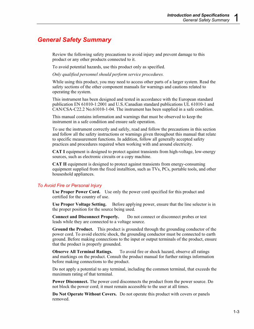
General Safety Summary Review the following safety precautions to avoid injury and prevent damage to this product or any other products connected to it. To avoid potential hazards, use this product only as specified. Only qualified personnel should perform service procedures. While using this product, you may need to access other parts of a larger system. Read the safety sections of the other component manuals for warnings and cautions related to operating the system. This instrument has been designed and tested in accordance with the European standard publication EN 61010-1:2001 and U.S./Canadian standard publications UL 61010-1 and CAN/CSA-C22.2 No.61010-1-04. The instrument has been supplied in a safe condition. This manual contains information and warnings that must be observed to keep the instrument in a safe condition and ensure safe operation. To use the instrument correctly and safely, read and follow the precautions in this section and follow all the safety instructions or warnings given throughout this manual that relate to specific measurement functions. In addition, follow all generally accepted safety practices and procedures required when working with and around electricity. CAT I equipment is designed to protect against transients from high-voltage, low-energy sources, such as electronic circuits or a copy machine. CAT II equipment is designed to protect against transients from energy-consuming equipment supplied from the fixed installtion, such as TVs, PCs, portable tools, and other houseshold appliances.
To Avoid Fire or Personal Injury Use Proper Power Cord. Use only the power cord specified for this product and certified for the country of use. Use Proper Voltage Setting. Before applying power, ensure that the line selector is in the proper position for the source being used. Connect and Disconnect Properly. Do not connect or disconnect probes or test leads while they are connected to a voltage source. Ground the Product. This product is grounded through the grounding conductor of the power cord. To avoid electric shock, the grounding conductor must be connected to earth ground. Before making connections to the input or output terminals of the product, ensure that the product is properly grounded. Observe All Terminal Ratings. To avoid fire or shock hazard, observe all ratings and markings on the product. Consult the product manual for further ratings information before making connections to the product. Do not apply a potential to any terminal, including the common terminal, that exceeds the maximum rating of that terminal. Power Disconnect. The power cord disconnects the product from the power source. Do not block the power cord; it must remain accessible to the user at all times. Do Not Operate Without Covers. Do not operate this product with covers or panels removed.
DMM4020 Users Manual
1-4
Do Not Operate With Suspected Failures. If you suspect that there is damage to this product, have it inspected by qualified service personnel. Avoid Exposed Circuitry. Do not touch exposed connections and components when power is present. Use Proper Fuse. Use only the fuse type and rating specified for this product. Keep Product Surfaces Clean and Dry.
XW Warning To avoid possible electric shock, personal injury, or death, read the following before using the Meter.
• Use the Meter only as specified in this manual, or the
protection provided by the Meter might be impaired. • Do not use the Meter in wet environments. • Inspect the Meter before using it. Do not use the Meter if it
appears damaged. • Inspect the test leads before use. Do not use them if
insulation is damaged or metal is exposed. Check the test leads for continuity. Replace damaged test leads before using the Meter.
• Verify the Meter's operation by measuring a known voltage before and after using it. Do not use the Meter if it operates abnormally. Protection may be impaired. If in doubt, have the Meter serviced.
• Whenever it is likely that safety protection has been impaired, make the Meter inoperative and secure it against any unintended operation.
• Servicing of the Meter should be performed by qualified service personnel.
• Do not apply more than the rated voltage, as marked on the Meter, between the terminals or between any terminal and earth ground.
• While in IEC Measurement Category II environments, do not apply voltages above 600 V ac to the input of the Meter. See “Description of IEC 61010 Measurement Categories” later in this manual.
• Always use the power cord and connector appropriate for the voltage and outlet of the country or location in which you are working.
• Always use a power cord with a ground connection and ensure the ground is properly connected to the power distribution system.
• Remove test leads from the Meter before opening the case. • Never remove the cover or open the case of the Meter
without first removing it from the main power source.
Introduction and Specifications General Safety Summary 1
1-5
• Use caution when working with voltages above 30 V ac rms, 42 V ac peak, or 42 V dc. These voltages pose a shock hazard.
• Use only the replacement fuse(s) specified by the manual. • Use the proper terminals, function, and range for your
measurements. • Do not operate the Meter around explosive gas, vapor, or
dust. • When using probes, keep your fingers behind the finger
guards. • When making electrical connections, connect the common
test lead before connecting the live test lead; when disconnecting, disconnect the live test lead before disconnecting the common test lead.
• Disconnect circuit power and discharge all high-voltage capacitors before testing resistance, continuity, diodes, or capacitance.
• Before measuring current, check the Meter's fuses and turn OFF power to the circuit before connecting the Meter to the circuit.
• When servicing the Meter, use only specified replacement parts.

DMM4020 Users Manual
1-6
Symbols and Terms The following terms and safety and electrical symbols may appear in the manual or on the product: A XW Warning statement identifies conditions or practices that could result in injury or death. A W Caution statement identifies conditions or practices that could result in damage to the Meter or equipment to which it is connected.
XW Warning To avoid electric shock, personal injury, or death, carefully read the information under “General Safety Summary” before attempting to install, use, or service the Meter.
Safety and Electrical Symbols
Symbol Description Symbol Description
W Risk of danger. Important information. See manual.
P Display ON / OFF and Meter reset.
X Hazardous voltage. Voltage > 30 V dc or ac peak might be present.
J Earth ground
B AC (Alternating Current) E Capacitance
F DC (Direct Current) G Diode
D or
C
AC or DC (Alternating or Direct Current)
I Fuse
R Continuity test or continuity beeper tone Y Digital signal
Y Potentially hazardous voltage U Maintenance or Service
T Double insulated h Static awareness. Static discharge can damage parts.
CAT II Measurement Category II is for measurements performed on circuits directly connected to the low voltage installation.
CAT I Measurement Category I is for measurements not directly connected to mains.
Introduction and Specifications General Safety Summary 1
1-7
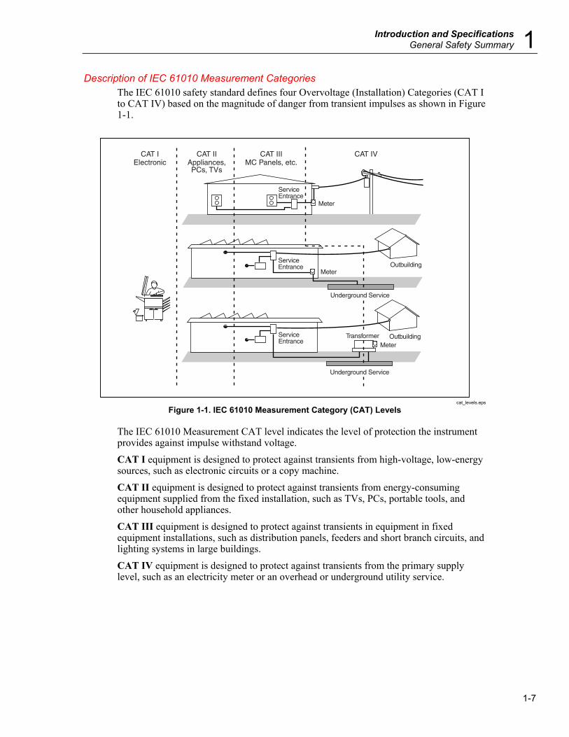
Description of IEC 61010 Measurement Categories The IEC 61010 safety standard defines four Overvoltage (Installation) Categories (CAT I to CAT IV) based on the magnitude of danger from transient impulses as shown in Figure 1-1.
ServiceEntrance
Meter
Meter
ServiceEntrance
Meter
Outbuilding
OutbuildingTransformer
Underground Service
Underground Service
CAT IElectronic
CAT IIAppliances,PCs, TVs
CAT IIIMC Panels, etc.
CAT IV
ServiceEntrance
cat_levels.eps
Figure 1-1. IEC 61010 Measurement Category (CAT) Levels
The IEC 61010 Measurement CAT level indicates the level of protection the instrument provides against impulse withstand voltage. CAT I equipment is designed to protect against transients from high-voltage, low-energy sources, such as electronic circuits or a copy machine. CAT II equipment is designed to protect against transients from energy-consuming equipment supplied from the fixed installation, such as TVs, PCs, portable tools, and other household appliances. CAT III equipment is designed to protect against transients in equipment in fixed equipment installations, such as distribution panels, feeders and short branch circuits, and lighting systems in large buildings. CAT IV equipment is designed to protect against transients from the primary supply level, such as an electricity meter or an overhead or underground utility service.

DMM4020 Users Manual
1-8
Compliance Information This section lists the EMC (electromagnetic compliance), safety, and environmental standards with which the instrument complies.
EMC ComplianceThe DMM4020 was evaluated using an M2 CDN with the instrument chassis referenced to earth ground.
EC Declaration of Conformity—EMC Meets intent of Directive 2004/108/EC for Electromagnetic Compatibility. Compliance was demonstrated to the following specifications as listed in the Official Journal of the European Communities:
EN 61326-1 2006, EN 61326-2 2006. EMC requirements for electrical equipment for measurement, control, and laboratory use. 1, 2, 3
CISPR 11:2003. Radiated and conducted emissions, Group 1, Class A IEC 61000-4-2:2001. Electrostatic discharge immunity IEC 61000-4-3:2002. RF electromagnetic field immunity IEC 61000-4-4:2004. Electrical fast transient/burst immunity IEC 61000-4-5:2001. Power line surge immunity IEC 61000-4-6:2003. Conducted RF immunity 4 IEC 61000-4-11:2004. Voltage dips and interruptions immunity 5
EN 61000-3-2:2006. AC power line harmonic emissions. EN 61000-3-3:1995. Voltage changes, fluctuations, and flicker. European Contact.
Tektronix UK, Ltd. Western Peninsula Western Road Bracknell, RG12 1RF United Kingdom
1 This product is intended for use in nonresidential areas only. Use in residential areas may cause electromagnetic interference. 2 Emissions which exceed the levels required by this standard may occur when this equipment is connected to a test object. 3 To ensure compliance with the EMC standards listed here, high quality shielded interface cables should be used. 4 The specified tolerances of the lower ranges of the VAC function while subjected to the injected test signal (3 V rms over the frequency range of 150 kHz to 80 MHz, with 80% amplitude modulation at 1 kHz) are dependent upon a known quiet protective earth reference connection. The DMM4020 was evaluated using an M2 CDN with the instrument chassis reference to earth ground. Significant measurement error can result under excessively noisy chassis reference conditions. (IEC 61000-4-6). 5 Performance Criterion C applied at the 0%/250 cycle Voltage-Interruption test levels (IEC 61000-4-11).

Introduction and Specifications Compliance Information 1
1-9
Australia / New Zealand Declaration of Conformity – EMC Complies with the EMC provision of the Radiocommunications Act per the following standard, in accordance with ACMA: CISPR 11:2003. Radiated and Conducted Emissions, Group 1, Class A, in accordance with EN 61326-1:2006 and EN 61326-2-1:2006.
Safety Compliance
EC Declaration of Conformity – Low Voltage Compliance was demonstrated to the following specification as listed in the Official Journal of the European Communities: Low Voltage Directive 2006/95/EC.
EN 61010-1: 2001. Safety requirements for electrical equipment for measurement control and laboratory use.
U.S Nationally Recognized Testing Laboratory Listing ISA-82.02.01. Safety Standard for Electrical and Electronic Test, Measuring,
Controlling and Related Equipment -- General Requirements.
Canadian Certification CAN/CSA-C22.2 No. 61010-1:2004. Safety requirements for electrical
equipment for measurement, control, and laboratory use. Part 1.
Additional Compliances IEC 61010-1: 2001. Safety requirements for electrical equipment for
measurement, control, and laboratory use. ANSI/UL 61010-1:2004, 2nd Edition. Standard for electrical measuring and
test equipment.
Equipment Type Test and measuring.
Safety Class Class 1 — grounded product.
Pollution Degree Description A measure of the contaminants that could occur in the environment around and within a product. Typically the internal environment inside a product is considered to be the same as the external. Products should be used only in the environment for which they are rated.
Pollution Degree 1. No pollution or only dry, nonconductive pollution occurs. Products in this category are generally encapsulated, hermetically sealed, or located in clean rooms.
Pollution Degree 2. Normally only dry, nonconductive pollution occurs. Occasionally a temporary conductivity that is caused by condensation must be expected. This location is a typical office/home environment. Temporary condensation occurs only when the product is out of service.

DMM4020 Users Manual
1-10
Pollution Degree 3. Conductive pollution, or dry, nonconductive pollution that becomes conductive due to condensation. These are sheltered locations where neither temperature nor humidity is controlled. The area is protected from direct sunshine, rain, or direct wind.
Pollution Degree 4. Pollution that generates persistent conductivity through conductive dust, rain, or snow. Typical outdoor locations.
Pollution Degree Pollution Degree 2 (as defined in IEC 61010-1). Note: Rated for indoor use only.
Measurement Overvoltage Categories CAT I – 1000V / CAT II – 600V
Environmental Considerations This section provides information about the environmental impact of the product.
Product End-of-Life Handling Observe the following guidelines when recycling an instrument or component:
Equipment Recycling Production of this equipment required the extraction and use of natural resources. The equipment may contain substances that could be harmful to the environment or human health if improperly handled at the product’s end of life. In order to avoid release of such substances into the environment and to reduce the use of natural resources, we encourage you to recycle this product in an appropriate system that will ensure that most of the materials are reused or recycled appropriately.
This symbol indicates that this product complies with the applicable European Union requirements according to Directives 2002/96/EC and 2006/66/EC on waste electrical and electronic equipment (WEEE) and batteries. For information about recycling options, check the Support/Service section of the Tektronix Web site (www.tektronix.com).
Restriction of Hazardous Substances This product has been classified as Monitoring and Control equipment, and is outside the scope of the 2002/95/EC RoHS Directive.
Introduction and Specifications Introduction 1
1-11
Introduction The Tektronix DMM4020 Digital Multimeter (hereafter referred to as the Meter) is a 5-1/2 digit dual-display multimeter designed for bench-top, field service, and system applications. The multiple measurement functions, plus the RS-232 remote interface, make the Meter an ideal candidate for precision manual measurements and use in automated systems. For portability, the Meter includes a carrying handle that also serves as a bail for bench-top operation. Some features provided by the Meter are: • A dual vacuum fluorescent display that allows two properties of an input signal to be
displayed at the same time (e.g., ac voltage in one display and frequency in the other) • 5-1/2 digit resolution • True-rms ac • 2, 4 wire resistance or patented 2x4 wire resistance measurement technique • 200 mV to 1000 Vdc range with 1 μV sensitivity • 200 mV to 750 Vac rms with 1 μV sensitivity • 200 Ω to 100 MΩ with 1 mΩ sensitivity • 200 μA to 10 Adc with 1 nA sensitivity • 20 mA to 10 Aac with 100 nA sensitivity • Frequency measurements from 20 Hz to 1 MHz • Continuity and diode test • Measurement rates of 2.5, 20 and 100 samples/second (slow, medium and fast,
respectively) • Front-panel setup key for single key access to saved setups • A compare mode to determine if a measurement is within defined limits • Remote operation via the RS-232 interface • Closed-case calibration (no internal calibration adjustments)

DMM4020 Users Manual
1-12
User Documentation The user documentation for this Meter includes the following:
Accessory Where to find Part number
Safety and Installation Manual
+ +
071-2694-xx
Technical Reference (Specifications and Performance Verification) +
077-0365-xx
Users Manual (This manual)
Available in the following languages: +
English French Italian German Spanish Japanese S. Chinese T. Chinese Korean Russian
077-0364-xx 077-0376-xx 077-0377-xx 077-0378-xx 077-0379-xx 077-0380-xx 077-0381-xx 077-0382-xx 077-0383-xx 077-0384-xx
About this Manual This manual contains all the information a new user will need to operate the Meter effectively. This manual is divided into the following chapters:
Chapter 1, “Introduction and Specifications,” provides information on how safely to use the Meter, and standard and optional accessories and specifications. Chapter 2, “Preparing the Meter for Operation,” provides information on setting the Meter’s line voltage, connecting it to a power source, and turning the Meter on. Chapter 3, “Operating the Meter from the Front Panel,” provides detailed information on using the Meter from the front panel. Chapter 4, “Applications,” provides detailed information on using the Meter to make electrical measurements. Chapter 5, “Operating the Meter using the Computer Interface,” describes how to set up, configure, and operate the Meter via the RS-232 computer interface on the Meter’s rear panel. Appendices
Introduction and Specifications Instrument Security Procedures 1
1-13
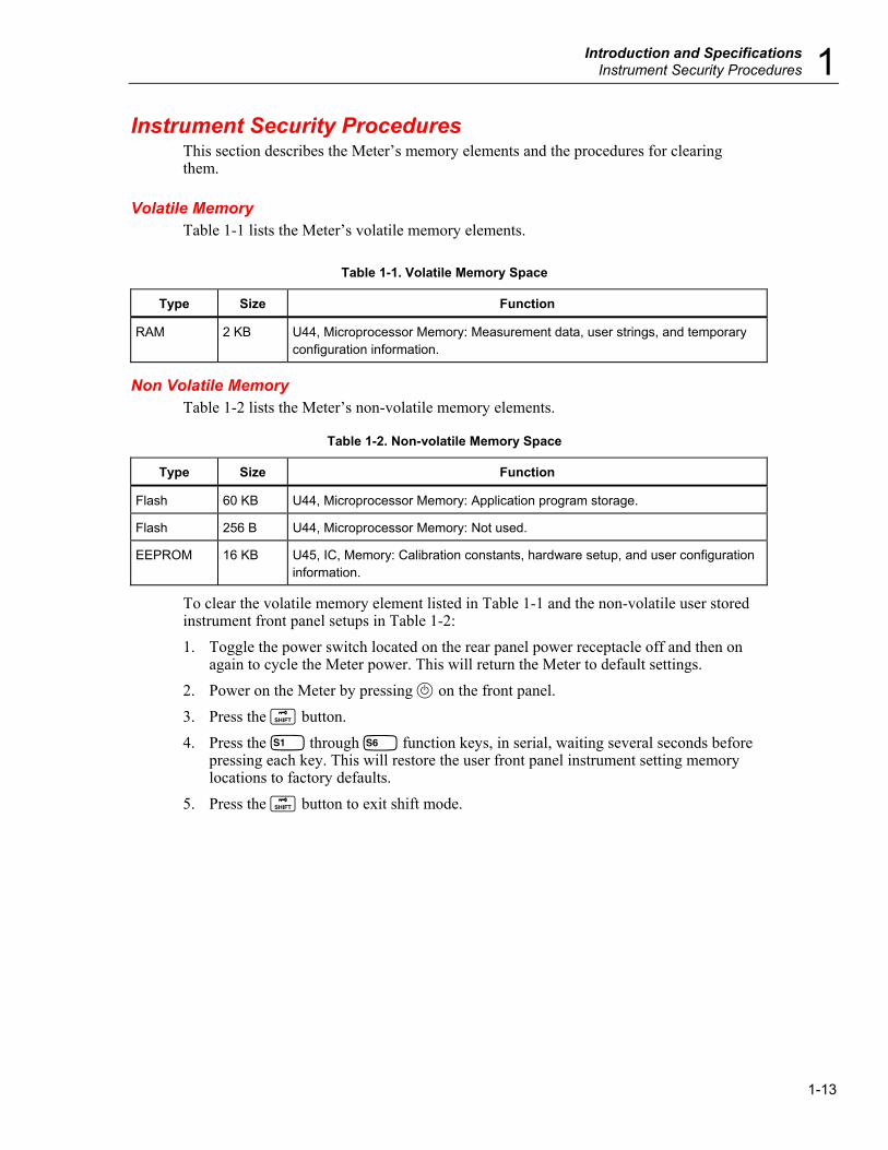
Instrument Security Procedures This section describes the Meter’s memory elements and the procedures for clearing them.
Volatile Memory Table 1-1 lists the Meter’s volatile memory elements.
Table 1-1. Volatile Memory Space
Type Size Function
RAM 2 KB U44, Microprocessor Memory: Measurement data, user strings, and temporary configuration information.
Non Volatile Memory Table 1-2 lists the Meter’s non-volatile memory elements.
Table 1-2. Non-volatile Memory Space
Type Size Function
Flash 60 KB U44, Microprocessor Memory: Application program storage.
Flash 256 B U44, Microprocessor Memory: Not used.
EEPROM 16 KB U45, IC, Memory: Calibration constants, hardware setup, and user configuration information.
To clear the volatile memory element listed in Table 1-1 and the non-volatile user stored instrument front panel setups in Table 1-2: 1. Toggle the power switch located on the rear panel power receptacle off and then on
again to cycle the Meter power. This will return the Meter to default settings. 2. Power on the Meter by pressing P on the front panel. 3. Press the Q button. 4. Press the a through f function keys, in serial, waiting several seconds before
pressing each key. This will restore the user front panel instrument setting memory locations to factory defaults.
5. Press the Q button to exit shift mode.
DMM4020 Users Manual
1-14
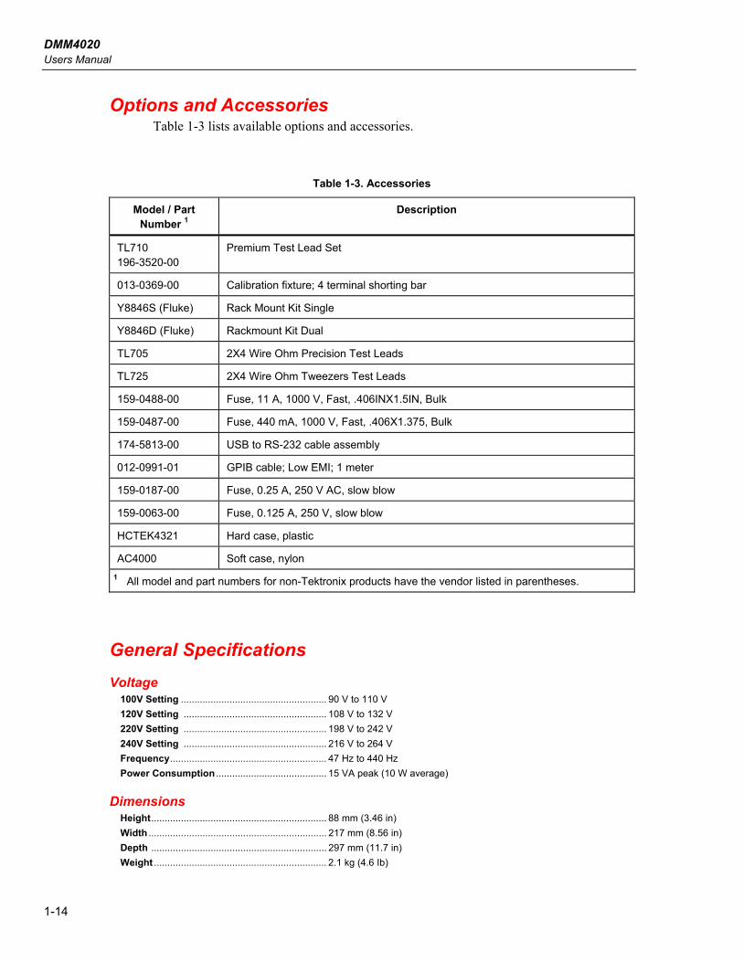
Options and Accessories Table 1-3 lists available options and accessories.
Table 1-3. Accessories
Model / Part Number 1
Description
TL710 196-3520-00
Premium Test Lead Set
013-0369-00 Calibration fixture; 4 terminal shorting bar
Y8846S (Fluke) Rack Mount Kit Single
Y8846D (Fluke) Rackmount Kit Dual
TL705 2X4 Wire Ohm Precision Test Leads
TL725 2X4 Wire Ohm Tweezers Test Leads
159-0488-00 Fuse, 11 A, 1000 V, Fast, .406INX1.5IN, Bulk
159-0487-00 Fuse, 440 mA, 1000 V, Fast, .406X1.375, Bulk
174-5813-00 USB to RS-232 cable assembly
012-0991-01 GPIB cable; Low EMI; 1 meter
159-0187-00 Fuse, 0.25 A, 250 V AC, slow blow
159-0063-00 Fuse, 0.125 A, 250 V, slow blow
HCTEK4321 Hard case, plastic
AC4000 Soft case, nylon 1 All model and part numbers for non-Tektronix products have the vendor listed in parentheses.
General Specifications Voltage
100V Setting ...................................................... 90 V to 110 V 120V Setting ..................................................... 108 V to 132 V 220V Setting ..................................................... 198 V to 242 V 240V Setting ..................................................... 216 V to 264 V Frequency.......................................................... 47 Hz to 440 Hz Power Consumption ......................................... 15 VA peak (10 W average)
Dimensions Height................................................................. 88 mm (3.46 in) Width .................................................................. 217 mm (8.56 in) Depth ................................................................. 297 mm (11.7 in) Weight ................................................................ 2.1 kg (4.6 Ib)

Introduction and Specifications General Specifications 1
1-15
Display Vacuum Fluorescent Display, segment
Environment Temperature
Operating ........................................................ 0 °C to 50 °C Storage ........................................................... -40 °C to 70 °C Warm Up......................................................... ½ hour to full uncertainty specifications
Relative Humidity (non-condensing) Operating ........................................................ <90 % (0 °C to 28 °C)
<75 % (28 °C to 40 °C) <45 % (40 °C to 50 °C)
Storage .......................................................... -40 °C to 70 °C <95 % Altitude
Operating ....................................................... 2,000 Meters Storage............................................................... 12,000 Meters Vibration ............................................................ Complies with MIL-PRF-28800F Class 3
Triggering Trigger Delay .................................................... 400 ms External Trigger Delay ..................................... <2 ms External Trigger Jitter ..................................... <1 ms Trigger Input ..................................................... TTL Levels Trigger Output ................................................... 5 V max
Math Functions Min/max, relative, hold, compare and dB functions
Electrical Input Protection ............................................... 1000 V all ranges Overrange .......................................................... 10 % on the largest ranges of all functions except continuity and diode
test
Remote Interfaces RS-232C
Warranty Three years

DMM4020 Users Manual
1-16
Electrical Specifications Specifications are valid for 5-½ digit mode and after at least a half-hour warm-up.
DC Voltage Specifications Maximum Input ................................................. 1000 V on any range Common Mode Rejection................................. 120 dB at 50 or 60 Hz ±0.1% (1 kΩ unbalance) Normal Mode Rejection .................................... 80 dB at Slow Rate A/D Nonlinearity ................................................ 15 ppm of range Input Bias Current ............................................ <30 pA at 25 °C Settling Considerations ................................... Measurement settling times are affected by source impedance, cable
dielectric characteristics, and input signal changes
Input Characteristics Resolution
Range Full-Scale (5-1/2 Digits) Slow Medium Fast
Input Impedance
200 mV 199.999 mV 1 μV 10 μV 10 μV >10 GΩ[1] 2 V 1.99999 V 10 μV 100 μV 100 μV >10 GΩ[1] 20 V 19.9999 V 100 μV 1000 μV 1000 μV 10 MΩ±1 %
200 V 199.999 V 1 mV 10 mV 10 mV 10 MΩ±1 %
1000 V 1000.00 V 10 mV 100 mV 100 mV 10 MΩ±1 % Notes:
[1] At some dual display measurements, the input impedance of 200 mV and 2 V ranges may be changed to 10 MΩ.
Accuracy Uncertainty [1]
90 days 1 year Range
23 °C ± 5 °C 23 °C ± 5°C
Temperature Coefficient/°C Outside 18 – 28 °C
200 mV 0.01 + 0.003 0.015 + 0.004 0.0015 + 0.0005 2 V 0.01 + 0.002 0.015 + 0.003 0.001 + 0.0005 20 V 0.01 + 0.003 0.015 + 0.004 0.0020 + 0.0005
200 V 0.01 + 0.002 0.015 + 0.003 0.0015 + 0.0005
1000 V 0.01 + 0.002 0.015 + 0.003 0.0015 + 0.0005
Notes:
[1] Uncertainty given as ± (% of reading + % of range)

Introduction and Specifications Electrical Specifications 1
1-17
AC Voltage Specifications AC Voltage specifications are for ac sinewave signals >5 % of range. For inputs from 1 % to 5 % of range and <50 kHz, add an additional error of 0.1 % of range, and for 50 kHz to 100 kHz, add 0.13 % of range.
Maximum Input ................................................. 750 V rms or 1000 V peak or 8 x 10⁷ Volts-Hertz product Measurement Method ....................................... AC-coupled true-rms. Measures the ac component of input with up to
1000 V dc bias on any range. AC Filter Bandwidth ......................................... 20 Hz – 100 kHz Common Mode Rejection................................. 60 dB at 50 Hz or 60 Hz (1 kΩ unbalance) Maximum Crest Factor .................................... 3:1 at Full Scale Additional Crest Factor Errors (<100 Hz) ...... Crest Factor 1-2, 0.05 % of full scale
Crest Factor 2-3, 0.2 % of full scale Only applies for non-sinusoid signals
Input Characteristics
Resolution Range Full-Scale
(5-1/2 Digits) Slow Medium Fast
Input Impedance
200 mV 199.999 mV 1 μV 10 μV 10 μV 2 V 1.99999 V 10 μV 100 μV 100 μV 20 V 19.9999 V 100 μV 1000 μV 1000 μV 200 V 199.999 V 1 mV 10 mV 10 mV 750 V 750.00 V 10 mV 100 mV 100 mV
1 MΩ ±2 % shunted by <100 pf
Accuracy Uncertainty [1]
90 days 1 year Range Frequency 23 °C ± 5 °C 23 °C ± 5 °C
Temperature Coefficient/°C
Outside 18 – 28 °C
200 mV 20 Hz – 45 Hz 0.8 + 0.05 0.9 + 0.05 0.01 + 0.005 45 Hz – 20 kHz 0.15 + 0.05 0.2 + 0.05 0.01 + 0.005 20 kHz – 50 kHz 0.3 + 0.05 0.35 + 0.05 0.01 + 0.005 50 kHz – 100 kHz 0.8 + 0.05 0.9 + 0.05 0.05 + 0.01 2 V 20 Hz – 45 Hz 0.8 + 0.05 0.9 + 0.05 0.01 + 0.005 45 Hz – 20 kHz 0.15 + 0.05 0.2 + 0.05 0.01 + 0.005 20 kHz – 50 kHz 0.3 + 0.05 0.35 + 0.05 0.01 + 0.005 50 kHz – 100 kHz 0.8 + 0.05 0.9 + 0.05 0.05 + 0.01 20 V 20 Hz – 45 Hz 0.8 + 0.05 0.9 + 0.05 0.01 + 0.005 45 Hz – 20 kHz 0.15 + 0.05 0.2 + 0.05 0.01 + 0.005 20 kHz – 50 kHz 0.3 + 0.05 0.35 + 0.05 0.01 + 0.005 50 kHz – 100 kHz 0.8 + 0.05 0.9 + 0.05 0.05 + 0.01 200 V 20 Hz – 45 Hz 0.8 + 0.05 0.9 + 0.05 0.01 + 0.005 45 Hz – 20 kHz 0.15 + 0.05 0.2 + 0.05 0.01 + 0.005 20 kHz – 50 kHz 0.3 + 0.05 0.35 + 0.05 0.01 + 0.005 50 kHz – 100 kHz 0.8 + 0.05 0.9 + 0.05 0.05 + 0.01 750 V 20 Hz – 45 Hz 0.8 + 0.05 0.9 + 0.05 0.01 + 0.005 45 Hz – 20 kHz 0.15 + 0.05 0.2 + 0.05 0.01 + 0.005 20 kHz – 50 kHz 0.3 + 0.05 0.35 + 0.05 0.01 + 0.005 50 kHz – 100 kHz 0.8 + 0.05 0.9 + 0.05 0.05 + 0.01
Notes:
[1] Uncertainty given as ± (% of reading + % of range)
DMM4020 Users Manual
1-18
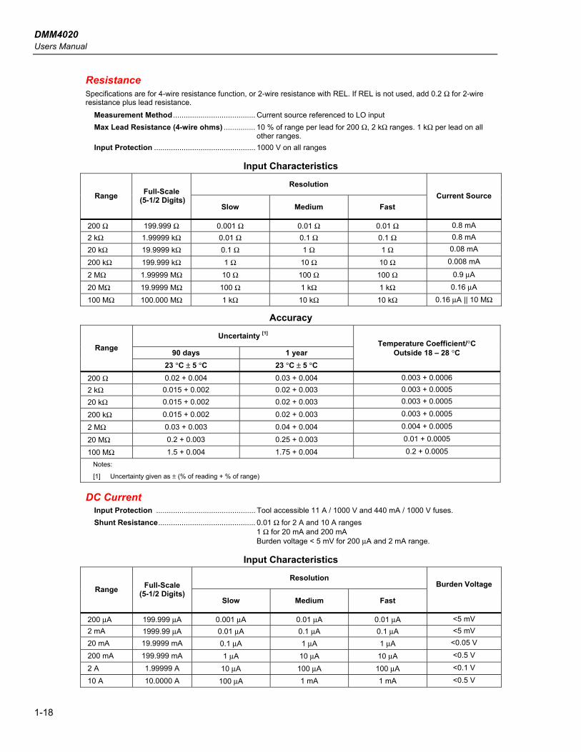
Resistance Specifications are for 4-wire resistance function, or 2-wire resistance with REL. If REL is not used, add 0.2 Ω for 2-wire resistance plus lead resistance.
Measurement Method ....................................... Current source referenced to LO input Max Lead Resistance (4-wire ohms) ............... 10 % of range per lead for 200 Ω, 2 kΩ ranges. 1 kΩ per lead on all
other ranges. Input Protection ................................................ 1000 V on all ranges
Input Characteristics
Resolution Range Full-Scale
(5-1/2 Digits) Slow Medium Fast
Current Source
200 Ω 199.999 Ω 0.001 Ω 0.01 Ω 0.01 Ω 0.8 mA 2 kΩ 1.99999 kΩ 0.01 Ω 0.1 Ω 0.1 Ω 0.8 mA
20 kΩ 19.9999 kΩ 0.1 Ω 1 Ω 1 Ω 0.08 mA
200 kΩ 199.999 kΩ 1 Ω 10 Ω 10 Ω 0.008 mA
2 MΩ 1.99999 MΩ 10 Ω 100 Ω 100 Ω 0.9 μA
20 MΩ 19.9999 MΩ 100 Ω 1 kΩ 1 kΩ 0.16 μA
100 MΩ 100.000 MΩ 1 kΩ 10 kΩ 10 kΩ 0.16 μA || 10 MΩ
Accuracy
Uncertainty [1]
90 days 1 year Range
23 °C ± 5 °C 23 °C ± 5 °C
Temperature Coefficient/°C Outside 18 – 28 °C
200 Ω 0.02 + 0.004 0.03 + 0.004 0.003 + 0.0006 2 kΩ 0.015 + 0.002 0.02 + 0.003 0.003 + 0.0005
20 kΩ 0.015 + 0.002 0.02 + 0.003 0.003 + 0.0005
200 kΩ 0.015 + 0.002 0.02 + 0.003 0.003 + 0.0005
2 MΩ 0.03 + 0.003 0.04 + 0.004 0.004 + 0.0005
20 MΩ 0.2 + 0.003 0.25 + 0.003 0.01 + 0.0005
100 MΩ 1.5 + 0.004 1.75 + 0.004 0.2 + 0.0005
Notes:
[1] Uncertainty given as ± (% of reading + % of range)
DC Current Input Protection ............................................... Tool accessible 11 A / 1000 V and 440 mA / 1000 V fuses. Shunt Resistance.............................................. 0.01 Ω for 2 A and 10 A ranges
1 Ω for 20 mA and 200 mA Burden voltage < 5 mV for 200 μA and 2 mA range.
Input Characteristics
Resolution Range Full-Scale
(5-1/2 Digits) Slow Medium Fast
Burden Voltage
200 μA 199.999 μA 0.001 μA 0.01 μA 0.01 μA <5 mV 2 mA 1999.99 μA 0.01 μA 0.1 μA 0.1 μA <5 mV 20 mA 19.9999 mA 0.1 μA 1 μA 1 μA <0.05 V
200 mA 199.999 mA 1 μA 10 μA 10 μA <0.5 V
2 A 1.99999 A 10 μA 100 μA 100 μA <0.1 V
10 A 10.0000 A 100 μA 1 mA 1 mA <0.5 V

Introduction and Specifications Electrical Specifications 1
1-19
Accuracy
Uncertainty [1]
90 days 1 year Range
23 °C ± 5 °C 23 °C ± 5 °C
Temperature Coefficient/°C Outside 18 – 28 °C
200 μA 0.02 + 0.005 0.03 + 0.005 0.003 + 0.001 2 mA 0.015 + 0.005 0.02 + 0.005 0.002 + 0.001 20 mA 0.03 + 0.02 0.04 + 0.02 0.005 + 0.001 200 mA 0.02 + 0.005 0.03 + 0.008 0.005 + 0.001 2 A 0.05 + 0.02 0.08 + 0.02 0.008 + 0.001 10 A 0.18 + 0.01 0.2 + 0.01 0.008 + 0.001
Notes:
[1] Uncertainty given as ± (% of reading + % of range)
AC Current The following ac current specifications are for sinusoidal signals with amplitudes greater than 5 % of range. For inputs from 1 % to 5 % of range, add an additional error of 0.1 % of range.
Input Protection ................................................ Tool accessible 11 A / 1000 V and 440 mA / 1000 V fuses Measurement Method ....................................... AC-coupled True RMS Shunt Resistance.............................................. 0.01 Ω for 2 A and 10 A ranges
1 Ω for 20 mA and 200 mA AC Filter Bandwidth ......................................... 20 Hz – 100 kHz Maximum Crest Factor ..................................... 3:1 at Full Scale Additional Crest Factor Errors (<100 Hz) ...... Crest Factor 1-2, 0.05 % of full scale
Crest Factor 2-3, 0.2 % of full scale Only applies to non-sinusoid signals
Input Characteristics Resolution
Range Full-Scale (5-1/2 Digits) Slow Medium Fast
Burden Voltage
20 mA 19.9999 mA 0.1 μA 1 μA 1 μA <0.05 V
200 mA 199.999 mA 1 μA 10 μA 10 μA <0.5 V
2 A 1.99999 A 10 μA 100 μA 100 μA <0.1 V
10 A 10.0000 A 100 μA 1 mA 1 mA <0.5 V
Accuracy Uncertainty [1]
90 days 1 year Range Frequency 23 °C ± 5 °C 23 °C ± 5 °C
Temperature Coefficient/°C
Outside 18 – 28 °C
20 mA 20 Hz – 45 Hz 1 + 0.05 1.25 + 0.06 0.015 + 0.005 45 Hz - 2 kHz 0.25 + 0.05 0.3 + 0.06 0.015 + 0.005 200 mA 20 Hz – 45 Hz 0.8 + 0.05 1 + 0. 06 0.015 + 0.005 45 Hz - 2 kHz 0.25 + 0.05 0.3 + 0.06 0.015 + 0.005 2 A 20 Hz – 45 Hz 1 + 0.05 1.25 + 0.06 0.015 + 0.005 45 Hz - 2 kHz 0.25 + 0.05 0.3 + 0.06 0.015 + 0.005 10 A 20 Hz – 45 Hz 1 + 0.1 1.25 + 0.12 0.015 + 0.005 45 Hz - 2 kHz 0.35 + 0.1 0.5 + 0.12 0.015 + 0.005
Notes:
[1] Uncertainty given as ± (% of reading + % of range)
DMM4020 Users Manual
1-20
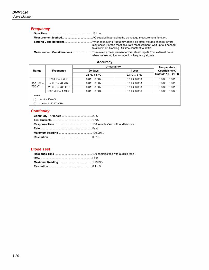
Frequency Gate Time .......................................................... 131 ms Measurement Method ....................................... AC-coupled input using the ac voltage measurement function. Settling Considerations ................................... When measuring frequency after a dc offset voltage change, errors
may occur. For the most accurate measurement, wait up to 1 second to allow input blocking RC time constant to settle.
Measurement Considerations ......................... To minimize measurement errors, shield inputs from external noise when measuring low voltage, low frequency signals.
Accuracy Uncertainty
90 days 1 year Range Frequency 23 °C ± 5 °C 23 °C ± 5 °C
Temperature Coefficient/°C
Outside 18 – 28 °C
20 Hz – 2 kHz 0.01 + 0.002 0.01 + 0.003 0.002 + 0.001 2 kHz – 20 kHz 0.01 + 0.002 0.01 + 0.003 0.002 + 0.001
20 kHz – 200 kHz 0.01 + 0.002 0.01 + 0.003 0.002 + 0.001 100 mV to 750 V[1,2]
200 kHz – 1 MHz 0.01 + 0.004 0.01 + 0.006 0.002 + 0.002 Notes:
[1] Input > 100 mV
[2] Limited to 8* 107 V Hz
Continuity Continuity Threshold........................................ 20 Ω Test Currents .................................................... 1 mA Response Time ................................................ 100 samples/sec with audible tone Rate .................................................................... Fast Maximum Reading ............................................ 199.99 Ω Resolution ......................................................... 0.01 Ω
Diode Test Response Time ................................................. 100 samples/sec with audible tone Rate .................................................................... Fast Maximum Reading ............................................ 1.9999 V Resolution ......................................................... 0.1 mV
2-1
Chapter 2 Preparing the Meter for Operation
Title Page
Introduction.......................................................................................................... 2-3 Unpacking and Inspecting the Meter ................................................................... 2-3 Storing and Shipping the Meter ........................................................................... 2-3 Power Considerations .......................................................................................... 2-3
Selecting the Line Voltage .............................................................................. 2-4 Replacing the Fuses......................................................................................... 2-4
Line-Power Fuse ......................................................................................... 2-4 Current-Input Fuses..................................................................................... 2-5
Connecting to Line Power ................................................................................... 2-7 Turning Power On ............................................................................................... 2-7 Adjusting the Bail ................................................................................................ 2-8 Installing the Meter into an Equipment Rack ...................................................... 2-9 Cleaning the Meter............................................................................................... 2-9 Fluke 45 Emulation Mode ................................................................................... 2-10 Illuminating All Display Segments...................................................................... 2-10

DMM4020 Users Manual
2-2

Preparing the Meter for Operation Introduction 2
2-3
Introduction This chapter explains how to prepare the Meter for operation by selecting the proper line voltage, connecting the proper power cord for the selected line voltage, and turning the Meter on. Also included is information on the proper storage, shipping, and cleaning of the Meter.
Unpacking and Inspecting the Meter Every care is taken in the choice of packing material to ensure that your Meter will reach you in perfect condition. If the Meter has been subject to excessive handling in transit, there may be visible external damage to the shipping carton. In the event of damage, keep the shipping container and packing material for the carrier’s inspection. Carefully unpack the Meter from its shipping container and inspect the contents for damaged or missing items. If the Meter appears damaged or something is missing, contact the carrier and Tektronix immediately. Save the container and packing material in case you have to return the Meter.
Storing and Shipping the Meter To prepare the Meter for storage or shipping, place it inside a sealed bag, fit the bag into the packing material inside the original shipping container, and then secure the package. Use the original shipping container if possible, as it provides shock isolation for normal handling operations. If the original shipping container is not available, use a box that is 17.5 x 15.5 x 8.0 inches, with cushioning material that fills the space between the Meter and the sides of the box. To store the Meter, place the box under cover in a location that complies with the storage environment specifications described in the “General Specifications” section in Chapter 1.
Power Considerations The Meter operates on varying power distribution standards found throughout the world and must be set up to operate on the line voltage that will power it. The Meter is packed ready for use with a line voltage determined at the time of ordering. If the selected line voltage does not match the power that the Meter will be plugged into, the Meter’s line-voltage setting must be changed and replacement of the line fuse may be required.
DMM4020 Users Manual
2-4
Selecting the Line Voltage The Meter operates on four different input line voltages. The selected line-voltage setting is visible through the window in the line-fuse holder on the Meter’s rear panel.
1. Unplug the power cord. 2. Insert a small screwdriver blade into the narrow recess to the left of the fuse
holder and pry it to the right until the holder pops out. See Figure 2-1. 3. Remove the voltage-selector block from the fuse holder. 4. Rotate the selector block until the desired voltage rating faces outward. 5. Replace the selector block back into the fuse holder. 6. Install the fuse holder back into the Meter and reconnect the power cord.
Changing the line-voltage setting may require a different line-power fuse for proper operation.
Replacing the Fuses The Meter uses one fuse to protect the line-power input and two fuses to protect the current-measurement inputs.
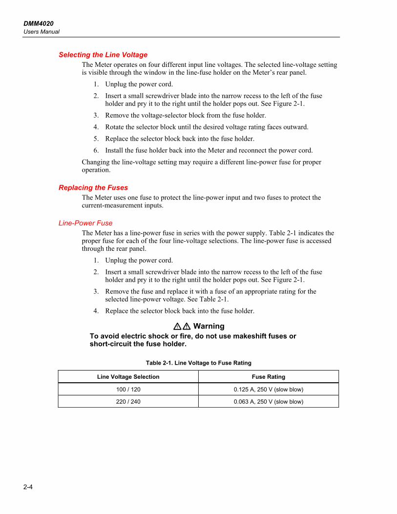
Line-Power Fuse The Meter has a line-power fuse in series with the power supply. Table 2-1 indicates the proper fuse for each of the four line-voltage selections. The line-power fuse is accessed through the rear panel.
1. Unplug the power cord. 2. Insert a small screwdriver blade into the narrow recess to the left of the fuse
holder and pry it to the right until the holder pops out. See Figure 2-1. 3. Remove the fuse and replace it with a fuse of an appropriate rating for the
selected line-power voltage. See Table 2-1. 4. Replace the selector block back into the fuse holder.
XW Warning To avoid electric shock or fire, do not use makeshift fuses or short-circuit the fuse holder.
Table 2-1. Line Voltage to Fuse Rating
Line Voltage Selection Fuse Rating
100 / 120 0.125 A, 250 V (slow blow)
220 / 240 0.063 A, 250 V (slow blow)

Preparing the Meter for Operation Power Considerations 2
2-5
120
eue20.eps
Figure 2-1. Replacing the Line Power Fuse
Current-Input Fuses The 200 mA and 10 A inputs are protected by user-replaceable fuses.
• The 200 mA input is protected by a fuse (F2) rated at 440 mA, 1000 V (fast blow), 10,000 A minimum breaking capacity.
• The 10 A input is protected by a fuse (F1) rated at 11 A, 1000 V (fast blow), 10,000 A minimum breaking capacity.
XW Warning For protection against fire or arc flash, replace a blown fuse with a fuse of an identical rating.
To test the current-input fuses: 1. Turn on the Meter and plug a test lead into the INPUT VZYR HI terminal. 2. Press O. 3. Press V to set the range to 200 Ω. Only the 200 Ω, 2 kΩ, and 20 kΩ ranges
can be used to test the mA input fuse. 4. Insert the other end of the test lead into the mA terminal. If the fuse is good, the
Meter displays a reading of <10 Ω. If the fuse is blown, the Meter displays 0L to indicate an overload.
5. Remove the test lead from the mA terminal and insert it into the 10 A terminal. If the fuse is good, the Meter displays a reading of <2 Ω. If the fuse is blown, the Meter displays 0L to indicate an overload.
XW Warning To avoid electric shock, remove the power cord and any test leads from the Meter before opening the current-input fuse cover.
DMM4020 Users Manual
2-6
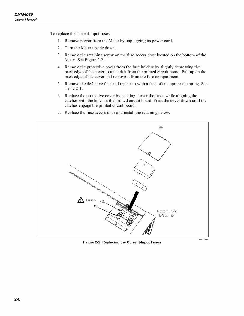
To replace the current-input fuses: 1. Remove power from the Meter by unplugging its power cord. 2. Turn the Meter upside down. 3. Remove the retaining screw on the fuse access door located on the bottom of the
Meter. See Figure 2-2. 4. Remove the protective cover from the fuse holders by slightly depressing the
back edge of the cover to unlatch it from the printed circuit board. Pull up on the back edge of the cover and remove it from the fuse compartment.
5. Remove the defective fuse and replace it with a fuse of an appropriate rating. See Table 2-1.
6. Replace the protective cover by pushing it over the fuses while aligning the catches with the holes in the printed circuit board. Press the cover down until the catches engage the printed circuit board.
7. Replace the fuse access door and install the retaining screw.
Fuses F2F1
Bottom frontleft corner
eue04.eps
Figure 2-2. Replacing the Current-Input Fuses
Preparing the Meter for Operation Connecting to Line Power 2
2-7
Connecting to Line Power XW Warning
To avoid shock hazard, connect the factory supplied three-conductor line power cord to a properly grounded power outlet. Do not use a two-conductor adapter or extension cord, as this will break the protective ground connection. If a two-conductor power cord must be used, a protective grounding wire must be connected between the ground terminal and earth ground before connecting the power cord or operating the Meter.
1. Verify that the line voltage selector block is set to the correct setting. 2. Verify that the correct fuse for the line voltage is installed. 3. Connect the power cord to a properly grounded three-prong outlet. Refer to Table
2-2 for descriptions of the line-power cords available from Tektronix.
Table 2-2. Line Power Cord Types Available from Tektronix
Type Voltage / Current Tektronix Part Number
North America 120 V / 15 A 161-0066-00
North America 250 V / 10 A 161-0066-12
Universal Euro 250 V / 10 A 161-0066-09
United Kingdom 250 V / 10 A 161-0066-10
Switzerland 250 V / 10 A 161-0154-00
Australia 250 V / 10 A 161-0066-13
Japan 125V / 7A 161-0298-00
China 250V / 10A 161-0304-00
Turning Power On 1. If required, connect the Meter to line power. 2. Toggle the power switch on the rear panel so the “I” side of the switch is
depressed. The Meter will turn on and briefly illuminate all LCD segments.
Note To save on power consumption, the Meter can be set to a standby mode by pressing P on the front panel. Press it again to bring the Meter up to full power.
DMM4020 Users Manual
2-8
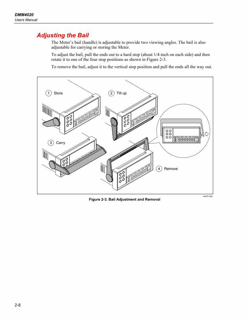
Adjusting the Bail The Meter’s bail (handle) is adjustable to provide two viewing angles. The bail is also adjustable for carrying or storing the Meter. To adjust the bail, pull the ends out to a hard stop (about 1/4-inch on each side) and then rotate it to one of the four stop positions as shown in Figure 2-3. To remove the bail, adjust it to the vertical stop position and pull the ends all the way out.
1 Store
3 Carry
4 Remove
2 Tilt up
eue21.eps
Figure 2-3. Bail Adjustment and Removal

Preparing the Meter for Operation Installing the Meter into an Equipment Rack 2
2-9
Installing the Meter into an Equipment Rack The Meter is mountable in a standard 19-inch rack using a rack mount kit. See the “Accessories” section in Chapter 1 for ordering information. To prepare the Meter for rack mounting, remove the bail and remove the front and rear protective boots. To remove a boot, stretch a corner then slide it off as shown in Figure 2-4. To install the Meter into the rack, refer to the instructions provided with the Rack Mount Kit.
eue22.eps
Figure 2-4. Boot Removal
Cleaning the Meter XW Warning
To avoid electric shock or damage to the Meter, never get water inside the Meter.
W Caution To avoid damaging the Meter’s housing, do not apply solvents to the Meter.
If the Meter requires cleaning, wipe it down with a cloth that is lightly dampened with water or a mild detergent. Do not use aromatic hydrocarbons, alcohol, chlorinated solvents, or methanol-based fluids when wiping down the Meter.
DMM4020 Users Manual
2-10
Fluke 45 Emulation Mode The Fluke 45 emulation mode enables you to use programs that run on the Fluke 45 multimeter model on the Tektronix DMM4020. To switch the Meter to Fluke 45 emulation:
1. Press and hold S and f for two seconds. 2. Press U or V to scroll between 4020 and Fluke 45. The presently selected
mode will appear bright in the display, while the other is dim. 3. Press R to set the mode and reset the Meter.
Illuminating All Display Segments To illuminate all display segments, start with the Meter display off. Next, press and hold S then press P to turn on the Meter. Release the buttons when the display illuminates. To return to normal measurement mode, press S.
3-1
Chapter 3 Operating the Meter from the Front Panel
Title Page
Introduction.......................................................................................................... 3-3 Dual Display ........................................................................................................ 3-6
Primary Display............................................................................................... 3-6 Secondary Display........................................................................................... 3-6
Rear Panel ............................................................................................................ 3-8 Adjusting Meter Range ........................................................................................ 3-9 Selecting a Measurement Rate............................................................................. 3-9 Selecting a Measurement Function...................................................................... 3-9
Measuring Voltage .......................................................................................... 3-9 Measuring Frequency ...................................................................................... 3-10 Frequency Ranging.......................................................................................... 3-10 Measuring Resistance...................................................................................... 3-10
2-Wire Resistance Measurement................................................................. 3-11 4-Wire Resistance Measurement................................................................. 3-12
Measuring Current........................................................................................... 3-13 Automatic Input Terminal Detection............................................................... 3-14 Diode / Continuity Testing .............................................................................. 3-14 Making a Triggered Measurement .................................................................. 3-16
Setting the Trigger Mode ............................................................................ 3-16 Connecting to an External Trigger .............................................................. 3-16
Selecting a Function Modifier ............................................................................. 3-18 Relative Readings Modifier (REL).................................................................. 3-18 Decibels and Auto Power Modifier ................................................................. 3-18 Touch Hold Function (HOLD) ........................................................................ 3-19 Minimum / Maximum Modifier (MIN MAX) ................................................ 3-20 Using the Function Modifiers in Combination................................................ 3-21 Second Level Operations (Using the SHIFT Button)...................................... 3-21
Compare Function (COMP)................................................................................. 3-22 Setting the Compare Range ............................................................................. 3-22 Using the Compare Function........................................................................... 3-22
List and Number Editors...................................................................................... 3-22 Using the List Editor ....................................................................................... 3-23 Using the Number Editor................................................................................. 3-23
Function Keys S1 – S6......................................................................................... 3-24 Power-Up Configuration...................................................................................... 3-25 Calibration ........................................................................................................... 3-25

DMM4020 Users Manual
3-2
Operating the Meter from the Front Panel Introduction 3
3-3
Introduction The Meter can be controlled either by sending commands through its RS232 communication interface or through the front panel. This chapter explains the function and use of the controls and indicators located on the front panel of the Meter. Operating the Meter through its RS232 communication interface is covered in Chapter 4. The front panel has three main elements: input terminals (on the left), dual display (primary and secondary displays), and keypad. See Figure 3-1 for an overview of the front panel and refer to Table 3-1 for descriptions of the front-panel features. The front panel is used to:
• Select a measurement function (volts dc, volts ac, current dc, current ac, resistance, frequency, and diode/continuity test) for the primary and/or secondary displays
• Take a measurement and display a reading • Select the manual or autorange mode • Manually select a measurement range for the primary display • Select function modifiers that cause the Meter to display relative readings,
minimum or maximum values, or to select the TouchHold® function to hold a reading on the primary display
• Change the measurement rate (slow, medium, fast) • Take a measurement and compare it against a tolerance range • Use the editor to select from option lists, to enter a relative base, or to enter a
high (HI) or low (LO) range for the compare mode • Configure the computer interface (RS-232) • Send measurements directly to a printer or terminal through the RS-232 interface

DMM4020 Users Manual
3-4
5-1/2 DIGIT MULTIMETER
HI
LO
1000V 750V
2W/4W
MAX
INPUT SENSE
HI
LO
4W
10AmA
200 mAMAX 10A
MAX
1000 V CAT I 600 V CAT II
500 V pk
V
1V
300V
1
17 16
2
67891011121314155
4
TEKTRONIX DMM4020
3
gdb02.eps
Figure 3-1. Front Panel
Table 3-1. Front-Panel Features
No. Name Description
A INPUT VZYR HI, LO Input terminals for Volts, 2-Wire and 4-Wire Ohms, and Hz measurements. All measurements use the INPUT LO terminal as a common input. The LO input is isolated and may be safely floated up to 500 V peak above earth ground regardless of the measurement type. 1000 V dc is the maximum voltage rating between the INPUT HI and LO terminals.
B SENSE 4WZ HI, LO 4-wire Ohms measurement sense terminal
C C Compare function for determining if a reading falls within a designated range of values
D abcdef For storage and retrieval of up to six test configurations
E CAL (recessed button) Calibrates Meter
F P Activates/deactivates standby mode for power savings
G Q Activates second level operation for function buttons
Locks the front panel operation during remote mode
H K Primary operation: Selects Meter print mode
Second level operation: Sets RS-232 communication parameters (baud rate, parity, echo)

Operating the Meter from the Front Panel Introduction 3
3-5
3-1. Front-Panel Features (cont.)
No. Name Description
I J Primary operation: Sets the Meter’s measurement rate to slow, medium or fast
Second level operation: Selects source for triggering measurement
J I Primary operation: Selects Touch Hold function
Second level operation: Sets Touch Hold minimum response level
K T Primary operation: Selects relative readings function to display difference between relative base and input
Second level operation: Sets relative base
L W Primary operation: Selects dB measurement mode
Second level operation: sets dB reference impedance
M N Stores the minimum and maximum inputs measured
N F D A E B O G
Selects measurement function:
Frequency DC voltage AC voltage DC current AC current Resistance (ohms) Continuity / diode test (toggles)
O R Toggles between manual and autorange modes
Uand V increase and decrease the range for manual ranging
P 10 A Input terminal for 10 A ac and dc current measurement
Q mA Input terminal for 200 mA ac and dc current measurement

DMM4020 Users Manual
3-6
Dual Display The Meter has a 5-1/2 digit vacuum fluorescent dual display. See Figure 3-2 and Table 3-2 for an overview of the display annunciators and indicators. The dual display is comprised of a primary display and a secondary display, which show measurement readings, annunciators and messages. The annunciators indicate measurement units and the Meter’s operating configuration. The dual display allows you to see two properties for the input signal you are measuring. The Meter alternates between properties, measuring the first property and showing it on one display, and then measuring the second property and showing it on the other display. (For more detail, see the “How the Meter Takes Dual Display Measurements” section in Appendix A.) If an input exceeds the full-scale value of the selected range, the Meter displays 0Lto indicate an overload.
Primary Display The primary display comprises the lower segment of the dual display, and consists of the larger digits and annunciators. The primary display shows measurements taken using the relative readings (REL), minimum maximum (MIN MAX), Touch Hold (HOLD), and decibels (dB) function modifiers.
Secondary Display The secondary display comprises the upper segment of the dual display, and consists of the smaller digits and annunciators. Function modifiers REL, HOLD, MIN MAX, and dB and the manual range mode cannot be selected for the secondary display. The secondary display is either in autorange, or the same range as the primary display if both displays are in the same function.
1 2 3 4 5 76 8 9 1110 12
13
14
15
1718
19
20
21
22
24
23
16
eue01f.eps
Figure 3-2. Display Annunciators and Indicators
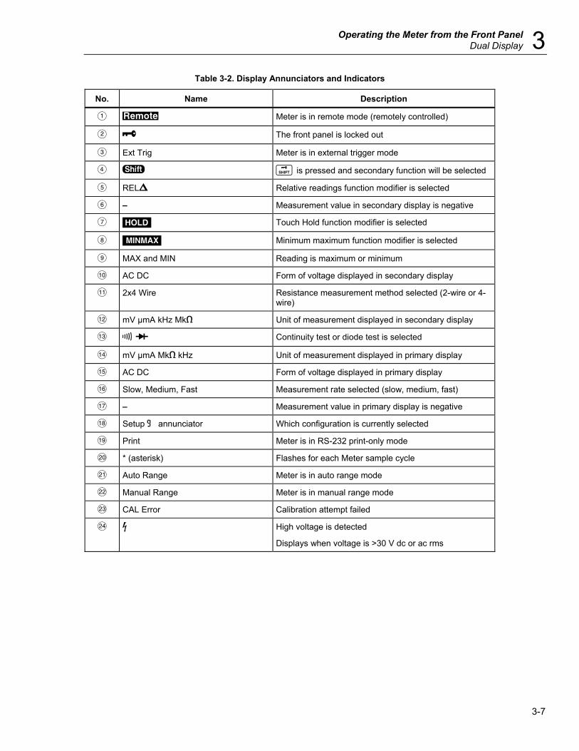
Operating the Meter from the Front Panel Dual Display 3
3-7
Table 3-2. Display Annunciators and Indicators
No. Name Description
A r Meter is in remote mode (remotely controlled)
B L The front panel is locked out
C Ext Trig Meter is in external trigger mode
D S Q is pressed and secondary function will be selected
E RELX Relative readings function modifier is selected
F – Measurement value in secondary display is negative
G H Touch Hold function modifier is selected
H M Minimum maximum function modifier is selected
I MAX and MIN Reading is maximum or minimum
J AC DC Form of voltage displayed in secondary display
K 2x4 Wire Resistance measurement method selected (2-wire or 4-wire)
L mV µmA kHz Mke Unit of measurement displayed in secondary display
M R G Continuity test or diode test is selected
N mV µmA Mke kHz Unit of measurement displayed in primary display
O AC DC Form of voltage displayed in primary display
P Slow, Medium, Fast Measurement rate selected (slow, medium, fast)
Q – Measurement value in primary display is negative
R Setup 8 annunciator Which configuration is currently selected
S Print Meter is in RS-232 print-only mode
T * (asterisk) Flashes for each Meter sample cycle
U Auto Range Meter is in auto range mode
V Manual Range Meter is in manual range mode
W CAL Error Calibration attempt failed
X Y High voltage is detected
Displays when voltage is >30 V dc or ac rms

DMM4020 Users Manual
3-8
Rear Panel See Figure 3-3 and Table 3-3 for an overview of the rear-panel features.
220
TEKTRONIX CORPORATIONMade in China
N60
LR44340
www.tektronix.com
1 2 3
45
gdb03.eps
Figure 3-3. Rear Panel
Table 3-3. Rear-Panel Features
No. Name Description
A Line power terminal Connects Meter to power source via power cord
B Power switch Turns power on and off to the Meter
C Fuse holder and power line voltage selector
Houses fuses:
1/8 A slow fuse, 100/120 VAC
1/16 A slow fuse, 220/240 VAC
Provides means to select line power voltage:
100 Vac, 120 Vac, 220 Vac, 240 Vac
D RS-232 terminal RS-232 and External trigger terminal. Connects Meter to a host, serial printer or terminal, and provides external trigger interface.
E Ground terminal Provides connection to ground

Operating the Meter from the Front Panel Adjusting Meter Range 3
3-9
Adjusting Meter Range Ranging operations are performed using R, Uand V. Press R to toggle between autorange and manual range modes. When autoranging is selected, Auto Range is displayed. When manual ranging is selected, Manual Range is displayed. In autoranging mode, the Meter automatically selects the next higher range when a reading is greater than full-scale. If no higher range is available, 0L is displayed on the primary or secondary display to indicate an overload. The Meter automatically selects a lower range when a reading is less than 95 % of full-scale of the lower range. In autoranging mode, pressing U or V changes the mode to manual ranging. If U is pressed, the next higher range is selected (if there is one). If V is pressed, the next lower range is selected. In manual ranging mode, the range that is set when you enter the mode becomes the selected range. The Meter remains in the selected range regardless of input. Manual ranging can only be performed on readings shown on the primary display. The secondary display is in autorange or when the primary and secondary displays are set to the same function, the secondary display uses the same range as the primary display.
Selecting a Measurement Rate The Meter takes measurements at one of three user-selected rates: slow, medium, and fast. Rate selection allows you to maximize measurement speed, which can affect accuracy. The rate selected is shown in the primary display as Slow, Medium, or Fast. Press J to step through the measurement rates. The rate selected applies to all basic measurements except frequency. When frequency is measured, the rate is fixed at 4 measurements per second. Pressing J does not affect the frequency update rate.The measurement rate is always fast for Diode and Continuity test.
Selecting a Measurement Function To select a measurement function, press the applicable function button (See Table 3-1). The applicable annunciator is displayed to indicate the selected function. (For example, to measure dc voltage, press D. DC is displayed.) To select ac + dc total rms readings, simultaneously press A and D for more than two seconds; or simultaneously press B and E for more than two seconds. If a reading is shown on the secondary display when a function button is pressed, the secondary display turns off and that function is selected for the primary display.
Measuring Voltage The Meter is capable of measuring voltage up to 1000 V dc and 750 V ac.
W Caution To avoid possible damage to the Meter, do not apply voltage to the Meter’s inputs until the test leads are properly connected and the proper voltage function is selected.
To perform a voltage measurement: 1. Connect test leads between the Meter and the circuit under test as shown in
Figure 3-4. 2. Press D to measure dc voltage or A to measure ac voltage.
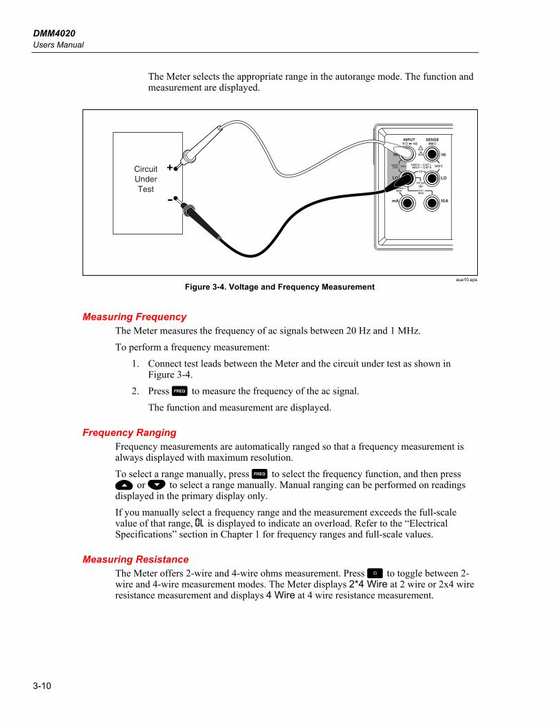
DMM4020 Users Manual
3-10
The Meter selects the appropriate range in the autorange mode. The function and measurement are displayed.
HI
LO
1000V 750V
2W/4W
MAX
INPUT SENSE
HI
LO
4W
10AmA
200 mAMAX 10A
MAX
1000 V CAT I 600 V CAT II
500 V pk
V
1V
300VCircuitUnderTest
eue10.eps
Figure 3-4. Voltage and Frequency Measurement
Measuring Frequency The Meter measures the frequency of ac signals between 20 Hz and 1 MHz. To perform a frequency measurement:
1. Connect test leads between the Meter and the circuit under test as shown in Figure 3-4.
2. Press F to measure the frequency of the ac signal. The function and measurement are displayed.
Frequency Ranging Frequency measurements are automatically ranged so that a frequency measurement is always displayed with maximum resolution. To select a range manually, press F to select the frequency function, and then press U or V to select a range manually. Manual ranging can be performed on readings displayed in the primary display only. If you manually select a frequency range and the measurement exceeds the full-scale value of that range, 0L is displayed to indicate an overload. Refer to the “Electrical Specifications” section in Chapter 1 for frequency ranges and full-scale values.
Measuring Resistance The Meter offers 2-wire and 4-wire ohms measurement. Press O to toggle between 2-wire and 4-wire measurement modes. The Meter displays 2*4 Wire at 2 wire or 2x4 wire resistance measurement and displays 4 Wire at 4 wire resistance measurement.
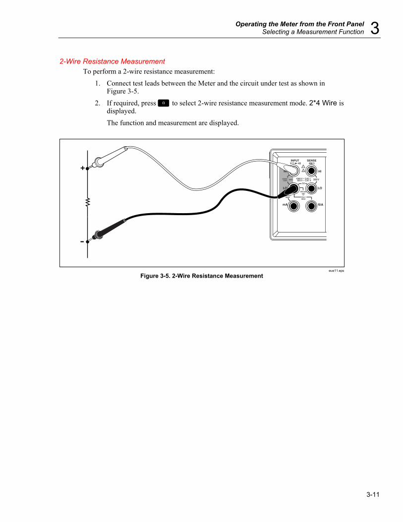
Operating the Meter from the Front Panel Selecting a Measurement Function 3
3-11
2-Wire Resistance Measurement To perform a 2-wire resistance measurement:
1. Connect test leads between the Meter and the circuit under test as shown in Figure 3-5.
2. If required, press O to select 2-wire resistance measurement mode. 2*4 Wire is displayed. The function and measurement are displayed.
HI
LO
1000V 750V
2W/4W
MAX
INPUT SENSE
HI
LO
4W
10AmA
200 mAMAX 10A
MAX
1000 V CAT I 600 V CAT II
500 V pk
V
1V
300V
eue11.eps
Figure 3-5. 2-Wire Resistance Measurement

DMM4020 Users Manual
3-12
4-Wire Resistance Measurement The Meter incorporates two methods of making a four-wire resistance measurement. The traditional method is to use four meter leads to connect the Meter to the resistance to be measured. The optional 2X4 Wire test leads simplifies the four-wire measurement so you only have to plug in two test leads to the Input HI and LO connectors of the meter. To perform a 4-wire resistance measurement using four test leads:
1. Connect test leads between the Meter and the circuit under test as shown in Figure 3-6.
2. If required, press O to select 4-wire resistance measurement mode. 4 Wire is displayed. The function and measurement are displayed.
22
HI
LO
1000V 750V
2W/4W
MAX
INPUT SENSE
HI
LO
4W
10AmA
200 mAMAX 10A
MAX
1000 V CAT I 600 V CAT II
500 V pk
V
1V
300V
eue12.eps
Figure 3-6. 4-Wire Resistance Measurement
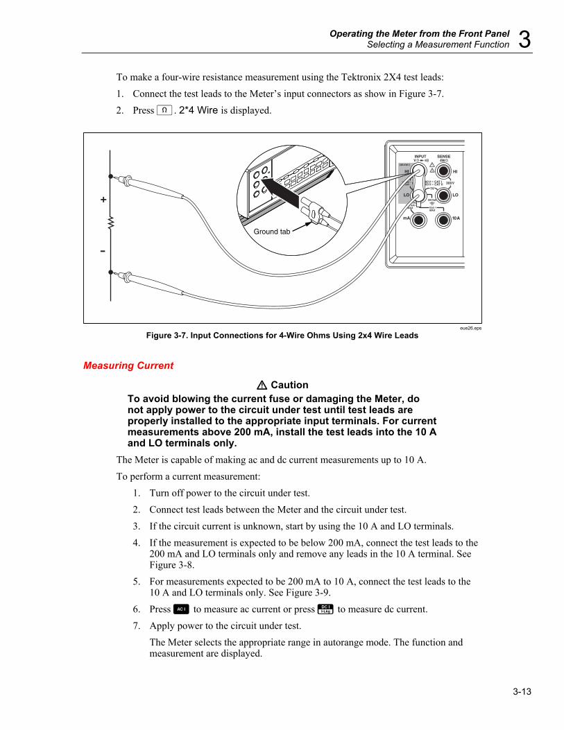
Operating the Meter from the Front Panel Selecting a Measurement Function 3
3-13
To make a four-wire resistance measurement using the Tektronix 2X4 test leads: 1. Connect the test leads to the Meter’s input connectors as show in Figure 3-7. 2. Press N. 2*4 Wire is displayed.
HI
LO
1000V 750V
2W/4W
MAX
INPUT SENSE
HI
LO
4W
10AmA
200 mAMAX 10A
MAX
1000 V CAT I 600 V CAT II
500 V pk
V
1V
300V
Ground tab
eue26.eps
Figure 3-7. Input Connections for 4-Wire Ohms Using 2x4 Wire Leads
Measuring Current
W Caution To avoid blowing the current fuse or damaging the Meter, do not apply power to the circuit under test until test leads are properly installed to the appropriate input terminals. For current measurements above 200 mA, install the test leads into the 10 A and LO terminals only.
The Meter is capable of making ac and dc current measurements up to 10 A. To perform a current measurement:
1. Turn off power to the circuit under test. 2. Connect test leads between the Meter and the circuit under test. 3. If the circuit current is unknown, start by using the 10 A and LO terminals. 4. If the measurement is expected to be below 200 mA, connect the test leads to the
200 mA and LO terminals only and remove any leads in the 10 A terminal. See Figure 3-8.
5. For measurements expected to be 200 mA to 10 A, connect the test leads to the 10 A and LO terminals only. See Figure 3-9.
6. Press B to measure ac current or press E to measure dc current. 7. Apply power to the circuit under test.
The Meter selects the appropriate range in autorange mode. The function and measurement are displayed.
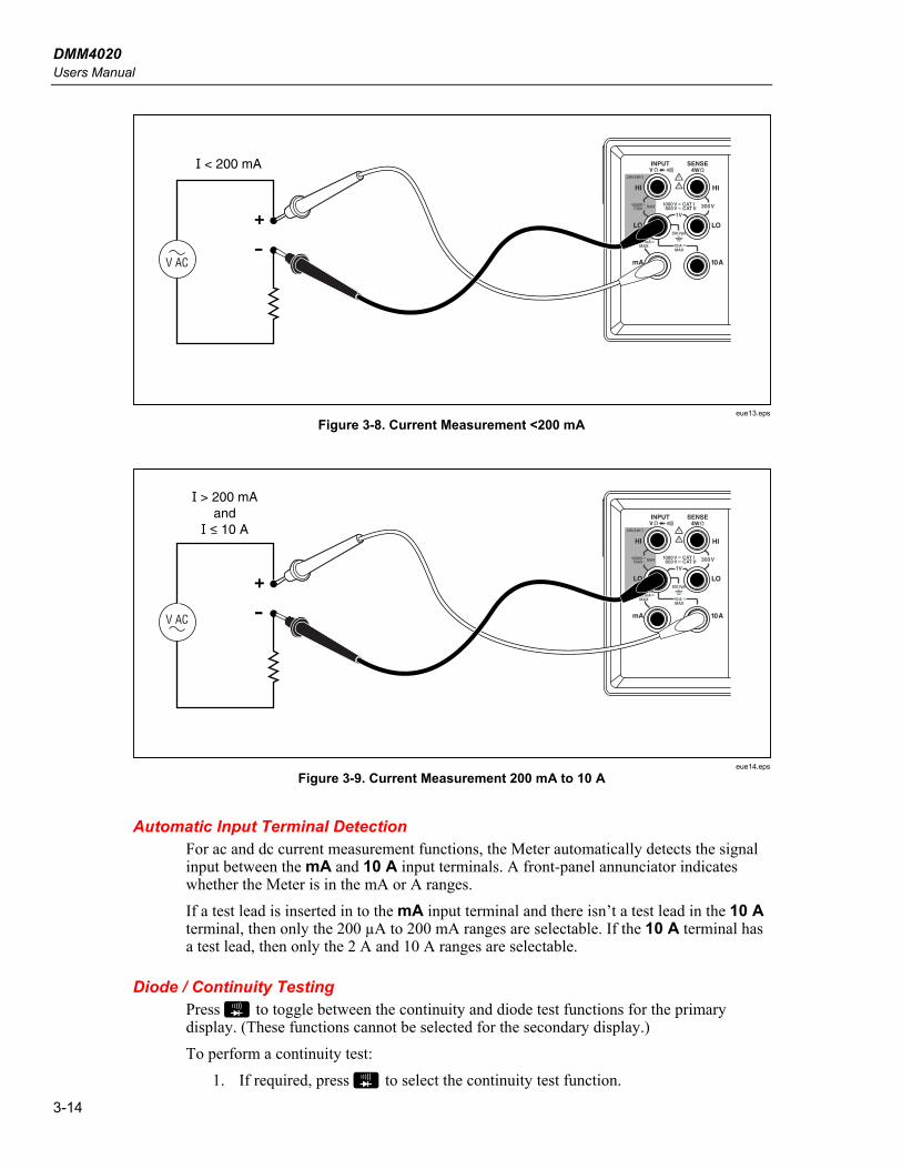
DMM4020 Users Manual
3-14
HI
LO
1000V 750V
2W/4W
MAX
INPUT SENSE
HI
LO
4W
10AmA
200 mAMAX 10A
MAX
1000 V CAT I 600 V CAT II
500 V pk
V
1V
300V
V AC
I < 200 mA
eue13.eps
Figure 3-8. Current Measurement <200 mA
HI
LO
1000V 750V
2W/4W
MAX
INPUT SENSE
HI
LO
4W
10AmA
200 mAMAX 10A
MAX
1000 V CAT I 600 V CAT II
500 V pk
V
1V
300V
V AC
I > 200 mAand
I < 10 A
eue14.eps
Figure 3-9. Current Measurement 200 mA to 10 A
Automatic Input Terminal Detection For ac and dc current measurement functions, the Meter automatically detects the signal input between the mA and 10 A input terminals. A front-panel annunciator indicates whether the Meter is in the mA or A ranges. If a test lead is inserted in to the mA input terminal and there isn’t a test lead in the 10 A terminal, then only the 200 µA to 200 mA ranges are selectable. If the 10 A terminal has a test lead, then only the 2 A and 10 A ranges are selectable.
Diode / Continuity Testing Press G to toggle between the continuity and diode test functions for the primary display. (These functions cannot be selected for the secondary display.) To perform a continuity test:
1. If required, press G to select the continuity test function.

Operating the Meter from the Front Panel Selecting a Measurement Function 3
3-15
2. Connect the test leads between the Meter and the circuit under test as shown in Figure 3-10. The beeper emits a continuous tone if the input is below 20 Ω.
To perform a diode or transistor junction test: 1. If required, press G to select the diode test function. 2. Connect the test leads between the Meter and the diode or transistor junction as
shown in Figure 3-11. The forward voltage of the semiconductor junction (or junctions) is measured. Readings are displayed in the 2 V range at the fast measurement rate. The Meter displays 0L if the input is above +2 V.
HI
LO
1000V 750V
2W/4W
MAX
INPUT SENSE
HI
LO
4W
10AmA
200 mAMAX 10A
MAX
1000 V CAT I 600 V CAT II
500 V pk
V
1V
300V
eue15.eps
Figure 3-10. Continuity Test
HI
LO
1000V 750V
2W/4W
MAX
INPUT SENSE
HI
LO
4W
10AmA
200 mAMAX 10A
MAX
1000 V CAT I 600 V CAT II
500 V pk
V
1V
300V
eue16.eps
Figure 3-11. Diode Test

DMM4020 Users Manual
3-16
Making a Triggered Measurement The Meter features a trigger function that allows you to select a measurement trigger source. When the trigger mode is set to 3 or 5, the delay between receiving the trigger and the start of a measurement is 400 ms. Refer to Chapter 1 for trigger delay response specifications. Upon completion of each measurement, a “measurement-complete” signal (low-true pulse) is sent to the external trigger terminal on the rear panel. See the “Electrical Specifications” section in Chapter 1 for information on this signal. The following sections discuss triggering the Meter automatically using its internal trigger, or externally using the trigger key on the front panel and the trigger terminal on the rear panel.
Setting the Trigger Mode There are five possible sources for triggering a measurement:
• Mode 1 is automatic. Measurements are triggered internally and are continuous and occur as fast as the configuration will allow.
• Mode 2 is triggered without delay using J. • Mode 3 is triggered with delay using J. • Mode 4 is triggered without delay by an external signal. • Mode 5 is triggered with delay by an external signal.
To select a trigger source: 1. Press Q then J. 2. Press U or V to choose the trigger mode. 3. Press R and hold for 2 seconds to save the selected mode.
Connecting to an External Trigger The Meter provides two external trigger connection methods for different operation modes. Table 3-4 shows the layout of the TRIG/IO_RS232 connector. An external TTL signal on pin 9 will trigger a measurement cycle. Alternatively, pin 9 of the RS-232 interface can be connected to pin 1 through an external switch. See Figure 3-12. A measurement cycle is trigger when the switch is closed and the +5 volts from pin 1 is applied to pin 9. The trigger event occurs on the rising edge of the signal applied to pin 9.

Operating the Meter from the Front Panel Selecting a Measurement Function 3
3-17
Table 3-4. RS-232 Pin Out
1 2 3 4
6 7 8 9
5
eue23.eps
Pin # Description Pin # Description
1 +5 V OUT 2 RS-232 RXD
3 RS-232 TXD 5 RS-232 GND
6 Trigger Out 9 Trigger In
Figure 3-12 shows a method for using the +5 V OUT (pin 1) signal with an external switch to trigger the Meter.
+5 V Out (Pin 1)
Trig In (Pin 9)
eue24.eps
Figure 3-12. External Trigger Circuit
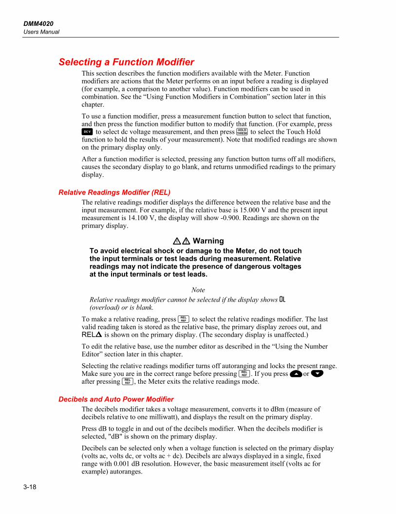
DMM4020 Users Manual
3-18
Selecting a Function Modifier This section describes the function modifiers available with the Meter. Function modifiers are actions that the Meter performs on an input before a reading is displayed (for example, a comparison to another value). Function modifiers can be used in combination. See the “Using Function Modifiers in Combination” section later in this chapter. To use a function modifier, press a measurement function button to select that function, and then press the function modifier button to modify that function. (For example, press D to select dc voltage measurement, and then press I to select the Touch Hold function to hold the results of your measurement). Note that modified readings are shown on the primary display only. After a function modifier is selected, pressing any function button turns off all modifiers, causes the secondary display to go blank, and returns unmodified readings to the primary display.
Relative Readings Modifier (REL) The relative readings modifier displays the difference between the relative base and the input measurement. For example, if the relative base is 15.000 V and the present input measurement is 14.100 V, the display will show -0.900. Readings are shown on the primary display.
XW Warning To avoid electrical shock or damage to the Meter, do not touch the input terminals or test leads during measurement. Relative readings may not indicate the presence of dangerous voltages at the input terminals or test leads.
Note Relative readings modifier cannot be selected if the display shows 0L (overload) or is blank.
To make a relative reading, press T to select the relative readings modifier. The last valid reading taken is stored as the relative base, the primary display zeroes out, and RELX is shown on the primary display. (The secondary display is unaffected.) To edit the relative base, use the number editor as described in the “Using the Number Editor” section later in this chapter. Selecting the relative readings modifier turns off autoranging and locks the present range. Make sure you are in the correct range before pressing T. If you press Uor V after pressing T, the Meter exits the relative readings mode.
Decibels and Auto Power Modifier The decibels modifier takes a voltage measurement, converts it to dBm (measure of decibels relative to one milliwatt), and displays the result on the primary display. Press dB to toggle in and out of the decibels modifier. When the decibels modifier is selected, "dB" is shown on the primary display. Decibels can be selected only when a voltage function is selected on the primary display (volts ac, volts dc, or volts ac + dc). Decibels are always displayed in a single, fixed range with 0.001 dB resolution. However, the basic measurement itself (volts ac for example) autoranges.
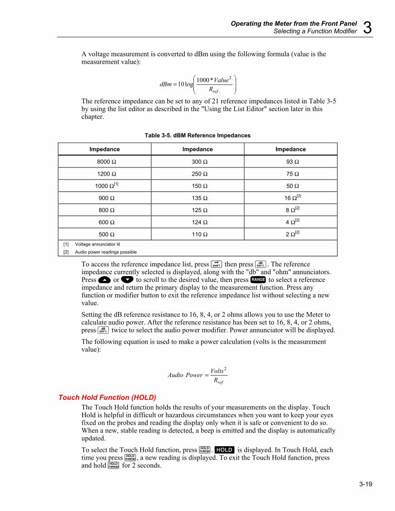
Operating the Meter from the Front Panel Selecting a Function Modifier 3
3-19
A voltage measurement is converted to dBm using the following formula (value is the measurement value):
⎟⎟⎠
⎞⎜⎜⎝
⎛=
.
2*1000log10refRValuedBm
The reference impedance can be set to any of 21 reference impedances listed in Table 3-5 by using the list editor as described in the "Using the List Editor" section later in this chapter.
Table 3-5. dBM Reference Impedances
Impedance Impedance Impedance
8000 Ω 300 Ω 93 Ω
1200 Ω 250 Ω 75 Ω
1000 Ω[1] 150 Ω 50 Ω
900 Ω 135 Ω 16 Ω[2]
800 Ω 125 Ω 8 Ω[2]
600 Ω 124 Ω 4 Ω[2]
500 Ω 110 Ω 2 Ω[2] [1] Voltage annunciator lit
[2] Audio power readings possible
To access the reference impedance list, press Q then press W. The reference impedance currently selected is displayed, along with the "db" and "ohm" annunciators. Press U or V to scroll to the desired value, then press R to select a reference impedance and return the primary display to the measurement function. Press any function or modifier button to exit the reference impedance list without selecting a new value. Setting the dB reference resistance to 16, 8, 4, or 2 ohms allows you to use the Meter to calculate audio power. After the reference resistance has been set to 16, 8, 4, or 2 ohms, press W twice to select the audio power modifier. Power annunciator will be displayed. The following equation is used to make a power calculation (volts is the measurement value):
refRVoltsPowerAudio
2=
Touch Hold Function (HOLD) The Touch Hold function holds the results of your measurements on the display. Touch Hold is helpful in difficult or hazardous circumstances when you want to keep your eyes fixed on the probes and reading the display only when it is safe or convenient to do so. When a new, stable reading is detected, a beep is emitted and the display is automatically updated. To select the Touch Hold function, press I. H is displayed. In Touch Hold, each time you press I, a new reading is displayed. To exit the Touch Hold function, press and hold I for 2 seconds.

DMM4020 Users Manual
3-20
If you are in the autorange mode when Touch Hold is selected, you will autorange to the correct range. If you are in the manual range mode when Touch Hold is selected, you will be in the fixed range you were in when Touch Hold was selected. The Touch Hold function can be combined with the minimum/maximum modifier to hold and update only when a new minimum or maximum value is detected. To force the display to update, with Touch Hold selected press I for less than 2 seconds. The Meter allows you to choose the minimum response level needed for Touch Hold to capture and display a measurement. You can choose from the following four response levels:
• Level 1 (5 % of range) • Level 2 (7 % of range) • Level 3 (8 % of range)
To change the response level, press Q and I. The response level currently selected (1, 2, 3 or 4) appears on the primary display. Press U or V to step to the desired response level, then press R for two seconds to set the level and return to the primary display. You can return to the primary display without changing the response level by pressing any button except R, U or V.
Minimum / Maximum Modifier (MIN MAX) The minimum/maximum (MIN MAX) modifier stores the minimum and maximum inputs of your measurements. Selecting the MIN MAX modifier turns off autoranging and locks in the present range, so make sure you are in the correct range before pressing N. If you press U or V after pressing N, the Meter exits the MIN MAX modifier mode. To store the minimum and maximum inputs:
1. Press N to select the MIN MAX modifier. When N is first pressed, the minimum and maximum values are set to the reading displayed. MAX is shown and the display indicates the latest maximum reading.
2. Press N again to display the minimum reading. MIN is shown and the display indicates the latest minimum reading.
3. Press N again to display either the minimum or maximum reading. M is shown and the display indicates either the minimum or maximum reading.
4. To exit MIN MAX mode, press and hold N for 2 seconds. 5. To observe the actual readings without resetting the stored values, press Q and
then select the same measurement function that you selected for the primary display.
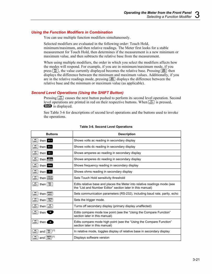
Operating the Meter from the Front Panel Selecting a Function Modifier 3
3-21
Using the Function Modifiers in Combination You can use multiple function modifiers simultaneously. Selected modifiers are evaluated in the following order: Touch Hold, minimum/maximum, and then relative readings. The Meter first looks for a stable measurement for Touch Hold, then determines if the measurement is a new minimum or maximum value, and then subtracts the relative base from the measurement. When using multiple modifiers, the order in which you select the modifiers affects how the modes will respond. For example, if you are in minimum/maximum mode, if you press T, the value currently displayed becomes the relative base. Pressing N then displays the difference between the minimum and maximum values. Additionally, if you are in the relative readings mode, pressing N displays the difference between the relative base and the minimum or maximum value (as applicable).
Second Level Operations (Using the SHIFT Button) Pressing Q causes the next button pushed to perform its second level operation. Second level operations are printed in red on their respective buttons. When Q is pressed, S is displayed. See Table 3-6 for descriptions of second level operations and the buttons used to invoke the operations.
Table 3-6. Second Level Operations
Buttons Description
Q then A Shows volts ac reading in secondary display
Q then D Shows volts dc reading in secondary display
Q then B Shows amperes ac reading in secondary display
Q then E Shows amperes dc reading in secondary display
Q then F Shows frequency reading in secondary display
Q then O Shows ohms reading in secondary display
Q then I Sets Touch Hold sensitivity threshold
Q then T Edits relative base and places the Meter into relative readings mode (see the “List and Number Editor” section later in this manual)
Q then K Sets communication parameters (RS-232), including baud rate, parity, echo
Q then J Sets the trigger mode.
Q then Q Turns off secondary display (primary display unaffected)
Q then V Edits compare mode low point (see the “Using the Compare Function” section later in this manual)
Q then U Edits compare mode high point (see the “Using the Compare Function” section later in this manual)
Q and T[1] In relative mode, toggles display of relative base in secondary display
Q and J[1] Displays software version
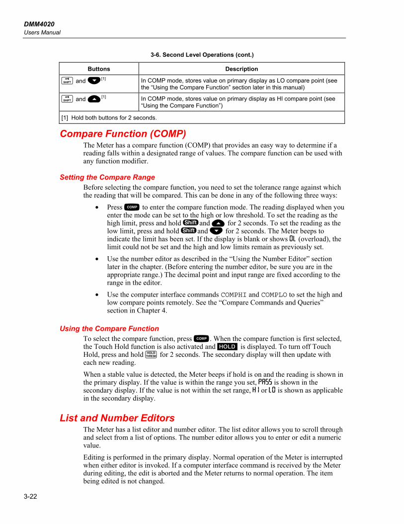
DMM4020 Users Manual
3-22
3-6. Second Level Operations (cont.)
Buttons Description
Q and V[1] In COMP mode, stores value on primary display as LO compare point (see the “Using the Compare Function” section later in this manual)
Q and U[1] In COMP mode, stores value on primary display as HI compare point (see “Using the Compare Function”)
[1] Hold both buttons for 2 seconds.
Compare Function (COMP) The Meter has a compare function (COMP) that provides an easy way to determine if a reading falls within a designated range of values. The compare function can be used with any function modifier.
Setting the Compare Range Before selecting the compare function, you need to set the tolerance range against which the reading that will be compared. This can be done in any of the following three ways:
• Press C to enter the compare function mode. The reading displayed when you enter the mode can be set to the high or low threshold. To set the reading as the high limit, press and hold Sand U for 2 seconds. To set the reading as the low limit, press and hold Sand V for 2 seconds. The Meter beeps to indicate the limit has been set. If the display is blank or shows 0L (overload), the limit could not be set and the high and low limits remain as previously set.
• Use the number editor as described in the “Using the Number Editor” section later in the chapter. (Before entering the number editor, be sure you are in the appropriate range.) The decimal point and input range are fixed according to the range in the editor.
• Use the computer interface commands COMPHI and COMPLO to set the high and low compare points remotely. See the “Compare Commands and Queries” section in Chapter 4.
Using the Compare Function To select the compare function, press C. When the compare function is first selected, the Touch Hold function is also activated and H is displayed. To turn off Touch Hold, press and hold I for 2 seconds. The secondary display will then update with each new reading. When a stable value is detected, the Meter beeps if hold is on and the reading is shown in the primary display. If the value is within the range you set, PASS is shown in the secondary display. If the value is not within the set range, HI or L0 is shown as applicable in the secondary display.
List and Number Editors The Meter has a list editor and number editor. The list editor allows you to scroll through and select from a list of options. The number editor allows you to enter or edit a numeric value. Editing is performed in the primary display. Normal operation of the Meter is interrupted when either editor is invoked. If a computer interface command is received by the Meter during editing, the edit is aborted and the Meter returns to normal operation. The item being edited is not changed.
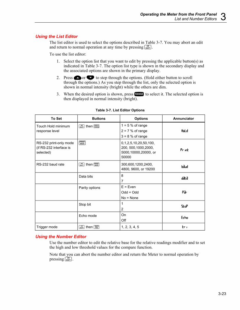
Operating the Meter from the Front Panel List and Number Editors 3
3-23
Using the List Editor The list editor is used to select the options described in Table 3-7. You may abort an edit and return to normal operation at any time by pressing Q. To use the list editor:
1. Select the option list that you want to edit by pressing the applicable button(s) as indicated in Table 3-7. The option list type is shown in the secondary display and the associated options are shown in the primary display.
2. Press Uor V to step through the options. (Hold either button to scroll through the options.) As you step through the list, only the selected option is shown in normal intensity (bright) while the others are dim.
3. When the desired option is shown, press R to select it. The selected option is then displayed in normal intensity (bright).
Table 3-7. List Editor Options
To Set Buttons Options Annunciator
Touch Hold minimum response level
Q then I 1 = 5 % of range 2 = 7 % of range 3 = 8 % of range
HoLd
RS-232 print-only mode (if RS-232 interface is selected)
K 0,1,2,5,10,20,50,100, 200, 500,1000,2000, 5000,10000,20000, or 50000
RS-232 baud rate Q then K 300,600,1200,2400, 4800, 9600, or 19200
baud
Data bits 8 7
data
Parity options E = Even Odd = Odd No = None
Par
Stop bit 1 2
StoP
Echo mode On Off
Echo
Trigger mode Q then J 1, 2, 3, 4, 5 tri
Using the Number Editor Use the number editor to edit the relative base for the relative readings modifier and to set the high and low threshold values for the compare function. Note that you can abort the number editor and return the Meter to normal operation by pressing Q.

DMM4020 Users Manual
3-24
To use the number editor: 1. Select the number to be edited by pressing the applicable buttons as shown in
Table 3-8. The last number entered or value measured is displayed with the leftmost digit bright and the remaining digits dim. (If the number is negative, the minus sign is bright.) Related annunciators are displayed.
Table 3-8. Number Editor Options
Buttons Number Editor Invoked for
Q then V Low threshold limit for compare mode
Q then U High threshold limit for compare mode
Q then T Relative base for relative readings modifier
2. Press U or V to increment or decrement the highlighted digit to the desired
number (from 0 to 9). When the digit is set to the desired number, press S1 through S6 to select the next digit to edit. S1 corresponds to the left-most digit and S6 corresponds to the right-most digit. Repeat this step until you have set all the digits to their desired values.
3. When the value has been set, press C to toggle the sign between positive and negative. If the sign is positive, the negative sign (–) is off. If the sign is negative, the negative sign (–) is on.
4. For Low/High threshold, press R to select the desired range for threshold values. The range goes one step up by pressing R once. If the range reaches the top range, the next press wraps back to range 1 and the value will be cleared.
5. When you are finished editing the number, press and hold R for 2 seconds to store the value.
Function Keys S1 – S6 Function keys a through f allow you to save and recall up to six measurement configurations. This helps speed the process of setting up the Meter, and is particularly useful if you repeatedly need the same configurations. To save the present configuration, press Q and then press the function key to which you want to store the configuration. To recall a configuration, press the applicable function key. A beep sounds when the configuration is ready for use, and Setup 8 indicates the number of the latest stored configuration. When a configuration is stored, it includes the following:
• Measurement function and initial range on primary display • Measurement function on secondary display • Range mode on primary display (manual or autorange) • Measurement rate (slow, medium, fast) • Dual display status (active or inactive) • Any combination of selected function modifiers

Operating the Meter from the Front Panel Power-Up Configuration 3
3-25
• Touch Hold level (1, 2, 3, 4) • Last recorded minimum and maximum values for MINMAX modifier • Last recorded relative base • Relative base shown in secondary display (enabled or disabled) • Last HI-LO settings in compare mode • Trigger mode (1, 2, 3, 4, 5) • Echo setting (on or off) • dB and dB reference • RS-232 settings • PRINT mode • Data format (with or without UNIT) sending through the RS-232
Power-Up Configuration When the Meter is turned on and the power-up sequence is complete, the Meter defaults to the power-up configuration listed in Table 3-9. The RS-232 baud rate, parity, and echo mode are not changed when power is cycled off and on. These parameters remain as set until changed by the user.
Table 3-9. Factory Power-Up Configuration
Parameter Configuration
Function setting DC volts
Range mode Autorange
Reading rate Slow (2.5 readings/second)
Touch Hold sensitivity level 1 (5 % of reading)
High/low values for Compare mode (COMP) 0
Minimum and maximum values in MIN MAX modifier 0
Relative base 0
Relative base in secondary display Disabled
Trigger type 1 (Internal)
Trigger type 0
Calibration Refer to the DMM4020 Technical Reference for instructions on calibrating the Meter.

DMM4020 Users Manual
3-26

4-1
Chapter 4 Operating the Meter Using the Computer
Interface
Title Page
Introduction........................................................................................................4-3
Local and Remote Operations .......................................................................4-3 Computer Interfaces ......................................................................................4-3
Preparing the Meter for Operations via the RS-232 Interface ...........................4-3 Setting Communication Parameters (RS-232) ..............................................4-3 RS-232 Print-Only Mode ..............................................................................4-4 Cabling the Meter to a Host or Printer (RS-232)...........................................4-5 Character Echoing and Deletion....................................................................4-6 Device Clear Using ^C (CNTRL C)..............................................................4-6 RS-232 Prompts.............................................................................................4-6
Getting Started with an Installation Test ...........................................................4-6 Installation Test for RS-232 Operation .........................................................4-6 If Test Fails....................................................................................................4-7
How the Meter Processes Input .........................................................................4-7 Input Strings ..................................................................................................4-7 Input Terminators ..........................................................................................4-7 Sending Numeric Values to the Meter ..........................................................4-8 Sending Command Strings to the Meter........................................................4-8
How the Meter Processes Output.......................................................................4-8 Triggering Output ..............................................................................................4-9
External Triggering from the Front Panel .....................................................4-9 Setting the Trigger Type Configuration ........................................................4-10 External Trigger via the Computer Interface.................................................4-10
Status Registers..................................................................................................4-11 Event Status and Event Status Enable Registers ...........................................4-12 Status Byte Register ......................................................................................4-14 Reading the Status Byte Register ..................................................................4-15
Computer Interface Command Set.....................................................................4-15 Common Commands .....................................................................................4-16 Function Commands and Queries..................................................................4-17 Function Modifier Commands and Queries ..................................................4-19 Range and Measurement Rate Commands and Queries................................4-21

DMM4020 Users Manual
4-2
Measurement Queries ....................................................................................4-23 Compare Commands and Queries .................................................................4-24 Trigger Configuration Commands.................................................................4-24 Miscellaneous Commands and Queries.........................................................4-25 RS-232 Remote / Local Configurations ........................................................4-26 RS-232 Save / Recall System Configurations ...............................................4-26
Sample Program Using the RS-232 Computer Interface ...................................4-26
Operating the Meter Using the Computer Interface Introduction 4
4-3
Introduction This chapter describes how to set up, configure and operate the Meter via the RS-232 computer interface on the Meter’s rear panel. The Meter can be operated from a host (a terminal, controller, PC, or computer) by sending commands to the Meter through its computer interface. An annotated sample program illustrating the use of the RS-232 computer interface is provided at the end of this chapter. Refer to Chapter 3 for complete descriptions of all Meter functions and features. This chapter assumes that you are familiar with the basics of data communication and RS-232 interface.
Local and Remote Operations When the Meter is operated from a host, it is said to be operated remotely. When the Meter is operated from its front panel, it is said to be operated locally. Most operations that can be performed locally can also be performed remotely using the computer interface. Some operations, like setting communications parameters for the RS-232 interface operations, can only be performed from the front panel.
Computer Interfaces The Meter comes equipped with an RS-232 (serial) interface. Using the interface turns the Meter into a fully programmable instrument that can be integrated into an automated instrumentation system.
Preparing the Meter for Operations via the RS-232 Interface The RS-232 interface allows ASCII asynchronous serial communication between the Meter and a host, serial printer or terminal.
Setting Communication Parameters (RS-232) Table 4-1 provides the RS-232 communication parameters factory settings. Setting RS-232 communication parameters is only performed through the front panel. In order for the Meter and host to communicate via the RS-232 interface, the communication parameters of the Meter must match those of the host. If the communications parameters of the host and Meter do not match, set the appropriate baud rate and parity parameters as follows:
1. Press P to turn the Meter on. 2. Press Q then K. The baud rate currently selected is shown in the primary
display and baud is shown in the secondary display. 3. Press U or V to scroll to the desired baud, and then press R to set the
RS-232 baud rate. 4. Press U or V to scroll to the desired data bit (7 or 8) selection, then press R to set parity. Echo appears on the secondary display, and 0n or 0FF appears on the primary display.
5. To select an Echo mode, press U or V to select On or OFF, and then press R to set the selected Echo state. When Echo is on, each command sent to the Meter over the RS-232 interface is echoed to the host's display screen. When Echo is off, commands are not echoed.
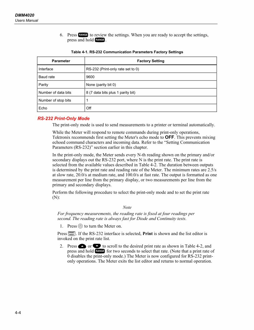
DMM4020 Users Manual
4-4
6. Press R to review the settings. When you are ready to accept the settings, press and hold R.
Table 4-1. RS-232 Communication Parameters Factory Settings
Parameter Factory Setting
Interface RS-232 (Print-only rate set to 0)
Baud rate 9600
Parity None (parity bit 0)
Number of data bits 8 (7 data bits plus 1 parity bit)
Number of stop bits 1
Echo Off
RS-232 Print-Only Mode The print-only mode is used to send measurements to a printer or terminal automatically. While the Meter will respond to remote commands during print-only operations, Tektronix recommends first setting the Meter's echo mode to OFF. This prevents mixing echoed command characters and incoming data. Refer to the “Setting Communication Parameters (RS-232)” section earlier in this chapter. In the print-only mode, the Meter sends every N-th reading shown on the primary and/or secondary displays out the RS-232 port, where N is the print rate. The print rate is selected from the available values described in Table 4-2. The duration between outputs is determined by the print rate and reading rate of the Meter. The minimum rates are 2.5/s at slow rate, 20.0/s at medium rate, and 100.0/s at fast rate. The output is formatted as one measurement per line from the primary display, or two measurements per line from the primary and secondary displays. Perform the following procedure to select the print-only mode and to set the print rate (N):
Note For frequency measurements, the reading rate is fixed at four readings per second. The reading rate is always fast for Diode and Continuity tests.
1. Press P to turn the Meter on. Press K. If the RS-232 interface is selected, Print is shown and the list editor is invoked on the print rate list.
2. Press U or V to scroll to the desired print rate as shown in Table 4-2, and press and hold R for two seconds to select that rate. (Note that a print rate of 0 disables the print-only mode.) The Meter is now configured for RS-232 print-only operations. The Meter exits the list editor and returns to normal operation.

Operating the Meter Using the Computer Interface Preparing the Meter for Operations via the RS-232 Interface 4
4-5
Table 4-2. Print Rates in RS-232 Print-Only Mode
Seconds between Outputs Minutes between Outputs Hours between Outputs Rate (N) Slow Medium Fast Slow Medium Fast Slow Medium Fast
1 0.4 0.05 0.01 0.01
2 0.8 0.1 0.02 0.01
5 2.0 0.25 0.05 0.03
10 4.0 0.5 0.1 0.07 0.01
20 8.0 1.0 0.2 0.13 0.02
50 20.0 2.5 0.5 0.33 0.04 0.01 0.01
100 40.0 5.0 1.0 0.67 0.08 0.02 0.01
200 80.0 10.0 2.0 1.33 0.17 0.03 0.02
500 200.0 25.0 5.0 3.33 0.42 0.08 0.06 0.01
1000 400.0 50.0 10.0 6.67 0.83 0.17 0.11 0.01
2000 800.0 100.0 20.0 13.33 1.67 0.33 0.22 0.03 0.01
5000 2000.0 250.0 50.0 33.33 4.17 0.83 0.56 0.07 0.01
10000 4000.0 500.0 100.0 66.67 8.33 1.67 1.11 0.14 0.03
20000 8000.0 1000.0 200.0 133.33 16.67 3.33 2.22 0.28 0.06
50000 20000.0 2500.0 500.0 333.33 41.67 8.33 5.56 0.69 0.14
Cabling the Meter to a Host or Printer (RS-232) The Meter communicates with a host through a DB-9 interface connector on the rear panel of the Meter. A connector pinout for the RS-232 interface is provided on the rear of the Meter.
Note When connecting the Meter to the host or terminal, use a cable appropriate to your application. It is recommended that you use a cable that is less than 50 feet long (1 meters), as this will help prevent performance degradation. Longer cables can be used if the load capacitance at the interface point (including signal terminator) is less than 2500 pf.
To connect the Meter to a personal computer (with DB-9 connector), use a modem cable. To connect the Meter to a specific brand of RS-232 printer, use the cable that would be used to connect that printer to an RS-232 port on a personal computer with a DB-9 connector.

DMM4020 Users Manual
4-6
Character Echoing and Deletion When the Meter is operated via the RS-232 interface, you can control whether characters are echoed to the host's display screen. When Echo is on, characters sent to the Meter are echoed on the host's display screen and prompts are returned. When Echo is off, characters are not echoed, and prompts are not returned. To set the Echo parameter, refer to the “Setting Communication Parameters (RS-232)” section earlier in this chapter. If you send a character to the Meter over the RS-232 interface directly from a keyboard, pressing the <BACKSPACE> key deletes the previous character. A backspace is echoed to the display screen if Echo is on.
Device Clear Using ^C (CNTRL C) ^C (CNTRL C) causes “=>” followed by a carriage return and line feed to be output.
RS-232 Prompts When the host sends a command to the Meter over the RS-232 interface, the Meter parses the command, executes it, returns a response (if appropriate), and then sends one of the following prompts:
=> No errors detected. Command was successfully parsed and executed. The interface is ready for another command.
?> Command error detected. Command was not executed because it was not understood. For example, the Meter received an input string that contained a syntax error.
!> Execution error or device-dependent error detected. Command was understood, but not executed. For example, user attempted to use FREQ to perform a VDC measurement.
Getting Started with an Installation Test After the Meter is cabled to a host per “Cabling the Meter to a Host or Printer (RS-232)” and is prepared to communicate with the host via the RS-232 interface, test the system as follows to verify that it is operational.
Installation Test for RS-232 Operation This procedure confirms that the Meter is properly set up and cabled for remote operations:
1. Press P to turn the Meter on. 2. Verify that the computer interface parameters (baud, parity, etc.) are set
correctly. 3. Turn the host on. 4. Type *IDN? and press Enter. 5. Verify that the Meter sends the following response:
TEKTRONIX, DMM4020, nnnnnnn, n.n Dn.n Where nnnnnnn is the Meter’s serial number; n.n is the main software version; and Dn.n is the display’s software version.
Operating the Meter Using the Computer Interface How the Meter Processes Input 4
4-7
6. If the Meter does not respond as indicated, refer to the “If Test Fails” section.
If Test Fails If the Meter does not respond as indicated in the “Installation Test for RS-232 Operation” section, perform the following:
1. Ensure all cables are properly connected. See the “Cabling the Meter to a Host or Printer (RS-232)” section earlier in this chapter.
2. Ensure that the communication parameters (baud rate, parity, etc.) on the Meter and host are identical. See the “Setting Communication Parameters (RS-232)” section earlier in this chapter.
How the Meter Processes Input The following sections describe how the Meter processes input received from a host or stand-alone terminal.
Note In this Chapter, “input” means a string sent to the Meter from a host, and “output” means a string sent to the host from the Meter through the computer interface.
Input Strings The Meter processes and executes valid input strings sent by the host. A valid input string is one or more syntactically correct commands followed by an input terminator. When the Meter receives input, it stores it in a 50-byte input buffer.
Note Input strings received over the RS-232 interface are not executed or checked for proper syntax until an input terminator is received or the input buffer becomes full.
The Meter accepts alphabetic characters in uppercase and lowercase. If a command cannot be understood, the command and the rest of the command line are ignored.
Input Terminators When the Meter receives an input terminator, it executes commands on a first-in first-out basis as entered since the last terminator was received. As input characters are processed and executed, space is made available in the input buffer for new characters. In RS-232 applications, if a communication error (parity, framing, overrun) is detected, a device-dependent error is generated and the input string is discarded. If the Meter's input buffer becomes full when it is used with the RS-232 interface, a device-dependent error is generated (see “Event Status and Event Status Enable Register”) and the input string is discarded. Valid terminators for the RS-232 interface are:
• CR (Carriage Return) • LF (Line Feed • CR LF (Carriage Return/ Line Feed)
DMM4020 Users Manual
4-8
In some instances, a terminator is automatically transmitted at the end of the host’s output string (the Meter's input string).
Sending Numeric Values to the Meter Numeric values can be sent to the Meter as integers, real numbers, or real numbers with exponents, as shown in the following examples: +12345689 Sends the signed integer “12345689” -1.2345E2 Sends “-1.2345E2” or “-123.45”
Sending Command Strings to the Meter Observe the following rules when you construct strings to be sent to the Meter over the computer interface: • Rule 1: Read meter's output buffer once for each query command.
The Meter’s output buffer is cleared after it has been read. This prevents previously read data from being read a second time by mistake. If you attempt to read the Meter’s output buffer twice without an intervening query, the Meter will not respond to the second read.
• Rule 2: Read query responses before sending another command string. Output data remains available in the output buffer until the host reads it or until the next command string is received by the Meter. This means the host must read the Meter’s output buffer before the next command string is sent to the Meter.
• Rule 3: The meter executes each command completely in the order received before moving on to the next command. If an input string contains a trigger, enter the commands in the following order: 1. Commands to configure the Meter (if any) 2. The trigger command 3. Commands to read the result of a triggered measurement (VAL?), or to
reconfigure the instrument (if any) 4. The terminator
Note If MEAS?, MEAS1? or MEAS2? is used, the command should follow Configure, Trigger.
How the Meter Processes Output The following paragraphs describe how the Meter processes output. The Meter outputs an alphanumeric string in response to a query command from the host. (Query commands end with “?”.) Output strings for RS-232 applications are terminated with a Carriage Return and Line Feed (<CR><LF>). After sending the Meter a command via the RS-232 interface, wait for the Meter to return a prompt before sending another command. Failure to do so causes a device-dependent command error, and the second string is discarded. Numeric output from the Meter is shown in the following examples: +1.2345E+0(format 1) Measured value of 1.2345
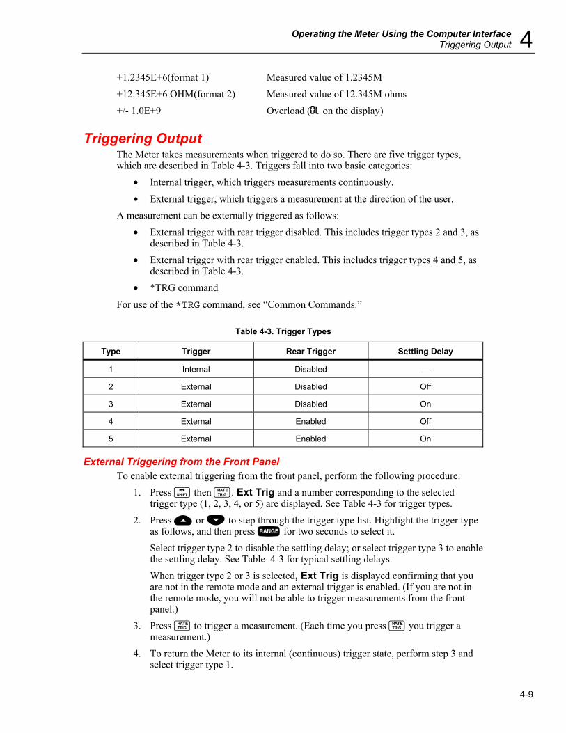
Operating the Meter Using the Computer Interface Triggering Output 4
4-9
+1.2345E+6(format 1) Measured value of 1.2345M +12.345E+6 OHM(format 2) Measured value of 12.345M ohms +/- 1.0E+9 Overload (0L on the display)
Triggering Output The Meter takes measurements when triggered to do so. There are five trigger types, which are described in Table 4-3. Triggers fall into two basic categories:
• Internal trigger, which triggers measurements continuously. • External trigger, which triggers a measurement at the direction of the user.
A measurement can be externally triggered as follows: • External trigger with rear trigger disabled. This includes trigger types 2 and 3, as
described in Table 4-3. • External trigger with rear trigger enabled. This includes trigger types 4 and 5, as
described in Table 4-3. • *TRG command
For use of the *TRG command, see “Common Commands.”
Table 4-3. Trigger Types
Type Trigger Rear Trigger Settling Delay
1 Internal Disabled —
2 External Disabled Off
3 External Disabled On
4 External Enabled Off
5 External Enabled On
External Triggering from the Front Panel To enable external triggering from the front panel, perform the following procedure:
1. Press Q then J. Ext Trig and a number corresponding to the selected trigger type (1, 2, 3, 4, or 5) are displayed. See Table 4-3 for trigger types.
2. Press U or V to step through the trigger type list. Highlight the trigger type as follows, and then press R for two seconds to select it. Select trigger type 2 to disable the settling delay; or select trigger type 3 to enable the settling delay. See Table 4-3 for typical settling delays. When trigger type 2 or 3 is selected, Ext Trig is displayed confirming that you are not in the remote mode and an external trigger is enabled. (If you are not in the remote mode, you will not be able to trigger measurements from the front panel.)
3. Press J to trigger a measurement. (Each time you press J you trigger a measurement.)
4. To return the Meter to its internal (continuous) trigger state, perform step 3 and select trigger type 1.

DMM4020 Users Manual
4-10
If you enter the remote mode with trigger type 4 or 5 selected, the Meter remains in its external trigger state; however, because the Meter is in the remote mode, you will only be able to trigger measurements with rear trigger types 4 and 5. To exit remote mode, perform steps 1 and 2 and select trigger type 2 or 3 (as applicable).
Note In external trigger mode (mode 2 to mode 5), *TRG command is always available.
Setting the Trigger Type Configuration To set the trigger type configuration using the computer interface, enter the command TRIGGER <type> (where <type> is the trigger type) and press Enter. See Table 4-3 for trigger types. Select trigger type 3 or 5 to enable the settling delay if the input signal is not stable before a measurement is triggered. Typical settling delays are provided in Table 4-3. RS-232 reading transfer rates are provided in Table 4-4.
Table 4-4. RS-232 Reading Transfer Rates
Readings per Second Rate
Internal Trigger Operation (Trigger 1) External Trigger Operation (Trigger 4)
Slow 2.5[1] 2.5[2]
Medium 20[1] 20[2]
Fast 100[1] 100[2]
[1] Depends on A/D trigger speed.
[2] Depends on how fast the trigger signal is transmitted.
External Trigger via the Computer Interface To trigger a measurement using the RS-232 computer interface, enter the command *TRG and press Enter. See the “Common Commands” section later in this chapter for use of *TRG command. To trigger a measurement using pin 9 of the RS-232 interface, see Figure 4-1.
+5 V Out (Pin 1)
Trig In (Pin 9)
eue24.eps
Figure 4-1. External Trigger Using Pin 9 of RS-232 Interface
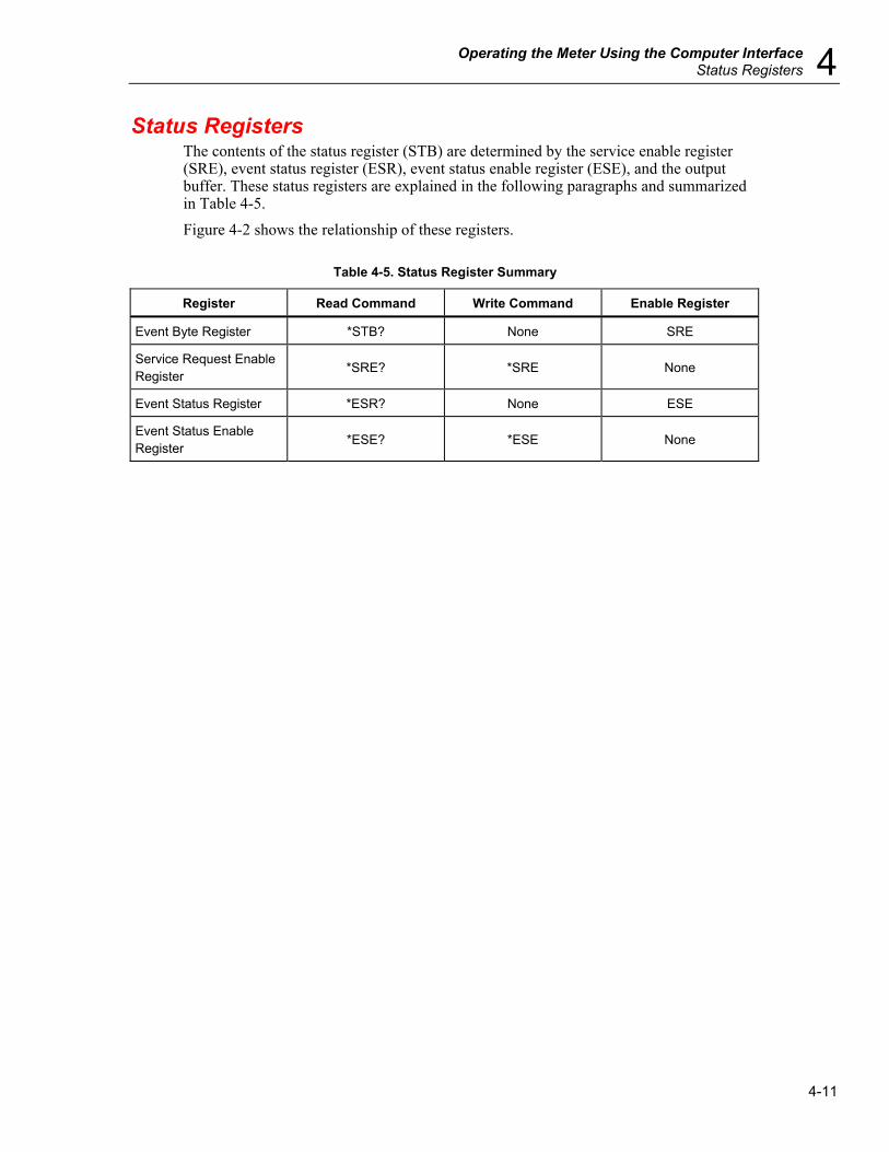
Operating the Meter Using the Computer Interface Status Registers 4
4-11
Status Registers The contents of the status register (STB) are determined by the service enable register (SRE), event status register (ESR), event status enable register (ESE), and the output buffer. These status registers are explained in the following paragraphs and summarized in Table 4-5. Figure 4-2 shows the relationship of these registers.
Table 4-5. Status Register Summary
Register Read Command Write Command Enable Register
Event Byte Register *STB? None SRE
Service Request Enable Register
*SRE? *SRE None
Event Status Register *ESR? None ESE
Event Status Enable Register
*ESE? *ESE None
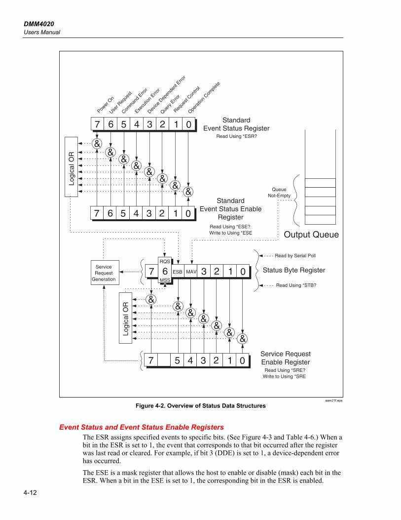
DMM4020 Users Manual
4-12
01234567
01234567
&
&&
&&
&&
&Logi
cal O
R
StandardEvent Status Register
Read Using *ESR?
StandardEvent Status Enable
RegisterRead Using *ESE? Write to Using *ESE
Power
On
User R
eque
st
Comm
and
Error
Execu
tion
Error
Device
Dep
ende
nt E
rror
Query
Erro
r
Reque
st Con
trol
Opera
tion
Comple
te
01237
0123457
&&
&&
&&
&
Logi
cal O
R
Status Byte Register
Service RequestEnable Register
MSS
6RQS
ESB MAV
Read Using *SRE?Write to Using *SRE
Output Queue
QueueNot-Empty
Read by Serial Poll
Read Using *STB?
ServiceRequest
Generation
aam21f.eps
Figure 4-2. Overview of Status Data Structures
Event Status and Event Status Enable Registers The ESR assigns specified events to specific bits. (See Figure 4-3 and Table 4-6.) When a bit in the ESR is set to 1, the event that corresponds to that bit occurred after the register was last read or cleared. For example, if bit 3 (DDE) is set to 1, a device-dependent error has occurred. The ESE is a mask register that allows the host to enable or disable (mask) each bit in the ESR. When a bit in the ESE is set to 1, the corresponding bit in the ESR is enabled.
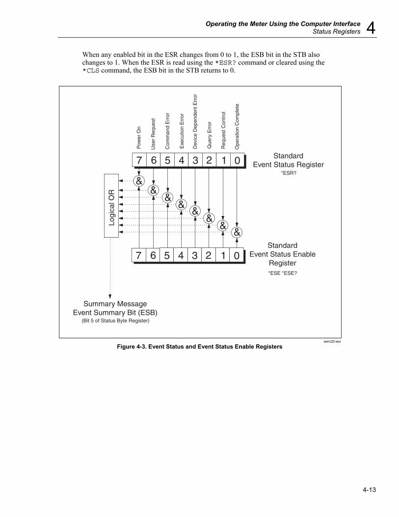
Operating the Meter Using the Computer Interface Status Registers 4
4-13
When any enabled bit in the ESR changes from 0 to 1, the ESB bit in the STB also changes to 1. When the ESR is read using the *ESR? command or cleared using the *CLS command, the ESB bit in the STB returns to 0.
01234567
01234567
&
&&
&&
&&
&Logi
cal O
R
StandardEvent Status Register
*ESR?
StandardEvent Status Enable
Register*ESE *ESE?
Pow
er O
n
Use
r R
eque
st
Com
man
d E
rror
Exe
cutio
n E
rror
Dev
ice
Dep
ende
nt E
rror
Que
ry E
rror
Req
uest
Con
trol
Ope
ratio
n C
ompl
ete
Summary MessageEvent Summary Bit (ESB)
(Bit 5 of Status Byte Register)
aam22f.eps
Figure 4-3. Event Status and Event Status Enable Registers

DMM4020 Users Manual
4-14
Table 4-6. Description of Bits in ESR and ESE
Bit No. Name Condition
0 Operation Complete (OPC) All commands before receipt of an *OPC command have been executed. Interface is ready to accept another message.
1 Not used Always set to 0.
2 Query Error (QYE) Attempted to read data from the Meter's output buffer when no output was present or pending.
Or received a new command line before a previous query was read.
Or input and output buffers were full.
3 Device-Dependent Error (DDE) Incorrect input during calibration.
Or RS-232 input buffer overflow.
4 Execution Error (EXE) Command was understood but could not be executed. This can result from a command that contained an inappropriate parameter.
5 Command Error (CME) Command was not executed because it was not understood. This can result from a command that contained a syntax error.
6 Not used Always set to 0.
7 Power On Power was cycled off and on since the last time the ESR was read or cleared.
Status Byte Register The STB is a binary-encoded register that contains eight bits. Note that the SRE uses bits 1 through 5 and 7 to set bit 6, the Master Summary Status (MSS) bit, as enabled by the SRE. The eight STB bits are described in Table 4-7, and are read using the *STB? command.
Table 4-7. Description of Bits in the Status Byte Register (STB)
Bit No. Name Condition
0 Not used Always set to 0.
1 Not used Always set to 0.
2 Not used Always set to 0.
3 Not used Always set to 0.
4 Message Available (MAV) Data is available in output buffer. Bit set to 1 when response to query placed in output buffer. Bit cleared (set to 0) when output terminator sent to host.
5 Event Status (ESB) One or more of enabled events in the Event Status Register have occurred. To determine which events have occurred, send command *ERR? to read the Event Status Register.

Operating the Meter Using the Computer Interface Computer Interface Command Set 4
4-15
Table 4-7. Description of Bits in the Status Byte Register (STB) (cont.)
Bit No. Name Condition
6 Master Summary Status (MSS) [1] Set to 1 if any enabled bit in the STB (MSS) register is set to 1; otherwise set to 0. To determine the status of MSS bit, send STB? query command.
Request Service (RQS) is set to 1 if service requested from front panel or MSS is set to 1. Status of bit is returned by serial poll, which clears RQS.
7 Not used Always set to 0.
[1] As read by *STB? Command. If the STB is read by a serial poll, bit 6 is returned as RQS.
Reading the Status Byte Register The host reads the STB by taking a serial poll or sending the Meter a *STB? query. (The value of the status byte is not affected by the STB? query.) When the STB is read, an integer is returned. This integer is the decimal equivalent of an 8-bit binary number. For example, 48 is the decimal equivalent of the binary 00110000, which means that bit 4 (MAV) and bit 5 (ESB) are set to 1. If the status byte is read with an *STB? query, bit 6 is returned as Master Summary Status (MSS). See the following example: *STB? reads the STB. If 32 is returned, it is converted to its binary equivalent of 00100000, which indicates that bit 5 (ESB) is set to 1. To determine the event status, you would read the ESB in the same manner, using the *ESR? command.
Computer Interface Command Set The remainder of this chapter describes the RS-232 computer interface commands. Commands are grouped by related function and are listed in the tables that follow. Parameters that must be supplied by the user or strings returned by the Meter are enclosed in angle brackets (for example, <value>).
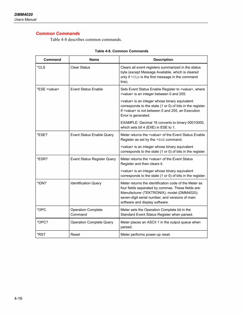
DMM4020 Users Manual
4-16
Common Commands Table 4-8 describes common commands.
Table 4-8. Common Commands
Command Name Description
*CLS Clear Status Clears all event registers summarized in the status byte (except Message Available, which is cleared only if *CLS is the first message in the command line).
*ESE <value> Event Status Enable Sets Event Status Enable Register to <value>, where <value> is an integer between 0 and 255.
<value> is an integer whose binary equivalent corresponds to the state (1 or 0) of bits in the register. If <value> is not between 0 and 255, an Execution Error is generated.
EXAMPLE: Decimal 16 converts to binary 00010000, which sets bit 4 (EXE) in ESE to 1.
*ESE? Event Status Enable Query Meter returns the <value> of the Event Status Enable Register as set by the *ESE command.
<value> is an integer whose binary equivalent corresponds to the state (1 or 0) of bits in the register.
*ESR? Event Status Register Query Meter returns the <value> of the Event Status Register and then clears it.
<value> is an integer whose binary equivalent corresponds to the state (1 or 0) of bits in the register.
*IDN? Identification Query Meter returns the identification code of the Meter as four fields separated by commas. These fields are: Manufacturer (TEKTRONIX); model (DMM4020); seven-digit serial number; and versions of main software and display software.
*OPC Operation Complete Command
Meter sets the Operation Complete bit in the Standard Event Status Register when parsed.
*OPC? Operation Complete Query Meter places an ASCII 1 in the output queue when parsed.
*RST Reset Meter performs power-up reset.

Operating the Meter Using the Computer Interface Computer Interface Command Set 4
4-17
Table 4-8. Common Commands (cont.)
Command Name Description
*SRE Service Request Enable Sets the Service Request Enable Register to <value>, where <value> is an integer between 0 and 255. The value of bit 6 is ignored because the Service Request Enable Register does not use it.
<value> is an integer whose binary equivalent corresponds to the state (1 or 0) of bits in the register. If <value> is not between 0 and 255, an Execution Error is generated.
*SRE? Service Request Enable Query
Meter returns the <value> of the Service Request Enable Register (with bit 6 set to 0).
<value> is an integer whose binary equivalent corresponds to the state (1 or 0) of bits in the register.
*STB? Read Status Byte Meter returns the <value> of the Status Byte with bit 6 as the Master Summary bit.
<value> is an integer whose binary equivalent corresponds to the state (1 or 0) of bits in the register.
*TRG Trigger Causes the Meter to trigger a measurement when parsed.
*TST Self test query Always returns zero.
*WAI Wait-to-Continue Do nothing.
Function Commands and Queries Table 4-9 describes function commands and queries. Refer to Chapter 3 for detailed descriptions of each function.
Table 4-9. Function Commands and Queries
Commands
Primary Display Secondary Display Function
AAC AAC2 AC current
AACDC [1] (Not applicable) AC plus DC rms current
ADC ADC2 DC current
(Not applicable) CLR2 Clears measurement (if shown)
CONT (Not applicable) Continuity test
DIODE (Not applicable) Diode test
FREQ FREQ2 Frequency

DMM4020 Users Manual
4-18
Table 4-9. Function Commands and Queries (cont.)
Commands
Primary Display Secondary Display Function
FUNC1? (Not applicable) Meter returns function selected as command mnemonic. For example, if frequency is selected, FUNC1? returns FREQ.
(Not applicable) FUNC2? Meter returns function selected as command mnemonic. For example, if frequency is selected, FUNC2? returns FREQ
If secondary display is not in use, an Execution Error is generated.
OHMS OHMS2 Resistance
WIRE2, WIRE4 (Not applicable) Only available in OHMS function. Used to switch between 2-wire and 4-wire measurement.
VAC VAC2 AC volts
VACDC [1] (Not applicable) AC plus dc rms volts
VDC VDC2 DC volts
[1] When AACDC or VACDC is selected, no function can be selected for the secondary display. An execution error is generated if attempted.
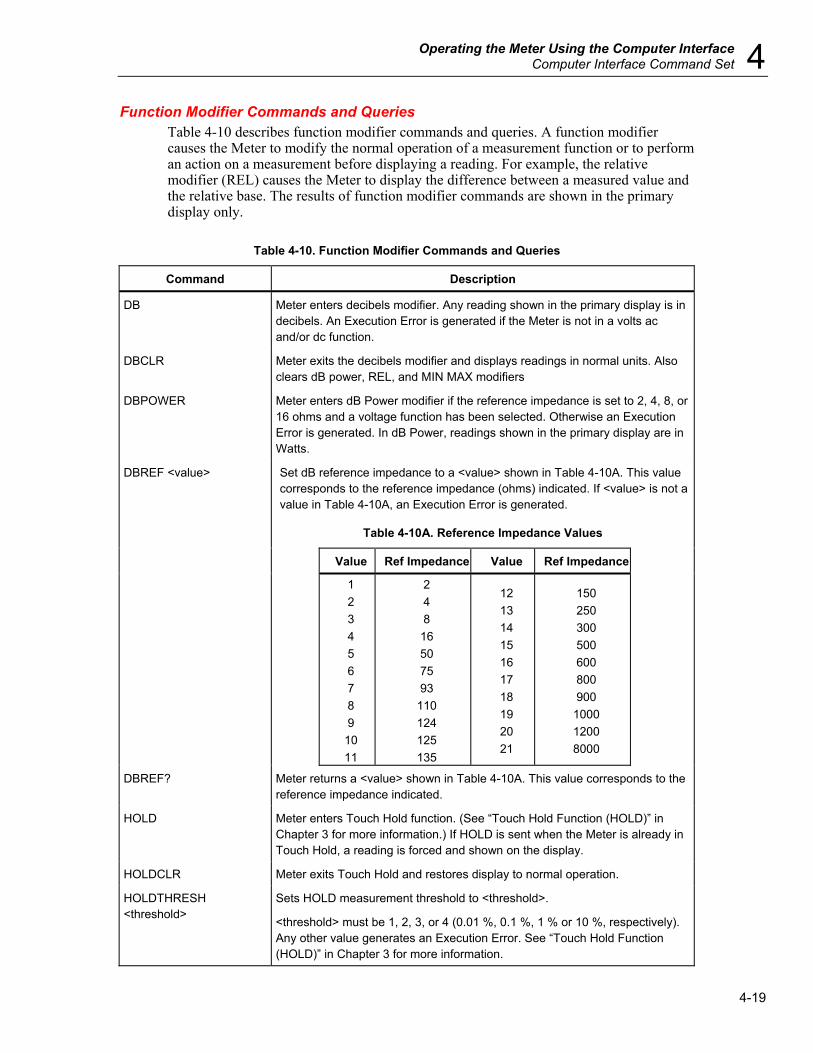
Operating the Meter Using the Computer Interface Computer Interface Command Set 4
4-19
Function Modifier Commands and Queries Table 4-10 describes function modifier commands and queries. A function modifier causes the Meter to modify the normal operation of a measurement function or to perform an action on a measurement before displaying a reading. For example, the relative modifier (REL) causes the Meter to display the difference between a measured value and the relative base. The results of function modifier commands are shown in the primary display only.
Table 4-10. Function Modifier Commands and Queries
Command Description
DB Meter enters decibels modifier. Any reading shown in the primary display is in decibels. An Execution Error is generated if the Meter is not in a volts ac and/or dc function.
DBCLR Meter exits the decibels modifier and displays readings in normal units. Also clears dB power, REL, and MIN MAX modifiers
DBPOWER Meter enters dB Power modifier if the reference impedance is set to 2, 4, 8, or 16 ohms and a voltage function has been selected. Otherwise an Execution Error is generated. In dB Power, readings shown in the primary display are in Watts.
Set dB reference impedance to a <value> shown in Table 4-10A. This value corresponds to the reference impedance (ohms) indicated. If <value> is not a value in Table 4-10A, an Execution Error is generated.
Table 4-10A. Reference Impedance Values
Value Ref Impedance Value Ref Impedance
DBREF <value>
1 2 3 4 5 6 7 8 9 10 11
2 4 8 16 50 75 93
110 124 125 135
12 13 14 15 16 17 18 19 20 21
150 250 300 500 600 800 900
1000 1200 8000
DBREF? Meter returns a <value> shown in Table 4-10A. This value corresponds to the reference impedance indicated.
HOLD Meter enters Touch Hold function. (See “Touch Hold Function (HOLD)” in Chapter 3 for more information.) If HOLD is sent when the Meter is already in Touch Hold, a reading is forced and shown on the display.
HOLDCLR Meter exits Touch Hold and restores display to normal operation.
HOLDTHRESH <threshold>
Sets HOLD measurement threshold to <threshold>.
<threshold> must be 1, 2, 3, or 4 (0.01 %, 0.1 %, 1 % or 10 %, respectively). Any other value generates an Execution Error. See “Touch Hold Function (HOLD)” in Chapter 3 for more information.

DMM4020 Users Manual
4-20
Table 4-10. Function Modifier Commands and Queries (cont.)
Command Description
HOLDTHRESH? Meter returns Touch Hold <threshold> (1, 2, 3, or 4). See “Touch Hold Function (HOLD)” in Chapter 3 for more information.
MAX Meter enters MAX modifier with present reading as maximum value. If already in MAX modifier, Meter displays maximum value. In MAX modifier, autoranging is disabled. See “Minimum / Maximum Modifier (MIN MAX)” in Chapter 3 for more information.
MAXSET <numeric value> Meter enters MAX modifier with <numeric value> as the maximum value.
<numeric value> can be a signed integer, signed real number without exponent, or signed real number with exponent. Autoranging is disabled. See “Minimum / Maximum Modifier (MIN MAX)” in Chapter 3 for more information.
If <numeric value> exceeds the measurement range, an Execution Error is generated.
MIN Meter enters MIN modifier with present reading as minimum value. If already in MIN modifier, Meter displays minimum value. In MIN modifier, autoranging is disabled. See “Minimum / Maximum Modifier (MIN MAX)” in Chapter 3 for more information.
MINSET <numeric value> Meter enters MIN modifier with <numeric value> as the minimum value.
<numeric value> can be a signed integer, signed real number without exponent, or signed real number with exponent. Autoranging is disabled. See “Minimum / Maximum Modifier (MIN MAX)” in Chapter 3 for more information.
If <numeric value> exceeds the measurement range, an Execution Error is generated.
MNMX Meter enters MIN MAX modifier with present reading as minimum and maximum value. If already in MIN MAX modifier, Meter displays latest MIN or MAX value. In MIN MAX modifier, autoranging is disabled. See “Minimum / Maximum Modifier (MIN MAX)” in Chapter 3 for more information.
When the MIN MAX modifier is selected, you can toggle between displaying the minimum and maximum readings without losing the minimum and maximum values stored.
MNMXSET <numeric1, numeric2>
Meter enters MIN MAX modifier with <numeric1> as the maximum value and <numeric2> as the minimum value.
<numeric1> and <numeric2> can be signed integer, signed real number without exponent, or signed real number with exponent. Autoranging is disabled. See “Minimum / Maximum Modifier (MIN MAX)” in Chapter 3 for more information.
If <numeric1> or <numeric2> exceeds the measurement range, an Execution Error is generated.
MMCLR Meter exits the MN MX modifier. The stored minimum and maximum values are lost, and the Meter returns to the ranging mode and range selected prior to selecting MN MX modifier.

Operating the Meter Using the Computer Interface Computer Interface Command Set 4
4-21
Table 4-10. Function Modifier Commands and Queries (cont.)
Command Description
MOD? Meter returns a numeric value indicating modifiers in use, where 1 = MIN; 2 = MAX; 4 = HOLD; 8 = dB; 16 = dB Power; 32 = REL; and 64 = COMP.
If multiple modifiers are selected, the value returned is equal to the sum of the values of the selected modifiers. For example, if dB and REL are selected, 40 is returned.
REL Meter enters the relative readings modifier (REL) using the value shown on the primary display as the relative base. Autoranging is disabled. See “Relative Readings Modifier (REL)” in Chapter 3 for more information.
RELCLR Meter exits REL modifier and returns to the ranging mode and range selected prior to selecting REL.
RELSET <relative base> Meter enters REL modifier using <relative base> as the offset <relative base> value.
<relative base> can be a signed integer, signed real number without exponent, or signed real number with exponent. Autoranging is disabled.
If <relative base> exceeds the measurement range, an Execution Error is generated. See “Relative Readings Modifier (REL)” in Chapter 3 for more information.
RELSET? Meter returns <relative base>. If the relative modifier has not been selected, an Execution Error is generated.
Range and Measurement Rate Commands and Queries Table 4-11 describes range and measurement rate commands and queries. In autorange mode, the Meter automatically selects a range for each reading. In manual range mode, the user selects a fixed range.
Table 4-11. Range and Measurement Rate Commands and Queries
Command Description
AUTO Meter enters the autoranging mode on the primary display. If autorange mode cannot be selected (if REL, MIN MAX or diode/continuity test is selected), an Execution Error is generated.
AUTO? Meter returns 1 if it is in autorange or 0 if not in autorange.
FIXED Meter exits autoranging on the primary display and enters manual ranging. The present range becomes the selected range.

DMM4020 Users Manual
4-22
Table 4-11. Range and Measurement Rate Commands and Queries (cont.)
Command Description
RANGE <value range> Sets the primary display to <value range> where <value range> is the number in the Range Value column of Table 4-11A that corresponds with the applicable function ranges (voltage, ohms, current, etc.).
Table 4-11A. Ranges for Each Function
Range Value
Voltage Range
Ohms Range
AC Current
Freq. Range
DC Current
1 200 mV 200 e 20 mA 2 kHz 200 µA
2 2 V 2 ke 200 mA 20 kHz 2000 µA
3 20 V 20 ke 2 A 200 kHz 20 mA
4 200 V 200 ke 10 A 1000 kHz 200 mA
5 1000 V dc[1] 2 Me NA NA 2 A
6 NA 20 Me NA NA 10 A
7 NA 100 Me NA NA NA
[1] 1000 V dc, 750 V ac
RANGE1? Returns the range presently selected on the primary display.
RANGE2? Returns the range presently selected on the secondary display. If the secondary display is inactive, an Execution Error is generated.
RATE <speed> Sets the measurement rate to <speed> where <speed> is either S for slow (2.5 readings/second), M for medium (20 readings/second), or F for fast (100 readings/second).
S, M, and F can be entered as uppercase or lowercase. Any other entry for <speed> generates an Execution Error.
RATE? Returns <speed> as S for slow (2.5 readings/second), M for medium (20 readings/second), or F for fast (100 readings/second).
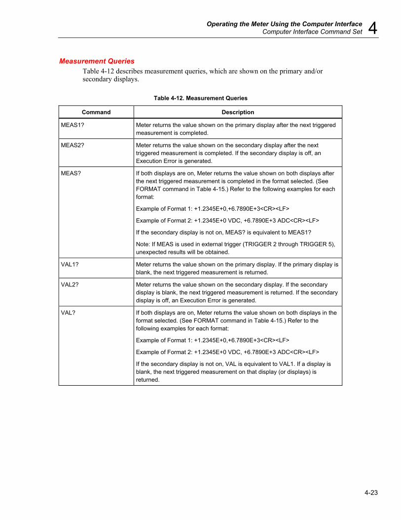
Operating the Meter Using the Computer Interface Computer Interface Command Set 4
4-23
Measurement Queries Table 4-12 describes measurement queries, which are shown on the primary and/or secondary displays.
Table 4-12. Measurement Queries
Command Description
MEAS1? Meter returns the value shown on the primary display after the next triggered measurement is completed.
MEAS2? Meter returns the value shown on the secondary display after the next triggered measurement is completed. If the secondary display is off, an Execution Error is generated.
MEAS? If both displays are on, Meter returns the value shown on both displays after the next triggered measurement is completed in the format selected. (See FORMAT command in Table 4-15.) Refer to the following examples for each format:
Example of Format 1: +1.2345E+0,+6.7890E+3<CR><LF>
Example of Format 2: +1.2345E+0 VDC, +6.7890E+3 ADC<CR><LF>
If the secondary display is not on, MEAS? is equivalent to MEAS1?
Note: If MEAS is used in external trigger (TRIGGER 2 through TRIGGER 5), unexpected results will be obtained.
VAL1? Meter returns the value shown on the primary display. If the primary display is blank, the next triggered measurement is returned.
VAL2? Meter returns the value shown on the secondary display. If the secondary display is blank, the next triggered measurement is returned. If the secondary display is off, an Execution Error is generated.
VAL? If both displays are on, Meter returns the value shown on both displays in the format selected. (See FORMAT command in Table 4-15.) Refer to the following examples for each format:
Example of Format 1: +1.2345E+0,+6.7890E+3<CR><LF>
Example of Format 2: +1.2345E+0 VDC, +6.7890E+3 ADC<CR><LF>
If the secondary display is not on, VAL is equivalent to VAL1. If a display is blank, the next triggered measurement on that display (or displays) is returned.

DMM4020 Users Manual
4-24
Compare Commands and Queries Table 4-13 describes the compare commands and queries. These commands cause the Meter to determine whether a measurement is higher than, lower than, or within a specified range. These commands correspond with C, U and V on the front panel.
Table 4-13. Compare Commands and Queries
Command Description
COMP Meter enters compare (COMP) function. Touch Hold is automatically turned on. (Touch Hold can be turned off with HOLDCLR command.)
COMP? Meter returns Hl if the last COMP measurement reading was above the upper limit of the compare range; LO if it was below the lower limit of the compare range; PASS if within compare range; or a dash (—) if a measurement has not completed.
COMPCLR Meter exits compare function (and Touch Hold if it is selected) and restores display to normal operation.
COMPHI <high value> Sets HI compare (COMP) value to <high value>.
<high value> can be a signed integer, signed real number without exponent, or signed real number with exponent.
COMPLO <low value> Sets LO compare (COMP) value to <low value>.
<low value> can be a signed integer, signed real number without exponent, or signed real number with exponent.
HOLDCLR Meter exits Touch Hold and restores display to normal operation, but does not exit the compare function.
Trigger Configuration Commands Table 4-14 describes the trigger configuration commands, which set and return the trigger configuration.
Table 4-14. Trigger Configuration Commands
Command Description
TRIGGER <type> Sets the trigger configuration to <type> where <type> is the number in the Type column of Table 4-3 that corresponds with the applicable trigger, rear trigger and setting delay. If the <type> entered is not between 1 and 5, an Execution Error is generated.
Select a trigger type with settling delay enabled (trigger type 3 or 5) when the input signal is not stable before a measurement is triggered. Typical settling delays are provided in Table 4-3.
TRIGGER? Returns the trigger type set by the TRIGGER command.
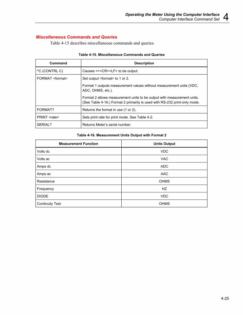
Operating the Meter Using the Computer Interface Computer Interface Command Set 4
4-25
Miscellaneous Commands and Queries Table 4-15 describes miscellaneous commands and queries.
Table 4-15. Miscellaneous Commands and Queries
Command Description
^C (CONTRL C) Causes =><CR><LF> to be output.
FORMAT <format> Set output <format> to 1 or 2.
Format 1 outputs measurement values without measurement units (VDC, ADC, OHMS, etc.).
Format 2 allows measurement units to be output with measurement units. (See Table 4-16.) Format 2 primarily is used with RS-232 print-only mode.
FORMAT? Returns the format in use (1 or 2).
PRINT <rate> Sets print rate for print mode. See Table 4-2.
SERIAL? Returns Meter’s serial number.
Table 4-16. Measurement Units Output with Format 2
Measurement Function Units Output
Volts dc VDC
Volts ac VAC
Amps dc ADC
Amps ac AAC
Resistance OHMS
Frequency HZ
DIODE VDC
Continuity Test OHMS

DMM4020 Users Manual
4-26
RS-232 Remote / Local Configurations Table 4-17 describes the RS-232 remote and local configuration commands, which are used with the RS-232 interface to set up the remote/local configuration of the Meter. These commands are valid only when the RS-232 interface is enabled.
Table 4-17. Remote/Local Configuration Commands
Command Description
REMS Puts the Meter into remote (REMS) state mode without front panel lockout. r is shown on the display.
RWLS Puts the Meter in remote with lockout state (RWLS) with front panel lockout. r and L are shown on the display. When in RWLS, all front panel buttons are disabled.
LOCS Puts the Meter is local state (LOCS) mode without lockout. All front panel buttons are enabled.
LWLS Puts the Meter in local with lockout state (LWLS) mode. All front panel buttons are disabled. L is shown on the display.
RS-232 Save / Recall System Configurations Table 4-18 describes RS-232 save/recall system configuration commands, which are used with the RS-232 interface to set up the remote/local configuration of the Meter.
Table 4-18. Save / Call System Configuration Commands
Command Description
Save <position> Saves the current running working status into <position>, where <position> is 1 through 6.
Call <position> Recalls the working status from <position>, where <position> is 1 through 6.
Sample Program Using the RS-232 Computer Interface Figure 4-4 is an annotated BASIC A program written for a PC that demonstrates how the Meter can be used with the RS-232 computer interface.
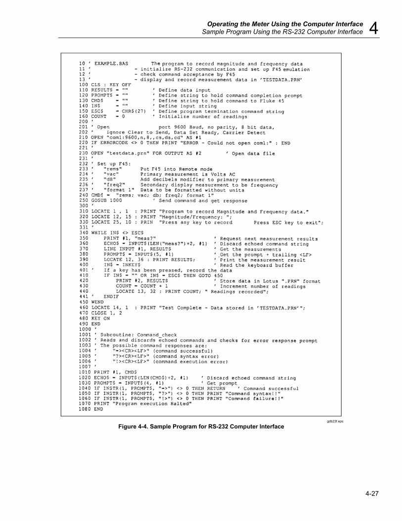
Operating the Meter Using the Computer Interface Sample Program Using the RS-232 Computer Interface 4
4-27
gdb23f.eps
Figure 4-4. Sample Program for RS-232 Computer Interface

DMM4020 Users Manual
4-28
Appendices
Appendix Title Page
A Applications ........................................................................................................ A-1 B 2X4 Test Leads ................................................................................................... B-1

A-1
Appendix A Applications
Introduction This chapter discusses some applications that will help you use the Meter effectively. These applications assume you are familiar with the basic operation of the Meter and have a basic understanding of electronics. A sophisticated understanding of electrical circuits is not necessary.
Using the Dual Display Using the dual display effectively and with ingenuity can greatly enhance your test and measurement capabilities. The dual display allows you to make two measurements on a common input signal, which in the past would have required that you use two meters or to make a series of measurements. To see how easy it is to use the dual display to take two readings on one signal, perform the following example procedure to measure the voltage and frequency of line power.
1. Press on the Meter. 2. Plug the test leads into the INPUT VZYR HI and LO terminals. 3. Press A to select volts ac for the primary display. 4. Press Q then F to select frequency for the secondary display. 5. Insert the test lead probes into a wall socket. The display will appear similar to
Figure A-1. The actual display depends on the local power supply.
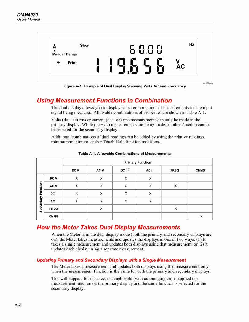
DMM4020 Users Manual
A-2
eue25.eps
Figure A-1. Example of Dual Display Showing Volts AC and Frequency
Using Measurement Functions in Combination The dual display allows you to display select combinations of measurements for the input signal being measured. Allowable combinations of properties are shown in Table A-1. Volts (dc + ac) rms or current (dc + ac) rms measurements can only be made in the primary display. While (dc + ac) measurements are being made, another function cannot be selected for the secondary display. Additional combinations of dual readings can be added by using the relative readings, minimum/maximum, and/or Touch Hold function modifiers.
Table A-1. Allowable Combinations of Measurements
Primary Function
DC V AC V DC I[1] AC I FREQ OHMS
DC V X X X X
AC V X X X X X
DC I X X X X
AC I X X X X
FREQ X X
Seco
ndar
y Fu
nctio
n
OHMS X
How the Meter Takes Dual Display Measurements When the Meter is in the dual display mode (both the primary and secondary displays are on), the Meter takes measurements and updates the displays in one of two ways: (1) It takes a single measurement and updates both displays using that measurement; or (2) it updates each display using a separate measurement.
Updating Primary and Secondary Displays with a Single Measurement The Meter takes a measurement and updates both displays using that measurement only when the measurement function is the same for both the primary and secondary displays. This will happen, for instance, if Touch Hold (with autoranging on) is applied to a measurement function on the primary display and the same function is selected for the secondary display.

Appendices Applications A
A-3
If the relative readings value of a dc voltage measurement is shown in the primary display and the dc voltage itself is shown in the secondary display, the Meter takes a single measurement and updates both displays with it.
Updating Primary and Secondary Displays with Separate Measurements If the measurement function in the primary display is different from that in the secondary display, the Meter updates each display using a separate measurement.
Taking Voltage and Current Measurements Using the Dual Display Most applications of the dual display listed in Table A-2 can be performed using a single set of test leads connected to the INPUT VZYR HI and LO terminals. However, to measure the voltage and current of an input signal requires three leads. Be sure that the voltage and current measurements share the same common as shown in Figure A-2. Then simply follow the precautions you would follow if you were making normal current measurements without a current clamp.
Table A-2. Sample Dual Display Applications
Primary Display
Secondary Display Applications
Volts DC Volts AC • Monitor dc level and ac ripple of power supply Troubleshoot amplifier circuits
Volts DC Current DC • Check power supply load regulation • Monitor UUT current draw and circuit voltages • Monitor loop current and voltage drop across transmitter
Volts DC Current AC • Line and load regulation tests • dc/ac or ac/dc converters
Volts AC Current DC • Line and load regulation tests • dc/ac or ac/dc converters
Volts AC Current AC • Line and load regulation tests • Transformer (magnetic circuit) saturation
Volts AC Frequency • Measure ac amplitude and frequency for line voltage and ac signal analysis
• Measure frequency response of an amplifier • Adjust ac motor control • Read noise in telecommunication applications • Adjust portable power generator to optimize power output • Set frequency compensation for a network
Current DC Current AC • Measure ripple and dc current draw of switching power supply • Measure current dissipation in protective fuse resistors used in
power supplies • Measure ripple and noise on a line
MN MX Actual Value • Show the minimum or maximum value recorded and the present measurement
REL Actual Value • Show actual measurement and the difference between this value and the relative base.

DMM4020 Users Manual
A-4
Table A-2. Sample Dual Display Applications (cont.)
Primary Display
Secondary Display
Applications
REL Resistance • Select and sort resistors. (See also "Using the Compare Function" in Chapter 3.)
HOLD Actual Value • Show actual measurement while holding a previous, stable measurement on the primary display
5-1/2 DIGIT MU LTIMETER
HI
LO
1000V 750V
2W/4W
MAX
INPUT SENSE
HI
LO
4W
10AmA
200 mAMAX 10A
MAX
1000 V CAT I 600 V CAT II
500 V pk
V
1V
300V
TEKTRONIX DMM4020
gdb27.eps
Figure A-2. DC Voltage and DC Current Measurement on Input Signal
The lead from the internal measuring circuitry of the meter to the LO terminal (on the front panel) is the same for both voltage and current measurements. The resistance of this lead is approximately .003 ohm. If current is being measured, therefore, a voltage drop will occur in the resistance that is common to both circuits. This internal resistance, when added to the external resistance of the lead from the COM input terminal will affect the accuracy of the voltage reading. For instance, if the external lead resistance is .007 ohm, the "total" common resistance is .010 ohm. If there is 1 A of current, the voltage reading would be affected by:
(1 A x.01 ohm ) = .01 V or 10 m V. Depending on the circumstances, this may be significant. If you want to measure dc voltage on an input signal in the primary display and dc current in the secondary display, proceed as follows: 1. Turn the Meter on. 2. Press D to select the dc voltage function for the primary display. 3. Press Q then E to select the dc current function for the secondary display. 4. Connect the leads to the test circuit as shown in Figure A-2 and read the
measurements on the display. Although current will be displayed as negative, it is in fact positive when interpreted according to current flow convention.
Appendices Applications A
A-5
Response Times Response time is the time between a change in an input and when that change is displayed. The meter’s response time depends on many factors: the measurement function selected, number of measurements being made (single measurement when only the primary display is used, or two measurements when both the primary and secondary display are used), the input level, range type (autorange or manual range), the measurement rate (slow, medium, or fast), and whether measurement types are mixed or not. (Measurements are either ac-type [ac volts or amps] or dc-type [all others]). Typical response times for a single measurement are shown in Table A-3. For a single measurement, results are displayed as soon as the correct range is found. However, additional time needs to be allowed for the measurement to be fully settled in order for the displayed result to meet the meter’s accuracy specifications. This "settling delay" varies, depending on the differences between the primary and secondary displays. The settling delay is longer when ac- and dc-type measurements are mixed. Examples of mixed ac and dc measurements are volts dc and amps ac, and volts ac and amps dc. Settling times are listed in Table A-4.
Update Rate in the Dual Display Mode The update rate is the time between successive measurements for a steady state signal. In the dual display mode (when both the primary and secondary displays are on), if the measurement functions or the ranges selected for the primary and secondary displays are different, the update rate for each measurement function will vary from the update rate for that measurement function when only the primary display is on. When the secondary display is on, the meter always waits for the measurement to be fully settled after changing the range or function before displaying a reading. The amount of delay depends on the functions and ranges selected for the primary and secondary displays as shown in Table A-4. Table A-5 lists the interval between measurements when the measurement function or range of the primary and secondary display differ. These intervals vary by measurement function, range, measurement rate (slow, medium, or fast), and measurement type (ac-and dc-type measurements mixed or not mixed).
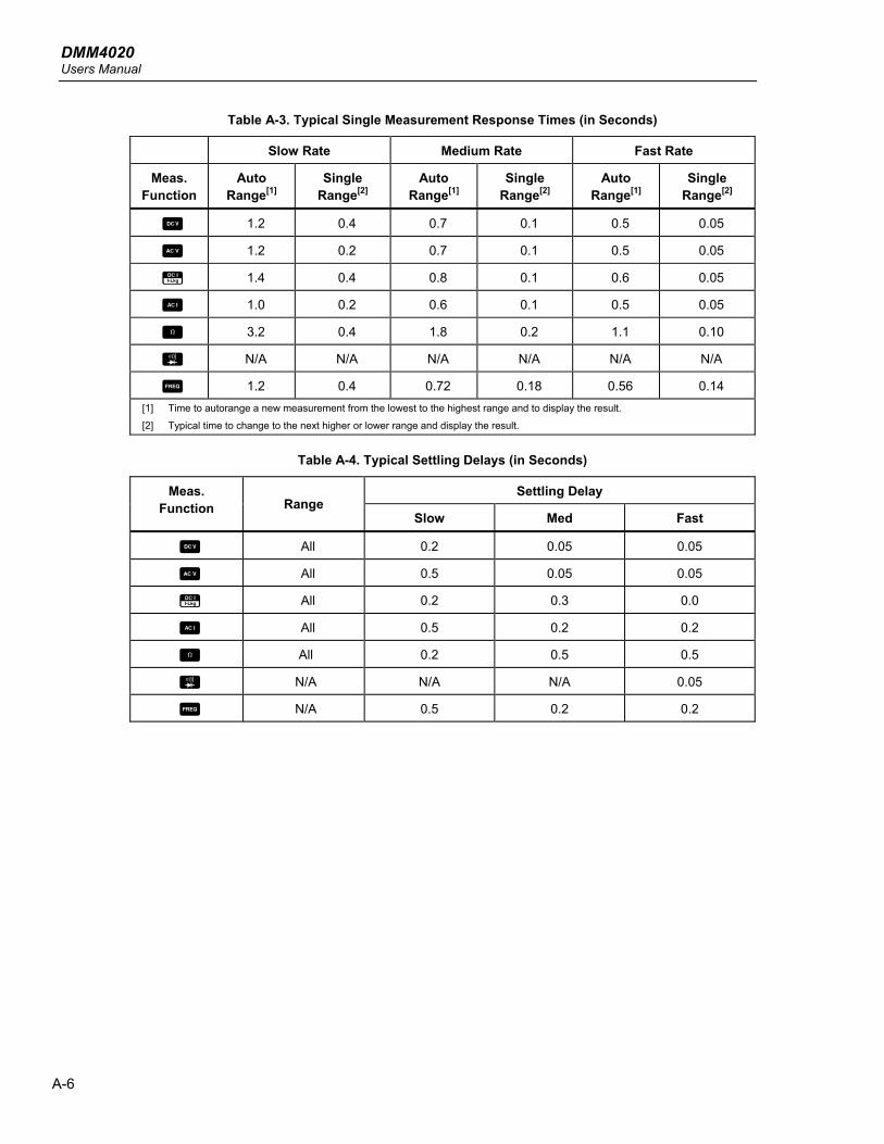
DMM4020 Users Manual
A-6
Table A-3. Typical Single Measurement Response Times (in Seconds)
Slow Rate Medium Rate Fast Rate
Meas. Function
Auto Range[1]
Single Range[2]
Auto Range[1]
Single Range[2]
Auto Range[1]
Single Range[2]
D 1.2 0.4 0.7 0.1 0.5 0.05
A 1.2 0.2 0.7 0.1 0.5 0.05
E 1.4 0.4 0.8 0.1 0.6 0.05
B 1.0 0.2 0.6 0.1 0.5 0.05
O 3.2 0.4 1.8 0.2 1.1 0.10
G N/A N/A N/A N/A N/A N/A
F 1.2 0.4 0.72 0.18 0.56 0.14 [1] Time to autorange a new measurement from the lowest to the highest range and to display the result.
[2] Typical time to change to the next higher or lower range and display the result.
Table A-4. Typical Settling Delays (in Seconds)
Settling Delay Meas. Function Range
Slow Med Fast
D All 0.2 0.05 0.05
A All 0.5 0.05 0.05
E All 0.2 0.3 0.0
B All 0.5 0.2 0.2
O All 0.2 0.5 0.5
G N/A N/A N/A 0.05
F N/A 0.5 0.2 0.2

Appendices Applications A
A-7
Table A-5. Typical Measurement Intervals (in Seconds) for Dual Display Measurements
Meas. Function Range Slow Med Fast
D All 1.2 1.0 0.9
A All 1.0 0.85 0.8
E All 1.2 1.0 0.9
B All 1.0 0.85 0.8
O N/A N/A N/A N/A
G N/A N/A N/A N/A
F N/A N/A N/A N/A
External Trigger The external trigger can be used with or without settling delays, as shown in Table A-4. (Refer to Table 4-3 for trigger types.) The amount of trigger delay varies depending on differences between the primary and secondary displays, as described in the previous section. When external trigger is enabled, the meter determines the ranges for the primary and secondary (if enabled) displays based on the input at that time. The meter is then ready to begin measuring the input on the optimum range as soon as the trigger is received. If the input changes so that either display autoranges after the trigger is received, the autoranging response times (as shown in Table A-3) may be required before each measurement result is displayed. The rear panel trigger input is edge sensitive. A low to high pulse (above +3 V) will be recognized as a trigger less than 3 ms.
Thermal Voltages Thermal voltages are the thermovoltaic potentials generated at the junction between dissimilar metals. Thermal voltages typically occur at binding posts and can be greater than 1 μV. When making low-level dc measurements, thermal voltages can present an additional source of error. Thermal voltages can also cause problems in the low ohms ranges. Some low-value resistors are constructed with dissimilar metals. Just handling such resistors can cause thermal voltages large enough to introduce measurement errors. Use the following techniques to reduce the effect of thermal voltages: 1. Use similar metals for connections wherever possible (e.g., copper-to-copper, gold-
to-gold, etc.). 2. Use tight connections. 3. Use clean connection (especially free of grease and dirt). 4. Use caution when handling the circuit under test. 5. Wait for the circuit to reach thermal equilibrium. (Thermal voltages are generated
only where there is a temperature gradient.)

DMM4020 Users Manual
A-8
Making Low-Level Current Measurements There are many applications where obtaining the utmost accuracy in low-level current measurements is critical. For example, determining the leakage current of a battery operated device in its standby mode is critical in determining the time before battery re-charge is needed. Traditional multimeters make these measurements using a shunt method shown in Figure A-3. The shunt resistor converts the current to be measured to a voltage, which is called the burden voltage. Since the internal impedance of the current source is in parallel with the shunt resistor, the current flowing in the shunt resistor is less than the actual value, thus causing an error.
A
VOUT
IIN
RSHUNTRInternal
eue28.eps
Figure A-3. Shunt Method of Low-Level Current Measurement
Another method of low-current measurement is the feedback resistor method shown in Figure A-4. The feedback resistor converts the current to be measured into a voltage. The high gain operational amplifier forces the burden voltage to approximately zero and thus reduces the error associated with the simple shunt measurement approach. The zero burden voltage measurement method used in the Meter gives a more accurate measurement of low-level (leakage) currents.
VOUT
IINRFeedback
RInternal
A
eue29.eps
Figure A-4. Zero Burden Voltage Low-Level Current Measurement

B-1
Appendix B 2X4 Test Leads
Introduction The optional Tektronix TL705 test leads simplify making 4-wire ohm measurements by integrating the Hi-Hi Sense and Lo-Lo Sense test leads into one cable. The Meter’s Input HI and LO jacks consist of two contacts. One contact is connected to HI or LO input circuits and the other contact is connected to the Sense input circuits. Like the input jacks, the 2x4 test lead also has two contacts that align with the input jack contacts to provide a four wire connection.
Ground tab
caw061.eps
Figure B-1. 2X4 Wire Test Leads
XW Warning To avoid electric shock and possible damage to the Meter, use the 2X4 Wire test leads as specified in this manual. Inspect the test leads before use. Do not use them if insulation is damaged or metal is exposed. Check the test leads for continuity. Replace damaged test leads before using the Meter.

DMM4020 Users Manual
B-2
1
Index
—A— Accessories, 1-13
—B— Bail
Adjustment of, 2-8 Removal of, 2-8
—C— Calibration, 3-24 Cleaning the Meter, 2-9 Compliance Information, 1-7
—D— Diode Test, 3-13 Display, 3-5
—E— Environmental Considerations
Equipment Recycling, 1-9 Restriction of Hazardous Substances, 1-9
—F— Fluke 45 Emulation Mode, 2-10 Front Panel Features, 3-3 Function Keys, 3-23 Fuses
Current-Input, 2-5 Line-Power, 2-4
—I— Impedances
Reference, 3-18 Installation in Equipment Rack, 2-9
—L— Line Voltage Selection, 2-4 List and Number Editors, 3-21
—M— Manuals, 1-11 Measurement
Current, 3-12 Frequency, 3-9 Resistance, 3-9
2-Wire, 3-10 4-Wire, 3-11
Voltage, 3-8
—P— Power Cord Types, 2-7 Power On, 2-7 Power-Up Configuration, 3-24
—R— Rear Panel Features, 3-7 RS-232 Pin Out, 3-16
—S— Safety
General safety summary, 1-3 Symbols and Terms, 1-5
Security Procedures, 1-12 Shift Button
Second Level Operations, 3-20 Specifications
Electrical, 1-15 Environmental, 1-14 General, 1-13
Storing Meter, 2-3

DMM4020 Users Manual
2
—T— Trigger Mode, 3-15
—U— Unpacking Meter, 2-3
User Documentation, 1-11
—W— Warranty, 1-14